MODEL 6629 BATTERY CHARGER - Global Product Support · 1.0 GENERAL INFORMATION 1.1 Introduction The...
52
IUNION SWITCH & SIGNALl(m] SERVICE MANUAL 7021 A member of the ANSALOO Group 5800 Corporate Drive, Pittsburgh, PA 15237 Delivery/Acceptance, Operation and Field Maintenance MODEL 6629 BATTERY CHARGER November, 1990 A-2/93-2993-1 Formerly Dynamic Sciences Limited Document Reference 176-0004-00 COPYRIGHT 1993, UNION SWITCH & SIGNAL INC. PRINTED IN USA ANSALDO Trasporti
Transcript of MODEL 6629 BATTERY CHARGER - Global Product Support · 1.0 GENERAL INFORMATION 1.1 Introduction The...

IUNION SWITCH & SIGNALl(m] SERVICE MANUAL 7021 A member of the ANSALOO Group 5800 Corporate Drive, Pittsburgh, PA 15237
Delivery/Acceptance, Operation and Field Maintenance
MODEL 6629 BATTERY CHARGER
November, 1990 A-2/93-2993-1
Formerly Dynamic Sciences Limited Document Reference 176-0004-00
COPYRIGHT 1993, UNION SWITCH & SIGNAL INC. PRINTED IN USA
ANSALDO Trasporti


NOTICE
Effective July, 1992, this document became the property of Union Switch & Signal Inc. All references to "Dynamic Sciences Limited" and "DSL" apply to Union Switch & Signal Inc.
For service on this Union Switch & Signal product, please contact:
Union Switch & Signal Inc. The Service Shop 645 Russell St. Batesburg, SC 29006
Toll-Free Phone: 1-800-652-7276 Fax: 803-532-2940

This page left blank intentionally.
Copyright 1990 DSL Dynamic Sciences Limited Confidential Proprietary Information
176-0004-00 Issue 1 2 of 52 90-November-12

PROPRIETARY CONFIDENTIAL INFORMATION
This document contains commercial and technical data and designs which are the exclusive property of DSL Dynamic Sciences Limited (DSL) and may contain proprietary information of others, which shall not be used, copied or disclosed in any way to any third party without the prior written consent of the Manager of Contracts of DSL. The recipient of this document, by its retention and use, agrees to maintain it in confidence using the same safeguards as it uses to protect its own confidential information.
PATENT INFORMATION
Patents are issued on the equipment described in this manual.
In the USA, the following patent is issued:
Rechargeable Battery, Patent 4, 554, 22.1
In Canada, the following patent is issued:
Rechargeable Battery, Patent 1,230,653
REGISTERED TRADEMARK
DIGITAIR is a registered trademark of DSL Dynamic Sciences Limited (United States Trademark Registration No. 1,293,996; Canadian Trademark Registration No. 296,425). DIGITAIR is also a registered trademark of DSL in Australia, Germany, France, Great Britain, and Italy.
Copyright 1990 DSL Dynamic Sciences Limited Confidential Proprietary Information
176-0004-00 Issue 1 3 of 52 90-November-12

PREFACE
INTENT OF MANUAL:
The intent of Service should understood.
this be
document is to assist in repair and service. attempted only if the manual is clearly
FURTHER SUPPORT:
Questions regarding the manual should be directed to:
Marketing Services Department DSL DYNAMIC SCIENCES LIMITED 359 Ste Croix Blvd. st. Laurent, Quebec Canada H4N 2L3
Telephone: Fax: Telex:
(514) 744-5571 (514) 744-0053 05-825803
Servicing is available from DSL Headquarters at the address given above and from the following DSL Service Offices:
DSL Vancouver 2820 Production Way Burnaby, B.C. Canada V5A 4T6
Telephone: From u.s: Fax: Telex:
DSL Hershey
(604) 444-4122 (800) 663-8667 (604) 444-4923 04-352848 Ver
1421 Fishburn Road Hershey, PA U.S.A. 17033
Telephone: From u.s: Fax:
(717) 533-4618 (800) 544-8879 (717) 533-4468
Copyright 1990 DSL Dynamic Sciences Limited Confidential Proprietary Information
176-0004-00 Issue 1 4 of 52 90-November-12

WARRANTY
(a) Seller's liability in respect of any defect in or failure of the Products supplied hereunder, or for any loss, damage or injury attributable thereto, is limited to making good by repair or replacement, at Seller's discretion, defects which under proper use, care and maintenance, appear therein and arise solely from defective design, materials or workmanship, within a period of twelve (12) months from delivery, PROVIDED ALWAYS THAT:
(i) Buyer advises Seller of any such defect or failure within thirty (30) days of its occurrence; and
(ii) Buyer obtains Seller's authorization to return, at Buyer's expense, the defective Product or part, in the following way; upon receipt by Seller of the serial number and proper identification of the defective Product, Seller shall issue to Buye~ a return.authorization number which must appear on labels and documents accompanying the returned Product. A full description of the fault must also accompany each return.
(b) Seller shall return the repaired unit or a replacement thereof prepaid to Buyer.
(c) Repair, attempted repair or alteration, by other than Seller or its authorized representative, without prior authorization in writing by Seller, or alteration or effacement of any part of Seller's nameplate or marking affixed to a Product supplied by Seller, shall void this Warranty.
(d) Products not identified by Seller's nameplate are expressly excluded from this Warranty. However, Seller will pass on to Buyer the warranties, received from its suppliers, if any and to the extent it is permitted to do so, but only so far as to not impose on Seller a liability greater than that imposed on Seller by this Warranty.
(e) No warranty is given in respect of any consumable items.
(f) NO WARRANTIES, WHETHER STATUTORY, EXPRESSED OR IMPLIED, INCLUDING BUT NOT LIMITED TO THOSE OF MERCHANTABILITY OR FITNESS FOR ANY PARTICULAR PURPOSE, OTHER THAN THOSE EXPRESSED IN THIS ARTICLE SHALL APPLY TO THE PRODUCT OR SERVICE AND, IN ANY EVENT, SELLER SHALL NOT BE LIABLE TO BUYER OR ANY OTHER PERSON FOR ANY DAMAGE, INJURY OR LOSS, INCLUDING WITHOUT BEING LIMITATIVE, LOSS OF USE, REVENUE OR PROFIT, OR ANY OTHER ECONOMIC LOSSES, OR FOR ANY DIRECT OR INDIRECT, INCIDENTAL OR CONSEQUENTIAL DAMAGES.
Copyright 1990 DSL Dynamic Sciences Limited Confidential Proprietary Information
176-0004-00 Issue 1 5 of 52 90-November-12

CAUTION
o The Model 6629 Charger is intended for DSL DIGITAIR batteries only. Attempts to charge other batteries may cause damage to the batteries or to the Charger.
o Recharge batteries only when the temperature of the batteries is between l0°C a~~ 30°C (50°F and 86°F). Temperatures outside this range may affect battery performance. Always allow a hot battery to cool down before recharging. CHARGING BATTERIES THAT ARE TOO HOT OR TOO COLD MAY BE HAZARDOUS.
o Do not cover or restrict air circulation around the Charger.
o To ensure good electrical connections, clean the battery contacts before servicing.
o Only qualified technicians who thoroughly understand this manual should open the Charger or attempt to service it. Always disconnect power before opening Charger case.
Copyright 1990 DSL Dynamic Sciences Limited Confidential Proprietary Information
176-0004-00 Issue 1 6 of 52 90-November-12

1. 1.1 1.2 1.3 1.4 1.5 1.6
2. 2.1 2.2 2.3
3. 3.1 3.2 3.3 3.4 3.5
4. 4.1 4.2 4.3 4.4 4.5 4.6 4.7 4.8 4.9
5. 5.1 5.2 5.3 5.4 5.5 5.6
6. 6.1 6.2 6.3 6.4 6.5
7.
8.
TABLE OF CONTENTS
GENERAL INFORMATION Introduction Functional Description Charge Time Termination of Fast Charge Temperature sensors Specifications
DELIVERY/ACCEPTANCE PROCEDURE Receiving Procedure General Test Operational Test
OPERATING INSTRUCTIONS Introduction Starting the Unit Charging Battery Temperature Sensing Summary of Lamp and Sound Indicators
FAILED BATTERY INDICATIONS Introduction Shorted Battery FAIL 1 (Partial Short) FAIL 2 (Low Battery Voltage) FAIL 3 (Depressed Battery Voltage) Dry Cell Faulty Battery Connection Open Battery Venting Battery
THEORY OF OPERATION General Auxiliary Circuit Control Circuit Charging Drivers Display Indicators Interface Jack
AUDIO/VISUAL INDICATORS Good Battery Indications Faulty Battery Indications Temperature-Related Indications System Indications Failures of the Charger
PARTS LIST
DRAWINGS
Copyright 1990 DSL Dynamic Sciences Limited Confidential Proprietary Information
Page
9 9 9
11 11 13 13
15 15 15 15
17 17 17 17 18 18
21 21 21 21 21 22 22 22 22 22
25 25 25 26 27 29 29
31 31 32 33 34 35
41
47
176-0004-00 Issue 1 7 of 52 90-November-12

This page left blank intentionally.
Copyright 1990 DSL Dynamic Sciences Limited Confidential Proprietary Information
176-0004-00 Issue 1 8 of 52 90-November-12
1.0 GENERAL INFORMATION
1.1 Introduction
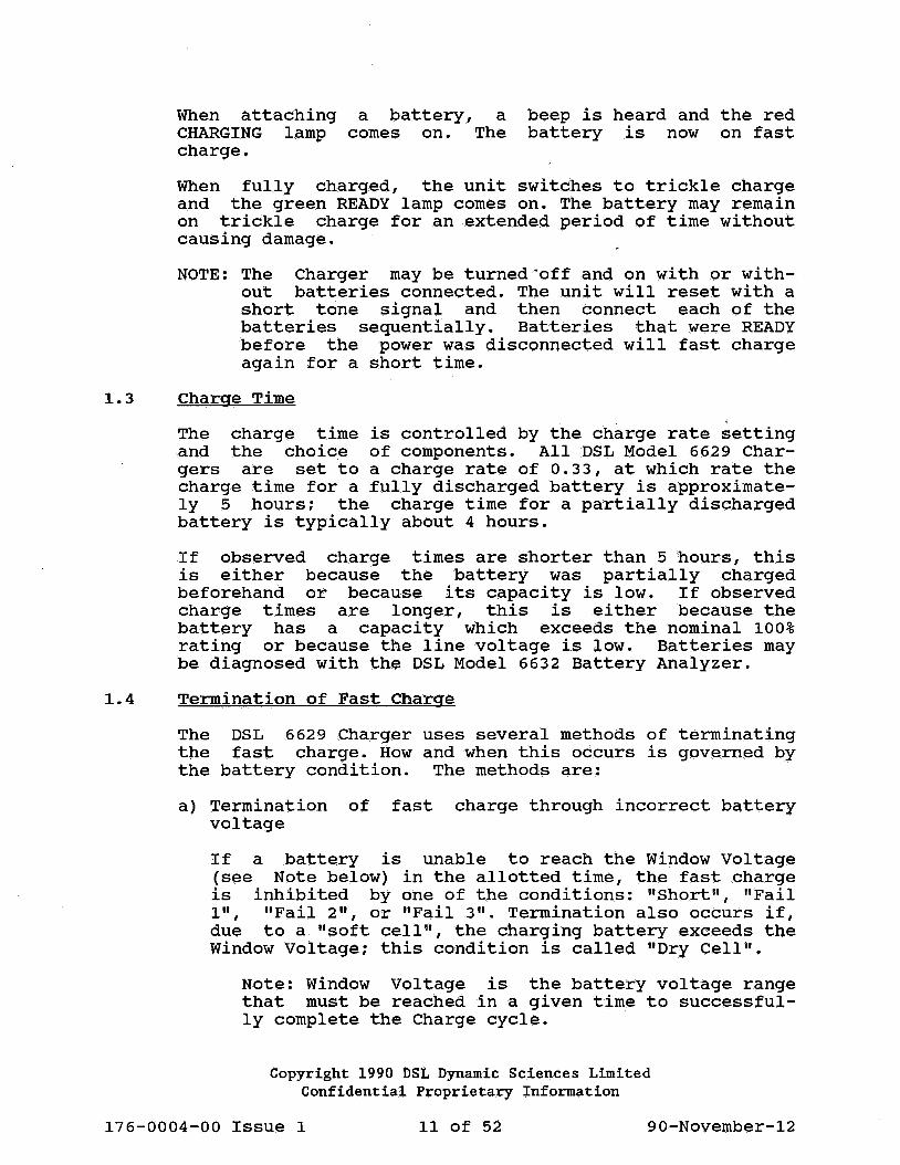
The DSL Model 6629 Charger, illustrated in Figure 1, is a fully automatic advanced microprocessor-controlled fast charger for DIGITAIR nickel-cadmium batteries. Each unit can accommodate up to 4 batteries at once.
To improve charging efficiency, the DSL 6629 Charger uses the Reverse Load charge method. Reverse Load is a pulse charge method that intersperses discharge current cycles throughout the charging process. Increased charge efficiency, cooler batteries, and reduced "memory" phenomenon are the result of this new method.
The DSL 6629 Charger assists the user with audible and visible signals to indicate the battery status. Faulty batteries are diagnosed and the cparge.cycle is terminated in time to protect the batteries and the Charger.
Nickel-cadmium batteries which have been stored in the uncharged state for an extended period of time may exhibit less than their rated capacity. This condition cannot be rectified by a single charge on the Model 6629 Charger although it will be improved over time.
It is recommended that DIGITAIR batteries that are new, or which have been stored unused for twelve (12) months or longer, be exercised by discharging to approximately 10 Volts (i.e. 1 Volt per cell) and then recharging, two or three times, in order to develop their full capacity. This can be done by discharging the batteries in the DIGITAIR Highly Visible Marker (HVM) light and then recharging on the Model 6629 Charger, or by using the DSL Model 6632 Battery Analyzer.
The DSL 6629 Charger is equipped with four "stations". Each station accepts one battery and works independently of the others. Charging defective batteries will not harm the unit. Overloading of the system is virtually impossible.
1.2 Functional Description
To install the Charger, connect the power cord to line voltage and turn the power on. A short tone signal is heard and all lamps come on momentarily. With no battery in place, all CHARGING and READY lamps will then remain off.
Copyright 1990 DSL Dynamic Sciences Limited Confidential Proprietary Information
176-0004-00 Issue 1 9 of 52 90-November-12

Figure 1 Model 6629 Battery Charger
Copyright 1990 DSL Dynamic Sciences Limited Confidential Proprietary Information
176-0004-00 Issue 1 10 of 52 90-November-12
When attaching CHARGING lamp charge.
a battery, a comes on. The
beep is heard and the red battery is now on fast
When fully charged, the unit switches to trickle charge and the green READY lamp comes on. The battery may remain on trickle charge for an extended period of time without causing damage.
NOTE: The Charger may be turned·off and on with or without batteries connected. The unit will reset with a short tone signal and then connect each of the batteries sequentially. Batteries that were READY before the power was disconnected will fast charge again for a short time.
1.3 Charge Time . .
The charge time is controlled by the charge rate setting and the choice of components. All DSL Model 6629 Chargers are set to a charge rate of 0.33, at which rate the charge time for a fully discharged battery is approximately 5 hours; the charge time for a partially discharged battery is typically about 4 hours.
If observed charge times are shorter than 5 hours, this is either because the battery was partially charged beforehand or because its capacity is low. If observed charge times are longer, this is either because the battery has a capacity which exceeds the nominal 100% rating or because the line voltage is low. Batteries may be diagnosed with the DSL Model 6632 Battery Analyzer.
1.4 Termination of Fast Charge
The DSL 6629 Charger uses several methods of terminating the fast charge. How and when this occurs is governed by the battery condition. The methods are:
a) Termination of fast charge through incorrect battery voltage
If a battery is unable to reach the Window Voltage (see Note below) in the allotted time, the fast charge is inhibited by one of the conditions: "Short", "Fail 1 11 , "Fail 2 11 , or "Fail 3 11 • Termination also occurs if, due to a "soft cell", the charging battery exceeds the Window Voltage; this condition is called "Dry Cell".
Note: Window Voltage is the battery voltage range that must be reached in a given time to successfully complete the Charge cycle.
Copyright 1990 DSL Dynamic Sciences Limited Confidential Proprietary Information
176-0004-00 Issue 1 11 of 52 90-November-12

b) Full charge detection through Negative Slope
Most batteries respond to the Negative Slope Detector for termination. In the carefully selected Window Voltage, the computer monitors the-voltage pattern of the charging battery. Upon approaching full charge, the battery voltage rises sharply, peaks, and starts to fall off. This decrease in voltage (i.e., the Negative Slope) is detected, a triple beep is heard and the green READY lamp comes on.
c) Fast charge inhibit through Peak Timeout Timer
on certain batteries, no sufficient decrease in voltage is detected upon full charge. When this occurs, the Peak Timeout Timer will terminate the fast charge instead.
Typical reasons for failing to produce the n~gative slope are:
- Battery has poorly matched cells; leaky cell(s); - Battery has
- Battery is new and is being charged for the first time; or
- Battery had time.
been in discharged condition for a long
Similar to the Negative Timeout Timer produces a READY lamp comes on.
Slope Detector, the Peak triple beep and the green
NOTE: The careful observer may notice different pitches of the triple beep tones. If the fullcharge detection occurs through the Negative Slope Detector, a high pitched triple beep is heard (2400 Hz); if it is caused by the Peak Timeout Timer, a low pitched triple beep occurs (674 Hz).
d) Fast charge disabled through "Dry Cell" condition
A battery normally fails due to low capacity before it dries out. However, if a Dry Cell condition exists, the Charger will disable the fast charge. The Dry Cell condition may show up after only a few minutes or after hours of charging.
Copyright 1990 DSL Dynamic Sciences Limited Confidential Proprietary Information
176-0004-00 Issue 1 12 of 52 90-November-12

1.5 Temperature Sensors
Temperature sensors are installed at each battery station. Should the battery case temperature exceed 44°C (111°F), the sensor terminates al'l charge current. A hot battery is indicated by rapid flashing of the red CHARGING lamp. After the battery has cooled down to 40°C (104°F), trickle charge commences. The CHARGING lamp alternates with the READY lamp. To reset, remove and replace the battery. ·
If the temperature is less than 15°C (59°F), trickle charge is applied and the CHARGING lamp flashes once per second. After the temperature rises above 15°C (59°F), the battery is fast charged and the cycle proceeds as usual.
It should be noted that there is no beep signal when inserting a battery that is out of temperature range.
1.6 Specifications
Power source:
Current:
Primary fuse:
Control circuit fuse:
115 VAC +/- 15%, 60 Hz (unless otherwise stated on the label on the Charger itself)
1.4A
2A circuit breaker
1.6A, 5x20mm, time lag
Maximum charge current: SA
Dimensions:
Weight:
Number of stations:
Charge method:
Full charge detection:
Indicators.:
36cm wide, 22cm high, 24cm deep (14.25" wide, 8.5" high, 9.5" deep)
6.6 kg (14.6 lb)
4
Reverse Load. Fast charges battery; then switches to trickle charge when fully charged.
Negative Timer as trolled).
Slope with Peak Timeout override (Software con-
Visible (lamps). actually LEDs Diodes). Audible (sounder).
These lamps are (Light Emitting
Copyright 1990 DSL Dynamic Sciences Limited Confidential Proprietary Information
176-0004-00 Issue 1 13 of 52 90-November-12

Meanings of Indicators:
CHARGING lamps (red LEDs)
READY lamps (green LEDs)
POWER ON lamp (amber LED)
Single beep tone:
Triple beep tone:
Wailing sound:
Continuous sound:
Beeping sound:
On steady: Battery on fast charge Flashing: but of temperature
range
On steady: Battery ready, trickle · charge
Flashing: Battery voltage incorrect
On steady: Power on
Battery contact established
Battery charge
switches
Reverse polarity
Battery shorted
Dry Cell condition
to trickle
Charge & Discharge Currents (per station):
Fast Charge Rate: Fast Charge Current:
Trickle Charge Current: Discharge Current:
Charge Time:
Reset:
0.33 A/Ah 1.33 A Nominal, unregulated (i.e., Fast Charge Rate x Nominal Battery Capacity) 235 mA Nominal, unregulated
1. 33 A Regulated
5 hours nominal (for a typical discharged battery).
By removing of battery.
Temperature protection: Fast charge tween 15°C lll°F)
is and
enabled only be-440C (59°F and
Copyright 1990 DSL Dynamic Sciences Limited Confidential Proprietary Information
176-0004-00 Issue 1 14 of 52 90-November-12

2.0 DELIVERY/ACCEPTANCE PROCEDURE
2.1 Receiving Procedure
The box should contain the Charger with its integral power cable and the User Guide.
Before opening the box, check for, and record, any damage to the outside of the box. Remove Charger from the box; check for, and record, any damages.
If the unit is damaged, the shipper should be notified immediately. All packing material and contents must be kept available for inspection by the shipper's claim agent. Failure to do this may result in denial of liability for damage by the shipper.
2.2 General Test
Follow the power up procedure given in Section 3.2 below.
2.3 Operationa1 Test
Charge a battery as described in Section 3.3 below.
Copyright 1990 DSL Dynamic Sciences Limited Confidential Proprietary Information
176-0004-00 Issue 1 15 of 52 90-November-12

This page left blank intentionally.
Copyright 1990 DSL Dynamic Sciences Limited Confidential Proprietary Information
176-0004-00 Issue 1 16 of 52 90-November-12

3.0 OPERATING INSTRUCTIONS
3.1 Introduction
The Charger has four battery positions or "stations". Each position has locating pins to ensure correct placement of the battery and to prevent reverse polarity connection. Each battery station functions independently. Charging of a battery is automatic and starts when the battery is placed on the Charger. Full charge is detected automatically, after which the battery receives a trickle charge to keep it at full capacity. Audible and visible signals indicate battery status. Faulty batteries are diagnosed and charging stopped in time to protect the battery and the Charger.
3.2 starting the Unit
Connect the Charger to an appropriate power ~upply, normally 115V AC. See label on back of Charger.
on power up, momentarily. green lamps remains on.
3.3 Charging
a single tone is heard and all lamps come on With no batteries in place, the red and remain off and the yellow POWER ON lamp
When a battery is placed in charging position, a beep tone is heard indicating proper contact. The red CHARGING lamp comes on showing that the battery is on fast charge.
Typical charge time for a battery in good condition is approximately 5 hours. This will be less if the battery capacity is low or if the battery was partially charged initially. If the charge time is longer than 5 hours, either the line voltage is low or the battery capacity exceeds the nominal rating.
When a battery is fully charged, a triple beep tone is heard, the green READY lamp comes on, the red CHARGING lamp goes off, and the Charger switches to trickle charge.
Batteries may be left on trickle charge for extended periods without harming the batteries.
NOTE: The Charger may be turned off and on with or without batteries connected. The Charger will reset with the power on tone and then connect each battery sequentially. Batteries that were READY before the power was disconnected will charge again for a short period of time.
Copyright 1990 DSL Dynamic Sciences Limited Confidential Proprietary Information
176-0004-00 Issue 1 17 of 52 90-November-12

3.4 Battery Temperature Sensing
The DSL 6629 Charger is equipped with a temperature sensor at each battery station •
. Should the battery case temperature exceed 44°C (lll°F), the red CHARGING lamp will flash. After the battery has cooled down, trickle charge will commence indicated by alternate flashing of the red and green lamps. To reset, remove battery. ·
If the temperature sensor measures less than 15°C (59°F), only trickle charge is applied, indicated by a slow flashing of the red CHARGING lamp. When the temperature rises to 15°C (59°F), the normal fast charge cycle will commence.
NOTE:
(a) There is no beep tone when a battery temperature range is placed on the Charger.
' out of
sensor at each station measures the the battery case; for cold batteries
accurately reflect the internal The following warm-up times are
when batteries have been exposed to low for several hours.
(b) The temperature temperature of this may not temperature. recommended temperatures
Temperature: 0°C (32°F) -20°C (-4°F) -40°C (-40°F) Warm-up time (at room temperature): 4 hours 8 hours 12 hours
*** DO NOT CHARGE COLD BATTERIES ***
3.5 Summary of Lamp and Sound Indicators
Table 3-1 provides a summary of the lamp and sound indicators.
Copyright 1990 DSL Dynamic Sciences Limited Confidential Proprietary Information
176-0004-00 Issue 1 18 of 52 90-November-12

LAMP
Yellow(POWER ON)
Red (CHARGING)
Green (READY)
Green (1 flash/sec)
Green (1 flash/sec)
Green (2 flashes/sec)
Green (4 flashes/sec)
Green (4 flashes/sec)
Red (random flash)
Red (1 flash/sec)
Red (4 flashes/sec)
Red & Green (4 flashes/sec)
Red or Green
SOUND
None
Single Beep
Triple Beep
Continuous
None
None
None
Continuous
Random
None
None
None
Any
INDICATES
Power On
Battery on Fast Charge
Battery Fully Charged -Ready for Use
Fault - "SHORT"
Fault - "FAIL l"
Fault - "FAIL 2"
Fault - "FAIL 3"
Fault - "DRY CELL"
Faulty Battery Connection
Cold Battery
Hot Battery
Hot Battery has Cooled -Remove & Replace to Reset
If no battery in place -System Fault
TABLE 3-1
SUMMARY OF INDICATORS
Copyright 1990 DSL Dynamic Sciences Limited Confidential Proprietary Information
176-0004-00 Issue 1 19 of 52 90-November-12

This page left blank intentionally.
Copyright 1990 DSL Dynamic Sciences Limited Confidential Proprietary Information
176-0004-00 Issue 1 20 of 52 90-November-12
4.0 FAILED BATTERY INDICATIONS
4.1 Introduction
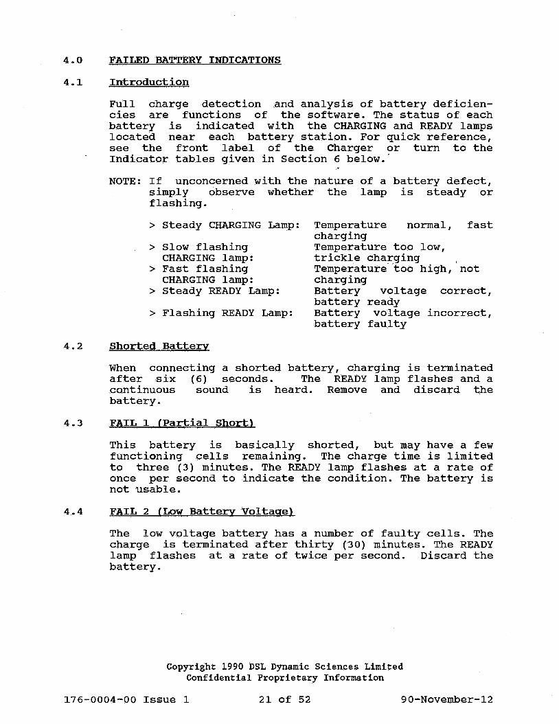
Full charge detection and analysis of battery deficiencies are functions of the software. The status of each battery is indicated with the CHARGING and READY lamps located near each battery station. For quick reference, see the front label of the Charger or turn to the Indicator tables given in Section 6 below.·
NOTE: If unconcerned with the nature of a battery defect, simply observe whether the lamp is steady or flashing.
> Steady CHARGING Lamp:
> Slow flashing CHARGING lamp:
> Fast flashing CHARGING lamp:
> Steady READY Lamp:
> Flashing READY Lamp:
4.2 Shorted Battery
normal, Temperature charging Temperature too low, trickle charging ,
fast
Temperature· too high, not charging Battery battery Battery battery
voltage ready voltage
faulty
correct,
incorrect,
When connecting a shorted battery, charging is terminated after six (6) seconds. The READY lamp flashes and a continuous sound is heard. Remove and discard the battery.
4.3 FAIL 1 (Partial Short)
This battery is basically shorted, but may have a few functioning cells remaining. The charge time is limited to three (3) minutes. The READY lamp flashes at a rate of once per second to indicate the condition. The battery is not usable.
4.4 FAIL 2 (Low Battery Voltage)
The low voltage battery has a number of faulty cells. The charge is terminated after thirty (30) minutes. The READY lamp flashes at a rate of twice per second. Discard the battery.
Copyright 1990 DSL Dynamic Sciences Limited Confidential Proprietary Information
176-0004-00 Issue 1 21 of 52 90-November-12

4.5 FAIL 3 {Depressed Battery Voltage)
Due to one or more faulty cells, the battery is unable to reach the Window Voltage. The charge is terminated after three (3) hours. The READY lamp· flashes four (4) times per second to inform the user of this deficiency.
Note: Unlike "Short", occurrence of "Fail 3" completely but switches may have limited use, but
4.6 Dry Cell
"Fail 1 11, and "Fail 2 11
, the does not terminate the charge to trickle charge. The battery
should ~e marked as faulty.
A "Dry Cell" condition occurs when one or more cells lack electrolyte. This condition makes the battery "soft" in which state it can no longer clamp the terminal voltage down when charging. A four-flash-per-second READY lamp and continuous tone indicate this condition. Charging is terminated. The battery can no longer be used and should be discarded.
If a cold battery is fast charged, an apparent "Dry Cell 11
condition may also occur. Allow the battery to warm up for several hours before charging.
4.7 Faulty Battery Connection
A faulty battery connection raises the terminal voltage when in Charge mode. This condition switches the Charger between Reset (no battery) and Charge (battery inserted). Random flashing of the CHARGING lamp occurs and beep tones are heard.
To correct this problem, clean all connections on both the Charger and the battery. If no improvement is apparent, the battery is probably faulty and should be discarded.
4.8 Open Battery
The battery cannot accept a charge current, and the Charger remains on Reset. No lamps or tone signals are activated. Check and clean all contacts.
4.9 Venting Battery
Older batteries often develop a problem whereby, due to aging, the cells become increasingly mismatched. This is aggravated by the fact that the weak cells reach full charge before the good ones do, thus causing elevated temperature and excessive pressure in these cells. A further deterioration of the weak cells is therefore inevitable.
Copyright 1990 DSL Dynamic Sciences Limited Confidential Proprietary Information
176-0004-00 Issue 1 22 of 52 90-November-12

When a cell reaches excessive pressure, venting occurs. A popping or hissing sound may be heard. There is no danger to battery or equipment; however, repeated venting can lead to the "Dry-Cell" condition described above.
Copyright 1990 DSL Dynamic Sciences Limited Confidential Proprietary Information
176-0004-00 Issue 1 23 of 52 90-November-12

This page left blank intentionally.
Copyright 1990 DSL Dynamic Sciences Limited Confidential Proprietary Information
176-0004-00 Issue 1 24 of 52 90-November-12

5.0 THEORY OF OPERATION
5.1 General
The circuitry of the DSL 6629 Charger is divided into four sections: Auxiliary Circuit, Control Circuit, Charging Drivers, and Display Indicators (the LED indicator lamps). A block diagram and schematic of the complete Charger are provided in Section~ below.
5.2 Auxiliary Circuit
The Auxiliary circuit consists of: Power Supply, Overload Detector, Reset Circuit, Sounder driver, POWER ON lamp driver, Clock Oscillator, and Code Selector.
(a) Power Supply
The power supply consists of rectifiers CRl and CR2, and a three-terminal regulator Ul which has internal protection for both overcurrent and excessive temperature. output voltage is set to the required 5.12 voe using potentiometer Rl.
(b) overload Detector
The overload detector senses the transformer temperature via a thermistor and shuts the Charger down should the transformer exceed a certain temperature.
Since the charge rate on all DSL Model 6629 Chargers is fixed, the current demand on Tl is fixed. As such, the thermistor is not required and is therefore not installed on any DSL Model 6629 Charger. The following description is included for completeness only.
The detector circuit consists of capacitor and comparator U2B. If a thermistor (RTl) were installed, it would be connected to P2. On sensing high temperature, RTl would allow Cl to charge, switching comparator U2B output Low then High.
The rising positive edge applied to processor U3 (INT 1 input) would place the processor in "sleep mode", shutting down the Charger.
Copyright 1990 DSL Dynamic Sciences Limited Confidential Proprietary Information
176-0004-00 Issue 1 25 of 52 90-November-12

(c) Reset Circuit
The Reset circuit provides a Power On reset to the microprocessor when power is first applied. C4 charging at U2A pin 5, causes comparator U2A output pin 2 to switch Low for a few milliseconds and then to switch High. The Low applied to U3 pin 23 resets the microprocessor U3.
A Watchdog timer circuit consisting of U2C and U2D monitors microprocessor U3 for continuous activity and enables the Reset circuit should normal operations cease. Pulses superimposed on the POWER ON lamp output line (U3 pin 24) are monitored by pulse shaper U2D.
Should pulse activity second, the output of output, normally High, fed to comparator microprocessor Reset.
cease for more U2D will go High. now switches Low.
U2A via C7
then about one Comparator U2C This signal is initi&ting a
The Watchdog timer circuit also triggers a reset if the input AC power rises slowly. (e.g., after a brown-out).
(d) Code Selector
The Code Selector is unused in the DSL 6629 Charger. The charge rate was at one time set by jumpers placed on the Code Selector header, but now the rate is fixed at 0.33 in firmware. The Code Selector header should have no jumpers placed on it.
5.3 Control Circuit
Refer to both the block diagram and the schematic for the following descriptions; both drawings are provided in Section 8 below.
The following items processor U3, EPROM Addressable latch U6.
comprise the Control Circuit: Micro(or PROM) U4, latch U5, and 8-bit
EPROM U4 contains the program for the Charger's microprocessor. The microprocessor U3 uses a multiplexed address/data bus DB 0-7 to obtain its instructions from U4.
To read an instruction from the EPROM, the microprocessor first outputs 13 address bits. The lower order address bits 0-7 are latched in D latch U5. The higher order bits remain on. the direct address bus throughout the read cycle. The EPROM output is then enabled allowing the reading of data, by the microprocessor, on DB lines Oto 7.
Copyright 1990 DSL Dynamic Sciences Limited Confidential Proprietary Information
176-0004-00 Issue 1 26 of 52 90-November-12

Latch U6 acts as an addressable LED driver for all four stations.
The Control Circuit charging stations via U3 provides Control drivers as follows:
(a) Control Signals
provides control signals for the four the Charging 'Drivers. Microprocessor and Supervisory information to the
- three lines provide each Charging Driver with individual digital control signals for Fast Charge, Trickle Charge, and Reverse Load.
> Fast Charge: Active when high; low no charge > Trickle Charge: Active when high; low no charge > Reverse Load: Active when high; low no activity
(b) Supervisory Signals
- three lines from each Charging Driver provide analog, supervisory input signals to the microprocessor for Battery Voltage (V-sense), Battery Temperature (V-temp), and Reverse Polarity.
> v-sense:
> v-temp:
Analog, battery below).
O to 5.12V , indicates voltage (see Section 5.6
Analog, o to 5.12V, indicates battery temperature (see Sectin 5.6 below).
> Reverse Polarity: Normally high, low when battery reverse polarized.
5.4 Charging Drivers
The function of the Charging Drivers is to provide Fast Charge, Trickle Charge, and Reverse Load cycling.
The DSL 6629 Charger contains four Charging Drivers, one for each battery station. The charge current and hence charge time is determined by the choice of components and by the control signals from microprocessor U3.
As all drivers are identical, only one circuit will be described. Refer to the block diagram and the schematic for the following descriptions.
Copyright 1990 DSL Dynamic Sciences Limited Confidential Proprietary Information
176-0004-00 Issue 1 27 of 52 90-November-12

(a) Driver Component Designation
All components in the Charging Drivers are identified by a three-digit number. The first digit designates the Charging Driver (Driver 1, 2, 3 or 4). The second and third digits position the components, and are repeated on each Charging Driver as their allocations are the same for all positions. In the following description, the first digit is replaced by an "x", In this way, the description is of Charging'Driver "x", where "x" may be 1, 2, 3, or 4.
(b) Input/Output
Each Charging Driver responds to the three control signals described in Section 5.3(a) above and provides the supervisory signals described in 5.3(b).
(c) Fast Charge
Voltage is applied on the Fast Charge line, via Rx03 to pin 1 of UxOl. Pin 2 of UxOl is connected to the unregulated DC line from CR3; this has a high 60 cycle ripple content.
The output of UxOl at pin 1 applies a ground potential at a rate of 60 times per second, synchronous with the line voltage. Capacitor Cx02, also connected to pin 1 of UxOl, acts as an integrator to produce a sawtooth waveform.
This sawtooth wave is compared with the reference voltage on pin 5 of UxOl. The resulting output pulse on pin 2 of UxOl coincides with the positive half of the AC and turns on driver QxOl-1, allowing charge current to flow through the series pass transistor Qx02.
(d) Trickle Charge
Unlike fast charge, trickle charge uses only a fraction of the positive AC pulse. A different timing ratio of Rx04 and Cx02 produces a lower saw-tooth voltage. The pulse width, and hence the trickle charge current, are determined by the value of Rx04. (A higher resistance will produce less current). The trickle charge current is set to 235 mA nominal on the 6629 Charger; this value is approximate and varies both with battery terminal voltage and with line voltage.
Copyright 1990 DSL Dynamic Sciences Limited Confidential Proprietary Information
176-0004-00 Issue 1 28 of 52 90-November-12

(e) Reverse Load
A special feature of the DSL 6629 Charger is Reverse Load cycling by which a brief discharge is applied between each charge pulse. This feature stimulates the battery and reduces the "memory" phenomenon associated with nickel-cadmium batteries.
On both fast charge and trickle charge, Rx12 and Rx13 produce a reference voltage (pin 10 of UxOl) that compares with the AC ripple which is superimposed on DC (pin 11 of UxOl). The resulting output (pin 13) is a zero going pulse, turning Qx03 on during that period.
The Reverse Load is active between charge pulses. The average Reverse Load discharge is approximately 10% of the battery's Ampere-hour (Ah) rating.
(f) Reverse Polarity Detector
If a negative voltage potential is read on the voltage divider of Rxl8 and Rxl9, pin 14 of UxOl switches from High to Low, informing the microprocessor of a reverse polarity condition. CRx03 acts as buffer. If a battery is connected backwards, the charge current is immediately stopped.
(g) Temperature Sensor
The voltage reading produced on the divider consisting of Rx25 and the thermistor is fed to the A/D converter of the microprocessor. The thermistor (NTC) has a nominal resistance of lOOK ohms at 25°C (77°F).
If the thermistor becomes disconnected, the software will simply ignore the temperature sensing.
5.5 Display Indicators
The LEDs are driven the Control Circuit. refer to Tables 6-1 manual.
5.6 Interface Jack
by the 8-Bit Addressable Latch U6 of For definition of the LED signals, through 6-4 in Section 6 of this
The DSL 6629 Charger is equipped with an internal Interface Jack, P4, a 2x5 header on the main PCB. It provides access to the serial lines to the microprocessor and has the analog reference voltages (V-sense) of all four batteries.
Copyright 1990 DSL Dynamic Sciences Limited Confidential Proprietary Information
176-0004-00 Issue 1 29 of 52 90-November-12

NOTES: 0 Since no function is presently implemented for the serial lines, the Interface Jack P4 is useful only for monitoring the sensed battery voltages.
0 V-sense is the battery voltage dropped by Rx18 and Rx19 and dropped through diode CRx01.
o The v-sense outpu~s cannot be loaded; a high-impedance voltmeter may be used.
Copyright 1990 DSL Dynamic Sciences Limited Confidential Proprietary Information
176-0004-00 Issue 1 30 of 52 90-November-12

6.0 AUDIO AND VISUAL INDICATORS
6.1 Good Battery Indications
GOOD BATTERY
CONDITION CHARGING READY SOUNDER MODE COMMENTS LED LED .
No Open Off Off Silent Reset Battery Terminal
Battery On Off Single Fast Inserted Beep charge
(high pityh) '
Battery Fully Off On Triple Trickle Low or Ready charged beep charge high pitch
(low or depending high on term-pitch ination sound) method (1)
TABLE 6-1
N.B. Notes to Tables 6-1 through 6-4 follow Table 6-4.
Copyright 1990 DSL Dynamic Sciences Limited Confidential Proprietary Information
176-0004-00 Issue 1 31 of 52 90-November-12

6.2 Faulty Battery Indications
Reverse Polarity
Short
Fail 1
Fail 2
Fail 3
Dry Cell (3)
Faulty Battery Connec-tion (4)
FAULTY BATTERY
CONDITION CHARGING READY SOUNDER MODE LED LED
Negative Flashing Flash- Wailing No Battery 4 per ing 1 sound charge Voltage sec. per .
sec.
Off Flash- Continu- No ing ous charge 1 per sound sec.
Partial Off Flash- Silent No short ing charge
1 per sec.
Low Off Flash- Silent No battery ing charge voltage 2 per
sec.
Depressed Off Flash- Silent Trickle battery ing charge voltage 4 per
sec.
Battery Off Flash- Continu- No voltage ing ous charge rises too 4 per beeping high sec.
Unable to Random Off Beeping Starts clamp inter- (random) to battery vals charge voltage then
resets
TABLE 6-2
Copyright 1990 DSL Dynamic Sciences Limited Confidential Proprietary Information
COMMENTS
Inhibits charge immediate-ly
Inhibits charge in 9 seconds (2)
'
Inhibits charge after 3 minutes (2)
Inhibits charge after 30 minutes (2)
Inhibits fast charge after 3 hours (2)
Inhibits all charge after 6 seconds (2)
Alternates between reset and charge
176-0004-00 Issue 1 32 of 52 90-November-12

6.3 Temperature-Related Indications
Cold Battery
Hot Battery
Hot Battery Terrninat-ed, Normal Voltage
Hot Battery Terminat-ed, Low Voltage
TEMPERATURE
CONDITION CHARGING READY SOUNDER MODE LED LED
Battery Flashing Off Off Trickle temp is 1 per . charge less than second l5°C (59°F)
Battery Flashing Off Off No temp is 4 per charge more than second 44°C (lll°F)
Battery Flashing Flash- Low Trickle cooled to 4 per ing triple charge 35°C second 4 per beep (95°F) sec.
Battery No Flash- Off No cooled to flashing ing charge 35°C accor-(95°F) ding
to Fail 1, 2, or 3
TABLE 6-3
Copyright 1990 DSL Dynamic Sciences Limited Confidential Proprietary Information
COMMENTS
No fast charge when temp is below l5°C (59°F)
'
"BATTERY HOT" is only indicated on battery with normal voltage
Low voltage battery shows Fail 1, 2, or 3
176-0004-00 Issue 1 33 of 52 90-November-12

6.4 System Indications
SYSTEM CHECK
CONDITION POWER CHARGING READY SOUNDER MODE COMMENTS LED LED LED
System System On or On or On or Silent Any CAUTION: Error fault off off off or con- mode Do not
tinuous use in sound this
state
Over- Internal Flash- Off Off Continu- No Charge load temp 60°C ing 4 ous charge will re-(NOT (140°F) per beeping c;m any sume .when imp le- or more second batt tempera-ment- ture ed) normal(S)
TABLE 6-4
(1) The high pitched (2400 Hz) triple beep is used when the full charge is terminated by the Negative Slope Detector (normal battery). On batteries with poorly matched cells, the Peak Timeout Timer terminates the fast charge, indicated by a low pitched triple beep (674 Hz).
(2) Above indicated time is for charge rate of 0.33 (i.e., as supplied by DSL).
(3) The "DRY CELL" condition is activated when battery voltage rises too high while on Charge.
(4) "FAULTY BATTERY CONNECTION" occurs when the terminal voltage cannot be sufficiently clamped.
(5) As explained in Section 5.2(b) above, this feature is not implemented on the Model 6629 Charger.
Copyright 1990 DSL Dynamic Sciences Limited Confidential Proprietary Information
176-0004-00 Issue 1 34 of 52 90-November-12

CAUTION: Troubleshooting and repairing of this instrument must only be performed by a qualified technician. Disconnect power before opening instrument.
6.5 Failures of the Charger
SYMPTOM
1. No reset tone, no LED when power turned on
2. No reset tone, some LED(s) on
3. CHARGING LED flashing@ 1Hz and continuous tone (same as short but with no battery)
POSSIBLE CAUSE
• No AC voltage . No control vol
tage
• No clock • Microprocessor
not reset . Faulty reset
circuit
• Dead driver • Faulty V-sense
FAULT DiiGNOSTIC
a. Check for open breaker or control fuse in power supply.
b. Check for 5.12V on pin 7 of Interface Jack or on any IC.
c. If no control voltage, cpeck fpr heating up of Ul (LM317 on heatsink).
a. Check clock activity (11.0592 MHz). NOTE: Oscillator is integrated in U3 .
b. Reactivate power switch. Check for low-to-high voltage on pin 2 of U2.
c. Manually activate reset by momentarily shorting pin 2 of U2 to ground. NOTE: If microprocessor resets with step 2a, problem is in reset circuit.
a. Determine which driver is faulty and find V-sense pin on Interface Jack. NOTE: V-sense for Station 1 is pin 5 of Interface Jack. V-sense for Station 2 is pin 3 of Interface Jack. v-sense for Station 3 is pin 6 of Interface Jack. V-sense for Station 4 is pin 4 of Interface Jack.
Copyright 1990 DSL Dynamic Sciences Limited Confidential Proprietary Information
176-0004-00 Issue 1 35 of 52 90-November-12

SYMPTOM
4. CHARGING LED on, no continuous tone, (same as fast charge but with no battery)
POSSIBLE CAUSE
• Low line voltage
. Faulty Driver
. Faulty Rev.Load
. Faulty V-sense
FAULT DIAGNOSTIC
b. Check for short in battery leads or receptacle.
c. Check V-sense circuit. d. If V-sense is low,
raise V by applying +V .(5.12 V) and observe.
e. If no charge current, initiate charge by turning on Qx02 (momentarily connect lK resistor from base to ground and observe charge current).
f. Examine pulse activity of Charge Regulator on pin 1 of UxOl. If dead:
g. Check voltage on input side of Rx03 and Rx04 (leading to U3). NOTE: Fast charge: Rx03 high. Trickle charge: Rx04 high. No battery: Rx03 & Rx04 low (no charge). Short: Rx03 & Rx04 low (no charge). Hot battery: Rx03 & Rx04 low (no charge). Cold battery: Rx04 high (trickle charge) •
a. Check line voltage, must be 100 VAC or more.
b. Examine Charge Driver and Reverse Load Driver for leaky component, ie, QxOl, Qx03, CRx03.
c. Check V-sense circuit.
Copyright 1990 DSL Dynamic Sciences Limited Confidential Proprietary Information
176-0004-00 Issue 1 36 of 52 90-November-12

SYMPTOM
5. CHARGING LED flashing, sounder beeping, (switching be-tween reset and charge with no battery)
6. CHARGING LED off, sounder silent with battery in
7. Good battery fails:
POSSIBLE CAUSE
• Faulty battery reset
. Faulty battery leads
. Faulty V-sense
. Charge current too low
. No charge current
. Wrong charge rate setting (too high)
FAULT DIAGNOSTIC
a. Examine Rx21 (pull-up resistor).
b. See also 4 a, b, & c. NOTE: With no battery in, all V-sense lines
· should be 5. 24V (reset mode). Leakage in v-sense circuit will lower V-sense voltage, stimulating a battery and hence initiating charge. V-sense rises to reset mode, the cnarge.is turned.off, and the cycle is repeated.
a. Check for open battery terminals, cables and plug •
b. Examine drop in V-sense when battery inserted (clamping action); if none:
c. Check for fault in v-sense line (short to +V).
d. Simulate v-sense drop by placing lOOK from Rxll to ground and observe.
a. Analyze whether problem is common to all Stations. If yes: check reference voltage on pin 5 of UxlOl; it should read 0.9V. If incorrect, examine R105, R106, C105, UlOl.
Copyright 1990 DSL Dynamic Sciences Limited Confidential Proprietary Information
176-0004-00 Issue 1 37 of 52 90-November-12

SYMPTOM
8. Battery gets hot when in charge mode (see "Note" at end of table)
POSSIBLE CAUSE
. Old battery
. Wrong charge rate setting (too low)
. Faulty microprocessor
FAULT DIAGNOSTIC
b. Check charge rate setting. On DSL 6629, setting is 0.33 (Code 0100). If problem is isolated to one station·:
c.·Examine charge current by placing ammeter in line with affected battery. on the DSL 6629, charge current should be between 0.8A and l.2A on good battery.
d. If charge current.low, examine· . Rxl O . NOTE : All parallel power resistors (set of 4) should heat up equally.
e. Examine charge pulse on battery terminal. Check for full positive wave. If only partial wave present, check pulse width in Charge Regulator.
f. Check voltage on Rx03 (input side), must read 5.12V; check CxOl and UxOl.
g. If no charge, refer also to 3 e, f, & g.
a. Old and leaky batteries heat up more towards end of charge cycle than do newer batteries. No excessive heat build up should occur with any battery.
b. If charge rate setting is too low, time-out will be delayed. NOTE: Timers are used on Short, Fail modes, and Peak Timeout Timer.
c. Observe microprocessor for proper operation.
Copyright 1990 DSL Dynamic Sciences Limited Confidential Proprietary Information
176-0004-00 Issue 1 38 of 52 90-November-12

SYMPTOM
9. Battery gets hot when in READY mode (see "Note" at end of table)
POSSIBLE CAUSE
. Trickle charge current too high
FAULT DIAGNOSTIC
a. Analyze whether problem is common to all Stations. If yes, check reference voltag~ on pin 5 of UxlOl. It should read
· 0.9V. If incorrect, examine R105, R106, C105, 0101. If problem is isolated to one Station:
b. Examine charge current by placing Ammeter in line with affected b~ttery. On DSL 6629, charge current should be between 0.2A and 0.3A on a good battery.
c. Examine charge pulse on battery terminal; should show only partial positive wave (approx. 1/3 towards end before going to zero). If charge pulse is too wide, check pulse shape in Charge Regulator.
d. Examine Reverse Load. Between charge pulses, observe brief discharge. If missing, check Reverse Load Driver/Modulator, check Qx03-1, Rx20; also check voltage on input of Rx12. Reference voltage on pin 10 of 0101 should read 3.25V when in charge mode. NOTE: Fast charge: Rx12 high (on input side). Trickle charge: Rx12 high (on input side). No battery: Rx12 low (on input side) .
Copyright 1990 DSL Dynamic Sciences Limited Confidential Proprietary Information
176-0004-00 Issue 1 39 of 52 90-November-12

SYMPTOM
10. CHARGING LED flashing@ lHz
11. CHARGING LED flashing@ 4Hz
POSSIBLE CAUSE
. Ambient too cold
. Faulty thermistor
. Thermistor hot
. Faulty thermistor
. Housing hot
FAULT DIAGNOSTIC
a. Check room temperature. If less than 15°C (59°F), fast charge is disabled.
b. Check thermistor {lOOK @ 25°C'or 77°F). NOTE:
· A temperature range of 15°C-44°C {59°F-lll°F) produces v-temp of 3.4-l.7V.
c. Disconnect thermistor and observe. v-temp should reach 5.12V. NOTE: If no thermistor is used, temperature s'ensing is ignored .
a. Check battery temperature. If thermistor reads more than 44°C {lll°F), Charger switches to "Battery Hot" mode.
b. See also 10 a, b, & c.
Note: The temperature of a good battery will increase to about 10 Celsius degrees above ambient at end of fast charge. On older batteries, a 15 Celsius degree increase is common. A nickel-cadmium cell should never exceed 55°C.
Copyright 1990 DSL Dynamic Sciences Limited Confidential Proprietary Information
176-0004-00 Issue 1 40 of 52 90-November-12
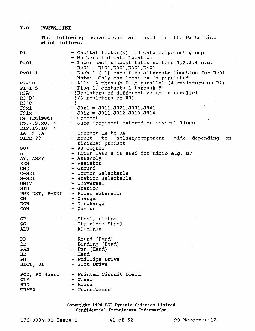
7.0 PARTS LIST
The following conventions are used in the Parts List which follows.
Rl
RxOl
RxOl-1
R2A"'D Pl-1)\5 R3AA R3ABA R3AC J9xl J91x R4 (Raised) R5,7,9,x03 > R12,15,18 > lA -> 3A SIDE??
90* u AY, ASSY RES GND C-SEL S-SEL UNIV STN PWR EXT, P-EXT CH DCH COM
SP SS ALU
RD BD PAN HD PH SLOT, SL
PCB, PC Board CLR BRD TRAFO
- Capital letter(s) indicate component group - Numbers indicate location - Lower case x substitutes numbers 1,2,3,4 e.g.
RxOl - R101,R201,R301,R401 - Dash 1 (-1) specifies alternate location for RxOl
Note: Only one location is populated - AAD: A through Din parallel (4 resistors on R2} - Plug 1, contacts 1 through 5 -}Resistors of different value in parallel
}(3 resistors on R3) }
- J9xl = J911,J921,J931,J941 - J91x = J911,J912,J913,J914 - Comment - same component entered on several· lines
- Connect lA to 3A - Mount to solder/component side depending on
finished product - 90 Degree - Lower case u is used for micro e.g. uF - Assembly - Resistor - Ground - Common Selectable - Station Selectable - Universal - Station - Power extension - Charge - Discharge - Common
- Steel, plated - Stainless Steel - Aluminum
- Round (Head) - Binding (Head) - Pan (Head) - Head - Phillips Drive - Slot Drive
- Printed Circuit Board - Cl.ear - Board - Transformer
Copyright 1990 DSL Dynamic Sciences Limited Confidential Proprietary Information
176-0004-00 Issue 1 41 of 52 90-November-12

Parts List, sheet 1 of 5
Item 15-010-2020 DSL6629 Charger 115V/60Hz. complete
Item No:
17-721-0050 17-721-0040 17-650-0010 80-915-0010 16-150-0010 70-111-0003 75-108-2201 68-223-1801 69-132-0003 59-314-1001 50-121-0200 69-132-0004 62-726-0020 75-606-3201 66-504-5001 25-237-0001 69-121-0002 75-406-0202 75-206-0101 66-333-6601 68-723-1802 70-132-0002 57-111-0005 66-263-4301 75-408-0203 75-208-0101 75-606-1101 75-106-2203 75-106-2202 88-820-0001
Description
AY, DSL6629 CHARGER BOARD AY, DSL6629 LED BOARD AY, CONTACT PLATE DSL66 •• FLOT LOWER HOUSING, DSL6629 COMPLETE UPPER HOUSING, DSL6629 COMPLETE BUMPER, RUBBER .5xl"DIA BLACK SCREW, 8-32xl/2 11 SS PH PAN HOOK-UP WIRE, BLK 18AWG(l6x30) TUBING, HEAT-SHRINK 3/16 11 BLACK SWITCH, ROCKER lOA 250V I/0 CIRCUIT BREAKER, THERMAL 2A TUBING, HEAT-SHRINK 1/4 11 BLACK CONNECTOR, BLOCK 2-TERMINAL SCREW, #6x5/8" TAPPING SS PH FERRULE, 7mm NON-INSUL 16AWG VARISTOR, RADIAL 4500A 130Vrms TUBING, PVC 20AWG CLEAR WASHER, LOCK #6 SS INTERNAL NUT, 6-32 x 1/4" FLATS SP or SS TERMINAL, #6 RING 22-18AWG CORD, POWER GRY 8'SJT 3x18 115 STRAIN RELIEF, .300 11 WIRE DIA TRANSF'R 150VA 115V 60Hz 42VCT DISCONNECT, FEMALE 16-14AWG WASHER, LOCK #8 SS EXT TOOTH NUT 8-32x 11/32" FLATS SP or SS SCREW, 6-32xl/4 11 SELF-CUT PH SCREW, 6-32x3/8 11 SS PH PAN SCREW, 6-32x3/8" SS PH FLAT NAME PLATE, DSL6629
1 1 4 1 1 4 8 1 0.1 1 1 0.,13 1 1 2 1 0.1
11 1 1 1 1 1 3 8 4 3
10 2 1
Copyright 1990 DSL Dynamic Sciences Limited Confidential Proprietary Information
Reference
Sheet 2 of 5 Sheet 4 of 5 Sheet 5 of 5
LOWER HOUSING Tl, BUMPER Sl, CBl Sl Sl CBl CBl
CONNECTOR BLOCK RVl & PWR CORD RVl RVl
GND STUD GND
PWR CORD Tl Tl SEC. Tl - IN/OUTSIDE Tl LED BOARD
UPPER HOUSING BACK OF UNIT
176-0004-00 Issue 1 42 of 52 90-November-12
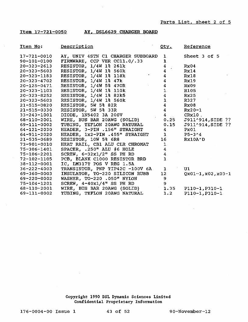
Item 17-721-0050 AY. DSL6629 CHARGER BOARD
Item No:
17-721-0010 90-101-0100 20-323-2613 20-323-5603 20-323-1183 20-323-4702 20-125-0471 20-323-1103 20-323-8252 20-323-5603 21-515-0820 21-515-0330 33-243-1001 68-110-2001 69-111-0002 64-121-2030 64-911-2020 21-535-0689 73-901-0010 75-306-1401 75-106-2201 72-102-1105 38-112-0001 36-222-4003 69-360-0003 69-220-0002 75-104-1201 68-110-2001 69-111-0002
Description
AY, UNIV 4STN Cl CHARGER SUBBOARD FIRMWARE, CCP VER CCll.0/.33 RESISTOR, 1/4W 1% 261k RESISTOR, 1/4W 1% 560k RESISTOR, 1/4W 1% 118k RESISTOR, 1/4W 1% 47k RESISTOR, 1/4W 5% 470R RESISTOR, 1/4W 1% llOk RESISTOR, 1/4W 1% 82k5 RESISTOR, 1/4W 1% 560k RESISTOR, 5W 5% 82R RESISTOR, 5W 5% 33R DIODE, 1N5402 3A 200V WIRE, BUS BAR 20AWG (SOLID) TUBING, TEFLON 20AWG NATURAL HEADER, 3-PIN .156" STRAIGHT HEADER, lx2-PIN .455" STRAIGHT RESISTOR, lOW 5% 6R8 HEAT RAIL, CBl ALU CLR CHROMAT SPACER, • 250 11 ALU #6 HOLE SCREW, 6-32xl/2" SS PH RD PCB, BLANK ClOOO RESISTOR BRD IC, LM317T POS V REG 1.5A TRANSISTOR, PNP TIP42C -lOOV 6A INSULATOR, T0-220 SILICON RUBB WASHER, T0-220 .050 11 NYLON SCREW, 4-40xl/4" SS PH RD WIRE, BUS BAR 20AWG (SOLID) TUBING, TEFLON 20AWG NATURAL
Parts List. sheet 2 of 5
1 1 4 4 4 4 4 1 4 1 4 4 4 0.25 0.15 4 1
16 1 4 4 1
1 12
9 9 1. 35 1.2
Reference
Sheet 3 of 5
Rx04 Rx14 Rxl8 Rx19 Rx09 R105 Rx25 R327 Rx08 Rx20-1 CRx10, J911"914,SIDE ?? J911"914,SIDE ?? PxOl P5-3"4 RxlOA''D
Ul Qx01-1,x02,x03-1
P110-1,P310-1 P110-l,P310-1
Copyright 1990 DSL Dynamic Sciences Limited Confidential Proprietary Information
176-0004-00 Issue 1 43 of 52 90-November-12

Parts List. sheet 3 of 5
Item 17-721-0010 AY, UNIV 4STN C1 CHARGER SUBBOARD
Item No:
72-102-1103 20-125-0272 20-125-0102 20-125-0681 20-125-0105 20-323-1004 20-125-0473 20-125-0104 20-125-0474 20-125-0103 20-125-0273 20-125-0151 23-111-0501 22-110-2682 20-323-4702 20-125-0472 20-125-0682 20-323-5601 20-323-1002 28-247-1104 28-336-1105 28-276-1100 28-277-1102 28-952-2104 33-232-1001 33-131-1001 36-111-1001 40-104-1401 63-121-4280 41-203-2001 41-203-1603 51-112-0001 64-911-2101 43-201-6401 48-120-0001 69-111-0001 52-546-0160 66-161-0001 46-211-0001 28-627-1107 28-647-3477
Description
PCB, BLANK ClOOO MAIN BOARD RESISTOR, 1/4W 5% 2k7 RESISTOR, 1/4W 5% lk RESISTOR, 1/4W 5% 680R RESISTOR, 1/4W 5% lM RESISTOR, 1/4W 1% lM RESISTOR, 1/4W 5% 47k RESISTOR, 1/4W 5% lOOk RESISTOR, 1/4W 5% 470k RESISTOR, 1/4W 5% lOk RESISTOR, 1/4W 5% 27k RESISTOR, 1/4W 5% 150R TRIMMER, 1-TURN PCB 500R RESISTOR, NW BUSSED lOSIP 6k8 RESISTOR, 1/4W 1% 47k RESISTOR, 1/4W 5% 4k7 RESISTOR, 1/4W 5% 6k8 RESISTOR, 1/4W 1% 5k6 RESISTOR, 1/4W 1% lOk CAPACITOR, MONO 20% 50V. luF CAPACITOR, TANT 10% 35v luF CAPACITOR, MONO 10% 200V lOpF CAPACITOR, MONO 20% 200V. OOluF CAPACITOR, MKT 2% 63V .luF DIODE, 1N4002 lA lOOOV DIODE, 1N4148 lOmA lOOV TRANSISTOR, NPN 2N3904 40V IC, 339 QUAD COMPARATER IC SOCKET 28-PIN TIN DUAL LEAF IC, 74HC373 OCTAL D-TYPE LATCH IC, 74HC259 8-BIT ADDR LATCH FUSE, CLIP 5mm PCB TYPE HEADER, 2x5-PIN .455 11 STRAIGHT IC, uPD78C10 MICRO-CONTROLLER CRYSTAL, 2-LEAD 11.0592MHz TUBING, TEFLON 22AWG NATURAL FUSE, 5x20mm 1.6A 250V FST QUICK CONNECT, MALE .25011 PCB TRANSDUCER, AUDIO QMB 70db 12V CAPACITOR, ELEC RAD 25V lOOuF CAPACITOR, ELEC RAD 50V 470uF
1 1 5 4 3 4
11 5 1 6 1 1 1 1 6
12 4 4 5 9 7 2 1 4 2
13 2 5 1 1 1 2 1 1 1 0.04 1 3 1 1 1
Copyright 1990 DSL Dynamic Sciences Limited Confidential Proprietary Information
Reference
R2 R3,x02 Rx16 R7,11,13 Rxll R9,10,12,x01,x03 R8,x22 R14 R15,17,x21 R4 R16 Rl R20 R5,6,x15 Rx07,x17,x23 Rx24 Rx12 R206,xl3 C2,4,11"'13,x01 C6,7,105,x03 C8,9 cs Cx02 CRl,2 CR3,x01,x02,x03 Ql,2 U2,x01 U4 us U6 Fl P4 U3 Yl (STICK TO U3) Yl (.225 11 LONG) Fl Pl-1"'3 LSl C3 Cl
SIDE?? SIDE?? SIDE?? SIDE??
176-0004-00 Issue 1 44 of 52 90-November-12

Parts List. sheet 4 of 5
Item 17-721-0040 AY, DSL6629 LED BOARD
Item No: Description QtL. Reference
20-125-0221 RESISTOR, l/4W 5% 220R 9 R21"29 46-111-0002 LED, ULTRA-RED/DIFF 3mm DIA 4 DSl,3,5,7 46-121-0002 LED, SUPER-GREEN 3mm DIA 4 DS2,4,6,8 46-131-0002 LED, YELLOW/DIFF 3mm DIA 1 DS9 72-102-1104 PCB, BLANK CBlOOO DISPLAY BRO. 1 68-525-0001 JUMPER, 8 11 LONG IO-CONDUCTOR 1 P3
Copyright 1990 DSL Dynamic Sciences Limited Confidential Proprietary Information
176-0004-00 Issue 1 45 of 52 90-November-12

Item 17-650-0010 AY, CONTACT PLATE DSL66 ••
Item No:
16-650-0100 17-680-0010 82-612-0020 69-250-0007 69-250-0008 75-700-2102 86-602-0001 86-502-0001 68-223-2401 75-748-0102 75-106-3201 75-406-0203 69-250-0006 75-706-0402 75-706-0401
Description
AY, CONTACT B-D-GRN PTO XD AY, CABLE HARNESS & THERMISTOR CONTACT PLATE, DSL FLOATING WASHER, #6 FLAT FIBRE GREY WASHER, #6 FLAT FIBRE BLACK RIVET, TUB .142x.375" BRASS OV THERMAL JOINT COMPOUND, WHITE HOT GLUE, WHITE HOOK-UP WIRE, BLK 24AWG (7x32) RET. RING, SELF-SEAT 3/16 11 EXT SCREW, 6-32x5/811 SS PHIL PAN WASHER, LOCK #6 SS SPLIT WASHER, #6 EXTRUDED FIBRE GUIDE POST, .250 11 DIA ALU GUIDE POST, .375 11 DIA ALU
Parts List. sheet 5 of 5
2 1 1 1 1 1 0.1 0.1 0.2 2 2 2 1 1 1
Reference
POS/NEG,FLOATING RED+,BLK-,BLUE
RIVET RIVET ADD WASHER THERM SEAL RIVET THERM .015 11 GAP
BOTTO~ GUIDE BOTTOM CENTER
Copyright 1990 DSL Dynamic Sciences Limited Confidential Proprietary Information
176-0004-00 Issue 1 46 of 52 90-November-12

8.0 DRAWINGS
The following pages contain the drawings listed
Block Diagram - Model 6629 Charger
Schematic Diagram - Model 6629 Charger
Assembly Drawing - Main PCB
Assembly Drawing - Resistor Board PCB
Copyright 1990 DSL Dynamic Sciences Limited Confidential Proprietary Information
below:
1 sheet
1 sheet
1 sheet
1 sheet
176-0004-00 Issue 1 47 of 52 90-November-12

This page left blank intentionally.
Copyright 1990 DSL Dynamic Sciences Limited Confidential Proprietary Information
176-0004-00 Issue 1 48 of 52 90-November-12

BLOCK DIAGRAM OF DSL 6629 BATTERY FAST-CHARGER
~oNE VAC )
AUXILIARY CIRCUIT
REF# 20 ---> 22 >
24-1 --> 24-2 --> 24-3 -> 24-4 ->
<- 78
REFERENCE#
20 Reset 22 24 78
42 44 48
Overload Code Selector Transducer
V Sense Battery Temperature Reverse Polarity
62 Fast Charge 64 Trickle Charge 68 Reverse Load
72 74 76
Charge LED Ready LED Power LED
M I
REF# <-- 42-1 <- 44-1 <-- 48-1
62-1 -> 64-1 -> 68-1 ->
<- 42-2
DRIVER 1
+
t--__ _
<-- 44-2 + <-- 48-2 DRIVER
62-2 --> 2 64-2 -> 68-2 -->
C <- 42-3 R 0
c 0 N T R 0 L L E R
<- 44-3 <-- 48-3
62-3 -> 64-3 -> 68-3 ->
<-- 42-4 <- 44-4 <- 48-4
62-4 -> 64-4 -> 68-4 ->
DRIVER 3
DRIVER 4
+
+
0 0 0 0
o Charge Charge Charge Charge Power
76 72-1 74-1 72-2 74-2
0
Ready 0
Ready 0
Ready
72-3 _______ ___,
74-3 72-4
t----74-4
0
Ready
Copyright 1990 DSL Dynamic Sciences Limited Confidential Proprietary Information
176-0004-00 Issue 1 49 of 52 90-November-12

THtS DRAWING IS THE EXCt.USWE PROPERTY OF DSL DYNAMIC SCIENCES LIMITED (DSt.) AHO SHALL NO~ USED, COPIED NOft TRANSMm'l!D TO ANY OTHER PARTY WITHOUT THE PRtOR EXPRESS WR N CONSENT OF DSL UPON EVALUATION OR OTHER USUAGE AS AUTHORIZED IN WRmNG BY DSL, THIS DRAWING MUST BE RETURNED TO DSL
UNLESS OTHERWISE OWNBY
DSL DYNAMIC SCIENCES LIMITED SPECIFIED DIMENSIONS CHECKER
ARE IN INCHES VANCOUVER O MONTREAL O DECIMAL .XX ± APPD
.xxx ± MATERIAL TITLE RESISTOR BOARD PCB ASSY DWG FRACTION ± 2-' Ff'b §$ 113 ANGULAR ± MODEL 6629 CHARGER
DO NOT SCALE DWG
DRAWING STATUS FINISH DRAWING NO. (PART NO.) REV
A PROTO 0 PILOT 0 (DWO NO.)
PROO 0 RELEASE DATE I SCALE ISH I OF I
$ ~ x
?I:) w
~' - 7~ C) I
;II;) -0 I -
• •
• ' • • ""
:1 • • • " •
I • •
• I J e~,0·': $ f\~:~ • • •
• •
~~ . o'' ~,~ • "
fl •
",~ .
.. .. • ..
0 0 -------------- ··-·· .. -----...