Model 610 Broadcast Audio Delay -...
22
i Model 610 Broadcast Audio Delay Revision 1.4, 9 July, 1997 Symetrix part number: 530610 Subject to change at our whim and fancy, without notice. Copyright 1996, Symetrix, Inc. All rights reserved. Symetrix is a registered trademark of Symetrix, Inc. Orban and OPTIMOD are registered trademarks of AKG Acoustics, Inc. Mention of third-party products is for informational purposes only and constitutes neither an endorsement nor a recommendation. Symetrix assumes no responsibility with regard to the performance or use of these products. Under copyright laws, no part of this manual may be reproduced or transmitted in any form or by any means, electronic or mechanical, including photocopying, scanning, recording or by any information storage and retrieval system, without permission, in writing, from Symetrix, Inc. User’s Guide Symetrix, Inc. 14926 35th Ave West Lynnwood, WA 98037 USA Voice: (425) 787-3222 Fax: (425) 787-3211 Email: [email protected] Website: www.symetrixaudio.com
Transcript of Model 610 Broadcast Audio Delay -...

i
Model 610Broadcast Audio Delay
Revision 1.4, 9 July, 1997
Symetrix part number: 530610
Subject to change at our whim and fancy, without notice.
Copyright 1996, Symetrix, Inc. All rights reserved.
Symetrix is a registered trademark of Symetrix, Inc.
Orban and OPTIMOD are registered trademarks of AKG Acoustics, Inc.
Mention of third-party products is for informational purposes only andconstitutes neither an endorsement nor a recommendation. Symetrixassumes no responsibility with regard to the performance or use of theseproducts.
Under copyright laws, no part of this manual may be reproduced ortransmitted in any form or by any means, electronic or mechanical,including photocopying, scanning, recording or by any informationstorage and retrieval system, without permission, in writing, fromSymetrix, Inc.
User's Guide
Symetrix, Inc.14926 35th Ave West
Lynnwood, WA 98037 USAVoice: (425) 787-3222
Fax: (425) 787-3211Email: [email protected]
Website: www.symetrixaudio.com

ii
Contents1 Introduction 1
2 Safety Information 2
Operator safety summary 2
Other safety information 3
3 Summary Product Description 4
Front panel view 4
Rear panel view 5
4 Installation 6
AC line connection 6
Mounting in an equipment rack 6
Audio input connections 7
Audio output connections 7
Typical system block diagram 7
Remote indicator and control interface connections 7
5 Operation 8
Operational Status 8
The INPUT HEADROOM(dB) display 8
The START DELAY button 9
The EXIT DELAY button 9
The DELAY TIME (SECONDS) display 10
Lamp Functions 10
6 Troubleshooting 11
Solutions to common problems 11
Less common problems 11
7 Warranty and Service 12
The Symetrix 610 Limited Warranty 12
Servicing the 610 13
Return authorization 13
In-warranty repairs 13
Out-of-warranty repairs 13
Appendix A Specifications 14
Architects and engineers specifications 14
Technical specifications 14
Appendix B Remote Indicator and Control Interface Wiring 15
Remote panel switch pinouts 15
Remote panel LED pinouts 15
Cart machine start opto isolator pinouts 15
Typical remote panel switch wiring 16
Typical remote panel LED wiring 16
Appendix C Default Configuration 17
START DELAY and EXIT DELAY speed 17
Full memory dump or 3.75 second dump 17
Default configuration programming 18

Page 1
IntroductionCongratulations on your decision to use a Symetrix model 610 Broadcast Audio Delay. The 610has been designed to give broadcasters unequaled performance combined with ease of use andreliability. This manual will guide you through the installation and operation of the 610, andprovide valuable tips on how to interface with other equipment in your studio or control room.
The 610 gives the host or producer of a talk show the power to prevent the broadcast of unwantedprofanities or comments from telephone callers. As the program begins, the 610 gradually andunobtrusively delays or "stretches out" the program until 7 1/2 seconds of 14kHz bandwidthstereo audio is stored in memory. When a person on the telephone line says something the host orproducer does not think appropriate for the broadcast, he or she presses the DUMP PROFANITYbutton and the memory is cleared, thereby preventing the unwanted audio from reaching theairwaves. Meanwhile, the host releases the offending caller from the telephone line and proceedswith the program. After the DUMP PROFANITY button has been pressed, the 610 automaticallybegins to stretch (time expand) the program audio again until the full 7 1/2 second delay isattained.
Several minutes in advance of the end of the talk show, the host or producer presses the EXITDELAY button and the 610 begins to time compress the program audio until there is nothing leftin the 610's memory (zero seconds delay). At this point the program is back in "real time" and the610 automatically removes itself from the signal path.
A unique feature of the 610 is the COUGH button, which allows the host to make impromptuinterruptions in the program for up to 7 1/2 seconds while keeping the audience unaware of thebreak. When the COUGH button is pushed, the 610 plays from memory while the button is heldin. As soon as the button is released, the 610 automatically begins to refill the memory. The hostcan cough, have a quick drink of water, or make a comment to the producer or engineer withoutany perceptible program interruption.
The 610 uses the latest in delta-sigma conversion technology coupled with advanced digitalsignal processing (DSP) algorithms. This combination produces a product that meets or exceedsthe highest broadcast standards in terms of low noise, low distortion, and superb signal process-ing.
The 610's logical, easy to use control panel holds no hidden surprises. The product is easy tolearn and simple to use. In the sections that follow you'll find information on installation, opera-tion, and specific applications of the 610. We follow this with a troubleshooting guide, warrantyand service information, and detailed specifications.
As with all Symetrix products, the 610 has been designed and built to the highest standards of thebroadcast industry. Our company is committed to excellence in product design, manufacturing,and service. Please do not hesitate to contact us with your questions or comments.
1

Page 2
Safety InformationOperator safety summary
The information in this summary is intended for persons who operate the equipment as well asrepair personnel. Specific warnings and cautions are found throughout this manual wherever theymay apply; they do not appear in this summary.
The notational conventions used in this manual and on the equipment itself are described in thefollowing paragraphs.
Equipment markings
The lightning flash with arrowhead symbolwithin an equilateral triangle is intended toalert the user of the presence of uninsulated"dangerous voltage" within the product'senclosure that may be of sufficient magni-tude to constitute a risk of electric shock topersons.
The exclamation point within an equilateraltriangle is intended to alert the user of thepresence of important operating and mainte-nance (servicing) instructions in the litera-ture accompanying the 610 (i.e. thismanual).
CAUTION
WARNING:
ATTENTION: RISQUE DE CHOC ELECTRIQUENE PAS OUVRIR
S’adresser a un reparateur compétent.
THIS EQUIPMENT TO RAIN OR MOISTUREELECTRIC SHOCK DO NOT EXPOSETO REDUCE THE RISK OF FIRE OR
No user serviceable parts inside. Refer servicing to qualified service personnel.Il ne se trouve a l’interieur aucune piece pourvant entre reparée l’usager.
DO NOT OPENRISK OF ELECTRIC SHOCK
Caution
To prevent electric shock, do not use the polarized plug supplied with the 610 with any extensioncord, receptacle, or other outlet unless the blades can be fully inserted to prevent blade exposure.
Terms
Several notational conventions are used in this manual. Some paragraphs may use Note, Caution,or Warning as a heading. These headings have the following meaning:
Note Identifies information that needs extra emphasis. A Note generally supplies extrainformation to help you to better use the 610.
Caution Identifies information that, if not heeded, may cause damage to the 610 or otherequipment in your system.
Warning Identifies information that, if ignored, may be hazardous to your health orthat of others.
In addition, certain typefaces and capitalization are used to identify certain words. These are:
CAPITALS Controls, switches or other markings on the 610's chassis.
Boldface Strong emphasis.
2

Page 3
Other safety information
Power source
This product is intended to operate from a power source that does not apply more than 255Vrmsbetween the power supply conductors or between either power supply conductor and ground. Aprotective ground connection, by way of the grounding conductor in the power cord, is essentialfor safe operation.
Grounding
The chassis of this product is grounded through the grounding conductor of the power cord. Toavoid electric shock, plug the power cord into a properly wired receptacle before making anyconnections to the product. A protective ground connection, by way of the grounding conductorin the power cord, is essential for safe operation.
Danger from loss of ground
If the protective ground connection is lost, all accessible conductive parts, including knobs andcontrols that may appear to be insulated, can render an electric shock.
Proper power cord
Use only the power cord and connector specified for the product. Use only a cord that is in goodcondition.
Proper fuse
The fuse is mounted internally and is not considered user serviceable. The fuseholder acceptsAmerican sized fuses (1/4 inch diameter) or European sized fuses (5mm diameter). For 117VACoperation, the correct value is 1/2A, 250VAC, fast blowing (Bussman type AGC). For 230VACoperation, the correct value is 1/4A, 250VAC, slow blowing (Bussman type MDL or GDC).
Operating location
Do not operate this equipment under any of the following conditions: explosive atmospheres, inwet locations, in inclement weather, improper or unknown AC mains voltage, or if improperlyfused.
Stay out of the box
To avoid personal injury or injury to others, do not remove the product covers or panels. Do notoperate the product without the covers and panels properly installed.

Page 4
INACTIVE ACTIVE
BYPASSOPERATE
AUDIO DELAYBROADCAST
016
START DELAYEXIT DELAYINPUT HEADROOM (dB)STATUS
036912151824 2130 27DELAYDELAY
33
3
� The STATUS button places the 610 in either BYPASS or OPERATE modes. In BYPASS modethe incoming signals are directly routed (via relays) to the 610's outputs, thereby bypassing anyinternal circuitry. In BYPASS mode, the front panel and remote controls have no effect on theoperation of the 610. In OPERATE mode, the incoming signals are processed through the 610'sanalog and digital circuitry, and all front panel and remote controls are fully functional.
� The INPUT HEADROOM(dB) LED display indicates the headroom in decibels before theonset of input clipping. The display indicates the higher (i.e. worst case) of the two incomingstereo channels.
� The EXIT DELAY button initiates the gradual reduction of delay time. Once this button ispressed, assuming no other control button is subsequently pressed, the 610 will proceed toincrementally reduce delay time until a zero delay is achieved.
� The START DELAY button initiates the gradual increase of delay time. Once this button ispressed, assuming no other control button is subsequently pressed, the 610 will proceed toincrementally increase delay time until a 7 1/2 second delay is achieved.
Summary Product DescriptionThis chapter provides a basic overview of the 610 by describing the input and output connections,power connection, operating controls, front panel LED indicators, and the remote indicator andcontrol interface. Use this information to acquaint yourself with the product. Chapter 4 (Installa-tion) gives details on installing the 610 in your system and Chapter 5 (Operation) gets intospecific applications and uses of the 610 in detail.
Front panel view (left)
START DELAY button
EXIT DELAY buttonSTATUS (BYPASS/OPERATE) button
INPUT HEADROOM LED display
Front panel view (right)
COUGH buttonDUMP PROFANITY button
DELAY TIME LED displayAbstract but deeply meaning-ful graphic symbol (ADMGS)
DELAY TIME (SECONDS)COUGH DUMP PROFANITY
7.576.55.554.53.5 42.5 321.51.50 6

Page 5
� Pressing the COUGH button mutes the incoming signal while allowing the output signal to play(uninterrupted) from the 610's memory. The 610 will continue to play from memory for so longas the button is pressed. When the COUGH button is released, the 610 resumes recording intomemory and "splices out" the silence created while the button was pressed. The 610 then beginsto rebuild the delay time used while the COUGH button was pressed. The listener will be awareof a program interruption if and only if the button is held for a time exceeding the time inmemory.
� Assuming the memory contains the maximum 7 1/2 seconds of audio, and the 610 is config-ured for full memory dump, pressing the DUMP PROFANITY button erases the entire memory.The 610 proceeds to splice back together everything except the erased audio. If no other controlbutton is subsequently pressed, the 610 will proceed to incrementally increase delay time until a7 1/2 second delay is again achieved. See Chapter 5 and Appendix C for details on the 3 3/4second (partial dump) option and a more detailed explanation of the DUMP PROFANITYfunction.
� The AC INPUT connector accepts nominal AC power sources of 117 volts or 230 volts [seeAppendix A (Specifications) for voltage tolerance ranges]. See chapter 4 (Installation) for detailson the detachable (IEC) power cable.
� The REMOTE INDICATOR AND CONTROL INTERFACE provides a way to connect to auser supplied remote control and/or indicator panel. See Appendix B for details.
� The LEFT OUTPUT and RIGHT OUTPUT audio connectors are electronically balanced, linelevel, low impedance outputs. Pin 1 is ground. Pin 2 is high. Pin 3 is low.
� The NOMINAL OPERATING LEVEL select button matches the 610's input sensitivity to thenominal output level of the device (normally the on-air console) driving the 610. The two optionsare +8dBu and +4dBu. See Chapter 4 (Installation) for further discussion of signal levels.
� The LEFT INPUT and RIGHT INPUT audio connectors are electronically balanced, line level,bridging inputs. Pin 1 is ground. Pin 2 is high. Pin 3 is low.
AC INPUT
610 BROADCAST AUDIO DELAY LEFT OUTPUT RIGHT OUTPUT
REMOTE INDICATOR ANDCONTROL INTERFACE
20W MAXIMUM
THIS UNIT CONTAINS NOUSER SERVICEABLE PARTS.
MANUFACTURED IN THE USA BY
AC INPUT connectorREMOTE INDICATOR AND CONTROL INTERFACE RIGHT OUTPUT audio connector
Rear panel view (right)
ESSPRESSPR
-10 dBV+4 dBu
LEVEL (dB)
RIGHT INPUTNOMINAL OPERATING
LEFT OUTPUT RIGHT OUTPUT
REMOTE INDICATOR ANDCONTROL INTERFACE
.
Y LEFT INPUT
NOMINAL OPERATING LEVEL select buttonLEFT INPUT audio connector RIGHT INPUT audio connector
Rear panel view (left)
LEFT OUTPUT audio connector

Page 6
InstallationBefore you plug the 610 into a wall socket, carefully read the information in the following
chapter.
AC Line connection
A sticker on the right end of the unit (as viewed from the front) indicates the nominal voltagesetting for the unit as it left the Symetrix factory. If this does not correspond to the voltage settingfor your locale then do not attempt to apply power to the 610. Instead, return the unit to your localSymetrix distributor for modification.
The 610 is shipped from the Symetrix factory with a detachable AC power cable (IEC standard)included. Depending on the intended destination, the power plug is either the US type (intendedfor 117VAC use), or the Europlug type. If the power cable's plug is not right for your locale, thenplease contact your local Symetrix distributor for the proper cable.
Once you have determined that the 610's operating voltage matches that of your locale and you areready to begin, follow these steps:
1 Plug the socket end of the power cable into the recessed AC power receptacle on the backof the 610.
2 Plug the other end of the power cable into a three-hole grounded outlet or power strip.
WARNING The 610 is intended to be electrically grounded. It has been provided with athree-wire grounding plug - a plug that has a third (grounding) pin. This plug will fit onlya grounded AC outlet. This is a safety feature. If you are unable to insert the plug into theoutlet, contact a licensed electrician to replace the outlet with a properly grounded outlet.Do not defeat the purpose of the grounding plug!
Mounting in an equipment rack
The 610 occupies one rack space (1U) in a standard equipment rack with a width of 19" (48.3cm),a depth of 7.5"(19.1cm), and a height of 1.75"(4.45cm). Allow at least 4"(10.16cm) behind theunit for the protrusion of connectors. We recommend you take care not to mount the 610 next todevices that emit large electromagnetic fields, such as audio power amplifiers. To do so maycomprise the noise performance of the 610. The 610 has been designed to conform to mechanicalguidelines as described in EIA Standard RS-310-C and IEC Recommendation 297.
Audio input connections
The 610's audio input connections are via standard female XLR jacks located on the rear panel.For optimum system performance we recommend that the 610 be connected to balanced signalsources. If this is not practical in your situation, then you may connect to unbalanced sources. Thefollowing diagram illustrates recommended cable wiring practices.
4
13
2
Male XLR
Male XLRPin 1=GroundPin 2 = HighPin 3 = Low
12
3
Pin 3 = LowPin 2 = HighPin 1=Ground
21
3
TIP
RINGSLEEVE
Sleeve = GroundRing = LowTip = High
Male 1/4" Tip-Ring-Sleeve Plug
Female XLRPin 1=Ground
Pin 3 = LowPin 2 = High
Analog Source 610 Analog Input

Page 7
Typical system block diagram
In most broadcast applications it is recommended that the 610 be connected between the station'son air console and the station's audio processing equipment. In other words, the console's mainstereo (or mono) output bus should connect to the 610's inputs, and the 610's outputs should feedthe "down stream" signal processing. As discussed in Chapter 5 (Operation), the 610 will auto-matically remove itself from the signal path when not in use.
Input Output
Output Input
Signal Levels
The 610 has been designed to operate at standard nominal broadcast signal levels of either 0VU =+4dBu or 0VU = +8dBu. The 610's rear panel NOMINAL OPERATING LEVEL button allowsyou match the 610 to either of these standards. If your console's nominal output level is lower thanthe +4dBu standard then you may wish to use a line amplifier to boost your input to the standardlevel. If you choose operate the 610 below standard line levels you may notice some decrease in thesignal to noise ratio at the output of the 610.
Audio output connections
The 610's audio output connections are via standard female XLR jacks located on the rear panel.For optimum system performance we recommend that the 610 be connected to balanced devices. Ifthis is not practical in your situation, then you may connect to unbalanced devices. The followingdiagram illustrates recommended cable wiring practices.
76 6.5 7.5
DELAY TIME (SECONDS)
54 4.53 3.52 2.51 1.5.50
DUMP PROFANITYCOUGH
5.5
START DELAYEXIT DELAY
039 61521 1827 2433 30 12
INPUT HEADROOM (dB)STATUS
ACTIVEDELAYDELAY
OPERATEBYPASS
INACTIVE
106BROADCASTAUDIO DELAY
31
2
TIP
Pin 3 = LowPin 2 = HighPin 1=GroundMale XLR
Tip = HighMale 1/4" Tip-Ring-Sleeve Plug
RINGSLEEVE
Sleeve = GroundRing = Low
32
12
3
Pin 2 = HighPin 3 = Low
Pin 1=GroundFemale XLR
Pin 1=GroundFemale XLR
1
Pin 3 = LowPin 2 = High
610 Output Destination device input

Page 8
5 OperationThis section describes in detail the 610's front panel controls and LED indicators.
Operational status
The STATUS button places the 610 in either BYPASS or OPERATE modes. In BYPASS modethe incoming signals are directly routed (via relays) to the 610's outputs, thereby bypassing anyinternal circuitry. In BYPASS mode the front panel and remote controls have no effect on theoperation of the 610. In OPERATE mode, when the delay is active, the incoming signals areprocessed through the 610's analog and digital circuitry, and all front panel and remote controlsare fully functional.
It is recommended that the STATUS button remain in the OPERATE (inward) position at alltimes. Typically, the 610 would be placed in the BYPASS mode only if the unit were to malfunc-tion. By design, two circumstances force the 610's audio bypass relays to route the incomingsignal directly to the 610's output. The first being loss of mains (AC) power to the 610 and thesecond being the normal operational function of EXIT DELAY (explained in detail below). Oncethe 610 has achieved zero time delay as a result of the EXIT DELAY button being pressed, theaudio bypass relays automatically remove the 610 from the signal path until the START DELAYbutton is pressed.
There are two LED's associated with the STATUS button. The LED to the left of the button,labeled DELAY INACTIVE, lights whenever the 610 has been forced to a bypass state. This canhappen automatically as a result of the EXIT DELAY function or manually as a result of movingthe STATUS button to the BYPASS position.
The LED to the right of the STATUS button, labeled DELAY ACTIVE, lights whenever the 610has been forced to operational status. This happens only as a result of the START DELAYfunction (explained in detail below).
INPUT HEADROOM (dB) display
The INPUT HEADROOM (dB) LEDs indicate the headroom in decibels before the onset of inputclipping. The display indicates the higher (i.e. worst case) of the two incoming stereo channels.While the 610 has no front panel input level control, a rear panel OPERATING LEVEL button isprovided (see discussion below), allowing you to select between nominal +4dBu and +8dBuoperating levels. Whatever your input levels are, fine adjustment of the input signal must be doneahead of the 610 (typically with the master buss control fader of the broadcast console).
The incoming signal level should be adjusted so that at least 6dB of headroom is maintained atall times. As digital devices go, the 610 is very quiet. Therefore, to ensure against any possibilityof clipping, you may wish to decrease input levels even further and operate with as much as 12dBof headroom.

Page 9
The START DELAY button
The START DELAY button initiates the gradual increase of delay time. When a radio talk showis to begin, the first action for the operator of the 610 is to press the green START DELAYbutton. Pressing the START DELAY button switches the 610 out of hard-wire bypass. Once thislighted button has been pressed, it's light will blink for as long as delay time is increasing. TheDELAY TIME LED display on the right end of the 610's front panel displays the amount of timein memory at any given instant. From a starting point of zero delay time, the amount of time thatit takes to achieve the maximum 7 1/2 second delay depends upon the 610's default configurationsetting (see Appendix C for details). Once the START DELAY button is pressed, assuming noother control button is subsequently pressed, the 610 will proceed to incrementally increase delaytime until a 7 1/2 second delay is achieved.
The EXIT DELAY button
The EXIT DELAY button initiates the gradual decrease of delay time. Several minutes in ad-vance of the end of a radio talk show, the operator of the 610 must press the yellow EXIT DE-LAY button. Once this lighted button is pressed, its light will blink as long as delay time isdecreasing. The DELAY TIME LED display on the right end of the 610's front panel displays theamount of time in memory at any given instant. Assuming that the delay is at the maximum of 71/2 seconds, the amount of time that it takes to reduce the delay time to zero seconds dependsupon the 610's default configuration setting (see Appendix C for details). Once the EXIT DELAYbutton is pressed, assuming no other control button is subsequently pressed, the 610 will proceedto incrementally decrease delay time until a zero delay time has been reached. Once zero delayhas been reached, the DELAY INACTIVE LED lights and the 610's audio bypass relays revert tothe bypass position.
The COUGH button
The COUGH button allows the host to make impromptu interruptions in the program for up to 71/2 seconds (or the maximum amount of time in memory, whichever is less) while keeping theaudience unaware of the break. When the COUGH button is pushed and held in, the 610 playsfrom memory and mutes incoming audio. As soon as the button is released, the 610 resumesrecording into memory and "splices out" the silence created while the audio was muted. The 610then begins to rebuild the delay time used while the COUGH button was pushed. The host cancough, have a quick drink of water, or make a comment to the producer or engineer without anyperceptible program interruption. If the COUGH button is pressed for an amount of time exceed-ing the amount of time in memory, the result will be muted output audio (dead air).
The DUMP PROFANITY button
The DUMP PROFANITY button should be pressed as soon as an unwanted comment is heard.Once pressed, the audio in memory is instantly erased. If memory has built up to the full 7 1/2seconds then the 610 automatically "splices" around the erased audio so the audience hears nodead air. If less than the full 7 1/2 seconds (2 seconds, for example) have accrued in memory atthe time the button is momentarily pressed, then the two seconds are erased and the program isnow on-the-air at real time. Please understand that if the talk show host has not given the 610time to build up to 7 1/2 seconds of delay when he momentarily hits the DUMP PROFANITYbutton an obscenity may get on the air.
Units with Version 1.05 software allow the host extra protection in the form of muting if he
Page 10
purposely holds down the DUMP PROFANITY button. Holding down the button would erasethe two seconds from memory and mute the output of the 610 until the DUMP PROFANITYbutton is released. This provides a "panic button" function for use if all hell breaks loose. Themuting function does not activate when the DUMP PROFANITY button is pushed and quicklyreleased.
After a DUMP PROFANITY command the 610 automatically reenters the START DELAY modeand the delay memory begins accruing until the full 7 1/2 seconds are achieved.
Alternatively, the 610 can be set up so that only 3 3/4 seconds of memory are deleted the firsttime the button is pushed, thereby maintaining a 3 3/4 second reserve. This allows the host tobring another caller on air right away without having to wait for the memory to build up fromzero. As in the case of the full 7 1/2 second dump, if the 610 has accrued only two seconds inmemory when the DUMP PROFANITY button is pushed, the host will have only two seconds ofprotection and the program will be on-the-air at real time. The 610 offers the host extra protectionin the form of muting if he purposely holds down the DUMP PROFANITY button. Holdingdown the button would erase the two seconds from memory and mute the output of the 610 untilthe DUMP PROFANITY button is released. This provides a "panic button" function for use ifthings get too crazy. The muting function does not activate when the DUMP PROFANITYbutton is pushed and quickly released.
See Appendix C (Default Configuration) for details on how to select between full memory dumpor partial (3 3/4 second) dump.
The DELAY TIME (SECONDS) display
As explained on the previous page, the DELAY TIME LED display indicates the time duration ofthe program audio in the 610's memory at any instant. If the 610 has been manually placed inBYPASS mode, or if the delay memory is zero seconds as a result of the EXIT DELAY function,all DELAY TIME LEDs will be off. The display is calibrated in .5 second intervals from zero to 71/2 seconds.
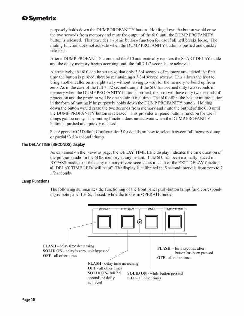
Lamp Functions
The following summarizes the functioning of the front panel push-button lamps (and correspond-ing remote panel LEDs, if used) while the 610 is in OPERATE mode.
COUGH DUMP PROFANITYSTART DELAYEXIT DELAY
FLASH - delay time decreasingSOLID ON - delay is zero, unit bypassedOFF - all other times
FLASH - delay time increasingOFF - all other timesSOLID ON- full 7.5seconds of delayachieved
SOLID ON - while button pressedOFF - all other times
FLASH - for 5 seconds after button has been pressedOFF - all other times

Page 11
6 TroubleshootingSolutions to common problems
There is no output signal.
Check the AC power connections to the 610.
Check input and output cables and connections.
Determine that there really is a signal coming from the source and that it is getting to the 610.
Distortion in the digital output signal.
Check the input signal. Is it overdriving the 610's input? If so, the INPUT HEADROOM displayshould indicate so.
Is the incoming signal already distorted? Listen "up stream" from the 610 (or manually place theunit in BYPASS mode) to determine that you are feeding it a clean signal.
Buzz in the output
Check input and output connector wiring.
Check for ground loops between interconnected system equipment.
Are all system components on the same AC ground?
Noise (hiss)
Check input signal levels and input level control settings. The input may be too low in level. Ifso, boost the signal from your console or input source.
Is the input signal already noisy? Listen "up stream" from the 610 to determine if you are feedingit a clean signal.
Less common problems
The 610 doesn't power up or doesn't respond properly.
Consult a qualified service technician or the Symetrix factory.
The 610 is not plugged in, but works great anyway.
Consult your doctor or therapist.

Page 12
7 Warranty and ServiceThe Symetrix 610 Limited Warranty
Symetrix, Inc. expressly warrants that the product will be free from defects in material andworkmanship for one (1) year. Symetrix's obligations under this warranty will be limited torepairing or replacing, at Symetrix's option, the part or parts of the product which prove defectivein material or workmanship within one (1) year from date of purchase, provided that the Buyergives Symetrix prompt notice of any defect or failure and satisfactory proof thereof. Productsmay be returned by Buyer only after a Return Authorization number (RA) has been obtained fromSymetrix. Buyer will prepay all freight charges to return the product to the Symetrix factory.Symetrix reserves the right to inspect any products which may be the subject of any warrantyclaim before repair or replacement is carried out. Symetrix may, at its option, require proof of theoriginal date of purchase (dated copy of original retail dealer's invoice). Final determination ofwarranty coverage lies solely with Symetrix. Products repaired under warranty will be returnedfreight prepaid via United Parcel Service by Symetrix, to any location within the ContinentalUnited States. Outside the Continental United States, products will be returned freight collect.
The foregoing warranties are in lieu of all other warranties, whether oral, written, express,implied or statutory. Symetrix, Inc. expressly disclaims any IMPLIED warranties, includ-ing fitness for a particular purpose or merchantability. Symetrix's warranty obligation andbuyer'sremedies hereunder are SOLELY and exclusively as stated herein.
This Symetrix product is designed and manufactured for use in professional and studio audiosystemsand is not intended for other usage. With respect to products purchased by consumers forpersonal, family, or household use, Symetrix expressly disclaims all implied warranties,including but not limited to warranties of merchantability and fitness for a particularpurpose.
This limited warranty, with all terms, conditions and disclaimers set forth herein, shall extend tothe original purchaser and anyone who purchases the product within the specified warrantyperiod.
Warranty Registration must be completed and mailed to Symetrix within thirty (30) days of thedate of purchase.
Symetrix does not authorize any third party, including any dealer or sales representative, toassume any liability or make any additional warranties or representation regarding this productinformation on behalf of Symetrix.
This limited warranty gives the buyer certain rights. You may have additional rights provided byapplicable law.
Limitation of Liability
The total liability of Symetrix on any claim, whether in contract, tort (including negligence) orotherwise arising out of, connected with, or resulting from the manufacture, sale, delivery, resale,repair, replacement or use of any product will not exceed the price allocatable to the product orany part thereof which gives rise to the claim. In no event will Symetrix be liable for any inciden-tal or consequential damages including but not limited to damage for loss of revenue, cost ofcapital, claims of customers for service interruptions or failure to supply, and costs and expensesincurred in connection with labor, overhead, transportation, installation or removal of products,substitute facilities or supply houses.

Page 13
Servicing the 610
If you have determined that your 610 requires repair services and you live outside of theUnited States please contact your local Symetrix dealer or distributor for instructions on how toobtain service. If you reside in the U.S. then proceed as follows.
Return authorization
At the Symetrix factory, Symetrix will perform in-warranty or out-of-warranty service on anyproduct it has manufactured for a period of five years from date of manufacture.
Before sending anything to Symetrix, please contact our Customer Service Department for areturn authorization (RA) number. The telephone number is (206) 787-3222, Monday throughFriday, 8AM (800 hours) through 4:30 PM (1630 hours), Pacific Time.
In-warranty repairs
To get your 610 repaired under the terms of the warranty:
1. Call us for an RA number.
2. Pack the unit in its original packaging materials.
3. Include your name, address, daytime telephone number, and a brief statement of the problem.
4. Write the RA number on the outside of the box.
5. Ship the unit to Symetrix, freight prepaid. We do not accept freight collect shipments.
Just do these five things, and repairs made in-warranty will cost you only one way freightcharges. We'll pay the return freight.
If you choose to send us your product in some sort of flimsy, non-Symetrix packaging, we'll haveto charge you for proper shipping materials. If you don't have the factory packaging materials,then do yourself a favor by using an oversize box. Wrap the unit in a plastic bag, surround it withbubble-wrap, and place it in the box surrounded by Styrofoam peanuts. Be sure there is enoughclearance in the box to protect the rack ears (you wouldn't believe how many units are returnedwith bent ears). We won't return the unit in anything but Symetrix packaging for which we willhave to charge you. Of course, if the problem turns out to be operator inflicted, you'll have to payfor both parts and labor. In any event, if there are charges for the repair, you will pay for thereturn freight. All charges will be COD unless you have made other arrangements (prepaid, Visaor Mastercard).
Out-of-warranty repairs
If the warranty period has passed, you'll be billed for all necessary parts, labor, packaging materi-als, and freight charges. Please remember, you must call for an RA number before sending theunit to Symetrix.

Page 14
Specifications
Architects and engineers specifications
The Broadcast Audio Delay shall be a stereo model whose output is delayed by as much as 7 1/2 seconds, thereby
allowing the operator to delete or "dump" unwanted audio The Broadcast Audio Delay shall occupy one rack space
(1U).
The inputs shall be active balanced bridging designs terminated with 3-pin XLR (AES/IEC standard wiring) female
jacks.
The outputs shall be active balanced designs terminated with 3-pin XLR (AES/IEC standard wiring) male jacks.
Overall frequency response shall be 20Hz to 14kHz, +1,-1dB, measured at +4dBu output. There shall be no more than
0.1% harmonic distortion measured under the following conditions: +4dBu input, +4dBm output, 7 1/2 second delay,
1000Hz test frequency.
When the unit is inoperative (either by loss of power, or via the BYPASS switch), the inputs and outputs shall be wired
together.
The Broadcast Audio Delay shall be capable of operating by means of its own built-in power supply connected to 117V
nominal AC (105 to 130V), 50/60 Hz and 230V nominal AC (207 to 253V), 50 Hz.
The Broadcast Audio Delay shall be a Symetrix, Incorporated model 610 BROADCAST AUDIO DELAY.
Architects and engineers specifications
Aappendix
AudioInputs Stereo, balanced bridgingOutputs Stereo, electronically balancedMaximum input level +22dBuMaximum output level +22dbu into 600 ohmsFrequency Response ±1dB, 20Hz-14kHz(in full delay)
-3.5dB@10kHz (building and exiting delay)Dynamic Range >80dBCrosstalk -55dB, +4dBu in, 20Hz-14kHzInput common mode rejection >60dB @ 1kHz
PhysicalInput connectors XLROutput connectors XLRPolarity Pin 2 highChassis size 1.75" H x 19" W x 7.5" D 4.45cm H x 48.3cm W x 19.1cm DShipping weight 8 lbs, 3.64kg
ElectricalPower 117VAC, nominal, 105-130VAC, 50-60Hz 230VAC, nominal, 207-255VAC, 50HzPower Consumption 15 watts, maximum
In the interest of continuous product improvement, Symetrix, Inc.reserves the right to alter, change, or modify these specificationswithout prior notice.
Copyright 1995, Symetrix, Inc. All rights reserved.
Technical specifications

Page 15
Bappendix
Remote Indicator and Control Interface WiringMany of the 610's most important control buttons and LED indicators may be wired to a usersupplied panel via the DB-25 multi-pin male connector on the 610's rear panel. In addition, acontrol current loop is provided for triggering optically isolated control input ports such as thosefound on cart machines. The current flows for 100 milliseconds every time the DUMP PROFAN-ITY button is pressed. The following tables detail the pin functions. The remote switches andLED indicators are electrically isolated from the switches and LEDs on the 610's front panel, buteffectively operate in parallel (i.e. simultaneously) with them.
Remote panel switch pinouts
Function Pin #
START DELAY 1
EXIT DELAY 4
DUMP PROFANITY 7
COUGH 10
Emergency BYPASS 14
Switch Common 13
Remote panel LED indicator pinouts
Function LED Cathode LED Anode
3.5 Seconds pin 3 pin 2
7 1/2 Seconds pin 6 pin 5
START DELAY pin 9 pin 8
EXIT DELAY pin 12 pin 11
DUMP PROFANITY pin 16 pin 15
COUGH pin 18 pin 17
BYPASS pin 20 pin 19
OPERATE pin 22 pin 21
Cart machine start opto isolator pinouts
Cathode Anode Ground
24 23 25
Note
The remote switches used should be high quality,momentary, single pole, push button type. Allswitches should return to pin #13, the switchcommon point.
Note
If the 610's STATUS has been forced to BYPASSmode by the front panel button, the only way toreturn the 610 to OPERATE mode is to depress thefront panel button. It cannot be done remotely.
Note
Internally within the 610, all LEDanodes connect to +10V and allLED cathodes to +.6V through 330ohm resistors.
Note
Pin 23 is internally connected to +10V through a330 ohm resistor. An internal open collector (pin24) returns current to ground. Current flows for 500milliseconds whenever the DUMP button is pressed.

Page 16
Typical remote panel switch wiring
Typical remote panel LED wiring
Note
The numbers within the circles refer to pins on the 610's rear panel DB-25 connector which islabelled REMOTE INDICATOR AND CONTROL INTERFACE.
COUGH
DUMP PROFANITY
EXIT DELAY
START DELAY
13
1
4
7
10
3 6 12 9 16 18
152 5 11 8 17
7.5SECONDS
3.5SECONDS
EXITDELAY
STARTDELAY
DUMPPROFANITY COUGH
Page 17
Cappendix
Default Configuration
START DELAY and EXIT DELAY speed
As discussed in Chapter 5, the START DELAY button initiates the gradual increase of delay timeand the EXIT DELAY button initiates the gradual decrease of delay time. You may select be-tween six different default configuation settings, the parameters of which are explained in detailbelow. Selecting the right algorithm will optimize the match between the 610 and your particularstation's programming needs.
The amount of time required to increase delay from zero to 7 1/2 seconds (and to decrease delayfrom 7 1/2 seconds to zero) may be partially program dependent (option 1 and 2), or non programdependent fixed times (option 3,4,5, and 6). The program dependent options have the advantageof potentially faster START and EXIT times. The fixed time options are advantageous in that theoperator knows exactly how long it will take to get to full delay and back to real time so thatbroadcast programming decisions can be made based upon known quantities.
The default configuration (as shipped from the factory), which is referred to as option #1 in thetable on page 19, is partially program dependent. It takes no longer than 5 minutes to increasefrom zero to 7 1/2 seconds delay (it can be much faster) and no longer than 5 minutes to go from7 1/2 seconds delay back to zero. We recommend you try this option first. It represents the besttrade-off in terms of audio quality versus speed.
Full memory dump or half memory (3 3/4 second) dump
As discussed in Chapter 5, the DUMP PROFANITY function may be configured in either of twoways: 1) when the DUMP PROFANITY button is pressed the entire content of the delay memoryis erased, or 2) when the DUMP PROFANITY button is pressed only 3 3/4 seconds of memory iserased. With the second option, assuming there is a full 7 1/2 seconds in delay memory, the hostcan dump one caller and put a second caller on air immediately, while the 610 automaticallycontinues to rebuild memory up to the 7 1/2 second maximum.
The default configuration (as shipped from the factory), which is referred to as option #1 in thetable on page 19, dumps only half of the memory each time the DUMP button is pressed. Asmentioned above, we recommend you try this option first. The two stage dump feature allows youto bring a new caller on air immediately after dumping a previous caller without having to waitfor the delay to build from zero.

Page 18
COUGH DUMP PROFANITYSTART DELAYEXIT DELAY
Default configuration programming procedure
The 610 default configuration is set from the front panel. The process involves placing the 610 inprogramming mode and selecting one of six possible configurations. It is not necessary to removethe unit from the equipment rack, or to remove the top cover to configure or re-configure. Theunit must be powered up and not in use. Please note - the 610 cannot be configured while opera-tional!
The configuration settings are nonvolatile. Should power go down, the last configuration settingis maintained. To program the 610 default configuration, proceed as follows:
Step #1 - Place 610 in BYPASS mode - Use the STATUS button at the left end of the 610 frontpanel to place the 610 in BYPASS mode.
Step #2 - Initiate Programming Mode - Press all four front panel lighted push buttons (EXITDELAY, START DELAY, COUGH, DUMP PROFANITY) and hold until all four lights come on(approximately five seconds). When you release the buttons all four will flash, indicating that the610 is in programming mode.
X X X X
Step #3 - Select Desired Option - While all four lights continue to flash, select your option bypressing a button or combination of buttons as indicated in the table on the following page. Theassociated light(s) flash to confirm your selection. After several seconds the light(s) will stopflashing, indicating that the 610 has left the programming mode.
Step #4 - Return 610 to OPERATE mode - Use the STATUS button at the left end of the 610front panel to place the 610 in OPERATE mode. The unit is now ready to operate.

Page 19
Option #
1 X
2 X
3 X
4 X
5 X X
6 X X
7 X X
8 X X
Notes:
Option 1 - Try this one first! This is the factory default option. It gives you the fastest increase/decrease time, and the ability to dump only half the memory each time the profanity button ispushed. This algorithm has minimal artifacts, i.e. it works well with music so you can playcommercials during the increase/decrease cycle.
Option 2 - Same as option 1 but with full memory dump.
Option 3 - Fixed 4 minute increase/decrease time with 1/2 memory dump. The 4 minute in-crease/decrease time gives you predictable build up/build down times but you may notice somepitch shifting of the audio with this option.
Option 4 - Just like option 3 but with full memory dump.
Option 5 - Fixed 5 minute increase/decrease time with 1/2 memory dump. The 5 minute increase/decrease results in minimal pitch shifting as compared to options 3 and 4.
Option 6 - Just like option 5 but with full memory dump.
Option 7 - Partially program dependent delay build and exit. A 3.5 second delay and full delaydump.
Option 8 - Fixed 3 minute delay build and exit. Has a 3.5 second delay time with full delaydump.
COUGH DUMP PROFANITYSTART DELAYEXIT DELAY
Partially program dependent increase/decrease time,1/2 memory (3 3/4 seconds) dump.
Partially program dependent increase/decrease time,full memory dump.
4 minute increase/decrease time, 1/2 memory ( 3 3/4seconds) dump.
4 minute increase/decrease time, full memory dump.
5 minute increase/decrease time, 1/2 memory (3 3/4seconds) dump.
5 minutes increase/decrease time, full memory dump.
Partially Program Dependant, 3.5 second maximumdelay
3.0 minute increase/decrease, 3.5 second maximumdelay

Page 20
Symetrix, Inc.14926 35th Ave. West
Lynnwood, WA, 98037-2303USA
Tel: (425) 787-3222Fax: (425) 787-3211
Website: http://www.symetrixaudio.comEmail: [email protected]