
MODEL 555SS - Hotsy
14
8.914-354.0 SERIAL NUMBER: DATE PURCHASED: FOR SALES AND SERVICE, PLEASE CONTACT: OPERATING INSTRUCTIONS AND PARTS MANUAL SPECIFICATIONS ● Pump Volume At Pump Head: 2.2 GPM/132 GPH ● Burner Type: Fuel Oil Fired, 214,300 BTU/Hr. ● Burner Fuel Pressure: 150 PSI ● Pump Pressure At Pump Head: 1300 PSI ● Machine Voltage: 115 VAC/60 Hz/1 Ph ● Total Machine Amperage: 20 Amps ● Machine Weight: 280 Lbs. ● Shipping Weight: 315 Lbs. ● Exhaust Stack Size: 8" ● Machine Dimensions: Length = 44", Width = 26", Height = 38" MODEL 555SS ® c L I S T E D ® Read instructions carefully before attempting to assemble, install, operate or service this pressure washer. Failure to comply with instructions could result in personal injury and/or property damage! NOTE: THIS MANUAL IS INTENDED FOR USE WITH THE FOLLOWING MODEL RELEASE ONLY: 555SS
Transcript of MODEL 555SS - Hotsy

8.914-354.0
SERIAL NUMBER:
DATE PURCHASED:
FOR SALES AND SERVICE, PLEASE CONTACT:
OPERATING INSTRUCTIONS AND PARTS MANUAL
SPECIFICATIONS● Pump Volume At Pump Head: 2.2 GPM/132 GPH● Burner Type: Fuel Oil Fired, 214,300 BTU/Hr.● Burner Fuel Pressure: 150 PSI● Pump Pressure At Pump Head: 1300 PSI● Machine Voltage: 115 VAC/60 Hz/1 Ph● Total Machine Amperage: 20 Amps● Machine Weight: 280 Lbs.● Shipping Weight: 315 Lbs.● Exhaust Stack Size: 8"● Machine Dimensions: Length = 44", Width = 26", Height = 38"
MODEL 555SS
®cLISTED ®
Read instructions carefully before attempting to assemble, install, operate or service this pressure washer. Failure to comply with instructions could result in personal injury and/or property damage!
NOTE: THIS MANUAL IS INTENDED FOR USE WITH THE FOLLOWING MODEL RELEASE ONLY: 555SS
8.914-354.0 • HOTSY 555SS • Rev. 03/11
OP
ER
ATO
R’S
MA
NU
AL
PR
ES
SU
RE
WA
SH
ER
4
INTRODUCTION & IMPORTANT SAFETY INFORMATION
Thank you for purchasing this Pressure Washer.
We reserve the right to make changes at any time without incurring any obligation.
Owner/User Responsibility:The owner and/or user must have an understanding of the manufacturer’s operating instructions and warnings before using this pressure washer. Warning information should be emphasized and understood. If the operator is not fl uent in English, the manufacturer’s instructions and warnings shall be read to and discussed with the operator in the operator’s native language by the purchaser/owner, making sure that the operator com-prehends its contents.
Owner and/or user must study and maintain for future reference the manufacturers’ instructions.
The operator must know how to stop the machine quickly and understand the operation of all controls. Never permit anyone to operate the engine without proper instructions.
This manual should be considered a permanent part of the machine and should remain with it if machine is resold.
When ordering parts, please specify model andserial number. Use only identical replacement parts.
This machine is to be used only by trained op-erators.
IMPORTANT SAFETY INFORMATION
READ OPERATOR’S MANUAL THOROUGHLY
PRIOR TO USE.
WARNING: To reduce the risk of injury, read operating instruc-tions carefully before using. 1. Read the owner's manual
thoroughly. Failure to follow instructions could cause malfunction of the machine and result in death, serious bodily injury and/or prop-erty damage.
2. Know how to stop the machine and bleed pressure quickly. Be thoroughly familiar with the controls.
3. Stay alert — watch what you are doing.
4. All installations must comply with local codes. Con-tact your electrician, plumber, utility company or the selling distributor for specifi c details. If your machine is rated 250 volts or less, single phase will be pro-vided with a ground fault circuit interrupter (GFCI). If rated more than 250 volts, or more than single phase this product should only be connected to a power supply receptacle protected by a GFCI.
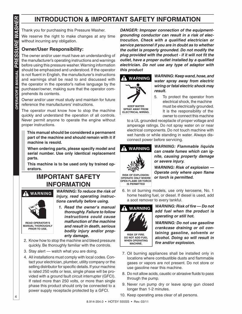
DANGER: Improper connection of the equipment-grounding conductor can result in a risk of elec-trocution. Check with a qualified electrician or service personnel if you are in doubt as to whether the outlet is properly grounded. Do not modify the plug provided with the product - if it will not fi t the outlet, have a proper outlet installed by a qualifi ed electrician. Do not use any type of adaptor with this product
WARNING
KEEP WATERSPRAY AWAY FROM
ELECTRICAL WIRING.
WARNING: Keep wand, hose, and water spray away from electric wiring or fatal electric shock may result.5. To protect the operator from electrical shock, the machine must be electrically grounded. It is the responsibility of the owner to connect this machine
to a UL grounded receptacle of proper voltage and amperage ratings. Do not spray water on or near electrical components. Do not touch machine with wet hands or while standing in water. Always dis-connect power before servicing.
RISK OF EXPLOSION: OPERATE ONLY WHERE OPEN FLAME OR TORCH
IS PERMITTED
WARNING WARNING: Flammable liquids can create fumes which can ig-nite, causing property damage or severe injury.
WARNING: Risk of explosion — Operate only where open fl ame or torch is permitted.
6. In oil burning models, use only kerosene, No. 1 home heating fuel, or diesel. If diesel is used, add a soot remover to every tankful.
RISK OF FIRE. DO NOT ADD FUEL WHEN OPERATING
MACHINE.
WARNING WARNING: Risk of fi re — Do not add fuel when the product is operating or still hot.
WARNING: Do not use gasoline crankcase draining or oil con-taining gasoline, solvents or alcohol. Doing so will result in fi re and/or explosion.
7. Oil burning appliances shall be installed only in locations where combustible dusts and fl ammable gases or vapors are not present. Do not store or use gasoline near this machine.
8. Do not allow acids, caustic or abrasive fl uids to pass through the pump.
9. Never run pump dry or leave spray gun closed longer than 1-2 minutes.
10. Keep operating area clear of all persons.

8.914-354.0 • HOTSY 555SS • Rev. 03/11
5
PR
ES
SU
RE
WA
SH
ER
OP
ER
ATO
R’S
MA
NU
AL
RISK OF INJECTION OR SEVERE INJURY TO PERSONS. KEEP CLEAR OF NOZZLE.
WARNING WARNING: High pressure devel-oped by these machines will cause personal injury or equip-ment damage. Keep clear of nozzle. Use caution when oper-ating. Do not direct discharge stream at people, or severe in-jury or death will result.
WARNING
PROTECT FROM FREEZING
WARNING: Protect machine from freezing.
15. To keep machine in best operating conditions, it is important you protect machine from freezing. Failure to protect mach ine f rom f reez ing could cause malfunction of the machine and result in death,
serious bodily injury, and/or property damage. Fol-low storage instructions specifi ed in this manual.
16. Inlet water must be clean fresh water and no hotter then 90°F.
WARNING
RISK OFASPHYXIATION: USE THIS PRODUCT ONLY
IN A WELLVENTILATED AREA.
WARNING: Risk of asphyxiation. Use this product only in a well ventilated area. 17. Avoid installing machines in
small areas or near exhaust fans. Adequate oxygen is needed for combustion or dangerous carbon monoxide will result.
18. Manufacturer will not be liable for any changes made to our standard machines or any components not purchased from us.
19. The best insurance against an accident is precau-tion and knowledge of the machine.
WARNING
RISK OF INJURY FROM FALLS WHEN USING
LADDER.
WARNING: Be extremely careful when using a ladder, scaffolding or any other relatively unstable location. The cleaning area should have adequate slopes and drainage to reduce the pos-sibility of a fall due to slippery surfaces.
20. Do not overreach or stand on unstable support. Keep good footing and balance at all times.
21. Do not operate this machine when fatigued or under the infl uence of alcohol, prescription medications, or drugs.
IMPORTANT SAFETY INFORMATION
WARNING
USE PROTECTIVE EYE WEAR
AND CLOTHING WHEN OPERATINGTHIS EQUIPMENT.
WARNING: High pressure spray can cause paint chips or other particles to become airborne and fl y at high speeds. To avoid personal injury, eye, hand and foot safety devices must be worn. 11. Eye, hand, and foot protection
must be worn when using this equipment.
WARNING
EAR PROTECTION MUST BE WORN
WARNING: This machine exceeds 85 db appropriate ear protection must be worn.
WARNING
HOT DISCHARGE FLUID:DO NOT TOUCH OR
DIRECT DISCHARGE STREAM AT PERSONS.
WARNING: Hot discharge fl uid. Do not touch or direct discharge stream at persons.
WARNING: This machine pro-duces hot water and must have insulated components attached to protect the operator.
WARNING
RISK OF INJURY: HOT SURFACES
CAN CAUSE BURNS
WARNING: Risk of injury. Hot surfaces can cause burns. Use only designated gripping areas of spray gun and wand. Do not place hands or feet on non-insu-lated areas of the pressure washer.
12. To reduce the risk of injury, close supervision is
necessary when a machine is used near children. Do not allow children to operate the pressure washer. This machine must be attended during operation.
TRIGGER GUN KICKS BACK - HOLD WITH
BOTH HANDS
WARNING WARNING: Grip cleaning wand securely with both hands before starting. Failure to do this could result in injury from a whipping wand.13. Never make adjustments on
machine while in operation.
14. Be certain all quick coupler fi t-tings are secured before using pressure washer.

8.914-354.0 • HOTSY 555SS • Rev. 03/11
OP
ER
ATO
R’S
MA
NU
AL
PR
ES
SU
RE
WA
SH
ER
6
IMPORTANT SAFETY INFORMATION
Follow the maintenance instructions specifi ed in the manual.

8.914-354.0 • HOTSY 555SS • Rev. 03/11
7
PR
ES
SU
RE
WA
SH
ER
OP
ER
ATO
R’S
MA
NU
AL
COMPONENT IDENTIFICATION
Pump — Delivers a specifi c gpm to the high pressure nozzle which develops pressure.
Spray Gun — Controls the application of water and detergent onto cleaning surface with trigger device. Includes safety latch.
Detergent Valve — Allows you to siphon and mix detergents.
Wand — Must be connected to the spray gun.
High Pressure Hose — Connect one end to water pump high pressure discharge nipple and the other end to spray gun.
Relief valve — Secondary pressure release in the unlikely event the unloader valve fails.
Unloader Valve — Safety device which, when the spray gun closes, prevents over pressurization.
Garden Hose(Not Included)
Adjustable High Pressure Nozzle
Wand
Burner Switch
Backfl ow Preventer
Fuel Tank
Detergent Inlet Line
High Pressure
Hose
Power Cordw/GFCI
Trigger Gun
Relief Valve
Pump SwitchHose Reel
Mount
Burner Exhaust
Power Cord Hanger
DetergentValve

8.914-354.0 • HOTSY 555SS • Rev. 03/11
OP
ER
ATO
R’S
MA
NU
AL
P
RE
SS
UR
E W
AS
HE
R
8
3. Assemble pressure hose onto trigger gun/wand assembly as shown in Figure 2.
4. Make sure that all plumbing connections are tight.
ASSEMBLY & INSTALLATION INSTRUCTIONS
ASSEMBLY
UnpackingUnpack carefully. Wear safety glasses or goggles while unpacking, assembling or operating pressure washer. If there are missing components or hidden damage immediately contact distributor or carrier concerning discrepancies.
1. Cut strapping band from pressure washer and pallet.2. Remove pressure washer from pallet.
Parts Included• Pressure Washer
• Pressure Hose
• Wand Assembly
• Operating Instructions and Parts Manual
• Tefl on Tape
Tools Required• 10" Adjustable Crescent Wrench (2 ea.)
Pressure Hose 1. When assembling, use tefl on tape on all plumbing
connections to prevent leakage.2. Install high pressure hose on machine as shown in
Figure 1.
Figure 2 - Pressure Hose Installation
Trigger GunWand Assembly
Pressure Hose
INTALLATION
Getting Started
IMPORTANT: Proper initial installation of equipment will assure more satisfactory performance, longer service life and lower maintenance cost.
IMPORTANT: The use of a backfl ow preventer on the water supply hose is recommended and may be required by local code.
The pressure washer should be run on a level surface where it is not readily infl uenced by outside sources such as strong winds, freezing temperatures, rain, etc. The pressure washer should be located to assure easy access for fi lling of fl uids, adjustments and maintenance. Normal precautions should be taken by the operator to prevent moisture from reaching the pressure washer. It is recommended that a partition be made between the wash area and the pressure washer to prevent direct spray from the wand coming in contact with the pressure washer. Moisture reaching the equipment will reduce the pressure washer’s life. All installations should comply with the local codes covering such installations.
Venting
CAUTION: All venting must be in accordance with ap-plicable federal and state laws, and local ordinances. Consult local heating contractors.
If the pressure washer is to be used in an enclosed area, a fl ue must be installed to vent burner exhaust to the outside atmosphere. Exhaust gases should not be vented into a wall, a ceiling, or a concealed space of a building. Be sure the fl ue is the same size as the burner exhaust vent on the pressure washer lid. Poor draft will cause the pressure washer to soot and not operate properly. When selecting the location for installation, beware of poorly ventilated locations or areas where exhaust fans may cause an insuffi cient supply of oxygen. Proper combustion can only be obtained when there is a suffi cient supply of oxygen available for the amount of fuel being burned. If it is necessary to install the machine in a poorly ventilated area, outside fresh air may have to be piped to the burner and a fan installed to bring suffi cient air into the machine. Locate the pressure washer so that the fl ue will be as straight as possible and protrude through the roof at a proper height and location to provide adequate draft. This oil fi red pressure washer must have a draft regulator installed in the fl ue (available from most heating contractors). A draft regulator will permit proper upward fl ow of exhaust fl ue gases.
Oil BurnerBurner Air Adjustment: The oil burner is preset for operation at altitudes below 3000 feet. If operated at higher altitudes, it may be necessary to adjust the air band setting. Adjust the air band for a #1 or #2 smoke spot on the Bacharach scale.
Figure 1 - Pressure Hose Installation
Relief Valve
Pressure Hose

8.914-354.0 • HOTSY 555SS • Rev. 03/11
9
PR
ES
SU
RE
WA
SH
ER
OP
ER
ATO
R’S
MA
NU
AL
INSTALLATION & OPERATION INSTRUCTIONS
To adjust, start machine and turn burner ON (refer to Operation for details). Loosen two locking screws found in the air shutter openings (refer to Figure 3) and close air shutter until black smoke appears from burner exhaust vent. Note air band position. Next, slowly open the air shutter until white smoke just starts to appear. Turn air shutter halfway back to the black smoke position previously noted. Tighten locking screws.
If the desired position cannot be obtained using only the air shutter, lock the air shutter in as close a position as can be obtained, then repeat the above procedure on the air band setting.
CAUTION: If white smoke appears from burner exhaust vent during start-up or operation, discontinue
use and readjust air bands.
NOTE: If a fl ue is installed, have a professional service-man adjust your burner for a #1 or #2 smoke spot on the Bacharach scale.
For additional burner component information, see Burner Assembly. It is recommended that the oil burner be serviced yearly or as needed. Contact your local service center.
Figure 3 - Burner Air Band Adjustment
Air ShutterLocking Screw
Air ShutterAir Band
Air Band Locking ScrewAir Shutter Locking Screw
OPERATION
Before Starting
WARNING: Check hoses, trigger guns, fi ttings, and fuel connections daily for signs of wear, cracks and looseness, and replace as required.
1. Read all manuals provided with this pressure washer. Become familiar with location and function of all operating and safety controls.
2. Connect water supply hose to the standard garden hose connector. The water faucet and supply hose must be capable of providing 3.0 GPM.
3. Fill fuel tank. Use kerosene, #1 grade home heating
Figure 4 - Nozzle Installation/Manual Trigger Lock
Adjustable Pressure Nozzle
Wand
Manual Trigger Lock
oil, #1 or #2 diesel fuel. DO NOT USE GASOLINE, CRANKCASE OIL RESIDUALS OR WASTE OIL.
4. Check pump oil level.5. If detergents are to be used, only use detergents
intended for pressure washers. Follow instructions on the detergent container.
Electrical Connections
WARNING: Make sure all switches and controls are in the OFF position prior to plugging in.
CAUTION: This pressure washer is equipped with a UL approved ground fault circuit interrupter (GFCI) power cord. Use UL grounded type receptacles of proper voltage and amperage ratings. Where a properly grounded receptacle is not available, it is the personal responsibility of the owner to have one installed. Always disconnect power before servicing your pressure washer.
Connect electrical cord and test the GFCI using the reset and test procedures provided on the GFCI device. The GFCI must be reset and tested with every use. Do not use machine if the GFCI device fails test.
Pressure Nozzle/Trigger Lock Installation
IMPORTANT: If the pressure washer has not been used for an extended period of time, remove the nozzle from the end of the wand and turn on water supply. Allow water to run from the end of the wand until clear.
1. Install adjustable pressure nozzle on end of the wand. See Figure 4.
IMPORTANT: The trigger gun provided with this pres-sure washer is equipped with a manual trigger lock to prevent accidental operation of the trigger gun. The trigger lock should be used whenever the trigger gun is not in use.

8.914-354.0 • HOTSY 555SS • Rev. 03/11
OP
ER
ATO
R’S
MA
NU
AL
P
RE
SS
UR
E W
AS
HE
R
10
OPERATION INSTRUCTIONS & CLEANING TECHNIQUES
GENERAL CLEANING TECHNIQUES
Warning: Pressure washers produce a kickback. To prevent personal injuries due to falls use auxiliary safety equipment.
The detergent injector valve operates by reducing the volume of water, thus a vacuum is achieved and detergent is drawn into the system. DO NOT reduce the water inlet fl ow so much as the pump cavitates because of water starvation. Operating a pump with insuffi cient water will damage the pump seals.
1. Insert detergent line and screen into container of detergent.
2. Completely open detergent control knob located on the side of the detergent injector valve.
3. Start the detergent suction by rotating the water adjustment knob of the detergent injector valve. See Figure 5. Turning the knob counterclockwise will pull detergent into the system. The fl ow may be observed
Figure 5 - Detergent Injector Valve
Water Adjustment Knob
Water Increase Water
Decrease
Detergent Off
Detergent On
DetergentControl Knob
4. The side control knob can now be adjusted to meter the desired amount of detergent.
5. Select the width of your nozzle spray pattern by turning the black knob on the nozzle. See Figure 6. Pattern can be from 0 degrees through 80 degrees fan spray. Release the trigger of the trigger gun prior to making any spray pattern adjustments.
Figure 6 - Nozzle Spray Pattern
OuterHousing
SolidStream
FanSpray
Face View
To Start
IMPORTANT: The water must be turned on before starting. Running the pump dry will cause damage to pump seals and void warranty.
IMPORTANT: DO NOT allow the machine to run in bypass for more than 10 minutes at any one time or damage to pump may occur.
1. Turn water on.2. Hold gun fi rmly, squeeze trigger of trigger gun and turn
pump switch ON. Allow air to purge from system.3. If HOT water is desired, turn burner switch ON.
Adjust thermostat to desired temperature. The burner will fi re immediately with a small puff of smoke. If smoke continues refer to the Troubleshooting Guide in this manual. When the trigger gun is closed the burner will turn off.
To Stop1. If detergents were used, draw clear water through the
detergent line to purge detergent.2. If burner was used, turn off burner switch and allow
pump to run cold water through coil.3. Push OFF pump switch.4. Turn OFF water supply.5. Squeeze trigger gun open to relieve system pres-
sure.
NOTE: If the machine is unplugged from receptacle, you must reset the GFCI power cord when machine is plugged in. Always test GFCI before each use. See instructions in the Electrical Connections section of this manual.
6. Wash from the bottom to the top, using side to side motions. This washes away heavy dirt and allows the detergent to soak as you work toward the top.
7. Do not wash at a 90o angle to the work (straight at it). This will allow water to splash back at you and reduces your cleaning power. Wash at a 30o to 60o
angle to the work. This will allow the water to splash away from you and the water will wash the dirt away faster and easier.
8. Use the width of the spray pattern to wash in a wide path. Overlap spray paths for complete cover-age washing from side to side, using slow, steady motions.
9. The nozzle should be 12" to 24" from work, closer for tough areas. Be careful on painted or delicate surfaces, the pressure may damage surface if nozzle is too close.
10. Small parts should be washed in a basket so the pres-sure does not push them away. Larger, lightweight parts should be clamped down so the pressure does not push them away.
11. Turn the side detergent control knob clockwise (CW) for detergent decrease. Wait for detergent to clear. Always rinse with cold water after using detergent. Rinse from the top to the bottom to prevent detergent from dripping onto a rinsed area. For the best results, contact your Hotsy dealer to help you select the best detergent for your application.

8.914-354.0 • HOTSY 555SS • Rev. 03/11
11
PR
ES
SU
RE
WA
SH
ER
OP
ER
ATO
R’S
MA
NU
AL
STORAGE & MAINTENANCE
STORAGE
StorageProtect from freezing by storing in a heated area, or by fl ushing the system with antifreeze (use an automotive engine antifreeze or windshield washer solvent to antifreeze). To fl ush the system with antifreeze, attach a short length of hose to the garden hose connector located on the pump. Place the other end of the hose into a container of antifreeze. Start machine and allow to run until antifreeze fl ows from the end of the wand. Squeeze and release the trigger of the trigger gun several times to antifreeze the unloader system. Also draw antifreeze through the detergent inlet line to antifreeze the detergent system. For added protection after anti-freezing, disconnect the pressure hose from machine and remove the coil drain plug (refer to Exploded View for location). After coil has drained, replace pressure hose and coil drain plug. If the pressure washer is not to be used for an extended length of time, it is recommended that the system be fl ushed with antifreeze for rust protection.
MAINTENANCEWARNING: Unauthorized machine modifi cation or use of non-approved replacement parts may cause personal injury and/or property damage and will void the manufacturer warranty.
PumpLubrication: To lubricate pump, use 30W non-detergent oil for pump crankcase. Crankcase must be fi lled to the full mark on the dipstick or to center of sight glass window found on the side of the pump, refer to Figure 7. During the break-in-period, make sure the oil is changed after the fi rst 25 hours of operation. After that, replace oil every 3 months or 300 hours, whichever comes fi rst.
Figure 7 - Pump Lubrication
Oil Fill/Dipstick
OilDrain
SightGlass
• Use only high quality detergents and follow manu-facturer’s mix recommendations.
• Flush the system with clear water immediately after using detergent solutions.
• Clean fi lter screen on detergent inlet line periodi-cally.
• Flush the pressure washer system with antifreeze if storing for an extended period of time, refer to Storage & Maintenance for details.
Pump MotorOn a yearly basis, oil pump motor per instructions on motor nameplate.
Unloader Valve
WARNING: The unloader valve on this pressure washer has been factory set and sealed and is a fi eld nonadjustable part. Tampering with the factory setting may cause personal injury and/or property damage, and will void the manufacturer warranty. For replace-ment parts refer to Pump Assembly.
Burner Fuel FilterDrain any water which has accumulated in fuel fi lter and clean or replace element as needed. For replacement parts, refer to Burner Assembly.
Heating CoilCoil Descaling: In hard water areas, scale buildup within the heating coil will occur. Scale deposits will decrease the water temperature rise and may eventually clog the heating coil. Contact your local service center when descaling is needed.
Coil Desooting: Poor grades of fuel oil or inadequate combustion air will cause heavy soot buildup on the outside surface of the heating coil. These deposits will insulate the coil. This will restrict the air fl ow through the coil, further aggravating the soot buildup. Contact your local service center when desooting is needed.
Relief Valve
WARNING: The relief valve on this pressure washer has been factory set and sealed and is a fi eld non-adjustable part. Tampering with the factory setting may cause personal injury and/or property damage, and will void the manufacturer warranty. For replace-
ment parts refer to Coil Outlet Assembly.
If pressure from pump or thermal expansion should exceed safe limits, the relief valve will open, allowing high pressure to be discharged through hose to ground. Caution: Inspect relief valve annually for any obstruction.
Proper Pump Care
• DO NOT pump acids.
• DO NOT allow pump to run dry.
• Winterize if storing in freezing temperatures, refer to Storage & Maintenance for details.
• Use a water softener on the water system if known to be high in mineral content.

8.914-354.0 • HOTSY 555SS • Rev. 03/11
PR
ES
SU
RE
WA
SH
ER
T
rou
bles
ho
oti
ng
Gu
ide
12
TROUBLESHOOTING
MOTPMY SS ESUACELBISSO NP OITCAEVITCERROC
.nurtonlliwrotompmu .P deppirtICFG .esuyrevehtiwICFGtsetdnatese.ecivedICFGnosnoitcurtsniwolloF
.enihcamotegatlovoN .tcerrocdnaylppusrewoptseT
lamreht(hctiwsteserrotompmuP.deppirt)rotcetorpdaolrevo
,xoblortnocnohctiwsteserhsuPotrefer 1erugiF rofkcehc,deppirtfI.
erusserpdeggolcroegatlovreporp.elzzon
deggolcoteuderusserpevissecxE.elzzonerusserp
.elzzonerusserpnaelC
tubsnurrehsawerusserP.yarpst'now
.desaelernugreggirtforeggir .T reggirtezeeuqS
.nodenruttonylppusreta .W evlavylppusretawnepO
.elzzonerusserpdeggolC .gninepoelzzonerusserpnaelC
taerusserpyarpswoL.elzzonerusserp
.deggolcneercsretawtelnI .yrassecenfinaelcdnaneercskcehC
.ylppusretawetauqedanI rodeknikrofkcehC.tecuafnepoylluF-inimhcni8/5esU.esohdegamad
gniggolcsirbedrofkcehC.esohmum.neercstelni
degamadrodeggolcyllaitraP.elzzonerusserp
.ecalperronaelC
tnegretedhguorhtnwardgniebriA.eniltelni
tahterusnE.reniatnoctnegretedllife.desremmiyllufsineercspu-kcip
.wolftnegretedonroroo .P ylppustnegretedetauqedanI tahterusnE.reniatnoctnegretedllife.desremmiyllufsineercspu-kcip
.deggolcesohroneercstnegreteD naelcahtiwtratssyawlA.naelC.reniatnoctnegreted
kcehcrotcejnitnegreteddeggolC.evlav
tnegretedtaevlavkcehcnaelC.telnirotcejni
.yltcerroctestonrotcejnitnegrete oD trefe naelCoT .sgnittesrof
.nrettapyarpsneven dU egamadrodeggolcyllaitraP.elzzonerusserp
.ecalperronaelC
tonlliwrehsawerusserP.retawtohecudorp
.noitisopFFOnihctiwsrenruB .noitisopNOnihctiwsecalP
.ylppusleufetauqedanI -mocerylnoesU.knatleufllifeotrefe.sleufdednem erofeB
gnitratS rednu noitarepO .
.ffodenruthctiwspmuP erofebgninnurebtsumrotompmuP.thgillliwrenrub
.ylppusretawetauqedanI rodeknikrofkcehC.tecuafnepoylluF-inimhcni8/5esU.esohdegamad
gniggolcsirbedrofkcehC.esohmum.neercstelni

8.914-354.0 • HOTSY 555SS • Rev. 03/11
13
PR
ES
SU
RE
WA
SH
ER
Trou
blesho
otin
g G
uid
eTROUBLESHOOTING
SYMPTOM POSSIBLE CAUSES CORRECTIVE ACTION
Pressure washer will not produce hot water. ...continued
Trigger of trigger gun released. Squeeze trigger. Water must be spraying for burner to light.
Defective pressure switch. Replace pressure switch.
Fuel valve closed. Check that fuel valve on fuel tank is open.
Burner motor reset button (thermal overload protector) tripped.
Push reset button on burner motor. If tripped, check for proper voltage.
Clogged fuel fi lter. Replace fuel fi lter.
Thermostat set too low. Adjust thermostat to desired temp-erature.
Burner smokes. Air bands need to be adjusted. Readjust air band per the Oil Burner sec-tion under Installation.
Improper fuel. Use proper fuel.
Poor cleaning Improper detergent concentration or mixing.
Mix detergent per manufacturer's instruc-tions. Ensure that powdered detergents are fully dissolved.
Wrong detergent for the application.
Select appropriate detergent.
Rinsing with hot water. A fi nal rinse with cold water will reduce water spotting.
IMPORTANTIf the pressure washer demonstrates other symptoms or the corrective actions listed do not correct the problem, contact the local authorized Hotsy Service Center. The Hotsy Service Center can be identifi ed by visiting www.hotsy.com

HOTSY LIMITED NEW PRODUCT WARRANTYPRESSURE WASHERS
WHAT THIS WARRANTY COVERSAll Hotsy pressure washers are warranted by Hotsy to the original purchaser to be free from defects in materials and work-manship under normal use, for the periods specified below. This Limited Warranty is subject to the exclusions shown below, is calculated from the date of the original purchase, and applies to the original components only. Any parts replaced under this warranty will assume the remainder of the part’s warranty period.
SEVEN YEAR PARTS AND ONE YEAR LABOR WARRANTY:Components manufactured by Hotsy, such as frames, handles, top and bottom wraps, float tanks, fuel tanks, belt guards, and internal components on the oil-end of HoTsy manufactured pumps. General, AR, Liberty, Comet and swash and wobble plate pumps have a one year warranty. Heating coils have a five year warranty from date of original machine purchase.
ONE YEAR PARTS AND ONE YEAR LABOR WARRANTY:All other components, excluding normal wear items as described below, will be warranted for one year on parts and labor. Parts and labor warranty on these parts will be for one year regardless of the duration of the original component manufacturer’s part warranty.
WARRANTY PROVIDED BY OTHER MANUFACTURERS:Motors, generators, and engines, which are warranted by their respective manufacturers, are serviced through these manu-facturers’ local authorized service centers. Hotsy is not authorized and has no responsibility to provide warranty service for such components.
WHAT THIS WARRANTY DOES NOT COVERThis warranty does not cover the following items:
1. Normal wear items, such as nozzles, spray guns, discharge hoses, wands, quick couplers, seals, filters, gaskets, o-rings, packings, pistons, pump valve assemblies, strainers, belts, brushes, rupture disks, fuses, pump protec-tors.
2. Damage or malfunctions resulting from accidents, abuse, modifications, alterations, incorrect installation, improper servicing, failure to follow manufacturer’s maintenance instructions, or use of the equipment beyond its stated us-age specifications as contained in the operator’s manual.
3. Damage due to freezing, chemical deterioration, scale build up, rust, corrosion, or thermal expansion.4. Damage to components from fluctuations in electrical or water supply.5. Normal maintenance service, including adjustments, fuel system cleaning, and clearing of obstructions.6. Transportation to service center, field labor charges, or freight damage.
WHAT YOU MUST DO TO OBTAIN WARRANTY SERVICEIn order to obtain warranty service on items warranted by Hotsy, you must return the product to your Authorized Hotsy Distributor, freight prepaid, with proof of purchase, within the applicable warranty period. If the product is permanently installed, you must notify your Authorized Hotsy Distributor of the defect. your Authorized Hotsy Distributor will file a claim with Hotsy, who must subsequently verify the defect. In most cases, the part must be returned to Hotsy freight prepaid with the claim. For warranty service on components warranted by other manufacturer’s, your Authorized Hotsy Distributor can help you obtain warranty service through these manufacturers’ local authorized service centers.
LIMITATION OF LIABILITYHotsy’s liability for special, incidental, or consequential damages is expressly disclaimed. In no event shall Hotsy’s liability exceed the purchase price of the product in question. Hotsy makes every effort to ensure that all illustrations and specifica-tions are correct, however, these do not imply a warranty that the product is merchantable or fit for a particular purpose, or that the product will actually conform to the illustrations and specifications. our obligation under this warranty is expressly limited at our option to the replacement or repair at a service facility or factory designated by us, of such part or parts as inspection shall disclose to have neen defective. THE WARRANTY CONTAINED HEREIN IS IN LIEU OF ALL OTHER WARRANTIES, EXPRESS OR IMPLIED, INCLUDING ANY IMPLIED WARRANTY OF MERCANTABILITY OR FITNESS FOR A PARTICULAR PURPOSE ARE EXPRESSLY LIMITED TO THE DURATION OF THIS WRITTEN WARRANTY. Hotsy does not authorize any other party, including authorized Hotsy Distributors, to make any representation or promise on behalf of Hotsy, or to modify the terms, conditions, or limitations in any way. It is the buyer’s responsibility to ensure that the installation and use of Hotsy products conforms to local codes. While Hotsy attempts to assure that its products meet national codes, it cannot be responsible for how the customer chooses to use or install the product. some states do not al-low limitations on how long an implied warranty lasts or the exclusion or limitation of incidental or consequential damages, so the above limitation or exclusion may not apply to you. This warranty gives you specific legal rights and you may also have other rights which vary from state to state.
HOTSYwww.hotsy.com
HOTSY558•8.914-369.0•Rev.5/11

If you are looking for replacement parts for your Hotsy, please contact your local dealer. You can find a dealer by calling Hotsy at 800-525-1976 or by visiting www.hotsy.com.

8.914-354.0 • Revised 03/11 • Printed in U.S.A. by Hotsy


