
NHSC SCHOLAR ORIENTATION WEBINAR Conference Line: 1-888-469-3086 Passcode: 2902189.

Model 3086
G.SHDSL Integrated
Access Device
User Guide
Sales Office:
+1 (301) 975-1000
Technical Support:
+1 (301) 975-1007
E-mail:
WWW:
www.patton.com
Document Number:
033221U Rev. D
Part Number:
07M3086
Revised:
October 17, 2008
Important
This is a Class A device and is intended for use in a light industrial environment. It is not intended nor approved for use in an industrial or residential environment.
Start InstallationFor Quick
see page 27

Patton Electronics Company, Inc.
7622 Rickenbacker DriveGaithersburg, MD 20879 USA
tel: +1 (301) 975-1000fax: +1 (301) 869-9293
support: +1 (301) 975-1007web: www.patton.com
e-mail: [email protected]
Copyright © 2008, Patton Electronics Company. All rights reserved.
The information in this document is subject to change without notice. Patton Elec-tronics assumes no liability for errors that may appear in this document.
Warranty Information
The software described in this document is furnished under a license and may be used or copied only in accordance with the terms of such license.
Patton Electronics
warrants all Model 3086 components to be free from defects, and will—at our option—repair or replace the product should it fail within one year from
the first date of the shipment.
This warranty is limited to defects in workmanship or materials, and does not cover customer damage, abuse or unauthorized modification. If the product fails to perform
as warranted, your sole recourse shall be repair or replacement as described above. Under no condition shall
Patton Electronics
be liable for any damages incurred by the use of this product. These damages include, but are not limited to, the following: lost profits, lost savings and incidental or consequential damages arising from the use of or inability to use this product.
Patton Electronics
specifically disclaims all other warranties, expressed or implied, and the installation or use of this product shall be
deemed an acceptance of these terms by the user.

Contents
Contents ......................................................................................................................................................... 3About this guide ........................................................................................................................................... 11Audience............................................................................................................................................................... 11Structure............................................................................................................................................................... 11Precautions ........................................................................................................................................................... 12
Safety when working with electricity ...............................................................................................................13Factory default parameters .................................................................................................................................... 13
Typographical conventions used in this document................................................................................................ 14General conventions .......................................................................................................................................14Mouse conventions .........................................................................................................................................14
1 General Information...................................................................................................................................... 15Model 3086 G.SHDSL IAD overview...................................................................................................................16
General attributes ............................................................................................................................................16G.SHDSL Characteristics ...............................................................................................................................17Ethernet ..........................................................................................................................................................17TDM Interface ...............................................................................................................................................17Protocol support .............................................................................................................................................17PPP Support ...................................................................................................................................................18ATM Protocols ...............................................................................................................................................18Protocol Support .............................................................................................................................................18Management ...................................................................................................................................................18Security ...........................................................................................................................................................19Front Panel Status LEDs, Test Mode Switches, and Console Port ..................................................................19
Console port (outlined in red) ...................................................................................................................21Rear panel connectors and switches .................................................................................................................21
Power connector .......................................................................................................................................21AC universal power supply ..................................................................................................................2148 VDC power supply ........................................................................................................................21
Ethernet port (outlined in green) ...............................................................................................................22MDI-X ......................................................................................................................................................22
Line port (outlined in yellow) ....................................................................................................................22
2 Product Overview.......................................................................................................................................... 23Product Overview..................................................................................................................................................24
Applications Overview ....................................................................................................................................24
Internet/Extranet Access ............................................................................................................................25IP/FR and TDM Access ............................................................................................................................25IP/FR and Voice over DSL .......................................................................................................................25
Metro Intranet Access ...............................................................................................................................26
3 Quick Start Installation................................................................................................................................. 27
3

Contents
Model 3086 G.SHDSL Integrated Access Device User Guide
Hardware installation ............................................................................................................................................28What you will need .........................................................................................................................................28Installing the AC power cord ..........................................................................................................................28Connecting network cables .............................................................................................................................29IP address Quick Start modification ................................................................................................................30Web Operation and Configuration .................................................................................................................30
PC Configuration .....................................................................................................................................30Web Browser .............................................................................................................................................30
4 Basic Application Configurations.................................................................................................................. 33Introduction ..........................................................................................................................................................36TDM Port.............................................................................................................................................................37V.35 and X.21 Ports ..............................................................................................................................................39
Connecting the 3086 serial port to a DTE ......................................................................................................39Connecting the 3086 serial port to a DCE ......................................................................................................39
V.35 interfaces. .........................................................................................................................................39X.21 interfaces. .........................................................................................................................................39
Configuring the V.35 or X.21 port via DIP switches .......................................................................................40Switch Bank S2 .........................................................................................................................................42
Switches S2-1 through S2-7 ................................................................................................................42Switch S2-8 ........................................................................................................................................43
Switch Bank S3 .........................................................................................................................................43Switch S3-1: CO/CP selection ............................................................................................................43Switch S3-3: Transmit Clock Mode ....................................................................................................44
T1 Interface...........................................................................................................................................................44T1 Interface Connection .................................................................................................................................44T1 Interface Configuration .............................................................................................................................45DIP Switch Configuration ..............................................................................................................................45
Switch Bank S2 .........................................................................................................................................45Switches S2-1 through S2-7 ................................................................................................................46
Switch S2-8 ........................................................................................................................................46Switch Bank S3 .........................................................................................................................................47
Switch S3-1: CO/CP selection ............................................................................................................47Switch S3-3: Transmit Clock Mode ....................................................................................................47Switch S3-6: Annex ............................................................................................................................48Switch S3-7 ........................................................................................................................................48Switch S3-8 ........................................................................................................................................48
Switch S3 applies to E1 applications, for T1 applications this switch is ignored. .......................................48Web Interface Configuration ....................................................................................................................48
E1 Interface ...........................................................................................................................................................49E1 Interface Connection .................................................................................................................................49DIP Switch Configuration ..............................................................................................................................50
Switch Bank S2 .........................................................................................................................................50Switch S2-8 ........................................................................................................................................51
4

Model 3086 G.SHDSL Integrated Access Device User Guide
Contents
Switch Bank S3 .........................................................................................................................................51Switch S3-1: CO/CP selection ............................................................................................................51Switch S3-3: Transmit Clock Mode ....................................................................................................52Switch S3-6: Annex ............................................................................................................................52Switch S3-7 ........................................................................................................................................52Switch S3-8 ........................................................................................................................................52
Web Interface Configuration ....................................................................................................................53Using the 3086 as a simple modem (TDM data over DSL) ...................................................................................54
DIP Switch Configuration .............................................................................................................................54CLI configuration ...........................................................................................................................................54
3086 A CLI configuration .........................................................................................................................543086 B CLI configuration .........................................................................................................................55
Web browser configuration .............................................................................................................................56Circuit ID .................................................................................................................................................56Clear Error Counters .................................................................................................................................56Intended DSL Data Rate ...........................................................................................................................56Actual DSL Rate .......................................................................................................................................56Intended Serial Interface Data Rate ...........................................................................................................57DSL Rate: Number of i Bit .......................................................................................................................57Terminal Type ..........................................................................................................................................57Interface Type ...........................................................................................................................................58PCM Mode ...............................................................................................................................................58PCM Transmit Polarity ............................................................................................................................58PCM Receive Polarity ...............................................................................................................................58Loopback ..................................................................................................................................................58Annex Type ...............................................................................................................................................58Line Probe .................................................................................................................................................58
TDM Plus Ethernet Traffic ...................................................................................................................................58CLI configuration ...........................................................................................................................................59
Selecting the DSL link speed .....................................................................................................................59Selecting PCM mode ................................................................................................................................59Assigning bandwidth to serial and Ethernet ports ......................................................................................59Central or Remote terminal (Master/Slave) ...............................................................................................59Interface Type ...........................................................................................................................................60Annex Type ...............................................................................................................................................60
Web Browser Configuration ...........................................................................................................................60Circuit ID .................................................................................................................................................61Clear Error Counters .................................................................................................................................61Intended DSL Data Rate ...........................................................................................................................61Actual DSL Rate .......................................................................................................................................61Intended Serial Interface Data Rate ...........................................................................................................62DSL Rate: Number of i Bit .......................................................................................................................62Terminal Type ..........................................................................................................................................62Interface Type ...........................................................................................................................................63
5

Contents
Model 3086 G.SHDSL Integrated Access Device User Guide
PCM Mode ...............................................................................................................................................63PCM Transmit Polarity ............................................................................................................................63PCM Receive Polarity ...............................................................................................................................63Loopback ..................................................................................................................................................63Annex Type ...............................................................................................................................................63Line Probe .................................................................................................................................................63
Using the 3086 in Routed or Bridged applications ................................................................................................64Two stand-alone units directly connected .......................................................................................................64
Ethernet extension (HDLC – PPPOH) Bridged .......................................................................................64Network Extension (HDLC—PPPoH Routed) ........................................................................................67
DSLAM Connections with remote CPE units .......................................................................................................73Bridged application configurations to a DSLAM ............................................................................................73
RFC 1483 Bridged Configuration. ............................................................................................................73PPPoH Bridged Configuration .................................................................................................................76PPPoA Bridged (RFC 2364) Configuration ..............................................................................................79
Routed application configurations to a DSLAM .............................................................................................81RFC 1483 Routed .....................................................................................................................................81PPPoH Routed .........................................................................................................................................88PPPoA Routed (RFC 2364) ......................................................................................................................95IPoA Routed (RFC 1577) ......................................................................................................................107
5 Specialized Configurations.......................................................................................................................... 113IP Configurations ................................................................................................................................................114
Router ...........................................................................................................................................................114DHCP Server and Relay ...............................................................................................................................114
6 Security ....................................................................................................................................................... 119Introduction ........................................................................................................................................................120Configuring the IAD...........................................................................................................................................120Configuring the security interfaces.......................................................................................................................121
Deleting a Firewall Policy .............................................................................................................................122Enabling the Firewall...........................................................................................................................................123Firewall Portfilters ...............................................................................................................................................123
Security Triggers..................................................................................................................................................124Intrusion Detection System (IDS) .......................................................................................................................126
7 NAT (Network Address Translation) .......................................................................................................... 129Introduction ........................................................................................................................................................130
Enabling NAT ..............................................................................................................................................130Global address pool and reserved map ...........................................................................................................131
8 Monitoring Status ....................................................................................................................................... 133Status LEDs.........................................................................................................................................................134
9 Diagnostics.................................................................................................................................................. 135Introduction ........................................................................................................................................................136Ping.....................................................................................................................................................................136
6

Model 3086 G.SHDSL Integrated Access Device User Guide
Contents
Software Upgrades...............................................................................................................................................136Configuration ...............................................................................................................................................136Procedure ......................................................................................................................................................136
Operating Local Analog Loopback (LAL)—Serial Port Loop...............................................................................137Operating Remote Digital Loopback (RDL)—DSL Loop ...................................................................................137T1/E1 Diagnostics...............................................................................................................................................138
Network Loop ..............................................................................................................................................138T1/E1 Local Loop .........................................................................................................................................139QRSS—BIT Error Rate Diagnostics .............................................................................................................140T1/E1 connection Status ..............................................................................................................................141
Alarms .....................................................................................................................................................141Transceiver Status. ..................................................................................................................................141FDL statistics (T1 only) ..........................................................................................................................141E1/T1 DS0 Monitor ...............................................................................................................................141
BIT Error Rate (V.52) Diagnostics ......................................................................................................................142
10 Contacting Patton for assistance ................................................................................................................. 143Introduction ........................................................................................................................................................144Contact information............................................................................................................................................144Warranty Service and Returned Merchandise Authorizations (RMAs).................................................................144
Warranty coverage ........................................................................................................................................144Out-of-warranty service ...........................................................................................................................144Returns for credit ....................................................................................................................................144Return for credit policy ...........................................................................................................................145
RMA numbers ..............................................................................................................................................145Shipping instructions ..............................................................................................................................145
A Compliance information ............................................................................................................................ 147Compliance .........................................................................................................................................................148
EMC .............................................................................................................................................................148
Safety ............................................................................................................................................................148PSTN Regulatory ..........................................................................................................................................148
Radio and TV Interference (FCC Part 15) ..........................................................................................................148
CE Declaration of Conformity ............................................................................................................................148Authorized European Representative ...................................................................................................................149FCC Part 68 (ACTA) Statement .........................................................................................................................149Industry Canada Notice ......................................................................................................................................149
B Specifications .............................................................................................................................................. 151General Characteristics ........................................................................................................................................152G.SHDSL Characteristics....................................................................................................................................152Ethernet ..............................................................................................................................................................152Sync Serial Interface ............................................................................................................................................153T1/E1 Interface (3086/RIK and RIT models only) .............................................................................................15364K/G.703 Port (3086/RIF Model) ...................................................................................................................153Protocol Support .................................................................................................................................................153
7

Contents
Model 3086 G.SHDSL Integrated Access Device User Guide
PPP Support........................................................................................................................................................154ATM Protocols....................................................................................................................................................154Management .......................................................................................................................................................154Security ...............................................................................................................................................................155Compliance Standard Requirements....................................................................................................................155
Australia Specific .....................................................................................................................................155Dimensions .........................................................................................................................................................155Power and Power Supply Specifications...............................................................................................................155
AC universal power supply ......................................................................................................................15548 VDC power supply ............................................................................................................................155
C Cable Recommendations ............................................................................................................................ 157DSL Cable...........................................................................................................................................................158Ethernet Cable ....................................................................................................................................................158Adapter................................................................................................................................................................158
D Physical Connectors ................................................................................................................................... 159RJ-45 shielded 10/100 Ethernet port...................................................................................................................160RJ-11 non-shielded port ......................................................................................................................................160RJ-45 non-shielded RS-232 console port (EIA-561)............................................................................................160Serial port ............................................................................................................................................................161
V.35 (M/34 Connector) ...............................................................................................................................161V.35 (DB-25 Female Connector) ..................................................................................................................161X.21 (DB-15 Connector) ..............................................................................................................................162E1/T1 (RJ-48C Connector) ..........................................................................................................................162
Power input.........................................................................................................................................................162
E Command Line Interface (CLI) Operation ................................................................................................ 163Introduction ........................................................................................................................................................164CLI Terminology ................................................................................................................................................164
Local (VT-100 emulation) ............................................................................................................................164
Remote (Telnet) ............................................................................................................................................164Using the Console .........................................................................................................................................165
Administering user accounts ................................................................................................................................166Adding new users ..........................................................................................................................................166Setting user passwords ...................................................................................................................................166Changing user settings ..................................................................................................................................167
Controlling login access ...........................................................................................................................167Controlling user access ............................................................................................................................167
G.SHDSL Commands: .................................................................................................................................167To establish the DSL link ........................................................................................................................168
F Interworking Functions Information ......................................................................................................... 171Introduction ........................................................................................................................................................173
Frame Relay Local Management Interface ...........................................................................................................173LMI Configuration Options: ........................................................................................................................173
8

Model 3086 G.SHDSL Integrated Access Device User Guide
Contents
managementType: (Default Value: no_maintenance) ..............................................................................173MgtState .................................................................................................................................................174mgtAutoStart: (Default Value: FALSE) ...................................................................................................174T391_Value: (Default Value: 10) ............................................................................................................174T392_Value: (Default Value: 16) ............................................................................................................174fullReportCycle: (Default Value: 6) .........................................................................................................174netErrorWindowSize: (Default Value: 4) ................................................................................................174netMaxErrors: (Default Value: 3) ............................................................................................................174userErrorWindowSize: (Default Value: 4) ...............................................................................................174userMaxErrors: (Default Value: 3) ...........................................................................................................174
CLI Configuration Methods .........................................................................................................................175Show current configuration .....................................................................................................................175Set configuration variable ........................................................................................................................175
Web Configuration Methods ........................................................................................................................176Frame Relay Service Interworking (FRF.8) ..........................................................................................................176
FRS Configuration Options ..........................................................................................................................176DE Mapping ...........................................................................................................................................176FECN Mapping ......................................................................................................................................177Translation Mode: ..................................................................................................................................177FRS Name ..............................................................................................................................................178
CLI Configuration Method ..........................................................................................................................179Show one of the eight groups ..................................................................................................................179Set variable attributes on a specified group ..............................................................................................179Set variable attributes on a specified channel ...........................................................................................180
Web Configuration Methods ........................................................................................................................180FRS Overview Screen ..............................................................................................................................180Group/Channel Level Configuration Screen ...........................................................................................181
Frame Relay Network Interworking (FRF.5) .......................................................................................................182FRN Configuration Options .........................................................................................................................182
Port Level Configuration Options: ..........................................................................................................183Channel Level Configuration Options ..........................................................................................................184CLI Configuration Methods for Port Level Management .............................................................................185
List all ports available to the system .........................................................................................................185Show detailed information about a specific port ......................................................................................185Set configuration variables associated with the specified port ...................................................................186Configuration Management of the Channel Level Variables ....................................................................186Understanding the Channel Level View ..................................................................................................186Set Configuration Variables associated with the Channels .......................................................................187
Web Configuration Methods for FRF.5 Port and Channel Level Configuration ...........................................187Port Level Information Screen .................................................................................................................188Channel Level Information Screen ..........................................................................................................189Packet Information Screen ......................................................................................................................189
Frame Relay (Ethernet Based) Operations ...........................................................................................................190Frame Relay Configuration Options .............................................................................................................190
9

Contents
Model 3086 G.SHDSL Integrated Access Device User Guide
Channel Segment Size .............................................................................................................................190DLCI: Data Link Connection Identifier .................................................................................................190Encapsulation Type .................................................................................................................................190Port .........................................................................................................................................................190Rxmaxpdu ...............................................................................................................................................190Txmaxpdu ...............................................................................................................................................190
Frame Relay CLI Configuration Options ......................................................................................................190Build a new Frame Relay Transport ........................................................................................................190Clear all Frame Relay Transports .............................................................................................................191Delete the specified transport ..................................................................................................................191List all active Frame Relay Channels ........................................................................................................191Set configuration variables for the specified frame relay transport ............................................................191Show detailed configuration information on the specified channel: .........................................................191
Web Based Configuration of the Frame Relay Channel ................................................................................192Serial Interface Configuration..............................................................................................................................192
Configuration Variables Available .................................................................................................................192Clock Mode ............................................................................................................................................192Clock Invert Functions: (rxClkInv – receive clock, txClkInv – transmit clock) ........................................192Speed ......................................................................................................................................................192
CLI Configuration Methods .........................................................................................................................193Set configuration variable ........................................................................................................................193Show current configuration settings ........................................................................................................193Gain help about the Serial Interface ........................................................................................................193
Web Interface Configurations .......................................................................................................................194Ping and Trace Route..........................................................................................................................................194
Ping commands from the CLI Interface ........................................................................................................194Trace Route from the CLI Interface ..............................................................................................................195
Define Usage: “ip traceroute” ..................................................................................................................195Start Trace Route: “ip traceroute start 192.168.50.2” ..............................................................................195
Ping and traceroute from the web interface: ..................................................................................................196Backup and Restore Features ...............................................................................................................................196
Backup Configuration ...................................................................................................................................196Restore Configuration ...................................................................................................................................196
10

About this guideThis guide describes installing and configuring a Patton Electronics Model 3086 G.SHDSL Integrated Access Device (IAD). The instructions in this guide are based on the following assumptions:
• The IAD may connect to a serial DTE device
• There is a LAN connected to the Ethernet port of the IAD
• Users will be connected to remote IADs
AudienceThis guide is intended for the following users:
• Operators
• Installers
• Maintenance technicians
StructureThis guide contains the following chapters and appendices:
• Chapter 1 provides information about IAD features and capabilities
• Chapter 2 contains an overview describing IAD operation
• Chapter 3 provides quick start installation procedures
• Chapter 4 describes configuring the IAD for typical applications
• Chapter 5 describes configuring the IAD for specialized applications
• Chapter 6 describes configuring security for the IAD
• Chapter 7 describes configuring for network address translation (NAT)
• Chapter 8 contains definitions for the LED status indicators
• Chapter 9 describes IAD diagnostics
• Appendix B contains specifications for the IADs
• Appendix C provides cable recommendations
• Appendix D describes the IAD’s ports
• Appendix E describes how to use the command line interface (CLI)
For best results, read the contents of this guide before you install the IAD.
11

About this guide
Model 3086 G.SHDSL Integrated Access Device User Guide
PrecautionsNotes and cautions, which have the following meanings, are used throughout this guide to help you become aware of potential IAD problems. Warnings relate to personal injury issues, and Cautions refer to potential property damage.
Note Calls attention to important information.
The shock hazard symbol and WARNING heading indicate a potential electric shock hazard. Strictly follow the warning instructions to avoid injury caused by electric shock.
The alert symbol and WARNING heading indicate a potential safety hazard. Strictly follow the warning instructions to avoid personal injury.
The shock hazard symbol and CAUTION heading indicate a potential electric shock hazard. Strictly follow the instructions to avoid property damage caused by electric shock.
The alert symbol and CAUTION heading indicate a potential haz-ard. Strictly follow the instructions to avoid property damage.
12
Model 3086 G.SHDSL Integrated Access Device User Guide
About this guide
Safety when working with electricity
Factory default parametersThe Model 3086 G.SHDSL IAD has the following factory default parameters.
• Ethernet IP address: 192.168.200.10/24
• WAN Connection: PPPoH Bridged
• Autonegotiate the G.SHDSL speed
• Ethernet and serial connections
• Annex B
• Remote (CPE)
• MDI (LAN connector)
• Switch configuration disabled
• This device contains no user serviceable parts. The equipment shall be returned to Patton Electronics for repairs, or repaired by qualified service personnel.
• Mains Voltage: Do not open the case the when the power cord is attached. Line voltages are present within the power supply when the power cords are connected. The mains outlet that is utilized to power the devise shall be within 10 feet (3 meters) of the device, shall be easily accessible, and pro-tected by a circuit breaker.
• For AC powered units, ensure that the power cable used meets all applica-ble standards for the country in which it is to be installed, and that it is con-nected to a wall outlet which has earth ground.
• For units with an external power adapter, the adapter shall be a listed Lim-ited Power Source.
• Hazardous network voltages are present in WAN ports regardless of whether power to the unit is ON or OFF. To avoid electric shock, use caution when near WAN ports. When detaching the cables, detach the end away from the device first.
• Do not work on the system or connect or disconnect cables during periods of lightning activity.
In accordance with the requirements of council directive 2002/96/EC on Waste of Electrical and Electronic Equipment (WEEE), ensure that at end-of-life you separate this product from other waste and scrap and deliver to the WEEE collection system in your country for recycling.
WARNING
13

About this guide
Model 3086 G.SHDSL Integrated Access Device User Guide
Typographical conventions used in this documentThis section describes the typographical conventions and terms used in this guide.
General conventionsThe procedures described in this manual use the following text conventions:
Mouse conventionsThe following conventions are used when describing mouse actions:
Table 1. General conventions
Convention Meaning
Futura bold type Indicates the names of menu bar options.Italicized Futura type Indicates the names of options on pull-down menus.
Futura type Indicates the names of fields or windows.
Garamond bold type Indicates the names of command buttons that execute an action.
< > Angle brackets indicate function and keyboard keys, such as <SHIFT>, <CTRL>, <C>, and so on.
Are you ready? All system messages and prompts appear in the Courier font as the system would display them.
% dir *.* Bold Courier font indicates where the operator must type a response or command
Table 2. Mouse conventions
Convention Meaning
Left mouse button This button refers to the primary or leftmost mouse button (unless you have changed the default configuration).
Right mouse button This button refers the secondary or rightmost mouse button (unless you have changed the default configuration).
Point This word means to move the mouse in such a way that the tip of the pointing arrow on the screen ends up resting at the desired location.
Click Means to quickly press and release the left or right mouse button (as instructed in the procedure). Make sure you do not move the mouse pointer while clicking a mouse button.
Double-click Means to press and release the same mouse button two times quicklyDrag This word means to point the arrow and then hold down the left or right mouse but-
ton (as instructed in the procedure) as you move the mouse to a new location. When you have moved the mouse pointer to the desired location, you can release the mouse button.
14
Chapter 1 General Information
Chapter contentsModel 3086 G.SHDSL IAD overview...................................................................................................................16
General attributes ............................................................................................................................................16G.SHDSL Characteristics ...............................................................................................................................17Ethernet ..........................................................................................................................................................17TDM Interface ...............................................................................................................................................17
Protocol support .............................................................................................................................................17PPP Support ...................................................................................................................................................18ATM Protocols ...............................................................................................................................................18
Protocol Support .............................................................................................................................................18Management ...................................................................................................................................................18Security ...........................................................................................................................................................19Front Panel Status LEDs, Test Mode Switches, and Console Port ..................................................................19
Console port (outlined in red) ...................................................................................................................21Rear panel connectors and switches .................................................................................................................21
Power connector .......................................................................................................................................21AC universal power supply .................................................................................................................. 2148 VDC power supply ........................................................................................................................ 21
Ethernet port (outlined in green) ...............................................................................................................22MDI-X ......................................................................................................................................................22Line port (outlined in yellow) ....................................................................................................................22
15

1 • General Information
Model 3086 G.SHDSL Integrated Access Device User Guide
Model 3086 G.SHDSL IAD overviewThe Model 3086 is a G.SHSDSL Integrated Access Device that combines high-speed IP routing and access via ATM/FR/PPP along with TDM data access. The model 3086 offers direct connection to a 10/100Base-T Ethernet environment, a V.35/X.21 Serial direct connection to a router or multiplexer, or a T1, E1, or 64K/G.703 port for connection to local device (e.g., PBX).
The Model 3086 complies with ETSI/ITU standard G.991.2 and allows full duplex, up to 2.3 Mbps speed over a single twisted pair. In addition, the Model 3086 works at up to 4.6 Mbps over 2-wire. Whereas G.991.2 specifies 4-wire for data rates from 2.3 to 4.6 Mbps, the 3086 is able to operate up to 4.6 Mbps over jsut 2 wires! Speed setting ranges are user selectable in nx64 kbps increments from 64 kbps.
The following sections describe Model 3086 features and capabilities:
• General attributes, see page 16
• G.SHDSL Characteristics (Model 3086), see page 17
• Ethernet, see page 17
• Protocol support, see page 17
• PPP support, see page 18
• ATM protocols, see page 18
• Management, see page 18
• TDM Interface, see page 17
• Security, see page 19
• Front panel status LEDs, switches, etc., see page 19
General attributes• Compact, low cost IAD
• 10/100 Ethernet
• Unlimited host support.
• Comprehensive hardware diagnostics, works with any operating system, easy maintenance and effortless installation.
• Plug-and-Play operation for fast and seamless turn-up with pre-configured WAN and LAN options.
• Built-in web configuration.
• Setup allows for standard IP address and unique method for entering an IP address and mask WITHOUT use of a console connection. Default IP address of 192.168.1.1/24.
• Simple software upgrade using FTP into FLASH memory.
• Twelve front panel LEDs indicate , DSL WAN, Sync Serial, Ethernet LAN speed and status, and Test mode status.
• Convenient and standard RJ connectors for Ethernet, Line, and Console.
• Field Factory Default Option.
16 Model 3086 G.SHDSL IAD overview
Model 3086 G.SHDSL Integrated Access Device User Guide 1 • General Information
• Standard 1 year warranty.
• Convenient and standard RJ connectors for Ethernet, Line, and Console.
G.SHDSL Characteristics• Full duplex 2.3 Mbps speed over 2-wire (in accordance with ETSI/ITU standard G.991.2). 2.3 Mbps to
4.6 Mbps, full duplex, over 2-wire.
• DTE rates 64 kbps to 2.3 Mbps operation (Sync serial can work in increments of 64 kbps up to a band-width of 2.3 Mbps, n=32).
• Distance from 24,900 feet (7,590 m) at 192 kbps to 10,200 ft (3,109 m) at 2.3 Mbps on 26 AWG (0.4 mm) wire
• Annex A (ANSI), Annex B (ETSI) PSD selection.
• CO and CP modes supported
• TC-PAM based DSL modulations.
• EOC Management channel for remote end-to-end management.
Ethernet• Auto-sensing Full-Duplex 10Base-T/100Base-TX Ethernet.
• Standard RJ-45 connector
• Built-in MDI-X cross-over switch.
• IEEE 8021.d transparent learning bridge up to 1,024 addresses and Spanning Tree.
• 8 IP address/subnets on Ethernet interface.
TDM Interface • V.35, X.21, or T1/E1 interface
• Available with female M/34, DB-25, DB-15, and RJ-48C connectors
• User configurable DTE/DCE for X.21
Protocol support• Complete internetworking with IP (RFC 741), TCP (RFC 793), UDP (RFC 768), ICMP (RFC 950),
ARP (RFC 826).
• IP Router with RIP (RFC 1058), RIPv2 (RFC 2453) for up to 64 static routes.
• Built-in Ping and Traceroute facilities.
• Integrated DHCP Server (RFC 2131).
• DHCP relay agent (RFC 2132/RFC 1542) with 8 individual address pools.
• DNS Relay with primary and secondary Name Server selection.
• NAT (RFC 3022) with Network Address Port Translation (NAPT), MultiNat with 1:1, Many:1, Many:Many mapping, Port/IP redirection and mapping.
Model 3086 G.SHDSL IAD overview 17

1 • General Information Model 3086 G.SHDSL Integrated Access Device User Guide
PPP Support• Point-to-Point Protocol over HDLC
• PPPoA (RFC 2364) Point-to-Point Protocol over ATM.
• PPPoE (RFC 2516) Client for autonomous network connection. Eliminates the requirement of installing client software on a local PC and allows sharing of the connection across a LAN.
• User configurable PPP PAP (RFC 1661) or CHAP (RFC 1994) authentication..
ATM Protocols• Multiprotocol over ATM AAL5 and Multiprotocol Bridged encapsulation RFC 2684 (Formerly RFC
1483) and RFC 1577 Classical IP over ATM. Default RFC-1483 route mode. Logical Link Control (LLC)/ Subnetwork Access Protocol (SNAP) encapsulation. Default VC mux mode.
• ATM UNI 3.0, 3.1, and 4.0 signaling ATM QoS with UBR, CBR, nrt-VBR, and rt-VBR.
• Peak cell rate shaping on a per-VCC basis up to 32 active VCCs across VPI 0-255, VCI 0-65525. Single default PVC: 8/35 with PCR=5,500 cells.
Protocol Support• Complete internetworking with IP (RFC 741), TCP (RFC 793), UDP (RFC 768), ICMP (RFC 950),
ARP (RFC 826).
• IP Router with RIP (RFC 1058), RIPv2 (RFC 2453),
• Up to 64 static routes with user selectable priority over RIP/OSPF routes.
• Built-in ping facilities.
• Integrated DHCP Server (RFC 2131). Selectable general IP leases and user specific MAC/IP parings. Selectable lease period.
• DHCP relay agent (RFC 2132/RFC 1542) with 8 individual address pools.
• DNS Relay with primary and secondary Name Server selection.
• NAT (RFC 3022) with Network Address Port Translation (NAPT) for cost-effective sharing of a single DSL connection. Integrated Application Level Gateway with support for over 80 applications.
• NAT MultiNat with 1:1 mapping.
• NAT Many:1.
• NAT Many:Many mapping.
• NAT Port/IP redirection and mapping.
• uPNP controlled device for seamless networked device interconnectivity and Windows XP integration.
• IGMPv2 Proxy support (RFC 2236).
• Frame Relay with Annex A/D/LMI, RFC 1490 MpoFR and FRF.12 Fragmentation.
Management• User selectable ATM, PPP, or Frame Relay WAN datalink connection.
• Web-Based configuration via embedded web server
• CLI menu for configuration, management, and diagnostics.
• Local/Remote CLI (VT-100 or Telnet).
18 Model 3086 G.SHDSL IAD overview

Model 3086 G.SHDSL Integrated Access Device User Guide 1 • General Information
• SNMPv1 (RFC 1157) MIB II (RFC 1213)
• Quick Start Setup runs through common options to simplify circuit turn-up.
• Logging via SYSLOG, and VT-100 console. Console port set at 9600 bps 8/N/1 settings no flow control.
• EOC access for End-To-End management, configuration, and control.
Security• Packet filtering firewall for controlled access to and from LAN/WAN. Support for 255 rules in 32 filter sets.
16 individual connection profiles.
• DoS Detection/protection. Intrusion detection, Logging of session, blocking and intrusion events and Real-Time alerts. Logging or SMTP on event.
• Password protected system management with a username/password for console and virtual terminal. Sepa-rate user selectable passwords for SNMP RO/RW strings.
• Access list determining up to 5 hosts/networks which are allowed to access management system SNMP/HTTP/TELNET.
• Logging or SMTP on events: POST, POST errors, line/DSL, PPP/DHCP, IP.
Front Panel Status LEDs, Test Mode Switches, and Console PortThe IpRocketLink routers have all status LEDs and console port on the front panel of the unit, and all other electrical connections are located on the rear panel.
Figure 1. Model 3086
The status LEDs from left to right are (see table 3 for LED descriptions):
• Power
• WAN Link (DSL)
• Sync Serial (TD, RD, CTS, and DTR) or T1/E1 (Link, LOSS, TD, and RD)
• Ethernet Link, 100M, Tx, and Rx
• Status NS, ER, and TM
Model 3086 G.SHDSL IAD overview 19

1 • General Information Model 3086 G.SHDSL Integrated Access Device User Guide
The test mode switches are:
• Normal, Local, and Remote Loopbacks
• Normal, 511, and 511E pseudo-random bit patterns
Table 3. Status LED descriptions
Power Green ON indicates that power is applied. Off indicates that no power is applied.
WAN (DSL) Link Green Solid green: connectedOff: disconnected
Sync Serial TD Green Green: indicates a binary ‘0’ conditionoff: indicates a binary ‘1’or idle condition
RD Green Green: indicates a binary ‘0’conditionoff: indicates a binary ‘1’ or idle condition
CTS Green ON: indicates the CTS signal from the IAD is active, binary ‘1’off: indicates CTS is binary ‘0’
DTR Green ON: indicates the DTR signal from the DTE device attached to the serial port is active, binary ‘1’
T1/E1 Link Green On: indicates the T1/E1 interface is connected to a live T1/E1 line
LOS Red On: indicates a T1/E1 loss-of-frame condition. It also indicates that no T1/E1 signal is detected.
TD Green Green: indicates a binary ‘0’ conditionoff: indicates a binary ‘1’or idle condition
RD Green Green: indicates a binary ‘0’conditionoff: indicates a binary ‘1’ or idle condition
Ethernet Link Green ON: indicates an active 10/100 BaseT connection100M Green ON: connected to a 100BaseT LAN
Off: connected to a 10BaseT LANTx Green Flashing: when transmitting data from the IAD to
the EthernetRx Green Flashing: when transmitting data from the Ethernet
to the IAD.Status NS Red ON: incidates absence of a valid DSL connection
ER Red flashes once: indicates bit errors occurring during 511/511E tests
TM Yellow ON: is under one of the test modes (local loop, remote loop, or V.54 BER pattern)
20 Model 3086 G.SHDSL IAD overview

Model 3086 G.SHDSL Integrated Access Device User Guide 1 • General Information
Console port (outlined in red)The unshielded RJ-45 RS-232 console DCE port (EIA-561) with the pin-out listed in the following table:
Rear panel connectors and switchesOn the rear panel from left to right are the following:
• Power input connector
• Ethernet connector
• MDI-X switch
• TDM port. V.35 (3086/C), X.21 (3086/D), T1/E1 (3086/K)
• Line connector
Power connector
AC universal power supply.
The Model 3086 offers internal or external AC power supply options.
• The internal power supply connects to an AC source via an IEC-320 connector (100–240 VAC, 200 mA, 50/60 Hz)
• The external power supply connects to an external source providing +5 VDC via a barrel-type connector
48 VDC power supply.
• Rated voltage and current: 36–60 VDC, 400 mA
• Fuse rating: 250 Volts, 400 mA, time delay
Pin No. Signal Direction Signal Name
1 Out DSR2 Out CD3 In DTR4 — Signal Ground5 Out RD6 In TD7 Out CTS8 In RTS
Connect the equipment to a 36–60 VDC source that is electri-cally isolated from the AC source. The 36–60 VDC source is to be reliably connected to earth.
Model 3086 G.SHDSL IAD overview 21

1 • General Information Model 3086 G.SHDSL Integrated Access Device User Guide
Ethernet port (outlined in green)Shielded RJ-45 10Base-T/100Base-TX Ethernet port using pins 1,2,3, & 6. See MDI-X switch for hub or trans-ceiver configuration.The following table defines conditions that occur when the MDI-X switch is in the out position.
MDI-XThe MDI-X push switch operates as follows:
• When in the default “out” position, the Ethernet circuitry takes on a straight-through MDI configuration and functions as a transceiver. It will connect directly to a hub.
• When in the “in” position, the Ethernet circuitry is configured in cross-over MDI-X mode so that a straight-through cable can connect the Model 3086 DSL modem’s Ethernet port directly to a PC’s NIC card.
Line port (outlined in yellow)The RJ-11/4 DSL line port uses pins 2 and 3 of the RJ-11 port.
Pin No. Signal Direction Signal Name
1 Output TX+2 Output TX-3 Input RX+4 — —5 — —6 Input RX-7 — —8 — —
Pin No. Signal Name
1 —2 In/Out-A3 In/Out-B4 —
22 Model 3086 G.SHDSL IAD overview

Chapter 2 Product Overview
Chapter contentsProduct Overview..................................................................................................................................................24
Applications Overview ....................................................................................................................................24Internet/Extranet Access ............................................................................................................................25IP/FR and TDM Access ............................................................................................................................25IP/FR and Voice over DSL .......................................................................................................................25
Metro Intranet Access ...............................................................................................................................26
23
2 • Product Overview Model 3086 G.SHDSL Integrated Access Device User Guide
Product OverviewThe Model 3086 IAD operates as a bridge or a router and has three ports for communication:
• The Ethernet port—Connects to the LAN side of the connection
• The Line port—Provides the G.SHDSL transmission connection between the CPE and CO DSL IAD
• The TDM port—Connects to local devices for data uplink over the main DSL link
The IAD provides all layer 2 and layer 3 protocols required for end-to-end-link communication.
When configuring the 3086, questions must be answered so the 3086 functions as desired. For example, when a router or bridge module needs to be activated, some questions would be:
• Is a default gateway required?
• Which encapsulation technique is best for this application: PPPoA, Frame Relay, PPPoE or another?
These decisions can be made and implemented more easily if the Model 3086’s fundamental architecture is understood. Also, while configuring the Model 3086 via a browser using the built-in HTTP server is very intui-tive, an understanding of the architecture is essential when using the command-line interface (CLI) commands.
The fundamental building blocks comprise a router or bridge, interfaces, and transports. The router and bridge each have interfaces. A transport provides the path between an interface and an external connection. For exam-ple, the Ethernet transport attaches to an Internet Protocol (IP) interface. A transport consists of layer 2 and everything below it. Creating a transport and attaching it to a bridge or router’s interface enables data to be bridged or routed. The supported transports are PPPoA, PPPoE, Frame Relay, RFC 1483 (Multiprotocol Encapsulation over ATM AAL5), IPoA, PPPoH, and Ethernet.
Configuring an interface and transport for the router or bridge requires naming the interface and transport before attaching them. When using the built-in HTTP server web browser, this is done automatically. But when config-uring the Model 3086 via CLI commands through the RS-232 control port, it must be done manually.
Model 3086 IADs can connect over an ATM PVC or HDLC transport.
The PVC requires the configuration of the virtual path identifier (VPI) and virtual circuit identifier (VCI). The VPI can be any integer between 0–4095 inclusive. The general rule for the VCI is an integer between 1–65,535 inclusive. Examples in this manual use a VCI of 600 or above. The main restriction in choosing a VCI is that VCIs below 32 are reserved for such predefined functions as ILMI. The VCI values of 600 and above used in this manual are also above the range used by many signaling implementations for SVCs.
The HDLC is a packet-based transmission across the DSL Link.
Several ATM connections are offered to address a variety of user applications. Although they all use RFC1483 as the transport mechanism between the two 3086 IADs, WAN services may use different PPP applications, such as PPPoE routed, PPPoA routed, or PPPoA bridged. Each one has its advantages and disadvantages.
Applications OverviewThe Model 3086 IAD is geared to the connection of small to medium size enterprises in Internet (connection to ISP), or connection of remote branches using DSL access and IP/FR/ATM/PPP. In most applications, the Model 3086 works with Patton’s 3096RC ForeFront System, but it will also connect to third-party G.SHDSL devices.
24 Product Overview

Model 3086 G.SHDSL Integrated Access Device User Guide 2 • Product Overview
Internet/Extranet AccessWhile Frame Relay (FR) remains the most economical service to connect multiple corporate locations over PVCs (Private Virtual Connections) at burst and fixed data rates, high speed DSL is becoming the technology of choice for last mile access to FR switches. The Model 3086 connects to a 10/100Base-T hub or switch at the customer’s LAN, while at the network side it connects to Patton’s 3096RC via a 2-wire DSL Link. Data from the 3086 links is concentrated by the 3096RC and sent over the WAN via DS1, DS3, or STS links.
At the Data Link Layer, The Model 3086 encapsulates IP data from the customer LAN into FR packets and transmits over the DSL link to a Service Provider location. Inside the provider’s network, VCs transport data across the WAN to their final destination. Additionally, the Model 3086 supports PPP encapsulation, FR to ATM network internetworking, or FR to ATM Service internetworking.
IP/FR and TDM AccessThe Model 3086 goes a step further, along with providing IP/FR/ATM/PPP connectivity for a 10/100 Ether-net LAN, it also comes with a local serial port for connection to a router or multiplexer. Using Patton’s FlexIP™ technology, serial (TDM) data from a router, and IP data from the 3086’s Ethernet port is trans-ported in splits DSL bandwidth mode. The serial port provides logical and physical segmentation and access in a multiple office campus environment
IP/FR and Voice over DSLThe Model 3086 can also connect to a PBX. Along with providing IP/FR/ATM/PPP connectivity for a 10/100 Ethernet LAN, the 3086/RIK’s drop-and-insert port connects to a local PBX to provide voice and data solu-tion in one simple to use box. Using Patton’s FlexIP™ technology, IP data from an Ethernet environment, and
Product Overview 25

2 • Product Overview Model 3086 G.SHDSL Integrated Access Device User Guide
PCM encoded voice from a PBX are carried in split-DSL- bandwidth mode to a Central Office. At a Service Provider location the Model 3096RC separates PCM voice and IP data traffic for transport over the WAN
Metro Intranet AccessPatton’s Model 3086 symmetrical G.SHDSL modulation scheme, allows deployment in back-to-back configu-rations for Metro Intranet Access with the following benefits.
• Low cost creation of VPN and Intranet Access
• Can be connected locally or via TDM networks
• Secure networking and more efficient Traffic Engineering
26 Product Overview

Chapter 3 Quick Start Installation
Chapter contentsHardware installation ............................................................................................................................................28
What you will need .........................................................................................................................................28Installing the AC power cord ..........................................................................................................................28Connecting network cables .............................................................................................................................29IP address Quick Start modification ................................................................................................................30
Web Operation and Configuration .................................................................................................................30PC Configuration .....................................................................................................................................30Web Browser .............................................................................................................................................30
27

3 • Quick Start Installation Model 3086 G.SHDSL Integrated Access Device User Guide
Hardware installationIf you are already familiar with Model 3086 IAD installation and configuration, this chapter will enable you to finish the job quickly. Installation consists of the following:
• Preparing for the installation (see section “What you will need”)
• Hooking up cables, verifying that the unit will power up, and running a HyperTerminal session (see section “Connecting network cables” on page 29)
• Changing the IP address from the factory default setting (see section “IP address Quick Start modification” on page 30)
• Launching a web browser in preparation for configuring the modem (see “Web Operation and Configura-tion” on page 30)
What you will need• Model 3086 G.SHDSL IAD
• Ethernet cable with RJ45 plugs on each end (included with IAD)
• DB9-RJ45 Adapter (included with IAD)
• RJ45/RJ45 straight-through cable for connecting to control port (included with IAD)
• PC computer with HyperTerminal or equivalent VT-100 emulation program, or an ASCII (“dumb”) terminal.
Installing the AC power cordThis section describes installing the power cord into the IEC-320 connector on the 3086. Do not connect the male end of the power cord to the power outlet at this time. Do the following:
1. Install the power cable into Power connector (see figure 2). The AC main socket outlet shall be within 10 feet (3 meters) of the equipment and shall be easily accessible.
Figure 2. Power connector location on rear panel
28 Hardware installation

Model 3086 G.SHDSL Integrated Access Device User Guide 3 • Quick Start Installation
2. Verify that the AC power cord included with your 3086 is compatible with local standards. If it is not, refer to Chapter 10, “Contacting Patton for assistance” on page 27 to find out how to replace it with a compatible power cord.
3. Connect the male end of the power cord to an appropriate power outlet.
4. Verify that the green POWER LED is lit.
5. Unplug the AC power cord from the Model 3086 to power down the unit.
Connecting network cablesExcept for the Console port, all connectors are on the rear panel of the ipRocketLink with the exception of the power connection. The Ethernet port is Green and the Line is Yellow. The Console port is the only electrical connection on the front panel.
Do the following:
1. Connect the DB9-RJ45 adapter to the DB-9 serial port on the PC or dumb terminal. Use the RJ45-RJ45 straight-through cable between the adapter and the red marked RJ45 port on the 3086 IAD.
2. Do NOT connect the IAD to the Ethernet LAN now.
3. On the PC, start a HyperTerminal session at 9600 bps, 8 data bits, 1 stop bit, and no parity.
4. Plug the AC power cord into the Model 3086 to power up the IAD.
5. Type superuser for Login:, and press Enter.
6. Then type superuser for the password, press Enter.
7. A message will display, “Login Successful.” By typing the character “?”, all the commands will be dis-played. Any commands parameters may be seen by entering the command followed by a space and a ques-tion mark.
→ ethernet ? [The following parameters appear]adddeletesetshowlistclear
To avoid the risk of injury from electric shock, the power cord connected to the IEC-320 connectors must be a grounded power cord.
The 3086 power supply automatically adjusts to accept an input voltage from 100 to 240 VAC (50/60 Hz).Verify that the proper voltage is present before plugging the power cord into the receptacle. Failure to do so could result in equipment damage.
Hardware installation 29

3 • Quick Start Installation Model 3086 G.SHDSL Integrated Access Device User Guide
IP address Quick Start modificationThe first parameter to change is the IP address from the default IP address of 192.168.1.1/24 (for the CP units) or 192.168.200.11 (for CO units) to your selected IP address. Follow these steps. Comments are in brackets […].
→ ip list interfaces <enter> [lists the characteristics of the different interfaces]
IP Interfaces: ID | Name | IP Address | DHCP | Transport-------|---------------|------------------|-------------|------------------ 1 | ip1 | 192.168.200.10 | disabled | <bridge>---------------------------------------------------------------------------
→ ip set interface ip1 ipaddress 192.168.100.2 255.255.255.0 <enter>[Sets the new IP address which you have selected. The IP address in this example is for illustrative purposes only.]
→ ip list interfaces <enter> [To see if the change in IP address is correct]
→ system config save <enter> [To save the new IP address in flash memory.]
Wait for “configuration saved” message…
Saving configuration
→
Configuration saved.<enter>
→
The IP address has now been successfully changed.
Web Operation and ConfigurationNow that the IP address has been configured for your application, you can complete the configuration using any standard web browser.
PC ConfigurationIn order to connect the PC to the Ethernet LAN to communicate with the Model 3086, the PC’s IP address should be on the same subnet as the modem.
Connect a straight-through Ethernet cable between the PC’s NIC or PCMCIA Ethernet card and an Ethernet hub or switch.
Web BrowserDo the following:
1. Launch a standard web browser such as Netscape Communicator or Internet Explorer (IE).
2. Enter the 3086’s IP address into the URL or Address field of the browser.
30 Hardware installation

Model 3086 G.SHDSL Integrated Access Device User Guide 3 • Quick Start Installation
The Model 3086 home page displays (see Figure 3).
Figure 3. Model 3086 home page
The Model 3086 menu structure is shown in figure 4 on page 32.
Hardware installation 31

3 • Quick Start Installation Model 3086 G.SHDSL Integrated Access Device User Guide
Figure 4. Model 3086 Menu Structure
32 Hardware installation

Chapter 4 Basic Application Configurations
Chapter contentsIntroduction ..........................................................................................................................................................36
TDM Port.............................................................................................................................................................37V.35 and X.21 Ports ..............................................................................................................................................39
Connecting the 3086 serial port to a DTE ......................................................................................................39Connecting the 3086 serial port to a DCE ......................................................................................................39
V.35 interfaces. .........................................................................................................................................39X.21 interfaces. .........................................................................................................................................39
Configuring the V.35 or X.21 port via DIP switches .......................................................................................40
Switch Bank S2 .........................................................................................................................................42Switches S2-1 through S2-7 ................................................................................................................ 42Switch S2-8 ......................................................................................................................................... 43
Switch Bank S3 .........................................................................................................................................43Switch S3-1: CO/CP selection ............................................................................................................ 43Switch S3-3: Transmit Clock Mode .................................................................................................... 44
T1 Interface...........................................................................................................................................................44T1 Interface Connection .................................................................................................................................44T1 Interface Configuration .............................................................................................................................45DIP Switch Configuration ..............................................................................................................................45
Switch Bank S2 .........................................................................................................................................45Switches S2-1 through S2-7 ................................................................................................................ 46Switch S2-8 ......................................................................................................................................... 46
Switch Bank S3 .........................................................................................................................................47Switch S3-1: CO/CP selection ............................................................................................................ 47Switch S3-3: Transmit Clock Mode .................................................................................................... 47
Switch S3-6: Annex ............................................................................................................................. 48Switch S3-7 ......................................................................................................................................... 48Switch S3-8 ......................................................................................................................................... 48
Switch S3 applies to E1 applications, for T1 applications this switch is ignored. .......................................48Web Interface Configuration ....................................................................................................................48
E1 Interface ...........................................................................................................................................................49
E1 Interface Connection .................................................................................................................................49DIP Switch Configuration ..............................................................................................................................50
Switch Bank S2 .........................................................................................................................................50
Switch S2-8 ......................................................................................................................................... 51Switch Bank S3 .........................................................................................................................................51
Switch S3-1: CO/CP selection ............................................................................................................ 51
Switch S3-3: Transmit Clock Mode .................................................................................................... 52Switch S3-6: Annex ............................................................................................................................. 52Switch S3-7 ......................................................................................................................................... 52
33
4 • Basic Application Configurations Model 3086 G.SHDSL Integrated Access Device User Guide
Switch S3-8 ......................................................................................................................................... 52Web Interface Configuration ....................................................................................................................53
Using the 3086 as a simple modem (TDM data over DSL) ...................................................................................54DIP Switch Configuration .............................................................................................................................54CLI configuration ...........................................................................................................................................54
3086 A CLI configuration .........................................................................................................................543086 B CLI configuration .........................................................................................................................55
Web browser configuration .............................................................................................................................56Circuit ID .................................................................................................................................................56Clear Error Counters .................................................................................................................................56Intended DSL Data Rate ...........................................................................................................................56Actual DSL Rate .......................................................................................................................................56Intended Serial Interface Data Rate ...........................................................................................................57DSL Rate: Number of i Bit .......................................................................................................................57Terminal Type ..........................................................................................................................................57Interface Type ...........................................................................................................................................58PCM Mode ...............................................................................................................................................58PCM Transmit Polarity ............................................................................................................................58PCM Receive Polarity ...............................................................................................................................58Loopback ..................................................................................................................................................58Annex Type ...............................................................................................................................................58Line Probe .................................................................................................................................................58
TDM Plus Ethernet Traffic ...................................................................................................................................58CLI configuration ...........................................................................................................................................59
Selecting the DSL link speed .....................................................................................................................59Selecting PCM mode ................................................................................................................................59Assigning bandwidth to serial and Ethernet ports ......................................................................................59Central or Remote terminal (Master/Slave) ...............................................................................................59Interface Type ...........................................................................................................................................60
Annex Type ...............................................................................................................................................60Web Browser Configuration ...........................................................................................................................60
Circuit ID .................................................................................................................................................61Clear Error Counters .................................................................................................................................61Intended DSL Data Rate ...........................................................................................................................61Actual DSL Rate .......................................................................................................................................61Intended Serial Interface Data Rate ...........................................................................................................62DSL Rate: Number of i Bit .......................................................................................................................62Terminal Type ..........................................................................................................................................62Interface Type ...........................................................................................................................................63PCM Mode ...............................................................................................................................................63PCM Transmit Polarity ............................................................................................................................63PCM Receive Polarity ...............................................................................................................................63Loopback ..................................................................................................................................................63Annex Type ...............................................................................................................................................63
34

Model 3086 G.SHDSL Integrated Access Device User Guide 4 • Basic Application Configurations
Line Probe .................................................................................................................................................63Using the 3086 in Routed or Bridged applications ................................................................................................64
Two stand-alone units directly connected .......................................................................................................64Ethernet extension (HDLC – PPPOH) Bridged .......................................................................................64Network Extension (HDLC—PPPoH Routed) ........................................................................................67
DSLAM Connections with remote CPE units .......................................................................................................73Bridged application configurations to a DSLAM ............................................................................................73
RFC 1483 Bridged Configuration. ............................................................................................................73PPPoH Bridged Configuration .................................................................................................................76PPPoA Bridged (RFC 2364) Configuration ..............................................................................................79
Routed application configurations to a DSLAM .............................................................................................81RFC 1483 Routed .....................................................................................................................................81PPPoH Routed .........................................................................................................................................88PPPoA Routed (RFC 2364) ......................................................................................................................95IPoA Routed (RFC 1577) ......................................................................................................................107
35

4 • Basic Application Configurations Model 3086 G.SHDSL Integrated Access Device User Guide
IntroductionThe Model 3086 IAD comes with two data ports: a TDM (V.35, X.21, or T1/E1), and an Ethernet port. TDM port data is not processed by the router or bridge core in the 3086, data is transmitted unprocessed over the DSL link. Data from the Ethernet port is processed by the 3086 bridge or router core and sent inHDLC or ATM encapsulation over the DSL link.
The 3086 can be used as a simple modem – transporting TDM data from a router, multiplexer, or PBX con-nected to the V.35, X.21 or T1/E1 port. In this case the user configures DSL and TDM port features only.
The 3086 can concurrently transport TDM and Ethernet traffic, the TDM and Ethernet ports are activated, and the user must assign DSL bandwidth for both TDM and Ethernet traffic. Since Ethernet layer is activated, the user must configure the routing or bridging features and must choose from HDLC or ATM encapsulation
The 3086 can be used to transport Ethernet traffic only, via its 10/100 Base-T LAN across a campus or across a WAN, in this case, the TDM port is not activated. In addition to configuring the DSL link, the user must configure the routing or bridging features and must choose from HDLC or ATM encapsulation.
Configuration for these applications is presented in the following sections. The 3086 is used to transport TDM data only, TDM plus Ethernet, or Ethernet only data. Since the configuration of the router or bridge and the ATM or HDLC Features are considerably more complex than the DSL and data port layers, we present physi-cal layer configuration of TDM port and TDM port plus Ethernet first as the foundation from which the upper layers can be configured. An extensive section is devoted to the Bridge/Router, and HDLC/ATM appli-cation configuration.
What follows is a brief description and a table summarizing the parameters for bridged and routed WAN ser-vices achieved with the Model 3086.
The basic applications are divided according to whether the application is bridged or routed.
The bridged applications are RFC 1483 Bridged, PPPoA Bridged, and HDLC Bridged.
The routed applications are RFC 1483, PPPoA, IPoA, PPPoE, and HDLC.
Another way of organizing the applications is according to the type of encapsulation: PPP, RFC 1483, or Frame Relay. PPP encapsulation is available as PPPoA bridged or routed and PPPoE. RFC 1483 and Frame Relay can be configured for bridged and routed connections.
36 Introduction

Model 3086 G.SHDSL Integrated Access Device User Guide 4 • Basic Application Configurations
The following table shows the parameters that can be configured via the HTTP server using a web browser.
TDM Port Model 3086 units enable V.35, X.21, or T1/E1 interface connection to local routers, multiplexers, or PBX devices. The V.35 interface is presented either on a M/34, or DB-25 female connectors. The X.21 interface is pre-
Routed WAN Services Bridged WAN Services
Web Page Parameter RFC1483
PPPoA IPoA PPPoE HDLC RFC1483
PPPoA HDLC
Description X X X X X X X X
VPI X X X X X X default = 0
VCI X X X X X X default = 35
Encapsulation X X Llc or VcMux
Use DHCP X X X
WAN IP address X X X default mask = 255.255.255.0
LLC header X X X
HDLC header X X X X X
No authentication X X X
PAP X X X
CHAP X X X
User Name X X X
Password X X X
WAN IP address (Local IP) X (0.0.0.0)
Local IP Mask = 255.255.255.0
Access Concentrator X
Service Name X
DLCI X X default = 1
FR HDLC Encapsulation X X Routed: IP or raw
Bridged: BridgedEther, BridgedEtherCRC, or Raw.
TDM Port 37

4 • Basic Application Configurations Model 3086 G.SHDSL Integrated Access Device User Guide
sented on a female DB-15 connector, while the T1/E1 interface is presented on an RJ-48C jack, additionally the E1 interface is presented on dual BNC. Figure 5 shows the different connectors offered for the serial port.
Figure 5. Rear panel power and interface connectors
38 TDM Port

Model 3086 G.SHDSL Integrated Access Device User Guide 4 • Basic Application Configurations
V.35 and X.21 PortsThe serial port in the 3086 is simple to install. The V.35 interface is wired as a DCE, the X.21 interface can be configured as a DCE (factory default), or as a DTE via internal configuration jumper. The following sections describe the 3086 X.21 and V.35 port connection to DTE and DCE devices.
Connecting the 3086 serial port to a DTEThe serial port on the Model 3086 is configured as a DCE so it connects directly to a DTE using a standard straight through cable. The cable should present either a male M/34 or DB-25 connector on one end, for V.35 interfaces, or a male DB-15 for X.21 interface connection. The other end should be terminated with the appro-priate connector ( check your DTE equipment manual for pinout, gender, and DTE/DCE port configuration).
Connecting the 3086 serial port to a DCEV.35 interfaces.The V.35 interface in the 3086 is wired as a DCE, no DTE configuration is possible. If the equipment that the 3086 is connecting to locally does not have the option for DTE configuration, a tail-circuit cable will be required (this cable is available from most datacomm supply vendors). The tail-circuit cable will cross most interface signals, so that the DCE interface of the 3086 and the DCE interface of the third party equipment can function properly. Please be aware that some third party equipment will not be able to work properly in DCE to DCE configurations even when using a tail circuit cable (please refer to your third party equipment user manual for information on DCE-to DCE operation). The 3086 requires a cable with a male M/34 or male DB-25 connector.
X.21 interfaces.The Model 3086’s X.21 interface configuration can be modified, by the user, as DCE (factory default) or DTE, via an internal jumper board. When the local third party equipment is configured as DCE, the Model 3086 X.21 serial port can be configured as DTE, and a regular straight through cable can then be used. Do the following to configure the X.21 port as a DTE:
1. Open the 3086’s case by inserting a screwdriver into the slots and twist the screwdriver head slightly. The top half of the case will separate from the lower half of the case (see Figure 6). Take caution not to damage any of the PC board mounted components.
Figure 6. Case being opened with screwdriver
V.35 and X.21 Ports 39

4 • Basic Application Configurations Model 3086 G.SHDSL Integrated Access Device User Guide
2. Locate the small daughter board on the 3086 board between the DSL port (RJ-45) connector and the serial port connector (Figure 7 shows location of DTE/DCE daughter board).
Figure 7. Location of DCE/DTE board
3. The DTE/DCE daughter board is installed at the factory with the DCE label and arrows pointing towards the X.21 connector (DCE configuration). To change to DTE configuration, lift the daughter board from the connector, turn it around so that the DTE label an arrows point to the X.21 connector, and place it back on the connector. The X.21 port is now configured as a DTE.
Note When the X.21 port is configured as a DTE, the clocking mode for the port must be set for external clock.
Configuring the V.35 or X.21 port via DIP switchesThe 3086 TDM port can be configured via terminal interface, web interface, or DIP switches. This section describes configuring the TDM port via DIP switches only. Please note that DIP switches modify serial port features only.
40 V.35 and X.21 Ports

Model 3086 G.SHDSL Integrated Access Device User Guide 4 • Basic Application Configurations
Switch configuration: Switch configuration in the 3086 is to be used in situations where the 3086 functions as a DSL modem carrying TDM (X.21, V.35) data only, without resorting to the use of a PC for configuration.
When configuring the Model 3086 via DIP switches, the following conditions apply:
• Speed selected applies to the Sync Serial port, not to the Ethernet port
• PCM Mode will be set to Serial only
• DSL interface will be set to HDLC
• To enable DIP witch operation, begin by setting up the DSL rate (units are shipped with switches in the On position —corresponding to CLI/Web management).
• Implementation of DIP switch settings can be done in two ways:
- Set up DIP switches and then cycle power On/Off/On.
- Set up DIP switches and then turn the implementation switch (S2-8) to the Off position, wait 3 to 4 sec-onds, turn S2-8 back to On (you do not need to cycle the power for the unit).
• To put the unit back to CLI/Web management, ALL DIP switches must be set to the On position.
The Model 3086 includes two eight-DIP switch banks labeled S2 and S3. They are externally accessible by removing the plate on the bottom side of the unit. Figure 8 shows the location of the DIPswitches on the bot-tom of the printed circuit board.
Figure 8. DIP switches location
DIP switches S2 and S3 can be configured as either “On” or “Off”. Figure 9 shows the orientation of the DIP switches with respect to the ON/OFF positions.
Figure 9. Close-up of DIP switches showing ON/OFF positions
1 2 3 4 5 6 7 8
ON ON
OFF
V.35 and X.21 Ports 41

4 • Basic Application Configurations Model 3086 G.SHDSL Integrated Access Device User Guide
Switch Bank S2Table 4 shows the default configuration for switch S2. A description of S2 options follows the table.
Switches S2-1 through S2-7. Use Switches S2-1 through S2-7 to set the data rate. Each position represents nx64 settings.
Table 4. S2 Summary Table
Switch Position Function Factory Default Selected Option
S2-1 Serial Rate On Not a valid rateS2-2 OnS2-3 OnS2-4 OnS2-5 OnS2-6 OnS2-7 OnS2-8 Switch configuration On Toggle On->Off>On
To activate DIP configuration
S7 S6 S5 S4 S3 S2 S1 Data Rate (kbps)
On On On On On On Off 64On On On On On Off On 128On On On On On Off Off 192On On On On Off On On 256On On On On Off On Off 320On On On On Off Off On 384On On On On Off Off Off 448On On On Off On On On 512On On On Off On On Off 576On On On Off On Off On 640On On On Off On Off Off 704On On On Off Off On On 768On On On Off Off On Off 832On On On Off Off Off On 896On On On Off Off Off Off 960On On Off On On On On 1024On On Off On On On Off 1088On On Off On On Off On 1152On On Off On On Off Off 1216On On Off On Off On On 1280On On Off On Off On Off 1344On On Off On Off Off On 1408
42 V.35 and X.21 Ports
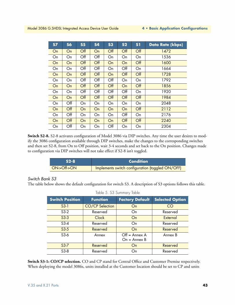
Model 3086 G.SHDSL Integrated Access Device User Guide 4 • Basic Application Configurations
Switch S2-8. S2-8 activates configuration of Model 3086 via DIP switches. Any time the user desires to mod-ify the 3086 configuration available through DIP switches, make the changes to the corresponding switches and then set S2-8, from On to Off position, wait 3-4 seconds and set back to the On position. Changes made to configuration via DIP switches will not take effect if S2-8 isn’t toggled.
Switch Bank S3The table below shows the default configuration for switch S3. A description of S3 options follows this table.
Switch S3-1: CO/CP selection. CO and CP stand for Central Office and Customer Premise respectively. When deploying the model 3086s, units installed at the Customer location should be set to CP and units
On On Off On Off Off Off 1472On On Off Off On On On 1536On On Off Off On On Off 1600On On Off Off On Off On 1664On On Off Off On Off Off 1728On On Off Off Off On On 1792On On Off Off Off On Off 1856On On Off Off Off Off On 1920On On Off Off Off Off Off 1984On Off On On On On On 2048On Off On On On On Off 2112On Off On On On Off On 2176On Off On On On Off Off 2240On Off On On Off On On 2304
S2-8 Condition
ON->Off->ON Implements switch configuration (toggled ON/OFF)
Table 5. S3 Summary Table
Switch Position Function Factory Default Selected Option
S3-1 CO/CP Selection On COS3-2 Reserved On ReservedS3-3 Clock On External S3-4 Reserved On ReservedS3-5 Reserved On ReservedS3-6 Annex Off = Annex A
On = Annex BAnnex B
S3-7 Reserved On ReservedS3-8 Reserved On Reserved
S7 S6 S5 S4 S3 S2 S1 Data Rate (kbps)
V.35 and X.21 Ports 43

4 • Basic Application Configurations Model 3086 G.SHDSL Integrated Access Device User Guide
installed at a Central Office should be set to CO. For point-to-point operation, one unit must be CO while the other must be CP.
Switch S3-3: Transmit Clock Mode. Use Switches S3-3 to configure the Model 3086 for internal or external clock mode (keep in mind that this setting only affects the operation of the serial port).
T1 InterfaceThe 3086 enables T1 or E1 device located at customer locations to access a carrier’s network over two wire, long reach DSL links. This capability allows providers to offer T1/E1 services at customer locations that were previously outside the reach of standard T1/E1 lines.
The 3086/K offers a user configurable T1 or E1 interface. Selection of the interface is done via DIP switches, HTTP/SNMP, or command line interface (CLI).
The T1 interface is an eight position keyed modular jack configured as a RJ-48C for connection to 100-ohm twisted pair lines.
Figure 10. 3086 T1 port pinout
T1 Interface ConnectionThe 3086 will usually connect either to a local T1 device, or to a Telco terminated T1 line jack.
• To connect the 3086’s T1 port to a local T1 device ( PBX, router, mux) use a T1 ‘crossover’ twisted pair cable. A crossover cable connects the transmit pins of the Model 3086’s T1 port to the receive pins of the device attached to this port and vice versa. Check the third party T1 equipment documentation for pinout information and cable requirements.
• To connect the 3086’s T1 port to a Telco terminated T1 line jack, use a straight through twisted pair patch cable. Consult with your T1 service provider for exact pinout information and cable requirements.
S3-3 Setting
Off CPON CO
S3-3 Clock mode
Off Internal. Transmit Clock to DTE is generated internally by the Model 3086 On External. Transmist Clock to DTE is generated from external clock signal received
from DTE. (This option is only available when the Model 3086 is set to CO mode.
44 T1 Interface

Model 3086 G.SHDSL Integrated Access Device User Guide 4 • Basic Application Configurations
T1 Interface ConfigurationThe 3086 T1 interface can be configured via DIP switches, HTTP/SNMP, or command line interface (CLI). This section discusses DIP switches and HTTP (web server) configuration. For CLI, see Appendix D, “Com-mand Line Interface (CLI) Operation” on page 163.
DIP Switch ConfigurationSwitch configuration in the 3086 is to be used in situations where the 3086 functions as a DSL modem carry-ing TDM (T1) data only without resorting to the use of a PC for configuration.
Note The Model 3086 is shipped with all DIP switches set to the ON posi-tion. While in this setting, the Model 3086 can be configured only via software (console, Telnet, HTTP, SNMP). If you want to use the DIP switches to configure the Model 3086, see section “Switch S2-8” on page 43 to activate the DIP switch configuration option.
The Model 3086 includes two eight-DIP switch banks labeled S2 and S3. They are externally accessible by removing the plate on the bottom side of the unit.
Switch Bank S2Table 6 shows the default configuration for switch S2. A description of S2 options follows the table.
Table 6. S2 Summary Table
Switch Position Function Factory Default Selected Option
S2-1 Data Rate On Not a valid rateS2-2 OnS2-3 OnS2-4 OnS2-5 OnS2-6 OnS2-7 OnS2-8 Switch configuration On Toggle On->Off>On
To activate DIP configuration
T1 Interface 45

4 • Basic Application Configurations Model 3086 G.SHDSL Integrated Access Device User Guide
Switches S2-1 through S2-7. Use Switches S2-1 through S2-7 to set the data rate (see Table 5 on page 43. Each position represents nx64 settings.
Switch S2-8. S2-8 activates configuration of Model 3086 via DIP switches. Any time the user desires to mod-ify the 3086 configuration available through DIP switches, make the changes to the corresponding switches and then set S2-8, from On to Off position, wait 3-4 seconds and set back to the On position. Changes made to configuration via DIP switches will not take effect if S2-8 isn’t toggled.
S7 S6 S5 S4 S3 S2 S1 Data Rate (kbps)
On On On On On On Off 64On On On On On Off On 128On On On On On Off Off 192On On On On Off On On 256On On On On Off On Off 320On On On On Off Off On 384On On On On Off Off Off 448On On On Off On On On 512On On On Off On On Off 576On On On Off On Off On 640On On On Off On Off Off 704On On On Off Off On On 768On On On Off Off On Off 832On On On Off Off Off On 896On On On Off Off Off Off 960On On Off On On On On 1024On On Off On On On Off 1088On On Off On On Off On 1152On On Off On On Off Off 1216On On Off On Off On On 1280On On Off On Off On Off 1344On On Off On Off Off On 1408On On Off On Off Off Off 1472On On Off Off On On On 1536
S2-8 Condition
ON->Off->ON Implements switch configuration (toggled ON/OFF)
46 T1 Interface

Model 3086 G.SHDSL Integrated Access Device User Guide 4 • Basic Application Configurations
Switch Bank S3The table below shows the default configuration for switch S3. A description of S3 options follows this table.
Switch S3-1: CO/CP selection. CO and CP stand for Central Office and Customer Premise respectively. When deploying the model 3086s, units installed at the Customer location should be set to CP and units installed at a Central Office should be set to CO. For point-to-point operation, one unit must be CO while the other must be CP.
Switch S3-3: Transmit Clock Mode. Use Switches S3-3 to configure the 3086 for internal or external (net-work) clock mode.
Table 7. S3 Summary Table
Switch Position Function Factory Default Selected Option
S3-1 CO/CP Selection On COS3-2 Reserved On ReservedS3-3 Clock On Network S3-4 Reserved On ReservedS3-5 Reserved On ReservedS3-6 Annex Off = Annex A
On = Annex BAnnex B
S3-7 Reserved On ReservedS3-8 Reserved On Reserved
S3-3 Setting
Off CPON CO
S3-3 Clock mode
Off Internal. DSL and T1 transmit clock generated by the 3086On External. DSL and T1 transmit clock derived from the received T1 signal (CO con-
figuration only)
T1 Interface 47
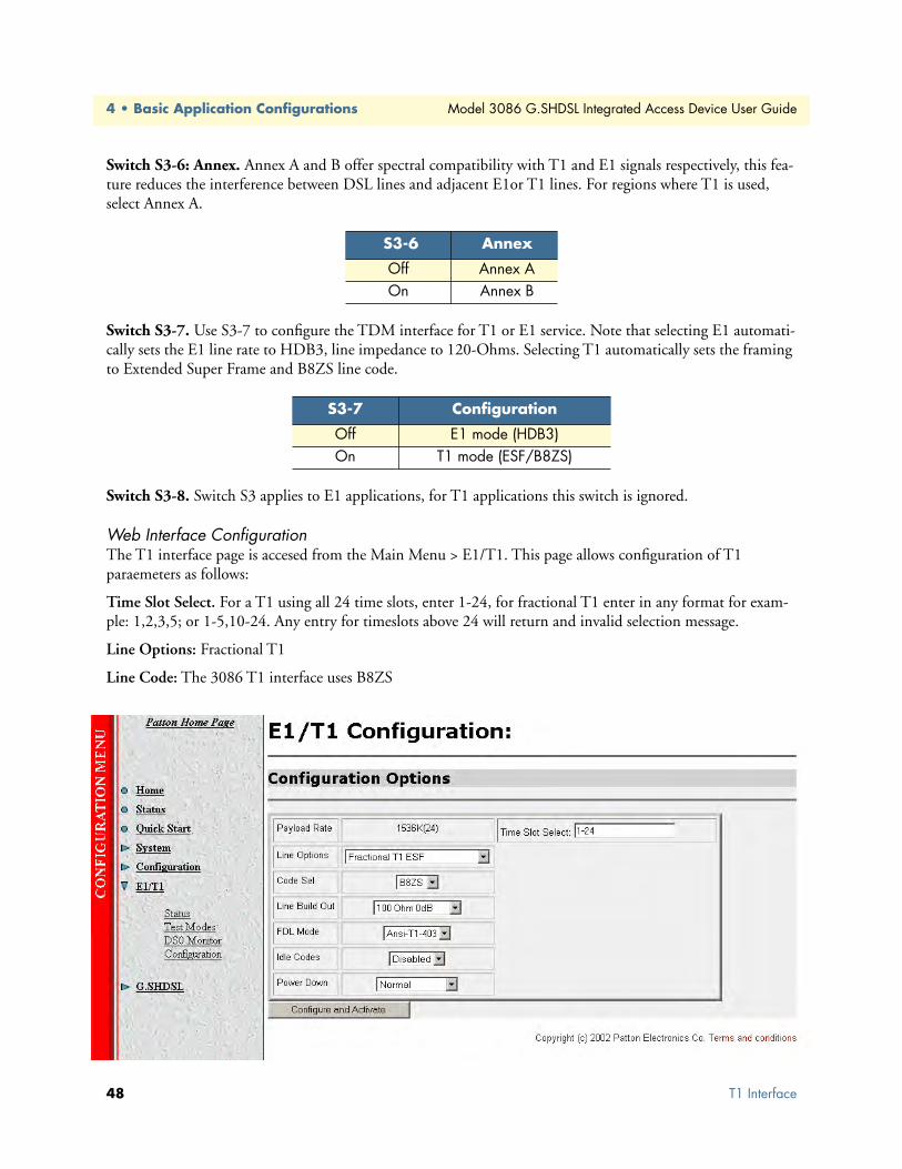
4 • Basic Application Configurations Model 3086 G.SHDSL Integrated Access Device User Guide
Switch S3-6: Annex. Annex A and B offer spectral compatibility with T1 and E1 signals respectively, this fea-ture reduces the interference between DSL lines and adjacent E1or T1 lines. For regions where T1 is used, select Annex A.
Switch S3-7. Use S3-7 to configure the TDM interface for T1 or E1 service. Note that selecting E1 automati-cally sets the E1 line rate to HDB3, line impedance to 120-Ohms. Selecting T1 automatically sets the framing to Extended Super Frame and B8ZS line code.
Switch S3-8. Switch S3 applies to E1 applications, for T1 applications this switch is ignored.
Web Interface ConfigurationThe T1 interface page is accesed from the Main Menu > E1/T1. This page allows configuration of T1 paraemeters as follows:
Time Slot Select. For a T1 using all 24 time slots, enter 1-24, for fractional T1 enter in any format for exam-ple: 1,2,3,5; or 1-5,10-24. Any entry for timeslots above 24 will return and invalid selection message.
Line Options: Fractional T1
Line Code: The 3086 T1 interface uses B8ZS
S3-6 Annex
Off Annex A On Annex B
S3-7 Configuration
Off E1 mode (HDB3)On T1 mode (ESF/B8ZS)
48 T1 Interface

Model 3086 G.SHDSL Integrated Access Device User Guide 4 • Basic Application Configurations
Line Build Out: Select from 100 ohm (0dB), 100 ohm (-7.5dB), 100 ohm (-15dB), and 100 ohm (-22.5dB). For CSU/DSU application use 100 0dB option, consult your T1 service provider for more information.
FDL Mode: Options are ANSI-T1-403, ATT-54016, and Fdl-none. Consult your T1 service provider or third party equipment for FDL mode required.
Idle code: Enabled, Disabled. When enabled, the 2603 inserts idle codes on unused timeslots. Set this option to ‘Disabled’ unless instructed otherwise.
Power Down: Normal, Powered Down. When powered down, T1/E1 transceiver input and output lines will be set to high impedance to protect the device—set unit to “Normal” for regular operation.
Once all options have been selected, click on the Configure and Activate at the bottom of the screen. Addition-ally, save the configuration by going to the Configuration > Save Config menu.
E1 InterfaceThe 3086 enables T1 or E1 device located at customer locations to access a carrier’s network over two wire, long reach DSL links. This capability allows providers to offer T1/E1 services at customer locations that were previously outside the reach of standard T1/E1 lines.
The 3086 offers a user configurable T1 or E1 interface. Selection of the interface is done via DIP switches, HTTP/SNMP, or command line interface (CLI).
The E1 interface is presented on both a modular, 8-pin RJ-48C jack for connection to 120-ohm twisted pair lines, and dual BNC female connectors for connection to 75-ohm coaxial lines.
Figure 11. E1 interface with RJ-48C jack (120–ohm) and dual BNC (75-ohm) connectors
E1 Interface Connection The 3086 will usually connect either to a local E1 device, or to a Telco terminated E1 line jack.
• To connect to the 3086 E1 port and a local E1 device (PBX, router, mux) use a E1 ‘crossover’ twisted pair cable. A crossover cable connects the transmit pins of the Model 3086’s E1 port to the receive pins of the device attached to this port and vice versa. Check the third party E1 equipment documentation for pinout
E1 Interface 49

4 • Basic Application Configurations Model 3086 G.SHDSL Integrated Access Device User Guide
information and cable requirements. If the E1 connection is made via the BNC connectors, connect the TX BNC of the 3086 to Recive (RX) BNC of the local E1 device, and vice versa.
• To connect the 3086’s E1 port to a Telco terminated E1 line jack, use a straight through twisted pair patch cable. Consult with your E1 service provider for exact pinout information and cable requirements.
The 3086 T1/E1 port can be configured via DIP switches, HTTP/SNMP, or command line interface (CLI). This section discusses DIP switches and HTTP (web server) configuration, for CLI and SNMP information see Appendix E on page 163.
DIP Switch ConfigurationSwitch configuration in the 3086 is to be used in situations where the 3086 functions as a DSL modem carry-ing TDM (E1) data only without resorting to the use of a PC for configuration.
Note The Model 3086 is shipped with all DIP switches set to the ON posi-tion. While in this setting, the Model 3086 can be configured only via software (console, Telnet, HTTP, SNMP). If you want to use the DIP switches to configure the Model 3086, see section “Switch S2-8” on page 43 to activate the DIP switch configuration option.
The Model 3086 includes two eight-DIP switch banks labeled S2 and S3. They are externally accessible by removing the plate on the bottom side of the unit.
Switch Bank S2A description of S2 options follows the table.
S7 S6 S5 S4 S3 S2 S1 Data Rate (kbps)
On On On On On On Off 64On On On On On Off On 128On On On On On Off Off 192On On On On Off On On 256On On On On Off On Off 320On On On On Off Off On 384On On On On Off Off Off 448On On On Off On On On 512On On On Off On On Off 576On On On Off On Off On 640On On On Off On Off Off 704On On On Off Off On On 768On On On Off Off On Off 832On On On Off Off Off On 896On On On Off Off Off Off 960On On Off On On On On 1024On On Off On On On Off 1088On On Off On On Off On 1152
50 E1 Interface

Model 3086 G.SHDSL Integrated Access Device User Guide 4 • Basic Application Configurations
Switch S2-8. S2-8 activates configuration of Model 3086 via DIP switches. Any time the user desires to mod-ify the 3086 configuration available through DIP switches, make the changes to the corresponding switches and then set S2-8, from On to Off position, wait 3-4 seconds and set back to the On position. Changes made to configuration via DIP switches will not take effect if S2-8 isn’t toggled.
Switch Bank S3The table below shows the default configuration for switch S3. A description of S3 options follows this table.
Switch S3-1: CO/CP selection. CO and CP stand for Central Office and Customer Premise respectively. When deploying the model 3086s, units installed at the Customer location should be set to CP and units
On On Off On On Off Off 1216On On Off On Off On On 1280On On Off On Off On Off 1344On On Off On Off Off On 1408On On Off On Off Off Off 1472On On Off Off On On On 1536On On Off Off On On Off 1600On On Off Off On Off On 1664On On Off Off On Off Off 1728On On Off Off Off On On 1792On On Off Off Off On Off 1856On On Off Off Off Off On 1920On On Off Off Off Off Off 1984On Off On On On On On 2048
S2-8 Condition
ON->Off->ON Implements switch configuration (toggled ON/OFF)
Table 8. S3 Summary Table
Switch Position Function Factory Default Selected Option
S3-1 CO/CP Selection On COS3-2 Reserved On ReservedS3-3 Clock On External S3-4 Reserved On ReservedS3-5 Reserved On ReservedS3-6 Annex Off = Annex A
On = Annex BAnnex B
S3-7 T1/E1 On T1S3-8 E1/CRC On No CRC
S7 S6 S5 S4 S3 S2 S1 Data Rate (kbps)
E1 Interface 51

4 • Basic Application Configurations Model 3086 G.SHDSL Integrated Access Device User Guide
installed at a Central Office should be set to CO. For point-to-point operation, one unit must be CO while the other must be CP.
Switch S3-3: Transmit Clock Mode. Use Switches S3-3 to configure the 3086 for internal or external clock mode.
Switch S3-6: Annex. Annex A and B offer spectral compatibility with T1 and E1 signals respectively, this fea-ture reduces the interference between DSL lines and adjacent E1or T1 lines. For regions where E1 is used, select Annex B.
Switch S3-7. Use S3-7 to configure the TDM interface for T1 or E1 service. Note that selecting E1 automati-cally sets the E1 line rate to HDB3, line impedance to 120-ohms. Selecting T1 automatically sets the framing to Extended Super Frame and B8ZS line code.
Switch S3-8. Switch S3-8 applies to E1 applications only. This switch selects whether the E1 link will use CRC or not while in framed mode. In Clear Channel mode (unframed) this switch is ignored.
S3-3 Setting
Off CPON CO
S3-3 Clock mode
Off Internal. Transmit clock generated by the 3086On External (network). DSL and E1 transmit clock derived from the received E1 signal
(available in CO mode only)
S3-6 Annex
Off Annex A On Annex B
S3-7 Configuration
Off E1 mode (HDB3)On T1 mode (ESF/B8ZS)
S3-8 Setting
Off E1 with CRC ON E1 without CRC
52 E1 Interface

Model 3086 G.SHDSL Integrated Access Device User Guide 4 • Basic Application Configurations
Web Interface ConfigurationLaunch Internet Explorer or similar web browser, type the IP address of the 2603, enter username ‘superuser’ and password ‘superuser’. From the main page click on the E1/T1 option > Configuration. This page allows configuration of E1 parameters as follows:
Time Slot Select. For unframed E1 service (Clear Channel) enter time slots 0-31. For a full framed E1 enter 1-31, for partially filled E1 enter the range of timeslots using the format for example: 1,2,3,5; or 1-5,10-31. Any entry for timeslots above 31 will return and invalid selection message.
Line Options: Choose from Clear Channel E1, Fractional E1, Fractional E1, Multi-Frame(CAS) E1, Multi-Frame(CAS) E1 with CRC. Consult with your service provider which option is required.
Line Code: Choose from AMI or HDB3. Most E1 applications use HDB3
Line Build Out: Select 120 ohm if the E1 connection is made via the RJ-48C connector, select 75 Ohm if the E1 connection is made via the Dual BNC connectors.
FDL Mode: FDL is a T1 application, therefore select ‘Fdl- none’ for E1 applications.
Idle code: Options are Enabled or Disabled. When idle code is Enabled, the 3086/K inserts idle codes on E1unused timeslots. Set this option to ‘Disabled’ unless instructed otherwise.
Power Down: Options are Normal and Powerdown. When the 3086 is set to powered down, it will set the E1 interface pins to high impedance to protect the device – set unit to “Normal” for regular operation.
Once all options have been selected, click on the Configure and Activate button at the bottom of the screen. Additionally, save the configuration by going to the Configuration > Save Config menu.
E1 Interface 53

4 • Basic Application Configurations Model 3086 G.SHDSL Integrated Access Device User Guide
Using the 3086 as a simple modem (TDM data over DSL)Serial port connection only, Ethernet port not used to send data over DSL but can be used for management.
There are three ways to configure the 3086 for serial port operation only:
• Via DIP switches
• Via the console port (using the command line interface or CLI)
• Via the Ethernet port using Telnet, Web browser, or SNMP tools.
For point-to-point operation (two 3086s connected directly) at 2.048 Mbps, follow the next example:
DIP Switch Configuration
Set switch S2-8 from On to Off, wait 3 to 4 seconds set it back to On.
CLI configurationWhen using the console port, or Telnet session via Ethernet port, the user has access to the 3086 command line interface (CLI). The above configuration can be entered via the CLI as follows:
3086 A CLI configuration
Note Press the Enter key at the end of each command line.
→ gshdsl set terminal central
→ gshdsl set dslrateTS 32
→ gshdsl set interface hdlc
3086 A 3086 B
Switch Setting Condition Switch Setting Condition S2-1 On 2.048 Mbps S2-1 On 2.048 Mbps S2-2 Off S2-2 OffS2-3 On S2-3 OnS2-4 On S2-4 OnS2-5 On S2-5 OnS2-6 On S2-6 OnS2-7 On S2-7 OnS2-8 On S2-8 OnS3-1 On CO S3-1 Off CPS3-3 Off Int. clock S3-3 Off Int. ClockS3-6 On Annex B S3-6 On Annex B
54 Using the 3086 as a simple modem (TDM data over DSL)

Model 3086 G.SHDSL Integrated Access Device User Guide 4 • Basic Application Configurations
→ gshdsl set pcmmode Serial
→ gshdsl set ghsannex AnnexB
→ gshdsl set serialTS 32
→ system config save
Wait for 'configuration saved' message…
Saving configuration…
→
→ Configuration saved.
3086 B CLI configuration
Note Press the Enter key at the end of each command line.
→ gshdsl set terminal remote
→ gshdsl set dslrateTS 32
→ gshdsl set interface hdlc
→ gshdsl set pcmmode Serial
→ gshdsl set ghsannex AnnexB
→ gshdsl set serialTS 32
→ system config save
Wait for 'configuration saved' message…
Saving configuration…
→
→ Configuration saved.
Note When connecting to Patton Electronics Model 3096RC Central Office T-DACS, The model 3086 must be configured as CP (Remote). Check the 3096RC user manual for information on the configuration of the 3096RC.
Using the 3086 as a simple modem (TDM data over DSL) 55

4 • Basic Application Configurations Model 3086 G.SHDSL Integrated Access Device User Guide
Web browser configuration From the main menu in the 3086, select GSHDSL > Configuration. Enter the selections as shown in the screen below. For Terminal Type, select Central for 3086 A, and Remote for 3086 B. Then go to the bottom of the screen and click on the Configure button.
Circuit IDUser can enter up to 30 alphanumeric characters for circuit identification
Clear Error CountersSelecting “Clear” will reset the error counters displayed in the “Status” screen.
Intended DSL Data RateThis is the DSL line rate at which you wish to connect. In a point-to-point deployment, the unit designated as “Central” will impose the line rate on the unit designated as “Remote”. The model 3086 offers nx64 kbps speeds from 192 kbps to 4.6 Mbps.
Actual DSL RateThis field displays the DSL rate connection; it displays the payload rate plus 8kbps automatically assigned to a DSL management channel. For instance, if a DSL rate of 1984 kbps is selected in the “Intended DSL Data Rate” window, the actual DSL data rate field will display 1992 kbps, this corresponds to 1984 kbps payload plus 8 kbps management channel.
56 Using the 3086 as a simple modem (TDM data over DSL)
Model 3086 G.SHDSL Integrated Access Device User Guide 4 • Basic Application Configurations
Intended Serial Interface Data RateSelects the data rate assigned to the serial port in nx64 kbps increments from 64 kbps to a maximum of 2.3 Mbps. The following conditions apply when configuring the 3086 serial port:
• When the 3086 is operating as a simple modem – serial port operation only, the data rate assigned to the serial port must match the DSL rate (except when selecting 64 or 128kbps, DSL line rate at these speeds is 192kbps).
• When the 3086 transports serial and Ethernet traffic simultaneously, total data rate assigned to both Serial and Ethernet must match the DSL rate.
• When using the 3086 for simultaneous Serial and Ethernet data transport, assign partial bandwidth to the serial port only, the 3086 will automatically assign the remaining DSL bandwidth to the Ethernet port.
• When using the 3086 for simultaneous Serial and Ethernet data transport, timeslots (64kbps slots) carrying serial data are placed in the upper slots of the DSL frame, while Ethernet data is placed in the lower DSL frame timeslots.
• When the serial port is not used, set the “Intended Serial Interface” to “Not used”. The 3086 will automat-ically assign all DSL bandwidth to the Ethernet port.
• When using a 3086 with T1/E1 interface, the “Intended Serial Interface” field must match the speed selected for the T1/E1 port in the T1/E1 configuration menu.
DSL Rate: Number of i BitThe i bit increments DSL speed by 8kbps in addition to the DSL rate selected in the “Intended DSL Data Rate” window. Most applications use nx64kbps DSL speeds, leave this setting at “0”, unless your application calls for a non-nx 64 speed. Selections for the I bit are 0 through 7 as follows:
• 0—No increment
• 1—Intended DSL data rate + 8 kbps
• 2—Intended DSL data rate + 16 kbps
• 3—Intended DSL data rate + 24 kbps
• 4—Intended DSL data rate + 32 kbps
• 5—Intended DSL data rate + 40 kbps
• 6—Intended DSL data rate + 48 kbps
• 7—Intended DSL data rate + 56 kbps
Terminal TypeSelect between Remote and Central. Use the “Remote” setting for 3086s located at customer premises. Use “Central” setting for units located at a Central Office or ISP.
Note The unit set to “Central” will act as master and will impose DSL rate on the unit set as “Remote”
Using the 3086 as a simple modem (TDM data over DSL) 57

4 • Basic Application Configurations Model 3086 G.SHDSL Integrated Access Device User Guide
Interface TypeSelects between HDLC or ATM transports. This setting must match the transport selected in the “WAN con-nection” menu. When using the 3086 to transport serial data only, select HDLC transport.
PCM ModeThe PCM mode selection tells the Model 3086 whether the DSL link will carry Serial data (from serial port), Ethernet data (from Ethernet port), or both Serial and Ethernet. Make sure to assign bandwidth to the serial port in the “Intended Serial Interface Data Rate” when selecting “Serial” or “Serial and Ethernet” traffic.
Clocking OptionsWhen using the serial port, the 3086 can transmit to the attached DTE using its internal clock, or using exter-nal clock from the DTE (this option is only available to units set for “Central”). Most applications use internal clock.
PCM Transmit PolarityWhen using long cables on the serial port side, it is possible that the clock and data arriving at the DTE may be out of synchronization, causing data errors. Inverting the polarity of the transmit clock at the 3086 may solve this problem. Use the “Normal” setting when using short serial cables (less than 6 feet or 1.8 meters).
PCM Receive PolarityWhen using long cables on the serial port side, it is possible that the clock and data arriving at the 3086 may be out of synchronization, causing data errors. Inverting the polarity of the receive clock at the 3086 may solve this problem. Use the “Normal” setting when using short serial cables (less than 6 feet or 1.8 meters).
LoopbackThe 3086 uses a series of loopbacks to test the serial, Ethernet, and DSL links, Refer to Chapter 9, “Diagnos-tics” on page 135 for more information.
Annex TypeAnnex type refers to spectral compatibility between DSL and T1 or E1 signals. For North America and other areas where T1 lines are used, select Annex A, for areas where E1 lines are used select Annex B.
Line ProbeLine probe is a tool used to determine maximum achievable rate when initially connecting 3086s to a copper line of unknown quality. Set this feature to “Enable” on both 3086s at each end of the link. Once line probe measurements have been completed set this feature to “Disabled”
Once you have completed your selections or changes, click on the Configure button at the bottom of the screen. Additionally, go to the G.SHDSL > Action link on the left side of the screen, and click action to start the DSL interface with the new settings.
TDM Plus Ethernet TrafficThe Model 3086 IAD can concurrently carry TDM data from the serial port (non-routed) and data from the Ethernet port, both data streams are carried simultaneously over the DSL link.
Note Data from the TDM port does not go through the routing core of the model 3086, this data is sent unprocessed over the DSL link.
58 TDM Plus Ethernet Traffic

Model 3086 G.SHDSL Integrated Access Device User Guide 4 • Basic Application Configurations
CLI configurationConfiguring the 3086 to transport TDM and IP data concurrently requires use of a Laptop or PC terminal. When carrying IP data, the Model 3086 offers two WAN encapsulation methods: HDLC and ATM. In addi-tion, when connecting two LAN segments over DSL, the 3086 offers options for Routed or Bridged services. The following example shows the configuration for connecting two LAN segments via DSL:
Selecting the DSL link speedIn this example a maximum DSL speed of 2.3Mbps (36 timeslots of 64 kbps each) will be selected, Using the CLI enter the following command:
→ gshdsl set dslrateTS 36 <enter>
Selecting PCM mode The PCM mode selection tells the Model 3086 Whether the DSL link will carry TDM data (from TDM port), Ethernet data (from Ethernet port), or both Serial and Ethernet.
In this example we will set the PCM mode for Serial and Ethernet data.
At the command prompt type:
→ gshdsl set pcmmode EthernetandSerial <enter>
Assigning bandwidth to serial and Ethernet ports In this example, half of the bandwidth 1.152 Mbps (18 TS) assigned to the serial port and the other half 1.152 Mbps (18 TS) assigned to the Ethernet port.
From the CLI command prompt type:
→ gshdsl set serialTS 18 <enter>
Note Enter the required bandwidth in number of 64kbps time slots for the serial port, the 3086 automatically assigns the rest of the bandwidth to the Ethernet ports. For example, if the total DSL bandwidth is 2.3 Mbps (36 TS), assigning 1.152 Mbps (18 TS) to the TDM port, automatically assigns the rest of the DSL bandwidth (18 TS) for Ethernet traffic.
When the 3086 carries both TDM and Ethernet traffic, it places serial data in the upper timeslots of the DSL frame, and Ethernet timeslots to the lower portion of the DSL frame. In the example above, Ethernet data (18 TS) occupies timeslots from 1–18, while TDM data (18 TS) is carried in TS 19–36 of the DSL frame.
Central or Remote terminal (Master/Slave)In a point-to-point deployment, one the two 3086s IAD must be set to Central (master), and the other to Remote (slave).
TDM Plus Ethernet Traffic 59

4 • Basic Application Configurations Model 3086 G.SHDSL Integrated Access Device User Guide
• For 3086 A at the prompt type
gshdsl set terminal central <enter>
• For 3086 B type
→ gshdsl set terminal remote
Interface TypeSelects between HDLC and ATM transport. To select HDLC for both 3086 type:
→ gshdsl set interface hdlc <enter>
Annex Type Select between Annex A and Annex B.
To select Annex B type:
→ gshdsl set ghsannex AnnexB
Web Browser Configuration The web browser offers the easiest way to configure the 3086. Log on the 3086 web server (default username: superuser, default password: superuser). From the main menu, click on the G.SHDSL option, select the “Con-
60 TDM Plus Ethernet Traffic

Model 3086 G.SHDSL Integrated Access Device User Guide 4 • Basic Application Configurations
figuration option”. Use the drop down menus to enter the required configuration. Once all settings have been selected, click on the Configure button at the bottom of the screen.
Circuit IDUser can enter up to 30 alphanumeric characters for circuit identification
Clear Error CountersSelecting “Clear” will reset the error counters displayed in the “Status” screen.
Intended DSL Data RateThis is the DSL line rate at which you wish to connect. In a point-to-point deployment, the unit designated as “Central” will impose the line rate on the unit designated as “Remote”. The model 3086 offers nx64 kbps speeds from 192 kbps to 4.6 Mbps.
Actual DSL RateThis field displays the DSL rate connection; it displays the payload rate plus 8kbps automatically assigned to a DSL management channel. For instance, if a DSL rate of 1984 kbps is selected in the “Intended DSL Data Rate” window, the actual DSL data rate field will display 1992 kbps, this corresponds to 1984 kbps payload plus 8 kbps management channel.
TDM Plus Ethernet Traffic 61
4 • Basic Application Configurations Model 3086 G.SHDSL Integrated Access Device User Guide
Intended Serial Interface Data RateSelects the data rate assigned to the serial port in nx64 kbps increments from 64 kbps to a maximum of 2.3 Mbps. The following conditions apply when configuring the 3086 serial port:
• When the 3086 is operating as a simple modem – serial port operation only, the data rate assigned to the serial port must match the DSL rate (except when selecting 64 or 128kbps, DSL line rate at these speeds is 192kbps).
• When the 3086 transports serial and Ethernet traffic simultaneously, total data rate assigned to both Serial and Ethernet must match the DSL rate.
• When using the 3086 for simultaneous Serial and Ethernet data transport, assign partial bandwidth to the serial port only, the 3086 will automatically assign the remaining DSL bandwidth to the Ethernet port.
• When using the 3086 for simultaneous Serial and Ethernet data transport, timeslots (64kbps slots) carrying serial data are placed in the upper slots of the DSL frame, while Ethernet data is placed in the lower DSL frame timeslots.
• When the serial port is not used, set the “Intended Serial Interface” to “Not used”. The 3086 will automat-ically assign all DSL bandwidth to the Ethernet port.
• When using a 3086 with T1/E1 interface, the “Intended Serial Interface” field must match the speed selected for the T1/E1 port in the T1/E1 configuration menu.
DSL Rate: Number of i BitThe i bit increments DSL speed by 8kbps in addition to the DSL rate selected in the “Intended DSL Data Rate” window. Most applications use nx64kbps DSL speeds, leave this setting at “0”, unless your application calls for a non-nx 64 speed. Selections for the I bit are 0 through 7 as follows:
• 0—No increment
• 1—Intended DSL data rate + 8 kbps
• 2—Intended DSL data rate + 16 kbps
• 3—Intended DSL data rate + 24 kbps
• 4—Intended DSL data rate + 32 kbps
• 5—Intended DSL data rate + 40 kbps
• 6—Intended DSL data rate + 48 kbps
• 7—Intended DSL data rate + 56 kbps
Terminal TypeSelect between Remote and Central. Use the “Remote” setting for 3086s located at customer premises. Use “Central” setting for units located at a Central Office or ISP.
Note The unit set to “Central” will act as master and will impose DSL rate on the unit set as “Remote”
62 TDM Plus Ethernet Traffic

Model 3086 G.SHDSL Integrated Access Device User Guide 4 • Basic Application Configurations
Interface TypeSelects between HDLC or ATM transports. This setting must match the transport selected in the “WAN con-nection” menu. When using the 3086 to transport serial data only, select HDLC transport.
PCM ModeThe PCM mode selection tells the Model 3086 whether the DSL link will carry Serial data (from serial port), Ethernet data (from Ethernet port), or both Serial and Ethernet. Make sure to assign bandwidth to the serial port in the “Intended Serial Interface Data Rate” when selecting “Serial” or “Serial and Ethernet” traffic.
Clocking OptionsWhen using the serial port, the 3086 can transmit to the attached DTE using its internal clock, or using exter-nal clock from the DTE (this option is only available to units set for “Central”). Most applications use internal clock.
PCM Transmit PolarityWhen using long cables on the serial port side, it is possible that the clock and data arriving at the DTE may be out of synchronization, causing data errors. Inverting the polarity of the transmit clock at the 3086 may solve this problem. Use the “Normal” setting when using short serial cables (less than 6 feet or 1.8 meters).
PCM Receive PolarityWhen using long cables on the serial port side, it is possible that the clock and data arriving at the 3086 may be out of synchronization, causing data errors. Inverting the polarity of the receive clock at the 3086 may solve this problem. Use the “Normal” setting when using short serial cables (less than 6 feet or 1.8 meters).
LoopbackThe 3086 uses a series of loopbacks to test the serial, Ethernet, and DSL links, Refer to Chapter 9, “Diagnos-tics” on page 135 for more information.
Annex TypeAnnex type refers to spectral compatibility between DSL and T1 or E1 signals. For North America and other areas where T1 lines are used, select Annex A, for areas where E1 lines are used select Annex B.
Line ProbeLine probe is a tool used to determine maximum achievable rate when initially connecting 3086s to a copper line of unknown quality. Set this feature to “Enable” on both 3086s at each end of the link. Once line probe measurements have been completed set this feature to “Disabled”
Once you have completed your selections or changes, click on the Configure button at the bottom of the screen. Additionally, go to the G.SHDSL > Action link on the left side of the screen, and click action to start the DSL interface with the new settings.
This concludes the basic DSL configuration for Ethernet and serial ports.
If your application calls for Ethernet only, or Serial and Ethernet traffic you need to configure the Model 3086 Ethernet transport between HDLC or ATM encapsulation. In addition, select between bridged or routed con-figuration options, whichever meets your network needs. The following section steps through the various application configurations options possible with the 3086.
TDM Plus Ethernet Traffic 63

4 • Basic Application Configurations Model 3086 G.SHDSL Integrated Access Device User Guide
Using the 3086 in Routed or Bridged applications
Two stand-alone units directly connected
Ethernet extension (HDLC – PPPOH) Bridged
Model 3086 (Remote) Configuration Steps (PPPoH Bridged)
From the command line interface (CLI) via the RS-232 control port,
→ ip list interfaces
One IP interface is called ip1 with an IP address of 192.168.1.1
Let’s change the IP address so it is in the same subnet as both PCs. For example, to 192.168.100.2
→ ip set interface ip1 ipaddress 192.168.100.2 255.255.255.0
1. Now you can bring up the web-page management system on your browser by entering the IP address of the 3086.
2. On the Menu, go to Configuration, then to WAN Connections. Delete the factory default WAN services already defined.
Click on Create a new service in the main window, select PPPoH_Bridged and click on the Configure button.
3. In the Description field, enter the description you wish. In this example, it is called PPPoH Bridged.
64 Using the 3086 in Routed or Bridged applications

Model 3086 G.SHDSL Integrated Access Device User Guide 4 • Basic Application Configurations
Verify the settings to be:
– Interface = 1
– LLC header mode = dialout
– LLC header mode = off
– HDLC header mode = on
– No authentication
– Leave User name and Password blank.
Click on Apply.
4. Go to G.SHDSL in the Configuration Menu, then the submenu Configuration.
Using the 3086 in Routed or Bridged applications 65

4 • Basic Application Configurations Model 3086 G.SHDSL Integrated Access Device User Guide
Change Terminal Type to Central and Interface Type to hdlc. Click on the Configure button.
In the Action submenu under G.SHDSL, change Action to Deactivate, then click on Action.
Return to Action, select Start and click on Action.
Model 3086 (Central) Configuration Steps (PPPoH Bridged)
See the Web page images for the Remote Model 3086 configuration above.
From the command line interface (CLI) via the RS-232 control port,
→ ip list interfaces
One IP interface is called ip1 with an IP address of 192.168.1.1
Change the IP address so it is in the same subnet as both PCs. For example, to 192.168.100.3
→ ip set interface ip1 ipaddress 192.168.100.3 255.255.255.0
1. Now you can bring up the web-page management system on your browser by entering the IP address of the 3086.
2. On the Menu, go to Configuration, then to WAN Connections. Delete the factory default WAN services already defined.
Click on Create a new service in the main window, select PPPoH_Bridged and click on the Configure button.
In the Description field, enter the description you wish. In this example, it is called PPPoH Bridged.
Verify the settings to be:
– Interface = 1
– LLC header mode = dialout
66 Using the 3086 in Routed or Bridged applications

Model 3086 G.SHDSL Integrated Access Device User Guide 4 • Basic Application Configurations
– LLC header mode = off
– HDLC header mode = on
– No authentication
– Leave User name and Password blank.
Click on Apply.
3. Go to G.SHDSL in the Configuration Menu, then the submenu Configuration.
Leave Terminal Type as Remote.
Change Interface Type to hdlc. Click on the Configure button.
In the Action submenu under G.SHDSL, change Action to Deactivate, then click on Action.
Return to Action, select Start and click on Action.
Network Extension (HDLC—PPPoH Routed)
Model 3086 (Remote) Configuration Steps (PPPoH Routed)
From the command line interface (CLI) via the RS-232 control port,
→ ip list interfaces
One IP interface was called ip1 with an IP address of 192.168.1.1 Change it to an IP address which is in the same subnet as the Desktop PC. For example, to 192.168.100.2. The default IP mask is 255.255.255.0.
→ ip set interface ip1 ipaddress 192.168.100.2 255.255.255.0
Using the 3086 in Routed or Bridged applications 67

4 • Basic Application Configurations Model 3086 G.SHDSL Integrated Access Device User Guide
1. Now you can bring up the web-page management system on your browser by entering the IP address of the 3086.
Click on G.SHDSL in the Configuration Menu > Configuration > verify that Terminal Type is Central and Interface Type is “hdlc.” If changed, then click on Configure.
Click on Action > Select deactivate for Action > Click on the Action button.
2. On the Menu, go to Configuration, then to WAN Connections
Delete both default WAN services already defined.
Click on Create a new service in the main window, select PPPoH_Routed and click on the Configure button.
In the Description field, enter the description you wish. In this example, it is called PPPoH Routed.
– Description: PPPoH Routed
– Interface: 1
– WAN IP address: 192.168.164.2
– LLC Header Mode: off
– HDLC Header Mode: ON
– No authentication
– Username: [blank]
– Password: [blank]
68 Using the 3086 in Routed or Bridged applications

Model 3086 G.SHDSL Integrated Access Device User Guide 4 • Basic Application Configurations
Click on Configure.
3. Go to Configuration Menu > Configuration > WAN connections > Edit (for PPPoH Routed service) > Edit ‘IP Interface’ > Ipaddr: [enter the WAN IP Address, in this example = 192.168.164.2] > Click on Change.
Using the 3086 in Routed or Bridged applications 69

4 • Basic Application Configurations Model 3086 G.SHDSL Integrated Access Device User Guide
4. Configuration Menu > Configuration > IP Routes > Click on Create new Ip V4 Route > Create the gateway to the remote 3086 by entering the WAN IP address of the remote 3086, in this example, enter 192.168.164.3 in the Gateway field > OK
The other fields should be:
– Destination: 0.0.0.0
– Gateway: 192.168.164.3 [already configured in first part of step 4).]
– Mask: 0.0.0.0
– Cost: 1
– Interface: [blank]
70 Using the 3086 in Routed or Bridged applications

Model 3086 G.SHDSL Integrated Access Device User Guide 4 • Basic Application Configurations
5. Go to G.SHDSL in the Configuration Menu, then the submenu Status. The Modem State should be “deactivated.” (If not, go to the Action and change it to deactivate.)
Then in the Action submenu under G.SHDSL, change Action to Start, then click on Action.
Model 3086 (Central) Configuration Steps (PPPoH Routed)
See the web pages for the desktop above. Some parametric values are different although the process is the same.
From the command line interface (CLI) via the RS-232 control port,
→ ip list interfaces
→ ip clear routes
→ pppoh clear transports
→ ethernet add transport eth1 ethernet
One IP interface was called ip1 with an IP address of 192.168.1.1
Change the IP address so it is in the same subnet as the laptop PC. The laptop’s IP address is 192.168.172.229, so in this example, change the IP address of the 3086 to 192.168.172.3. The default IP mask is 255.255.255.0.
→ ip set interface ip1 ipaddress 192.168.172.3 255.255.255.0
1. Now you can bring up the web-page management system on your browser by entering the IP address of the 3086.
Using the 3086 in Routed or Bridged applications 71

4 • Basic Application Configurations Model 3086 G.SHDSL Integrated Access Device User Guide
Click on G.SHDSL in the Configuration Menu > Configuration > verify that Terminal Type is remote and Interface Type is “hdlc.” If changed, then click on Configure.
Click on Action > Select deactivate for Action > Click on the Action button.
2. On the Menu, go to Configuration, then to WAN Connections.
Delete both default WAN services already defined.
Click on Create a new service in the main window, select PPPoH_Routed and click on the Configure button.
In the Description field, enter the description you wish. In this example, it is called PPPoH Routed.
Description:PPPoH Routed
– Interface:1
– WAN IP address: 192.168.164.3
– LLC Header Mode:off
– HDLC Header Mode:ON
– No authentication
– Username:[blank]
– Password:[blank]
Click on Configure.
3. Go to Configuration Menu > Configuration > WAN connections > Edit (for PPPoH Routed service) > Edit ‘IP Interface’ > Ipaddr: [enter the WAN IP Address, in this example = 192.168.164.3] > Click on Change.
4. Configuration Menu > Configuration > IP Routes > Click on Create new Ip V4 Route > Create the gateway to the remote 3086 by entering the WAN IP address of the remote 3086, in this example, enter 192.168.164.2 in the Gateway field > OK
The other fields should be:
– Destination:0.0.0.0
– Gateway:192.168.164.2 [already changed in the first part of step 5).]
– Mask:0.0.0.0
72 Using the 3086 in Routed or Bridged applications

Model 3086 G.SHDSL Integrated Access Device User Guide 4 • Basic Application Configurations
– Cost:1
– Interface:[blank]
5. Go to G.SHDSL in the Configuration Menu, then the submenu Status. The Modem State should be “deacti-vated.” (If not, go to the Action and change it to deactivate.)
Then in the Action submenu under G.SHDSL, change Action to Start, then click on Action.
DSLAM Connections with remote CPE units
Bridged application configurations to a DSLAMThree bridged services are offered, RFC 1483 Bridged, PPPoA Bridged, and HDLC Bridged.
The configurations show a desktop on one end and a laptop on the other. The laptop and its Model 3086 would be replaced with a DSLAM.
RFC 1483 Bridged Configuration.No additional IP addresses are needed other than the IP address chosen earlier. In fact, if you are configuring and managing the model 3086 only from the CLI (Command Line Interface), an IP address is not needed at all. The limitation of no IP address precludes the user from doing web management of the 3086 since management is done via the Ethernet port.
As in the PPPoA Bridged application, both sides of the RFC 1483 bridged connection are on the same subnet.
DSLAM Connections with remote CPE units 73

4 • Basic Application Configurations Model 3086 G.SHDSL Integrated Access Device User Guide
Model 3086 (Remote) Configuration Steps (RFC 1483 Bridged)
From the command line interface (CLI) via the RS-232 control port,
→ ip list interfaces
One IP interface is called ip1 with an IP address of 192.168.1.1
Change the IP address so it is in the same subnet as both PCs. For example, to 192.168.100.2
→ ip set interface ip1 ipaddress 192.168.100.2 255.255.255.0
1. Now you can bring up the web-page management system on your browser by entering the IP address of the 3086.
2. On the Menu, go to Configuration, then to WAN Connections. Delete the factory default WAN services already defined.
Click on Create a new service in the main window, select RFC_1483_Bridged and click on the Configure button.
In the Description field, enter the description you wish. In this example, it is called RFC 1483 B.
Leave VCI as 35 and Encapsulation Method as LLC/SNAP. Then click on Apply.
3. Go to G.SHDSL in the Configuration Menu, then the submenu Configuration.
74 DSLAM Connections with remote CPE units

Model 3086 G.SHDSL Integrated Access Device User Guide 4 • Basic Application Configurations
Change Terminal Type to Remote and Interface Type to atm. Click on the Configure button.
In the Action submenu under G.SHDSL, change Action to Deactivate, then click on Action.
Return to Action, select Start and click on Action.
Model 3086 (Central) Configuration Steps (RFC 1483 Bridged)
Although the some parametric values may vary from the desktop’s Model 3086, the process is identical.
From the command line interface (CLI) via the RS-232 control port,
→ ip list interfaces
One IP interface is called ip1 with an IP address of 192.168.1.1
Change the IP address so it is in the same subnet as both PCs. For example, to 192.168.100.3
→ ip set interface ip1 ipaddress 192.168.100.3 255.255.255.0
1. Now you can bring up the web-page management system on your browser by entering the IP address of the 3086.
2. On the Menu, go to Configuration, then to WAN Connections. Delete the factory default WAN services already defined.
Click on Create a new service in the main window, select RFC_1483_Bridged and click on the Configure button.
In the Description field, enter the description you wish. In this example, it is called RFC 1483 B.
DSLAM Connections with remote CPE units 75

4 • Basic Application Configurations Model 3086 G.SHDSL Integrated Access Device User Guide
Leave VCI as 35 and Encapsulation Method as LLC/SNAP. Then click on Apply.
3. Go to G.SHDSL in the Configuration Menu, then the submenu Configuration.
Leave Terminal Type as Remote, but change Interface Type to atm. Click on the Configure button.
In the Action submenu under G.SHDSL, change Action to Deactivate, then click on Action.
Return to Action, select Start and click on Action.
PPPoH Bridged Configuration
Model 3086 (Remote) Configuration Steps (PPPoH Bridged)
From the command line interface (CLI) via the RS-232 control port,
→ ip list interfaces
One IP interface is called ip1 with an IP address of 192.168.1.1 Change the IP address so it is in the same sub-net as both PCs. For example, to 192.168.100.2
→ ip set interface ip1 ipaddress 192.168.100.2 255.255.255.0
1. Now you can bring up the web-page management system on your browser by entering the IP address of the 3086.
2. On the Menu, go to Configuration, then to WAN Connections. Delete the factory default WAN services already defined.
76 DSLAM Connections with remote CPE units

Model 3086 G.SHDSL Integrated Access Device User Guide 4 • Basic Application Configurations
Click on Create a new service in the main window, select PPPoH_Bridged and click on the Configure button.
In the Description field, enter the description you wish. In this example, it is called PPPoH Bridged.
– Interface = 1
– LLC header mode = dialout
– LLC header mode = off
– HDLC header mode = on
– No authenticaion
– Leave User name and Password blank.
– Click on Apply.
3. Go to G.SHDSL in the Configuration Menu, then the submenu Configuration.
– Change Terminal Type to Remote and Interface Type to hdlc. Click on the Configure button.
– In the Action submenu under G.SHDSL, change Action to Deactivate, then click on Action.
– Return to Action, select Start and click on Action.
DSLAM Connections with remote CPE units 77

4 • Basic Application Configurations Model 3086 G.SHDSL Integrated Access Device User Guide
Model 3086 (Central) Configuration Steps (PPPoH Bridged)
From the command line interface (CLI) via the RS-232 control port,
→ ip list interfaces
One IP interface is called ip1 with an IP address of 192.168.1.1
Change the IP address so it is in the same subnet as both PCs. For example, to 192.168.100.3
→ ip set interface ip1 ipaddress 192.168.100.3 255.255.255.0
1. Now you can bring up the web-page management system on your browser by entering the IP address of the 3086.
2. On the Menu, go to Configuration, then to WAN Connections. Delete the factory default WAN services already defined.
Click on Create a new service in the main window, select PPPoH_Bridged and click on the Configure button.
In the Description field, enter the description you wish. In this example, it is called PPPoH Bridged.
– Interface = 1
– LLC header mode = dialout
– LLC header mode = off
– HDLC header mode = on
– No authenticaion
– Leave User name and Password blank.
Click on Apply.
3. Go to G.SHDSL in the Configuration Menu, then the submenu Configuration.
Leave Terminal Type as Central.
Change Interface Type to hdlc. Click on the Configure button.
In the Action submenu under G.SHDSL, change Action to Deactivate, then click on Action.
Return to Action, select Start and click on Action.
78 DSLAM Connections with remote CPE units

Model 3086 G.SHDSL Integrated Access Device User Guide 4 • Basic Application Configurations
PPPoA Bridged (RFC 2364) ConfigurationThe user data for transmission is in the form of IP packets but encapsulated in a PPP packet, transmitted and received through a PPP session to the connection. The PPP packets are encapsulated according to RFC 2364 for transmission over the ATM link. The packets are de-encapsulated on the receive side so that the IP data can be delivered to the end user.
Model 3086 (Remote) Configuration Steps (PPPoA Bridged)
From the command line interface (CLI) via the RS-232 control port,
→ ip list interfaces
One IP interface is called ip1 with an IP address of 192.168.1.1
Change the IP address so it is in the same subnet as both PCs. For example, to 192.168.100.2
→ ip set interface ip1 ipaddress 192.168.100.2 255.255.255.0
1. Now you can bring up the web-page management system on your browser by entering the IP address of the 3086.
2. On the Menu, go to Configuration, then to WAN Connections. Delete the factory default WAN services already defined.
Click on Create a new service in the main window, select PPPoA_Bridged and click on the Configure button.
In the Description field, enter the description you wish. In this example, it is called PPPoA Bridged.
DSLAM Connections with remote CPE units 79

4 • Basic Application Configurations Model 3086 G.SHDSL Integrated Access Device User Guide
– VPI = 0
– VCI = 300
– LLC header mode = off
– HDLC header mode = off
– No authentication
– Leave User name and Password blank.
Click on Apply.
3. Go to G.SHDSL in the Configuration Menu, then the submenu Configuration.
Change Terminal Type to Remote and Interface Type to atm. Click on the Configure button.
In the Action submenu under G.SHDSL, change Action to Deactivate, then click on Action.
Return to Action, select Start and click on Action.
Model 3086 (Central)Configuration Steps (PPPoA Bridged)
From the command line interface (CLI) via the RS-232 control port,
→ ip list interfaces
One IP interface is called ip1 with an IP address of 192.168.1.1
Change the IP address so it is in the same subnet as both PCs. For example, to 192.168.100.3
→ ip set interface ip1 ipaddress 192.168.100.3 255.255.255.0
1. Now you can bring up the web-page management system on your browser by entering the IP address of the 3086.
2. On the Menu, go to Configuration, then to WAN Connections. Delete the factory default WAN services already defined.
Click on Create a new service in the main window, select PPPoA_Bridged and click on the Configure button.
In the Description field, enter the description you wish. In this example, it is called PPPoA Bridged.
– VPI = 0
– VCI = 300
– LLC header mode = off
– HDLC header mode = off
80 DSLAM Connections with remote CPE units

Model 3086 G.SHDSL Integrated Access Device User Guide 4 • Basic Application Configurations
– No authentication
– Leave User name and Password blank.
Click on Apply.
3. Go to G.SHDSL in the Configuration Menu, then the submenu Configuration.
Leave Terminal Type as Central.
Change Interface Type to atm. Click on the Configure button.
In the Action submenu under G.SHDSL, change Action to Deactivate, then click on Action.
Return to Action, select Start and click on Action.
Routed application configurations to a DSLAMFive routed WAN services are offered, RFC 1483, PPPoH, IPoA, PPPoA, and PPPoE Routed.
RFC 1483 RoutedRFC 1483 provides the simplest method of connecting end stations over an ATM network. User data in the form of Ethernet packets is encapsulated into AAL-5 PDUs for transport over ATM. RFC 1483 provides no authentication and configuration that would be provided by PPP.
Model 3086 (Remote) Configuration Steps (RFC 1483 Routed)
From the command line interface (CLI) via the RS-232 control port,
→ ip list interfaces
One IP interface was called ip1 with an IP address of 192.168.1.1 Change it to an IP address which is in the same subnet as the Desktop PC. For example, to 192.168.100.2. The default IP mask is 255.255.255.0.
→ ip set interface ip1 ipaddress 192.168.100.2 255.255.255.0
DSLAM Connections with remote CPE units 81

4 • Basic Application Configurations Model 3086 G.SHDSL Integrated Access Device User Guide
1. Now you can bring up the web-page management system on your browser by entering the IP address of the 3086.
Click on G.SHDSL in the Configuration Menu > Configuration > verify that Terminal Type is Central and Interface Type is atm. If changed, then click on Configure.
Click on Action > Select deactivate for Action > Click on the Action button.
2. On the Menu, go to Configuration, then to WAN Connections.
Delete both default WAN services already defined.
Click on Create a new service in the main window, select RFC 1483 Routed and click on the Configure button.
82 DSLAM Connections with remote CPE units

Model 3086 G.SHDSL Integrated Access Device User Guide 4 • Basic Application Configurations
In the Description field, enter the description you wish. In this example, it is called RFC 1483 Routed. Change the configuration parameters to match the following.
Description:RFC 1483 Routed
– VPI:0
– VCI:35
– Encapsulation Method: LLC/SNAP
– WAN IP Address:192.168.164.2
Click on Configure.
3. Configuration Menu > Configuration > IP Routes > Click on Create new Ip V4 Route > Create the gate-way to the remote 3086 by entering the WAN IP address of the remote 3086, in this example, enter 192.168.164.3 in the Gateway field > OK
DSLAM Connections with remote CPE units 83

4 • Basic Application Configurations Model 3086 G.SHDSL Integrated Access Device User Guide
The other fields should be:
– Destination:0.0.0.0
– Gateway:192.168.164.3
– Mask:0.0.0.0
– Cost:1
– Interface:[blank]
4. Go to G.SHDSL in the Configuration Menu, then the submenu Status. The Modem State should be “deactivated.” (If not, go to the Action and change it to deactivate.)
Then in the Action submenu under G.SHDSL, change Action to Start, then click on Action.
Model 3086 (Central) Configuration Steps (RFC 1483 Routed)
From the command line interface (CLI) via the RS-232 control port,
→ ip list interfaces
→ pppoh clear transports
One IP interface was called ip1 with an IP address of 192.168.1.1
84 DSLAM Connections with remote CPE units

Model 3086 G.SHDSL Integrated Access Device User Guide 4 • Basic Application Configurations
Change the IP address so it is in the same subnet as the laptop PC. The laptop’s IP address is 192.168.172.229, so in this example, change the IP address of the 3086 to 192.168.172.3. The default IP mask is 255.255.255.0.
→ ip set interface ip1 ipaddress 192.168.100.2 255.255.255.0
1. Now you can bring up the web-page management system on your browser by entering the IP address of the 3086.
Click on G.SHDSL in the Configuration Menu > Configuration > verify that Terminal Type is Remote and Interface Type is atm. If changed, then click on Configure.
DSLAM Connections with remote CPE units 85
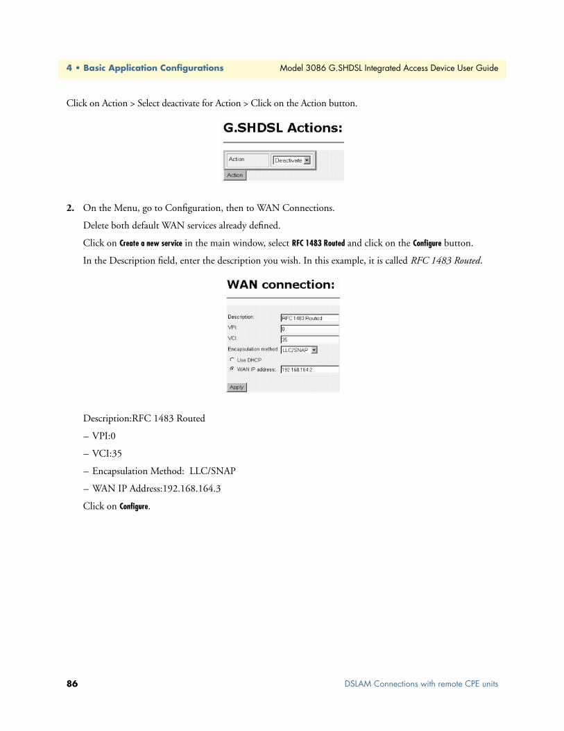
4 • Basic Application Configurations Model 3086 G.SHDSL Integrated Access Device User Guide
Click on Action > Select deactivate for Action > Click on the Action button.
2. On the Menu, go to Configuration, then to WAN Connections.
Delete both default WAN services already defined.
Click on Create a new service in the main window, select RFC 1483 Routed and click on the Configure button.
In the Description field, enter the description you wish. In this example, it is called RFC 1483 Routed.
Description:RFC 1483 Routed
– VPI:0
– VCI:35
– Encapsulation Method: LLC/SNAP
– WAN IP Address:192.168.164.3
Click on Configure.
86 DSLAM Connections with remote CPE units

Model 3086 G.SHDSL Integrated Access Device User Guide 4 • Basic Application Configurations
3. Configuration Menu > Configuration > IP Routes > Click on Create new Ip V4 Route > Create the gate-way to the remote 3086 by entering the WAN IP address of the remote 3086, in this example, enter 192.168.164.2 in the Gateway field > OK
The other fields should be:
– Destination:0.0.0.0
– Gateway:192.168.164.2
– Mask:0.0.0.0
– Cost:1
– Interface:[blank]
DSLAM Connections with remote CPE units 87

4 • Basic Application Configurations Model 3086 G.SHDSL Integrated Access Device User Guide
4. Go to G.SHDSL in the Configuration Menu, then the submenu Status. The Modem State should be “deactivated.” (If not, go to the Action and change it to deactivate.)
Then in the Action submenu under G.SHDSL, change Action to Start, then click on Action.
The modems should link up within 30 seconds or so and the link is ready for communication.
PPPoH Routed
Model 3086 (Remote) Configuration Steps (PPPoH Routed)
From the command line interface (CLI) via the RS-232 control port,
→ ip list interfaces
→ ip clear routes
→ pppoh clear transports
88 DSLAM Connections with remote CPE units

Model 3086 G.SHDSL Integrated Access Device User Guide 4 • Basic Application Configurations
One IP interface was called ip1 with an IP address of 192.168.1.1 Change it to an IP address which is in the same subnet as the Desktop PC. For example, to 192.168.100.2. The default IP mask is 255.255.255.0.
→ ip set interface ip1 ipaddress 192.168.100.2 255.255.255.0
1. Now you can bring up the web-page management system on your browser by entering the IP address of the 3086.
Click on G.SHDSL in the Configuration Menu > Configuration > verify that Terminal Type is Central and Interface Type is hdlc. If changed, then click on Configure.
Click on Action > Select deactivate for Action > Click on the Action button.
2. On the Menu, go to Configuration, then to WAN Connections
Delete both default WAN services already defined.
Click on Create a new service in the main window, select PPPoH_Routed and click on the Configure button.
In the Description field, enter the description you wish. In this example, it is called PPPoH Routed.
– Description:PPPoH Routed
– Interface:1
– WAN IP address: 192.168.164.2
– LLC Header Mode:off
– HDLC Header Mode:ON
– No authentication
DSLAM Connections with remote CPE units 89
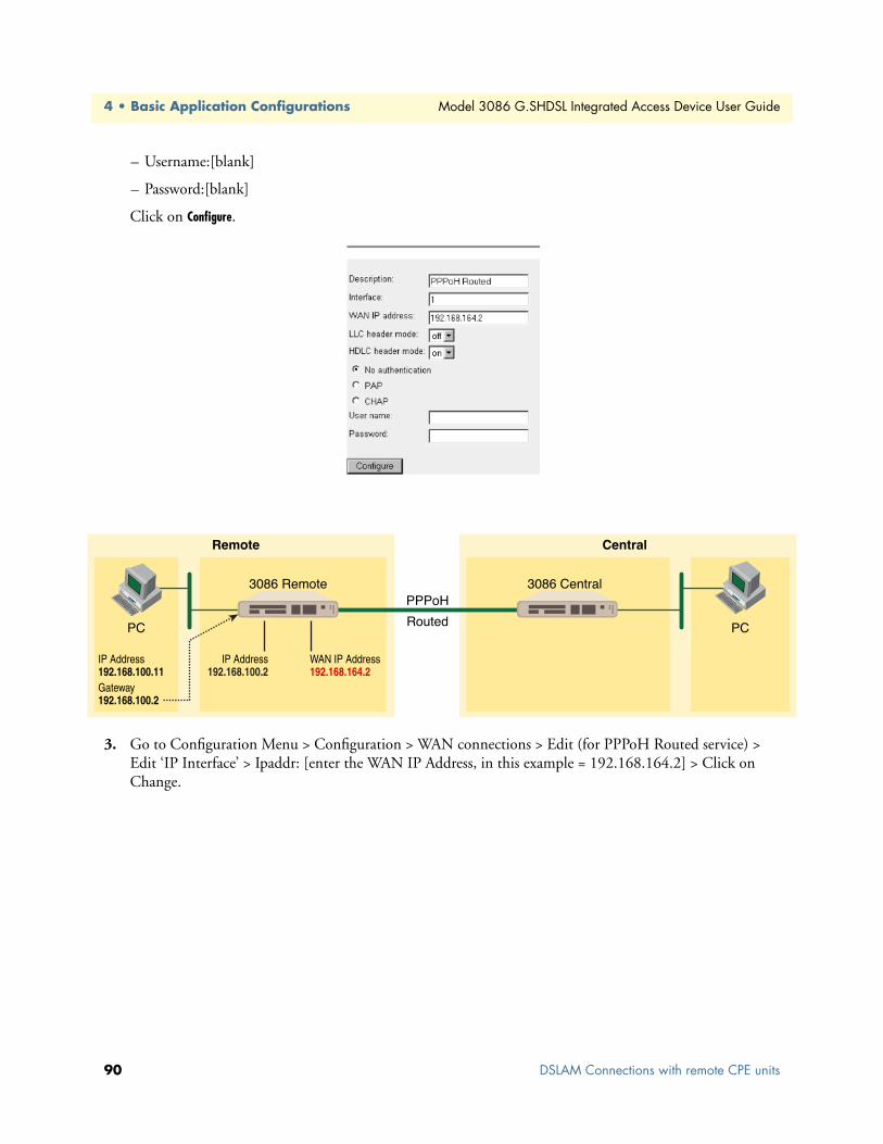
4 • Basic Application Configurations Model 3086 G.SHDSL Integrated Access Device User Guide
– Username:[blank]
– Password:[blank]
Click on Configure.
3. Go to Configuration Menu > Configuration > WAN connections > Edit (for PPPoH Routed service) > Edit ‘IP Interface’ > Ipaddr: [enter the WAN IP Address, in this example = 192.168.164.2] > Click on Change.
90 DSLAM Connections with remote CPE units

Model 3086 G.SHDSL Integrated Access Device User Guide 4 • Basic Application Configurations
4. Configuration Menu > Configuration > IP Routes > Click on Create new Ip V4 Route > Create the gate-way to the remote 3086 by entering the WAN IP address of the remote 3086, in this example, enter 192.168.164.3 in the Gateway field > OK
The other fields should be:
Destination:0.0.0.0
Gateway:192.168.164.3 [already configured in first part of step 5).]
Mask:0.0.0.0
Cost:1
Interface:[blank]
DSLAM Connections with remote CPE units 91

4 • Basic Application Configurations Model 3086 G.SHDSL Integrated Access Device User Guide
5. Go to G.SHDSL in the Configuration Menu, then the submenu Status. The Modem State should be “deactivated.” (If not, go to the Action and change it to deactivate.)
Then in the Action submenu under G.SHDSL, change Action to Start, then click on Action.
Model 3086 (Central) Configuration Steps (PPPoH Routed)
From the command line interface (CLI) via the RS-232 control port,
→ ip list interfaces
→ pppoh clear transports
One IP interface was called ip1 with an IP address of 192.168.1.1
Change the IP address so it is in the same subnet as the laptop PC. The laptop’s IP address is 192.168.172.229, so in this example, change the IP address of the 3086 to 192.168.172.3. The default IP mask is 255.255.255.0.
→ ip set interface ip1 ipaddress 192.168.172.3 255.255.255.0
92 DSLAM Connections with remote CPE units

Model 3086 G.SHDSL Integrated Access Device User Guide 4 • Basic Application Configurations
1. Now you can bring up the web-page management system on your browser by entering the IP address of the 3086.
Click on G.SHDSL in the Configuration Menu > Configuration > verify that Terminal Type is Central and Interface Type is hdlc. If changed, then click on Configure.
Click on Action > Select deactivate for Action > Click on the Action button.
2. On the Menu, go to Configuration, then to WAN Connections.
Delete both default WAN services already defined.
Click on Create a new service in the main window, select PPPoH_Routed and click on the Configure button.
In the Description field, enter the description you wish. In this example, it is called PPPoH Routed.
– Description:PPPoH Routed
– Interface:1
– WAN IP address: 192.168.164.3
– LLC Header Mode:off
– HDLC Header Mode:ON
– No authentication
– Username:[blank]
– Password:[blank]
Click on Configure.
DSLAM Connections with remote CPE units 93

4 • Basic Application Configurations Model 3086 G.SHDSL Integrated Access Device User Guide
3. Go to Configuration Menu > Configuration > WAN connections > Edit (for PPPoH Routed service) > Edit ‘IP Interface’ > Ipaddr: [enter the WAN IP Address, in this example = 192.168.164.3] > Click on Change.
4. Configuration Menu > Configuration > IP Routes > Click on Create new Ip V4 Route > Create the gate-way to the remote 3086 by entering the WAN IP address of the remote 3086, in this example, enter 192.168.164.2 in the Gateway field > OK
The other fields should be:
– Destination:0.0.0.0
– Gateway:192.168.164.2 [already changed in the first part of step 5).]
– Mask:0.0.0.0
– Cost:1
– Interface:[blank]
5. Go to G.SHDSL in the Configuration Menu, then the submenu Status. The Modem State should be “deactivated.” (If not, go to the Action and change it to deactivate.)
Then in the Action submenu under G.SHDSL, change Action to Start, then click on Action.
94 DSLAM Connections with remote CPE units
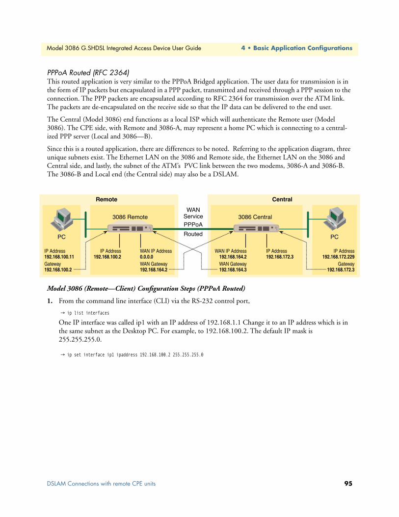
Model 3086 G.SHDSL Integrated Access Device User Guide 4 • Basic Application Configurations
PPPoA Routed (RFC 2364)This routed application is very similar to the PPPoA Bridged application. The user data for transmission is in the form of IP packets but encapsulated in a PPP packet, transmitted and received through a PPP session to the connection. The PPP packets are encapsulated according to RFC 2364 for transmission over the ATM link. The packets are de-encapsulated on the receive side so that the IP data can be delivered to the end user.
The Central (Model 3086) end functions as a local ISP which will authenticate the Remote user (Model 3086). The CPE side, with Remote and 3086-A, may represent a home PC which is connecting to a central-ized PPP server (Local and 3086—B).
Since this is a routed application, there are differences to be noted. Referring to the application diagram, three unique subnets exist. The Ethernet LAN on the 3086 and Remote side, the Ethernet LAN on the 3086 and Central side, and lastly, the subnet of the ATM’s PVC link between the two modems, 3086-A and 3086-B. The 3086-B and Local end (the Central side) may also be a DSLAM.
Model 3086 (Remote—Client) Configuration Steps (PPPoA Routed)
1. From the command line interface (CLI) via the RS-232 control port,
→ ip list interfaces
One IP interface was called ip1 with an IP address of 192.168.1.1 Change it to an IP address which is in the same subnet as the Desktop PC. For example, to 192.168.100.2. The default IP mask is 255.255.255.0.
→ ip set interface ip1 ipaddress 192.168.100.2 255.255.255.0
DSLAM Connections with remote CPE units 95
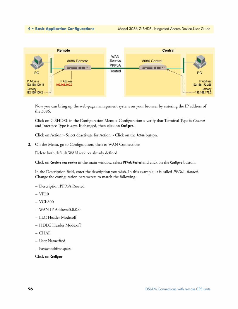
4 • Basic Application Configurations Model 3086 G.SHDSL Integrated Access Device User Guide
Now you can bring up the web-page management system on your browser by entering the IP address of the 3086.
Click on G.SHDSL in the Configuration Menu > Configuration > verify that Terminal Type is Central and Interface Type is atm. If changed, then click on Configure.
Click on Action > Select deactivate for Action > Click on the Action button.
2. On the Menu, go to Configuration, then to WAN Connections
Delete both default WAN services already defined.
Click on Create a new service in the main window, select PPPoA Routed and click on the Configure button.
In the Description field, enter the description you wish. In this example, it is called PPPoA Routed. Change the configuration parameters to match the following.
– Description:PPPoA Routed
– VPI:0
– VCI:800
– WAN IP Address:0.0.0.0
– LLC Header Mode:off
– HDLC Header Mode:off
– CHAP
– User Name:fred
– Passwood:fredspass
Click on Configure.
96 DSLAM Connections with remote CPE units

Model 3086 G.SHDSL Integrated Access Device User Guide 4 • Basic Application Configurations
3. In the Configuration Menu, click on Configuration then > WAN Connections > Edit (for the WAN Ser-vice ppp1) > Edit ‘PPP’ and verify or change the following parameters on the Edit PPP webpage.
– Server:false
– Create Route:true
– Specific Route:false
– Subnet Mask:0.0.0.0
– Route Mask:0.0.0.0
– Hdlc:false
– LLC:false
– Lcp Max Configure:10
– Lcp Max Failure:5
– Lcp Max Terminate:2
– Dialin Auth:none
– Dialout Username:fred
– Dialout Password:fredspass
– Confirmation Password:fredspass
– Dialout Auth:chap
– Interface ID:1
– Remote IP:192.168.164.2
– Local IP:0.0.0.0
– Magic Number:0
– MRU:0
– IP Addr from IPCP:true
DSLAM Connections with remote CPE units 97

4 • Basic Application Configurations Model 3086 G.SHDSL Integrated Access Device User Guide
– Discover Primary DNS:true
– Discover Secondary DNS:true
– Give DNS to Relay:true
– Give DNS to Client:true
– Remote DNS:0.0.0.0
– Remote Secondary:0.0.0.0
– LCP Echo Every:10
– Auto Connect:false
– Idle Timeout:0
– Termination:true
Click on Change button.
4. Click on Edit ‘ATM Channel.’
Verify the Options to match the following. (Change if necessary.)
– Tx Vci:800
– Tx Vpi:0
– Rx Vci:800
– Rx Vpi:0
– Peak Cell Rate:2000
– Burst Tolerance:0
– MCR:0
– MBS:0
– Sustainable Cell Rate:0
98 DSLAM Connections with remote CPE units

Model 3086 G.SHDSL Integrated Access Device User Guide 4 • Basic Application Configurations
– Class:UBR
– Port:atm
Click on the Change button if changes were made.
5. Click on Edit ‘IP Interface.’
Verify or change if necessary the following Options parameters.
– Ipaddr:0.0.0.0
– Mask:0.0.0.0
– Dhcp:false
– MTU:1500
– Enabled:true
Click on the Change button if changes were made.
6. There is no gateway created in the IP routes submenu. Upon connecting, the server will provide this infor-mation while setting up the PPP connection.
7. Go to G.SHDSL in the Configuration Menu, then the submenu Status. The Modem State should be “deactivated.” (If not, go to the Action and change it to deactivate.)
Then in the Action submenu under G.SHDSL, change Action to Start, then click on Action.
Model 3086 (Central—Server) Configuration Steps (PPPoA Routed)
1. From the command line interface (CLI) via the RS-232 control port,
→ ip list interfaces
One IP interface was called ip1 with an IP address of 192.168.1.1 Change it to an IP address which is in the same subnet as the Desktop PC. For example, to 192.168.172.3. The default IP mask is 255.255.255.0.
→ ip set interface ip1 ipaddress 192.168.172.3 255.255.255.0
DSLAM Connections with remote CPE units 99
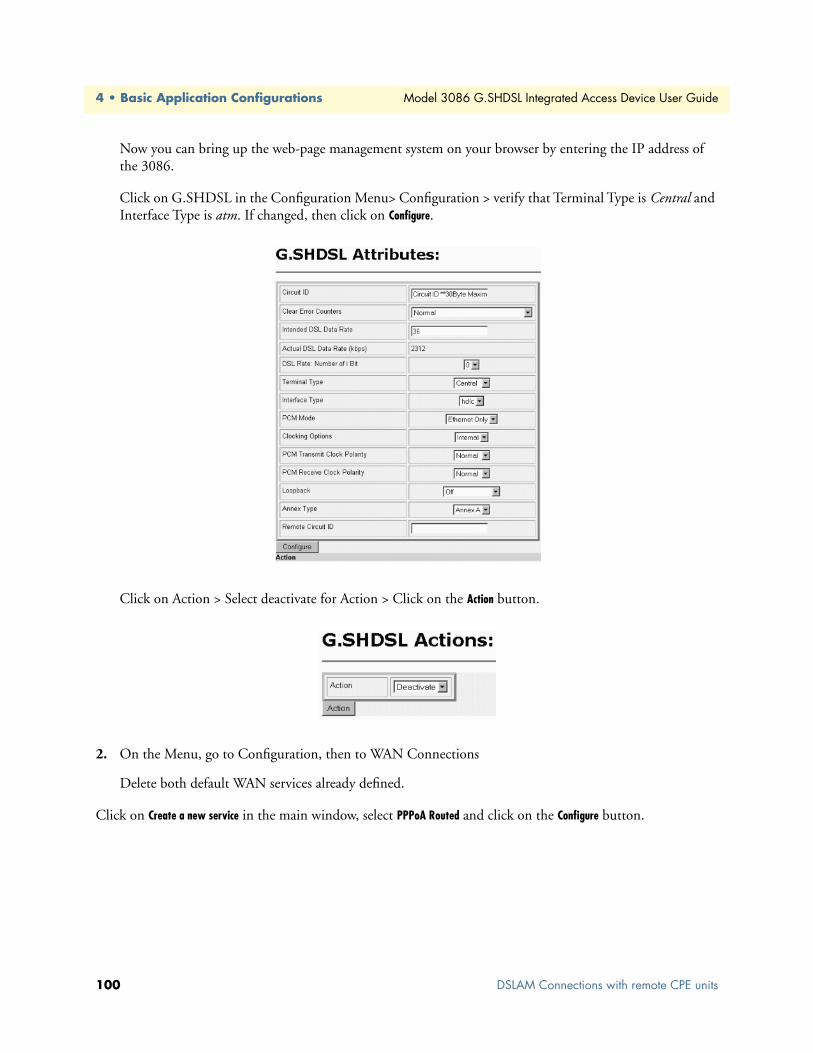
4 • Basic Application Configurations Model 3086 G.SHDSL Integrated Access Device User Guide
Now you can bring up the web-page management system on your browser by entering the IP address of the 3086.
Click on G.SHDSL in the Configuration Menu> Configuration > verify that Terminal Type is Central and Interface Type is atm. If changed, then click on Configure.
Click on Action > Select deactivate for Action > Click on the Action button.
2. On the Menu, go to Configuration, then to WAN Connections
Delete both default WAN services already defined.
Click on Create a new service in the main window, select PPPoA Routed and click on the Configure button.
100 DSLAM Connections with remote CPE units

Model 3086 G.SHDSL Integrated Access Device User Guide 4 • Basic Application Configurations
In the Description field, enter the description you wish. In this example, it is called PPPoA Routed. Change the configuration parameters to match the following.
– Description:PPPoA Routed
– VPI:0
– VCI:800
– WAN IP Address:192.168.164.2
– LLC Header Mode:off
– HDLC Header Mode:off
Note The following items are for dial-out service only, for when a remote is establishing a connection with a server.
• CHAP
• User Name: [leave blank]
• Passwood: [leave blank]
Click on Configure.
DSLAM Connections with remote CPE units 101

4 • Basic Application Configurations Model 3086 G.SHDSL Integrated Access Device User Guide
3. In the Configuration Menu, click on Configuration then > WAN Connections > Edit (for the WAN Ser-vice ppp1) > Edit ‘PPP’ and verify or change the following parameters on the Edit PPP webpage.
Parameters in red italics are those requiring changes from the default configuration.
– Server: true
– Create Route: true
– Specific Route: false
– Subnet Mask: 0.0.0.0
– Route Mask: 0.0.0.0
– Hdlc: false
– LLC: false
– Lcp Max Configure: 10
– Lcp Max Failure: 5
– Lcp Max Terminate: 2
– Dialin Auth: pap
– Dialout Username: [blank]
– Dialout Password: [blank]
– Confirmation Password: [blank]
– Dialout Auth: none
– Interface ID: 2
– Remote IP: 192.168.164.3
– Local IP: 192.168.164.2
– Magic Number: 0
– MRU: 0
102 DSLAM Connections with remote CPE units

Model 3086 G.SHDSL Integrated Access Device User Guide 4 • Basic Application Configurations
– IP Addr from IPCP: true
– Discover Primary DNS: false
– Discover Secondary DNS: false
– Give DNS to Relay: false
– Give DNS to Client: false
– Remote DNS: 0.0.0.0
– Remote Secondary: 0.0.0.0
– LCP Echo Every: 10
– Auto Connect: false
– Idle Timeout: 0
– Termination: true
DSLAM Connections with remote CPE units 103

4 • Basic Application Configurations Model 3086 G.SHDSL Integrated Access Device User Guide
Click on Change button.
104 DSLAM Connections with remote CPE units

Model 3086 G.SHDSL Integrated Access Device User Guide 4 • Basic Application Configurations
4. Click on Edit ‘ATM Channel.’
Verify the Options to match the following. (Change if necessary.)
– Tx Vci:800
– Tx Vpi:0
– Rx Vci:800
– Rx Vpi:0
– Peak Cell Rate:2000
– Burst Tolerance:0
– MCR:0
– MBS:0
– Sustainable Cell Rate:0
– Class:UBR
– Port:atm
Click on the Change button if changes were made.
DSLAM Connections with remote CPE units 105
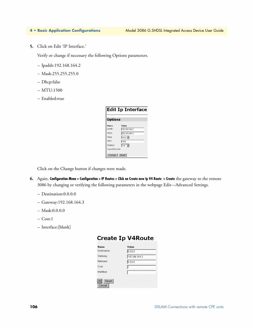
4 • Basic Application Configurations Model 3086 G.SHDSL Integrated Access Device User Guide
5. Click on Edit ‘IP Interface.’
Verify or change if necessary the following Options parameters.
– Ipaddr:192.168.164.2
– Mask:255.255.255.0
– Dhcp:false
– MTU:1500
– Enabled:true
Click on the Change button if changes were made.
6. Again, Configuration Menu > Configuration > IP Routes > Click on Create new Ip V4 Route > Create the gateway to the remote 3086 by changing or verifying the following parameters in the webpage Edit—Advanced Settings.
– Destination:0.0.0.0
– Gateway:192.168.164.3
– Mask:0.0.0.0
– Cost:1
– Interface:[blank]
106 DSLAM Connections with remote CPE units

Model 3086 G.SHDSL Integrated Access Device User Guide 4 • Basic Application Configurations
7. From the Configuration Menu, click on Configuration > Authentication > Create a new user > enter the information for the following parameters in the webpage Details for the new user. One of these authentica-tion records is created for each remote end user connecting to the Server.
– Username:fred
– Password:fredspass
– May dialin:true
– Comments: [may leave blank or enter any comments for this user.]
Click on the Create button.
8. Go to G.SHDSL in the Configuration Menu, then the submenu Status. The Modem State should be “deactivated.” (If not, go to the Action and change it to deactivate.)
Then in the Action submenu under G.SHDSL, change Action to Start, then click on Action.
IPoA Routed (RFC 1577)User data in the form of IP packets is encapsulated into AAL-5 PDUs for transport over ATM. The fact that the user data is routed at an IP layer instead of bridged at a MAC layer allows the source and destination to be on different subnets. A notable drawback of IPoA is the lack of authentication and configuration that would be provided by PPP.
Model 3086 (Remote) Configuration Steps (IPoA Routed)
From the command line interface (CLI) via the RS-232 control port,
→ ip list interfaces
One IP interface was called ip1 with an IP address of 192.168.1.1 Change the IP address so it is in the same subnet as both PCs. For example, to 192.168.100.2. The default IP mask is 255.255.255.0.
→ ip set interface ip1 ipaddress 192.168.100.2 255.255.255.0
DSLAM Connections with remote CPE units 107

4 • Basic Application Configurations Model 3086 G.SHDSL Integrated Access Device User Guide
1. Now you can bring up the web-page management system on your browser by entering the IP address of the 3086.
2. On the Menu, go to Configuration, then to WAN Connections. Delete the factory default WAN services already defined.
Click on Create a new service in the main window, select IPoA_Routed and click on the Configure button.
In the Description field, enter the description you wish. In this example, it is called IPoA Routed.
– VPI:0
– VCI:700
– WAN IP address: 192.168.164.2
Click on Apply.
108 DSLAM Connections with remote CPE units

Model 3086 G.SHDSL Integrated Access Device User Guide 4 • Basic Application Configurations
3. Returning to the 3086 Configuration Menu, click on Configuration, then IP Routes.
– Click on “Create new Ip V4 Route.”
– Destination:0.0.0.0
– Gateway:192.168.164.3
– Mask:0.0.0.0
– Cost:1
– Interface:[leave blank]
Click on OK.
DSLAM Connections with remote CPE units 109

4 • Basic Application Configurations Model 3086 G.SHDSL Integrated Access Device User Guide
4. Go to G.SHDSL in the Configuration Menu, then the submenu Configuration.
Change Terminal Type to Central and Interface Type to atm. Click on the Configure button.
In the Action submenu under G.SHDSL, change Action to Deactivate, then click on Action.
110 DSLAM Connections with remote CPE units

Model 3086 G.SHDSL Integrated Access Device User Guide 4 • Basic Application Configurations
Return to Action, select Start and click on Action.
Model 3086 (Central) Configuration Steps (IPoA Routed)
From the command line interface (CLI) via the RS-232 control port:
→ ip list interfaces
One IP interface was called ip1 with an IP address of 192.168.1.1 Change the IP address so it is in the same subnet as both PCs. For example, to 192.168.172.3. The default IP mask is 255.255.255.0.
→ ip set interface ip1 ipaddress 192.168.172.3 255.255.255.0
1. Now you can bring up the web-page management system on your browser by entering the IP address of the 3086.
2. On the Menu, go to Configuration, then to WAN Connections. Delete the factory default WAN services already defined.
Click on Create a new service in the main window, select IPoA_Routed and click on the Configure button.
In the Description field, enter the description you wish. In this example, it is called IPoA Routed.
– VPI:0
– VCI:700
– WAN IP address: 192.168.164.3
Click on Apply.
DSLAM Connections with remote CPE units 111

4 • Basic Application Configurations Model 3086 G.SHDSL Integrated Access Device User Guide
3. Returning to the 3086 Configuration Menu, click on Configuration, then IP Routes.
Click on “Create new Ip V4 Route.”
– Destination:0.0.0.0
– Gateway:192.168.164.2
– Mask:0.0.0.0
– Cost:1
– Interface:[leave blank]
Click on OK.
4. Go to G.SHDSL in the Configuration Menu, then the submenu Configuration.
Leave Terminal Type as Remote.
Change Interface Type to hdlc. Click on the Configure button.
In the Action submenu under G.SHDSL, change Action to Deactivate, then click on Action.
Return to Action, select Start and click on Action.
112 DSLAM Connections with remote CPE units

Chapter 5 Specialized Configurations
Chapter contentsIP Configurations ................................................................................................................................................114
Router ...........................................................................................................................................................114DHCP Server and Relay ...............................................................................................................................114
113

5 • Specialized Configurations Model 3086 G.SHDSL Integrated Access Device User Guide
IP Configurations
RouterRIP and RIPv2
Static Route
1. Click on > Configuration, then > IP Routes on the Configuration Menu.
2. On the main web page entitled “Edit Routes,” click on Create new Ip V4 Route.
3. Enter the destination IP address in the Value field of “Destination.”
4. Enter the IP address of the gateway which is the WAN IP address of the device on the other end of the DSL link in the Value field of “Gateway.”
5. Enter the appropriate netmask in the Value field of “Netmask.”
6. Leave Cost as “1.”
7. “Interface” is an ASCII field which you may leave blank or fill in for your identification.
8. Click OK.
9. Add additional static routes using the same procedure.
DHCP Server and RelayThe DHCP Server or Relay are simply configured via the web page management pages.
1. Go to > Configuration Menu > Configuration > DHCP Server and the DHCP Server page is displayed.
114 IP Configurations

Model 3086 G.SHDSL Integrated Access Device User Guide 5 • Specialized Configurations
At the bottom of the web page are three options for the DHCP Server Mode: Disabled, DHCP server (default), and DHCP Relay Agent.
2. Click on Configure on the DHCP Server web page to change the configuration for any of the DHCP param-eters.
The three categories of configuration parameters on this web page are the Address Range of the DHCP Server, the Lease Times in seconds, the selection of Domain Name Servers (if desired), and whether to use the router as the default gateway.
3. Clicking on Advanced Options offers additional options for configuration. They are displayed in the following figure.
IP Configurations 115

5 • Specialized Configurations Model 3086 G.SHDSL Integrated Access Device User Guide
4. The IAD may be used as a DHCP Relay Agent if desired. Go to > Configuration Menu > Configuration > DHCP Server. Select DHCP Relay Agent at the bottom of the web page and click on Configure. The DHCP Relay agent page is displayed.
5. Enter the DHCP server’s IP address and click on Apply.
The router is now ready to operate as a DHCP Relay agent.
DNS Client
The DNS client provides a method for retrieving a list of IP addresses for a host name as well as acquiring the host name for a given IP address. The DNS client will cache any results from the name server which reduces network traffic.
1. Enter the DNS Servers by entering the IP address in the field next to the Add button.
2. Click on Add.
More than one DNS Server may be added.
An alternative is to create a domain search list. The DNS Client uses this list when a user asks for the IP address list for an incomplete domain name. There may be up to a maximum of 6 incomplete domain names in the search list.
Enter the domain name and click on Add to add it to the list.
116 IP Configurations

Model 3086 G.SHDSL Integrated Access Device User Guide 5 • Specialized Configurations
DNS Relay Mode
In the DNS Relay web page, up to 10 DNS server addresses may be added to utilize the DNS servers already being used by the network.
1. Select Enabled.
2. Click on Configure.
3. Enter the DNS server address in the field following DNS server IP address:
4. Click on Apply.
5. Repeat to add more DNS server addresses, not to exceed the maximum of 10.
IP Configurations 117

5 • Specialized Configurations Model 3086 G.SHDSL Integrated Access Device User Guide
118 IP Configurations
Chapter 6 Security
Chapter contentsIntroduction ........................................................................................................................................................120
Configuring the IAD...........................................................................................................................................120Configuring the security interfaces.......................................................................................................................121
Deleting a Firewall Policy .............................................................................................................................122Enabling the Firewall...........................................................................................................................................123
Firewall Portfilters ...............................................................................................................................................123Security Triggers..................................................................................................................................................124Intrusion Detection System (IDS) .......................................................................................................................126
119

6 • Security Model 3086 G.SHDSL Integrated Access Device User Guide
IntroductionSecurity provides the ability to setup and enforce security policies. The policies define the types of traffic per-mitted to pass through a gateway, either inbound, outbound, or both, and from which origins the traffic may be allowed to enter.
Within the security configuration is a stateful firewall. A stateful firewall utilizes a security mechanism to main-tain information concerning the packets it receives. This information is used for deciding dynamically whether or not a packet may pass through.
Port filters are rules that determine how a packet should be handled. The rules define the protocol type, the range of source and destination port numbers and an indication whether the packet is allowed or not.
Security triggers are used with applications that require and create separate sessions. The most common exam-ple is FTP. An FTP client establishes a connection to a server using port 21, but data transfers are done on a separate connection or port. The port number, and who makes the connection, can vary depending on the FTP client. To allow FTP to work without triggers, you would need to set up port filters allowing the correct port numbers through. This is a significant security risk.
This risk can be avoided by using security triggers. Triggers tell the security mechanism to expect these second-ary sessions and how to handle them. Rather than allowing a range of port numbers, triggers handle the situa-tion dynamically, opening the secondary sessions only when appropriate. The triggers work without needing to understand the application protocol or reading the payload of the packet, although this does happen when using NAT.
Triggering allows you to set up a trigger for different application protocols that use multiple sessions. The tim-eout between sessions and whether or not session chaining are allowed are configurable. Session chaining is not needed for FTP but is for NetMeeting.
See Chapter 7, “NAT (Network Address Translation)” on page 129.
Configuring the IADThe configuration of security assumes that the 3086/IAD already has a valid IP address for the Ethernet port so that the user may access the modem via the web page. If the IP address is still the factory default, go to the sec-tion in Chapter 3 entitled IP Address Quick Start Modification.
In this example the WAN transport between the two 3086/IADs will be IPoA.
1. Click on WAN Connections under Configuration on the 3086’s Menu.
2. Click on Create a New Service.
3. Select IPoA Routed and click on the Configure button.
4. For this example, enter IPoA Security Firewall in the Description field.
5. VPI remains at 0. Change VCI to be 100.
6. Click on WAN IP address and enter 192.168.101.1 in the adjacent box. The default IP mask is 255.255.255.0.
7. Click on Apply.
120 Introduction

Model 3086 G.SHDSL Integrated Access Device User Guide 6 • Security
The next step in configuring the IAD is adding the default gateway route. Since the WAN IP address of the 3086 modem at the CO site is 192.168.101.2, this will be the gateway for the 3086 modem at the CPE site, the modem we are currently configuring.
1. Click on IP Routes under Configuration on the 3086 modem’s Menu.
2. Click on Create a New IP Route.
3. Enter 192.168.101.2 in the box adjacent to Gateway.
4. Leave Destination and Netmask both as 0.0.0.0 because this is the gateway default route.
5. Click on Create and the route will be entered.
6. The default gateway can be verified by clicking on IP Routes under Status in the menu.
Configuring the security interfacesThe interfaces and routes have been configured on the 3086 IAD which will function as the firewall. The Ethernet side of the 3086 will be configured to be an internal security interface whereas the WAN side is con-figured as an external security interface since it is on “public” side of the modem connection.
1. Click on Security under Configuration on the 3086 modem’s menu.
2. Under Security Interfaces, click on Add Interface.
3. Select Name of the WAN port (ipoa-0) and Interface Type to be external. Click on Apply.
Configuring the security interfaces 121

6 • Security Model 3086 G.SHDSL Integrated Access Device User Guide
4. Add one more security interface by repeating step 2.
5. Select Name of the LAN port (ip1) and Interface Type to be internal. Click on Apply.
Now the Firewall policies will be added between the security interfaces. Only one Firewall policy, called etoi, is added between the external and internal interfaces.
1. Under Policies, Triggers and Intrusion Devices on the Security page, click on Firewall Policy Configuration.
2. In the Current Firewall Policies page, click on New Policy.
3. Select the parameters so the policy applies between interface of types: external internal. Also Validators will block traffic. This blocks all hosts.
4. Click on Apply.
Deleting a Firewall PolicyTo delete a Firewall Policy, follow these Command Line Interface (CLI) commands via the Console port.
→ firewall list policies
122 Configuring the security interfaces

Model 3086 G.SHDSL Integrated Access Device User Guide 6 • Security
Firewall Policies:
ID | Name | Type 1 | Type 2 | Validator Allow Only------------------------------------------------------------------- 1 | item0 | external | internal | false-------------------------------------------------------------------
→ firewall delete policy item0
The firewall policy named item0 is now deleted.
Enabling the FirewallAt this point, both security and the firewall can be enabled and the network is secure. All the interfaces which have been defined are protected: all traffic blocked between the internal and external interfaces.
1. Return to the Security page.
2. Under Security State select Enabled for Security and click on Change State.
3. Then select Enabled for the Firewall and click on Change State.
The network is now secure. All the interfaces which have been defined are protected and all traffic is blocked between different the different interface types. That is, all traffic is blocked between the external and internal interfaces.
The next section describes how to configure the Firewall for allowing certain types of data transfer to occur between the PC’s on different networks.
Firewall PortfiltersNext, we configure the Firewall to permit certain types of data transfer between the PCs on the different net-works. This is done by the implementation of Firewall portfilters. Portfilters are individual rules that determine what kind of traffic can pass between two interface types.
For the Transport Type below, the different types are:
Transport Type Abbreviation
1 ICMP2 IGMP3 GGP4 IP6 TCP8 EGP9 IGP
17 UDP46 RSVP47 GRE89 OSPFIGP92 MTP
Enabling the Firewall 123

6 • Security Model 3086 G.SHDSL Integrated Access Device User Guide
To allow pings between the two PCs:
1. From the Configuration Menu, > Configuration > Security > Firewall Policy Configuration > Port Filters > Add Raw IP Filter
2. Enter 1 (for ICMP) in Transport Type.
3. Both Inbound and Outbound should be allowed.
4. Click on Apply.
You can now ping between the two networks
Security TriggersSecurity triggers are used to allow an application to open a secondary port in order to transport data. The most common example is FTP. This procedure is to set up a trigger on the Firewall to have an FTP session from PC A to PC B, but not the reverse.
1. First, create an outbound-only portfilter for FTP and add it to the item0 policy.
2. Following the path given in step 1 for the ping portfilter, click on Add TCP Filter.
3. The Port Range is entered as 21 for both Start and End.
4. Set Inbound as Block, but Outbound as Allow.
5. Click on Apply.
94 IPIP
Transport Type Abbreviation
124 Security Triggers

Model 3086 G.SHDSL Integrated Access Device User Guide 6 • Security
After configuring the FTP portfilter, you can open an ftp session from Remote to Local, however you can issue ftp commands (e.g., login, cd, etc.) but transfer data (e.g., ls, dir, get, put commands). The portfilter allows an ftp control channel but does not allow the use of a secondary data channel for passing data by ftp.
To enable the ftp data channel, add a trigger which will open a secondary channel only when data is being passed. This prevents the need to open too many ports which offer a security risk.
1. From the Configuration Menu, > Configuration > Security > Firewall Trigger Configuration > New Trig-ger.
2. Set the parameters as follows:
– Transport Type = tcp
– Port Number Start = 21
– Port Number End = 21
– Allow Multiple Hosts = Block
– Max Activity Interval = 3000
– Enable Session Chaining = Block
– Enable UDP Session Chaining = Block
– Binary Address Replacement = Block
– Address Translation Type = none
3. Click on Apply.
You should now be able to use ftp commands to pass data between Remote and Local.
Security Triggers 125

6 • Security Model 3086 G.SHDSL Integrated Access Device User Guide
Intrusion Detection System (IDS)The security feature in the 3086 IAD provides protection from a number of attacks. Some attacks cause a host to be blacklisted (i.e., no traffic from that host is accepted under any circumstances) for a period of time. Other attacks are simply logged. The subsequent table is a summary of the attacks detected.
1. To enable IDS, click on Enabled for “Intrusion Detection Enabled” on the “Security Interface Configura-tion” page. Then click on Change State(s).
2. Click on Configure Intrusion Detection.
3. You may choose which of the parameters to configure and for which value.
– Use Blacklist:Default = 10 minutes when enabled.
If IDS has detected an intrusion an external host, access to the network is denied for ten minutes.
– Use Victim Protection:Default = Disabled.
Enables Victim Protection. Victim Protection protects the victim from an attempted spoofing attack. Web spoofing allows an attacker to create a ‘shadow’ copy of the world wide web (WWW). All access to the shadow Web goes through the attacker’s machine, so the attacker can monitor all of the victim’s activities and send false data to or from the victim’s machine. When enabled, packets destined for the victim host of a spooking style attack are blocked.
– DOS Attack Block Duration:Default = 1800 seconds (30 minutes).
A Denial of Service (DOS) attack is an attempt by an attacker to prevent legitimate users from using a service. If a DOS attack is detected, all suspicious hosts are blocked by the firewall for a set time limit
– Scan Attack Block Duration:Default = 86400 seconds
Attack Name Protocol Attacking Host Blacklisted?
Ascend Kill UDP yesEcho/Chargen UDP noEcho Scan UDP yesWinNuke TCP yes
Xmas Tree Scan TCP yesIMAP SYN/FIN Scan TCP yesSmurf ICMP If victim protection setSYN/FIN/RST Flood TCP If scanning threshold
exceededNet Bus Scan TCP yesBack Orifice Scan UDP yes
126 Intrusion Detection System (IDS)

Model 3086 G.SHDSL Integrated Access Device User Guide 6 • Security
Sets the duration for blocking all suspicious hosts. The firewall detects when the system is being scanned by a suspicious host attempting to identify any open ports.
– Victim Protection Block Duration:Default = 600 seconds (10 minutes).
Sets the duration of the block in seconds.
– Maximum TCP Open Handshaking Count:Default = 100
Sets the maximum number of unfinished TCP handshaking sessions per second that are allowed by a firewall before a SYN Flood is detected. SYN Flood is a DOS attack. When establishing normal TCP connections, three packets are exchanged: (1) A SYN (synchronize) packet is sent from the host to the network server. (2) A SYN/ACK packet is sent from the network server to the host. (3) An Ack (acknowledge) packet is sent from the host to the network server. If the host sends unreachable source addresses in the SYN packet, the server sends the SYN/ACK packets to the unreachable addresses and keeps resending them. This creates a backlog queue of unacknowledged SYN/ACK packets. Once the queue is full, the system will ignore all incoming SYN request and no legitimate TCP connections can be established.
– Once the maximum number of unfinished TCP handshaking sessions is reached, an attempted DOS attack is detected. The firewall blocks the suspected attacker for the time limit specified in the DOS Attack Block Duration parameter.
– Maximum Ping Count:Default = 15
Sets the maximum number of pings per second that are allowed by the firewall before an Echo Storm is detected. Echo Storm is a DOS attack. An attacker sends oversized ICMP datagrams to the system using the ‘ping’ command. This can cause the system to crash, freeze, or reboot, resulting in denial of service to legitimate users.
– Maximum ICMP Count:Default = 100
Sets the maximum number of ICMP packets per second that are allowed by the firewall before an ICMP Flood is detected. An ICMP Flood is a DOS attack. The attacker tries to flood the network with ICMP packets in order to prevent transmission of legitimate network traffic.
4. After selecting the chosen parameters, click on Apply.
Intrusion Detection System (IDS) 127

6 • Security Model 3086 G.SHDSL Integrated Access Device User Guide
128 Intrusion Detection System (IDS)
Chapter 7 NAT (Network Address Translation)
Chapter contentsIntroduction ........................................................................................................................................................130
Enabling NAT ..............................................................................................................................................130Global address pool and reserved map ...........................................................................................................131
129

7 • NAT (Network Address Translation) Model 3086 G.SHDSL Integrated Access Device User Guide
IntroductionThe basic steps for configuring NAT are:
1. Enable NAT between the internal and external interfaces of the firewall.
2. Create global addresses which will be added to the global pool of IP addresses on the WAN interface.
3. Create a reserved mapping between a global IP address and the IP address of an internal PC.
A Global Address Pool is a pool of addresses seen from the outside network. Each external interface creates a Global Address Pool with a single address—the address assigned to that interface. For outbound sessions, an address is picked from a pool by hashing the source IP address for a pool index and then hashing again for an address index. For inbound sessions, it is necessary to create a reserved mapping.
A reserved mapping is used so that NAT knows where to route packets on inbound sessions. The reserved map-ping will map a specific global address and port to an inside address and port. Reserved mappings can also be used so that different inside hosts can share a global address by mapping different ports to different hosts. For example, Host A is an FTP server and Host B is a web server. By mapping the FTP port to Host A and the HTTP port to Host B, both insides hosts can share the same global address. Setting the protocol number to 255 (0xFF) means that the mapping will apply to all protocols. Setting the port number to 65535 (0xFFFF) for TCP or UDP protocols means that the mapping will apply to all port numbers for that protocol.
Some applications embed address and/or port information in the payload of the packet. The most notorious of these is FTP. For most applications, it is sufficient to create a trigger with address replacement enabled. However there are three applications for which a specific ALF is provided: FTP, NetBIOS, and DNS.
Enabling NATThe configuration of NAT in this example follows on the preceding configuration completed in the chapter, “Security.”
1. Go to the “Security Interface Configuration” page by clicking on Security under Configuration in the menu.
2. Click on Enable NAT to internal interfaces in the table, Security Interfaces. NAT is now enabled between the internal (LAN) and the external (WAN) interfaces of the firewall.
130 Introduction

Model 3086 G.SHDSL Integrated Access Device User Guide 7 • NAT (Network Address Translation)
Global address pool and reserved map1. Click on Advanced NAT Configuration… on the web page, “Security Interface Configuration.”
2. Click on the hyperlink Add Global Address Pool. The global IP addresses need to be created and put into the Global Address Pool.
3. Set the parameters to the following values:
– Interface Type:internal
– Use Subnet Configuration:Use IP Address Range
– IP Address:100.100.100.101
– Subnet Mask/IP Address 2:100.100.100.102
Click on Add Global Address Pool.
4. Next, create a reserved mapping between a global IP address from the global pool and an internal PC’s IP address (in this example, 10.1.1.2)
5. Click on Add Reserved Mapping…
Introduction 131
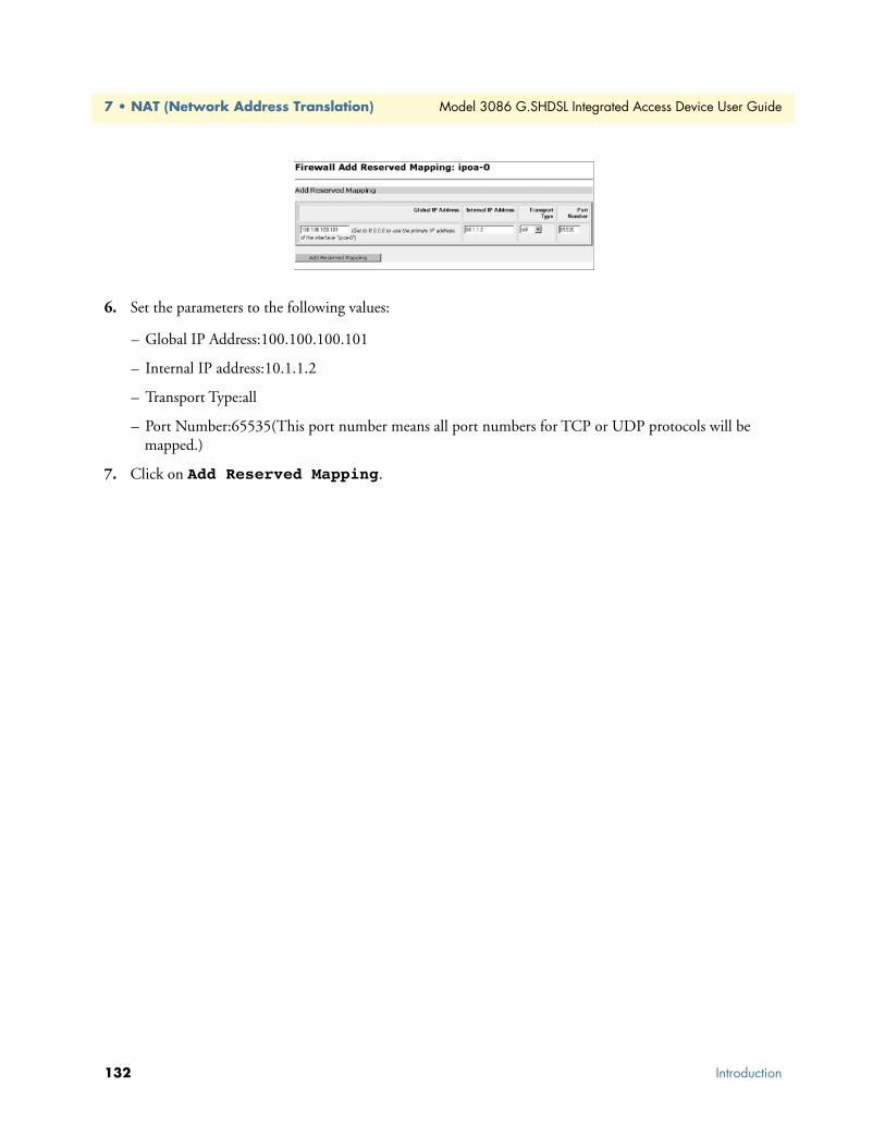
7 • NAT (Network Address Translation) Model 3086 G.SHDSL Integrated Access Device User Guide
6. Set the parameters to the following values:
– Global IP Address:100.100.100.101
– Internal IP address:10.1.1.2
– Transport Type:all
– Port Number:65535(This port number means all port numbers for TCP or UDP protocols will be mapped.)
7. Click on Add Reserved Mapping.
132 Introduction

Chapter 8 Monitoring Status
Chapter contentsStatus LEDs.........................................................................................................................................................134
133

8 • Monitoring Status Model 3086 G.SHDSL Integrated Access Device User Guide
Status LEDsThe LEDs indicate the status of the Power, the WAN (DSL) inter-modem link, Sync Serial or T1/E1 port, the Ethernet connection, and Status.
All LED indicators will present the same looking profile (e.g., clear) when unlit due to being single color, water clear, high efficiency LEDs.
Table 9. Status LED descriptions
Power Green ON indicates that power is applied. Off indi-cates that no power is applied.
WAN (DSL) Link Green Solid green: connectedOff: disconnected
Sync Serial TD Green Green: indicates a binary ‘0’ conditionoff: indicates a binary ‘1’or idle condition
RD Green Green: indicates a binary ‘0’conditionoff: indicates a binary ‘1’ or idle condition
CTS Green ON: indicates the CTS signal from the IAD is active, binary ‘1’off: indicates CTS is binary ‘0’
DTR Green ON: indicates the DTR signal from the DTE device attached to the serial port is active, binary ‘1’
T1/E1 Link Green On: indicates the T1/E1 interface is connected to a live T1/E1 line
LOS Red On: indicates the T1/E1 interface is not connected to an active T1/E1 line
TD Green Green: indicates a binary ‘0’ conditionoff: indicates a binary ‘1’or idle condition
RD Green Green: indicates a binary ‘0’conditionoff: indicates a binary ‘1’ or idle condition
Ethernet Link Green ON: indicates an active 10/100 BaseT connec-tion
100M Green ON: connected to a 100BaseT LANOff: connected to a 10BaseT LAN
Tx Green Flashing: when transmitting data from the IAD to the Ethernet
Rx Green Flashing: when transmitting data from the Ether-net to the IAD.
Status NS Red ON: incidates absence of a valid DSL connec-tion
ER Red flashes once: indicates bit errors occurring dur-ing 511/511E tests
TM Yellow ON: is under one of the test modes (local loop, remote loop, or V.54 BER pattern)
134 Status LEDs

Chapter 9 Diagnostics
Chapter contentsIntroduction ........................................................................................................................................................136
Ping.....................................................................................................................................................................136Software Upgrades...............................................................................................................................................136
Configuration ...............................................................................................................................................136Procedure ......................................................................................................................................................136
Operating Local Analog Loopback (LAL)—Serial Port Loop...............................................................................137Operating Remote Digital Loopback (RDL)—DSL Loop ...................................................................................137T1/E1 Diagnostics...............................................................................................................................................138
Network Loop ..............................................................................................................................................138T1/E1 Local Loop .........................................................................................................................................139QRSS—BIT Error Rate Diagnostics .............................................................................................................140T1/E1 connection Status ..............................................................................................................................141
Alarms .....................................................................................................................................................141Transceiver Status. ..................................................................................................................................141FDL statistics (T1 only) ..........................................................................................................................141E1/T1 DS0 Monitor ...............................................................................................................................141
BIT Error Rate (V.52) Diagnostics ......................................................................................................................142
135

9 • Diagnostics Model 3086 G.SHDSL Integrated Access Device User Guide
IntroductionThe Model 3086 offers three sets of diagnostics: Local Analog Loopback (serial port loop), Remote Digital Loopback (DSL loop), and T1/E1 Loops for the Model 3086/K. Some tests can be activated physically from the front panel, or via the CLI/Web management menus
PingThe ping command is executed from the Command Line Interface (CLI). Ping in the 3086 is executed from the “ip” command. Here is the ping format followed by a valid response.
ip ping 192.168.100.11ping: PING 192.168.100.11: 32 data bytesping: 40 bytes from 192.168.100.11: seq=0, ttl=128, rtt<10ms
→
Software UpgradesSoftware upgrades are required in two scenarios. First, for new features. Second, for standard software upgrades (at an additional cost).
For standard software upgrades, which are at no charge, contact upgrades.patton.com for the location of the new firmware and follow these instructions.
1. Get the firmware image from Patton and save on your PC. It is a .tar file and MUST NOT be unzipped!
2. Login to the 3086’s web page on the browser.
3. Click on > System, then > Upgrade
4. Locate the firmware image on this web page.
5. Click on Upgrade.
6. Wait until the upgrading is complete, and then restart the 3086.
7. It is now ready to use with the new firmware.
If you encounter problems with the firmware upgrade, do the following to upload software image into the Pat-ton 3086 via TFTP. .
Note The Patton 3086 products have a TFTP server built-in, a TFTP cli-ent will be require on the user side to connect to the TFTP server
ConfigurationThe Patton products are configured as a TFTP server with the default IP address 192.168.200.10.
Procedure1. Go to Upgrade.patton.com and download the software upload package. The package contains the follow-
ing files:
– Tftplock.key
– Tftpupdt.beg
– Image
136 Introduction

Model 3086 G.SHDSL Integrated Access Device User Guide 9 • Diagnostics
– Npimage
– Key
– Initbun
– Im.conf
– Tftpupdt.rbt
– Tftpupdt.end
– Script.bat
2. Connect the control (console) port of the unit to a PC.
3. Connect the Ethernet port to the appropriate device where the upload package will be stored.
4. On a Window 2000 or WinXP machine, open a Command Prompt and run the script. (The script will connect to the default 192.168.200.10 IP address). If using Win9x, a TFTP client will be needed.
5. The TFTP process takes about 90 seconds, the unit will reboot automatically when done.
Operating Local Analog Loopback (LAL)—Serial Port LoopThe Local Line Loopback (LAL) applies to serial port data traffic, it does not affect traffic from the Ethernet port. The local Loop test checks the operation of the local Model 3086, and is performed separately on each unit. Any data sent to the local Model 3086 in this test mode will be echoed (returned) to the user device (i.e, characters typed on the key-board of a terminal will appear on the terminal screen).
Figure 12. Local Line Loop
To perform a Local Analog Loopback test, follow these steps:
1. Move the front panel toggle switch UP to Local.
2. Verify that the data terminal equipment is operating properly and can be used for a test.
3. Perform a V.52 BER (bit error rate) test as described in secton “BIT Error Rate (V.52) Diagnostics” If the BER test equipment indicates no faults, but the data terminal indicates a fault, follow the manufacturer’s checkout procedure for the data terminal. Also check the interface cable between the terminal and the Model 3086.
Operating Remote Digital Loopback (RDL)—DSL LoopThe Remote Digital Loopback (RDL) test checks the performance of both the local and remote Model 3086s, as well as the communication link between them. Any characters originating at the serial port and sent to the remote Model 3086 in the test mode will be returned to the originating device (i.e, characters typed on the
Operating Local Analog Loopback (LAL)—Serial Port Loop 137

9 • Diagnostics Model 3086 G.SHDSL Integrated Access Device User Guide
keyboard of the local terminal will appear on the local terminal screen after having been passed to the remote Model 3086 and looped back). See Figure 13.
Figure 13. Remote Digital Loop
To perform an RDL test, follow these steps:
1. Activate the RDL by moving the front panel toggle switch DOWN to remote.
2. Perform a bit error test (BERT) using the internal V.52 generator (as described in section “BIT Error Rate (V.52) Diagnostics” on page 142), or using a seperate BER Tester. If the BER test indicates a fault, and the Local Line Loopback test was successful for both Model 3086s, you may have a problem with the twisted pair line between the modems. You should then check the twisted pair line for proper connections and continuity.
T1/E1 Diagnostics The 3086/K offers two diagnostics loops for the T1/E1 interface: Network (line) loopback, and local loop, These tests can be activated via the CLI/Web management menus
Network Loop The Network (line) Loopback applies to the T1/E1 interface data traffic; it does not affect traffic from the Ethernet port. The network Loop test verifies the operation of the T1/E1interface of the local unit and the T1/E1 line. Any data received by the 3086 T1/E1 interface in this test mode will be echoed (returned) to the orig-inating device. This test is useful when the device connected to the 3086’s T1/E1 interface is unable to send loop codes to the local 3086’s T1/E1 CSU/DSU interface.
Figure 14. 3086 Line Loop
Remote 3086
DSL
Crossover
10/100
Ethernet
Power
MDI-X
Crossover
10/100
Ethernet
Power
MDI-X
Local 3086
138 T1/E1 Diagnostics

Model 3086 G.SHDSL Integrated Access Device User Guide 9 • Diagnostics
To set the 3086 T1/E1 port in Network Loopback test, do the following:
1. Go to the 3086 Main page, select E1/T1. Next, click on Test Modes, select network Loop using the drop down menu, click on the Activate Test Mode button.
2. Perform a BER (bit error rate) test. Replace the Local T1/E1 equipment (PBX) with a T1/E1 tester, and initiate a BER test to verify integrity of the cable and operation of the 3086’s T1 interface.
T1/E1 Local Loop When set to local loop, the 3086/K loops DSL timeslots assigned to carry T1/E1 data to far end 3086 or 3096RC T-DACS.
Figure 15. 3086/K T1/E1 local loop
To set the 3086 in T1/E1 local loop test, follow these steps:
T1/E1 Diagnostics 139

9 • Diagnostics Model 3086 G.SHDSL Integrated Access Device User Guide
1. Go to the 3086 Main page, select E1/T1. Next, click on Test Modes, select local Loop using the drop down menu, click on the Activate Test Mode button.
2. Perform a BER (bit error rate) test. This test can be initiated from the far end using a T1/E1 BER tester to verify the T1/E1 path over the DSL line and 3086s involved.
QRSS—BIT Error Rate DiagnosticsThe 3086/K offers a Bit Error Rate (BER) QRSS test pattern. This test pattern may to be used to test the com-munication link and the T1/E1 interface of the device attached to the 3086. When a QRSS test is invoked, the 3086 generates a pseudo-random pattern using a mathematical polynomial. The pattern is sent over the T1/E1 interface to the far end device and looped to the 3086 (originator), the far end device i.e. PBX or routers’s T1/E1 port must be set to line loop. The local 3086 decodes the received bits using the same polynomial. If the received bits match the agreed upon pseudo-random pattern, then the 3086 and the communication link are functioning properly. The 3086 can also initiate a built-in QRSS pattern with errors. This test pattern genera-tor injects intentional errors approximately once per second in the transmitted stream.
To perform a BER test, follow these steps:
1. From the Main page T1/E1 option, select the QRSS or QRSS Errs option, and then click on the Activate Test Mode button. This will start the internal test pattern generator for data sent and looped at the far end device.
2. Monitor the BER test results. The Test Mode Status window will display the number of bit errors, if any, detected in the received stream.
Note The above BER tests will not work if the 3086’s T1/E1 interface has been placed in Network loop.
140 T1/E1 Diagnostics
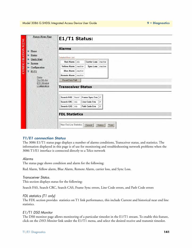
Model 3086 G.SHDSL Integrated Access Device User Guide 9 • Diagnostics
T1/E1 connection StatusThe 3086 E1/T1 status page displays a number of alarms conditions, Transceiver status, and statistics. The information displayed in this page is of use for monitoring and troubleshooting network problems when the 3086 T1/E1 interface is connected directly to a Telco network
Alarms The status page shows condition and alarm for the following:
Red Alarm, Yellow alarm, Blue Alarm, Remote Alarm, carrier loss, and Sync Loss.
Transceiver Status.This section displays status for the following:
Search FAS, Search CRC, Search CAS, Frame Sync errors, Line Code errors, and Path Code errors
FDL statistics (T1 only) The FDL section provides statistics on T1 link performance, this include Current and historical near end line statistics.
E1/T1 DS0 Monitor The DS0 monitor page allows monitoring of a particular timeslot in the E1/T1 stream. To enable this feature, click on the DSO Monitor link under the E1/T1 menu, and select the desired receive and transmit timeslot.
T1/E1 Diagnostics 141

9 • Diagnostics Model 3086 G.SHDSL Integrated Access Device User Guide
BIT Error Rate (V.52) DiagnosticsThe Model 3086 offers a V.52 Bit Error Rate (BER) 511 test pattern. This test pattern may be invoked along with the LAL and RDL tests to evaluate the unit(s) and the DSL communication links. When a 511 test is invoked, the 3086 generates a pseudo-random pattern of 511 bits using a mathematical polynomial. The receiving Model 3086 then decodes the received bits using the same polynomial.
If the received bits match the agreed upon pseudo-random pattern, then the 3086(s) and the communication link(s) are functioning properly. 511 Initiates a built-in 511 bit pseudo-random pattern generator and detector. 511 with Errors Initiates a built-in 511 bit pseudo-random pattern generator and detector. The test pattern generator also injects intentional errors approximately once per second, causing the Error LED to blink.
To perform a V.52 BER test, follow these steps:
1. Locate the toggle switch group on the right side on the front panel and place it in the middle where it is marked “Normal”. This activates the V.52 transmission and reception of the selected test pattern. If there are errors in the received pattern, the error LED will blink accordingly.
2. If the above test indicates no errors are present, move the toggle switch UP to 511/E, activating the BER test with intentional errors. If the test light is working properly, the local modem’s red error LED will blink approximately once per second.
Note The above V.52 BER tests can be used independently of the Remote Digital Loopback tests.
142 BIT Error Rate (V.52) Diagnostics
Chapter 10 Contacting Patton for assistance
Chapter contentsIntroduction ........................................................................................................................................................144
Contact information............................................................................................................................................144Warranty Service and Returned Merchandise Authorizations (RMAs).................................................................144
Warranty coverage ........................................................................................................................................144Out-of-warranty service ...........................................................................................................................144
Returns for credit ....................................................................................................................................144Return for credit policy ...........................................................................................................................145
RMA numbers ..............................................................................................................................................145
Shipping instructions ..............................................................................................................................145
143

10 • Contacting Patton for assistance Model 3086 G.SHDSL Integrated Access Device User Guide
IntroductionThis chapter contains the following information:
• “Contact information”—describes how to contact PATTON technical support for assistance.
• “Warranty Service and Returned Merchandise Authorizations (RMAs)”—contains information about the RAS warranty and obtaining a return merchandise authorization (RMA).
Contact informationPatton Electronics offers a wide array of free technical services. If you have questions about any of our other products we recommend you begin your search for answers by using our technical knowledge base. Here, we have gathered together many of the more commonly asked questions and compiled them into a searchable database to help you quickly solve your problems.
• Online support—available at www.patton.com.
• E-mail support—e-mail sent to [email protected] will be answered within 1 business day
• Telephone support—standard telephone support is available 5 days a week, from 8:00am to 5:00pm EST by calling +1 (301) 975-1007
Warranty Service and Returned Merchandise Authorizations (RMAs)Patton Electronics is an ISO-9001 certified manufacturer and our products are carefully tested before ship-ment. All of our products are backed by a comprehensive warranty program.
Note If you purchased your equipment from a Patton Electronics reseller, ask your reseller how you should proceed with warranty service. It is often more convenient for you to work with your local reseller to obtain a replacement. Patton services our products no matter how you acquired them.
Warranty coverageOur products are under warranty to be free from defects, and we will, at our option, repair or replace the prod-uct should it fail within one year from the first date of shipment. Our warranty is limited to defects in work-manship or materials, and does not cover customer damage, lightning or power surge damage, abuse, or unauthorized modification.
Out-of-warranty servicePatton services what we sell, no matter how you acquired it, including malfunctioning products that are no longer under warranty. Our products have a flat fee for repairs. Units damaged by lightning or other catastro-phes may require replacement.
Returns for creditCustomer satisfaction is important to us, therefore any product may be returned with authorization within 30 days from the shipment date for a full credit of the purchase price. If you have ordered the wrong equipment or you are dissatisfied in any way, please contact us to request an RMA number to accept your return. Patton is not responsible for equipment returned without a Return Authorization.
144 Introduction

Model 3086 G.SHDSL Integrated Access Device User Guide 10 • Contacting Patton for assistance
Return for credit policy • Less than 30 days: No Charge. Your credit will be issued upon receipt and inspection of the equipment.
• 30 to 60 days: We will add a 20% restocking charge (crediting your account with 80% of the purchase price).
• Over 60 days: Products will be accepted for repairs only.
RMA numbersRMA numbers are required for all product returns. You can obtain an RMA by doing one of the following:
• Completing a request on the RMA Request page in the Support section at www.patton.com
• By calling +1 (301) 975-1000 and speaking to a Technical Support Engineer
• By sending an e-mail to [email protected]
All returned units must have the RMA number clearly visible on the outside of the shipping container. Please use the original packing material that the device came in or pack the unit securely to avoid damage during shipping.
Shipping instructionsThe RMA number should be clearly visible on the address label. Our shipping address is as follows:
Patton Electronics CompanyRMA#: xxxx7622 Rickenbacker Dr.Gaithersburg, MD 20879-4773 USA
Patton will ship the equipment back to you in the same manner you ship it to us. Patton will pay the return shipping costs.
Warranty Service and Returned Merchandise Authorizations (RMAs) 145

10 • Contacting Patton for assistance Model 3086 G.SHDSL Integrated Access Device User Guide
146 Warranty Service and Returned Merchandise Authorizations (RMAs)

Appendix A Compliance information
Chapter contentsCompliance .........................................................................................................................................................148
EMC .............................................................................................................................................................148Safety ............................................................................................................................................................148PSTN Regulatory ..........................................................................................................................................148
Radio and TV Interference (FCC Part 15) ..........................................................................................................148
CE Declaration of Conformity ............................................................................................................................148Authorized European Representative ...................................................................................................................149FCC Part 68 (ACTA) Statement .........................................................................................................................149
Industry Canada Notice ......................................................................................................................................149
147

Model 3086 G.SHDSL Integrated Access Device User Guide A • Compliance information
Compliance
EMC • FCC Part 15, Class A
• EN55022, Class A
• EN55024
Safety• UL60950-1/CSA C22.2 No. 60950-1
• IEC/EN 60950-1
• AS/NZS 60950-1
PSTN Regulatory• FCC Part 68
• CS-03
• AS/ACIF S043
Radio and TV Interference (FCC Part 15)This equipment generates and uses radio frequency energy, and if not installed and used properly—that is, in strict accordance with the manufacturer's instructions—may cause interference to radio and television recep-tion. This equipment has been tested and found to comply with the limits for a Class A computing device in accordance with the specifications in Subpart B of Part 15 of FCC rules, which are designed to provide reason-able protection from such interference in a commercial installation. However, there is no guarantee that inter-ference will not occur in a particular installation. If the equipment causes interference to radio or television reception, which can be determined by disconnecting the cables, try to correct the interference by one or more of the following measures: moving the computing equipment away from the receiver, re-orienting the receiving antenna, and/or plugging the receiving equipment into a different AC outlet (such that the computing equip-ment and receiver are on different branches).
CE Declaration of ConformityWe certify that the apparatus identified in this document conforms to the requirements of Council Directive 1999/5/EC on the approximation of the laws of the member states relating to Radio and Telecommunication Terminal Equipment and the mutual recognition of their conformity.
The safety advice in the documentation accompanying this product shall be obeyed. The conformity to the above directive is indicated by the CE sign on the device.
Compliance 148

Model 3086 G.SHDSL Integrated Access Device User Guide A • Compliance information
Authorized European RepresentativeD R M Green
European Compliance Services Limited.
Avalon House, Marcham Road
Abingdon,
Oxon OX14 1UD, UK
FCC Part 68 (ACTA) Statement
This equipment complies with Part 68 of FCC rules and the requirements adopted by ACTA. On the bottom side of this equipment is a label that contains—among other information—a product identifier in the format US: AAAEQ##TXXXX. If requested, this number must be provided to the telephone company.
A plug and jack used to connect this equipment to the premises wiring and telephone network must comply with the applicable FCC Part 68 rules and requirements adopted by the ACTA.
This equipment uses a Universal Service Order Code (USOC) jack: RJ-11C.
If this equipment causes harm to the telephone network, the telephone company will notify you in advance that temporary discontinuance of service may be required. But if advance notice isn’t practical, the telephone company will notify the customer as soon as possible. Also, you will be advised of your right to file a complaint with the FCC if you believe it is necessary.
The telephone company may make changes in its facilities, equipment, operations or procedures that could affect the operation of the equipment. If this happens the telephone company will provide advance notice in order for you to make necessary modifications to maintain uniterrupted service.
If trouble is experienced with this equipment, for repair or warranty information, please contact our company. If the equipment is causing harm to the telephone network, the telephone company may request that you dis-connect the equipment until the problem is resolved.
Connection to party line service is subject to state tariffs. Contact the state public utility commission, public service commission or corporation commission for information.
Industry Canada NoticeThis equipment meets the applicable Industry Canada Terminal Equipment Technical Specifications. This is confirmed by the registration number. The abbreviation, IC, before the registration number signifies that regis-tration was performed based on a Declaration of Conformity indicating that Industry Canada technical speci-fications were met. It does not imply that Industry Canada approved the equipment.
This Declaration of Conformity means that the equipment meets certain telecommunications network protec-tive, operational and safety requirements. The Department does not guarantee the equipment will operate to the user's satisfaction. Before installing this equipment, users should ensure that it is permissible to be con-nected to the facilities of the local telecommunications company. The equipment must also be installed using an acceptable method of connection. In some cases, the company's inside wiring associated with a single line individual service may be extended by means of a certified connector assembly (telephone extension cord). The customer should be aware that compliance with the above condition may not prevent degradation of service in
Authorized European Representative 149

Model 3086 G.SHDSL Integrated Access Device User Guide A • Compliance information
some situations. Repairs to some certified equipment should be made by an authorized maintenance facility designated by the supplier. Any repairs or alterations made by the user to this equipment, or equipment mal-functions, may give the telecommunications company cause to request the user to disconnect the equipment. Users should ensure for their own protection that the ground connections of the power utility, telephone lines and internal metallic water pipe system, are connected together. This protection may be particularly important in rural areas.
Industry Canada Notice 150

Appendix B Specifications
Chapter contentsGeneral Characteristics ........................................................................................................................................152
G.SHDSL Characteristics....................................................................................................................................152Ethernet ..............................................................................................................................................................152Sync Serial Interface ............................................................................................................................................153T1/E1 Interface (3086/RIK and RIT models only) .............................................................................................153
64K/G.703 Port (3086/RIF Model) ...................................................................................................................153Protocol Support .................................................................................................................................................153PPP Support........................................................................................................................................................154
ATM Protocols....................................................................................................................................................154Management .......................................................................................................................................................154Security ...............................................................................................................................................................155Compliance Standard Requirements....................................................................................................................155
Australia Specific .....................................................................................................................................155Dimensions .........................................................................................................................................................155Power and Power Supply Specifications...............................................................................................................155
AC universal power supply ......................................................................................................................15548 VDC power supply ............................................................................................................................155
151

B • Specifications Model 3086 G.SHDSL Integrated Access Device User Guide
General Characteristics• Compact low-cost plug and play IAD
• 10/100 Ethernet
• Unlimited host support.
• Comprehensive hardware diagnostics, works with any operating system, easy maintenance and effortless installation.
• Plug-and-Play operation for fast and seamless turn-up with pre-configured WAN and LAN options.
• Built-in web configuration.
• Setup allows for standard IP address and unique method for entering an IP address and mask WITHOUT use of a console connection. Default IP address of 192.168.1.1/24.
• Simple software upgrade using FTP into FLASH memory.
• Eight front panel LEDs indicate Power, DSL WAN, Ethernet LAN speed and status.
• Convenient and standard RJ connectors for Ethernet, Line, and Console.
• Field Factory Default Option.
• Standard 1 year warranty.
G.SHDSL Characteristics• Full duplex 2.3 Mbps speed over 2-wire (in accordance with ETSI/ITU standard G.991.2). 2.3 Mbps to
4.6 Mbps, full duplex, over 2-wire.
• DTE Rates 64 kbps to 2.32 Mbps operation. With nx64 with n=1 support.
• Distance from 24,900 feet (7,590 meters) at 192 kbps to 10,200 feet (3,109 meters) at 2.3 Mbps on 26 AWG (0.4 mm) wire
• Annex A (ANSI), Annex B (ETSI) PSD selection.
• 2 wire or 4 wire support (4-wire support to be keyed) for multiple line codes per ITU G.991.2 and ETSI TS 101524 with G.994.1 Handshake.
• CO and CP modes are supported
• TC-PAM based DSL modulations.
• EOC Management channel for remote end-to-end management.
Ethernet • Auto-sensing Full-Duplex 10Base-T/100Base-TX Ethernet.
• Standard RJ-45 and built-in MDI-X cross-over switch.
• IEEE 8021.d transparent learning bridge up to 1,024 addresses and Spanning Tree.
• 8 IP address/subnets on Ethernet interface.
152 General Characteristics
Model 3086 G.SHDSL Integrated Access Device User Guide B • Specifications
Sync Serial Interface • ITU X.21 or V.35 interface
• Available with Female M34, DB-25, and DB-15 connectors
• User configurable DTE/DCE for X.21
T1/E1 Interface (3086/RIK and RIT models only) • Line Rate 1.544 Mbps (T1), and 2.048 Mbps (E1)
• RJ-48C connector ( with optional Dual BNC for RIK version)
• DSX-1 levels for connection to local T1/E1 device (PBX).
• Nx56/64 kbps with full DS0 mapping
• AMI/B8ZS (T1), AMI/HDB3 (E1)
• D4/ESF coding and framing (T1)
64K/G.703 Port (3086/RIF Model)• Line rate 256 kbps
• Data rate 64 kbps
• RJ-48C connector
• AMI Line Coding
Protocol Support• Complete internetworking with IP (RFC 741), TCP (RFC 793), UDP (RFC 768), ICMP (RFC 950),
ARP (RFC 826).
• IP Router with RIP (RFC 1058), RIPv2 (RFC 2453),
• Up to 64 static routes with user selectable priority over RIP/OSPF routes.
• Built-in ping facilities.
• Integrated DHCP Server (RFC 2131). Selectable general IP leases and user specific MAC/IP parings. Selectable lease period.
• DHCP relay agent (RFC 2132/RFC 1542) with 8 individual address pools.
• DNS Relay with primary and secondary Name Server selection.
• NAT (RFC 3022) with Network Address Port Translation (NAPT) for cost-effective sharing of a single DSL connection. Integrated Application Level Gateway with support for over 80 applications.
• NAT MultiNat with 1:1 mapping.
• NAT Many:1.
• NAT Many:Many mapping.
• NAT Port/IP redirection and mapping.
Sync Serial Interface 153

B • Specifications Model 3086 G.SHDSL Integrated Access Device User Guide
• uPNP controlled device for seamless networked device interconnectivity and Windows XP integration.
• IGMPv2 Proxy support (RFC 2236).
• Frame Relay with Annex A/D/LMI, RFC 1490 MpoFR and FRF.12 Fragmentation.
PPP Support• Point-to-Point Protocol over HDLC
• PPPoA (RFC 2364) Point-to-Point Protocol over ATM.
• PPPoE (RFC 2516) Client for autonomous network connection. Eliminates the requirement of installing client software on a local PC and allows sharing of the connection across a LAN.
• User configurable PPP PAP (RFC 1661) or CHAP (RFC 1994) authentication.
• PPP BCP (RFC 1638) support for bridged networking support.
ATM Protocols• Multiprotocol over ATM AAL5 and Multiprotocol Bridged encapsulation RFC 2684 (Formerly RFC
1483) and RFC 1577 Classical IP over ATM. Default RFC-1483 route mode. Logical Link Control (LLC)/ Subnetwork Access Protocol (SNAP) encapsulation. Default VC mux mode.
• ATM UNI 3.0, 3.1, and 4.0 signaling ATM QoS with UBR, CBR, nrt-VBR, and rt-VBR and per-VC queuing and shaping. IISP V.1.0 Q.2931 UNI L3 and Q.2971 UNI L3 support.
• LAN Emulation Client (LEC) V.1 with LEC via PVC or ILMI connection.
• Peak cell rate shaping on a per-VCC basis up to 32 active VCCs across VPI 0-255, VCI 0-65525. Single default PVC: 8/35 with PCR=5,500 cells.
• I.610 OAM network management including AIS/RDI, loop-back and performance monitoring.
• Enhanced ILMI 4.0 for auto-configuration of ATM PVCs.
Management• User selectable ATM, PPP, or Frame Relay WAN datalink connection.
• Web-Based configuration via embedded web server
• CLI menu for configuration, management, and diagnostics.
• Local/Remote CLI (VT-100 or Telnet).
• SNMPv1 (RFC 1157) MIB II (RFC 1213)
• Quick Start Setup runs through common options to simplify circuit turn-up.
• Logging via SYSLOG, and VT-100 console. Console port set at 9600 bps 8/N/1 settings no flow control.
• EOC access for End-To-End management, configuration, and control.
154 PPP Support

Model 3086 G.SHDSL Integrated Access Device User Guide B • Specifications
Security• Packet filtering firewall for controlled access to and from LAN/WAN. Support for 255 rules in 32 filter sets.
16 individual connection profiles.
• DoS Detection/protection. Intrusion detection, Logging of session, blocking and intrusion events and Real-Time alerts. Logging or SMTP on event.
• Password protected system management with a username/password for console and virtual terminal. Sepa-rate user selectable passwords for SNMP RO/RW strings.
• Access list determining up to 5 hosts/networks which are allowed to access management system SNMP/HTTP/TELNET.
• Logging or SMTP on events: POST, POST errors, line/DSL, PPP/DHCP, IP.
Compliance Standard Requirements• FCC part 15 Class A (US EMC)
• CE per RTTE 99/5/EC (EMC & LVD)
• FCC Part 68 ( – US Permission to connect)
• CTR 12 & CTR 13
• IC-CS03 (Canadian Permission to connect)
• Safety – EN60950
Australia Specific• TS016 (E1 Telecom)
• AZ/NZS 3260 Safety)
• AZ/NZS 35-48 EMC
Dimensions1.58H x 4.16W x 3.75D in. (10.6H x 4.1W x 8.8D cm)
Power and Power Supply SpecificationsThe 3086 may come with either an AC or DC power supply.
AC universal power supplyThe Model 3086 offers internal or external AC power supply options.
• The internal power supply connects to an AC source via an IEC-320 connector (100–240 VAC, 200 mA, 50/60 Hz)
• The external power supply connects to an external source providing +5 VDC via a barrel-type connector
48 VDC power supply• Rated voltage and current: 36–60 VDC, 400 mA
Security 155

B • Specifications Model 3086 G.SHDSL Integrated Access Device User Guide
• Fuse rating: 250 Volts, 400 mA, time delay
Connect the equipment to a 36–60 VDC source that is electri-cally isolated from the AC source. The 36–60 VDC source is to be reliably connected to earth.
156 Power and Power Supply Specifications

Appendix C Cable Recommendations
Chapter contentsDSL Cable...........................................................................................................................................................158
Ethernet Cable ....................................................................................................................................................158Adapter................................................................................................................................................................158
157
C • Cable Recommendations Model 3086 G.SHDSL Integrated Access Device User Guide
DSL Cable10 foot (3 m), RJ-11/RJ-11 (refer to “RJ-11 non-shielded port” on page 160)
Ethernet CableEthernet cable (P/N 10-2500) (refer to “RJ-45 shielded 10/100 Ethernet port” on page 160)
AdapterEIA-561 to DB-9 (P/N 16F-561) (refer to “RJ-45 non-shielded RS-232 console port (EIA-561)” on page 160)
158 DSL Cable

Appendix D Physical Connectors
Chapter contentsRJ-45 shielded 10/100 Ethernet port...................................................................................................................160
RJ-11 non-shielded port ......................................................................................................................................160RJ-45 non-shielded RS-232 console port (EIA-561)............................................................................................160Serial port ............................................................................................................................................................161
V.35 (M/34 Connector) ...............................................................................................................................161
V.35 (DB-25 Female Connector) ..................................................................................................................161X.21 (DB-15 Connector) ..............................................................................................................................162E1/T1 (RJ-48C Connector) ..........................................................................................................................162
Power input.........................................................................................................................................................162
159

D • Physical Connectors Model 3086 G.SHDSL Integrated Access Device User Guide
RJ-45 shielded 10/100 Ethernet portAssuming the MDI-X switch is in the out position.
RJ-11 non-shielded portSingle twisted-pair (TP) for full-duplex transmission. The signals are not polarity sensitive.
RJ-45 non-shielded RS-232 console port (EIA-561)
Pin No. Signal Direction Signal Name
1 Output TX+2 Output TX-3 Input RX+456 Input RX-78
Pin No. Signal Direction Signal Name
12 In/Out Tip3 In/Out Ring4
Pin No. Signal Direction Signal Name
1 Out DSR2 Out CD3 In DTR4 -- Signal Ground5 Out RD6 In TD7 Out CTS8 In RTS
160 RJ-45 shielded 10/100 Ethernet port
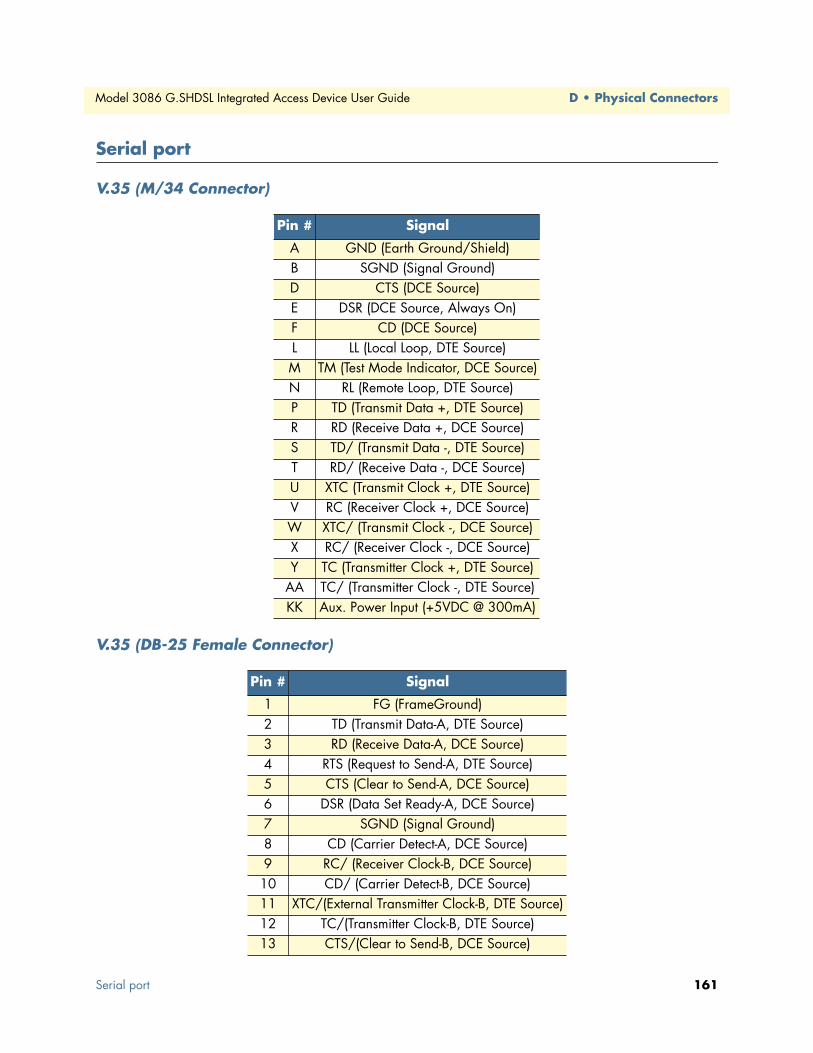
Model 3086 G.SHDSL Integrated Access Device User Guide D • Physical Connectors
Serial port
V.35 (M/34 Connector)
V.35 (DB-25 Female Connector)
Pin # Signal
A GND (Earth Ground/Shield)B SGND (Signal Ground)D CTS (DCE Source)E DSR (DCE Source, Always On)F CD (DCE Source)L LL (Local Loop, DTE Source)M TM (Test Mode Indicator, DCE Source)N RL (Remote Loop, DTE Source)P TD (Transmit Data +, DTE Source)R RD (Receive Data +, DCE Source)S TD/ (Transmit Data -, DTE Source)T RD/ (Receive Data -, DCE Source)U XTC (Transmit Clock +, DTE Source)V RC (Receiver Clock +, DCE Source)W XTC/ (Transmit Clock -, DCE Source)X RC/ (Receiver Clock -, DCE Source)Y TC (Transmitter Clock +, DTE Source)
AA TC/ (Transmitter Clock -, DTE Source)KK Aux. Power Input (+5VDC @ 300mA)
Pin # Signal
1 FG (FrameGround)2 TD (Transmit Data-A, DTE Source)3 RD (Receive Data-A, DCE Source)4 RTS (Request to Send-A, DTE Source)5 CTS (Clear to Send-A, DCE Source)6 DSR (Data Set Ready-A, DCE Source)7 SGND (Signal Ground)8 CD (Carrier Detect-A, DCE Source)9 RC/ (Receiver Clock-B, DCE Source)
10 CD/ (Carrier Detect-B, DCE Source)11 XTC/(External Transmitter Clock-B, DTE Source)12 TC/(Transmitter Clock-B, DTE Source)13 CTS/(Clear to Send-B, DCE Source)
Serial port 161

D • Physical Connectors Model 3086 G.SHDSL Integrated Access Device User Guide
X.21 (DB-15 Connector)
E1/T1 (RJ-48C Connector)
Power inputIEC 320 connector (two prong).
14 TD/(Transmit Data-A, DTE Source)15 TC(Transmitter Clock-B, DCE Source)16 RD (Receive Data-A, DCE Source)17 RC (Receiver Clock-A, DCE Source)18 LL (Local LIne Loop)19 RTS/(Request to Send-B, DTE Source)20 DTR (Data Terminal Ready-A, DTE Source)21 RL (Remote Loopback)22 DSR/ (Data Set Ready-B, DCE Source)23 DTR/(Data Terminal Ready-B, DTE Source)24 XTC (External Transmitter Clock-A, DTE Source)25 TM (Test Mode)
Pin # Signal
162 Power input

Appendix E Command Line Interface (CLI) Operation
Chapter contentsIntroduction ........................................................................................................................................................164CLI Terminology ................................................................................................................................................164
Local (VT-100 emulation) ............................................................................................................................164
Remote (Telnet) ............................................................................................................................................164Using the Console .........................................................................................................................................165
Administering user accounts ................................................................................................................................166
Adding new users ..........................................................................................................................................166Setting user passwords ...................................................................................................................................166Changing user settings ..................................................................................................................................167
Controlling login access ...........................................................................................................................167Controlling user access ............................................................................................................................167
G.SHDSL Commands: .................................................................................................................................167To establish the DSL link ........................................................................................................................168
163

E • Command Line Interface (CLI) Operation Model 3086 G.SHDSL Integrated Access Device User Guide
IntroductionThe modem configuration and status can also be view and modified through the console, which is accessible through the RS-232 serial port or through a Telnet session over Ethernet.
CLI TerminologyIn order to use the CLI commands, you need to understand the following CLI terms:
• Transport: A transport is a layer 2 session and everything below it. You can create a transport and attach it to a bridge or router so that data can be bridged or routed via the attached transport. The CLI supports the following transports:
• PPPoA: Point-to-Point Protocol over ATM
• PPPoE: Point-to-Point Protocol over Ethernet
• Frame Relay
• RFC1483
• IPoA: IP over ATM
• PPPoH: Point-to-Point over HDLC
• Ethernet
• Interface: bridges and routers both have interfaces. A single transport is attached to a bridge or router via an interface.
• Object: an object is anything that you can create and manipulate as a single entity, for example, interfaces, transports, static routes and NAT rules.
• List: Objects are numbered entries in a list. For example, if you have created more than one ethernet trans-port, the following command:
ethernet list transports
produces a list of numbered transport objects:
ID Name Port
1 eth2 ethernet
2 eth1 ethernet
Local (VT-100 emulation)A connection is made with the DB9-RJ45 adapter and an RJ45-RJ45 straight-through cable. Set the data rate to 9,600 baud, 8 data bits, one stop bits, and no parity. You may use a dumb terminal or a VT-100 emulation such as HyperTerminal.
Remote (Telnet)Establishing a Telnet session displays the same CLI configuration and status parameters on the display.
164 Introduction
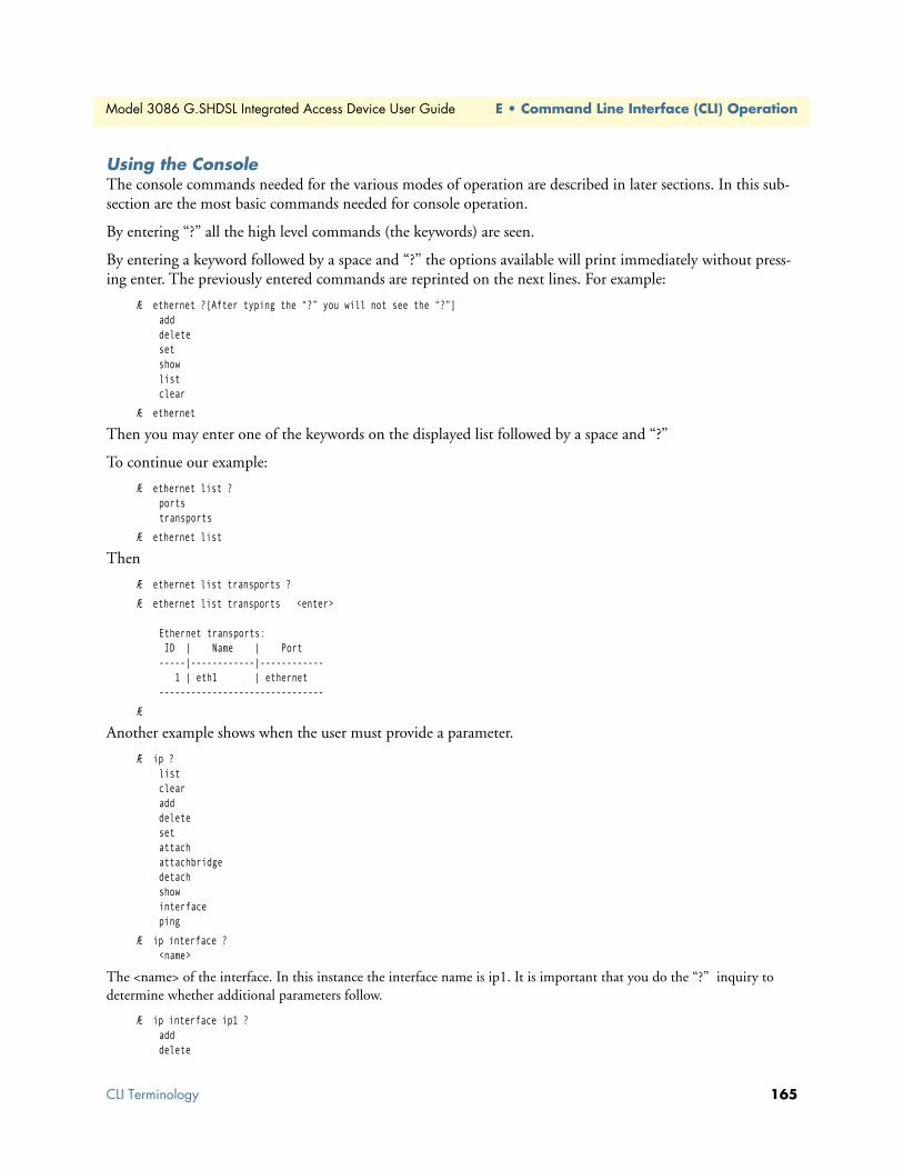
Model 3086 G.SHDSL Integrated Access Device User Guide E • Command Line Interface (CLI) Operation
Using the ConsoleThe console commands needed for the various modes of operation are described in later sections. In this sub-section are the most basic commands needed for console operation.
By entering “?” all the high level commands (the keywords) are seen.
By entering a keyword followed by a space and “?” the options available will print immediately without press-ing enter. The previously entered commands are reprinted on the next lines. For example:
Æ ethernet ?[After typing the “?” you will not see the “?”]adddeletesetshowlistclear
Æ ethernet
Then you may enter one of the keywords on the displayed list followed by a space and “?”
To continue our example:
Æ ethernet list ?portstransports
Æ ethernet list
Then
Æ ethernet list transports ?
Æ ethernet list transports <enter>
Ethernet transports: ID | Name | Port-----|------------|------------ 1 | eth1 | ethernet-------------------------------
Æ
Another example shows when the user must provide a parameter.
Æ ip ?listclearadddeletesetattachattachbridgedetachshowinterfaceping
Æ ip interface ?<name>
The <name> of the interface. In this instance the interface name is ip1. It is important that you do the “?” inquiry to determine whether additional parameters follow.
Æ ip interface ip1 ? adddelete
CLI Terminology 165

E • Command Line Interface (CLI) Operation Model 3086 G.SHDSL Integrated Access Device User Guide
clearlist
Æ ip interface ip1 list ?secondaryipaddresses
Æ ip interface ip1 list secondaryipaddresses ?
ip interface ip1 list secondaryipaddresses <enter>
Secondary IP addresses for interface: ip1 ID | IP Address-----|----------------------------------------
In this example there was not a secondary IP address. Now save the entire configuration in nonvolatile FLASH mem-ory with the following command.
Æ system config save
Wait for the message that says “Configuration Saved”, then reboot the modem with this command.
Æ system restart
Administering user accountsAs admin user you can administer user accounts. This section summarizes the CLI commands which can be used to administer user accounts.
Adding new usersTo add a new user username, use the command: system add user < username > <“Comment”>
system add login user < username > <“Comment”>
The first command creates a user who can access the system via a dialin connection using PPP for example. The second command creates a user who can login to the system.
For example, the commands:
system add user fred “user with dialin access”
system add login joe “user with login access”
creates two new users called fred and joe. The accounts are created with no passwords. To view details about the new users, enter:
system list users
The following information is returned:
Users:May May Access ID | Name | Conf. | Dialin | Level | Comment-----|--------|----------|----------|-----------|------------------------- 1 | fred | disabled | ENABLED | default | user with dialin access 2 | joe | ENABLED | disabled | default | user with login access 3 | admin | ENABLED | disabled | superuser | Default admin user--------------------------------------------------------------------------
Setting user passwordsTo change the password for the user you are currently logged in as, use the command:
user password
166 Administering user accounts

Model 3086 G.SHDSL Integrated Access Device User Guide E • Command Line Interface (CLI) Operation
Enter the new password twice as prompted:
Enter new password: ***Again to verify: ***→
Note No check is made for any current password which may have been set for the user.
If you wish to change the password for another user, enter the command:
user change <username>
This command logs you into the system as another user. You can then use the user password command to change the password for this user.
Note Changing to another user means that you lose all superuser privileges.
Note Only superusers can use the user change command.
Changing user settingsTo change any of the default settings for a user, use the following commands. For example, to change the set-tings for user fred:
system set user fred access {default|engineer|superuser}system set user fred maydialin {enabled|disabled}system set user fred mayconfigure {enabled|disabled}
For example, to change the security level for fred, enter:
system set user fred access engineer
Note Only superusers can use the user change command.
Controlling login accessTo set user login access for user username, use the command (all on one line):
system set login < username > access {default|engineer|superuser}
Controlling user accessTo set user access for user username, use the command (all on one line):
system set user < username > access {default|engineer|superuser}
G.SHDSL Commands:Command format: ‘gshdsl Action Attribute Value’
• Action – Two types of actions are available: ‘set’ or ‘show’
• Set – set attributes with a value.
• Show – get information from the box
• Attribute – The name of the attributes to access.
• Value – The new value for the attribute (Set command only)
Administering user accounts 167

E • Command Line Interface (CLI) Operation Model 3086 G.SHDSL Integrated Access Device User Guide
Example: To read the attribute ‘Version’: gshdsl show Version
To set data rate to 256K (4 * 64K): gshdsl set DSLRateTS
To set terminal type to CPE mode: gshdsl set terminal remote
To show the current terminal type: gshdsl show terminal
To establish the DSL link 1. One unit needs to be set to CO (central) and the other unit as CP (remote)
2. The Data rate of the 2 units have to be the same (DatarateN)
3. The interface type needs to be the same to pass data (Interface)
4. Issue the ‘Action’ command to start the handshaking process (Action Start)
Example: To set up the units to run at 2.048Mbps using ATM interface.
For CO (central) unit
→ gshdsl set terminal central
→ gshdsl set interface utopia
→ gshdsl set dataRateN 32
→ gshdsl set dataRateI 0
→ gshdsl set Action Start
For CPE (remote) unit
→ gshdsl set terminal remote
→ gshdsl set interface utopia
→ gshdsl set dataRateN 32
→ gshdsl set dataRateI 0
→ gshdsl set Action Start
Attribute Type Value Description
Version RO - The version number of the DSL driver
Platform RO - The platform name of the unit e.g. 3086 or 3086
ModemState RO IdleDeactivatedNorm OperIn-Progress
Show the state of the handshaking process:Idle – The DSL chip is in idle stateDeactivated – The DSL chip is deactivatedNormal Operation – The DSL chip is in operating (Link established)In-Progress – Handshaking in process
DSLRateTS RW 3-36 Data rate N number N=3-36. e.g. 256K data rate is N=4. The composite data rate is the cho-sen number N times 64 kbps. E.g., 32 x 64 kbps = 2.048 Mbps.
DataRateI RW 0-7 This attribute controls the size of the overhead channel. Valid input is 0-7. Default value is 0. (!!Keep it as 0)
terminal RW CentralRemote
Central – CO unitRemote – CPE unit
Interface RW Hdlc Utopia – Data will be packaged in ATM cell format and send through the UTOPIA interface of the processorHdlc – Data will be packaged in HDLC frame and send through the PCM Bus
Action WO StartDeactivate
Start – Command the box to configure the DSL chip and start the handshaking processDeactivate – Command the box to disconnect and deactivate the DSL link.
168 Administering user accounts

Model 3086 G.SHDSL Integrated Access Device User Guide E • Command Line Interface (CLI) Operation
Default Setting of the unit
Terminal: Remote
Interface: Hdlc
DataRateN: 24
DataRateI: 0
Administering user accounts 169

E • Command Line Interface (CLI) Operation Model 3086 G.SHDSL Integrated Access Device User Guide
170 Administering user accounts

Appendix F Interworking Functions Information
Chapter contentsIntroduction ........................................................................................................................................................173
Frame Relay Local Management Interface ...........................................................................................................173LMI Configuration Options: ........................................................................................................................173
managementType: (Default Value: no_maintenance) ..............................................................................173MgtState .................................................................................................................................................174
mgtAutoStart: (Default Value: FALSE) ...................................................................................................174T391_Value: (Default Value: 10) ............................................................................................................174T392_Value: (Default Value: 16) ............................................................................................................174
fullReportCycle: (Default Value: 6) .........................................................................................................174netErrorWindowSize: (Default Value: 4) ................................................................................................174netMaxErrors: (Default Value: 3) ............................................................................................................174userErrorWindowSize: (Default Value: 4) ...............................................................................................174userMaxErrors: (Default Value: 3) ...........................................................................................................174
CLI Configuration Methods .........................................................................................................................175Show current configuration .....................................................................................................................175Set configuration variable ........................................................................................................................175
Web Configuration Methods ........................................................................................................................176Frame Relay Service Interworking (FRF.8) ..........................................................................................................176
FRS Configuration Options ..........................................................................................................................176DE Mapping ...........................................................................................................................................176FECN Mapping ......................................................................................................................................177Translation Mode: ..................................................................................................................................177FRS Name ..............................................................................................................................................178
CLI Configuration Method ..........................................................................................................................179
Show one of the eight groups ..................................................................................................................179Set variable attributes on a specified group ..............................................................................................179Set variable attributes on a specified channel ...........................................................................................180
Web Configuration Methods ........................................................................................................................180FRS Overview Screen ..............................................................................................................................180Group/Channel Level Configuration Screen ...........................................................................................181
Frame Relay Network Interworking (FRF.5) .......................................................................................................182FRN Configuration Options .........................................................................................................................182
Port Level Configuration Options: ..........................................................................................................183
Channel Level Configuration Options ..........................................................................................................184CLI Configuration Methods for Port Level Management .............................................................................185
List all ports available to the system .........................................................................................................185
Show detailed information about a specific port ......................................................................................185Set configuration variables associated with the specified port ...................................................................186Configuration Management of the Channel Level Variables ....................................................................186
171
F • Interworking Functions Information Model 3086 G.SHDSL Integrated Access Device User Guide
Understanding the Channel Level View ..................................................................................................186Set Configuration Variables associated with the Channels .......................................................................187
Web Configuration Methods for FRF.5 Port and Channel Level Configuration ...........................................187Port Level Information Screen .................................................................................................................188Channel Level Information Screen ..........................................................................................................189Packet Information Screen ......................................................................................................................189
Frame Relay (Ethernet Based) Operations ...........................................................................................................190Frame Relay Configuration Options .............................................................................................................190
Channel Segment Size .............................................................................................................................190DLCI: Data Link Connection Identifier .................................................................................................190Encapsulation Type .................................................................................................................................190Port .........................................................................................................................................................190Rxmaxpdu ...............................................................................................................................................190Txmaxpdu ...............................................................................................................................................190
Frame Relay CLI Configuration Options ......................................................................................................190Build a new Frame Relay Transport ........................................................................................................190Clear all Frame Relay Transports .............................................................................................................191Delete the specified transport ..................................................................................................................191List all active Frame Relay Channels ........................................................................................................191Set configuration variables for the specified frame relay transport ............................................................191Show detailed configuration information on the specified channel: .........................................................191
Web Based Configuration of the Frame Relay Channel ................................................................................192Serial Interface Configuration..............................................................................................................................192
Configuration Variables Available .................................................................................................................192Clock Mode ............................................................................................................................................192Clock Invert Functions: (rxClkInv – receive clock, txClkInv – transmit clock) ........................................192Speed ......................................................................................................................................................192
CLI Configuration Methods .........................................................................................................................193Set configuration variable ........................................................................................................................193
Show current configuration settings ........................................................................................................193Gain help about the Serial Interface ........................................................................................................193
Web Interface Configurations .......................................................................................................................194Ping and Trace Route..........................................................................................................................................194
Ping commands from the CLI Interface ........................................................................................................194Trace Route from the CLI Interface ..............................................................................................................195
Define Usage: “ip traceroute” ..................................................................................................................195Start Trace Route: “ip traceroute start 192.168.50.2” ..............................................................................195
Ping and traceroute from the web interface: ..................................................................................................196Backup and Restore Features ...............................................................................................................................196
Backup Configuration ...................................................................................................................................196Restore Configuration ...................................................................................................................................196
172
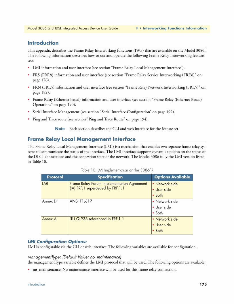
Model 3086 G.SHDSL Integrated Access Device User Guide F • Interworking Functions Information
IntroductionThis appendix describes the Frame Relay Interworking functions (IWF) that are available on the Model 3086. The following information describes how to use and operate the following Frame Relay Interworking feature sets:
• LMI information and user interface (see section “Frame Relay Local Management Interface”).
• FRS (FRF.8) information and user interface (see section “Frame Relay Service Interworking (FRF.8)” on page 176).
• FRN (FRF.5) information and user interface (see section “Frame Relay Network Interworking (FRF.5)” on page 182).
• Frame Relay (Ethernet based) information and user interface (see section “Frame Relay (Ethernet Based) Operations” on page 190).
• Serial Interface Management (see section “Serial Interface Configuration” on page 192).
• Ping and Trace route (see section “Ping and Trace Route” on page 194).
Note Each section describes the CLI and web interface for the feature set.
Frame Relay Local Management InterfaceThe Frame Relay Local Management Interface (LMI) is a mechanism that enables two separate frame relay sys-tems to communicate the status of the interface. The LMI interface supports dynamic updates on the status of the DLCI connections and the congestion state of the network. The Model 3086 fully the LMI version listed in Table 10.
LMI Configuration Options:LMI is configurable via the CLI or web interface. The following variables are available for configuration.
managementType: (Default Value: no_maintenance)the managementType variable defines the LMI protocol that will be used. The following options are available.
• no_maintenance: No maintenance interface will be used for this frame relay connection.
Table 10. LMI Implementation on the 3086FR
Protocol Specification Options Available
LMI Frame Relay Forum Implementation Agreement (IA) FRF.1 superceded by FRF.1.1
• Network side• User side• Both
Annex D ANSI T1.617 • Network side• User side• Both
Annex A ITU Q.933 referenced in FRF.1.1 • Network side• User side• Both
Introduction 173

F • Interworking Functions Information Model 3086 G.SHDSL Integrated Access Device User Guide
• 933A_Network: The ITU Q.933 protocol will be used. The unit will operate as the Network side of the connection
• 933A_User: The ITU Q.933 protocol will be used. The unit will operate as the User side of the connection
• 933A_Both: The ITU Q.933 protocol will be used. The unit will operate as both the Network and User side of the connection.
• 617D_Network: The ANSI T1.617 protocol will be used. The unit will operate as the Network side of the connection
• 617D_User: The ANSI T1.617 protocol will be used. The unit will operate as the User side of the connection
• 617D_Both: The ANSI T1.617 protocol will be used. The unit will operate as both the Network and User side of the connection.
MgtStateDefines the current state of the DTE side LMI. Possible options are as follows:
• Mgt_Port_DOWN: Currently the LMI on the DTE side is DOWN
• Mgt_Port_UP: Currently the LMI on the DTE side is UP
mgtAutoStart: (Default Value: FALSE)The management Auto Start variable allows the user to start the LMI session before any DLCI connections are created within the unit. If this variable is set to FALSE, the LMI session will begin when the first DLCI channel is created. If this variable is set to TRUE the LMI session will begin immediately.
T391_Value: (Default Value: 10)This variable sets the T391 timers in seconds.
T392_Value: (Default Value: 16)This variable sets the T392 timers in seconds.
fullReportCycle: (Default Value: 6)This variable represents the N391 protocol value
netErrorWindowSize: (Default Value: 4)Network side N393 protocol value
netMaxErrors: (Default Value: 3)Network side N392 protocol value
userErrorWindowSize: (Default Value: 4)User side N393 protocol value
userMaxErrors: (Default Value: 3)Network side N392 protocol value
174 Frame Relay Local Management Interface

Model 3086 G.SHDSL Integrated Access Device User Guide F • Interworking Functions Information
CLI Configuration MethodsThe following describes how to configure the LMI using the CLI. All LMI commands are contained under the “lmi” directive of the CLI interface. The following options are available:
Show current configurationCommand: “lmi show”
→ lmi show
FR_Mgt Type : no_maintenance
FR_Mgt State : Mgt_Port_DOWN
Full Report Cycle : 6
User Max Errors : 3
Net Max Errors : 3
User Error Window Size : 4
Net Error Window Size : 4
T391_Value : 10
T392_Value : 16
Mgt Auto Start : false
Set configuration variableCommand: “lmi set <variable> <value>”
Variable: Any variable from the above list <<<<<<< WHAT LIST??
Value: Value as defined by the variable
→ lmi set managementType 933A_Network
Frame Relay Local Management Interface 175

F • Interworking Functions Information Model 3086 G.SHDSL Integrated Access Device User Guide
Web Configuration Methods The following describes how to configure the LMI using the web interface. All LMI configuration variables are contained under the “LMI Management” window found through the IWF link. The following image shows the configuration variables available.
Frame Relay Service Interworking (FRF.8)FRF.8 is a conversion mechanism by which Frame Relay networks can communicate directly with ATM-based networks. Neither the ATM nor the Frame Relay networks require any understanding of the other network protocols involved. This conversion is performed within the Model 3086’s IWF at the transport service level. Frame Relay Service Interworking functions are defined by the Frame Relay Forum specification “Frame Relay/ATM PVC Service Interworking Implementation Agreement FRF.8.1”.
FRS Configuration OptionsThe Model 3086 supports 64 FRF.8 connections (divided into eight groups of eight channels each). The IWF are configured by group and channel. The group level configuration options are applied to eight channels that are related to that group. The following list of variables are configured at the group level.
DE MappingThe DE Mapping variable is used to determine how the Frame Relay DE field (Discard Eligibility) will be mapped to the ATM CLPI (Cell Loss Priority Indication) and vise versa. The following options are available:
• Always_zero:
– Frame Relay: All Frame Relay packets will have the DE field in the header set to a constant value of 0.
– ATM: All ATM cells will have the CLPI field set to a constant value of 0.
176 Frame Relay Service Interworking (FRF.8)

Model 3086 G.SHDSL Integrated Access Device User Guide F • Interworking Functions Information
• Always_one:
– Frame Relay: All Frame Relay packets will have the DE field in the header set to a constant value of 1.
– ATM: All ATM cells will have the CLPI field set to a constant value of 1.
• Convert:
– Frame Relay to ATM Direction: The system will convert the DE field received from the Frame Relay packet into the CLPI field of the outgoing ATM cell.
– ATM to Frame Relay Direction: The system will convert the CLPI bit received from the ATM cells into the DE field of the outgoing Frame Relay packet.
FECN MappingThe FECN Mapping variable is used to determine how the Frame Relay FECN (Forward Explicit Congestion Notification) bit will be mapped to the ATM EFCI (Explicit Forward Congestion Indication) bit and vise versa. The following options are available:
• Always_zero:
– Frame Relay: All Frame Relay packets will have the FECN bit in the header set to a constant value of 0.
– ATM: All ATM cells will have the EFCI bit set to a constant value of 0.
• Always_one:
– Frame Relay: All Frame Relay packets will have the FECN bit in the header set to a constant value of 1.
– ATM: All ATM cells will have the EFCI bit set to a constant value of 1.
• Convert:
– Frame Relay to ATM Direction: The system will convert the FECN bit received from the Frame Relay packet into the EFCI bit of the outgoing ATM cell.
– ATM to Frame Relay Direction: The system will convert the EFCI bit received from the ATM cells into the FECN bit of the outgoing Frame Relay packet.
Translation Mode:The Translation Mode variable defines the encapsulation mechanism that will be required to convert the ATM cells (encapsulated per RFC1483) to the Frame Relay packets (encapsulated per RFC1490) and back. This is required because ATM and Frame Relay encapsulate packets in different formats as defined by their respective RFC. There are two options available for the Translation Mode setting within the Model 3086 as defined below:
• Translate: When the connection channel is set to translate, the IWF converts between Frame Relay encap-sulated packets and the ATM encapsulated cells. This conversion is performed by inspecting each packet/cell and determining the PID (Protocol Identification) field within the packet. Using this information, the packet/cell is routed through an encapsulation conversion utility that creates the encapsulation required for the destination network. The Model 3086 supports all 22 encapsulation types as defined by the FRF.8.1
Frame Relay Service Interworking (FRF.8) 177

F • Interworking Functions Information Model 3086 G.SHDSL Integrated Access Device User Guide
specification. See figure 16 for the encapsulation types and includes an example where a Routed IP packet is received on both the Frame Relay and ATM sides of the connection. When the packet is received is checked against the known PID fields, and then the packet is routed to the appropriate encapsulation conversion station before being sent out the opposite interface.
Figure 16. FRS encapsulation conversion using Translate Mode
• Transparent: The second translation mode option is to set the protocol value to transparent. Transparent is used when the Protocol being used is not one of the 22 predefined encapsulation types, such as is the case for voice based systems. When the translation mode is set to transparent, the packet data will be transpar-ently passed from one network to the other without any encapsulation conversions.
FRS NameAllows the user to name the FRS channel. This is helpful when viewing multiple connections to determine which DLCI/VPI/VCI combination is associated with each channel.
• FRS state: The state variable allows the user to enable or disable the channel for operation.
178 Frame Relay Service Interworking (FRF.8)

Model 3086 G.SHDSL Integrated Access Device User Guide F • Interworking Functions Information
The Frame Relay Service Interworking functions on the Patton Electronics Model 3086FR are also defined as sixty-four channels. Each channel creates a connection between a single DLCI on the Frame Relay network and a VPI/VCI on the ATM network. The following configuration options are available for each channel in the system.
• VPI—Virtual Path Identifier: ATM side Virtual Path Identifier for the specified connection.
• VCI—Virtual Channel Identifier: ATM side Virtual Channel Identifier for the specified connection
• DLCI—Data Link Connection Identifier: Frame Relay side DLCI for the specified connection
CLI Configuration MethodThe following section describes how to configure FRS channel connections using the CLI interface.
The system is made up of eight groups and 64 channels. The group configuration variables apply to all eight channels within that group. Each channel is configured independently and will all run over as single LMI ses-sion or with no LMI running. The FRS (FRF.8) connections are configured using the “frs” directive in the CLI interface. The following commands are available:
Show one of the eight groupsCommand: frs show group #
The frs show group # command shows the configuration of te group defined by the # directive. Possible options are 1–8. The following shows an example setup:
→ frs show group 1
Group Level Information: Group A
Group Name:
Group DE Mapping: zero
Group Trans Mode: translate
Group FECN Mapping: zero
Channel Level Information: Channels 1 - 8
---------------------------------------------------------------------
|Chn |VPI |VCI |DLCI| Activate | Tx Pkt G/B | Rx Pkt G/B
|chn1 |100 |200 |172 |enable |0/0 |0/0
|chn2 |1 |101 |101 |disable |N/A |N/A
|chn3 |2 |102 |102 |disable |N/A |N/A
|chn4 |3 |103 |103 |disable |N/A |N/A
|chn5 |4 |104 |104 |disable |N/A |N/A
|chn6 |5 |105 |105 |disable |N/A |N/A
|chn7 |6 |106 |106 |disable |N/A |N/A
|chn8 |7 |107 |107 |disable |N/A |N/A
Set variable attributes on a specified groupCommand: frs set group # <variable> <value>
Note At any point during the typing of the command selecting the “?” will display the possible options available to the user.
Frame Relay Service Interworking (FRF.8) 179

F • Interworking Functions Information Model 3086 G.SHDSL Integrated Access Device User Guide
Note After the first several letters of the command are typed pressing the Tab key will tell the system to complete the variable or command name.
The frs set group command allows the user to setup the configuration of the group variables. The following example could be used to set the DEMapping variable to “convert”.
Note At the end of the first line the “?” was selected and the system prompted the user with the possible options available.
→ frs set group 1 DEMapping ?
convert
one
zero
→ frs set chn1 DEMapping convert
Set variable attributes on a specified channelCommand: frs set channel # <variable> <value>
The following example could be used to set the DLCI variable to 171.
→ frs set channel 1 DLCI 171
Web Configuration MethodsThe following documentation defines how to configure the FRS channel connections using the web interface on the x Model 3086. All web interface screens our found under the IWF link.
FRS Overview ScreenBy selecting the “FRS Setup (FRF.8)” link below the IWF heading will bring up an overview of the FRS con-nection available within the system. This page shows a top level view of the eight groups available. The
180 Frame Relay Service Interworking (FRF.8)

Model 3086 G.SHDSL Integrated Access Device User Guide F • Interworking Functions Information
“Group #” column along the left side of the screen is a hyperlink that will bring up detailed configuration information about each group and the channels available in the group.
Group/Channel Level Configuration ScreenBy selecting the “Group #” link in the FRS Overview screen, the detailed channel level information screen is displayed as shown below. This screen allows configuration of all variables associated with the group and chan-nels. The screen is broken down into three sections; the first section allows configuration of the group level information, the second section allows configuration of the channels associated with the group, the last screen shows the packet counters.
Figure 17. RF.8 Group Level Configuration window
Frame Relay Service Interworking (FRF.8) 181
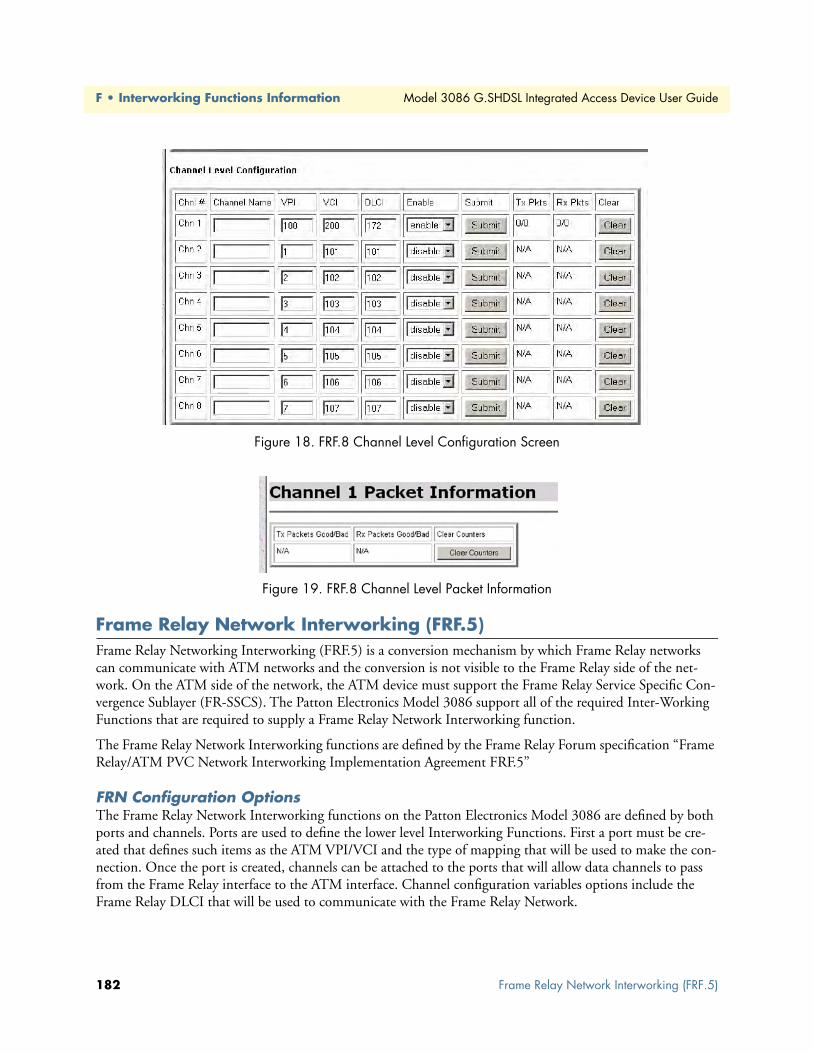
F • Interworking Functions Information Model 3086 G.SHDSL Integrated Access Device User Guide
Figure 18. FRF.8 Channel Level Configuration Screen
Figure 19. FRF.8 Channel Level Packet Information
Frame Relay Network Interworking (FRF.5)Frame Relay Networking Interworking (FRF.5) is a conversion mechanism by which Frame Relay networks can communicate with ATM networks and the conversion is not visible to the Frame Relay side of the net-work. On the ATM side of the network, the ATM device must support the Frame Relay Service Specific Con-vergence Sublayer (FR-SSCS). The Patton Electronics Model 3086 support all of the required Inter-Working Functions that are required to supply a Frame Relay Network Interworking function.
The Frame Relay Network Interworking functions are defined by the Frame Relay Forum specification “Frame Relay/ATM PVC Network Interworking Implementation Agreement FRF.5”
FRN Configuration OptionsThe Frame Relay Network Interworking functions on the Patton Electronics Model 3086 are defined by both ports and channels. Ports are used to define the lower level Interworking Functions. First a port must be cre-ated that defines such items as the ATM VPI/VCI and the type of mapping that will be used to make the con-nection. Once the port is created, channels can be attached to the ports that will allow data channels to pass from the Frame Relay interface to the ATM interface. Channel configuration variables options include the Frame Relay DLCI that will be used to communicate with the Frame Relay Network.
182 Frame Relay Network Interworking (FRF.5)

Model 3086 G.SHDSL Integrated Access Device User Guide F • Interworking Functions Information
Port Level Configuration Options:Ports are used to define the lower level Interworking Functions. The port configuration will define the follow-ing variables:
• VPI—Virtual Path Identifier: ATM side Virtual Path Identifier for the specified connection.
• VCI—Virtual Channel Identifier: ATM side Virtual Channel Identifier for the specified connection
• DE Mapping: The DE Mapping variable is used to determine how the Frame Relay DE field (Discard Eli-gibility) will be mapped to the ATM CLPI (Cell Loss Priority Indication). This variable is only used in the Frame Relay to ATM mapping direction. Note that the DE bit from the core Q.922 (Frame Relay) packet will always be copied unchanged into the FR-SSCS PDU header cell. The following options define how the DE will be mapped to the ATM CLPI bit:
– Always_zero: All ATM cells will have the CLPI field set to a constant value of 0.
– Always_one: ATM: All ATM cells will have the CLPI field set to a constant value of 1.
– Convert: The system will convert the DE field received from the Frame Relay packet into the CLPI field of the outgoing ATM cell that is generated by the segmentation process.
• CLPI Mapping: The CLPI Mapping variable is used to determine how the ATM CLPI (Cell Loss Priority Indication) bit in the ATM cell will be mapped to the DE (Discard Eligibility) bit of the resulting Frame Relay packet. There are two options available.
– Fr_sscs_only: The FR-SSCS removed from the ATM header PDU is used to set the DE bit in the out-put Frame Relay packet. The CLPI bit from the ATM cell is ignored.
– Fr_sscs_and_clpi: Both the DE bit from the ATM header PDU and the CLPI bit from the received ATM cells are used to determine the output state of the resulting Frame Relay packet. The following table defines how .
• Multiplexing Mode: The MuxMode variable allows multiple channels to be multiplexed onto a single port. A port is defined by its’ VPI/VCI of the ATM rfc1483 data path. Channels are defined by their Frame Relay DLCI. Thus, the multiplexing mode will allow multiple Frame Relay channels to be transported over a sin-gle ATM VPI/VCI link. There are two options available.
– Mux_many_to_one: The “many to one” option allows multiple DLCI channels to be transported over a single ATM rfc1483 connection. Note that if the MuxMode is not set to “many to one” trying to add multiple DLCI connections will result in errors.
– Mux_one_to_one: The “one to one” option notifies the system that there will be a one to one mapping between a single ATM port VPI/VCI and a single Frame Relay DLCI.
• FRN Name: Allows the user to name the FRN port. This is helpful when viewing multiple connections to determine which VPI/VCI is associated with each port.
CLPI received from ATM cell DE from FR-SSCS of ATM cell Outgoing DE bit of FR Packet
0 0 01 X 1X 1 1
Frame Relay Network Interworking (FRF.5) 183

F • Interworking Functions Information Model 3086 G.SHDSL Integrated Access Device User Guide
• FRS state: The state variable allows the user to enable or disable the port for operation. Note that port level configuration variables are not changeable “on the fly”. If it is required that configuration changes are required, the user should disable the port, make the configuration changes, and then re-enable the port.
• Port Level Maintenance: Port level maintenance creates an LMI session across the ATM link. This is useful to determine the status of the link. There are three options available for Port Level Maintenance. The description of these variables is identical to that described in the beginning of this document. Note that in each case the only option available is “both”. This means that the system is performing both “Network” and “User” side LMI functions.
– 933A_both
– 617D_both
– LMI_both
• Port Level Mgt State: This variable defines the state of the Port Level Maintenance.
– Mgt_Port_DOWN: Currently the LMI on the DTE side is DOWN
– Mgt_Port_UP: Currently the LMI on the DTE side is UP
Channel Level Configuration OptionsThe Channel Level Configuration variables are used to define the channels that are attached to the ATM port. The following variables are used to define each channel configuration.
• DLCI—Data Link Connection Identifier: Frame Relay side DLCI for the associated channel.
• FRN Channel Name: Allows the user to name the FRN channel. This is helpful when viewing multiple channel connections to determine which DLCI is associated with each channel.
• FRN Channel State: The state variable allows the user to enable or disable the channel for operation. Note that the port that the channel is connected to must be enabled before the channel can be enabled for opera-tion.
• Network DLCI: The network DLCI allows the system to transport data over the atm link using a different DLCI than is used on the DTE side. If the network DLCI is set to “0”, then the DTE side DLCI will be used. If the Network DLCI is set to any other value, that value will be used to transport data across the link using the FR-SSCS.
• Mgt State: The Mgt State variables defines the state of the Channel using the Port Level Management infor-mation. The following options are available
– N/A: The port associated with this channel is disabled.
– n/a: There is no Port Level Management function enabled for the port associated with this channel.
– Down: The Port Level Management is currently in the “down” state.
– active-congested: The Port Level Management is reporting that this channel is active and it has detected that the channel is congested.
– Active: The Port Level Management is reporting that this channel is active
– Deleted: The Port Level Management is reporting that this channel has been deleted. This could also result if the associated channel at the remote end is not configured
184 Frame Relay Network Interworking (FRF.5)

Model 3086 G.SHDSL Integrated Access Device User Guide F • Interworking Functions Information
– not active: No information has been received from the management port related to this channel
CLI Configuration Methods for Port Level ManagementThe following information can be used to configure the Port Level information associated with the FRN con-nections. The CLI uses the “frn” directive of the CLI interface for Port Level configuration.
List all ports available to the systemCommand: frn list
The “frn list” command will display the current high level state of each port available in the system. More information about each specific port can be gained by the “show port” command described below. The follow-ing shows the output of the “frn list” command.
→ frn list
----------------------------------------------------------------------
|Port | Name | VPI | VCI | DLCI | Activate | Mux Mode
|port1 | main | 0 | 100 | 100 | disable | mux_one_to_one |
|port2 | backup | 10 | 110 | 110 | disable | mux_one_to_one |
|port3 | none | 20 | 120 | 120 | disable | mux_one_to_one |
|port4 | none | 30 | 130 | 130 | disable | mux_one_to_one |
|port5 | none | 40 | 140 | 140 | disable | mux_one_to_one |
|port6 | none | 50 | 150 | 150 | disable | mux_one_to_one |
|port7 | none | 60 | 160 | 160 | disable | mux_one_to_one |
|port8 | none | 70 | 170 | 170 | disable | mux_one_to_one |
----------------------------------------------------------------------
Show detailed information about a specific portCommand: frn show port#
The “frn show port#” command will display detailed information about the port defined in the command. The following shows the actual output of the configuration of port 3. Note that the “frn show port” will also dis-play information about the channels that are associated with that port.
frn show port1 command output
Port Level Information: Port 1
FRN Port Name: none
FRN VPI: 0
FRN VCI: 100
FRN DE Mapping: zero
FRN CLPI Mapping: fr_sscs_only
FRN Mux Mode: mux_one_to_one
FRN Header Type: 2_byte
FRN DC Mapping: zero
FRN State: enable
FRN Core Name: FRN0
FRN Tx Packets: 146/1
Frame Relay Network Interworking (FRF.5) 185

F • Interworking Functions Information Model 3086 G.SHDSL Integrated Access Device User Guide
FRN Rx Packets: 145/0
FRN Network Mgt: lmi_both
FRN Net Mgt State: port_mgt_UP
Channel Level Information:
---------------------------------------------------------------------
|Chn1 |DLCI|Net DLCI|Activate| Tx Pkt G/B | Rx Pkt G/B |Status
|chn1 |100 |0 |enable | 0/0 | 0/0 |active
|chn2 |101 |0 |disable | N/A | N/A |N/A
|chn3 |102 |0 |disable | N/A | N/A |N/A
|chn4 |103 |0 |disable | N/A | N/A |N/A
|chn5 |104 |0 |disable | N/A | N/A |N/A
|chn6 |105 |0 |disable | N/A | N/A |N/A
|chn7 |106 |0 |disable | N/A | N/A |N/A
|chn8 |107 |0 |disable | N/A | N/A |N/A
-------------------------------------------------------------------
Set configuration variables associated with the specified portCommand: frn set port# <variable> <value>
The “frn set port#” command allows the user to set port level specific variables to their optional values. All vari-ables described above for the port level configurations are available from the “frn set port#” command screen. The following example shows the setting of port #5 MuxMode to mux_many_to_one. NOTE that after the first line the “?” was used to determine the possible configuration options available to the user.
Note At any point during the typing of the command selecting the “?” will display the possible options available to the user.
Note After the first several letters of the command are typed pressing the Tab key will tell the system to complete the variable or command name.
→ frn set port5 MuxMode
mux_many_to_one
mux_one_to_one
→ frn set port5 MuxMode mux_many_to_one
Configuration Management of the Channel Level VariablesThe following information can be used to configure the Channel Level information associated with the FRN connections. The CLI uses the “frn” directive of the CLI interface for Channel Level configuration. Note that the “frn show port” and “frn list” commands already discussed at the port level are also useful to gain detailed and overview information about the channels.
Understanding the Channel Level ViewThe Patton Electronics Model 3086 supports up to eight individual FRN Ports. Each port can support up to eight Channels while set to the “many to one” multiplexing mode. To access the port level information the user
186 Frame Relay Network Interworking (FRF.5)
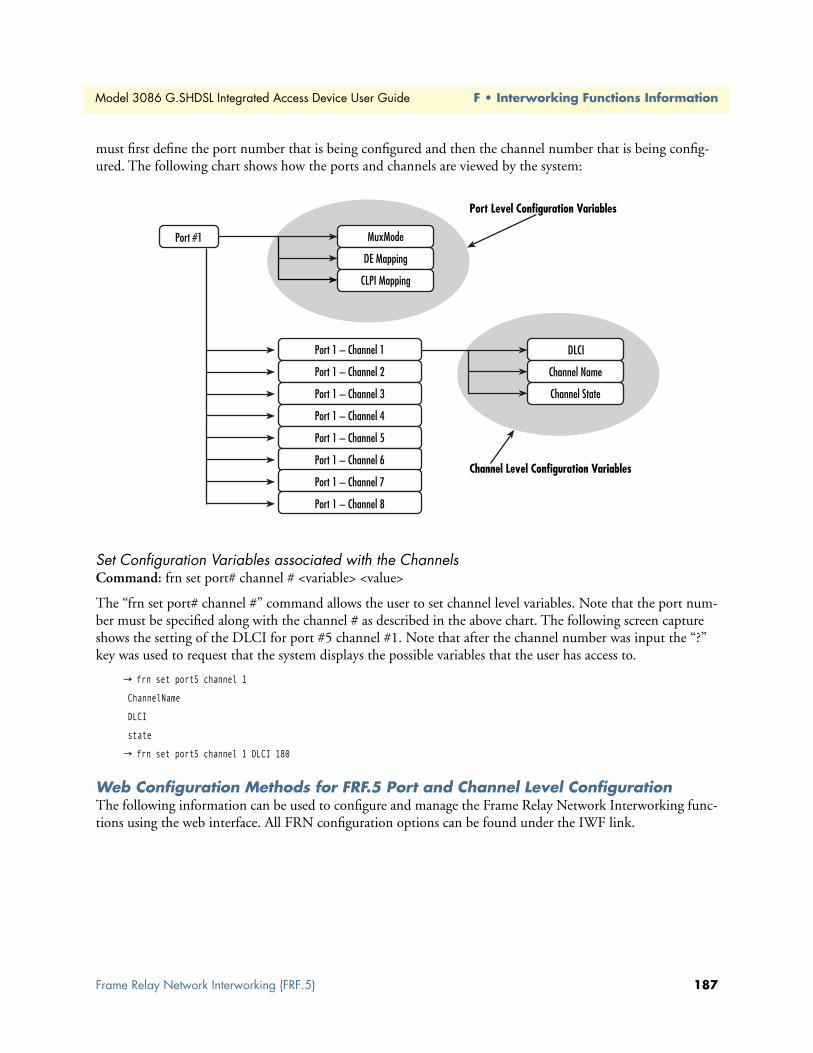
Model 3086 G.SHDSL Integrated Access Device User Guide F • Interworking Functions Information
must first define the port number that is being configured and then the channel number that is being config-ured. The following chart shows how the ports and channels are viewed by the system:
Set Configuration Variables associated with the Channels Command: frn set port# channel # <variable> <value>
The “frn set port# channel #” command allows the user to set channel level variables. Note that the port num-ber must be specified along with the channel # as described in the above chart. The following screen capture shows the setting of the DLCI for port #5 channel #1. Note that after the channel number was input the “?” key was used to request that the system displays the possible variables that the user has access to.
→ frn set port5 channel 1
ChannelName
DLCI
state
→ frn set port5 channel 1 DLCI 180
Web Configuration Methods for FRF.5 Port and Channel Level ConfigurationThe following information can be used to configure and manage the Frame Relay Network Interworking func-tions using the web interface. All FRN configuration options can be found under the IWF link.
Frame Relay Network Interworking (FRF.5) 187

F • Interworking Functions Information Model 3086 G.SHDSL Integrated Access Device User Guide
Once “FRN Setup (FRF.5)” is selected the Port Level Overview screen is displayed as shown below.
The screen gives an overview of the FRN connections that are available. Each Port Number in the left column is a hyperlink that will display a more detailed view of the port along with the configuration of the channel level information. This screen is broken down into three sections. Each section is shown below.
Port Level Information ScreenThe Port Level configuration information allows the user to configure Port Level variables. After configuration changes have been made, use the “Configure Port” button to set those parameters.
188 Frame Relay Network Interworking (FRF.5)

Model 3086 G.SHDSL Integrated Access Device User Guide F • Interworking Functions Information
Channel Level Information ScreenThe Channel Level configuration section of the screen allows the user to setup and configure the individual channels associated with the specified port. Note that in the screen show below only a single channel is avail-able for configuration. This is because the port, shown above, is set to a MuxMode of one to one.
Packet Information ScreenThe following screen capture shows the packet information that is available for each channel. Note that the direction of the data is referenced to the ATM link. Thus Tx Data is data that is received on the Frame Relay link and transmitted out the ATM Link.
Frame Relay Network Interworking (FRF.5) 189

F • Interworking Functions Information Model 3086 G.SHDSL Integrated Access Device User Guide
Frame Relay (Ethernet Based) OperationsEthernet based (or basic) Frame Relay is also available within the Patton Electronics Model 3086. This Frame Relay service can be used in a similar fashion to other Ethernet based transports within the system such as PPP or the Ethernet transport. Multiple Frame Relay transports, with different DLCI numbers, can be built upon the HDLC controller that is available with the 3086. The Frame Relay Interface is available at the Serial Inter-face for transport out of the Ethernet Interface or the ATM link.
Frame Relay Configuration OptionsThe Frame Relay transport is configurable from both the CLI and the web interface. The following config-urable variables are available through both interfaces.
Channel Segment SizeThe channel segment size is used to define fragmentation of the packets based on the Frame Relay Forum IA FRF.12. If this variable is set to 0 then FRF.12 “Frame Relay Fragmentation” will be disabled. If set to any other value it will set the fragmentation size used.
DLCI: Data Link Connection IdentifierThe Frame Relay DLCI used for the specified channel. Must be set to a non-zero number as agreed upon by the Frame Relay connection.
Encapsulation TypeDefines the FRC1490 encapsulation type that will be used by the channel.
PortDefines the port that should be used to setup the Frame Relay Connection. For routed applications the port should be set to “frf ”. For bridged applications the port should be set to “fr”.
RxmaxpduReceive side max PDU
TxmaxpduTransmit side max PDU
Frame Relay CLI Configuration OptionsThe following information describes how to configure the frame relay transport on the 3086 through the CLI interface.
Build a new Frame Relay TransportCommand: framerelay add transport <name> <port> <dlci>
Add a new frame relay transport to the system
• Name: Any name can be given to the transport. This name will be used to reference the transport in later commands.
190 Frame Relay (Ethernet Based) Operations

Model 3086 G.SHDSL Integrated Access Device User Guide F • Interworking Functions Information
• Port: This variable defines the low layer port that will be used to transport data across the frame relay inter-face. For routed application the “frf ” port should be used. For bridged applications the “fr” port should be used.
• DLCI: This variable can be set to any positive value less than 8196
Clear all Frame Relay TransportsCommand: framerelay clear transport
This command can be used to clear all of the transports in the system
Delete the specified transportCommand: framerelay delete transport <name | number>
Delete a single frame relay connection using either the connection name or number
• name: the name used when creating the transport
• number: the ID number found when listing the transports
List all active Frame Relay ChannelsCommand: framerelay list transports
List all transports currently defined in the system
Set configuration variables for the specified frame relay transportCommand: framerelay set transport <name | number> <variable> <value>
Set a value for a specific frame relay variable
1. name | number: specify the connection that you would like to change
2. variable: any variable from the above list
3. value: value that you would like to set
Show detailed configuration information on the specified channel: Command: framerelay show transport <name | number>
Display specific information about the frame relay connection
Frame Relay (Ethernet Based) Operations 191

F • Interworking Functions Information Model 3086 G.SHDSL Integrated Access Device User Guide
Web Based Configuration of the Frame Relay ChannelThis section defines the configuration of the Frame Relay Service through the web interface. The Frame Relay channel is created through the Configuration->WAN link.
Serial Interface ConfigurationThis section defines the configuration options available for the serial interface on the Model 3086. This infor-mation could be used to configure the V.35 or X.21 interface available on the unit.
Configuration Variables AvailableThe following variables are configurable through either the CLI or web interface on the unit.
Clock ModeDetermines the source of timing for the unit.
• Internal: The unit will generate the appropriate clock speed defined by the speed setting of the interface.
• External: The unit will accept the clock from the interface and will use that clock to receive and transmit data across the interface
Clock Invert Functions: (rxClkInv – receive clock, txClkInv – transmit clock)Setting this variable will invert the appropriate clock at the interface. This should only be used under direction of Patton Electronics technical support in order to trouble shoot system installations. Possible settings include both normal and inverted
SpeedThe speed setting function will determine the clock rate that will be used by the interface. Appropriate settings include any n x 64K speed setting between 64KHz – 2048KHz.
192 Serial Interface Configuration

Model 3086 G.SHDSL Integrated Access Device User Guide F • Interworking Functions Information
CLI Configuration MethodsThe following section defines how to configure the serial interface using the CLI. All serial interface functions are available under the “serial” directive of the CLI.
Set configuration variable Command: serial set <variable> <value>
The following shows the user setting the speed of the serial interface to a value of 2048MHz.
→ serial speed 2048
Show current configuration settingsCommand: serial show
The “serial show” command will tell the system to display the current configuration settings for the serial inter-face. The following shows the output of the “serial show” command.
→ serial show
Clock Source : internal
Intf Speed : 2048
Tx Sample Point : txclk
Tx Clk Inv : normal
Rx Clk Inv : normal
Gain help about the Serial InterfaceCommand: serial help
This command will request that the system provide help about each of the configuration variables that are available in the serial interface. The following shows the output of the “serial help” command.
→ serial help
Serial Interface Help Screen
>serial show: > Show the current configuration of the > serial interface >serial help: > Show this help screen >serial clock: > Defines the clock mode or source of timing > for the serial interface. > options: internal - internal timing > external - external timing > notes: For X.21 devices this setting must match > the DTE/DCE jumper inside the unit >serial speed: > Defines the clock speed for the serial interface > options: n x 64K speed (n= 1..32), example: "1536" or "256" > > serial txClkInv: > Allows the user to invert the clock source > options: normal - use normal clock > inverted - use the inverted version of the clock
Serial Interface Configuration 193

F • Interworking Functions Information Model 3086 G.SHDSL Integrated Access Device User Guide
> serial rxClkInv: > Allows the user to invert the clock source > options: normal - use normal clock > inverted - use the inverted version of the clock > serial txSamplePoint: > Determines whether the TxData will use the External > Clock or the Transmit clock to sample data > options: txClk - use Transmit Clock > extClk - use External Clock >
Web Interface ConfigurationsThe serial interface can be configured using the web interface by following the “Serial” hyperlink on the web management screen. The following screen shot shows the configuration variables as they are displayed on the web management screen.
Ping and Trace RouteThe ping and trace route features are now available from both the web and CLI of the Patton Electronics’ Model 3086. The following sections describe how to operate both the ping and trace route features from the CLI and web interface.
Ping commands from the CLI InterfaceThe ping command can be initiated from the CLI interface using the “ip” directive. The following screen shot show a ping sent and successfully received on the Ethernet interface. Then following shows an unsuccessful ping to the Ethernet interface.
→ ip ping 192.168.50.2
ping: PING 192.168.50.2: 32 data bytes
ping: 40 bytes from 192.168.50.2: seq=0, ttl=255, rtt=10ms
→ ip ping 192.168.50.21
ping: PING 192.168.50.21: 32 data bytes
ping: Request timed out.
194 Ping and Trace Route
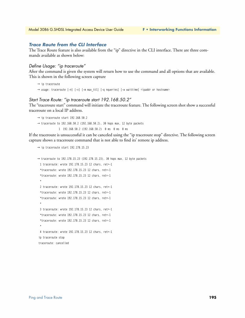
Model 3086 G.SHDSL Integrated Access Device User Guide F • Interworking Functions Information
Trace Route from the CLI InterfaceThe Trace Route feature is also available from the “ip” directive in the CLI interface. There are three com-mands available as shown below:
Define Usage: “ip traceroute”After the command is given the system will return how to use the command and all options that are available. This is shown in the following screen capture
→ ip traceroute
→ usage: traceroute [-n] [-v] [-m max_ttl] [-q nqueries] [-w waittime] <ipaddr or hostname>
Start Trace Route: “ip traceroute start 192.168.50.2”The “traceroute start” command will initiate the traceroute feature. The following screen shot show a successful traceroute on a local IP address.
→ ip traceroute start 192.168.50.2
→ traceroute to 192.168.50.2 (192.168.50.2), 30 hops max, 12 byte packets
1 192.168.50.2 (192.168.50.2) 0 ms 0 ms 0 ms
If the traceroute is unsuccessful it can be canceled using the “ip traceroute stop” directive. The following screen capture shows a traceroute command that is not able to find its’ remote ip address.
→ ip traceroute start 192.178.15.23
→ traceroute to 192.178.15.23 (192.178.15.23), 30 hops max, 12 byte packets
1 traceroute: wrote 192.178.15.23 12 chars, ret=-1
*traceroute: wrote 192.178.15.23 12 chars, ret=-1
*traceroute: wrote 192.178.15.23 12 chars, ret=-1
*
2 traceroute: wrote 192.178.15.23 12 chars, ret=-1
*traceroute: wrote 192.178.15.23 12 chars, ret=-1
*traceroute: wrote 192.178.15.23 12 chars, ret=-1
*
3 traceroute: wrote 192.178.15.23 12 chars, ret=-1
*traceroute: wrote 192.178.15.23 12 chars, ret=-1
*traceroute: wrote 192.178.15.23 12 chars, ret=-1
*
4 traceroute: wrote 192.178.15.23 12 chars, ret=-1
ip traceroute stop
traceroute: cancelled
Ping and Trace Route 195

F • Interworking Functions Information Model 3086 G.SHDSL Integrated Access Device User Guide
Ping and traceroute from the web interface:Both the Ping and Traceroute features are available from the web interface on the Model 3086. The following screen capture show the output of a ping command that was initiated. The ping and traceroute commands can be found by following the “System” link and then the “Ping” link.
Backup and Restore FeaturesThe backup and restore feature allows the user to store the current configuration off line on a local PC for later retrieval by the system. This feature can be found on the web under the “System” link. The following screen capture shows the “backup and restore” web page.
Backup ConfigurationTo backup the configuration of the unit select the “Backup” button on the configuration page. You will be prompted to save the file on the local PC. Once the file has been downloaded it is available to be restored at a later date.
Restore ConfigurationTo restore the configuration either type the file location or name in the box provided or select the “Browse” button on the screen. Once the file is found select the “Restore” button on the configuration page. When the configuration is loaded it will automatically set the uploaded file as the running configuration. If the configura-tion is required for future setup, save the configuration in the unit.
196 Backup and Restore Features


