Model 266DDH Differential Model 266HDH Gauge 2600T … · Model 266DDH Differential Model 266HDH...
76
Model 266DDH Differential Model 266HDH Gauge Model 266NDH Absolute Data Sheet DS/266XDH-EN Base accuracy – from 0.06 % of calibrated span Reliable sensing system coupled with very latest digital technologies – provides large turn down ratio up to 60:1 Comprehensive sensor choice – optimize in-use total performance and stability Flexible configuration facilities – provided locally via local LCD keypad 2600T Series Pressure Transmitters Engineered solutions for all applications New TTG (Through-The-Glass) keypad technology – allows quick and easy local configuration without opening the cover, even in explosion proof environments IEC 61508 certification – for SIL2 (1oo1) and SIL3 (1oo2) applications PED compliance to sound engineering practice (SEP)
Transcript of Model 266DDH Differential Model 266HDH Gauge 2600T … · Model 266DDH Differential Model 266HDH...

Model 266DDH Differential Model 266HDH Gauge Model 266NDH Absolute
Data Sheet DS/266XDH-EN
Base accuracy – from 0.06 % of calibrated span
Reliable sensing system coupled with very latest digital technologies– provides large turn down ratio up to 60:1
Comprehensive sensor choice– optimize in-use total performance and stability
Flexible configuration facilities– provided locally via local LCD keypad
2600T Series Pressure TransmittersEngineered solutions for allapplications
New TTG (Through-The-Glass) keypad technology– allows quick and easy local configuration without opening the cover, even in explosion proof environments
IEC 61508 certification – for SIL2 (1oo1) and SIL3 (1oo2) applications
PED compliance to sound engineering practice (SEP)
2 DS/266XDH-EN | 2600T Series Pressure transmitters 266DDH, 266HDH, 266NDH
Model 266DDH Differential Model 266HDH Gauge Model 266NDH Absolute
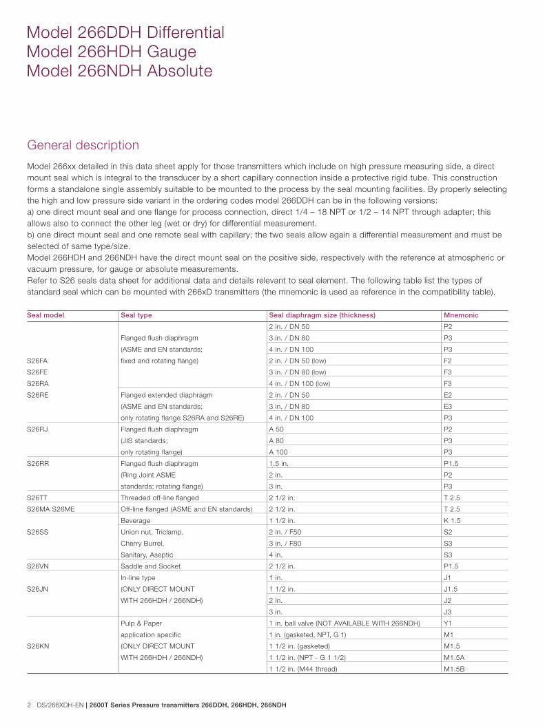
Seal model Seal type Seal diaphragm size (thickness) Mnemonic
S26FA
S26FE
S26RA
S26RE
Flanged flush diaphragm
(ASME and EN standards;
fixed and rotating flange)
2 in. / DN 50 P2
3 in. / DN 80 P3
4 in. / DN 100 P3
2 in. / DN 50 (low) F2
3 in. / DN 80 (low) F3
4 in. / DN 100 (low) F3
Flanged extended diaphragm
(ASME and EN standards;
only rotating flange S26RA and S26RE)
2 in. / DN 50 E2
3 in. / DN 80 E3
4 in. / DN 100 P3
S26RJ Flanged flush diaphragm
(JIS standards;
only rotating flange)
A 50 P2
A 80 P3
A 100 P3
S26RR Flanged flush diaphragm
(Ring Joint ASME
standards; rotating flange)
1.5 in. P1.5
2 in. P2
3 in. P3
S26TT Threaded off-line flanged 2 1/2 in. T 2.5
S26MA S26ME Off-line flanged (ASME and EN standards) 2 1/2 in. T 2.5
S26SS
Beverage 1 1/2 in. K 1.5
Union nut, Triclamp,
Cherry Burrel,
Sanitary, Aseptic
2 in. / F50 S2
3 in. / F80 S3
4 in. S3
S26VN Saddle and Socket 2 1/2 in. P1.5
S26JN
In-line type
(ONLY DIRECT MOUNT
WITH 266HDH / 266NDH)
1 in. J1
1 1/2 in. J1.5
2 in. J2
3 in. J3
S26KN
Pulp & Paper
application specific
(ONLY DIRECT MOUNT
WITH 266HDH / 266NDH)
1 in. ball valve (NOT AVAILABLE WITH 266NDH) Y1
1 in. (gasketed, NPT, G 1) M1
1 1/2 in. (gasketed) M1.5
1 1/2 in. (NPT - G 1 1/2) M1.5A
1 1/2 in. (M44 thread) M1.5B
General description
Model 266xx detailed in this data sheet apply for those transmitters which include on high pressure measuring side, a direct mount seal which is integral to the transducer by a short capillary connection inside a protective rigid tube. This construction forms a standalone single assembly suitable to be mounted to the process by the seal mounting facilities. By properly selecting the high and low pressure side variant in the ordering codes model 266DDH can be in the following versions:a) one direct mount seal and one flange for process connection, direct 1/4 – 18 NPT or 1/2 – 14 NPT through adapter; this allows also to connect the other leg (wet or dry) for differential measurement.b) one direct mount seal and one remote seal with capillary; the two seals allow again a differential measurement and must be selected of same type/size.Model 266HDH and 266NDH have the direct mount seal on the positive side, respectively with the reference at atmospheric or vacuum pressure, for gauge or absolute measurements. Refer to S26 seals data sheet for additional data and details relevant to seal element. The following table list the types of standard seal which can be mounted with 266xD transmitters (the mnemonic is used as reference in the compatibility table).

2600T Series Pressure transmitters 266DDH, 266HDH, 266NDH | DS/266XDH-EN 3
(∆) 0.07 kPa abs, 0.7 mbar abs, 0.5 mmHg for model 266NDH
(§) Lower Range Limit is 0.135 kPa abs, 1.35 mbar abs, 1 mmHg for inert Galden or 0.4 kPa abs, 4 mbar abs, 3 mmHg for inert Halocarbon.
Span limitsMaximum span = URL (can be further adjusted up to ± URL (TD = 0.5) for differential models, within the range limits)IT IS RECOMMENDED TO SELECT THE TRANSMITTER SENSOR CODE PROVIDING THE TURNDOWN VALUE AS LOWEST AS POSSIBLE TO OPTIMIZE PERFORMANCE CHARACTERISTICS.Zero suppression and elevationZero and span can be adjusted to any value within the range limits detailed in the table as long as:– calibrated span ≥ minimum span
Functional Specifications
Range and span limitsSensor
Code
Upper
Range
Limit
(URL)
Lower Range Limit (LRL) Minimum span Compatibility (allowed seal)
266DDH
differential
266DDH
gauge
266HDH gauge
266NDH absolute
266HDH
266NDH
with S26KN
Direct mount seal
only (different
from S26KN)
Direct mount plus
remote seal for 266DDH
(max length in m)
E
16 kPa -16 kPa -16 kPa 0.8 kPa P2, P3, F2, F3, E3,
T2.5
S3
P3 (3), F2 (2), F3 (2)
E3 (2), T2.5 (2), S3 (3)160 mbar -160 mbar -160 mbar 8 mbar
64 inH2O -64 inH2O -64 inH2O 3.2 inH2O
F
40 kPa -40 kPa -40 kPa 0.67 kPa P2, P3, F2, F3
E3, T2.5,
S2, S3
P2 (2), P3 (5), F2 (3),
F3 (6), E3 (3), T2.5 (3),
S3 (4)
400 mbar -400 mbar -400 mbar 6.7 mbar
160 inH2O -160 inH2O -160 inH2O 2.67 inH2O
G
65 kPa -65 kPa -65 kPa -65 kPa (∆) 1.1 kPa 2.2 kPa P2, P3, F2, F3
E2, E3, T2.5,
S2, S3
P2 (2), P3 (5), F2 (3),
F3 (6), E3 (3), T2.5 (3),
S3 (4)
650 mbar -650 mbar -650 mbar -650 kPa (∆) 11 mbar 22 mbar
260 inH2O -260 inH2O -260 inH2O -260 inH2O (∆) 4.35 inH2O 8.7 inH2O
H
160 kPa -160 kPa 0.07 kPa abs (§) 0.07 kPa abs (§) 2.67 kPa 5.34 kPa P1.5, P2, P3, F2,
F3, E2, E3, T2.5,
K1.5, S2, S3
P1.5 (3), P2 (5), P3 (10),
F2 (8), F3 (10), E2 (4), E3 (8),
T2.5 (8), S2 (3), S3 (8)
1600 mbar -1600 mbar 0.7 mbar abs (§) 0.7 mbar abs (§) 26.7 mbar 53.4 mbar
642 inH2O -642 inH2O 0.5 mmHg (§) 0.5 mmHg (§) 10.7 inH2O 21.4 inH2O
M
600 kPa -600 kPa 0.07 kPa abs (§) 0.07 kPa abs (§) 10 kPa 20 kPa P1.5, P2, P3, F2,
F3, E2, E3, T2.5,
K1.5, S2, S3, Jx (all)
P1.5 (5), P2 (8), P3 (10),
F2 (12), F3 (16), E2 (6), E3 (10),
T2.5 (8), S2 (6), S3 (8)
6 bar -6 bar 0.7 mbar abs (§) 0.7 mbar abs (§) 0.1 bar 0.2 bar
87 psi -87 psi 0.5 mmHg (§) 0.5 mmHg (§) 1.45 psi 2.9 psi
P
2400 kPa -2400 kPa 0.07 kPa abs (§) 0.07 kPa abs (§) 40 kPa 80 kPa P1.5, P2, P3, F2,
F3, E2, E3, T2.5,
K1.5, S2, S3, Jx (all)
P1.5 (5), P2 (8), P3 (10),
F2 (16), F3 (16), E2 (6), E3 (10),
T2.5 (8), S2 (6), S3 (8)
24 bar -24 bar 0.7 mbar abs (§) 0.7 mbar abs (§) 0.4 bar 0.8 bar
348 psi -348 psi 0.5 mmHg (§) 0.5 mmHg (§) 5.8 psi 11.6 psi
Q
8000 kPa -8000 kPa 0.07 kPa abs (§) 0.07 kPa abs (§) 134 kPa 267 kPa P1.5, P2, P3, F2,
F3, E2, E3, T2.5,
K1.5, S2, S3, Jx (all)
P1.5 (5), P2 (8), P3 (10),
F2 (16), F3 (16), E2 (6), E3 (10),
T2.5 (8), S2 (6), S3 (8)
80 bar -80 bar 0.7 mbar abs (§) 0.7 mbar abs (§) 1.34 bar 2.67 bar
1160 psi -1160 psi 0.5 mmHg (§) 0.5 mmHg (§) 19.4 psi 38.7 psi
S
16000 kPa -16000 kPa 0.07 kPa abs (§) 0.07 kPa abs (§) 267 kPa 534 kPa P1.5, P2, P3, F2,
F3, T2.5, Jx (all)
P1.5 (5) ,P2 (8), P3 (10),
F2 (16), F3 (16), T2.5 (8)160 bar -160 bar 0.7 mbar abs (§) 0.7 mbar abs (§) 2.67 bar 5.34 bar
2320 psi -2320 psi 0.5 mmHg (§) 0.5 mmHg (§) 38.7 psi 77.4 psi
DampingSelectable time constant : between 0 and 60 sThis is in addition to sensor response time.Turn on timeOperation within specification in less than 10 s with minimum damping.Insulation resistance > 100 MΩ at 500 V DC (terminals to earth)

4 DS/266XDH-EN | 2600T Series Pressure transmitters 266DDH, 266HDH, 266NDH
Model 266DDH Differential Model 266HDH Gauge Model 266NDH Absolute
Operative limits
REFER ALSO TO S26X DATA SHEET FOR POSSIBLE FURTHER LIMITATION DUE TO SEAL VARIANTS AND FOR DATA RELEVANT TO THE POSSIBLE REMOTE SEAL (IF SELECTED ON NEGATIVE SIDE) Pressure limits:Overpressure limitsWithout damage to the transmitterModel 266DDH Fill fluid Overpressure limits
Sensor F to S Silicone oil 0.07 kPa abs, 0.7 mbar abs, 0.5 mmHg
and 21 MPa, 210 bar, 3045 psi (1)
Sensor E Silicone oil 0.07 kPa abs, 0.7 mbar abs, 0.5 mmHg
and 16 MPa, 160 bar, 2320 psi
Sensor F to S Inert
(Galden)
0.135 kPa abs, 1.35 mbar abs, 1 mmHg
and 21 MPa, 210 bar, 3045 psi (1)
Sensor E Inert
(Galden)
0.135 kPa abs, 1.35 mbar abs, 1 mmHg
and 16 MPa, 160 bar, 2320 psi
Sensor F to S Inert
(Halocarbon)
0.4 kPa abs, 4 mbar abs, 3 mmHg
and 21 MPa, 210 bar, 3045 psi (1)
Sensor E Inert
(Halocarbon)
0.4 kPa abs, 4 mbar abs, 3 mmHg
and 16 MPa, 160 bar, 2320 psi
(1) 16 MPa, 160 bar, 2320 psi for AISI 316 ss NACE bolting
Models 266HDH
and 266NDH
Fill fluid Overpressure limits
Sensor P, Q, S Silicone oil 0.07 kPa abs, 0.7 mbar abs, 0.5 mmHg
and 21 MPa, 210 bar, 3045 psi
Sensor G, H, M Silicone oil 0.07 kPa abs, 0.7 mbar abs, 0.5 mmHg
and 14 MPa, 140 bar, 2030 psi
Sensor P, Q, S Inert
(Galden)
0.135 kPa abs, 1.35 mbar abs, 1 mmHg
and 21 MPa, 210 bar, 3045 psi
Sensor G, H, M Inert
(Galden)
0.135 kPa abs, 1.35 mbar abs, 1 mmHg
and 14 MPa, 140 bar, 2030 psi
Sensor P, Q, S Inert
(Halocarbon)
0.4 kPa abs, 4 mbar abs, 3 mmHg
and 21 MPa, 210 bar, 3045 psi
Sensor G, H, M Inert
(Halocarbon)
0.4 kPa abs, 4 mbar abs, 3 mmHg
and 14 MPa, 140 bar, 2030 psi
Static pressure limitsTransmitters for differential pressure model 266DDH operates within specifications between the following limits:Sensors Static pressure limits
Sensor F to S with 2 seals
(direct mount and remote)
0.07 kPa abs, 0.7 mbar abs, 0.5 mmHg
and 21 MPa, 210 bar, 3045 psi (1)
Sensor F to S with 1 seal
(direct mount only)
1.3 kPa abs, 13 mbar abs, 0.2 psia
and 21 MPa, 210 bar, 3045 psi (1)
Sensor E with 2 seals (direct
mount and remote)
0.07 kPa abs, 0.7 mbar abs, 0.5 mmHg
and 16 MPa, 160 bar, 2320 psi
Sensor E with 1 seal
(direct mount only)
1.3 kPa abs, 13 mbar abs, 0.2 psia
and 16 MPa, 160 bar, 2320 psi
(1) 16 MPa, 160 bar, 2320 psi for AISI 316 ss NACE bolting
Overpressure and static upper limit can be derated by the flange rating of seal, as followsSeal model S26RE
to EN 1092-1
Carbon steel flange
@ 120 °C
AISI 316 ss flange
@ 20 °C
PN 16 16 bar 16 bar
PN 40 40 bar 40 bar
PN 63 63 bar 63 bar
PN 100 100 bar 100 bar
Seal model S26RA and
S26RR to ASME B16.5
Carbon Steel
@ 100 °F (38 °C)
AISI 316 ss flange
@ 100 °F (38 °C)
Class 150 285 psi 275 psi
Class 300 740 psi 720 psi
Class 600 1480 psi 1440 psi
Class 900 2220 psi 2160 psi
Class 1500 3705 psi 3600 psi
Seal model S26RJ
to JIS B 2220
Carbon steel flange
@ 120 °C
AISI 316 ss flange
@ 120 °C
10K 14 bar 14 bar
20K 36 bar 36 bar
40K 68 bar 68 bar
Seal model S26FE to EN 1092-1 AISI 316 L ss flange @ 20 °C
PN 16 16 bar
PN 40 40 bar
PN 63 63 bar
PN 100 100 bar
Seal model S26FA to ASME B16.5 AISI 316 L ss flange @ 100 °F (38 °C)
Class 150 230 psi
Class 300 600 psi
Class 600 1200 psi
2600T Series Pressure transmitters 266DDH, 266HDH, 266NDH | DS/266XDH-EN 5
Seal model S26ME to EN 1092-1 AISI 316 ss or Hastelloy C flange
PN 16 / 40 34 bar @ 25 °C (77 °F)
Seal model S26MA
to ASME B16.5
AISI 316 L ss flange
@ 25 °C (77 °F)
Hastelloy C flange
@ 25 °C (77 °F)
Class 150 230 psi 290 psi
Class 300 600 psi 750 psi
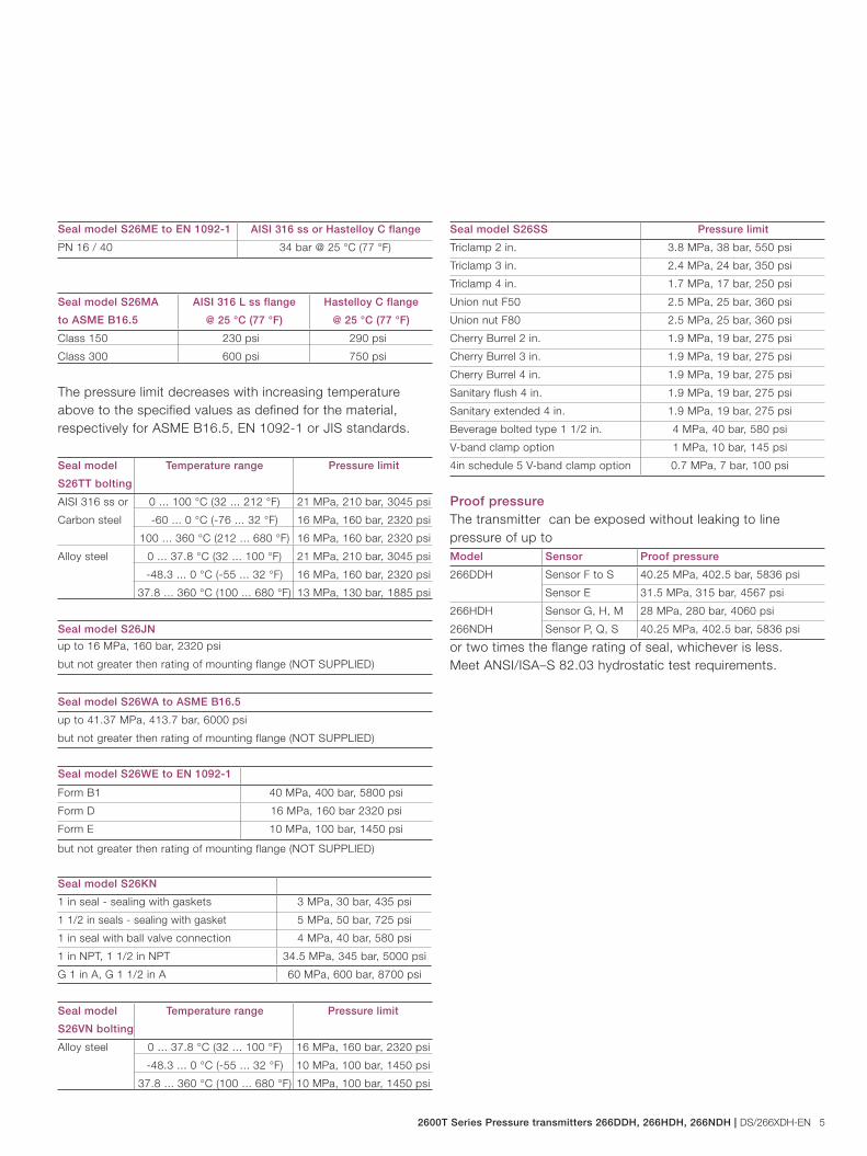
The pressure limit decreases with increasing temperature above to the specified values as defined for the material, respectively for ASME B16.5, EN 1092-1 or JIS standards.
Seal model
S26TT bolting
Temperature range Pressure limit
AISI 316 ss or
Carbon steel
0 ... 100 °C (32 ... 212 °F) 21 MPa, 210 bar, 3045 psi
-60 ... 0 °C (-76 ... 32 °F) 16 MPa, 160 bar, 2320 psi
100 ... 360 °C (212 ... 680 °F) 16 MPa, 160 bar, 2320 psi
Alloy steel 0 ... 37.8 °C (32 ... 100 °F) 21 MPa, 210 bar, 3045 psi
-48.3 ... 0 °C (-55 ... 32 °F) 16 MPa, 160 bar, 2320 psi
37.8 ... 360 °C (100 ... 680 °F) 13 MPa, 130 bar, 1885 psi
Seal model S26JN
up to 16 MPa, 160 bar, 2320 psi
but not greater then rating of mounting flange (NOT SUPPLIED)
Seal model S26WA to ASME B16.5
up to 41.37 MPa, 413.7 bar, 6000 psi
but not greater then rating of mounting flange (NOT SUPPLIED)
Seal model S26WE to EN 1092-1
Form B1 40 MPa, 400 bar, 5800 psi
Form D 16 MPa, 160 bar 2320 psi
Form E 10 MPa, 100 bar, 1450 psi
but not greater then rating of mounting flange (NOT SUPPLIED)
Seal model S26KN
1 in seal - sealing with gaskets 3 MPa, 30 bar, 435 psi
1 1/2 in seals - sealing with gasket 5 MPa, 50 bar, 725 psi
1 in seal with ball valve connection 4 MPa, 40 bar, 580 psi
1 in NPT, 1 1/2 in NPT 34.5 MPa, 345 bar, 5000 psi
G 1 in A, G 1 1/2 in A 60 MPa, 600 bar, 8700 psi
Seal model
S26VN bolting
Temperature range Pressure limit
Alloy steel 0 ... 37.8 °C (32 ... 100 °F) 16 MPa, 160 bar, 2320 psi
-48.3 ... 0 °C (-55 ... 32 °F) 10 MPa, 100 bar, 1450 psi
37.8 ... 360 °C (100 ... 680 °F) 10 MPa, 100 bar, 1450 psi
Seal model S26SS Pressure limit
Triclamp 2 in. 3.8 MPa, 38 bar, 550 psi
Triclamp 3 in. 2.4 MPa, 24 bar, 350 psi
Triclamp 4 in. 1.7 MPa, 17 bar, 250 psi
Union nut F50 2.5 MPa, 25 bar, 360 psi
Union nut F80 2.5 MPa, 25 bar, 360 psi
Cherry Burrel 2 in. 1.9 MPa, 19 bar, 275 psi
Cherry Burrel 3 in. 1.9 MPa, 19 bar, 275 psi
Cherry Burrel 4 in. 1.9 MPa, 19 bar, 275 psi
Sanitary flush 4 in. 1.9 MPa, 19 bar, 275 psi
Sanitary extended 4 in. 1.9 MPa, 19 bar, 275 psi
Beverage bolted type 1 1/2 in. 4 MPa, 40 bar, 580 psi
V-band clamp option 1 MPa, 10 bar, 145 psi
4in schedule 5 V-band clamp option 0.7 MPa, 7 bar, 100 psi
Proof pressureThe transmitter can be exposed without leaking to line pressure of up to Model Sensor Proof pressure
266DDH Sensor F to S 40.25 MPa, 402.5 bar, 5836 psi
Sensor E 31.5 MPa, 315 bar, 4567 psi
266HDH
266NDH
Sensor G, H, M 28 MPa, 280 bar, 4060 psi
Sensor P, Q, S 40.25 MPa, 402.5 bar, 5836 psi
or two times the flange rating of seal, whichever is less.Meet ANSI/ISA–S 82.03 hydrostatic test requirements.
6 DS/266XDH-EN | 2600T Series Pressure transmitters 266DDH, 266HDH, 266NDH
Model 266DDH Differential Model 266HDH Gauge Model 266NDH Absolute
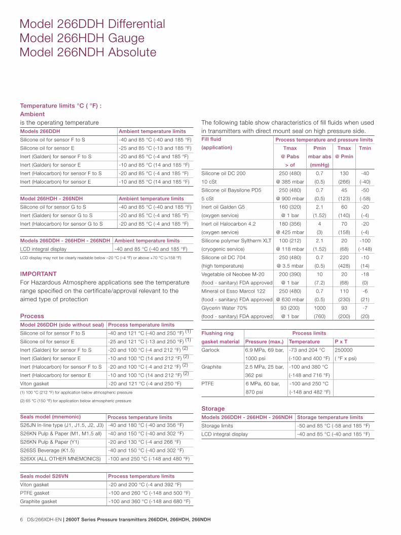
Temperature limits °C ( °F) :Ambientis the operating temperatureModels 266DDH Ambient temperature limits
Silicone oil for sensor F to S -40 and 85 °C (-40 and 185 °F)
Silicone oil for sensor E -25 and 85 °C (-13 and 185 °F)
Inert (Galden) for sensor F to S -20 and 85 °C (-4 and 185 °F)
Inert (Galden) for sensor E -10 and 85 °C (14 and 185 °F)
Inert (Halocarbon) for sensor F to S -20 and 85 °C (-4 and 185 °F)
Inert (Halocarbon) for sensor E -10 and 85 °C (14 and 185 °F)
Model 266HDH - 266NDH Ambient temperature limits
Silicone oil for sensor G to S -40 and 85 °C (-40 and 185 °F)
Inert (Galden) for sensor G to S -20 and 85 °C (-4 and 185 °F)
Inert (Halocarbon) for sensor G to S -20 and 85 °C (-4 and 185 °F)
Models 266DDH - 266HDH - 266NDH Ambient temperature limits
LCD integral display -40 and 85 °C (-40 and 185 °F)
LCD display may not be clearly readable below –20 °C (–4 °F) or above +70 °C (+158 °F)
IMPORTANTFor Hazardous Atmosphere applications see the temperature range specified on the certificate/approval relevant to the aimed type of protection
ProcessModel 266DDH (side without seal) Process temperature limits
Silicone oil for sensor F to S -40 and 121 °C (-40 and 250 °F) (1)
Silicone oil for sensor E -25 and 121 °C (-13 and 250 °F) (1)
Inert (Galden) for sensor F to S -20 and 100 °C (-4 and 212 °F) (2)
Inert (Galden) for sensor E -10 and 100 °C (14 and 212 °F) (2)
Inert (Halocarbon) for sensor F to S -20 and 100 °C (-4 and 212 °F) (2)
Inert (Halocarbon) for sensor E -10 and 100 °C (14 and 212 °F) (2)
Viton gasket -20 and 121 °C (-4 and 250 °F)
(1) 100 °C (212 °F) for application below atmospheric pressure
(2) 65 °C (150 °F) for application below atmospheric pressure
Seals model (mnemonic) Process temperature limits
S26JN In-line type (J1, J1.5, J2, J3) -40 and 180 °C (-40 and 356 °F)
S26KN Pulp & Paper (M1, M1.5 all) -40 and 150 °C (-40 and 302 °F)
S26KN Pulp & Paper (Y1) -20 and 130 °C (-4 and 266 °F)
S26SS Beverage (K1.5) -40 and 150 °C (-40 and 302 °F)
S26XX (ALL OTHER MNEMONICS) -100 and 250 °C (-148 and 480 °F)
Seals model S26VN Process temperature limits
Viton gasket -20 and 200 °C (-4 and 392 °F)
PTFE gasket -100 and 260 °C (-148 and 500 °F)
Graphite gasket -100 and 360 °C (-148 and 680 °F)
The following table show characteristics of fill fluids when used in transmitters with direct mount seal on high pressure side.Fill fluid
(application)
Process temperature and pressure limits
Tmax
@ Pabs
> of
Pmin
mbar abs
(mmHg)
Tmax
@ Pmin
Tmin
Silicone oil DC 200
10 cSt
250 (480)
@ 385 mbar
0.7
(0.5)
130
(266)
-40
(-40)
Silicone oil Baysilone PD5
5 cSt
250 (480)
@ 900 mbar
0.7
(0.5)
45
(123)
-50
(-58)
Inert oil Galden G5
(oxygen service)
160 (320)
@ 1 bar
2.1
(1.52)
60
(140)
-20
(-4)
Inert oil Halocarbon 4.2
(oxygen service)
180 (356)
@ 425 mbar
4
(3)
70
(158)
-20
(-4)
Silicone polymer Syltherm XLT
(cryogenic service)
100 (212)
@ 118 mbar
2.1
(1.52)
20
(68)
-100
(-148)
Silicone oil DC 704
(high temperature)
250 (480)
@ 3.5 mbar
0.7
(0.5)
220
(428)
-10
(14)
Vegetable oil Neobee M-20
(food - sanitary) FDA approved
200 (390)
@ 1 bar
10
(7.2)
20
(68)
-18
(0)
Mineral oil Esso Marcol 122
(food - sanitary) FDA approved
250 (480)
@ 630 mbar
0.7
(0.5)
110
(230)
-6
(21)
Glycerin Water 70%
(food - sanitary) FDA approved
93 (200)
@ 1 bar
1000
(760)
93
(200)
-7
(20)
Flushing ring
gasket material
Process limits
Pressure (max.) Temperature P x T
Garlock 6.9 MPa, 69 bar,
1000 psi
-73 and 204 °C
(-100 and 400 °F)
250000
( °F x psi)
Graphite 2.5 MPa, 25 bar,
362 psi
-100 and 380 °C
(-148 and 716 °F)
PTFE 6 MPa, 60 bar,
870 psi
-100 and 250 °C
(-148 and 482 °F)
StorageModels 266DDH - 266HDH - 266NDH Storage temperature limits
Storage limits -50 and 85 °C (-58 and 185 °F)
LCD integral display -40 and 85 °C (-40 and 185 °F)
2600T Series Pressure transmitters 266DDH, 266HDH, 266NDH | DS/266XDH-EN 7
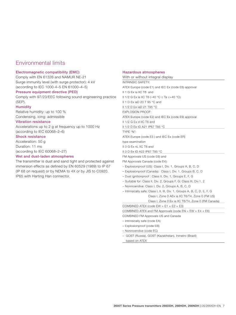
Hazardous atmospheresWith or without integral displayINTRINSIC SAFETY:
ATEX Europe (code E1) and IEC Ex (code E8) approval
II 1 G Ex ia IIC T6 and
II 1/2 G Ex ia IIC T6 (–40 °C ≤ Ta ≤+40 °C);
II 1 D Ex iaD 20 T 95 °C and
II 1/2 D Ex iaD 21 T95 °C
EXPLOSION PROOF:
ATEX Europe (code E2) and IEC Ex (code E9) approval
II 1/2 G Ex d IIC T6 and
II 1/2 D Ex tD A21 IP67 T85 °C
TYPE “N”:
ATEX Europe (code E3 ) and IEC Ex (code ER)
type examination
II 3 G Ex nL IIC T6 and
II 3 D Ex tD A22 IP67 T85 °C
FM Approvals US (code E6) and
FM Approvals Canada (code E4):
– Explosionproof (US): Class I, Div. 1, Groups A, B, C, D
– Explosionproof (Canada): Class I, Div. 1, Groups B, C, D
– Dust ignitionproof : Class II, Div. 1, Groups E, F, G
– Suitable for: Class II, Div. 2, Groups F, G; Class III, Div.1, 2
– Nonincendive: Class I, Div. 2, Groups A, B, C, D
– Intrinsically safe: Class I, II, III, Div. 1, Groups A, B, C, D, E, F, G
Class I, Zone 0 AEx ia IIC T6/T4, Zone 0 (FM US)
Class I, Zone 0 Ex ia IIC T6/T4, Zone 0 (FM Canada)
COMBINED ATEX (code EW = E1 + E2 + E3)
COMBINED ATEX and FM Approvals (code EN = EW + E4 + E6)
COMBINED FM Approvals US and Canada
– Intrinsically safe (code EA)
– Explosionproof (code EB)
– Nonincendive (code EC)
– GOST (Russia), GOST (Kazakhstan), Inmetro (Brazil)
based on ATEX
Environmental limits
Electromagnetic compatibility (EMC)Comply with EN 61326 and NAMUR NE-21Surge immunity level (with surge protector): 4 kV(according to IEC 1000-4–5 EN 61000–4–5)Pressure equipment directive (PED)Comply with 97/23/EEC following sound engineering practice (SEP).HumidityRelative humidity: up to 100 %Condensing, icing: admissibleVibration resistanceAccelerations up to 2 g at frequency up to 1000 Hz(according to IEC 60068–2–6)Shock resistanceAcceleration: 50 gDuration: 11 ms(according to IEC 60068–2–27)Wet and dust-laden atmospheresThe transmitter is dust and sand tight and protected against immersion effects as defined by EN 60529 (1989) to IP 67 (IP 68 on request) or by NEMA to 4X or by JIS to C0920. IP65 with Harting Han connector.
8 DS/266XDH-EN | 2600T Series Pressure transmitters 266DDH, 266HDH, 266NDH
Model 266DDH Differential Model 266HDH Gauge Model 266NDH Absolute
Electrical Characteristics and Options
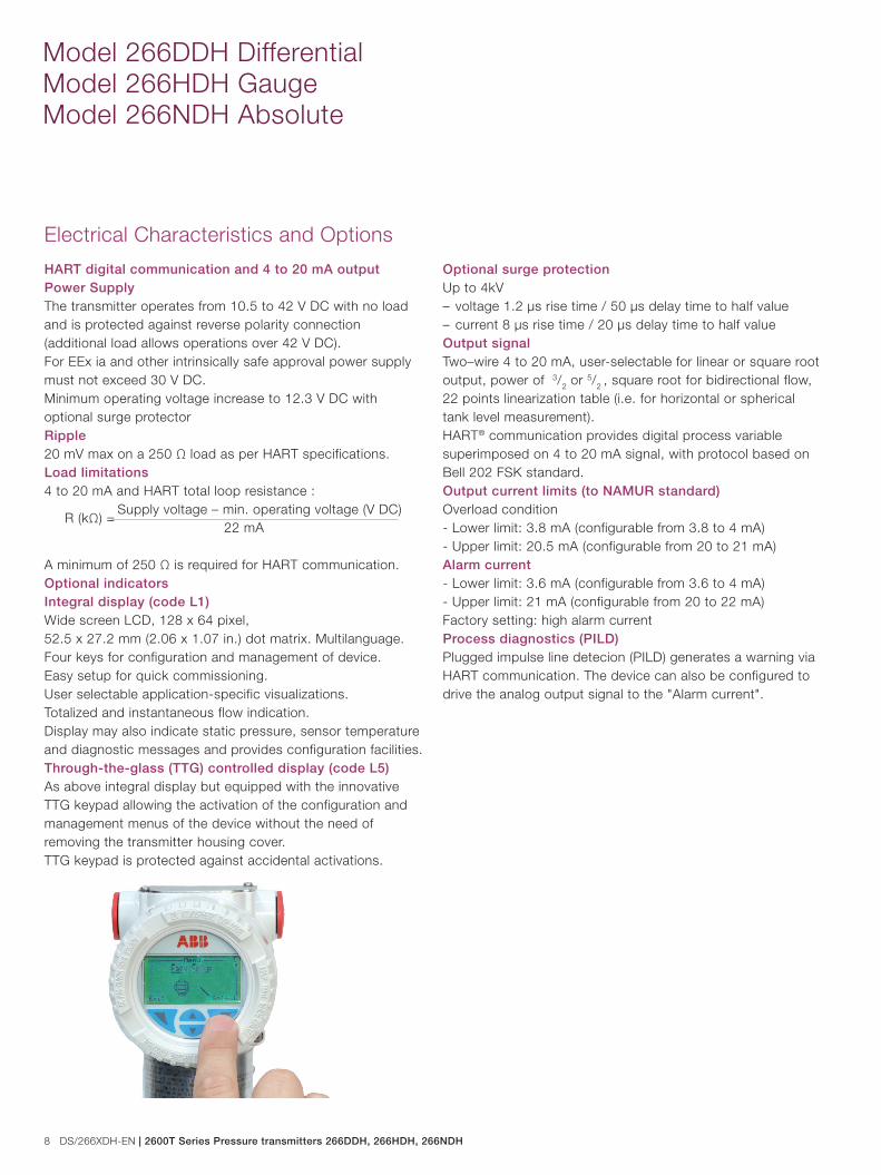
HART digital communication and 4 to 20 mA outputPower SupplyThe transmitter operates from 10.5 to 42 V DC with no load and is protected against reverse polarity connection (additional load allows operations over 42 V DC). For EEx ia and other intrinsically safe approval power supply must not exceed 30 V DC.Minimum operating voltage increase to 12.3 V DC with optional surge protectorRipple20 mV max on a 250 Ω load as per HART specifications.Load limitations 4 to 20 mA and HART total loop resistance :
A minimum of 250 Ω is required for HART communication.Optional indicatorsIntegral display (code L1)Wide screen LCD, 128 x 64 pixel, 52.5 x 27.2 mm (2.06 x 1.07 in.) dot matrix. Multilanguage.Four keys for configuration and management of device.Easy setup for quick commissioning.User selectable application-specific visualizations.Totalized and instantaneous flow indication.Display may also indicate static pressure, sensor temperature and diagnostic messages and provides configuration facilities.Through-the-glass (TTG) controlled display (code L5)As above integral display but equipped with the innovative TTG keypad allowing the activation of the configuration and management menus of the device without the need of removing the transmitter housing cover. TTG keypad is protected against accidental activations.
Optional surge protection Up to 4kV – voltage 1.2 µs rise time / 50 µs delay time to half value– current 8 µs rise time / 20 µs delay time to half valueOutput signalTwo–wire 4 to 20 mA, user-selectable for linear or square root output, power of 3/2 or 5/2 , square root for bidirectional flow, 22 points linearization table (i.e. for horizontal or spherical tank level measurement). HART® communication provides digital process variable superimposed on 4 to 20 mA signal, with protocol based on Bell 202 FSK standard. Output current limits (to NAMUR standard) Overload condition- Lower limit: 3.8 mA (configurable from 3.8 to 4 mA)- Upper limit: 20.5 mA (configurable from 20 to 21 mA)Alarm current - Lower limit: 3.6 mA (configurable from 3.6 to 4 mA)- Upper limit: 21 mA (configurable from 20 to 22 mA)Factory setting: high alarm currentProcess diagnostics (PILD)Plugged impulse line detecion (PILD) generates a warning via HART communication. The device can also be configured to drive the analog output signal to the "Alarm current".
Supply voltage – min. operating voltage (V DC) 22 mA
R (kΩ) =
2600T Series Pressure transmitters 266DDH, 266HDH, 266NDH | DS/266XDH-EN 9
FOUNDATION Fieldbus outputDevice type LINK MASTER DEVICELink Active Scheduler (LAS) capability implemented.Manufacturer code: 000320 (hex)Device type code: 0007 (hex)Power supplyThe transmitter operates from 9 to 32 V DC, polarity independent, with or without surge protector.For EEx ia approval power supply must not exceed 24 V DC (entity certification) or 17.5 V DC (FISCO certification), according to FF–816.Current consumptionoperating (quiescent): 15 mAfault current limiting: 20 mA max.Output signalPhysical layer in compliance to IEC 1158–2/EN 61158–2 with transmission to Manchester II modulation, at 31.25 kbit/s.Function blocks/execution period3 enhanced Analog Input blocks/25 ms max (each)1 enhanced PID block/40 ms max.1 standard ARitmetic block/25 ms1 standard Input Selector block/25 ms1 standard Control Selector block/25 ms1 standard Signal Characterization block/25 ms1 standard Integrator/Totalizer block/25 msAdditional blocks1 enhanced Resource block,1 custom Pressure with calibration transducer block1 custom Advanced Diagnostics transducer block including Plugged Input Line Detection1 custom Local Display transducer blockNumber of link objects35Number of VCRs 35
Output interfaceFOUNDATION fieldbus digital communication protocol to standard H1, compliant to specification V. 1.7.Integral displayWide screen LCD, 128 x 64 pixel,52.5 x 27.2 mm (2.06 x 1.07 in.) dot matrix. Multilanguage.Four keys for configuration and management of device.Easy setup for quick commissioning.User selectable application-specific visualizations.Totalized and instantaneous flow indication.Display may also indicate static pressure, sensor temperature and diagnostic messages and provides configuration facilities.Transmitter failure modeThe output signal is “frozen” to the last valid value on gross transmitter failure condition, detected by self-diagnostics which also indicate a BAD conditions. If electronic failure or short circuit occur the transmitter consumption is electronically limited at a defined value (20 mA approx), for safety of the network.
10 DS/266XDH-EN | 2600T Series Pressure transmitters 266DDH, 266HDH, 266NDH
Model 266DDH Differential Model 266HDH Gauge Model 266NDH Absolute
PROFIBUS PA outputDevice typePressure transmitter compliant to Profiles 3.0.1Identification number: 3450 (hex)Power supplyThe transmitter operates from 9 to 32 V DC , polarity independent, with or without surge protector.For EEx ia approval power supply must not exceed 17.5 V DC.Intrinsic safety installation according to FISCO model. Current consumptionoperating (quiescent): 15 mAfault current limiting: 20 mA max.Output signalPhysical layer in compliance to IEC 1158–2/EN 61158–2 with transmission to Manchester II modulation, at 31.25 kbit/s.Output interfacePROFIBUS PA communication according to Profibus DP50170 Part 2/DIN 19245 part 1–3. Output update time 25 msFunction blocks3 analog input, 3 transducer, 1 physical.Integral displayWide screen LCD, 128 x 64 pixel,52.5 x 27.2 mm (2.06 x 1.07 in.) dot matrix. Multilanguage.Four keys for configuration and management of device.Easy setup for quick commissioning.User selectable application-specific visualizations.Instantaneous flow indication.Display may also indicate static pressure, sensor temperature and diagnostic messages and provides configuration facilities.Transmitter failure modeOn gross transmitter failure condition, detected by self-diagnostics, the output signal can be driven to defined conditions, selectable by the user as safe, last valid or calculated value. If electronic failure or short circuit occur the transmitter consumption is electronically limited at a defined value (20 mA approx), for safety of the network.
Performance specifications
Stated at reference condition to IEC 60770 ambient temperature of 20 °C (68 °F), relative humidity of 65 %, atmospheric pressure of 1013 hPa (1013 mbar), mounting position with vertical diaphragm and zero based range for transmitter with isolating diaphragms in AISI 316 L ss or Hastelloy and silicone oil fill and HART digital trim values equal to 4 mA and to 20 mA span end points, in linear mode. Unless otherwise specified, errors are quoted as % of span.Some performance referring to the Upper Range Limit are affected by the actual turndown (TD) as ratio between Upper Range Limit (URL) and calibrated span.IT IS RECOMMENDED TO SELECT THE TRANSMITTER SENSOR CODE PROVIDING THE TURNDOWN VALUE AS LOWEST AS POSSIBLE TO OPTIMIZE PERFORMANCE CHARACTERISTICS.
Accuracy rating% of calibrated span, including combined effects of terminal based linearity, hysteresis and repeatability.For fieldbus versions SPAN refer to analog input function block outscale rangeModel Sensor for TD up to
266DDH
with seals
mnemonic
P3, F3, E3, S3,
K1.5, F2
F and G from 1:1 to 10:1 ± 0.06 %
F and G from 10:1 to 60:1 ± (0.006 x TD) %
H to S from 1:1 to 10:1 ± 0.075 %
H to S from 10:1 to 60:1 ± (0.0075 x TD) %
E from 1:1 to 5:1 ± 0.10 %
E from 5:1 to 20:1 ± (0.02 x TD) %
266DDH with
seals mnemonic
different from
above
F to S from 1:1 to 10:1 ± 0.10 %
F to S from 10:1 to 60:1 ± (0.01 x TD) %
E from 1:1 to 5:1 ± 0.15 %
E from 5:1 to 20:1 ± (0.03 x TD) %
2600T Series Pressure transmitters 266DDH, 266HDH, 266NDH | DS/266XDH-EN 11
Accuracy rating% of calibrated span, including combined effects of terminal based linearity, hysteresis and repeatability.For fieldbus versions SPAN refer to analog input function block outscale rangeModel Sensor for TD up to
266HDH with seals
mnemonic
P3, F3, E3, S3, K1.5, F2
M and P from 1:1 to 10:1 ± 0.06 %
M and P from 10:1 to 60:1 ± (0.006 x TD) %
G, H, Q, S from 1:1 to 10:1 ± 0.075 %
G, H, Q, S from 10:1 to 60:1 ± (0.0075 x TD) %
266HDH
with seals mnemonic
Y1
H and M from 1:1 to 5:1 ± 0.15 %
H and M from 5:1 to 30:1 ± (0.03 x TD) %
P, Q from 1:1 to 5:1 ± 0.075 %
P, Q from 5:1 to 30:1 ± (0.015 x TD) %
266HDH
with seals mnemonic
M1
H and M from 1:1 to 5:1 ± 0.15 %
H and M from 5:1 to 30:1 ± (0.03 x TD) %
P, Q, S from 1:1 to 5:1 ± 0.075 %
P, Q, S from 5:1 to 30:1 ± (0.015 x TD) %
266HDH with seals
mnemonic M1.5, M1.5B
G, H, M,
P, Q
from 1:1 to 5:1 ± 0.075 %
from 5:1 to 30:1 ± (0.015 x TD) %
266HDH with seals
mnemonic M1.5A
G, H, M,
P, Q, S
from 1:1 to 5:1 ± 0.075 %
from 5:1 to 30:1 ± (0.015 x TD) %
266HDH with seals
different from above
G, H, M,
P, Q, S
from 1:1 to 10:1 ± 0.10 %
from 10:0 to 60:1 ± (0.01 x TD) %
266NDH with seals
mnemonic P3, F3, E3,
S3, K1.5, F2
G, H, M,
P, Q, S
from 1:1 to 10:1 ± 0.10 %
from 10:1 to 60:1 ± (0.01 x TD) %
266NDH
with seals mnemonic
M1
H and M from 1:1 to 5:1 ± 0.20 %
H and M from 5:1 to 30:1 ± (0.04 x TD) %
P, Q, S from 1:1 to 5:1 ± 0.10 %
P, Q, S from 5:1 to 30:1 ± (0.02 x TD) %
266NDH with seals
mnemonic M1.5, M1.5B
G, H, M,
P, Q
from 1:1 to 5:1 ± 0.10 %
from 5:1 to 30:1 ± (0.02 x TD) %
266NDH with seals
mnemonic M1.5A
G, H, M,
P, Q, S
from 1:1 to 5:1 ± 0.10 %
from 5:1 to 30:1 ± (0.02 x TD) %
266NDH with seals
different from above
G, H, M,
P, Q, S
from 1:1 to 10:1 ± 0.15 %
from 10:1 to 60:1 ± (0.015 x TD) %
Ambient temperature Transmitter effect per 20K change between the limits of –40 °C to +85 °C (per 36 °F change between the limits of –40 to +185 °F): Model Sensor for TD up to
266DDH E to S 10 : 1 ± (0.04 % URL + 0.065 % span)
266HDH G to S 10 : 1 ± (0.04 % URL + 0.065 % span)
266NDH G to S 10 : 1 ± (0.08 % URL + 0.13 % span)
REFER TO S26 SEALS DATA SHEET FOR TEMPERATURE ADDITIONAL EFFECTS OF DIRECT MOUNT SEAL AND REMOTE SEAL (if selected on negative side).
For paper and in-line seal, available only as direct mount, refer respectively to the following tables of temperature effects per 20 K (36 °F) changes, detailed separately for- the seal (one element), as process temperature error- the system (transmitter sensor when combined with a seal of specific size/type) referred to silicone oil (DC 200) filling and AISI 316 L ss diaphragm materials. .S26K paper seal
size - Mnemonic
Sensor
URL
Seal error
(process)
Direct mount
error (ambient)
1 in. - Y1 ≥ 160 kPa,
642 inH2O
1.2 kPa,
4.8 inH2O
0.64 kPa,
2.56 inH2O
1 in. - M1 ≥ 160 kPa,
642 inH2O
0.6 kPa,
2.4 inH2O
0.64 kPa,
2.56 inH2O
1 1/2 in. - M1.5 ≥ 65 kPa,
260 inH2O
0.2 kPa,
0.8 inH2O
0.48 kPa,
1.92 inH2O
1 1/2 in. - M1.5A ≥ 65 kPa,
260 inH2O
0.2 kPa,
0.8 inH2O
0.48 kPa,
1.92 inH2O
1 1/2 in. - M1.5B ≥ 65 kPa,
260 inH2O
0.2 kPa,
0.8 inH2O
0.48 kPa,
1.92 inH2O
S26J in-line seal
size - Mnemonic
Sensor
URL
Seal error
(process)
Direct mount
error (ambient)
1 in. - J1 ≥ 600 kPa,
87 psi
2.2 kPa,
8.8 inH2O
0.94 kPa,
3.76 inH2O
1 1/2 in. - J1.5 ≥ 600 kPa,
87 psi
1.4 kPa,
5.6 inH2O
0.36 kPa,
1.44 inH2O
2 in. - J2 ≥ 600 kPa,
87 psi
4.6 kPa,
18.4 inH2O
0.94 kPa,
3.76 inH2O
4 in. - J3 ≥ 600 kPa,
87 psi
3.0 kPa,
12 inH2O
0.42 kPa,
1.68 inH2O
Static pressure (zero errors can be calibrated out at line pressure) per 2 MPa, 20 bar or 290 psi Model 266DDH with direct mount seal only– zero error: ±0.15% of URL– span error: ±0.15% of readingModel 266DDH with direct mount plus remote seal– zero error: ±0.20% of URL– span error: ±0.20% of readingSupply voltageWithin voltage/load specified limits the total effect is less than 0.005 % of URL per volt.LoadWithin load/voltage specified limits the total effect is negligible.Electromagnetic fieldMeets all the requirements of EN 61326 and NAMUR NE-21.Common mode interferenceNo effect from 100Vrms @ 50Hz, or 50 V DC
12 DS/266XDH-EN | 2600T Series Pressure transmitters 266DDH, 266HDH, 266NDH
Model 266DDH Differential Model 266HDH Gauge Model 266NDH Absolute
Physical Specification
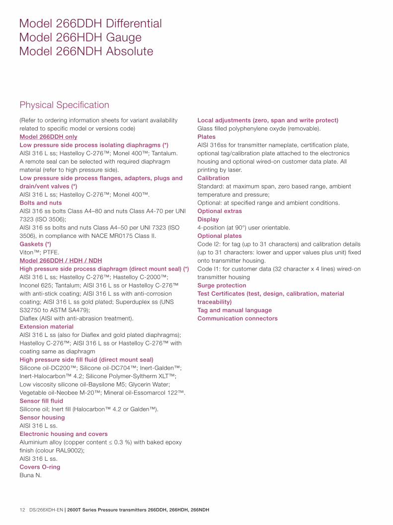
(Refer to ordering information sheets for variant availability related to specific model or versions code)Model 266DDH onlyLow pressure side process isolating diaphragms (*)AISI 316 L ss; Hastelloy C-276™; Monel 400™; Tantalum.A remote seal can be selected with required diaphragm material (refer to high pressure side).Low pressure side process flanges, adapters, plugs and drain/vent valves (*)AISI 316 L ss; Hastelloy C-276™; Monel 400™.Bolts and nutsAISI 316 ss bolts Class A4–80 and nuts Class A4-70 per UNI 7323 (ISO 3506);AISI 316 ss bolts and nuts Class A4–50 per UNI 7323 (ISO 3506), in compliance with NACE MR0175 Class II.Gaskets (*)Viton™; PTFE.Model 266DDH / HDH / NDHHigh pressure side process diaphragm (direct mount seal) (*)AISI 316 L ss; Hastelloy C-276™; Hastelloy C-2000™;Inconel 625; Tantalum; AISI 316 L ss or Hastelloy C-276™ with anti-stick coating; AISI 316 L ss with anti-corrosion coating; AISI 316 L ss gold plated; Superduplex ss (UNS S32750 to ASTM SA479);Diaflex (AISI with anti-abrasion treatment).Extension materialAISI 316 L ss (also for Diaflex and gold plated diaphragms);Hastelloy C-276™; AISI 316 L ss or Hastelloy C-276™ with coating same as diaphragmHigh pressure side fill fluid (direct mount seal)Silicone oil-DC200™; Silicone oil-DC704™; Inert-Galden™;Inert-Halocarbon™ 4.2; Silicone Polymer-Syltherm XLT™;Low viscosity silicone oil-Baysilone M5; Glycerin Water;Vegetable oil-Neobee M-20™; Mineral oil-Essomarcol 122™.Sensor fill fluidSilicone oil; Inert fill (Halocarbon™ 4.2 or Galden™).Sensor housingAISI 316 L ss.Electronic housing and coversAluminium alloy (copper content ≤ 0.3 %) with baked epoxy finish (colour RAL9002);AISI 316 L ss.Covers O-ringBuna N.
Local adjustments (zero, span and write protect)Glass filled polyphenylene oxyde (removable).PlatesAISI 316ss for transmitter nameplate, certification plate, optional tag/calibration plate attached to the electronics housing and optional wired-on customer data plate. All printing by laser.CalibrationStandard: at maximum span, zero based range, ambient temperature and pressure;Optional: at specified range and ambient conditions.Optional extrasDisplay4-position (at 90°) user orientable.Optional platesCode I2: for tag (up to 31 characters) and calibration details (up to 31 characters: lower and upper values plus unit) fixed onto transmitter housing.Code I1: for customer data (32 character x 4 lines) wired-on transmitter housingSurge protectionTest Certificates (test, design, calibration, material traceability)Tag and manual languageCommunication connectors
2600T Series Pressure transmitters 266DDH, 266HDH, 266NDH | DS/266XDH-EN 13
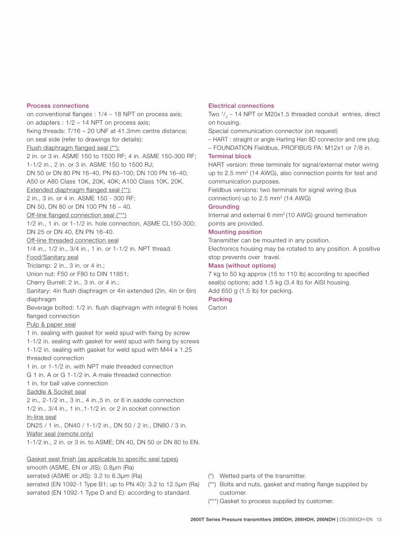
Process connections on conventional flanges : 1/4 – 18 NPT on process axis;on adapters : 1/2 – 14 NPT on process axis;fixing threads: 7/16 – 20 UNF at 41.3mm centre distance;on seal side (refer to drawings for details):Flush diaphragm flanged seal (**):2 in. or 3 in. ASME 150 to 1500 RF; 4 in. ASME 150-300 RF;1-1/2 in., 2 in. or 3 in. ASME 150 to 1500 RJ;DN 50 or DN 80 PN 16–40, PN 63–100; DN 100 PN 16–40;A50 or A80 Class 10K, 20K, 40K; A100 Class 10K, 20K.Extended diaphragm flanged seal (**):2 in., 3 in. or 4 in. ASME 150 - 300 RF;DN 50, DN 80 or DN 100 PN 16 – 40.Off-line flanged connection seal (***)1/2 in., 1 in. or 1-1/2 in. hole connection, ASME CL150-300;DN 25 or DN 40, EN PN 16-40.Off-line threaded connection seal1/4 in., 1/2 in., 3/4 in., 1 in. or 1-1/2 in. NPT thread.Food/Sanitary sealTriclamp: 2 in., 3 in. or 4 in.;Union nut: F50 or F80 to DIN 11851;Cherry Burrell: 2 in., 3 in. or 4 in.;Sanitary: 4in flush diaphragm or 4in extended (2in, 4in or 6in)diaphragmBeverage bolted: 1/2 in. flush diaphragm with integral 6 holes flanged connectionPulp & paper seal1 in. sealing with gasket for weld spud with fixing by screw1-1/2 in. sealing with gasket for weld spud with fixing by screws1-1/2 in. sealing with gasket for weld spud with M44 x 1.25 threaded connection1 in. or 1-1/2 in. with NPT male threaded connectionG 1 in. A or G 1-1/2 in. A male threaded connection1 in. for ball valve connectionSaddle & Socket seal2 in., 2-1/2 in., 3 in., 4 in.,5 in. or 6 in.saddle connection1/2 in., 3/4 in., 1 in.,1-1/2 in. or 2 in.socket connectionIn-line sealDN25 / 1 in., DN40 / 1-1/2 in., DN 50 / 2 in., DN80 / 3 in.Wafer seal (remote only)1-1/2 in., 2 in. or 3 in. to ASME; DN 40, DN 50 or DN 80 to EN.
Gasket seat finish (as applicable to specific seal types)smooth (ASME, EN or JIS): 0.8μm (Ra)serrated (ASME or JIS): 3.2 to 6.3μm (Ra)serrated (EN 1092-1 Type B1; up to PN 40): 3.2 to 12.5μm (Ra)serrated (EN 1092-1 Type D and E): according to standard.
Electrical connectionsTwo 1/2 – 14 NPT or M20x1.5 threaded conduit entries, direct on housing.Special communication connector (on request)– HART : straight or angle Harting Han 8D connector and one plug.– FOUNDATION Fieldbus, PROFIBUS PA: M12x1 or 7/8 in.Terminal blockHART version: three terminals for signal/external meter wiring up to 2.5 mm2 (14 AWG), also connection points for test and communication purposes.Fieldbus versions: two terminals for signal wiring (bus connection) up to 2.5 mm2 (14 AWG)Grounding Internal and external 6 mm2 (10 AWG) ground termination points are provided.Mounting positionTransmitter can be mounted in any position. Electronics housing may be rotated to any position. A positive stop prevents over travel.Mass (without options)7 kg to 50 kg approx (15 to 110 lb) according to specified seal(s) options; add 1.5 kg (3.4 lb) for AISI housing.Add 650 g (1.5 lb) for packing.PackingCarton
(*) Wetted parts of the transmitter.(**) Bolts and nuts, gasket and mating flange supplied by customer.(***) Gasket to process supplied by customer.
14 DS/266XDH-EN | 2600T Series Pressure transmitters 266DDH, 266HDH, 266NDH
Model 266DDH Differential Model 266HDH Gauge Model 266NDH Absolute
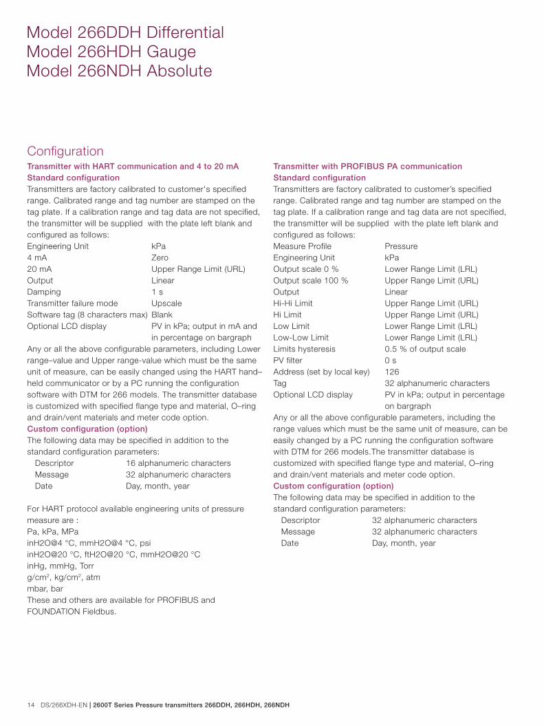
ConfigurationTransmitter with HART communication and 4 to 20 mAStandard configurationTransmitters are factory calibrated to customer's specified range. Calibrated range and tag number are stamped on the tag plate. If a calibration range and tag data are not specified, the transmitter will be supplied with the plate left blank and configured as follows:Engineering Unit kPa4 mA Zero20 mA Upper Range Limit (URL)Output LinearDamping 1 sTransmitter failure mode UpscaleSoftware tag (8 characters max) BlankOptional LCD display PV in kPa; output in mA and in percentage on bargraphAny or all the above configurable parameters, including Lower range–value and Upper range-value which must be the same unit of measure, can be easily changed using the HART hand–held communicator or by a PC running the configuration software with DTM for 266 models. The transmitter database is customized with specified flange type and material, O–ring and drain/vent materials and meter code option.Custom configuration (option)The following data may be specified in addition to the standard configuration parameters: Descriptor 16 alphanumeric characters Message 32 alphanumeric characters Date Day, month, year
For HART protocol available engineering units of pressure measure are :Pa, kPa, MPainH2O@4 °C, mmH2O@4 °C, psiinH2O@20 °C, ftH2O@20 °C, mmH2O@20 °CinHg, mmHg, Torrg/cm2, kg/cm2, atmmbar, barThese and others are available for PROFIBUS and FOUNDATION Fieldbus.
Transmitter with PROFIBUS PA communicationStandard configurationTransmitters are factory calibrated to customer’s specified range. Calibrated range and tag number are stamped on the tag plate. If a calibration range and tag data are not specified, the transmitter will be supplied with the plate left blank and configured as follows:Measure Profile PressureEngineering Unit kPaOutput scale 0 % Lower Range Limit (LRL)Output scale 100 % Upper Range Limit (URL)Output LinearHi-Hi Limit Upper Range Limit (URL) Hi Limit Upper Range Limit (URL)Low Limit Lower Range Limit (LRL) Low-Low Limit Lower Range Limit (LRL)Limits hysteresis 0.5 % of output scalePV filter 0 sAddress (set by local key) 126Tag 32 alphanumeric charactersOptional LCD display PV in kPa; output in percentage on bargraphAny or all the above configurable parameters, including the range values which must be the same unit of measure, can be easily changed by a PC running the configuration software with DTM for 266 models.The transmitter database is customized with specified flange type and material, O–ring and drain/vent materials and meter code option.Custom configuration (option)The following data may be specified in addition to the standard configuration parameters: Descriptor 32 alphanumeric characters Message 32 alphanumeric characters Date Day, month, year
2600T Series Pressure transmitters 266DDH, 266HDH, 266NDH | DS/266XDH-EN 15
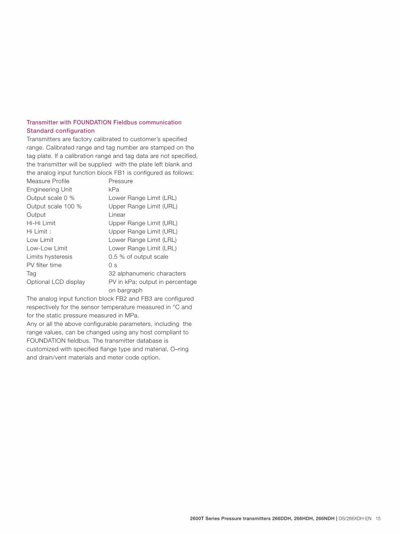
Transmitter with FOUNDATION Fieldbus communicationStandard configurationTransmitters are factory calibrated to customer’s specified range. Calibrated range and tag number are stamped on the tag plate. If a calibration range and tag data are not specified, the transmitter will be supplied with the plate left blank and the analog input function block FB1 is configured as follows:Measure Profile PressureEngineering Unit kPaOutput scale 0 % Lower Range Limit (LRL)Output scale 100 % Upper Range Limit (URL)Output LinearHi-Hi Limit Upper Range Limit (URL) Hi Limit : Upper Range Limit (URL)Low Limit Lower Range Limit (LRL) Low-Low Limit Lower Range Limit (LRL)Limits hysteresis 0.5 % of output scalePV filter time 0 sTag 32 alphanumeric charactersOptional LCD display PV in kPa; output in percentage on bargraphThe analog input function block FB2 and FB3 are configured respectively for the sensor temperature measured in °C and for the static pressure measured in MPa.Any or all the above configurable parameters, including the range values, can be changed using any host compliant to FOUNDATION fieldbus. The transmitter database is customized with specified flange type and material, O–ring and drain/vent materials and meter code option.
16 DS/266XDH-EN | 2600T Series Pressure transmitters 266DDH, 266HDH, 266NDH
Model 266DDH Differential Model 266HDH Gauge Model 266NDH Absolute
141 (5.55)
Ø D
Ø BØ A
GF
Ø C
Ø E
71 (2.8)
29 (1.14)
18 (0.71)18 (0.71)
210
(8.2
8)
56 (2.21) 53 (2.09)
66 (2.60) with plug78 (3.07) with d/v valve
102 (4.02)
9 (0.35)
11.1
(0.4
3)
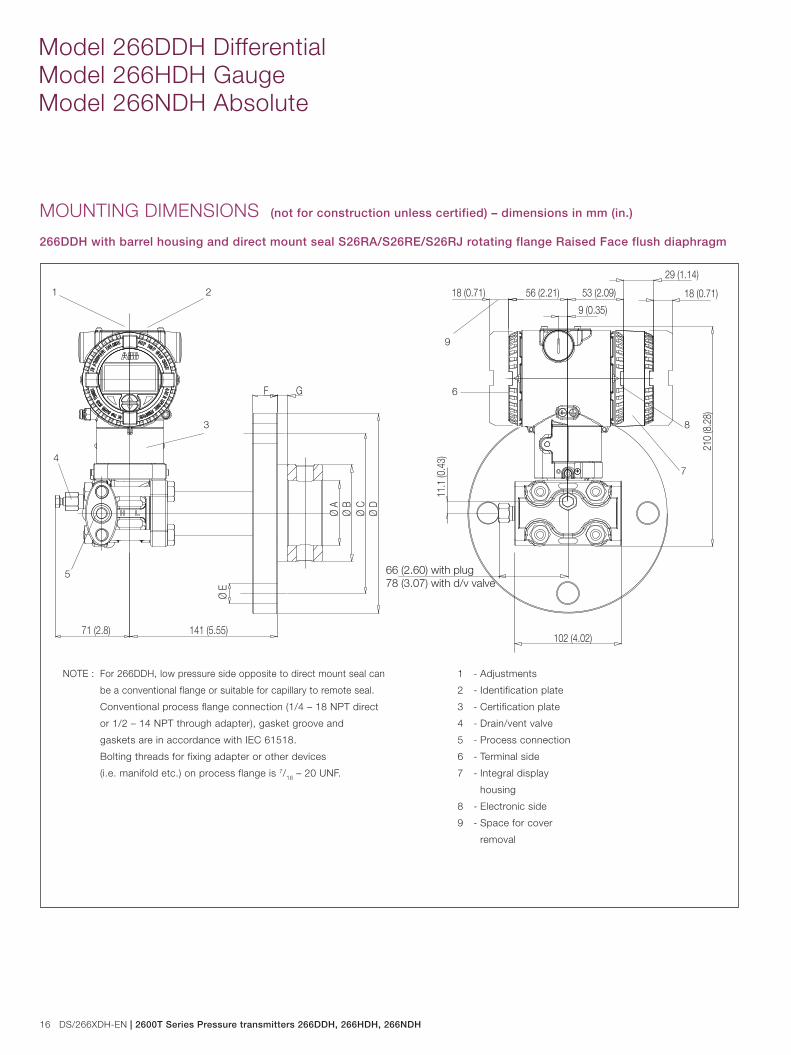
MOUNTING DIMENSIONS (not for construction unless certified) – dimensions in mm (in.)
266DDH with barrel housing and direct mount seal S26RA/S26RE/S26RJ rotating flange Raised Face flush diaphragm
NOTE : For 266DDH, low pressure side opposite to direct mount seal can
be a conventional flange or suitable for capillary to remote seal.
Conventional process flange connection (1/4 – 18 NPT direct
or 1/2 – 14 NPT through adapter), gasket groove and
gaskets are in accordance with IEC 61518.
Bolting threads for fixing adapter or other devices
(i.e. manifold etc.) on process flange is 7/16 – 20 UNF.
3
21
4
5
6
8
7
9
1 - Adjustments
2 - Identification plate
3 - Certification plate
4 - Drain/vent valve
5 - Process connection
6 - Terminal side
7 - Integral display
housing
8 - Electronic side
9 - Space for cover
removal
2600T Series Pressure transmitters 266DDH, 266HDH, 266NDH | DS/266XDH-EN 17
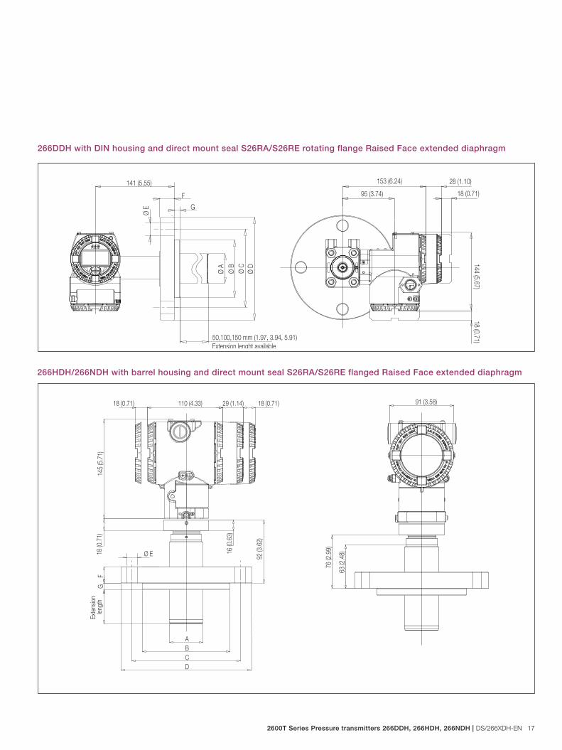
266DDH with DIN housing and direct mount seal S26RA/S26RE rotating flange Raised Face extended diaphragm
18 (0.71)
18 (0.71)141 (5.55)
144 (5.67)
95 (3.74)
153 (6.24) 28 (1.10)
Ø C
Ø E
Ø D
Ø A Ø B
50,100,150 mm (1.97, 3.94, 5.91)
F
Extension lenght available
G
266HDH/266NDH with barrel housing and direct mount seal S26RA/S26RE flanged Raised Face extended diaphragm
16 (0
.63)
ABCD
FG
Exte
nsio
n len
gth
18 (0.71)
18 (0
.71)
18 (0.71) 110 (4.33) 29 (1.14)
145
(5.7
1)
92 (3
.62)
Ø E
63 (2
.48)
91 (3.58)
76 (2
.99)
18 DS/266XDH-EN | 2600T Series Pressure transmitters 266DDH, 266HDH, 266NDH
Model 266DDH Differential Model 266HDH Gauge Model 266NDH Absolute
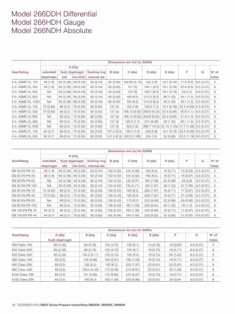
Size/Rating
Dimensions mm (in) for S26RA
A (dia)
B (dia) C (dia) D (dia) E (dia) F G N° of
holes
extended
diaphragm
flush diaphragm flushing ring
internal diastd. low thick.
2 in. ASME CL 150 48 (1.9) 60 (2.36) 58 (2.28) 62 (2.44) 92 (3.62) 120.65 (4.75) 152.4 (6) 19.1 (0.79) 17.5 (0.6) 9.5 (0.37) 4
2 in. ASME CL 300 48 (1.9) 60 (2.36) 58 (2.28) 62 (2.44) 92 (3.62) 127 (5) 165.1 (6.5) 19.1 (0.79) 20.8 (0.8) 9.5 (0.37) 8
2 in. ASME CL 600 NA 60 (2.36) 58 (2.28) 62 (2.44) 92 (3.62) 127 (5) 165.1 (6.5) 19.1 (0.79) 25.4 (1) 9.5 (0.37) 8
2 in. ASME CL 900 NA 60 (2.36) 58 (2.28) 62 (2.44) 92 (3.62) 165 (6.5) 215.9 (8.5) 26 (1.02) 38.1 (1.5) 9.5 (0.37) 8
2 in. ASME CL 1500 NA 60 (2.36) 58 (2.28) 62 (2.44) 92 (3.62) 165 (6.5) 215.9 (8.5) 26 (1.02) 38.1 (1.5) 9.5 (0.37) 8
3 in. ASME CL 150 72 (2.83) 89 (3.5) 75 (2.95) 92 (3.62) 127 (5) 152.4 (6) 190.5 (7.5) 19.1 (0.79) 22.4 (0.88) 9.5 (0.37) 4
3 in. ASME CL 300 72 (2.83) 89 (3.5) 75 (2.95) 92 (3.62) 127 (5) 168.15 (6.62) 209.6 (8.25) 22.4 (0.88) 26.9 (1.1) 9.5 (0.37) 8
3 in. ASME CL 600 NA 89 (3.5) 75 (2.95) 92 (3.62) 127 (5) 168.15 (6.62) 209.6 (8.25) 22.4 (0.88) 31.8 (1.3) 9.5 (0.37) 8
3 in. ASME CL 900 NA 89 (3.5) 75 (2.95) 92 (3.62) 127 (5) 190.5 (7.5) 241 (9.48) 26 (1.02) 38.1 (1.5) 9.5 (0.37) 8
3 in. ASME CL1500 NA 89 (3.5) 75 (2.95) 92 (3.62) 127 (5) 203.2 (8) 266.7 (10.5) 31.75 (1.25) 47.7 (1.88) 9.5 (0.37) 8
4 in. ASME CL 150 94 (3.7) 89 (3.5) 75 (2.95) 92 (3.62) 157.2 (6.2) 190.5 (7.5) 228.6 (9) 19.1 (0.79) 22.4 (0.88) 9.5 (0.37) 8
4 in. ASME CL 300 94 (3.7) 89 (3.5) 75 (2.95) 92 (3.62) 157.2 (6.2) 200.2 (7.88) 254 (10) 22 (0.86) 30.2 (1.19) 9.5 (0.37) 8
Size/Rating
Dimensions mm (in) for S26RE
A (dia)
B (dia) C (dia) D (dia) E (dia) F G N° of
holes
extended
diaphragm
flush diaphragm flushing ring
internal diastd. low thick.
DN 50 EN PN 16 48 (1.9) 60 (2.36) 58 (2.28) 62 (2.44) 102 (4.02) 125 (4.92) 165 (6.5) 18 (0.71) 15 (0.58) 9.5 (0.37) 4
DN 50 EN PN 40 48 (1.9) 60 (2.36) 58 (2.28) 62 (2.44) 102 (4.02) 125 (4.92) 165 (6.5) 18 (0.71) 18 (0.67) 9.5 (0.37) 4
DN 50 EN PN 63 NA 60 (2.36) 58 (2.28) 62 (2.44) 102 (4.02) 135 (5.31) 180 (7.08) 22 (0.86) 23 (0.9) 9.5 (0.37) 4
DN 50 EN PN 100 NA 60 (2.36) 58 (2.28) 62 (2.44) 102 (4.02) 145 (5.71) 195 (7.67) 26 (1.02) 27 (1.06) 9.5 (0.37) 4
DN 80 EN PN 16 72 (2.83) 89 (3.5) 75 (2.95) 92 (3.62) 138 (5.43) 160 (6.3) 200 (7.87) 18 (0.71) 17 (0.67) 9.5 (0.37) 8
DN 80 EN PN 40 72 (2.83) 89 (3.5) 75 (2.95) 92 (3.62) 138 (5.43) 160 (6.3) 200 (7.87) 18 (0.71) 21 (0.83) 9.5 (0.37) 8
DN 80 EN PN 63 NA 89 (3.5) 75 (2.95) 92 (3.62) 138 (5.43) 170 (6.7) 215 (8.46) 22 (0.86) 25 (0.98) 9.5 (0.37) 8
DN 80 EN PN 100 NA 89 (3.5) 75 (2.95) 92 (3.62) 138 (5.43) 180 (7.08) 230 (9.05) 26 (1.02) 33 (1.3) 9.5 (0.37) 8
DN 100 EN PN 16 94 (3.7) 89 (3.5) 75 (2.95) 92 (3.62) 158 (6.22) 180 (7.08) 220 (8.66) 18 (0.71) 17 (0.67) 9.5 (0.37) 8
DN 100 EN PN 40 94 (3.7) 89 (3.5) 75 (2.95) 92 (3.62) 162 (6.38) 190 (7.48) 235 (9.25) 22 (0.86) 21 (0.83) 9.5 (0.37) 8
Size/Rating
Dimensions mm (in) for S26RJ
A (dia)
flush diaphragm
B (dia) C (dia) D (dia) E (dia) F G N° of
holes
A50 Class 10K 60 (2.36) 96 (3.78) 120 (4.72) 155 (6.1) 19 (0.75) 16 (0.63) 9.5 (0.37) 4
A50 Class 20K 60 (2.36) 96 (3.78) 120 (4.72) 155 (6.1) 19 (0.75) 18 (0.71) 9.5 (0.37) 8
A50 Class 40K 60 (2.36) 104.3 (4.11) 130 (5.12) 165 (6.5) 19 (0.75) 26 (1.02) 9.5 (0.37) 8
A80 Class 10K 89 (3.5) 126 (4.96) 150 (5.91) 185 (7.28) 19 (0.75) 18 (0.71) 9.5 (0.37) 8
A80 Class 20K 89 (3.5) 132 (5.2) 160 (6.3) 200 (7.87) 23 (0.91) 22 (0.87) 9.5 (0.37) 8
A80 Class 40K 89 (3.5) 139.4 (5.49) 170 (6.69) 210 (8.27) 23 (0.91) 32 (1.26) 9.5 (0.37) 8
A100 Class 10K 89 (3.5) 151 (5.94) 175 (6.89) 210 (8.27) 19 (0.75) 18 (0.71) 9.5 (0.37) 8
A100 Class 20K 89 (3.5) 160 (6.3) 185 (7.28) 225 (8.86) 23 (0.91) 24 (0.94 9.5 (0.37) 8
2600T Series Pressure transmitters 266DDH, 266HDH, 266NDH | DS/266XDH-EN 19
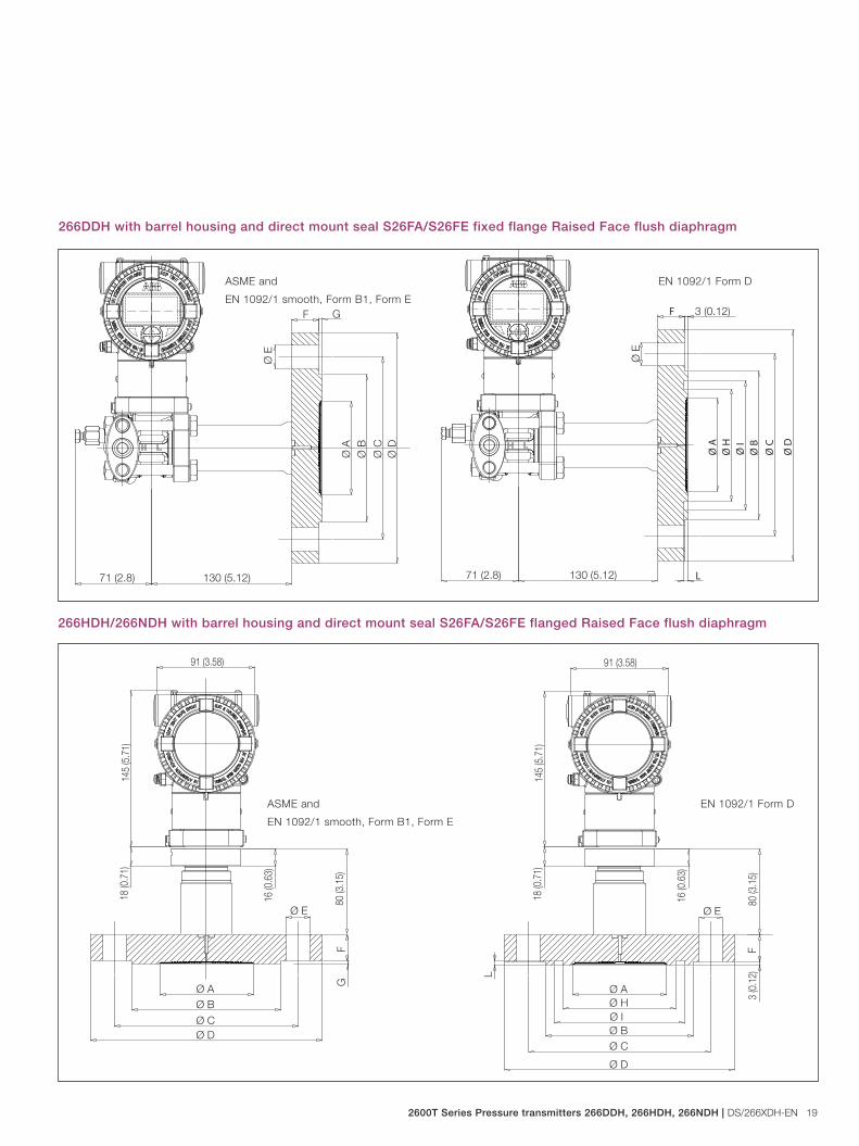
266DDH with barrel housing and direct mount seal S26FA/S26FE fixed flange Raised Face flush diaphragm
266HDH/266NDH with barrel housing and direct mount seal S26FA/S26FE flanged Raised Face flush diaphragm
G
Ø B
Ø D
Ø A
F
71 (2.8) 130 (5.12)
Ø E
Ø C Ø B
Ø D
Ø A
F
71 (2.8) 130 (5.12)
3 (0.12)
Ø E
Ø C
Ø I
Ø H
L
16 (0
.63)
18 (0
.71)
80 (3
.15)
91 (3.58)
145
(5.7
1)
Ø B
Ø D
Ø A
FG
Ø E
Ø CØ B
Ø D
Ø A
Ø C
Ø IØ H
L
F
16 (0
.63)
18 (0
.71)
80 (3
.15)
3 (0
.12)
91 (3.58)
145
(5.7
1)
Ø E
ASME and
EN 1092/1 smooth, Form B1, Form E
EN 1092/1 Form D
ASME and
EN 1092/1 smooth, Form B1, Form E
EN 1092/1 Form D
20 DS/266XDH-EN | 2600T Series Pressure transmitters 266DDH, 266HDH, 266NDH
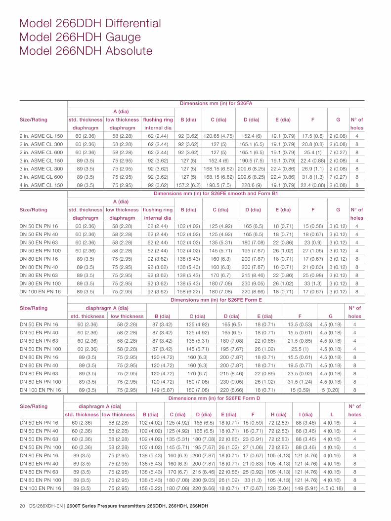
Model 266DDH Differential Model 266HDH Gauge Model 266NDH Absolute
Size/Rating
Dimensions mm (in) for S26FA
A (dia)
B (dia) C (dia) D (dia) E (dia) F G N° of
holes
std. thickness
diaphragm
low thickness
diaphragm
flushing ring
internal dia
2 in. ASME CL 150 60 (2.36) 58 (2.28) 62 (2.44) 92 (3.62) 120.65 (4.75) 152.4 (6) 19.1 (0.79) 17.5 (0.6) 2 (0.08) 4
2 in. ASME CL 300 60 (2.36) 58 (2.28) 62 (2.44) 92 (3.62) 127 (5) 165.1 (6.5) 19.1 (0.79) 20.8 (0.8) 2 (0.08) 8
2 in. ASME CL 600 60 (2.36) 58 (2.28) 62 (2.44) 92 (3.62) 127 (5) 165.1 (6.5) 19.1 (0.79) 25.4 (1) 7 (0.27) 8
3 in. ASME CL 150 89 (3.5) 75 (2.95) 92 (3.62) 127 (5) 152.4 (6) 190.5 (7.5) 19.1 (0.79) 22.4 (0.88) 2 (0.08) 4
3 in. ASME CL 300 89 (3.5) 75 (2.95) 92 (3.62) 127 (5) 168.15 (6.62) 209.6 (8.25) 22.4 (0.86) 26.9 (1.1) 2 (0.08) 8
3 in. ASME CL 600 89 (3.5) 75 (2.95) 92 (3.62) 127 (5) 168.15 (6.62) 209.6 (8.25) 22.4 (0.86) 31.8 (1.3) 7 (0.27) 8
4 in. ASME CL 150 89 (3.5) 75 (2.95) 92 (3.62) 157.2 (6.2) 190.5 (7.5) 228.6 (9) 19.1 (0.79) 22.4 (0.88) 2 (0.08) 8
Size/Rating
Dimensions mm (in) for S26FE smooth and Form B1
A (dia)
B (dia) C (dia) D (dia) E (dia) F G N° of
holes
std. thickness
diaphragm
low thickness
diaphragm
flushing ring
internal dia
DN 50 EN PN 16 60 (2.36) 58 (2.28) 62 (2.44) 102 (4.02) 125 (4.92) 165 (6.5) 18 (0.71) 15 (0.58) 3 (0.12) 4
DN 50 EN PN 40 60 (2.36) 58 (2.28) 62 (2.44) 102 (4.02) 125 (4.92) 165 (6.5) 18 (0.71) 18 (0.67) 3 (0.12) 4
DN 50 EN PN 63 60 (2.36) 58 (2.28) 62 (2.44) 102 (4.02) 135 (5.31) 180 (7.08) 22 (0.86) 23 (0.9) 3 (0.12) 4
DN 50 EN PN 100 60 (2.36) 58 (2.28) 62 (2.44) 102 (4.02) 145 (5.71) 195 (7.67) 26 (1.02) 27 (1.06) 3 (0.12) 4
DN 80 EN PN 16 89 (3.5) 75 (2.95) 92 (3.62) 138 (5.43) 160 (6.3) 200 (7.87) 18 (0.71) 17 (0.67) 3 (0.12) 8
DN 80 EN PN 40 89 (3.5) 75 (2.95) 92 (3.62) 138 (5.43) 160 (6.3) 200 (7.87) 18 (0.71) 21 (0.83) 3 (0.12) 8
DN 80 EN PN 63 89 (3.5) 75 (2.95) 92 (3.62) 138 (5.43) 170 (6.7) 215 (8.46) 22 (0.86) 25 (0.98) 3 (0.12) 8
DN 80 EN PN 100 89 (3.5) 75 (2.95) 92 (3.62) 138 (5.43) 180 (7.08) 230 (9.05) 26 (1.02) 33 (1.3) 3 (0.12) 8
DN 100 EN PN 16 89 (3.5) 75 (2.95) 92 (3.62) 158 (6.22) 180 (7.08) 220 (8.66) 18 (0.71) 17 (0.67) 3 (0.12) 8
Size/Rating
Dimensions mm (in) for S26FE Form E
diaphragm A (dia)
B (dia) C (dia) D (dia) E (dia) F G
N° of
holesstd. thickness low thickness
DN 50 EN PN 16 60 (2.36) 58 (2.28) 87 (3.42) 125 (4.92) 165 (6.5) 18 (0.71) 13.5 (0.53) 4.5 (0.18) 4
DN 50 EN PN 40 60 (2.36) 58 (2.28) 87 (3.42) 125 (4.92) 165 (6.5) 18 (0.71) 15.5 (0.61) 4.5 (0.18) 4
DN 50 EN PN 63 60 (2.36) 58 (2.28) 87 (3.42) 135 (5.31) 180 (7.08) 22 (0.86) 21.5 (0.85) 4.5 (0.18) 4
DN 50 EN PN 100 60 (2.36) 58 (2.28) 87 (3.42) 145 (5.71) 195 (7.67) 26 (1.02) 25.5 (1) 4.5 (0.18) 4
DN 80 EN PN 16 89 (3.5) 75 (2.95) 120 (4.72) 160 (6.3) 200 (7.87) 18 (0.71) 15.5 (0.61) 4.5 (0.18) 8
DN 80 EN PN 40 89 (3.5) 75 (2.95) 120 (4.72) 160 (6.3) 200 (7.87) 18 (0.71) 19.5 (0.77) 4.5 (0.18) 8
DN 80 EN PN 63 89 (3.5) 75 (2.95) 120 (4.72) 170 (6.7) 215 (8.46) 22 (0.86) 23.5 (0.92) 4.5 (0.18) 8
DN 80 EN PN 100 89 (3.5) 75 (2.95) 120 (4.72) 180 (7.08) 230 (9.05) 26 (1.02) 31.5 (1.24) 4.5 (0.18) 8
DN 100 EN PN 16 89 (3.5) 75 (2.95) 149 (5.87) 180 (7.08) 220 (8.66) 18 (0.71) 15 (0.59) 5 (0.20) 8
Size/Rating
Dimensions mm (in) for S26FE Form D
diaphragm A (dia)
B (dia) C (dia) D (dia) E (dia) F H (dia) I (dia) L
N° of
holesstd. thickness low thickness
DN 50 EN PN 16 60 (2.36) 58 (2.28) 102 (4.02) 125 (4.92) 165 (6.5) 18 (0.71) 15 (0.59) 72 (2.83) 88 (3.46) 4 (0.16) 4
DN 50 EN PN 40 60 (2.36) 58 (2.28) 102 (4.02) 125 (4.92) 165 (6.5) 18 (0.71) 18 (0.71) 72 (2.83) 88 (3.46) 4 (0.16) 4
DN 50 EN PN 63 60 (2.36) 58 (2.28) 102 (4.02) 135 (5.31) 180 (7.08) 22 (0.86) 23 (0.91) 72 (2.83) 88 (3.46) 4 (0.16) 4
DN 50 EN PN 100 60 (2.36) 58 (2.28) 102 (4.02) 145 (5.71) 195 (7.67) 26 (1.02) 27 (1.06) 72 (2.83) 88 (3.46) 4 (0.16) 4
DN 80 EN PN 16 89 (3.5) 75 (2.95) 138 (5.43) 160 (6.3) 200 (7.87) 18 (0.71) 17 (0.67) 105 (4.13) 121 (4.76) 4 (0.16) 8
DN 80 EN PN 40 89 (3.5) 75 (2.95) 138 (5.43) 160 (6.3) 200 (7.87) 18 (0.71) 21 (0.83) 105 (4.13) 121 (4.76) 4 (0.16) 8
DN 80 EN PN 63 89 (3.5) 75 (2.95) 138 (5.43) 170 (6.7) 215 (8.46) 22 (0.86) 25 (0.92) 105 (4.13) 121 (4.76) 4 (0.16) 8
DN 80 EN PN 100 89 (3.5) 75 (2.95) 138 (5.43) 180 (7.08) 230 (9.05) 26 (1.02) 33 (1.3) 105 (4.13) 121 (4.76) 4 (0.16) 8
DN 100 EN PN 16 89 (3.5) 75 (2.95) 158 (6.22) 180 (7.08) 220 (8.66) 18 (0.71) 17 (0.67) 128 (5.04) 149 (5.91) 4.5 (0.18) 8
2600T Series Pressure transmitters 266DDH, 266HDH, 266NDH | DS/266XDH-EN 21
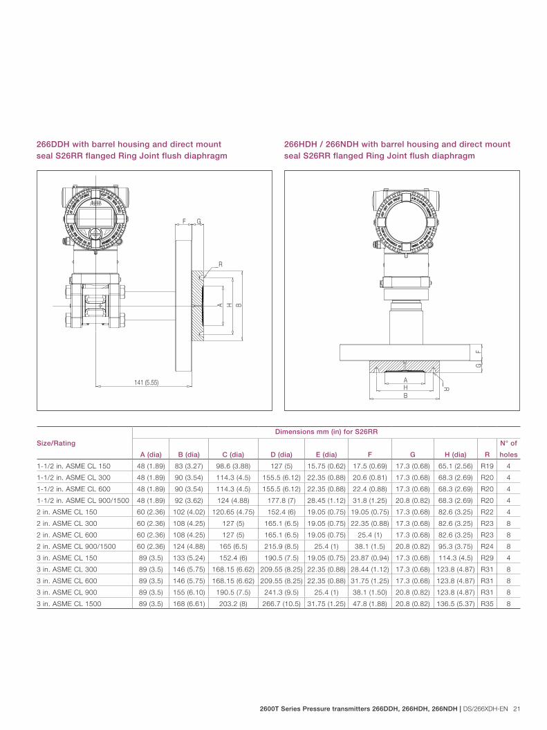
266DDH with barrel housing and direct mount seal S26RR flanged Ring Joint flush diaphragm
266HDH / 266NDH with barrel housing and direct mount seal S26RR flanged Ring Joint flush diaphragm
141 (5.55)
A BHF G
R
A
BH
FG
R
Size/Rating
Dimensions mm (in) for S26RR
A (dia) B (dia) C (dia) D (dia) E (dia) F G H (dia) R
N° of
holes
1-1/2 in. ASME CL 150 48 (1.89) 83 (3.27) 98.6 (3.88) 127 (5) 15.75 (0.62) 17.5 (0.69) 17.3 (0.68) 65.1 (2.56) R19 4
1-1/2 in. ASME CL 300 48 (1.89) 90 (3.54) 114.3 (4.5) 155.5 (6.12) 22.35 (0.88) 20.6 (0.81) 17.3 (0.68) 68.3 (2.69) R20 4
1-1/2 in. ASME CL 600 48 (1.89) 90 (3.54) 114.3 (4.5) 155.5 (6.12) 22.35 (0.88) 22.4 (0.88) 17.3 (0.68) 68.3 (2.69) R20 4
1-1/2 in. ASME CL 900/1500 48 (1.89) 92 (3.62) 124 (4.88) 177.8 (7) 28.45 (1.12) 31.8 (1.25) 20.8 (0.82) 68.3 (2.69) R20 4
2 in. ASME CL 150 60 (2.36) 102 (4.02) 120.65 (4.75) 152.4 (6) 19.05 (0.75) 19.05 (0.75) 17.3 (0.68) 82.6 (3.25) R22 4
2 in. ASME CL 300 60 (2.36) 108 (4.25) 127 (5) 165.1 (6.5) 19.05 (0.75) 22.35 (0.88) 17.3 (0.68) 82.6 (3.25) R23 8
2 in. ASME CL 600 60 (2.36) 108 (4.25) 127 (5) 165.1 (6.5) 19.05 (0.75) 25.4 (1) 17.3 (0.68) 82.6 (3.25) R23 8
2 in. ASME CL 900/1500 60 (2.36) 124 (4.88) 165 (6.5) 215.9 (8.5) 25.4 (1) 38.1 (1.5) 20.8 (0.82) 95.3 (3.75) R24 8
3 in. ASME CL 150 89 (3.5) 133 (5.24) 152.4 (6) 190.5 (7.5) 19.05 (0.75) 23.87 (0.94) 17.3 (0.68) 114.3 (4.5) R29 4
3 in. ASME CL 300 89 (3.5) 146 (5.75) 168.15 (6.62) 209.55 (8.25) 22.35 (0.88) 28.44 (1.12) 17.3 (0.68) 123.8 (4.87) R31 8
3 in. ASME CL 600 89 (3.5) 146 (5.75) 168.15 (6.62) 209.55 (8.25) 22.35 (0.88) 31.75 (1.25) 17.3 (0.68) 123.8 (4.87) R31 8
3 in. ASME CL 900 89 (3.5) 155 (6.10) 190.5 (7.5) 241.3 (9.5) 25.4 (1) 38.1 (1.50) 20.8 (0.82) 123.8 (4.87) R31 8
3 in. ASME CL 1500 89 (3.5) 168 (6.61) 203.2 (8) 266.7 (10.5) 31.75 (1.25) 47.8 (1.88) 20.8 (0.82) 136.5 (5.37) R35 8
22 DS/266XDH-EN | 2600T Series Pressure transmitters 266DDH, 266HDH, 266NDH
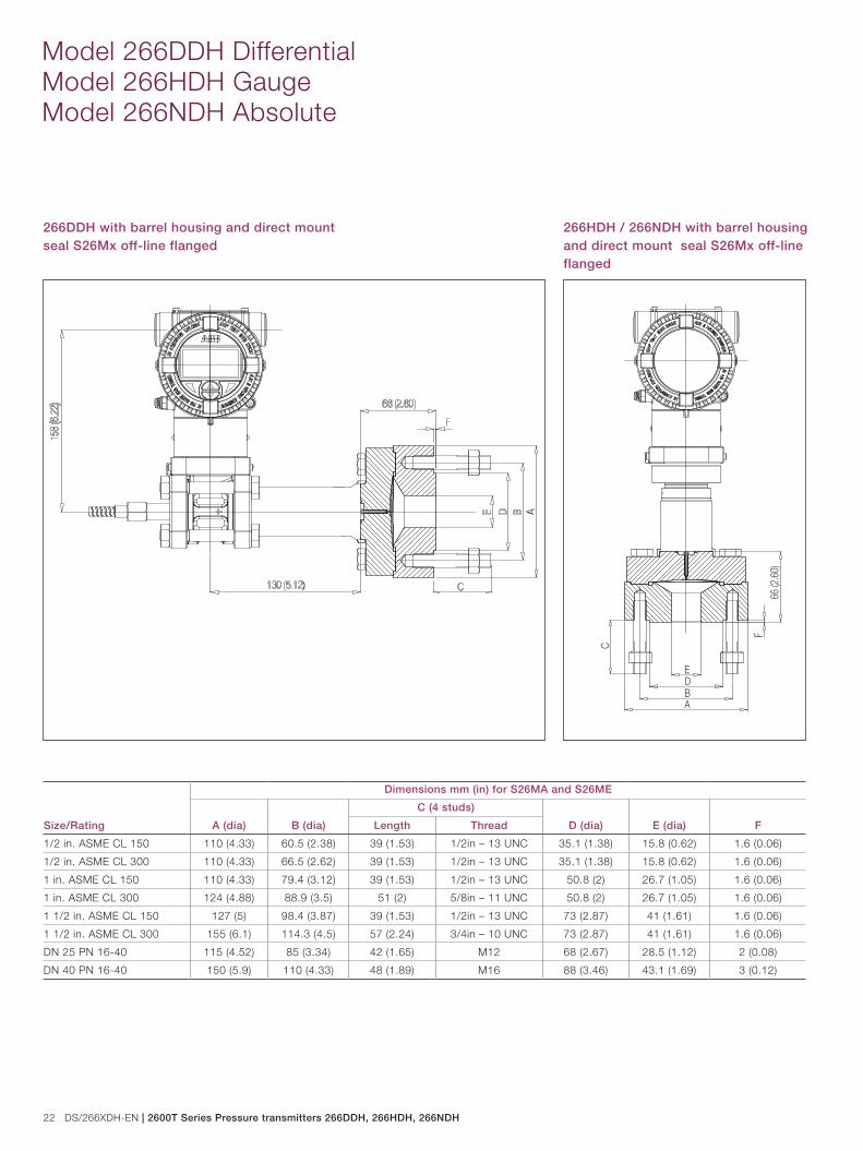
Model 266DDH Differential Model 266HDH Gauge Model 266NDH Absolute
266DDH with barrel housing and direct mount seal S26Mx off-line flanged
266HDH / 266NDH with barrel housing and direct mount seal S26Mx off-line flanged
Size/Rating
Dimensions mm (in) for S26MA and S26ME
A (dia) B (dia)
C (4 studs)
D (dia) E (dia) FLength Thread
1/2 in. ASME CL 150 110 (4.33) 60.5 (2.38) 39 (1.53) 1/2in – 13 UNC 35.1 (1.38) 15.8 (0.62) 1.6 (0.06)
1/2 in. ASME CL 300 110 (4.33) 66.5 (2.62) 39 (1.53) 1/2in – 13 UNC 35.1 (1.38) 15.8 (0.62) 1.6 (0.06)
1 in. ASME CL 150 110 (4.33) 79.4 (3.12) 39 (1.53) 1/2in – 13 UNC 50.8 (2) 26.7 (1.05) 1.6 (0.06)
1 in. ASME CL 300 124 (4.88) 88.9 (3.5) 51 (2) 5/8in – 11 UNC 50.8 (2) 26.7 (1.05) 1.6 (0.06)
1 1/2 in. ASME CL 150 127 (5) 98.4 (3.87) 39 (1.53) 1/2in – 13 UNC 73 (2.87) 41 (1.61) 1.6 (0.06)
1 1/2 in. ASME CL 300 155 (6.1) 114.3 (4.5) 57 (2.24) 3/4in – 10 UNC 73 (2.87) 41 (1.61) 1.6 (0.06)
DN 25 PN 16-40 115 (4.52) 85 (3.34) 42 (1.65) M12 68 (2.67) 28.5 (1.12) 2 (0.08)
DN 40 PN 16-40 150 (5.9) 110 (4.33) 48 (1.89) M16 88 (3.46) 43.1 (1.69) 3 (0.12)
A
F66
(2.6
0)
C
BDE
2600T Series Pressure transmitters 266DDH, 266HDH, 266NDH | DS/266XDH-EN 23
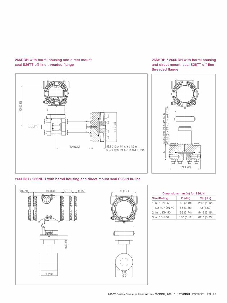
266DDH with barrel housing and direct mount seal S26TT off-line threaded flange
266HDH / 266NDH with barrel housing and direct mount seal S26TT off-line threaded flange
Dimensions mm (in) for S26JN
Size/Rating D (dia) Mb (dia)
1 in. / DN 25 63 (2.48) 28.5 (1.12)
1 1/2 in. / DN 40 85 (3.35) 43 (1.69)
2 in. / DN 50 95 (3.74) 54.5 (2.15)
3 in. / DN 80 130 (5.12) 82.5 (3.25)
Q53
.3 (2
.1) f
or 1
/4 in
. and
1/2
in.
63.5
(2.5
) for
3/4
in.,
1 in.
and
1 1
/2 in
.109.2 (4.3)
53.3 (2.1) for 1/4 in. and 1/2 in.63.5 (2.5) for 3/4 in., 1 in. and 1 1/2 in.
109.
2 (4
.3)
130 (5.12)
158
(6.2
2)
266HDH / 266NDH with barrel housing and direct mount seal S26JN in-line
16 (0
.63)
18 (0.71)18 (0.71) 110 (4.33) 29 (1.14) 91 (3.58)
Ø MbØ D60 (2.36)
24 DS/266XDH-EN | 2600T Series Pressure transmitters 266DDH, 266HDH, 266NDH
Model 266DDH Differential Model 266HDH Gauge Model 266NDH Absolute
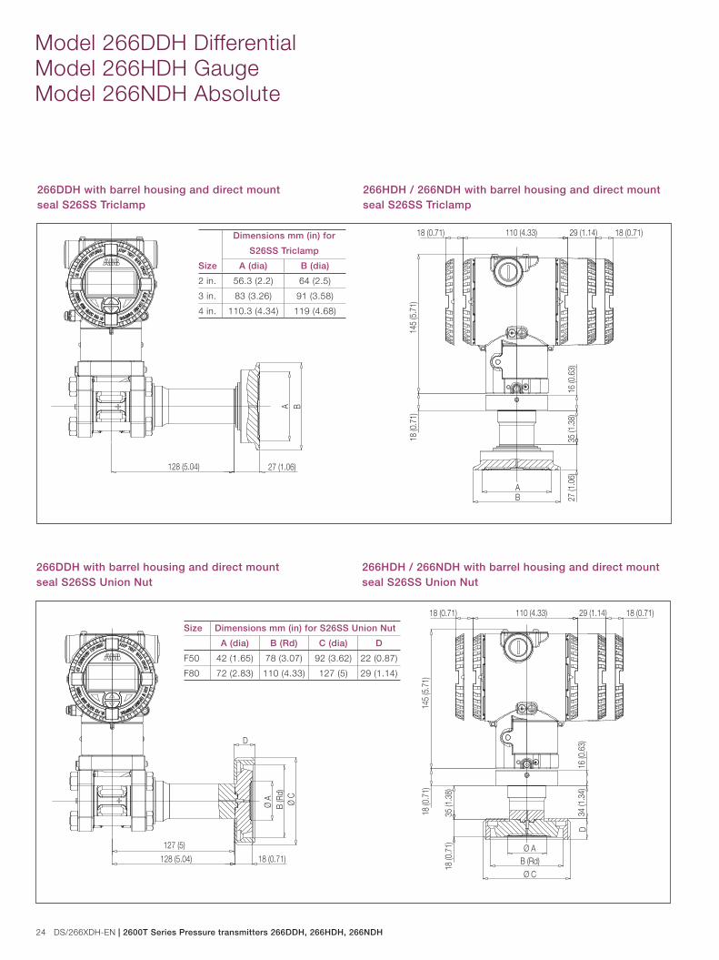
128 (5.04)
BA
27 (1.06)
266DDH with barrel housing and direct mount seal S26SS Triclamp
266HDH / 266NDH with barrel housing and direct mount seal S26SS Triclamp
Size
Dimensions mm (in) for
S26SS Triclamp
A (dia) B (dia)
2 in. 56.3 (2.2) 64 (2.5)
3 in. 83 (3.26) 91 (3.58)
4 in. 110.3 (4.34) 119 (4.68)
16 (0
.63)
18 (0.71)
18 (0
.71)
18 (0.71) 110 (4.33) 29 (1.14)
145
(5.7
1)
35 (1
.38)
27 (1
.06)
AB
266DDH with barrel housing and direct mount seal S26SS Union Nut
266HDH / 266NDH with barrel housing and direct mount seal S26SS Union Nut
128 (5.04)
Ø C
Ø A
B (R
d)
D
18 (0.71)
127 (5)
16 (0
.63)
18 (0.71)
18 (0
.71)
18 (0.71) 110 (4.33) 29 (1.14)
145
(5.7
1)
Ø AB (Rd)
D34
(1.3
4)
35 (1
.38)
18 (0
.71)
Ø C
Size Dimensions mm (in) for S26SS Union Nut
A (dia) B (Rd) C (dia) D
F50 42 (1.65) 78 (3.07) 92 (3.62) 22 (0.87)
F80 72 (2.83) 110 (4.33) 127 (5) 29 (1.14)
2600T Series Pressure transmitters 266DDH, 266HDH, 266NDH | DS/266XDH-EN 25
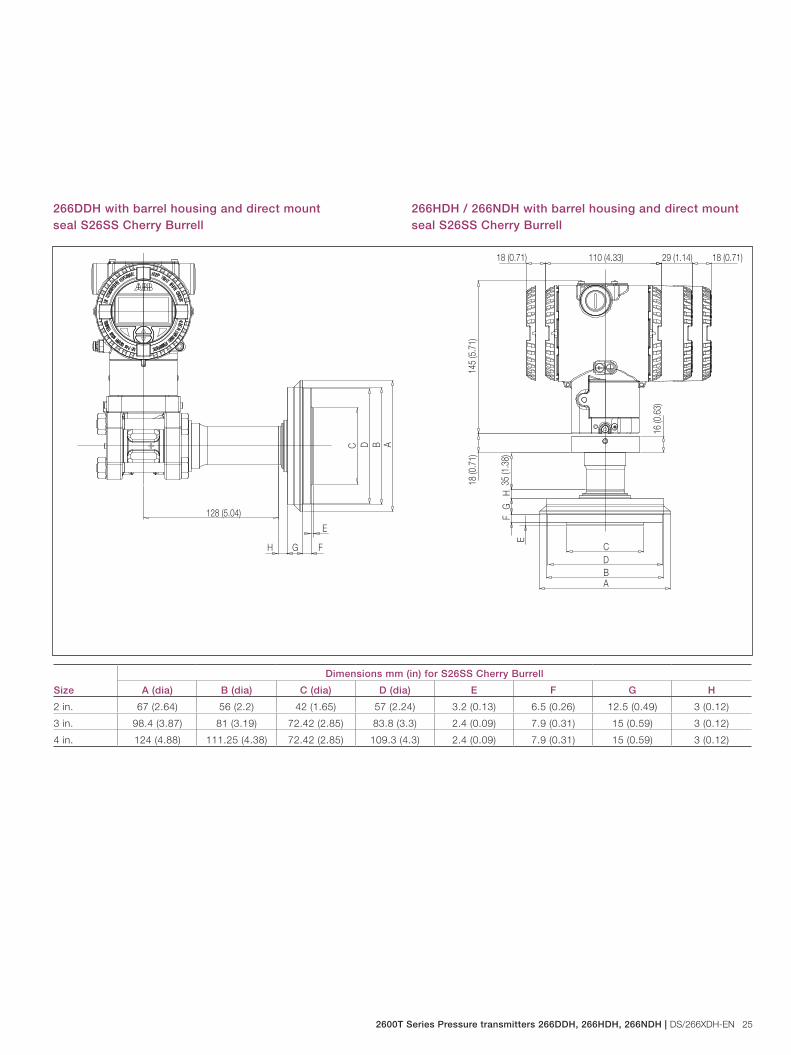
266DDH with barrel housing and direct mount seal S26SS Cherry Burrell
266HDH / 266NDH with barrel housing and direct mount seal S26SS Cherry Burrell
128 (5.04)
C D A
E
FGH
B
16 (0
.63)
18 (0.71)
18 (0
.71)
18 (0.71) 110 (4.33) 29 (1.14)
145
(5.7
1)
A
DC
B
EF
GH
35 (1
.38)
Size
Dimensions mm (in) for S26SS Cherry Burrell
A (dia) B (dia) C (dia) D (dia) E F G H
2 in. 67 (2.64) 56 (2.2) 42 (1.65) 57 (2.24) 3.2 (0.13) 6.5 (0.26) 12.5 (0.49) 3 (0.12)
3 in. 98.4 (3.87) 81 (3.19) 72.42 (2.85) 83.8 (3.3) 2.4 (0.09) 7.9 (0.31) 15 (0.59) 3 (0.12)
4 in. 124 (4.88) 111.25 (4.38) 72.42 (2.85) 109.3 (4.3) 2.4 (0.09) 7.9 (0.31) 15 (0.59) 3 (0.12)
26 DS/266XDH-EN | 2600T Series Pressure transmitters 266DDH, 266HDH, 266NDH
Model 266DDH Differential Model 266HDH Gauge Model 266NDH Absolute
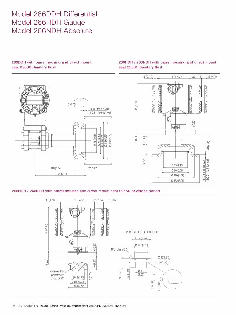
266DDH with barrel housing and direct mount seal S26SS Sanitary flush
266HDH / 266NDH with barrel housing and direct mount seal S26SS Sanitary flush
22 (0.87)
Ø 1
52 (5
.98)
Ø 7
5 (2
.95)
Ø 1
19 (4
.69)
8 (0.31) for thin wall
Ø 8
6 (3
.39)
13 (0.51) for thick wall
128 (5.04)
163 (6.42)
Ø 1
18 (4
.65)
32 (1.26)
19 (0.75)
16 (0
.63)
18 (0.71)
18 (0
.71)
18 (0.71) 110 (4.33) 29 (1.14)
145
(5.7
1)
35 (1
.38)
22 (0
.87)
70 (2
.76)
Ø 152 (5.98)
Ø 75 (2.95)
Ø 119 (4.69)
8 (0
.31)
for t
hin w
all
Ø 86 (3.39)
13 (0
.51)
for t
hick
wall
266HDH / 266NDH with barrel housing and direct mount seal S26SS beverage bolted
16 (0
.63)
18 (0.71)
18 (0
.71)
18 (0.71) 110 (4.33) 29 (1.14)
145
(5.7
1)
Ø 52.2 (2.06)Ø 64 (2.52)
Ø 44 (1.73)
Ø 64 (2.52)
Ø 39(1.54)
Ø 34(1.34)
Ø 39.8(1.57)
Ø 52.2(2.06)
40 (1
.57)
5 (0
.20)
36 (1
.42)
12 (0
.47)
4 (0
.16)
1.3
(0.0
6)
N°6 holes Ø 6.5
SPUD FOR BEVERAGE BOLTED
N°6 holes M6simmetrically placed at 60°
2600T Series Pressure transmitters 266DDH, 266HDH, 266NDH | DS/266XDH-EN 27
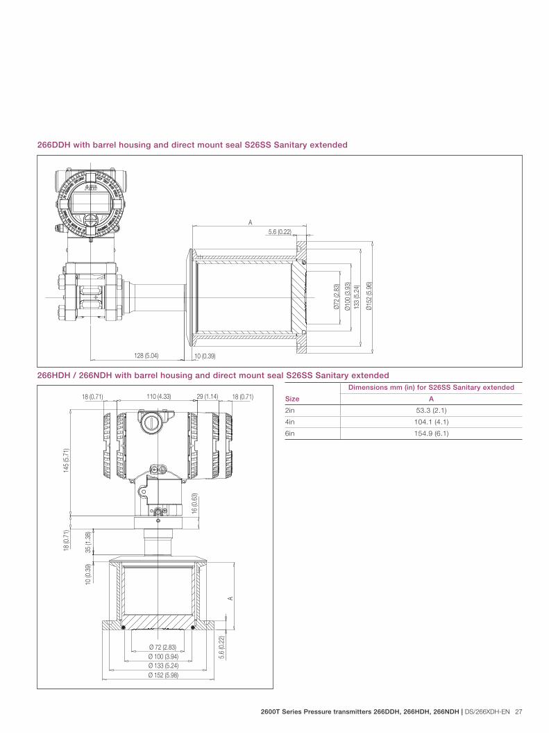
266DDH with barrel housing and direct mount seal S26SS Sanitary extended
266HDH / 266NDH with barrel housing and direct mount seal S26SS Sanitary extended
128 (5.04)
Ø72
(2.8
3)
Ø10
0 (3
.93)
Ø15
2 (5
.96)
5.6 (0.22)A
10 (0.39)13
3 (5
.24)
Size
Dimensions mm (in) for S26SS Sanitary extended
A
2in 53.3 (2.1)
4in 104.1 (4.1)
6in 154.9 (6.1)
16 (0
.63)
18 (0.71)
18 (0
.71)
18 (0.71) 110 (4.33) 29 (1.14)
145
(5.7
1)
35 (1
.38)
Ø 72 (2.83)Ø 100 (3.94)
Ø 152 (5.98)
5.6
(0.2
2)A
10 (0
.39)
Ø 133 (5.24)

28 DS/266XDH-EN | 2600T Series Pressure transmitters 266DDH, 266HDH, 266NDH
Model 266DDH Differential Model 266HDH Gauge Model 266NDH Absolute
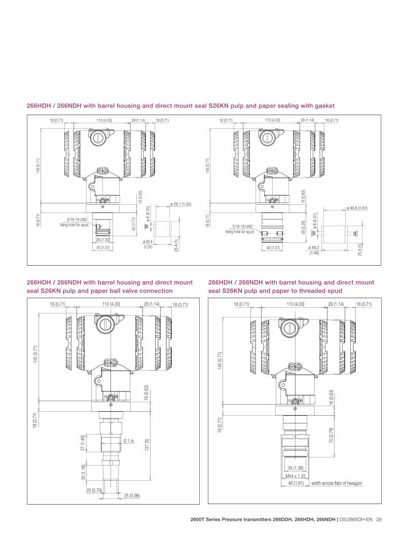
266HDH / 266NDH with barrel housing and direct mount seal S26KN pulp and paper NPT threaded connections
16 (0
.63)
18 (0.71)
18 (0
.71)
18 (0.71)
26 (1.02)
16 (0
.63)
18 (0.71)
18 (0
.71)
18 (0.71)110 (4.33) 29 (1.14)
145
(5.7
1)
110 (4.33) 29 (1.14)
145
(5.7
1)
65 (2
.56)
1 in.-11.5 NPT
66 (2
.6)
39 (1.54)1 1/2 in.-11.5 NPT
41 (1.61) width across flats of hexagon width across flats of hexagon55 (2.17)
266HDH / 266NDH with barrel housing and direct mount seal S26KN pulp and paper Gas threaded connections16
(0.6
3)18 (0.71)
18 (0
.71)
18 (0.71)
16 (0
.63)
18 (0.71)
18 (0
.71)
18 (0.71) 110 (4.33) 29 (1.14)
145
(5.7
1)
110 (4.33) 29 (1.14)
145
(5.7
1)
63 (2
.48)
39 (1.54)G 1 1/2 in. AG 1 in. A
26 (1.02)
61 (2
.4)
41 (1.61) width across flats of hexagon width across flats of hexagon55 (2.17)
2600T Series Pressure transmitters 266DDH, 266HDH, 266NDH | DS/266XDH-EN 29
266HDH / 266NDH with barrel housing and direct mount seal S26KN pulp and paper sealing with gasket
16 (0
.63)
18 (0.71)
18 (0
.71)
18 (0.71)
5/16-18 UNC fixing hole for spud
110 (4.33) 29 (1.14)
145
(5.7
1)
45 (1
.77)
26 (1.02)
40 (1.57)
16 (0
.63)
18 (0.71)
18 (0
.71)
18 (0.71)
5/16-18 UNC fixing hole for spud
110 (4.33) 29 (1.14)
145
(5.7
1)
58 (2
.28)
40 (1.57)
25.4
(1)
ø 26.7 (1.05)
ø 33.4 (1.31)
ø 8
(0.3
1)
25.4
(1)
ø 40.8 (1.61)
ø 48.2 (1.90)
ø 8
(0.3
1)
266HDH / 266NDH with barrel housing and direct mount seal S26KN pulp and paper ball valve connection
16 (0
.63)
18 (0.71)
18 (0
.71)
18 (0.71)
127
(5)
20 (0.79)25 (0.98)
37 (1
.46)
30 (1
.18)
G 1 in.
110 (4.33) 29 (1.14)
145
(5.7
1)
266HDH / 266NDH with barrel housing and direct mount seal S26KN pulp and paper to threaded spud
16 (0
.63)
18 (0.71)
18 (0
.71)
18 (0.71)
70 (2
.76)
M44 x 1.25
35 (1.38)
110 (4.33) 29 (1.14)
145
(5.7
1)
46 (1.81) width across flats of hexagon
30 DS/266XDH-EN | 2600T Series Pressure transmitters 266DDH, 266HDH, 266NDH
Model 266DDH Differential Model 266HDH Gauge Model 266NDH Absolute
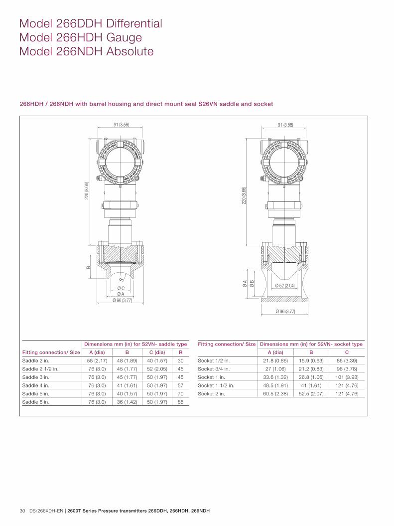
266HDH / 266NDH with barrel housing and direct mount seal S26VN saddle and socket
R
Ø C
Ø 96 (3.77)Ø A
B
91 (3.58)
220
(8.6
6)
Ø A Ø B
Ø 96 (3.77)
Ø 52 (2.04)
91 (3.58)
220
(8.6
6)
Fitting connection/ Size
Dimensions mm (in) for S2VN- saddle type
A (dia) B C (dia) R
Saddle 2 in. 55 (2.17) 48 (1.89) 40 (1.57) 30
Saddle 2 1/2 in. 76 (3.0) 45 (1.77) 52 (2.05) 45
Saddle 3 in. 76 (3.0) 45 (1.77) 50 (1.97) 45
Saddle 4 in. 76 (3.0) 41 (1.61) 50 (1.97) 57
Saddle 5 in. 76 (3.0) 40 (1.57) 50 (1.97) 70
Saddle 6 in. 76 (3.0) 36 (1.42) 50 (1.97) 85
Fitting connection/ Size Dimensions mm (in) for S2VN- socket type
A (dia) B C
Socket 1/2 in. 21.8 (0.86) 15.9 (0.63) 86 (3.39)
Socket 3/4 in. 27 (1.06) 21.2 (0.83) 96 (3.78)
Socket 1 in. 33.6 (1.32) 26.8 (1.06) 101 (3.98)
Socket 1 1/2 in. 48.5 (1.91) 41 (1.61) 121 (4.76)
Socket 2 in. 60.5 (2.38) 52.5 (2.07) 121 (4.76)
2600T Series Pressure transmitters 266DDH, 266HDH, 266NDH | DS/266XDH-EN 31
+
-+
+
- -
+M
-Kent-Taylor
0
435 6 7 8
910
2040
0
60100%
2 80
691HT
A B C
1D E F
2G H I
3
J K L
4M N O
5P Q R
6
S T U
7V W X
8Y Z #
9
@ % & /0
+-
PV
REVIE W SERIALLINK
TRI M
F1 F2 F3 F4
CONF
-
21
+
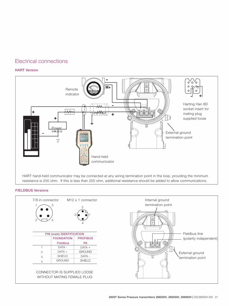
Electrical connections
HART Version
FIELDBUS Versions
Internal groundtermination point
Fieldbus line(polarity independent)
External groundtermination point
HART hand-held communicator may be connected at any wiring termination point in the loop, providing the minimum resistance is 250 ohm. If this is less than 250 ohm, additional resistance should be added to allow communications.
7/8 in connector M12 x 1 connector
CONNECTOR IS SUPPLIED LOOSE WITHOUT MATING FEMALE PLUG
External groundtermination point
Hand-heldcommunicator
Powersource
Line load
Remoteindicator
2
1
4
3
1 3
42
PIN (male) IDENTIFICATION
FOUNDATION
Fieldbus
PROFIBUS
PA
1
2
3
4
DATA - DATA +DATA + GROUNDSHIELD DATA -
GROUND SHIELD
Harting Han 8Dsocket insert formating plug supplied loose
2
1
4
3
1 3
42
32 DS/266XDH-EN | 2600T Series Pressure transmitters 266DDH, 266HDH, 266NDH
Model 266DDH Differential Model 266HDH Gauge Model 266NDH Absolute
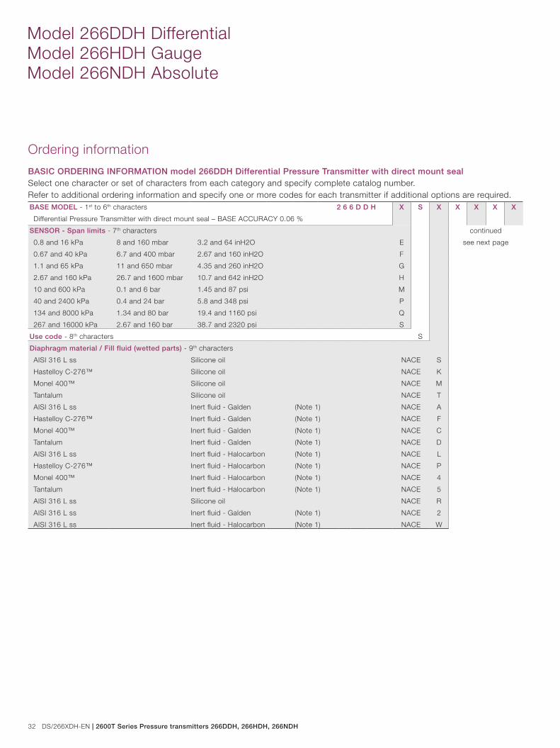
Ordering information
BASIC ORDERING INFORMATION model 266DDH Differential Pressure Transmitter with direct mount sealSelect one character or set of characters from each category and specify complete catalog number.Refer to additional ordering information and specify one or more codes for each transmitter if additional options are required.BASE MODEL - 1st to 6th characters 2 6 6 D D H X S X X X X X
Differential Pressure Transmitter with direct mount seal – BASE ACCURACY 0.06 %
SENSOR - Span limits - 7th characters continued
see next page0.8 and 16 kPa 8 and 160 mbar 3.2 and 64 inH2O E
0.67 and 40 kPa 6.7 and 400 mbar 2.67 and 160 inH2O F
1.1 and 65 kPa 11 and 650 mbar 4.35 and 260 inH2O G
2.67 and 160 kPa 26.7 and 1600 mbar 10.7 and 642 inH2O H
10 and 600 kPa 0.1 and 6 bar 1.45 and 87 psi M
40 and 2400 kPa 0.4 and 24 bar 5.8 and 348 psi P
134 and 8000 kPa 1.34 and 80 bar 19.4 and 1160 psi Q
267 and 16000 kPa 2.67 and 160 bar 38.7 and 2320 psi S
Use code - 8th characters S
Diaphragm material / Fill fluid (wetted parts) - 9th characters
AISI 316 L ss Silicone oil NACE S
Hastelloy C-276™ Silicone oil NACE K
Monel 400™ Silicone oil NACE M
Tantalum Silicone oil NACE T
AISI 316 L ss Inert fluid - Galden (Note 1) NACE A
Hastelloy C-276™ Inert fluid - Galden (Note 1) NACE F
Monel 400™ Inert fluid - Galden (Note 1) NACE C
Tantalum Inert fluid - Galden (Note 1) NACE D
AISI 316 L ss Inert fluid - Halocarbon (Note 1) NACE L
Hastelloy C-276™ Inert fluid - Halocarbon (Note 1) NACE P
Monel 400™ Inert fluid - Halocarbon (Note 1) NACE 4
Tantalum Inert fluid - Halocarbon (Note 1) NACE 5
AISI 316 L ss Silicone oil NACE R
AISI 316 L ss Inert fluid - Galden (Note 1) NACE 2
AISI 316 L ss Inert fluid - Halocarbon (Note 1) NACE W
2600T Series Pressure transmitters 266DDH, 266HDH, 266NDH | DS/266XDH-EN 33
BASIC ORDERING INFORMATION model 266DDH Differential Pressure Transmitter 2 6 6 D D H X S X X X X X
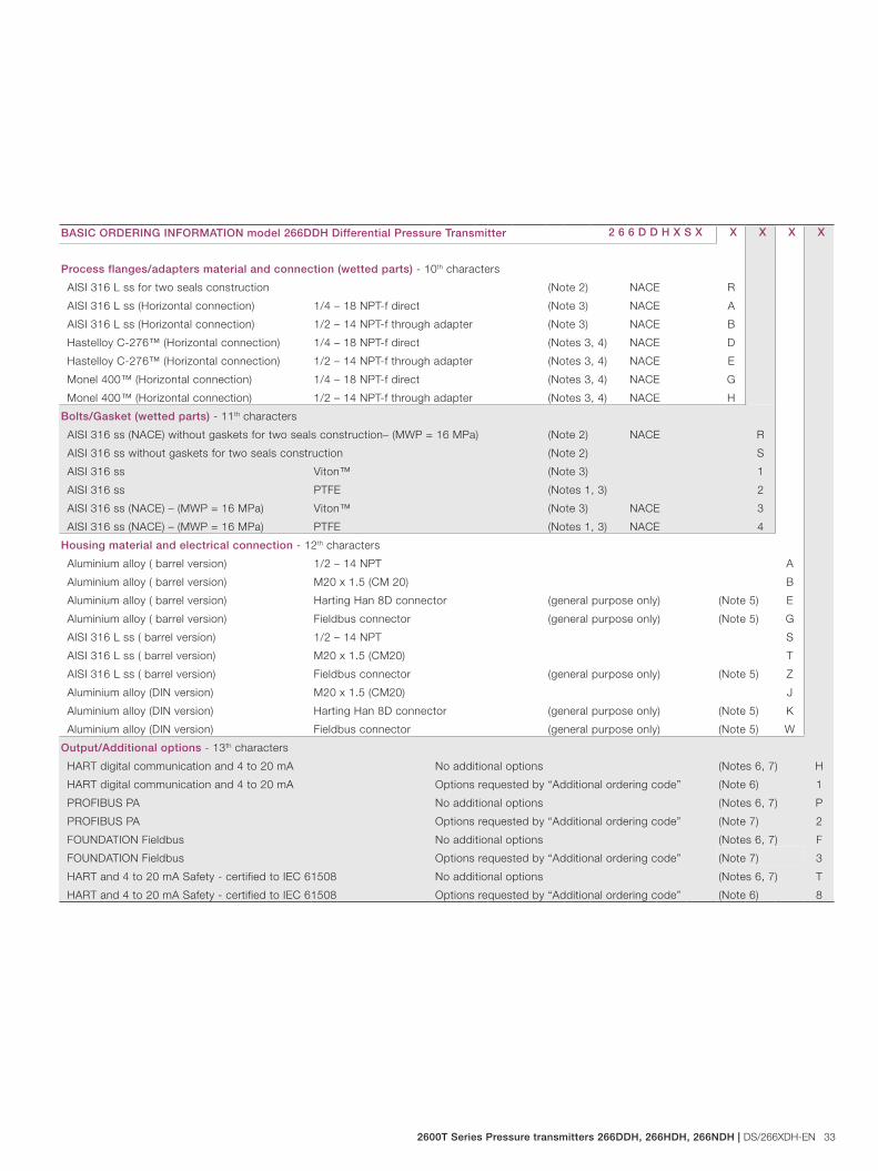
Process flanges/adapters material and connection (wetted parts) - 10th characters
AISI 316 L ss for two seals construction (Note 2) NACE R
AISI 316 L ss (Horizontal connection) 1/4 – 18 NPT-f direct (Note 3) NACE A
AISI 316 L ss (Horizontal connection) 1/2 – 14 NPT-f through adapter (Note 3) NACE B
Hastelloy C-276™ (Horizontal connection) 1/4 – 18 NPT-f direct (Notes 3, 4) NACE D
Hastelloy C-276™ (Horizontal connection) 1/2 – 14 NPT-f through adapter (Notes 3, 4) NACE E
Monel 400™ (Horizontal connection) 1/4 – 18 NPT-f direct (Notes 3, 4) NACE G
Monel 400™ (Horizontal connection) 1/2 – 14 NPT-f through adapter (Notes 3, 4) NACE H
Bolts/Gasket (wetted parts) - 11th characters
AISI 316 ss (NACE) without gaskets for two seals construction– (MWP = 16 MPa) (Note 2) NACE R
AISI 316 ss without gaskets for two seals construction (Note 2) S
AISI 316 ss Viton™ (Note 3) 1
AISI 316 ss PTFE (Notes 1, 3) 2
AISI 316 ss (NACE) – (MWP = 16 MPa) Viton™ (Note 3) NACE 3
AISI 316 ss (NACE) – (MWP = 16 MPa) PTFE (Notes 1, 3) NACE 4
Housing material and electrical connection - 12th characters
Aluminium alloy ( barrel version) 1/2 – 14 NPT A
Aluminium alloy ( barrel version) M20 x 1.5 (CM 20) B
Aluminium alloy ( barrel version) Harting Han 8D connector (general purpose only) (Note 5) E
Aluminium alloy ( barrel version) Fieldbus connector (general purpose only) (Note 5) G
AISI 316 L ss ( barrel version) 1/2 – 14 NPT S
AISI 316 L ss ( barrel version) M20 x 1.5 (CM20) T
AISI 316 L ss ( barrel version) Fieldbus connector (general purpose only) (Note 5) Z
Aluminium alloy (DIN version) M20 x 1.5 (CM20) J
Aluminium alloy (DIN version) Harting Han 8D connector (general purpose only) (Note 5) K
Aluminium alloy (DIN version) Fieldbus connector (general purpose only) (Note 5) W
Output/Additional options - 13th characters
HART digital communication and 4 to 20 mA No additional options (Notes 6, 7) H
HART digital communication and 4 to 20 mA Options requested by “Additional ordering code” (Note 6) 1
PROFIBUS PA No additional options (Notes 6, 7) P
PROFIBUS PA Options requested by “Additional ordering code” (Note 7) 2
FOUNDATION Fieldbus No additional options (Notes 6, 7) F
FOUNDATION Fieldbus Options requested by “Additional ordering code” (Note 7) 3
HART and 4 to 20 mA Safety - certified to IEC 61508 No additional options (Notes 6, 7) T
HART and 4 to 20 mA Safety - certified to IEC 61508 Options requested by “Additional ordering code” (Note 6) 8
34 DS/266XDH-EN | 2600T Series Pressure transmitters 266DDH, 266HDH, 266NDH
Model 266DDH Differential Model 266HDH Gauge Model 266NDH Absolute
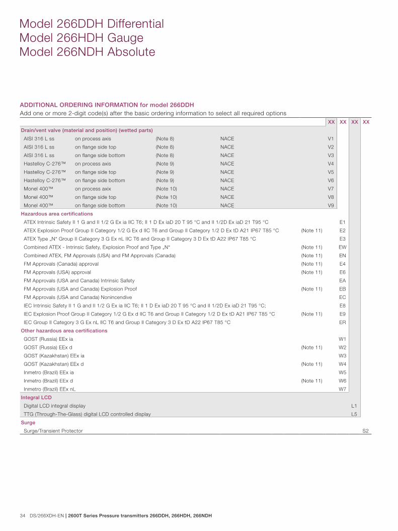
ADDITIONAL ORDERING INFORMATION for model 266DDHAdd one or more 2-digit code(s) after the basic ordering information to select all required options
XX XX XX XX
Drain/vent valve (material and position) (wetted parts)
AISI 316 L ss on process axis (Note 8) NACE V1
AISI 316 L ss on flange side top (Note 8) NACE V2
AISI 316 L ss on flange side bottom (Note 8) NACE V3
Hastelloy C-276™ on process axis (Note 9) NACE V4
Hastelloy C-276™ on flange side top (Note 9) NACE V5
Hastelloy C-276™ on flange side bottom (Note 9) NACE V6
Monel 400™ on process axix (Note 10) NACE V7
Monel 400™ on flange side top (Note 10) NACE V8
Monel 400™ on flange side bottom (Note 10) NACE V9
Hazardous area certifications
ATEX Intrinsic Safety II 1 G and II 1/2 G Ex ia IIC T6; II 1 D Ex iaD 20 T 95 °C and II 1/2D Ex iaD 21 T95 °C E1
ATEX Explosion Proof Group II Category 1/2 G Ex d IIC T6 and Group II Category 1/2 D Ex tD A21 IP67 T85 °C (Note 11) E2
ATEX Type „N“ Group II Category 3 G Ex nL IIC T6 and Group II Category 3 D Ex tD A22 IP67 T85 °C E3
Combined ATEX - Intrinsic Safety, Explosion Proof and Type „N“ (Note 11) EW
Combined ATEX, FM Approvals (USA) and FM Approvals (Canada) (Note 11) EN
FM Approvals (Canada) approval (Note 11) E4
FM Approvals (USA) approval (Note 11) E6
FM Approvals (USA and Canada) Intrinsic Safety EA
FM Approvals (USA and Canada) Explosion Proof (Note 11) EB
FM Approvals (USA and Canada) Nonincendive EC
IEC Intrinsic Safety II 1 G and II 1/2 G Ex ia IIC T6; II 1 D Ex iaD 20 T 95 °C and II 1/2D Ex iaD 21 T95 °C; E8
IEC Explosion Proof Group II Category 1/2 G Ex d IIC T6 and Group II Category 1/2 D Ex tD A21 IP67 T85 °C (Note 11) E9
IEC Group II Category 3 G Ex nL IIC T6 and Group II Category 3 D Ex tD A22 IP67 T85 °C ER
Other hazardous area certifications
GOST (Russia) EEx ia W1
GOST (Russia) EEx d (Note 11) W2
GOST (Kazakhstan) EEx ia W3
GOST (Kazakhstan) EEx d (Note 11) W4
Inmetro (Brazil) EEx ia W5
Inmetro (Brazil) EEx d (Note 11) W6
Inmetro (Brazil) EEx nL W7
Integral LCD
Digital LCD integral display L1
TTG (Through-The-Glass) digital LCD controlled display L5
Surge
Surge/Transient Protector S2
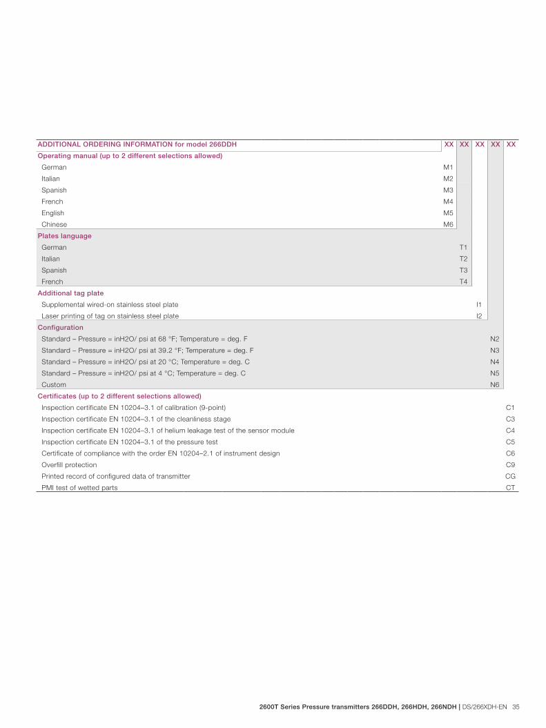
2600T Series Pressure transmitters 266DDH, 266HDH, 266NDH | DS/266XDH-EN 35
ADDITIONAL ORDERING INFORMATION for model 266DDH XX XX XX XX XX
Operating manual (up to 2 different selections allowed)
German M1
Italian M2
Spanish M3
French M4
English M5
Chinese M6
Plates language
German T1
Italian T2
Spanish T3
French T4
Additional tag plate
Supplemental wired-on stainless steel plate I1
Laser printing of tag on stainless steel plate I2
Configuration
Standard – Pressure = inH2O/ psi at 68 °F; Temperature = deg. F N2
Standard – Pressure = inH2O/ psi at 39.2 °F; Temperature = deg. F N3
Standard – Pressure = inH2O/ psi at 20 °C; Temperature = deg. C N4
Standard – Pressure = inH2O/ psi at 4 °C; Temperature = deg. C N5
Custom N6
Certificates (up to 2 different selections allowed)
Inspection certificate EN 10204–3.1 of calibration (9-point) C1
Inspection certificate EN 10204–3.1 of the cleanliness stage C3
Inspection certificate EN 10204–3.1 of helium leakage test of the sensor module C4
Inspection certificate EN 10204–3.1 of the pressure test C5
Certificate of compliance with the order EN 10204–2.1 of instrument design C6
Overfill protection C9
Printed record of configured data of transmitter CG
PMI test of wetted parts CT
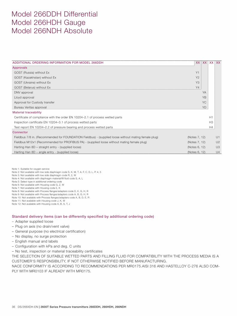
36 DS/266XDH-EN | 2600T Series Pressure transmitters 266DDH, 266HDH, 266NDH
Model 266DDH Differential Model 266HDH Gauge Model 266NDH Absolute
Note 1: Suitable for oxygen serviceNote 2: Not available with low side diaphragm code S, K, M, T, A, F, C, D, L, P, 4, 5Note 3: Not available with low side diaphragm code R, 2, WNote 4: Not available with diaphragm material/fill fluid code S, A, LNota 5: Select type in additional ordering codeNote 6: Not available with Housing code G, Z, WNote 7: Not available with Housing code E, KNote 8: Not available with Process flanges/adapters code D, E, G, H, RNote 9: Not available with Process flanges/adapters code A, B, G, H, RNote 10: Not available with Process flanges/adapters code A, B, D, E, RNote 11: Not available with Housing code J, K, WNote 12: Not available with Housing code A, B, S, T, J
Standard delivery items (can be differently specified by additional ordering code)– Adapter supplied loose– Plug on axis (no drain/vent valve)– General purpose (no electrical certification)– No display, no surge protection– English manual and labels– Configuration with kPa and deg. C units– No test, inspection or material traceability certificatesTHE SELECTION OF SUITABLE WETTED PARTS AND FILLING FLUID FOR COMPATIBILITY WITH THE PROCESS MEDIA IS A CUSTOMER'S RESPONSIBILITY, IF NOT OTHERWISE NOTIFIED BEFORE MANUFACTURING.NACE CONFORMITY IS ACCORDING TO RECOMMENDATIONS PER MR0175.AISI 316 AND HASTELLOY C-276 ALSO COM-PLY WITH MR0103 IF ALREADY WITH MR0175.
ADDITIONAL ORDERING INFORMATION FOR MODEL 266DDH XX XX XX XX
Approvals
GOST (Russia) without Ex Y1
GOST (Kazakhstan) without Ex Y2
GOST (Ukraine) without Ex Y3
GOST (Belarus) without Ex Y4
DNV approval YA
Lloyd approval YB
Approval for Custody transfer YC
Bureau Veritas approval YD
Material traceability
Certificate of compliance with the order EN 10204–2.1 of process wetted parts H1
Inspection certificate EN 10204–3.1 of process wetted parts H3
Test report EN 10204–2.2 of pressure bearing and process wetted parts H4
Connector
Fieldbus 7/8 in. (Recommended for FOUNDATION Fieldbus) - (supplied loose without mating female plug) (Notes 7, 12) U1
Fieldbus M12x1 (Recommended for PROFIBUS PA) - (supplied loose without mating female plug) (Notes 7, 12) U2
Harting Han 8D – straight entry - (supplied loose) (Notes 6, 12) U3
Harting Han 8D – angle entry - (supplied loose) (Notes 6, 12) U4

2600T Series Pressure transmitters 266DDH, 266HDH, 266NDH | DS/266XDH-EN 37
BASIC ORDERING INFORMATION model 266HDH Gauge Pressure Transmitter with direct mount sealSelect one character or set of characters from each category and specify complete catalog number.Refer to additional ordering information and specify one or more codes for each transmitter if additional options are required.BASE MODEL - 1st to 6th characters 2 6 6 H D H X X X X X
Gauge Pressure Transmitter with direct mount seal – BASE ACCURACY 0.06 %
SENSOR - Span limits - 7th characters
1.1 and 65 kPa 11 and 650 mbar 4.35 and 260 inH2O G
2.67 and 160 kPa 26.7 and 1600 mbar 10.7 and 642 inH2O H
10 and 600 kPa 0.1 and 6 bar 1.45 and 87 psi M
40 and 2400 kPa 0.4 and 24 bar 5.8 and 348 psi P
134 and 8000 kPa 1.34 and 80 bar 19.4 and 1160 psi Q
267 and 16000 kPa 2.67 and 160 bar 38.7 and 2320 psi S
Diaphragm material / Fill fluid - 8th characters
AISI 316 L ss Silicone oil R
AISI 316 L ss Inert fluid - Galden (Note 1) 2
AISI 316 L ss Inert fluid - Halocarbon (Note 1) W
Process connection (wetted parts) - 9th characters
Direct mount seal (one seal to be quoted separately) M
Housing material and electrical connection - 10th characters
Aluminium alloy ( barrel version) 1/2 – 14 NPT A
Aluminium alloy ( barrel version) M20 x 1.5 (CM 20) B
Aluminium alloy ( barrel version) Harting Han 8D connector (general purpose only) (Note 2) E
Aluminium alloy ( barrel version) Fieldbus connector (general purpose only) (Note 2) G
AISI 316 L ss ( barrel version) 1/2 – 14 NPT S
AISI 316 L ss ( barrel version) M20 x 1.5 (CM20) T
AISI 316 L ss ( barrel version) Fieldbus connector (general purpose only) (Note 2) Z
Aluminium alloy (DIN version) M20 x 1.5 (CM20) J
Aluminium alloy (DIN version) Harting Han 8D connector (general purpose only) (Note 2) K
Aluminium alloy (DIN version) Fieldbus connector (general purpose only) (Note 2) W
Output/Additional options - 11th characters
HART digital communication and 4 to 20 mA No additional options (Notes 3, 4) H
HART digital communication and 4 to 20 mA Options requested by “Additional ordering code” (Note 3) 1
PROFIBUS PA No additional options (Notes 3, 4) P
PROFIBUS PA Options requested by “Additional ordering code” (Note 4) 2
FOUNDATION Fieldbus No additional options (Notes 3, 4) F
FOUNDATION Fieldbus Options requested by “Additional ordering code” (Note 4) 3
HART and 4 to 20 mA Safety - certified to IEC 61508 No additional options (Notes 3, 4) T
HART and 4 to 20 mA Safety - certified to IEC 61508 Options requested by “Additional ordering code” (Note 3) 8
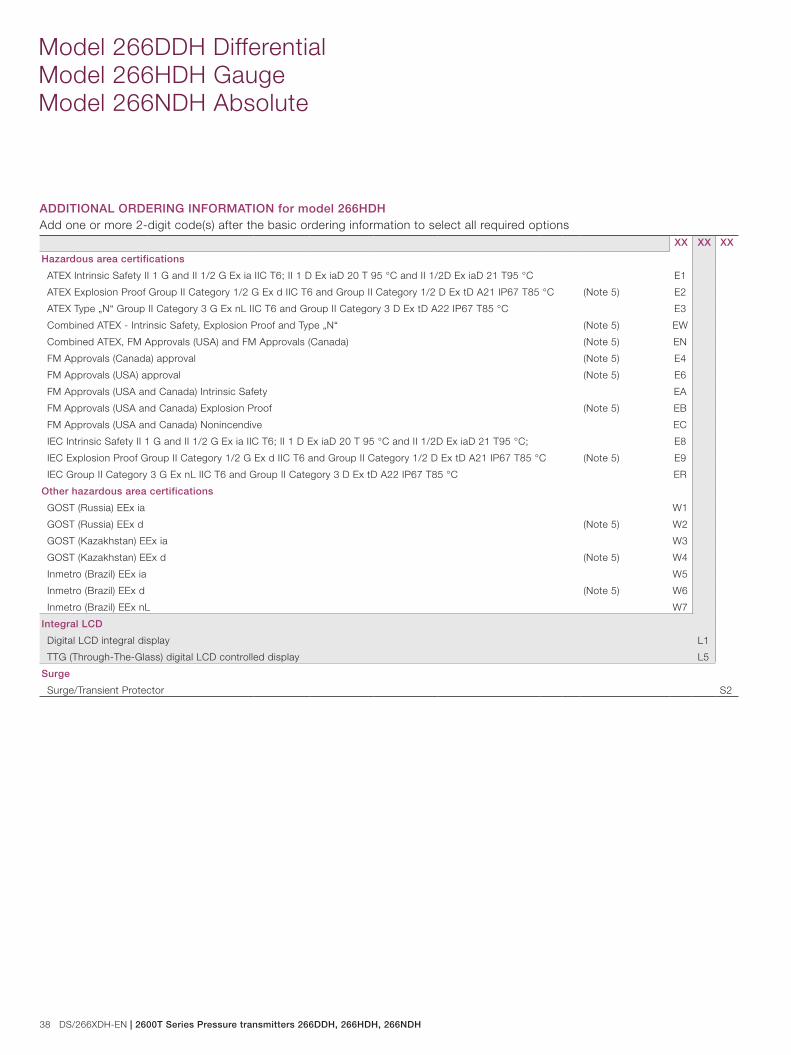
38 DS/266XDH-EN | 2600T Series Pressure transmitters 266DDH, 266HDH, 266NDH
Model 266DDH Differential Model 266HDH Gauge Model 266NDH Absolute
ADDITIONAL ORDERING INFORMATION for model 266HDHAdd one or more 2-digit code(s) after the basic ordering information to select all required options
XX XX XX
Hazardous area certifications
ATEX Intrinsic Safety II 1 G and II 1/2 G Ex ia IIC T6; II 1 D Ex iaD 20 T 95 °C and II 1/2D Ex iaD 21 T95 °C E1
ATEX Explosion Proof Group II Category 1/2 G Ex d IIC T6 and Group II Category 1/2 D Ex tD A21 IP67 T85 °C (Note 5) E2
ATEX Type „N“ Group II Category 3 G Ex nL IIC T6 and Group II Category 3 D Ex tD A22 IP67 T85 °C E3
Combined ATEX - Intrinsic Safety, Explosion Proof and Type „N“ (Note 5) EW
Combined ATEX, FM Approvals (USA) and FM Approvals (Canada) (Note 5) EN
FM Approvals (Canada) approval (Note 5) E4
FM Approvals (USA) approval (Note 5) E6
FM Approvals (USA and Canada) Intrinsic Safety EA
FM Approvals (USA and Canada) Explosion Proof (Note 5) EB
FM Approvals (USA and Canada) Nonincendive EC
IEC Intrinsic Safety II 1 G and II 1/2 G Ex ia IIC T6; II 1 D Ex iaD 20 T 95 °C and II 1/2D Ex iaD 21 T95 °C; E8
IEC Explosion Proof Group II Category 1/2 G Ex d IIC T6 and Group II Category 1/2 D Ex tD A21 IP67 T85 °C (Note 5) E9
IEC Group II Category 3 G Ex nL IIC T6 and Group II Category 3 D Ex tD A22 IP67 T85 °C ER
Other hazardous area certifications
GOST (Russia) EEx ia W1
GOST (Russia) EEx d (Note 5) W2
GOST (Kazakhstan) EEx ia W3
GOST (Kazakhstan) EEx d (Note 5) W4
Inmetro (Brazil) EEx ia W5
Inmetro (Brazil) EEx d (Note 5) W6
Inmetro (Brazil) EEx nL W7
Integral LCD
Digital LCD integral display L1
TTG (Through-The-Glass) digital LCD controlled display L5
Surge
Surge/Transient Protector S2
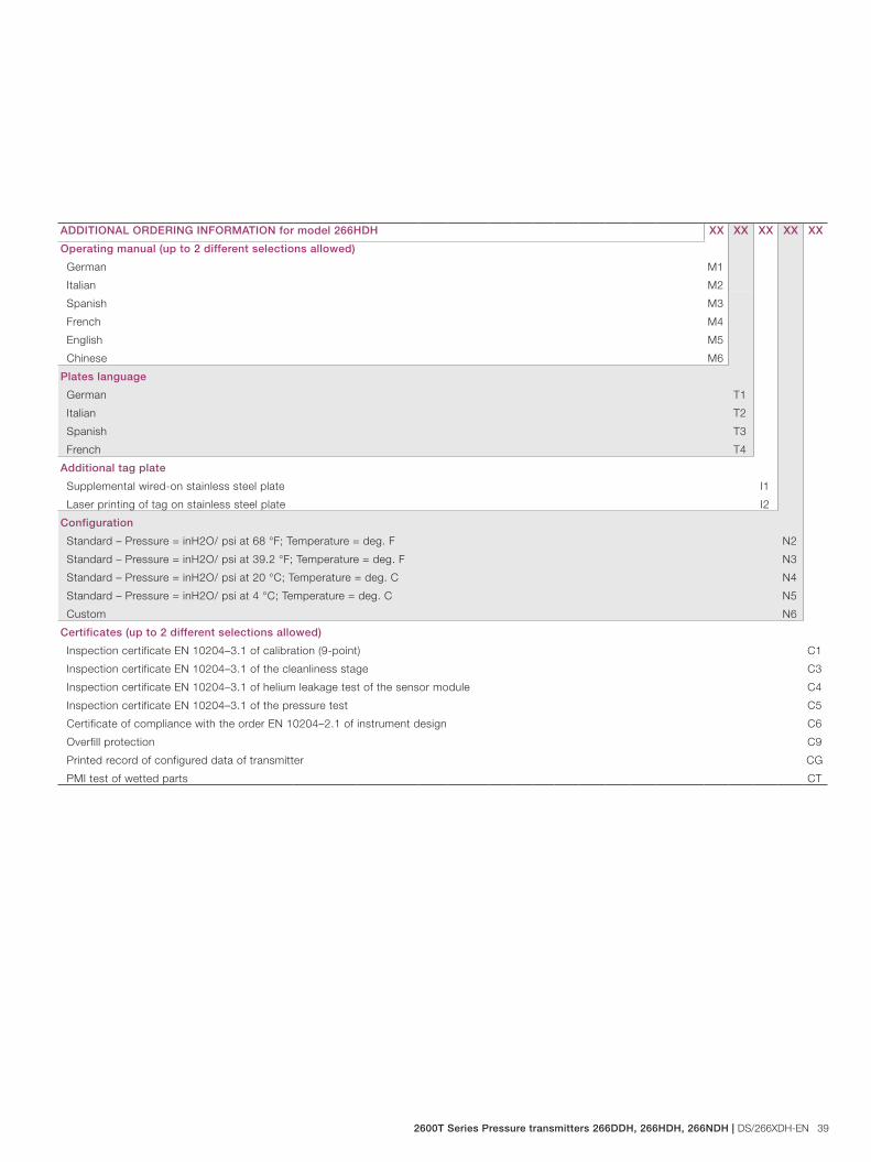
2600T Series Pressure transmitters 266DDH, 266HDH, 266NDH | DS/266XDH-EN 39
ADDITIONAL ORDERING INFORMATION for model 266HDH XX XX XX XX XX
Operating manual (up to 2 different selections allowed)
German M1
Italian M2
Spanish M3
French M4
English M5
Chinese M6
Plates language
German T1
Italian T2
Spanish T3
French T4
Additional tag plate
Supplemental wired-on stainless steel plate I1
Laser printing of tag on stainless steel plate I2
Configuration
Standard – Pressure = inH2O/ psi at 68 °F; Temperature = deg. F N2
Standard – Pressure = inH2O/ psi at 39.2 °F; Temperature = deg. F N3
Standard – Pressure = inH2O/ psi at 20 °C; Temperature = deg. C N4
Standard – Pressure = inH2O/ psi at 4 °C; Temperature = deg. C N5
Custom N6
Certificates (up to 2 different selections allowed)
Inspection certificate EN 10204–3.1 of calibration (9-point) C1
Inspection certificate EN 10204–3.1 of the cleanliness stage C3
Inspection certificate EN 10204–3.1 of helium leakage test of the sensor module C4
Inspection certificate EN 10204–3.1 of the pressure test C5
Certificate of compliance with the order EN 10204–2.1 of instrument design C6
Overfill protection C9
Printed record of configured data of transmitter CG
PMI test of wetted parts CT

40 DS/266XDH-EN | 2600T Series Pressure transmitters 266DDH, 266HDH, 266NDH
Model 266DDH Differential Model 266HDH Gauge Model 266NDH Absolute
ADDITIONAL ORDERING INFORMATION FOR MODEL 266HDH XX XX XX XX
Approvals
GOST (Russia) without Ex Y1
GOST (Kazakhstan) without Ex Y2
GOST (Ukraine) without Ex Y3
GOST (Belarus) without Ex Y4
DNV approval YA
Lloyd approval YB
Approval for Custody transfer YC
Bureau Veritas approval YD
Material traceability
Certificate of compliance with the order EN 10204–2.1 of process wetted parts H1
Inspection certificate EN 10204–3.1 of process wetted parts H3
Test report EN 10204–2.2 of pressure bearing and process wetted parts H4
Connector
Fieldbus 7/8 in. (Recommended for FOUNDATION Fieldbus) - (supplied loose without mating female plug) (Notes 4, 6) U1
Fieldbus M12x1 (Recommended for PROFIBUS PA) - (supplied loose without mating female plug) (Notes 4, 6) U2
Harting Han 8D – straight entry - (supplied loose) (Notes 3, 6) U3
Harting Han 8D – angle entry - (supplied loose) (Notes 3, 6) U4
Note 1: Suitable for oxygen serviceNota 2: Select type in additional ordering codeNote 3: Not available with Housing code G, Z, WNote 4: Not available with Housing code E, KNote 5: Not available with Housing code J, K, WNote 6: Not available with Housing code A, B, S, T, J
Standard delivery items (can be differently specified by additional ordering code)– General purpose (no electrical certification)– No display, no surge protection– English manual and labels– Configuration with kPa and deg. C units– No test, inspection or material traceability certificatesTHE SELECTION OF SUITABLE WETTED PARTS AND FILLING FLUID FOR COMPATIBILITY WITH THE PROCESS MEDIA IS A CUSTOMER'S RESPONSIBILITY, IF NOT OTHERWISE NOTIFIED BEFORE MANUFACTURING.NACE CONFORMITY IS ACCORDING TO RECOMMENDATIONS PER MR0175.AISI 316 AND HASTELLOY C-276 ALSO COM-PLY WITH MR0103 IF ALREADY WITH MR0175.
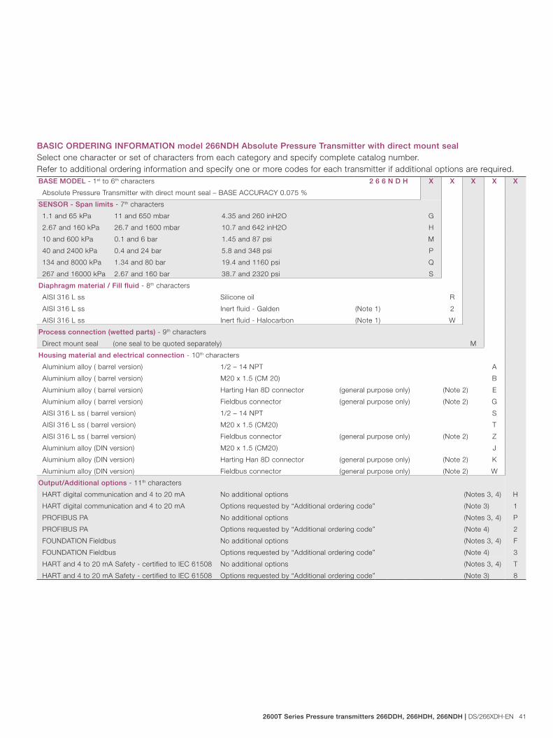
2600T Series Pressure transmitters 266DDH, 266HDH, 266NDH | DS/266XDH-EN 41
BASE MODEL - 1st to 6th characters 2 6 6 N D H X X X X X
Absolute Pressure Transmitter with direct mount seal – BASE ACCURACY 0.075 %
SENSOR - Span limits - 7th characters
1.1 and 65 kPa 11 and 650 mbar 4.35 and 260 inH2O G
2.67 and 160 kPa 26.7 and 1600 mbar 10.7 and 642 inH2O H
10 and 600 kPa 0.1 and 6 bar 1.45 and 87 psi M
40 and 2400 kPa 0.4 and 24 bar 5.8 and 348 psi P
134 and 8000 kPa 1.34 and 80 bar 19.4 and 1160 psi Q
267 and 16000 kPa 2.67 and 160 bar 38.7 and 2320 psi S
Diaphragm material / Fill fluid - 8th characters
AISI 316 L ss Silicone oil R
AISI 316 L ss Inert fluid - Galden (Note 1) 2
AISI 316 L ss Inert fluid - Halocarbon (Note 1) W
Process connection (wetted parts) - 9th characters
Direct mount seal (one seal to be quoted separately) M
Housing material and electrical connection - 10th characters
Aluminium alloy ( barrel version) 1/2 – 14 NPT A
Aluminium alloy ( barrel version) M20 x 1.5 (CM 20) B
Aluminium alloy ( barrel version) Harting Han 8D connector (general purpose only) (Note 2) E
Aluminium alloy ( barrel version) Fieldbus connector (general purpose only) (Note 2) G
AISI 316 L ss ( barrel version) 1/2 – 14 NPT S
AISI 316 L ss ( barrel version) M20 x 1.5 (CM20) T
AISI 316 L ss ( barrel version) Fieldbus connector (general purpose only) (Note 2) Z
Aluminium alloy (DIN version) M20 x 1.5 (CM20) J
Aluminium alloy (DIN version) Harting Han 8D connector (general purpose only) (Note 2) K
Aluminium alloy (DIN version) Fieldbus connector (general purpose only) (Note 2) W
Output/Additional options - 11th characters
HART digital communication and 4 to 20 mA No additional options (Notes 3, 4) H
HART digital communication and 4 to 20 mA Options requested by “Additional ordering code” (Note 3) 1
PROFIBUS PA No additional options (Notes 3, 4) P
PROFIBUS PA Options requested by “Additional ordering code” (Note 4) 2
FOUNDATION Fieldbus No additional options (Notes 3, 4) F
FOUNDATION Fieldbus Options requested by “Additional ordering code” (Note 4) 3
HART and 4 to 20 mA Safety - certified to IEC 61508 No additional options (Notes 3, 4) T
HART and 4 to 20 mA Safety - certified to IEC 61508 Options requested by “Additional ordering code” (Note 3) 8
BASIC ORDERING INFORMATION model 266NDH Absolute Pressure Transmitter with direct mount sealSelect one character or set of characters from each category and specify complete catalog number.Refer to additional ordering information and specify one or more codes for each transmitter if additional options are required.

42 DS/266XDH-EN | 2600T Series Pressure transmitters 266DDH, 266HDH, 266NDH
Model 266DDH Differential Model 266HDH Gauge Model 266NDH Absolute
ADDITIONAL ORDERING INFORMATION for model 266NDHAdd one or more 2-digit code(s) after the basic ordering information to select all required options
XX XX XX
Hazardous area certifications
ATEX Intrinsic Safety II 1 G and II 1/2 G Ex ia IIC T6; II 1 D Ex iaD 20 T 95 °C and II 1/2D Ex iaD 21 T95 °C E1
ATEX Explosion Proof Group II Category 1/2 G Ex d IIC T6 and Group II Category 1/2 D Ex tD A21 IP67 T85 °C (Note 5) E2
ATEX Type „N“ Group II Category 3 G Ex nL IIC T6 and Group II Category 3 D Ex tD A22 IP67 T85 °C E3
Combined ATEX - Intrinsic Safety, Explosion Proof and Type „N“ (Note 5) EW
Combined ATEX, FM Approvals (USA) and FM Approvals (Canada) (Note 5) EN
FM Approvals (Canada) approval (Note 5) E4
FM Approvals (USA) approval (Note 5) E6
FM Approvals (USA and Canada) Intrinsic Safety EA
FM Approvals (USA and Canada) Explosion Proof (Note 5) EB
FM Approvals (USA and Canada) Nonincendive EC
IEC Intrinsic Safety II 1 G and II 1/2 G Ex ia IIC T6; II 1 D Ex iaD 20 T 95 °C and II 1/2D Ex iaD 21 T95 °C; E8
IEC Explosion Proof Group II Category 1/2 G Ex d IIC T6 and Group II Category 1/2 D Ex tD A21 IP67 T85 °C (Note 5) E9
IEC Group II Category 3 G Ex nL IIC T6 and Group II Category 3 D Ex tD A22 IP67 T85 °C ER
Other hazardous area certifications
GOST (Russia) EEx ia W1
GOST (Russia) EEx d (Note 5) W2
GOST (Kazakhstan) EEx ia W3
GOST (Kazakhstan) EEx d (Note 5) W4
Inmetro (Brazil) EEx ia W5
Inmetro (Brazil) EEx d (Note 5) W6
Inmetro (Brazil) EEx nL W7
Integral LCD
Digital LCD integral display L1
TTG (Through-The-Glass) digital LCD controlled display L5
Surge
Surge/Transient Protector S2

2600T Series Pressure transmitters 266DDH, 266HDH, 266NDH | DS/266XDH-EN 43
ADDITIONAL ORDERING INFORMATION for model 266VSHAdd one or more 2-digit code(s) after the basic ordering information to select all required options ADDITIONAL ORDERING INFORMATION for model 266NDH XX XX XX XX XX
Operating manual (up to 2 different selections allowed)
German M1
Italian M2
Spanish M3
French M4
English M5
Chinese M6
Plates language
German T1
Italian T2
Spanish T3
French T4
Additional tag plate
Supplemental wired-on stainless steel plate I1
Laser printing of tag on stainless steel plate I2
Configuration
Standard – Pressure = inH2O/ psi at 68 °F; Temperature = deg. F N2
Standard – Pressure = inH2O/ psi at 39.2 °F; Temperature = deg. F N3
Standard – Pressure = inH2O/ psi at 20 °C; Temperature = deg. C N4
Standard – Pressure = inH2O/ psi at 4 °C; Temperature = deg. C N5
Custom N6
Certificates (up to 2 different selections allowed)
Inspection certificate EN 10204–3.1 of calibration (9-point) C1
Inspection certificate EN 10204–3.1 of the cleanliness stage C3
Inspection certificate EN 10204–3.1 of helium leakage test of the sensor module C4
Inspection certificate EN 10204–3.1 of the pressure test C5
Certificate of compliance with the order EN 10204–2.1 of instrument design C6
Overfill protection C9
Printed record of configured data of transmitter CG
PMI test of wetted parts CT
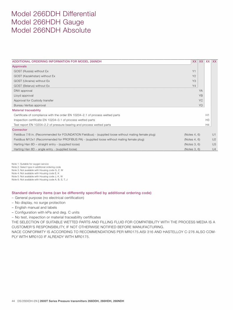
44 DS/266XDH-EN | 2600T Series Pressure transmitters 266DDH, 266HDH, 266NDH
Model 266DDH Differential Model 266HDH Gauge Model 266NDH Absolute
ADDITIONAL ORDERING INFORMATION FOR MODEL 266NDH XX XX XX XX
Approvals
GOST (Russia) without Ex Y1
GOST (Kazakhstan) without Ex Y2
GOST (Ukraine) without Ex Y3
GOST (Belarus) without Ex Y4
DNV approval YA
Lloyd approval YB
Approval for Custody transfer YC
Bureau Veritas approval YD
Material traceability
Certificate of compliance with the order EN 10204–2.1 of process wetted parts H1
Inspection certificate EN 10204–3.1 of process wetted parts H3
Test report EN 10204–2.2 of pressure bearing and process wetted parts H4
Connector
Fieldbus 7/8 in. (Recommended for FOUNDATION Fieldbus) - (supplied loose without mating female plug) (Notes 4, 6) U1
Fieldbus M12x1 (Recommended for PROFIBUS PA) - (supplied loose without mating female plug) (Notes 4, 6) U2
Harting Han 8D – straight entry - (supplied loose) (Notes 3, 6) U3
Harting Han 8D – angle entry - (supplied loose) (Notes 3, 6) U4
Note 1: Suitable for oxygen serviceNota 2: Select type in additional ordering codeNote 3: Not available with Housing code G, Z, WNote 4: Not available with Housing code E, KNote 5: Not available with Housing code J, K, WNote 6: Not available with Housing code A, B, S, T, J
Standard delivery items (can be differently specified by additional ordering code)– General purpose (no electrical certification)– No display, no surge protection– English manual and labels– Configuration with kPa and deg. C units– No test, inspection or material traceability certificatesTHE SELECTION OF SUITABLE WETTED PARTS AND FILLING FLUID FOR COMPATIBILITY WITH THE PROCESS MEDIA IS A CUSTOMER'S RESPONSIBILITY, IF NOT OTHERWISE NOTIFIED BEFORE MANUFACTURING.NACE CONFORMITY IS ACCORDING TO RECOMMENDATIONS PER MR0175.AISI 316 AND HASTELLOY C-276 ALSO COM-PLY WITH MR0103 IF ALREADY WITH MR0175.
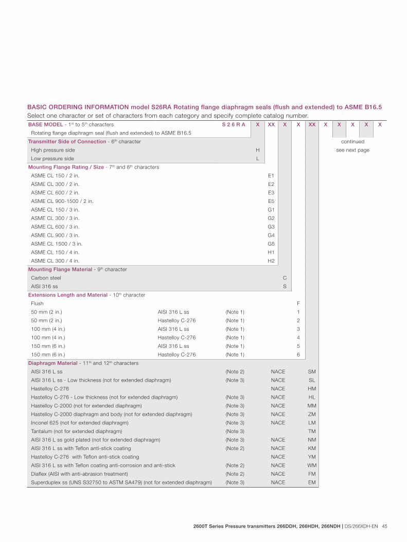
2600T Series Pressure transmitters 266DDH, 266HDH, 266NDH | DS/266XDH-EN 45
BASE MODEL - 1st to 5th characters S 2 6 R A X XX X X XX X X X X X
Rotating flange diaphragm seal (flush and extended) to ASME B16.5
Transmitter Side of Connection - 6th character continued
see next pageHigh pressure side H
Low pressure side L
Mounting Flange Rating / Size - 7th and 8th characters
ASME CL 150 / 2 in. E1
ASME CL 300 / 2 in. E2
ASME CL 600 / 2 in. E3
ASME CL 900-1500 / 2 in. E5
ASME CL 150 / 3 in. G1
ASME CL 300 / 3 in. G2
ASME CL 600 / 3 in. G3
ASME CL 900 / 3 in. G4
ASME CL 1500 / 3 in. G5
ASME CL 150 / 4 in. H1
ASME CL 300 / 4 in. H2
Mounting Flange Material - 9th character
Carbon steel C
AISI 316 ss S
Extensions Length and Material - 10th character
Flush F
50 mm (2 in.) AISI 316 L ss (Note 1) 1
50 mm (2 in.) Hastelloy C-276 (Note 1) 2
100 mm (4 in.) AISI 316 L ss (Note 1) 3
100 mm (4 in.) Hastelloy C-276 (Note 1) 4
150 mm (6 in.) AISI 316 L ss (Note 1) 5
150 mm (6 in.) Hastelloy C-276 (Note 1) 6
Diaphragm Material - 11th and 12th characters
AISI 316 L ss (Note 2) NACE SM
AISI 316 L ss - Low thickness (not for extended diaphragm) (Note 3) NACE SL
Hastelloy C-276 NACE HM
Hastelloy C-276 - Low thickness (not for extended diaphragm) (Note 3) NACE HL
Hastelloy C-2000 (not for extended diaphragm) (Note 3) NACE MM
Hastelloy C-2000 diaphragm and body (not for extended diaphragm) (Note 3) NACE ZM
Inconel 625 (not for extended diaphragm) (Note 3) NACE LM
Tantalum (not for extended diaphragm) (Note 3) TM
AISI 316 L ss gold plated (not for extended diaphragm) (Note 3) NACE NM
AISI 316 L ss with Teflon anti-stick coating (Note 2) NACE KM
Hastelloy C-276 with Teflon anti-stick coating NACE YM
AISI 316 L ss with Teflon coating anti-corrosion and anti-stick (Note 2) NACE WM
Diaflex (AISI with anti-abrasion treatment) (Note 2) NACE FM
Superduplex ss (UNS S32750 to ASTM SA479) (not for extended diaphragm) (Note 3) NACE EM
BASIC ORDERING INFORMATION model S26RA Rotating flange diaphragm seals (flush and extended) to ASME B16.5Select one character or set of characters from each category and specify complete catalog number.

46 DS/266XDH-EN | 2600T Series Pressure transmitters 266DDH, 266HDH, 266NDH
Model 266DDH Differential Model 266HDH Gauge Model 266NDH Absolute
BASIC ORDERING INFORMATION model S26RA S 2 6 R A X XX X X XX X X X X X X X
Seal Surface Finish - 13th character
Serrated (Note 4) 1 continued
Smooth (Note 15) 2 see next page
Capillary Protection - 14th character
AISI 316 L ss armour A
AISI 316 L ss armour with PVC protective cover B
Extension tube for direct mount seal (Note 5) N
Capillary Length m (Feet) - 15th character
Direct-mount construction (Note 6) 1
1 (3) (Note 7) A
1.5 (5) (Note 7) B
2 (7) (Note 7) C
2.5 (8) (Note 7) D
3 (10) (Note 7) E
3.5 (12) (Note 7) F
4 (13) (Note 7) G
4.5 (15) (Note 7) H
5 (17) (Note 7) J
5.5 (18) (Note 7) K
6 (20) (Note 7) L
6.5 (22) (Note 7) M
7 (23.5) (Note 7) N
7.5 (25) (Note 7) P
8 (27) (Note 7) Q
9 (30) (Note 7) R
10 (33) (Note 7) S
12 (40) (Note 7) T
14 (47) (Note 7) U
16 (53) (Note 7) V
Fill Fluid - 16th character
Silicone oil DC200 10 cSt S
Silicone oil Baysilone PD5 5 cSt P
Inert oil - Galden G5 (Note 8) N
Inert oil - Halocarbon 4.2 (Note 8) D
Silicone oil DC704 G
Silicone polymer Syltherm XLT C
Mineral oil Esso Marcol 122 (FDA approved) (Note 9) W
Vegetable oil Neobee M-20 (FDA approved) (Note 9) A
Glycerin-water 70% (FDA approved) (Note 9) B
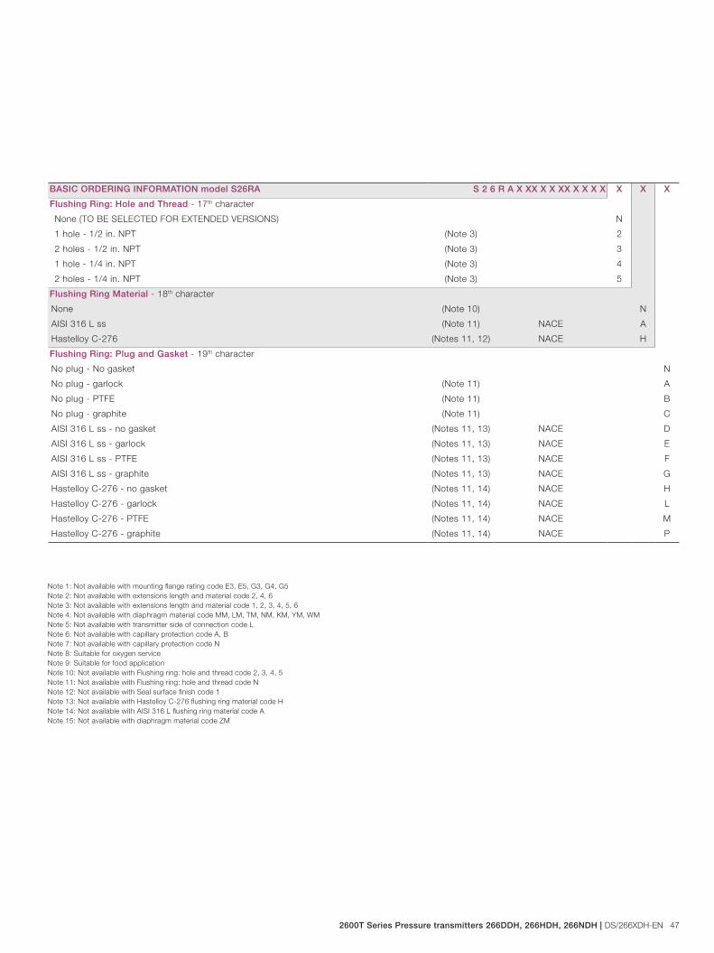
2600T Series Pressure transmitters 266DDH, 266HDH, 266NDH | DS/266XDH-EN 47
BASIC ORDERING INFORMATION model S26RA S 2 6 R A X XX X X XX X X X X X X X
Flushing Ring: Hole and Thread - 17th character
None (TO BE SELECTED FOR EXTENDED VERSIONS) N
1 hole - 1/2 in. NPT (Note 3) 2
2 holes - 1/2 in. NPT (Note 3) 3
1 hole - 1/4 in. NPT (Note 3) 4
2 holes - 1/4 in. NPT (Note 3) 5
Flushing Ring Material - 18th character
None (Note 10) N
AISI 316 L ss (Note 11) NACE A
Hastelloy C-276 (Notes 11, 12) NACE H
Flushing Ring: Plug and Gasket - 19th character
No plug - No gasket N
No plug - garlock (Note 11) A
No plug - PTFE (Note 11) B
No plug - graphite (Note 11) C
AISI 316 L ss - no gasket (Notes 11, 13) NACE D
AISI 316 L ss - garlock (Notes 11, 13) NACE E
AISI 316 L ss - PTFE (Notes 11, 13) NACE F
AISI 316 L ss - graphite (Notes 11, 13) NACE G
Hastelloy C-276 - no gasket (Notes 11, 14) NACE H
Hastelloy C-276 - garlock (Notes 11, 14) NACE L
Hastelloy C-276 - PTFE (Notes 11, 14) NACE M
Hastelloy C-276 - graphite (Notes 11, 14) NACE P
Note 1: Not available with mounting flange rating code E3, E5, G3, G4, G5Note 2: Not available with extensions length and material code 2, 4, 6Note 3: Not available with extensions length and material code 1, 2, 3, 4, 5, 6Note 4: Not available with diaphragm material code MM, LM, TM, NM, KM, YM, WMNote 5: Not available with transmitter side of connection code LNote 6: Not available with capillary protection code A, BNote 7: Not available with capillary protection code NNote 8: Suitable for oxygen serviceNote 9: Suitable for food applicationNote 10: Not available with Flushing ring: hole and thread code 2, 3, 4, 5Note 11: Not available with Flushing ring: hole and thread code NNote 12: Not available with Seal surface finish code 1Note 13: Not available with Hastelloy C-276 flushing ring material code HNote 14: Not available with AISI 316 L flushing ring material code ANote 15: Not available with diaphragm material code ZM
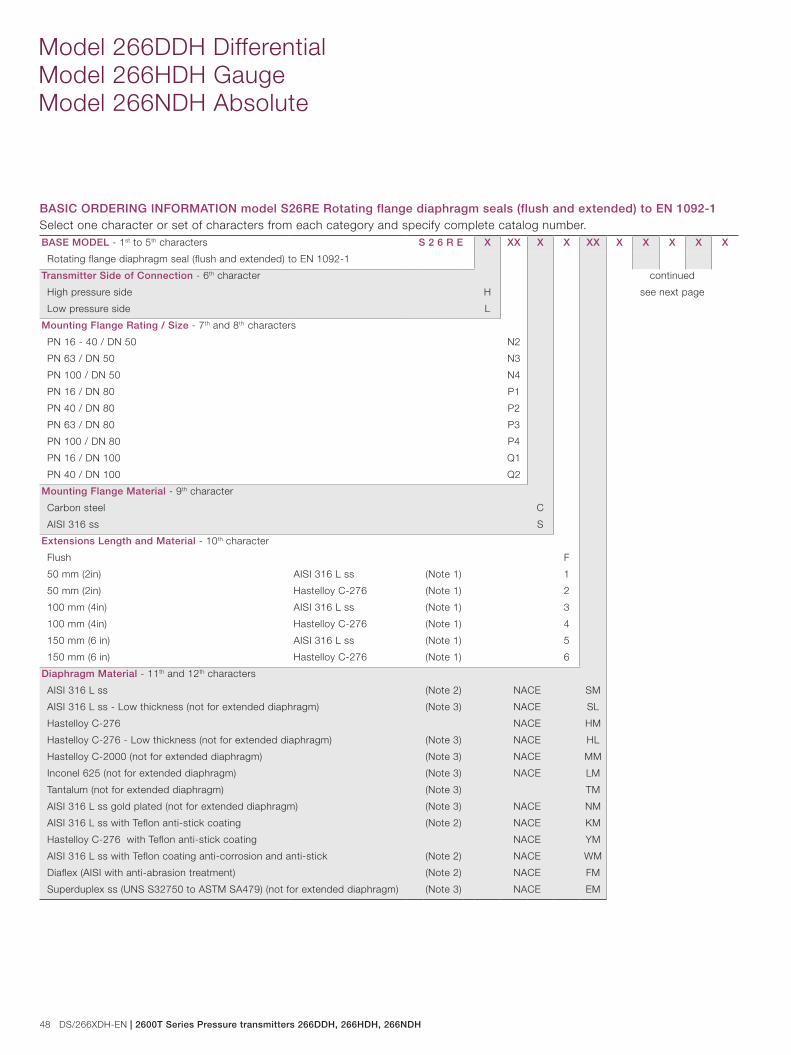
48 DS/266XDH-EN | 2600T Series Pressure transmitters 266DDH, 266HDH, 266NDH
Model 266DDH Differential Model 266HDH Gauge Model 266NDH Absolute
BASE MODEL - 1st to 5th characters S 2 6 R E X XX X X XX X X X X X
Rotating flange diaphragm seal (flush and extended) to EN 1092-1
Transmitter Side of Connection - 6th character continued
see next pageHigh pressure side H
Low pressure side L
Mounting Flange Rating / Size - 7th and 8th characters
PN 16 - 40 / DN 50 N2
PN 63 / DN 50 N3
PN 100 / DN 50 N4
PN 16 / DN 80 P1
PN 40 / DN 80 P2
PN 63 / DN 80 P3
PN 100 / DN 80 P4
PN 16 / DN 100 Q1
PN 40 / DN 100 Q2
Mounting Flange Material - 9th character
Carbon steel C
AISI 316 ss S
Extensions Length and Material - 10th character
Flush F
50 mm (2in) AISI 316 L ss (Note 1) 1
50 mm (2in) Hastelloy C-276 (Note 1) 2
100 mm (4in) AISI 316 L ss (Note 1) 3
100 mm (4in) Hastelloy C-276 (Note 1) 4
150 mm (6 in) AISI 316 L ss (Note 1) 5
150 mm (6 in) Hastelloy C-276 (Note 1) 6
Diaphragm Material - 11th and 12th characters
AISI 316 L ss (Note 2) NACE SM
AISI 316 L ss - Low thickness (not for extended diaphragm) (Note 3) NACE SL
Hastelloy C-276 NACE HM
Hastelloy C-276 - Low thickness (not for extended diaphragm) (Note 3) NACE HL
Hastelloy C-2000 (not for extended diaphragm) (Note 3) NACE MM
Inconel 625 (not for extended diaphragm) (Note 3) NACE LM
Tantalum (not for extended diaphragm) (Note 3) TM
AISI 316 L ss gold plated (not for extended diaphragm) (Note 3) NACE NM
AISI 316 L ss with Teflon anti-stick coating (Note 2) NACE KM
Hastelloy C-276 with Teflon anti-stick coating NACE YM
AISI 316 L ss with Teflon coating anti-corrosion and anti-stick (Note 2) NACE WM
Diaflex (AISI with anti-abrasion treatment) (Note 2) NACE FM
Superduplex ss (UNS S32750 to ASTM SA479) (not for extended diaphragm) (Note 3) NACE EM
BASIC ORDERING INFORMATION model S26RE Rotating flange diaphragm seals (flush and extended) to EN 1092-1Select one character or set of characters from each category and specify complete catalog number.
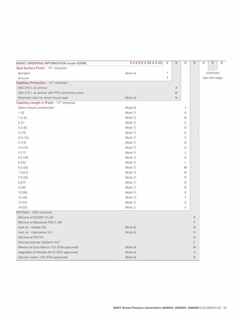
2600T Series Pressure transmitters 266DDH, 266HDH, 266NDH | DS/266XDH-EN 49
BASIC ORDERING INFORMATION model S26RE S 2 6 R E X XX X X XX X X X X X X X
Seal Surface Finish - 13th character
Serrated (Note 4) 1 continued
see next pageSmooth 2
Capillary Protection - 14th character
AISI 316 L ss armour A
AISI 316 L ss armour with PVC protective cover B
Extension tube for direct mount seal (Note 5) N
Capillary Length m (Feet) - 15th character
Direct-mount construction (Note 6) 1
1 (3) (Note 7) A
1.5 (5) (Note 7) B
2 (7) (Note 7) C
2.5 (8) (Note 7) D
3 (10) (Note 7) E
3.5 (12) (Note 7) F
4 (13) (Note 7) G
4.5 (15) (Note 7) H
5 (17) (Note 7) J
5.5 (18) (Note 7) K
6 (20) (Note 7) L
6.5 (22) (Note 7) M
7 (23.5) (Note 7) N
7.5 (25) (Note 7) P
8 (27) (Note 7) Q
9 (30) (Note 7) R
10 (33) (Note 7) S
12 (40) (Note 7) T
14 (47) (Note 7) U
16 (53) (Note 7) V
Fill Fluid - 16th character
Silicone oil DC200 10 cSt S
Silicone oil Baysilone PD5 5 cSt P
Inert oil - Galden G5 (Note 8) N
Inert oil - Halocarbon 4.2 (Note 8) D
Silicone oil DC704 G
Silicone polymer Syltherm XLT C
Mineral oil Esso Marcol 122 (FDA approved) (Note 9) W
Vegetable oil Neobee M-20 (FDA approved) (Note 9) A
Glycerin-water 70% (FDA approved) (Note 9) B
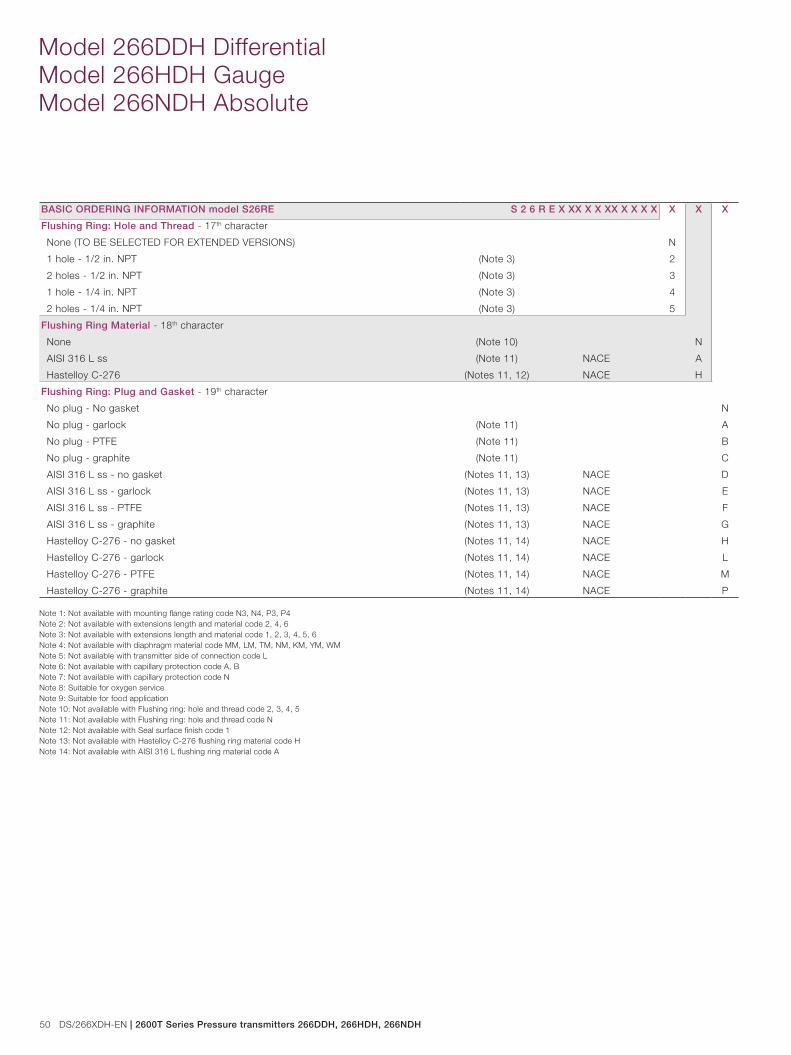
50 DS/266XDH-EN | 2600T Series Pressure transmitters 266DDH, 266HDH, 266NDH
Model 266DDH Differential Model 266HDH Gauge Model 266NDH Absolute
BASIC ORDERING INFORMATION model S26RE S 2 6 R E X XX X X XX X X X X X X X
Flushing Ring: Hole and Thread - 17th character
None (TO BE SELECTED FOR EXTENDED VERSIONS) N
1 hole - 1/2 in. NPT (Note 3) 2
2 holes - 1/2 in. NPT (Note 3) 3
1 hole - 1/4 in. NPT (Note 3) 4
2 holes - 1/4 in. NPT (Note 3) 5
Flushing Ring Material - 18th character
None (Note 10) N
AISI 316 L ss (Note 11) NACE A
Hastelloy C-276 (Notes 11, 12) NACE H
Flushing Ring: Plug and Gasket - 19th character
No plug - No gasket N
No plug - garlock (Note 11) A
No plug - PTFE (Note 11) B
No plug - graphite (Note 11) C
AISI 316 L ss - no gasket (Notes 11, 13) NACE D
AISI 316 L ss - garlock (Notes 11, 13) NACE E
AISI 316 L ss - PTFE (Notes 11, 13) NACE F
AISI 316 L ss - graphite (Notes 11, 13) NACE G
Hastelloy C-276 - no gasket (Notes 11, 14) NACE H
Hastelloy C-276 - garlock (Notes 11, 14) NACE L
Hastelloy C-276 - PTFE (Notes 11, 14) NACE M
Hastelloy C-276 - graphite (Notes 11, 14) NACE P
Note 1: Not available with mounting flange rating code N3, N4, P3, P4Note 2: Not available with extensions length and material code 2, 4, 6Note 3: Not available with extensions length and material code 1, 2, 3, 4, 5, 6Note 4: Not available with diaphragm material code MM, LM, TM, NM, KM, YM, WMNote 5: Not available with transmitter side of connection code LNote 6: Not available with capillary protection code A, BNote 7: Not available with capillary protection code NNote 8: Suitable for oxygen serviceNote 9: Suitable for food applicationNote 10: Not available with Flushing ring: hole and thread code 2, 3, 4, 5Note 11: Not available with Flushing ring: hole and thread code NNote 12: Not available with Seal surface finish code 1Note 13: Not available with Hastelloy C-276 flushing ring material code HNote 14: Not available with AISI 316 L flushing ring material code A
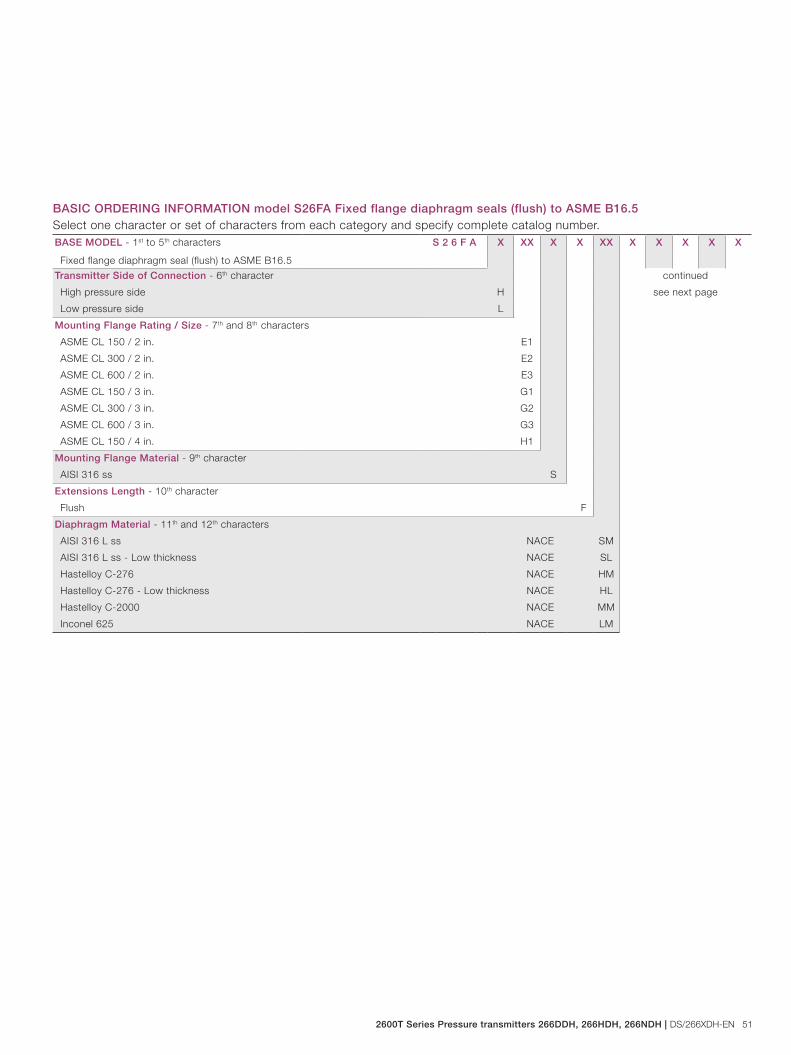
2600T Series Pressure transmitters 266DDH, 266HDH, 266NDH | DS/266XDH-EN 51
BASE MODEL - 1st to 5th characters S 2 6 F A X XX X X XX X X X X X
Fixed flange diaphragm seal (flush) to ASME B16.5
Transmitter Side of Connection - 6th character continued
see next pageHigh pressure side H
Low pressure side L
Mounting Flange Rating / Size - 7th and 8th characters
ASME CL 150 / 2 in. E1
ASME CL 300 / 2 in. E2
ASME CL 600 / 2 in. E3
ASME CL 150 / 3 in. G1
ASME CL 300 / 3 in. G2
ASME CL 600 / 3 in. G3
ASME CL 150 / 4 in. H1
Mounting Flange Material - 9th character
AISI 316 ss S
Extensions Length - 10th character
Flush F
Diaphragm Material - 11th and 12th characters
AISI 316 L ss NACE SM
AISI 316 L ss - Low thickness NACE SL
Hastelloy C-276 NACE HM
Hastelloy C-276 - Low thickness NACE HL
Hastelloy C-2000 NACE MM
Inconel 625 NACE LM
BASIC ORDERING INFORMATION model S26FA Fixed flange diaphragm seals (flush) to ASME B16.5Select one character or set of characters from each category and specify complete catalog number.
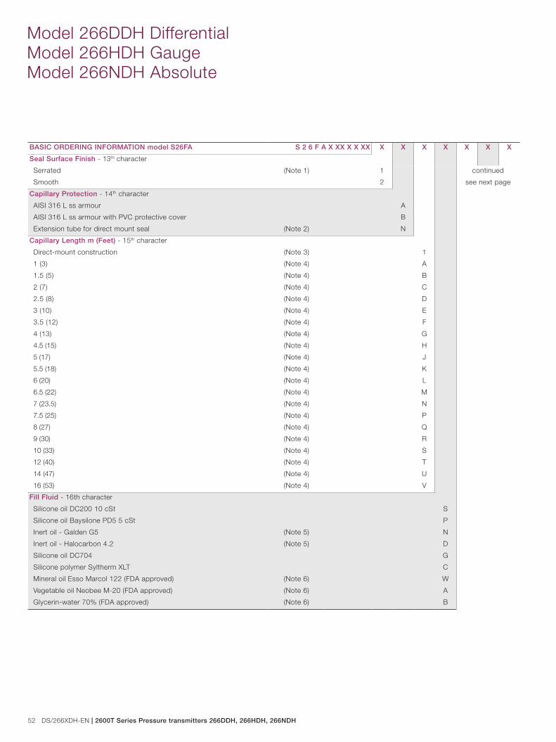
52 DS/266XDH-EN | 2600T Series Pressure transmitters 266DDH, 266HDH, 266NDH
Model 266DDH Differential Model 266HDH Gauge Model 266NDH Absolute
BASIC ORDERING INFORMATION model S26FA S 2 6 F A X XX X X XX X X X X X X X
Seal Surface Finish - 13th character
Serrated (Note 1) 1 continued
see next pageSmooth 2
Capillary Protection - 14th character
AISI 316 L ss armour A
AISI 316 L ss armour with PVC protective cover B
Extension tube for direct mount seal (Note 2) N
Capillary Length m (Feet) - 15th character
Direct-mount construction (Note 3) 1
1 (3) (Note 4) A
1.5 (5) (Note 4) B
2 (7) (Note 4) C
2.5 (8) (Note 4) D
3 (10) (Note 4) E
3.5 (12) (Note 4) F
4 (13) (Note 4) G
4.5 (15) (Note 4) H
5 (17) (Note 4) J
5.5 (18) (Note 4) K
6 (20) (Note 4) L
6.5 (22) (Note 4) M
7 (23.5) (Note 4) N
7.5 (25) (Note 4) P
8 (27) (Note 4) Q
9 (30) (Note 4) R
10 (33) (Note 4) S
12 (40) (Note 4) T
14 (47) (Note 4) U
16 (53) (Note 4) V
Fill Fluid - 16th character
Silicone oil DC200 10 cSt S
Silicone oil Baysilone PD5 5 cSt P
Inert oil - Galden G5 (Note 5) N
Inert oil - Halocarbon 4.2 (Note 5) D
Silicone oil DC704 G
Silicone polymer Syltherm XLT C
Mineral oil Esso Marcol 122 (FDA approved) (Note 6) W
Vegetable oil Neobee M-20 (FDA approved) (Note 6) A
Glycerin-water 70% (FDA approved) (Note 6) B
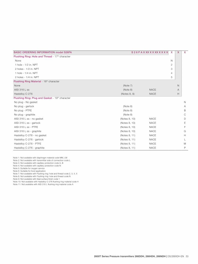
2600T Series Pressure transmitters 266DDH, 266HDH, 266NDH | DS/266XDH-EN 53
BASIC ORDERING INFORMATION model S26FA S 2 6 F A X XX X X XX X X X X X X X
Flushing Ring: Hole and Thread - 17th character
None N
1 hole - 1/2 in. NPT 2
2 holes - 1/2 in. NPT 3
1 hole - 1/4 in. NPT 4
2 holes - 1/4 in. NPT 5
Flushing Ring Material - 18th character
None (Note 7) N
AISI 316 L ss (Note 8) NACE A
Hastelloy C-276 (Notes 8, 9) NACE H
Flushing Ring: Plug and Gasket - 19th character
No plug - No gasket N
No plug - garlock (Note 8) A
No plug - PTFE (Note 8) B
No plug - graphite (Note 8) C
AISI 316 L ss - no gasket (Notes 8, 10) NACE D
AISI 316 L ss - garlock (Notes 8, 10) NACE E
AISI 316 L ss - PTFE (Notes 8, 10) NACE F
AISI 316 L ss - graphite (Notes 8, 10) NACE G
Hastelloy C-276 - no gasket (Notes 8, 11) NACE H
Hastelloy C-276 - garlock (Notes 8, 11) NACE L
Hastelloy C-276 - PTFE (Notes 8, 11) NACE M
Hastelloy C-276 - graphite (Notes 8, 11) NACE P
Note 1: Not available with diaphragm material code MM, LMNote 2: Not available with transmitter side of connection code LNote 3: Not available with capillary protection code A, BNote 4: Not available with capillary protection code NNote 5: Suitable for oxygen serviceNote 6: Suitable for food applicationNote 7: Not available with Flushing ring: hole and thread code 2, 3, 4, 5Note 8: Not available with Flushing ring: hole and thread code NNote 9: Not available with Seal surface finish code 1Note 10: Not available with Hastelloy C-276 flushing ring material code HNote 11: Not available with AISI 316 L flushing ring material code A
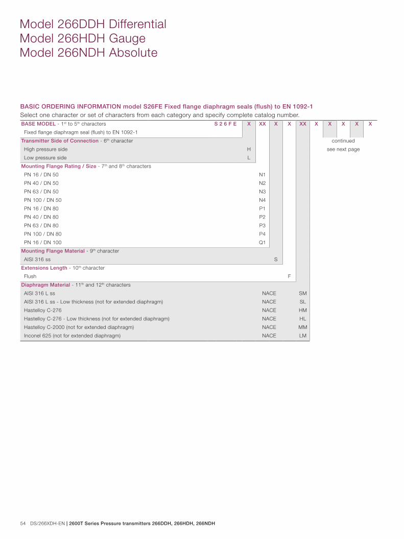
54 DS/266XDH-EN | 2600T Series Pressure transmitters 266DDH, 266HDH, 266NDH
Model 266DDH Differential Model 266HDH Gauge Model 266NDH Absolute
BASE MODEL - 1st to 5th characters S 2 6 F E X XX X X XX X X X X X
Fixed flange diaphragm seal (flush) to EN 1092-1
Transmitter Side of Connection - 6th character continued
see next pageHigh pressure side H
Low pressure side L
Mounting Flange Rating / Size - 7th and 8th characters
PN 16 / DN 50 N1
PN 40 / DN 50 N2
PN 63 / DN 50 N3
PN 100 / DN 50 N4
PN 16 / DN 80 P1
PN 40 / DN 80 P2
PN 63 / DN 80 P3
PN 100 / DN 80 P4
PN 16 / DN 100 Q1
Mounting Flange Material - 9th character
AISI 316 ss S
Extensions Length - 10th character
Flush F
Diaphragm Material - 11th and 12th characters
AISI 316 L ss NACE SM
AISI 316 L ss - Low thickness (not for extended diaphragm) NACE SL
Hastelloy C-276 NACE HM
Hastelloy C-276 - Low thickness (not for extended diaphragm) NACE HL
Hastelloy C-2000 (not for extended diaphragm) NACE MM
Inconel 625 (not for extended diaphragm) NACE LM
BASIC ORDERING INFORMATION model S26FE Fixed flange diaphragm seals (flush) to EN 1092-1Select one character or set of characters from each category and specify complete catalog number.
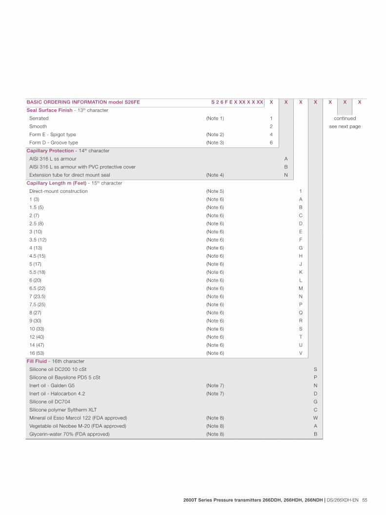
2600T Series Pressure transmitters 266DDH, 266HDH, 266NDH | DS/266XDH-EN 55
BASIC ORDERING INFORMATION model S26FE S 2 6 F E X XX X X XX X X X X X X X
Seal Surface Finish - 13th character
Serrated (Note 1) 1 continued
see next pageSmooth 2
Form E - Spigot type (Note 2) 4
Form D - Groove type (Note 3) 6
Capillary Protection - 14th character
AISI 316 L ss armour A
AISI 316 L ss armour with PVC protective cover B
Extension tube for direct mount seal (Note 4) N
Capillary Length m (Feet) - 15th character
Direct-mount construction (Note 5) 1
1 (3) (Note 6) A
1.5 (5) (Note 6) B
2 (7) (Note 6) C
2.5 (8) (Note 6) D
3 (10) (Note 6) E
3.5 (12) (Note 6) F
4 (13) (Note 6) G
4.5 (15) (Note 6) H
5 (17) (Note 6) J
5.5 (18) (Note 6) K
6 (20) (Note 6) L
6.5 (22) (Note 6) M
7 (23.5) (Note 6) N
7.5 (25) (Note 6) P
8 (27) (Note 6) Q
9 (30) (Note 6) R
10 (33) (Note 6) S
12 (40) (Note 6) T
14 (47) (Note 6) U
16 (53) (Note 6) V
Fill Fluid - 16th character
Silicone oil DC200 10 cSt S
Silicone oil Baysilone PD5 5 cSt P
Inert oil - Galden G5 (Note 7) N
Inert oil - Halocarbon 4.2 (Note 7) D
Silicone oil DC704 G
Silicone polymer Syltherm XLT C
Mineral oil Esso Marcol 122 (FDA approved) (Note 8) W
Vegetable oil Neobee M-20 (FDA approved) (Note 8) A
Glycerin-water 70% (FDA approved) (Note 8) B

56 DS/266XDH-EN | 2600T Series Pressure transmitters 266DDH, 266HDH, 266NDH
Model 266DDH Differential Model 266HDH Gauge Model 266NDH Absolute
BASIC ORDERING INFORMATION model S26FE S 2 6 F E X XX X X XX X X X X X X X
Flushing Ring: Hole and Thread - 17th character
None N
1 hole - 1/2 in. NPT (Note 9) 2
2 holes - 1/2 in. NPT (Note 9) 3
1 hole - 1/4 in. NPT (Note 9) 4
2 holes - 1/4 in. NPT (Note 9) 5
Flushing Ring Material - 18th character
None (Note 10) N
AISI 316 L ss (Note 11) NACE A
Hastelloy C-276 (Notes 11, 12) NACE H
Flushing Ring: Plug and Gasket - 19th character
No plug - No gasket N
No plug - garlock (Note 11) A
No plug - PTFE (Note 11) B
No plug - graphite (Note 11) C
AISI 316 L ss - no gasket (Notes 11, 13) NACE D
AISI 316 L ss - garlock (Notes 11, 13) NACE E
AISI 316 L ss - PTFE (Notes 11, 13) NACE F
AISI 316 L ss - graphite (Notes 11, 13) NACE G
Hastelloy C-276 - no gasket (Notes 11, 14) NACE H
Hastelloy C-276 - garlock (Notes 11, 14) NACE L
Hastelloy C-276 - PTFE (Notes 11, 14) NACE M
Hastelloy C-276 - graphite (Notes 11, 14) NACE P
Note 1: Not available with diaphragm material code MM, LMNote 2: Not available with DN 100 size code Q1combined with diaphragm material code SM, HM, HL, MM, LMNote 3: Not available with diaphragm material code HM, HL, MM, LMNote 4: Not available with transmitter side of connection code LNote 5: Not available with capillary protection code A, BNote 6: Not available with capillary protection code NNote 7: Suitable for oxygen serviceNote 8: Suitable for food applicationNote 9: Not available with Seal surface finish code 4, 6Note 10: Not available with Flushing ring: hole and thread code 2, 3, 4, 5Note 11: Not available with Flushing ring: hole and thread code NNote 12: Not available with Seal surface finish code 1Note 13: Not available with Hastelloy C-276 flushing ring material code HNote 14: Not available with AISI 316 L flushing ring material code A
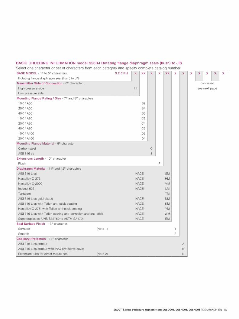
2600T Series Pressure transmitters 266DDH, 266HDH, 266NDH | DS/266XDH-EN 57
BASE MODEL - 1st to 5th characters S 2 6 R J X XX X X XX X X X X X X X
Rotating flange diaphragm seal (flush) to JIS
Transmitter Side of Connection - 6th character continued
see next pageHigh pressure side H
Low pressure side L
Mounting Flange Rating / Size - 7th and 8th characters
10K / A50 B2
20K / A50 B4
40K / A50 B6
10K / A80 C2
20K / A80 C4
40K / A80 C6
10K / A100 D2
20K / A100 D4
Mounting Flange Material - 9th character
Carbon steel C
AISI 316 ss S
Extensions Length - 10th character
Flush F
Diaphragm Material - 11th and 12th characters
AISI 316 L ss NACE SM
Hastelloy C-276 NACE HM
Hastelloy C-2000 NACE MM
Inconel 625 NACE LM
Tantalum TM
AISI 316 L ss gold plated NACE NM
AISI 316 L ss with Teflon anti-stick coating NACE KM
Hastelloy C-276 with Teflon anti-stick coating NACE YM
AISI 316 L ss with Teflon coating anti-corrosion and anti-stick NACE WM
Superduplex ss (UNS S32750 to ASTM SA479) NACE EM
Seal Surface Finish - 13th character
Serrated (Note 1) 1
Smooth 2
Capillary Protection - 14th character
AISI 316 L ss armour A
AISI 316 L ss armour with PVC protective cover B
Extension tube for direct mount seal (Note 2) N
BASIC ORDERING INFORMATION model S26RJ Rotating flange diaphragm seals (flush) to JISSelect one character or set of characters from each category and specify complete catalog number.
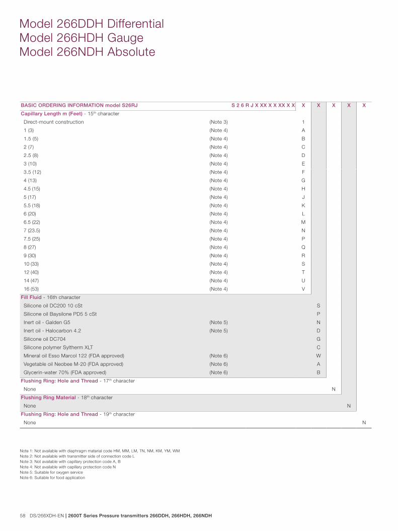
58 DS/266XDH-EN | 2600T Series Pressure transmitters 266DDH, 266HDH, 266NDH
Model 266DDH Differential Model 266HDH Gauge Model 266NDH Absolute
BASIC ORDERING INFORMATION model S26RJ S 2 6 R J X XX X X XX X X X X X X X
Capillary Length m (Feet) - 15th character
Direct-mount construction (Note 3) 1
1 (3) (Note 4) A
1.5 (5) (Note 4) B
2 (7) (Note 4) C
2.5 (8) (Note 4) D
3 (10) (Note 4) E
3.5 (12) (Note 4) F
4 (13) (Note 4) G
4.5 (15) (Note 4) H
5 (17) (Note 4) J
5.5 (18) (Note 4) K
6 (20) (Note 4) L
6.5 (22) (Note 4) M
7 (23.5) (Note 4) N
7.5 (25) (Note 4) P
8 (27) (Note 4) Q
9 (30) (Note 4) R
10 (33) (Note 4) S
12 (40) (Note 4) T
14 (47) (Note 4) U
16 (53) (Note 4) V
Fill Fluid - 16th character
Silicone oil DC200 10 cSt S
Silicone oil Baysilone PD5 5 cSt P
Inert oil - Galden G5 (Note 5) N
Inert oil - Halocarbon 4.2 (Note 5) D
Silicone oil DC704 G
Silicone polymer Syltherm XLT C
Mineral oil Esso Marcol 122 (FDA approved) (Note 6) W
Vegetable oil Neobee M-20 (FDA approved) (Note 6) A
Glycerin-water 70% (FDA approved) (Note 6) B
Flushing Ring: Hole and Thread - 17th character
None N
Flushing Ring Material - 18th character
None N
Flushing Ring: Hole and Thread - 19th character
None N
Note 1: Not available with diaphragm material code HM, MM, LM, TN, NM, KM, YM, WMNote 2: Not available with transmitter side of connection code LNote 3: Not available with capillary protection code A, BNote 4: Not available with capillary protection code NNote 5: Suitable for oxygen serviceNote 6: Suitable for food application
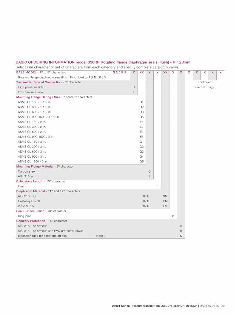
2600T Series Pressure transmitters 266DDH, 266HDH, 266NDH | DS/266XDH-EN 59
BASE MODEL - 1st to 5th characters S 2 6 R R X XX X X XX X X X X X X X
Rotating flange diaphragm seal (flush) Ring Joint to ASME B16.5
Transmitter Side of Connection - 6th character continued
see next pageHigh pressure side H
Low pressure side L
Mounting Flange Rating / Size - 7th and 8th characters
ASME CL 150 / 1 1/2 in. D1
ASME CL 300 / 1 1/2 in. D2
ASME CL 600 / 1 1/2 in. D3
ASME CL 900-1500 / 1 1/2 in. D5
ASME CL 150 / 2 in. E1
ASME CL 300 / 2 in. E2
ASME CL 600 / 2 in. E3
ASME CL 900-1500 / 2 in. E5
ASME CL 150 / 3 in. G1
ASME CL 300 / 3 in. G2
ASME CL 600 / 3 in. G3
ASME CL 900 / 3 in. G4
ASME CL 1500 / 3 in. G5
Mounting Flange Material - 9th character
Carbon steel C
AISI 316 ss S
Extensions Length - 10th character
Flush F
Diaphragm Material - 11th and 12th characters
AISI 316 L ss NACE SM
Hastelloy C-276 NACE HM
Inconel 625 NACE LM
Seal Surface Finish - 13th character
Ring joint 3
Capillary Protection - 14th character
AISI 316 L ss armour A
AISI 316 L ss armour with PVC protective cover B
Extension tube for direct mount seal (Note 1) N
BASIC ORDERING INFORMATION model S26RR Rotating flange diaphragm seals (flush) - Ring JointSelect one character or set of characters from each category and specify complete catalog number.
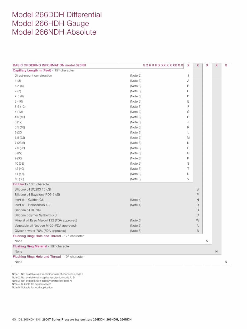
60 DS/266XDH-EN | 2600T Series Pressure transmitters 266DDH, 266HDH, 266NDH
Model 266DDH Differential Model 266HDH Gauge Model 266NDH Absolute
BASIC ORDERING INFORMATION model S26RR S 2 6 R R X XX X X XX X X X X X X X
Capillary Length m (Feet) - 15th character
Direct-mount construction (Note 2) 1
1 (3) (Note 3) A
1.5 (5) (Note 3) B
2 (7) (Note 3) C
2.5 (8) (Note 3) D
3 (10) (Note 3) E
3.5 (12) (Note 3) F
4 (13) (Note 3) G
4.5 (15) (Note 3) H
5 (17) (Note 3) J
5.5 (18) (Note 3) K
6 (20) (Note 3) L
6.5 (22) (Note 3) M
7 (23.5) (Note 3) N
7.5 (25) (Note 3) P
8 (27) (Note 3) Q
9 (30) (Note 3) R
10 (33) (Note 3) S
12 (40) (Note 3) T
14 (47) (Note 3) U
16 (53) (Note 3) V
Fill Fluid - 16th character
Silicone oil DC200 10 cSt S
Silicone oil Baysilone PD5 5 cSt P
Inert oil - Galden G5 (Note 4) N
Inert oil - Halocarbon 4.2 (Note 4) D
Silicone oil DC704 G
Silicone polymer Syltherm XLT C
Mineral oil Esso Marcol 122 (FDA approved) (Note 5) W
Vegetable oil Neobee M-20 (FDA approved) (Note 5) A
Glycerin-water 70% (FDA approved) (Note 5) B
Flushing Ring: Hole and Thread - 17th character
None N
Flushing Ring Material - 18th character
None N
Flushing Ring: Hole and Thread - 19th character
None N
Note 1: Not available with transmitter side of connection code LNote 2: Not available with capillary protection code A, BNote 3: Not available with capillary protection code NNote 4: Suitable for oxygen serviceNote 5: Suitable for food application

2600T Series Pressure transmitters 266DDH, 266HDH, 266NDH | DS/266XDH-EN 61
BASE MODEL - 1st to 5th characters S 2 6 M A X XX X XX X X X X X
Off-line flange diaphragm seal to ASME B16.5
Transmitter Side of Connection - 6th character continued
see next pageHigh pressure side H
Low pressure side L
Mounting Flange Rating / Size - 7th and 8th characters
ASME CL 150 / 1/2 in. A1
ASME CL 300 / 1/2 in. A2
ASME CL 150 / 1 in. C1
ASME CL 300 / 1 in. C2
ASME CL 150 / 1 1/2 in. D1
ASME CL 300 / 1 1/2 in. D2
Mounting Flange Material / Seat Form - 9th character
AISI 316 ss / Form RF (raised face) - serrated finish NACE (Note 6) S
Hastelloy C-276 / Form RF (raised face) - serrated finish NACE (Note 6) H
Hastelloy C-2000 / Form RF (raised face) - serrated finish NACE (Note 7) Y
Diaphragm Material - 10th and 11th characters
AISI 316 L ss NACE SM
Hastelloy C-276 NACE HM
Hastelloy C-2000 NACE MM
Hastelloy C-2000 diaphragm and body NACE ZM
Inconel 625 NACE LM
Tantalum TM
AISI 316 L ss gold plated NACE NM
Capillary Protection - 12th character
AISI 316 L ss armour A
AISI 316 L ss armour with PVC protective cover B
Extension tube for direct mount seal (Note 1) N
BASIC ORDERING INFORMATION model S26MA Off-line flange diaphragm sealsSelect one character or set of characters from each category and specify complete catalog number.
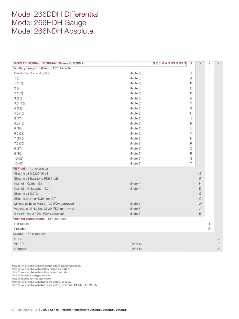
62 DS/266XDH-EN | 2600T Series Pressure transmitters 266DDH, 266HDH, 266NDH
Model 266DDH Differential Model 266HDH Gauge Model 266NDH Absolute
BASIC ORDERING INFORMATION model S26MA S 2 6 M A X XX X XX X X X X X
Capillary Length m (Feet) - 13th character
Direct-mount construction (Note 2) 1
1 (3) (Note 3) A
1.5 (5) (Note 3) B
2 (7) (Note 3) C
2.5 (8) (Note 3) D
3 (10) (Note 3) E
3.5 (12) (Note 3) F
4 (13) (Note 3) G
4.5 (15) (Note 3) H
5 (17) (Note 3) J
5.5 (18) (Note 3) K
6 (20) (Note 3) L
6.5 (22) (Note 3) M
7 (23.5) (Note 3) N
7.5 (25) (Note 3) P
8 (27) (Note 3) Q
9 (30) (Note 3) R
10 (33) (Note 3) S
12 (40) (Note 3) T
Fill Fluid - 14th character
Silicone oil DC200 10 cSt S
Silicone oil Baysilone PD5 5 cSt P
Inert oil - Galden G5 (Note 4) N
Inert oil - Halocarbon 4.2 (Note 4) D
Silicone oil DC704 G
Silicone polymer Syltherm XLT C
Mineral oil Esso Marcol 122 (FDA approved) (Note 5) W
Vegetable oil Neobee M-20 (FDA approved) (Note 5) A
Glycerin-water 70% (FDA approved) (Note 5) B
Flushing Connections - 15th character
Not required 1
Provided Q
Gasket - 16th character
PTFE 2
Viton™ (Note 6) 3
Graphite (Note 6) 7
Note 1: Not available with transmitter side of connection code LNote 2: Not available with capillary protection code A, BNote 3: Not available with capillary protection code NNote 4: Suitable for oxygen serviceNote 5: Suitable for food applicationNote 6: Not available with diaphragm material code ZMNote 7: Not available with diaphragm material code SM, HM, MM, LM, TM, NM
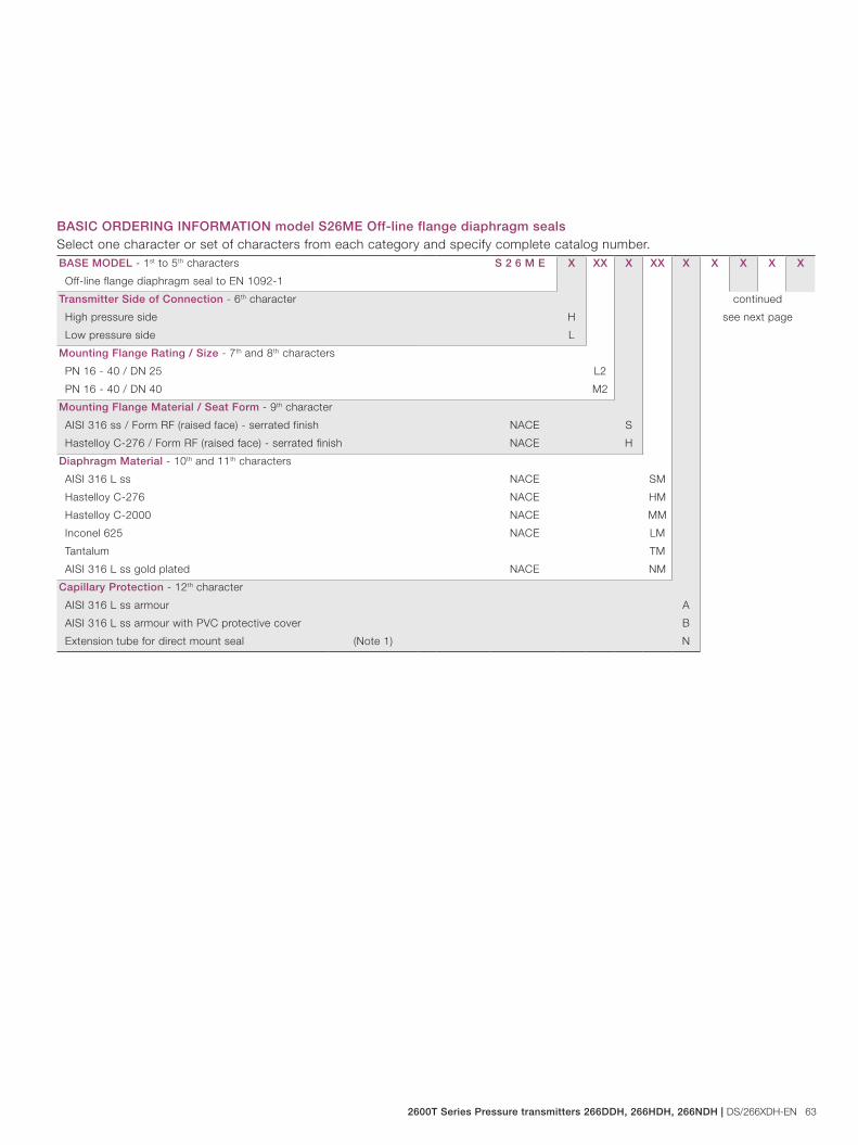
2600T Series Pressure transmitters 266DDH, 266HDH, 266NDH | DS/266XDH-EN 63
BASE MODEL - 1st to 5th characters S 2 6 M E X XX X XX X X X X X
Off-line flange diaphragm seal to EN 1092-1
Transmitter Side of Connection - 6th character continued
see next pageHigh pressure side H
Low pressure side L
Mounting Flange Rating / Size - 7th and 8th characters
PN 16 - 40 / DN 25 L2
PN 16 - 40 / DN 40 M2
Mounting Flange Material / Seat Form - 9th character
AISI 316 ss / Form RF (raised face) - serrated finish NACE S
Hastelloy C-276 / Form RF (raised face) - serrated finish NACE H
Diaphragm Material - 10th and 11th characters
AISI 316 L ss NACE SM
Hastelloy C-276 NACE HM
Hastelloy C-2000 NACE MM
Inconel 625 NACE LM
Tantalum TM
AISI 316 L ss gold plated NACE NM
Capillary Protection - 12th character
AISI 316 L ss armour A
AISI 316 L ss armour with PVC protective cover B
Extension tube for direct mount seal (Note 1) N
BASIC ORDERING INFORMATION model S26ME Off-line flange diaphragm sealsSelect one character or set of characters from each category and specify complete catalog number.
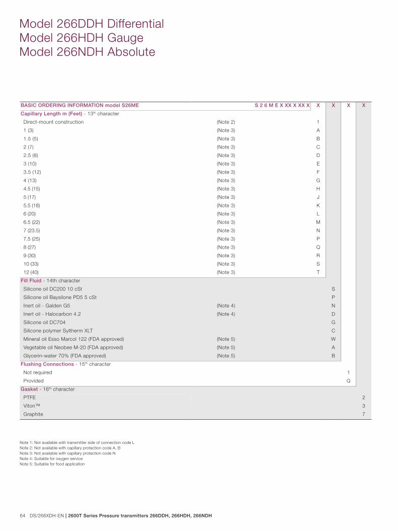
64 DS/266XDH-EN | 2600T Series Pressure transmitters 266DDH, 266HDH, 266NDH
Model 266DDH Differential Model 266HDH Gauge Model 266NDH Absolute
BASIC ORDERING INFORMATION model S26ME S 2 6 M E X XX X XX X X X X X
Capillary Length m (Feet) - 13th character
Direct-mount construction (Note 2) 1
1 (3) (Note 3) A
1.5 (5) (Note 3) B
2 (7) (Note 3) C
2.5 (8) (Note 3) D
3 (10) (Note 3) E
3.5 (12) (Note 3) F
4 (13) (Note 3) G
4.5 (15) (Note 3) H
5 (17) (Note 3) J
5.5 (18) (Note 3) K
6 (20) (Note 3) L
6.5 (22) (Note 3) M
7 (23.5) (Note 3) N
7.5 (25) (Note 3) P
8 (27) (Note 3) Q
9 (30) (Note 3) R
10 (33) (Note 3) S
12 (40) (Note 3) T
Fill Fluid - 14th character
Silicone oil DC200 10 cSt S
Silicone oil Baysilone PD5 5 cSt P
Inert oil - Galden G5 (Note 4) N
Inert oil - Halocarbon 4.2 (Note 4) D
Silicone oil DC704 G
Silicone polymer Syltherm XLT C
Mineral oil Esso Marcol 122 (FDA approved) (Note 5) W
Vegetable oil Neobee M-20 (FDA approved) (Note 5) A
Glycerin-water 70% (FDA approved) (Note 5) B
Flushing Connections - 15th character
Not required 1
Provided Q
Gasket - 16th character
PTFE 2
Viton™ 3
Graphite 7
Note 1: Not available with transmitter side of connection code LNote 2: Not available with capillary protection code A, BNote 3: Not available with capillary protection code NNote 4: Suitable for oxygen serviceNote 5: Suitable for food application
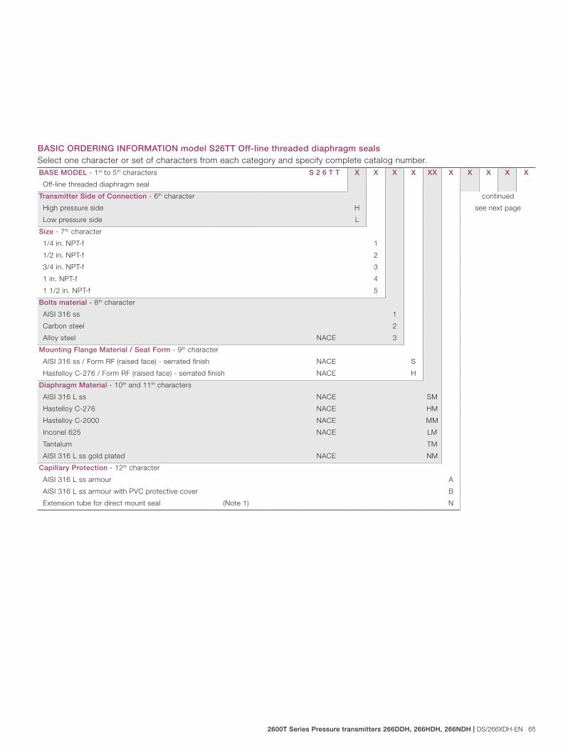
2600T Series Pressure transmitters 266DDH, 266HDH, 266NDH | DS/266XDH-EN 65
BASE MODEL - 1st to 5th characters S 2 6 T T X X X X XX X X X X X
Off-line threaded diaphragm seal
Transmitter Side of Connection - 6th character continued
see next pageHigh pressure side H
Low pressure side L
Size - 7th character
1/4 in. NPT-f 1
1/2 in. NPT-f 2
3/4 in. NPT-f 3
1 in. NPT-f 4
1 1/2 in. NPT-f 5
Bolts material - 8th character
AISI 316 ss 1
Carbon steel 2
Alloy steel NACE 3
Mounting Flange Material / Seat Form - 9th character
AISI 316 ss / Form RF (raised face) - serrated finish NACE S
Hastelloy C-276 / Form RF (raised face) - serrated finish NACE H
Diaphragm Material - 10th and 11th characters
AISI 316 L ss NACE SM
Hastelloy C-276 NACE HM
Hastelloy C-2000 NACE MM
Inconel 625 NACE LM
Tantalum TM
AISI 316 L ss gold plated NACE NM
Capillary Protection - 12th character
AISI 316 L ss armour A
AISI 316 L ss armour with PVC protective cover B
Extension tube for direct mount seal (Note 1) N
BASIC ORDERING INFORMATION model S26TT Off-line threaded diaphragm sealsSelect one character or set of characters from each category and specify complete catalog number.
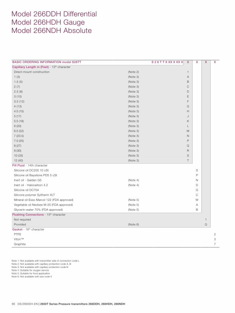
66 DS/266XDH-EN | 2600T Series Pressure transmitters 266DDH, 266HDH, 266NDH
Model 266DDH Differential Model 266HDH Gauge Model 266NDH Absolute
BASIC ORDERING INFORMATION model S26TT S 2 6 T T X XX X XX X X X X X
Capillary Length m (Feet) - 13th character
Direct-mount construction (Note 2) 1
1 (3) (Note 3) A
1.5 (5) (Note 3) B
2 (7) (Note 3) C
2.5 (8) (Note 3) D
3 (10) (Note 3) E
3.5 (12) (Note 3) F
4 (13) (Note 3) G
4.5 (15) (Note 3) H
5 (17) (Note 3) J
5.5 (18) (Note 3) K
6 (20) (Note 3) L
6.5 (22) (Note 3) M
7 (23.5) (Note 3) N
7.5 (25) (Note 3) P
8 (27) (Note 3) Q
9 (30) (Note 3) R
10 (33) (Note 3) S
12 (40) (Note 3) T
Fill Fluid - 14th character
Silicone oil DC200 10 cSt S
Silicone oil Baysilone PD5 5 cSt P
Inert oil - Galden G5 (Note 4) N
Inert oil - Halocarbon 4.2 (Note 4) D
Silicone oil DC704 G
Silicone polymer Syltherm XLT C
Mineral oil Esso Marcol 122 (FDA approved) (Note 5) W
Vegetable oil Neobee M-20 (FDA approved) (Note 5) A
Glycerin-water 70% (FDA approved) (Note 5) B
Flushing Connections - 15th character
Not required 1
Provided (Note 6) Q
Gasket - 16th character
PTFE 2
Viton™ 3
Graphite 7
Note 1: Not available with transmitter side of connection code LNote 2: Not available with capillary protection code A, BNote 3: Not available with capillary protection code NNote 4: Suitable for oxygen serviceNote 5: Suitable for food applicationNote 6: Not available with size code 5
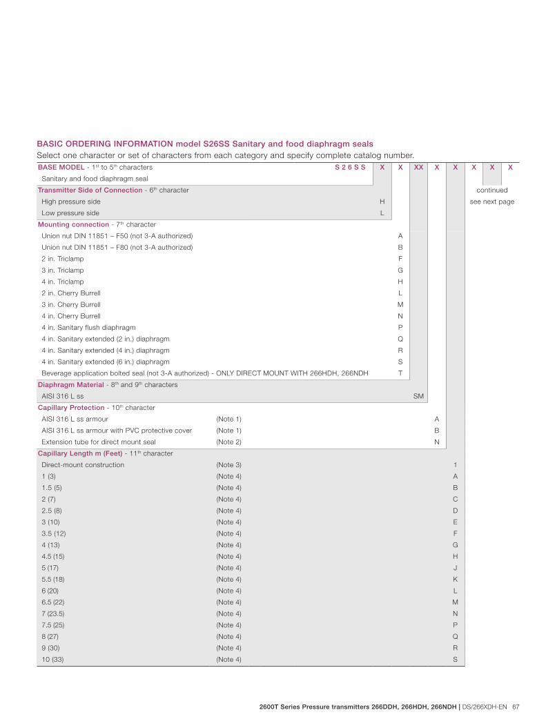
2600T Series Pressure transmitters 266DDH, 266HDH, 266NDH | DS/266XDH-EN 67
BASIC ORDERING INFORMATION model S26SS Sanitary and food diaphragm sealsSelect one character or set of characters from each category and specify complete catalog number.BASE MODEL - 1st to 5th characters S 2 6 S S X X XX X X X X X
Sanitary and food diaphragm seal
Transmitter Side of Connection - 6th character continued
see next pageHigh pressure side H
Low pressure side L
Mounting connection - 7th character
Union nut DIN 11851 – F50 (not 3-A authorized) A
Union nut DIN 11851 – F80 (not 3-A authorized) B
2 in. Triclamp F
3 in. Triclamp G
4 in. Triclamp H
2 in. Cherry Burrell L
3 in. Cherry Burrell M
4 in. Cherry Burrell N
4 in. Sanitary flush diaphragm P
4 in. Sanitary extended (2 in.) diaphragm Q
4 in. Sanitary extended (4 in.) diaphragm R
4 in. Sanitary extended (6 in.) diaphragm S
Beverage application bolted seal (not 3-A authorized) - ONLY DIRECT MOUNT WITH 266HDH, 266NDH T
Diaphragm Material - 8th and 9th characters
AISI 316 L ss SM
Capillary Protection - 10th character
AISI 316 L ss armour (Note 1) A
AISI 316 L ss armour with PVC protective cover (Note 1) B
Extension tube for direct mount seal (Note 2) N
Capillary Length m (Feet) - 11th character
Direct-mount construction (Note 3) 1
1 (3) (Note 4) A
1.5 (5) (Note 4) B
2 (7) (Note 4) C
2.5 (8) (Note 4) D
3 (10) (Note 4) E
3.5 (12) (Note 4) F
4 (13) (Note 4) G
4.5 (15) (Note 4) H
5 (17) (Note 4) J
5.5 (18) (Note 4) K
6 (20) (Note 4) L
6.5 (22) (Note 4) M
7 (23.5) (Note 4) N
7.5 (25) (Note 4) P
8 (27) (Note 4) Q
9 (30) (Note 4) R
10 (33) (Note 4) S
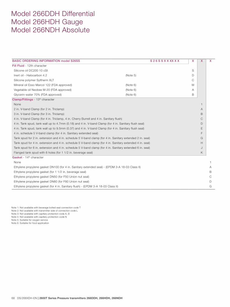
68 DS/266XDH-EN | 2600T Series Pressure transmitters 266DDH, 266HDH, 266NDH
Model 266DDH Differential Model 266HDH Gauge Model 266NDH Absolute
BASIC ORDERING INFORMATION model S26SS S 2 6 S S X X XX X X X X X
Fill Fluid - 12th character
Silicone oil DC200 10 cSt S
Inert oil - Halocarbon 4.2 (Note 5) D
Silicone polymer Syltherm XLT C
Mineral oil Esso Marcol 122 (FDA approved) (Note 6) W
Vegetable oil Neobee M-20 (FDA approved) (Note 6) A
Glycerin-water 70% (FDA approved) (Note 6) B
Clamp/Fittings - 13th character
None 1
2 in. V-band Clamp (for 2 in. Triclamp) A
3 in. V-band Clamp (for 3 in. Triclamp) B
4 in. V-band Clamp (for 4 in. Triclamp, 4 in. Cherry Burrell and 4 in. Sanitary flush) C
4 in. Tank spud, tank wall up to 4.7mm (0.18) and 4 in. V-band Clamp (for 4 in. Sanitary flush seal) D
4 in. Tank spud, tank wall up to 9.5mm (0.37) and 4 in. V-band Clamp (for 4 in. Sanitary flush seal) E
4 in. schedule 5 V-band clamp (for 4 in. Sanitary extended seal) F
Tank spud for 2 in. extension and 4 in. schedule 5 V-band clamp (for 4 in. Sanitary extended 2 in. seal) G
Tank spud for 4 in. extension and 4 in. schedule 5 V-band clamp (for 4 in. Sanitary extended 4 in. seal) H
Tank spud for 6 in. extension and 4 in. schedule 5 V-band clamp (for 4 in. Sanitary extended 6 in. seal) J
Flanged tank spud with 6 holes (for 1 1/2 in. beverage seal) K
Gasket - 14th character
None 1
Ethylene propylene gasket DN100 (for 4 in. Sanitary extended seal) - (EPDM 3-A 18-03 Class II) A
Ethylene propylene gasket (for 1 1/2 in. beverage seal) B
Ethylene propylene gasket DN50 (for F50 Union nut seal) C
Ethylene propylene gasket DN80 (for F80 Union nut seal) D
Ethylene propylene gasket (for 4 in. Sanitary flush) - (EPDM 3-A 18-03 Class II) G
Note 1: Not available with beverage bolted seal connection code TNote 2: Not available with transmitter side of connection code LNote 3: Not available with capillary protection code A, BNote 4: Not available with capillary protection code N Note 5: Suitable for oxygen serviceNote 6: Suitable for food application
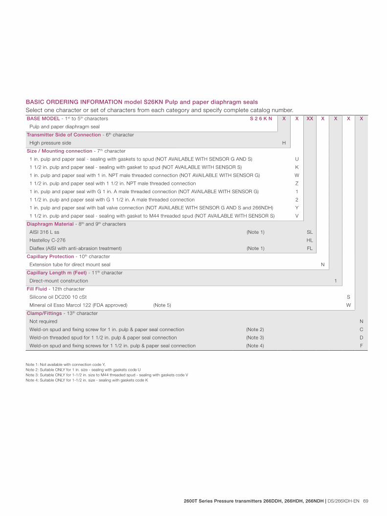
2600T Series Pressure transmitters 266DDH, 266HDH, 266NDH | DS/266XDH-EN 69
BASIC ORDERING INFORMATION model S26KN Pulp and paper diaphragm sealsSelect one character or set of characters from each category and specify complete catalog number.BASE MODEL - 1st to 5th characters S 2 6 K N X X XX X X X X
Pulp and paper diaphragm seal
Transmitter Side of Connection - 6th character
High pressure side H
Size / Mounting connection - 7th character
1 in. pulp and paper seal - sealing with gaskets to spud (NOT AVAILABLE WITH SENSOR G AND S) U
1 1/2 in. pulp and paper seal - sealing with gasket to spud (NOT AVAILABLE WITH SENSOR S) K
1 in. pulp and paper seal with 1 in. NPT male threaded connection (NOT AVAILABLE WITH SENSOR G) W
1 1/2 in. pulp and paper seal with 1 1/2 in. NPT male threaded connection Z
1 in. pulp and paper seal with G 1 in. A male threaded connection (NOT AVAILABLE WITH SENSOR G) 1
1 1/2 in. pulp and paper seal with G 1 1/2 in. A male threaded connection 2
1 in. pulp and paper seal with ball valve connection (NOT AVAILABLE WITH SENSOR G AND S and 266NDH) Y
1 1/2 in. pulp and paper seal - sealing with gasket to M44 threaded spud (NOT AVAILABLE WITH SENSOR S) V
Diaphragm Material - 8th and 9th characters
AISI 316 L ss (Note 1) SL
Hastelloy C-276 HL
Diaflex (AISI with anti-abrasion treatment) (Note 1) FL
Capillary Protection - 10th character
Extension tube for direct mount seal N
Capillary Length m (Feet) - 11th character
Direct-mount construction 1
Fill Fluid - 12th character
Silicone oil DC200 10 cSt S
Mineral oil Esso Marcol 122 (FDA approved) (Note 5) W
Clamp/Fittings - 13th character
Not required N
Weld-on spud and fixing screw for 1 in. pulp & paper seal connection (Note 2) C
Weld-on threaded spud for 1 1/2 in. pulp & paper seal connection (Note 3) D
Weld-on spud and fixing screws for 1 1/2 in. pulp & paper seal connection (Note 4) F
Note 1: Not available with connection code Y,Note 2: Suitable ONLY for 1 in. size - sealing with gaskets code UNote 3: Suitable ONLY for 1-1/2 in. size to M44 threaded spud - sealing with gaskets code VNote 4: Suitable ONLY for 1-1/2 in. size - sealing with gaskets code K
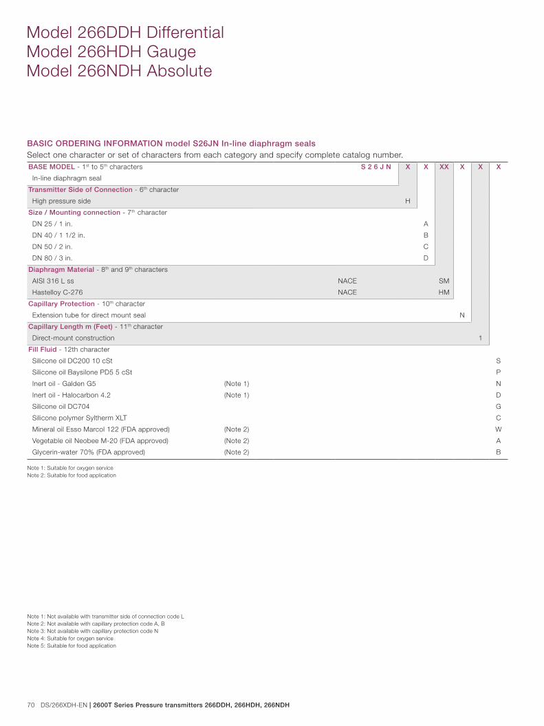
70 DS/266XDH-EN | 2600T Series Pressure transmitters 266DDH, 266HDH, 266NDH
Model 266DDH Differential Model 266HDH Gauge Model 266NDH Absolute
BASIC ORDERING INFORMATION model S26JN In-line diaphragm sealsSelect one character or set of characters from each category and specify complete catalog number.BASE MODEL - 1st to 5th characters S 2 6 J N X X XX X X X
In-line diaphragm seal
Transmitter Side of Connection - 6th character
High pressure side H
Size / Mounting connection - 7th character
DN 25 / 1 in. A
DN 40 / 1 1/2 in. B
DN 50 / 2 in. C
DN 80 / 3 in. D
Diaphragm Material - 8th and 9th characters
AISI 316 L ss NACE SM
Hastelloy C-276 NACE HM
Capillary Protection - 10th character
Extension tube for direct mount seal N
Capillary Length m (Feet) - 11th character
Direct-mount construction 1
Fill Fluid - 12th character
Silicone oil DC200 10 cSt S
Silicone oil Baysilone PD5 5 cSt P
Inert oil - Galden G5 (Note 1) N
Inert oil - Halocarbon 4.2 (Note 1) D
Silicone oil DC704 G
Silicone polymer Syltherm XLT C
Mineral oil Esso Marcol 122 (FDA approved) (Note 2) W
Vegetable oil Neobee M-20 (FDA approved) (Note 2) A
Glycerin-water 70% (FDA approved) (Note 2) B
Note 1: Suitable for oxygen serviceNote 2: Suitable for food application
Note 1: Not available with transmitter side of connection code LNote 2: Not available with capillary protection code A, BNote 3: Not available with capillary protection code NNote 4: Suitable for oxygen serviceNote 5: Suitable for food application
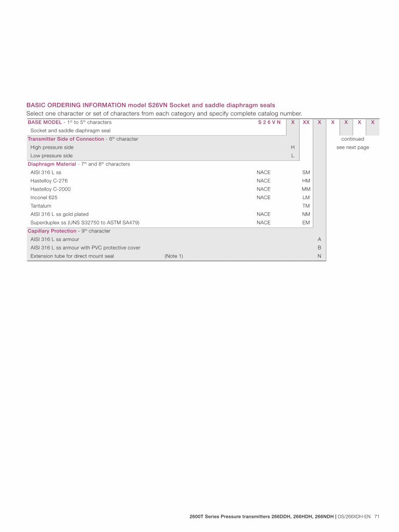
2600T Series Pressure transmitters 266DDH, 266HDH, 266NDH | DS/266XDH-EN 71
BASIC ORDERING INFORMATION model S26VN Socket and saddle diaphragm sealsSelect one character or set of characters from each category and specify complete catalog number.BASE MODEL - 1st to 5th characters S 2 6 V N X XX X X X X X
Socket and saddle diaphragm seal
Transmitter Side of Connection - 6th character continued
see next pageHigh pressure side H
Low pressure side L
Diaphragm Material - 7th and 8th characters
AISI 316 L ss NACE SM
Hastelloy C-276 NACE HM
Hastelloy C-2000 NACE MM
Inconel 625 NACE LM
Tantalum TM
AISI 316 L ss gold plated NACE NM
Superduplex ss (UNS S32750 to ASTM SA479) NACE EM
Capillary Protection - 9th character
AISI 316 L ss armour A
AISI 316 L ss armour with PVC protective cover B
Extension tube for direct mount seal (Note 1) N
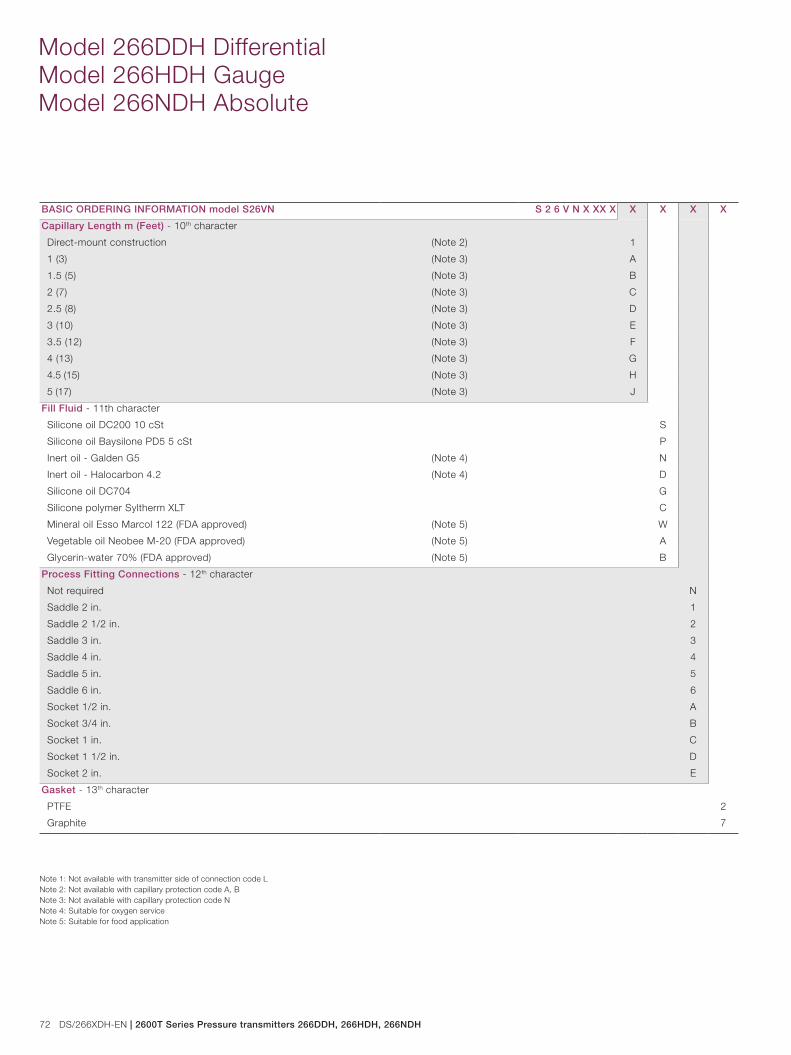
72 DS/266XDH-EN | 2600T Series Pressure transmitters 266DDH, 266HDH, 266NDH
Model 266DDH Differential Model 266HDH Gauge Model 266NDH Absolute
BASIC ORDERING INFORMATION model S26VN S 2 6 V N X XX X X X X X
Capillary Length m (Feet) - 10th character
Direct-mount construction (Note 2) 1
1 (3) (Note 3) A
1.5 (5) (Note 3) B
2 (7) (Note 3) C
2.5 (8) (Note 3) D
3 (10) (Note 3) E
3.5 (12) (Note 3) F
4 (13) (Note 3) G
4.5 (15) (Note 3) H
5 (17) (Note 3) J
Fill Fluid - 11th character
Silicone oil DC200 10 cSt S
Silicone oil Baysilone PD5 5 cSt P
Inert oil - Galden G5 (Note 4) N
Inert oil - Halocarbon 4.2 (Note 4) D
Silicone oil DC704 G
Silicone polymer Syltherm XLT C
Mineral oil Esso Marcol 122 (FDA approved) (Note 5) W
Vegetable oil Neobee M-20 (FDA approved) (Note 5) A
Glycerin-water 70% (FDA approved) (Note 5) B
Process Fitting Connections - 12th character
Not required N
Saddle 2 in. 1
Saddle 2 1/2 in. 2
Saddle 3 in. 3
Saddle 4 in. 4
Saddle 5 in. 5
Saddle 6 in. 6
Socket 1/2 in. A
Socket 3/4 in. B
Socket 1 in. C
Socket 1 1/2 in. D
Socket 2 in. E
Gasket - 13th character
PTFE 2
Graphite 7
Note 1: Not available with transmitter side of connection code LNote 2: Not available with capillary protection code A, BNote 3: Not available with capillary protection code NNote 4: Suitable for oxygen serviceNote 5: Suitable for food application


DS
/266
XD
H-E
N 1
2.20
10
Contact us
NoteWe reserve the right to make technical changes or modify the contents of this document without prior notice. With regard to purchase orders, the agreedparticulars shall prevail. ABB does not accept any responsibility whatsoever for potential errors or possible lack of information in this document.
We reserve all rights in this document and in the subject matter and illustrations contained therein. Any reproduction, disclosure to third parties or utilization of its contents - in whole or in parts – is forbidden without prior written consent of ABB.
Copyright© 2010 ABBAll rights reserved
3KXP200017R1001
™ Hastelloy C-276 is a Cabot Corporation trademark™ Hastelloy C-2000 is an Haynes International trademark™ Monel is an International Nickel Co. trademark™ Viton is a Dupont de Nemour trademark™ DC200 is a Dow Corning Corporation trademark™ DC704 is a Dow Corning Corporation trademark™ Galden is a Montefluos trademark ™ Halocarbon is a Halocarbon Products Co. trademark™ Baysilone is a GE Bayer trademark ™ Neobee M-20 is a Stepan Company trademark™ Esso Marcol 122 is a Esso Italiana trademark™ Syltherm is a Dow Chemical Company trademark
ABB Ltd. Process AutomationHoward RoadSt. NeotsCambridgeshire PE19 8EU UKTel: +44 (0)1480 475321Fax: +44 (0)1480 217948
ABB Inc.Process Automation125 E. County Line RoadWarminster PA 18974USATel: +1 215 674 6000Fax: +1 215 674 7183
ABB Automation Products GmbHProcess AutomationSchillerstr. 7232425 MindenGermanyTel: +49 551 905 534Fax: +49 551 905 555
ABB S.p.A. Process AutomationVia Statale 11322016 Lenno (CO)ItalyTel: +39 0344 58111Fax: +39 0344 56278
www.abb.com