Model 2192 Master Audio Interfacemedia.uaudio.com/assetlibrary/2/1/2192_manual.pdf · Thank you for...
55
Model 2192 Master Audio Interface Universal Audio Part Number 65-00036 Universal Audio, Inc. Customer Service & Tech Support: 1-877-MY-AUDIO Business, Sales & Marketing: 1-866-UAD-1176 www.uaudio.com FCC Compliance This equipment has been tested and found to comply with the limits for a Class B digital device, pursuant to part 15 of the FCC Rules. These limits are designed to provide reasonable protection against harmful interference in a residential installation.
Transcript of Model 2192 Master Audio Interfacemedia.uaudio.com/assetlibrary/2/1/2192_manual.pdf · Thank you for...

Model 2192 Master Audio Interface
Universal Audio Part Number 65-00036
Universal Audio, Inc.
Customer Service & Tech Support: 1-877-MY-AUDIO Business, Sales & Marketing: 1-866-UAD-1176
www.uaudio.com
FCC Compliance
This equipment has been tested and found to comply with the limits for a Class B digital device, pursuant to part 15 of the FCC Rules. These limits are designed to provide reasonable protection against harmful interference in a residential installation.

This equipment generates, uses and can radiate radio frequency energy and, if not installed and used in accordance with the instructions, may cause harmful interference to radio communications. However, there is no guarantee that interference will not occur in a particular installation.
If this equipment does cause harmful interference to radio or television reception, which can be determined by turning the equipment off and on, the user is encouraged to try to correct the interference by one or more of the following measures:
• Reorient or relocate the receiving antenna. • Increase the separation between the equipment and receiver. • Connect the equipment into an outlet on a circuit different from that to which the receiver is
connected. • Consult the dealer or an experienced radio/TV technician for help.
Caution: Changes or modifications not expressly approved by Universal Audio could void the user’s authority to operate the equipment.
Notice
This manual provides general information, preparation for use, installation and operating instructions for the Universal Audio 2192.
The information contained in this manual is subject to change without notice. Universal Audio, Inc. makes no warranties of any kind with regard to this manual, including, but not limited to, the implied warranties of merchantability and fitness for a particular purpose. Universal Audio, Inc. shall not be liable for errors contained herein or direct, indirect, special, incidental, or consequential damages in connection with the furnishing, performance, or use of this material.
Copyright
© 2008 Universal Audio, Inc. All rights reserved.
This manual and any associated software, artwork, product designs, and design concepts are subject to copyright protection. No part of this document may be reproduced, in any form, without prior written permission of Universal Audio, Inc.
Trademarks
2192, 1176LN, 2-1176, 6176, LA-2A, 2-LA2, LA-610, LA-3A, 2-610, 710, 4110, 8110, SOLO/110, SOLO/610, DCS Remote Preamp, UAD and the Universal Audio, Inc. logo are trademarks of Universal Audio, Inc. ADAT® is a registered trademark of Alesis Corporation. Other company and product names mentioned herein are trademarks of their respective companies.
Contents of This Box
This package should contain:
• One Model 2192 Master Audio Interface • 2192 Operating Instructions • IEC Power Cable
A Letter From Bill Putnam, Jr. __________________________________________________________
- i -
Thank you for purchasing the Model 2192 Master Audio Interface, the first product to combine Universal Audio’s long history of high-quality vintage analog gear with advanced digital technology.
The 2192 is the perfect two-channel master audio interface for every digital studio. It performs both analog to digital (A/D) and digital to analog (D/A) conversion and provides a high-quality master clock source and clock distribution for your entire studio. The internal digital clock of the 2192 was designed for extreme stability and jitter-free operation, and its onboard phase aligned clock conditioner circuitry removes jitter from external sources, so conversion quality is unaffected by clock source. Two separate word clock inputs are provided, as well as AES/EBU, S/PDIF, and ADAT S-MUX inputs, and any of these can be used as external clock sources. Four parallel word clock outputs allow the 2192 to be used as a master clock source without the need to daisy-chain or cascade the clock through external devices.
The heart and soul of the 2192 is the analog circuitry used in its A/D and D/A converters. The analog signal path uses DC-coupled, fully dual-differential, matched-FET, all discrete Class-A circuitry, resulting in ultra-low noise, excellent transient response, and unmatched sound. No capacitors or DC servos are used in the signal path since these degrade audio quality and image stability and introduce phase distortion. Our no-compromise approach and extensive history in analog and digital circuit design ensure that your converted signals are totally accurate and of the highest possible fidelity.
Analog signals are converted to digital in full 24-bit format, at sampling rates of up to 192kHz. During A/D conversion, the digital signal is output to all digital outputs (AES/EBU, S/PDIF, or ADAT S-MUX) simultaneously. Audio digitized at sample rates of 176.4 or 192kHz is carried over AES/EBU in single- or dual-wire mode, and ADAT optical I/O utilizes S-MUX interleaving. The S/PDIF specification, which includes 192kHz 24-bit audio, is fully implemented. The 2192 D/A converters can also be set to output the signal directly from the A/D converters, thus enabling “true confidence” analog monitoring of the digitized signal.
Digital to analog conversion is supported just as comprehensively. Any of the 2192 digital input sources can be converted to analog, with selectable clock source: internal clock, the digital audio source signal, or an external clock source separate from the digital audio. D/A conversion is always accomplished at the sample rate of the digital audio source signal, even if the 2192 is synchronized to an external clock source that is running at a multiple or submultiple of the digital audio sample rate. The 2192 can also transcode (convert) digital audio between AES/EBU, S/PDIF, and ADAT S-MUX in real time, using any of the available clock sources. Multi-segment LED bargraph metering is provided for all analog inputs and outputs, with timed peak-hold digital overload (input) and digital peak (output) indicators. Finally, an internal universal auto-sensing, filtered, multi-stage regulated power supply supports 100-240VAC and 50-60Hz power for trouble-free operation world-wide.
Most of us at Universal Audio are musicians and/or recording engineers. We love the recording process, and we really get inspired when tracks are beautifully recorded. Developing the Model 2192—as well as Universal Audio’s entire line of quality digital and analog audio products designed to meet the needs of the modern recording studio while retaining the character of classic vintage equipment—has been a very special experience for me and for all who have been involved. While, on the surface, the rebuilding of UA has been a business endeavor, it’s really been so much more than that: in equal parts a sentimental and technical adventure.
We thank you, and we thank my father, Bill Putnam.
Sincerely,
Bill Putnam, Jr.
Important Safety Instructions ___________________________________________________________
- ii -
Before using this unit, be sure to carefully read the applicable items of these operating instructions and the safety suggestions. Afterwards, keep them handy for future reference. Take special care to follow the warnings indicated on the unit, as well as in the operating instructions.
1. Water and Moisture - Do not use the unit near any source of water or in excessively moist environments. 2. Object and Liquid Entry - Care should be taken so that objects do not fall, and liquids are not spilled, into
the enclosure through openings. 3. Ventilation - When installing the unit in a rack or any other location, be sure there is adequate ventilation.
Improper ventilation will cause overheating, and can damage the unit. 4. Heat - The unit should be situated away from heat sources, or other equipment that produce heat. 5. Power Sources - The unit should be connected to a power supply only of the type described in the
operating instructions, or as marked on the unit. 6. Power Cord Protection - AC power supply cords should be routed so that they are not likely to be walked
on or pinched by items placed upon or against them. Pay particular attention to cords at plugs, convenience receptacles, and the point where they exit from the unit. Never take hold of the plug or cord if your hand is wet. Always grasp the plug body when connecting or disconnecting it.
7. Grounding of the Plug - This unit is equipped with a 3-wire grounding type plug, a plug having a third
(grounding) pin. This plug will only fit into a grounding-type power outlet. This is a safety feature. If you are unable to insert the plug into the outlet, contact your electrician to replace your obsolete outlet. Do not defeat the purpose of the grounding-type plug.
8. Cleaning - Follow these general rules when cleaning the outside of your 2192:
a. Turn the power Off and unplug the unit b. Gently wipe with a clean lint-free cloth c. If necessary, moisten the cloth using lukewarm or distilled water, making sure not to oversaturate it
as liquid could drip inside the case and cause damage to your 2192 d. Use a dry lint-free cloth to remove any remaining moisture e. Do not use aerosol sprays, solvents, or abrasives
9. Nonuse Periods - The AC power supply cord of the unit should be unplugged from the AC outlet when left
unused for a long period of time. 10. Damage Requiring Service - The unit should be serviced by a qualified service personnel when:
a. The AC power supply cord or the plug has been damaged: or b. Objects have fallen or liquid has been spilled into the unit; or c. The unit has been exposed to rain; or d. The unit does not operate normally or exhibits a marked change in performance; or e. The unit has been dropped, or the enclosure damaged.
11. Servicing - The user should not attempt to service the unit beyond that described in the operating
instructions. All other servicing should be referred to qualified service personnel.

Table of Contents __________________________________________________________
A Letter From Bill Putnam, Jr. ..................................................................................................................
Important Safety Instructions .................................................................................................................
Two Page, Two Minute Guide To Getting Started ......................................................................................
Front Panel ...............................................................................................................................................
Rear Panel ................................................................................................................................................
Interconnections ..................................................................................................................................... Typical Mastering Setup ........................................................................................................... Typical DAW Setup ..................................................................................................................... Typical 8-Track Pro Tools HD Setup ..................................................................................................
Applications .............................................................................................................................................. Analog to Digital Conversion ......................................................................................................
A/D Conversion Using Internal Clock .................................................................... A/D Conversion Using External Clock .......................................................................
Digital to Analog Conversion ...................................................................................................... D/A Conversion Using Internal Clock ................................................................... D/A Conversion Using Digital Audio Source Clock ................................................. D/A Conversion Using External Word Clock ............................................................ D/A Conversion of AES/SPDIF Audio Using ADAT Clock ....................................... D/A Conversion of ADAT Audio Using AES/SPDIF Clock ........................................
Transcoding (Converting Digital Formats) ................................................................................. Transcoding Using Internal Clock ........................................................................... Transcoding Using Digital Audio Source Clock ...................................................... Transcoding Using Alternate Clock .......................................................................
The Technical Stuff ................................................................................................................................ History of the 2192 ................................................................................................................... Digital Audio Clocking Primer ...................................................................................................
2192 Overview ............................................................................................................................. 2192 Circuitry ............................................................................................................................. Maintenance Information........................................................................................................... Line Trim Procedure ................................................................................................... Output Level Meter Calibration .........................................................................................
Ground Isolation Jumpers / Fuse / Voltage Selector ...................................................... Block Diagram ............................................................................................................................ Dynamic Range and Frequency Response Diagrams ...................................................................
Glossary of Terms ..................................................................................................................................
Recall Sheet .............................................................................................................................................
Specifications ........................................................................................................................................ Additional Resources / Product Registration / Warranty / Service & Support
..................................................................................................... Inside back cover
i
ii
2
4
9
12 12 12 13
14 14 15 16 17 17 18 19 20 21 22 22 23 24
25 25 26 28 32 35 35 36 38 39 40
42
46
47

The Two Page, Two Minute Guide To Getting Started __________________________________________________________
- 2 -
No one likes to read owner’s manuals. We know that. We also know that you know what you’re doing—why else would you have bought our product? So we’re going to try to make this as easy on you as possible. Hence this two-page spread, which we estimate will take you approximately two minutes to read. It will tell you everything you need to know to get your Universal Audio 2192 up and running, without bogging you down with details. Of course, even the most expert of us has to crack a manual every once in awhile. As the saying goes, “as a last resort, read the instructions.” You’ll find those details you’re craving—a full description of all front and rear panel controls, interconnection diagrams, history, theory, maintenance information, block diagrams, specifications, even a glossary of terms—in the pages that follow. Getting Started With Your 2192: Step 1: Decide where the 2192 is to be physically placed and place it there. The 2192 is housed in a standard single-rackspace 19" chassis, and so we recommend that it be securely mounted in a rack if possible. Because it can run hot, be sure the 2192 side ventilation panels are not blocked. We also recommend leaving at least a single empty rack space above and below the 2192 for adequate ventilation.
Step 2: Mute your monitors and then, using a balanced cable with XLR connectors, connect the 2192’s rear panel analog line inputs and outputs to the appropriate inputs and outputs on your patch bay, mixer, or DAW.
Step 3: Using the appropriate digital cables, make interconnections between the 2192’s rear panel
digital inputs and outputs (word clock, AES, SPDIF, and/or ADAT) and compatible digital hardware in
your studio. (see pages 12 - 13 for suggested interconnection diagrams) Step 4: Make sure the Power switch is off (down position) and then connect the supplied IEC power cable to the rear panel AC power connector.
Manual conventions:
Means that this is an especially useful tip
Means that this is an especially important bit of information And when we need to direct you to a page or section elsewhere in the manual, we’ll use the universal signs
for rewind () or fast forward ()
Mute your monitoring system before applying power to the 2192 and interconnecting it with other equipment.

The Two Page, Two Minute Guide To Getting Started __________________________________________________________
- 3 -
Step 5: In addition to providing a high-quality master clock for your entire studio (or distributing an external clock to your digital equipment), the 2192 can be used for a variety of functions, including analog to digital (A/D) conversion, digital to analog (D/A) conversion, and transcoding (converting between different digital formats). Detailed instructions are given on pages 15 - 24 in this owners manual for each application. Refer to the list below for step-by-step directions in setting up your 2192 and interconnected equipment for each of these functions:
• A/D Conversion Using Internal Clock - page 15 • A/D Conversion Using External Clock - page 16 • D/A Conversion Using Internal Clock - page 17 • D/A Conversion Using Digital Audio Source Clock - page 18 • D/A Conversion Using External Word Clock - page 19 • D/A Conversion of AES/SPDIF Audio Using ADAT Clock - page 20 • D/A Conversion of ADAT Audio Using AES/SPDIF Clock - page 21 • Transcoding Using Internal Clock - page 22 • Transcoding Using Digital Audio Source Clock - page 23 • Transcoding Using Alternate Clock - page 24
Step 6: Power on the 2192. After a delay of approximately 2 seconds (during which the 2192 power conditioner circuits perform their initial calibrations), the Power lamp (immediately above the Power switch) will light blue and the Clock Status lamp will light green (if the 2192 is successfully locked to the selected clock source) or red (if unlocked). Step 7: Unmute your monitors and, at the source device, slowly raise the level of the selected input signal. You should now be hearing signal, with the 2192 input and output meters becoming active. Step 8: Experiment with different front panel switch and knob settings until you are familiar with their operation and functionality. You’ll undoubtedly discover lots of new uses for your 2192!
For more information, refer to the “Front Panel” and “Rear Panel” sections on pages 4 - 11 of this manual.
Because signals are briefly interrupted when new settings are applied, do not change any front panel knob or switch settings during recording or whenever conversion or transcoding is actively occurring.
The 2192 does not have a master volume control, therefore you must connect it to a mixer or other device that has a volume control.
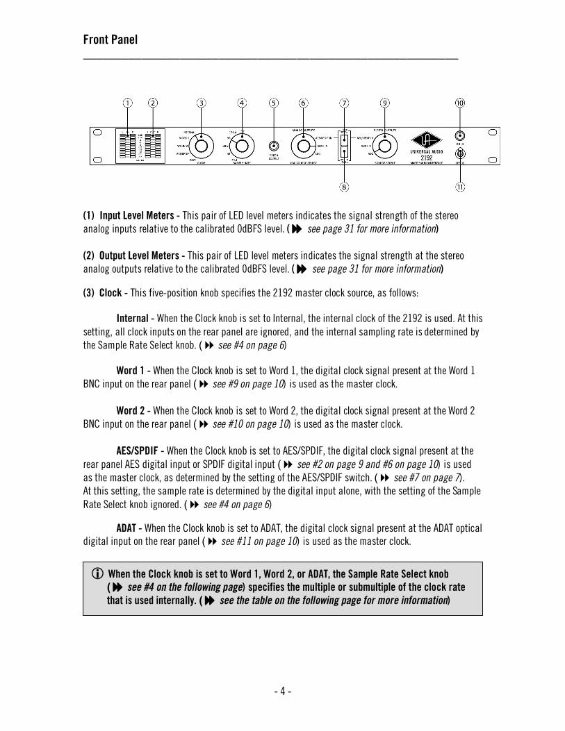
Front Panel __________________________________________________________
- 4 -
(1) Input Level Meters - This pair of LED level meters indicates the signal strength of the stereo
analog inputs relative to the calibrated 0dBFS level. ( see page 31 for more information)
(2) Output Level Meters - This pair of LED level meters indicates the signal strength at the stereo
analog outputs relative to the calibrated 0dBFS level. ( see page 31 for more information) (3) Clock - This five-position knob specifies the 2192 master clock source, as follows:
Internal - When the Clock knob is set to Internal, the internal clock of the 2192 is used. At this
setting, all clock inputs on the rear panel are ignored, and the internal sampling rate is determined by
the Sample Rate Select knob. ( see #4 on page 6)
Word 1 - When the Clock knob is set to Word 1, the digital clock signal present at the Word 1
BNC input on the rear panel ( see #9 on page 10) is used as the master clock.
Word 2 - When the Clock knob is set to Word 2, the digital clock signal present at the Word 2
BNC input on the rear panel ( see #10 on page 10) is used as the master clock.
AES/SPDIF - When the Clock knob is set to AES/SPDIF, the digital clock signal present at the
rear panel AES digital input or SPDIF digital input ( see #2 on page 9 and #6 on page 10) is used
as the master clock, as determined by the setting of the AES/SPDIF switch. ( see #7 on page 7).
At this setting, the sample rate is determined by the digital input alone, with the setting of the Sample
Rate Select knob ignored. ( see #4 on page 6)
ADAT - When the Clock knob is set to ADAT, the digital clock signal present at the ADAT optical
digital input on the rear panel ( see #11 on page 10) is used as the master clock.
When the Clock knob is set to Word 1, Word 2, or ADAT, the Sample Rate Select knob
( see #4 on the following page) specifies the multiple or submultiple of the clock rate
that is used internally. ( see the table on the following page for more information)
Front Panel __________________________________________________________
- 5 -
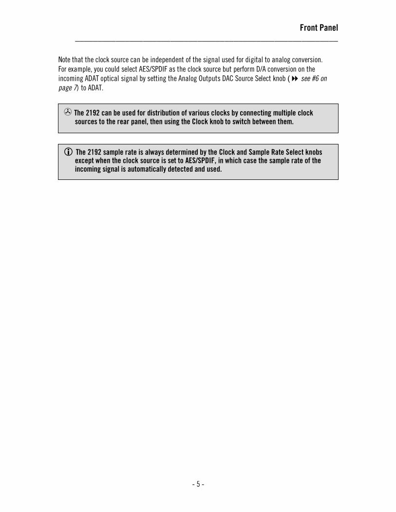
Note that the clock source can be independent of the signal used for digital to analog conversion.
For example, you could select AES/SPDIF as the clock source but perform D/A conversion on the
incoming ADAT optical signal by setting the Analog Outputs DAC Source Select knob ( see #6 on
page 7) to ADAT.
The 2192 sample rate is always determined by the Clock and Sample Rate Select knobs except when the clock source is set to AES/SPDIF, in which case the sample rate of the incoming signal is automatically detected and used.
The 2192 can be used for distribution of various clocks by connecting multiple clock
sources to the rear panel, then using the Clock knob to switch between them.

Front Panel __________________________________________________________
- 6 -
(4) Sample Rate Select - This six-position knob selects the sample rate used for A/D and D/A conversion. Sample rates of 44.1, 48, 88.2, 96, 176.4, and 192kHz are all supported by the 2192.
The function of the Sample Rate Select knob varies according to the setting of the Clock knob.
(see #3 on page 4)
• When the Clock knob is set to Internal, the Sample Rate Select knob determines the master clock frequency.
• When the Clock knob is set to AES/SPDIF, the Sample Rate Select knob has no effect. (The 2192 automatically detects and uses the sample rate of the incoming AES or SPDIF signal.)
• When the Clock knob is set to Word 1, Word 2, or ADAT, the 2192 sample rate is defined by a combination of the external clock rate and the Sample Rate Select knob. In this mode, the Sample Rate Select knob selects a multiple or submultiple of the external clock rate, as follows:
When the external And the Sample Rate The 2192 clock rate is: knob is set to: sample rate is:
44.1 kHz 44.1 or 48 44.1 kHz (1 x external clock)
44.1 kHz 88.2 or 96 88.2 kHz (2 x external clock)
44.1 kHz 176.4 or 192 176.4 kHz (4 x external clock)
48 kHz 44.1 or 48 48 kHz (1 x external clock)
48 kHz 88.2 or 96 96 kHz (2 x external clock)
48 kHz 176.4 or 192 192 kHz (4 x external clock)
88.2 kHz 44.1 or 48 44.1 kHz (1/2 x external clock)
88.2 kHz 88.2 or 96 88.2 kHz (1 x external clock)
88.2 kHz 176.4 or 192 176.4 kHz (2 x external clock)
96 kHz 44.1 or 48 48 kHz (1/2 x external clock)
96 kHz 88.2 or 96 96 kHz (1 x external clock)
96 kHz 176.4 or 192 192 kHz (2 x external clock)
176.4 kHz 44.1 or 48 44.1 kHz (1/4 x external clock)
176.4 kHz 88.2 or 96 88.2 kHz (1/2 x external clock)
176.4 kHz 176.4 or 192 176.4 kHz (1x external clock)
192 kHz 44.1 or 48 48 kHz (1/4 x external clock)
192 kHz 88.2 or 96 96 kHz (1/2 x external clock)
192 kHz 176.4 or 192 192 kHz (1 x external clock)
(5) Clock Status lamp - When the 2192 is locked (synchronized) to a clock source, the Clock Status
lamp glows green. The lamp glows red when the clock is not locked. The clock is always locked when
the Clock knob (see #3 on page 4) is set to Internal. For the clock to be locked when the clock
The 2192 does not perform sample rate conversion!
When AES/SPDIF is selected as the clock source, the Sample Rate Select knob is ignored and the 2192 instead uses the sampling rate of the incoming AES or SPDIF digital signal.

Front Panel __________________________________________________________
- 7 -
source is external, a clock signal must be present at the input selected by the Clock knob. Note: After
the Power Switch is turned on, the Clock Status lamp stays off for about 12 seconds while the 2192
power conditioner and analog conversion circuits perform their initial calibrations.
(6) Analog Outputs DAC Source Select- This three-position knob specifies the digital source for the D/A converters and the analog outputs, as follows:
AES/SPDIF In - When the Analog Outputs knob is set to AES/SPDIF In, either the AES or the
SPDIF digital input signal ( see #2 on page 9 and #6 on page 10) is routed to the D/A converters
and analog outputs, depending on the position of the AES/SPDIF switch. ( see #7 below)
ADAT In - When the Analog Outputs knob is set to ADAT In, the digital signal from the ADAT
optical input ( see #11 on page 10) is routed to the D/A converters and analog outputs. The S-MUX
mode is determined by the Sample Rate Select knob. (see #4 on the previous page)
ADC - When the Analog Outputs knob is set to ADC, the signal appearing at the analog inputs
( see #13 on page 11) is routed to the analog outputs, via both the A/D converters and D/A
converters, for “true confidence” monitoring.
(7) AES/SPDIF switch - This switch specifies whether the AES or SPDIF digital inputs are used when
the Clock knob (see #3 on page 4), Analog Outputs DAC Source Select knob (see #6 above), or
Digital Outputs Source Select knob ( see #9 on page 8) is set to AES/SPDIF. When the button is
pressed in, the SPDIF input signal is used. When the button is out, the AES input signal is used. Both
the AES and SPDIF digital outputs are always active.
The clock must be locked for proper A/D and D/A conversion and for transcoding.
The 2192 cannot lock to an external device that is set to slave to the 2192!
If the clock won’t lock when the Clock knob is set to an external source, verify that the external device is connected to the proper digital input and that it is transmitting a clock signal.

Front Panel __________________________________________________________
- 8 -
(8) Single/Dual switch - The Single/Dual switch specifies whether AES/EBU Single Wire or Dual Wire
mode is used. ( see page 28 for more information) When the button is pressed in, AES/EBU Dual
Wire mode is used. When the button is out, AES/EBU Single Wire mode is used. Note: This switch has
no effect on the SPDIF input. However, the SPDIF output will transmit the same signal as the AES “A”
output. ( see #3 on page 9 and #6 on page 10)
(9) Digital Outputs Source Select - This three-position knob specifies the signal that is routed to the
digital outputs. The signal source selected here will be routed to all digital outputs (AES, SPDIF, and
ADAT optical) simultaneously. This knob is normally set to ADC during all operations except
transcoding. ( see pages 23 - 24 for more information)
AES/SPDIF In - When the Digital Outputs knob is set to AES/SPDIF In, the digital signal
arriving at the rear panel AES or SPDIF digital input ( see #3 on page 9 and #6 on page 10) is
routed to all digital outputs, as determined by the setting of the AES/SPDIF switch. (see #7
on page 7)
ADAT In - When the Digital Outputs knob is set to ADAT In, the digital signal arriving at the
rear panel ADAT optical digital input ( see #11 on page 10) is routed to all digital outputs.
ADC - When the Digital Outputs knob is set to ADC, the signals arriving at the rear panel
analog inputs ( see #13 on page 11) are converted and delivered to the digital outputs. (10) Power lamp - The Power Lamp glows blue when the proper AC voltage is connected and the power switch is in the up (I) position. Note that, after the Power Switch is turned on, the Power Lamp stays off for about two seconds while the 2192 power conditioner circuits perform their initial calibrations.
(11) Power switch - Turns the 2192 power on or off. Power is on when the switch is in the up (I)
position. Approximately two seconds after turning power on, the Power Lamp lights blue. When the
switch is down (O), AC power is completely disconnected from the internal power supply, and only the
safety ground remains connected to the chassis.
Neither the AES/SPDIF switch nor the Single/Dual switch has any effect unless the Clock, Digital Outputs Source Select, and/or Analog Outputs DAC Source Select knobs are set to AES/SPDIF.
If the Power Lamp does not come on after the initial two-second delay, check that the 2192 is connected to a 100-240VAC 50-60Hz AC power source. If the power still does not come on, it is possible that the internal protection fuse has blown, in which case the 2192 needs to be serviced by a qualified service technician.
Rear Panel __________________________________________________________
- 9 -
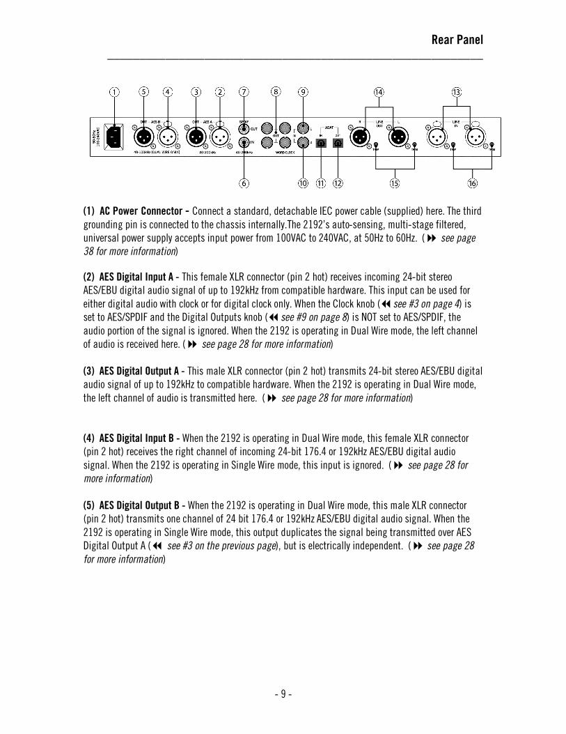
(1) AC Power Connector - Connect a standard, detachable IEC power cable (supplied) here. The third
grounding pin is connected to the chassis internally.The 2192’s auto-sensing, multi-stage filtered,
universal power supply accepts input power from 100VAC to 240VAC, at 50Hz to 60Hz. ( see page
38 for more information)
(2) AES Digital Input A - This female XLR connector (pin 2 hot) receives incoming 24-bit stereo
AES/EBU digital audio signal of up to 192kHz from compatible hardware. This input can be used for
either digital audio with clock or for digital clock only. When the Clock knob (see #3 on page 4) is
set to AES/SPDIF and the Digital Outputs knob (see #9 on page 8) is NOT set to AES/SPDIF, the
audio portion of the signal is ignored. When the 2192 is operating in Dual Wire mode, the left channel
of audio is received here. ( see page 28 for more information)
(3) AES Digital Output A - This male XLR connector (pin 2 hot) transmits 24-bit stereo AES/EBU digital
audio signal of up to 192kHz to compatible hardware. When the 2192 is operating in Dual Wire mode,
the left channel of audio is transmitted here. ( see page 28 for more information)
(4) AES Digital Input B - When the 2192 is operating in Dual Wire mode, this female XLR connector
(pin 2 hot) receives the right channel of incoming 24-bit 176.4 or 192kHz AES/EBU digital audio
signal. When the 2192 is operating in Single Wire mode, this input is ignored. ( see page 28 for
more information)
(5) AES Digital Output B - When the 2192 is operating in Dual Wire mode, this male XLR connector
(pin 2 hot) transmits one channel of 24 bit 176.4 or 192kHz AES/EBU digital audio signal. When the
2192 is operating in Single Wire mode, this output duplicates the signal being transmitted over AES
Digital Output A ( see #3 on the previous page), but is electrically independent. ( see page 28
for more information)
Rear Panel __________________________________________________________
- 10 -
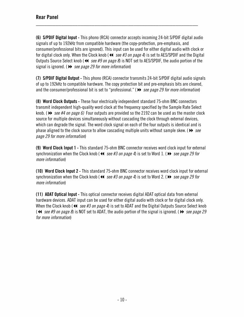
(6) S/PDIF Digital Input - This phono (RCA) connector accepts incoming 24-bit S/PDIF digital audio
signals of up to 192kHz from compatible hardware (the copy-protection, pre-emphasis, and
consumer/professional bits are ignored). This input can be used for either digital audio with clock or
for digital clock only. When the Clock knob ( see #3 on page 4) is set to AES/SPDIF and the Digital
Outputs Source Select knob ( see #9 on page 8) is NOT set to AES/SPDIF, the audio portion of the
signal is ignored. ( see page 29 for more information)
(7) S/PDIF Digital Output - This phono (RCA) connector transmits 24-bit S/PDIF digital audio signals
of up to 192kHz to compatible hardware. The copy protection bit and pre-emphasis bits are cleared,
and the consumer/professional bit is set to “professional.” ( see page 29 for more information)
(8) Word Clock Outputs - These four electrically independent standard 75-ohm BNC connectors
transmit independent high-quality word clock at the frequency specified by the Sample Rate Select
knob. ( see #4 on page 6) Four outputs are provided so the 2192 can be used as the master clock
source for multiple devices simultaneously without cascading the clock through external devices,
which can degrade the signal. The word clock signal on each of the four outputs is identical and is
phase aligned to the clock source to allow cascading multiple units without sample skew. ( see
page 29 for more information)
(9) Word Clock Input 1 - This standard 75-ohm BNC connector receives word clock input for external
synchronization when the Clock knob ( see #3 on page 4) is set to Word 1. ( see page 29 for
more information)
(10) Word Clock Input 2 - This standard 75-ohm BNC connector receives word clock input for external
synchronization when the Clock knob ( see #3 on page 4) is set to Word 2. ( see page 29 for
more information)
(11) ADAT Optical Input - This optical connector receives digital ADAT optical data from external
hardware devices. ADAT input can be used for either digital audio with clock or for digital clock only.
When the Clock knob ( see #3 on page 4) is set to ADAT and the Digital Outputs Source Select knob
( see #9 on page 8) is NOT set to ADAT, the audio portion of the signal is ignored. ( see page 29
for more information)
Rear Panel __________________________________________________________
- 11 -
(12) ADAT Optical Output - This optical connector transmits digital ADAT optical data to external
hardware devices. ( see page 29 for more information)
(13) Analog Line Inputs - Analog signals are input to the left and right channels of the 2192 A/D
converter via these balanced line-level female XLR connectors. Pin 2 is hot. For unbalanced operation,
Pin 3 can be grounded. The analog inputs are factory calibrated so that an analog input level of
+4dBu will output a -18dBFS digital signal, for 18dB of headroom before digital clipping occurs.
( see page 30 for more information)
(14) Analog Line Outputs - Analog signals are output from the left and right channels of the 2192 D/A
converter via these balanced line-level male XLR connectors. Pin 2 is hot. For unbalanced operation,
Pin 3 can be grounded, and the output level will be attenuated by 6db. The analog outputs are factory
calibrated so that a digital signal level of -18dBFS will output an analog level of +4dBu, for 18dB of
headroom. The line outputs can drive high or low (600ohm) impedance inputs with no changes in level.
( see page 30 for more information)
(15) Line Output Trims - These trims are used to calibrate the left and right analog line outputs.
( see page 35 for calibration procedures ) Differential shunt attenuation is used to maintain
maximum signal and conversion integrity. ( see pages 35 - 37 for more information)
(16) Line Input Trims - These trims are used to calibrate the left and right analog line inputs.
( see page 35 for calibration procedures ) Differential shunt attenuation is used to maintain
maximum signal and conversion integrity. ( see pages 35 - 37 for more information)

Interconnections __________________________________________________________
- 12 -
Typical Mastering Setup
Typical Digital Audio Workstation Setup
Interconnections __________________________________________________________
- 13 -
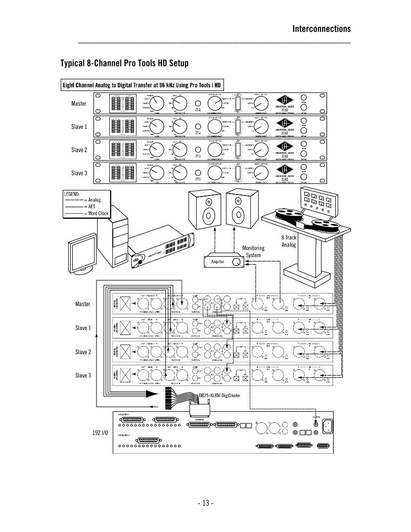
Typical 8-Channel Pro Tools HD Setup

Applications: Analog to Digital Conversion __________________________________________________________
- 14 -
Using the 2192 for Analog To Digital Conversion The 2192 enables incoming analog signals to be converted to digital, a process known as analog to digital (A/D) conversion. The resulting digital signal is always in 24-bit format, is sampled at any of six user-selectable rates (44.1, 48, 88.2, 96, 176.4, or 192kHz), and is sent to all rear panel digital outputs (AES, SPDIF, and ADAT optical) simultaneously.
• The SPDIF interface transmits 24-bit audio at rates up to 192kHz.
• Audio digitized at sample rates 44.1khz, 48kHz, and 96kHz are transmitted over AES/EBU in
Single Wire mode, as specified by the setting of the Single/Dual switch. (see #8 on page 8)
• Audio digitized at sample rates above 96k are transmitted over AES/EBU in Dual Wire mode,
as specified by the setting of the Single/Dual switch. (see #8 on page 8)
• Audio digitized at sample rates above 48kHz is transmitted over ADAT optical with S–MUX interleaving, as follows:
o At 88.2kHz and 96kHz, channels 1-4 are used for stereo audio.
o At 176.4kHz and 192kHz, all 8 channels are used for stereo audio.
When the Analog Outputs DAC Source Select knob (see #6 on page 7) is set to ADC, the signals at
the analog outs are the analog input signals after they have passed through both the A/D and D/A
converters, enabling “true confidence” analog monitoring of the digitized signal.
A/D conversion can be performed while the 2192 is using its internal clock, or when it is slaved to an external clock. Each operation is detailed on the following pages.
Because signal is briefly interrupted when new settings are applied, do not change any front panel knob or switch settings while A/D conversion is in process.
Always set the Digital Outputs Source Select knob to ADC when performing A/D conversion.

Applications: Analog to Digital Conversion __________________________________________________________
- 15 -
A/D Conversion Using Internal Clock In this configuration, the 2192 is the master system clock. Four word clock outputs are provided so the 2192 can be used as the master system clock without cascading the clock through external devices, which can degrade the clock signal. To perform A/D conversion using the internal clock:
1. Connect the analog source signals to the 2192 rear panel analog line inputs. 2. Using an appropriate digital cable, connect the 2192 rear panel digital output(s) to the
external device digital input(s) that will receive the digitized audio signal. 3. Set the 2192 Clock knob to Internal. 4. Set the 2192 Sample Rate knob to the desired frequency. 5. Set the 2192 Digital Outputs knob to ADC. 6. Set the external digital device to synchronize to the 2192 and receive the digitized audio
signal.

Applications: Analog to Digital Conversion __________________________________________________________
- 16 -
A/D Conversion Using External Clock In this configuration, the 2192 is synchronized (slaved) to an external master digital source clock. Two separate word clock inputs, as well as AES/EBU, S/PDIF, and ADAT optical, can be used as clock sources for external synchronization.
In this mode, A/D conversion is accomplished at any available 2192 sample rate, even if the external
clock is running at a multiple or submultiple of the 2192 sample rate. (see page 6 for information
on sample rate selection) To perform A/D conversion using external clock:
1. Connect the analog source signals to the 2192 rear panel analog line inputs. 2. Using an appropriate digital cable, connect the 2192 rear panel digital output(s) to the
external device digital input(s) that will receive the digitized audio signal. 3. Using an appropriate digital cable, connect the master clock source from the external device
to the 2192 digital audio or word clock input that will receive the clock signal. 4. Set the 2192 Clock knob to specify the digital input that the external clock is connected to.
If the Clock knob is set to AES/SPDIF, use the AES/SPDIF switch to specify AES or SPDIF.
5. Set the 2192 Sample Rate knob to the desired frequency. (see page 6 for information on
sample rate selection) 6. Set the 2192 Digital Outputs knob to ADC. 7. Set the external device to receive digital audio input signal. 8. Set the external master clock device to transmit digital clock.
A/D conversion is performed only when the 2192 is locked (the external clock must be running). The Locked lamp glows green when the 2192 is successfully synchronized to an external clock source.

Applications: Digital to Analog Conversion __________________________________________________________
- 17 -
Using the 2192 for Digital To Analog Conversion
The 2192 enables incoming digital signals (arriving via its rear panel AES, SPDIF, or ADAT optical
inputs) to be converted to analog, a process known as digital to analog (D/A) conversion. All 24 bits of
the digital input signal are converted, at sampling rates of 44.1, 48, 88.2, 96, 176.4, or 192kHz. If the
digital source has less than 24-bit resolution, we recommend that high quality dither be applied
before conversion.
D/A conversion can be performed while the 2192 is using its internal clock, or when it is slaved to an external clock. Each operation is detailed below and on the following pages. D/A Conversion Using Internal Clock In this configuration, the 2192 is the master system clock. Four word clock outputs are provided so the 2192 can be used as a master system clock source without cascading the clock through external devices, which can degrade the clock signal. To perform D/A conversion using the internal clock:
1. Connect the 2192 rear panel analog line outputs to the analog inputs of the destination device (patch bay, mixer, DAW, etc).
2. Using an appropriate digital cable, connect the digital output of the external digital audio
source device to the desired 2192 rear panel digital input. 3. Set the 2192 Clock knob to Internal. 4. Set the 2192 Sample Rate knob to match the sample rate of the digital audio source signal. 5. Set the 2192 Analog Outputs knob to select the digital audio source (AES/SPDIF or ADAT).
If the source is set to AES/SPDIF, use the AES/SPDIF switch to specify AES or SPDIF. 6. Set the digital audio source device to synchronize to the 2192 and transmit the digital audio
signal.
When performing D/A conversion, the 2192 sample rate must match the sample rate of the digital audio source signal.
Because the signal is briefly interrupted when new settings are applied, do not change any front panel knob or switch settings while D/A conversion is in process.
Applications: Digital to Analog Conversion __________________________________________________________
- 18 -
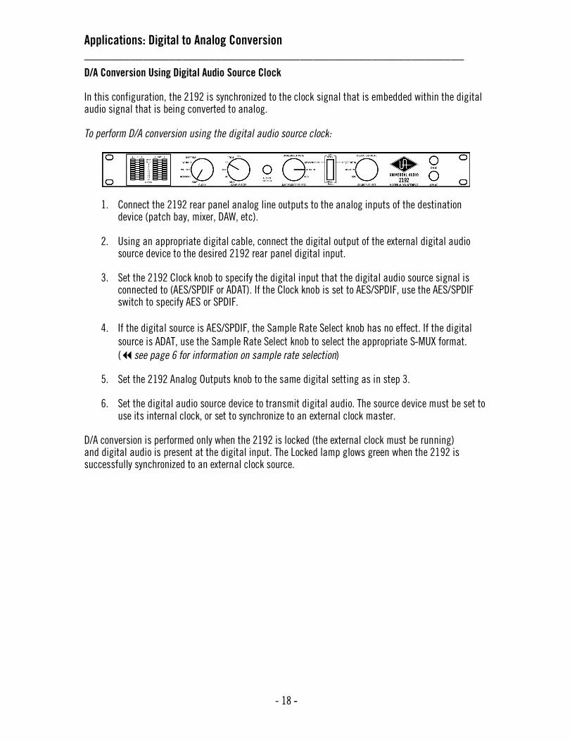
D/A Conversion Using Digital Audio Source Clock In this configuration, the 2192 is synchronized to the clock signal that is embedded within the digital audio signal that is being converted to analog. To perform D/A conversion using the digital audio source clock:
1. Connect the 2192 rear panel analog line outputs to the analog inputs of the destination device (patch bay, mixer, DAW, etc).
2. Using an appropriate digital cable, connect the digital output of the external digital audio
source device to the desired 2192 rear panel digital input. 3. Set the 2192 Clock knob to specify the digital input that the digital audio source signal is
connected to (AES/SPDIF or ADAT). If the Clock knob is set to AES/SPDIF, use the AES/SPDIF switch to specify AES or SPDIF.
4. If the digital source is AES/SPDIF, the Sample Rate Select knob has no effect. If the digital
source is ADAT, use the Sample Rate Select knob to select the appropriate S-MUX format.
(see page 6 for information on sample rate selection)
5. Set the 2192 Analog Outputs knob to the same digital setting as in step 3. 6. Set the digital audio source device to transmit digital audio. The source device must be set to
use its internal clock, or set to synchronize to an external clock master. D/A conversion is performed only when the 2192 is locked (the external clock must be running) and digital audio is present at the digital input. The Locked lamp glows green when the 2192 is successfully synchronized to an external clock source.

Applications: Digital to Analog Conversion __________________________________________________________
- 19 -
D/A Conversion Using External Word Clock In this configuration, D/A conversion is accomplished while the 2192 is synchronized to one of its two independent Word Clock inputs. To perform D/A conversion while synchronized to word clock:
1. Connect the 2192 rear panel analog line outputs to the analog inputs of the destination device (patch bay, mixer, DAW, etc).
2. Using an appropriate digital cable, connect the digital output of the external digital audio
source device to the desired 2192 rear panel digital input. 3. Using an appropriate digital BNC cable, connect the word clock output of the external master
clock source to the 2192 rear panel Word Clock input 1 (or Word Clock input 2). 4. Set the 2192 Clock knob to Word 1 (or Word 2). 5. Set the 2192 Sample Rate knob to the appropriate range to match the digital audio source
sample rate. The selected sample rate is used by all four 2192 rear panel Word Clock outputs to enable synchronization of external devices.
6. Set the 2192 Analog Outputs knob to specify the digital input that the digital audio source
signal is connected to (AES/SPDIF or ADAT). If the Analog Outputs Source Select knob is set to AES/SPDIF, use the AES/SPDIF switch to specify AES or SPDIF.
7. Set the external word clock device to transmit word clock. It can be set to transmit a multiple
or submultiple of the sample rate if necessary. For example, a 48kHz clock can be used with 96 or 192kHz digital audio and vice versa. However, a 48kHz clock cannot be used with 44.1, 88.2, or 176.4kHz digital audio.
8. Set the digital audio source device to transmit digital audio. The source device must be set to
synchronize to either the external clock master, or to the clock output of the 2192. If the digital audio sample rate is a multiple/submultiple of the external clock rate, we recommend the use of the 2192 clock output.
D/A conversion is performed only when the 2192 is locked (the word clock must be running) and digital audio is present at the digital input. The Locked lamp glows green when the 2192 is successfully synchronized to an external clock source.

Applications: Digital to Analog Conversion __________________________________________________________
- 20 -
D/A Conversion of AES/SPDIF Audio Using ADAT Clock In this configuration, an incoming AES or SPDIF digital audio signal is converted to analog while the 2192 is synchronized to the clock arriving at the ADAT input. (The audio portion [if any] of the ADAT signal is ignored.) To perform AES or SPDIF D/A while synchronized to ADAT clock:
1. Connect the 2192 rear panel analog line outputs to the analog inputs of the destination device (patch bay, mixer, DAW, etc).
2. Using an appropriate digital cable, connect the digital output of the external digital audio
source device to the 2192 ‘s AES or SPDIF digital input. 3. Using an appropriate optical cable, connect the digital output of the external ADAT device that
contains the digital clock signal to the 2192 rear panel ADAT input. 4. Set the 2192 Clock knob to ADAT. 5. Set the Sample Rate Select knob to the appropriate rate to match the AES/SPDIF digital audio
sample rate. The selected sample rate is used by all four 2192 rear panel Word Clock outputs to enable synchronization of external devices.
6. Set the 2192 Analog Outputs knob to AES/SPDIF. Use the AES/SPDIF switch to specify AES or
SPDIF. 7. Set the external ADAT device to transmit digital clock. 8. Set the AES/SPDIF source device to transmit digital audio. 9. Set the AES/SPDIF audio source device to synchronize to either the external ADAT clock master,
or to the clock output of the 2192. If the digital audio sample rate is a multiple/submultiple of the external clock rate, use the clock outputs from 2192 for the digital audio source device.
D/A conversion is performed only when the 2192 is locked (the external clock must be running) and digital audio is present at the digital input. The Locked lamp glows green when the 2192 is successfully synchronized to an external clock source.

Applications: Digital to Analog Conversion __________________________________________________________
- 21 -
D/A Conversion of ADAT Audio Using AES/SPDIF Clock In this configuration, an incoming ADAT digital audio signal is converted to analog while the 2192 is synchronized to the clock of an AES or SPDIF signal. (The audio portion [if any] of the external AES or SPDIF signal is ignored.) To perform ADAT D/A while synchronized to AES or SPDIF clock:
1. Connect the 2192 rear panel analog line outputs to the analog inputs of the destination device (patch bay, mixer, DAW, etc).
2. Using an appropriate optical cable, connect the optical output of the external ADAT digital
audio source device to the 2192 rear panel ADAT input. 3. Using an appropriate digital cable, connect the digital output of the external AES/SPDIF device
that contains the digital clock signal to the desired 2192 rear panel digital input. 4. Set the 2192 Clock knob to AES/SPDIF. Use the AES/SPDIF switch to specify AES or SPDIF. 5. The 2192 Sample Rate is defined by the AES/SPDIF digital input (the Sample Rate knob is
ignored). The selected sample rate is used by all four 2192 rear panel Word Clock outputs to enable synchronization of external devices.
6. Set the 2192 Analog Outputs knob to ADAT. 7. Set the external AES/SPDIF device to transmit digital clock. 8. Set the ADAT digital audio source device to transmit digital audio. 9. Set the ADAT audio source device to synchronize to either the external clock master, or to the
clock output of the 2192. D/A conversion is performed only when the 2192 is locked (the external clock must be running) and digital audio is present at the digital input. The Locked lamp glows green when the 2192 is successfully synchronized to an external clock source.

Applications: Transcoding __________________________________________________________
- 22 -
Using the 2192 for Transcoding (Converting Digital Formats) The 2192 can transcode (convert) digital audio data between AES/EBU, S/PDIF, and ADAT optical formats in real time. The transcoded digital audio input signal is output to all 2192 digital audio outputs simultaneously.
Transcoding can be performed using any of the available clock sources. To hear analog audio during transcoding, set the Analog Outputs knob to the digital audio source.
Transcoding can be performed using either the internal clock, the digital audio source clock, or an external clock master. Each operation is detailed below and on the following pages. Transcoding Using Internal Clock In this configuration, the 2192 is the master system clock.
To perform transcoding using the internal clock:
1. Using the appropriate digital cable, connect the digital output from the external digital audio source device to the desired 2192 digital input.
2. Using the appropriate digital cable(s), connect the 2192 digital output(s) to the digital
input(s) on any external device(s) that will receive the transcoded digital audio signal. 3. Set the 2192 Clock knob to Internal. 4. Set the 2192 Sample Rate knob to match the sample rate of the digital audio source signal. 5. Set the 2192 Digital Outputs knob to the digital audio source input (AES/SPDIF or ADAT). If the
Digital Outputs knob is set to AES/SPDIF, use the AES/SPDIF switch to specify AES or SPDIF. 6. Set the digital audio source device to transmit digital audio and to synchronize to either the
external master clock or to the 2192.
You cannot clock to S/PDIF while listening to AES/EBU or vice versa.
Because the signal is briefly interrupted when new settings are applied, do not change any front panel knob or switch settings while transcoding is in process.
The 2192 does not perform sample rate conversion.

Applications: Transcoding __________________________________________________________
- 23 -
Transcoding Using Digital Audio Source Clock In this configuration, the 2192 is synchronized to the clock signal that is embedded within the digital audio source signal that is being transcoded. To perform transcoding using the digital audio source clock:
1. Using the appropriate digital cable, connect the digital output from the external digital audio source device to the desired 2192 digital input.
2. Using the appropriate digital cable(s), connect the 2192 digital output(s) to the digital
input(s) on any external device(s) that will receive the transcoded digital audio signal. 3. Set the 2192 Clock knob to specify the digital audio source input (AES/SPDIF or ADAT). If the
Clock knob is set to AES/SPDIF, use the AES/SPDIF switch to specify AES or S/PDIF. 4. Set the 2192 Digital Outputs knob to the same digital source selected in step 3. 5. Set the digital audio source device to either it’s internal clock or a third external clock source.

Applications: Transcoding __________________________________________________________
- 24 -
Transcoding Using Alternate Clock In this configuration, the 2192 is synchronized to an external clock master. The digital audio source device can be synchronized to the same clock, or to the 2192. To perform transcoding while using an alternate source clock:
1. Using the appropriate digital cable, connect the digital output from the external digital audio source device to the desired 2192 digital input.
2. Using the appropriate digital cable(s), connect the 2192 digital output(s) to the digital
input(s) on any external device(s) that will receive the transcoded digital audio signal. 3. Using the appropriate digital cable, connect the digital output from the external device that is
generating the digital clock signal to the desired 2192 digital input. 4. Set the 2192 Clock knob to specify the digital input connected to the digital clock source
(Word 1, Word 2, AES/SPDIF or ADAT). If the Clock knob is set to AES/SPDIF, use the AES/SPDIF switch to specify AES/EBU or S/PDIF.
5. Set the 2192 Digital Outputs knob to control to specify the digital input that the digital audio
source signal is connected to (AES/SPDIF or ADAT). If the Digital Outputs knob is set to AES/SPDIF, use the AES/SPDIF switch to specify AES or S/PDIF. Note that you cannot clock to S/PDIF while listening to AES/EBU or vice versa.
6. Set the external master clock device to transmit digital clock. 7. Set the digital audio source device to transmit digital audio and to synchronize to either the
external master clock or to the 2192. Transcoding is performed only when the 2192 is locked (the external clock must be running) and digital audio is present at the digital input. The Locked lamp glows green when the 2192 is successfully synchronized to an external clock source.

The Technical Stuff __________________________________________________________
- 25 -
History of the Model 2192 In 2000, legendary audio engineer Bill Putnam Sr. was awarded a Technical Grammy for his multiple contributions to the recording industry. Highly regarded as a recording engineer, studio designer/operator and inventor, Putnam was considered a favorite of musical icons Frank Sinatra, Nat King Cole, Ray Charles, Duke Ellington, Ella Fitzgerald and many, many more. The studios he designed and operated in the 1950s and 1960s were known for their sound and his innovations were a reflection of his desire to continually push the envelope.
In addition, the companies that Putnam started—Universal Audio, Studio Electronics, and UREI—built products that are still in regular use decades after their development. In 1999, his sons Bill Jr. and James Putnam re-launched Universal Audio and merged with Kind of Loud technologies—a leading audio software company—with two goals in mind: to reproduce classic analog recording equipment designed by their father and his colleagues, and to design new recording tools in the spirit of vintage analog technology.
One of the most exciting of these new recording tools is the 2192 Master Digital Audio Interface, the first product to combine UA’s long history of creating high-quality, analog gear with its advanced digital technology. Providing two channels of analog to digital conversion, two channels of digital to analog conversion, digital format conversion, and a master word clock generator/distribution amp for an entire digital hardware array, the 2192 is the perfect front end for Pro Tools and other digital audio workstations.
While advances in digital technology have made tracking, mixing and recording a much easier experience, the sound of digital had yet to aspire to the sound of the analog recording until very recently. The 2192 was built to deliver the very best audio fidelity possible. To that end, only the highest-quality analog components are used, and all the latest advents in digital technology are supported, such as high sample rates (up to 192KHz) and full 24-bit conversion.
Today Universal Audio is bridging the worlds of vintage analog and DSP technology in a creative atmosphere where musicians, audio engineers, analog designers and DSP engineers intermingle and exchange ideas. Every project taken on by the UA team is driven by its historical roots and a desire to wed classic analog technology with the demands of the modern digital studio. The 2192 truly sounds analog, but not necessarily like tape; and yet it somehow retains the neutrality necessary for a digital converter. But it does this without the wow and flutter, phase, crosstalk, and other baggage you’d expect with tape. In the words of famed producer Eliot Mazer, “…anyone hearing a 24-bit/192kHz recording can’t believe how great it sounds. When I get music into Pro Tools|HD at 192kHz with external converters like the Universal Audio 2192, it sounds analog. Analog to me is not hearing the system, it’s music that sounds natural. I’m no longer distracted by the limitations and distortions of low sampling and bit rates.”
“…anyone hearing a 24-bit/192kHz recording
can’t believe how great it sounds. When I get
music into Pro Tools|HD at 192kHz with
external converters like the Universal Audio
2192, it sounds analog. Analog to me is not
hearing the system, it’s music that sounds
natural. I’m no longer distracted by the
limitations and distortions of low sampling
and bit rates.” — producer Elliot Mazer
The Technical Stuff __________________________________________________________
- 26 -
Digital Clocking Primer Digital clocking is a complicated issue, with a number of important aspects that are often not very well understood. First and foremost, a digital clock is used to maintain synchronization between different digital devices. There are two primary purposes for clock synchronization:
1. Digital Conversion. Analog-to-digital (A/D) conversion and digital-to-analog (D/A) conversion, as well as sample-rate conversion (sometimes known as SRC, a function not performed by the 2192), all need extremely accurate clocking in order to correctly process the digital data. A low-quality clock can degrade the signal in many ways, including loss of transparency, clarity, imaging and transient response, as well as increased noise and distortion.
2. Digital Transmission. All digital devices need accurate clocking in order to properly transfer
digital data between interconnected devices. A low-quality clock can cause data reception errors, which add distortion and noise, and if the clock isn’t synchronized correctly, samples may be dropped or repeated, resulting in audible clicks or dropouts.
Clock quality is defined two ways: First, the sample rate must match the signal. This is referred to as “sample rate synchronization.” Second, the clock signal must be stable over both short- and long-term clocking intervals. “Jitter” refers to short-term clock accuracy, and “stability” or “drift” refers to long-term clock accuracy. These terms are discussed in more detail below. Sample rate synchronization is required for proper digital transmission, and is relatively easy to maintain. Basically, there must be one and only one “clock master” for all interconnected digital devices. This is done by setting one device to “master” mode (where it synchronizes to its internal clock and transmits that clock signal) and setting every other device to “slave” mode (where it receives and synchronizes to external clock), with the appropriate clock signal routed between the master and slave devices. Keep in mind that any device, whether it’s the clock master or a slave, can send or receive data once everything is synchronized correctly. When doing digital conversion, it’s best to have the converter serve as the clock master. For example, if you’re recording, clock everything off the A/D converter. Likewise, if you’re mixing, clock everything off the D/A converter. If you’re running multiple converters, use the device with the best quality clock as master. For all-digital transfers, e.g. a digital transfer from one DAW or storage device to another, clock synchronization is maintained by simply setting up the proper master-slave relationship between devices. Digital transfers can be affected by clock jitter, but not in the same way clock jitter affects analog conversion. This is a widely misunderstood concept we’ll discuss in detail below. Clock jitter is short-term variations in the edges of a clock signal, as opposed to clock drift, which is long-term variations in the clock rate. A clock could be very stable over the long term, but still have jitter, and vice versa. Timing variations are caused by noise and/or interference. If the noise/interference is a high-frequency signal, the result is jitter, and if the noise/interference is a low-frequency signal, the result is drift. As an analogy, a car with an out of balance wheel may drive straight, but you’ll get lots of vibration (jitter); conversely, a car with a loose steering wheel might have a smooth ride, but it will drift all over the road. Clock drift affects long-term synchronization, like sound to picture, and can introduce slight pitch variations in the audio. Usually however, the drift is so slow that these pitch variations are only tiny fractions of a cent, and thus unnoticeable. Clock jitter affects digital transmission and digital conversion differently, as follows:

The Technical Stuff __________________________________________________________
- 27 -
• Clock jitter in digital transmission can be caused by a bad source clock, inferior cabling or
improper cable termination, and/or signal-induced noise (called “pattern-jitter” or “symbol-jitter.”) Digital signal formats like AES/EBU, S/PDIF, and ADAT all embed a clock in the digital signal so the receiving device can synchronize to the transmitted data bits correctly. The clock used for data recovery is extracted from the signal using a clock synchronization circuit called a phase-locked-loop (PLL). This data-recovery PLL must be designed to respond very quickly to attenuate high-frequency jitter and avoid bit errors during reception. This clock from the data-recovery PLL cannot be used to generate the clocks used for digital conversion without further clock conditioning! This is a very common design flaw in most low- and mid-range digital converters.
• Clock jitter in digital conversion is what most people refer to when they discuss jitter. It’s easily
observed in a digital signal by looking at its spectrum in the frequency domain. A jittery signal will have “side-lobes” around each frequency and/or spurious tones at random, inharmonic frequencies. Usually, the jitter will be worse with higher signal frequencies. You can test your converters by sampling a high-quality 10kHz sine wave, and viewing it in the frequency domain (available with any good wave editing software package).
All modern over-sampling digital converters require a clock (called “m-clock”) that is many times (typically several MHz) higher than the sample clock. M-clock is easy to generate when the converter is the clock master, but quite difficult to generate correctly when the converter needs to sync to an external clock. External clock typically comes from a dedicated word clock input, or is extracted from the incoming digital AES/EBU, S/PDIF or ADAT signal. Word clock cannot be used by the converters until it is multiplied up to the m-clock rate. This requires a PLL or other frequency multiplier circuit which will either be cheap and jittery, or expensive and clean, depending on who makes the converter. As we said earlier, the clock recovered from the digital inputs is unsuitable for use as the converter’s m-clock, but because it’s conveniently at the same frequency, many designers don’t bother cleaning up this signal. Since the clock recovery, clock multiplier, and clock conditioning circuitry define the jitter for analog conversion, no external clock source can clean up the jitter introduced by these circuits, regardless of how perfect the external source clock is. The best they can do is avoid making it any worse, but this is hardly worth the cost: It’s much better (and less expensive) to get a good converter than it is to try and fix a bad one with an expensive master clock. The only reason to spend money on a high-quality master clock is to ensure that multiple devices are synchronized correctly. This is essential for working with audio for film/video, or when synchronizing multiple high-quality converters. A poor master clock can also affect imaging and clarity in a multi-track environment. The 2192 provides high-quality analog conversion for recording and/or playback, master clock generation, resynchronization and distribution, and digital transcoding (format conversion). With its pristine audio path, high-quality clocking, and simple front panel controls, it makes the perfect master audio interface for every digital studio, and thus provides a very cost effective way to improve overall sound quality.

The Technical Stuff __________________________________________________________
- 28 -
Model 2192 Overview The 2192 Master Audio Interface is kind of like the Swiss Army knife of digital audio. It provides two channels of analog to digital (A/D) conversion, two channels of digital to analog (D/A) conversion, a format transcoder, and a word clock generator/distribution amplifier... all in one box. Its versatility and flexibility mean that you can easily reconfigure your entire digital studio from one central source, without the need for external software, computers, or complicated nested menu commands. These same capabilities make the 2192 an excellent front end for Pro Tools or other digital audio workstations (DAWs). The 2192 delivers superb audio fidelity thanks to its pristine Class-A analog signal path, which is completely DC-coupled and fully differential, with no capacitors or DC servos (these can degrade audio quality and image stability and introduce phase distortion). Its internal clock rivals that of the best standalone units, and even when locked to external sources, a unique clock conditioning circuit eliminates jitter injection. No matter what task you give it, the 2192 can dramatically improve your monitoring environment and/or the quality of your analog masters. As a front end for a native workstation, the 2192 provides two channels of sterling sound quality for tracking, monitoring and mastering, with full support for today’s higher sample rates of 88.2, 96, 176.4, and 192kHz. The 2192 also offers tremendous flexibility in signal routing and monitoring. You can, for example, run signal into its analog inputs, at sample rates ranging from 44.1kHz to 192kHz, and simultaneously output it to AES/EBU (Single Wire or Dual Wire), S/PDIF and ADAT (with industry standard S-MUX interleaving for sample rates above 48kHz). Its selectable output monitor allows you to monitor any of the digital inputs, or the analog input, with no interruption of the transcoding. Below is a detailed description of some of the main features of the 2192. AES/EBU Digital I/O
The AES/EBU digital interfaces of the 2192 use transformer coupled, balanced differential inputs and
outputs for maximum digital signal integrity and jitter immunity. Only the highest-grade components
are used throughout.
Each balanced AES connector can individually isolate pin 1 from ground if desired via an internal
jumper block. ( see page 38 for more information) Both channels of a stereo pair, at all supported
sample rates, can be transferred on a single cable between compatible hardware units. For
compatibility with legacy equipment, dual wire mode is supported when using sample rates of 176.4 or
192kHz. In this mode, one channel of the stereo pair is received or transmitted on each of two separate
AES digital I/O’s. Dual Wire mode is set by depressing by the Single/Dual front panel selector switch.
(see #8 on page 8)
AES output “A” is used to transfer stereo digital audio on a single cable, or one channel of the stereo
pair when in Dual Wire mode. AES output “B” carries one channel in Dual Wire mode, and replicates
AES output “A” in Single Wire mode.

The Technical Stuff __________________________________________________________
- 29 -
SPDIF Digital I/O
The 2192 accepts incoming 24-bit S/PDIF digital audio signals up to 192kHz from compatible
hardware. The copy-protection, pre-emphasis, and consumer/professional bits are ignored. The SPDIF
input can be used for either digital audio with clock or for digital clock only. When the Clock knob
(see #3 on page 4) is set to AES/SPDIF and the Digital Outputs Source Select knob (see #9 on
page 8) is NOT set to AES/SPDIF, the audio portion of the signal is ignored. ADAT Optical Digital I/O
The 2192 provides standard ADAT optical digital inputs and outputs. At sample rates of 44.1kHz and
48kHz, only channels 1 and 2 are used. At higher sample rates, industry standard S-MUX multiplexing
is used to maintain high resolution transfers at higher sampling rates. At 88.2kHz and 96kHz,
channels 1 - 4 are used to carry the stereo signal. At 176.4kHz and 192kHz, all 8 channels are used for
to carry the stereo signal. Word Clock I/O
Two separate word clock inputs and four parallel word clock outputs are provided for synchronizing
with external hardware. (see #8, #9, and #10 on page 10) Connections are via standard 75-ohm
BNC connectors. All input and output signal levels are TTL and CMOS compatible. The word clock
inputs utilize internal 75-ohm terminators and receive standard digital word clock signal for
synchronization (slaving) to external hardware devices. To sync the 2192 to an external word clock
signal, set the Clock knob ( see #3 on page 4) to Word 1 or Word 2. The 2192 supports subclock
(1/2x or 1/4x) and overclock (2x and 4x) synchronization to allow converting signals at multiples or
submultiples of the sample rate. For example, a 48kHz house sync can be used while converting at
96kHz or 192kHz. Superclock (256x) is not supported; however, vari-speed sync is supported. Clocking
Combined with its extensive digital I/O, flexible front-panel routing controls, and phase aligned clock
conditioner, the 2192 provides high-quality master clock source and clock distribution for your entire
studio. Its internal digital clock was designed for extreme stability and jitter-free operation, and an
onboard clock conditioner removes jitter from external sources, so conversion quality is unaffected by
clock source. In addition to its internal clock, two separate word clock inputs, as well as clock
embedded within incoming AES/EBU, S/PDIF, and ADAT S-MUX signals, can be used as external clock
sources. Four word clock outputs are provided so the 2192 can be used as a master clock source
without cascading the clock through external devices, which can degrade the clock signal. A prominent
front-panel “Locked” lamp indicates when the 2192 is successfully synchronized to an external clock
source. A/D and D/A conversion is accomplished at any available 2192 sample rate, even if the 2192 is
synchronized (slaved) to an external clock source that is running at a multiple (subclock) or
submultiple (overclock) of the 2192 sample rate. ( see next page for more information )

The Technical Stuff __________________________________________________________
- 30 -
Subclocking/Overclocking
Subclocking occurs if the 2192 is synchronized to an external clock that is running at 2x or 4x the
2192’s sample rate. Overclocking occurs if the 2192 is synchronized to an external clock that is
running at 1/2 or 1/4 of the 2192’s sample rate. (see page 6 for more information) The 2192 clock
can be set to internal, and the digital source device set to synchronize to the 2192 (the recommended
configuration), or the clock can be derived externally, from either the digital source device or a
dedicated clock master. When an external clock is used, both the digital source device and the 2192
must be set to synchronize to the clock master. Reclocking When an external clock is used that provides a multiple or submultiple of the digital source sample rate (e.g. a 48kHz clock master with 96kHz audio), the 2192 can slave to the clock master, and generate the required word clock output for the digital source device at the higher or lower sample rate. Because the 2192 performs clock conditioning and jitter removal on all external clock sources, there is no degradation in sound quality even when using inferior clock sources. All word clock and digital output signals are generated from the conditioned internal clock, so the 2192 can be used for reclocking poor quality external source clocks.
Analog I/O
Each balanced analog connector can individually isolate pin 1 from ground if desired via an internal
jumper block. (see page 38 for more information) The analog inputs and outputs can be adjusted
to calibrate signals for different levels as desired. ( see page 35 for calibration procedures )
Analog Line Trims
The analog line trims are used to calibrate analog I/O signal levels to match external analog hardware.
The analog I/O are calibrated at the factory so that analog levels of +4dBu correspond to -18dBFS
digital levels, for 18dB of headroom and maximum analog input and output levels of +22dB. The trims
can be adjusted to accommodate maximum levels over a wide range using the rear panel 15-turn trim
potentiometer. ( see page 35 for calibration procedures )
The 2192 does not support synchronization to clock rates that are not multiples or submultiples of the digital audio (e.g. 44.1kHz clock with 48kHz digital audio, or vice versa).
The 2192 does not do sample rate conversion.
The 2192 does not support Superclock.

The Technical Stuff __________________________________________________________
- 31 -
Metering
Level metering for each of the stereo input and output channels is provided by its own front-panel
10-segment LED display. ( see #1 and #2 on page 4) Each channel has timed peak/hold digital
clip/maximum output indicators. All LED segments except CLIP are driven by the analog metering
circuitry (the meters are tied to the converters, not the analog trims). The red CLIP indicators are
driven by the digital circuitry.
Analog Metering
The nine analog LED segments are calibrated to reflect digital signal levels. A value of 0dB on the
analog meter is equal to digital full scale code (0dBFS), which reflects an analog signal level of
+22dB (adjustable using the rear panel Analog Line Trims for each channel). ( see page 35 for
calibration procedures) An analog signal level of +4dBu at 1kHz will illuminate the -18dB segment on
the 2192 meters. Note that frequencies below 50Hz will flicker, and may not be reported correctly. Digital Clip Indicators When the red CLIP indicator illuminates, a full-scale digital signal has occurred. CLIP uses a timed peak/hold-style indicator. When a signal at or over 0dBFS occurs, the CLIP indicator will remain illuminated momentarily before being auto reset once the signal drops below 0dBFS. About “Class A” Most electronic devices can be designed in such a way as to minimize a particularly unpleasant form of distortion called crossover distortion. However, the active components in “Class A” electronic devices such as the 2192 draw current and work throughout the full signal cycle, thus eliminating crossover distortion altogether.

The Technical Stuff __________________________________________________________
- 32 -
Model 2192 Circuitry The 2192 Master Audio Interface was designed with two primary goals: the highest-quality audio fidelity and ease of use.
Specifications can be useful but are sometimes misleading because they don’t always tell the whole story. Something can look great on paper, but still sound bland. Phase and frequency response, distortion, dynamic range and linearity are important indicators, but they’re based on sine wave signals that no one listens to. Transient response in a complex, dynamic music signal is very difficult to measure because the simplistic measurement tools we have are very primitive compared to the human hearing system. Also, the behavior of a complex musical signal in a real circuit is very different from the theoretical behavior of an idealized model. This is something that Univeral Audio’s engineers have been studying extensively while designing both analog circuits and DSP systems that model them.
One of the biggest criticisms of many high-sampling rate converters is the “spectrum shift” that occurs as the sampling rate is increased. One important question to ask is, how is the low end when sampling at 192 kHz? With some converters, it sounds like you’re viewing your signal through a fixed window that slides up and down the spectrum: Either you get to hear tight bass, or good highs, but not both at once. This appears to be caused by the phase distortion in the analog high-pass and digital filters used by converters. The solution adopted by the 2192 designers was to eliminate all DC blocking capacitors and all DC-servo circuits (which are a type of high-pass filter), and to use a digital offset calibration scheme that maintains maximum headroom without capacitors or sample rate-dependent digital high-pass filters.
A very significant aspect of coupling capacitors, otherwise known as DC-blocking caps, is their low-frequency phase response. All coupling capacitors are high-pass filters, which means they introduce low-end phase distortion. Unfortunately, phase distortion is most apparent at low frequencies, and it severely affects transient response and imaging. When the beater of the kick drum hits the drumhead, the signal spikes rapidly because there is more information in that signal than most musical signals. Any smearing of that transient is heard as a lack of presence and detail, and a general “it’s not quite there” effect.
Since a 24-bit converter has a theoretical dynamic range of about -145dB, circuit noise becomes a significant issue. With a maximum output level of +22dBu, this means the circuit noise cannot exceed -123dBu. At these low levels, thermal noise becomes a dominant factor, so circuit impedances must be reduced as much as possible. This causes a problem with capacitor coupled circuits because as the resistance is lowered, the capacitors must get bigger. Capacitors have a critical influence on sound quality, and big capacitors that sound good are very expensive. The 2192 designers decided to completely eliminate all coupling capacitors in order to realize the lowest possible circuit impedances and thus the lowest noise floor.
Most UA products use custom components, and the 2192 is no exception. During the course of our testing, we realized that all the venerated high-quality IC op-amps available were simply not good enough. Even after playing some tricks to make them sound as good as possible (biasing them Class-A to eliminate crossover distortion, etc.), we couldn’t get them to sound the way we wanted, so we decided to design our own op-amps that met our sonic requirements without compromise.
Although many respected designs utilize IC op-amps, one of the biggest problems with using them in audio applications is their high open loop gain. This means you have to wrap a lot of negative feedback around them to use them at the low gains required by an analog converter. The problem with high loop gain is that

The Technical Stuff __________________________________________________________
- 33 -
errors caused by transients, overshoot, intermodulation distortion, etc. are big and must be corrected for by huge amounts of negative feedback. However, the intermediate circuit elements within the op-amp don’t get corrected immediately because these devices don’t have the required infinite frequency response assumed by the classical circuit models. To make matters worse, high loop gain requires more circuit elements to provide the added gain needed for the “corrective” negative feedback, which exacerbates the problem. It’s like throwing gasoline on a fire to put it out.
In addition, standard IC op-amps use class A/B biasing, which amplify the positive and negative half-cycles using different parts of the circuit. But because every gain stage in the 2192 is pure Class-A biased, the amplifiers are always drawing current from the power supplies, and they amplify both the positive and negative half-cycles of the signal. The Class-A “constant-current” mode means the circuit doesn’t suffer from “supply-droop” distortion when handling low frequencies and sharp transients, and there is no cross-over distortion inherent with class-AB IC op-amp designs. Our Class-A, all discrete op-amp design approach uses low-gain op-amps with matched, high precision components, and minimal component stages. We use only enough negative feedback as we need to provide stability, low output impedance, and good linearity. The goal was to have the analog signal paths (from the line-ins to the A/D converter, and from the D/A converter to the line-outs) be as good as they can be. The analog circuitry is fully DC-coupled, meaning that there are no capacitors in the signal path to introduce phase distortion, which can smear high frequencies and take the punch out of low frequencies.
The 2192 analog circuitry is also fully dual-differential, meaning that there are independent, identical circuits processing both the + and - sides of the differential signals. This reduces distortion, and improves common-mode rejection and dynamic range. It also improves imaging by eliminating cross-talk between channels. Another major factor that affects dynamic range is noise immunity. Any analog circuit that requires a low noise floor must be designed as a differential circuit so common mode noise is eliminated. We designed the 2192 to use not just fully-differential analog circuitry, but dual-differential circuitry. This means we use two fully-differential circuits for each channel of signal for even greater noise immunity.
We also use high quality field-effect transistors (FETs) with matching characteristics. FETs are a special type of transistor that share the good-sounding characteristics of both tubes (i.e., low-order, “musical” 2nd and 3rd harmonics) and standard bipolar-junction transistors or BJTs (clarity, transparency, fast transient response). If FET circuits are designed correctly, they don’t share any of the negative aspects of tube or BJT circuits (noise, harshness, slow transient response). However, if used incorrectly, FETs can be affected by a type of parasitic circuit capacitance (called the Miller Capacitance) which reduces transient and high-frequency response. We use a special biasing technique in our FET op-amps to eliminate this problem.
Another important design decision was to avoid the use of any soft clip or limiting circuitry in the 2192. Many converters that incorporate such “safety-net” approaches use variations of essentially fuzz-box circuits to round the signal so it’s already clipping when the converter clips. Unfortunately, the distortion these circuits introduce isn’t very musical. We designed the 2192 to be both as accurate as possible, and as musical as possible. These are conflicting goals at high signal levels because transients can easily overload even a “perfect” converter. This is simply because digital signals don’t have infinite headroom. This isn’t as much of a problem in analog circuits because analog clipping introduces harmonics that are usually musically related to the signal. Digital is different. Because digital signals are sampled in time, digital clipping is modulated by the sampling rate, and this introduces non-musical tones called aliasing. The problem is caused by the abrupt transition between accurate signal representation and a full-scale square wave. We call the gain region between nominal and full-scale levels the “transition” region between clean and clipping, and the way the signal approaches the impassible digital full scale level is critical for reducing aliasing and improving signal clarity. Our approach to soften digital clipping is to use what’s always worked better: the transparent compression and harmonic “bloom” that occurs naturally in low-feedback Class-A circuits. We carefully selected the

The Technical Stuff __________________________________________________________
- 34 -
bias points and signal levels of our all discrete, Class-A op-amp analog circuitry to provide the perfect transition from pristine nominal levels to hard-driven high levels so the 2192 still produces musical results before digital clipping occurs. Leaving the signal pristine until harsh clipping occurs introduces aliasing and isn’t the way audio gear is supposed to work. Artificially clipping it (because it’s going to happen eventually) isn’t any better because it eats into your headroom. We decided instead to use the transition region to maintain a musical sound while still minimizing aliasing. We calibrate the 2192 to provide 18dB of headroom in the transition region from nominal to clipping, and gradually increase the harmonic bloom and Class-A compression as the signal approaches digital clipping.
It is often necessary to synchronize to external clocks (especially in a multitrack environment), but providing high quality clock synchronization and recovery is not trivial. Worse yet, the sound quality of many converters is affected when they are synchronized to an external clock. Many converters work well when they’re the clock master, but as soon as you sync them to an external clock (even when the clocks are high quality reference), their conversion quality deteriorates. Of course, performance gets even worse when the external clocks are of poor quality. We didn’t want the 2192’s conversion quality to be dependent on the quality of any external clock sources, so we incorporated a master clock conditioning circuit to eliminate jitter injection from external sources. Happily, this circuitry also produces the highest-quality internal clock, and so the 2192 internal clock rivals the best standalone units.
Another feature of the 2192’s clock conditioner is its ability to sync to clocks that are multiples or submultiples of the sampling clock. The 2192 detects the incoming clock frequency automatically, and adjusts its internal precision clock to match that frequency. This allows the 2192 to perform analog to digital conversion at 96kHz or 192kHz using an external 48kHz house sync, while simultaneously generating a new master clock at the higher sampling rate that’s in phase with the house sync.
Last but not least, we added clock distribution to the 2192 feature set to expand its role as the center of the digital studio. Clock quality is essential for maintaining analog conversion quality, so integrating the master clock within the converter is an obvious approach; the 2192 has four dedicated BNC word clock outputs.

The Technical Stuff __________________________________________________________
- 35 -
Maintenance Information Line Trim Procedure
To calibrate the analog inputs, a digital signal meter and an accurate analog reference generator with low impedance outputs are required. To calibrate the analog outputs, a digital signal generator and an accurate analog dB level meter with balanced inputs are required.
Analog line inputs calibration procedure:
1. Connect the analog reference generator to the left analog input channel of the 2192.
2. Connect the digital output of the 2192 to the digital signal meter.
3. Set the reference generator to output a 1kHz sine wave at the desired nominal signal level. The factory setting is +4dBu.
4. Adjust the input trim until the desired RMS digital level is obtained. The factory setting is -18dBFS.
5. Repeat these steps for the right channel. Analog line outputs calibration procedure:
1. Connect the digital tone generator to a digital input of the 2192.
2. Connect the left analog output channel to the analog level meter.
3. Set the digital signal generator to output a 1kHz sine wave at the desired nominal RMS signal level. The factory setting is -18dBFS.
4. Adjust the output trim until the desired analog output level is obtained. The factory setting is +4dBu.
5. Repeat these steps for the right channel.
Before adjusting the factory calibration levels, make sure your equipment reads the current calibration values correctly! If your equipment does not match the factory settings, you will need to find out why before you proceed with recalibration.

The Technical Stuff __________________________________________________________
- 36 -
Output Level Meters Calibration Having completed the output trim procedure as described on the previous page, the output meters will need to be recalibrated. (Note that the input trims have no effect on the meters, so no calibration is needed after input trims are adjusted.) The factory default has the unit set so that a 0dBFS digital level equals an analog level of +22dB. Note that the clip indicator (top LED) is not part of metering circuit. It is controlled by the processor, and is illuminated when a digital clip occurs. It is hard wired in the unit and cannot be adjusted.
To calibrate the output level meters, a digital signal generator and an accurate analog dB level meter with balanced inputs are required, as well as a small non-conductive plastic or nylon Phillips screwdriver. Output level meters calibration procedure:
1. With the unit powered down, remove the AC line cord.
2. Place the unit on a flat, stable area and remove top cover.
3. Attach the AC line cord and power up the unit.
4. Connect the digital tone generator to the digital input of the 2192.
5. Set the digital generator to output a 1kHz sine wave at -18dB.
6. Adjust the left channel output meter using Output Meter Trim A* (see Figure 4 on the next page) so that the -18dB segment for the left channel meter just lights up.
7. Adjust the right channel output meter using Output Meter Trim B* (see Figure 4 on the next
page) so that the -18dB segment for the right channel meter just lights up. The output meters are now calibrated. * Component reference designation numbers may vary from those shown in the illustration on the following page.
Important: Because there are potentially dangerous voltages present inside the unit, as well as sensitive electronic components, meter calibration should be performed by qualified service personnel only. Use extreme caution!
!

The Technical Stuff __________________________________________________________
- 37 -
Figure 4: Output Level Meter Calibration Trimpots
Important: Do not adjust the Offset trimpots! These settings are optimized at the factory.
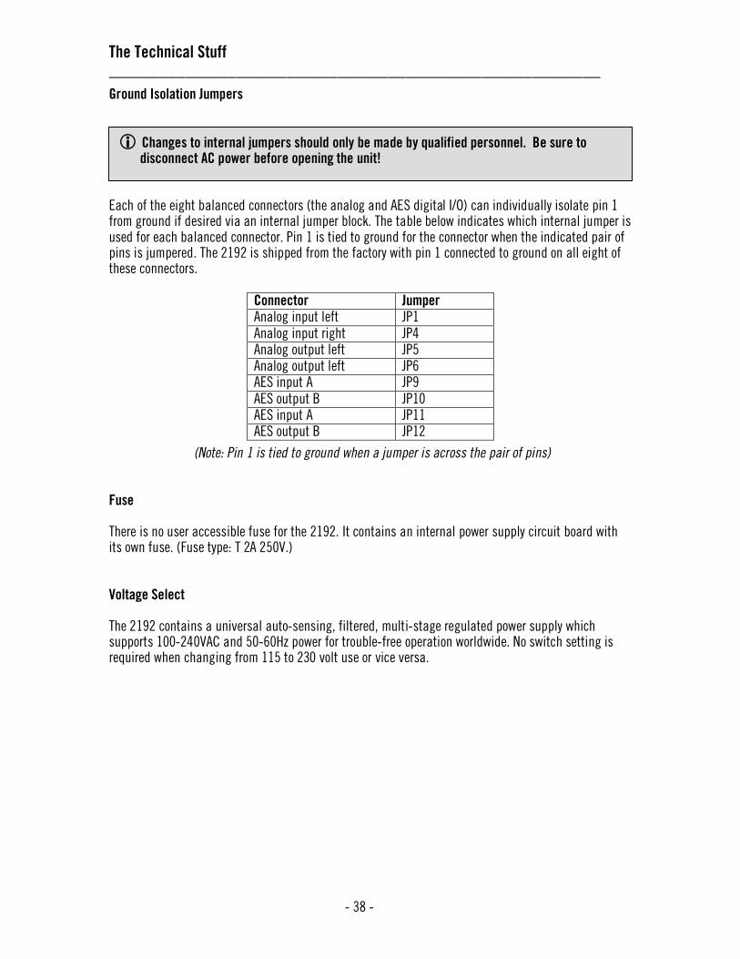
The Technical Stuff __________________________________________________________
- 38 -
Ground Isolation Jumpers
Each of the eight balanced connectors (the analog and AES digital I/O) can individually isolate pin 1 from ground if desired via an internal jumper block. The table below indicates which internal jumper is used for each balanced connector. Pin 1 is tied to ground for the connector when the indicated pair of pins is jumpered. The 2192 is shipped from the factory with pin 1 connected to ground on all eight of these connectors.
Connector Jumper
Analog input left JP1
Analog input right JP4
Analog output left JP5
Analog output left JP6
AES input A JP9
AES output B JP10
AES input A JP11
AES output B JP12
(Note: Pin 1 is tied to ground when a jumper is across the pair of pins) Fuse There is no user accessible fuse for the 2192. It contains an internal power supply circuit board with its own fuse. (Fuse type: T 2A 250V.) Voltage Select The 2192 contains a universal auto-sensing, filtered, multi-stage regulated power supply which supports 100-240VAC and 50-60Hz power for trouble-free operation worldwide. No switch setting is required when changing from 115 to 230 volt use or vice versa.
Changes to internal jumpers should only be made by qualified personnel. Be sure to disconnect AC power before opening the unit!

The Technical Stuff __________________________________________________________
- 39 -
Block Diagram
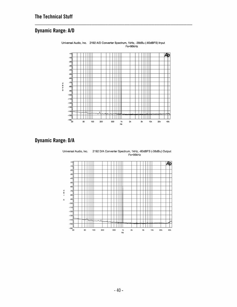
The Technical Stuff __________________________________________________________
- 40 -
Dynamic Range: A/D
Dynamic Range: D/A
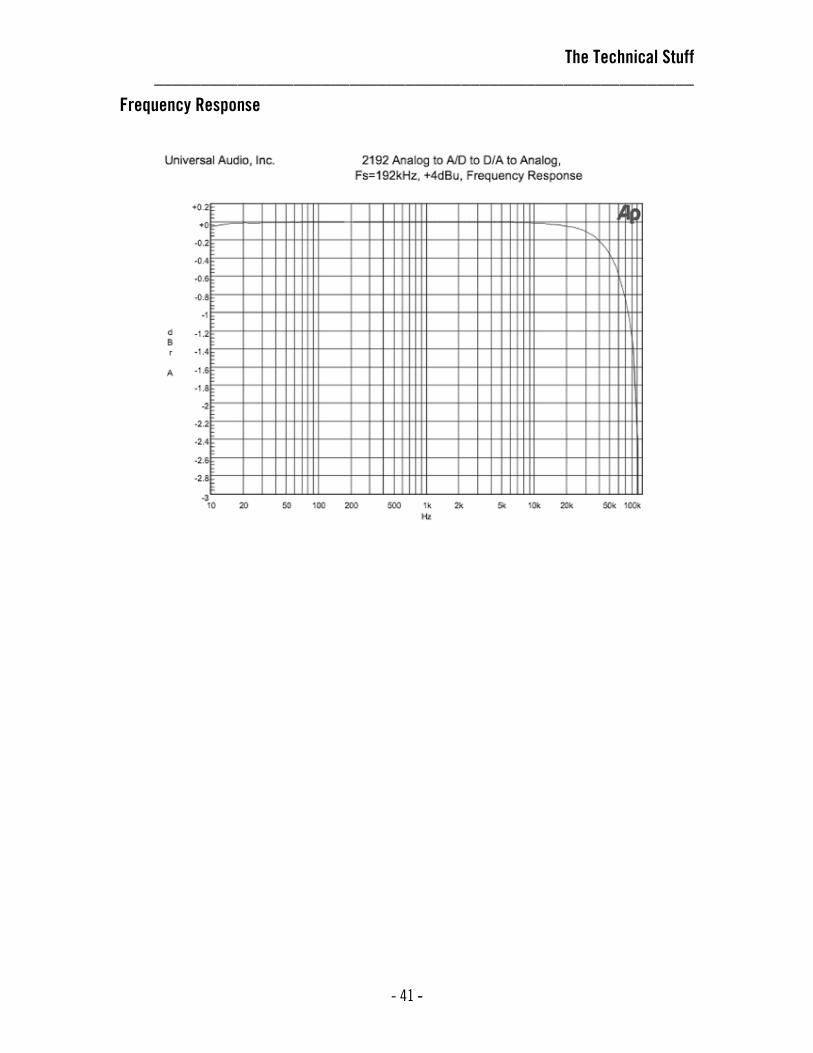
The Technical Stuff __________________________________________________________
- 41 -
Frequency Response

Glossary of Terms __________________________________________________________
- 42 -
A/D - An acronym for “Analog to Digital,” referring to the conversion of analog signal to digital.
ADAT - An acronym for “Alesis Digital Audio Tape.” ADAT was the name given to the Alesis-branded products of the 1990s which recorded eight tracks of digital audio on a standard S-VHS video cassette. The term now generally refers to the 8-channel optical connection that is used in a wide range of digital products from many manufacturers.
AES - (sometimes written as “AES/EBU”) The name of a digital audio transfer standard jointly developed by the American-based Audio Engineering Society and the European Broadcast Union. Designed to carry two channels of 16-, 20- or, 24-bit digital audio at sampling rates of up to 192kHz, the most common AES physical interconnect utilizes a 3-conductor 110 ohm twisted pair cable, terminating at standard XLR connectors. (See “Dual Wire” and “Single Wire”)
Analog - Literally, an analog is a replica or representation of something. In audio signals, changes in voltage are used to represent changes in acoustic sound pressure. Note that analog audio is a continuous representation, as opposed to the quantized, or discrete “stepped” representation created by digital devices. (See “Digital”)
Balanced - Audio cabling that uses two twisted conductors enclosed in a single shield, thus allowing relatively long cable runs with minimal signal loss and reduced induced noise such as hum.
Bit - A contraction of the words “binary” and “digit,” a bit is a number used in a digital system, and it can have only one of two values: 0 or 1. The number of bits in each sample determines the theoretical maximum dynamic range of the audio data, regardless of sample rate being used. Each additional bit adds approximately 6 dB to the dynamic range of the audio. In addition, the use of more bits helps capture quieter signal more accurately. (see “Sample” and “Dynamic range”)
Bit depth - (see “Bit resolution”)
Bit resolution - Used interchangably with “bit depth,” this is a term used to describe the number of bits used in a digital recording. The 2192 converts analog audio and transmits digital audio with a resolution of 24 bits (thus yielding a theoretical dynamic range of approximately 145 dB), the highest resolution in common use today. (see “Dynamic range”)
BNC - A bayonet-type coaxial connector often found on video and digital audio equipment, as well as on test devices like oscilliscopes. In digital audio equipment, BNC connectors are normally used to carry word clock signals between devices. BNC connectors are named for their type (Bayonet), and their inventors, Paul Neil and Carl Concelman. The 2192 provides six BNC connectors: two for word clock input, and four for word clock output. (see “Word clock”)
Class A - A design technique used in electronic devices such that their active components are drawing current and working throughout the full signal cycle, thus yielding a more linear response. This increased linearity results in fewer harmonics generated, hence lower distortion in the output signal.
Clock - In digital audio or video, a clock serves as a timing reference for a system. Every digital device must carry out specified numbers of operations per period of time and at a consistent speed in order for the device to work properly. Digital audio devices such as the 2192 normally have an internal clock, and are also capable of locking to external clock routed from other digital devices. In order to avoid signal degradation or undesirable audible artifacts, it is absolutely critical that all digital devices that are interconnected in a system be locked to the same clock. Clock distribution – Refers to the process of routing a master clock signal (either from an internal clock or an external source) to multiple devices by means of multiple outputs, thus removing the need to cascade the clock through external devices, which can degrade the signal. Clock distribution is one of the functions of the 2192.

Glossary of Terms _______________________________________________________________________
- 43 -
D/A - An acronym for “Digital to Analog,” referring to the conversion of digital signal to analog.
DAW - An acronym for “Digital Audio Workstation”—that is, any device that can record, play back, edit, and process digital audio.
dB - Short for “decibel,” a logarithmic unit of measure used to determine, among other things, power ratios, voltage gain, and sound pressure levels.
dBm - Short for “decibels as referenced to milliwatt,” dissipated in a standard load of 600 ohms. 1 dBm into 600 ohms results in 0.775 volts RMS.
dBV - Short for “decibels as referenced to voltage,” without regard for impedance; thus, one volt equals one dBV.
Digital - Information or data that is stored or communicated as a series of bits (binary digits, with values of 0 or 1). Digital audio refers to the representation of varying sound pressure levels by means of a series of numbers. (see “Analog” and “Bit”)
Dither - Minute amounts of shaped noise added intentionally to a digital recording in order to reduce a form of distortion known as “quantization noise” and aid in low level sound resolution.
DSP - An acronym for “digital signal processing.”
Dual Wire - (sometimes referred to as “Double Wide”) A revised format of AES/EBU data transfer that accommodates sample rates of 176.4kHz or 192kHz. The Dual Wire standard breaks the digital audio up into two different data streams and transmits them over separate connectors and cables. Dual Wire mode requires two AES “channels” to transmit a stereo pair of audio channels. Most modern high resolution digital audio equipment utilizes the newer Single Wire mode, but some legacy devices (such as some Pro Tools systems) use Dual Wire mode. The 2192 supports both Dual Wire and Single Wire mode for the transmission and reception of high resolution AES audio. (See “AES,” “High resolution,” “kHz,” and “Single Wire”)
Dynamic range - The difference between the loudest sections of a piece of music and the softest ones. The dynamic range of human hearing (that is, the difference between the very softest passages we can discern and the very loudest ones we can tolerate) is considered to be approximately 120 dB. Modern digital audio devices such as the 2192 are able to match (or even exceed) that range. (see “Bit resolution”)
External clock - A clock signal derived from an external source. (see “Clock”)
Front end - Refers to a device that provides analog and digital input/output (I/O) to a digital audio workstation (DAW). (see “DAW”)
High resolution - In digital audio, refers to 24-bit signals at sampling rates of 88.2kHz or higher.
Hz - Short for “Hertz,” a unit of measurement describing a single analog audio cycle (or digital sample) per second.

Glossary of Terms __________________________________________________________
- 44 -
Internal clock - A clock signal derived from onboard circuitry. (see “Clock”)
I/O - Short for “input/output.”
kHz - Short for “kiloHertz” (a thousand Hertz), a unit of measurement describing a thousand analog audio cycles (or digital samples) per second. (see “Hz”)
Jitter - Refers to short-term variations in the edges of a clock signal, caused by a bad source clock, inferior cabling or improper cable termination, and/or signal-induced noise. A jittery signal will contain spurious tones at random, inharmonic frequencies. Usually, the jitter will be worse with higher signal frequencies. The internal digital clock of the 2192 was designed for extreme stability and jitter-free operation, and its onboard phase aligned clock conditioner circuitry removes jitter from external sources, so conversion quality is unaffected by clock source. Light pipe – A digital connection made with optical cable. This was a phrase coined by Alesis to make a distinction between the proprietary 8-channel optical network used in their ADAT products and standard stereo optical connectors used on CD players and other consumer products.
Line level - Refers to the voltages used by audio devices such as mixers, signal processors, tape recorders, and DAWs. Professional audio systems typically utilize line level signals of +4 dBM (which translates to 1.23 volts), while consumer and semiprofessional audio equipment typically utilize line level signals of -10 dBV (which translates to 0.316 volts).
Mic level - Refers to the very low level signal output from microphones, typically around 2 millivolts (2 thousandths of a volt).
Native - Refers to computer-based digital audio recording software controlled by the computer’s onboard processor, as opposed to software that requires external hardware to run.
Patch bay - A passive, central routing station for audio signals. In most recording studios, the line-level inputs and outputs of all devices are connected to a patch bay, making it an easy matter to re-route signal with the use of patch cords.
Patch cord - A short audio cable with connectors on each end, typically used to interconnect components wired to a patch bay.
Pro Tools - A popular and widely used computer-based digital audio workstation developed and manufactured by Digidesign. The most current system, Pro Tools | HD, provides hardware and software that supports multiple channels of high resolution digital audio, at sampling rates of up to 192kHz. (see “Sample rate”)
Quantization noise - A form of digital distortion caused by mathematical rounding-off errors in the analog to digital conversion process. Quantization noise can be reduced dramatically by dithering the digital signal. (see “Dither”)
Sample - A digital “snapshot” of the amplitude of a sound at a single instant in time. The number of samples taken per second is determined by the device’s sample rate. (see “Sample rate”)
Sample rate - The number of samples per second. In digital audio, there are six commonly used sample rates: 44.1 kHz (used by audio CDs), 48 kHz, 88.2 kHz (2 x 44.1 kHz), 96 kHz (2 x 48 kHz, used by DVDs), 176.4 kHz (4 x 44.1 kHz), and 192 kHz (4 x 48 kHz). The higher the sample rate, the greater the frequency response of the resulting signal; however, higher sample rates require more storage space. (see “kHz”)

Glossary of Terms __________________________________________________________
- 45 -
Sample rate conversion - The process of altering a digital signal’s sample rate to a different sample rate. The 2192 does not perform sample rate conversion.
Single Wire - (sometimes referred to as “Double Fast”) The newest revised format of AES/EBU data transfer that accommodates sample rates of 176.4kHz or 192kHz. The Single Wire standard is similar in concept to Dual Wire, but instead of using two separate AES cables and connectors, it simply increases the data rate and sends the signal over one port. The 2192 supports both Single Wire and Dual Wire mode for the transmission and reception of high resolution AES audio. (See “AES,” “Dual Wire,” and “high resolution”)
S-MUX - (sometimes written as “S/MUX”) An acronym for Sample Multiplexing. SMUX is a method for transmitting two channels of high sample rate (88.2, 96, 176.4, or 192kHz) 24-bit digital audio over a legacy optical “light-pipe” ADAT connection, which was originally designed to carry eight channels of 16-, 20- or 24-bit audio at 44.1kHz or 48kHz sampling rates. At 88.2kHz and 96kHz, channels 1 - 4 are used to carry the stereo signal. At 176.4kHz and 192kHz, all 8 channels are used for to carry the stereo signal. (see “ADAT” and “Light pipe”)
SPDIF - (sometimes written as “S/PDIF”) An acronym for “Sony/Philips Digital Interface Format,” a digital audio transfer standard largely based on the AES/EBU standard. Designed to carry two channels of 16-, 20- or, 24-bit digital audio at sampling rates of up to 192kHz, the most common SPDIF physical interconnect utilizes unbalanced, 75 ohm video-type coaxial cables terminating at phono (RCA-type) connectors. (see “AES”)
Superclock - A proprietary format used by some early Pro Tools systems to distribute clock signal running at 256x the system’s sample rate, thus matching the internal timing resolution of the software. The 2192 does not support Superclock. (see “Clock” and “Pro Tools”)
Transcoding - Converting one type of digital signal to another (i.e, from AES to SPDIF, or from ADAT to AES).
Transient - A relatively high volume pitchless sound impulse of extremely brief duration, such as a pop. Consonants in singing and speech, and the attacks of musical instruments (particularly percussive instruments), are examples of transients.
Word clock - A dedicated clock signal based on the transmitting device’s sample rate or the speed with which sample words are sent over a digital connection. (see “Clock”)
XLR - A standard three-pin connector used by many audio devices, with pin 1 typically connected to the shield of the cabling, thus providing ground. Pins 2 and 3 are used to carry audio signal, normally in a balanced (out of phase) configuration.
Recall Sheet _______________________________________________________________________
- 46 -

Specifications _______________________________________________________________________
- 47 -
Analog:
Inputs
Connectors 2x balanced XLR female connectors
Type DC coupled, dual-differential
Common-mode rejection ratio (CMRR) >90dB
Impedance ~1.5k ohms
Maximum input level +31dBu Outputs
Connectors 2x balanced XLR male connectors
Type DC coupled, dual-differential
Impedance ~95ohms
Maximum output level +23dBu
Frequency Response (analog input to ADC to DAC +/- 0.1dB, 10Hz to 40kHz, -1dB at 74kHz
to analog output, referenced to 1kHz, Fs = 192kHz) (see page 39)
Analog Level Trim
ADC input (Lo-Z source) Max input for 0dBFS: +30dBu Min input for 0dBFS: +5.5dBu (3dBV)
DAC output (Hi-Z load) Max output at 0dBFS: +23dBu Min output at 0dBFS: +4dBu (+1.8dBV)
Factory Trim (accessed via 15-turn, rear-panel mounted potentiometer)
Headroom +18dB
Reference level +4dBu = -18dBFS
Max input/output at 0dBFS +22dBu

Specifications __________________________________________________________
- 48 -
Digital:
2-Channel S/PDIF
Connectors Dual stacked RCA
Type Unbalanced, transformer driven output, AC coupled input
2-Channel AES/EBU
Connectors Transformer isolated, balanced XLR (x4) Single wire and dual-wire modes (for sample rates of 176.4kHz and 192kHz)
Input bits SCMS Ignored Preemphasis Ignored Professional/consumer Ignored
Output bits
SCMS Not Set Preemphasis Not Set Professional/consumer Set to Professional
2-Channel ADAT Optical
Connectors Dual in-line optical TX/RX (reinforced) Clock:
Sample Rate (internal) 44.1, 48, 88.2, 96, 176.4, 192kHz
Sample rate (external) +/- 12.5% vari-speed lock at all rates
4x BNC Clock Outputs 75 ohm, 5V CMOS drive
2x BNC Clock Inputs 75 ohm internal termination, AC coupled 1.2V(p-p) minimum, 5V(p-p) maximum,
50mA maximum over-voltage current (20 ohms/volt)
BNC Clock In to Clock Out Delay 50ns maximum, negative edge aligned when synchronized at multiple or submultiple rate
Conversion:
A/D

Specifications _______________________________________________________________________
- 49 -
Dynamic range (measured using 118dB (A-weighted), 115dB (unweighted)
-38dBu = -60dBFS input at 1kHz) (see page 38)
Frequency response (relative to 1kHz) +/- 0.02dB, 10Hz to 20kHz @ Fs=44.1kHz +/- 0.04dB, 10Hz to 40kHz @ Fs=96kHz
Phase response <0.1°, 10Hz to 1kHz, -1.0° at 20kHz
Residual noise (200Hz-20kHz) < -145dBFS (-123dBu)
Total Harmonic Distortion + Noise (measured at 1kHz) -110dB, with +4dBu input -114dB, with -10dBu input
D/A
Dynamic range (measured with 122dB (A-weighted), 119dB (unweighted)
-60dBFS = -38dBu output at 1kHz) (see page 38)
Frequency response (relative to 1kHz) +/- 0.03dB, 10Hz to 20kHz @ Fs=44.1kHz +/- 0.04dB, 10Hz to 20kHz @ Fs=96kHz
Phase response <0.5°, 10Hz to 1kHz, -10° at 20kHz
Residual noise (200Hz-20kHz) < -145dBFS (-123dBu)
Total Harmonic Distortion +N (measured at 1kHz) -98dB, with +4dBu output -103dB, with -10dBu output
Physical:
AC Line Connector IEC 3-pin power (safety ground ties to chassis at entry point)
Voltage 100-240VAC, 50-60Hz, auto-sensing
Fuse Internal, type T 2A 250V
Power Consumption 40 Watts
Thermal 0° C to 50° C
Dimensions 1.75" H x 19" W x 12.5" D (1RU standard 19" rack-mount chassis)
Weight 15 lbs. (with carton)
~ All specifications are subject to change without notice ~

(This page intentionally left blank)
Additional Resources/Product Registration/Warranty/Service & Support __________________________________________________________
Additional Resources
We’ve got a pretty cool website, if we may say so ourselves. Check us out at http://www.uaudio.com.
There, you’ll find tons of information about our full line of products, as well as e-news, videos, software downloads, FAQs, an online store, and a way cool webzine that features hot tips, techniques, and interviews with your favorite artists, engineers and producers each month. The webzine even offers something we call “Playback”—a monthly contest where the winners get their music posted on our site, exposing their songs to thousands of visitors per day!
Product Registration
Please take a moment to register your new Universal Audio product by visiting our website at http://www.uaudio.com/support/register.html
Registration allows us to contact you regarding important product updates and also makes you eligible for online promotions.
Warranty
The warranty for all Universal Audio hardware is one year from date of purchase, parts and labor.
Service & Support
Even gear as well designed and tested as ours will sometimes fail. In those rare instances, our goal here at UA is to get you up and running again as soon as possible.
The first thing to do if you’re having trouble with your device is to check for any loose or faulty external cables, bad patchbay connections, grounding trouble from a power strip and all inputs/outputs (mic/line/Hi-Z, etc.). If your problem persists, call tech support at 877-MY-UAUDIO, or send an email to [email protected], and we will help you troubleshoot your system. (Canadian and overseas customers should contact their local distributor.) When calling for help, please have the product serial number available and have your unit set up in front of you, turned on and exhibiting the problem.
If it is determined your product requires repair, you will be told where to ship it and issued a Return Merchandise Authorization number (RMA). This number must be displayed on the outside of your shipping box (use the original packing materials if at all possible). Most repairs take approximately 2 - 4 days, and we will match the shipping method you used to get it to us. (In other words, if you shipped it to us UPS ground, we will ship it back to you UPS ground; if you overnight it to us, we will ship it back to you overnight). You pay the shipping costs to us; we ship it back to you free of charge. Qualified service under warranty is, of course, also free of charge. For gear no longer under warranty, tech bench costs are $75 per hour plus parts.

![[Frontiers in Bioscience 11, 2179-2192, September 1, 2006]](https://static.fdocuments.net/doc/165x107/62356e1e67d47524e43cfd5f/frontiers-in-bioscience-11-2179-2192-september-1-2006.jpg)