mODel 200 - Wood Stoves
24
OWNER’S & INSTALLATION MANUAL Vapor-Fire MODEL 200 CAUTION: Lamppa Manufacturing & Distributing Co., Inc. READ ALL INSTRUCTIONS AND RULES FOR SAFE OPERATION CAREFULLY BEFORE STARTING THE INSTALLATION. FOLLOW ALL STATE AND LOCAL CODES AND ORDINANCES. BOX 422 • TOWER, MN 55790 • USA Tel (218) 753-2330 • www.lamppakuuma.com
Transcript of mODel 200 - Wood Stoves

Owner’s & installatiOn manual
Vapor-FiremODel 200
CautiOn:
Lamppa Manufacturing & Distributing Co., Inc.
reaD all instruCtiOns anD rules FOr saFe OperatiOn CareFully beFOre starting the installatiOn. FOllOw all state anD lOCal CODes anD OrDinanCes.
BOX 422 • TOWER, MN 55790 • USATel (218) 753-2330 • www.lamppakuuma.com
BOX 422 • TOWER, MN 55790 • USA • Tel (218) 753-2330 • www.lamppakuuma.com
2
Introduction ...........................................................
Limited Warranty ...................................................
Specifications........................................................
Installation Instruction ...........................................
Assembly – Blower ...............................................
Operating Guidelines – Cold Stove ......................
Operating Guidelines – Hot Coals ........................
Helpful Hints ..........................................................
Trouble Shooting ...................................................
Combustion Air .....................................................
Wiring Diagrams ....................................................
Raking Coals Into Ash Pam ..................................
Adjusting Door Latch ............................................
Adjusting Door Hinges ..........................................
Airtight House – How to Remedy Problem ..........
Typical Hot Air Hook-up ........................................
Disposal of Ashes .................................................
Safety Considerations ...........................................
Creosote Formation ..............................................
Common Chimney Problem .................................
Barometric Draft Installation .................................
Draft Measurement & Stove Pipe Connections .......................................
Wood Burning Facts .............................................
btu Content per Cord ..........................................
Blower Trouble Shooting ......................................
Blower Parts ..........................................................
Operation During Power Failure ...........................
Filter Box Hook-up ................................................
Connecting Hot Air Output to Existing Furnace ...................................................
table OF COntents
BOX 422 • TOWER, MN 55790 • USA • Tel (218) 753-2330 • www.lamppakuuma.com
3
IntroDuCtIon
Your Vapor-Fire Model 200 by Lamppa Manufacturing and Distributing Co., Inc., is a highly-sophisticated, electronically-controlled, solid fuel furnace utilizing the latest space-age technology. If installed and op-erated properly it should give you years of satisfying heat. Please read all of the instructions before install-ing and operating your new Vapor-Fire Model 200.
We ask that you contact your sales person and ar-range for a professional installation.
Installation must be done by a qualified installer.
LIMIteD Warranty
Your basic Vapor-Fire Model 200 is warranted for twenty-five (25) years from the date of purchase by Lamppa Manufacturing and Distributing Co., Inc., if it is installed and maintained according to the instruc-tions provided by the manufacturer.
Under this warranty the manufacturer will repair de-fects in workmanship and replace defective parts free of charge to the customer. Any repairs that might require welding, burning, patching, etc., that is nor-mally done in the manufacturer’s plant, the customer shall ship the furnace, freight prepaid, to the plant at no cost to Lamppa Manufacturing and Distributing Co., Inc.
This warranty does not apply to any heat shields, brick holders, or parts, such as seals, latches, hing-es, other moving parts that wear out under normal usage.
Under this warranty, all electrical components are covered for a period of 90 days from date of purchase if installed according to the manufacturer’s instruc-tions. The customer shall provide to the manufactur-er, proof of purchase. Any repairs or replacement of components shall have a prior agreement between the customer and the manufacturer, before any such action is undertaken.
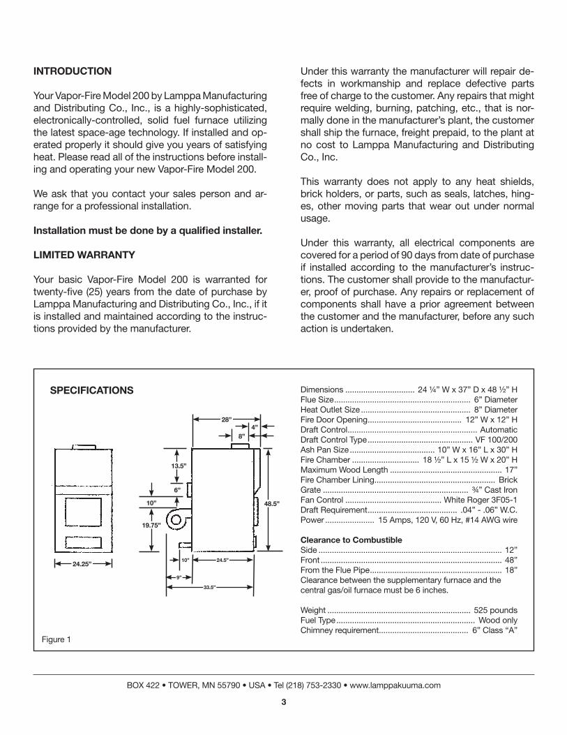
Dimensions ............................... 24 ¼” W x 37” D x 48 ½” HFlue Size ............................................................. 6” DiameterHeat Outlet Size ................................................. 8” DiameterFire Door Opening .......................................... 12” w x 12” hDraft Control .......................................................... AutomaticDraft Control Type ............................................... VF 100/200Ash Pan Size ...................................... 10” W x 16” L x 30” HFire Chamber .............................. 18 ½” L x 15 ½ W x 20” HMaximum Wood Length .................................................. 17”Fire Chamber Lining ...................................................... Brickgrate ................................................................. ¾” Cast IronFan Control ........................................... White Roger 3F05-1Draft Requirement ........................................ .04” - .06” w.C.Power ...................... 15 Amps, 120 V, 60 Hz, #14 AWG wire
Clearance to Combustibleside .................................................................................. 12”Front ................................................................................. 48”From the Flue Pipe ........................................................... 18”Clearance between the supplementary furnace and the central gas/oil furnace must be 6 inches.
Weight ................................................................ 525 poundsFuel Type .............................................................. Wood onlyChimney requirement ........................................ 6” Class “A”
SPeCIFICatIonS
Figure 1
28”
24.25”
9”
24.5”
33.5”
48.5”
6”
13.5”
10”
19.75”
10”
4”8”

BOX 422 • TOWER, MN 55790 • USA • Tel (218) 753-2330 • www.lamppakuuma.com
4
1. Read thoroughly all of the installation and op-eration instructions before attempting instal-lation.
2. If your stove doesn’t have any bricks, install the bricks as shown in Figure 2. (Also see Figure 4, page 5)
3. The unit must be set on a non-combustible surface, such as brick, ceramic tile, stone, or concrete and be at least 1 inch in thickness and 18 inches larger than the dimensions of the base as stated in the specifications, Fig-ure 1. The non-combustible floor protection must extend at least 16 inches in front of the unit.
4. Install the blower assembly to the back of the unit as shown in Figure 3. See Figure 16 for
typical hot air hookup.
5. Use 6 inch stove pipe to connect the smoke outlet in the back of the stove to an aP-ProVeD CLaSS a CHIMney. Install only one connection to one flue. Make sure you use at least three metal screws at each joint connection.
6. Install a barometric draft control field 6” RC/BT as described and illustrated on page 12 and 13, also see Figures 21 and 22.
7. We SuGGeSt tHat a LICenSeD eLeC-trICIan Be HIreD to Do aLL your eLeCtrICaL ConneCtIonS. See wiring diagram, Figures 6 and 24, page 10.
1. Open fire door.
2. Scrape the ashes through the grate.
3. Place a moderate amount of paper and kin-dling on the Front half of the fire chamber floor.
4. Place your logs on top of the paper and kin-dling, making sure that fron face of the logs are kept 1 inch away from the front inside face of the fire chamber, also make sure that the primary air openings as shown in Figure 2 are kept open.
5. Ignite the paper.
6. Open ash pan door approximately 1/4” until draft damper opens.
7. Momentarily hold the fire door open, approx-imately one-half inch, this will assist in ignit-ing the kindling and helps to create the initial draft.
8. Close the fire and ash pan doors tight – the electronic control automatically monitors the fire.
** Open ash pan door momentarily, when draft control is activated – CLoSe aSH Pan Door.
installatiOn instruCtiOns
OperatiOn guiDelinesstarting a Fire in a COlD Fire Chamber withOut any hOt COals

BOX 422 • TOWER, MN 55790 • USA • Tel (218) 753-2330 • www.lamppakuuma.com
5
Figure 16
Figure 3
Figure 2
FIre Door
Front
BaCk
PrIMary aIr oPenInGS
Figure 4
Grate
u-BrICkretaIner
tyPICaL Hot aIr Hook uP
InStaLL GaSket ProVIDeD
InStaLL FILter Box
FIrSt
24.5”
24.25”6”
49”

CHIMney InForMatIon
The chimney is one of the most important yet most neglected and misunderstood portions of any Sol-id Fuel Burning installation. THE FURNACE SHALL nOt be COnneCteD tO the Chimney with Other heating DeViCes.
There are two types of Class “A” chimneys:1. Masonry with tile liner suitable for venting resi-
dential or building heating appliances. (See NFPA 211.)
2. Class “A” Chimney, listed or certified by a na-tionally recognized testing agency as suitable for venting residential or building heating applianc-es. If your masonry chimney has not been used for some time, have it inspected by a qualified person (building inspector, fire department per-
sonnel, etc.) If a listed or certified manufactured chimney is to be used, make certain it is installed in accordance with the manufacturer’s instruc-tions and all local and state codes. See Figure 17, Manufactured Chimney Installation and Figure 18 of Masonry Chimney (note roof clearance) in ac-cordance with NFPA 211.
CoMMon CHIMney ProBLeMS
In order to have a proper operating Solid Fuel Heat System, the chimney must be capable of providing the draft required.
In the Vapor-Fire Model 200 Furnace, the require draft is .04 to .06 water column (W.C.). This can be measured using a draft gauge.
If the chimney cannot supply this constant draft, the unit will not operate properly.
In all furnace installations using Vapor-Fire Model 200 add-on units, a barometric draft regulator must be used and properly adjusted for proper draft provided – set to .06 W.C. by sliding wt. to #6 vertical.
Figure 17 Figure 18
BOX 422 • TOWER, MN 55790 • USA • Tel (218) 753-2330 • www.lamppakuuma.com
6
CautIon
tHe CHIMney MuSt Be a CLaSS “a” CHIMney In GooD oPeratInG ConDItIon. Do not ConneCt tHIS unIt to a CHIMney FLue SerVICInG anotHer aPPLIanCe.
18”
2’
LeSS tHan 18”
More tHan 18”
rIDGe 2” MInIMuM
2” MInIMuM
2” MInIMuM
CLaSS a CHIMney3’ MInIMuM
CLaSS aF CHIMney3’ MInIMuM
MInIMuM HeIGHt reQuIreD aBoVe rooF SurFaCe WItHIn 16” HorIZontaLLy
rIDGe

REASONS for insufficient draft readings:
1. Leaky Chimney – Air leaking in around a loose fitting clean-out door, flue pipes not tight at the joints, improper plug openings, or defective ma-sonry.
2. Chimney Improper Height – Chimney does not extend through the roof to a sufficient height to promote sufficient draft or causes a down draft-ing condition to take place. See NFPA 211.
3. Obstructions in the chimney – Check prior to us-ing holding a mirror in chimney cleanout door. This will give an inside view of the chimney.
4. Trees or other topographical barriers – Impending the chimneys operation or causing a down draft condition to exist. This can also be caused by ad-jacent building or the roof of the same structure where the chimney is not high enough (Figure 19).
5. Chimney Size – Chimney is not properly sized to adequately fit the appliance. It is either too small or too large. Minimum chimney height – 14 foot. Minimum Diameter – 6 inches.
6. Chimney Offsets – Chimneys with offsets should not be used. They cause an obstruction to draft as well as a place for debris to collect.
7. Elbow Restrictions – The flue pipe is connected to the chimney with too many elbows reducing the draft chimney can provide.
8. Multiple Venting – When more than one (1) devise vents into the same chimney flue.
When smoke rises into the chimney, it will rise in a spiraling path.
The most important thing to remember about chim-neys is their need for maintenance and cleaning. If chimneys are not cleaned on a regular basis, it ef-fects the draft, as well as make an attributing cause to a chimney fire.
The draft can be improved by using a chimney cone (figure 20) or by extending the height of the chimney and reducing the flue area. A cone or chimney exten-sion can be made by a local sheet metal shop.
A properly operating chimney will tend to reduce the amount of creosote that is left deposited.
Instructions for installation, draft measurement, ad-justment of the barometric draft regulator.
BOX 422 • TOWER, MN 55790 • USA • Tel (218) 753-2330 • www.lamppakuuma.com
7
Figure 20
nOte: the Chimney On the hOuse illustrateD is tOO lOw. it shOulD be raiseD tO COmpensate FOr DraFts.
GaLVanIZeD CHIMney Cone
Figure 19
CautIon
neVer ConneCt to an outSIDe CHIMney unLeSS It IS SuFFICIentLy InSuLateD to reDuCe tHe aMount oF ConDenSatIon to a LeVeL tHat WILL not IntereFere WItH tHe exHauSt oF tHe FLue GaSeS.
45 DeGree ConneCtIon
StoVeCHIMney
DaMPer
BOX 422 • TOWER, MN 55790 • USA • Tel (218) 753-2330 • www.lamppakuuma.com
8
Figure 22
Figure 23
Figure 21
CautIon
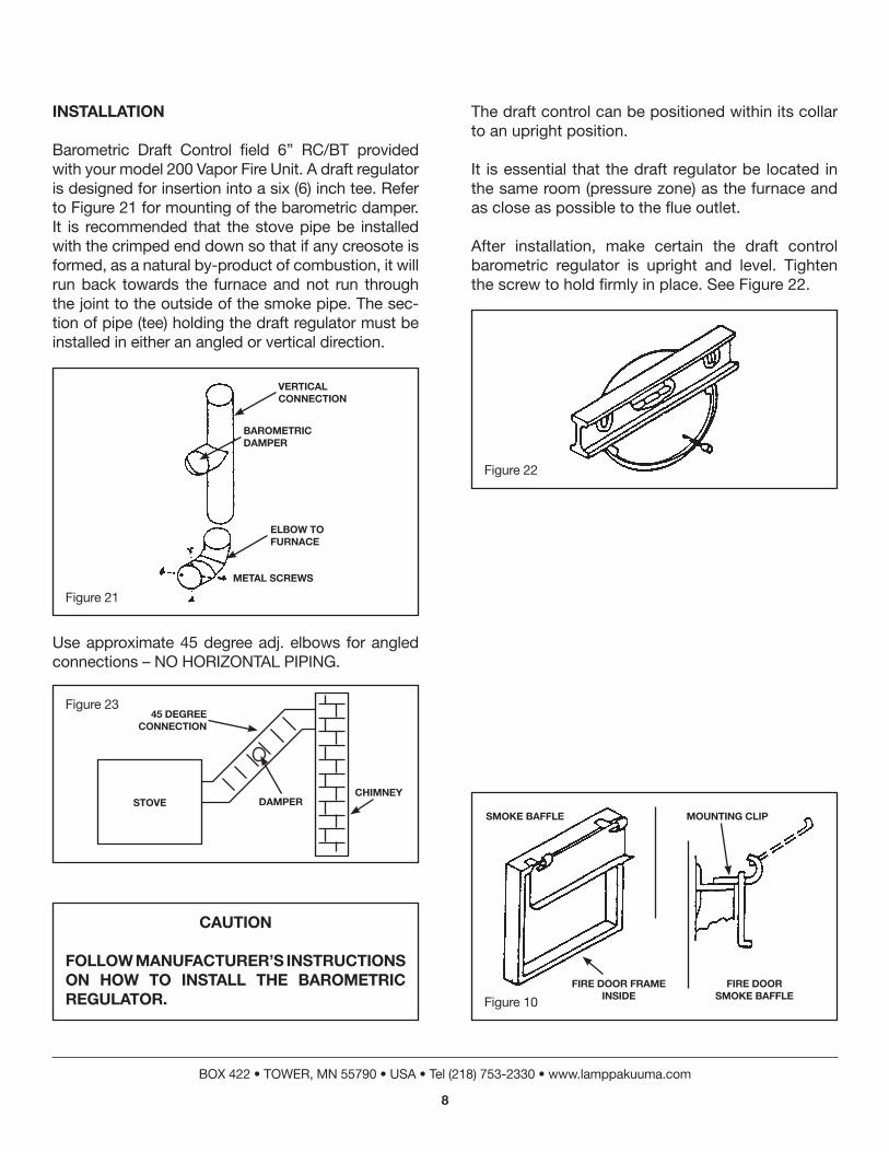
FoLLoW ManuFaCturer’S InStruCtIonS on HoW to InStaLL tHe BaroMetrIC reGuLator.
Use approximate 45 degree adj. elbows for angled connections – NO HORIZONTAL PIPING.
InStaLLatIon
Barometric Draft Control field 6” RC/BT provided with your model 200 Vapor Fire Unit. A draft regulator is designed for insertion into a six (6) inch tee. Refer to Figure 21 for mounting of the barometric damper. It is recommended that the stove pipe be installed with the crimped end down so that if any creosote is formed, as a natural by-product of combustion, it will run back towards the furnace and not run through the joint to the outside of the smoke pipe. The sec-tion of pipe (tee) holding the draft regulator must be installed in either an angled or vertical direction.
The draft control can be positioned within its collar to an upright position.
It is essential that the draft regulator be located in the same room (pressure zone) as the furnace and as close as possible to the flue outlet.
After installation, make certain the draft control barometric regulator is upright and level. Tighten the screw to hold firmly in place. See Figure 22.
BaroMetrIC DaMPer
VertICaL ConneCtIon
eLBoW to FurnaCe
MetaL SCreWS
Figure 10
SMoke BaFFLe MountInG CLIP
FIre Door FraMe InSIDe
FIre Door SMoke BaFFLe

To tighten the door on the handle side – loosen the two set screws, lower handle behind latch, push door in tightly and tighten set screws. (Figure 9)
When adjusting doors, loosen the two screws (Fig-ures 13 & 14) and push door in until there is a slight bind. As you close the door, making sure it is not too tight, tighten the screws.
Figure 9
Figure 13
Figure 14
Door HanDLe
Door LatCH
aDjuSt SCreW
HInGe PInHInGe PIeCe
Door FraMe
FIre Door
PIVot SCreW
aDjuStMent SCreWS
SIDe PIeCe LatCH
BOX 422 • TOWER, MN 55790 • USA • Tel (218) 753-2330 • www.lamppakuuma.com
9
Figure 25
Figure 7
aDjuStaBLe HInGe For tHe DoorS
HInGe
BoLtS
Door
GaSket
SteP Motor ControL
PLuGS Into CIrCuIt BoarD VIa FLat CaBLe
HeLPFuL HIntS
1. Use only dry, seasoned wood that has been cut and split and placed under cover to dry for 6 to 9 months. (25-30% moisture content). Hardwood should be one year drying time to be seasoned.
2. Use 16” wood lengths. (Fire chamber is 18 ½”)
3. Never burn less than two (3-piece minimum, tri-angle shaped) rows of wood, regardless of their size. The reason for this that each log gives off its heat to the adjoining log to sustain continuous combustion.
4. Do not start a fire in a cold fire chamber with ex-cessive amounts of paper and kindling, because the chimney is cold and lacks sufficient draft causing the “chugging” effect that could produce some puffing of smoke through your pipe joints.
5. Keep the front one-half (9”) of the fire chamber free of grey ashes.
6. Always rake the hot coals forward from the back, but leaving a space of 1 to 2 inches between the front inside face and the hot coals.
7. Always burn down the coals if they are exces-sive. When the coals have been raked forward, the back half of the fire chamber floor should be free of any hot coals. If the logs are added when there are hot coals in the back, the logs will ignite and burn from the back to the front, just opposite from what it should be.
8. Whenever wood lengths are added to the fire chamber, when there are some hot coals, make sure that the front of the logs are in contact with the hot coals so that the logs ignite.
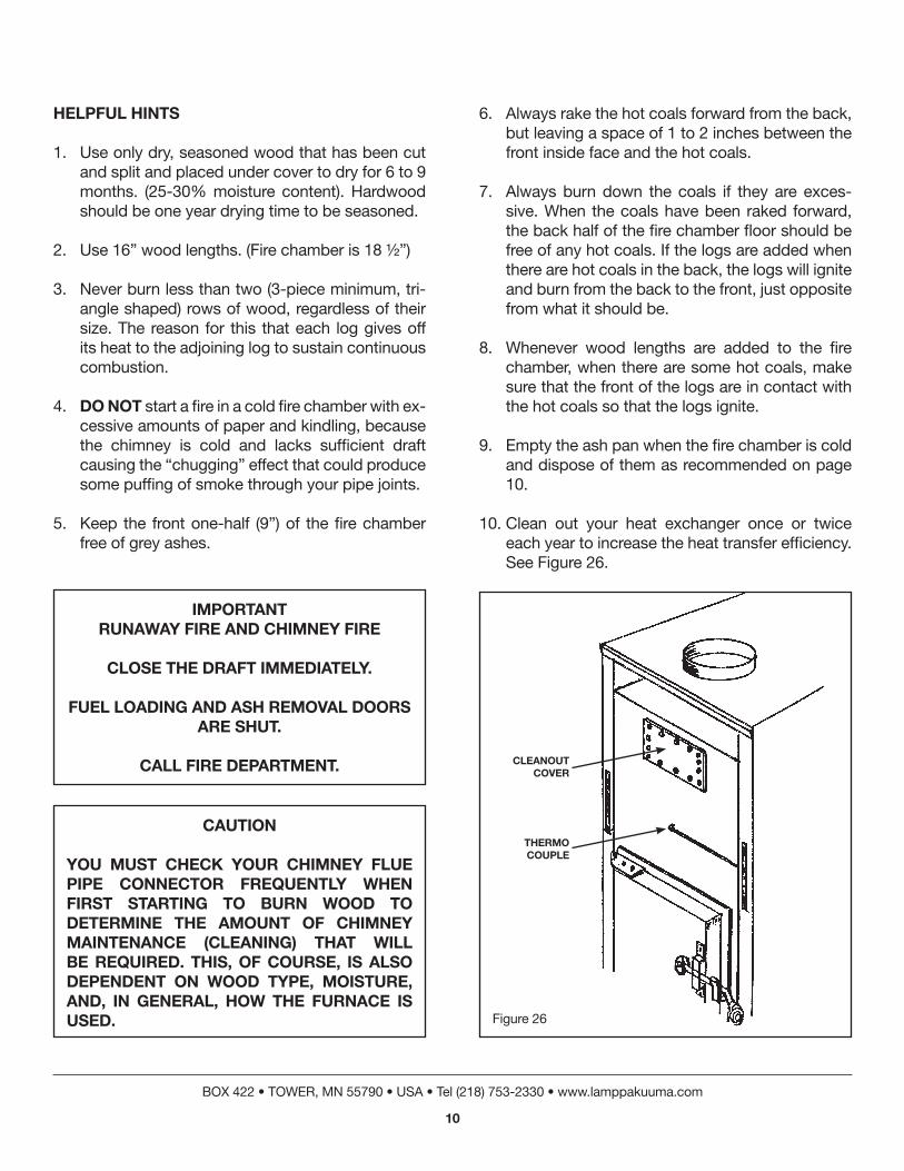
9. Empty the ash pan when the fire chamber is cold and dispose of them as recommended on page 10.
10. Clean out your heat exchanger once or twice each year to increase the heat transfer efficiency. See Figure 26.
BOX 422 • TOWER, MN 55790 • USA • Tel (218) 753-2330 • www.lamppakuuma.com
10
IMPortantrunaWay FIre anD CHIMney FIre
CLoSe tHe DraFt IMMeDIateLy.
FueL LoaDInG anD aSH reMoVaL DoorS are SHut.
CaLL FIre DePartMent.
CautIon
you MuSt CHeCk your CHIMney FLue PIPe ConneCtor FreQuentLy WHen FIrSt StartInG to Burn WooD to DeterMIne tHe aMount oF CHIMney MaIntenanCe (CLeanInG) tHat WILL Be reQuIreD. tHIS, oF CourSe, IS aLSo DePenDent on WooD tyPe, MoISture, anD, In GeneraL, HoW tHe FurnaCe IS uSeD. Figure 26
CLeanout CoVer
tHerMo CouPLe
norMaL autoMatIC oPeratIon
When power is turned on the furnace is cold, the draft will be closed. As the temperature in the fire box rises to approximately 100-120 degrees F., the auto-matic draft opens allowing combustion air to enter the fire chamber. As the temperature in the fire cham-ber rises, the automatic draft will begin its throttling process until it is completely closed allowing maxi-mum furnace idling. (When it reaches your desired setting.)
As the outer heat jacket temperature rises past 105 degrees F., the fan starts automatically and contin-ues to operate until the fire burns down and the heat jacket cools to approximately 90 degrees F.
autoMatIC DraFt ControL
Indicating lights are furnished on the electric control to provide the following:
A. Thermocouple indicator light is on when there is an open circuit in the thermocouple. The auto-matic draft will remain closed. Replace the ther-mocouple.
B. Low temperature indicator light is on when the fire chamber is below 70 – 100 degrees F. and the automatic draft is closed.
C. The draft indicator lights are on indicating that draft stages are open.
D. High temperature indicating light is on when there is a high temperature in the fire chamber. Tighten door adjustment to eliminate door leaks. See sticker on the Electronic Draft Controller.
BOX 422 • TOWER, MN 55790 • USA • Tel (218) 753-2330 • www.lamppakuuma.com
11
WarnInG
LaCk oF enouGH aIr For ProPer CoMBuStIon
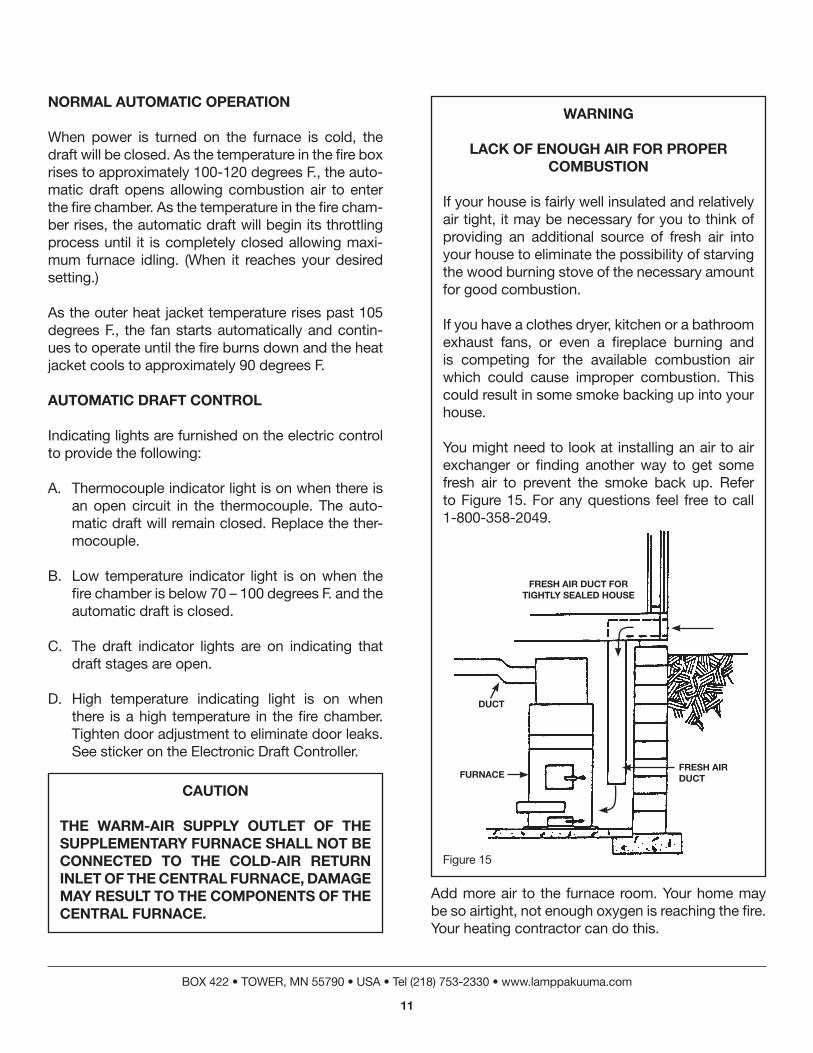
If your house is fairly well insulated and relatively air tight, it may be necessary for you to think of providing an additional source of fresh air into your house to eliminate the possibility of starving the wood burning stove of the necessary amount for good combustion.
If you have a clothes dryer, kitchen or a bathroom exhaust fans, or even a fireplace burning and is competing for the available combustion air which could cause improper combustion. This could result in some smoke backing up into your house.
You might need to look at installing an air to air exchanger or finding another way to get some fresh air to prevent the smoke back up. Refer to Figure 15. For any questions feel free to call 1-800-358-2049.
Figure 15
FreSH aIr DuCt For tIGHtLy SeaLeD HouSe
DuCt
FurnaCeFreSH aIr DuCt
Add more air to the furnace room. Your home may be so airtight, not enough oxygen is reaching the fire. Your heating contractor can do this.
CautIon
tHe WarM-aIr SuPPLy outLet oF tHe SuPPLeMentary FurnaCe SHaLL not Be ConneCteD to tHe CoLD-aIr return InLet oF tHe CentraL FurnaCe, DaMaGe May reSuLt to tHe CoMPonentS oF tHe CentraL FurnaCe.

BOX 422 • TOWER, MN 55790 • USA • Tel (218) 753-2330 • www.lamppakuuma.com
12
reLoaDInG on Hot CoaLS
1. Open fire door.
*** Never load any logs when there is still some un-burnt wood in the fire chamber, also refrain from opening the fire door while the logs are burning.
2. Scrape the ashes through the grates as shown in Figure 8 & 11.
3. Pull the hot coals from the back of the fire cham-ber forward, but never closer than one inch from the front inside face.
*** If the accumulation of coals is thicker than 4-5 inches (half way up the first row of bricks) pull them forward, again leaving a space of one inch between the coals and the front inside face. Close the fire door and allow the coals to burn down to the recommended level. Don’t oPen tHe aSH Pan Door to aCCoMPLISH tHIS.
4. Load the logs so that the face of the logs are 1 to 2 inches away from the front inside face, see Figure 12.
5. Close the door – the electronic control automati-cally monitors the fire.
6. Periodically inspect the primary air openings to make sure that they are free and clear of any ash-es. The long narrow slit between the two square holes MuSt be kept clean. (see Figure 2)
DISPoSaL oF aSHeS
Ashes should be placed in metal container with a tight fitting lid. The closed container of ashes should be place on a non-combustible floor or on the ground, well away from all combustible materials, pending fi-nal disposal. If the ashes are disposed of by burial in the soil or otherwise locally dispersed, they should be retained in a closed container until all cinders have thoroughly cooled.
CreoSote-ForMatIon anD neeD For reMoVaL
When wood is burned slowly it produces tar and other organic vapors, which combine with expelled moisture to form creosote. The creosote vapors con-dense in the relatively cool chimney flue of a slow burning fire. As a result, creosote residue accumu-lates on the flue lining. When ignited, this creosote makes an extremely hot fire.
The chimney connector and chimney should be in-spected at least twice monthly during the heating season to determine if a creosote buildup has oc-curred.
If creosote has accumulated, it should be removed to reduce the risk of a chimney fire.
Figure 12
tHe LoGS Burn FroM tHe Front to tHe BaCk.
1” - 2” FroM tHe
Front
Hot CoaLS
aSHPan

BOX 422 • TOWER, MN 55790 • USA • Tel (218) 753-2330 • www.lamppakuuma.com
13
Figure 8
IMPortant
keeP aSH DraWer eMPty.
IF aSHeS are PerMItteD to BuILD uP aBoVe tHe Grate, tHe GrateS CouLD WarP anD eVentuaLLy Burn out.
DanGer
neVer Burn MaterIaLS otHer tHan WooD LoGS, PreFeraBLy SPLIt anD DrIeD.
a CHIMney FIre or Heat exCHanGer FaILure CouLD reSuLt. tHIS InCLuDeS LarGe aMountS oF CorruGateD BoxeS, WooDSHaVInGS, PaPer SCraPS, DrIeD CHrIStMaS treeS, CoaL, GarBaGe, tIreS or otHer BurnaBLe ProDuCtS.
IMPortant
DurInG norMaL oPeratIon, FIrInG Door anD aSH Door MuSt Be kePt tIGHtLy CLoSeD. aIr LeakaGe WILL CauSe LoSS oF eFFICIenCy reSuLtInG In HIGHer HeatInG CoStS. IF Door GaSketS BeCoMe Worn, rePLaCe WItH 5/8” anD 1/2” CeraMIC roPe aVaILaBLe FroM LoCaL SourCeS.
DoS anD Dont’S oF oPeratIon
Wood Firing the Unit
Rake hot coals to the FRONT as shown, DO NOT BLOCK PRIMARY air Openings.
Keep coals approximately 1” from front air inlets.
Hot CoaLS
BaCk
aSHeS
Hot CoaLS
aSH Pan
rake
aIr
PrI
Mary
Figure 11

BOX 422 • TOWER, MN 55790 • USA • Tel (218) 753-2330 • www.lamppakuuma.com
14
InStruCtIonS DurInG PoWer FaILure
DO nOt burn this unit with the Fuel Or ash DOOrs Open During pOwer Failure.
DO NOT BLOCK THE COMBUSTION AIR DAMPER SYSTEM OPEN DURING POWER FAILURE, the unit will create sufficient heat on low idle. Excessive duct temperatures may cause a house fire.
Removed Air Filter manually open 8” back draft damper.
NEVER BLOCK THE FLOW OF HEATED AIR FROM the unit intO the rOOm.
Remove front lift off hood for more gravity heat flow.
For further information on using your heater safely, obtain a copy of the National Fire Protection Asso-ciation publication “Using Coal and Wood Stoves Safely,” NFPA No. HS-10-1978. The address of the NFPA is 470 Atlantic Avenue, Boston, Massachu-setts 02210.
Figure 6 Figure 24
DanGerrISk oF FIre or exPLoSIon
Do not Burn GarBaGe, GaSoLIne, DraIn or enGIne oIL, keroSene, FueL oIL, or otHer FLaMMaBLe LIQuIDS.
Do not uSe CHeMICaLS or FLuID to Start FIre.
Heat SenSor(90° - 130°F)
ConDuIt
utILIty Box
CoVerS
tCHeat
SenSor
Fan ControL
Motor
reD
reD
tt
tC
tC
LoW
yeLLoW
VoLtaGe
24 VtranS
Bn BLk
115 VaC 15 aMP
BLkWt
Gn
eLeCtronICDraFtControL

BOX 422 • TOWER, MN 55790 • USA • Tel (218) 753-2330 • www.lamppakuuma.com
15
BeSt WooD For BurnInG
Generally wood should be cut at least a year in ad-vance and properly split at that time.
This wood should also be stored out of the weather, if possible. If the wood is to remain outside, be sure to cover the top of the wood piles with sheets of metal, etc. This wood should be brought inside and stored there for at least two (2) weeks before it is fired to obtain top performance.
Soft woods burn at a faster rate per cord than do hard woods, and have less BTUs per cord.
Know what types of wood to burn. Wood is safe, clean and economical fuel. Freshly felled wood is not suitable fuel due to the moisture content of the wood. Well-seasoned wood is best for the proper produc-tion of heat. The following table will give you some relative values of the heating content of some of (the more readily available wood).
EquivalentType Weight BTU’s Per Value #2 Cord Cord Air Fuel Oil Dried Wood Gallons––––––––––––––––––––––––––––––––––––––––––––––White Pine 1800# 17,000,000 120Aspen 1900 17,500,000 125Spruce 2100 18,000,000 130Ash 2900 22,500,000 160Tamarack 2500 24,000,000 170Soft Maple 2500 24,000,000 170Elm 2750 24,500,000 175Yellow Birch 3000 26,000,000 185Red Oak 3250 27,000,000 195White Oak 3750 27,700,000 200Hard Maple 3000 29,000,000 200Hickory 3500 30,500,000 215
uSeFuL FaCtS
No. 2 Fuel Oil – 140,000 BTU/gallonNatural Gas – 100,000 BTU/thermPropane Gas – 93,300 BTU/gallonButane Gas – 100,671 BTU/gallonElectricity – 3,413 BTU/kilowatt – hour
WooD BurnInG FaCtS
BE AWARE OF CREOSOTE “BUILD-UP” WHEN burning wOOD!
Wood burning equipment will give you trouble with creosote deposits under certain conditions, unless you are aware of these conditions and avoid them.
Creosote is a tarry liquid or solid resulting from the distilling of wood during the combustion process. It consists of a number of elements which condense and bake layer upon layer in the chimney flue.
Highly combustible in its solid and semi-liquid state, creosote is present in the gases given off by burning wood. Creosote may build up a considerable thick-ness on the interior surface of the chimney and flue pipes, considerably reducing their cross-sectional area.
Creosote condenses from the flue gases when the stack temperature drops below 250 degrees F. The amount of creosote deposited in the pipe and chim-ney is dependent on the amount of moisture in the flue gases, the temperature of the stack, and how completely the combustible elements in the flue gases have been burned in the combustion process. Most problems with creosote are due to poor chim-neys with low draft and cold walls and to a low rate of burning when heat is needed during the spring and fall months.
Moisture in the flue gases may be controlled by us-ing the driest wood possible, mixing small pieces with a very full load, and never using only large wood during mild weather when combustion is rela-tively slow.
WarnInG
SerIouS FIre May reSuLt IF a SuFFICIent CreoSote “BuILD-uP” IS PerMItteD oVer an extenDeD PerIoD oF tIMe.

BOX 422 • TOWER, MN 55790 • USA • Tel (218) 753-2330 • www.lamppakuuma.com
16
HoW to ConneCt tHe 8” Hot aIr outLet to your exIStInG FurnaCe
1. Keep in mind that your add-on kuuMa is de-signed to blow it’s hot air into your existing oil or gas furnace’s bonnet, which in turn, with it’s larger blower then blows and distributes the hot air throughout your house. The 465 CFM KUU-MA blower and your furnace blower must be controlled in such a way as to deliver the hot air throughout your home.
2. Your KUUMA add-on should be located as close to your existing furnace as allowed by u.L. clear-ances. Measure the required length of pipe and then install an 8” back-draft damper in this pipe so it is located somewhere between the add-on and your furnace, then connect the 8” heat outlet pipe from the KUUMA to somewhere close to the center of your bonnet on the side closest to the add-on. You should avoid having a long distance between your KUUMA and your furnace, be-cause you will lose a lot of heat the further apart they are.
3. The function of the back-draft damper is that it acts like a check valve, if the add-on isn’t blow-ing the damper is closed and stops the regular furnace from blowing it’s hot air into the add-on. (If the oil or gas furnace continually pumps hot air into the add-on it’s blower will become over-heated and damaged – which you don’t want.
4. You should install another limit control switch in your bonnet at approximately the same height as to where the KUUMA duct enters the bonnet – this is necessary so the control can accurately activate the larger blower in your furnace. Ahead of this limit switch you should install a manual on and off switch so you can deactivate the blower at any time you find it necessary. For example: in mild weather you may only need the heat from the KUUMA add-on (See Below)
5. Approximate settings for the limit switch should be 130 degrees on and 100 degrees off. If these
settings are incorrect you may have the blower cycling on and off too quickly. You may need to experiment to suit your needs.
Many of the suggestions are only estimates, for ev-ery installation will vary. We strongly insist that above anything else “safety issues come first”.
We strongly recommend that you have a licensed electrician do any of your electrical work.
InStruCtIonS on ConneCtInG tHe 6” StoVe PIPe
1. Use 24 ga. stove pipe and adjustable elbows.
2. Angle your stove pipes upward towards the chim-ney smoke exit hole.
3. Install barometric damper provided.
4. avoid using 90 degree pipe bends unless it’s one 90 degree and then straight up. Otherwise try to use 45 degree elbows (approximate) to maximize the draft.
5. Use sheet metal screw to attach all the pipes with at least three screws evenly spaced around the pipe and any joint.
6. Check and inspect pipes periodically for corro-sion or any other defects.
SaFety SHouLD aLWayS Be nuMBer one.

VaPor FIre 200 aDD-on FILter Box InStaLLatIon InStruCtIonS
1. Install the motorized air intake control box onto the back air inlet throat.
2. To remove the bottom electrical box unscrew the lock nut inside the junction box leaving the ½ inch conduit in place. Keep in mind that after the installation of the filter box, the electrical box and nut will go back to their original location.
3. Scribe a line on the back of the hood 26” up from the floor.
4. Hold the filter box against the back of the stove and at the same time run the 1/2” conduit through the 7/8” hole located on the right hand corner on top of the filter box.
5. Align the top of the filter box to the scribed line which you had previously scribed on the back of the stove, making sure that the filter box is aligned equal distances from the sides and is centered equally from side to side.
6. Through the pre-punched holes in the filter box, scribe through these holes onto the back of the stove hood. Drill these holes in the back of the stove so the filter box can be screwed securely to the hood.
Make Sure tHe HoLeS DrILLeD are tHe CorreCt SIZe So tHat tHe SCreWS WILL SeCureLy HoLD tHe Box.
7. Re-install securely the bottom electrical box in the same location which will not be in the up-per right and corner InSIDe the filter box.
8. Install the blower gasket and blower to the back of the stove using the bolts and nuts provided, located in the back of the stove.
9. Install the incoming 120V power through the pre-punched 7/8” hole on the filter box.
10. Wire the stove according to UL label as shown in the owner’s manual provided.
11. Install the 14” x 20” filter that is provided.
CHeCk to Make Sure eVerytHInG IS In-StaLLeD CorreCtLy BeFore LIGHtInG tHe StoVe.
BOX 422 • TOWER, MN 55790 • USA • Tel (218) 753-2330 • www.lamppakuuma.com
17
WarnInGrISk oF FIre
Do not oPerate WItH FLue DraFt exCeeDInG .06 InCHeS Water CoLuMn.
Do not oPerate WItH FueL LoaDInG or aSH reMoVaL DoorS oPen.
Do not Store FueL or otHer CoMBuStIBLe MaterIaL WItHIn MarkeD InStaLLatIon CLearanCeS.
InSPeCt anD CLean FLueS anD CHIMney reGuLarLy.
CautIon
SurFaCeS are Hot
keeP CHILDren aWay
Do not touCH DurInG oPeratIon

HoW tHe VaPor FIre eLeCtronIC DraFt ControL WorkS
reaD OVer the FOllOwing explanatiOns Very CareFully
1. When you first turn on the power – the 24 volt electronic control is energized, the controls high temperature siren sounds for only a short time, then after this, the control will automatically go to the low temperature setting which is when only the GREEN LIGHT is on.
2. When first starting a fire, you may open the ash pan door for a very short while until the control senses the heat which is being generated by the fire. Once the control senses the heat it will au-tomatically open the draft shutter. (ALL THREE LIGHTS WILL THEN BE ON). Allow the ash pan door to remain open for a short period of time to assure that the wood has properly ignited. NOW ClOse the ash pan DOOr anD the eleC-TRONIC CONTROL WILL TAKE OVER AND IT will COntrOl the DraFt as neeDeD tO BURN THE WOOD, MAKE SURE THE ASH pan DOOr remains ClOseD anD that the LATCH IS HOOKED THROUGHOUT THE EN-tire burn.
*** neVer eVer Burn tHe StoVe WItH tHe aSH Pan Door oPen otHer tHen DurInG tHe FIrSt FeW MInuteS WHen StartInG tHe FIre.
3. The electronic control has four different stages and the lights on the control indicate how much air is entering the fire chamber, for example as follows:
A. At start up, all three lights are on and also again at the end of the burn cycle, this indi-cates that the shutter is wide open.
B. As the fire gradually intensifies, only two lights are on which means that the control has automatically decreased the amount of air going into the fire chamber, now the shutter is partially closed.
C. As the temperature in the fire chamber con-tinues to rise, the control automatically closes so that only One light is on which means that the shutter is almost close.
D. When the temperature in the fire chamber has reached it’s optimum level, there will be nO lights On. Now the shutter is completely closed, the stove is now what we call on the pilot burn and will continue like this until the fire cham-ber cools down and then the control again takes over and will adjust the shutter opening based on the fire chamber temperature.
4. The LOW TO HIGH TEMPERATURE KNOB is used to adjust the total heat output of the vapor fire furnace, depending on what the temperature is outside.
Hot
CoLDHot
CoLD
StoP
For PoWer outaGeoPen ManuaLLy
8” BaCk DaMPer
oIL
or
GaS
or
eLeCtrIC
VF200
This is just the basic idea to tie the two systems together. The cold air side back flow flap may or may not be needed.
BOX 422 • TOWER, MN 55790 • USA • Tel (218) 753-2330 • www.lamppakuuma.com
18
Hot
465 CFM
CoLD aIr FroM
uPStaIrS
BaCk FLoW FLaP
StoP

trouBLe SHootInG
iF yOu haVe trOuble starting the Fire CHECK THE FOLLOWING:
A. Chimney draft should read between .04” to .06” water column.
B. Smoke pipes are clean.
C. Chimney is clean.
D. More than one unit connected to one chimney.
E. Chimney may be too low. Increase its height.
F. Chimney may have cracks and excessive leakage.
G. Cleanout door is open.
H. The primary opening on your KUUMA is filled with ashes.
I. House is too air tight. To correct this see Figure 15.
J. Wood is too wet.
K. Avoid 90 degree elbows and horizontal piping.
L. Chimney cap must not have a mesh on it.
M. Automatic draft not 24V working – check for AL
IF BLOWER MAKES EXCESSIVE NOISE:
A. Blower fans are filled with dust.
B. Motor bearings are bad.
C. Blower is loose on its mounting bracket.
BOX 422 • TOWER, MN 55790 • USA • Tel (218) 753-2330 • www.lamppakuuma.com
19

BOX 422 • TOWER, MN 55790 • USA • Tel (218) 753-2330 • www.lamppakuuma.com
20
InStaLLatIon
1. Mount the unit in the position most desirable to your needs.
2. Connect the two leads to the appropriate power source. Refer to blower name plate.
CautIon: a ground wire must run from the blower motor housing to a suitable electrical ground such as a properly grounded metallic raceway or ground wire system.
3. Wiring Diagram for Model 4C565A 2-speed blow-er only.
NOTE: IF ONLY ONE SPEED IS USED, ISOLATE THE REMAIN-ing leaD with eleCtriCians tape Or plastiC COnneC-tOr.
MaIntenanCe
WarnInG: aLWayS DISConneCt PoWer SuPPLy Be-Fore SerVICInG tHe BLoWer or WorkInG WItH tHe unIt For any reaSon. tHIS IS eSPeCIaLLy IMPortant WItH unItS eQuIPPeD WItH autoMatIC-reSet tHer-MaL ProteCtIon. unIt May aCtIVate WItHout Warn-InG!
LuBrICatIon
The motor should be re-lubricated every 6 months with 10 or 20 drops of SAE 10W or 20W non-deter-gent oil (ML-type) or with electric motor oil.
NO LUBRICATION FOR 1TDR9
GeneraL
Should further servicing of the unit be necessary, re-fer to the “exploded” view illustration as an aid in dis-assembly and assembly procedures.
limiteD warranty
Dayton blowers, Models 4C004A, 4C005, 4C008B, 4C012A, 4C013A, 4C264A, 4C446, 4C447, 4C448A, and 4C565A, are warranted by Dayton Electric Mfg. Co. (Dayton) to the original user against defects in workmanship or materials under normal use (rental use excluded), or one year after date of purchase. Any part which is determined to be defective in material or workmanship and returned to an authorized service location, as Dayton designates, shipping costs prepaid, will be repaired or replaced at Dayton’s option. For warranty claim procedures, see “Prompt Disposition” below. This warranty give purchaser’s specific legal rights and purchasers may also have other rights which vary from state to state.
WARRANTY DISCLAIMER. Dayton has made a diligent effort to illustrate and describe the products in this literature accurately, however, such illustrations and descriptions are for the sole purpose of identification, and do not express or imply a warranty that the products are merchantable, or fit for a particular purpose, or that the products will necessarily conform to the illustrations or descriptions.
Except as provided below, no warranty or admission of fact, expressed or implied, other than as stated in “LIMITED WARRANTY” above is made or authorized by Dayton, and Dayton’s liability in all events is limited to the purchase price paid.
Certain aspects of disclaimers are not applicable to consumer products’ e.g., (a) some states do not allow the exclusion or limitation of incidental or consequential damages, so the above limitation or exclusion may not apply to you; (b) also, some states do not allow limitations on how long an implied warranty lasts, consequently the above limitation may not apply to you, and (c) by law, during the period of this Limited Warranty, any implied warranties of merchantability or fitness for a particular purpose applicable to consumer products purchased by consumers, may not be excluded or other-wise disclaimed.
PROMPT DISPOSITION. Dayton will make a good faith effort for prompt correction or other adjustment with respect to any product which proves to be defective within warranty. For any product believed to be defective within warranty, first write or call dealer from whom product was purchased. Dealer will give additional directions. If unable to resolve satisfactorily, write to Dayton at address below, giving dealer’s name, address, date and number of dealer’s invoice, and describing the nature of the defect. If product was damaged in transit to you, file claim with carrier.
DAYTON ELECTRIC MFG. CO., 5959 W. HOWARD ST., CHICAGO, ILLINOIS 60648
FORM 5S252004040
MODELS 4C004A, 4C005, 4C006B, 4C012A, 4C013A, 4C284A, 4C446, 4C447, 4C448A, 4C565A, AND ITDR9
BLaCk (HIGH SPeeD)
WHIte (CoMMon)
reD (LoW SPeeD)
Green (GrounD)
Motor
trouBLe SHootInG CHart
symptOm pOssible Cause(s) COrreCtiVe aCtiOn
Excessive Noise. 1. Blower wheel contacting housing. 1. Realign or replace. 2. Foreign material inside housing. 2. Clean. 3. Leak in duct work. 3. Repair. 4. Loose duct work. 4. Secure properly
Insufficient air flow. 1. Leaks in duct work. 1. Repair 2. Dampers and/or registers closed. 2. Open. 3. Obstruction in system. 3. Remove 4. Clogged Filters. 4. Clean or replace.
Unite fails to operate. 1. Blown fuse or open circuit breaker. 1. Replace fuse or reset circuit breaker. 2. Defective motor. 2. Replace. 3. Automatic-reset thermal protector “tripped”. 3. Check for high (or low voltage input or ambi-
ent temperatures in excess of 40° C (104° F). 4. Motor improperly wired. 4. Re-wire.

BOX 422 • TOWER, MN 55790 • USA • Tel (218) 753-2330 • www.lamppakuuma.com
21
FORM 5S2520 04040
MODEL 1TDR9
re
PLa
Ce
Me
nt
Pa
rt
S L
ISt
Par
t Num
bers
For
Mod
el
Ref
. No.
D
escr
iptio
n 4C
004A
4C
005
4C00
6B
4C01
2A
4C01
3A
4C26
4A
4C44
6 4C
447
4C44
8A
4C56
5A
1
Hou
sing
88
53-4
078
8853
-405
3 88
53-4
092
8853
-408
2 88
53-4
009
8853
-420
6 88
53-4
053
8853
-400
9 88
53-4
206
8853
-420
6
2
Inle
t rin
g 87
93-4
006
8793
-400
8 87
93-0
801
8793
-400
9 87
93-4
049
8793
-404
9 87
93-4
008
8793
-404
9 87
93-4
049
8793
-404
9
3
Blo
wer
whe
el
0905
-005
8 09
21-0
008
0914
-000
3 09
05-0
393
8710
-000
3 09
21-0
008
0921
-000
8 87
10-0
003
8710
-002
8 87
10-0
028
4
Gas
ket
0912
-016
7 09
12-0
167
0912
-016
7 09
20-0
069
0912
-016
7 —
09
12-0
167
0912
-016
7 —
—
5
Out
let b
ox c
over
85
91-6
482
8591
-648
2 85
91-6
482
- 85
91-6
482
—
8591
-648
2 85
91-6
482
—
—
6
Was
her*
#8
#8
#8
#8
#8
#8
#8
#8
#8
#8
7
Nut
* #8
-32
#8-3
2 #8
-32
#8-3
2 #8
-32
#8-3
2 #8
-32
#8-3
2 #8
-32
#8-3
2
8
Gro
mm
et
0912
-016
8 09
12-0
168
0912
-016
8 —
09
12-0
168
—
0912
-016
8 09
12-0
168
—
—
9
Scr
ew*
#8-1
/4
#8-1
/4
#8-1
/4
#8-1
/4
#8-1
/4
#8-1
/4
#8-1
/4
#8-1
/4
#8-1
/4
#8-1
/4
10
M
otor
3M
776
3M07
8 3M
728A
3M
729
3M08
2 71
63-5
142
7121
-346
9 3M
778
7163
-517
6 71
63-5
243
11
In
let r
ing
—
—
—
—
—
8793
-405
7 —
—
87
93-4
057
8793
-405
7
m
otor
sid
e
Figure 4Models 4C264A, 4C448A & 4C565A
Figure 5Models 4C004A, 4C005, 4C006B, 4C446, 4C012A, 4C013A & 4C447
9
2 reQuIreD
3
3
1
1
2
2
9
45
1110
10
6
68
7
7
4 reQuIreD
3 reQuIreD
oILHere
4 reQuIreD
6 reQuIreD
9
GrounD WIre
oILHere

BOX 422 • TOWER, MN 55790 • USA • Tel (218) 753-2330 • www.lamppakuuma.com
22

BOX 422 • TOWER, MN 55790 • USA • Tel (218) 753-2330 • www.lamppakuuma.com
23

Lamppa Manufacturing & Distributing Co., Inc.BOX 422 • TOWER, MN 55790 • USA
Tel (218) 753-2330www.lamppakuuma.com
05-2012