Model 121 Regulators - Tri-State Meter files/Invnesys Regulators/IOM-121.pdf · Model 121...
24
*This document replaces RM-1328-R10 IN-G-REG-13-28-1112-02-A* Model 121 Regulators Installation and Maintenance Instructions Introduction The Model 121 Regulator represents a combination of capacity, performance and value — Streamlined body passages provide large capacity. An external control line is required from lower case to control piping. The 121 has a fast speed of response, yet is stable in operation. Soft seats assure positive tight shutoff. Orifices are replaceable. Springs are color coded. It is also available as a zero governor or atmospheric regulator, a relief valve or backpressure regulator, and a vacuum regulator or vacuum breaker. Installation 1. Examine the regulator for shipping damage. 2. Check nameplate data. Be sure regulator conforms with what was ordered. 3. Inside of regulator and piping must be clean and free of dirt. Remove all dirt and debris before installing regulator. Failure to remove dirt/debris could result in regulator damage or trouble. 4. Remove all shipping screens and covers from the regulator. Do not let dirt get inside the regulator. 5. Install the regulator. Make sure the inlet and outlet are correctly connected. High pressure connects to the inlet. The flow arrow must point downstream. 6. Screwed connections must conform with good piping practice free of excess thread engagement per ANSI B2.1. Apply pipe joint compound to male threads only. 7. The model 121 Regulator is usually right side-up as shown on the Typical Installation drawing (See Page 2.) It may, however, be installed upside down. When inverted it may be necessary to readjust the set-point. Caution: Do not install sideways. The diaphragm should be horizontal. 8. Install the control line. Connect it into the outlet piping at least 8-10 pipe diameters downstream from the regulator. Cautions: a. On backpressure regulators and relief valves the external control line connects into the inlet piping, 5 pipe diameters upstream from the regulator. b. Do not install any automatic shutoff device that closes completely between the regulator and the control line connection into the piping. To avoid excessive turbulence, the connection should be clean and smooth on the inside and be located in straight pipe clear of valves and fittings. Keep the inside of the control line clean and protect it from corrosion. Pitch it away from the regulator and avoid moisture pockets. It must be strong (¼" for 121-8 and 121-12, ½" for 121-16, or larger steel tubing or pipe is preferred). It must be well protected against breakage. Regulator will open wide if the control line breaks. 9. On indoor installations requiring venting outdoors, run the vent piping as short and direct as possible with minimum bends and elbows. Use the same size or larger pipe as the vent connections on the regulator. With natural gas, or any other hazardous gas, vent to a safe place outdoors in case gas should accidentally be discharged. Screen and protect the opening outdoors to guard against water, ice, dirt, debris or insects. 10. Make sure the regulator is correctly connected and adequately supported. Ensure all pipe joints are tight. Start-Up A. The inlet and outlet shutoff valves should both be closed. If a by-pass is used, the by-pass valve should also be closed. B. Note the set-point (set-point is the outlet pressure the regulator is adjusted to deliver). Regulator is factory adjusted to the set-point specified on the order. Caution: This caution applies where the piping downstream of the outlet shutoff valve is pressured. That pressure must not exceed the regulator set-point by more than the pressure noted (see “Maximum Emergency Pressures”, Page 21). C. Slowly and carefully open the inlet shutoff valve just enough to allow inlet pressure to build up slowly in the regulator until it is fully pressured. Caution: During start-up a pressure gauge must be used on the regulator outlet pressure and carefully watched. While inlet pressure builds up, outlet pressure must not exceed set-point by more than 1 psi. If outlet pressure begins to exceed set-point by more than 1 psi, close the inlet shutoff valve. This indicates the regulator is not closing properly. Check and make necessary corrections before proceeding with start-up. If regulator outlet pressure exceeds set-point by more than the pressure noted, refer to “Maximum Emergency Pressures”, Page 21 for instructions. D. Check installation for leaks. E. Slowly open the outlet shutoff valve to allow a small flow (approximately 1000 SCFH). Make sure the flow of gas does not create a hazard. NOTE: If piping downstream of outlet shutoff valve is pressured, see “Caution” under B. F. With gas flowing, check for correct inlet and outlet pressures. It may be necessary to further open the inlet shutoff valve to maintain full inlet pressure. G. Make sure the regulator closes tight (tight lock-up). To do this, reduce flow to zero by slowly closing the outlet shutoff valve. Outlet pressure should not exceed set-point by more than 6" w.c. H. Fully open inlet and outlet shutoff valves slowly and carefully. Watch pressure gauges. I. Complete start-up by making sure there are no leaks. NOTE Do not exceed the regulator's pressure ratings. The regulator outlet has a lower pressure rating than the inlet. Do not expose the regulator outlet or control line to inlet pressure. Regulator with external control may be used as an upstream monitor or upstream regulator in a monitor set. The control line must connect into the outlet piping downstream of the downstream regulator. If the regulator is to be moved to another location, make sure its construction is compatible with the pressure and flow conditions.
Transcript of Model 121 Regulators - Tri-State Meter files/Invnesys Regulators/IOM-121.pdf · Model 121...
*This document replaces RM-1328-R10
IN-G-REG-13-28-1112-02-A*
Model 121 RegulatorsInstallation and Maintenance Instructions
IntroductionThe Model 121 Regulator represents a combination of capacity, performance and value — Streamlined body passages provide large capacity. An external control line is required from lower case to control piping. The 121 has a fast speed of response, yet is stable in operation. Soft seats assure positive tight shutoff. Orifi ces are replaceable. Springs are color coded. It is also available as a zero governor or atmospheric regulator, a relief valve or backpressure regulator, and a vacuum regulator or vacuum breaker.
Installation1. Examine the regulator for shipping damage.
2. Check nameplate data. Be sure regulator conforms with what was ordered.
3. Inside of regulator and piping must be clean and free of dirt. Remove all dirt and debris before installing regulator. Failure to remove dirt/debris could result in regulator damage or trouble.
4. Remove all shipping screens and covers from the regulator. Do not let dirt get inside the regulator.
5. Install the regulator. Make sure the inlet and outlet are correctly connected. High pressure connects to the inlet. The fl ow arrow must point downstream.
6. Screwed connections must conform with good piping practice free of excess thread engagement per ANSI B2.1. Apply pipe joint compound to male threads only.
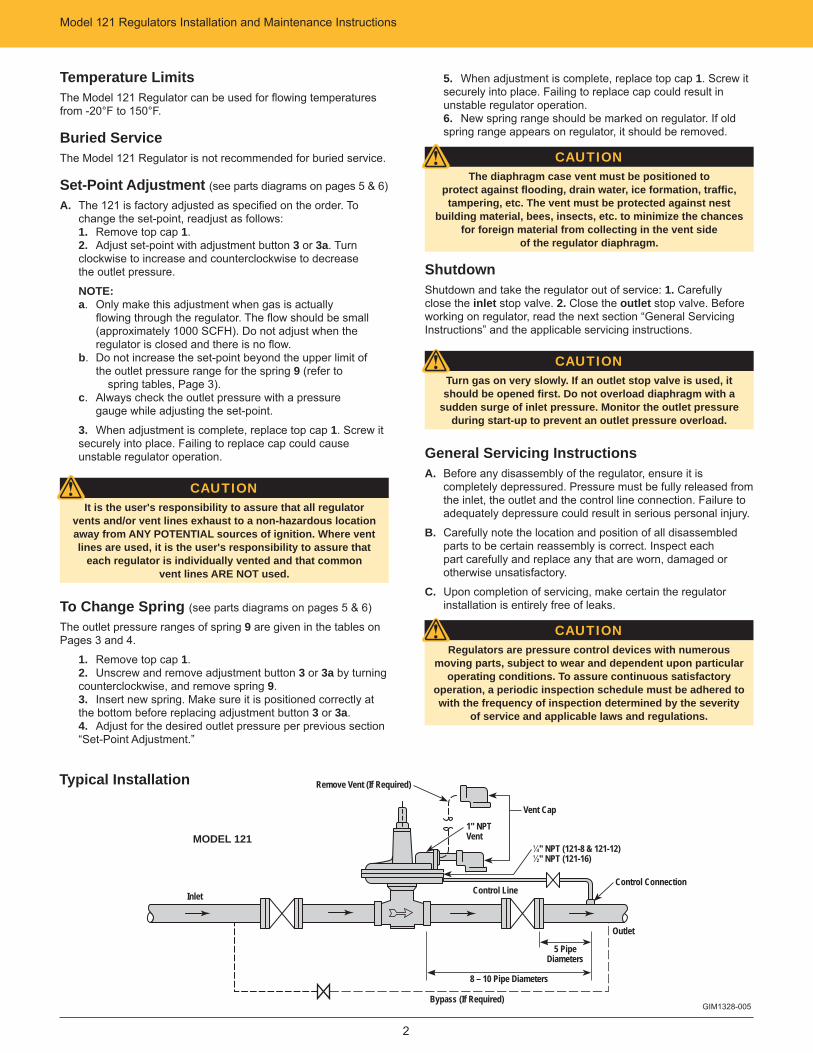
7. The model 121 Regulator is usually right side-up as shown on the Typical Installation drawing (See Page 2.) It may, however, be installed upside down. When inverted it may be necessary to readjust the set-point.
Caution: Do not install sideways. The diaphragm should be horizontal.
8. Install the control line. Connect it into the outlet piping at least 8-10 pipe diameters downstream from the regulator.
Cautions:a. On backpressure regulators and relief valves the external control line connects into the inlet piping, 5 pipe diameters upstream from the regulator.b. Do not install any automatic shutoff device that closes completely between the regulator and the control line connection into the piping.
To avoid excessive turbulence, the connection should be clean and smooth on the inside and be located in straight pipe clear of valves and fi ttings. Keep the inside of the control line clean and protect it from corrosion. Pitch it away from the regulator and avoid moisture pockets. It must be strong (¼" for 121-8 and 121-12, ½" for 121-16, or larger steel tubing or pipe is preferred). It must be well protected against breakage.
Regulator will open wide if the control line breaks.
9. On indoor installations requiring venting outdoors, run the vent piping as short and direct as possible with minimum bends and elbows. Use the same size or larger pipe as the vent connections on the regulator. With natural gas, or any other hazardous gas, vent to a safe place outdoors in case gas should accidentally be discharged. Screen and protect the opening outdoors to guard against water, ice, dirt, debris or insects.
10. Make sure the regulator is correctly connected and adequately supported. Ensure all pipe joints are tight.
Start-UpA. The inlet and outlet shutoff valves should both be closed. If a
by-pass is used, the by-pass valve should also be closed.
B. Note the set-point (set-point is the outlet pressure the regulator is adjusted to deliver). Regulator is factory adjusted to the set-point specifi ed on the order.
Caution: This caution applies where the piping downstream of the outlet shutoff valve is pressured. That pressure must not exceed the regulator set-point by more than the pressure noted (see “Maximum Emergency Pressures”, Page 21).
C. Slowly and carefully open the inlet shutoff valve just enough to allow inlet pressure to build up slowly in the regulator until it is fully pressured.
Caution: During start-up a pressure gauge must be used on the regulator outlet pressure and carefully watched. While inlet pressure builds up, outlet pressure must not exceed set-point by more than 1 psi. If outlet pressure begins to exceed set-point by more than 1 psi, close the inlet shutoff valve. This indicates the regulator is not closing properly. Check and make necessary corrections before proceeding with start-up. If regulator outlet pressure exceeds set-point by more than the pressure noted, refer to “Maximum Emergency Pressures”, Page 21 for instructions.
D. Check installation for leaks.
E. Slowly open the outlet shutoff valve to allow a small fl ow (approximately 1000 SCFH). Make sure the fl ow of gas does not create a hazard.
NOTE: If piping downstream of outlet shutoff valve is pressured, see “Caution” under B.
F. With gas fl owing, check for correct inlet and outlet pressures. It may be necessary to further open the inlet shutoff valve to maintain full inlet pressure.
G. Make sure the regulator closes tight (tight lock-up). To do this, reduce fl ow to zero by slowly closing the outlet shutoff valve. Outlet pressure should not exceed set-point by more than 6" w.c.
H. Fully open inlet and outlet shutoff valves slowly and carefully. Watch pressure gauges.
I. Complete start-up by making sure there are no leaks.
NOTEDo not exceed the regulator's pressure ratings. The regulator
outlet has a lower pressure rating than the inlet. Do not expose the regulator outlet or control line to inlet pressure.
Regulator with external control may be used as an upstream monitor or upstream regulator in a monitor set. The control
line must connect into the outlet piping downstream of the downstream regulator.
If the regulator is to be moved to another location, make sure its construction is compatible with the pressure
and fl ow conditions.
Model 121 Regulators Installation and Maintenance Instructions
2
Typical Installation
Temperature LimitsThe Model 121 Regulator can be used for fl owing temperatures from -20°F to 150°F.
Buried ServiceThe Model 121 Regulator is not recommended for buried service.
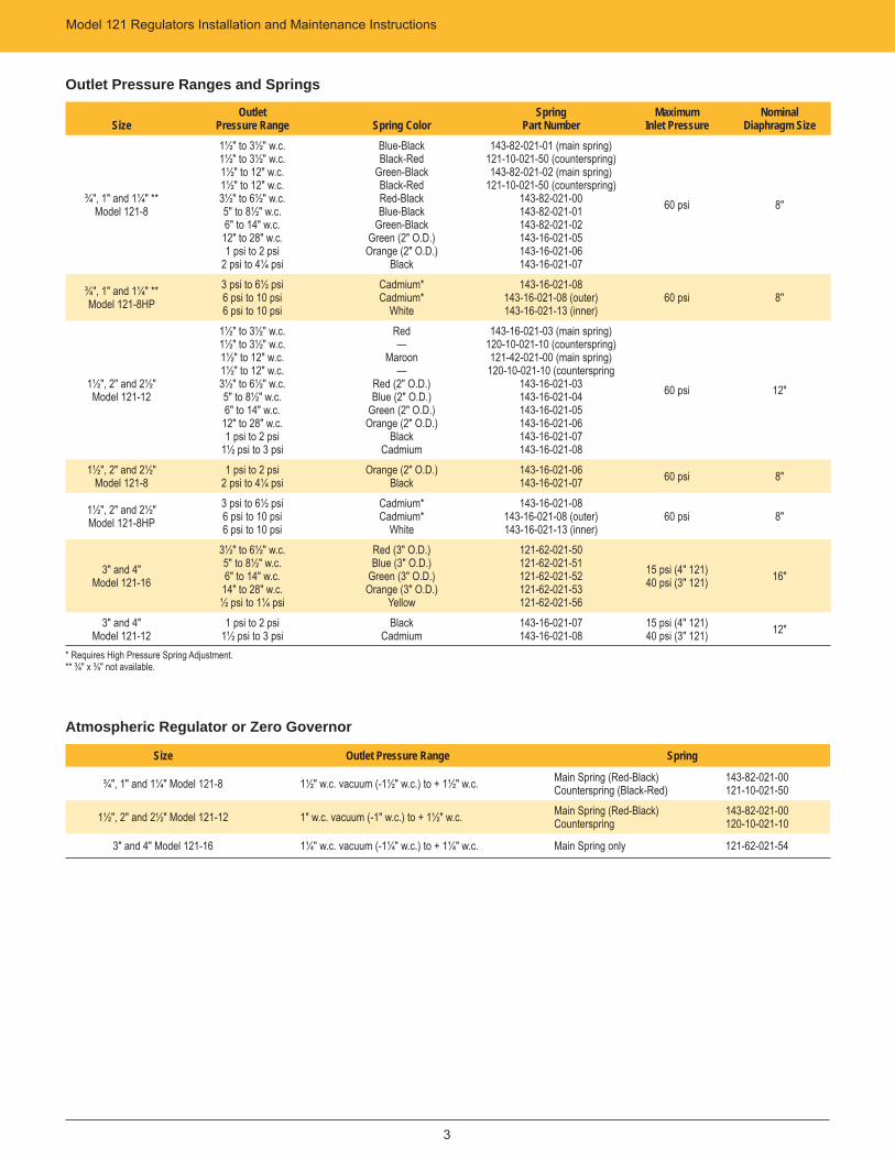
Set-Point Adjustment (see parts diagrams on pages 5 & 6)
A. The 121 is factory adjusted as specifi ed on the order. To change the set-point, readjust as follows: 1. Remove top cap 1.2. Adjust set-point with adjustment button 3 or 3a. Turn clockwise to increase and counterclockwise to decrease the outlet pressure.
NOTE: a. Only make this adjustment when gas is actually fl owing through the regulator. The fl ow should be small (approximately 1000 SCFH). Do not adjust when the regulator is closed and there is no fl ow. b. Do not increase the set-point beyond the upper limit of the outlet pressure range for the spring 9 (refer to spring tables, Page 3). c. Always check the outlet pressure with a pressure gauge while adjusting the set-point.
3. When adjustment is complete, replace top cap 1. Screw it securely into place. Failing to replace cap could cause unstable regulator operation.
CAUTIONIt is the user's responsibility to assure that all regulator
vents and/or vent lines exhaust to a non-hazardous location away from ANY POTENTIAL sources of ignition. Where vent lines are used, it is the user's responsibility to assure that
each regulator is individually vented and that common vent lines ARE NOT used.
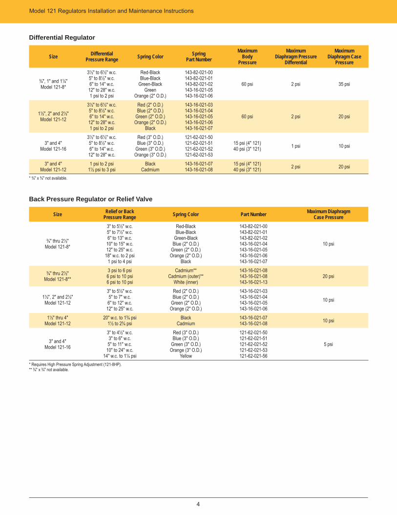
To Change Spring (see parts diagrams on pages 5 & 6)
The outlet pressure ranges of spring 9 are given in the tables on Pages 3 and 4.
1. Remove top cap 1.2. Unscrew and remove adjustment button 3 or 3a by turning counterclockwise, and remove spring 9.3. Insert new spring. Make sure it is positioned correctly at the bottom before replacing adjustment button 3 or 3a.4. Adjust for the desired outlet pressure per previous section “Set-Point Adjustment.”
5. When adjustment is complete, replace top cap 1. Screw it securely into place. Failing to replace cap could result in unstable regulator operation.6. New spring range should be marked on regulator. If old spring range appears on regulator, it should be removed.
CAUTIONThe diaphragm case vent must be positioned to
protect against fl ooding, drain water, ice formation, traffi c, tampering, etc. The vent must be protected against nest
building material, bees, insects, etc. to minimize the chances for foreign material from collecting in the vent side
of the regulator diaphragm.
ShutdownShutdown and take the regulator out of service: 1. Carefully close the inlet stop valve. 2. Close the outlet stop valve. Before working on regulator, read the next section “General Servicing Instructions” and the applicable servicing instructions.
CAUTIONTurn gas on very slowly. If an outlet stop valve is used, it should be opened fi rst. Do not overload diaphragm with a
sudden surge of inlet pressure. Monitor the outlet pressure during start-up to prevent an outlet pressure overload.
General Servicing InstructionsA. Before any disassembly of the regulator, ensure it is
completely depressured. Pressure must be fully released from the inlet, the outlet and the control line connection. Failure to adequately depressure could result in serious personal injury.
B. Carefully note the location and position of all disassembled parts to be certain reassembly is correct. Inspect each part carefully and replace any that are worn, damaged or otherwise unsatisfactory.
C. Upon completion of servicing, make certain the regulator installation is entirely free of leaks.
CAUTIONRegulators are pressure control devices with numerous
moving parts, subject to wear and dependent upon particular operating conditions. To assure continuous satisfactory
operation, a periodic inspection schedule must be adhered to with the frequency of inspection determined by the severity
of service and applicable laws and regulations.
GIM1328-005
Remove Vent (If Required)
Control LineControl Connection
Outlet
Bypass (If Required)
Vent Cap
MODEL 121
5 Pipe Diameters
Inlet
1" NPT Vent
¼" NPT (121-8 & 121-12)½" NPT (121-16)
8 – 10 Pipe Diameters
3
Model 121 Regulators Installation and Maintenance Instructions
Outlet Pressure Ranges and Springs
SizeOutlet
Pressure Range Spring ColorSpring
Part NumberMaximum
Inlet PressureNominal
Diaphragm Size
¾", 1" and 1¼" ** Model 121-8
1½" to 3½" w.c.1½" to 3½" w.c.1½" to 12" w.c.1½" to 12" w.c.3½" to 6½" w.c.5" to 8½" w.c.6" to 14" w.c.
12" to 28" w.c.1 psi to 2 psi
2 psi to 4¼ psi
Blue-BlackBlack-Red
Green-BlackBlack-RedRed-BlackBlue-Black
Green-BlackGreen (2" O.D.)
Orange (2" O.D.)Black
143-82-021-01 (main spring)121-10-021-50 (counterspring)143-82-021-02 (main spring)
121-10-021-50 (counterspring)143-82-021-00143-82-021-01143-82-021-02143-16-021-05143-16-021-06143-16-021-07
60 psi 8"
¾", 1" and 1¼" ** Model 121-8HP
3 psi to 6½ psi6 psi to 10 psi6 psi to 10 psi
Cadmium*Cadmium*
White
143-16-021-08143-16-021-08 (outer)143-16-021-13 (inner)
60 psi 8"
1½", 2" and 2½" Model 121-12
1½" to 3½" w.c.1½" to 3½" w.c.1½" to 12" w.c.1½" to 12" w.c.3½" to 6½" w.c.5" to 8½" w.c.6" to 14" w.c.
12" to 28" w.c.1 psi to 2 psi
1½ psi to 3 psi
Red—
Maroon—
Red (2" O.D.)Blue (2" O.D.)
Green (2" O.D.)Orange (2" O.D.)
BlackCadmium
143-16-021-03 (main spring)120-10-021-10 (counterspring)121-42-021-00 (main spring)
120-10-021-10 (counterspring143-16-021-03143-16-021-04143-16-021-05143-16-021-06143-16-021-07143-16-021-08
60 psi 12"
1½", 2" and 2½" Model 121-8
1 psi to 2 psi2 psi to 4¼ psi
Orange (2" O.D.)Black
143-16-021-06143-16-021-07 60 psi 8"
1½", 2" and 2½" Model 121-8HP
3 psi to 6½ psi6 psi to 10 psi6 psi to 10 psi
Cadmium*Cadmium*
White
143-16-021-08143-16-021-08 (outer)143-16-021-13 (inner)
60 psi 8"
3" and 4" Model 121-16
3½" to 6½" w.c.5" to 8½" w.c.6" to 14" w.c.
14" to 28" w.c.½ psi to 1¼ psi
Red (3" O.D.)Blue (3" O.D.)
Green (3" O.D.)Orange (3" O.D.)
Yellow
121-62-021-50121-62-021-51121-62-021-52121-62-021-53121-62-021-56
15 psi (4" 121)40 psi (3" 121) 16"
3" and 4" Model 121-12
1 psi to 2 psi1½ psi to 3 psi
BlackCadmium
143-16-021-07143-16-021-08
15 psi (4" 121)40 psi (3" 121) 12"
* Requires High Pressure Spring Adjustment.** ¾" x ¾" not available.
Atmospheric Regulator or Zero Governor
Size Outlet Pressure Range Spring
¾", 1" and 1¼" Model 121-8 1½" w.c. vacuum (-1½" w.c.) to + 1½" w.c. Main Spring (Red-Black)Counterspring (Black-Red)
143-82-021-00121-10-021-50
1½", 2" and 2½" Model 121-12 1" w.c. vacuum (-1" w.c.) to + 1½" w.c. Main Spring (Red-Black)Counterspring
143-82-021-00120-10-021-10
3" and 4" Model 121-16 1¼" w.c. vacuum (-1¼" w.c.) to + 1¼" w.c. Main Spring only 121-62-021-54
Model 121 Regulators Installation and Maintenance Instructions
4
Differential Regulator
Size DifferentialPressure Range Spring Color Spring
Part NumberMaximum
BodyPressure
MaximumDiaphragm Pressure
Differential
MaximumDiaphragm Case
Pressure
¾", 1" and 1¼" Model 121-8*
3½" to 6½" w.c.5" to 8½" w.c.6" to 14" w.c.
12" to 28" w.c.1 psi to 2 psi
Red-BlackBlue-Black
Green-BlackGreen
Orange (2" O.D.)
143-82-021-00143-82-021-01143-82-021-02143-16-021-05143-16-021-06
60 psi 2 psi 35 psi
1½", 2" and 2½" Model 121-12
3½" to 6½" w.c.5" to 8½" w.c.6" to 14" w.c.
12" to 28" w.c.1 psi to 2 psi
Red (2" O.D.)Blue (2" O.D.)
Green (2" O.D.)Orange (2" O.D.)
Black
143-16-021-03143-16-021-04143-16-021-05143-16-021-06143-16-021-07
60 psi 2 psi 20 psi
3" and 4" Model 121-16
3½" to 6½" w.c.5" to 8½" w.c.6" to 14" w.c.
12" to 28" w.c.
Red (3" O.D.)Blue (3" O.D.)
Green (3" O.D.)Orange (3" O.D.)
121-62-021-50121-62-021-51121-62-021-52121-62-021-53
15 psi (4" 121)40 psi (3" 121) 1 psi 10 psi
3" and 4" Model 121-12
1 psi to 2 psi1½ psi to 3 psi
BlackCadmium
143-16-021-07143-16-021-08
15 psi (4" 121)40 psi (3" 121) 2 psi 20 psi
* ¾" x ¾" not available.
Back Pressure Regulator or Relief Valve
Size Relief or BackPressure Range Spring Color Part Number Maximum Diaphragm
Case Pressure
¾" thru 2½"Model 121-8*
3" to 5½" w.c.5" to 7½" w.c.6" to 13" w.c.
10" to 15" w.c.12" to 25" w.c.
18" w.c. to 2 psi1 psi to 4 psi
Red-BlackBlue-Black
Green-BlackBlue (2" O.D.)
Green (2" O.D.)Orange (2" O.D.)
Black
143-82-021-00143-82-021-01143-82-021-02143-16-021-04143-16-021-05143-16-021-06143-16-021-07
10 psi
¾" thru 2½" Model 121-8**
3 psi to 6 psi6 psi to 10 psi6 psi to 10 psi
Cadmium**Cadmium (outer)**
White (inner)
143-16-021-08143-16-021-08143-16-021-13
20 psi
1½", 2" and 2½" Model 121-12
3" to 5½" w.c.5" to 7" w.c.
6" to 12" w.c.12" to 25" w.c.
Red (2" O.D.)Blue (2" O.D.)
Green (2" O.D.)Orange (2" O.D.)
143-16-021-03143-16-021-04143-16-021-05143-16-021-06
10 psi
1½" thru 4"Model 121-12
20" w.c. to 1¾ psi1½ to 2¾ psi
BlackCadmium
143-16-021-07143-16-021-08 10 psi
3" and 4"Model 121-16
3" to 4½" w.c.3" to 6" w.c.5" to 11" w.c.
10" to 24" w.c.14" w.c. to 1¼ psi
Red (3" O.D.)Blue (3" O.D.)
Green (3" O.D.)Orange (3" O.D.)
Yellow
121-62-021-50121-62-021-51121-62-021-52121-62-021-53121-62-021-56
5 psi
* Requires High Pressure Spring Adjustment (121-8HP).** ¾" x ¾" not available.
5
Model 121 Regulators Installation and Maintenance Instructions
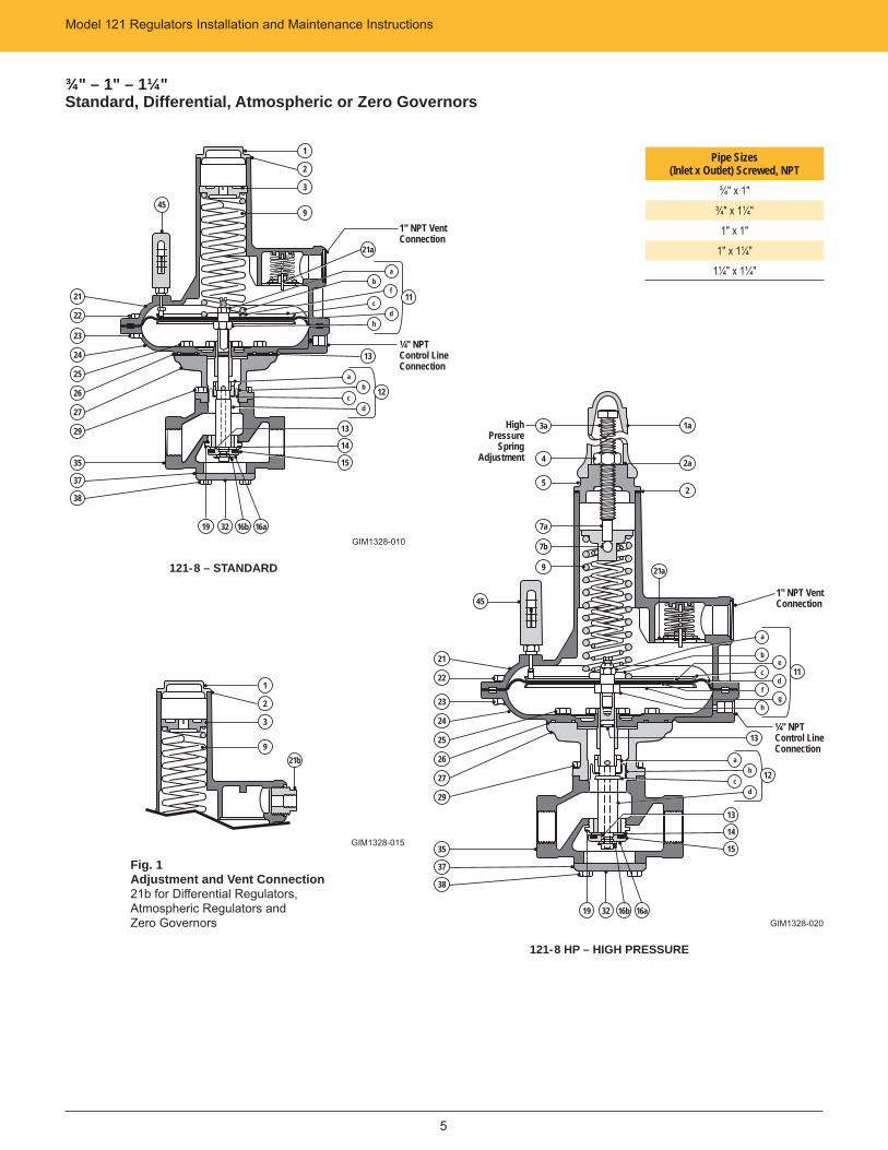
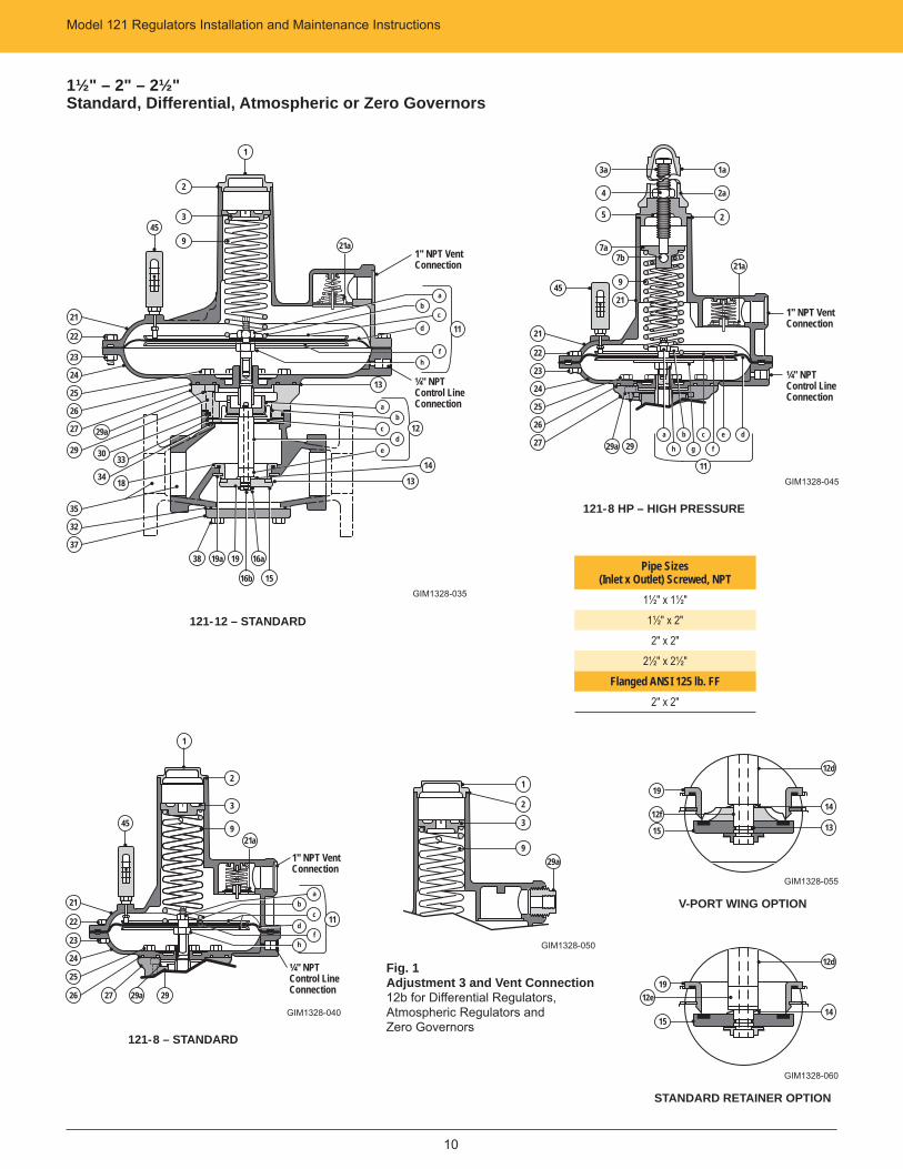
¾" – 1" – 1¼"Standard, Differential, Atmospheric or Zero Governors
Pipe Sizes(Inlet x Outlet) Screwed, NPT
¾" x 1"¾" x 1¼"
1" x 1"1" x 1¼"
1¼" x 1¼"
121-8 – STANDARD
GIM1328-010
121-8 HP – HIGH PRESSURE
GIM1328-020
Fig. 1Adjustment and Vent Connection21b for Differential Regulators, Atmospheric Regulators and Zero Governors
GIM1328-015
a
c
b
h
f
d
11
1
2
3
921b
21
22
23
24
1
2
3
945
25
26
27
29
35
37
38
19 32 16b 16a
13
14
15
ab 12
dc
13¼" NPTControl LineConnection
1" NPT Vent Connection
21a
21
22
23
24
45
25
26
27
29
35
37
38
19 32 16b 16a
13
14
15
ab 12
dc
13¼" NPTControl LineConnection
1a
2a
2
21a
e
f
c
h
d
g
11
1" NPT Vent Connection
b
a
3a
4
5
7a
7b
9
High Pressure
Spring Adjustment
6
Model 121 Regulators Installation and Maintenance Instructions
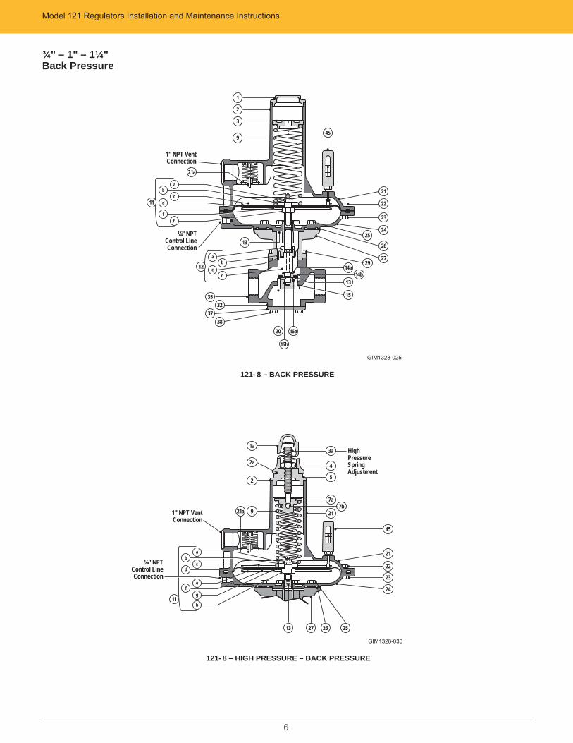
¾" – 1" – 1¼"Back Pressure
121- 8 – BACK PRESSURE
GIM1328-025
121- 8 – HIGH PRESSURE – BACK PRESSURE
GIM1328-030
21
22
23
2425
26
2729
1
2
3
9
3532
37
ab
dc
13¼" NPT
Control LineConnection
c
f
d
h
1" NPT Vent Connection
b
11
21a
a
12
3820
15
16b
16a
45
14a14b
13
21
22
23
24
1a
2a
2
9
¼" NPTControl LineConnection
c
f
d
h
1" NPT Vent Connection
b
11
a
21a
e
g
13 27 26 25
45
3a
4
5
7a7b
21
High Pressure Spring Adjustment
Model 121 Regulators Installation and Maintenance Instructions
7
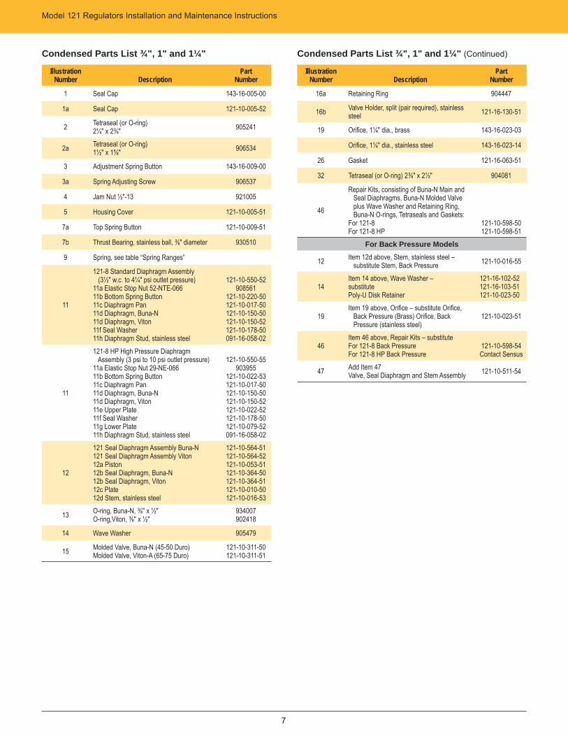
Condensed Parts List ¾", 1" and 1¼"
IllustrationNumber Description
Part Number
1 Seal Cap 143-16-005-00
1a Seal Cap 121-10-005-52
2 Tetraseal (or O-ring)2¼" x 2⅜" 905241
2a Tetraseal (or O-ring)1½" x 1⅝" 906534
3 Adjustment Spring Button 143-16-009-00
3a Spring Adjusting Screw 906537
4 Jam Nut ½"-13 921005
5 Housing Cover 121-10-005-51
7a Top Spring Button 121-10-009-51
7b Thrust Bearing, stainless ball, ⅜" diameter 930510
9 Spring, see table “Spring Ranges”
11
121-8 Standard Diaphragm Assembly (3½" w.c. to 4¼" psi outlet pressure)11a Elastic Stop Nut 52-NTE-06611b Bottom Spring Button 11c Diaphragm Pan 11d Diaphragm, Buna-N 11d Diaphragm, Viton 11f Seal Washer 11h Diaphragm Stud, stainless steel
121-10-550-52908561
121-10-220-50121-10-017-50121-10-150-50121-10-150-52121-10-178-50091-16-058-02
11
121-8 HP High Pressure Diaphragm Assembly (3 psi to 10 psi outlet pressure)11a Elastic Stop Nut 29-NE-066 11b Bottom Spring Button 11c Diaphragm Pan 11d Diaphragm, Buna-N 11d Diaphragm, Viton 11e Upper Plate 11f Seal Washer 11g Lower Plate 11h Diaphragm Stud, stainless steel
121-10-550-55903955
121-10-022-53121-10-017-50121-10-150-50121-10-150-52121-10-022-52121-10-178-50121-10-079-52091-16-058-02
12
121 Seal Diaphragm Assembly Buna-N 121 Seal Diaphragm Assembly Viton 12a Piston 12b Seal Diaphragm, Buna-N 12b Seal Diaphragm, Viton 12c Plate12d Stem, stainless steel
121-10-564-51121-10-564-52121-10-053-51121-10-364-50121-10-364-51121-10-010-50121-10-016-53
13 O-ring, Buna-N, ⅜" x ½" O-ring,Viton, ⅜" x ½"
934007 902418
14 Wave Washer 905479
15 Molded Valve, Buna-N (45-50 Duro) Molded Valve, Viton-A (65-75 Duro)
121-10-311-50 121-10-311-51
Condensed Parts List ¾", 1" and 1¼" (Continued)
IllustrationNumber Description
Part Number
16a Retaining Ring 904447
16b Valve Holder, split (pair required), stainless steel 121-16-130-51
19 Orifi ce, 1¼" dia., brass 143-16-023-03
Orifi ce, 1¼" dia., stainless steel 143-16-023-14
26 Gasket 121-16-063-51
32 Tetraseal (or O-ring) 2⅜" x 2½" 904081
46
Repair Kits, consisting of Buna-N Main and Seal Diaphragms, Buna-N Molded Valve plus Wave Washer and Retaining Ring, Buna-N O-rings, Tetraseals and Gaskets:For 121-8 For 121-8 HP
121-10-598-50121-10-598-51
For Back Pressure Models
12 Item 12d above, Stem, stainless steel – substitute Stem, Back Pressure 121-10-016-55
14 Item 14 above, Wave Washer – substitutePoly-U Disk Retainer
121-16-102-52 121-16-103-51121-10-023-50
19Item 19 above, Orifi ce – substitute Orifi ce, Back Pressure (Brass) Orifi ce, Back Pressure (stainless steel)
121-10-023-51
46Item 46 above, Repair Kits – substituteFor 121-8 Back PressureFor 121-8 HP Back Pressure
121-10-598-54Contact Sensus
47 Add Item 47Valve, Seal Diaphragm and Stem Assembly 121-10-511-54
8
Model 121 Regulators Installation and Maintenance Instructions
8
Servicing – ¾", 1", 1¼"General Instructions1. Make sure the regulator is entirely depressured
before servicing.
2. Carefully note location and position of all disassembled parts to be certain reassembly is correct. Inspect each one carefully and replace those that are worn or damaged or otherwise unsatisfactory.
3. A moderate application of lubricant to O-ring 13 will ensure free stem movement and a tight seal. Similar application of lubricant to other O-rings or Tetraseals will ensure their tightness. Do not use petroleum based lubricants.
4. Bolted connections should be tightened evenly and fi rmly. Carefully tighten diaphragms into place. Bolts must be tight enough to prevent leakage, but not so tight that the diaphragm material is crushed or damaged.
5. Upon completion of servicing, make certain that regulator installation is entirely free of leaks.
To Service Valve – 151. Remove bolts 38 and remove bottom cap 37 and
Tetraseal 32.
2. Remove Retaining Ring 16a.
3. Remove both halves of valve holder 16b.
4. Remove valve 15 (wave washer 14 will likely remove with the valve). Retain it for reassembly
– To reassemble, replace parts in reverse sequence.
To Service Main Diaphragm – 11d1. Remove top cap 1, and release and remove adjustment
3 or 3a. On high pressure model remove cap 1a, release adjustment 3a, and remove cover 5 and button 7a. Mark or measure position of adjustment 3 or 3a. Use this to return adjustment to this setting during assembly.
2. Remove spring 9.
3. Remove bolts 22 and upper case 21.
4. Rotate diaphragm assembly 11 counterclockwise (this unscrews 11h from 12d) and remove.
5. To disassemble diaphragm assembly, remove nut 11a. Carefully note location and position of all parts to be certain of correct reassembly. Abrasive side of emery cloth washers face against diaphragm.
– To reassemble, replace parts in reverse sequence. Make sure the screwed connection between 11h and 12d is loosened approximately one-half turn. To do this, carefully rotate diaphragm assembly 11 clockwise until this screwed connection bottoms (do not jam it together). Then, back-off diaphragm assembly 11 counter-clockwise approximately one-half turn. The 11h and 12d screwed connection must not be tight.
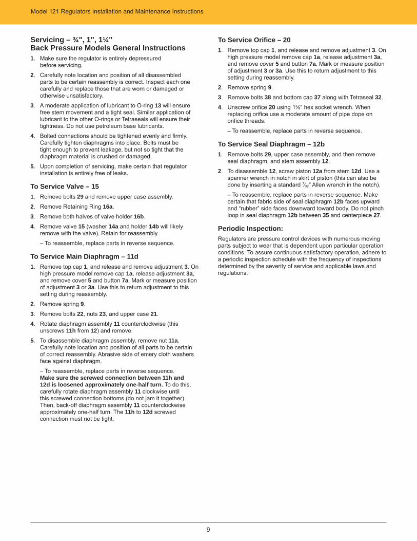
To Service Orifi ce – 191. Remove valve 15 per section “To Service Valve – 15”.
2. Unscrew orifi ce 19 using 1⅝" hex socket wrench. When replacing orifi ce use a moderate amount of pipe dope on orifi ce threads.
To Service Seal Diaphragm – 12b1. Remove valve 15 per section “To Service Valve – 15”.
2. Remove diaphragm assembly 11 per section “To Service Main Diaphragm – 11d”.
3. Remove bolts 25 and lower diaphragm case 24.
4. Remove bolts 29 and center piece 27, and then remove seal diaphragm assembly 12.
5. To disassemble 12, unscrew piston 12a from stem 12d. Use a spanner wrench in notch in skirt of piston (this can also be done by inserting a standard 7⁄32" Allen wrench in the notch).
– To reassemble, replace parts in reverse sequence. Make certain fabric side of seal diaphragm 12b faces upward and “rubber” side faces downward toward body. Do not pinch loop in seal diaphragm 12b between 35 and centerpiece 27.
Periodic Inspection:Regulators are pressure control devices with numerous moving parts subject to wear that is dependent upon particular operation conditions. To assure continuous satisfactory operation, adhere to a periodic inspection schedule with the frequency of inspections determined by the severity of service and applicable laws and regulations.
Model 121 Regulators Installation and Maintenance Instructions
9
Servicing – ¾", 1", 1¼"Back Pressure Models General Instructions1. Make sure the regulator is entirely depressured
before servicing.
2. Carefully note location and position of all disassembled parts to be certain reassembly is correct. Inspect each one carefully and replace those that are worn or damaged or otherwise unsatisfactory.
3. A moderate application of lubricant to O-ring 13 will ensure free stem movement and a tight seal. Similar application of lubricant to the other O-rings or Tetraseals will ensure their tightness. Do not use petroleum base lubricants.
4. Bolted connections should be tightened evenly and fi rmly. Carefully tighten diaphragms into place. Bolts must be tight enough to prevent leakage, but not so tight that the diaphragm material is crushed or damaged.
5. Upon completion of servicing, make certain that regulator installation is entirely free of leaks.
To Service Valve – 151. Remove bolts 29 and remove upper case assembly.
2. Remove Retaining Ring 16a.
3. Remove both halves of valve holder 16b.
4. Remove valve 15 (washer 14a and holder 14b will likely remove with the valve). Retain for reassembly.
– To reassemble, replace parts in reverse sequence.
To Service Main Diaphragm – 11d1. Remove top cap 1, and release and remove adjustment 3. On
high pressure model remove cap 1a, release adjustment 3a, and remove cover 5 and button 7a. Mark or measure position of adjustment 3 or 3a. Use this to return adjustment to this setting during reassembly.
2. Remove spring 9.
3. Remove bolts 22, nuts 23, and upper case 21.
4. Rotate diaphragm assembly 11 counterclockwise (this unscrews 11h from 12) and remove.
5. To disassemble diaphragm assembly, remove nut 11a. Carefully note location and position of all parts to be certain of correct reassembly. Abrasive side of emery cloth washers face against diaphragm.
– To reassemble, replace parts in reverse sequence. Make sure the screwed connection between 11h and 12d is loosened approximately one-half turn. To do this, carefully rotate diaphragm assembly 11 clockwise until this screwed connection bottoms (do not jam it together). Then, back-off diaphragm assembly 11 counterclockwise approximately one-half turn. The 11h to 12d screwed connection must not be tight.
To Service Orifi ce – 201. Remove top cap 1, and release and remove adjustment 3. On
high pressure model remove cap 1a, release adjustment 3a, and remove cover 5 and button 7a. Mark or measure position of adjustment 3 or 3a. Use this to return adjustment to this setting during reassembly.
2. Remove spring 9.
3. Remove bolts 38 and bottom cap 37 along with Tetraseal 32.
4. Unscrew orifi ce 20 using 1⅝" hex socket wrench. When replacing orifi ce use a moderate amount of pipe dope on orifi ce threads.
– To reassemble, replace parts in reverse sequence.
To Service Seal Diaphragm – 12b1. Remove bolts 29, upper case assembly, and then remove
seal diaphragm, and stem assembly 12.
2. To disassemble 12, screw piston 12a from stem 12d. Use a spanner wrench in notch in skirt of piston (this can also be done by inserting a standard 7⁄32" Allen wrench in the notch).
– To reassemble, replace parts in reverse sequence. Make certain that fabric side of seal diaphragm 12b faces upward and “rubber” side faces downward toward body. Do not pinch loop in seal diaphragm 12b between 35 and centerpiece 27.
Periodic Inspection:Regulators are pressure control devices with numerous moving parts subject to wear that is dependent upon particular operation conditions. To assure continuous satisfactory operation, adhere to a periodic inspection schedule with the frequency of inspections determined by the severity of service and applicable laws and regulations.
Model 121 Regulators Installation and Maintenance Instructions
10
1½" – 2" – 2½"Standard, Differential, Atmospheric or Zero Governors
Pipe Sizes(Inlet x Outlet) Screwed, NPT
1½" x 1½"1½" x 2"2" x 2"
2½" x 2½"Flanged ANSI 125 lb. FF
2" x 2"
121-8 – STANDARD
GIM1328-040
121-12 – STANDARD
GIM1328-035
121-8 HP – HIGH PRESSURE
GIM1328-045
V-PORT WING OPTION
STANDARD RETAINER OPTION
21a
1
2
3
945
21
22
23
24
25
26
27
29
35
32
37
29a
3033
3418
19a 1938
16b
16a
15
a
d
b
h
c
f
11
¼" NPT Control Line Connection
14
ab
12d
c
13
e
13
1" NPT Vent Connection
21a
¼" NPT Control Line Connection
1" NPT Vent Connection
21a
1a
2a
2
45
3a
4
5
7b
9
21
7a
21
22
23
24
25
26
27 29a 29a db c e
fh g
11
Fig. 1Adjustment 3 and Vent Connection12b for Differential Regulators, Atmospheric Regulators and Zero Governors
1
2
3
929a
45
21
22
23
24
25
26 27 2929a
¼" NPTControl LineConnection
1
2
3
9
bc 11f
d
h
a
1" NPT Vent Connection
12d
14
13
19
12f
15
12d
14
1912e
15
GIM1328-050
GIM1328-055
GIM1328-060
Model 121 Regulators Installation and Maintenance Instructions
11
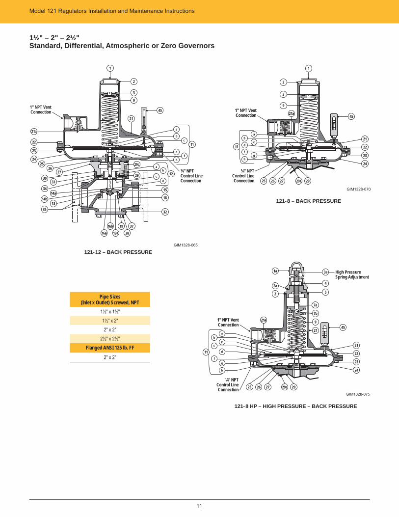
1½" – 2" – 2½"Standard, Differential, Atmospheric or Zero Governors
Pipe Sizes(Inlet x Outlet) Screwed, NPT
1½" x 1½"1½" x 2"2" x 2"
2½" x 2½"Flanged ANSI 125 lb. FF
2" x 2"
121-12 – BACK PRESSUREGIM1328-065
121-8 – BACK PRESSURE
GIM1328-070
121-8 HP – HIGH PRESSURE – BACK PRESSURE
GIM1328-075
1
21a
22
23
2425
2627
14a14b
35
19a1916b
16a
ab
12d
c
15
¼" NPT Control LineConnection
2
3
9
c
d
hf
11
1" NPT Vent Connection
b
a
21
45
3033
34
13
3837
18
32
29
29c
2
3
9
1
1" NPT Vent Connection
c
f
hg
ba
11 d
21a
21
22
23
24
25 26 27 29a 29
45
¼" NPTControl LineConnection
3a
4
5
High Pressure Spring Adjustment
21a
45
7b
9
21
7a
21
22
23
24
1" NPT Vent Connection
¼" NPTControl LineConnection
f
c
b
11
e
h
a
d
g
25 26 27 29a 29
1a
2a
2
Model 121 Regulators Installation and Maintenance Instructions
12
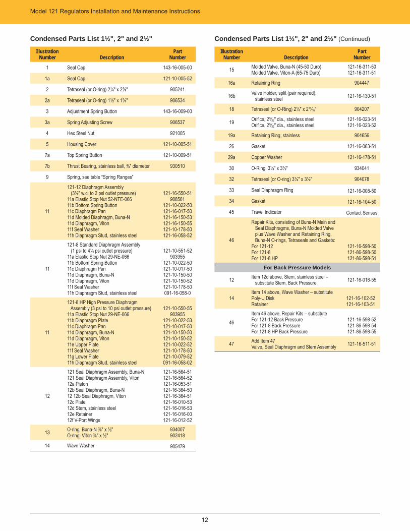
Condensed Parts List 1½", 2" and 2½"
IllustrationNumber Description
Part Number
1 Seal Cap 143-16-005-00
1a Seal Cap 121-10-005-52
2 Tetraseal (or O-ring) 2¼" x 2⅜" 905241
2a Tetraseal (or O-ring) 1½" x 1⅝" 906534
3 Adjustment Spring Button 143-16-009-00
3a Spring Adjusting Screw 906537
4 Hex Steel Nut 921005
5 Housing Cover 121-10-005-51
7a Top Spring Button 121-10-009-51
7b Thrust Bearing, stainless ball, ⅜" diameter 930510
9 Spring, see table “Spring Ranges”
11
121-12 Diaphragm Assembly (3½" w.c. to 2 psi outlet pressure) 11a Elastic Stop Nut 52-NTE-066 11b Bottom Spring Button11c Diaphragm Pan 11d Molded Diaphragm, Buna-N 11d Diaphragm, Viton 11f Seal Washer 11h Diaphragm Stud, stainless steel
121-16-550-51908561
121-10-022-50121-16-017-50121-16-150-53121-16-150-55121-10-178-50121-16-058-52
11
121-8 Standard Diaphragm Assembly (1 psi to 4¼ psi outlet pressure)11a Elastic Stop Nut 29-NE-066 11b Bottom Spring Button 11c Diaphragm Pan 11d Diaphragm, Buna-N 11d Diaphragm, Viton 11f Seal Washer 11h Diaphragm Stud, stainless steel
121-10-551-52903955
121-10-022-50121-10-017-50121-10-150-50121-10-150-52121-10-178-50091-16-058-0
11
121-8 HP High Pressure Diaphragm Assembly (3 psi to 10 psi outlet pressure)11a Elastic Stop Nut 29-NE-06611b Diaphragm Plate 11c Diaphragm Pan 11d Diaphragm, Buna-N 11d Diaphragm, Viton 11e Upper Plate 11f Seal Washer11g Lower Plate 11h Diaphragm Stud, stainless steel
121-10-550-55903955
121-10-022-53121-10-017-50121-10-150-50121-10-150-52121-10-022-52121-10-178-50121-10-079-52091-16-058-02
12
121 Seal Diaphragm Assembly, Buna-N 121 Seal Diaphragm Assembly, Viton 12a Piston 12b Seal Diaphragm, Buna-N 12 12b Seal Diaphragm, Viton 12c Plate 12d Stem, stainless steel 12e Retainer 12f V-Port Wings
121-16-564-51121-16-564-52121-16-053-51121-16-364-50121-16-364-51121-16-010-53121-16-016-53121-16-016-00121-16-012-52
13 O-ring, Buna-N ⅜" x ½" O-ring, Viton ⅜" x ½"
934007902418
14 Wave Washer 905479
Condensed Parts List 1½", 2" and 2½" (Continued)
IllustrationNumber Description
Part Number
15 Molded Valve, Buna-N (45-50 Duro) Molded Valve, Viton-A (65-75 Duro)
121-16-311-50 121-16-311-51
16a Retaining Ring 904447
16b Valve Holder, split (pair required), stainless steel 121-16-130-51
18 Tetraseal (or O-Ring) 2½" x 211⁄16" 904207
19 Orifi ce, 25⁄32" dia., stainless steelOrifi ce, 25⁄32" dia., stainless steel
121-16-023-51121-16-023-52
19a Retaining Ring, stainless 904656
26 Gasket 121-16-063-51
29a Copper Washer 121-16-178-51
30 O-Ring, 3⅛" x 3½" 934041
32 Tetraseal (or O-ring) 3¼" x 3½" 904078
33 Seal Diaphragm Ring 121-16-008-50
34 Gasket 121-16-104-50
45 Travel Indicator Contact Sensus
46
Repair Kits, consisting of Buna-N Main and Seal Diaphragms, Buna-N Molded Valve plus Wave Washer and Retaining Ring, Buna-N O-rings, Tetraseals and Gaskets:For 121-12For 121-8 For 121-8 HP
121-16-598-50121-86-598-50121-86-598-51
For Back Pressure Models
12 Item 12d above, Stem, stainless steel – substitute Stem, Back Pressure 121-16-016-55
14 Item 14 above, Wave Washer – substitutePoly-U Disk Retainer
121-16-102-52 121-16-103-51
46Item 46 above, Repair Kits – substituteFor 121-12 Back PressureFor 121-8 Back PressureFor 121-8 HP Back Pressure
121-16-598-52121-86-598-54121-86-598-55
47 Add Item 47 Valve, Seal Diaphragm and Stem Assembly 121-16-511-51
Model 121 Regulators Installation and Maintenance Instructions
13
Servicing – 1½", 2", 2½"General Instructions1. Make sure the regulator is entirely depressured
before servicing.
2. Carefully note location and position of all disassembled parts to be certain reassembly is correct. Inspect each one carefully and replace those that are worn or damaged or otherwise unsatisfactory.
3. A moderate application of lubricant to O-ring 13 will ensure free stem movement and a tight seal. Similar application of lubricant to other O-rings or Tetraseals will ensure their tightness. Do not use petroleum base lubricants.
4. Bolted connections should be tightened evenly and fi rmly. Carefully tighten diaphragms into place. Bolts must be tight enough to prevent leakage, but not so tight that the diaphragm material is crushed or damaged.
5. Upon completion of servicing, make certain that regulator installation is entirely free of leaks.
To Service Valve – 151. Remove bolts 38 and remove bottom cap 37 and
Tetraseal 32.
2. Remove Retaining Ring 16a.
3. Remove both halves of valve holder 16b.
4. Remove valve 15 (wave washer 14 will likely remove with the valve). Retain for reassembly.
– To reassemble, replace parts in reverse sequence.
To Install V-Port Wing – 12f1. Remove valve 15 per section “To Service Valve – 15”.
2. Remove wave washer 14.
3. Remove retainer 12e. It will not be used.
4. Reinstall wave washer 14.
5. Install V-Port wing 12f on stem with v-notch side against the wave washer and fl at area exposed.
6. Reassemble remaining parts in reverse sequence.
To Service Main Diaphragm – 11d1. Remove top cap 1, and release and remove adjustment 3. On
high pressure model remove cap 1a, release adjustment 3a, and remove cover 5 and button 7a. Mark or measure position of adjustment 3 or 3a. Use this to return adjustment to this setting during reassembly.
2. Remove spring 9.
3. Remove bolts 22 and upper case 21.
4. Rotate diaphragm assembly 11 counterclockwise (this unscrews 11h from 12d) and remove.
5. To disassemble diaphragm assembly, remove nut 11a. Carefully note location and position of all parts to be certain of correct reassembly. Abrasive side of emery cloth washers face against diaphragm.
– To reassemble, replace parts in reverse sequence. Make sure the screwed connection between 11h and 12d is loosened approximately one-half turn. To do this, carefully rotate diaphragm assembly 11 clockwise until this screwed connection bottoms (do not jam it together). Then back-off diaphragm assembly 11 counterclockwise approximately one-half turn. The 11h to 12d screwed connection must not be tight.
To Service Orifi ce – 191. Remove valve 15 per section “To Service Valve – 15”.
2. Remove main diaphragm assembly 11 per steps 1 through 4 “To Service Main Diaphragm – 11d”.
3. Remove seal diaphragm assembly 12 per steps 3 and 4 under “To Service Seal Diaphragm – 12b”.
4. Remove Retaining Ring 19a.
5. Remove orifi ce 19 through top opening.
– To reassemble, replace parts in reverse sequence. (On reassembly, ensure that 19a is fully seated in its groove. Also, beveled edge of 19a faces downward toward bottom cap 37.)
To Service Seal Diaphragm – 12b1. Remove valve 15 per section “To Service Valve – 15”.
2. Remove main diaphragm assembly 11 per steps 1 through 4 under “To Service Main Diaphragm – 11d”.
3. Remove bolts 25 and lower diaphragm case 24.
4. Remove bolts 29 and centerpiece 27, and then remove seal diaphragm assembly 12.
5. To disassemble 12, unscrew piston 12a from stem 12d. Use a spanner wrench in notch in skirt of piston (this can also be done by inserting a standard 7⁄32" Allen wrench in the notch).
– To reassemble, replace parts in reverse sequence. Make certain that fabric side of seal diaphragm 12b faces upward and “rubber” side faces downward toward body. Do not pinch loop in seal diaphragm 12b between ring 33 and centerpiece 27. Also, rounded edge of 33 faces upward toward seal diaphragm 12b.
Periodic Inspection:Regulators are pressure control devices with numerous moving parts subject to wear that is dependent upon particular operation conditions. To assure continuous satisfactory operation, adhere to a periodic inspection schedule with the frequency of inspections determined by the severity of service and applicable laws and regulations.
Model 121 Regulators Installation and Maintenance Instructions
14
Servicing – 1½", 2", 2½" Back Pressure ModelsGeneral Instructions1. Make sure the regulator is entirely depressured
before servicing.
2. Carefully note location and position of all disassembled parts to be certain reassembly is correct. Inspect each one carefully and replace those that are worn or damaged or otherwise unsatisfactory.
3. A moderate application of lubricant to O-ring 13 will ensure free stem movement and a tight seal. Similar application of lubricant to other O-rings or Tetraseals will ensure their tightness. Do not use petroleum base lubricants.
4. Bolted connections should be tightened evenly and fi rmly. Carefully tighten diaphragms into place. Bolts must be tight enough to prevent leakage, but not so tight that the diaphragm material is crushed or damaged.
5. Upon completion of servicing, make certain that regulator installation is entirely free of leaks.
To Service Main Diaphragm – 11d1. Remove top cap 1, and release and remove adjustment 3. On
high pressure model remove cap 1a, release adjustment 3a, and remove cover 5 and button 7a. Mark or measure position of adjustment 3 or 3a. Use this to return adjustment to this setting during reassembly.
2. Remove spring 9.
3. Remove bolts 22, nuts 23 and upper case 21.
4. Rotate diaphragm assembly 11 counterclockwise (this unscrews 11h from 12) and remove.
5. To disassemble diaphragm assembly, remove nut 11a. Carefully note location and position of all parts to be certain of correct reassembly. Abrasive side of emery cloth washers face against diaphragm.
– To reassemble, replace parts in reverse sequence. Make sure the screwed connection between 11h and 12d is loosened approximately one-half turn. To do this, carefully rotate diaphragm assembly 11 clockwise until this screwed connection bottoms (do not jam it together). Then, back-off diaphragm assembly 11 counterclockwise approximately one-half turn. The 11h to 12d screwed connection must not be tight.
To Service Seal Diaphragm – 12b1. Remove main diaphragm assembly 11 per steps 1 through 4
“To Service Main Diaphragm – 11d”.
2. Remove bolts 29 and centerpiece 27, then remove seal diaphragm, valve and stem assembly 12.
3. To disassemble 12, unscrew piston 12a from stem 12d. Use a spanner wrench in notch in skirt of piston (this can also be done by inserting a standard 7⁄32" Allen wrench in the notch).
– To reassemble, replace parts in reverse sequence. Make certain that fabric side of seal diaphragm 12b faces upward and “rubber” side faces downward toward body. Do not pinch loop on seal diaphragm 12b between ring 33 and centerpiece 27, Also rounded edge of 33 faces upward toward seal diaphragm 12b.
To Service Valve – 151. Remove main diaphragm assembly 11 per steps 1 through 4
under “To Service Main Diaphragm – 11d”.
2. Remove seal diaphragm, valve and stem assembly to service seal diaphragm 12b.
3. Remove Retaining Ring 16a.
4. Remove both halves of valve holder 16b.
5. Remove valve 15 (washer 14 and holder 14a will likely remove with the valve). Retain for reassembly.
– To reassemble, replace parts in reverse sequence.
To Service Orifi ce – 191. Remove main diaphragm assembly 11 per steps 1 through 4
under “To Service Seal Diaphragm – 11d”.
2. Remove seal diaphragm, valve and stem assembly 12 per steps 2 and 3 under “To Service Seal Diaphragm – 12b”.
3. Remove Retaining Ring 19a through top opening.
4. Remove orifi ce 19 through bottom opening.
– To reassemble, replace parts in reverse sequence. (On reassembly, be sure that 19a is fully seated in its groove. Also, beveled edge of 19a faces upward toward adapter 27.)
Periodic Inspection:Regulators are pressure control devices with numerous moving parts subject to wear that is dependent upon particular operation conditions. To assure continuous satisfactory operation, adhere to a periodic inspection schedule with the frequency of inspections determined by the severity of service and applicable laws and regulations.
Model 121 Regulators Installation and Maintenance Instructions
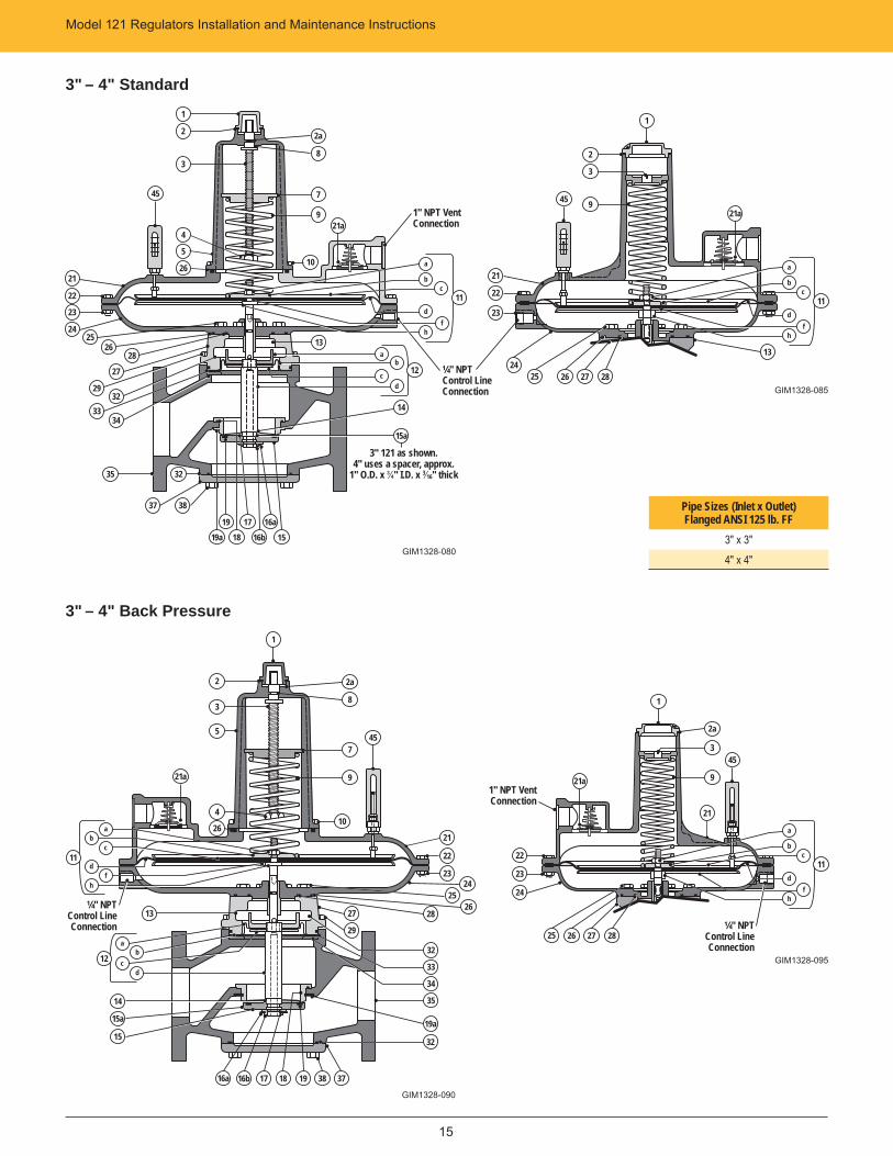
15
Pipe Sizes (Inlet x Outlet)Flanged ANSI 125 lb. FF
3" x 3"4" x 4"
3" – 4" Standard
3" – 4" Back Pressure
35 32
37 38
GIM1328-095
45
GIM1328-090
GIM1328-085
GIM1328-080
45
2a
8
745
2
3
9
1
21a
16a 16b 17 18 19
1" NPT Vent Connection
9
10
¼" NPTControl LineConnection
c
d
hf
11
b
a
ab
12d
c
14
13
22
23
2425
26
27
2932
33
181719
19a 16b16a
15a
3" 121 as shown.4" uses a spacer, approx.
1" O.D. x ¾" I.D. x 3⁄16" thick
34
c
d
hf
11
b
a
13
25 26 27 28
22
23
24
21
21a
2a
8
745
9
10
2
3
5
1
4
26
h
d
b
11c
a
f
2a
3
9
¼" NPTControl LineConnection
c
f
11d
h
b
a
25 26 27 28
22
23
24
1
21a21a
ab
dc
13
12
14
15a
1519a
32
38 37
22
2324
2526
28
35
32
33
34
27
29
¼" NPTControl LineConnection
1" NPT Vent Connection
1
2
3
4
5
2621
28
15
21
21
Model 121 Regulators Installation and Maintenance Instructions
16
Condensed Parts List 3" and 4"
IllustrationNumber Description
Part Number
3" and 4" Model 121
1 Seal Cap for 121-16Seal Cap for 121-12
138-02-005-01143-16-005-00
2 Seal Cap Gasket for 121-16Tetraseal for 121-12, 2¼" x 2⅜"
120-08-066-00905241
3 Adjustment Spring Button for 121-12 143-16-009-00
8 Thrust Washer 141-10-160-01
9 Spring see table “Spring Ranges”
11
121-16 Diaphragm Assembly 11a Elastic Stop Nut 52-NTE-06611b Bottom Spring Button 11c Diaphragm Pan11d Diaphragm, Buna-N11d Diaphragm, Viton11f Seal Washer 11h Diaphragm Stud, stainless steel
121-62-550-50903955
121-62-022-50121-62-017-50121-62-150-50121-62-150-52121-10-178-50121-16-058-52
11
121-12 Diaphragm Assembly (3½" w.c. to 2 psi outlet pressure)11a Elastic Stop nut 29-NE-06611b Bottom Spring Button 11c Diaphragm Pan 11d Molded Diaphragm, Buna-N 11d Diaphragm, Viton 11f Seal Washer 11h Diaphragm Stud, stainless steel
121-16-550-51903955
121-10-022-50121-16-017-50121-16-150-53121-16-150-55121-10 178-50121-16-058-52
13 O-ring, Buna-N, ⅜" x ½" O-ring, Viton, ⅜" x ½"
934007902418
14 Wave Washer 905481
16a Retaining Ring 904448
16b Valve Holder, split (pair required), stainless steel 121-22-130-51
17 O-ring, Buna-N, ⅝" x ¾" O-ring, Viton, ⅝" x ¾"
902922902698
26 Tetraseal (or O-ring) 4⅜" x 4⅝" 904085
28 Tetraseal (or O-ring) 2¾" x 3" 904079
46
Repair Kits, consisting of Buna-N Main and Seal Diaphragm, Buna-N Molded Valve plus Wave Washer and Retaining Ring, Buna-NO-rings, Tetraseals and Gaskets3" 121-163" 121-124" 121-164" 121-12
121-60-598-50121-20-598-50121-62-598-50121-22-598-50
For Back Pressure Models
14Item 14 above, Wave Washer – substitutePoly-U Disk Retainer
121-22-102-52121-22-103-50
Condensed Parts List 3" and 4" (Continued)
IllustrationNumber Description
Part Number
3" Model 121
12
12a Piston 12b Seal Diaphragm, Buna-N 12b Seal Diaphragm, Viton 12c Plate 12d Stem, stainless steel
121-20-053-50121-20-364-50121-20-364-51121-20-010-50121-20-016-51
15 Molded Valve, Buna-N (45-50 Duro) Molded Valve, Viton-A (65-75 Duro)
121-20-311-50121-20-311-51
15a Valve Wing Valve Wing, stainless steel
121-20-018-50121-20-018-51
18 Tetraseal (or O-ring) 3¾" x 4" 904200
19 Orifi ce, 3¼" dia., steel Orifi ce, 3¼" dia., stainless steel
121-20-023-50121-20-023-51
19a Retaining Ring, stainless 904660
32 Tetraseal (or O-ring) 5" x 5¼" 934328
33 Seal Diaphragm Ring 121-20-008-50
34 Gasket 121-20-104-50
45 Travel Indicator (specify scale 091-00-008-02) 091-00-365-00For Back Pressure Models
12 Item 12d above, Stem – substitute Stem, Back Pressure 121-20-016-53
47 Add item 47 Valve, Seal Diaphragm and Stem Assembly 121-20-511-50
4" Model 121 only
12
12a Piston 12b Seal Diaphragm, Buna-N 12b Seal Diaphragm, Viton 12c Plate 12d Stem, steel 12d Stem, stainless steel
121-22-053-50121-22-264-50121-22-364-51121-22-010-50121-22-016-53121-22-016-51
15 Molded Valve, Buna-N (45-50 Duro) Molded Valve, Viton-A (65-75 Duro)
121-22-311-50121-22-311-51
15a Valve Spacer 121-22-038-50
18 Tetraseal (or O-ring) 4¾" x 5" 950625
19 Orifi ce, 47⁄32" dia., steel 121-22-023-50
19a Retaining Ring 904229
20 Orifi ce, 47⁄32" dia., stainless steel 121-22-023-52
20a Retaining Ring, stainlessPliers for Retaining Ring 19a Truarc 0600
121-22-130-52OB5
32 O-ring 6¼" x 6½" 934337
33 Seal Diaphragm Ring 121-22-008-50
34 Gasket 121-22-104-50
45 Travel indicator (specify scale 091-00-008-002) 091-00-365-00
For Back Pressure Models
12 Item 12d above, Stem - substitute Stem, Back Pressure 121-20-016-53
47 Add item 47 Valve, Seal Diaphragm and Stem Assembly 121-20-511-50
Model 121 Regulators Installation and Maintenance Instructions
17
Servicing – 3", 4"General InstructionsSame general instructions as listed on Page 8.
To Service Valve – 151. Remove bolts 38 and remove bottom cap 37.
2. Remove Retaining Ring 16a.
3. Remove both halves of valve holder 16b.
4. Remove valve 15, and wing 15a or spacer (wave washer 14 will likely remove with the valve). Retain it for reassembly.
– To reassemble, replace parts in reverse sequence.
To Service Main Diaphragm – 11d1. Remove top cap 1.
2. Release adjustment 3 (count the turn of adjustment 3 and use for returning the adjustment to this setting during assembly).
3. Remove bolts 10 and housing 5 (3" and 4" 121-16 only).
4. Remove spring 9.
5. Remove bolts 22 and upper case 21.
6. Rotate diaphragm assembly 11 counterclockwise (this unscrews 11h from 12d) and remove.
7. To disassemble diaphragm assembly, remove nut 11a. Carefully note location and position of all parts to be certain of correct reassembly. Abrasive side of emery cloth washers face against diaphragm.
– To reassemble, replace parts in reverse sequence.
Make sure the screwed connection between 11h and 12d is loosened approximately one-half turn. To do this, carefully rotate diaphragm assembly 11 clockwise until this screwed connection bottoms (do not jam it together). Then back-off diaphragm assembly 11 counterclockwise approximately one-half turn. The 11h to 12d screwed connection must not be tight.
To Service Orifi ce – 191. Remove valve 15 per section “To Service Valve – 15”.
2. Remove seal diaphragm assembly 12 per step 2 under “To Service Seal Diaphragm – 12b”.
3. Remove Retaining Ring 19a.
4. Remove ring 33 and orifi ce 19 through top opening.
– To reassemble, replace parts in reverse sequence. (On reassembly, be sure that 19a is fully seated in its groove. Also, beveled edge of 19a faces downward toward bottom cap 37.)
To Service Seal Diaphragm – 12b1. Remove valve 15 per section “To Service Valve – 15”.
2. Remove bolts 29 and upper case assembly. Then remove seal diaphragm assembly 12.
3. To disassemble 12, unscrew piston 12a from stem 12d. Use a spanner wrench in notch in skirt of piston (this can also be done by inserting a standard 7⁄32" Allen wrench in the notch).
– To reassemble, replace parts in reverse sequence. Make certain that fabric side of seal diaphragm 12b faces upward and “rubber” side faces downward toward body. Do not pinch loop in seal diaphragm 12b between ring 33 and centerpiece 27.
Also, rounded edge of 33 faces upward toward seal diaphragm 12b. Make sure the screwed connection 11h and 12d is loosen approximately one-half turn. To do this, carefully rotate seal diaphragm assembly 12 clockwise until this screwed connection bottoms (do not jam it together). Then, back-off seal diaphragm assembly 12 counter-clockwise approximately one-half turn. The 11h to 12d screwed connection must not be tight.
Servicing – 3", 4"Back Pressure Models General InstructionsSame general instructions as listed on Page 8.
To Service Valve – 151. Remove bolts 29 and remove upper case and assembly 33.
2. Remove Retaining Ring 16a.
3. Remove both halves of valve holder 16b.
4. Remove valve 15 and wing 15a or spacer (washer 14 and holder 14b will likely remove with valve.) Retain for reassembly.
– To reassemble, replace parts in reverse sequence.
To Service Main Diaphragm – 11d1. Remove top cap 1.
2. Release adjustment 3 (count the turns of adjustment 3 and use for returning the adjustment to this setting during reassembly).
3. Remove bolts 10 and housing 5 (3" and 4" 121-16 only).
4. Remove spring 9.
5. Remove bolts 22 and upper case 21.
6. Rotate diaphragm assembly 11 counterclockwise (this unscrews 11h from 12d) and remove.
7. To disassemble diaphragm assembly, remove nut 11a. Carefully note location and position of all parts to be certain of correct reassembly. Abrasive side of emery cloth washers face against diaphragm.
– To reassemble, replace parts in reverse sequence. Make sure the screwed connection between 11h and 12d is loosened approximately one-half turn. To do this, carefully rotate diaphragm assembly 11 clockwise until this screwed connection bottoms (do not jam it together). Then back-off diaphragm assembly 11 counterclockwise approximately one-half turn. The 11h to 12d screwed connection must not be tight.
Model 121 Regulators Installation and Maintenance Instructions
18
To Service Orifi ce – 191. Remove valve 15 per section “To Service Valve – 15”, item 1.
2. Remove Retaining Ring 19a and ring 33 through top opening.
3. Remove orifi ce 19 through bottom opening.
– To reassemble, replace parts in reverse sequence. (On reassembly, be sure that 19a is fully seated in its groove, and beveled edge of 19a faces downward toward bottom cap 37.)
To Service Seal Diaphragm – 12b1. Remove valve 15 per section “To Service Valve – 15”, item 1.
2. Remove bolts 29 and upper case assembly and then remove seal diaphragm assembly 12.
3. To disassemble 12, unscrew piston 12a from stem 12d. Use a spanner wrench in notch in skirt of piston (this can also be done by inserting a standard 7⁄32" Allen wrench in the notch).
– To reassemble, replace parts in reverse sequence. Make certain that fabric side of seal diaphragm 12b faces upward and “rubber” side faces downward toward body.
Do not pinch loop in seal diaphragm 12b between ring 33 and centerpiece 27. Also, rounded edge of 33 faces upward toward seal diaphragm 12b. Make sure the screwed connection between 11h and 12d is loosened approximately one-half turn. To do this, carefully rotate seal diaphragm assembly 12 clockwise until this screwed connection bottoms (do not jam it together). Then back-off seal diaphragm assembly 12 counterclockwise approximately one-half turn. The 11h to 12d screwed connection must not be tight.
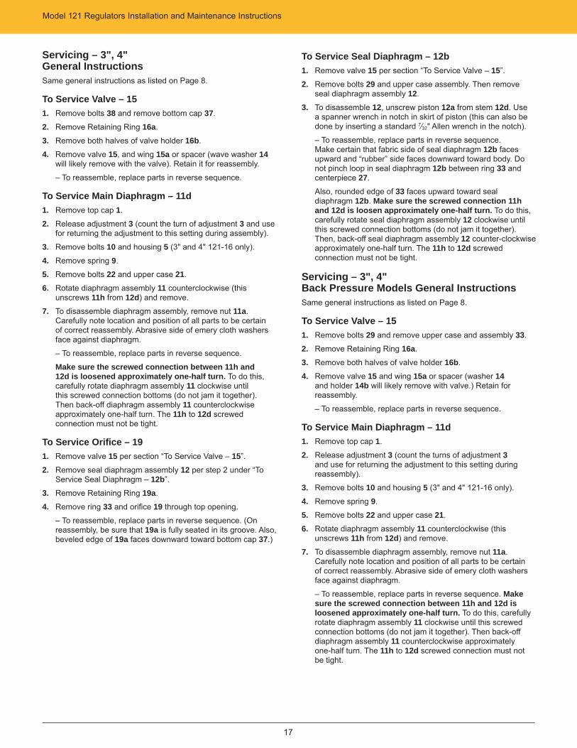
Vacuum Breaker Vacuum Breakers are vacuum limiting devices. In their general function, they can be compared to relief valves or back pressure regulators.
The breaker outlet and control line are piped to the vacuum. The breaker inlet connects to a lesser vacuum, to atmosphere or to a positive pressure. The maximums for the positive pressure are 60 psi for ¾" through 2½" sizes, 40 psi for 3" and 15 psi for 4". The vacuum breaker is normally closed and excess vacuum creates a valve opening movement which increases fl ow from the inlet and thereby relieves or “breaks” the excess.
All of the pipe sizes listed on Page 23 are available ¾" through 4". Note on the cutaway drawing that the main spring is reversed to provide the upward closing force on the valve. Except for certain parts used in the spring assembly, everything else is interchangeable with standard 121 regulators.
Vacuums and Springs
SizeVacuum Range
w.c. vacuum (–w.c.) Spring ColorSpring
Part Number
¾", 1" and 1¼" Model 121-8
3" to 6½" 5" to 8½"8" to 14" 12" to 20" 18" to 30" 30" to 56"
Red-Black Blue-Black
Green-Black Blue (2" O.D.)
Green (2" O.D.) Orange (2" O.D.)
143-82-021-00143-82-021-01143-82-021-02143-16-021-04143-16-021-05143-16-021-06
1½", 2" and 2½"
Model 121-12
3” to 6½"5” to 8½"8" to 14"12" to 28"28" to 56"
Red (2” O.D.)Blue (2” O.D.)
Green (2" O.D.) Orange (2" O.D.)
Black
143-16-021-03 143-16-021-04143-16-021-05143-16-021-06143-16-021-07
3” and 4” Model 121-16
3" to 5½"4" to 7½"7" to 14"
Red (3" O.D.)Blue (3" O.D.)
Green (3" O.D.)
121-62-021-50121-62-021-51121-62-021-52
3" and 4" Model 121-12
12" to 28" 28" to 56"
Orange (2" O.D.) Black
143-16-021-06143-16-021-07
Variations
GIM1328-100
1
3
5
2
4
9
Model 121 Regulators – Variations – Installation and Maintenance Instructions
19
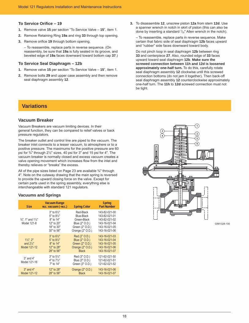
Vacuum RegulatorVacuum Regulators are used to maintain a certain negative pressure (vacuum) in enclosed spaces such as tanks, vessels, chambers, piping systems, etc. In general, these are piped to the regulator inlet and control line connections and the regulator outlet piped to the inlet of a vacuum pump or other vacuum source.
Available pipe sizes are ¾" thru 2½", as listed on Page 23. Note on the cutaway drawing that the spring assembly is arranged for an upward force on the valve. Also, the valve itself is normally open and moves downward to close rather than upward as in the standard 121. With the exception of certain parts involved in the foregoing, everything else is interchangeable with standard 121 regulators.
Vacuums and Springs
SizeVacuum Range
w.c. vacuum (–w.c.) Spring ColorSpring
Part Number
¾", 1" and 1¼"Model 121-8
3" to 6½"5" to 8½"8" to 14"
12" to 20" 18" to 30"
Red-BlackBlue-Black
Green-BlackBlue
Green
143-82-021-00143-82-021-01143-82-021-02143-16-021-04143-16-021-05
1½", 2" and 2½" Model 121-12
3" to 6½"5" to 8½"8" to 14"
RedBlue
Green
143-16-021-03 143-16-021-04143-16-021-05
To Service Vacuum Breaker or Vacuum Regulator1. Remove cover cap 1. Measure depth from top of cover to
ferrule 5 for assembly.
2. Hold Stem 2 from turning using screwdriver on end of stem.
3. Unlock nut 3 from nut 4, then remove nut 3.
4. Slowly remove nut 4 maintaining pressure on spring ferrule 5 to prevent ejection of the spring from the upper case.
Caution: Do not allow stem 2 to unscrew during removal of nut 4.
5. Remove spring 9.
6. To service vacuum breaker, follow procedure for standard regulators by size.
7. To service vacuum regulator, follow procedure for back pressure regulators by size.
GIM1328-105
1
3
5
2
4
9
Model 121 Regulators – Variations – Installation and Maintenance Instructions
20
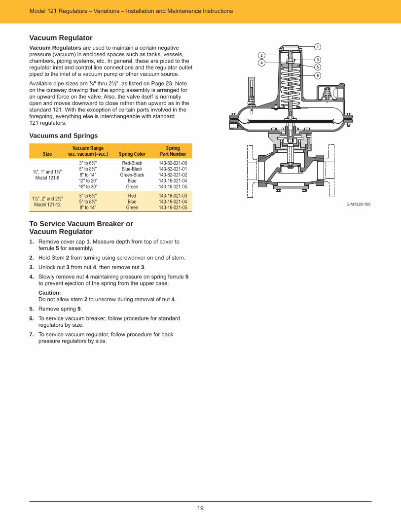
121-RPC (Relay Pilot Control)The 121-RPC is a genuine Pilot Operated Regulator (Relay Principal of Operation).
The relay principal means exceptional precise control. Accuracy is largely unaffected by changes in the inlet pressure.
The control line is piped to both the inlet and main regulator. The loading pressure to the main regulator varies with the downstream pressure resulting in precise regulation. Available in 1½", 2" and 2½" pipe sizes. The outlet pressure ranges from 3½" w.c. through 35 psig. Note on the cutaway drawing that the main spring is reversed to provide the upward closing force.
OutletPressure Range
Pilot SpringSpring Color Spring Part Number
3½" to 6½" w.c. Red 143-08-021-00
5" to 8½" w.c. Blue 143-08-021-01
6" to 14" w.c. Green 143-08-021-02
12" to 28" w.c. Orange 143-08-021-03
1 psig to 2 psig Black 143-08-021-06
1 psig to 5 psig White 138-18-021-01
3 psig to 15 psig Gray 138-18-021-04
10 psig to 35 psig Brown 138-18-021-03
3½" w.c. to 5 psig Aluminum 138-18-021-05
Set-Point AdjustmentThe 121-RPC is factory-adjusted as specifi ed on the order.
To change the set-point:
1. Remove pilot seal cap 10 and loosen lock nut 12.
Caution: Do not remove main cover cap 1. The upper case is sealed and pressurized. The main spring does not contribute to set-point adjustment.
2. Rotate set-point adjustment 11 clockwise to increase or counterclockwise to decrease the outlet pressure.
Caution:a. There should be gas fl ow through the regulator during adjustment, preferably small (approximately 250 SCFH).
b. Do not adjust set point when there is no fl ow.
3. When the desired set-point is achieved, retighten lock-nut 12 and install seal cap 10. Make sure tetraseal 13, is not damaged.
Pilot Spring ChangeThe outlet pressure range of the 121-RPC is determined by the pilot spring (see table of Outlet Pressure Ranges).
To change the spring:
NOTE: Do not change main spring 9. It does not contribute to set-point adjustment.
1. Take regulator out of service per the following section “Shut Down”.
2. Remove pilot seal cap 10, loosen lock nut 12, and turn set-point adjustment 11 counterclockwise until spring compression is released.
3. Remove top cap 14, ferrule 15, and spring 17. Be careful not to lose ball 16.
4. Install new spring. During reassembly make sure the spring is nested correctly at both ends.
5. Adjust to the desired set-point per previous section “Set-Point Adjustment”.
To Service 121-RPC1. Take regulator out of service per section “Shut Down”.
2. Remove cover cap 1. Measure depth from top of cover to ferrule 5 for reassembly.
3. Hold stem 2 from turning using screwdriver on end of stem.
4. Unlock nut 3 from nut 4 and remove nut 3.
5. Slowly remove nut 4 maintaining pressure on the spring ferrule 5 to prevent ejection of the spring from the upper case.
Caution: Do not allow stem 2 to unscrew during removal of nut 4.
6. Remove spring 9.
7. At pilot, disconnect control line which connects to downstream piping.
8. Disconnect pilot supply line between body and pilot regulator.
9. Follow procedures for standard 121 regulators by size.
GIM1328-110
1
3
5
2
4
9
10
14
11
1213
15
1716
Model 121 Regulators – Variations – Installation and Maintenance Instructions
21
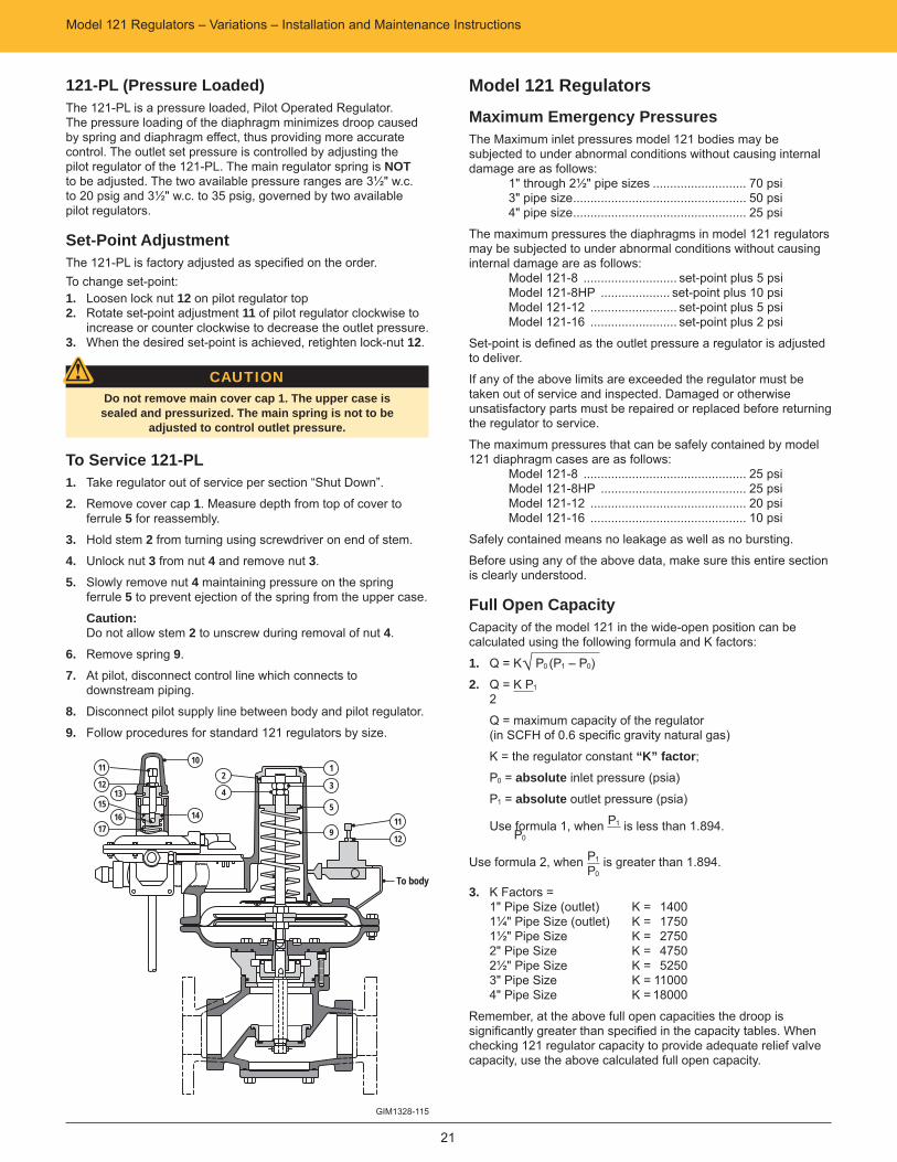
121-PL (Pressure Loaded)The 121-PL is a pressure loaded, Pilot Operated Regulator. The pressure loading of the diaphragm minimizes droop caused by spring and diaphragm effect, thus providing more accurate control. The outlet set pressure is controlled by adjusting the pilot regulator of the 121-PL. The main regulator spring is NOT to be adjusted. The two available pressure ranges are 3½" w.c. to 20 psig and 3½" w.c. to 35 psig, governed by two available pilot regulators.
Set-Point AdjustmentThe 121-PL is factory adjusted as specifi ed on the order. To change set-point:1. Loosen lock nut 12 on pilot regulator top 2. Rotate set-point adjustment 11 of pilot regulator clockwise to increase or counter clockwise to decrease the outlet pressure.3. When the desired set-point is achieved, retighten lock-nut 12.
CAUTIONDo not remove main cover cap 1. The upper case is sealed and pressurized. The main spring is not to be
adjusted to control outlet pressure.
To Service 121-PL1. Take regulator out of service per section “Shut Down”.
2. Remove cover cap 1. Measure depth from top of cover to ferrule 5 for reassembly.
3. Hold stem 2 from turning using screwdriver on end of stem.
4. Unlock nut 3 from nut 4 and remove nut 3.
5. Slowly remove nut 4 maintaining pressure on the spring ferrule 5 to prevent ejection of the spring from the upper case.
Caution: Do not allow stem 2 to unscrew during removal of nut 4.
6. Remove spring 9.
7. At pilot, disconnect control line which connects to downstream piping.
8. Disconnect pilot supply line between body and pilot regulator.
9. Follow procedures for standard 121 regulators by size.
Model 121 Regulators
Maximum Emergency PressuresThe Maximum inlet pressures model 121 bodies may be subjected to under abnormal conditions without causing internal damage are as follows: 1" through 2½" pipe sizes ........................... 70 psi 3" pipe size .................................................. 50 psi 4" pipe size .................................................. 25 psi
The maximum pressures the diaphragms in model 121 regulators may be subjected to under abnormal conditions without causing internal damage are as follows: Model 121-8 ........................... set-point plus 5 psi Model 121-8HP .................... set-point plus 10 psi Model 121-12 ......................... set-point plus 5 psi Model 121-16 ......................... set-point plus 2 psi
Set-point is defi ned as the outlet pressure a regulator is adjusted to deliver.
If any of the above limits are exceeded the regulator must be taken out of service and inspected. Damaged or otherwise unsatisfactory parts must be repaired or replaced before returning the regulator to service.
The maximum pressures that can be safely contained by model 121 diaphragm cases are as follows: Model 121-8 ............................................... 25 psi Model 121-8HP .......................................... 25 psi Model 121-12 ............................................. 20 psi Model 121-16 ............................................. 10 psi
Safely contained means no leakage as well as no bursting.
Before using any of the above data, make sure this entire section is clearly understood.
Full Open CapacityCapacity of the model 121 in the wide-open position can be calculated using the following formula and K factors:
1. Q = K√ P0 (P1 – P0)
2. Q = K P1
2
Q = maximum capacity of the regulator (in SCFH of 0.6 specifi c gravity natural gas)
K = the regulator constant “K” factor; P0 = absolute inlet pressure (psia)
P1 = absolute outlet pressure (psia)
Use formula 1, when P1 is less than 1.894. P0
Use formula 2, when P1 is greater than 1.894. P0
3. K Factors =1" Pipe Size (outlet) K = 14001¼" Pipe Size (outlet) K = 17501½" Pipe Size K = 27502" Pipe Size K = 47502½" Pipe Size K = 52503" Pipe Size K = 110004" Pipe Size K = 18000
Remember, at the above full open capacities the droop is signifi cantly greater than specifi ed in the capacity tables. When checking 121 regulator capacity to provide adequate relief valve capacity, use the above calculated full open capacity.
GIM1328-115
1
3
5
2
4
9
10
14
11
1213
15
1716 11
12
To body
Model 121 Regulators Installation and Maintenance Instructions
22
Over-pressurization ProtectionProtect the downstream piping system and the regulator's low pressure chambers against over-pressurization due to the possible regulator malfunction or failure to achieve complete lockup.
The allowable outlet pressure is the lowest of the maximum pressures permitted by federal codes, state codes, Sensus Bulletin RDS-1498 or other applicable standards. The method of protection can be a relief valve, monitor regulator, shutoff device or similar mechanism.
Materials of Construction
Body and Adapter Cast Iron
Diaphragm Case (8" and 12" Diaphragm) (16" Diaphragm)
Die Cast Aluminum AlloyPermanent Mold Aluminum Alloy
Main and Seal Diaphragms Buna-N or Nylon
Piston for Seal Diaphragm (¾" thru 2½" Model 121) Powdered Iron Zinc PlatedPiston for Seal Diaphragm (3" and 4" Model 121) Aluminum AlloyStem, Stud, Pans and Plates for 8", 12", & 16" Diaphragms Plated Steel
Stem Bushing Stainless Steel
Orifi ce (¾" thru 1¼" Model 121) (1½" thru 4" Model 121)
BrassCast Iron
Retaining Ring (1½" thru 4" Model 121) Plated Steel
Valve Plated Steel with MoldedBuna-N Soft Seal
Valve Wing Plated Steel (3" Model 121)
Valve Holder Plated Steel
Retaining Ring and Wave Washer Stainless Steel
O-rings and Tetraseals Buna-N
Adjustment Spring Ferrule Zinc Die Casting
Bottom Spring Button Powdered Iron-Plated
Adjustment Screw (16" Diaphragm) and H.P. Adjustment Spring Screw Plated Steel
Adjustment Ferrule (16" Diaphragm) and H.P. Adjustment Spring Ferrule Cast Iron
Seal Cap (8" and 12" Diaphragm) (16" Diaphragm)
Zinc Die CastingDie Cast Aluminum Alloy
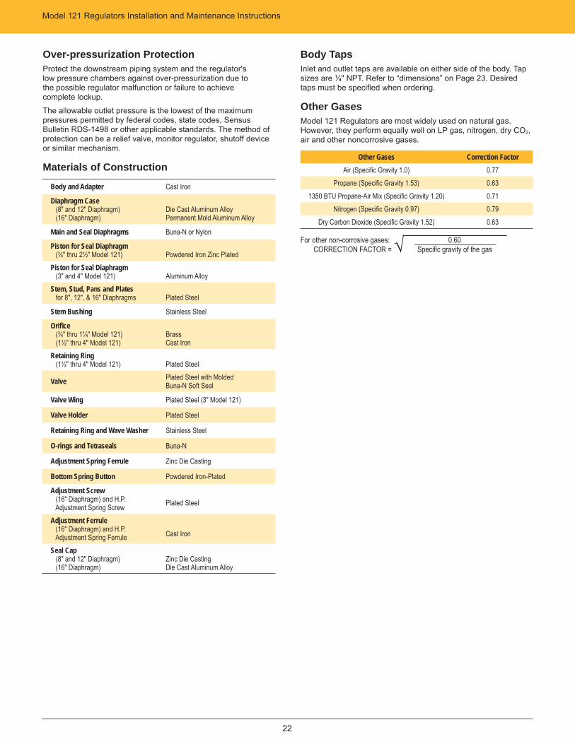
Body TapsInlet and outlet taps are available on either side of the body. Tap sizes are ¼" NPT. Refer to “dimensions” on Page 23. Desired taps must be specifi ed when ordering.
Other GasesModel 121 Regulators are most widely used on natural gas. However, they perform equally well on LP gas, nitrogen, dry CO2, air and other noncorrosive gases.
Other Gases Correction FactorAir (Specifi c Gravity 1.0) 0.77
Propane (Specifi c Gravity 1.53) 0.631350 BTU Propane-Air Mix (Specifi c Gravity 1.20) 0.71
Nitrogen (Specifi c Gravity 0.97) 0.79Dry Carbon Dioxide (Specifi c Gravity 1.52) 0.63
For other non-corrosive gases: 0.60 CORRECTION FACTOR = √ Specifi c gravity of the gas
Model 121 Regulators Installation and Maintenance Instructions
23
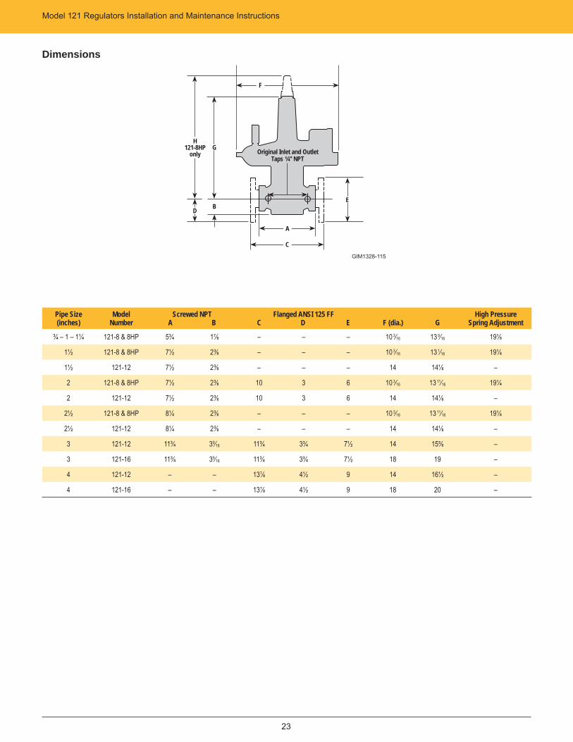
Pipe Size(inches)
Model Number
Screwed NPT A B
Flanged ANSI 125 FF C D E F (dia.) G
High PressureSpring Adjustment
¾ – 1 – 1¼ 121-8 & 8HP 5¾ 1⅞ – – – 10 3⁄16 13 9⁄16 19⅛
1½ 121-8 & 8HP 7½ 2⅜ – – – 10 3⁄16 13 1⁄16 19¼
1½ 121-12 7½ 2⅜ – – – 14 14⅛ –
2 121-8 & 8HP 7½ 2⅜ 10 3 6 10 3⁄16 13 11⁄16 19¼
2 121-12 7½ 2⅜ 10 3 6 14 14⅛ –
2½ 121-8 & 8HP 8¼ 2⅜ – – – 10 3⁄16 13 11⁄16 19¼
2½ 121-12 8¼ 2⅜ – – – 14 14⅛ –
3 121-12 11¾ 39⁄16 11¾ 3¾ 7½ 14 15⅝ –
3 121-16 11¾ 39⁄16 11¾ 3¾ 7½ 18 19 –
4 121-12 – – 13⅞ 4½ 9 14 16½ –
4 121-16 – – 13⅞ 4½ 9 18 20 –
Dimensions
A
C
F
GH
121-8HPonly
D B
Original Inlet and Outlet Taps ¼" NPT
E
GIM1328-115
805 Liberty Boulevard For more information, visit us at www.sensus.com/gasDuBois, PA 158011-800-375-8875
All products purchased and services performed are subject to Sensus terms of sale, available at either: http://na.sensus.com/TC/TermsConditions.pdf or 1-800-METER-IT. Sensus reserves the right to modify these terms and conditions in its own discretion without notice to the customer.
This document is for informational purposes only, and SENSUS MAKES NO EXPRESS WARRANTIES IN THIS DOCUMENT. FURTHERMORE, THERE ARE NO IMPLIED WARRANTIES, INCLUDING WITHOUT LIMITATION, WARRANTIES AS TO FITNESS FOR A PARTICULAR PURPOSE AND MERCHANTABILITY. ANY USE OF THE PRODUCTS NOT SPECIFICALLY PERMITTED HEREIN IS PROHIBITED.
Authorized Distributor:
IN-G-REG-13-28-0312-01-A
Model 121 RegulatorsInstallation and Maintenance Instructions