MobiCom03: Trajectory Based Forwarding and Its Applicationspeters/references/TBF... · Trajectory...
13
Trajectory Based Forwarding and Its Applications Dragos ¸ Niculescu and Badri Nath Rutgers University DATAMAN Lab {dnicules,badri}@cs.rutgers.edu ABSTRACT Trajectory based forwarding (TBF) is a novel method to for- ward packets in a dense ad hoc network that makes it possi- ble to route a packet along a predefined curve. It is a hybrid between source based routing and Cartesian forwarding in that the trajectory is set by the source, but the forwarding decision is based on the relationship to the trajectory rather than names of intermediate nodes. The fundamental aspects of TBF are: it decouples path naming from the actual path; it provides cheap path diversity; it trades off communication for computation. These aspects address the double scalabil- ity issue with respect to mobility rate and network size. In addition, TBF provides a common framework for many ser- vices such as: broadcasting, discovery, unicast, multicast and multipath routing in ad hoc networks. TBF requires that nodes know their position relative to a coordinate sys- tem. While a global coordinate system afforded by a system such as GPS would be ideal, approximate positioning meth- ods provided by other algorithms are also usable. Categories and Subject Descriptors C.2.1 [Network architecture and design]: Wireless com- munication; C.2.2 [Network protocols]: Routing proto- cols Keywords ad hoc networks, trajectory based forwarding, routing, mul- tipath, broadcasting, positioning General Terms Design, Algorithms 1. INTRODUCTION Recent advances in wireless communication devices, sen- sors, hardware (MEMS) technology make it possible to en- vision large scale dense ad-hoc network acting as high reso- lution eyes and ears of the surrounding physical space. Ex- amples of such vision include smartdust [1], dataspaces [2, Permission to make digital or hard copies of all or part of this work for personal or classroom use is granted without fee provided that copies are not made or distributed for profit or commercial advantage and that copies bear this notice and the full citation on the first page. To copy otherwise, to republish, to post on servers or to redistribute to lists, requires prior specific permission and/or a fee. MobiCom’03, September 14–19, 2003, San Diego, California, USA. Copyright 2003 ACM 1-58113-753-2/03/0009 ...$5.00. 3], sensitive skin [4], or disposable networks where it is pos- sible that many of the nodes of the network can be sprayed, dropped, mixed in the material or embedded in the infras- tructure. These networks are characterized by a large number of energy-constrained, unattended nodes. Beside the algorith- mic aspects dictated by their sheer scale, the emphasis on energy efficient algorithms require that nodes often go into doze mode or sleep mode resulting in a very dynamic net- work topology. These characteristics require us to rethink the way many of the networking functions can be imple- mented [5]. One of the fundamental networking functions is routing. Routing always has been treated as sending pack- ets along route paths described by a discrete set of points. Routing algorithms used in the fixed networks and those proposed by the MANET community for ad-hoc networks are aimed at resource-rich, relatively stable networks. In this paper, we propose a new forwarding paradigm, Trajectory based forwarding (TBF) which addresses the is- sue of scalability and dynamic network topology. This is fundamentally new approach to routing in “dense matter” where the route path is specified and treated as a continuous function as opposed to a discrete set of points. The transi- tion from a discrete view of route paths to a continu- ous view of route paths is only natural as we move from dealing with sparse networks to dealing with dense networks. The key idea in the approach is to embed a trajectory in the packet and then let the intermediate nodes forward packets to those nodes that lie more or less on the trajectory. Rep- resenting route paths as trajectories is an efficient scalable encoding technique for dense networks. Since a trajectory does not explicitly encode the nodes in the path, it is to a large extent impervious to changes in specific nodes that make up the topology. We believe that trajectories are a natural namespace to describe route paths when the topol- ogy of the network matches the topography of the physical surroundings in which it is deployed which by very defini- tion is embedded computing. Here, the physical paths tra- versed by packets mirror the underlying shape of the phys- ical space that is being queried. Further, forwarding pack- ets along trajectories can be very effective in implementing many networking functions when standard bootstrapping or configuration services are not available, as will be the case in disposable networks where nodes are thrown or dropped to form a one-time use network. Although Cartesian routing [6] offers the possibility of routing packets based on positions, it does so only on straight lines between source and destination. There are many prac- 260
Transcript of MobiCom03: Trajectory Based Forwarding and Its Applicationspeters/references/TBF... · Trajectory...
Trajectory Based Forwarding and Its Applications
Dragos Niculescu and Badri NathRutgers University
DATAMAN Lab
{dnicules,badri}@cs.rutgers.edu
ABSTRACTTrajectory based forwarding (TBF) is a novel method to for-ward packets in a dense ad hoc network that makes it possi-ble to route a packet along a predefined curve. It is a hybridbetween source based routing and Cartesian forwarding inthat the trajectory is set by the source, but the forwardingdecision is based on the relationship to the trajectory ratherthan names of intermediate nodes. The fundamental aspectsof TBF are: it decouples path naming from the actual path;it provides cheap path diversity; it trades off communicationfor computation. These aspects address the double scalabil-ity issue with respect to mobility rate and network size. Inaddition, TBF provides a common framework for many ser-vices such as: broadcasting, discovery, unicast, multicastand multipath routing in ad hoc networks. TBF requiresthat nodes know their position relative to a coordinate sys-tem. While a global coordinate system afforded by a systemsuch as GPS would be ideal, approximate positioning meth-ods provided by other algorithms are also usable.
Categories and Subject DescriptorsC.2.1 [Network architecture and design]: Wireless com-munication; C.2.2 [Network protocols]: Routing proto-cols
Keywordsad hoc networks, trajectory based forwarding, routing, mul-tipath, broadcasting, positioning
General TermsDesign, Algorithms
1. INTRODUCTIONRecent advances in wireless communication devices, sen-
sors, hardware (MEMS) technology make it possible to en-vision large scale dense ad-hoc network acting as high reso-lution eyes and ears of the surrounding physical space. Ex-amples of such vision include smartdust [1], dataspaces [2,
Permission to make digital or hard copies of all or part of this work forpersonal or classroom use is granted without fee provided that copies arenot made or distributed for profit or commercial advantage and that copiesbear this notice and the full citation on the first page. To copy otherwise, torepublish, to post on servers or to redistribute to lists, requires prior specificpermission and/or a fee.MobiCom’03, September 14–19, 2003, San Diego, California, USA.Copyright 2003 ACM 1-58113-753-2/03/0009 ...$5.00.
3], sensitive skin [4], or disposable networks where it is pos-sible that many of the nodes of the network can be sprayed,dropped, mixed in the material or embedded in the infras-tructure.
These networks are characterized by a large number ofenergy-constrained, unattended nodes. Beside the algorith-mic aspects dictated by their sheer scale, the emphasis onenergy efficient algorithms require that nodes often go intodoze mode or sleep mode resulting in a very dynamic net-work topology. These characteristics require us to rethinkthe way many of the networking functions can be imple-mented [5]. One of the fundamental networking functions isrouting. Routing always has been treated as sending pack-ets along route paths described by a discrete set of points.Routing algorithms used in the fixed networks and thoseproposed by the MANET community for ad-hoc networksare aimed at resource-rich, relatively stable networks.
In this paper, we propose a new forwarding paradigm,Trajectory based forwarding (TBF) which addresses the is-sue of scalability and dynamic network topology. This isfundamentally new approach to routing in “dense matter”where the route path is specified and treated as a continuousfunction as opposed to a discrete set of points. The transi-tion from a discrete view of route paths to a continu-ous view of route paths is only natural as we move fromdealing with sparse networks to dealing with dense networks.The key idea in the approach is to embed a trajectory in thepacket and then let the intermediate nodes forward packetsto those nodes that lie more or less on the trajectory. Rep-resenting route paths as trajectories is an efficient scalableencoding technique for dense networks. Since a trajectorydoes not explicitly encode the nodes in the path, it is toa large extent impervious to changes in specific nodes thatmake up the topology. We believe that trajectories are anatural namespace to describe route paths when the topol-ogy of the network matches the topography of the physicalsurroundings in which it is deployed which by very defini-tion is embedded computing. Here, the physical paths tra-versed by packets mirror the underlying shape of the phys-ical space that is being queried. Further, forwarding pack-ets along trajectories can be very effective in implementingmany networking functions when standard bootstrapping orconfiguration services are not available, as will be the casein disposable networks where nodes are thrown or droppedto form a one-time use network.
Although Cartesian routing [6] offers the possibility ofrouting packets based on positions, it does so only on straightlines between source and destination. There are many prac-
260

tical network services that require routing along routes pos-sibly other than the shortest path. One such example ismultipath routing, which may be employed by a source toincrease bandwidth, or resilience of communication. Rout-ing along the shortest path is not always the best optionin wired networks [7]. In sensor networks the same prob-lem manifests itself as potential network partitioning due tobattery overuse along popular shortest paths. Communica-tion over alternate paths must be therefore used as a loadbalancing method in order to achieve more uniform batterydepletion. Finally, non straight trajectories are necessaryto describe unicast routes in a network where straight lineforwarding is not possible due to obstacles, holes in connec-tivity, or other criteria, such as security requirements.
TBF has a number of features that make it an ideal can-didate for a low level primitive in any ad hoc network.
1. it decouples the the path name from the path itself.This is the most critical aspect in a dense network,where intermediate nodes between source and destina-tion might move, go into doze mode or fail, therebyrendering a discrete source based path useless.
2. the specification of the trajectory is independent of thename of the destination. This makes TBF usable as arouting support, when the destination is indicated, asa discovery support primitive, when the destination isnot known, or as a flooding replacement.
3. it provides cheap path diversity, when compared toflooding based traditional methods of finding alternatepaths.
4. it trades off communication for computation, by declar-ing paths instead of searching them. This is a desirabletradeoff, considering the four orders of magnitude dif-ference between the cost of sending a wireless packetand executing an instruction [1].
5. it may be assisted by various functionalities availablein the nodes. Ideally, each node would be equippedwith a GPS receiver, case in which nodes closest to theindicated trajectory will forward the packet. If, how-ever, GPS is not available (such as non line of sightscenarios, or lack of sufficient precision) TBF may useapproximate positions given by positioning algorithms[8, 9, 10, 11] that are based on nodes’ other abilities tosense their neighbors (ranging, angle of arrival, com-pass).
Besides simple unicast, trajectory routing and forwardinghave significant advantages for many other important net-work functions such as broadcasting, discovery, multipath,multicast and broadcast, path resilience. In this paper, wefocus on issues related to trajectory forwarding in networkswith and without the availability of node positions, andidentify a number of research challenges related to trajec-tories in ad hoc networks.
The rest of the paper is organized as follows: the nextsection reviews related work, section 3 details our proposedapproach, the network model assumptions, various forward-ing methods and implementation issues; section 4 reviewsapplications that benefit from an implementation under theTBF framework; section 5 debates problems TBF faces un-der adverse conditions such as reduced density and lack of
positioning capabilities. Section 6 summarizes the currentstatus of the project and mentions some challenging issuesand possible future work, and we summarize with some con-cluding remarks in section 7.
2. RELATED WORKThere have been significant efforts to improve routing in
both fixed and mobile networks when position is available.Such methods, in which node spatial positions are essentialto the method, are branded “position centric”. Geographicrouting [12] is a hierarchical scheme where each router is re-sponsible for a polygonal region possibly subpartitioned intodisjoint polygons assigned to other routers. This routingscheme provides an infrastructure that can be embedded inIP, and can deliver messages to specific geographic regions.Cartesian routing [6] is a greedy method that chooses a nexthop that provides most progress towards the destination. Itis a particular case of TBF, and both are representativefor position centric routing. LAR (Location Aided Routing)[13] is another (position centric) scheme that implements re-stricted area flooding in order to reduce the cost of discoverywhen the uncertainty about a destination is limited. It usesa phase of source based routing and a phase of controlledflooding.
Cartesian routing, and other greedy methods derived fromit do not guarantee the delivery of the packets. The problemis usually addressed by planarizing the network graph andapplying detour algorithms, such as FACE [14], GPSR [15],or GOAFR+ [16], that avoid obstacles using the “right handrule” strategy that work well for straight line delivery.
The other big category, inherited from wired networks,is “node centric” - destinations and intermediate forwardingentities are names of nodes. DSR (Dynamic Source Routing)[17] is a form of source based routing used in MANET [18],featuring a route discovery phase based on flooding, androutes completely specified in packet headers. Terminoderouting [19] is also a source based method, but uses anchorsinstead of intermediate nodes. It is close in spirit to ourproposed method, but is discrete in the representation ofthe path. The method may still entail large overheads forlong paths that might otherwise have a compact parametricrepresentation.
In order to use position centric approaches, node posi-tions are necessary, but a locations service is also necessaryto translate node addresses into coordinates. GLS (Grid Lo-cation Service) [20] implements a naming service that allowsnode centric applications to run on top of geographic andcartesian routing. A source can find the coordinates of thedestination node from the location service and then use ge-ographic or cartesian routing to route to that destination.Other location services include DREAM [21], which updateslocations with remote communication pairs based on angu-lar drift, and [22], which makes use of Bloom filters to decideif a mobile is in a certain area.
A more recent approach is “data centric”, pioneered in[5], in which routing is driven by interests, describing themeaning of data transfered. In a sensor network, multipathrouting may be useful in providing resilience [23].
TBF can be used to enhance or complement all the nodecentric, position centric and data centric mechanisms, or toreplace expensive energy-wise parts of them, such as floodingbased discovery.
261

Figure 1: TBF layer
(LPS)
FloodingMultipath
(APS)GPS
Ad hocroutingrouting
Positioning Algo
Trajectory Based Forwarding
No position
Discovery
3. TBF DESCRIPTIONTBF is a hybrid technique combining source based rout-
ing [17] and Cartesian forwarding [6], but uses a continuousrepresentation of the route. Like in source based routing,the path is indicated by the source, but without actuallyspecifying all the intermediate nodes. Like in Cartesian for-warding, decisions taken at each node are greedy, but arenot based on distance to destination - the measure is thedistance to the desired trajectory. Source based routinghas the advantage that intermediate nodes are relieved ofusing and maintaining large forwarding tables, but it hasthe disadvantage of the packet overhead increasing with thepath length. Cartesian routing uses positions to get rid ofthe routing tables, but defines one single forwarding policy:greedy, along a straight line.
TBF gets the best of the two methods: packets followa trajectory established at the source, but each forwardingnode takes a greedy decision to infer the next hop basedon local position information, while the overhead of repre-senting the trajectory does not depend on path length. In anetwork where node positions are known, the packet may beforwarded to the neighbor that is geographically closest tothe desired trajectory indicated by the source node. If thedestination node is known, the trajectory followed by thepacket might be a line, and the method reduces to carte-sian forwarding. In the general case, however, we envisiona larger array of applications including ad hoc routing, dis-covery, flooding, and multipath routing, as shown in figure1. Trajectory based forwarding (TBF) requires that nodesbe positioned relative to a global coordinate system or a rel-ative coordinate system. The strength of TBF lies in theflexibility of being able to work over a wide variety of po-sitioning systems. In fact, TBF can be seen as a middlelayer between global [24], ad hoc [8, 25, 9, 10] and local [11]position providing services, and many network managementservices.
3.1 Forwarding methodsIn the TBF framework, routing a packet requires that
a trajectory be specified along which a packet can be for-warded. The trajectory is usually decided by the sourceand we will assume that it is expressed in parametric formX(t), Y (t). For example, to route along a line with slope αpassing through the source with coordinates x1, y1, the tra-jectory would be described by X(t) = x1 + t cos(α); Y (t) =y1 + t sin(α). α, x1, y1 are constants, and the parametert actually describes euclidean distance traveled along theline. It is convenient, for the simplicity of the explanation
Figure 2: Forwarding on a curve
dt
X(t),Y(t)
N0
Neighborhood of N0
N1
N2
N3
N4
t0t0− 2dt
t0 + 3dt
t0+ 5dt
t 0+
8dt
to assume that t indicates the distance on the curve, butit need not be so in the general case. The neighborhood ofa node N0 (figure 2) is defined as the portion of the curveand the nodes that are within a certain distance form N0,shown by a dashed line in the figure. In the simplest case,the neighborhood could be the smallest circle enclosing allN0’s one hop neighbors. In a network in which node posi-tions are known, the main question is how to choose a nexthop that best approximates the trajectory. Assume nodeN0 receives a packet with the trajectory indicated by thecurve X(t), Y (t) and the value t0 that corresponds to thepoint on the curve that is closest to N0. Using samplingof the curve at dt spaced intervals, indicated by dots in thedashed trajectory curve, N0 can compute all the points ofthe curve that reside inside its neighborhood. For all neigh-bors N1..N4, their corresponding closest points on the curveare t0, t0+3dt, t0+5dt, t0+8dt. When referring to curve fit-ting, these values are called residuals. In fact, the mentionedmethod computes an estimation of the residuals, instead ofthe true ones, which would require either infinite resolution(dt → 0), or usage of higher derivatives of X(t) and Y (t).Since choosing a next hop for the packet should be towardsadvancement on the trajectory, only the portion of the curvewith t > t0 is considered. For this reason, node N1 receivest0 as the closest point, instead of t0 − 2dt, which would becloser to the perpendicular from N1 onto the curve. Severalpolicies of choosing a next hop are possible:
• “minimum deviation”: choose the node closest to thecurve, with the minimum residual. This policy wouldfavor node N2 and would tend to produce a lower de-viation from the ideal trajectory;
• most forwarding within radius (MFR) [26], choosingN4. This policy should also be controlled by a thresh-old of a maximum acceptable residual, in order to limitthe drifting of the achieved trajectory. It would pro-duce paths with fewer hops than the previous policy,but with higher deviation from the ideal trajectory;
• centroid of the feasible set, favoring N3: the centroid isa way to uniformly designate clusters along the trajec-tory, and a quick way to determine the state of highlydense networks;
• the node with most battery left;
262

• randomly choose between best three: useful when nodepositions are imperfect, or when it may be necessaryto route around obstacles;
• in mobile networks a forwarding policy that might pro-vide better results would be to choose the next hopwhich promises to advance along the trajectory, or onethat is expected to have the least mobility in the fu-ture.
3.2 Trajectory specification/encodingThere are a number of choices in representing a trajectory:
functional, equational, or parametric representation. Func-tional representation (e.g. Y = f(X)) cannot be used tospecify all types of curves (for example vertical lines). Equa-tional representation (e.g. X2 + Y 2 = R2) requires explicitsolution to determine the points on the curve. Parametricrepresentation (e.g. X = X(t), Y = Y (t)) is ideally suitedfor the purpose of forwarding. The parameter t of the curveis a natural metric to measure the forward progress alongthe path and can be linked to either length traveled on thecurve, or hop count.
The next issue is how to encode a trajectory that can haveseveral parameters which have to be interpreted by nodes.One approach is to have a tabular representation where thenodes know how to interpret the fields given a well knowset of trajectories. The line mentioned in subsection 3.1would be represented by a tuple (line, x1, y1, α), possiblywith additional bits describing the forwarding policy. Thefirst item describes the type of trajectory, followed by thespecific parameters. A node would have a fixed dictionaryof available trajectories – this method provides the lowestpacket overhead, but limited flexibility.
Complex trajectories can have multiple components or agiven trajectory can be specified as a number of simple com-ponent such as Fourier components. The more Fourier com-ponents are specified in the packet, the better the accuracyof the trajectory is. There is an interesting tradeoff betweenthe accuracy of the curve and the overhead of specifyingthe components and interpreting them. Other possibilitiesof encoding of the parametric curve include compiled form(ready to be executed, as in active networking), or reversepolish notation (ready to be interpreted). In our currentimplementation on Mica motes, we used the latter, for theincreased flexibility.
For multicast, a source based method like TBF shouldstore the entire distribution tree in each packet, which couldsignificantly increase overhead. However, in certain casesthis overhead may be reduced. When the tree has a regu-lar shape, like a self repeating structure, its recursive rep-resentation is actually very compact. In figure 3, line ABis defined in its parametric form, but parameterizing whatwe previously used as constants: x1 := xA; y1 := yA andα := αA, with an additional parameter tmax to indicatethe packet duplication point B. Therefore, the descriptionof segment AB is:
XAB(t) = xA + t cos(αA)YAB(t) = yA + t sin(αA)
When t ∈ (0, tmax), forwarding works using normal uni-cast in the interval AB. A node that is close to B, with thecoordinates B(XAB(tmax), YAB(tmax)), performs the dupli-cation task required in multicast, and prepares two new tra-
Figure 3: Regular tree representation
CD
A
B
x1 := xA; y1 := yA; α := αA
XAB(t) = xA + t sin αA
YAB(t) = yA + t cos αA
x1 := XAB(tmax)
y1 := YAB(tmax)
α:=
α+
π3
α:=
α−
π3
jectories. These are BC and BD, in fact lines of lengthtmax, just like their parent, but with different parameters. tstarts fresh from 0, for both these two segments, and staysin the same interval t ∈ (0, tmax), but with new equations:
XBC(t) = xB + t cos(αA + π3)
YBC(t) = yB + t sin(αA + π3)
XBD(t) = xB + t cos(αA − π3)
YBD(t) = yB + t sin(αA − π3)
Their starting point is B, the ending point of the par-ent, with coordinates xB = XAB(tmax), yB = YAB(tmax),and their angles diverge in this example by 2π
3from each
other, being π3
sideways of their parent. The node respon-sible for duplication at point B receives a TBF packet withthe tuple (line, xA, yA, αA, tmax), which describes XAB(t)and YAB(t), and creates two new TBF packets described bytuples:
• (line, XAB(tmax), YAB(tmax), αA + π3, tmax)
• (line, XAB(tmax), YAB(tmax), αA − π3, tmax)
The packet splits behave like recursive calls in the compactrepresentation of this fractal structure, meaning that thesplitting process will continue at points C and D. The rep-resentation is compact in that for describing an arbitrarilylarge tree of this shape, just the three tuples mentioned needbe transmitted as trajectory encoding. The structure pro-duced by this particular example is in fact a honeycombstructure, shown in figure 8b. The recursive definition ofthe structure will eventually overlap itself, therefore mark-ing bits are necessary in order to stop the forwarding. Thisis also discussed in the context of stateful versus statelessbroadcasting (section 4.5).
Even in the case of an arbitrary tree the overhead may bereduced by a simple pruning scheme. This is the case whenthe tree must be described in its entirety at the source, forexample by specifying the splitting points. In figure 4, thetree describing the leafs (multicast receivers) and the split-ting points gets stripped as the forwarding proceeds down-stream. The amount of total overhead as a function of n,
263

Figure 4: Arbitrary tree pruning
Figure 5: Examples of trajectory routing and for-warding
D
D D
D
S
(1)
(2)
(3)
(b)
(5)
D
N
D
D D
D
(4)
(c) (d)(a)
SS
DD
(e) (f)
SS
S
the total number of receivers, is therefore O(n log n) in theaverage case (for balanced trees), as opposed to O(n2) whensending the full tree on each branch.
4. APPLICATIONS OF TBFHaving discussed the implementation details of TBF, we
shall now investigate some of the applications that wouldbenefit from an implementation under the TBF framework.There is a wide variety of trajectory shapes that can be usedin applications, but a broad classification of trajectories maybe into simple or composed. Simple trajectories describe asingle continuous curve, and, in the context of routing, areused for unicast. Composed trajectories describe several,spatially different curves. They may also be used for unicastin an anchor based fashion, when a complicated trajectory isdescribed as a list of simpler trajectories. Composed trajec-tories have a more obvious use in broadcast and multicast,where a unique curve is less appropriate.
A sampling of TBF based applications is shown in fig-ure 5. A naive broadcasting scheme based on trajectories
Figure 6: Discovery example
125
126
127
128
129
130
131
132
133
134
135
136
137
138
139
140
141
142
143
144
145
146
147148
149150
151
152
153
154
155
156
157
158
159
160
161
162
163
164
165
166
167
168
169
170
171
172
173
174
175
176
177
178
179 180
181
182
183
184
185
186
187
188
189
190
191
192
193
194
195
196
197
198
199
0
1
2
3
4
5
6
7
8
9
10
11
12
13 14
15
16
17
18
19
20
21
22
23
24
25
26
27
28
29
30
31
32
33
34
35
36
37
38
39
40
41
42
43
44
45
46
47
48
49
50
5152
53
54
55
56
57
58
59
60
61
62
63
64
65
66
67
68
69
70
71
72
73
74 75
76
77
78
79
80
81
82
83
84
85
86
87
88
89
90
91
92
93
94
95
96
97
98
99100
101
102
103
104
105
106
107
108
109
110
111
112
113
114
115 116
117
119
120
121
122
123
124
118
I
CS
uses a number of radial outgoing lines that are reasonablyclose to each other to achieve a similar effect without all thecommunication overhead involved by receiving duplicatesin classical flooding (figure 5a). More generally, a sourcewould indicate the directions and the lengths of the linesthat would achieve a satisfactory coverage (figure 5e). Cov-erage relies on the typical broadcast property of the wirelessmedium, in which several nodes overhear the packet beingforwarded. Recovery from failure often involves multipathrouting from a source to a destination. In a sensor network,both disjoint (figure 5b) and braided (figure 5c) paths areuseful in providing resilience [23]. A simple five step dis-covery scheme (figure 5d) based on linear trajectories maybe used to replace traditional broadcast based discovery. Ifunicast communication is modeled by a simple curve, mul-ticast is modeled by a tree in which each portion might bea curve, or a simple line. Distribution trees are used foreither broadcasting (figure 5e), or multicast routing (figure5f). A source knowing the area to be flooded can generate atree describing all the lines to be followed by packets in or-der to achieve complete distribution with minimal broadcastcommunication overlap. A multicast source knowing posi-tions for all members of a group may generate a spanningtree built of linear trajectories to be followed by packets.There is an overhead to be paid in describing the tree ineach packet, but the solution saves in route maintenance.
4.1 Unicast routingThe prime application of forwarding is routing. The dif-
ference between the two is that in forwarding, a trajectoryneed not have a particular destination. Routing involves notonly delivery to the destination, but the entire process thatsupports the delivery. This includes forwarding, and alsobuilding or updating routing tables. In order to route, theposition of a given destination node is needed, as providedby a location service [20, 22], to enable node centric applica-tions run on top of position centric routing. The other cen-tral problem is how to determine the actual trajectory. Sofar we experimented with simple trajectories, such as linesand sine waves, but the more general question is how to de-termine the trajectory when the position of the destinationis known. If the topology is uniform in terms of density andcapacity, it is likely that simple lines and parabolas for alter-
264

Figure 7: Naive TBF based broadcasting
75
76
77
78
79
80
81
82
83
84
85
86
87
88
89
90
91
92
93
94
95
96
97
98
99100
101
102
103
104
105
106
107
108
109
110
111
112
113
114
115 116
117
118
119
120
121
122
123
124
125
126
127
128
129
130
131
132
133
134
135
136
137
138
139
140
141
142
143
144
145
146
147148
149150
151
152
153
154
155
156
157
158
159
160
161
162
163
164
165
166
167
168
169
170
171
172
173
174
175
176
177
178
179 180
181
182
183
184
185
186
187
188
189
190
191
192
193
194
195
196
197
198
199
0
1
2
3
4
5
6
7
8
9
10
11
12
13 14
15
16
17
18
19
20
21
22
23
24
25
26
27
28
29
30
31
32
33
34
35
36
37
38
39
40
41
42
43
44
45
46
47
48
49
50
5152
53
54
55
56
57
58
59
60
61
62
63
64
65
66
67
68
69
70
71
72
73
74
0
20
40
60
80
100
4 5 6 7 8 9 10 11 12
Com
mun
icat
ion
/ Cov
erag
e [%
]
Number of radial directions
CoverageCommunication as a fraction of flooding
nate paths would suffice. If the network exhibits more vari-ation, in general shape of policy defined islands (of security,or capabilities for example), determination of the trajectorycannot be done with localized decisions. For these cases, weintend to explore the creation of a service responsible fortrajectory mapping, that would take into consideration allthe aspects in the creation of routes.
4.2 Multipath routingMore advantages are brought by TBF for multipath rout-
ing, which may be employed by a source to increase band-width or resilience of communication. The key feature hereis the cheap path diversity. Using TBF, the source maygenerate either disjoint paths as disjoint curves, or braidedpaths as two intersecting sine waves. In networks with lowduty cycles, such as sensor networks, longer alternate pathsmight actually be more desirable in order to increase theresilience of the transmitted messages (concept similar toFourier decomposition), or to distribute the load onto thebatteries. Since there is essentially no route maintenance,each packet can take a different trajectory, depending onits resilience requirements (similar to different FEC require-ments). The multiple paths between a source and a desti-nation can therefore be alternated to cheaply achieve loadbalancing.
4.3 MobilityMobile networks are a case in which TBF provides a de-
sirable solution due to its decoupling of path name fromthe path itself. In a mobile ad hoc network, route main-tenance for trajectory based routing comes for free since allthat is needed is the position of the destination. This is es-pecially true when only the intermediate nodes or the sourceare moving, and the destination of the packet remains fixed.When the destination is moving, a location service [20] maybe used, or the source may quantify its uncertainty aboutthe destination by using a localized flooding around the des-tination (figure 5e).
4.4 DiscoveryOne of the areas in which TBF is particularly appropriate
is quick and dirty implementation of services with-out the support of preset infrastructure. Such is the caseof discovery - of topology, or of some resource. Many al-gorithms use initial discovery phases based on flooding [17,
5] in order to find a resource or a destination. Generaliz-ing an idea presented in [27], a replacement scheme usingtrajectories is as follows: possible destinations (servers S)advertise their position along arbitrary lines and clients Cwill replace their flooding phase with a query along anotherarbitrary line which will eventually intersect the desired des-tination’s line. The intersection node then notifies the clientabout the angle correction needed to contact the server di-rectly (figures 5d and 6). In order to guarantee that theserver and client lines intersect inside the circle with diam-eter CS, it is in fact necessary for the nodes each to send infour cardinal directions.
4.5 BroadcastingBroadcasting is one of the most used primitives in any
network, used for tasks ranging from route discovery at thenetwork layer, to querying and resource discovery at the ap-plication layer. Its most frequent implementation is underthe form of suppressed flooding, which entails each node ofthe network broadcasting the message exactly once. It is astateful method, since it requires bits to mark the statusof a node - covered or uncovered. The problem with themarking bits is that they have to be provisioned on a perbroadcast basis, if several broadcasts are to be supportedsimultaneously. If only O(1) marking bits are used, someglobal serialization is necessary. For example if one bit isused, one broadcast is supported in the network, and afterthe settling time (time at which last copy of a message isbroadcast), the bit has to be cleared to allow for anotherbroadcast. Suppressed flooding also incurs several otherproblems: increased communication [28], increased settling,time poor scalability and delivery ratio in congested net-works [29]. Probabilistic flooding [30] addresses some ofthese problems by flipping a coin each time a node has torebroadcast the message. This reduces the number of du-plicates a node receives, but the method exhibits a bimodalbehavior, meaning that either the broadcast is successful incovering most of the network, or it dies very early, coveringonly a small portion around the source. While broadcastingis not the main application of TBF, we can provide solutionsthat address most shortcoming of traditional flooding and ofprobabilistic flooding. The broadcast achieved by TBF alsohas an approximate nature, just like probabilistic flooding,meaning that there may be nodes which do not receive themessage even under ideal collision free conditions.
265
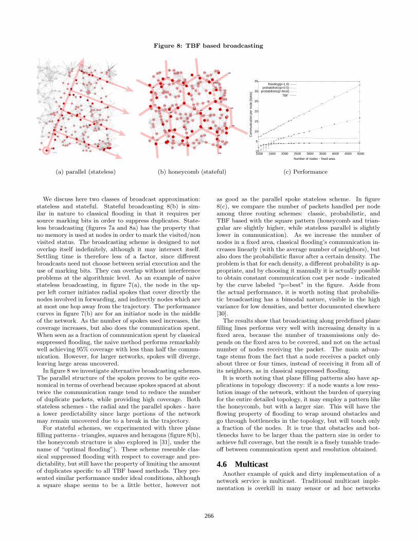
Figure 8: TBF based broadcasting
330
335
337
339 351
353
356
364
366
368
372
377
385
386
393
394
397
399
401
406
407
410
412
430
432
434
435
444
451 459
460
462
467
470
472
476
482
484
490
498
500
509
513
515
516
519
522
523
524
527
528
534
535
541
542
544
545
564
579581
592
600
606
610
613
615
623
625
632
636
640
643
647
648
650
652
654
655
664
670
671
674
683
689693
698
700
701
720
722
724
726
733
738
740
741
745
750
760
763
765 772
779
788
790
795
804
806
809
810
811
812
821
824
832
843
850
851
853
854
873
878 880
883
890
894
895
896
897
899
901
905
906
912
926
929
938
940
944
945
955
959
962
963
965
968
970
977
986s654s654
s51s51
s944s944
s393s393
F<−1100.00
2
7
11
20
22
23
32
33
34
37
39
42
49
51
52
54
55
56
59
64
65
66
71
72
7989
92
94
95
97
98
111
112
113
117
119
124
129
137
145
147
156
158
159
162
163
168
169
175
179
184
203
206
213
214
219
224
226
231
232
240
244
245
246
247
248
253
254
258
265
274
276
278
280
291
292
295
296
297
304
305
307
310
317
319
(a) parallel (stateless)
185
186
187
188
189
190
191
192
193
194
195
196
197
198
199
s169s169
s166s166
s107s107
s139s139
s155s155
s42s42
s124s124
s106s106
F<−2250.00
s191s191
s183s183
s167s167
s178s178
s177s177
s54s54
s135s135
s15s15
s187s187
s110s110
0
1
2
3
4
5
6
7
8
9
10
11
12
13 14
15
16
17
18
19
20
21
22
23
24
25
26
27
28
29
30
31
32
33
34
35
36
37
38
39
40
41
42
43
44
45
46
47
48
49
50
5152
53
54
55
56
57
58
59
60
61
62
63
64
65
66
67
68
69
70
71
72
73
74 75
76
77
78
79
80
81
82
83
84
85
86
87
88
89
90
91
92
93
94
95
96
97
98
99100
101
102
103
104
105
106
107
108
109
110
111
112
113
114
115 116
117
118
119
120
121
122
123
124
125
126
127
128
129
130
131
132
133
134
135
136
137
138
139
140
141
142
143
144
145
146
147148
149150
151
152
153
154
155
156
157
158
159
160
161
162
163
164
165
166
167
168
169
170
171
172
173
174
175
176
177
178
179 180
181
182
183
184
(b) honeycomb (stateful)
0
5
10
15
20
25
30
35
1000 1500 2000 2500 3000 3500 4000 4500 5000
Com
mun
icat
ion
per
node
[#pk
ts]
Number of nodes − fixed area
flooding(p=1.0)probabilistic(p=0.5)
probabilistic(p=best)TBF
(c) Performance
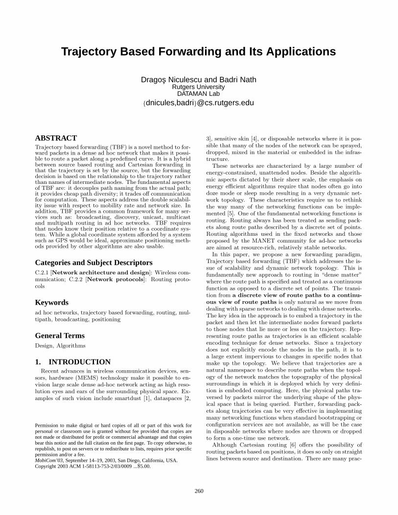
We discuss here two classes of broadcast approximation:stateless and stateful. Stateful broadcasting 8(b) is sim-ilar in nature to classical flooding in that it requires persource marking bits in order to suppress duplicates. State-less broadcasting (figures 7a and 8a) has the property thatno memory is used at nodes in order to mark the visited/nonvisited status. The broadcasting scheme is designed to notoverlap itself indefinitely, although it may intersect itself.Settling time is therefore less of a factor, since differentbroadcasts need not choose between serial execution and theuse of marking bits. They can overlap without interferenceproblems at the algorithmic level. As an example of naivestateless broadcasting, in figure 7(a), the node in the up-per left corner initiates radial spokes that cover directly thenodes involved in forwarding, and indirectly nodes which areat most one hop away from the trajectory. The performancecurves in figure 7(b) are for an initiator node in the middleof the network. As the number of spokes used increases, thecoverage increases, but also does the communication spent.When seen as a fraction of communication spent by classicalsuppressed flooding, the naive method performs remarkablywell achieving 95% coverage with less than half the commu-nication. However, for larger networks, spokes will diverge,leaving large areas uncovered.
In figure 8 we investigate alternative broadcasting schemes.The parallel structure of the spokes proves to be quite eco-nomical in terms of overhead because spokes spaced at abouttwice the communication range tend to reduce the numberof duplicate packets, while providing high coverage. Bothstateless schemes - the radial and the parallel spokes - havea lower predictability since large portions of the networkmay remain uncovered due to a break in the trajectory.
For stateful schemes, we experimented with three planefilling patterns - triangles, squares and hexagons (figure 8(b),the honeycomb structure is also explored in [31], under thename of “optimal flooding”). These scheme resemble clas-sical suppressed flooding with respect to coverage and pre-dictability, but still have the property of limiting the amountof duplicates specific to all TBF based methods. They pre-sented similar performance under ideal conditions, althougha square shape seems to be a little better, however not
as good as the parallel spoke stateless scheme. In figure8(c), we compare the number of packets handled per nodeamong three routing schemes: classic, probabilistic, andTBF based with the square pattern (honeycomb and trian-gular are slightly higher, while stateless parallel is slightlylower in communication). As we increase the number ofnodes in a fixed area, classical flooding’s communication in-creases linearly (with the average number of neighbors), butalso does the probabilistic flavor after a certain density. Theproblem is that for each density, a different probability is ap-propriate, and by choosing it manually it is actually possibleto obtain constant communication cost per node - indicatedby the curve labeled “p=best” in the figure. Aside fromthe actual performance, it is worth noting that probabilis-tic broadcasting has a bimodal nature, visible in the highvariance for low densities, and better documented elsewhere[30].
The results show that broadcasting along predefined planefilling lines performs very well with increasing density in afixed area, because the number of transmissions only de-pends on the fixed area to be covered, and not on the actualnumber of nodes receiving the packet. The main advan-tage stems from the fact that a node receives a packet onlyabout three or four times, instead of receiving it from all ofits neighbors, as in classical suppressed flooding.
It is worth noting that plane filling patterns also have ap-plications in topology discovery: if a node wants a low reso-lution image of the network, without the burden of queryingfor the entire detailed topology, it may employ a pattern likethe honeycomb, but with a larger size. This will have theflowing property of flooding to wrap around obstacles andgo through bottlenecks in the topology, but will touch onlya fraction of the nodes. It is true that obstacles and bot-tlenecks have to be larger than the pattern size in order toachieve full coverage, but the result is a finely tunable trade-off between communication spent and resolution obtained.
4.6 MulticastAnother example of quick and dirty implementation of a
network service is multicast. Traditional multicast imple-mentation is overkill in many sensor or ad hoc networks
266

Figure 9: Loop method
t0
t1
t2
990
978
981
983
984
996
8
9
14
27
31
45
47
50
67
74
116
121
123127
132
136
146
151
154
157
164
183
187
195
209
212
217
218
241
252
256
257
262
269
275
277
286
289
311
315
320
321
326
334
336
342348
349
355
376
392
417
423
425
426
431
436
438 445
449
452
458
473
475
479
497
501
532
539
556
559
565
566
577
588591
597
604
605
608609
616
624
649
656
669
675
677
678
681
682
684
687
694
695
696
712
713
714
728
730
737
742
767
774
775
784786
789
794
801
823
827
836
842
849
860
865
879
884
885
900910
913
925
943
951
applications, because of group setup and tree maintenance.There are situations when only one shot multicast is nec-essary, to send a query or a notification, and a tree setupwould be unjustified. Even when the membership has alonger duration, mobility could render the connecting treeuseless. For such cases, the source node, assuming it has thepositions of all the receivers, can determine an approximateEuclidean Steiner tree to be used as a distribution tree, with-out using other communication except position notificationfrom the receivers.
5. ADVERSE CONDITIONSThe question we address in this section is “how does TBF
perform when the initially stated conditions are not met?”.We investigate here the aspects of reduced density and re-duced or inexistent positioning support infrastructure. Asparse network can be seen either as containing obstaclesthat may block trajectories, or more generally as policy is-lands that determine routing decisions. A trajectory thatintersects such an obstacle has the option of simply drop-ping the packet, or routing around the obstacle.
Positioning hardware may not be desirable on each nodedue to energy, cost, form factor, or service availability rea-sons. If some fraction of the nodes have self positioningcapability, approximate positioning in a global coordinatesystem may be established [8, 9]. If no self positioning ca-pability is available, TBF can be supported by a localizedscheme that positions only nodes along the trajectory [11].
5.1 Sparse networksDealing with the sparseness of the network addresses in
fact a larger class of problems: obstacles, low connectivityareas, dead or sleeping nodes, policy defined islands thatare to be avoided – islands of low energy or vulnerability. InTBF, a trajectory is most of the time advanced by greedydecisions (section 3.1) taken during forwarding. To find apath around the obstacle for cartesian forwarding [6], lo-calized methods explored in the literature include floodingand depth first search. These however require maintenanceof per destination states in the forwarding nodes, and ex-
Figure 10: Obstacle area distribution
0 2 4 6 8 10 12
x 107
0
0.5
1
1.5
2
2.5
3
3.5x 10
9
Region areas (sorted)
Cum
ulat
ive
area
degree = 16.0
degree = 8.0
degree = 5.4
connected = 100%
connected = 95%
connected = 99%
tra communication, posing scalability problems. The mostrelevant work related to avoiding obstacles in routing is theFACE algorithm [14](see also [15]), which is stateless andlocalized. It operates on planar graphs only, so the firststep involves localized elimination of the edges that are notpart of a known planar graph, such as relative neighborhoodgraph, Gabriel graph, or Delaunay graph. Routing is thendone in one of the two modes: greedy, choosing the nodeclosest to the destination (MFR[26]), or FACE mode. Thelatter uses the “right hand rule”, which involves followingone side of the polygon, until finding a edge that intersectsthe source destination line, at which point greedy forwardingmode is resumed. While the online nature of this algorithmis desirable, as it allows for localized decisions, the algo-rithm cannot be trivially adapted to work with the generaltrajectories. An intuitive argument is that inside the ob-stacle the curve may oscillate back and forth, regardless ofthe advance made by FACE packet on the border, makingit harder to detect the exit point. Detecting the exit pointfor a straight line trajectory involves just the intersection ofa line and a segment, whereas for arbitrary trajectories itrequires equation solving using numerical methods.
A simple solution would be to premap all the polygonsdetermined by the planarization, and store each polygonin all the border nodes it is made of. When a trajectoryarrives at a node where greedy TBF is not possible, thenode would have all its adjacent polygons stored locally,thus being able to plot a path around the offending polygon,using the FACE strategy. This preprocessing method wouldonly be appropriate for static networks and when polygonsizes are small. For example, nodes on the outer face wouldhave to store the entire perimeter of the network, which maybe prohibitive in scale.
What we propose eliminates the need of preprocessing,but may incur either extra computation or extra commu-nication. It requires the sender of the trajectory to havea rough estimate of the size of the obstacles, and of thepossible behavior of the curve inside such sized obstacles.Associated with the trajectory, the sender attaches ∆ – anestimated diameter of the obstacles in terms of t. In figure9, the dashed arrow shows the desired trajectory, while thecontinuous one shows the trajectory achieved by the obstacleavoidance method. When greedy mode is no longer possibleat t0 on the curve, the responsible node switches to FACEmode and continues forwarding along the border using the
267

Figure 11: Warped network graph
199
F<−7740.00
0
1
2
3
4
5
6
7
8
9
10
11
12
13 14
15
16
17
18
19
20
21
22
23
24
25
26
27
28
29
30
31
32
33
34
35
36
37
38
39
40
41
42
43
44
45
46
47
48
49
50
5152
53
54
55
56
57
58
59
60
61
62
63
64
65
66
67
68
69
70
71
72
73
74 75
76
77
78
79
80
81
82
83
84
85
86
87
88
89
90
91
92
93
94
95
96
97
98
99100
101
102
103
104
105
106
107
108
109
110
111
112
113
114
115 116
117
118
119
120
121
122
123
124
125
126
127
128
129
130
131
132
133
134
135
136
137
138
139
140
141
142
143
144
145
146
147148
149150
151
152
153
154
155
156
157
158
159
160
161
162
163
164
165
166
167
168
169
170
171
172
173
174
175
176
177
178
179 180
181
182
183
184
185
186
187
188
189
190
191
192
193
194
195
196
197
198
F<−7740.00
199
F4020−>5700
F<−8700.00F<−8700.00F<−8700.00F<−8700.00F<−8700.00F<−8700.00F<−8700.00F<−8700.00
0
1
2
3
4
56
7
8
9
10
11
12
13 14
15
16
17
18
19
20
21
22
23
24
25
26
27
28
29
30
31
32
33
34
35
36
37
38
39
40
41
42
43
44
45
46
47
48
49
50
5152
53
54
5556
57
58
59
60
61
62
63
64
65
66
67
68
69
70
71
72
73
74
75
76
77
78
79
8081
82
83
84
85
86
87
88
89
90
91
92
93
9495
96
97
98
99100
101
102
103
104
105
106
107
108
109
110
111
112
113
114
115116
117
118
119
120
121
122
123
124
125
126
127
128
129
130
131
132
133
134
135
136
137
138
139
140
141
142
143
144
145
146
147148
149150
151
152
153
154
155
156
157
158
159
160
161
162
163
164
165
166
167168
169
170
171
172
173
174
175
176
177
178
179 180
181
182
183
184
185186
187
188
189
190
191
192
193
194
195196
197
198
“right hand rule”, shown in the picture with a continuousarrow. The problem is that each side of the polygon must betested for a possible exit point of the curve. Each node for-warding in FACE mode evaluates the curve from the pointt0 to the point t1 = t0 + ∆, and switches back to greedymode if it is the case. If ∆ is underestimated, as in figure 9,FACE mode will loop around the obstacle reaching point t0without finding an exit point. In a second tour of the poly-gon, all nodes evaluate the curve between t1 = t0 + ∆ andt2 = t0+2∆, with a node being successful in finding the exitpoint. A large underestimation of ∆ leads to wasted com-munication, as in the example here. Overestimation leadsto high computational strain on the border nodes, as theyhave to compute a large portion of the curve that is outsidethe obstacle they are a part of. A way to limit the amountof curve evaluations is to send along with the FACE packeta circle enclosing the evaluated [t0 + i∆, t0 + (i + 1)∆] por-tion of the curve. This circle is computed by the node at t0and enlarged slightly to ensure that segments on the obsta-cle perimeter having both ends outside the circle need notevaluate the ∆ portion of the curve.
The method is a good engineering compromise for obsta-cle avoidance if the approximate diameter of the obstacle isknown statistically. Its advantages are that it requires nostate in the border nodes, and no preprocessing, thus be-ing appropriate for mobile scenarios. In networks with auniform distribution of nodes, it turns out that when thereis enough density to guarantee connectivity, the uncoveredareas (obstacles) are fairly small and with predictable max-imum size. In figure 10, unit graph networks of three dif-ferent densities are planarized by retaining only the edgesin Gabriel graph, and the subdivisions resulted are sortedby area. For low densities, there are two noticeable aspects:the cumulative of all subdivisions barely covers half of thenetwork, and there is a large number of large area regions.Higher densities show a distribution of obstacle size that ismore friendly to TBF: most of the total area is covered bysmall regions, and there may be little need for using FACE
mode. This means that in uniform density networks, we canhave a reasonable estimate for ∆, that would avoid excessivelooping or excessive curve evaluations.
5.2 Imprecise locationsAn implicit assumption we have made so far, and one that
is made by most position centric schemes is that if node po-sitions are available, they are perfect. This assumption isnot always valid, and not only due to positioning device ac-curacy. In the event that GPS is not available throughoutthe network, it is possible to either agree on some relativecoordinate system [32], or have a small fraction of GPS en-abled nodes disseminate location to the rest of the network[8, 9, 10]. Most of these schemes employ ranging methodsbased on signal strength, ultrasound, angle of arrival, or justplain hop distance. All these provide estimates with someamount of error, which is finally translated in positioningerror. In this section we explore the behavior of TBF un-der the assumption that node positions are approximative,as they are provided by a positioning algorithm. For thispurpose we used DV-hop [8], a method that only uses hopdistances to estimate positions. Its basic idea is that whena node knows shortest distances in hops to three differentknown landmarks, it can infer its position. This is doneby approximating euclidean distance using hop distances,and assuming that the exact positions of the landmarks areknown. DV-hop does not require additional capabilities,such as ranging, or AoA, but only produces acceptable po-sitions in isotropic1 networks.
As we will show, when using approximate (warped) po-sitions, TBF incurs only a small penalty in efficiency, thusbeing usable even when not all nodes are GPS equipped.The networks that we consider for this experiment are allisotropic, with uniform distribution of nodes, and with in-creasing densities obtained by increasing the number of nodesin a fixed area, with a fixed communication radius. The po-
1isotropic = having the same physical properties in all di-rections (connectivity, density, node degree)
268
Figure 12: TBF on DV-hop
0
0.2
19.09.78.1 17.014.411.8
0.4
0.6
0.8
1
1.2
1200 1400 1600 1800 2000 2200 2400 2600 2800 3000
Ave
rage
dev
iatio
n[ho
ps]
Average node degree
mindev / truemindev / warpmaxfwd / true
maxfwd / warp
(a) Deviation from the ideal trajectory
0
2
4
200
6
400
8
10
12
14
−20
1200 1400 1600 1800 2000
20
2200
40
2400 2600 2800
# of
pat
hs * small positive skew
path difference histogram
warped − true [hops]
* zero median
3000
Pat
h in
crea
se =
war
ped
− tr
ue
mindev / meanmaxfwd / mean
mindev / stdmaxfwd / std
(b) Path length increase
sition error, or distance from the true location, is on aver-age one half the communication range, but may be larger forfringe nodes, due to the well known edge effects. The centralaspect of this setup is that although positions are affected byerrors, the resulted image of the network is coherent. In fig-ure 11, a network with 200 nodes 10 of which are landmarks,is shown with true locations on the left, and with warpedlocations obtained by DV-hop, on the right. The warpedgraph, although not a unit disk graph, like the original, hasthe same set of nodes and edges like the original. It can alsoalso be planarized, for the purposes of guaranteed delivery[14]. The problem is that in the warped space two nodescan be very close and not have a link between them, or befar apart and have the link. This prevents the use of local-ized planarization procedures available for planar subgraphssuch as Gabriel graph or relative neighborhood graph. How-ever, for the rest of this section, we assume that the graphis planarized properly, in order to use the obstacle avoidingstrategies outlined in section 5.1. Given that the trajectoryis expressed in the warped coordinate system, on which allnodes implicitly agree, forwarding can then be performedjust like in any planar subdivision.
While the actual forwarding path will always deviate fromthe ideal trajectory (when density is finite), even with per-fect positions, we want to see how this deviation is affectedby the warped positions provided by DV-hop. In order toquantify this drift, in networks with 1300-3000 nodes, werandomly chose 200 pairs of nodes and forwarded along lin-ear trajectories in the two spaces. The paths had on average15-25 hops, depending on the density. For TBF forwarding,two policies were considered - MFR and “minimum devia-tion”, explained in section 3.1. The main parameter of thesesimulations was density, as we wanted to capture the behav-ior in both avoiding obstacles (low densities), and greedyforwarding (higher densities).
In figure 12a, average deviation from the ideal parametrictrajectory for both the real and the warped networks is un-der one communication radius for all but the lowest density.The deviation is computed as the length of the perpendic-ular from the actual node used in forwarding to the ideal
trajectory in the true space, whether in greedy or in FACEmode. As we expect, deviation decreases with density, and“minimum deviation” sticks closer to the trajectory thanMFR. The unexpected result is the small difference in devi-ation between routing with true positions and with warpedpositions. In figure 12b, we examine the difference in thelength of the path in hops between the warped network andthe real network. As the inset histogram shows, this differ-ence is not always positive, that is, the path in the warpednetwork is not always longer. In fact, the distribution ofthis difference has a zero median, and a small positive meanwith a large standard deviation. Because obstacle avoid-ance decisions are localized, certain decisions in forwardingmight incur or avoid large detours. The intuition behindthis behavior is that certain obstacles may be avoided in thewarped network, and not in the real one, or vice-versa.
Overall, the performance in terms of deviation and pathlength is only slightly deteriorated by the use of imprecisepositions, which shows that TBF is robust in the face ofrealistic corruptions in node positioning. Investigation ofalternative positioning schemes and efficient planarizationof the warped graph remain interesting open issues.
5.3 Alternatives to positioningTrajectory based forwarding is simpler when all node po-
sitions are known relative to a reference coordinate systemby use of a global capability such as GPS, or running a selfpositioning algorithm such as [8, 9, 33, 34]. In many caseshowever, running a network wide positioning algorithm isexpensive and unnecessary. In this section, we shortly re-view LPS [11], a method that enables TBF even when sucha global or ad hoc capability is not available due to place ofdeployment (e.g. indoors), high communication costs, or ad-ditional infrastructure requirements [24, 35, 33]. With thismethod, nodes use some other capabilities (ranging, AOA,compasses) to establish local coordinate systems in which allimmediate neighbors are placed. It is then possible to regis-ter all these coordinate systems with the coordinate systemof the source of the packet. Local Positioning System (LPS)is a method to achieve positioning only for the nodes
269

Figure 13: Local coordinate systems
A
B
E
C
FG
D
H
xa
ya
xb
yb
xd
yd
along the trajectory, with no increase in communicationcost, as if all node positions were known. Each node touchedby the trajectory will spend some computation to positionitself in the coordinate system of the source of the packet,trading off some accuracy of the trajectory.
In figure 13, each node, using some local capabilities setsup a local coordinate system. Registration between two localcoordinate systems is the process that computes a transfor-mation which will translate any point from one coordinatesystem to the other. The input to this process are points forwhich the coordinates are known in both coordinate systemswith some accuracy.
The aim for LPS is to make forwarding along the trajec-tory similar to the procedure followed in a network wherenode positions are available. The key idea is that the onlynodes that are positioned are the ones involved in forward-ing along the trajectory. Positioning is done in a hop byhop fashion, in the coordinate system chosen by the initiat-ing node - the source of the packet.
The forwarding procedure works with a node selecting thenext hop based on the proximity to the desired trajectory,or any of the other possible policies. In figure 13, the idealtrajectory is shown as a thick dashed arrow. Assume that Aknows the equation of the trajectory in its own coordinatesystem, which has been already registered to the coordinatesystem of the packet. If the next node to be selected alongthe trajectory is B, it will receive from A all the necessarydata to register its own coordinate system to A’s by solvinga localized optimization problem. Node B is then able toselect one of its own neighbors that is closer to the trajectory,in order to continue the process.
What is in fact achieved by LPS is the registration of allcoordinate systems of visited nodes to the coordinate systemof the initiating node, which achieves positioning of all thesenodes in the coordinate system of the source. The methodis localized to the nodes actually touched by the trajectory.Unlike a network wide positioning algorithm, such as [8,9], which involves collaboration and coordination of a largenumber of nodes, LPS involves only the nodes “touched” bythe desired trajectory.
According with the results presented in [11], LPS basedforwarding maintains a low deviation, making it usable fordiscovery purposes, and reaches the destination with highprobability, making it usable for routing. Although errorcompounds with distance, it can be countered efficiently byusing additional hardware available in small form factors.An accelerometer present in each node detects node flip-
ping, eliminating false mirroring, while a digital compasseliminates rotations from registrations process, when angu-lar measurements are used.
6. RESEARCH ISSUESCurrently, TBF has been extensively simulated to verify
most of the hypotheses presented here, like its use for rout-ing, discovery and broadcasting, as well as adaptation underadverse conditions, like the lack of GPS, and forwarding insparse networks. In addition, TBF has also been imple-mented on a Mica mote sensor testbed, and preliminaryexperiments with basic trajectories are under way. Sev-eral issues related to determining, specifying and modify-ing the trajectory are still under consideration. While anytrajectory in the plane can theoretically be expressed as aparametric curve, many applications may require descrip-tion of large trees, or of large parametric expressions. Herewe intend to explore efficient representation methods basedon lossy compression methods such as Fourier, or wavelets.Concepts from active networking might also be viable insending a function in a compact compiled form, especiallyfor the recursive plane filling patterns. Another issue ispatching and modification of the trajectory. Modificationcan be decided by intermediate nodes in order to imposelocal detours, without involving all the upstream or down-stream nodes. Trajectory can also be modified globally ifbetter information about the destination becomes available.
In many cases, the trajectory is not available in parametricform at the source, but as a list of points. Depending on therequirements of the application and the pattern describedby the curve, the possibilities for curve encoding range froman anchor list of all points (which is yet another form ofsource based routing, with cartesian forwarding between in-termediate points), to a curve fitting using a function base(Fourier or polynomial). Curve fitting is attractive in caseswhere the number of anchors is large and the requirementof touching all anchors is not strict.
Although TBF is characterized as a generalization of sourcebased routing, it is not clear who should specify the actualtrajectory. For example, if a sink is collecting data from sev-eral sources, it can specify trajectories that would achieveoptimal aggregation and minimum overall communication,based on information which is not available at each individ-ual source. Also, when a destination has more informationabout the network, it might provide better routing aroundobstacles, or a single route that would serve multiple closedestinations.
TBF can be used as a low level primitive in implement-ing many network protocols in ad hoc networks. In staticnetworks it can be used for end to end routing, either cou-pled with a discovery phase, or with a location service. Inmobile networks, TBF is immune to source mobility andintermediate node mobility, since the trajectory does notexplicitly encode intermediate members of the path. Theresearch issue remains the mobility of the destination, anda possible solution could involve a strategy based on TBFand DREAM [21].
270

7. CONCLUSIONSWe presented Trajectory Based Forwarding (TBF), a novel
paradigm that makes the transition from a discrete view ofthe paths to a continuous view of the paths in future densenetworks. The method is a hybrid between source basedrouting and cartesian forwarding in that the trajectory isset by the source, but the forwarding decision is local andgreedy. Its main advantages are that it provides cheap pathdiversity, decouples path naming from the path itself, andtrades off communication for computation. When GPS isnot available, TBF may make use of alternate techniques,such as global and local positioning algorithms. It is robustin front of adverse conditions, such as sparse networks, andimprecise positioning. We believe that TBF should be usedas an essential layer in position centric ad hoc networks, as asupport for basic services: routing (unicast, multicast, mul-tipath), broadcasting and discovery.
8. ACKNOWLEDGMENTSThis research work was supported in part by DARPA
under contract number N-666001-00-1-8953 and NSF grantANI-0240383.
9. REFERENCES[1] Brett Warneke, Matt Last, Brian Leibowitz, and
Kristofer Pister. Smart dust: Communicating with acubic-millimeter computer. IEEE Computer,34(1):45–51, January 2001.
[2] Tomasz Imielinski and Samir Goel. Dataspace -querying and monitoring deeply networked collectionsin physical space. IEEE Personal CommunicationsMagazine, October 2000.
[3] Tomasz Imielinski and Badri Nath. Wireless graffiti:data data everywhere. In VLDB, Invited paper, 10year VLDB-award, Hong Kong, August 2002.
[4] Vladimir Lumelsky, Michael Shur, and Sigurd Wagner.Sensitive skin. IEEE Sensors Journal, 1(1):41–51,June 2001.
[5] C. Intanagonwiwat, R. Govindan, and D. Estrin.Directed diffusion: a scalable and robustcommunication paradigm for sensor networks. InACM MOBICOM, Boston, MA, August 2000.
[6] G. Finn. Routing and addressing problems in largemetropolitan-scale internetworks. Technical Report ISIResearch Report ISI/RR-87-180, University ofSouthern California, March 1987.
[7] Tim Roughgarden and Eva Tardos. How bad is selfishrouting? Journal of the ACM (JACM), 49(2):236–259,2002.
[8] Dragos Niculescu and Badri Nath. Ad hoc positioningsystem (APS). In GLOBECOM, San Antonio,November 2001.
[9] A. Savvides, C.-C. Han, and M. Srivastava. Dynamicfine-grained localization in ad-hoc networks of sensors.In ACM MOBICOM, Rome, Italy, 2001.
[10] Dragos Niculescu and Badri Nath. Ad hoc positioningsystem (APS) using AoA. In INFOCOM, SanFrancisco, CA, April 2003.
[11] Dragos Niculescu and Badri Nath. Localizedpositioning in ad hoc networks. In Sensor Network
Protocols and Applications, Anchorage, Alaska, April2003.
[12] J. C. Navas and Tomasz Imielinski. Geographicaddressing and routing. In ACM MOBICOM,Budapest, Hungary, September 26-30 1997.
[13] Y.-B. Ko and N. H. Vaidya. Location-aided routing(LAR) in mobile ad hoc networks. In ACMMOBICOM, October 1998.
[14] P. Bose, P. Morin, I. Stojmenovic, and J. Urrutia.Routing with guaranteed delivery in ad hoc wirelessnetworks. In 3rd International Workshop on DiscreteAlgorithms and methods for mobile computing andcommunications, Seattle, WA, August 1999.
[15] B. Karp and H.T. Kung. GPSR: Greedy perimeterstateless routing for wireless networks. In ACMMOBICOM, Boston, MA, August 2000.
[16] Fabian Kuhn, Roger Wattenhofer, Yan Zhang, andAaron Zollinger. Geometric ad-hoc routing: Of theoryand practice. In 22nd ACM Symposium on thePrinciples of Distributed Computing (PODC), Boston,MA, USA, July 2003.
[17] David B. Johnson and David A. Maltz. Dynamicsource routing in ad hoc wireless networks. MobileComputing, Kluwer Academic Publishers, 353, 1996.
[18] Charles E. Perkins. Ad Hoc Networking. AddisonWesley Professional, 2001.
[19] Ljubica Blazevic, Silvia Giordano, and Jean-Yves LeBoudec. Self organized terminode routing. In ClusterComputing, volume 5, pages 205–218, 2002.
[20] J. Li, J. Jannotti, D. De Couto, D. Karger, andR. Morris. A scalable location service for geographicad hoc routing. In ACM MOBICOM, pages 120–130,Boston, MA, August 2000.
[21] Stefano Basagni, Imrich Chlamtac, Violet R. Syrotiuk,and Barry A. Woodward. A distance routing effectalgorithm for mobility (DREAM). In ACMMOBICOM, pages 76–84, Dallas, TX, October 1998.
[22] P. H. Hsiao. Geographical region summary service forgeographical routing. Mobile Computing andCommunication Review, 5(4):25–39, January 2002.
[23] Deepak Ganesan, Ramesh Govindan, Scott Shenker,and Deborah Estrin. Highly resilient, energy efficientmultipath routing in wireless sensor networks. InMobile Computing and Communications Review(MC2R), volume 1, 2002.
[24] B.W. Parkinson and J.J. Spilker. Global PositioningSystem: Theory and Application. American Instituteof Astronautics and Aeronautics, 1996.
[25] Chris Savarese, Jan Rabaey, and Koen Langendoen.Robust positioning algorithms for distributed ad-hocwireless sensor networks. Technical report, DelftUniversity of Technology, 2001.
[26] Leonard Kleinrock and John Silvester. Optimumtransmission radii for packet radio networks or whysix is a magic number. In IEEE NationalTelecommunications Conference, pages 4.3.1–4.3.5,Birmingham, Alabama, 1978.
[27] Ivan Stojmenovic. A scalable quorum based locationupdate scheme for routing in ad hoc wirelessnetworks. Technical Report TR-99-09, SITE,University of Ottawa, September 1999.
271

[28] Sze-Yao Ni, Yu-Chee Tseng, Yuh-Shyan Chen, andJang-Ping Sheu. The broadcast storm problem in amobile ad hoc network. In ACM MOBICOM, pages151–162. ACM Press, 1999.
[29] B. Williams and T. Camp. Comparison ofbroadcasting techniques for mobile ad hoc networks.In Proceedings of the ACM International Symposiumon Mobile Ad Hoc Networking and Computing(MOBIHOC), pages 194–205, 2002.
[30] Zygmunt Haas, Joseph Halpern, and Li Li. Gossipbased ad hoc routing. In INFOCOM, New York, USA,June 2002.
[31] Vamsi S. Paruchuri, Arjan Durresi, Durga S. Dash,and Raj Jain. Optimal flooding protocol for routing inad-hoc networks. Technical report, Ohio StateUniversity, CS Department, 2002.
[32] S. Capkun, M. Hamdi, and J.-P. Hubaux. GPS-freepositioning in mobile ad-hoc networks. In HawaiiInternational Conference On System Sciences,Outrigger Wailea Resort, January 3-6 2001. HICSS-34.
[33] N.B. Priyantha, A. Chakraborty, andH. Balakrishnan. The cricket location-support system.In ACM MOBICOM, Boston, MA, August 2000.
[34] Paramvir Bahl and Venkata N. Padmanabhan.RADAR: An in-building RF-based user location andtracking system. In INFOCOM, Tel Aviv, Israel,March 2000.
[35] Nirupama Bulusu, John Heidemann, and DeborahEstrin. GPS-less low cost outdoor localization for verysmall devices. In IEEE Personal CommunicationsMagazine, Special Issue on Smart Spaces andEnvironments. October 2000.
272