MMnet1000 linux en - PROPOX · • OpenWrt KAMIKAZE r13340 ... IP address is obtained from local...
34
MMnet1000 Linux System Version 20090601 rter Kits E mbedded W e b S er ve PIC m i crocontrollers Sta- s for ‘ 51 , A V R, S T , at ion B oard E va l u r s Prototyping Boards Mini m od- M icr opr oc eso r s y stem s , PC B A V R, P I C , S T microcontrollers ed In S y stem programmers fo r net control l ers, RFID H igh S p e- ules for microc on tro l le r s , et her - d e signin g Eva l uation B oards f or et her net c ont r oll er s, R F ID H igh nimodules for mic r ocontrollers , Servers Protot y ping B oard s mi- lers Star t er Kits Embedded Web ‘51, AVR, ST, PIC mi c roc o ntr ol- S peed I n S ys t em s pr og ram m e- rocontrolle r s Start er Kits E m be - ards fo r `51, AVR , S T , P I C m ic- P CB d esigning E v aluat ion B o - oll er s M icr op r oces o r s ys t ems, rs for A V R , PIC, S T m ic roc ont rl- dded Web Serwers Prototyping m er s for AVR, P I C, S T m ic r oco- High S pee d I n S y s tem pr ogram- c on t r oll er s , et h ernet c o ntro l lers, B o ards Mi ni modules for m i cro- controllers M ic ropr oc esor B oar ds ning Ev aluat ion S y s t em s , P CB Des i g - R Many ideas one solution User’s Guide
Transcript of MMnet1000 linux en - PROPOX · • OpenWrt KAMIKAZE r13340 ... IP address is obtained from local...
MMnet1000 Linux System
Version 20090601
rter K
its E
mbe
dded
Web
Ser
ve
PIC m
icroc
ontro
llers
Sta
-
s for
‘51,
AVR, S
T,
ation
Boa
rd
Evalu
rs P
roto
typing
Boa
rds M
inim
od-
Micr
opro
ceso
r sy
stem
s, PCB
AVR, P
IC, S
T micr
ocon
trolle
rs
ed In
Sys
tem
pro
gram
mer
s for
net c
ontro
llers
, RFID
High
Spe
-
ules f
or m
icroc
ontro
llers
, eth
er-
desig
ning
Evalua
tion
Board
s for
ethe
rnet
cont
rolle
rs, R
FID H
igh
nimod
ules f
or m
icroc
ontro
llers
,
Serve
rs P
roto
typing
Boa
rds m
i-
lers S
tarte
r Kits
Embe
dded
Web
‘51, A
VR, ST,
PIC m
icroc
ontro
l-
Speed
In S
yste
ms p
rogr
amm
e-
roco
ntro
llers
Sta
rter K
its E
mbe
-
ards
for `
51, A
VR, ST,
PIC m
ic-
PCB des
igning
Eva
luatio
n Bo-
oller
s Micr
opro
ceso
r sys
tem
s,
rs fo
r AVR, P
IC, S
T micr
ocon
trl-
dded
Web
Ser
wers P
roto
typing
mer
s for
AVR, P
IC, S
T micr
oco-
High S
peed
In S
yste
m p
rogr
am-
cont
rolle
rs, e
ther
net c
ontro
llers
,
Board
s Mini
mod
ules f
or m
icro-
co
ntro
llers
Micr
opro
ceso
r
Boa
rds
nin
g Eva
luatio
n
Sys
tem
s, PCB D
esig-
R
Many ideas one solution
User’s Guide

Contents 1. Introduction ................................
2. Quick start guide ................................
3. Boot sequence and system components
4. Arrangement of system components in NAND Flash
5. Software upgrade ................................
6. Peripherals handling ................................
7. Software Development Kit and example applications
8. System compilation ................................
9. FAQ ................................................................
10. Useful links ................................
11. License, warranty and technical support
12. Attachments ................................
................................................................................................................................
................................................................................................
Boot sequence and system components ................................................................
Arrangement of system components in NAND Flash ................................................................
................................................................................................
................................................................................................
are Development Kit and example applications ................................................................
................................................................................................
................................................................................................
................................................................................................................................
ranty and technical support ................................................................
..............................................................................................................................
2
..................................... 3
............................................................. 4
........................................................ 7
.................................... 12
.......................................................... 13
...................................................... 15
.................................. 23
....................................................... 24
................................................ 26
................................ 27
.................................................. 27
.............................. 28
1. Introduction This document describe Linux system and software delivered with MMne1001 and MMnet1002
modules. It is applicable to 20090530
upgrade. Newest version can be downloaded from:
http://www.propox.com/download/software/MMnet1000
Software version 20090601 is based on:
• U-Boot-2009.01
• linux-2.6.29.3
• OpenWrt KAMIKAZE r13340
Before start working, you should also read hardware related documents:
• MMnet1001: http://www.propox.com/download/docs/MMnet1001_en.pdf
• MMnet1002: http://www.propox.com/download/docs/MMnet1002_en.pdf
This document describe Linux system and software delivered with MMne1001 and MMnet1002
It is applicable to 20090530 version of software, if you have older version, please
upgrade. Newest version can be downloaded from:
http://www.propox.com/download/software/MMnet1000-CD-20090601.zip
is based on:
OpenWrt KAMIKAZE r13340
Before start working, you should also read hardware related documents:
http://www.propox.com/download/docs/MMnet1001_en.pdf
http://www.propox.com/download/docs/MMnet1002_en.pdf
3
This document describe Linux system and software delivered with MMne1001 and MMnet1002
version of software, if you have older version, please
.zip
http://www.propox.com/download/docs/MMnet1001_en.pdf
http://www.propox.com/download/docs/MMnet1002_en.pdf
2. Quick start guide
2.1. Connections
A. MMnet1001 connections
1. Connect RS232
RS232 port on EVBmmTm evaluation board).
2. Connect to module regulated 3.3V DC Power supply with 500mA capability. Pay
particular attention to this connection because module is not protected
inverse polarity nor overvoltage.
3. Connect module to local Ethernet Network (this is optional).
Example of connections on
Interface
Power
RS232 – DBGU
Reset
USB Device
USB Host Top
USB Host Bottom
RS232 – UART0
SD/MMC
connections
Connect RS232 DBGU port of module to PC with use of level converter (you can use
RS232 port on EVBmmTm evaluation board).
Connect to module regulated 3.3V DC Power supply with 500mA capability. Pay
particular attention to this connection because module is not protected
inverse polarity nor overvoltage.
Connect module to local Ethernet Network (this is optional).
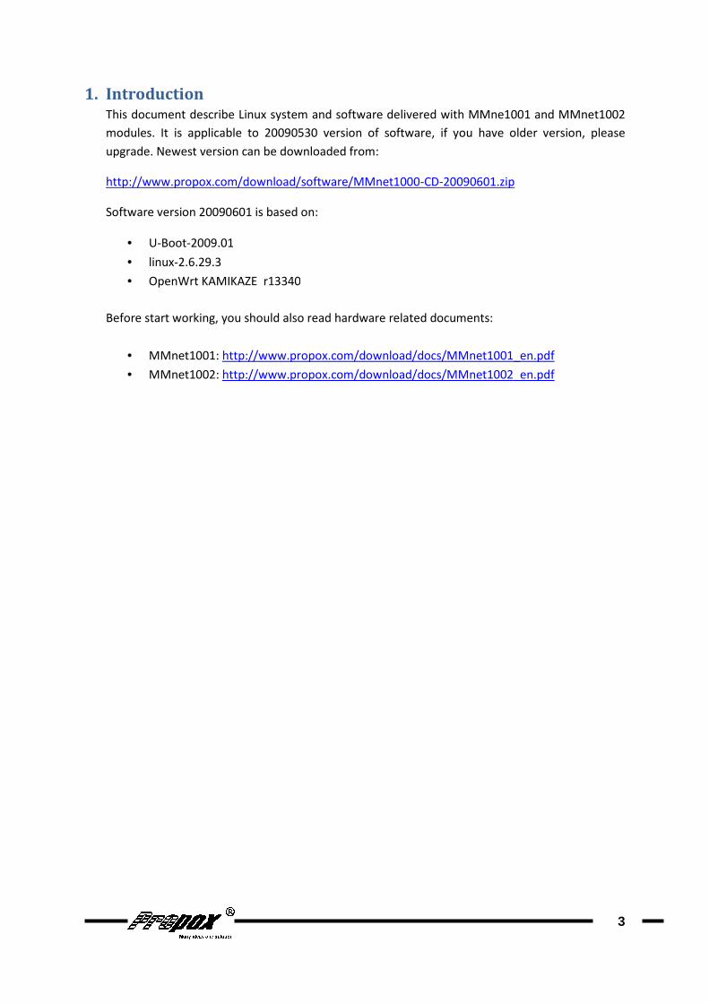
Example of connections on EVBmmTm evaluation board:
EVBmmTm peripheral Module socket
+3.3V C1
GND D1
RS232_1 RxD A7
RS232_1 TxD B7
RESET A16
USB DP B12
USB DM A12
HOST_USB T_D+ B10
HOST_USB T_D- A10
HOST_USB D_D+ B11
HOST_USB D_D- A11
RS232_2 RxD B5
RS232_2 TxD A5
CARD CS TBD.
CARD MOSI TBD.
CARD CLK TBD.
CARD MISO TBD.
CARD INS TBD.
CARD UNL TBD.
4
DBGU port of module to PC with use of level converter (you can use
Connect to module regulated 3.3V DC Power supply with 500mA capability. Pay
particular attention to this connection because module is not protected from
Connection
Necessary
Optional
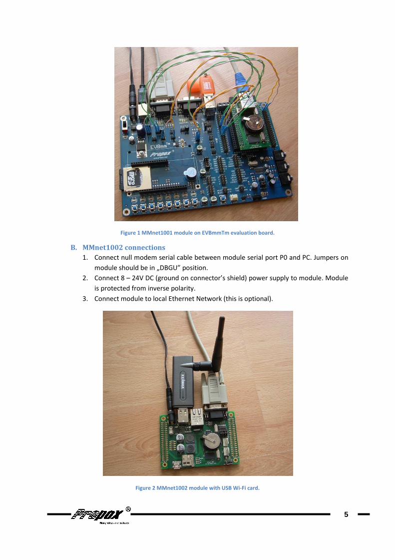
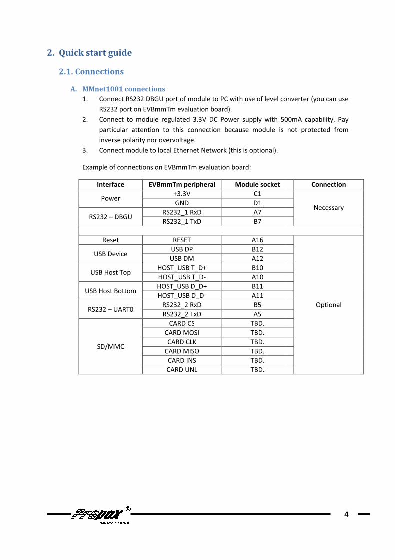
Figure 1 MMnet1001
B. MMnet1002 connections
1. Connect null modem serial cable between module serial port P0 and PC. Jumpers on
module should be in
2. Connect 8 – 24V DC (
is protected from inverse polarity
3. Connect module to loc
Figure
MMnet1001 module on EVBmmTm evaluation board.
connections
Connect null modem serial cable between module serial port P0 and PC. Jumpers on
module should be in „DBGU” position.
24V DC (ground on connector’s shield) power supply to module
is protected from inverse polarity.
Connect module to local Ethernet Network (this is optional).
Figure 2 MMnet1002 module with USB Wi-Fi card.
5
Connect null modem serial cable between module serial port P0 and PC. Jumpers on
power supply to module. Module

C. Start-up
Launch terminal emulator on PC. In Windows system it can be Putty
(http://www.putty.org/
connect to selected COM port with following settings: 115200 baud, 8 data bits, no
parity, 1 stop bit, no flow control. After applying power to module, debug information
will be displayed in terminal
Linux console will be available:
It is also possible to login to module through Ethernet. By default Telnet server is active
(login:root, no password
automatically disabled and instead of it SSH server is enabled
IP address is obtained from local DHCP Server, it can be checked with command
ifconfig eth0
or In DHCP server logs
RS232 interface is basic met
rescue procedure. If you do not have RS232 port in your PC, we recommend to obtain
USB/RS232 converter.
Launch terminal emulator on PC. In Windows system it can be Putty
http://www.putty.org/) in Linux it can be minicom. Configure terminal program to
connect to selected COM port with following settings: 115200 baud, 8 data bits, no
parity, 1 stop bit, no flow control. After applying power to module, debug information
will be displayed in terminal program. After system start up (few seconds) press Enter,
Linux console will be available:
Figure 3 Linux system after start up.
It is also possible to login to module through Ethernet. By default Telnet server is active
no password). After setting password (passwd command
automatically disabled and instead of it SSH server is enabled (after system reboot)
IP address is obtained from local DHCP Server, it can be checked with command
or In DHCP server logs.
RS232 interface is basic method of access to module. It is necessary in case of system
rescue procedure. If you do not have RS232 port in your PC, we recommend to obtain
USB/RS232 converter.
6
Launch terminal emulator on PC. In Windows system it can be Putty
Linux it can be minicom. Configure terminal program to
connect to selected COM port with following settings: 115200 baud, 8 data bits, no
parity, 1 stop bit, no flow control. After applying power to module, debug information
. After system start up (few seconds) press Enter,
It is also possible to login to module through Ethernet. By default Telnet server is active
command) Telnet Server is
(after system reboot).
IP address is obtained from local DHCP Server, it can be checked with command:
od of access to module. It is necessary in case of system
rescue procedure. If you do not have RS232 port in your PC, we recommend to obtain

3. Boot sequence and system
3.1. System start-up
Several pieces of software are involved in booting Linux system on module. This process is
described below:
3.2. ROMboot
This is a program in microprocessor’s ROM memory. Detailed description of it can be found
in MCU documentation in chapter 13
On MMnet1001/1002 modules ROMboot load AT91Boot program from first 4096 bytes of
NAND Flash memory to MCU internal SRAM memory and launch it.
3.3. AT91Boot
AT91Boot is a first stage bootloader
stage bootloader. Source code of AT91Boot adapted to MMnet1001/1002 modules can be
found on CD in file /src/Bootstrap
this archive in doc directory
AT91Boot configured for MMnet1001/1002 modules load program from NAND Flash
memory address 0x00040000 to SDRAM memory address
system components
Several pieces of software are involved in booting Linux system on module. This process is
This is a program in microprocessor’s ROM memory. Detailed description of it can be found
tation in chapter 13 „AT91SAM9260 Boot Program”.
On MMnet1001/1002 modules ROMboot load AT91Boot program from first 4096 bytes of
NAND Flash memory to MCU internal SRAM memory and launch it.
is a first stage bootloader. Its purpose is to initialize system and to load second
stage bootloader. Source code of AT91Boot adapted to MMnet1001/1002 modules can be
/src/Bootstrap-v1.10-MMnet1000.tar. Documentation is contained in
this archive in doc directory.
d for MMnet1001/1002 modules load program from NAND Flash
memory address 0x00040000 to SDRAM memory address 0x23F00000 and launch it
ROMboot
AT91Boot
U-Boot
Linux kernel
init process(system)
7
Several pieces of software are involved in booting Linux system on module. This process is
This is a program in microprocessor’s ROM memory. Detailed description of it can be found
On MMnet1001/1002 modules ROMboot load AT91Boot program from first 4096 bytes of
initialize system and to load second
stage bootloader. Source code of AT91Boot adapted to MMnet1001/1002 modules can be
Documentation is contained in
d for MMnet1001/1002 modules load program from NAND Flash
and launch it.
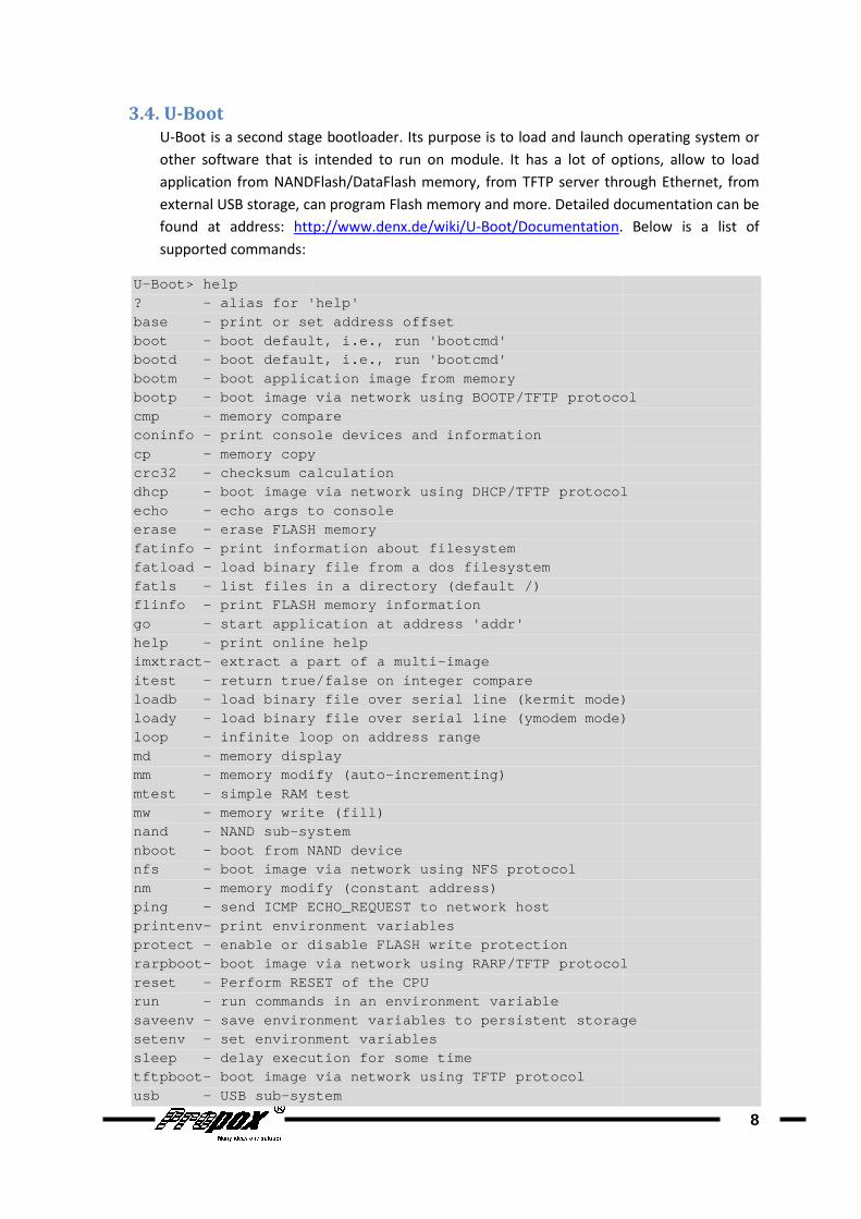
3.4. U-Boot
U-Boot is a second stage bootloader
other software that is
application from NANDFlash/DataFlash memory, from TFTP server
external USB storage, can program Flash memory and more. Detailed documentation can be
found at address: http://www.denx.de/wiki/U
supported commands:
U-Boot> help ? - alias for 'help'base - print or set address offsetboot - boot default, i.e., run 'bootcmd'bootd - boot default, i.e., run 'bootcmd'bootm - boot application image from memorybootp - boot image via network cmp - memory compareconinfo - print console devices and informationcp - memory copycrc32 - checksum calculationdhcp - boot image via network using DHCP/TFTP protocolecho - echo args to consoleerase - erase FLASH memoryfatinfo - print information about filesystemfatload - load binary file from a dos filesystemfatls - list files in a directory (default /)flinfo - print FLASH memory informationgo - start application at address 'addr'help - pri nt online helpimxtract- extract a part of a multiitest - return true/false on integer compareloadb - load binary file over serial line (kermit mode)loady - load binary file over serial line (ymodem mode)loop - infinite loop on address rmd - memory displaymm - memory modify (automtest - simple RAM testmw - memory write (fill)nand - NAND sub- systemnboot - boot from NAND devicenfs - boot image via network using NFS protocolnm - memory modify (constant address)ping - send ICMP ECHO_REQUEST to network hostprintenv- print environment variablesprotect - enable or disable FLASH write protectionrarpboot- boot image via network using RARP/TFTP protocolreset - Perform RESET of the CPrun - run commands in an environment variablesaveenv - save environment variables to persistent storagesetenv - set environment variablessleep - delay execution for some timetftpboot- boot image via network using TFTP protocolusb - USB sub- system
is a second stage bootloader. Its purpose is to load and launch operating system or
intended to run on module. It has a lot of options, allow to load
application from NANDFlash/DataFlash memory, from TFTP server through
external USB storage, can program Flash memory and more. Detailed documentation can be
http://www.denx.de/wiki/U-Boot/Documentation.
alias for 'help' print or set address offset boot default, i.e., run 'bootcmd' boot default, i.e., run 'bootcmd' boot application image from memory boot image via network using BOOTP/TFTP protocolmemory compare print console devices and information memory copy checksum calculation boot image via network using DHCP/TFTP protocolecho args to console
FLASH memory print information about filesystem load binary file from a dos filesystem list files in a directory (default /) print FLASH memory information start application at address 'addr'
nt online help extract a part of a multi -image return true/false on integer compare load binary file over serial line (kermit mode)load binary file over serial line (ymodem mode)infinite loop on address r ange memory display memory modify (auto -incrementing) simple RAM test memory write (fill)
system boot from NAND device boot image via network using NFS protocol
modify (constant address) send ICMP ECHO_REQUEST to network host print environment variables enable or disable FLASH write protection boot image via network using RARP/TFTP protocolPerform RESET of the CP U run commands in an environment variable save environment variables to persistent storageset environment variables delay execution for some time boot image via network using TFTP protocol
system
8
Its purpose is to load and launch operating system or
It has a lot of options, allow to load
through Ethernet, from
external USB storage, can program Flash memory and more. Detailed documentation can be
. Below is a list of
using BOOTP/TFTP protocol
boot image via network using DHCP/TFTP protocol
load binary file over serial line (kermit mode) load binary file over serial line (ymodem mode)
boot image via network using RARP/TFTP protocol
save environment variables to persistent storage

usbboot - boot from USB deviceversion - print monitor version
To get access to U-Boot console you have to press any key at boot:
RomBOOT >AT91Boot-20081201 U- Boot 2009.01 (Mar 20 2009 DRAM: 64 MB NAND: 1024 MiB In: serial Out: serial Err: serial Net: macb0 macb0: Starting autonegotiation...macb0: Autonegotiation completemacb0: link up, 100Mbps fullHit any key to stop autoboot: 0U-Boot>
Source code of U-Boot adapter to MMnet1001/1002 boards can
/sources/u-boot-2009.01
and modified to work with modules
3.5. Linux Kernel
Modules use standard 2.6.29.3 Linux kernel version, which has full support of
AT91SAM9260/AT91SAM9G20
can be found on CD in archive:
documentation can be found at
Documentation directory
Peripherals supported by kernel:
• Serial ports
• Ethernet
• USB Host
• USB Device
• MMC / SD
• I2C
3.6. The System
Linux system delivered
(http://openwrt.org/).
Documentation and user forum can be found on above website
boot from USB device print monitor version
Boot console you have to press any key at boot:
Boot 2009.01 (Mar 20 2009 - 13:43:24)
macb0: Starting autonegotiation... macb0: Autonegotiation complete macb0: link up, 100Mbps full -duplex (lpa: 0x45e1) Hit any key to stop autoboot: 0
Boot adapter to MMnet1001/1002 boards can be found on CD in archive
2009.01-MMnet1000.tar.gz. Configuration file at91sam9260ek
and modified to work with modules.
Modules use standard 2.6.29.3 Linux kernel version, which has full support of
AT91SAM9260/AT91SAM9G20 microprocessors. Sources adapted to MMnet1000
can be found on CD in archive: /sources/linux-2.6.29.3-MMnet1000.tar.gz.
documentation can be found at http://www.kernel.org/doc/ and in sources in
directory.
Peripherals supported by kernel:
• SPI
• SSC
• RTT (as RTC)
• Watchdog
• NAND Flash
• Compact Flash
delivered with module is based on OpenWrt
Documentation and user forum can be found on above website.
9
be found on CD in archive
at91sam9260ek was used
Modules use standard 2.6.29.3 Linux kernel version, which has full support of
MMnet1000 modules
MMnet1000.tar.gz. Kernel
and in sources in
OpenWrt distribution

In base system following commands are available
[, [[, addgroup, adduser, adjtimex, ar, arp, arping , ash,awk, basename, bbconfig, brctl, bunzip2, bzcat, bzip2, c at,catv, chat, chgrp, chmod, chown, chpst, chroot, chr t, chvt,cksum, clear, comm, cp, crond, crontab, cut, date, dd, delgroup,deluser, df, dhcprelay, diff, dirname, dmesg, dnsd, dpkg,dpkg-deb, du, dump leases, echo, egrep, env, envdir, envuidgid,ether- wake, expr, fakeidentd, false, fetchmail, fgrep, fi nd,fold, free, ftpget, ftpput, fuser, getty, grep, gun zip,gzip, halt, head, hexdump, hostid, hostname, httpd, hwclock,id, ifconfig, ifdown, ifenslave, insmod, install, ip, ipaddr, ipcalc, iplink, iprout e, iprule,iptunnel, kill, killall, killall5, klogd, last, len gth,less, ln, lock, logger, login, logname, logread, ls , lsmod,lzmacat, makedevs, md5sum, mdev, mesg, microcom, mkfifo, mknod, mkswap, mktemp, modprobe, more, moun t, mountpoint,mv, nameif, nc, netmsg, netstat, nice, nmeter, nslo okup,openvt, passwd, pgrep, pidof, ping, ping6, pivot_ro ot, pkill,poweroff, printenv, printf, ps, pscan, pwd, rdate, readahead,re adlink, realpath, reboot, renice, reset, resize, rm , rmdir,rmmod, route, rpm, rtcwake, runlevel, runsv, runsvd ir, rx,sed, sendmail, seq, setconsole, setkeycodes, setsid , setuidgid,sh, sleep, softlimit, sort, split, startstrings, stty , su, sulogin, sv, svlogd, swapoff, swapon,switch_root, sync, sysctl, syslogd, tail, tar, tcps vd, tee,telnet, telnetd, test, tftp, tftpd, time, top, touc h, tr,traceroute, true, tty, ttysize, udhcpc, udhcpd, udp svd,umount, uname, uniq, unlzma, unzip, upvi, watch, watchdog, wc, wget, which, who, whoami, xargs,yes, zcat, zcip
In addition, dropbear (
installed:
dropbear iwconfig, iwgetid, iwlist, wpriv, iwspyflash_erase, flash_eraseall, flash_info, flash_lock, flash_unlock,flashcp, nanddump, nandtest, nandwrite , ubiattach, ubidetach, ubiformat, ubimkvol, ubirmvol, ubiupdatevol
OpenWrt has packages management system opkg
software packages (their are also on CD)
http://www.propox.com/download/linux/at91/packages/Packages.gz
To list available packages in module conso
opkg update opkg list
To install selected module
In base system following commands are available:
[, [[, addgroup, adduser, adjtimex, ar, arp, arping , ash,basename, bbconfig, brctl, bunzip2, bzcat, bzip2, c at,
catv, chat, chgrp, chmod, chown, chpst, chroot, chr t, chvt,cksum, clear, comm, cp, crond, crontab, cut, date, dd, delgroup,deluser, df, dhcprelay, diff, dirname, dmesg, dnsd, dpkg,
leases, echo, egrep, env, envdir, envuidgid,wake, expr, fakeidentd, false, fetchmail, fgrep, fi nd,
fold, free, ftpget, ftpput, fuser, getty, grep, gun zip, gzip, halt, head, hexdump, hostid, hostname, httpd, hwclock,id, ifconfig, ifdown, ifenslave, ifup, inetd, init, inotifyd,insmod, install, ip, ipaddr, ipcalc, iplink, iprout e, iprule,iptunnel, kill, killall, killall5, klogd, last, len gth, less, ln, lock, logger, login, logname, logread, ls , lsmod,lzmacat, makedevs, md5sum, mdev, mesg, microcom, mkdir, mkfifo, mknod, mkswap, mktemp, modprobe, more, moun t, mountpoint,mv, nameif, nc, netmsg, netstat, nice, nmeter, nslo okup, openvt, passwd, pgrep, pidof, ping, ping6, pivot_ro ot, pkill,poweroff, printenv, printf, ps, pscan, pwd, rdate, readahead,
adlink, realpath, reboot, renice, reset, resize, rm , rmdir,rmmod, route, rpm, rtcwake, runlevel, runsv, runsvd ir, rx,sed, sendmail, seq, setconsole, setkeycodes, setsid , setuidgid,sh, sleep, softlimit, sort, split, start -stop- daemon, stat,
, su, sulogin, sv, svlogd, swapoff, swapon, switch_root, sync, sysctl, syslogd, tail, tar, tcps vd, tee,telnet, telnetd, test, tftp, tftpd, time, top, touc h, tr,traceroute, true, tty, ttysize, udhcpc, udhcpd, udp svd, umount, uname, uniq, unlzma, unzip, up time, usleep, vconfig,vi, watch, watchdog, wc, wget, which, who, whoami, xargs,
dropbear (SSH client/server), wireless tools and mtd
iwconfig, iwgetid, iwlist, wpriv, iwspy flash_eraseall, flash_info, flash_lock,
flash_unlock,flashcp, nanddump, nandtest, nandwrite , ubiattach, ubiformat, ubimkvol, ubirmvol, ubiupdatevol
OpenWrt has packages management system opkg. On our webserver can be found about 300
(their are also on CD). List of packages with description is here
http://www.propox.com/download/linux/at91/packages/Packages.gz
To list available packages in module console:
To install selected module:
10
[, [[, addgroup, adduser, adjtimex, ar, arp, arping , ash, basename, bbconfig, brctl, bunzip2, bzcat, bzip2, c at,
catv, chat, chgrp, chmod, chown, chpst, chroot, chr t, chvt, cksum, clear, comm, cp, crond, crontab, cut, date, dd, delgroup, deluser, df, dhcprelay, diff, dirname, dmesg, dnsd, dpkg,
leases, echo, egrep, env, envdir, envuidgid, wake, expr, fakeidentd, false, fetchmail, fgrep, fi nd,
gzip, halt, head, hexdump, hostid, hostname, httpd, hwclock, ifup, inetd, init, inotifyd,
insmod, install, ip, ipaddr, ipcalc, iplink, iprout e, iprule,
less, ln, lock, logger, login, logname, logread, ls , lsmod,
mkfifo, mknod, mkswap, mktemp, modprobe, more, moun t, mountpoint,
openvt, passwd, pgrep, pidof, ping, ping6, pivot_ro ot, pkill, poweroff, printenv, printf, ps, pscan, pwd, rdate, readahead,
adlink, realpath, reboot, renice, reset, resize, rm , rmdir, rmmod, route, rpm, rtcwake, runlevel, runsv, runsvd ir, rx, sed, sendmail, seq, setconsole, setkeycodes, setsid , setuidgid,
daemon, stat,
switch_root, sync, sysctl, syslogd, tail, tar, tcps vd, tee, telnet, telnetd, test, tftp, tftpd, time, top, touc h, tr,
time, usleep, vconfig, vi, watch, watchdog, wc, wget, which, who, whoami, xargs,
mtd-tools packages are
flash_unlock,flashcp, nanddump, nandtest, nandwrite , ubiattach,
On our webserver can be found about 300
List of packages with description is here:

opkg update opkg install module_name
(opkg update can be executed only once after every system reboot
More options:
opkg
module_name
can be executed only once after every system reboot).
11
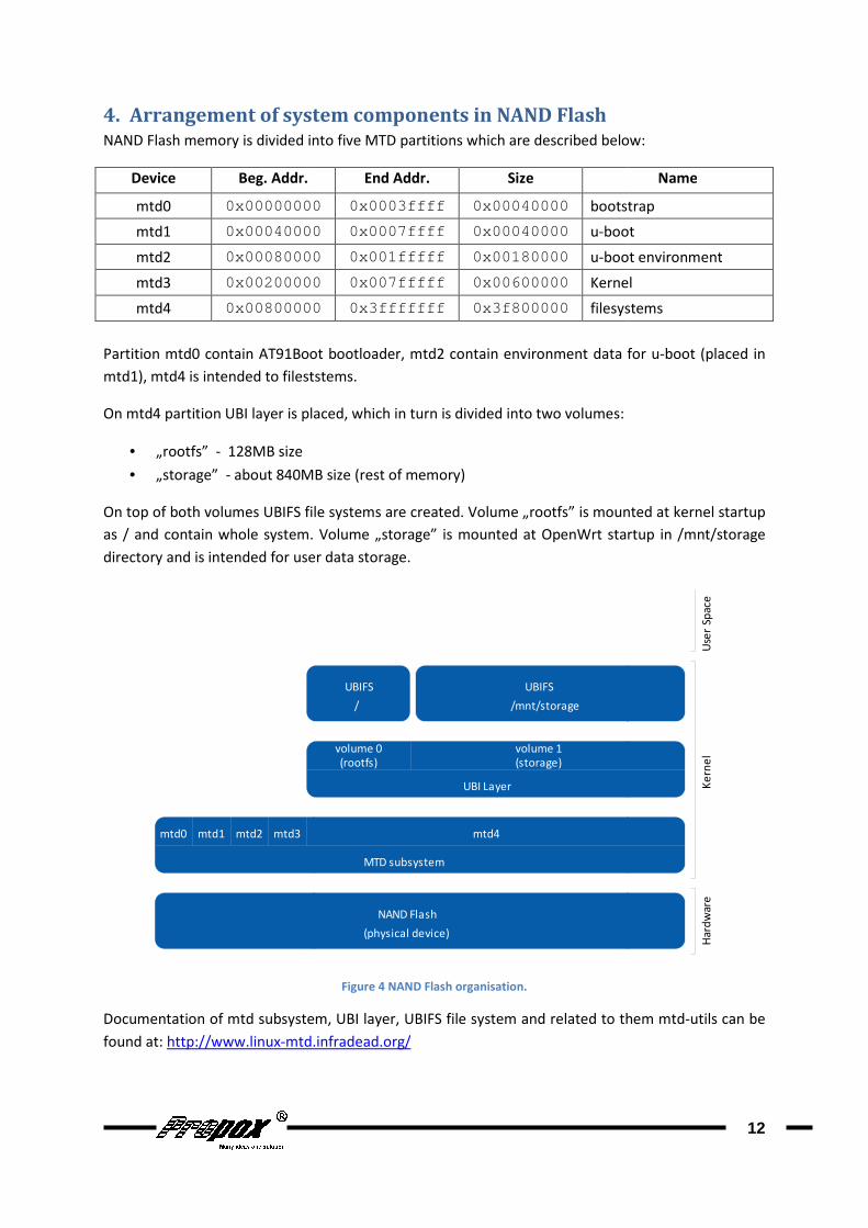
4. Arrangement of system components in
NAND Flash memory is divided into five MTD partitions which are described below:
Device Beg. Addr.
mtd0 0x00000000
mtd1 0x00040000
mtd2 0x00080000
mtd3 0x00200000
mtd4 0x00800000
Partition mtd0 contain AT91Boot bootloader, mtd2 contain environment data for u
mtd1), mtd4 is intended to fileststems
On mtd4 partition UBI layer is placed, which in turn is divided into two volumes:
• „rootfs” - 128MB size
• „storage” - about 840MB
On top of both volumes UBIFS file systems are created
as / and contain whole system.
directory and is intended for user data storage
Documentation of mtd subsystem, UBI layer, UBIFS file system and related to them
found at: http://www.linux-mtd.infradead.org/
mtd0 mtd1 mtd2 mtd3
of system components in NAND Flash
into five MTD partitions which are described below:
End Addr. Size
0x00000000 0x0003ffff 0x00040000 bootstrap
0x00040000 0x0007ffff 0x00040000 u-boot
0x00080000 0x001fffff 0x00180000 u-boot environment
0x00200000 0x007fffff 0x00600000 Kernel
0x00800000 0x3fffffff 0x3f800000 filesystems
Partition mtd0 contain AT91Boot bootloader, mtd2 contain environment data for u
, mtd4 is intended to fileststems.
is placed, which in turn is divided into two volumes:
840MB size (rest of memory)
On top of both volumes UBIFS file systems are created. Volume „rootfs” is mounted at kernel startup
. Volume „storage” is mounted at OpenWrt startup in
directory and is intended for user data storage.
Figure 4 NAND Flash organisation.
Documentation of mtd subsystem, UBI layer, UBIFS file system and related to them
mtd.infradead.org/
NAND Flash
MTD subsystem
mtd4
UBI Layer
volume 0 volume 1
(storage)(rootfs)
UBIFS
/mnt/storage
UBIFS
/
(physical device)
12
into five MTD partitions which are described below:
Name
bootstrap
boot
boot environment
ernel
filesystems
Partition mtd0 contain AT91Boot bootloader, mtd2 contain environment data for u-boot (placed in
is mounted at kernel startup
is mounted at OpenWrt startup in /mnt/storage
Documentation of mtd subsystem, UBI layer, UBIFS file system and related to them mtd-utils can be
Hard
war
eK
ern
el
Use
r Sp
ace

5. Software upgrade To perform software upgrade you need PC computer with TFTP server installed, from which software
will be downloaded. As TFTP server in Windows system may be used simple to configure Tftpd32, it
can be found at: http://tftpd32.jounin.net/
configured (description can be found in attac
available at IP address 192.168.1.20.
5.1. Kernel upgrade
5.1.1. From Linux
Download new kernel image from TFTP server
tftp –g – r uImage 192.168.1.20
Erase mtd partition with kernel:
flash_eraseall /dev/mtd3
Write new kernel to mtd partition
nandwrite –p – m /dev/mtd3 uImage
5.1.2. From U-Boot
Download new kernel image from TFTP server
tftp 0x22000000 192.168.1.20:uImage
Erase region in NAND Flash containing kernel
nand erase 0x 200000 0x
Write new kernel to NAND Flash
nand write 0x22000000 0x200000 0x
Modules for new kernel should be copied to
5.2. Installing system from scratch
WARNING: after this operations all data in NAND Flash memory will be lost
PC should have installed
deliver this software only for Windows system,
tested by us:
http://www.linux4sam.org/twiki/bin/view/Linux4SAM/SoftwareTools#SAM_BA_Linux_initiat
ive
Local Ethernet Network, where module is connected, should have DHCP server
1. Launch ROMBoot bootloader on module. To do this, you need to erase
NAND Flash.
To perform software upgrade you need PC computer with TFTP server installed, from which software
server in Windows system may be used simple to configure Tftpd32, it
http://tftpd32.jounin.net/ (it is included on CD). In Linux system, tftpd should be
configured (description can be found in attachment to this document). TFTP server should be
192.168.1.20.
Download new kernel image from TFTP server:
r uImage 192.168.1.20
Erase mtd partition with kernel:
flash_eraseall /dev/mtd3
kernel to mtd partition:
m /dev/mtd3 uImage
Download new kernel image from TFTP server:
tftp 0x22000000 192.168.1.20:uImage
Erase region in NAND Flash containing kernel:
200000 0x 600000
Write new kernel to NAND Flash:
0x22000000 0x200000 0x 600000
Modules for new kernel should be copied to /lib/modules.
Installing system from scratch
after this operations all data in NAND Flash memory will be lost
PC should have installed SAM-BA (AT91-ISP) software from Atmel (on CD)
deliver this software only for Windows system, there is also Linux equivalent, but it wasn’t
http://www.linux4sam.org/twiki/bin/view/Linux4SAM/SoftwareTools#SAM_BA_Linux_initiat
Local Ethernet Network, where module is connected, should have DHCP server
Launch ROMBoot bootloader on module. To do this, you need to erase
13
To perform software upgrade you need PC computer with TFTP server installed, from which software
server in Windows system may be used simple to configure Tftpd32, it
In Linux system, tftpd should be
TFTP server should be
after this operations all data in NAND Flash memory will be lost!
CD). Atmel officially
there is also Linux equivalent, but it wasn’t
http://www.linux4sam.org/twiki/bin/view/Linux4SAM/SoftwareTools#SAM_BA_Linux_initiat
Local Ethernet Network, where module is connected, should have DHCP server.
Launch ROMBoot bootloader on module. To do this, you need to erase AT91Boot from

To erase AT91Boot
flash_eraseall /dev/mtd0
To erase AT91Boot from U
nand erase 0x0 0x40000
If you don’t have access to Linux nor U
(USE LED diode should lit) and tw
should see “ RomBOOT
2. Connect module’s USB Device port to PC. In Device Manager new USB device
„atm6124.Sys ATMEL AT91xxxxx Test Board”
3. From flashing directory on CD launch
programming log should appear, you can close it
attachment to this document
to NAND Flash memory
4. Make content of directory /flashing/tftp from CD available in
192.168.1.20).
5. After resetting module (it is necessary to cycle Power) U
download from TFTP server to SDRAM memory special version of Linux ker
for programming system to Flash memory
6. When Linux system start and console is available type:
./program
This will download system image and program it to NAND Flash
Linux will reboot to newly programmed system
AT91Boot from Linux console:
flash_eraseall /dev/mtd0
To erase AT91Boot from U-Boot console:
nand erase 0x0 0x40000
If you don’t have access to Linux nor U-Boot console, close SAMBA jumper on module
(USE LED diode should lit) and two times switch on/off power. In DBGU terminal you
RomBOOT” (and no other messages after this). Remove SAMBA jumper
Connect module’s USB Device port to PC. In Device Manager new USB device
„atm6124.Sys ATMEL AT91xxxxx Test Board” should appear.
directory on CD launch "MMnet1000_prog.bat".
programming log should appear, you can close it (example of correct log file is in
attachment to this document). AT91Boot and U-Boot bootloaders are now programmed
to NAND Flash memory.
Make content of directory /flashing/tftp from CD available in TFTP
After resetting module (it is necessary to cycle Power) U-Boot will launch and will
download from TFTP server to SDRAM memory special version of Linux ker
for programming system to Flash memory.
When Linux system start and console is available type:
This will download system image and program it to NAND Flash
Linux will reboot to newly programmed system.
14
Boot console, close SAMBA jumper on module
on/off power. In DBGU terminal you
Remove SAMBA jumper.
Connect module’s USB Device port to PC. In Device Manager new USB device
"MMnet1000_prog.bat". After few seconds
example of correct log file is in
bootloaders are now programmed
TFTP server (at address
Boot will launch and will
download from TFTP server to SDRAM memory special version of Linux kernel prepared
This will download system image and program it to NAND Flash. After programming
6. Peripherals handling
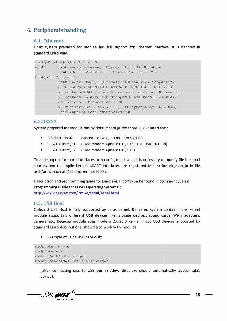
6.1. Ethernet
Linux system prepared for module has full
standard Linux way.
root@MMnet:/# ifconfig eth0eth0 Link encap:Ethernet HWaddr 3A:1F:34:08:5 4:54 inet addr:192.168.1.Mask:255.255.255.0 inet6 addr: fe80::381f:34ff:fe08:5454/64 Scope:Link UP BROADCAST RUNNING MULTICAST MTU:1500 Metric:1 RX packets:1941 errors:0 dropped:0 overruns:0 frame :0 TX packets:55 e collisions:0 txqueuelen:1000 RX bytes:218829 (213.7 KiB) TX bytes:6655 (6.4 KiB ) Interrupt:21 Base address:0x4000
6.2. RS232
System prepared for module has by default configured three RS232 i
• DBGU as ttyS0 (
• USART0 as ttyS1 (
• USART1 as ttyS2 (
To add support for more interfaces or reconfigure e
sources and recompile kernel. USART interfaces are registered in function
arch/arm/mach-at91/board-
Description and programming guide for Linux serial ports can be found in document
Programming Guide for POSIX Operating Systems”:
http://www.easysw.com/~mike/serial/serial.html
6.3. USB Host
Onboard USB Host is fully supported by Linux kernel
module supporting different USB
camera etc. Because module uses modern 2.6.29.3 kernel, most USB devices supported by
standard Linux distributions, should also
• Example of using USB hard disk
modprobe sd_mod modprobe vfat mkdir /mnt/usbstorage/mount /dev/sda1 /mnt/usbstorage/
(after connecting disc to USB bus in
device).
Peripherals handling
Linux system prepared for module has full support for Ethernet interface. It is handled in
root@MMnet:/# ifconfig eth0 eth0 Link encap:Ethernet HWaddr 3A:1F:34:08:5 4:54
inet addr:192.168.1. 13 Bcast:192.168.1.255
inet6 addr: fe80::381f:34ff:fe08:5454/64 Scope:LinkUP BROADCAST RUNNING MULTICAST MTU:1500 Metric:1RX packets:1941 errors:0 dropped:0 overruns:0 frame :0TX packets:55 e rrors:0 dropped:0 overruns:0 carrier:0collisions:0 txqueuelen:1000 RX bytes:218829 (213.7 KiB) TX bytes:6655 (6.4 KiB )Interrupt:21 Base address:0x4000
System prepared for module has by default configured three RS232 interfaces
(system console, no modem signals)
(used modem signals: CTS, RTS, DTR, DSR, DCD, RI)
(used modem signals: CTS, RTS)
for more interfaces or reconfigure existing it is necessary to modif
sources and recompile kernel. USART interfaces are registered in function
-mmnet1000.c .
Description and programming guide for Linux serial ports can be found in document
for POSIX Operating Systems”:
http://www.easysw.com/~mike/serial/serial.html
Host is fully supported by Linux kernel. Delivered system contain many kernel
module supporting different USB devices like, storage devices, sound cards, Wi
camera etc. Because module uses modern 2.6.29.3 kernel, most USB devices supported by
standard Linux distributions, should also work with modules.
Example of using USB hard disk:
mkdir /mnt/usbstorage/ mount /dev/sda1 /mnt/usbstorage/
after connecting disc to USB bus in /dev/ directory should automatically
15
for Ethernet interface. It is handled in
inet6 addr: fe80::381f:34ff:fe08:5454/64 Scope:Link UP BROADCAST RUNNING MULTICAST MTU:1500 Metric:1 RX packets:1941 errors:0 dropped:0 overruns:0 frame :0
rrors:0 dropped:0 overruns:0 carrier:0
RX bytes:218829 (213.7 KiB) TX bytes:6655 (6.4 KiB )
nterfaces:
: CTS, RTS, DTR, DSR, DCD, RI)
xisting it is necessary to modify file in kernel
sources and recompile kernel. USART interfaces are registered in function ek_map_io in file
Description and programming guide for Linux serial ports can be found in document „Serial
Delivered system contain many kernel
like, storage devices, sound cards, Wi-Fi adapters,
camera etc. Because module uses modern 2.6.29.3 kernel, most USB devices supported by
automatically appear sda1
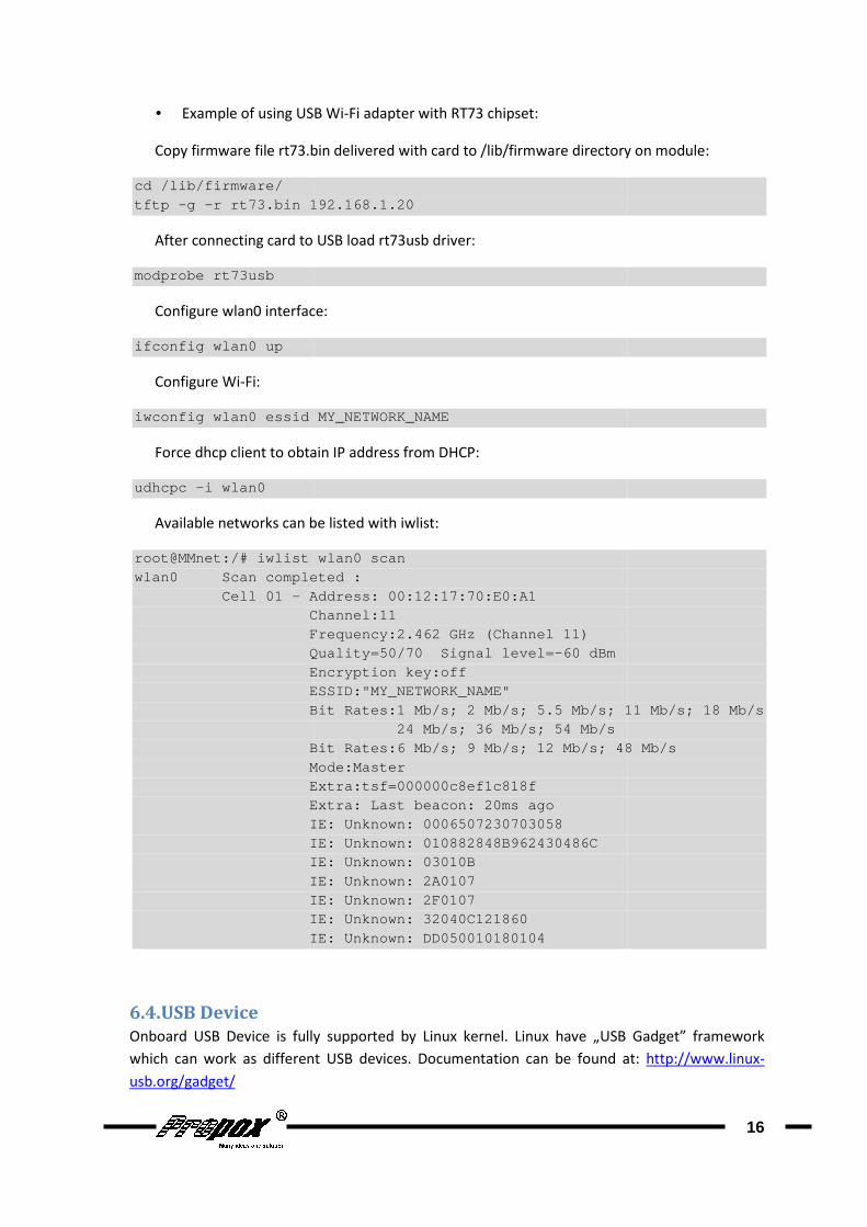
• Example of using USB
Copy firmware file rt73.bin
cd /lib/firmware/ tftp -g - r rt73.bin 192.168.1.20
After connecting card to USB load rt73usb driver
modprobe rt73usb
Configure wlan0 interface
ifconfig wlan0 up
Configure Wi-Fi:
iwconfig wlan0 essid MY_NETWORK_NAME
Force dhcp client to obtain
udhcpc -i wlan0
Available networks can be listed with
root@MMnet:/# iwlist wlan0 scanwlan0 Scan completed : Cell 01 - Address: 00:12:17:70:E0:A1 Channel:11 Frequency:2.462 GHz (Channel 11) Quality=50/70 Signal level= Encryption key:off ESSID:"MY_ Bit Rates:1 Mb/s; 2 Mb/s; 5.5 Mb/s; 11 Mb/s; 18 Mb/ s Bit Rates:6 Mb/s; 9 Mb/s; 12 Mb/s; 48 Mb/s Mode:Master Extra:tsf=000000c8ef1c818f Extra: Last beacon: 20ms ago IE: Unknown: 0006507230703058 IE: Unknown: 010882848B962430486C IE: Unknown: 03010B IE: Unknown: 2 IE: Unknown: 2F0107 IE: Unknown: 32040C121860 IE: Unknown: DD050010180104
6.4. USB Device
Onboard USB Device is fully supported by Linux kernel
which can work as different USB devices
usb.org/gadget/
Example of using USB Wi-Fi adapter with RT73 chipset:
rt73.bin delivered with card to /lib/firmware directory on module
r rt73.bin 192.168.1.20
After connecting card to USB load rt73usb driver:
rface:
iwconfig wlan0 essid MY_NETWORK_NAME
Force dhcp client to obtain IP address from DHCP:
Available networks can be listed with iwlist:
root@MMnet:/# iwlist wlan0 scan wlan0 Scan completed :
Address: 00:12:17:70:E0:A1 Channel:11 Frequency:2.462 GHz (Channel 11) Quality=50/70 Signal level= -60 dBm Encryption key:off ESSID:"MY_ NETWORK_NAME" Bit Rates:1 Mb/s; 2 Mb/s; 5.5 Mb/s; 11 Mb/s; 18 Mb/ s
24 Mb/s; 36 Mb/s; 54 Mb/s Bit Rates:6 Mb/s; 9 Mb/s; 12 Mb/s; 48 Mb/sMode:Master Extra:tsf=000000c8ef1c818f Extra: Last beacon: 20ms ago IE: Unknown: 0006507230703058 IE: Unknown: 010882848B962430486C IE: Unknown: 03010B IE: Unknown: 2 A0107 IE: Unknown: 2F0107 IE: Unknown: 32040C121860 IE: Unknown: DD050010180104
Onboard USB Device is fully supported by Linux kernel. Linux have „USB Gadget”
as different USB devices. Documentation can be found at
16
delivered with card to /lib/firmware directory on module:
Bit Rates:1 Mb/s; 2 Mb/s; 5.5 Mb/s; 11 Mb/s; 18 Mb/ s
Bit Rates:6 Mb/s; 9 Mb/s; 12 Mb/s; 48 Mb/s
„USB Gadget” framework
Documentation can be found at: http://www.linux-
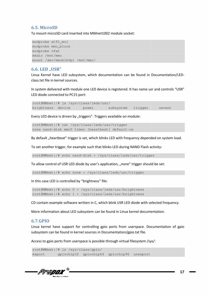
6.5. MicroSD
To mount microSD card inserted into MMnet1002 module socket:
modprobe at91_mci modprobe mmc_block modprobe vfat mkdir /mnt/mmc mount /dev/mmcblk0p1 /mnt/mmc/
6.6. LED „USR”
Linux Kernel have LED subsystem, which documentation can be found in
class.txt file in kernel sources
In system delivered with module one LED device is registered. It has name
LED diode connected to PC15 port
root@MMnet:/# ls /sys/class/leds/usr/brightness device power subsystem tri gger uevent
Every LED device is driven by „triggers”. Triggers available on module
root@MMnet:/# cat /sys/class/leds/usr/triggernone nand- disk mmc0 timer [heartbeat] default
By default „heartbeat” trigger is set, which blinks LED with frequency depended on system load.
To set another trigger, for example such that blinks LED during NAND Flash activity
root@MMnet:/# echo nand
To allow control of USR LED diode by user’s application, „none” trigger should be set
root@MMnet:/# echo none > /sys/class/leds/usr/trigg er
In this case LED is controlled by
r oot@MMnet:/# echo 0 > /sys/class/leds/usr/brightnes sroot@MMnet:/# echo 1 > /sys/class/leds/usr/brightne ss
CD contain example software written in C, which blink USR LED diode with selected frequency
More information about LED subsystem can be found in Lin
6.7. GPIO
Linux kernel have support
subsystem can be found in kernel sources in
Access to gpio ports from userspace is possible through
root@MMnet:/# ls /sys/class/gpio/export gpiochip32 gpiochip64 gpiochip96 une xport
To mount microSD card inserted into MMnet1002 module socket:
mount /dev/mmcblk0p1 /mnt/mmc/
Linux Kernel have LED subsystem, which documentation can be found in Documentatio
file in kernel sources.
In system delivered with module one LED device is registered. It has name usr and controls “USR”
LED diode connected to PC15 port:
root@MMnet:/# ls /sys/class/leds/usr/ brightness device power subsystem tri gger uevent
Every LED device is driven by „triggers”. Triggers available on module:
/sys/class/leds/usr/trigger disk mmc0 timer [heartbeat] default -on
By default „heartbeat” trigger is set, which blinks LED with frequency depended on system load.
To set another trigger, for example such that blinks LED during NAND Flash activity
root@MMnet:/# echo nand - disk > /sys/class/leds/usr/trigger
To allow control of USR LED diode by user’s application, „none” trigger should be set
root@MMnet:/# echo none > /sys/class/leds/usr/trigg er
In this case LED is controlled by “brightness” file:
oot@MMnet:/# echo 0 > /sys/class/leds/usr/brightnes s root@MMnet:/# echo 1 > /sys/class/leds/usr/brightne ss
CD contain example software written in C, which blink USR LED diode with selected frequency
More information about LED subsystem can be found in Linux kernel documentation
for controlling gpio ports from userspace. Documentation of gpio
subsystem can be found in kernel sources in Documentation/gpio.txt file.
ess to gpio ports from userspace is possible through virtual filesystem /sys/
root@MMnet:/# ls /sys/class/gpio/ export gpiochip32 gpiochip64 gpiochip96 une xport
17
Documentation/LED-
usr and controls “USR”
brightness device power subsystem tri gger uevent
By default „heartbeat” trigger is set, which blinks LED with frequency depended on system load.
To set another trigger, for example such that blinks LED during NAND Flash activity:
disk > /sys/class/leds/usr/trigger
To allow control of USR LED diode by user’s application, „none” trigger should be set:
CD contain example software written in C, which blink USR LED diode with selected frequency.
ux kernel documentation.
for controlling gpio ports from userspace. Documentation of gpio
virtual filesystem /sys/:
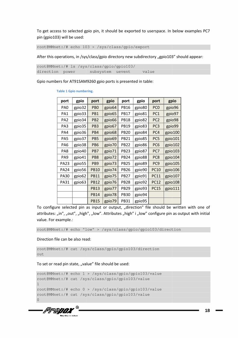
To get access to selected gpio pin, it should be exported to userspace
pin (gpio103) will be used:
root@MMnet:/# echo 103
After this operations, in /sys/class/gpio
root@MMnet:/# ls /sys/class/gpio/gpiodirection power subsystem uevent value
Gpio numbers for AT91SAM9260
Table 1 Gpio numbering
port gpio
PA0 gpio32
PA1 gpio33
PA2 gpio34
PA3 gpio35
PA4 gpio36
PA5 gpio37
PA6 gpio38
PA8 gpio40
PA9 gpio41
PA23 gpio55
PA24 gpio56
PA30 gpio62
PA31 gpio63
To configure selected pin as input or output,
attributes: „in", „out”, „high”, „low”.
value. For example.:
root@MMnet:/# echo "low" > /sys/class/gpio/gpio
Direction file can be also read
root@MMnet:/# cat /sys/class/gpio/gpioout
To set or read pin state, „value” file should be used
root@MMnet:/# echo 1 > /sys/class/gpio/gpioroot@MMnet:/# cat /sys/class/gpio/gpio1 root@MMnet:/# echo 0 > /sys/claroot@MMnet:/# cat /sys/class/gpio/gpio0
To get access to selected gpio pin, it should be exported to userspace. In below examples PC7
103 > /sys/class/gpio/export
/sys/class/gpio directory new subdirectory „gpio103” should appear
root@MMnet:/# ls /sys/class/gpio/gpio 103/ direction power subsystem uevent value
AM9260 gpio ports is presented in table:
Gpio numbering.
port gpio port gpio port gpio
gpio32 PB0 gpio64 PB16 gpio80 PC0 gpio96
gpio33 PB1 gpio65 PB17 gpio81 PC1 gpio97
gpio34 PB2 gpio66 PB18 gpio82 PC2 gpio98
gpio35 PB3 gpio67 PB19 gpio83 PC3 gpio99
gpio36 PB4 gpio68 PB20 gpio84 PC4 gpio100
gpio37 PB5 gpio69 PB21 gpio85 PC5 gpio101
gpio38 PB6 gpio70 PB22 gpio86 PC6 gpio102
gpio40 PB7 gpio71 PB23 gpio87 PC7 gpio103
gpio41 PB8 gpio72 PB24 gpio88 PC8 gpio104
gpio55 PB9 gpio73 PB25 gpio89 PC9 gpio105
gpio56 PB10 gpio74 PB26 gpio90 PC10 gpio106
gpio62 PB11 gpio75 PB27 gpio91 PC11 gpio107
gpio63 PB12 gpio76 PB28 gpio92 PC12 gpio108
PB13 gpio77 PB29 gpio93 PC15 gpio111
PB14 gpio78 PB30 gpio94
PB15 gpio79 PB31 gpio95
To configure selected pin as input or output, „direction" file should be written with one of
„in", „out”, „high”, „low”. Attributes „high” i „low” configure pin as output with initial
root@MMnet:/# echo "low" > /sys/class/gpio/gpio 103 /direction
also read:
root@MMnet:/# cat /sys/class/gpio/gpio 103/direction
To set or read pin state, „value” file should be used:
root@MMnet:/# echo 1 > /sys/class/gpio/gpio 103/value root@MMnet:/# cat /sys/class/gpio/gpio 103/value
root@MMnet:/# echo 0 > /sys/cla ss/gpio/gpio103/value root@MMnet:/# cat /sys/class/gpio/gpio 103/value
18
In below examples PC7
directory new subdirectory „gpio103” should appear:
gpio
gpio96
gpio97
gpio98
gpio99
gpio100
gpio101
gpio102
gpio103
gpio104
gpio105
gpio106
gpio107
gpio108
gpio111
„direction" file should be written with one of
configure pin as output with initial
/direction

CD contain example program written in C, which blink LED diode connected to selected gpio
port.
More information about gpio subsystem can be found in Linux kernel documentation
Notice: Some gpio pins are reserved by other peripherals
Availability of gpio pins can be checked in table below
CD contain example program written in C, which blink LED diode connected to selected gpio
More information about gpio subsystem can be found in Linux kernel documentation
: Some gpio pins are reserved by other peripherals (RS232, MMC etc.)
of gpio pins can be checked in table below.
19
CD contain example program written in C, which blink LED diode connected to selected gpio
More information about gpio subsystem can be found in Linux kernel documentation.
.) and cannot be used.
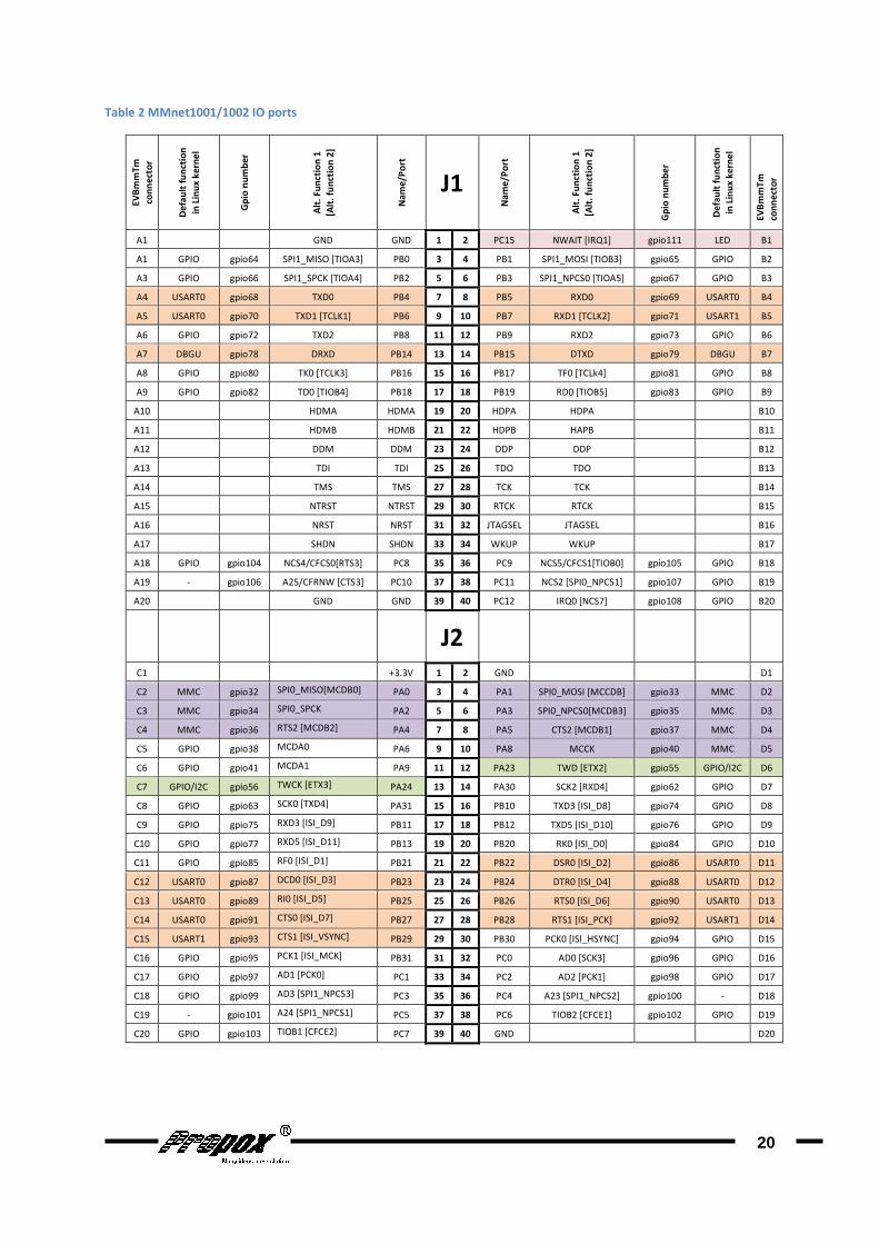
Table 2 MMnet1001/1002 IO ports
EV
Bm
mT
m
con
ne
cto
r
De
fau
lt f
un
ctio
n
in L
inu
x k
ern
el
Gp
io n
um
be
r
Alt
. F
un
ctio
n 1
A1 GND
A1 GPIO gpio64 SPI1_MISO [TIOA3]
A3 GPIO gpio66 SPI1_SPCK [TIOA4]
A4 USART0 gpio68 TXD0
A5 USART0 gpio70 TXD1 [TCLK1]
A6 GPIO gpio72 TXD2
A7 DBGU gpio78 DRXD
A8 GPIO gpio80 TK0 [TCLK3]
A9 GPIO gpio82 TD0 [TIOB4]
A10 HDMA
A11 HDMB
A12 DDM
A13 TDI
A14 TMS
A15 NTRST
A16 NRST
A17 SHDN
A18 GPIO gpio104 NCS4/CFCS0[RTS3]
A19 - gpio106 A25/CFRNW [CTS3]
A20 GND
C1
C2 MMC gpio32 SPI0_MISO[MCDB0]
C3 MMC gpio34 SPI0_SPCK
C4 MMC gpio36 RTS2 [MCDB2]
C5 GPIO gpio38 MCDA0
C6 GPIO gpio41 MCDA1
C7 GPIO/I2C gpio56 TWCK [ETX3]
C8 GPIO gpio63 SCK0 [TXD4]
C9 GPIO gpio75 RXD3 [ISI_D9]
C10 GPIO gpio77 RXD5 [ISI_D11]
C11 GPIO gpio85 RF0 [ISI_D1]
C12 USART0 gpio87 DCD0 [ISI_D3]
C13 USART0 gpio89 RI0 [ISI_D5]
C14 USART0 gpio91 CTS0 [ISI_D7]
C15 USART1 gpio93 CTS1 [ISI_VSYNC]
C16 GPIO gpio95 PCK1 [ISI_MCK]
C17 GPIO gpio97 AD1 [PCK0]
C18 GPIO gpio99 AD3 [SPI1_NPCS3]
C19 - gpio101 A24 [SPI1_NPCS1]
C20 GPIO gpio103 TIOB1 [CFCE2]
Alt
. F
un
ctio
n 1
[Alt
. fu
nct
ion
2]
Na
me
/Po
rt
J1
Na
me
/Po
rt
Alt
. F
un
ctio
n 1
[Alt
. fu
nct
ion
2]
GND GND 1 2 PC15 NWAIT [IRQ1]
SPI1_MISO [TIOA3] PB0 3 4 PB1 SPI1_MOSI [TIOB3]
SPI1_SPCK [TIOA4] PB2 5 6 PB3 SPI1_NPCS0 [TIOA5]
TXD0 PB4 7 8 PB5 RXD0
TXD1 [TCLK1] PB6 9 10 PB7 RXD1 [TCLK2]
TXD2 PB8 11 12 PB9 RXD2
DRXD PB14 13 14 PB15 DTXD
TK0 [TCLK3] PB16 15 16 PB17 TF0 [TCLk4]
TD0 [TIOB4] PB18 17 18 PB19 RD0 [TIOB5]
HDMA HDMA 19 20 HDPA HDPA
HDMB HDMB 21 22 HDPB HAPB
DDM DDM 23 24 DDP DDP
TDI TDI 25 26 TDO TDO
TMS TMS 27 28 TCK TCK
NTRST NTRST 29 30 RTCK RTCK
NRST NRST 31 32 JTAGSEL JTAGSEL
SHDN SHDN 33 34 WKUP WKUP
NCS4/CFCS0[RTS3] PC8 35 36 PC9 NCS5/CFCS1[TIOB0]
A25/CFRNW [CTS3] PC10 37 38 PC11 NCS2 [SPI0_NPCS1]
GND GND 39 40 PC12 IRQ0 [NCS7]
J2
+3.3V 1 2 GND
SPI0_MISO[MCDB0] PA0 3 4 PA1 SPI0_MOSI [MCCDB]
SPI0_SPCK PA2 5 6 PA3 SPI0_NPCS0[MCDB3]
RTS2 [MCDB2] PA4 7 8 PA5 CTS2 [MCDB1]
PA6 9 10 PA8 MCCK
PA9 11 12 PA23 TWD [ETX2]
TWCK [ETX3] PA24 13 14 PA30 SCK2 [RXD4]
SCK0 [TXD4] PA31 15 16 PB10 TXD3 [ISI_D8]
RXD3 [ISI_D9] PB11 17 18 PB12 TXD5 [ISI_D10]
RXD5 [ISI_D11] PB13 19 20 PB20 RK0 [ISI_D0]
RF0 [ISI_D1] PB21 21 22 PB22 DSR0 [ISI_D2]
DCD0 [ISI_D3] PB23 23 24 PB24 DTR0 [ISI_D4]
RI0 [ISI_D5] PB25 25 26 PB26 RTS0 [ISI_D6]
CTS0 [ISI_D7] PB27 27 28 PB28 RTS1 [ISI_PCK]
CTS1 [ISI_VSYNC] PB29 29 30 PB30 PCK0 [ISI_HSYNC]
PCK1 [ISI_MCK] PB31 31 32 PC0 AD0 [SCK3]
AD1 [PCK0] PC1 33 34 PC2 AD2 [PCK1]
[SPI1_NPCS3] PC3 35 36 PC4 A23 [SPI1_NPCS2]
A24 [SPI1_NPCS1] PC5 37 38 PC6 TIOB2 [CFCE1]
TIOB1 [CFCE2] PC7 39 40 GND
20
Gp
io n
um
be
r
De
fau
lt f
un
ctio
n
in L
inu
x k
ern
el
EV
Bm
mT
m
con
ne
cto
r
gpio111 LED B1
gpio65 GPIO B2
gpio67 GPIO B3
gpio69 USART0 B4
gpio71 USART1 B5
gpio73 GPIO B6
gpio79 DBGU B7
gpio81 GPIO B8
gpio83 GPIO B9
B10
B11
B12
B13
B14
B15
B16
B17
gpio105 GPIO B18
gpio107 GPIO B19
gpio108 GPIO B20
D1
gpio33 MMC D2
gpio35 MMC D3
gpio37 MMC D4
gpio40 MMC D5
gpio55 GPIO/I2C D6
gpio62 GPIO D7
gpio74 GPIO D8
gpio76 GPIO D9
gpio84 GPIO D10
gpio86 USART0 D11
gpio88 USART0 D12
gpio90 USART0 D13
gpio92 USART1 D14
gpio94 GPIO D15
gpio96 GPIO D16
gpio98 GPIO D17
gpio100 - D18
gpio102 GPIO D19
D20
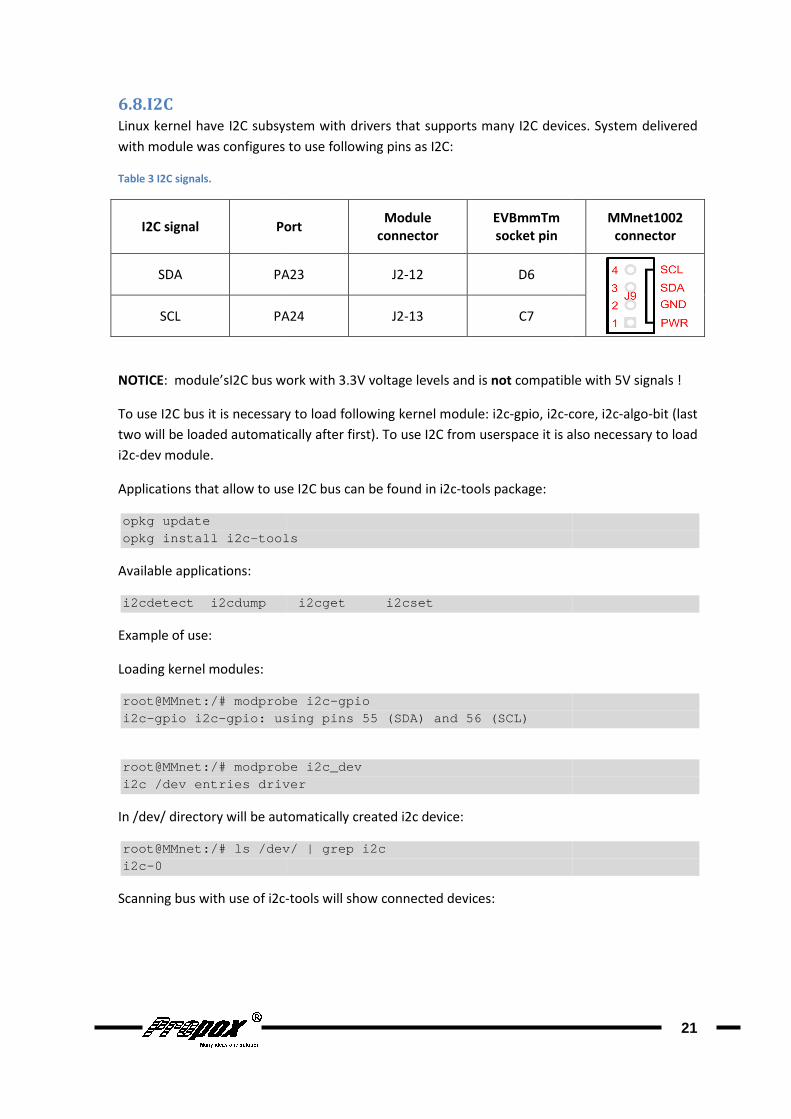
6.8. I2C
Linux kernel have I2C subsystem with
with module was configures to use following pins as I2C
Table 3 I2C signals.
I2C signal Port
SDA PA23
SCL PA24
NOTICE: module’sI2C bus work with 3.3V voltage levels and is
To use I2C bus it is necessary to load following kernel module
two will be loaded automatically
i2c-dev module.
Applications that allow to use I2C bus can be found in
opkg update opkg install i2c- tools
Available applications:
i2cdetect i2cdump i2cget
Example of use:
Loading kernel modules:
root@MMnet:/# modprobe i2ci2c-gpio i2c- gpio: using pins 55 (SDA) and 56 (SCL)
root@MMnet:/# modprobe i2c_devi2c /dev entries driver
In /dev/ directory will be automatically created i2c device
root@MMnet:/# ls /dev/ | grep i2ci2c-0
Scanning bus with use of i2c-
Linux kernel have I2C subsystem with drivers that supports many I2C devices. System delivered
with module was configures to use following pins as I2C:
Port Module
connector
EVBmmTm
socket pin
PA23 J2-12 D6
PA24 J2-13 C7
module’sI2C bus work with 3.3V voltage levels and is not compatible with 5V signals
To use I2C bus it is necessary to load following kernel module: i2c-gpio, i2c-core, i2c
two will be loaded automatically after first). To use I2C from userspace it is also necessary to load
Applications that allow to use I2C bus can be found in i2c-tools package:
tools
i2cdetect i2cdump i2cget i2cset
root@MMnet:/# modprobe i2c -gpio gpio: using pins 55 (SDA) and 56 (SCL)
root@MMnet:/# modprobe i2c_dev i2c /dev entries driver
directory will be automatically created i2c device:
et:/# ls /dev/ | grep i2c
-tools will show connected devices:
21
drivers that supports many I2C devices. System delivered
MMnet1002
connector
compatible with 5V signals !
core, i2c-algo-bit (last
To use I2C from userspace it is also necessary to load

root@MMnet:/# i2cdetect 0 1 2 3 4 5 6 7 8 9 a b c d e f00: -- -- --10: -- -- -- -- -- --20: -- -- -- -- -- --30: -- -- -- -- -- --40: -- -- -- -- -- --50: 50 51 52 53 -- --60: -- -- -- -- -- --70: -- -- -- -- -- --
More information about I2C subsystem can be found in kernel
directory.
6.9. SPI
SPI subsystem documentation and sample software can be found in kernel sources in
Documentation/spi directory
available SPI buses. To configure this, it is necessary to modify file
arch/arm/mach-at91 dirctory in kernel sources and recompile kernel
SPI0 bus use the same gpio pins as
6.10. RTC
Hardware RTC clock is controlled with
time type in console:
root@MMnet:/# hwclock
System time can be set with
root@MMnet:/# date 2009.04.23Thu Apr 23 12:18:00 UTC 2009
root@MMnet:/# i2cdetect -y 0 0 1 2 3 4 5 6 7 8 9 a b c d e f
-- -- -- -- -- -- -- -- -- -- -- -- -- -- -- -- -- -- -- -- -- -- -- -- -- -- -- -- -- -- -- -- -- -- -- -- -- -- -- -- -- -- -- -- -- -- -- -- 49 -- -- -- -- -- -- -- -- -- -- -- -- -- -- -- -- -- -- -- -- 68 -- -- -- -- -- -- -- -- -- --
More information about I2C subsystem can be found in kernel sources in
SPI subsystem documentation and sample software can be found in kernel sources in
directory. Kernel shipped with modules was not configured to use any of 2
available SPI buses. To configure this, it is necessary to modify file board
dirctory in kernel sources and recompile kernel. It should be noted that
SPI0 bus use the same gpio pins as MMC.
Hardware RTC clock is controlled with “hwclock” command. To configure it and set it to system
root@MMnet:/# hwclock –w
System time can be set with “date” command, for example:
root@MMnet:/# date 2009.04.23 -12:18:00 Thu Apr 23 12:18:00 UTC 2009
22
in Documentation/i2c
SPI subsystem documentation and sample software can be found in kernel sources in
Kernel shipped with modules was not configured to use any of 2
board-mmnet1000.c in
hould be noted that
command. To configure it and set it to system

7. Software Development Kit and example applicationsSoftware intended for module have to be compiled on PC computer with Linux system installed
delivered with module contain
i686.tar.bz2 archive.
To make cross-compiler visible in system it should be added to path
export PATH=$PATH:/path/to/i686/staging_dir /toolchain
Where “/path/to/” should be replaced with actual path to directory unpacked from
archive.
Software development kit is based on
• gcc 4.1.2
• uClibc 0.9.29
• gdb 6.3
CD also contain example software. At the moment are
• led-blink – program that
• user-led-blink – program
• spidev_test – program that show how to use SPI bus
• as programs that show how to use I2C bus
http://www.lm-sensors.org/
• programming guide and sample software for Linux serial ports can be found in document
„Serial Programming Guide for POSIX Operating Systems”
http://www.easysw.com/~mike/serial/serial.html
To compile led-blink program:
arm-linux-uclibc- gcc led
Generated ARM executable file should be copied to module
necessary to set executable mode for file
root@MMnet:/# tftp - g root@MMnet:/# chmod +x ledroot@MMnet:/# ./led- blink Exporting gpio 103 ...OKSetting direction of gpio Press Ctrl+C to exit. Setting output value tSetting output value to 1Setting output value to 0Setting output value to 1
Software Development Kit and example applications Software intended for module have to be compiled on PC computer with Linux system installed
delivered with module contain cross-compiler, it can be found in OpenWrt
compiler visible in system it should be added to path:
export PATH=$PATH:/path/to/ OpenWrt-SDK-at91-for-Linux-/toolchain -arm_gcc4.1.2/bin
should be replaced with actual path to directory unpacked from
Software development kit is based on:
CD also contain example software. At the moment are available:
program that blink LED at selected port with selected frequency
program that blink USR LED with selected frequency
program that show how to use SPI bus
as programs that show how to use I2C bus i2c-tools and lm-sensors sources can be used
sensors.org/
programming guide and sample software for Linux serial ports can be found in document
„Serial Programming Guide for POSIX Operating Systems”
http://www.easysw.com/~mike/serial/serial.html
gcc led -blink.c -o led-blink
Generated ARM executable file should be copied to module. According to copy method, it may be
executable mode for file:
g -r led-blink 192.168.1.20 root@MMnet:/# chmod +x led -blink
blink 103 500 ...OK
Setting direction of gpio 103 to output...OK
Press Ctrl+C to exit.
Setting output value t o 0 Setting output value to 1 Setting output value to 0 Setting output value to 1
23
Software intended for module have to be compiled on PC computer with Linux system installed. CD
OpenWrt-SDK-at91-for-Linux-
should be replaced with actual path to directory unpacked from OpenWrt-SDK
at selected port with selected frequency
sources can be used:
programming guide and sample software for Linux serial ports can be found in document
„Serial Programming Guide for POSIX Operating Systems”:
According to copy method, it may be
8. System compilation
8.1. AT91Boot compilation
AT91Boot bootloader sources, adapted for MMnet1001/1002 modules
/sources/Bootstrap-v1.10-MMnet1000.tar.gz
board/MMnet1000/nandflash
make CROSS_COMPILE=arm
8.2. U-Boot-a compilation
U-Boot bootloader sources, adapted for MMnet1001/1002 modules, are on CD in
boot-2009.01-MMnet1000.tar.gz
modified to our modules needs
recompile U-Boot unpack sources and type:
make CROSS_COMPILE=arm
Generated u-boot.bin file can be used to fl
8.3. Linux kernel compilation
Linux kernel sources, adapted for MMnet1001/1002 modules, are on CD in
2.6.29.3-MMnet1000.tar.gz
boards:
make ARCH=arm CROSS_COMPILE=arm
To configure kernel:
make ARCH=arm CROSS_COMPILE=arm
To compile kernel:
make ARCH=arm CROSS_COMPILE=arm
After compiling in arch/arm/boot
module.
To compile kernel modules:
make ARCH=arm CROSS_COMPILE=arm
To install kernel modules:
make ARCH=arm CROSS_COMPILE=armINSTALL_MOD_PATH=/path/to/my/rootfs modules_install
Where /path/to/my/rootfs is a path where kernel module will be copied
to module or used to create new filesystem image
File specific to MMnet1000 modules and containing boars initialization code is in
arch/arm/mach-at91/board-
System compilation
compilation
AT91Boot bootloader sources, adapted for MMnet1001/1002 modules
MMnet1000.tar.gz archive. To compile it
board/MMnet1000/nandflash directory:
make CROSS_COMPILE=arm-linux-uclibc-
compilation
Boot bootloader sources, adapted for MMnet1001/1002 modules, are on CD in
MMnet1000.tar.gz archive. Configuration for board at91sam9260ek
modified to our modules needs. Configuration file is in include/configs/at91sam9260ek.h
Boot unpack sources and type:
make CROSS_COMPILE=arm-linux-uclibc-
file can be used to flash module.
Linux kernel compilation
Linux kernel sources, adapted for MMnet1001/1002 modules, are on CD in
archive. After unpacking it should be configured for MMnet1000
CROSS_COMPILE=arm-linux-uclibc- mmnet1000_defconfig
make ARCH=arm CROSS_COMPILE=arm-linux-uclibc- menuconfig
make ARCH=arm CROSS_COMPILE=arm-linux-uclibc- uImage
arch/arm/boot directory uImage file should appear. It can be used to flash
make ARCH=arm CROSS_COMPILE=arm-linux-uclibc- modules
make ARCH=arm CROSS_COMPILE=arm-linux-uclibc- INSTALL_MOD_PATH=/path/to/my/rootfs modules_install
is a path where kernel module will be copied. They should be copied
to module or used to create new filesystem image.
File specific to MMnet1000 modules and containing boars initialization code is in
-mmnet1000.c file.
24
AT91Boot bootloader sources, adapted for MMnet1001/1002 modules, are on CD in
compile it type in
Boot bootloader sources, adapted for MMnet1001/1002 modules, are on CD in /sources/u-
at91sam9260ek was used and
include/configs/at91sam9260ek.h file. To
Linux kernel sources, adapted for MMnet1001/1002 modules, are on CD in /sources/linux-
After unpacking it should be configured for MMnet1000
mmnet1000_defconfig
e should appear. It can be used to flash
They should be copied
File specific to MMnet1000 modules and containing boars initialization code is in

8.4. OpenWrt compilation
OpenWrt system delivered with module was compiled from SVN revision 13340. Sources are
included on CD.
Because OpenWrt build system
format. UBI image should be prepared manually from this archive
More information can be found in OpenWrt documentation:
http://kamikaze.openwrt.org/docs/openwrt.html#x1
8.5. UBI and UBIFS images preparation
Two directories are needed
containing files for root filesystem
First create UBIFS images:
mkfs.ubifs - r ./storage storage.ubifs
mkfs.ubifs - r ./rootfs rootfs.ubifs
Then UBI image containing volumes with UBIFS filesystems
ubinize - o MMnet1000
(where ubinize.cfg is configuration file, it can be found on CD and in attachment in this
document). Created MMnet1000
to Flash memory.
Documentation of mtd subsystem, UB
utils can be found at: http://www.linux
compilation
OpenWrt system delivered with module was compiled from SVN revision 13340. Sources are
build system can’t generate UBI images, tar.gz should be
format. UBI image should be prepared manually from this archive.
can be found in OpenWrt documentation:
http://kamikaze.openwrt.org/docs/openwrt.html#x1-390002
UBI and UBIFS images preparation
Two directories are needed : ./storage (empty directory for „storage” volume
containing files for root filesystem. PC computer should also have mtd-utils
r ./storage -m 2048 -e 258048 -c 4096 – o MMnet1000
r ./rootfs -m 2048 -e 258048 -c 4096 -o M Mnet1000
Then UBI image containing volumes with UBIFS filesystems:
o MMnet1000 -OpenWrt.ubi -m 2048 - p 256KiB ubinize.cfg
is configuration file, it can be found on CD and in attachment in this
MMnet1000-OpenWrt.ubi file contain UBI image which can be programmed
Documentation of mtd subsystem, UBI layer, UBIFS file system and associated with them mtd
http://www.linux-mtd.infradead.org/
25
OpenWrt system delivered with module was compiled from SVN revision 13340. Sources are
UBI images, tar.gz should be selected as output
empty directory for „storage” volume) and ./rootfs
utils packane installed.
o MMnet1000 -
Mnet1000 -OpenWrt-
p 256KiB ubinize.cfg
is configuration file, it can be found on CD and in attachment in this
file contain UBI image which can be programmed
I layer, UBIFS file system and associated with them mtd-

9. FAQ
9.1. During system boot messages
appear. Is this normal
It is normal. NAND Flash memories can have bad blocks even when they are new. Bad blocks
count will increase during memory lifetime but will not exceeds 100 (it is guaranteed by memory
manufacturer). UBU layer and UBIFS filesystem used in module gu
loss.
9.2. microSD do not work with MMnet1002
Check if your module have R44 resistor mounted, if it has, unsolder it. Some of first modules was
shipped with this resistor mounted
During system boot messages „Bad eraseblock 1843 at 0x1ccc0000”
normal?
It is normal. NAND Flash memories can have bad blocks even when they are new. Bad blocks
count will increase during memory lifetime but will not exceeds 100 (it is guaranteed by memory
UBU layer and UBIFS filesystem used in module guarantee protection from data
do not work with MMnet1002
Check if your module have R44 resistor mounted, if it has, unsolder it. Some of first modules was
shipped with this resistor mounted.
26
„Bad eraseblock 1843 at 0x1ccc0000”
It is normal. NAND Flash memories can have bad blocks even when they are new. Bad blocks
count will increase during memory lifetime but will not exceeds 100 (it is guaranteed by memory
arantee protection from data
Check if your module have R44 resistor mounted, if it has, unsolder it. Some of first modules was
10. Useful links http://kernel.org/
http://www.denx.de/wiki/U
http://openwrt.org/
http://www.linux4sam.org
http://www.at91.com
http://www.network-theory.co.uk/gcc/intro/
http://www.linux-mtd.infradead.org/
http://www.linux-usb.org/
http://www.linux-usb.org/gadget/
http://elinux.org
11. License, warranty and technical support
Most of software delivered with module has GNU GPL
software sources or in its documentation.
Software delivered with module is free, open source software. It is delivered “as is”, with hope that
will be useful, but without any warranty. Propox company does not ta
software.
We can provide only basic technical support in matters closely related to our MMnet1001/1002
modules. We do not provide support for general Linux matters nor for delivered by us software
which is not written by us.
Technical support is provided only by e
http://www.denx.de/wiki/U-Boot/WebHome
http://www.linux4sam.org
theory.co.uk/gcc/intro/
mtd.infradead.org/
usb.org/
usb.org/gadget/
, warranty and technical support
Most of software delivered with module has GNU GPL license or similar. Details can be found in
software sources or in its documentation.
Software delivered with module is free, open source software. It is delivered “as is”, with hope that
will be useful, but without any warranty. Propox company does not take any responsibility for this
We can provide only basic technical support in matters closely related to our MMnet1001/1002
modules. We do not provide support for general Linux matters nor for delivered by us software
Technical support is provided only by e-mail. Please send questions to: [email protected]
27
or similar. Details can be found in
Software delivered with module is free, open source software. It is delivered “as is”, with hope that
ke any responsibility for this
We can provide only basic technical support in matters closely related to our MMnet1001/1002
modules. We do not provide support for general Linux matters nor for delivered by us software
12. Attachments
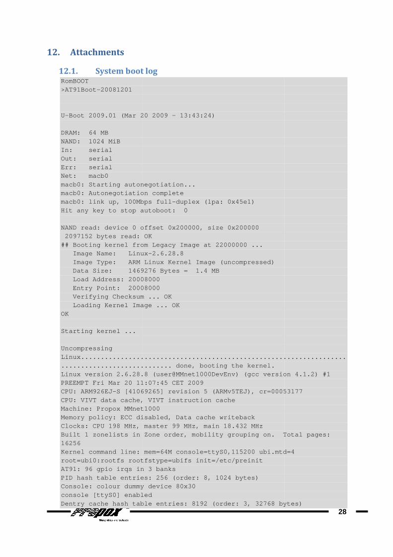
12.1. System boot logRomBOOT >AT91Boot-20081201 U- Boot 2009.01 (Mar 20 2009 DRAM: 64 MB NAND: 1024 MiB In: serial Out: serial Err: serial Net: macb0 macb0: Starting autonegotiation...macb0: Autonegotiation completemacb0: link up, 100Mbps fullHit any key to stop autoboot: 0 NAND read: device 0 offset 0x200000, size 2097152 bytes read: OK## Booting kernel from Legacy Image at 22000000 ... Image Name: Linux Image Type: ARM Linux Kernel Image (uncompressed) Data Size: 1469276 Bytes = 1.4 MB Load Address: 20008000 Entry Point: 20008000 Verifying Checksum ... OK Loading Kernel Image ... OKOK Starting kernel ... Uncompressing Linux.............................................. ................................................. done, booting the kern el.Linux version 2.6.28.PREEMPT Fri Mar 20 11:07:45 CET 2009CPU: ARM926EJ- S [41069265] revision 5 (ARMv5TEJ), cr=00053177CPU: VIVT data cache, VIVT instruction cacheMachine: Propox MMnet1000Memory policy: ECC disabled, Data cachClocks: CPU 198 MHz, master 99 MHz, main 18.432 MHzBuilt 1 zonelists in Zone order, mobility grouping on. Total pages: 16256 Kernel command line: mem=64M console=ttyS0,115200 u bi.mtd=4 root=ubi0:rootfs rootfstype=ubifs init=/etc/preinitAT91: 96 gpio irqs in 3 banksPID hash table entries: 256 (order: 8, 1024 bytes)Console: colour dummy device 80x30console [ttyS0] enabledDentry cache hash table entries: 8192 (order: 3, 32 768 bytes)
System boot log
Boot 2009.01 (Mar 20 2009 - 13:43:24)
macb0: Starting autonegotiation... macb0: Autonegotiation complete macb0: link up, 100Mbps full -duplex (lpa: 0x45e1) Hit any key to stop autoboot: 0
NAND read: device 0 offset 0x200000, size 0x200000 2097152 bytes read: OK
## Booting kernel from Legacy Image at 22000000 ... Image Name: Linux -2.6.28.8 Image Type: ARM Linux Kernel Image (uncompressed) Data Size: 1469276 Bytes = 1.4 MB Load Address: 20008000
20008000 Verifying Checksum ... OK Loading Kernel Image ... OK
Linux.............................................. ................................................. done, booting the kern el. Linux version 2.6.28. 8 (user@MMnet1000DevEnv) (gcc version 4.1.2) #1 PREEMPT Fri Mar 20 11:07:45 CET 2009
S [41069265] revision 5 (ARMv5TEJ), cr=00053177CPU: VIVT data cache, VIVT instruction cache Machine: Propox MMnet1000 Memory policy: ECC disabled, Data cach e writeback Clocks: CPU 198 MHz, master 99 MHz, main 18.432 MHz Built 1 zonelists in Zone order, mobility grouping on. Total pages:
Kernel command line: mem=64M console=ttyS0,115200 u bi.mtd=4 root=ubi0:rootfs rootfstype=ubifs init=/etc/preinit
96 gpio irqs in 3 banks PID hash table entries: 256 (order: 8, 1024 bytes) Console: colour dummy device 80x30 console [ttyS0] enabled Dentry cache hash table entries: 8192 (order: 3, 32 768 bytes)
28
Linux.............................................. .....................
8 (user@MMnet1000DevEnv) (gcc version 4.1.2) #1
S [41069265] revision 5 (ARMv5TEJ), cr=00053177
Built 1 zonelists in Zone order, mobility grouping on. Total pages:
Kernel command line: mem=64M console=ttyS0,115200 u bi.mtd=4
Dentry cache hash table entries: 8192 (order: 3, 32 768 bytes)
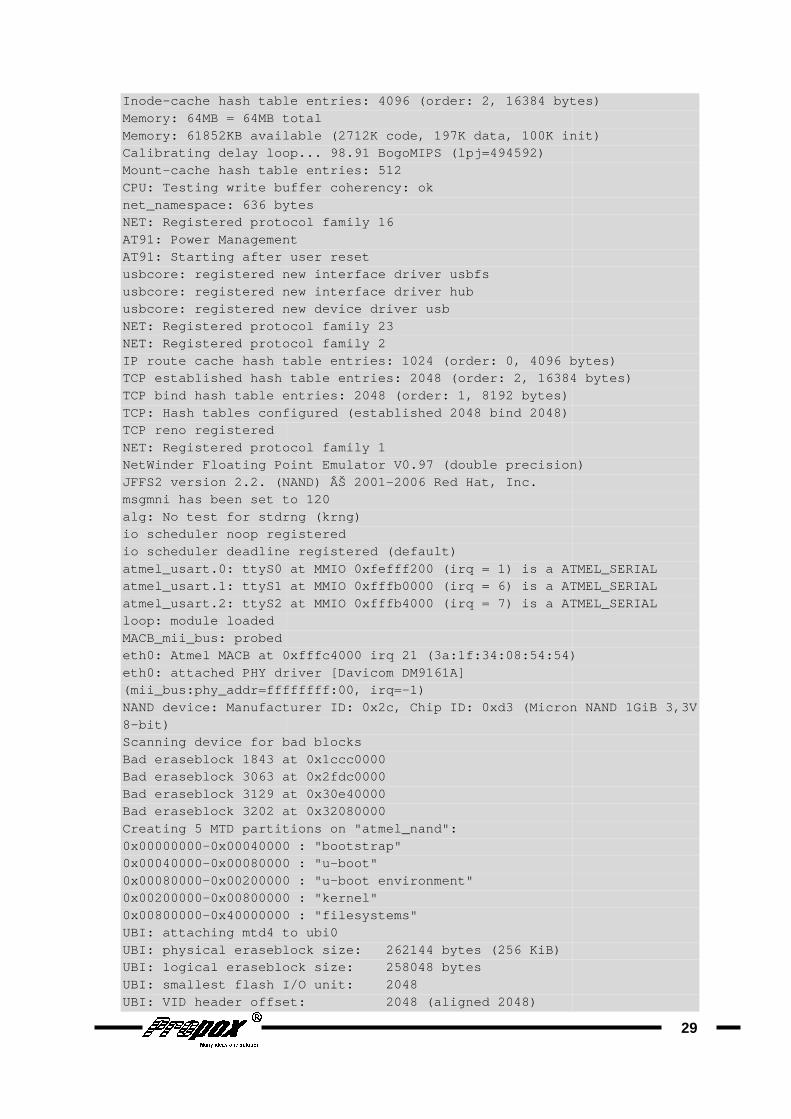
Inode- cache hash table entries: 4096 (order: 2, 16384 byt esMemory: 64MB = 64MB totalMemory: 61852KB available (2712K code, 197K data, 1 00K init)Calibrating delay loop... 98.91 BogoMIPS (lpj=49459 2)Mount- cache hash table entries: 512CPU: Testing write buffer coherency: oknet_namespace: 636 bytesNET: Registe red protocol family 16AT91: Power ManagementAT91: Starting after user resetusbcore: registered new interface driver usbfsusbcore: registered new interface driver hubusbcore: registered new device driver usbNET: Registered protocol family 23NET: Regi stered protocol family 2IP route cache hash table entries: 1024 (order: 0, 4096 bytes)TCP established hash table entries: 2048 (order: 2, 16384 bytes)TCP bind hash table entries: 2048 (order: 1, 8192 b ytes)TCP: Hash tables configured (established 2048 TCP reno registered NET: Registered protocol family 1NetWinder Floating Point Emulator V0.97 (double pre cision)JFFS2 version 2.2. (NAND) Š 2001msgmni has been set to 120alg: No test for stdrng (krng)io scheduler noop registeredio scheduler deadline registered (default)atmel_usart.0: ttyS0 at MMIO 0xfefff200 (irq = 1) i s a ATMEL_SERIALatmel_usart.1: ttyS1 at MMIO 0xfffb0000 (irq = 6) i s a ATMEL_SERIALatmel_usart.2: ttyS2 at MMIO 0xfffb4000 (irq = 7) i s a ATMEL_SERIAloop: module loaded MACB_mii_bus: probed eth0: Atmel MACB at 0xfffc4000 irq 21 (3a:1f:34:08: 54:54)eth0: attached PHY driver [Davicom DM9161A] (mii_bus:phy_addr=ffffffff:00, irq=NAND device: Manufacturer ID: 0x2c, Chip ID: 0xd3 ( Micron NAND 1GiB 3,3V8-bit) Scanning device for bad blocksBad eraseblock 1843 at 0x1ccc0000Bad eraseblock 3063 at 0x2fdc0000Bad eraseblock 3129 at 0x30e40000Bad eraseblock 3202 at 0x32080000Creating 5 MTD partitions on "atmel_nand":0x00000000- 0x00040000 : "bootstrap"0x00040000- 0x00080000 : "u0x00080000- 0x00200000 : "u0x00200000- 0x00800000 : "kernel"0x00800000- 0x40000000 : "filesystems"UBI: attaching mtd4 to ubi0UBI: physical eraseblock size: 262144 bytes (256 KiB)UBI: logical eraseblock sUBI: smallest flash I/O unit: 2048UBI: VID header offset: 2048 (aligned 2048 )
cache hash table entries: 4096 (order: 2, 16384 byt esMemory: 64MB = 64MB total Memory: 61852KB available (2712K code, 197K data, 1 00K init)Calibrating delay loop... 98.91 BogoMIPS (lpj=49459 2)
cache hash table entries: 512 CPU: Testing write buffer coherency: ok net_namespace: 636 bytes
red protocol family 16 AT91: Power Management AT91: Starting after user reset usbcore: registered new interface driver usbfs usbcore: registered new interface driver hub usbcore: registered new device driver usb NET: Registered protocol family 23
stered protocol family 2 IP route cache hash table entries: 1024 (order: 0, 4096 bytes)TCP established hash table entries: 2048 (order: 2, 16384 bytes)TCP bind hash table entries: 2048 (order: 1, 8192 b ytes) TCP: Hash tables configured (established 2048 bind 2048)
NET: Registered protocol family 1 NetWinder Floating Point Emulator V0.97 (double pre cision)JFFS2 version 2.2. (NAND) Š 2001 -2006 Red Hat, Inc. msgmni has been set to 120 alg: No test for stdrng (krng)
registered io scheduler deadline registered (default) atmel_usart.0: ttyS0 at MMIO 0xfefff200 (irq = 1) i s a ATMEL_SERIALatmel_usart.1: ttyS1 at MMIO 0xfffb0000 (irq = 6) i s a ATMEL_SERIALatmel_usart.2: ttyS2 at MMIO 0xfffb4000 (irq = 7) i s a ATMEL_SERIA
eth0: Atmel MACB at 0xfffc4000 irq 21 (3a:1f:34:08: 54:54)eth0: attached PHY driver [Davicom DM9161A] (mii_bus:phy_addr=ffffffff:00, irq= -1) NAND device: Manufacturer ID: 0x2c, Chip ID: 0xd3 ( Micron NAND 1GiB 3,3V
Scanning device for bad blocks Bad eraseblock 1843 at 0x1ccc0000 Bad eraseblock 3063 at 0x2fdc0000 Bad eraseblock 3129 at 0x30e40000 Bad eraseblock 3202 at 0x32080000 Creating 5 MTD partitions on "atmel_nand":
0x00040000 : "bootstrap" 0x00080000 : "u -boot" 0x00200000 : "u -boot environment" 0x00800000 : "kernel" 0x40000000 : "filesystems"
UBI: attaching mtd4 to ubi0 UBI: physical eraseblock size: 262144 bytes (256 KiB) UBI: logical eraseblock s ize: 258048 bytes UBI: smallest flash I/O unit: 2048 UBI: VID header offset: 2048 (aligned 2048 )
29
cache hash table entries: 4096 (order: 2, 16384 byt es )
Memory: 61852KB available (2712K code, 197K data, 1 00K init)
IP route cache hash table entries: 1024 (order: 0, 4096 bytes) TCP established hash table entries: 2048 (order: 2, 16384 bytes)
NetWinder Floating Point Emulator V0.97 (double pre cision)
atmel_usart.0: ttyS0 at MMIO 0xfefff200 (irq = 1) i s a ATMEL_SERIAL atmel_usart.1: ttyS1 at MMIO 0xfffb0000 (irq = 6) i s a ATMEL_SERIAL atmel_usart.2: ttyS2 at MMIO 0xfffb4000 (irq = 7) i s a ATMEL_SERIA L
eth0: Atmel MACB at 0xfffc4000 irq 21 (3a:1f:34:08: 54:54)
NAND device: Manufacturer ID: 0x2c, Chip ID: 0xd3 ( Micron NAND 1GiB 3,3V
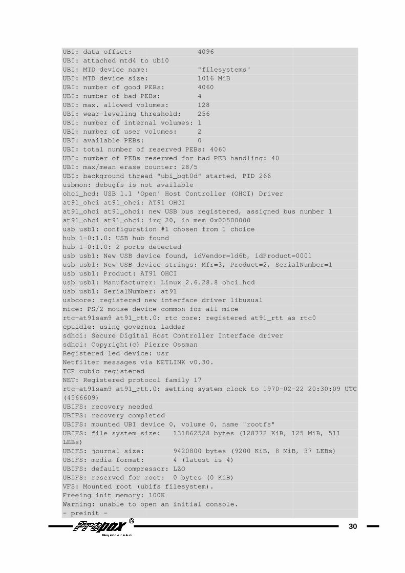
UBI: data offset: 4096UBI: attached mtd4 to ubi0UBI: MTD device name: "filesystems"UBI: MTD device size: UBI: number of good PEBs: 4060UBI: number of bad PEBs: 4UBI: max. allowed volumes: 128UBI: wear- leveling threshold: 256UBI: number of internal volumes: 1UBI: number of user volumes: 2UBI: available PEBs: UBI: total number of reserved PEBs: 4060UBI: number of PEBs reserved for bad PEB handling: 40UBI: max/mean erase counter: 28/5UBI: background thread "ubi_bgt0d" started, PID 266usbmon: debugfs is not availableohci_hcd: USB 1.1 'Open' Host at91_ohci at91_ohci: AT91 OHCIat91_ohci at91_ohci: new USB bus registered, assign ed bus number 1at91_ohci at91_ohci: irq 20, io mem 0x00500000usb usb1: configuration #1 chosen from 1 choicehub 1- 0:1.0: USB hub foundhub 1-0:1.0 : 2 ports detectedusb usb1: New USB device found, idVendor=1d6b, idPr oduct=0001usb usb1: New USB device strings: Mfr=3, Product=2, SerialNumber=1usb usb1: Product: AT91 OHCIusb usb1: Manufacturer: Linux 2.6.28.8 ohci_hcdusb usb1: SerialNumber: at91us bcore: registered new interface driver libusualmice: PS/2 mouse device common for all micertc- at91sam9 at91_rtt.0: rtc core: registered at91_rtt as rtc0cpuidle: using governor laddersdhci: Secure Digital Host Controller Interface dri versdhci: Copyright(c) Pierre OssmanRegistered led device: usrNetfilter messages via NETLINK v0.30.TCP cubic registered NET: Registered protocol family 17rtc- at91sam9 at91_rtt.0: setting system clock to 1970(4566609) UBIFS: recovery neededUBIFS: recovery completedUBIFS: mounted UBI device 0, volume 0, name "rootfs "UBIFS: file system size: 131862528 bytes (128772 KiB, 125 MiB, 511 LEBs) UBIFS: journal size: 9420800 bytes (9200 KiB, 8 MiB, 37 LEBs)UBIFS: media format: 4 (latestUBIFS: default compressor: LZOUBIFS: reserved for root: 0 bytes (0 KiB)VFS: Mounted root (ubifs filesystem).Freeing init memory: 100KWarning: unable to open an initial console.- preinit -
UBI: data offset: 4096 UBI: attached mtd4 to ubi0 UBI: MTD device name: "filesystems" UBI: MTD device size: 1016 MiB UBI: number of good PEBs: 4060 UBI: number of bad PEBs: 4 UBI: max. allowed volumes: 128
leveling threshold: 256 UBI: number of internal volumes: 1 UBI: number of user volumes: 2 UBI: available PEBs: 0 UBI: total number of reserved PEBs: 4060 UBI: number of PEBs reserved for bad PEB handling: 40 UBI: max/mean erase counter: 28/5 UBI: background thread "ubi_bgt0d" started, PID 266 usbmon: debugfs is not available ohci_hcd: USB 1.1 'Open' Host Controller (OHCI) Driver at91_ohci at91_ohci: AT91 OHCI at91_ohci at91_ohci: new USB bus registered, assign ed bus number 1at91_ohci at91_ohci: irq 20, io mem 0x00500000 usb usb1: configuration #1 chosen from 1 choice
0:1.0: USB hub found : 2 ports detected
usb usb1: New USB device found, idVendor=1d6b, idPr oduct=0001usb usb1: New USB device strings: Mfr=3, Product=2, SerialNumber=1usb usb1: Product: AT91 OHCI usb usb1: Manufacturer: Linux 2.6.28.8 ohci_hcd usb usb1: SerialNumber: at91
bcore: registered new interface driver libusual mice: PS/2 mouse device common for all mice
at91sam9 at91_rtt.0: rtc core: registered at91_rtt as rtc0cpuidle: using governor ladder sdhci: Secure Digital Host Controller Interface dri ver
Copyright(c) Pierre Ossman Registered led device: usr Netfilter messages via NETLINK v0.30.
NET: Registered protocol family 17
at91sam9 at91_rtt.0: setting system clock to 1970 -02 -
UBIFS: recovery needed IFS: recovery completed
UBIFS: mounted UBI device 0, volume 0, name "rootfs " UBIFS: file system size: 131862528 bytes (128772 KiB, 125 MiB, 511
UBIFS: journal size: 9420800 bytes (9200 KiB, 8 MiB, 37 LEBs)UBIFS: media format: 4 (latest is 4) UBIFS: default compressor: LZO UBIFS: reserved for root: 0 bytes (0 KiB) VFS: Mounted root (ubifs filesystem). Freeing init memory: 100K Warning: unable to open an initial console.
30
at91_ohci at91_ohci: new USB bus registered, assign ed bus number 1
usb usb1: New USB device found, idVendor=1d6b, idPr oduct=0001 usb usb1: New USB device strings: Mfr=3, Product=2, SerialNumber=1
at91sam9 at91_rtt.0: rtc core: registered at91_rtt as rtc0
- 22 20:30:09 UTC
UBIFS: file system size: 131862528 bytes (128772 KiB, 125 MiB, 511
UBIFS: journal size: 9420800 bytes (9200 KiB, 8 MiB, 37 LEBs)
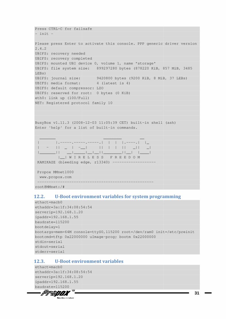
Press CTRL- C for failsafe- init - Please press Enter to activate this console. PPP generic driver versio n 2.4.2 UBIFS: recovery neededUBIFS: recovery completedUBIFS: mounted UBI device 0, volume 1, name "storag e"UBIFS: file system size: 899297280 bytes (878220 KiB, 857 MiB, 3485 LEBs) UBIFS: journal size: 9420800 bytes (9200 KiB, 8 MiB, 37 LEBs )UBIFS: media format: 4 (latest is 4)UBIFS: default compressor: LZOUBIFS: reserved for root: 0 bytes (0 KiB)eth0: link up (100/Full)NET: Registered protocol family 10 BusyBox v1.11.3 (2008Enter 'help' for a list of built _______ ________ __ | |.-----. ----- | - || _ | - __| || | | || _|| _| |_______| | __|_____|__|__||________||__| |____| |__| W I R E L E S S F R E E D O M KAMIKAZE (bleeding edge, r13340) Propox MMnet1000 www.propox.com ---------------------------------------------------root@MMnet:/#
12.2. U-Boot environment variables for system programmingethact=macb0 ethaddr=3a:1f:34:08:54:54serverip=192.168.1.20ipaddr=192.168.1.55 baudrate=115200 bootdelay=1 bootargs=mem=64M console=ttyS0,115200 root=/dev/ram 0 init=/etc/preinitbootcmd=tftp 0x22000000 stdin=serial stdout=serial stderr=serial
12.3. U-Boot environment variablesethact=macb0 ethaddr=3a:1f:34:08:54:54serverip=192.168.1.20ipaddr=192.168.1.55 baudrate=115200
C for failsafe
to activate this console. PPP generic driver versio n
UBIFS: recovery needed UBIFS: recovery completed UBIFS: mounted UBI device 0, volume 1, name "storag e" UBIFS: file system size: 899297280 bytes (878220 KiB, 857 MiB, 3485
size: 9420800 bytes (9200 KiB, 8 MiB, 37 LEBs )UBIFS: media format: 4 (latest is 4) UBIFS: default compressor: LZO UBIFS: reserved for root: 0 bytes (0 KiB) eth0: link up (100/Full) NET: Registered protocol family 10
(2008 -12-03 11:05:39 CET) built- in shell (ash)Enter 'help' for a list of built -in commands.
_______ ________ __ ----- .-----.| | | |.----.| |_
__| || | | || _|| _| | __|_____|__|__||________||__| |____| |__| W I R E L E S S F R E E D O M
KAMIKAZE (bleeding edge, r13340) -------------------
---------------------------------------------------
vironment variables for system programming
ethaddr=3a:1f:34:08:54:54 serverip=192.168.1.20
bootargs=mem=64M console=ttyS0,115200 root=/dev/ram 0 init=/etc/preinitbootcmd=tftp 0x22000000 uImage-prog; bootm 0x22000000
Boot environment variables
ethaddr=3a:1f:34:08:54:54 serverip=192.168.1.20
31
to activate this console. PPP generic driver versio n
UBIFS: file system size: 899297280 bytes (878220 KiB, 857 MiB, 3485
size: 9420800 bytes (9200 KiB, 8 MiB, 37 LEBs )
in shell (ash)
vironment variables for system programming
bootargs=mem=64M console=ttyS0,115200 root=/dev/ram 0 init=/etc/preinit
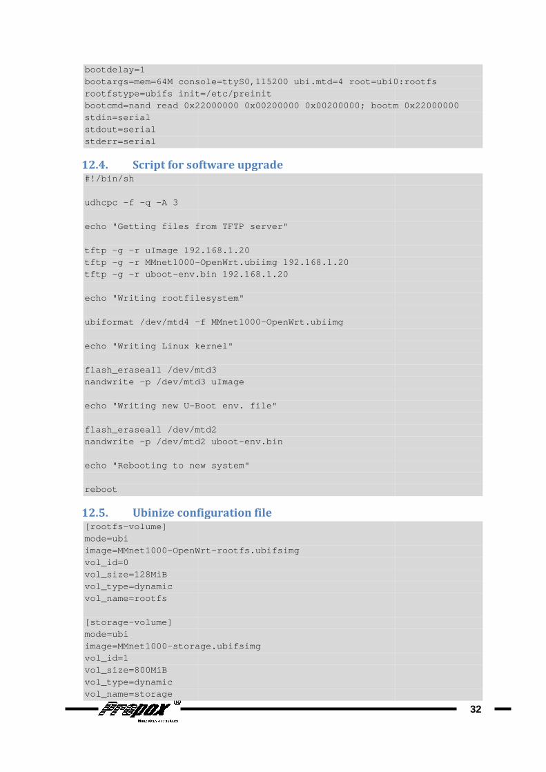
bootdelay=1 bootargs=mem=64M console=ttyS0,115200 rootfstype=ubifs init=/etc/preinitbootcmd=nand read 0x22000000 0x00200000 0x00200000; bootm 0x22000000stdin=serial stdout=serial stderr=serial
12.4. Script for software upgrade#!/bin/sh udhcpc -f -q -A 3 echo " Getting files from tftp -g - r uImage 192.168.1.20tftp -g -r MMnet1000 -tftp -g -r uboot- env.bin 192.168.1.20 echo " Writing rootfilesystem ubiformat /dev/mtd4 - echo " Writing Linux kernel flash_eraseall /dev/mtd3nandwrite - p /dev/mtd3 uImage echo "Writing new U- Boot env. file flash_eraseall /dev/mtd2nandwrite - p /dev/mtd2 uboot echo " Rebooting to new system reboot
12.5. Ubinize configuration file[rootfs-volume] mode=ubi image=MMnet1000- OpenWrtvol_id=0 vol_size=128MiB vol_type=dynamic vol_name=rootfs [storage-volume] mode=ubi image=MMnet1000- storage.ubifsimgvol_id=1 vol_size=800MiB vol_type=dynamic vol_name=storage
bootargs=mem=64M console=ttyS0,115200 ubi.mtd=4 root=ubi0:rootfs rootfstype=ubifs init=/etc/preinit bootcmd=nand read 0x22000000 0x00200000 0x00200000; bootm 0x22000000
Script for software upgrade
Getting files from TFTP server"
r uImage 192.168.1.20 - OpenWrt.ubiimg 192.168.1.20
env.bin 192.168.1.20
Writing rootfilesystem "
- f MMnet1000-OpenWrt.ubiimg
Writing Linux kernel "
/dev/mtd3 p /dev/mtd3 uImage
Boot env. file "
flash_eraseall /dev/mtd2 p /dev/mtd2 uboot -env.bin
Rebooting to new system "
configuration file
OpenWrt -rootfs.ubifsimg
storage.ubifsimg
32
ubi.mtd=4 root=ubi0:rootfs
bootcmd=nand read 0x22000000 0x00200000 0x00200000; bootm 0x22000000
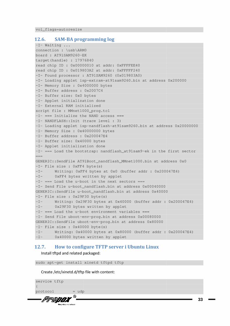
vol_flags=autoresize
12.6. SAM-BA programming log-I- Waiting ... connection : \usb\ ARM0board : AT91SAM9260- EKtarget(handle) : 17976840read chip ID : 0x00000010 at addr: 0xFFFFEE40read chip ID : 0x019803A2 at addr: 0xFFFFF240-I- Found processor : AT91SAM9260 (0x019803A0)-I- Loading applet isp-I- Memory Size : 0x4000000 bytes-I- Buffer address : 0x2007C4-I- Buffer size: 0x0 bytes-I- Applet initialization done-I- External RAM initializedscript file : MMnet1000_prog.tcl-I- === Initialize the NAND access ===-I- NANDFLASH::Init (trace level : 3)-I- Loading applet isp-I- Memory Size : 0x40000000 bytes-I- Buffer address : 0x200047E4-I- Buffer size: 0x40000 bytes-I- Applet initialization -I- === Load the bootstrap: nandflash_at91sam9=== GENERIC::SendFile AT91Boot_nandflash_MMnet1000.bin at address 0x0-I- File size : 0xFF4 byte(s)-I- Writing: 0xFF4 bytes at 0x0 (buffer addr : 0x200047 E4)-I- 0xFF4 bytes writ-I- === Load the u- boot in the next sectors ===-I- Send File u- boot_nandflash.bin at address 0x00040000GENERIC::SendFile u- boot_nandflash.bin at address 0x40000-I- File size : 0x29F30 byte(s)-I- Writing: 0x29F30 bytes at 0x40000 (buffer -I- 0x29F30 bytes written by applet-I- === Load the u- boot environment variables ===-I- Send File uboot- envGENERIC::SendFile uboot-I- File size : 0x40000 byte(s)-I- Wr iting: 0x40000 bytes at 0x80000 (buffer addr : 0x20 0047E4)-I- 0x40000 bytes written by applet
12.7. How to configure TFTP server i Ubuntu Linux
Install tftpd and related packaged
sudo apt- get install xinetd tftpd tftp
Create /etc/xinetd.d/tftp
service tftp { protocol = udp
programming log
ARM0 EK
target(handle) : 17976840 read chip ID : 0x00000010 at addr: 0xFFFFEE40 read chip ID : 0x019803A2 at addr: 0xFFFFF240
Found processor : AT91SAM9260 (0x019803A0) applet isp -extram- at91sam9260.bin at address 0x200000
Memory Size : 0x4000000 bytes Buffer address : 0x2007C4 Buffer size: 0x0 bytes Applet initialization done External RAM initialized
script file : MMnet1000_prog.tcl the NAND access ===
NANDFLASH::Init (trace level : 3) Loading applet isp -nandflash- at91sam9260.bin at address 0x20000000Memory Size : 0x40000000 bytes Buffer address : 0x200047E4 Buffer size: 0x40000 bytes Applet initialization done === Load the bootstrap: nandflash_at91sam9 - ek in the first sector
GENERIC::SendFile AT91Boot_nandflash_MMnet1000.bin at address 0x0File size : 0xFF4 byte(s)
Writing: 0xFF4 bytes at 0x0 (buffer addr : 0x200047 E4)0xFF4 bytes writ ten by applet
boot in the next sectors === boot_nandflash.bin at address 0x00040000
boot_nandflash.bin at address 0x40000File size : 0x29F30 byte(s)
Writing: 0x29F30 bytes at 0x40000 (buffer addr : 0x200047E4)0x29F30 bytes written by applet
boot environment variables === env -prog.bin at address 0x00080000
GENERIC::SendFile uboot -env-prog.bin at address 0x80000 File size : 0x40000 byte(s)
iting: 0x40000 bytes at 0x80000 (buffer addr : 0x20 0047E4)0x40000 bytes written by applet
How to configure TFTP server i Ubuntu Linux
Install tftpd and related packaged:
get install xinetd tftpd tftp
/etc/xinetd.d/tftp file with content:
protocol = udp
33
at91sam9260.bin at address 0x200000
at91sam9260.bin at address 0x20000000
ek in the first sector
GENERIC::SendFile AT91Boot_nandflash_MMnet1000.bin at address 0x0
Writing: 0xFF4 bytes at 0x0 (buffer addr : 0x200047 E4)
boot_nandflash.bin at address 0x40000
addr : 0x200047E4)
iting: 0x40000 bytes at 0x80000 (buffer addr : 0x20 0047E4)

port = 69 socket_type = dgramwait = yesuser = nobodyserver = /usr/sbin/in.tftpdserver_args = /tftpbootdisable = no }
Create /tftpboot file which will
sudo mkdir /tftpboot sudo chmod - R 777 /tftpbootsudo chown - R nobody /tftpboot
Start tftpd:
sudo /etc/init.d/xinetd start
socket_type = dgram wait = yes user = nobody server = /usr/sbin/in.tftpd server_args = /tftpboot
file which will contain files available in ftp server:
R 777 /tftpboot R nobody /tftpboot
sudo /etc/init.d/xinetd start
34


![[Tutorial] Modo Cliente_Repetidor_WDS Con OpenWrt](https://static.fdocuments.net/doc/165x107/563dbaf0550346aa9aa8e6f4/tutorial-modo-clienterepetidorwds-con-openwrt.jpg)