
MME 3013 COMPOSITE MATERIALS - Muğla Sıtkı...
57
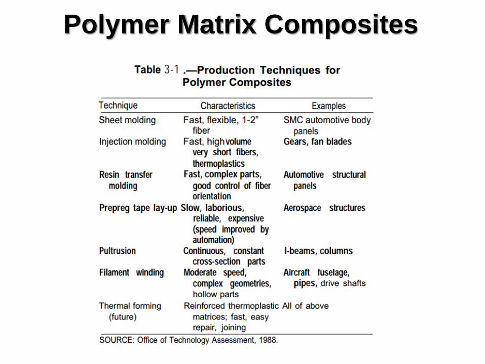
MME 3013 COMPOSITE MATERIALS Polymer Matrix Composites Manufacturing Processes
Transcript of MME 3013 COMPOSITE MATERIALS - Muğla Sıtkı...

MME 3013
COMPOSITE
MATERIALS
Polymer Matrix Composites Manufacturing Processes

Polymer Matrix Composites
The method of manufacturing composites is very
important to the design and outcome of the product
With traditional materials one starts out with a blank
piece of material ie: rod, ingot, sheet, etc and works it to
produce the desired part.
However, this is not the case with polymer-matrix
composites.
With these composites the material and the component
are being produced at the same time, therefore we aim for
the product to be a net or near net shape with little to no
post processing.

Polymer Matrix Composites
Unique to the composites industry is the ability to create
a product from many different manufacturing processes.
There are a wide variety of processes available to the
composites manufacturer to produce cost efficient
products.
Each of the fabrication processes has characteristics that
define the type of products to be produced. This is
advantageous because this expertise allows the
manufacturer to provide the best solution for the customer.

Polymer Matrix Composites
Thermosetting resins include polyesters, vinylesters, epoxies,
bismaleimides, and polyamides.
Thermosetting polyesters are commonly used in fiber-reinforced plastics,
and epoxies make up most of the current market for advanced
composites resins.
Initially, the viscosity of these resins is low; however, thermoset resins
undergo chemical reactions that crosslink the polymer chains and thus
connect the entire matrix together in a three-dimensional network. This
process is called curing.
Thermosets, because of their three-dimensional crosslinked structure,
tend to have high dimensional stability, high-temperature resistance, and
good resistance to solvents. Recently, considerable progress has been
made in improving the toughness and maximum operating temperatures
of thermosets.

Polymer Matrix Composites
Thermoplastic resins, sometimes called engineering plastics, include some
polyesters, polyetherimide, polyamide imide, polyphenylene sulfide, polyether-
etherketone (PEEK), and liquid crystal polymers. They consist of long, discrete
molecules that melt to a viscous liquid at the processing temperature, typically
500” to 700” F (260° to 3710 C), and, after forming, are cooled to an amorphous,
semicrystalline, or crystalline solid.
The degree of crystallinity has a strong effect on the final matrix properties. Unlike
the curing process of thermosetting resins, the processing of thermoplastics is
reversible, and, by simply reheating to the process temperature, the resin can be
formed into another shape if desired.
Thermoplastics, although generally inferior to thermosets in high-temperature
strength and chemical stability, are more resistant to cracking and impact
damage.
However, it should be noted that recently developed high-performance
thermoplastics, such as PEEK, which have a semicrystalline microstructure,
exhibit excellent high temperature strength and solvent resistance.

Polymer Matrix Composites
Thermoplastic resins
Thermoplastics offer great promise for the future from a manufacturing
point of view, because it is easier and faster to heat and cool a
material than it is to cure it. This makes thermoplastic matrices
attractive to high-volume industries such as the automotive industry.
Currently, thermoplastics are used primarily with discontinuous fiber
reinforcements such as chopped glass or carbon/graphite. However,
there is great potential for high-performance thermoplastics reinforced
with continuous fibers. For example, thermoplastics could be used in
place of epoxies in the composite structure of the next generation of
fighter aircraft.

Polymer Matrix Composites

Polymer Matrix Composites

Polymer Matrix Composites
PMC Processing using
Thermoset resins
Open face molding
Hand lay-up
Spray-up Automated
lay-up
Tape lay-up
Filament winding
Braiding
Tube rolling
Matched die molding
Fiber preform
Resin transfer molding
Structural reaction injection molding
Prepreg
Sheet molding compound
Bulk molding compound
Pultrusion
Impregnation
Prepreg Curing
Vacuum bag
Autoclave

Polymer Matrix Composites
PMC Processing
using Thermoplastic resins
Open face molding
Hand lay-up
Spray-up Automated lay-up
Tape lay-up
Filament winding using prepregs
Matched die molding
Fiber preform
injection molding
Prepreg
Preheating the prepreg
Pultrusion Extrusion
Only
Prepreg
Polymer Matrix Composites

Polymer Matrix Composites
Hand Lay-Up
Hand lay-up molding is the method of laying down fabrics made of reinforcement
and painting with the matrix resin layer by layer until the desired thickness is
obtained. This is the most time and labor consuming, composite processing method
but majority of aerospace composite products are made by this method in
combination with the autoclave method. Due to the hand assembly involved in the
lay-up procedure, one can align long fibers with controlled orientational quality.
Another advantage of this method is the ability to accommodate irregular-shaped
products. Such advantages are utilized in low performance composites including
fiber-glass boat and bath tub manufacturing.
Hand lay-up is the oldest and simplest method used for producing reinforced plastic
laminates. Capital investment for the hand lay-up processes is relatively low. The
most expensive piece of equipment typically is a spray gun for resin and gel coat
application. Some fabricators pour or brush the resin into the molds so that a spray
gun is not required for this step. There is virtually no limit to the size of the part that
can be made. The molds can be made of wood, sheet metal, plaster, and FRP
composites.

Polymer Matrix Composites
Hand Lay-Up
Oldest and most commonly used manufacturing method
Usually used to produce polyester or epoxy resin parts
such as boat hulls, tanks and vessels, pick-up truck
canopies
The method is quite simple, the resin and reinforcement
is placed against the surface of an open (one sided) mold
and allowed to cure or in the case of spray-up the
resin/reinforcement is sprayed onto the mold with a spray
gun
Often a gel coat is applied to the mold prior to produce
a better surface quality and protect the composite from
the elements
A gel coat is a resin usually 0.4 to 0.7 mm thick,
commonly seen on the outer surface of smaller boats

Polymer Matrix Composites
Hand Lay-Up
The pros of this process include: low initial start up cost, easy to change
mold/design, on-site production possible (ie portable process)
The cons include: labor intensive, the quality of parts depends on
operator’s skill and therefore inconsistent, only one good side to the part

Polymer Matrix Composites
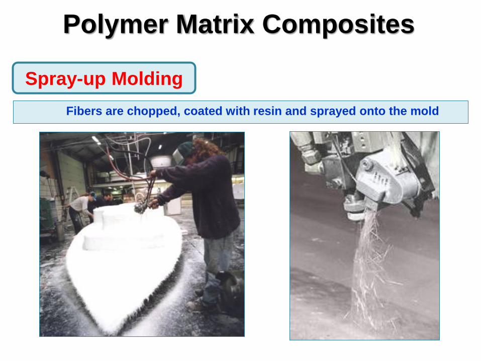
Spray-up molding is much less labor intensive than the hand lay-
up method by utilizing a spray gun and a fiber cutter.
However, only short fiber reinforced composites can be made. A
continuous fiber is fed into the cutter and chopped.
The chopped fiber is sprayed upon a mold with the stream of resin
mist and catalyst delivered through separate nozzles.
The sprayed mixture of fiber and resin soon cures on the mold at
room temperature and the product is produced.
Because of the spraying operation, large and complex-shaped
objects can be easily made.
Spray-up Molding
Polymer Matrix Composites
Fibers are chopped, coated with resin and sprayed onto the mold
Spray-up Molding

Polymer Matrix Composites
Spray-up Molding
Advantages:
Continuous process
Any materials can be used as mold.
Error can be corrected by re-spraying.
Disadvantages:
Slow.
inconsistency.
No control of fiber orientation.
Only one side finished.
Environmental unfriendly.

Polymer Matrix Composites
Prepreg can be used in a few different ways
It can be placed against a mold similar to the hand lay-up method
Once placed in the mold the material must be compressed and cured according to
a specific pressure/temperature cycle
This is often done by means of a vacuum bag where a thin plastic cover is secured
overtop of the composite and the air is vacuumed out
This process can reduce manufacturing time and produce a stronger part (if a
knitted preform is used)
Another process used is ‘automated tape lay-up’
This process uses a large automated roller similar to a packing tape roller
The roller applies the tape with pressure which eliminates the need for a vacuum
bag
Automated tape lay-up is used to produce large parts, generally in aerospace
applications and is also capable of 3-d parts
Prepreg

Polymer Matrix Composites
A pregreg (short for preimpregnated) is a composite that
comes with the resin already added to the reinforcement
This means that the only concern when working with
prepreg is shaping the part
Since the resin is already mixed (resin and catalyst) there
is a limited shelf life
For the same reason prepreg must be cured in an oven or
autoclave
Prepreg

Polymer Matrix Composites
۰Prepreg is the
composite industry’s term
for continuous fiber
reinforcement pre-
impregnated with a
polymer resin that is only
partially cured.
۰Prepreg is delivered in
tape form to the
manufacturer who then
molds and fully cures
the product without
having to add any resin.
۰This is the composite
form most widely used for
structural applications
Prepreg

Polymer Matrix Composites
Manufacturing begins
by collimating a series of
spool-wound continuous
fiber tows.
Tows are then
sandwiched and pressed
between sheets of
release and carrier
paper using heated
rollers (calendering).
The release paper
sheet has been coated
with a thin film of heated
resin solution to assure
thorough impregnation of
the fibers.
Prepreg

Polymer Matrix Composites
The final prepreg product is a thin tape consisting of
continuous and aligned fibers embedded in a partially
cured resin
Prepared for packaging by winding onto a cardboard
core.
Typical tape thicknesses range between 0.08 and 0.25
mm
Tape widths range between 25 and 1525 mm.
Resin content lies between about 35 and 45 vol%
Prepreg
Polymer Matrix Composites
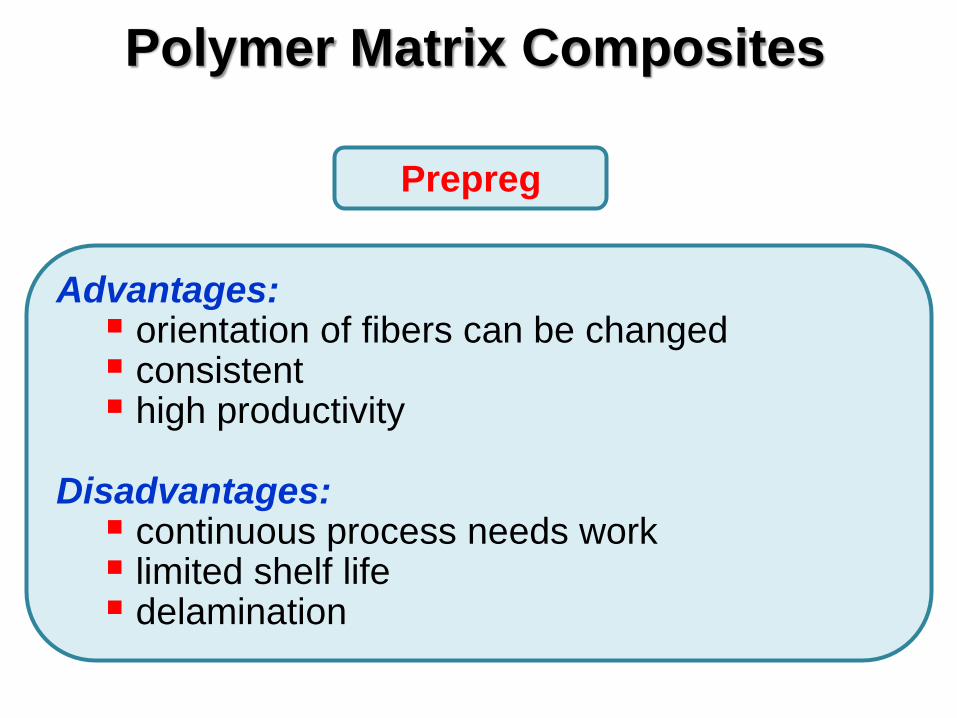
Advantages: orientation of fibers can be changed consistent high productivity
Disadvantages: continuous process needs work limited shelf life delamination
Prepreg

Processing of PMCs
Similar to
extrusion of metal
parts
Pultrusion involves
pulling resin-
impregnated glass
strands through a die
Standard extruded
shapes can easily be
produced such as
pipes, channels, I-
beams, etc.
Pultrusion

Processing of PMCs
Pultrusion
Producing composite shapes by pultrusion.

Processing of PMCs
Pultrusion

Processing of PMCs
Pultrusion
Advantages:
Automated processes.
High speed.
Versatile cross-sectional shape.
Continuous reinforcement.
Disadvantages:
Die can be easily messed up.
Expensive die.
Mainly thermoset matrix.

Processing of PMCs
A continuous reinforcement, either previously impregnated or
impregnated during winding is wound around a rotating mandrel to form
a composite part
Pros: fast lay-up speed, very accurate and repeatable product,
possibility to use continuous fiber, parts can have huge size
Cons: expensive equipment, high cost for mandrel, poor surface
finish, shape of the products limited (only cylindrical possible), curing by
heat is not easy to apply, spinning speed is limited due to resin
penetration and splashing, traveler speed and yarn breakage.
Examples: oxygen bottles for firemen, rocket motors, tennis rackets,
shafts
Filament Winding
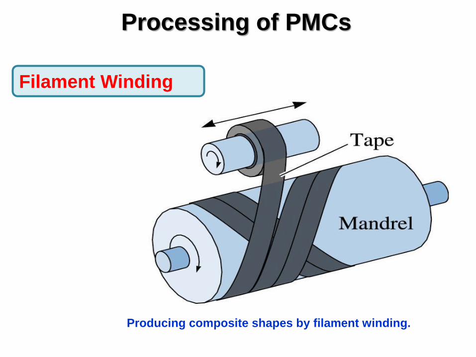
Processing of PMCs
Producing composite shapes by filament winding.
Filament Winding

Processing of PMCs
– Ex: pressure tanks
– Continuous filaments wound onto mandrel
from N. L. Hancox, (Editor), Fibre Composite Hybrid Materials, The Macmillan Company, New York, 1981.
Filament Winding

Processing of PMCs
Filament Winding
Impregnated fibers are rolled up on a
rotary mandrel, then cured in an oven

Processing of PMCs
Filament Winding
• Filament winding and fiber placement
– Fiber placement has greater
accuracy
– Fiber placement can wind on less
symmetrical and even partially
concave mandrels
• Tubes, tanks, wind turbine blades
and rockets

Processing of PMCs
Filament Winding Winding process is defined with basic parameters for
winding, like angle type, number of cycles, cycle
length, layers length, number of tows, etc.
Winding with carbon fiber Winding with glass fiber

Processing of PMCs
Resin transfer molding is a manufacturing
method that is quite similar to injection molding
where plastic is injected into a closed mold.
In the RTM process the preform (precut piece(s)
of reinforcement) is placed in the mold, the mold is
closed and the thermoset plastic matrix is injected
into the mold, once the matrix is cured the part is
ejected.
Resin Transfer Molding

Processing of PMCs
Resin Transfer Molding

Processing of PMCs
Vacuum Assisted Resin Transfer Molding
http://www.futuremediacreations.com/technoire/vartm.htm

Processing of PMCs
Resin Transfer Molding (RTM)
Pros
1. As a closed mold process, emissions are lower than open mold processes such as spray up or hand lay up.
2. The mold surface can produce a high quality finish (like those on an automobile).
3. This process can produce parts faster as much as 5-20 times faster than open molding techniques.
4. Resin transfer molding produces tighter dimensional tolerances to within 0.005 inch.
5. Complex mold shapes can be achieved. Cabling and other fittings can be incorporated into the mold designs.
Cons
1. High production volumes required to offset high tooling costs compared
to the open molding techniques.
2. Reinforcement materials are limited due to the flow and resin saturation
of the fibers.
3. Size of the part is limited by the mold.

Processing of PMCs
Researcher from Aerospace Manufacturing Technology Center
in Montreal molding members for a helicopter
Resin Transfer Molding

Processing of PMCs
Vacuum Bagging
• Provides increased part consolidation
• Reduces matched die mold costs

Processing of PMCs
Vacuum Bagging Applications: Large, one-off cruising boats, racecar components, core-bonding in production boats

Processing of PMCs
Vacuum Bagging
Advantages:
simple design
any fiber/matrix combination
ok with cheap mold material
better quality for the cost
Disadvantages:
cannot be heated up too much
breather clothe has to be replaced frequently
low pressure (760 mm Hg the most)
slowest speed
inconsistency

Processing of PMCs
Sheet Molding

Processing of PMCs
Sheet Molding
Advantages
High productivity thus inexpensive
Consistency
Disadvantages
Low volume fraction.
Only board can be made.

Polymer Matrix Composites (PMC)
A comparison of the specific modulus and specific strength of several
composite materials with those of metals and polymers.

Polymer Matrix Composites (PMC)

Polymer Matrix Composites (PMC)
The specific strength versus
temperature for several
composites and metals.

Mechanical properties of a metal are obtained using a bar or rod that is pulled in tension The tensile strength σ, the elastic modulus in the direction of the load E, and the longitudinal strain 𝜖𝐿 are obtained from the stress-strain response
𝜎 = 𝐸𝜖𝐿 The Poisson’s ratio is obtained by measuring the contraction strain 𝜖𝑇 across the sample
𝜐 = −𝜖𝑇
𝜖𝐿
Since the sample contracts, 𝜖𝑇 is negative and 𝜐 has a positive value less than 1.0 The shear modulus, G is related to E and 𝜐 by
𝐺 =𝐸
2 ∗ (1 + 𝜐)
The shear stress 𝜏 and shear strain 𝛾 are related by G:
𝜏 = 𝐺 ∗ 𝛾
Relations between the mechanical properties and structure

In metal systems the material is generally assumed to be linear, isotropic, and elastic such that only a few tests are required to obtain basic tensile stiffness properties Only two values, the tensile modulus E, and the Poisson’s ratio ν are required because of the small degree of isotropy or symmetry of the metal microstructure Metals have an infinite number of symmetry planes In contrast a material with no symmetry planes requires 21 material properties and extensive testing in order to design a structure Most composites are developed in two dimensional form and have one plane of symmetry For example a laminate plane is a unidirectional material and is transversely isotropic The stress-strain law governing this material is complicated as there are 5 material properties (σ,τ,ε,γ,S) Stress-strain law for metals: 𝜎 = 𝐸 ∗ 𝜖 For laminate composite:
𝜎1
𝜎2
𝜎3𝜏23
𝜏31
𝜏12
=
𝐸11 𝐸12 𝐸12
𝐸22 𝐸23
𝐸22
0 0 00 0 00 0 0
𝑆𝑦𝑚.
2(𝐸22 − 𝐸23) 0 0
𝐸66 0
𝐸66
∗
𝜖1
𝜖2
𝜖3𝛾23
𝛾31
𝛾12
Where 𝐸22 = 𝐸33, 𝐸12 = 𝐸13 = −𝐸11/𝜐12 = −𝐸22/𝜐21,𝐸22 = −𝐸22/𝜐23, 1
𝐸55=
1
𝐸66+
1
𝐺12
Relations between the mechanical properties and structure

E11 is determined from a tensile test conducted in the direction of the fiber orientation The value of Poisson’s ratio, ν12 is obtained by measuring the lateral contraction strain E22 is determined by cutting a laminate to pull it in tension transverse to the fiber direction The value of Poisson’s ratio, ν21 is obtained by measuring the lateral contraction strain but its value will be much less than ν12 due to fiber constraint Measuring ν23 is hard. It is small and usually ignored because most composites are two dimensional (It is the ratio of the strain across the fibers relative to the thickness strain) The value of G12, the shear modulus is measured using simple circular tubes of the material. The tubes are twisted and the resultant shear stress and strain are determined
Relations between the mechanical properties and structure

The values of longitudinal modulus E11, principle Poisson’s ratio ν11, and principle thermal expansion coefficient α11 can be expressed in terms of the matrix/fiber properties and the volume fraction of the respective ingredients according to the rule of mixtures:
𝐸11 = 𝑉𝑓 ∗ 𝐸𝑓 +𝑉𝑚 ∗ 𝐸𝑚
ν11 = 𝑉𝑓 ∗ ν𝑓 + 𝑉𝑚 ∗ ν𝑚
α 11 = 𝑉𝑓 ∗ α𝑓 + 𝑉𝑚 ∗ α𝑚
Certain assumptions are made to relate the microstructure of the ingredients to these properties: • The composite ply is macroscopically homogeneous and linearly elastic • The fibers are linearly elastic and homogeneous • The matrix is linearly elastic and homogeneous • Both the fiber and the matrix are free of voids • The interface is completely bonded and there is no interphase between the matrix and
reinforcement • The mechanical properties of the individual constituents are the same whether they
are made before or during the composite manufacturing process
Relations between the mechanical properties and structure
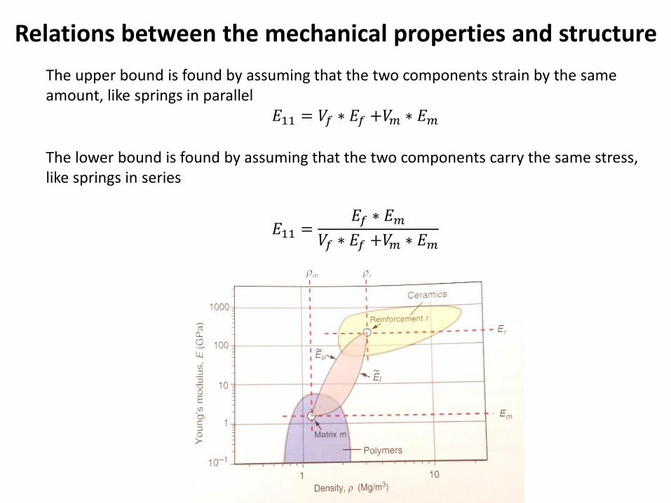
The upper bound is found by assuming that the two components strain by the same amount, like springs in parallel
𝐸11 = 𝑉𝑓 ∗ 𝐸𝑓 +𝑉𝑚 ∗ 𝐸𝑚
The lower bound is found by assuming that the two components carry the same stress, like springs in series
𝐸11 =𝐸𝑓 ∗ 𝐸𝑚
𝑉𝑓 ∗ 𝐸𝑓 +𝑉𝑚 ∗ 𝐸𝑚
Relations between the mechanical properties and structure

Cellular solids are characterized by their relative density, the fraction of the foam occupied by the solid
𝜌𝑓𝑜𝑎𝑚
𝜌𝑠=
𝑡
𝐿
2
𝐸𝑓𝑜𝑎𝑚
𝐸𝑠=
𝜌𝑓𝑜𝑎𝑚
𝜌𝑠
2
Relations between the mechanical properties and structure

In a composite material with a metal matrix and ceramic fibers,
the bulk of the energy would be transferred through the matrix.
In a composite consisting of a polymer matrix containing
metallic fibers, the energy would be transferred through the
fibers.
When the fibers are not continuous or unidirectional, the
simple rule of mixtures may not apply.
For example, in a metal fiber-polymer matrix composite,
coefficient of thermal expansion would be low and would
depend on the length of the fibers, the volume fraction of fibers
and how often the fibers touch one another.
Relations between the mechanical properties and structure

Example – You have a unidirectional, graphite/epoxy composite with the following constituent properties and 65% volume loading of fiber: Ef = 43 GPa Em = 0.5 GPa νf = 0.2 νm = 0.4 αf = 1.5*10-6/K αf = 40*10-6/K Calculate the E11, ν11, and α11 using the rule of mixtures
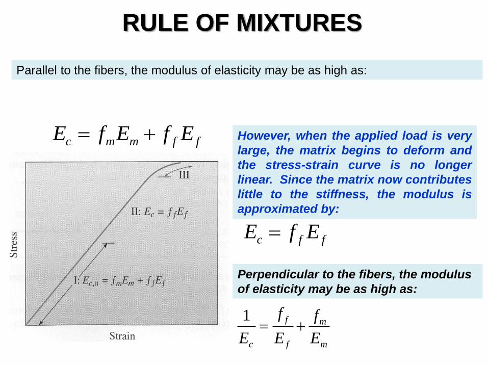
RULE OF MIXTURES
ffmmc EfEfE
ffc EfE
Parallel to the fibers, the modulus of elasticity may be as high as:
However, when the applied load is very
large, the matrix begins to deform and
the stress-strain curve is no longer
linear. Since the matrix now contributes
little to the stiffness, the modulus is
approximated by:
Perpendicular to the fibers, the modulus
of elasticity may be as high as:
m
m
f
f
c E
f
E
f
E
1

Automotive Plastics and Composites Use
SMC Sheet Molding
Compound
SMC
Sheet Molding
Compound
Plastic
Fender

SPORTS
The fibers-reinforced composites for sports.