Mm210(5b)
10
Being able to compute the angle of twist for a shaft is important when analyzing the reactions on statically indeterminate shafts. In this section we will develop a formula for determining the angle of twist (phi) of one end of a shaft with respect to its other end. The material is assumed to be homogeneous and to behave in a linear-elastic manner when the torque is applied. Considering first the case of a shaft of length L and of uniform cross section of radius c subjected to torque T at its free end, we recall from section 5.2 that the angle of twist and the maximum shearing strain are related as follows: = ∅ But in the elastic range, the yield stress is not exceeded anywhere in the shaft, Hooke’s law applies, and we have = / or recalling the torsion formula = = Equating the above equations and solving for , we write where is expressed in radians. The relation obtained shows that, within the elastic range, the angle of twist is proportional to the torque T applied to the shaft. 1 5.4 ANGLE OF TWIST
-
Upload
osmak93 -
Category
Engineering
-
view
169 -
download
0
Transcript of Mm210(5b)

Being able to compute the angle of twist for a shaft is important when analyzing the
reactions on statically indeterminate shafts.
In this section we will develop a formula for determining the angle of twist (phi)
of one end of a shaft with respect to its other end. The material is assumed to be
homogeneous and to behave in a linear-elastic manner when the torque is applied.
Considering first the case of a shaft of length L and of uniform cross section of
radius c subjected to torque T at its free end, we recall from section 5.2 that the
angle of twist and the maximum shearing strain 𝛾𝑚𝑎𝑥 are related as follows:
𝛾𝑚𝑎𝑥 =𝑐∅
𝐿
But in the elastic range, the yield stress is not exceeded anywhere in the shaft,
Hooke’s law applies, and we have 𝛾𝑚𝑎𝑥 = 𝜏𝑚𝑎𝑥/𝐺 or recalling the torsion formula
𝛾𝑚𝑎𝑥 =𝜏𝑚𝑎𝑥𝐺=𝑇𝑐
𝐽𝐺
Equating the above equations and solving for , we write
where is expressed in radians. The relation obtained shows that, within the elastic
range, the angle of twist is proportional to the torque T applied to the shaft.
1
5.4 ANGLE OF TWIST

2
In the case of a shaft with a variable circular cross section, as shown
in figure, formula for the angle of twist may be applied to a disk of
thickness dx. The angle by which one face of the disk rotates with
respect to the other is thus
𝑑∅ =𝑇𝑑𝑥
𝐽𝐺
Where J is a function of x which may be determined. Integrating in x
from 0 to L, we obtain the total angle of twist of the shaft:
=The angle of twist of one end of the shaft with respect to the other
end, measured in radians
T(x) = the internal torque at the arbitrary position x, found from the
method of sections and the equation of moment-equilibrium applied
about the shaft’s axis
J(x) = the shaft’s polar moment of inertia expressed as a function of
position x
G = the shear modulus for the material
ANGLE OF TWIST

3
ANGLE OF TWIST
If the shaft is subjected to several different torques, or the cross-
sectional area or shear modulus changes abruptly from one region
of the shaft to the next, angle of twist equation can be applied to
each segment of the shaft where these quantites are all constant. The
angle of twist of one end of the shaft with respect to the other is
then found from the vector addition of the angles of twist of each
segment. For this case
∅ = 𝑇𝐿
𝐽𝐺
Sign convention. In order to apply the above equations,
we must develop a sign convention for the internal torque
and the angle of twist of one end of the shaft with respect
to the other end. To do this we will use the right-hand
rule, whereby both the torque and angle will be positive
provided the thumb is directed outward from the shaft
when the fingers curl to give the tendency for rotation.

4
To illustrate the use of this sign convention, consider the shaft shown
in figure (a), which is subjected to four torques. The angle of twist of
end A with respect to end D is to be determined. For this problem,
three segments of the shaft must be considered, since the internal
torque changes at B and C. Using the method of sections, the internal
torques are found for each segment, figure(b). By the right-hand
rule, with positive torques directed away from the sectioned end of
the shaft, we have 𝑇𝐴𝐵 = +80N.m, 𝑇𝐵𝐶 = −70 N.m and 𝑇𝐶𝐷 =− 10 N.m. and we have
∅𝐴/𝐷 =+80𝐿𝐴𝐵𝐽𝐺+−70𝐿𝐵𝐶𝐽𝐺+−10𝐿𝐶𝐷𝐽𝐺
If the other data is substituted and the answer is found as a positive
quantity, it means that end A will rotate as indicated by the curl of
the right-hand fingers when the thumb is directed away from the
shaft. The double subscript notation is used to indicate this relative
angle of twist ∅𝐴/𝐷 ; however, if the angle of twist is to be
determined relative to a fixed point, then only a single subscript will
be used. For example if D is located at a fixed support, then the
computed angle of twist will be denoted as ∅𝐴.
ANGLE OF TWIST
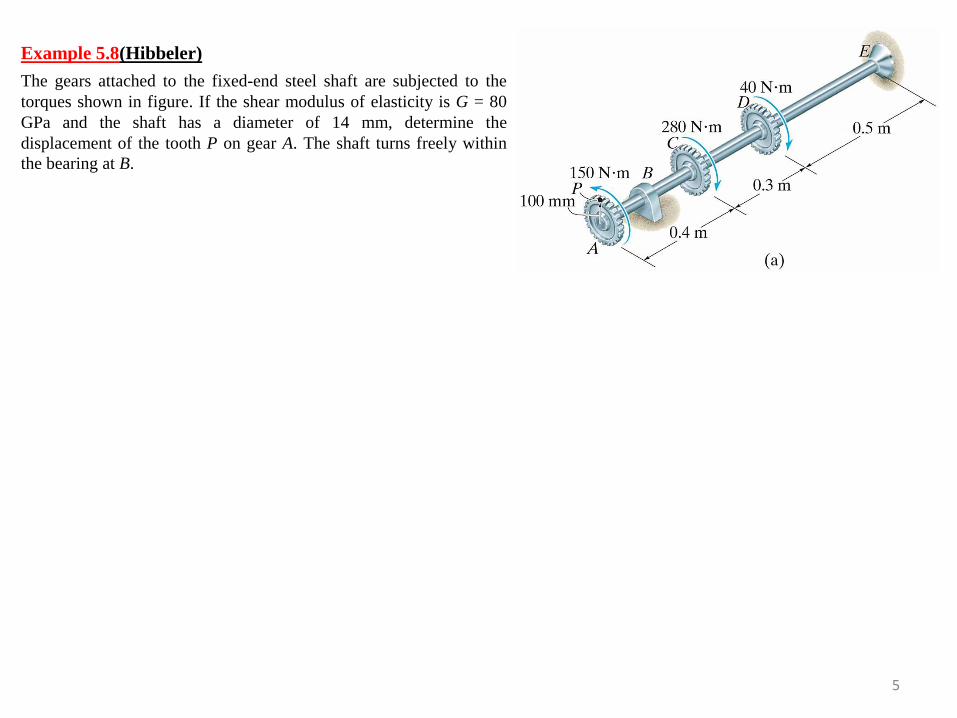
The gears attached to the fixed-end steel shaft are subjected to the
torques shown in figure. If the shear modulus of elasticity is G = 80
GPa and the shaft has a diameter of 14 mm, determine the
displacement of the tooth P on gear A. The shaft turns freely within
the bearing at B.
5
Example 5.8(Hibbeler)

The two solid steel shafts shown in figure are coupled together using the meshed
gears. Determine the angle of twist of end A of shaft AB when the torque T = 45
N.m is applied. Take G = 80 GPa. Shaft AB is free to rotate within bearings E
and F, whereas shaft DC is fixed at D. Each shaft has a diameter of 20 mm.
6
Example 5.9(Hibbeler)

7
5.5 STATICALLY INDETERMINATE TORQUE-LOADED MEMBERS
A torsionally loaded shaft may be classified as statically indeterminate if the
moment equation of equilibrium, applied about the axis of the shaft, is not
adequate to determine the unknown torques acting on the shaft. An example of
this situation is shown in figure (a). As shown on the free-body diagram, the
reactive torques at the supports A and B are unknown. We require
𝑀𝑥 = 0; 𝑇 − 𝑇𝐴 − 𝑇𝐵 = 0
Since only one equilibrium equation is relevant and there are two unknowns,
this problem is statically indeterminate.
The necessary condition of compatibility, or kinematic condition, requires the
angle of twist of one end of the shaft with respect to the other end to be equal to
zero, since the end supports are fixed. Therefore
∅𝐴/𝐵 = 0.
Realizing that the internal torque in segment AC is +𝑇𝐴, and in the segment CB
the internal torque is −𝑇𝐵, the above equation can be written as
𝑇𝐴𝐿𝐴𝐶𝐽𝐺−𝑇𝐵𝐿𝐵𝐶𝐽𝐺= 0
Solving the above two equations, reactions can be obtained.
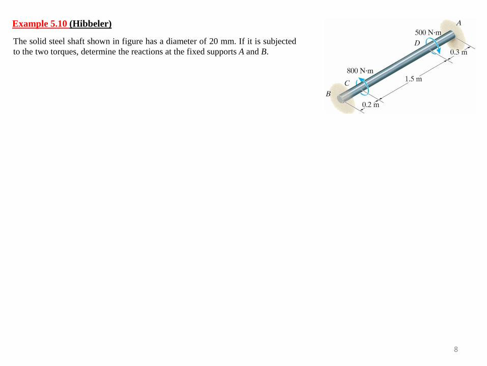
The solid steel shaft shown in figure has a diameter of 20 mm. If it is subjected
to the two torques, determine the reactions at the fixed supports A and B.
8
Example 5.10 (Hibbeler)

The shaft shown in figure is made from a steel tube, which is bonded to a brass
core. If a torque of T = 250 lb.ft is applied at its end, plot the shear stress
distribution along a radial line of its cross-sectional area. Take 𝐺𝑠𝑡 = 11.4 103
ksi, 𝐺𝑏𝑟 = 5.20 103 ksi.
9
Example 5.11(Hibbeler)

The horizontal shaft AD is attached to a fixed base at D and is subjected to the torques
shown. A 44-mm-diameter hole has been drilled into portion CD of the shaft. Knowing
that the entire shaft is made of steel for which G=77 GPa, determine the angle of twist
at end A.
10
Example 5.12 (Beer&Johnston)