MM06-FRP LADDERS EN rev3 - gratings - structures - profiles verticali/MM06... · 8.2. LADDER FIXING...
21
PAGE 1 FRP LADDERS MM06 30.07.2015 Rev. 3 FRP LADDERS COMPOSITE SOLUTION
Transcript of MM06-FRP LADDERS EN rev3 - gratings - structures - profiles verticali/MM06... · 8.2. LADDER FIXING...

PAGE 1
FRP LADDERS MM06
30.07.2015 Rev. 3 FRP LADDERS
COMPOSITE SOLUTION

PAGE 2
SUMMARY
1. USES AND CHARACTERISTICS ....................... ............................................................................................................. 3
2. REFERENCE NORMS ....................................................................................................................................................... 4
3. EMPLOYMENT FIELDS .............................. ...................................................................................................................... 5
4. MATERIALS ...................................... .................................................................................................................................. 6 4.1 PARTS OF THE VERTICAL LADDERS ......................................................................................................................... 6 4.2 VERTICAL STILES .......................................................................................................................................................... 7 4.3 RUNG PROFILES ........................................................................................................................................................... 7 4.4 SAFETY CAGE PROFILES ............................................................................................................................................ 7 4.5 FIXING CLAMPS .............................................................................................................................................................. 8 4.6 FIXING DEVICES …………………………………………………………… .................................................................... 8
5. DIMENSIONS OF THE LADDERS ...................... ............................................................................................................. 9 5.1 HEIGHT OF THE LADDERS ........................................................................................................................................... 9 5.2 MAIN DIMENSIONS OF THE LADDER AND THE SAFETY CAGE ........................................................................ 10 5.3 MAIN DIMENSIONS OF THE LADDER WITH AN INTERMEDIATE LANDING ..................................................... 11 6. TYPES OF LADDERS ............................... ..................................................................................................................... 12 6.1 STANDARD VERTICAL LADDER ............................................................................................................................... 12 6.1.1 VERTICAL LADDER TYPE 1 .................................................................................................................................... 12 6.1.2 VERTICAL LADDER TYPE 2 .................................................................................................................................... 12 6.1.3 VERTICAL LADDER TYPE 3 ..................................................................................................................................... 13 6.2 VERTICAL LADDER WITH FRONT EXIT ................................................................................................................. 14 6.2.1 VERTICAL LADDER WITH FRONT EXIT TYPE 1 ................................................................................................. 14 6.2.2 VERTICAL LADDER WITH FRONT EXIT TYPE 3 ................................................................................................. 14 6.3 VERTICAL LADDER WITH LATERAL EXIT ............................................................................................................... 15 6.3.1 VERTICAL LADDER WITH LATERAL EXIT TYPE 1 ............................................................................................. 15 6.3.2 VERTICAL LADDER WITH LATERAL EXIT TYPE 3 ............................................................................................ 15 6.3.2 REST PLATFORMS ................................................................................................................................................ 16
7. LADDER FITTINGS................................. ........................................................................................................................ 17 7.1 SAFETY FITTINGS ....................................................................................................................................................... 17 7.2 SAFETY GATE .............................................................................................................................................................. 17 7.3 SAFETY CLOSING DEVICES ...................................................................................................................................... 17 7.4 WIDENING...................................................................................................................................................................... 18 8. ASSEMBLING INSTRUCTIONS ........................ ............................................................................................................ 19 8.1 LADDER EXTENTION .................................................................................................................................................. 19 8.2. LADDER FIXING .......................................................................................................................................................... 19 8.2.1 LADDER FIXING TO CONCRETE ........................................................................................................................... 20 8.2.2. LADDER FIXING TO FRP GANGWAY .................................................................................................................... 20 8.3. SAFETY CAGE ASSEMBLING................................................................................................................................... 21

PAGE 3
1. USE AND CHARACTERISTICS
The FRP ladders are built by assembling the fiberglass and polyester resin profiles, they assure several advantages compared to the normal metal ones:
a. High resistance to chemical and atmospheric aggressions
b. High mechanical/weight ratio peso c. Long-lasting d. Lightness
e. Dimensional stability
f. High dielectric properties g. No maintenance
h. Easy to install

PAGE 4
2. REFERENCE NORMS Ladders are designed and built accordingly to the following norms:
UNI EN ISO 14122-1 Safety of machinery Permanent means of access to machinery. Part 1: choice of a fixed means of access between two levels
This norm defines the general requirements for safe access to machines, defined according to UNI EN 12100-2, and gives advice about the correct choice of access means when the necessary access to the machine is not possible directly from the ground level or from a floor. This norm applies to: − all machinery (stationary and mobile) where fixed means of access are
necessary; − means of access which are a part of a machine; − means of access to that part of the building (e.g. working platforms, walkways,
ladders) where the machine is installed, providing the main function of that part of the building is to provide a means of access to the machine;
− access means specific to the machine which are not permanently fixed to the machine and which may be removed or moved to the side for some operations of the machine (e.g. changing tools in a large press).
This norm doesn’t apply to: − lifts; − lifting platforms; − any other machine designed in order to displace people between two levels.
UNI EN ISO 14122-4 Safety of machinery Permanent means of access to machinery. Part 4: fixed ladders
This norm applies to: − all machinery (stationary and mobile) where fixed means of access are
necessary; − fixed ladders which are a part of a machine; − fixed ladders to that part of the building (e.g. working platforms, walkways,
ladders) where the machine is installed, providing the main function of that part of the building is to provide a means of access to the machine;
− ladders which are not permanently fixed to the machine and which may be removed or moved to the side or pivoted (swivel-mounted) for some operations of the machine (e.g. changing tools in a large press).
This norm doesn’t apply to: − machines which are manufactured before the date of publication of this
standard by CEN.
UNI EN 131-2
The norm determines the general project features, the requirements and the test methods for the ladders. This norm is applies to: − portable ladders. This norm doesn’t apply to: − ladders with specific use as fire department ladders or extension ladders.
Products showing this symbol are declared suitable to be used in contact with potable water by Italian and France Health Ministry.

PAGE 5
3. EMPLOYMENT FIELDS
MM’s LADDERS can be installed in any plant, but they are mainly used in corrosive environments where their characteristics are emphasized, in plants where conventional materials are not long lasting or need continuous varnishing or protection with high maintenance costs and, in any case, do not guarantee safety in the working environment.
The industries that use MM’s LADDERS are:
• Chemical Industries
• Galvanic plants
• Mineral industries
• Textile industries
• Food industries
• Electric stations
• Electric distribution cabins
• Oil plants
• Tanneries
• Water treatment plant
• Surge tanks
• Marine field
• Paper factories

PAGE 6
4. MATERIALS
4.1 PARTS OF THE LADDERS
Legend
1. Stile (see table 4.2). 2. Rung (see table 4.3). 3. Anchor bracket (see table 4.5). 4. Safety cage vertical members (see table 4.4). 5. Standard safety cage hoop (see table 4.4). 6. Safety cage hoop for front exit section (see table 4.4). 7. Safety cage hoop for lateral exit section (see table 4.4). 8. Platform step (see point 7.1). 9. Safety gate (see point 7.1). 10. Rest platform.
1
2
3 4
5
9
8
10
6
7

PAGE 7
4.2 STILE PROFILES
PROFILES CODE DESCRIPTION DIMENSIONS (mm)
BARS LENGTH (m)
WEIGHT (Kg/m) COLOR
53R58253I Stile Ladder type 02
58x25x3 6 0.80 Grey RAL 7035
53R85253I Stile Ladder type 01
85x25x3 6 1.17 Grey RAL 7035
53C90358I Stile
Ladder type 03 90x35x8 6 2.10 Grey
RAL 7035
4.3 RUNG PROFILES
PROFILES CODE DESCRIPTION DIMENSIONS (mm)
BARS LENGTH (m)
WEIGHT (Kg/m) COLOR
*
53O2821.3I Antiskid rung Ø 28x21.3 6 0.50 Grey RAL 7035
4.4 SAFETY CAGE PROFILES
PROFILES CODE DESCRIPTION DIMENSIONS (mm)
BARS LENGTH (m) WEIGHT COLOR
53P405I Flat profile 40x5 6 0.36 Kg/m
Grey RAL 7035
*
53P504I Flat profile 50x4 6
0.36 Kg/m Grey RAL 7035
*
5504CERCHIO7035
also made with flat profile
Standard hoop
Ø: 700 width: 50
thickness:10 - 0,90 Kg
Grey RAL 7035
*
5506CERCHIO7035
also made with flat profile
Front exit section hoop
Ø: 700 width: 50
thickness:10 - 1,50 Kg
Grey RAL 7035
*
5505CERCHIO7035
also made with flat profile
Lateral exit section hoop
Ø: 700 width: 50
thickness:10 - 1,00 Kg Grey
RAL 7035
*available also in

PAGE 8
4.5 ANCHOR BRACKETS
CLAMPS CODE DESCRIPTION DIMENSIONS (mm) COLOR
56ASTAFFA5 S.S. AISI 316 wall and floor anchor bracket
A: 228 B: 50 C: 70 Thk. 3
-
CSTAFFA12 FRP E23 pultruded wall anchor brackets
A: 285 B: 100 C: 60 Thk. 15
Grey RAL 7035
CSTAFFA13 FRP E23 pultruded floor anchor brackets
A: 100 B: 100 C: 60 Thk. 15
Grey RAL 7035
CSTAFFA14 FRP E23 pultruded
floor anchor brackets
A: 300 B: 100 C: 80 Thk. 15
Grey RAL 7035
CPIASTRA1 FRP counter-plate for bracket fixing on ladder type 1
A: 85 B: 70 Thk. 3
Grey RAL 7035
CPIASTRA2 FRP counter-plate for bracket fixing on ladder type 2
A: 58 B: 70 Thk. 3
Grey RAL 7035
4.6 FIXING DEVICES
PROFILES CODE DESCRIPTION DIMENSIONS (mm) COLOR
53P5825I FRP rung fixing block 70X58 Th. 25
Grey RAL 7035
5306I FRP rung fixing pin Ø 6 mm
Grey RAL 7035
S.S. BOLTS & NUTS CODE DESCRIPTION DIMENSIONS -
AISI 316 S.S. SCREWS 56 Screw used for the fixing of the S.S. bracket to the stile, for ladder types 1 and 2
M8x40 screw -
AISI 316 S.S. SCREWS 56 Screw used for the fixing of the S.S. bracket to the stile, for ladder type 3
M8x25 screw -
AISI 316 S.S. SCREWS 56 Screw used for the fixing of the FRP bracket
to the stile, for ladder types 1 and 2 M8x50 screw -
AISI 316 S.S. SCREWS 56 Screw used for the fixing of the FRP bracket to the stile, for ladder type 3 M8x35 screw -
AISI 316 S.S. SCREWS 56 Screw used for the fixing of the rings to the
vertical rod, types 1 and 2 M8x45 screw -
AISI 316 S.S. SCREWS 56 Screw used for the fixing of the rings to the vertical rod, type 3
M8x30 screw -
AISI 316 S.S. SCREWS 56 Button head screw for the fixing of the flat profiles on the rings M6x25 screw -
AISI 316 WASHERS 56 56
washers M8 M6
-
AISI 316 BOLTS 56 56 bolts M8
M6 -

PAGE 9
5. DIMENSIONS OF THE LADDERS 5.1 HEIGHT OF THE LADDERS Legend: 1. Walking surface of the arrival area 2. Walking surface of the departure area 3. Rest platform 4. Ladder flight
‘
H max = mm 10000
Ladder without rest platform (single flight)
h max = mm 6000 Ladder with staggered flights
View of the ladder with safety cage View of the ladder without safety cage

PAGE 10
5.2 MAIN DIMENSIONS OF THE LADDER AND THE SAFETY CA GE
Type of ladder Max distance between anchor brackets A Ladder type 1 mm 2000 A Ladder type 2 mm 1200 A Ladder type 3 mm 5000
Obstacle

PAGE 11
5.3 MAIN DIMENSIONS OF THE LADDER WITH A REST PLATF ORM
min 2200 max 2300
min 1680 min 1600
min 700

PAGE 12
6. TYPES OF LADDERS
6.1 STANDARD LADDER
The ladders are supplied prefabricated. FRP pins are used for the fixing of the rungs to the stiles. The safety cage is entirely made with FRP profiles, assembled with S.S. screws.
6.1.1 STANDARD LADDER TYPE 1
CSCALA1 – STANDARD LADDER TYPE 1
This type of ladder is used for the access to manhole-closed areas. To ease the access and exit it is advisable to use a safety extension (see point 7.1). Stile: rectangular profile type 85x25x3 mm Rung: diameter of profile 28x21.3 mm with antiskid surface Safety cage hoop : diameter of 700 mm Safety cage vertical members: flat profile 40x5 mm Color of the profiles and of the safety cage is grey RAL 7035 Usable width of the rung: 400 mm Total width of the ladder: 450 mm Spacing between rungs: 300 mm The total height of the safety cage*: calculated on the whole height minus 2500 mm (h = H-2500) Maximum distance between hoops: 1000 mm Maximum distance between the anchor points: 2000 mm
H ladder mm *h safety cage suggested n. of anchor brackets 2000 NN 4 3000 NN 6 4000 1500 6 5000 2500 8 6000 3500 8 7000¹ 4500 10 8000¹ 5500 10 9000¹ 6500² 12 10000¹ 7500² 12
1. For this height it is necessary to divide the ladder in two parts. Junction parts will be supplied (see point 8.1)
2. For this height it is necessary to divide in two the cage, add a hoop and supply junction devices.
6.1.2 STANDARD LADDER TYPE 2
CSCALA2 – STANDARD LADDER TYPE 2 This type of ladder is used for a maximum height of 3000 mm . Stile: rectangular profile type 58x25x3 mm Rung: diameter of profile 28x21.3 mm with antiskid surface Color of the profiles and of the safety cage is grey RAL 7035 Usable width of the rung: 400 mm total width of the ladder:450 mm Spacing between rungs: 300 mm Maximum distance between the anchor points: 1200 mm H ladder mm h safety cage suggested n. of anchor brackets
2000 NN 6 3000 NN 6

PAGE 13
6.1.3 STANDARD LADDER TYPE 3
CSCALA3 – STANDARD LADDER TYPE 3 This type of ladder is used for the access to manhole-closed areas. To ease the access and exit it is advisable to use a safety extension (see point 7.1). ACS STATEMENT – RED FILAGREE ON THE PROFILE USABLE IN CONTACT WITH POTABLE WATER Stile: “C” profile type 90x35x8 mm Rung: diameter of profile 28x21.3 mm with antiskid surface Safety cage hoop : diameter of 700 mm Safety cage vertical members: flat profile 40x5 mm or 50x4 (ACS) Color of the profiles and of the safety cage is grey RAL 7035 Usable width of the rung: 400 mm Total width of the ladder: 470 mm Spacing between rungs: 300 mm The total height of the safety cage*: calculated on the whole height minus 2500 mm (h = H-2500) Maximum distance between hoops: 1000 mm Maximum distance between the anchor points: 5000 mm H ladder mm *h safety cage suggested n. of anchor brackets
2000 NN 4 3000 NN 4 4000 1500 4 5000 2500 4 6000 3500 6 7000¹ 4500 6 8000¹ 5500 6 9000¹ 6500² 6
10000¹ 7500² 6 1. For this height it is necessary to divide the ladder in two parts. Junction parts will be supplied (see point 8.1)
2. For this height it is necessary to divide in two the cage, add a hoop and supply junction devices.

PAGE 14
6.2 LADDER WITH FRONT EXIT
6.2.1 LADDER TYPE 1 WITH FRONT EXIT
CSCALA1UF – LADDER TYPE 1 WITH FRONT EXIT This type of ladder is provided with a widening on the top that eases the exit and has no rungs on the last 1100 mm (see point 7.4). For this type of ladder we strongly recommend the supply of a safety step and a safety gate (see point 7.1 and 7.2) Stile: rectangular profile type 85x25x3 mm Rung: diameter of profile 28x21.3 mm with antiskid surface Safety cage hoop: diameter of 700 mm Front exit safety cage: diameter of 700 mm Safety cage vertical members: flat profile 40x5 mm Color of the profiles and of the safety cage is grey RAL 7035 Usable width of the rung: 400 mm Total width of the ladder: 450 mm Spacing between rungs: 300 mm Maximum distance between hoops: 1000 mm Maximum distance between the anchor points: 2000 mm DIMENSIONS OF THE EXIT: height 1100 mm from the last rung, usable width 680 mm H ladder mm h safety cage suggested n. of anchor brackets
1000+1100 NN 4 2000+1100 NN 4 3000+1100 1600 6 4000+1100 2600 6 5000+1100 3600 8 6000+11001 4600 8 7000+11001 5600 10 8000+11001 6600² 10 9000+11001 7600² 12
10000+11001 8600² 12 1. For this height it is necessary to divide the ladder in two parts. Junction parts will be supplied (see point 8.1) 2. For this height it is necessary to divide in two the cage, add a hoop and supply junction devices.
6.2.2 LADDER TYPE 3 WITH FRONT EXIT
CSCALA3 UF - LADDER TYPE 3 WITH FRONT EXIT This type of ladder is provided with a widening on the top that eases the exit and has no rungs on the last 1100 mm (see point 7.4). For this type of ladder we strongly recommend the supply of a safety step and a safety gate (see point 7.1 and 7.2) ACS STATEMENT – RED FILAGREE ON THE PROFILE USABLE IN CONTACT WITH POTABLE WATER Stile: “C” profile type 90x35x8 mm Rung: diameter of profile 28x21.3 mm with antiskid surface Safety cage hoop : diameter of 700 mm Front exit safety cage: diameter of 700 mm Safety cage vertical members: flat profile 40x5 mm or 50x4 mm (ACS) Color of the profiles and of the safety cage is grey RAL 7035 Usable width of the rung: 400 mm Total width of the ladder: 470 mm Spacing between rungs: 300 mm Maximum distance between hoops: 1000 mm Maximum distance between the anchor points: 5000 mm DIMENSIONS OF THE EXIT: height 1100 mm from the last rung, usable width 680 mm H ladder mm h safety cage suggested n. of anchor brackets
1000+1100 NN 4 2000+1100 NN 4 3000+1100 1600 4 4000+1100 2600 4 5000+1100 3600 4 6000+11001 4600 6 7000+11001 5600 6 8000+11001 6600² 6 9000+11001 7600² 6 10000+11001 8600² 6
1. For this height it is necessary to divide the ladder in two parts. Junction parts will be supplied (see point 8.1) 2. For this height it is necessary to divide in two the cage, add a hoop and supply junction devices.

PAGE 15
6.3 LADDER WITH LATERAL EXIT
6.3.1 LADDER TYPE 1 WITH LATERAL EXIT
CSCALA1U L - LADDER TYPE 1 WITH LATERAL EXIT This type of ladder is necessary in case of left or right ladder exit Stile rectangular profile type 85x25x3 Rung: diameter of profile 28x21.3 with antiskid surface Safety cage hoop: diameter of 700 mm Lateral exit safety cage hoop: diameter of 700 mm partial hoop Safety cage vertical members: flat profile 40x5 mm Color of the profiles and of the safety cage is grey RAL 7035 Usable width of the rung: 400 mm Total width of the ladder: 450 mm Spacing between rungs: 300 mm Maximum distance between hoops: 1000 mm Maximum distance between the anchor points: 2000 mm HEIGHT OF THE EXIT: 1680 mm from the last rung
H total mm h safety cage suggested n. of anchor brackets 1000+1680 NN 6 2000+1680 1180 6 3000+1680 2180 8 4000+1680 3180 8 5000+16801 4180 10 6000+16801 5180 10 7000+16801 61802 12 8000+16801 7180² 12 9000+16801 8180² 14 10000+16801 9180² 14
1. For this height it is necessary to divide the ladder in two parts. Junction parts will be supplied (see point 8.1)
2. For this height it is necessary to divide in two the cage, add a hoop and supply junction devices.
6.3.2 LADDER TYPE 3 WITH LATERAL EXIT
CSCALA3 UL - LADDER TYPE 3 WITH LATERAL EXIT This type of ladder is necessary in case of left or right ladder exit ACS STATEMENT – RED FILAGREE ON THE PROFILE USABLE IN CONTACT WITH POTABLE WATER Stile: “C” profile type 90x35x8 mm Rung: diameter of profile 28x21.3 mm with antiskid surface Safety cage hoop : diameter of 700 mm Lateral exit safety cage hoop: diameter of 700 mm partial hoop Safety cage vertical members: flat profile 40x5 mm or 50x4 mm (ACS) Color of the profiles and of the safety cage is grey RAL 7035 Usable width of the rung: 400 mm Total width of the ladder: 470 mm Spacing between rungs: 300 mm Maximum distance between hoops: 1000 mm Maximum distance between the anchor points: 5000 mm HEIGHT OF THE EXIT: 1680 mm from the last rung
H total mm h safety cage suggested n. of anchor brackets 1000+1680 NN 4 2000+1680 1180 4 3000+1680 2180 4 4000+1680 3180 6 5000+16801 4180 6 6000+16801 5180 6 7000+16801 61802 6 8000+16801 7180² 6 9000+16801 8180² 8 10000+16801 9180² 8
1. For this height it is necessary to divide the ladder in two parts. Junction parts will be supplied (see point 8.1)
2. For this height it is necessary to divide in two the cage, add a hoop and supply junction devices.

PAGE 16
6.4 REST PLATFORMS
CPIATTAFORMA - REST PLATFORM This platform is necessary whenever ladder height is over 10 meters. Minimum length: 700mm Structure: FRP profile “C” 150x45x8 mm, grating type “SCH 52/30” Structural brackets: minimum nr. 2, profile type “I” 150x75x8 mm Satefy gate structure: profile type “Q” 50x50x5 mm Safety cage vertical members: flat profile 40x5 mm Color of the profiles and of the safety cage is grey RAL 7035 Maximum distance between hoops: 1000 mm HEIGHT OF THE EXIT: height 2000 mm from the last rung Maximum height of each flight: 6000 mm
H total mm N of flights n. of intermediate platforms 11000 2 1 12000 2 1 13000 3 2 14000 3 2 15000 3 2 16000 3 2 17000 3 2 18000 3 2

PAGE 17
7. ACCESSORIES TO BE COMBINED WITH THE LADDERS 7.1 SAFETY ACCESSORIES
CODE DESCRIPTION COLOR
CMANIGLIAPRFV Wall bar made with FRP profiles, maximum length 440 mm
Grey RAL7035
55STCN40
Safety step used for the connection between the last rung and the landing floor. Dimensions 470x345 mm, Thk. 4 mm
Grey RAL7035
CPROLUNGAMENTO S.S. Safety extension pole -
7.2 SAFETY GATE
CODE DESCRIPTION COLOR
CPORTELLO
Safety gate in FRP with spring hinge. Maximum width 800 mm (the two stanchions for the fixing of the gate are not included)
Grey RAL7035
7.3 SAFETY CLOSING DEVICE
CODE DESCRIPTION COLOR
CCHIUSURASCALA1
Vertical safety closing device for FRP ladders. Dimensions of the board mm 2000x450 mm.
Grey RAL7035
CCHIUSURASCALA2 Horizontal safety closing device for FRP ladders. Grey RAL7035
PAGE 18
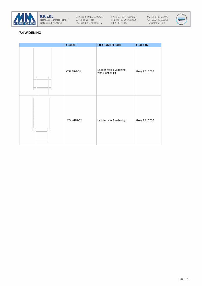
7.4 WIDENING
CODE DESCRIPTION COLOR
CSLARGO1 Ladder type 1 widening with junction kit Grey RAL7035
CSLARGO2 Ladder type 3 widening Grey RAL7035

PAGE 19
8. ASSEMBLING INSTRUCTIONS
8.1 LADDER EXTENSION
For ladders that are over 6 m long you must use stiles junctions made with specific solid FRP profiles which are fixed to the stiles with pins (fig. 1).
TYPE 1 LADDER JUNCTIONS TYPE 3 LADDER JUNCTIONS FRP flat profile dimensions 200x78 mm thk. 18 mm
hand laminated FRP flat 230x72 mm thk. 15 mm
Pultruded E23 class
Fig. 1 Juctions between ladders
8.2. LADDER FIXING
The FRP ladders are fastened with S.S. or FRP anchor brackets. The following table shows the maximum anchor point spacing accordingly to the type of ladder.
Type of ladder Max distance between clamps Ladder type 1 mm 2000 Ladder type 2 mm 1200 Ladder type 3 mm 5000
Fig. 2 Ladder with two wall anchor brackets Fig. 3 Ladder with more anchor points

PAGE 20
8.2.1 FIXING TO CONCRETE
For the fixing of a ladder to concrete, you must use S.S. or FRP anchor brackets (see table 4.5). Fixing is made by using S.S. screws with minimum diameter M8 mm length 60 mm anchoring dowels (Fig. 4).
Fig. 4 Fixing to concrete
8.2.2 FIXING TO FRP WALKWAY
For the fixing of a ladder to an FRP walkway you must use S.S. or FRP anchor brackets (see table 4.5). Fixing is made by using S.S. AISI 316 screws and self-blocking nuts (Fig. 5).
Fig. 5 Fixing to FRP walkway

PAGE 21
8.3. ASSEMBLING THE SAFETY CAGE
The safety cage has to be used for ladders which reach an arrival level higher than 3m from the departing floor. The safety cage is supplied pre-assembled and complete with all the devices to allow a fast and easy assembling (Fig. 6). The drilled holes must be of the same diameter of the screws, this avoids backlash.
Fig. 6 : safety cage assembling