MLK-protec cast iron drainage pipe system - Düker GmbH · MLK-protec cast iron drainage pipe...
40
Transcript of MLK-protec cast iron drainage pipe system - Düker GmbH · MLK-protec cast iron drainage pipe...


22
MLK-protec cast iron drainage pipe system

3
TABLE OF CONTENTSMLK-protec cast iron drainage pipe system
04 Installation instructions
pageInstallation instructions pro-cut tape 26 - 27
05 Laying instructions
Grease drain lines 28 - 29Underground installation 31 - 33
Fixings, fire and noise protection For specifications and recommendations on these and other topics, please refer to the latest version or the SML Specifier‘s Manual.
06 Specifying texts
Specifying texts 34 - 37
General information
pageMLK-protec coatings 4Application, planning and installation 5Approvals 5
01 Resistance chart
Resistance chart 6-7
02 MLK-protec range of products
MLK-protec pipes 9Düker pro-cut tape 9MLK-protec reducers 10MLK-protec down pipe supports 10MLK-protec bends 11 - 13MLK-protec S-bends 13MLK-protec branches 14 - 15MLK-protec inspection pipes 16MLK-protec plugs 17MLK-protec siphons 17MLK-protec pipes/adapters with wall flange 18MLK-protec connecting bends 18MLK-protec connection pieces 19
03 Couplings programme
Dükorapid® coupling 20Dükorapid® Inox coupling 20Rapid Inox coupling 22Connect-G Inox coupling 21Connect-F Inox coupling 22 Kombi grip collar 22Grip Collar 23 Fire protection coupling BSV 90 23Düker EK Fix coupling 24Konfix Multi coupling 24Multiquick coupling 25Transition coupling 25

fully cross-linked epoxy, double layer thickness
of at least 240 µm
grey cast iron with flake graphite
as per EN 877
thermal zinc spray coating min. 130 g/m²
zinc-compatible cover coat, grey (RAL 7024 graphite grey)
epoxy powder coating grey
grey cast iron with flake graphite as per DIN EN 877
4
MLK-protec cast iron drainage pipe system
The manufacture of cast iron drainage pipes, fittings and corre-sponding couplings is based primarily on the European standard EN 877. MLK-protec was developed particularly for the drain-age of waste waters of a certain aggressiveness in domestic areas. It bears a special coating inside as well as an outside coating that is suitable for underground installation. The advan-tages known from the standard version SML - stability, installa-tion friendliness, noise and fire protection - remain unchanged.
Material
The material of MLK-protec pipes and fittings is identical to that of the standard SML pipes:
• grey cast iron with flake graphite type at least EN-GJL-150 as per EN 1561
Pipe Coating
The inside surfaces are machined extensively before coating in order to avoid undercuts and air inclusions caused by them.The pipe edges are chamfered twice. The inside coating of MLK-protec pipes is composed as follows:
• a double layer of two-component wet epoxy, total thickness at least 240 µm.
• separate coating of the pipe edge.
The epoxy material is a new development with optimised adher-ence and cross-linking, very good flow characteristics and excel-lent chemical resistance.
The outside coating of MLK-protec pipes follows EN 877 for underground installation:
• thermal spray zinc coating of min. 130 g/m²• compatible cover coat, grey colour
Coating of Fittings
The metallic surfaces of the fittings are cleaned by abrasive blasting, then heated to approx. 200 °C and coated with epoxy powder by fluidised bed sintering. On larger fittings and on those with complicated geometries, the poxy powder is sprayed on by hand and then burnt in.
• inside and outside epoxy powder coating in grey colour, layer thickness at least 240 µm.
MLK-protec
APPLICATION, CHARACTERISTICS
Alternative Version: MLK-indoor Pipes for Installation Inside Buildings
If the MLK pipes are laid exclusively within a building with-out any particular corrosive attack on their outside surfaces, it is possible to use MLK-indoor pipes. Their outside coating con-sists only of the grey cover coat, without zinc coating. The inside coating is identical with MLK-protec. These MLK-indoor pipes should be combined with normal MLK-protec fittings and with couplings that are suitable for the intended application.
chamfers
pipe edge

5
APPLICATION, CHARACTERISTICSAPPLICATION, CHARACTERISTICS
Laying and Handling
MLK-protec pipes can be cut to length with tools available in the trade, particularly with special pipe saws, belt saws, or a disc cutter with guidance. The saw discs or belts must be suita-ble for cast iron. The cut edges of MLK-protec and MLK-indoor pipes must be protected on site. It is essential to use the Düker pro-cut tape for this cut edge protection. For further information please refer to pages 28/29.
Packing
MLK-protec pipe bundles are protected from damage caused by the forklift fork by an additional film. MLK-protec fittings are packed individually in blister foil sacks.
Reaction to Fire - Non-combustibility
The Düker MLK-protec drainage pipe system corresponds to the reaction to fire A2, s1, d0 „non-combustible“ as per EN 13501-1.
Areas of application
MLK-protec is suitable for drainage pipes charged with waste water whose aggressiveness surpasses the normal domestic use, e.g. in professional kitchens and canteens.
For the following applications, we recommend to consult us:
• food and beverage industries• meat processing and butcheries• thermal and medical spas• hospitals and care facilities• school, hospital or photo laboratories
Planning and installation
Planning and installation of MLK-protec pipelines follow the technical regulations and stipulations of
• EN 12056 Gravity drainage systems inside buildings • EN 752 Drain and sewer systems outside buildings • EN 1610 Construction and testing of drains and sewers • EN 1825-2 Grease separators. Selection of nominal size,
installation, operation and maintenance
and other applicable European, national or local standards and regulations.
CE Marking
The latest version of the relevant product standard EN 877 contains an annex ZA regard-ing CE marking. Since 2009, the CE marking has
been obligatory on cast iron pipe products corresponding to this standard.
Since July 2013, the European Construction Products Regulation CPR is to be observed for these products. Since this date, the CE marking is based on a Declaration of Performance DOP. You will find the latest version of the Düker Declarations of Perfor-mance on www.dueker.de/dop.
GEG quality association cast iron drainage technology
In order to fulfil the increasing safety require-ments of our partners in plumbing, trade, plan-ning and authorities, the European cast iron pipe industry as well as suppliers of accessories founded the IZEG. IZEG and the integrated qual-ity association GEG award a RAL quality label to
cast iron drainage pipes and fittings that have passed a number of tests defined in the RAL GEG quality directives.
Those awarded with the RAL GEG quality label are subject to an initial test as well as regular third-party surveillance by an authorized institute. The requirements for this label are consid-erably higher than those of EN 877, particularly regarding the resistance of the inside coating. Unlike the CE marking, this qual-ity label guarantees users a permanently high product quality.
The latest edition 2014 of the RAL-GZ 689 quality and test reg-ulations contains a separate chapter on drainage pipes and fit-tings for the drainage of aggressive waste water. Further to the requirements on the resistance of the inside coating, which already apply to standard SML, there is a requirement for a test on the freedom from pores of the inside coating – a high voltage test with test electrodes made of conductive rubber or brushes.
Düker obtained the corresponding quality seal for their MLK-protec drainage pipe system in 2016.

6
The following resistance chart should give the specifier some information on the material to select. The chart is not complete and is valid for non-pressure pipe systems with discontinuous operation at the specified temperature.
It shows the resistance of the inside coating of MLK-protec pipes and fittings and of the EPDM and NBR rubber sealings.
As the level of chemical resistance also depends on the combi-nation of various factors such as temperature, pressure, concen-tration, contamination and a possible mixing of agents, as well as duration, intensity and surface of contact, this chart should be used as a guideline only.
If you are in doubt, please contact our technical staff, also for chemicals not mentioned. Please use the inquiry form chemical resistance, which you will find on our website at:www.dueker.de > Drainage Technology > Downloads.
01 Resistance chart
description formula conc. pHMLK-protec EPDM NBR
20 °C 50 °C 90 °C 20 °C 50 °C 90 °C 20 °C 50 °C 90 °C
Watersweet water + + + + + + + + +
salt water H2O/NaCl 30g/l 5.6 + + + + + + + + +
demineralised water H2O 100% 6.4 + + – + + – + + –
waste water as per EN 877 7.0 + + + + + + + + +
Inorganic acidssulphuric acid H2SO4 10% 1.0 + + – + + – – – –
nitric acid HNO3 10% 2.0 + – – + – – – – –
phosphoric acid H3PO4 25% 1.0 + – – + – – – – –
phosphoric acid H3PO4 10% 1.3 + – – + – – – – –
phosphoric acid H3PO4 5% 1.8 + + – + + – – – –
phosphoric acid H3PO4 3% 2.0 + + + + + + – – –
hydrochloric acid HCL 10% 0.7 – – – – – – – – –
hydrochloric acid HCL 5% 1.0 + – – + – – – – –
hydrogen peroxide H2O2 10% 3.5 + – – + – – – – –
Organic acidsacetic acid 10% 2.0 + – – + – – – – –
acetic acid 30% 1.7 + – – + – – – – –
lactic acid 1% 2.0 + – – + – – – – –
lactic acid 10% 1.1 + – – + – – – – –
citric acid 5% 1.5 + + + + + + – – –

7
RESISTANCE CHART
description formula conc. pHMLK-protec EPDM NBR
20 °C 50 °C 90 °C 20 °C 50 °C 90 °C 20 °C 50 °C 90 °C
Basessodium base Na2CO3 10% 11.4 + + – + + – + + –
sodium base Na2CO3 50% 11.9 + + – + + – + + –
potassium base K2CO3 10% 12.0 + + – + + – + + –
potassium base K2CO3 50% 12.4 + + – + + – + + –
ammonium NH3 10% 12.1 + + + + + + – – –
Javel water NaCIO 10% 12.0 + + + + + + – – –
Javel water NaCIO 30% 12.0 + + + + – – – – –
Saltsmonosodium phosphate NaH2PO4 3% 4.2 + + –
ammonium sulphate (NH4)2SO4 3% 6.7 + + –
potassium chloride KCl 3% 4.2 + + –
Solventsturpentine + – +
super petrol + – +
diesel + – +
crude oil + – +
xylene C8H10 + – –
cyclohexane C6H12 + – +
propanone (acetone) C3H60 + + –
ethanol C2H5OH + + –
glycol (ethylene glycol) C2H6O2 + + +
Detergentsmulti-purpose cleaner 5% + + + + + +
washing-up liquid 5% + + + + + +
washing agent 5% + + + + + +
bathroom cleaner 5% + + + + + +
vinegar-based cleaner 5% + + + + + + – – –
chlorine-free toilet cleaner 10% + +
toilet cleaner with chlorine 10% + +
drain cleaner with chlorine 10% + +
disinfectant 5% + +
stain remover 5% + +

8
02 MLK-protec Range of products

coupling t
fitting
DE
e pipeL
ØD
x8
L
L
A
D1
D2
13*
cBA
9
MLK-protec pipe DIN 19522 L = 3,000 mm
DN kg item no.
50 15.8 239289
70* 20.0 660097
80 20.2 239291
100 25.6 660187
125 35.0 660277
150 42.8 660367
200 71.5 660457
250 91.0 660657
300 125.2 660667
400 175.5 660607* obsolete model, on request
Düker pro-cut tape as cut edge protectionitem no.
Spool with 10 m each 239071
Spool with 20 m each 239100
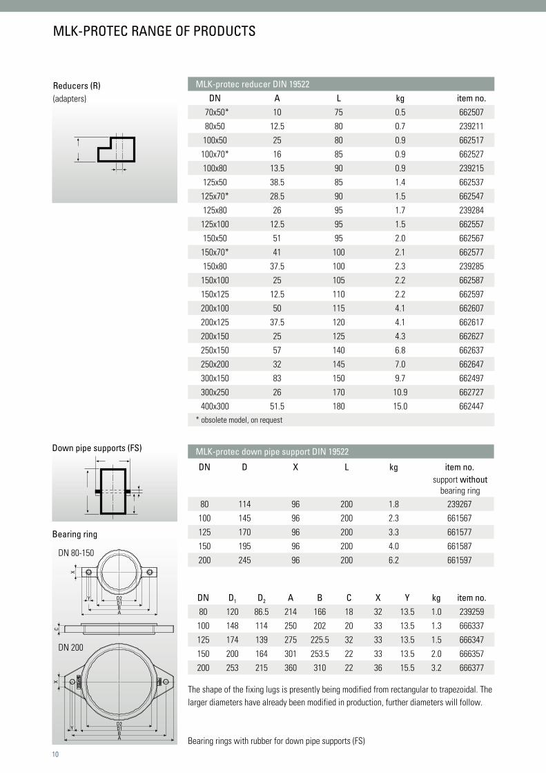
MLK-PROTEC RANGE OF PRODUCTS
Constructional dimensions:
pipe diameterwall thickness insertion lenghts (sealing zone)pipe weightssurface
MLK-protec pipes
Düker pro-cut tape
Important: pipe ends cut on site have to be protected with the Düker pro-cut tape.
Butyl rubber tape. 10 m are sufficient for approx. 30 cut edges DN 100. Düker pro-cut tape has to be expressly ordered, it is not delivered automatically with the pipes.
All dimensions in mm
MLK-protec pipes and fittings (EN 877 and DIN 19522)nominaldiameter
exteriordiameter
wall thickness pipes and fittings
insertion length (sealing zone)
admissible interior pressure
pipe weight empty
surface ca. m²
DN DE tolerance nominal minimum t pipes up to fittings*** up to ca. kg/m per m
50 58 +2/-1 3.5 3.0 30 10 bar 10 bar 5.3 0.18
70* 83 +2/-1 3.5 3.0 35 10 bar 10 bar 6.7 0.26
80** 83 +2/-1 3.5 3.0 35 10 bar 10 bar 6.7 0.26
100 110 +2/-1 3.5 3.0 40 10 bar 10 bar 8.5 0.35
125 135 +2/-2 4.0 3.5 45 10 bar 10 bar 11.7 0.42
150 160 +2/-2 4.0 3.5 50 10 bar 5 bar 14.3 0.50
200 210 +2.5/-2.5 5.0 4.0 60 10 bar 5 bar 23.8 0.65
250 274 +2.5/-2.5 5.5 4.5 70 10 bar 3 bar 30.3 0.85
300 326 +2.5/-2.5 6.0 5.0 80 10 bar 3 bar 41.7 1.02
400 429 +2/-3 6.3 5.0 80 10 bar 2 bar 58.5 1.35 * obsolete model, on request
** the nominal diameter DN 80 with a minimum interior diameter of 75 mmcorresponds to DN 80 as per EN 12056-2 as well as to DN 75 as per EN 877 (product standard)*** except inspection pipes, siphons, hermetic plugs and connection pieces
10
MLK-protec reducer DIN 19522DN A L kg item no.
70x50* 10 75 0.5 662507
80x50 12.5 80 0.7 239211
100x50 25 80 0.9 662517
100x70* 16 85 0.9 662527
100x80 13.5 90 0.9 239215
125x50 38.5 85 1.4 662537
125x70* 28.5 90 1.5 662547
125x80 26 95 1.7 239284
125x100 12.5 95 1.5 662557
150x50 51 95 2.0 662567
150x70* 41 100 2.1 662577
150x80 37.5 100 2.3 239285
150x100 25 105 2.2 662587
150x125 12.5 110 2.2 662597
200x100 50 115 4.1 662607
200x125 37.5 120 4.1 662617
200x150 25 125 4.3 662627
250x150 57 140 6.8 662637
250x200 32 145 7.0 662647
300x150 83 150 9.7 662497
300x250 26 170 10.9 662727
400x300 51.5 180 15.0 662447* obsolete model, on request
MLK-protec down pipe support DIN 19522
DN D X L kg item no.support without
bearing ring80 114 96 200 1.8 239267
100 145 96 200 2.3 661567
125 170 96 200 3.3 661577
150 195 96 200 4.0 661587
200 245 96 200 6.2 661597
Reducers (R)(adapters)
Down pipe supports (FS)
Bearing ring
MLK-PROTEC RANGE OF PRODUCTS
DN 80-150
DN 200
DN D1 D2 A B C X Y kg item no.80 120 86.5 214 166 18 32 13.5 1.0 239259
100 148 114 250 202 20 33 13.5 1.3 666337
125 174 139 275 225.5 32 33 13.5 1.5 666347
150 200 164 301 253.5 22 33 13.5 2.0 666357
200 253 215 360 310 22 36 15.5 3.2 666377
The shape of the fixing lugs is presently being modified from rectangular to trapezoidal. The larger diameters have already been modified in production, further diameters will follow.
Bearing rings with rubber for down pipe supports (FS)

x
x
88°
x
x68 °
45 °
x
x
30 °
x
x
15 °
xx
x
x
88°
x
x68 °
45 °
x
x
30 °
x
x
15 °
xx
x
x
88°
x
x68 °
45 °
x
x
30 °
x
x
15 °
xx
x
x
88°
x
x68 °
45 °
x
x
30 °
x
x
15 °
xx
11
Bends 88°
Bends 68°
Bends 45°
Bends 30°
MLK-PROTEC RANGE OF PRODUCTS
MLK-protec bend DIN 19522DN X kg item no.50 75 0.7 661057
70* 90 1.1 661117
80 95 1.2 239213
100 110 2.1 661177
125 125 3.2 661237
150 145 5.2 661297
200 180 8.8 239605
250 225 13.8 239643
300 260 28.0 240276
DN X kg item no.
50 45 0.5 661017
70* 50 0.7 661077
80 60 0.9 239232
100 60 1.3 661137
125 70 2.0 661197
150 80 3.1 661257
200 95 5.2 661317
250 110 9.1 661367
300 130 14.7 661387* obsolete model, on request
DN X kg item no.50 50 0.5 661027
70* 60 0.9 661087
80 60 0.9 239201
100 70 1.5 661147
125 80 2.3 661207
150 90 3.5 661267
200 110 5.5 661327
250 130 10.3 661377
300 155 17.0 661397
400 257 36,0 661287
DN X kg item no.50 65 0.7 661037
70* 75 1.1 661097
80 80 1.2 239264
100 90 1.9 661157
125 105 2.9 661217
150 120 4.3 661277

K
X1
X288
°
K
X1
X2
45°
44 °
44 °X2
X3
X3
X1
X1
X1
X1 44 °
44 °X2
X3
X3
K
X1
X288
°
K
X1
X2
45°
44 °
44 °X2
X3
X3
X1
X1
X1
X1 44 °
44 °X2
X3
X3
K
X1
X288
°
K
X1
X2
45°
44 °
44 °X2
X3
X3
X1
X1
X1
X1 44 °
44 °X2
X3
X3
x
x
88°
x
x68 °
45 °
x
x
30 °
x
x
15 °
xx
12
Bends 88° with 250 mm spigot (LB)
Bends 45° with 250 mm spigot (LB)
Double bends 88°from 2 bends 44° (DB)
MLK-protec bend DIN 19522DN X1 X2 K* kg item no.
100** 250 110 140 4.6 662087
*dimension for maximum cut-back**obsolete model, on request
MLK-protec bend DIN 19522DN X1 X2 K* kg item no.
100** 250 70 280 4.2 662077
*dimension for maximum cut-back**obsolete model, on request
MLK-protec bend DIN 19522DN X1 X2 X3 kg item no.100 70 140 170 3.2 661507
MLK-PROTEC RANGE OF PRODUCTS
Bends 15° MLK-protec bend DIN 19522DN X kg item no.50 40 0.4 661007
70* 45 0.6 661067
80 50 0.7 239233
100 50 1.0 661127
125 60 1.7 661187
150 65 2.5 661247
200 80 4.6 661307* obsolete model, on request

K
X1
X288
°
K
X1
X2
45°
44 °
44 °X2
X3
X3
X1
X1
X1
X1 44 °
44 °X2
X3
X3
Lx
L
x
KK
r67
45 °
L
130
xx
x 15 °
x
A
L
30 °x
x
A
L
45 °xx
A
L
L
65
xx
200
Lx
x
Lx
L
x
KK
r67
45 °
L
130
xx
x 15 °
x
A
L
30 °x
x
A
L
45 °xx
A
L
L
65
xx
200
Lx
x
13
MLK-protec bend DIN 19522DN X1 X2 X3 kg item no.80 60 301 273 3.4 239343
100 70 312 291 4.8 662747
125 80 322 308 6.8 662757
150 90 334 326 9.6 662767
MLK-protec bend DIN 19522DN X K* L kg item no.100 312 100 150 5.0 662777
*dimension for maximum cut-back
MLK-protec S-bend DIN 19522DN X L kg item no.
100** 70 270 3.5 662877
**obsolete model, on request
MLK-PROTEC RANGE OF PRODUCTS
Bends 88° (BB) with 250 mm steadying distance for the transition of down pipes to horizontal pipes
Bends 135° for ventilation (bypass)
S-bends (SP)offset (A) = 130 mm

45 °
L X2
X3
X1
Abzweig 45°
L
Bogen 45 °
BA
K
KAbzweig 45°
L
Bogen 45°
B
A
14
MLK-PROTEC RANGE OF PRODUCTS
MLK-protec branch DIN 19522DN X1 X2 X3 L kg item no.
50 x 50 50 135 135 185 1.4 663007
70 x 50* 40 150 150 190 1.6 663037
80 x 50 50 140 140 190 1.7 239222
70 x 70* 55 160 160 215 2.3 663067
80 x 80 65 160 160 225 2.4 239225
100 x 50 35 165 165 200 2.5 663097
100 x 70* 50 185 185 235 3.3 663127
100 x 80 55 175 175 230 3.3 239214
100 x 100 70 205 205 275 4.2 663157
125 x 50 20 185 185 205 3.4 663187
125 x 70* 40 200 200 240 4.3 663217
125 x 80 40 200 200 240 3.6 239251
125 x 100 60 220 220 280 5.2 663247
125 x 125 80 240 240 320 6.4 663277
150 x 70* 30 215 215 245 5.6 663337
150 x 80 40 215 215 245 5.2 239254
150 x 100 55 240 240 295 6.4 663367
150 x 125 70 255 255 325 8.3 663397
150 x 150 90 265 265 355 9.2 663427
200 x 70* 15 240 240 255 8.1 663487
200 x 80 15 240 240 255 8.5 239255
200x 100 40 265 265 305 10.0 663517
200 x 125 55 280 280 335 11.9 663547
200 x 150 75 300 300 375 12.4 663577
200 x 200 115 340 340 455 17.2 663607
250 x 100 15 310 310 325 15.4 663637
250 x 125 35 335 335 370 17.7 664507
250 x 150 55 350 350 405 20.4 664517
250 x 200 90 385 385 475 25.1 663647
250 x 250 130 430 430 560 31.5 663657
300 x 100 5 345 345 350 19.0 663667
300 x 125 15 360 360 375 21.5 664527
300 x 150 35 380 380 415 23.0 664537
300 x 200 70 415 440 485 34.0 664447
300 x 250 115 465 465 580 42.1 663677
300 x 300 155 505 505 660 50.1 663687
400 x 300 105 555 565 660 60.0 663697
*obsolete model, on request
Branches 45°
MLK-protec double branch 45°DN1 DN2 DN3 X1 X2 X3 kg item no.100 100 100 260 190 190 5.1 239565
125 100 100 280 220 220 6.5 239606
150 100 100 280 225 225 8.2 661447
MLK-protec Double Branches 45°
45°
X1
X2
X3

L
K
Abzweig 88° Bogen 88°B
A
LX
2
X3
45 °
X1
88 °
Lx
L
x
KK
r67
45 °
45 °
max./min.
L X2
X3
X1
X3
88 °
LX
5X
1
LX
4X
2
DN 2 DN 3
DN 1
X1
X3
L
X2
45 °
70 °
X2
70 °
X1
X3
L
DN 1
DN 2
DN 3
LX
2
X3
X1
88 °
45 °DN 1
DN 2
DN 1
DN 2
DN 2
90 °
LX
2
X3
45 °
X1
88 °
K
DN 1
DN 2
LX
2
X3
45 °
X1
88 °
K
LX
2
K
90 °
X1
X3
X4
X3
88 °
LX
5X
1
LX
4X
2
DN 2 DN 3
DN 1
X1
X3
L
X2
45 °
70 °
X2
70 °
X1
X3
L
DN 1
DN 2
DN 3
LX
2
X3
X1
88 °
45 °DN 1
DN 2
DN 1
DN 2
DN 2
90 °
LX
2
X3
45 °
X1
88 °
K
DN 1
DN 2
LX
2
X3
45 °
X1
88 °
K
LX
2
K
90 °
X1
X3
X4
15
MLK-PROTEC RANGE OF PRODUCTS
MLK-protec branch DIN 19522DN X1 X2 X3 L kg item no.
50 x 50 79 66 80 145 0.9 663027
70 x 50* 83 72 90 155 1.4 663057
80 x 50 95 85 90 180 1.5 239256
70 x 70* 97 83 95 180 1.7 663087
80 x 80 95 85 95 180 1.8 239257
100 x 50 94 76 105 170 2.1 663117
100 x 70* 102 88 110 190 2.4 663147
100 x 80 105 85 110 190 2.5 239250
100 x 100 115 105 120 220 2.9 663177
125 x 50 98 82 120 180 3.0 663207
125 x 70* 107 93 125 200 3.4 663237
125 x 80 110 94 125 205 3.1 239252
125 x 100 125 110 130 235 4.0 663267
125 x 125 137 123 135 260 4.6 663297
150 x 50 100 100 140 200 4.4 663327
150 x 100 130 115 145 245 5.5 663387
150 x 125 147 128 150 275 6.2 663417
150 x 150 158 142 155 300 6.9 663447
*obsolete model, on request
Branches 88°access angle 45°
MLK-protec double branch DIN 19522DN1 DN2 DN3 X1 X2 X3 X4 X5 L kg item no.100 x 100 x 100 120 120 120 110 110 230 3.4 663877
MLK-protec corner branch DIN 19522DN1 DN2 DN3 X1 X2 X3 L kg item no.100 x 100 x 100 115 105 120 220 3.4 662037
Double branches 88°access angle 45°
Corner branches 88° (EA)access angle 45°;corner angle 90°

16
MLK-PROTEC RANGE OF PRODUCTS
MLK-protec inspection pipe rectangular DIN 19522 DN A B C D E L M N kg item no.100 95 160 100 200 230 340 130 132 7.6 669647
125 104 190 125 225 255 370 150 160 10.3 239271
150 117 215 150 250 280 395 170 185 13.0 239272
200 146 265 199 300 330 465 200 234 22.0 239273
250 180 330 259 350 380 570 250 300 35.7 239274
DN 100 to DN 200 with toroidal sealing ring in EPDM. DN 250 with 6 hermetic plug screws and flat sealing in EPDM.
MLK-protec Inspection Pipeswith rectangular openingfor horizontal and down pipes
MLK-protec Inspection Pipeswith round opening for down pipe
MLK-protec inspection pipe round DIN 19522DN A B D L M kg item no.50 58 90 53 190 60 1.8 239275
70* 71 105 73 210 79 2.3 239276
80 69 110 78 220 80 3.2 239277
100 82 125 104 260 96 3.8 239248*obsolete model, on request
With toroidal sealing ring in EPDM. Torque at the cover screws: 15 Nm
Note: the cover shape, cover seat on the body, sealing and bolts were modified from manufac-turing date January 2017.
When ordering replacements for cover, sealings and fixing materials please indicate the required cover version:
Cover former version (manufacture until autumn 2016) circular cover with flat outside surface with marking „Deckelsitz nach Montage prüfen“
Cover new version (manufcature from January 2017) circular cover with fixing lugs, outside surface recessed with Düker marking

DN 3
X1
X1
X2X3
DN 1
DN 2
X4 X4
90 °
L D
A
B
L EDD
L
l3l1l2
l2b
a
100
HX
2X
1
LX3 X4
w
17
DN 150-200
A
C
D E
DN 100-125
A
C
B D E
MLK-protec hermetic plug incl. sealing ringDN A B C D E kg item no.100 179 122 86 24 25 1.3 664807
125 204 145 86 24 25 1.4 664817
150 200 – 85 24 25 2.1 664827
200 248 – 71 24 25 3.3 664837
rubber seal in EPDM (spare part)DN kg item no.100 0.05 100700
125 0.07 100701
150 0.09 100702
200 0.11 100703
MLK-protec hermetic Plugs
MLK-PROTEC RANGE OF PRODUCTS
MLK-protec plug DIN 19522DN L kg item no.50 30 0.2 665507
70* 35 0.4 665517
80 35 0.5 239247
100 40 0.8 665527
125 45 1.1 665537
150 50 1.7 665547
200 60 3.1 665557
250 70 6.0 665567
300 80 9.5 665577*obsolete model, on request
Plugs (ED)
MLK-protec siphon DIN 19522DN L H X1 X2 X3 X4 W kg item no.50 190 250 182 68 122 68 60 3.0 239281
70* 265 293 200 93 172 93 60 5.0 239282
80 265 285 190 95 170 95 80 5.8 239283
100 325 392 282 110 215 110 100 9.9 239279
125 390 446 316 130 260 130 100 13.0 239280
150 470 493 348 145 325 145 100 19.5 669667*obsolete model, on request
Siphons (G)with inspection opening below
MLK-protec inspection pipe round DIN 19522DN A B D L M kg item no.50 58 90 53 190 60 1.8 239275
70* 71 105 73 210 79 2.3 239276
80 69 110 78 220 80 3.2 239277
100 82 125 104 260 96 3.8 239248*obsolete model, on request
The supplying side of the SML odour traps may be connected either to the horizontal or the ver-tical pipe. Bends can guide the outlet into different directions. The supply opening not used is to be closed with a hermetic plug with press-sealing automatically supplied.

DN 1DN 2
K1200
K2 110
DN 1
DN 2
60
70
K2
DN 1
DN 2
DN 3
K1
K2
200
160
D
D 2
DN 1DN 2
K1200
K2 110
DN 1
DN 2
60
70
K2
DN 1
DN 2
DN 3
K1
K2
200
160
D
D 2
150
A
100350
D1D2
400 20060
8
38
150
A
100350
D1D2
400 20060
8
38
150A
100
350
D1D2
400
200
60
838
150A
100
350
D1D2
400
200
60
838
V BV
18
MLK-PROTEC RANGE OF PRODUCTS
Wash basin y-joint 90° (OH)
MLK-protec wash basin connecting bend DIN 19522DN1 DN2 K1* K2* kg item no.40 x 50 long 120 20 1.4 661747
50 x 50 long 120 25 1.5 661757
50 x 60 long 120 30 1.5 661767
*dimension for maximum cut-back
Wash basin connecting bends 90° for sinks and urinals (OL)
MLK-protec wash basin connecting bend DIN 19522 DN1 DN2 DN3 K1* K2* kg item no.50 x 50 x 50 125 85 2.5 661797
*dimension for maximum cut-back
MLK-protec adapter with clamp and wall flangeDN A D1 D2 kg item no.
with clamp flange
100 191 190 230 11.6 239269
MLK-protec pipe with wall flangeDN L kg item no.100 600 8.8 662227
Pipes with wall flange
Adapters with clamp and wall flange
SML adapters with clamp and wall flange SML pipe with wall flange
soil
V = SVE coupling to compensate for soil movement B= watertight concrete
sealing building buildingsoilPipes with wall flange and adapters with clamp and wall flange can be used for wall penetrations of drain-age pipes which depend upon water and gas impermeability, e.g. in outer walls, floor plate, basement water-proofing.
Installation examples

DN 1DN 2
K1200
K2 110
DN 1
DN 2
60
70
K2
DN 1
DN 2
DN 3
K1
K2
200
160
D
D 2
D1K
D2
B
SML-Rohr
DE
D1D2
150
LM
d
140 70
1 2 3
DN
D1K
D2
B
SML-Rohr
DE
D1D2
150
LM
d
140 70
1 2 3
DN
19
MLK-PROTEC RANGE OF PRODUCTS
Rubber connectionsfor MLK-protec bends
DND2 D
(connecting pipe)marks** item no.
50 x 50 40 28-34 40/30 klein (small) 100088
50 x 50 / 40 x 50 50 28-34 40/30 groß (large) 100125
50 x 50 / 40 x 50 50 38-44 40/40 100089
50 x 60 60 28-34 50/30 100092
50 x 60 60 38-44 50/40 100091
50 x 60 60 48-54 50/50 100090
**Please note: the rubber push-in connectors for the bends 40 x 50, 50 x 50 and 50 x 60 bear marks which differ from the nominal widths.
MLK-protec flange connecting piece DIN 19522DN D1 D2 B K* screws
8 pcs.kg item no.
100 220 18 24 180 M16 6.2 665937
125 250 18 26 210 M16 8.4 665947
150 285 22 26 240 M20 10.3 665957
200 340 22 26 295 M20 14.5 665967
Delivery without screws and seals*8 holes, PN6/PN10 as per EN 1092-2
MLK-protec connection DIN 19522DN d kg item no.100 159 ± 2.0 4.9 664927
125 187 ± 3,5 6.7 664937
150 218 ± 3,5 9.7 664947
200 278 ± 3,5 13.3 664957
Connections for these: stoneware-A-ring or Tecotect-se-S seal see SML Specifier‘s Manual
Rubber connections
Flange connecting pieces (FL)
Cast iron connection piecesfor stoneware (E)

H
D L
!!
One screw couplingMaterial metal collar: W2, stabilised stainless steel, 1.4510/1.4511 as per EN 10088-2 locks 1.4301 or 1.4510/1.4511 Material locking parts: bolt and square nut steel with zinc lamellae coating, washer 1.4301 as per EN 10088-2 Material sealing: EPDMAxial restraint: up to 0.5 barScrew size: cylinder head bolt with hexagon socket DN 50 – 150: M 8; DN 200: M 10Torque: DN 50 – 150: 18 Nm; DN 200: 28 Nm; if the locks should touch do not tighten any more.
with RAL GEG quality seal
20
One screw coupling for soil installation without additional corrosion protection and for installation outside of buildings. Attention: particularly aggressive soils may call for an additional corrosion protection (e.g. shrinking hose).Material metal collar: W5, austenitic stainless steel, 1.4404 as per EN 10088-2 locks 1.4404Material locking parts: bolt and square nut A4, washer 1.4404 as per EN 10088-2 Material sealing: EPDMAxial restraint: up to 0.5 barScrew size: cylinder head bolt with hexagon socket; DN 50 – 150: M 8, DN 200: M 10Torque: DN 50 – 150: 18 Nm; DN 200: 28 Nm; if the locks should touch do not tighten any more.
H
D L
OURRECOMMENDATION
FOR INSTALLATION UNDERGROUND AND OUTSIDE OF BUILDINGS
!!
with RAL GEG quality seal
20
03 Couplings programmeDükorapid® coupling DN D≈ H≈ L≈ item no.50 71 83 47 218592
70* 91 103 47 218593
80 96 107 47 235494
100 123 135 47 214405
125 152 164 54 218594
150 177 189 54 218595
200 230 240 62 240168
*obsolete model, on request ≈ maximum dimensions after installation
Dükorapid® Inox couplingDN D≈ H≈ L≈ item no.50 71 83 47 240610
70* 91 103 45 240611
80 96 107 47 240614
100 123 135 47 240615
125 152 164 54 240616
150 177 189 54 240617
200 230 240 62 240618
* obsolete model, ≈ maximum dimensions after installation, DN 250 and 300 on request.
OURRECOMMENDATION
d
e
c
ba
M
d
e
c
ba
M
Coupling with axial restraint for installation in the soil or outside of buildingsAttention: particularly aggressive soils may call for an additional corrosion protection (e.g. shrinking hose)Material metal collar: W5, austenitic stainless steel, 1.4571 as per EN 10088-2 locks 1.4571, claw ring 1.4310 as per EN 10088-2 Material locking parts: bolts 1.4401, screws 1.4404 as per EN 10088-2 Material sealing: EPDMAxial restraint: DN 50 – 400: up to 10 bar; DN 500: up to 6 bar; DN 600: up to 4 barScrew size: DN 50: M 8; DN 70 – 100: M 10; DN 125 – 150: M 12; DN 200 – 600: M 16Torque: as stated on the coupling
21
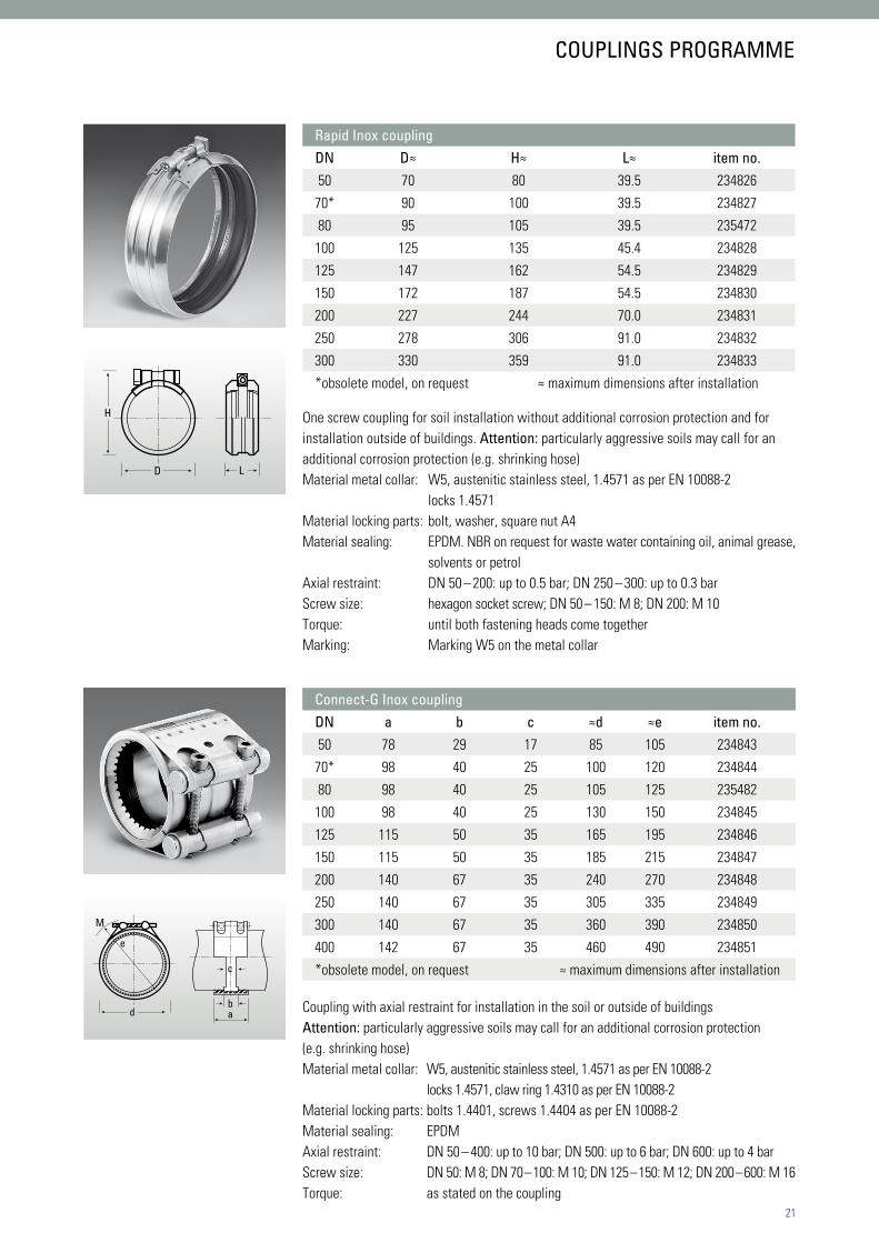
COUPLINGS PROGRAMME
Rapid Inox couplingDN D≈ H≈ L≈ item no.50 70 80 39.5 234826
70* 90 100 39.5 234827
80 95 105 39.5 235472
100 125 135 45.4 234828
125 147 162 54.5 234829
150 172 187 54.5 234830
200 227 244 70.0 234831
250 278 306 91.0 234832
300 330 359 91.0 234833
*obsolete model, on request ≈ maximum dimensions after installation
One screw coupling for soil installation without additional corrosion protection and for installation outside of buildings. Attention: particularly aggressive soils may call for an additional corrosion protection (e.g. shrinking hose) Material metal collar: W5, austenitic stainless steel, 1.4571 as per EN 10088-2 locks 1.4571Material locking parts: bolt, washer, square nut A4 Material sealing: EPDM. NBR on request for waste water containing oil, animal grease, solvents or petrolAxial restraint: DN 50 – 200: up to 0.5 bar; DN 250 – 300: up to 0.3 barScrew size: hexagon socket screw; DN 50 – 150: M 8; DN 200: M 10Torque: until both fastening heads come togetherMarking: Marking W5 on the metal collar
Connect-G Inox couplingDN a b c ≈d ≈e item no.50 78 29 17 85 105 234843
70* 98 40 25 100 120 234844
80 98 40 25 105 125 235482
100 98 40 25 130 150 234845
125 115 50 35 165 195 234846
150 115 50 35 185 215 234847
200 140 67 35 240 270 234848
250 140 67 35 305 335 234849
300 140 67 35 360 390 234850
400 142 67 35 460 490 234851
*obsolete model, on request ≈ maximum dimensions after installation
! !
d
e
c
ba
M
d
e
c
ba
M
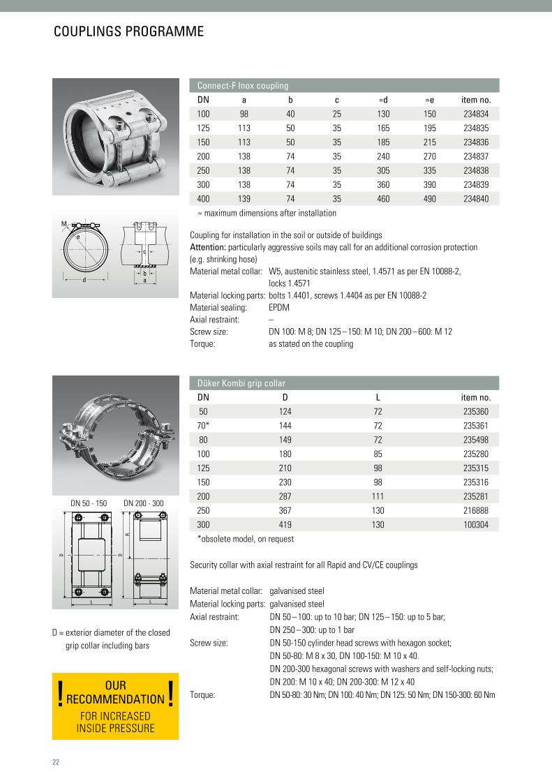
Connect-F Inox couplingDN a b c ≈d ≈e item no.100 98 40 25 130 150 234834
125 113 50 35 165 195 234835
150 113 50 35 185 215 234836
200 138 74 35 240 270 234837
250 138 74 35 305 335 234838
300 138 74 35 360 390 234839
400 139 74 35 460 490 234840
≈ maximum dimensions after installation
Coupling for installation in the soil or outside of buildingsAttention: particularly aggressive soils may call for an additional corrosion protection (e.g. shrinking hose)Material metal collar: W5, austenitic stainless steel, 1.4571 as per EN 10088-2, locks 1.4571 Material locking parts: bolts 1.4401, screws 1.4404 as per EN 10088-2 Material sealing: EPDMAxial restraint: –Screw size: DN 100: M 8; DN 125 – 150: M 10; DN 200 – 600: M 12Torque: as stated on the coupling
DN 50 - 150 DN 200 - 300
Security collar with axial restraint for all Rapid and CV/CE couplings
Material metal collar: galvanised steelMaterial locking parts: galvanised steelAxial restraint: DN 50 – 100: up to 10 bar; DN 125 – 150: up to 5 bar; DN 250 – 300: up to 1 barScrew size: DN 50-150 cylinder head screws with hexagon socket; DN 50-80: M 8 x 30, DN 100-150: M 10 x 40. DN 200-300 hexagonal screws with washers and self-locking nuts; DN 200: M 10 x 40; DN 200-300: M 12 x 40Torque: DN 50-80: 30 Nm; DN 100: 40 Nm; DN 125: 50 Nm; DN 150-300: 60 Nm
D DR
L L
22
Düker Kombi grip collar DN D L item no.50 124 72 235360
70* 144 72 235361
80 149 72 235498
100 180 85 235280
125 210 98 235315
150 230 98 235316
200 287 111 235281
250 367 130 216888
300 419 130 100304
*obsolete model, on request
COUPLINGS PROGRAMME
D = exterior diameter of the closed grip collar including bars
OURRECOMMENDATION
FOR INCREASEDINSIDE PRESSURE

B
D
A
C
B
D
A
C
Security collar with axial restraint for CE dual ring coupling
Material metal collar: galvanised steelMaterial locking parts: galvanised steelAxial restraint: up to 1 barScrew size: hexagonal screw with washers and self-locking nut galvanised M 12 x 40 5.6Torque: 65 – 70 Nm
Two-screw coupling for installation in ceiling penetrations with fire rating
Fire resistance: EI 90 as per classification report no. 0672-901 7132 000/Re/Pk of MPA StuttgartGerman Approval no.: ABZ DIBt Z.19.17-1893Material metal collar: stabilised stainless steel, 1.4510/11 as per EN 10088Material locking parts: galvanised steelMaterial sealing: EPDMMaterial plastic pipe insert: PE-HD / PPMaterial intumescence material: expandable graphite on glass fibre fabric, intumescing at approx. 150°CAxial restraint: –Screw size: M8Torque: 15 Nm
Installation of the coupling similar to Rapid couplings. Fasten the screws alternately and evenly. The upper 20 – 40 mm with the intumescence material strip must be placed in the ceiling; the lower two thirds must protrude below the ceiling (see SML specifier‘s manual).
23
Düker Grip collar DN A D L item no.400 30 460 160 100305
COUPLINGS PROGRAMME
L
DA
Düker fire protection coupling BSV 90DN A≈ B≈ C D≈ ceiling perforation≈ item no.80 106 115 135 125 160 237693
100 133 145 135 140 180 237694
125 160 175 150 155 200 237695
150 188 198 150 170 240 237696 ≈ maximum dimensions after installation

D2
D3
D1
D2
D3
D5
D4
L2L1
L
D2
D3
D1
D2
D3
D5
D4
L2L1
L
D2
D3
D1
D5
D4
L2L1
L
24
For connecting pipes made of PE-HD / PP to cast iron drainage pipes
German Approval no.: Z-42.5-299Material: EPDMMaterial locking parts: W2, worm thread clamp chromium steel 1.4016, screw chrome (VI)-freeAxial restraint: -Screw size: cross-slotted screw, width 7Torque: ca. 2 NmInsertion depth: DN 50: 42 mm; DN 70: 55 mm; DN 80: 55-60 mm; DN 100: 65 mm; DN 125: 75 mm
For connecting pipes of other materials to cast iron drainage pipes, up to three connecting pipes
German Approval no.: Z-42.5-240Material: EPDMMaterial locking parts: worm thread clamp chromium steel 1.4016, screw galvanised steelAxial restraint: -Screw size: worm thread screw SW7Torque: 5.0 + 0.5 Nm
Düker EK Fix couplingDN D1 D2 D3 D4 D5 L L1 L2 connection item no.
50 72 56 30 57 67.5 63 19 40.0 40-56 100270
70* 92 75 41 77 86.5 77 19 52.5 56-75 100271
80 108 75 41 81 91 83 20 52.5 56-75 236756
80 108 90 41 81 91 83 20 55.0 75-90 235346
100 128 110 78 108 118 95 21 65.0 104-110 100272
125 145 125 90 132 145 103 26 72.0 125 100273
*obsolete model, on request
Konfix Multi couplingDN D1 D2 D3 D4 D5 L L1 insertion depth item no.100 134 conn. see illustr. 108 116 90.5 35.5 40 100030
COUPLINGS PROGRAMME

ØD
2
ØD
3
ØD
4
Ød
2
Ød
1
ØD
1
H
Ød
3
Ød
4
DN 70
DN 80
hose74/79 L1
H
D L
Transition coupling for socketless cast iron drainage pipes and fittings DN 70 and DN 80
Material metal collar: W2, stabilised stainless steel, 1.4510/1.4511 as per EN 10088-2 locks 1.4301 or 1.4510/1.4511 Material locking parts: bolt and square nut steel with zinc lamellae coating, washer 1.4301 as per EN 10088-2 Material sealing: EPDMAxial restraint: –Screw size: cylinder head bolt with hexagon socket, M8 Torque: 18 Nm If the locks should touch do not tighten any more.
25
Transition coupling for socketless cast iron drainage pipes DN 100 or old cast iron socket pipes DN 100 with an exterior diameter of max. 115 mm to other materials with an exterior diameter of 72 - 110 mm.
German Approval no.: Z-42.5-240Material: EPDMMaterial locking parts: worm thread clamps chromium steel 1.4061, screw galvanised steelAxial restraint: -Screw size: worm thread screw SW7Torque: 5.0 + 0.5 Nm
Transition couplingDN D≈ H≈ L L1 item no.
70 x 80 96 115 47 30 235347
Multiquick couplingDN Ø D1 Ø D2 Ø D3 Ø D4 Ø d1 Ø d2 Ø d3 Ø d4 H item no.
100 x 70 117 111 101 81 108 104 93 74 107 234859
COUPLINGS PROGRAMME

26
Treatment of pipes
Düker MLK-protec pipes are delivered in three-meter lengths. Just like standard SML pipes, MLK-protec pipes can be cut to fit the required installation lengths. In order not to disrupt the pro-tection coat, the cut pipes must be provided with the cut edge protection Düker pro-cut tape.
Attention: Düker pro-cut tape must be ordered expressly via the wholesaler, it is not delivered automatically with the pipe.
Düker pro-cut tape
Materials: butyl rubber with fluor polyethylene or polypropyl-ene sheet Temperature for installation +5 °C up to +40 °CStorage at +5 °C up to +25 °C
Keep out of the reach of children.
For detailed information, please consult the Technical Data-sheet (see www.dueker.de).
1. cut pipe/fitting and trim any sharp edges and clean the surfaces with an appropriate cloth and alcohol so they are absolutely dry and free of dust and grease. The alcohol must evaporate completely before the application of the tape.
2. cut pro-cut tape to the length of the pipe inside circum-ference (the measurements printed on the tape spool are to be observed), warm the tape slightly (heating or other heat source) and lift off the plastic film.
3. lay the sticky side of the pro-cut tape onto the outside of the cut pipe, at min. 20 mm from the edge.
04 Installation instructions

27
4. draw the pro-cut tape around the pipe with slight and uniform tension, to a slight overlapping. If there is a gap, loosen both sides separately and draw the tape with higher tension until it overlaps.
5. fold the tape from the outside to the inside and press it tightly to the inside surface and the pipe edge. On the inside, the tape must fit without tension.
6. finished cut edge protection. If necessary, apply lubricant to install the coupling. Possibly loosen the coupling screws slightly before pushing it on.
Couplings installation instructions
For the couplings installation instructions, please refer to the latest version of the SML Specifier‘s Manual.
INSTALLATION INSTRUCTIONS

28
Introduction
Pipelines leading to grease traps as well as their ventilation lines are subject to considerable strain due to the grease contained in the waste water. Apart from the chemical attack caused by grease and other components, it is particularly the risk of deposits that must be considered. These deposits are a mechanical load in the pipe, but they also multiply the force of the chemical reactions.
Standards
The layout of supply and ventilation pipelines for grease traps is based mainly on EN 1825-2 as well as EN 12056 and possibly other national and local regulations.
Selection of materials
EN 12056-1 calls for adequate structural and chemical resist-ance of waste water drainage systems. In case of non-domes-tic waste water, the material selection ought to be based on the recommendations of a manufacturer. Düker recommends the MLK-protec drainage pipe system for the supply to the grease trap and the corresponding ventilation lines.
Regarding couplings, EPDM sealings have proven themselves for many years when used with predominantly vegetable grease. Only in case of predominantly animal grease, Düker recommends to use NBR sealings.
Lay-out of the supply line
On principle, grease traps should be placed as close as pos-sible to the point of origin of the grease-containing waste water, in order to keep the supply as short as possible. In order to achieve an adequate flow velocity and self-cleaning of the pipeline, the waste water is to be transported to the grease trap in a slope of at least 2% (1:50). If the pipeline configura-tion is unfavourable due to the building lay-out, or if the supply line has to be quite long, a thermal insulation might be neces-sary in order to prevent grease deposits. However, such an unfavourable pipeline lay-out ought to be avoided whenever possible.
The transition of a down pipe to a horizontal pipe is to be made with a double bend with 250 mm steadying distance, or with a corresponding piece of pipe between to 45° bends. After the transition to the horizontal pipe, another steadying distance is to be observed before connecting to the grease trap, whose length must be at least ten times the nominal diameter (for DN 100: 1000 mm). This is necessary in order to avoid extreme turbulences of water and grease which would impair the effec-tiveness of the grease trap.
The waste water volume Qs in the pipeline leading to the grease trap is calculated as per annex A of EN 1825-2; the dimensioning of the pipeline is then carried out according to EN 12056.
05 Laying instructions Grease drain lines

29
Ventilation and inspection openings
EN 1825-2 says that the pipeline leading to the grease trap is to be ventilated over the roof as a principle; the same applies to each single connecting pipeline with more than 5 m length. If the supply line does not have any such ventilated connecting pipeline on the last 10 m before the grease trap, another ven-tilation must be integrated as closely as possible to the grease line.
German DIN 1986-100 allows to combine the various ventila-tion lines of the supply line, connecting line and even the grease trap itself to be combined to one collecting ventilation line. However, ventilations of other drainage pipelines or that of the waste water lifting plant, which is often installed behind the grease trap, may not be integrated here.
A sufficient number of inspection openings at favourable posi-tions must be installed so the pipeline can be inspected or cleaned fast whenever necessary.
Thermal insulation and heating
The informative annex D of EN 1825-2 gives recommendations as to where thermal insulation or even heating may make sense in order to avoid deposits of grease. Thermal insulation may be necessary where pipelines, particularly longer pipe-lines, cross chilly basements; in case of not frost-free building sections even a heating with insulation is conceivable.
Pipeline trace heatings are recommended for portions of pipe-lines that are subject to frost. In order to save energy, annex D of EN 1825-2 recommends an automatic timer (adjustment range between 25 °C and 40 °C). Furthermore, the elevated costs for installation, operation, and repair of a trace heating must be considered. It is recommended to consult the manufac-turer of the pipe trace heating.
For pipelines that are not subject to frost, the necessity of insulation should be verified in detail. Elevated waste water temperatures in the grease trap impair its effectiveness. Therefore, a certain cooling of the often hot waste water may be desirable.
Example: On a horizontal pipeline of 50 m length in DN 100, with 2% slope and 50% filling level, the waste water has a flow velocity of 1 m/s, so it only takes 50 seconds from the drain to the grease trap. Depending on its original temperature and the ambient temperature, insulation will often be superflu-ous here. However, concrete recommendations are only pos-sible for each individual case.
GREASE DRAIN LINES

30
Undergound installation
31
Selection of material
The product standard EN 877, paragraph 4.8.3.2, contains de-tailed specifications for the required outside coating on cast iron drainage pipe systems installed underground:
„Pipes shall have an outside coating comprising a layer of me-tallic zinc covered by a finishing paint compatible with zinc. (…) When measured, the mean mass of zinc per unit area shall not be less than 130 g/m². (…)
Paragraph 4.8.3.3 says:
„Fittings and accessories shall have a coating (…) of a qual-ity at least equivalent to that of the pipes e.g. (…) epoxy resin based coatings.“
The Düker pipe systems TML, MLK-protec and MLB satisfy these requirements. SML, however, is not suitable for under-ground installation.
In paragraph 4.8.4.1, there are specifications for the materials of couplings in underground installation:
„All parts of couplings or clamping components shall be made of cast iron and coated in accordance with 4.8.3.3, or from austenitic stainless steel in accordance with EN 10088-1, EN 10088-2 and EN 10088-3 with at least 16.5% chrome and 8.5% nickel or equivalent, or from material of comparable resistance“.
The stainless steel collars and clampings of all „Inox“ couplings correspond to these requirements (Rapid Inox, Connect-F Inox, Connect-G Inox). The SVE coupling can be considered a „mate-rial of comparable resistance“. Due to their ease of installation however we recommend to use Rapid couplings.
Attention: CE couplings, which used to be common practice in underground installation, do not consist of a material that is up to the requirements of paragraph 4.8.4.1 of EN 877.
Should any components be installed that do not correspond to paragraph 4.8 of EN 877, these items must be given an on-site corrosion protection e.g. a bituminous wrapping of the manu-facturer Denso.
Soil conditions
The soil aggressiveness is to be determined on the basis of many factors, such as soil type, state, water content, pH value, content in sulphide, sulphate and chloride.
Düker TML, MLK-protec and MLB as well as “Inox” couplings are appropriate for the following soil grades as per German DVGW worksheet GW9:
• Ia (practically not aggressive)• Ib (slightly aggressive)• II (aggressive)
In case of very aggressive soils (soil grade III), an additional corrosion protection such as Denso must be applied to the complete pipeline. The same applies to laying in ground water.
Pipe bedding
Planning and execution of the pipe bedding are to be carried out as per EN 1610 paragraph 7; the German ATV-DVWK work-sheet A139 “Installation and inspection of waste water pipe-lines and canals”, or corresponding local regulations are also to be recommended.
The thickness of the lower bedding layer of compressible mate-rial is at least 100 mm; this value should be increased by one tenth of the pipe diameter. In case of very hard soil, the value is at least 150 mm and should be increased by one fifth of the pipe diameter.
The thickness of the upper bedding layer is to be determined by the specifier.
For couplings, if necessary holes should be provided for in the bedding so the pipeline does not rest on the connections.
UNDERGROUND INSTALLATION

32
Static calculation
The static calculation follows German ATV-DVWK worksheet A127 “Guidelines for the static calculation of waste water pipe-lines and canals”, or local regulations.
Compression of trench filling material
The compression is to be carried out according to EN 1610, paragraph 11 as well as German ATV-DVWK worksheet A139
„Installation and inspection of waste water pipelines and ca-nals“ or corresponding local regulations.
Bearing load
The bearing capacity of cast iron drainage pipes can be deter-mined on the basis of EN 877, annex C.2.
Due to the superior material stability, TML, MLK-protec and MLB can be used for all cover heights including traffic and sur-face loads common in site drainage praxis.
In case of correct and expert installation, a cover height of 0.8 to 6 m and a simultaneous traffic load of SLW 60 can be as-sumed as a guideline.
Leak test The water tightness of underground waste water pipelines must be proven as per EN 1610. The test is prescribed after fill-ing the pipe trench; an additional test before filling is however recommendable, together with a thorough visual inspection of the pipeline.
On principle, the leak test can be carried out with air or with water. Should a test with air fail, a test with water can be done instead. However, we recommend to test with water from the start.
Leak test with air
The leak test with air is to be carried out according to table 3 of EN 1610. The German plumbers’ association ZVSHK recom-mends the test method LC with a test pressure of 100 mbar, an admissible pressure loss of 15 mbar, and a test duration of 3 to 8 minutes depending on the pipeline diameter.
At first, the pressure is kept up by adding air. This period serves to compensate for temperature differences in the air added. After that, no more air is added and the pressure loss after a defined period of time is measured.
For measuring, electronic devices or the U-pipe-manometer have proved themselves.
Leak test with water
The test can be carried out on the complete pipeline or on defined pipeline sections.
At first, the length of the pipeline must be determined, in order to calculate the inner surface and the admissible quantity of water to be added.
The test pressure is to be calculated as per the pressure of a water column from the pipe crest of the section to be tested up to the ground level, e.g. 2.5 m = 25 kPa (250 mbar). The test pressure is minimum 10 kPa, maximum 50 kPa.
UNDERGROUND INSTALLATION
33
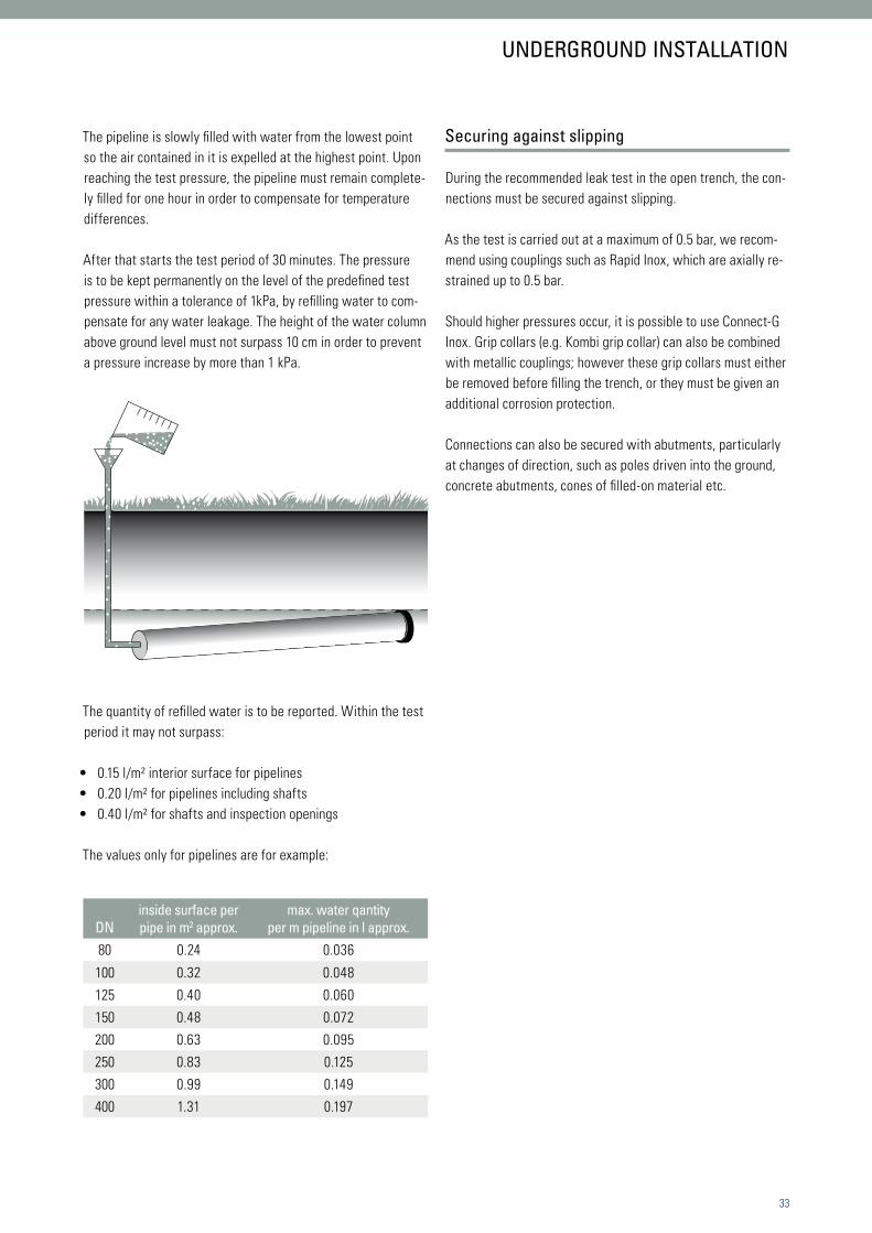
The pipeline is slowly filled with water from the lowest point so the air contained in it is expelled at the highest point. Upon reaching the test pressure, the pipeline must remain complete-ly filled for one hour in order to compensate for temperature differences.
After that starts the test period of 30 minutes. The pressure is to be kept permanently on the level of the predefined test pressure within a tolerance of 1kPa, by refilling water to com-pensate for any water leakage. The height of the water column above ground level must not surpass 10 cm in order to prevent a pressure increase by more than 1 kPa.
The quantity of refilled water is to be reported. Within the test period it may not surpass:
• 0.15 l/m² interior surface for pipelines • 0.20 l/m² for pipelines including shafts • 0.40 l/m² for shafts and inspection openings
The values only for pipelines are for example:
Securing against slipping
During the recommended leak test in the open trench, the con-nections must be secured against slipping.
As the test is carried out at a maximum of 0.5 bar, we recom-mend using couplings such as Rapid Inox, which are axially re-strained up to 0.5 bar.
Should higher pressures occur, it is possible to use Connect-G Inox. Grip collars (e.g. Kombi grip collar) can also be combined with metallic couplings; however these grip collars must either be removed before filling the trench, or they must be given an additional corrosion protection.
Connections can also be secured with abutments, particularly at changes of direction, such as poles driven into the ground, concrete abutments, cones of filled-on material etc.
DNinside surface per pipe in m2 approx.
max. water qantity per m pipeline in l approx.
80 0.24 0.036
100 0.32 0.048
125 0.40 0.060
150 0.48 0.072
200 0.63 0.095
250 0.83 0.125
300 0.99 0.149
400 1.31 0.197
UNDERGROUND INSTALLATION

34
Drainage pipe system – Düker – MLK-protec system
no. qty. item unit price amount
Socketless cast iron drainage pipes and fittings, approved and manufactured as per EN 877, dimensions as per DIN 19 522, with protec special coating , with CE marking and Declaration of Performance as per CPR.
Short name: Düker MLK-protec pipes and fittings
Pipes inside with a double, fully cross-linked two-component epoxy coat-ing outside with zinc coat and a grey epoxy cover coating, fittings inside and outside with powder epoxy coating.
Range of products DN 50 – 400 as per the latest price-list. Resistance as per the latest resistance chart.
Installation: As per Düker installation instructions and in accordance with the technical regulations of of EN 12056 / DIN 1986 part 100 / EN 752, EN 1610.
Handling instructions: cut ends are to be protected with the Düker cut-edge protection pro-cut tape.
Couplings: Dükorapid®, Dükorapid® Inox, Rapid Inox, Connect-F Inox coupling,
Connect-G Inox coupling, Düker EK Fix coupling Z-42.5-299 or Konfix-Multi coupling Z-42.5-240 and Multiquick coupling Z-42.5-240 for connection to pipes, fittings and other elements (e.g. floor drain) made of other materials to MLK-protec. The securing of pipelines with the risk of internal pressure and axial restraint require grip collars or Connect couplings. Couplings and grip collars are paid for separately
1 mtrs. Düker MLK-protec pipes in trade lengths of 3000 mm, DN .......,
including cutting to length, supply and installation
material: wages:
2 spools Düker pro-cut tape for cut edge protection, in trade lengths of 10 m or 20 m, supply and installation
material: wages:
06 Specifying texts
35
no. qty. item unit price amount
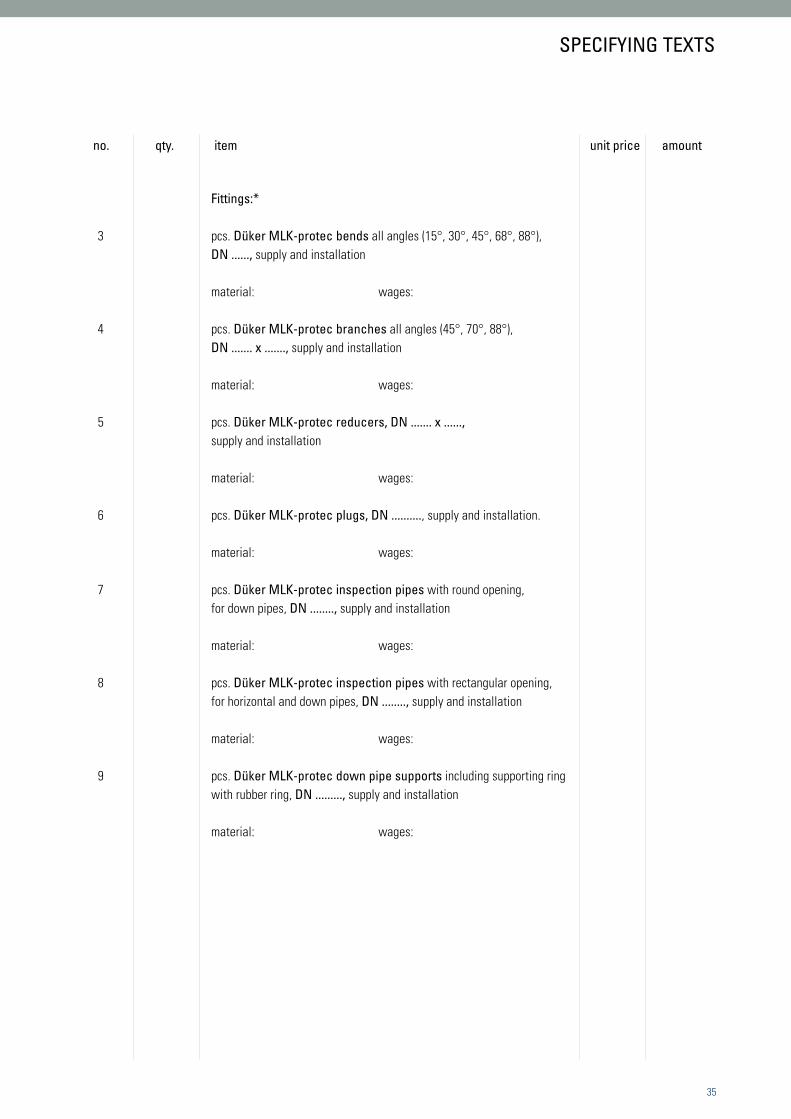
Fittings:*
3 pcs. Düker MLK-protec bends all angles (15°, 30°, 45°, 68°, 88°), DN ......, supply and installation material: wages: 4 pcs. Düker MLK-protec branches all angles (45°, 70°, 88°), DN ....... x ......., supply and installation material: wages: 5 pcs. Düker MLK-protec reducers, DN ....... x ......, supply and installation material: wages: 6 pcs. Düker MLK-protec plugs, DN .........., supply and installation. material: wages: 7 pcs. Düker MLK-protec inspection pipes with round opening, for down pipes, DN ........, supply and installation material: wages: 8 pcs. Düker MLK-protec inspection pipes with rectangular opening,
for horizontal and down pipes, DN ........, supply and installation
material: wages: 9 pcs. Düker MLK-protec down pipe supports including supporting ring
with rubber ring, DN ........., supply and installation material: wages:
SPECIFYING TEXTS

36
no. qty. item unit price amount
10 pcs. Dükorapid® couplings***, metal collar made of stabilised chromium steel, material no. 1.4510/11 as per EN 10088, lock with only one screw, locking plates made of material no. 1.4301 as per EN 10088; screw and square nut steel with zinc lamellae coating, washer A2. Seal-ing collar made of EPDM, DN ........, supply and installation.
material: wages:
11 pcs. Dükorapid® Inox couplings, metal collar and lock made of material no. 1.4404 as per EN 10088, lock with only one bolt, bolt, square nut and washer steel A4. Sealing collar made of EPDM, DN ........, supply and installation.
material: wages: 12 pcs. Rapid Inox couplings**, lock with only one screw, all parts made
of material no. 1.4571/1.4401 as per EN 10088, sealing collar made of EPDM**, DN ........, supply and installation.
material: wages: 13 pcs. Connect-F Inox couplings, metal collar made of material no. 1.4571, locking parts made of material no. 1.4401, screws made of material no. 1.4404, sealing collar made of EPDM, DN ............., supply and installation. material: wages: 14 pcs. Connect-G Inox couplings, coupling with axial restraint, metal
collar made of material no. 1.4571, locking parts made of material no. 1.4401, screws made of material no. 1.4404, claw ring made of material no. 1.4310, sealing collar made of EPDM, DN ............., supply and installation. material: wages: 15 pcs. Düker EK Fix couplings, approval no. Z-42.5-299, made of EPDM,
including clamp straps, for connection of pipes made of other materials to MLK-protec, DN ............., supply and installation.
material: wages: 16 pcs. Konfix Multi couplings, approval no. Z-42.5-240 made of EPDM,
including clamp straps, for connection of pipes made of other materials to MLK-protec, DN 100, supply and installation.
material: wages:
SPECIFYING TEXTS

37
no. qty. item unit price amount
17 pcs. Multiquick couplings, approval no. Z-42.5-240 made of EPDM, including clamp straps, for connection of pipes made of other materials to MLK-protec, DN 100, supply and installation.
material: wages: 18 pcs. Kombi grip collars***, securing grip collar with axial restraint for
Dükorapid® and Rapid Inox couplings as well as CV and CE couplings on pipelines subject to inside pressure, DN ........., supply and installation.
material: wages:
*for further fittings please refer to the product range
** if applicable the rubber quality is to be modified to NBR.
*** this coupling must be equipped with an additional corrosion protection in case of soil installation.
SPECIFYING TEXTS

38
NOTES

39
NOTES

40
239375 / 03.18 Specifications subject to change without notice.
Düker GmbH
Würzburger Straße 10-16D-97753 Karlstadt /Main
Germany
Phone +49 9353 791-570Fax +49 9353 791-8570
Internet: www.dueker.deE-Mail: [email protected]
DRAINAGE TECHNOLOGY
GLASS LINING TECHNOLOGIES
JOBBING FOUNDRY
FITTINGS AND VALVES