Mixed-Convective, Conjugate Heat Transfer During Molten Salt … · Mixed-Convective, Conjugate...
27
SANDIA REPORT SAND97-8234 “ UC-406 Unlimited Release . ‘ Printed February 1997 Mixed-Convective, Conjugate Heat Transfer During Molten Salt Quenching of Small Parts D. R. Chenoweth 9 . $
Transcript of Mixed-Convective, Conjugate Heat Transfer During Molten Salt … · Mixed-Convective, Conjugate...

SANDIA REPORTSAND97-8234 “ UC-406Unlimited Release.
‘ Printed February 1997
Mixed-Convective, Conjugate Heat TransferDuring Molten Salt Quenching of Small Parts
D. R. Chenoweth
9.
$
issued by Sandia National Laboratories, operated for the UnitedStates Department of Energy by Sandia Corporation.NOTICE: This report was prepared as an account of work sponsoredby an agency of the United States Government. Neither the UnitedStates Government nor any agency thereof, nor any of theiremployees, nor any of the contractors, subcontractors, or theiremployees, makes any warranty, express or implied, or assumes anylegal liability or responsibility for the accuracy, completeness, orusefulness of any information, apparatus, product, or processdisclosed, or represents that its use would not infringe privatelyowned rights. Reference herein to any specific commercial product,process, or service by trade name, trademark, manufacturer, orotherwise, does not necessarily constitute or imply its endorsement,recommendation, or favoring by the United States Government, anyagency thereof or any of their contractors or subcontractors. Theviews and opinions expressed herein do not necessarily state orreflect those of the United States Government, any agency thereof,or any of their contractors or subcontractors.
..
f
SAND97-8234Unlimited Release
Printed February 1997
UC-406
Mixed-Convective, Conjugate Heat Transfer during Molten SaltQuenching of Small Parts
D. R. ChenowethSandia National Laboratories
suMMARY
It is common in free quenching immersion heat treatment calculations to locally apply.constant or surface-averaged heat-transfer coefficients obtained from either free or forced steadyconvection over simple shapes with small temperature differences from the ambient fluid. Thisprocedure avoids the solution of highly transient, non-Boussinesq conjugate heat transfer problems
d which ofien involve mixed convection, but it leaves great uncertainty about the general adequacy ofthe results. In this paper we demonstrate for small parts (dimensions of the order of inches ratherthan feet) quenched in molten salt, that it is feasible to calculate such non-uniform surface heattransfer from first principles without adjustable empirical parameters. We use literature physicalproperty salt data from the separate publications of Kirst et al., Nissen, Carling, and Teja, et al. forTc1OOOF, and then extrapolate it to the initial part temperature. The reported thermal/chemicalbreakdown of NaN02 for T>800 F is not considered to be important due to the short time thesurface temperature exceeds that value for small parts. Similarly, for small parts, the localReynolds and Rayleigh numbers are below the corresponding critical values for most if not all ofthe quench, so that we see no evidence of the existence of significant turbulence effects, only somelarge scale unsteadiness for brief periods. The experimental data comparisons from the openliterature include some probe cooling-rate results of Foreman, as well as some cylinder thermalhistories of Howes.
3/4

.
.
.8!
Introduction . . . . . . . . . . . . . . . . . . . . . . . . . . . . . . . . . . . . . . . . . . . . . . . . . . . . . . . . . . . . . . . . . . . . . . . . . . . . . . . . . . . . . . . . . . . . . 9
Computational Methods . . . . . . . . . . . . . . . . . . . . . . . . . . . . . . . . . . . . . . . . . . . . . . . . . . . . . . . . . . . . . . . . . . . . . . . . . . . . . . . . 9
Physical Properties . . . . . . . . . . . . . . . . . . . . . . . . . . . . . . . . . . . . . . . . . . . . . . . . . . . . . . . . . . . . . . . . . . . . . . . . . . . . . . . . . . . .10
Thermal Decomposition Of Quenchant Components . . . . . . . . . . . . . . . . . . . . . . . . . . . . . . . . . . . . . . . . . . . . . . 14
Mixed Convection And Turbulence . . . . . . . . . . . . . . . . . . . . . . . . . . . . . . . . . . . . . . . . . . . . . . . . . . . . . . . . . . . . . . . . .14
Discussion Of Results . . . . . . . . . . . . . . . . . . . . . . . . . . . . . . . . . . . . . . . . . . . . . . . . . . . . . . . . . . . . . . . . . . . . . . . . . . . . . . . . .16
Related Publications in Preparation . . . . . . . . . . . . . . . . . . . . . . . . . . . . . . . . . . . . . . . . . . . . . . . . . . . . . . . . . . . . . . . . . .23
References . . . . . . . . ..e . . . . . . . . . . . . . . . . . . . . . . . . . . . . . . . . . . . . . . . . . . . . . . . . . . . . . . . . . . . . . . . . . . . . . . . . . . . . . . . . . . .25
5/6

.
LIST OF FIGURES
.
Figures la, lb Foreman Quarter Inch SS Probe, Small Immersion Rate
Figure 2 Foreman Quarter Inch SS Probe, Parameter Immersion Rate
Figure 3 Skidmore/Gulf Half Inch SS Cylinder, L/I)= 3
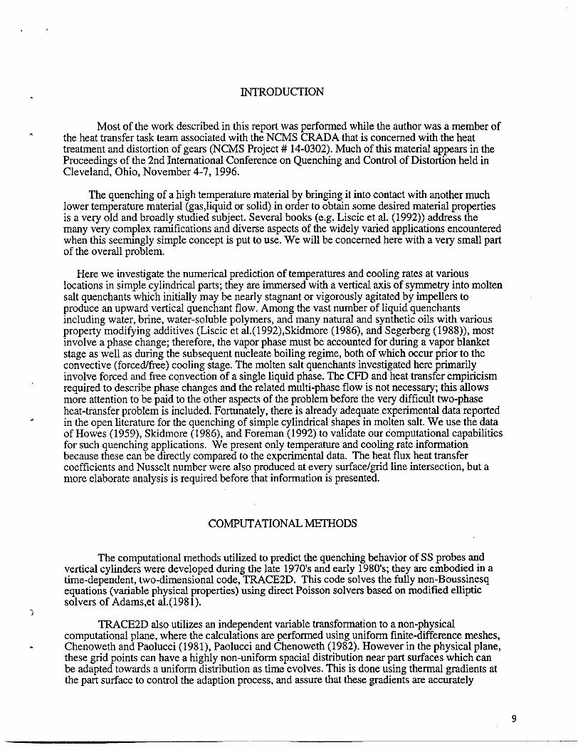
Figures 4a,4b Howes One Inch SS Cylinder, L/D= 2, V = 0.0 and 25.4 cmkec
Figures 5a,5b Howes Two Inch SS Cylinder, L/I)= 2, V = 0.0 and 25.4 crn/sec
Figures 6a,6b Howes Three Inch SS Cylinder, LID= 2, V = 0.0 and 25.4 cmlsec
7/8

. INTRODUCTION
Most of the work described in this report was performed while the author was a member of.the heat transfer task team associated with the NCMS CRADA that is concerned with the heattreatment and distortion of gears (NCMS Project # 14-0302). Much of this material appears in theProceedings of the 2nd International Conference on Quenching and Control of Distortion held inCleveland, Ohio, November 4-7, 1996.
The quenching of a high temperature material by bringing it into contact with another muchlower temperature material (gas,liquid or solid) in order to obtain some desired material propertiesis a very old and broadly studied subject. Several books (e.g. Liscic et al. (1992)) address themany very complex ramifications and diverse aspects of the widely varied applications encounteredwhen this seemingly simple concept is put to use. We will be concerned here with a very small partof the overall problem.
Here we investigate the numerical prediction of temperatures and cooling rates at variouslocations in simple cylindrical parts; they are immersed with a vertical axis of symmetry into moltensalt quenchants which initially maybe neady stagnant or vigorously agitated by impellers toproduce an upward vertical quenchant flow. Among the vast number of liquid quenchantsincluding water, brine, water-soluble polymers, and many natural and synthetic oils with variousproperty modi~ing additives (Liscic et al.(1992),Skidmore (1986), and Segerberg (1988)), mostinvolve a phase change; therefore, the vapor phase must be accounted for during a vapor blanketstage as well as during the subsequent nucleate boiling regime, both of which occur prior to theconvective (forced/free) cooling stage. The molten salt quenchants investigated here primarilyinvolve forced and free convection of a single liquid phase. The CFD and heat transfer empiricismrequired to describe phase changes and the related multi-phase flow is not necessary; this allowsmore attention to be paid to the other aspects of the problem before the very difficult two-phaseheat-transfer problem is included. Fortunately, there is already adequate experimental data reported
. in the open literature for the quenching of simple cylindrical shapes in molten salt. We use the dataof Howes (1959), Skidmore (1986), and Foreman (1992) to validate our computational capabilitiesfor such quenching applications. We present only temperature and cooling rate informationbecause these can be directly compared to the experimental data. The heat flux heat transfercoefficients and Nusselt number were also produced at every surface/grid line intersection, but amore elaborate analysis is required before that information is presented.
COMPUTATIONAL METHODS
The computational methods utilized to predict the quenching behavior of SS probes andvertical cylinders were developed during the late 1970’s and early 1980s; they are embodied in atime-dependent, two-dimensional code, TRACE2D. This code solves the fully non-Boussinesqequations (variable physical properties) using direct Poisson solvers based on modified ellipticsolvers ofAdams,etal.(1981).
.,!
TRACE2D also utilizes an independent variable transformation to a non-physicalcomputational plane, where the calculations are performed using uniform finite-difference meshes,
. Chenoweth and Paolucci (198 1), Paolucci and Chenoweth (1982). However in the physical plane,these grid points can have a highly non-uniform spatial distribution near part surfaces which canbe adapted towards a uniform distribution as time evolves. This is done using thermal gradients atthe part surface to control the adaption process, and assure that these gradients are accurately
9

resolved at early time where they are largest. This procedure has allowed TRACE2D to bemodified to describe parts of simple shape (arbitrary aspect ratio cylinders and rings) which areplaced in motion vertically to simulate actual immersion processes.
TRACE2D has also been generalized to include conjugate heat transfer between finite solidparts and a surrounding liquid quenchant. Thus the heat-transfer process between the part, whereconduction is dominant, and the quenchant, where mixed convection (including arbitrary relativeamounts of free and forced convection) maybe present, is fully coupled. There are no simplifyingassumptions other than acoustic wave filtering in the quenchant flow equations. That is, thecompressible Navier-Stokes equations which are solved by TRACE2D are simplified only by thesmall Mach number approximation. This allows the time-step limitation for numerical stability ofexplicit finite-difference methods to be greatly enlarged. This is accomplished without anyappreciable penalty provided the quenchant velocity squared is always much smaller than the localsound speed squared.
The entire procedure was fully validated using air in the free convection regime inChenoweth and Paolucci (1985, 1986a, 1986b, 1987), and Paolucci and Chenoweth (1988), forlaminar flow, where the Rayleigh number,Ra, remained less than 108. It was also validated in thetransition region where 108< Ra <1010, during which unsteady periodic motion progressedtoward fully chaotic motion as turbulent motion was approached, Paolucci and Chenoweth (1989).Finally, TRACE2D was used to predict the effects of fully turbulent motion by Paolucci (1990),where Ra = 101O.This validation process is important because it is found that comparable Rayleighnumbers are encountered here, but usually in the mixed convection region where the Reynoldsnumber also plays a key role.
PHYSICAL PROPERTIES
The temperature dependent physical properties for mild steel and stainless steel are obtainedfrom Bogaard and Desai (1994) and Touloukain and Ho (1977), respectively.
Many molten salt quenchants consist of various binary and ternary mixtures of KNO~,NaNO~ and NaN02; each of these pure components are not as useful separately due to theirrelatively high nominal freezing points of 607, 582 and 556K, respectively. Therefore physicalproperties of the pure components will not be given or discussed here unless the “linear molarmixing rule” (LMMR) has been proven to be valid and useful for mixture property estimates whendirect experimental mixture measurements are lacking. Kirst, et al. “(1940) showed that the largestsingle effect obtained by blending these components is the greatly reduced mixture freezing point(e.g. as low as 412K for equal weights of KNOj and NaNOJ. The other physical propertiesrequired for CFD analysis of molten salt quenching include mixture viscosity, density, heatcapacity and thermal conductivity and they are not so greatly altered by the mixture content. Thisobservation is, however, based on the apparent existence of substantial experimental data for onlytwo popular blends, one binary and the other ternary. The ternary mixture, Kirst, et al.( 1940) wasoriginally sold under the tradename HTS and is now called HITEC (similar to PARTHERM 290)and nominally consists of 53wt% KNO~, 7wt% NaNOq and 40wt% NaNOz with a freezing pointof about416K. This blend’s experimental data will be considered representative of all “lowoperating temperature salts’’(LOTS) for lack of any other evidence. The binary mixture isnominally an equimolar (near eutectic) blend of the nitrates KNO~ and NaNO~, with a melting pointof about 495K. This blend is similar to PARTHERM 430, and it will be considered to berepresentative of all “high operating temperature salts’’(HOTS) for lack of any other complete set ofmixture data. The HOTS higher temperature range often restricts it to austempering applications,

while the LOTS wider temperature range allows it to be used for both martempering andaustempering in many cases.
.
In spite of the very good early work by Kirst, et al.(1940) and later by Janz,et al.(1979),from a CFD point of view, a number of problems remain with respect to the use of molten salts as
. quenchants in heat treatment applications. Much of the difficulty appears to stem from the fact thatother heat transfer applications than heat treatment have driven much of the molten salt research,and those applications involve a more limited temperature range in most cases. The temperaturedependent physical properties are required over the entire range from ambient quenchanttemperature up to the initial part surface temperature for CFD analysis of quenching applications.Unfortunately viscosity and density data exist only for T < 875K. Worse yet, the experimental datafor heat capacity and thermal conductivity is even more limited and generally never exceeds 750K.Until higher temperature data is available, this leaves little choice other than extensive propertyextrapolations to reach some reasonable estimates near the part surface temperature. Such aprocedure requires that great attention be paid to the low temperature data. We will return to thisdiscussion following a brief summary of available physical property molten salt mixture data,because there are also other factors involved.
Kirst, et al. (1940) give the LOTS viscosity in tabular form for 422< T(K)< 709. Nissen(1982) gives the HOTS viscosity for 573< T(K)< 873 in the form of a cubic fit in T, which is notsuitable for extrapolation to higher T values. Both data sets, however, can be well represented by
p(poises) = 0.00457 exp[(800/T(K))2] (1)
which can be used to extend to higher temperatures until some data becomes available there. Thestrongest property temperature dependence (non-Boussinesq behavior) is injected into the CFDresults by this viscosity expression. Nissen (1982) detected little effect on viscosity from the
d addition of up to 40mol% KNOZ to an equimolar mixture of NaNOj and KNO~.
Kirst, et al. give the LOTS density for 422 c T(K) <828 which appears to be nearly linearin T and well described by
p(g/cm3) = 2.283-0.000715 T(K), (2)
while Nissen (1982) gives the HOTS density as
p(g/cm3) = 2.264-0.000636 T(K). (3)
Although very similar, these results do show that apparently the coefficient of thermal expansion
P = -(dp/dT)/p is substantially greater for LOTS than for the HOTS mixture. Nissen (1982).
shows that the addition of up to 40mol% KN02 to an equimolar mixture of the nitrates primarilyalters the intercept, and has little effect on the slope or the coefficient of T.
11

Heat Ca~acitv:
Kirst, et al. give the LOTS heat capacity to be about constant, Cp = 0.373 cal/g K. Using aLMMR, the values of 0.333 cal/g K for KNO~ and 0.399 cal/g K for NaNO~, obtained by Carling(1983) and Takahashi, et al.(1988) in a narrow T range following their melting, are consistent withthis LOTS mixture value provided Cp = 0.405 cal/g K for NaNOz. This value is in good agreementwith Janz and Truong (1983) who reported it decreasing from 0.414 to 0.409 as T increased from570 to 670K. Furthermore the LMMR predicts 0.366 callg K for the HOTS heat capacity. Thelarger T range used by Carling also showed some decrease in Cp with increasing T, especially forT > 650-750K, a region not covered by Takahashi, et al. Such a temperature dependence would beconsistent with the suggestion by Tufeu, et al.( 1985), that Cp can be estimated for all sodium andpotassium nitrates and nitrites using a nearly constant thermal diffusivity
a = k/pCp = 0.0016 cm2/sec.
Thus decreasing Cp with increasing T would be true only if the thermal conductivity, k, has a
negative T slope which is greater than that of the density, p already given, and provided that
u = k/pCp really is about constant. We will return to this estimate of Cp following the discussionof thermal diffusivity and thermal conductivity.
Thermal Diffusivitv:
The validity of the procedure just mentioned is difficult to prove since it is the T
dependence of k and u which has been the most difficult to confirm. Both large positive andnegative T slopes have been reported in the literature since 1952. In some cases investigators have
in fact assumed constant heat capacity and then used a = k/pCp to infer either k or a behaviorfrom the measurements of the other. During the last two decades it has been reported somewhatconsistently that the thermal diffusivity increases with increasing T, while thermal conductivity
appears to have a weak decrease with T. These small positive and negative slopes with T for a andk, respectively, have been reported for fairly narrow T ranges. Thus if extrapolated to the part T,they can still represent significant effects.
Neither Kirst, et al. nor Nissen report any thermal diffusivity or conductivity data.
Obviously both cxand k are not needed for CFD if p, p and Cp are available. However information
on both ~ and k does allow a valuable internal consistency check, especially with respect to Tdependence.
Ohta, et al.( 1990) show for NaNOJ that et increases from about 0.0014 to 0.0015 cm2/sec
as T increases from 593 to 660K, while for KNO~ et increases from about 0.0015 to 0.0016cm2/sec as T increases from 621 to 694K. Some of the same authors (Otha and Waseda) appear toreport data by the same experimental method on the same materials in Waseda, et al.( 1992), butwith significantly higher magnitudes, 0.001 !3to 0.0021 cm2/sec for both KNO~ and NaNO~,
without explaining the apparent differences. Kate, et al.( 1983) find that ct is about constant forKNO~ at about 0.00169 cm2/sec and similarly for NaNO~ at about 0.00172 cm2/sec. Odawara, et
al.( 1977) also report a for NaNO~ to be about constant for581 < T(K) <691, u = 0.00169
cm21sec, but for LOTS they find that ct increases from 0.00168 to 0.00181 cm2/sec as T increasesfrom 440 to 692K.
12

.
cx(cm2/see) = 0.001 [ 1.45 + 0.000516 T(K) ] (4)
f+
Thermal Conductivity:
Odawara, et al.(1977) also use constant Cp for that thermal diffusivity T range, with
density linearly dependent on T, to estimate k = (x p Cp for LOTS to be
k(w/rn/K) = 0.5385-0.000047 T(K) (5)
so that had Cp also decreased with T, the very weak T slope of this k would have beenstrengthened somewhat. Omotani, et al.(1982) used various mixtures of KNO~ and NaNOq toestablish that thermal conductivity appears to follow a LMMR. For the HOTS (equimolarmixture), a slightly negative T dependence was obtained
k(w/rn/K) = 0.5461-0.000169 T(K) (6)
for 498< T(K)< 593. Omotani, et aI.(1984) gave a comparable result for the LOTS (ternarymixture)
k(w/m/K) = 0.5163-0.000038 T(K) (7)
for 427< T(K)< 584, showing even weaker dependence on T than for HOTS, similar to that ofOdawara, et al.(1977)..
The results of Tufeu, et al.(1985) are in substantial agreement with Omotani, et al. forHOTS; however, they obtained a slightly positive T dependence
.
k(w/m/K) = 0.4541 + 0.00058 T(K) (8)
for LOTS.
Kitade, et al.(1989) give results for pure NaNO~ and pure KNO~ in the narrow T ranges584< T(K) e 662 and 622 e T(K) <712, respectively. If these results are combined with aLMMR for the equimolar case,
k(w/rn/K) = 0.6239-0.000265 T(K) (9)
for HOTS.
More recently DiGuilio and Teja (1992) gave similar results for HOTS for525< T(K)< 590,
k(w/m/K) = 0.635-0.000317 T(K) (lo).
which is very similar to the expression just obtained from Kitade, et al. results above. Werecommend and use this expression from DiGuilio and Teja results for HOTS (high operating
. temperature salts) for near equimolar mixtures of KNO~ and NaNO~. For LOTS (low operatingtemperature salts) consisting of ternary mixtures similar to HTS(HITEC) we recommend and usethe expression (5) which Odawara, et al. estimated from their thermal diffusivity results via a least
13
squares fit. That expression has coefficients whose percentage increase over the lower values ofOmotani, et al. have the same ratio 5.5 as those of DiGuilio and Teja when compared to Omotani,et al. results for HOTS. That is, we are assuming comparable systematic errors for both LOTS
and HOTS in the Omotani, et al. results. Therefore, for HOTS, u = 0.0016 cm2/see, a constant,and
Cp(cal/g/K) = Ic/ap = 0.419 [ 1.0-0.0005 T(K) ]/ [ 1.0-0.000281 T(K) ] (11)
which decreases about 5% as T increases from 500 to 650K. For LOTS, Cp(cal/g/K) = kktp =
0.376, a constant and
ct(cm2/see) = 0.001 [ 1.45 + 0.000516 T(K) ] (12)
gives a fully consistent set of physical properties, considering the limited temperature range as well
as the considerable scatter in much of the experimental results fork and U.
THERMAL DECOMPOSITION OF QUENCHANT COMPONENTS
It is well known, Kirst, et al.(1940) that LOTS undergoes a thermal decomposition above700K, In this ternary mixture, it is the nitrite which is most unstable, breaking down to nitrate,oxide and nitrogen gas at a rate which increases with temperature. Fortunately, according toBradshaw and Meeker (1995), the mixture adjacent to the part surface must remain above thisbreakdown temperature for periods greater than about a minute, in order for enough decomposition “to occur to significantly affect physical properties. Therefore the quenching of small parts is notexpected to show the effects of this decomposition, even though larger parts with dimensions ofthe order of feet would be susceptible to such effects. It is also well known, Nissen (198 1), that -/the nitrates in the HOTS binary mixture breakdown slowly above 800K into nitrites and oxygengas, among other products. This decomposition is even weaker than the nitrite breakdown inLOTS, so one would also expect it to be unimportant for parts of small dimensions.
MIXED CONVECTION AND TURBULENCE
When both free and forced convection are present, the Richardson number Ri = Gr/Re2
controls much of the flow behavior. Here, Gr = g 13AT L3 / (y/p)* is the Grashof number, and
Re = p V L / u is the Reynolds number in terms of the forced convection velocity, V, and the
difference between the initial part and ambient quenchant temperature, AT. Forced convection isdominant if Ri <<1, and free convection is dominant if Ri >>1. For molten salt near ambienttemperatures between 450-500K
Ri = 225 L(cm) / V(cm/sec)2
.
so that Ri = 1 implies that the modes of convection have extensive interaction when V(cm/see) = 15L(cm)05, where L represents a characteristic part dimension. If the combined velocity fields from

immersion and agitation are significantly less than this magnitude, they will not be effective inaltering the free convection heat transfer distribution; conversely, if they greatly exceed this value,.the results will bear little resemblance to that free convection limit.
*, Forced Convection:
A forced convection dominated flow, Ri <<1, will exhibit Iaminar boundary layer flow(little wall generated turbulence) in ambient molten salt if
Re = 30 L(cm) V(crn/see) <105.
The region 105< Re c 106is often referred to as the transition region, and filly developedturbulence would usually not occur unless Re >106, and enough time elapses at that level in orderfor it to develop chaotic motion which includes a full spectrum of frequencies and spatial scales.This indicates that for most parts with dimensions less than one foot, there will be little wallgenerated turbulence when Ri <<1 provided V <100 cmlsec, or more generallyV(cm/see) < 3300/ L(cm). Of course even when transition to turbulence does occur, it will occurlocally only after the distance along the surface has exceeded the critical value for a given value ofvelocity. These results are altered somewhat by temperature dependent salt properties as will bediscussed briefly below. Also free stream turbulence that is being generated by impellers or otherdevices is entirely another matter, and it must be included by other means. The forced convectionvelocity boundary layer thickness, f, grows with distance,s, in the larninar regime like
f(cm) = J [s(cm)/ V(cm/see)] which gives a measure of the spatial resolution required whennumerical methods are employed to predict such behavior during quenching. A minimum of 3-5mesh points are needed inside this boundary layer thickness in order to resolve or describe velocitybehavior near the part surface. The thermal boundary layer, which controls the heat flux, can be.estimated to be even smaller than that for the velocity by a factor l/Pr033 when the Prandtl numberis greater than unity.
*
Free Convection:
When the combined effects of agitation and immersion result in Ri >>1, then freeconvection or buoyant thermal effects control the heat transfer processes. The transition toturbulence is then a much more complex issue. The transition region for vertical surfaces generallyoccurs for 108c Ra < 5X10⁹,while on upward facing horizontal surfaces it may occur for3X105< Ra <108. Extensive downward facing surfaces may never reach a transition region at allunless they are interacting strongly with some adjacent vertical surface. Here the Rayleigh number
Ra = Pr Gr where Pr = p / a p is the Prandtl number. In terms of the ambient salt properties, Ra is
approximately Ra = 7000 AT(K) L(cm)3 in terms of a charactistic part reference length L and the
temperature difference, AT,between the initial part and the ambient quenchant values. Thus evenfor nominal dimensions of a few centimeters, the transition region might be present on the upperportions of the part. Furthermore, the velocity boundary layer thickness is of the order of
. f(cm) = 0.13 [ s(cm) / AT(K) ]02’
which grows less rapid with distance along the surface than the forced convection case. Obviously. for large temperature differences, this boundary layer can be very thin, so that mesh spacing near
the surface can be required to be very small in order to properly resolve the velocity andtemperature gradients encountered there during quenching.
15

Temperature De~endence:
The temperature dependence of the molten salt physical properties, in particular theexponential drop in viscosity with increasing temperature, significantly modifies the picture of
transition to turbulence just described. The Prandtl number Pr = p/ap drops from around 20 to 30in the ambient salt to around 2 to 3 near the hot part surface early in the quench. Since the Pecletnumber is Pe = Pr Re and the Rayleigh number is Ra = Pr Gr, one would expect considerablestabilizing influence due to this order of magnitude reduction in viscous effects relative to thermaleffects in the thin boundary layer compared to their values outside of that region. Although Ra stillincreases greatly with increasing T, that increase is much less than that of Gr due to the effect ofthe large Pr decrease. Similarly, the large increase in Re with increasing T is virtually eliminated bythe Pr decrease when Pe is calculated.
This stabilizing effect of a thin layer of much less viscous fluid between a solid wall and amuch more viscous fluid is well known; it has been studied for Couette flow by Renardy (1987),and for Poiseuille flow by Pinarbasi and Liakopoulos (1996). It is sometimes referred to as the“thin layer effect” or as “lubrication stabilization” and it can greatly delay transition to turbulence.This same effect can also greatly alter mixed convective behavior, such that a flow which would beturbulent in free convection, can be partially laminarized by the additional influence of forcedconvection when it is added to the problem, Inagaki (1996) and Jackson, et al.( 1994). In factKitamura and Inagaki (1987) found that on a vertical heated flat plate with forced upward waterflow, the “turbulence suppression” is so great that the mixed convection heat transfer coefficient orNusselt number can be lowered by as much as 25~0 compared to that from either pure forced orpure free convection with comparable parameters.
DISCUSSION OF RESULTS
Foreman (1992) gave the center temperature and cooling rate of a 0.25 inch diameter304SS probe initially at 1600F(1144K) quenched into unagitated dry salt (HOTS) at 495F(53 lK).Such a small diameter probe can be expected to exhibit a cooling rate which is initially verysensitive to initial conditions, including immersion velocity and depth. Since that information isoften not reported, we first use a very slow immersion velocity and compare our calculations quitefavorably with the data of Foreman in Figures la and lb, respectively, but the early cooling rate iscalculated lower than measured. The early region is expanded on Figure 2, where immersion rate isused as the parameter with the depth arbitrarily selected to be 61 cm. The great sensitivity toimmersion rate is shown there, and it appears that the experimental rate probably was between 5and 15 crn/sec. This sensitivity to immersion history decreases rapidly with increasing probe orcylinder diameter.
Skidmore (1986) gave some Gulf data for the center temperature of a 0.5 inch diameter18/8SS cylinder with length to diameter ratio of 3. It was initially at 1561F(850C) and wasquenched vertically into salt (LOTS) at 427F(220C). Again reasonable agreement between the dataand calculation is obtained, but the calculated center temperature is somewhat lower than the datafor much of the quench, see Figure 3.
/
Howes (1959) gave a very wide variety of results for SS cylinders with length to diameterratio 2 (also some L/D = 1 results) initially at either 800C or 900C quenched vertically into LOTSat a variety of ambient temperatures (150C-400C). The cylinders had diameters of 1, 1.5, 2 and 3inches. They were quenched into both unagitated and agitated molten salt (estimated vertical
.
16

& i
(a)~4°304SSPROBE@ 1144K(1600F)INTOUNAGITATEDDRY SALT@ 531K(495F)
. .I [ I I !
0.0 5.0 10*O 15*O 20,0 25.0
t(sec)
(b)1/4”304SSPROBE@ I144K(1600F)INTOUljAGITATEDDRY SALT@ 531K(495F)
0In o F~REtfIN(19927- ( 1 I‘ 0.0 5.0 10.0 15.0 20,0 25.0
t(sec)
Figures la,lb Foreman Quarter Inch SS Probe, Small Immersion Rate
z

—
1/4”304SSPROBE@1144K1600F)INTOIiUNAGiTA~ DRY SALT@ 31K(45F)
61 cm IMMERSIONDEPTH’ ‘
Figure 2
V“r... $“,“. ,:......
.,.--.”.........../“$60.96cm/sec:
30.48cm/sec...................................
15.24 cm/sec. . . . . . . . ----------
7,62cm/sec.—. —.—
0.0cm/sec.—.
I I
(see)
Foreman Quarter Inch SSProbe, Parameter Immersion Rate.
18

“
1.27X 3.75cm 18/8SSCYLINDER@ 850C(1561F)INTOSALT@220C(427F)VERSUSSKIDMORE(1986)-GULFDATA
0
Figure 3
LtJANU
TRRCEZI
o GULFDfITf
I I I I It I 1 I
0.0 10,0 20.0 30,0 40.0 50.0 60.0
t(sec)
Skidmore/Gulf Half Inch SS Cylinder, L/D= 3
, “,
&
19
I
mQ
(a)HOWES ONE INCHSS
@ 1173K(1652F)INTOSALTo L/D=2 V=0,0A
CYLINDER@ 473K(392F)@cm/sec
z0i=~
v)n—
o00al
o00Lo
(b)
$-00* * ..t(sec) “ “
\ “$
HOWES ONE INCHSS CYLINDER1173K(1652F)INTOSALT@ 473K(392F)
~L/D= 2 V = 25,4cm/sec.0-0
lNt->- I KALLLIJ 1...,,.,.:,:.......
0
do%-
1 I I 1 I
0.0 10.0 20.030.0 40.0 50.0 (
t(sec)
Figures 4a,4b I_Iowes One Inch SS Cylinder, L/D= 2, V = 0.0 and 25.4 cndsec
I

(a)HOWES TWO INCHSS CYLINDER
@ 1173K(1652F)INTOSALT@ 473K(392F)o L/D= 2 V = O.Ocm/secn’
“~ SYMBOLS-HOWESb “’... lJIEs-TRAcE2Df, .,
h
\ ‘.t.\ ‘.❑ ‘, ‘“,\
\“.\ “.“.0\ “.
,50 %....................90 z,------ ---95 z—.— .100 ?—.
00%
,0 4000 8000 120.0160 .0200,0 Z’
t(sec)
(b)HOWES TWO INCHSS CYLINDER
@ 1173K(1652F)INTOSALT0473K(392F)o L~D= ~ V = 25.4cm/sec’ ‘6
o
Zo00~gLd(./-)0
odo*
LO 0.0 40.0 80.0 120.0160 .0200.0240.0
t(sec)
Figures 5a,5b Howes Two Inch SS Cylinder, L/D= 2, V = 0.0 and 25.4 crnkec

(a)HOWES THREEINCHSS CYLINDER
@ 1173K(1652F)INTOSALT@ 473K(392F)o ~/D =’2 V = 0.0cm/sec’ ‘oo“N
o
Pg.ygZoo o_~:l-d(/-)0n o-Zn
000*-
a
4,: PARAMETER:% RADIUS ‘LbLNu
“’~..SYMBOLS-HOWES ~ ‘z
L
“:., LINES-TRACE2D 50 x...................I “.,\ -.! 90 %“.! ‘. r ------- --
I 1 I 1 I !).0 80.0160 .0240,0320,0400.0480.0
t(sec)
(b)HOWES THREEINCHSS CYLINDER
@ 1173K(1652F)INTOSALT@ 473K(392F)o L/D = 2 V = 25,4cm/seco0-CN ; PARAMETER:%RADIUS ‘~y
\
“:+ SYMBOLS-HOWES ‘“‘:. LINES-TRACE2D 50 z.................!
\ 90 1,\ -. --------,1
~~
“.\ ‘$ 95 x\ .. .—\ *.,\ .100..
❑’ ‘. Ooz\ ..6.‘~ ““..
\
D90Z
\
8 *..❑‘=.,.% ~95z....●. ~., .
1
0.0 80.0160,0240,0320 .0400,0480.0
t(sec)
Figures 6a,6b Howes Three Inch SS Cylinder, L/13=2, V = 0.0 and 25.4 c~sec
,, .,

velocity of 25.4 cmkec). Results from 40 different parameter combinations were given in tabularform for L/D =2. Temperatures were measured at the cylinder midsection at three different radialpositions (O,90 and 95%). The results calculated with TRACE2D for all diameter cylinders inunagitated salt have similar agreement with the Howes data as shown above for the smzdlerdiameter probes and cylinders. An example is given on Figure 4a for the one inch cylinder with
* L/D = 2 initially at 1173K quenched into salt at 473K. Here we give 5 calculated radial positionscompared to the 3 measured radial positions of Howes. The results show the high thermal gradientnear the surface compared to the very low one near the part center. We show results on Figure 4bfor the 25.4 cm/sec agitated case involving the one inch cylinder initially at 1173K quenched intosalt at 473K. The agitated case shows the expected faster cooling compared to the Figure 4aunagitated case which was identical otherwise. Finally Figures 5 and 6 give similar results for thetwo and three inch cylinders in both unagitated and agitated salt, showing the expected greatlyincreased time scales. The calculations still agree well with the data, in spite of the greatly increasedRayleigh numbers for these larger cylinders. This can be explained as was discussed in the MixedConvection and Turbulence section, by a delayed transition to turbulence due to lubricationstabilization in the low viscosity boundary layer.
RELATED PUBLICATIONS IN PREPARATION
This SAND Report is a slightly expanded version of the NCMS paper given at the SecondInternational Con&rence on Que;chi~g and Control of Distortion h~ld in Cleveland, Ohio,November 4-7, 1996. It contains only temperature and cooling rate at a few locations in somecylinders and probes quenched in molten salt; these were chosen specifically for comptison withexisting thermocouple data available in the open literature in order to validate CFD results and
. procedures. Obviously a great deal more of that information is in our possession for these cases aswell as other aspect ratio cylinders; similarly we have analyzed many other cases involving variousgeneral rings with a wide variety of aspect ratios and inside to outside diameter ratios. In addition to
?. the local temperature and cooling rate values, the local surface heat flux Q, the related heat transfercoefficient h, and the local Nusselt number Nu were generated versus nondimensional time andspatial coordinates. This information has allowed the development of quite general parametercorrelations in terms of the governing nondimensional parameters describing free and forcedconvection (Ra,Re,Ri) as well as the Prandtl number Pr. Furthermore an exhaustive study of thespecial behavior and physical content of such elaborate results has allowed approximate analyticalsolutions to be developed; these give considerable accuracy with very little computational effort,while still retaining essentially all of the pertinent physical characteristics of the quenchingphenomena. The generalized quenching correlations as well as the approximate analytical solutionsfor cylinders and rings are the subject of two additional papers now being prepared for futurepublication.
All of the quenching results computed to date have relied heavily on the adaptive, nonuniformfinite-difference grids; these were alluded to in the computational methods section where the early1981 version was referenced. As might be expected, many improvements and generalizations haveoccurred in this area since that time. The seventh version now being prepared for futurepublication, even allows the part to be placed into motion relative to the salt reservoir, so that actual
m air to salt immersions and withdrawals can be studied in detail; also it is now possible to prescribean oscillatory part trajectory while it is in the salt, with different immersion and withdrawal rates aswell as varying pauses during direction reversals. This flexibility can be used to partially
* compensate for the fixed gravitational direction effects. The oscillatory part motion allows the forcedconvection to alternately interchange the top and bottom of the part to produce more uniform heat
23
..—

flux distributions when averaged over time. This technique is currently being designed into somemodern quench tank systems.
In the mixed convection and turbulence section we briefly described the “lubricationstabilization” and delayed transition effects resulting from an order of magnitude decrease in local
w
Prandtl number as the part surface temperature is approached from the ambient quenchant. It is quitesignificant that we can numerically predict these results, which were previously obtained by othermeans in the literature. It is even more remarkable that we can numerically predict the “turbulencesuppression” which results in a large reduction in heat transfer in the mixed convection regimerelative to pure forced or pure free convection with comparable parameters. This result had beenpreviously reported in the literature only via experimental data. Our numerical capabilities haveallowed us to obtain a more general understanding of both of these related phenomena. We expect todocument these results in the near future.
A very innovative procedure has recently allowed the third spatial dimension to be added to thecurrent code without disrupting the very efficient numerical solution structure, which uses modifieddirect Poisson solvers and adaptive nonuniform finite-difference grids, that has been so successfulto date. This development has allowed probes, cylinders and rings of arbitrary aspect ratio to benumerically quenched when their axis of symmetry is not aligned with the gravitational vectorand/or the forced convection flow direction. These very interesting results are being prepared forpublication to show the significant effects which can occur when such nonalignment is present.
Although the calculations given here were for SS parts, the TRACE2D code has long includedthe thermal effects resulting during the solid part phase change involving the transition fromaustenite to martensite occurring during quenching of low carbon steels. Such results have alreadybeen produced for cylinders and rings and they allow these effects to be discussed in some detail ina future publication.
Finally, the greatest effort and by far the most successful advance in computational modelingwith the current substantially modified code has occurred in relation to the quenchant phasechanges. This is extremely important because most liquid quenchants do produce a significant vaporphase which results in an early vapor barrier region with greatly reduced heat fluxes; this region isfollowed by a nucleate boiling region where the maximum heat fluxes occur, prior to the final regionwhere convection phenomena are dominant as was the case for molten salt during the entire quench.The original phenomenological modeling procedure presented to the NCMS working group requiredmajor modifications before the current highly successful model was finally validated. The currentphase change model involves less empiricism and relies more heavily on frost principles than did theoriginal less successful model. To date it has been validated only with water for a wide range ofcases. This is true for two reasons. First, water is the quenchant whose liquid and vapor physicalproperties are best known. Second, the highest quality experimental data existing in the openliterature uses water as the quenchant. This model and the related water validation results will be thesubject of several important publications which are now being prepared.
.?’”
24

REFERENCES
Adams, J. C., Swarztrauber, P. N. and Sweet, R. A., Elliptic Problem Solvers (cd. M. H.4 Schultz) pp. 187-190, Academic Press, 1981.
Bogaard, R. H. and Desai, P. D., Thermal Conductivity, Specific Heat, Thermal Expansion, . . ..HTMIAC Special Report 52, January, 1994.
Bradshaw, R. W. and Meeker, D. E., Private Communication, Material Chemistry Department,Sandia National Laboratory, Livermore, California, 1995.
Carling, R. W., Thermochim. ACTA V60, p.265, 1983.
Chenoweth, D. R. and Paolucci, S., On Optimizing Nonuniform Finite-Difference Grids forBoundary Regions in Transient Transport Problems, Sandia National Laboratories Report, ,SAND8 1-8204, February 1981.
Chenoweth, D. R. and Paolucci, S., Phys. Fluids V28, pp. 2365-2374, 1985.
Chenoweth, D. R. and Paolucci, S., J. Fluid Mech. V169, pp.173-210, 1986.
Chenoweth, D. R. and Paolucci, S., Phys. Fluids V29, pp. 3187-3198, 1986.
Chenoweth, D. R. and Paolucci, S., Phys. Fluids V30, pp. 1561-1564, 1987.
. DiGuilio, R. M. and Teja, A. S., Int. J. Thermophys. V13, pp.575-592, 1992.
Foreman, R. W., Proc.First Int. Conf. on Quenching and Control of Distortion, (ed.G. E. Totten)% pp.87-94, Chicago, Illinois, September 1992.
Howes, M. A. H., The Cooling of Steel Shapes in Molten Salt and Hot Oil, Ph.D. Thesis,London University, 1959.
Inagaki, T., J. Heat Transfer, V1 18, pp.213-215, 1996.
Jackson, J. D., Axcell, B. P., and Walton, A., Exp. Heat Transfer,V7,pp.71-90, 1994.
Janz, G. J., Allen, C. B., Bansal, N. P., Murphy, R. M. and Tomkins, R. P. T., PhysicalProperties Data Compilations Relevent to Energy Storage. Part II Molten Salts: Data on Singleand Multi-Component Salt Systems, NSRDS-NBS 61, April 1979.
Janz, G. J. and Truong, G. N, J. Chem. Eng. Data,V28, p.201, 1983.
Kate, Y., Furukawa, K., Araki, N., and Kobayasi, K., 8ETPC Proceedings , pp.73-80, HighTemperatures-High Pressures V15, pp.191-198, 1983.
-Kirst, W. E., Nagle, W. M. and Castner, J. B., Trans. Am. Inst. Chem. Eng.V36, p.371, 1940.
* Kitade, S., Kobayashi, Y., Nagasaka, Y. and Nagashima, A., High Temperatures-HighPressures, V21, pp.219-224, 1989.
Kitamura, K. and Inagaki, T., Int. J. Heat Mass Transfer, V30, nl, pp.23-41, 1987.
25

Liscic, B., Tensi, H. M. and Luty, W., Editors, Theory and Technology of Quenching (ahandbook) Springer-Verlag, 1992.
Nissen, D. A., J. Chem. Eng. Data V27, pp.269-273, 1982.
Nissen, D. A., The Chemistry of the Binary NaNOa-KNO~ System, Sandia National Laboratories,Livermore, California, Report SAND8 1-8007, June 1981.
Odawara, O., Okada, I., and Kawamura, K., J. Chem. Eng. Data, V22, pp.222-225, 1977.
Ohta, H., Ogura, G., Waseda, Y. and Suzuki, M., Rev. Sci. Instr. V61, pp.2645-49, 1990.
Omotani, T., Nagasaka, Y. and Nagashima, A., Int. J. Thermophys.,V3, pp. 17-25, 1982.
Omotani, T. and Nagashima, A., J. Chem. Eng.Data, V29, pp.1-3, 1984.
Paolucci, S. and Chenoweth, D. R., J. Comp. Phys., V47, n3, pp.489-496, September 1982.
Paolucci, S. and Chenoweth, D. R., J. Heat Transfer, V1 10, pp.625-634, August 1988.
Paolucci, S. and Chenoweth, D. R., J. Fluid Mech. V201, pp.379-410, 1989.
Paolucci, S., J. Fluid Mech. V215, pp.229-262, 1990.
Pinarbasi, A. and Liakopoulos, A., Int. Cornm. Heat Mass Transfer, V23, n4, pp.485-493,1996.
Renardy, Y., Phys. Fluids, V30, n6, pp.1627-37, 1987.
Segerberg, S. O., Heat Treating, pp.30-33, 1988.
Skidmore, C., Heat Treatment of Metals, V2, pp.34-38, 1986.
Takahashi, Y., Sakamoto, R., and Karnimoto, M., Int. J. Thermophys.V9, pp. 1081-90, 1988.
Touloukian, Y. S. and Ho, C. Y., Editors, Therrnophysical Properties of Selected AerospaceMaterials-Part II: Thermophysical Properties of Seven Materials, CINDAS-Purdue University,pp.37-58, 1977.
Tufeu, R., Petitet, J. P., Denielou, L. and Le Neindre, B., Int. J. Thermophys. V6, pp.3 15-330,1985.
..
Waseda, Y., Masuda, M. and Ohta, H., Proc. Fourth Int.Sympos. on Advanced Nuclear EnergyRes. pp.298-301, February 5-7, Mite, Wraki, Japan, 1992.
0
26

Unlimited Release.
8000
%
8700
874387438815
88154414
MS9001
MS9405
MS9042MS9405MS9021
MS9021MS0899
8940-2 MS9018s
*
T. O. Hunter;Attn: J. B. Wright, 2200 (MS9005)
M. E. John, 8100 (MS9004)L. A. West, 8200 (MS9420)W. J. McLean, 8300 (MS9054)R. C. Wayne, .8400 (MS9007)P. N. Smith, 8500 (MS9002)P. E. Brewer, 8800 (MS9141)D. L. Crawford, 8900 (MS9003)
T. M. Dyer;Attn: M.W.Perra,8711 (MS9402)
M. I. Baskes, 8712 (MS9403)J. C. F. Wang, 8713 (MS9403)G. J. Thomas, 8715 (MS9402)K. L. Wilson, 8716 (MS9161)W. G. Wolfer, 8717 (MS9161)M. R. Birnbaum, 8742 (MS9042)W. A. Kawahara, 8746 (MS9042)
D. R. Chenoweth (5)P. E. NielanTechnical Communications Department, 8815/Technical Library,
4414 (MS0899)Technical Communications Department, 8815, for OSTI (2)Technical Library (4)Central Technical Files (3)
27/.28
—.