MITUS - Cirugia Capital
28
Surgical Technique Minimally Invasive Technique for Unicondylar Sled Prosthesis Endo-Model ® MITUS ®
Transcript of MITUS - Cirugia Capital

Surgical Technique
Minimally InvasiveTechnique for UnicondylarSled Prosthesis Endo-Model®
MITUS®
x_Link_MITUS_USA_Inhalt_10.08_NEU:. 15.05.2012 17:22 Uhr Seite 1

WALDEMAR LINK GmbH & Co. KG
Barkhausenweg 10 · D-22339 Hamburg
P.O. Box 63 05 52 · D-22315 Hamburg
Phone: +49 (0)40 5 39 95-0 · Fax: + 49 (0)40 5 38 69 29
e-mail: [email protected] · Internet: www.linkhh.de
Presented by:
The MITUS® Technique was designed in conjunction with the following surgeons:
Anders Rünow MD Ph.D.Anders Björkman MDDepartment of Orthopaedics University Hospital, Malmö/Trelleborg, Sweden
x_Link_MITUS_USA_Inhalt_10.08_NEU:. 15.05.2012 17:22 Uhr Seite 2

Contents
|1
X-R
ays
Info
rmat
ion
Imp
orta
nt
Info
rmat
ion
Lite
ratu
reS
urgi
cal T
echn
ique
Inst
rum
ent
Set
Cas
e H
isto
ryS
yste
m D
escr
ipti
on
Ind
icat
ions
2 System Description
2 Indications
3 Case History
4 Literature
Surgical Technique:
5 Patient Positioning
6 Approach
7 Tibial Resection
14 Femoral Resection
17 Trial Reduction
20 Cementation
22 Instrument Set
23 X-Raxs / Information
Important Information
MITUS®
Minimally Invasive Technique forUnicondylar Sled Prosthesis Endo-Model®
x_Link_MITUS_USA_Inhalt_10.08_NEU:. 15.05.2012 17:22 Uhr Seite 3

02 |
System Description / Indications
Rünow Minimally Invasive Surgical Technique
There are well defined indications for Unicompartmental KneeProstheses. The concept is based on the fact that in earlystages of osteoarthritis (OA) the cartilage loss is limit ed to a single compartment without patello-femoral involvement.
The LINK® Sled Prosthesis design allows for tibial andfemoral bone cuts with a minimum of bone r emoval preserving the hard subchondral bone, for secure long-term fixation.
The newly developed Tibial Saw Guide helps to accuratelyrestore the normal biomechanics and ensures precise,reproducible bone cuts.
The MITUS® Instruments offer distinct advantages to the surgeon:
minimal bone resection
full control of the tibial cut
ability to try out sizes using trial implants
the choice between either a traditional or a minimallyinvasive surgical technique
instruments can be used either medially or laterally
The surgical exposure can be performed in one of two ways:
Traditional exposure: through a midline or a medialparapatellar skin incision. The joint cavity is exposedthrough a medial parapatellar incision, splitting the quadriceps tendon. The patella is everted laterally.
Minimally invasive exposure: through a short parapatellarskin incision. The capsular incision is also parapatellarallowing access to the joint with minimal disturbance ofthe extensor mechanism and without dislocating thepatella.
The minimally invasive technique diminishes morbidity, and with proper use of the LINK® Instruments, can be performed with great precision.
Early stages of unicompartmental osteoarthritis of the knee
Intact ligamentous structures
Sedentary or light physical activities
Indications
x_Link_MITUS_USA_Inhalt_10.08_NEU:. 15.05.2012 17:22 Uhr Seite 4

Case History
X-R
ays
Info
rmat
ion
Imp
orta
nt
Info
rmat
ion
Lite
ratu
reS
urgi
cal T
echn
ique
Inst
rum
ent
Set
Sys
tem
Des
crip
tio
nIn
dic
atio
ns
|03
Case History
1a 1b 1c
Male, age 75 years
Fig. 1a: Medial compartment OA, Ahlbäck Grade II, with pain after 15 minutes walking.
Fig. 1b,1c: Following minimally invasive technique of an LINK ® Endo-Model® Sled Prosthesis, post-operative x-rays show horizontal positioning of the Tibial Plateau in the coronal plane (Fig. 1b), a slight posterior slope of the plateau in the sagittal plane (Fig. 1c). RSA beads are issued in boneand implants. Two days after surgery, the patient was able to walk with crutches. His active ROM was 5 - 120°. At one week, he walked without crutches; at six weeks, he walked 5 km without any pain,and had ROM of 0 - 130°.
2a 2b
Female, age 62 years
Fig. 2a: Medial compartment OA, Ahlbäck Grade II, unable to walk without crutches, walking distance500 m.
Fig. 2b: Following minimally invasive technique of a LINK ® Endo-Model® Sled Prosthesis, goodalignment and horizontal positioning of the Tibial Plateau was achieved. At four postoperative days,her ROM was 0 - 95°. By the end of the first month, the ROM was 0 - 115°.
Cas
e H
isto
ry
x_Link_MITUS_USA_Inhalt_10.08_NEU:. 15.05.2012 17:22 Uhr Seite 5

Literature
04 |
Literature
J. Dreyer, H. J. Späh, A. TeichnerLängerfristige Erfahrungen mit Schlittenendoprothesen St. Georg®
Zeitschrift für Orthopädie u. I. Grenzgebiete,1984; 122:71-77 (K11)
N. J. Olsen, R. Ejsted, P. KroghSt. Georg® Modular Knee Prosthesis. A two-and-a-half to six-year follow-upJBJS, 1986; 68-B: (K18)
K. Heinert, E. EngelbrechtTotal Knee Replacement, Ten-Year Follow-up Results of St. Georg® Knee Prosthesis Systems 2400 Sledges and Hinges. Proceeding of the International Symposium on Total Knee Replacement, Springer Verlag: Tokyo, Heidelberg, New York (1987); 111-122
E. Nieder, E. Engelbrecht, A. KellerTotale intrakondyläre Scharniergelenksendoprothese mit Rotationsmöglichkeit Endo-Modell®
Orthopädische Praxis, 1987; 5; 402-412 (K34)
K. Heinert, E. EngelbrechtLangzeitvergleich der Knie-Endoprothesensysteme St. Georg®
10-Jahres-Überlebensraten von 2236 Schlitten- und Scharnier-EndoprothesenDer Chirurg 1988; 59:755-762 (K38)
J. Mackinnon, S. Young, R. A. J. BailyThe St. Georg® Sledge for Unicompartmental Replacement of the Knee, a prospective study of 115 casesJBJS, 1988; 70-B:217-222 (K37)
I. Stockley et al.Bicondylar St. Georg® Sledge Knee ArthroplastyClinical Orthopaedics and Related Research, 1990; 255:228-234 (K47)
E. NiederSchlittenprothese, Rotationsknie und Scharnierprothese Modell St. Georg® und Endo-Modell®Differentialtherapie in der primären KniegelenkalloarthroplastikOrthopäde (1991) 20:170-180 (K45)
T. Gabrielidis, A. EghbalMittelfristige Ergebnisse nach Implantationen von Schlittenprothesen des Typs St. Georg® bei medialer GonarthroseOrthop. Praxis, 1992; 28-5:361-364 (K44)
S. Ansari, J. H. Newman, C. E. AckroydSt. Georg® sledge for medial compartment knee replacement 461arthroplasties followed for 4 (1-17) yearsActa Orthopedica Scandinavica 1997; 68-5:430-434 (K58)
F. Alt, U. Sonnekalb, N. WalkerUnikondyläre Schlittenprothesen versus scharniergeführte Totalendoprothesen des KniegelenkesOrthop. Praxis 1998; 1:20-24 (K61)
J. H. Newman, C. E. Ackroyd, N. A. ShahUnicompartmental or total knee replacement. Five-year results of a prospective, randomized trial of 102 osteoarthritic knees with unicompartmental arthritis JBJS, 1998; 80-B:996-1000 (K62)
A. E. Weale, D. W. Murray, J. H. Newman, C. E. AckroydThe length of the patellar tendon after unicompartmental and total knee replacementJBJS, 1999; 81-B:790-795 (K69)
A. E. Weale, D. W. Murray, J. Baines, J. H. NewmanRadiological changes five years after unicompartmental knee r eplacementJBJS, 2000; 82-B:996-1000 (K73)
O. Robertsson, K. Knutson, S. Lewold, L. LidgrenThe Swedish Knee Arthroplasty RegisterOutcome with special emphasis on 1988-1997Handout Scientific Exhibition AAOS San Francisco 2001(The Swedish Knee Arthr oplasty Register 2001) (K77)
LINK® NEWS 12 – Orthopädie AktuellMITUS™ Minimal Invasive Technik für Unikondyläre Schlitten Endo-Modell® nach Rünow – schont WeichteileFebruar 2002, Waldemar Link GmbH & Co. KG, Hamburg (K79)
LINK® NEWS 12 – Orthopaedics TodayMITUS™ Minimally Invasive Technique (Rünow) for Endo-Model® Unicondylar SledApril 2002, Waldemar Link GmbH & Co. KG, Hamburg (K79en)
C. E. Ackroyd, S. L. Whitehouse, J. H. Newman, C. C. JoslinA comparative study of the medial St. Geor g® Sled and Kinematic total kneearthroplasties – ten year survivorshipJBJS, 2002, 84-B: 667-672 pp. (K80)
T. Ashraf, C. E. Ackroyd, J. H. Newman, R. EvansLateral unicompartmental knee replacement – survivorship and clinical experienceover 21 yearsJBJS, 2002, 84-B: 1126-30 (K81)
x_Link_MITUS_USA_Inhalt_10.08_NEU:. 15.05.2012 17:22 Uhr Seite 6

Surgical Technique
X-R
ays
Info
rmat
ion
Imp
orta
nt
Info
rmat
ion
Inst
rum
ent
Set
Sys
tem
Des
crip
tio
nIn
dic
atio
nsC
ase
His
tory
Lite
ratu
re
|05
Sur
gica
l Tec
hniq
ue
Patient Positioning
The limb is placed in a thigh support with45° flexion of the hip. The leg is hangingdown. It should be possible to flex theknee at least 120°. When using a medialincision a lateral thigh support is needed.
The operation is performed with the surgeonsitting in front of the flexed knee. The otherleg is placed in a leg support leaving plentyof space for the surgeon and the assistant.The operation is performed in a bloodlessfield.
x_Link_MITUS_USA_Inhalt_10.08_NEU:. 15.05.2012 17:22 Uhr Seite 7

06 |
Surgical Technique
Approach
With the knee flexed 90°, a medial parapatellar incision is made starting at the margin of the vastus medialis 2-3 cm medial to the patella and extending distally and diagonally to the tibial tuber osity.
A medial parapatellar capsule incision is made. For better visualisation the incision is angulated in its proximal part. The vastus medialis is detached. The capsule is released from the tibia almost to the front of the medial collateral ligament. The meniscus isremoved. Partial excision of the retropatellar fat pad is necessary to gain better exposure of the intercon-dylar notch.
A retractor is placed in the lateral recess, allowing inspection of this compartment. To examine the patellararticulation, the knee is extended. If there are any doubts preoperatively about the condition of the othercompartments diagnostic arthroscopy or MRI can be performed prior to the operation. After inspection,the retractor is placed in the intercondylar notch and the curved retractor behind the femoral condyle, toget a full view of the medial compartment.
x_Link_MITUS_USA_Inhalt_10.08_NEU:. 15.05.2012 17:22 Uhr Seite 8

X-R
ays
Info
rmat
ion
Imp
orta
nt
Info
rmat
ion
Lite
ratu
reIn
stru
men
t S
etC
ase
His
tory
Sys
tem
Des
crip
tio
nIn
dic
atio
nsS
urgi
cal T
echn
ique
Surgical Technique
|07
Tibial Resection
The purpose of the LINK® Endo-Model® Unicondylar Sled Prosthesis is to restore the damaged jointsurfaces and the mechanical axis; a slight under-correction is desirable.
The Tibial Saw Guide allows the surgeon to determine and achieve the desired cutting depth preciselyand to control the cutting in the frontal and the sagittal planes. The Saw Guide can be used with either a minimally invasive technique or the traditional exposure.
x_Link_MITUS_USA_Inhalt_10.08_NEU:. 15.05.2012 17:22 Uhr Seite 9

08 |
Surgical Technique
In knee replacement surgery by the traditional technique, the deepest point and the most damag ed area ofthe tibial plateau are taken as the basis for determining the depth of the tibial resection. The depth of theresection is then highly dependent on the sur geon's experience. Often further resection is needed or theheight of the Tibial Plateau must be changed to obtain the desir ed alignment and stability of the knee. Thebest aid to determining the depth of the horizontal cut is weight-bearing radiographs of the knee and pr e-operative observations of the degree of cartilage damage. These allow a slight undercorrection of only afew degrees of varus to be achieved. The analysis of the weight-bearing radiographs is based on the classification of Ahlbäck.
The proposed resection depths are based on the use of a 9-mm high Tibial Plateau.
Grade I The joint space is reduced by one-half. The cartilage of the tibial condyle is pr eserved butreduced in height. The Cutting Platform should be adjusted to 11 mm depth. The stylus is placed at thedeepest point of the remaining cartilage of the tibial condyle.
Grade II Total loss of the cartilage on both the femoral and the tibial condyles.The Cutting Platformshould be adjusted to 9 mm depth and the stylus placed at the deepest point of the exposed bone of thetibial condyle.
Grade III Half a centimeter bone attrition of the femoral and tibial condyles on the fr ontal view weight-bearing radiograph. The Cutting Platform should be adjusted to 7 mm and the stylus placed at the bor derbetween the exposed and the eroded bone.
The stylus is not placed at the level of the planned surface of the Tibial Plateau. In Grade I the surface ofthe Tibial Plateau will be lower than the surface of the tibial condyle, and correspondingly in Grade III thesurface of the Tibial Plateau will be higher than the surface of the damaged tibial condyle.
Gra
de
IG
rade
IIG
rade
III
Tibial Resection
x_Link_MITUS_USA_Inhalt_10.08_NEU:. 15.05.2012 17:22 Uhr Seite 10
Height of Resection Depth:Tibial Component Grade Grade Grade
I II III
7 mm 9 7 -
9 mm 11 9 7
11 mm 13 11 9
X-R
ays
Info
rmat
ion
Imp
orta
nt
Info
rmat
ion
Lite
ratu
reIn
stru
men
t S
etC
ase
His
tory
Sys
tem
Des
crip
tio
nIn
dic
atio
nsS
urgi
cal T
echn
ique
Surgical Technique
|09
Resection Depth Height of Tibial Component:Grade Grade Grade
I II III
7 mm - 7 9
9 mm 7 9 11
11 mm 9 11 13
Table 1Depth of the tibial resection (mm) in relation to the chosen height of the Tibial Plateau.
Table 2:Height of the Tibial Plateau (mm) in r elation to the depth of the tibial cutting.
Table 1When a 7-mm high Tibial Plateau is used, the tibial r esection depth should be 9 mm in Grade I knees and7 mm in Grade II knees. Since the St.Geor g® polyethylene Tibial Plateau is not available in a 7-mm height,an Endo-Model® metal-backed Tibial Plateau must be used. Because the construction of the Tibial SawGuide does not permit less than 7 mm r esection depth between the tip of the stylus and the CuttingPlatform a 7-mm Tibial Plateau cannot be used in Grade III osteoarthr osis, and such knees must thereforebe undercorrected. According to suggestions given above, the depth of the resection when using an 11-mm Tibial Plateau will be 13 mm in Grade I, 11 mm in Grade II, and 9 mm in Grade III. These r esectiondepths will unnecessarily be too deep and will r emove more bone than necessary.
Table 2It is convenient to use the same r esection depth independent of the degree of cartilage and bone damage.This means that a resection depth of 9 mm in relation to the tibial surface is needed in or der to use a 7-mm Tibial Plateau in Grade I, a 9-mm Tibial Plateau in Grade II and an 11-mm Tibial Plateau in Grade IIIto achieve the same degree of alignment.
Tibial Resection
x_Link_MITUS_USA_Inhalt_10.08_NEU:. 15.05.2012 17:22 Uhr Seite 11

Surgical Technique
10 |
The clamp of the Tibial Saw Guide is placed at the level of the ankle directly proximal to the malleoli.
The posterior slope of the Tibial Component
Note that the Cutting Platform has a posterior slope of 6° in r elation to the long axis of the Guide. The TibialSaw Guide should be adjusted in the vertical plane parallel to the long axis of tibia by moving the verticalrod ventrally. In most cases the Guide needs to be moved 20-25 mm anteriorly to obtain the r equired posterior angle of a 6°. Lock Screw A.
The horizontal slope of the Tibial Component
The horizontal slope of the Tibial Component can be adjusted by placing the distal fixation of the long r odbeneath the actual tibia condyle. In women the rod is moved approximately 20-25 mm and in men 25-30 mmfrom the centre to achieve a cutting surface perpendicular to the long axis of tibia. The horizontal slope iscontrolled with the Alignment Rod. Lock Screw B.
B
A
Tibial Resection
x_Link_MITUS_USA_Inhalt_10.08_NEU:. 15.05.2012 17:22 Uhr Seite 12

Surgical Technique
X-R
ays
Info
rmat
ion
Imp
orta
nt
Info
rmat
ion
Lite
ratu
reIn
stru
men
t S
etC
ase
His
tory
Sys
tem
Des
crip
tio
nIn
dic
atio
nsS
urgi
cal T
echn
ique
|11
The Eminentia Saw Guide (E) is placed close and parallel to the eminentia along the planned sagittalcut.
There are Cutting Platforms (P) for the medial as well as the lateral compartments. The cutting depthcan be set between 7 and 13 mm by using a Scr ewdriver in the adjustment Hole (B). The CuttingPlatform is secured and locked with Screw (A).
The Tibial Saw Guide is fixed with a Fixation Pin in the central hole of the platform. The Pin is angulatedcentrally towards the eminentia. A second Fixation Pin is placed in the Tibial Saw Guide to secur e theposition.
A
P
B
E
Tibial Resection
x_Link_MITUS_USA_Inhalt_10.08_NEU:. 15.05.2012 17:22 Uhr Seite 13

12 |
Surgical Technique
Bone Cuts
The vertical cut is performed along theEminentia Saw Guide.
The horizontal cut is guided by the CuttingPlatform.
The resected Tibial Plateau and remainingparts of the meniscus are then removed.
Tibial Resection
x_Link_MITUS_USA_Inhalt_10.08_NEU:. 15.05.2012 17:23 Uhr Seite 14

Surgical Technique
X-R
ays
Info
rmat
ion
Imp
orta
nt
Info
rmat
ion
Lite
ratu
reIn
stru
men
t S
etC
ase
His
tory
Sys
tem
Des
crip
tio
nIn
dic
atio
nsS
urgi
cal T
echn
ique
|13
Depending on implant selection either a St. Geor g® or a Endo-Model® Template is used for the sizing ofthe Tibial Plateau. Both are available in three sizes (45, 50 and 55 mm).
The size of the Tibial Plateau in the sagittal plane is determined by placing the hook of the T emplatebehind the tibial condyle. If the anterior part of the T emplate is in alignment with the anterior bor der ofthe tibia, that is the right size.
The size must be checked medially to ensur e there is no medial overhang.
Templates for Tibial Plateaus St. Georg®
(3 sizes: 45, 50, 55 mm)
Templates for Tibial Plateaus Endo-Model®
(3 sizes: 45, 50, 55 mm)
Tibial Resection
x_Link_MITUS_USA_Inhalt_10.08_NEU:. 15.05.2012 17:23 Uhr Seite 15

Surgical Technique
14 |
Femur Resection
Do not remove the Tibial Saw Guide during the preparation for the Femoral Component.
Begin the preparation of the femoral condyle by cutting 3-5 mm of its posterior aspect to r emove undamagedcartilage.
Resect central and medial osteophytes, with attention to osteophytes behind the medial collateral ligament.
x_Link_MITUS_USA_Inhalt_10.08_NEU:. 15.05.2012 17:23 Uhr Seite 16

Surgical Technique
X-R
ays
Info
rmat
ion
Imp
orta
nt
Info
rmat
ion
Lite
ratu
reIn
stru
men
t S
etC
ase
His
tory
Sys
tem
Des
crip
tio
nIn
dic
atio
nsS
urgi
cal T
echn
ique
|15
Femur Resection
There are four sizes of the FemoralComponents (40, 46, 52 and 60 mm) andcorresponding Drill Guides to determinethe correct size. The selected femoral DrillGuide is placed centrally on the femoralcondyle and fixed with two short FixationPins.
x_Link_MITUS_USA_Inhalt_10.08_NEU:. 15.05.2012 17:23 Uhr Seite 17

16 |
Surgical Technique
Femur Resection
Drill the anchoring holes. If it is dif ficult to drill the lower hole at 100-110° of flexion of the knee, theFemoral Drill Guide is either too large or has been placed too far dorsally. Either change its position orchose a smaller Drill Guide.
Mark the borders of the Drill Guide. Remove any cartilage inside the area marked for the FemoralComponent.
x_Link_MITUS_USA_Inhalt_10.08_NEU:. 15.05.2012 17:23 Uhr Seite 18

Surgical Technique
X-R
ays
Info
rmat
ion
Imp
orta
nt
Info
rmat
ion
Lite
ratu
reIn
stru
men
t S
etC
ase
His
tory
Sys
tem
Des
crip
tio
nIn
dic
atio
nsS
urgi
cal T
echn
ique
|17
Corresponding to the Femoral Drill Guides are four Femoral Trial Sled Prostheses. Before trialing the chosen size, use a chisel or a saw to pr epare a groove between the two anchoring holes. Place theFemoral Trial Sled Prosthesis using the Inserting Forceps.
Test knee flexion and extension to make certain that the Femoral Trial Sled Prosthesis does not makecontact with the patella at any point during the movement. If it does, remove that part of the patellathat made the contact.
Trial Reduction
x_Link_MITUS_USA_Inhalt_10.08_NEU:. 15.05.2012 17:23 Uhr Seite 19
Surgical Technique
18 |
Trial Reduction
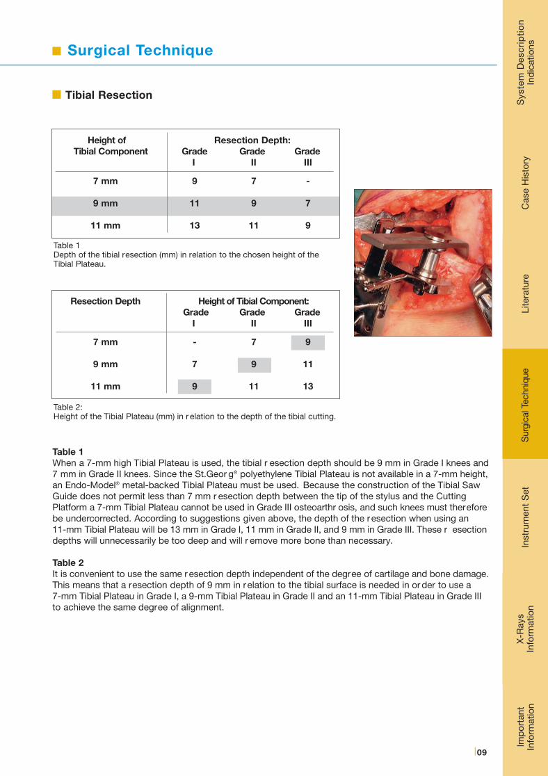
The St. Georg® Tibial Plateaus (polyethylene) are available in 3 heights (9, 11 and 13 mm) and the Endo-Model® (metal backed) in 4 heights (7, 9, 11 and 13 mm).
With the Femoral Trial Sled Prosthesis in place, a 9-mm Tibial Trial Plateau is positioned. This is easiestwhen the knee is flexed at least 90°. Some valgus load may be needed. If the Tibial Component has a tendency to tilt anteriorly, the posterior angle of slope is too small. This can be corrected with a rasp.
Extend the knee to test the stability. In a normal knee there should be only a few millimeters’ space betweenthe components under valgus stress in a neutral position. If the gap is too wide change to a higher TibialComponent. In genu recurvatum, the gap is wider in the neutral position a nd the knee is stable only inhyperextension. Try to obtain the same degree of hyperextension of the knee as was present preoperatively,otherwise there is a risk that the knee will be over corrected in valgus.
x_Link_MITUS_USA_Inhalt_10.08_NEU:. 15.05.2012 17:23 Uhr Seite 20
Surgical Technique
X-R
ays
Info
rmat
ion
Imp
orta
nt
Info
rmat
ion
Lite
ratu
reIn
stru
men
t S
etC
ase
His
tory
Sys
tem
Des
crip
tio
nIn
dic
atio
nsS
urgi
cal T
echn
ique
|19
Trial Reduction
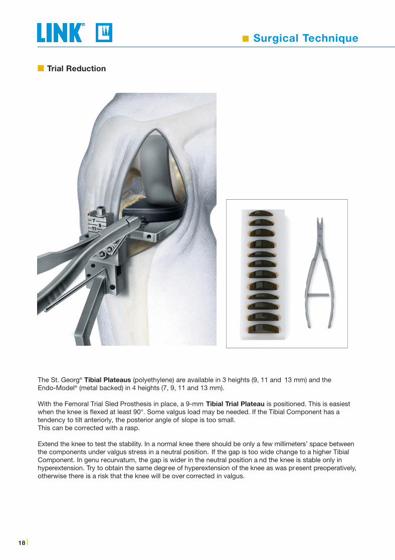
If the knee is too tight, remove the Tibial Trial Component and the Fixation Pin in the Cutting Platformand loosen Screw (A). Deepen the resection by lowering the platform to the appropriate level by turningScrew (B) using a Screwdriver. As a rule 1-mm increase in resection depth increases varus angulationby 2 degrees.
Secure the Cutting Platform by tightening Screw (A) and stabilize it with a Fixation Pin thr ough one ofthe unused holes in the Cutting Platform.
Perform the cut and repeat the trial by using the same height of the Tibial Trial Component.
A
B
x_Link_MITUS_USA_Inhalt_10.08_NEU:. 15.05.2012 17:23 Uhr Seite 21

Surgical Technique
20 |
Prepare the space for the keel of the Endo-Model ® Tibial Plateau (metal backed), place the head of theCancellous Bone Compressor into the recess of the tibial Template and impact it using the Impactor.
The keel of the St. Georg® Tibial Plateau (polyethylene) is larger. To prevent fractures of the tibial condyleremove some bone with a chisel before impacting the Bone Compressor.
Whichever Tibial Plateau is being used, the tibial surface needs to be pr otected during the compression ofthe bone with the tibial Template, which is laid on the saw ing platform. Test that the final choice of TibialPlateau fits and can be placed easily. Some valgus stress will be needed. The keel slot may be extendedanteriorly if necessary.
Cementation
x_Link_MITUS_USA_Inhalt_10.08_NEU:. 15.05.2012 17:23 Uhr Seite 22

Surgical Technique
X-R
ays
Info
rmat
ion
Imp
orta
nt
Info
rmat
ion
Lite
ratu
reIn
stru
men
t S
etC
ase
His
tory
Sys
tem
Des
crip
tio
nIn
dic
atio
nsS
urgi
cal T
echn
ique
|21
Before cementing the prosthesis remove the Tibial Saw Guide.
Prior to cementing inject 40 ml of 0.25 % Mar cain® (Bupivacain) into the capsule to minimize postoperativepain and to facilitate the mobilization of the patient. Using an appr opriate cementing technique, cementthe Femoral Prosthesis first. Remove excess cement with the cur ette.
Extend the knee to a neutral position and allow the cement to harden. Remove any remaining excesscement.
Release the tourniquet and carry out careful hemostasis. The capsule and skin are sutured with the kneeflexed at 90°.
Cementation
x_Link_MITUS_USA_Inhalt_10.08_NEU:. 15.05.2012 17:23 Uhr Seite 23

Instrument Set
22 |
MITUS® Instrument Set, completefor Minimally Invasive OP Technique of LINK® Unicondylar Sled Prosthesis Endo-Model®
Art.-Nr. / Item No.Instrument Set complete(Container 1 + 2)
15-2200
05-2001/03
05-2002/03
15-2200/02
15-2200/03
15-2200/01
Set complete in 2 Standard Containers N11 & N21, on 3 trays with product illustrations and storage inserts
N11 Standard Container, empty575 x 275 x 100 mm
N21 Standard Container, empty575 x 275 x 130 mm
Lower Tray (Container 1), emptyperforated stainless steel550 x 265 x 50 mm
Upper Tray (Container 1), emptyperforated stainless steel550 x 265 x 50 mm
Tray (Container 2), emptyperforated stainless steel550 x 265 x 50 mm
x_Link_MITUS_USA_Inhalt_10.08_NEU:. 15.05.2012 17:23 Uhr Seite 24

X-rays / Information
Imp
orta
nt
Info
rmat
ion
Lite
ratu
reC
ase
His
tory
Sys
tem
Des
crip
tio
nIn
dic
atio
nsS
urgi
cal T
echn
ique
|23
X-rays, 110% actual size, 1 sheet
15-2021/10 for Endo-Model® Sled Prostheses 15-2020/40 to 15-2020/60
15-2021/11 for Endo-Model® Tibial Plateaus (metal-backed)15-2030/01 to 15-2030/12
15-2021/12 for St. Georg® Tibial Plateaus (non metal-backed)15-2028/03 to 15-2028/12
Catalog MITUS® Implants & InstrumentsOrder Nr. 739 dt-en/Impl.
X-rays
Information
Available on request
Inst
rum
ent
Set
X-R
ays
Info
rmat
ion
CD MITUS® Surgical Technique
x_Link_MITUS_USA_Inhalt_10.08_NEU:. 15.05.2012 17:23 Uhr Seite 25

24 |
x_Link_MITUS_USA_Inhalt_10.08_NEU:. 15.05.2012 17:23 Uhr Seite 26

Important Information
Please note the following regarding the use of our implants:
1. Choosing the right implant is extremely important.The size and shape of the human bone determine the size and shape of the implant. Load capacity is therefore also limited. Implants are not designed to withstand unlimited physical str ess. Demands should not exceed normal functional loads.
2. Correct handling of the implant is exceedingly important.Altering the shape of a finished implant shortens its life span. Under no circumstances should the implant be bent sharply, snapped off, bent back, grooved or scratched. Our implants may not be combined with implants from other manufacturers.
The instruments indicated in the Surgical Technique must be used to ensure safe implantation of the components.
3. Implants must not be reused.Even if a used implant looks undamaged, it must be assumed that the material has become inter nally fatigued.
4. After-treatment is also very important.The patient must be informed of the limitations of the implant. The load capacity of an implant cannot compar e with that of healthy bone!
5. Unless otherwise indicated, implants are supplied in sterile packaging.Note the following conditions for storage of packaged implants:
• Avoid extreme or sudden changes in temperature.
• We recommend a storage temperature of 18–22°C at 50–65% humidity.
• Avoid direct sunlight.
• Protect implants from damp, moisture and mechanical damage.
• Implants may be stored in their original packaging for up to 5 years after the date of manufactur e.
The “Use by” date is indicated on the pr oduct label.
• Do not use an implant if the packaging is damaged.
6. Traceability is important.Please use the documentation stickers provided to ensure traceability.
7. Further information on the material composition is available on request from the manufacturer.
Follow the instructions for use!
WALDEMAR LINK GmbH & Co. KG, Hamburg.
All content in this catalogue, including text, pictur es and data, is copyright-protected. Every instance of use not permit-ted by the German Copyright Act is subject to our prior consent. In particular , this applies to the r eproduction, editing,translation, saving, processing or passing on of content stored in databases or other electronic media and systems. Theinformation in this catalogue is solely intended to describe the pr oducts and does not constitute a guarantee.
The Surgical Technique described has been written to the best of our knowledge and belief but it does not r elieve thesurgeon of his responsibility to duly consider the particularities of each individual case.
Unless otherwise indicated, all instruments are made of stainless steel.
x_Link_MITUS_USA_Inhalt_10.08_NEU:. 15.05.2012 17:23 Uhr Seite 27

WALDEMAR LINK GmbH & Co. KG
Barkhausenweg 10 · D-22339 Hamburg
P.O. Box 63 05 52 · D-22315 Hamburg
Phone: +49 (0)40 5 39 95-0 · Fax: + 49 (0)40 5 38 69 29
e-mail: [email protected] · Internet: www.linkhh.de
© W
. Li
nk 2
000
• 73
9 en
/OP
/10.
08
x_Link_MITUS_USA_Inhalt_10.08_NEU:. 15.05.2012 17:23 Uhr Seite 28