Mitsubishi FR-Z120
74
MITSUBISHU VVVF TRANSISTOR INVERTER - INSTRUCTION MANUAL - MITSUBISHI A ELECTRIC
-
Upload
tanun-niyomjit -
Category
Documents
-
view
401 -
download
24
description
Mitsubishi FR-Z120
Transcript of Mitsubishi FR-Z120
MITSUBISHU VVVF TRANSISTOR INVERTER
- INSTRUCTION MANUAL -
MITSUBISHI A ELECTRIC
I
3

HANDLING GUIDANCE Improper use and operation might cause unforseen trouble. read this manual carefully to operate inverter for a long tjme without trouble.
Before using your inverter, please
Molded cace *circuit breaker
(MCCB)
Magnetic contactor (MC)
Power supply
Do not apply voltage over the permissive voltage to the main circuit.
Refer to page 9-1.
DO NOT OPERATE THIS (MC) to start/stop the inverter and the motor.
I I inverter 43
MEGGER TEST Refer to page 7-1 and 7-2 when this insula- tion resistance test is performed.
I N STALLATI 0 N
Place the inverter in a clean and well-ventilated location. Do not install the inverter to direct sunlight, high temperature, etc.
0 Permissive ambient temperature
0 Location and space requirement for installation
: See page 9-1.
: See page 4-1.
SETTING OF CONTROL VARIABLES All control functions can be set by operating the PU “Parameter Unit“.
oHow to use the PU operation check 0 Function list 0 Mondtor and disDlav
: See page 11-1. : See page 6-1. : See page 19-1 and 19-2. : See Dane 16-1.
E Q U I PM ENT TO OUTPUT ‘wm 2 To the inverter output, DO NCT CONNECT the followings: 0 Power capacitor 0 Surge suppressor 0 Noise filter (model FR-BIF, option)
WIRING Note that miswiring not only causes damage to the inverter, but also endangers the operater.
o Main circuit ‘0 Control circuit Terminals for wiring OTerminal arrangement.
: See page 5-2. : See Page 5-2. : See page 9-4and 9-5. : See page 5-3.
3

M ITSU B ISH I TRANSISTOR I NVERTER FREQROL-2120 ,--.
Thank you for your purchase of Mitsubishi Transistor Inverter FREQROL-2120. This inverter is a variable-frequency power supply unit used to control a squirrel-cage induction motor.
IMPORTANT NOTE This instruction manual describes handling, installation, operation and maintenance of the inverter. Although it is easy to use the inverter, improper use and mis-operation might cause unforeseen trouble. Before operating the inverter, read this manual carefully. Your inverter is built to a high standard of quality and reliability. Correct application and regular inspection, should give you long, trouble free, operation.
-CONTENTS-
.INVERTER .............................................. $ 1, UNPACKING AND CHECKING.. 1-1
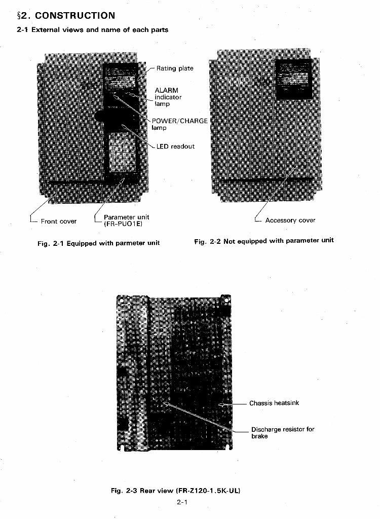
5 2. CONSTRUCTlON 2-1
$ 3. HANDLING lNSTRUCTlONS 3-1
$ 4, I N S T A L U T l O N 4- 1
_e r* $ 5 , WIRING 5- 1
$ 6 . OPERATION 6- 1
$ 7 , MAINTENANCE AND lNSPECTlON 7-1
$ 8 . TROUBLESHOOTlNG 8-1
$ 9, SPEClFlCATlONS 9-1
.............................................................. ..................................................
................................................................ ........................................................................
.................................................................. ..........................................
.......................................................... ............................................................
PARAMET ER UNIT
S11, I N S T A L U T l O N 11-1
$12. OUTLINE OF FUNCTIONS 12-1
$13. CONTROL DEVICES OF PARAMETER UNIT ................................ 13-1
514. OPERATION 14-1
$15. SElT lNGS OF CONTROL VARIABLES (PARAMETERS) - * . * * * * - * . * * * . - - * . * - 15-1
$16. MONITOR 16-1
517. DISPLAY 17-1
$18. FUNCTION NO, LIST 18-1
$19. DETAILS OF EACH FUNCTION 19-1
521. PARAMETER UNIT OUTSIDE DIMENSIONS, CABLE DETAILS . * * * . * - * * * * *
.............................................................. ..................................................
..................................................................
.................................................................... ......................................................................
f ........................................................ ..............................................
...................................... , $20. PARAMETER UNIT SPEClFlCATlONS 20-1
21 -1 I ,-m,.

IINVERTERI
0.5/0.4 Applicable
motor capacity (HP/KW)
91. UNPACKING AND CHECKING
After unpacking the inverter, check the following points.
(1) Check the rating plate on the front cover of inverter to make sure the model and output ratings meet your order
1/0.75 2/1.5 3/2.2 5/3.7
AM~TSUB~SHI I FR-2120-0.4K-UL 1 SOURSE I 3PH 200V50Hz200-230V60Hz I INVERTER POWER-
Without PU
I K J max 200-230V 0
' 2 Rated Output+ OUTPUT 1 current
FR-Zlzo-0.4K-UL FR-Z1zo-On75K-UL FR-ZQO-1 .SK-UL FR-Zlzo-2.2K-UL FR-Zlzo-3.7K-UL
I I TD840A671G51 1 MADE IN JAPAN
m MlTSUBlSHl ELECTRIC CORPORATION
Serial No.
-Type
Line voltage, frequency
Fig. 1-1 Rating plate
1 'With PU I FR-Zlzo-0.4KP-UL 1 FR-Zl20-0.75KP-UL I FR-2120-1 .SKP-UL I FR-2120-2.2KP-UL 1 FR-2120-3.7KP-UL 1
1-1
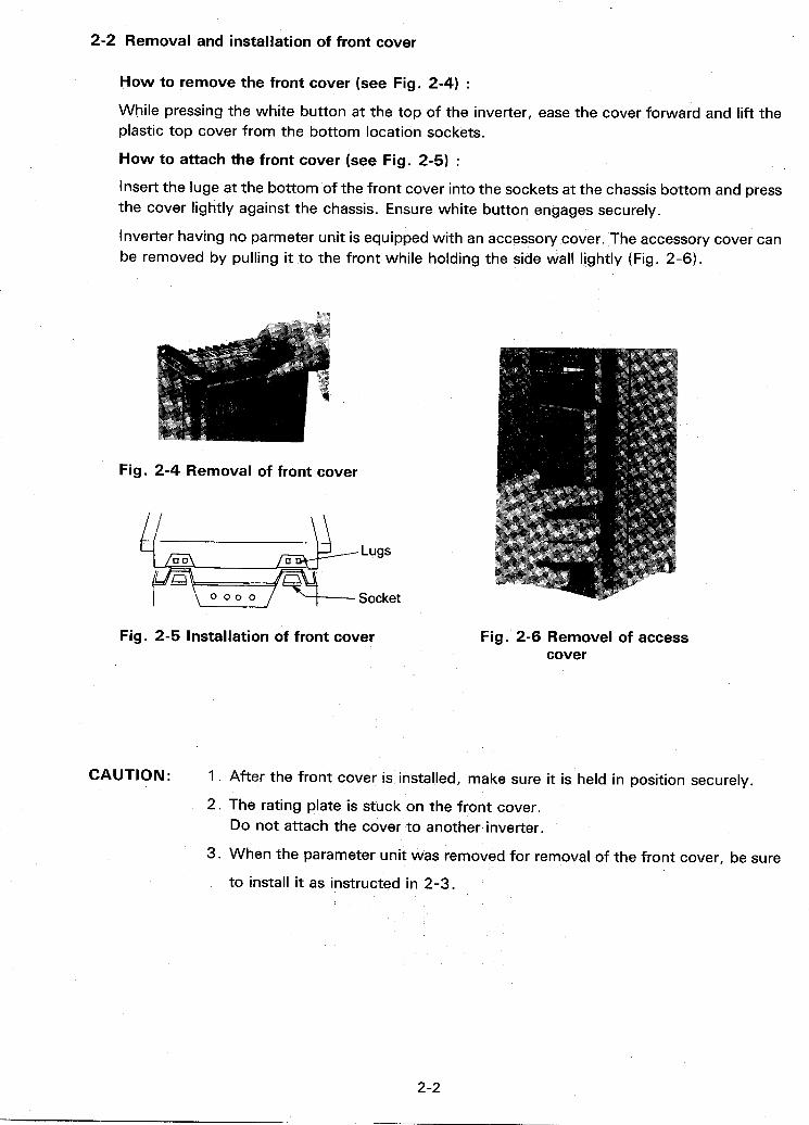
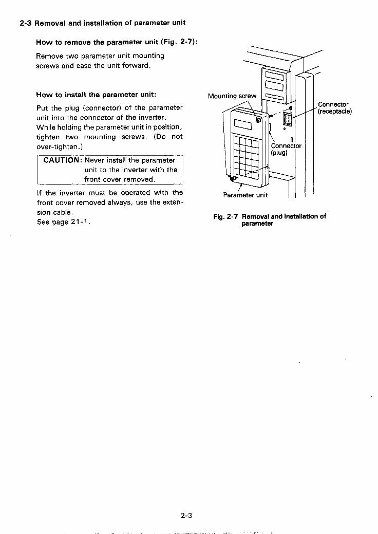
2-3 Removal and installation of parameter unit
How to remove the paramater unit (Fig. 2-71:
Remove two parameter unit mounting screws and ease the unit forward.
How to install the parameter unit:
Put the plug (connector) of the parameter unit into the connector of the inverter. While holding the parameter unit in position, tighten two mounting screws. (Do not over-tighten.)
CAUTION : Never install the parameter unit to the inverter with the front cover removed.
If .the inverter must be operated with the front cover removed always, use the exten- sion cable. See page 21-1.
' D 1
/ Parameter unit I 1 I
0
Connector ' (receptacle)
Fig. 2-7 Removal and installation of parameter
S3. HANDLING INSTRUCTIONS
If the inverter is handled improperly, normal operatdon cannot be performed or the inverter may be damaged.
Note the followings:
1 .
2.
3 .
4.
5.
6.
7.
8 .
Do not supply the over permissive voltage to the main circuit. (For power specifica- tions, refer to page 9-1)
Do not connect the input voltage (power supply) wirings to the output terminals (U, V, W), because it causes damage to the inverter.
The life time of the inverter greatly depends on ambient temperature. For the long life time, it is important to use at low temperature.
When the inverter is installed inside an enclosed box, pay attention to the box size and ventilation so that the inverter is operated at allowable temperature.
Do not operate the circuit breaker (MCCB) or magnetic contactom (MC) to start and stop the motor (inverter). Use the inverter start/stop signals (SFT, STR-SD).
To operate the inverter connected shortly to a large capacity power supply, surely use an AC reactor (power-factor correction reactor, model FR-BAL) to the inverter input side.
To the inverter output side, do not connect the power capacitor, surge suppressor,or noine filter (model FR-BIF, option).
To check insulation resistance with a megger, refer to page 7-2.
Do not perform overload operation over the inverter capabillity (d.g., repetition of thermal relay trip and reset).
3- 1
94. INSTALLATION
u Inverter
4-1 Handling during unpacking and installation
Carefully handle hte inverter when it is trasferred and installed. When the inverter is carried, do not hold it in such a manner that force is exerted on only the front panel.
fl,
0
0
/ /
4-2 Environment
(1) Place the inverter in a clean and well-ventilated location. Do not install the inverter in direct sunlight, high temperature, high humidity, dust, corrosive gases, or hazardous areas.
Install the inverter in a vibration free location. (2)
4-3 Mounting position and clearances
(1) Install the inverter securely and vertically with bolts or screws so that the letters "FREQROL-2120" face front.
(2) When the inverter is equipped with a parameter unit, install the inverter where the operator can touch it easily.
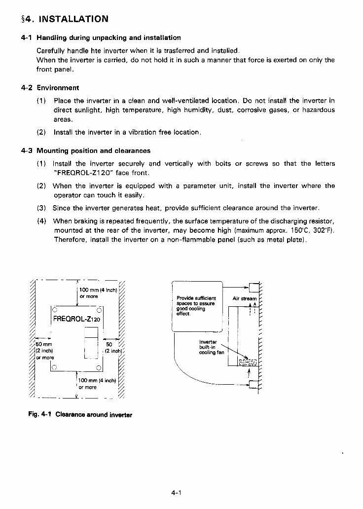
(3) Since the inverter generates heat, provide sufficient clearance around the inverter.
(4) When braking is repeated frequently, the sutface temperature of the discharging resistor, mounted a t the rear of the inverter, may become high (maximum approx. 15OC, 302°F). Therefore, install the inverter on a non-flammable panel (such as metal plate).
100 mm (4 inch)
Fig. 4-1 Clearance around inverter
m e 9 Provide sufficient 1 fl[ spaces to assure good cooling 1 effect.
I I 1 I L
, -
4- I
I I, I 'I ' ' .I.

CONS1 DERATDON FOR AMBl ENT TEMPERATURE
The life time of the inverter depends on the ambient temperature. The ambient temperature
FREQROOL rl _ _ - _ - - - - _ - _ - MwFr ing point X
should not exceed the permissive value. ~ o i ~ ~ ~ ~ 0, t--j 50 rnm (2 inch) Measure the ambient temperature a t the positions
shown in figure A.
Permissive ambient temperature: t 50°C (t 122°F)
50 m m f ' (* inch) -X Measuring point
Fig. A
4-4 Inverter housed in enclosure
When two or more inverters are housed in an enclosure or one or more inverter are housed in an enclosure equipped with a fan, locate each inverter and fan so that the maximum cooling efficiency can be achieved.
r---i !nn: Inverter Inverter
IHMI I Built-in ' I cooling fan I
(GOOD)
Two or more inverters housed in an enclosure
(GOOD) (WRONG)
Location of ventilating fan
4-2
$5. WIRING
CAUTIONS OF WIRING:
(1) Do not connect power supply to the output terminals (U, V, W), because such miswiring causes not only damage to the inverter, but also danger to the operator.
Be sure to use sleeved solderless terminals for the main circuit cable terminals.
Terminals P and PR are used to connect a discharging resistor for increased braking (option). Do not connect a brake unit (type BU) or other devices to these terminals.
The inverter cannot protect against accidents cue to leakage. Pay attention so that cables do not touch the chassis, etc. Be sure to ground the inverter with the ground terminal.
In case of not inserting magnetic contactor (MC) to the inverter primary side, if the power failure happens for a short time, the inverter restarts automatically a t the time of restoration of power, because STF or STR signal still remain.
If this automatic restart may give damage to human body or machine, re-supply the power with safety after being sure to shut off the power with MC.
If the commercial power changeover circuit is connected outside the inverter, check the phase sequence that the motor rating direction is the same in any operation.
Since the speed reference signals (terminals 2 and 5) are not isolated from the control circuit in the inverter, do not ground common terminal 5.
Do not short- circuit terminals across 10 (Supply for speed reference) and 5 (com- mon). Connection of these terminals will damage the inverter.
(2)
(3)
(4)
(5)
(6)
(7)
( 8 )
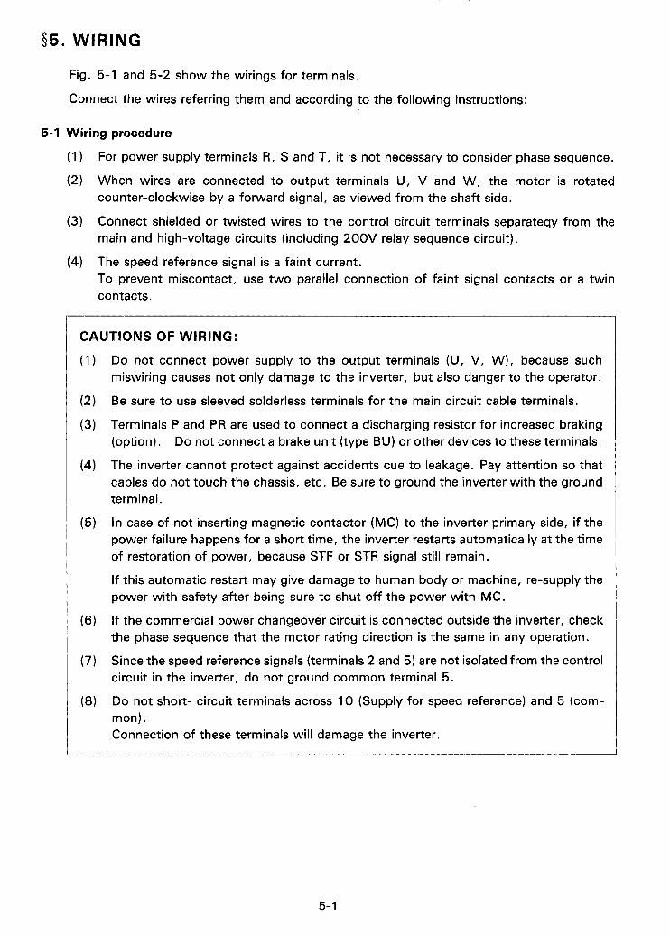
Fig. 5-1 and 5-2 show the wirings for terminals.
Connect the wires referring them and according to the following instructions:
1
5-1 Wiring procedure
(1 )
(2)
(3)
(4)
For power supply terminals R, S and T, it is not necessary to consider phase sequence.
When wires are connected to output terminals U, V and W, the motor is rotated counter-clockwise by a forward signal, as viewed from the shaft side.
Connect shielded or twisted wires to the control circuit terminals separateqy from the main and high-voltage circuits (including 200V relay sequence circuit).
The speed reference signal is a faint current. To prevent miscontact, use two parallel connection of faint signal contacts or a twin contacts

5-2 Wiring diagram
For terminal description, refer to page 9-4.
(1) Control circuit
Fig. 5-1
% Note: This resistor is not required when meter is calibrated on parameter unit. (Refer to page 18-7.)
(2) Main circuit
Power supply
FR-Z120-2.2K, 3.7K
Power supply
FR-Zl20-0.4Kto 1 .5 K Fig. 5-2
CAUTION : The built-in resistor for brake is connected to terminals P and PR. If opera- tion is in particularly heavy duty condition and requires a brake resistor having a larger capacity, disconnect the built-in resistor from these termi- nals and connect an exclusive external resistor to the terminals. /ca
5-2
, nm,
R S T U V W
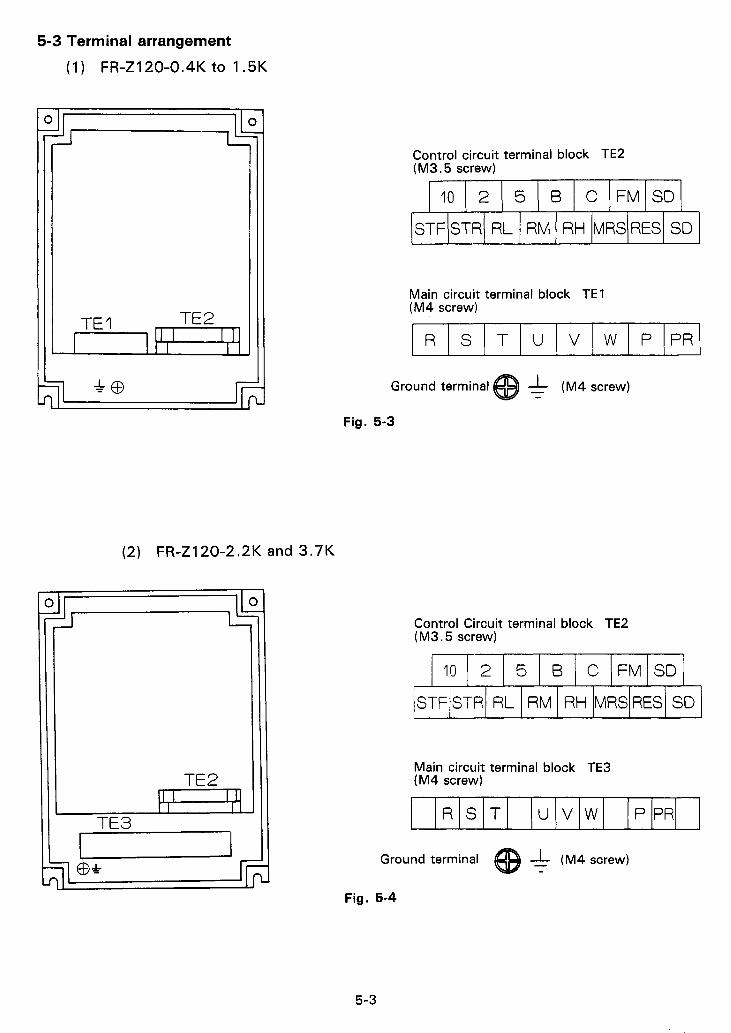
5-3 Terminal arrangement
(1) FR-Z120-0.4K to 1.5K
P P R
Control circuit terminal block TE2 (M3.5 screw)
1 IO 1 2 15 1 B I c I F M / S D ~
R S T
STF/STR/ RL 1 RM I RH IMRS~RES~ SD
u v w P PR
Ground terminal @ (M4 screw)
Fig. 5-3
(2) FR-Z120-2.2K and 3.7K
Control Circuit terminal block TE2 (M3.5 screw)
I t2 R
I I 1 I I
TE3 7
1 IO 1 2 15 1 B 1 c / F M / S D /
ISTFISTRI RL 1 RM 1 RH (MRS~RES~ SD 1
Main circuit terminal block TE3 (M4 screw)
Ground terminal 1 - (M4 screw) - Fig. 5-4
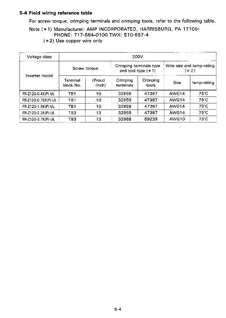
5-4 Field wiring reference table
For screw torque, crimping terminals and crimping tools, refer to the following table.
Note ( * 1) Manufacturer: AMP INCORPORATED, HARRISBURG, PA 17105- PHONE: 71 7-564-0100 TWX: 510-657-4
( * 2) Use copper wire only
Voltage class 200v
Crimping terminals type and tool type ( * 1) Screw torque
I Inverter model I I I I I I -I
Wire size and temp-rating ( * 2 )
Terminal block No.
Size temp-rating (Proud Crimping Crimping -Inch) terminals tools
1 FR-Z120-0.75K(P)-UL 1 TBI I 10 I 32959 I 47387 1 AWG14 1 75°C 1 FR-Z120-0.4K(P)-UL I TB 1
I FR-Z120-1.5K(P)-UL 1 TBI 1 10 I 32959 I 47387 I AWG14 1 75°C I
10 I 32959 1 47387 I AWG14 1 75°C
I FR-Z120-2.2K(P)-UL 1 TB3 1 13 1 32959 I 47387 I AWG14 1 75°C I I FR-Z120-3.7K(P)-UL I TB3 1 13 1 32968 I 59239 I AWG10 I 75°C I
5-4

56. OPERATION
1
6-1 Pre-operation checks i e
IMPORTANT
The inverter can be operated only on the para meter unit. * "Operation on parameter unit"
After the inverter has been installed and wired, check the following points before operation:
(1 ) Check that wiring is correct. Pay special attention to check that power supply cables are not connected to U, V and W.
(2) Check that there is no short-circuit due to wire offcuts, etc.
(3) Check that short-circuit and earth fault do not exist in the input and output circuits.
(4) Check that all screws, terminals and other fasteners are tight.
CAUTION FOR INSULATION RESISTANCE TEST WITH MEGGER
o For insulation resistance test with megger, refer to page 7-1.
o Never apply the test voltage to the control circuit terminals and across the inverter terminals.
Ill.,.,
6-2 Operation modes
The inverter can be operated in any one of the following three modes:
Mode
0
Operation mode (FUNCTION 79)
Selection can be made between "Operation with external signal" and "operation on para- meter unit" by operating the parameter unit (this mode is selected when the inverter is shipped).
Status after power is turned on (or reset)
"Operation with external signal" 1 The inverter can be operated only with
"Operation with external signal" 1 2 1 external signal.*
Note*: To use these modes, function No. 79 (operation mode) should be set on the parameter unit. (For details, refer to P. 12-1)
1 OPERATION WITH EXTERNAL SIGNALS I A separatelly installed speed reference potentiometer and start switches (FWDIREV) are used to control the inverter (motor). To start operation, only connection of the speed reference potentiometer and start switches to the terminals of the inverter is required. The acceleration/deceleration time and the electronic thermal relay are set, as shown on page 18-1, when the inverter is shipped.
6- 1
.,.. , , . . - , , ,./ I

These settings can be changed by means of operation with parameter unit shown below. When the parameter unit is used in this opera- tion mode,.
ospeed is displayed by the readout, MCCB Inverter n
osetting of various functions can be checked, Start switch
o in case of operation failure, the cause of the F~~~~~~~ ‘ ~ 1 i r ? failure can be identified, and reference I-__
I L J
Pot. \ o operation status (motor current, motor rotating direction, etc.) can be monitored. Fig. 6-1 Operation with external
signals
[ OPERATION WITH PARAMETER UNIT I Keys or switches of the parameter unit are pressed to control the inverter (motor).
To control the inverter by the parameter unit, press (pu_l key.
MCCB Inverter Motor
FR-ZIZO - 3
Fig. 6-2 Operation with parameter unit
6-2
6-3 Pre-operation settings and adjustments
The inverter itself does not have control devices such as select switches and potenti- meter (as with previous models of FREQROL). When the settings (acceleration/deceleration time, electronic thermal relay setting, etc.) must be changed, the parameter unit (FR-PUO1 E) is used.
(For the initial settings, refer to page 19-1).
For methods of changing parameter setting, refer to the description "PARAMETER UNIT". ( P . l 1-1-19-7)
Settings and Adjustments:
o Maximum output frequency setting (frequency a t 5V input)
For operation with external input signals
The intial setting is that the maximum output frequency is 60Hz when speed reference signal (across terminals 2 and 5)is 5V. If it is necessary to obtain output frequency higher than 60Hz, the maximum output frequency setting must be changed (refer to page 19-2).
For operation with parameter unit
Output frequence can be changed up to the maximum output frequency limit (set to 120Hz when the inverter is shipped). Set the maximum frequency limit of inverter to frequency less than that a t the maximum permissive speed of motor.
0 Acceleration/deceleration time The intinal setting for acceleration and deceleration is 5sec.
The acceleration/deceleration time is the time from start to the frequency a t 5V input. (For details, refer to page 19-3 .)
0 Electronic thermal relay setting This relay is set in terms of current. Set the relay in accordance with the rated current of the motor.
0 Frequency meter calibration If an analog frequency meter is connected to terminals FM and SD without using a calibration potentiometer, the frequency meter does not read correctly (the pointer of frequency meter may swing over the limit when frequency reference signal is maximum).
The requency meter can be calibrated in either one of thefollowing ways:
( 1 ) Connect a calibration potentiometer
(2) Use the parameter unit.
6-3
I b *

How to calibrate the frequency meter using the parameter unit
( 1 ) Set the same output frequency as frequency a t 5V input signa1,operating keys of the parameter unit.
- 6OHz is set for output frequency
(2) Press /FWD1 or /REV1 t o start the motor.
(3) Enter ~ 1 ~ ~ 1 0 ( / 1 1 . (4) Press or key t o calibrate the frequency meter.
(5) After the frequency meter has been calibrated, press key.
(6) Press key t o stop the motor.
6-4 In-operation settings and adjustments
After checking that the inverter signal is off, turn on the circuit breaker (MCCB) and magnetic contactor (MC) in the inverter input circuit.
Then operate the inverter and check the operation.
6-4

,-5*
(Turn on the power) ** * * * - The power lamp on the inverter I front panel turns on.
I
When the parameter Refer to description 1 unit is used ... 1 about [PARAMETER UNIT] (P.l l-1-19-7) ,
The inverter automaically becomes ready for operation with external signals when the power is turned on.
Turn on forward or reverse start signal (or switch).
a Slowly turn the speed reference pot. Clockwise until stops. (Motor now at full speed.)
Slowly turn the speed reference pot. Counterclockwise to "zero". (Motor now stopped. )
Press @ key to make operative the parameter unit.
0 For direct setting
Enter the desired output frequency by operating numerical keys of the parameter unit and then press [WRITE] key.
o For analog setting
Press @ key to increase frequency displayed by the readout to the desired output frequency and then press [m] key.
45
Press [m] or IREV] key
Press [m] key
Note 1 .
Note 2.
6-5

Note 1 : As the frequency displayed by the readout of parameter unit increases, the motor speed increases.
Note 2: As the frequency displayed by the readout of parameter unit decreases, the motor speed decreases. When the output frequence is reached to the starting frequency, the DC dynamic brake is activated and the motor is brought to sudden stop.
Check points:
(1 ) Check that the motor rotates in correct direction. (For relationship between motor phase sequence and direction of rotation, refer to chapter §5. WIRING.)
(2) Check that the motor does not generate unusual hums or vibration.
(3) Check that change of output frequency is displayed correctly.
(4) Check if "ALARM" lamp lights during acceleration or deceleration (inverter trip).
If it lights, perform the following check:
o Check if load is too heavy. o Reduce boost amount. o Increase acceleration/deceleration time.
CAUTION :
(1 ) If the forward (STF) and reverse (STR) start signals turn on at the same time, the inverter will not start. If these signals turn on simultaneously during operation, the inverter is decelerated to a stop.
During deceleration, the DC dynamic brake is actuated at less than 3Hz (less than the starting frequency if speed reference signal is gradually reduced) for 0.5 seconds. During this period, the motor may generate a high-pitched hum, but this is not a failure, nor a sign of trouble. This is normal during DC braking.
If "ALARM" lamp lights and the motor stops after coasting, check that the motor has completely stopped and then shut off the power or reset the inverter using the reset terminal.
(2)
(3)
a,
6-6

Q 7 . MAINTENANCE AND INSPECTION The inverter is a piece of static equipment consisting mainly of semiconductor elements. To prevent troubles occurring due to high temperature, humidity, dust, intense vibration, component deterioration, etc., it is necessary to execute periodic inspection.
7-1 Caution for maintenance and inspection
(1) The operator must check whether power supply is ON or OFF by himself to prevent m isope rat ion by others.
(2) After the power is switched off, the capacitor remains charged a t high voltage for a while. Before making an inspection, check that the CHARGE lamp (used also as the POWER lamp) in the display panel is off and voltage across inverter main circuit terminals P and N is below 30 DC with a multimeter, etc.
7-2 Inspection points
This inverter is equipped with power and error indicator LED (located in the display panel). It is advisable that you recognize LED definitions. Note the normal settings of the electronic thermal relay, acceleration/deceleration time, etc.
( 1 ) Daily inspection During operation, check the following:
(a) The motor operates properly.
(b) The environment is normal.
(c) The cooling system is normal.
(d) There is no unusual vibration and moise.
(e) There is no overheat and discoloration in any component.
During operation, check inverter input/output voltage with a multimeter
(2) Periodic inspection Check the following periodically with the inverter stopped:
(a) Check that the cooling system is in good condition. Clean air filters, etc.
(b) Screws, bolts, nuts and other fasteners may become loose with time due to vibra- tion, thermal expansion/retraction, etc. Retighten loose screws or other fasteners.
(c) Check if conductors and insulators are not corroded or damaged.
(d) Measure insulation resistance.
(e) Check the cooling fan, smoothing capacitor, contactor and realy.
Table 7-1 shows the standard daily and periodic inspection schedule.
(3) Insulation resistance test with megger
(a) Before checking insulation resistance of the external circuit with a megger, discon- nect wires from all inverter terminals so that test voltage is not applied to the inverter circuits.
7-1

(b) Conduct the insulation resistance test on the inverter main circuit only, as shown in Fig. 7-1. DO NOT conduct the test on the control circuits.
(c) To check the control circuits for continuity, use a multimeter (high resistance range). DO NOT USE A MEGGER OR BUZZER TO CHECK.
Remove these short-circuit wires after the test has been completed.
U Inverter R - - - - - -
Ground terminal
Fig. 7-1 Insulation resistance test with megger
7-2

0
3
0 00
0 000
30
0
0
0
0
oc
00
7-3

7-3 Measuring instrument selection and usage
To observe the insulation resistance, voltage, current, signal level, waveform, etc., use the measuring instruments described below.
(1 ) Main circuit measurements
There are input/output voltages and currents measurements, load (motor) continuity check, insulation check, voltage and current waveform observations.
The following are the particularly important items to be checked with the following instruments:
0 Multimeter
For continuity check with a multimeter, be careful of sneak path circuit. DO NOT make continuity check for the inverter circuit transistor module with the motor connected, and for the converter circuit diode module with the power connected. Make continuity check for only components to be checked and remove the wirings to other components.
@ Voltmeter and ammeter
The input (power supply) voltage is sine-wave of the commercial frequency. To measure the input voltage, any appropriate instrument may be used. The input and output current waveforms include many high harmonic components. To measure the input and output currents, use a moving-iron type ammeter as it indicates value in r.m.s. To measure the output voltage, use a rectifier type voltmeter because it reads nearly the basic wave component of the voltage waveform which is used as the reference value of torque generated by the motor.
Anyhow, it is important to note the types of used instruments as well as normal value of measurements and always use the same instruments at inspection.
/"*\
0 Osci I Isscope
To measure high voltage (main circuit), insulate the power supply of oscilloscope and use a high-voltage probe or insulate the measured point with a potential transformer or current transformer. In the latter case, the potential transformer or current transformer should have sufficient capacity to prevent magnetic saturation.
(2) Control circuit measurements
There are speed refernce signal and inverter control voltage measurements and waveform observation.
Note the following:
@ Voltage measurement and waveform observation
Since the flowing currents of these signals are faint and the circuit impedances are high, use an instrument, input resistance of which is as high as possible (100 kohm to 1 megohm). It is recommended to measure using a digital multimeter and oscilloscope. Since input resistance of multimeter set in low range is significantly low, value read by multimeter may show lower than the true value. Therefore, pay attention to it.
-3
7 -4

0 Common tine connection
Measurings point
~ a i n 1 2:;;' circuit Instruments
Connect the instrument common line to the optimum point of circuit, i.e. nearest common point to the measuring point.
@ Instrument characteristics
For waveform observation, use an oscilloscope wich has characteristics meeting the waveform to be measured. For example, the inverter base drive waveform can be observed with a 10 MHz osciloscope. To measure transient waveform at rise of signal (dv/dt or di/dt), however, oscilloscope of 200 MHz or larger frequency is required.
Measuring Item
in:::- I dz~;tv I Voltage Current I form Wave- Description
Table 7-2 Instruments and points to be measured
Voltmeter
Ammeter
Measure line and inverter output volt- age. Use a rectifier type. Measure line and output current. Use a moving-iron t w e .
0 0
0 0
Measure across batch of main circuit terminals and ground. (This does not apply to control circuit.)
t i Digital multimeter
Judges whether semiconductor ele- ! ment is proper or not. Used to know I conductivitv or resistfnce value.
1 Multimeter 0 1 0 1 I 0 1 0 I I
Used to measure circuit voltage instead of multimeter. 0 0 0
Used to observe waveform and mea- I ' 1 ' 1 ' l sure transient voltaae and current. I Oscilloscope 1 o 1 0 I
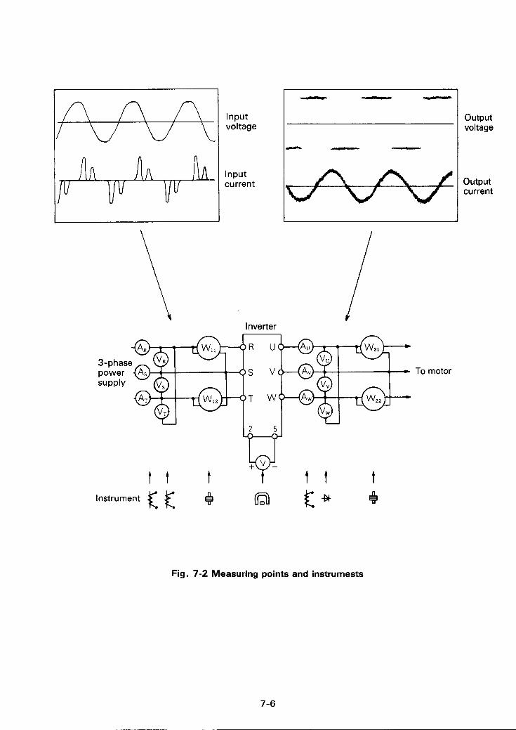
7-4 Method of measuing main circuit voltage, current and power
( 1 ) Voltage and current measurements
Since the inverter input/output voltage and current include high harmonic components, data (measurement results) depend on the instruments and circuits used in measurement.
To measure voltage and current with an instrument for commercial frequency application, use the instrument selected from Table 7-3, and the circuit in Fig. 7-2.
7-5
I
A A
input voltage
Input current
t f t Instrument Q
t f3
t t t 4
To motor
output voltage
output current
Fig. 7-2 Measuring points and instrumests
7-6

,
Table 7-3 Measuring points and measuring instruments
Item Measuring Point 1 Instrument 1 Remarks (Criterion)
Line voltage VI
Across R and S, S and T, fnd T and R
Moving-iron type Commercial voltage 0 For 200V class
50Hz 180-220V 60Hz 180-253V
Input current 11
R, S, and T line cur- Moving-iron type rents
Input power PI
At R, S and T, and across R and S, and S and T
E# Electrodynamic type
P1 =w11 +WlZ
Input power factor Pfl
To be calculated from the equation shown below, after line voltage, input current and input power are measured.
x 100% PI a v , * Il Pf, =
Output voltage V,
Across U and V, V and W,and W and U
Rectifier type (Moving-iron type is not acceptable)
Difference between phases is 5 1% or less of maximum output voltage.
Output current 12
U, V and W line cur- rents
Moving-iron type Current should be equal to or less than inverter rated current. Difference between phasses is 10% or less.
Output power PZ
On U, V and W, and across U and V, and V and W
# Electrodynamic type
P, = WZl + wzz
Output power factor Pf,
To be calculated from the equation shown below.
x 100% P2 nv,*1, Pf, =
Converter output Across P and N Q Moving coil type (Such as mul- timeter)
POWER lamp should light, 1.35xV1 Maximum voltage during regenerative braking:375& 15V
(To be continued)
7-7
. / " I I , "II ' ' ."''
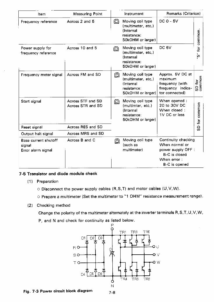
Item
Frequency reference
Power supply for frequency reference
Frequency meter signal
Start signal
Reset signal
Output halt signal
Base current shutoff signal Error alarm signal
Measuring Point ~
Across 2 and 5
Across 10 and 5
Across FM and SD
Across STF and SD Across STR and SD
Across RES and SD
Across MRS and SD
Across B and C
Instrument
a Moving coil type (multimeter, etc,) (Internal resistance: 50kOHM or larger)
a Moving coil type (multimeter, etc,) (Internal resistance: 50kOHM or larger)
a Moving coil type (multimeter, etc, ) (Internal resistance: 50kOHM or larger)
a Moving coil type (rnultimter, etc,) (Internal resistance: 50kOHM or larger)
a Moving coil type (such as multimeter)
Remarks (Criterion)
DC 0 - 5V
DC 5V
Approx. 5V DC a t maximum frequency (with frequency indica- tor connected)
When opened : 20 to 30V DC When closed : 1V DC or less
Continuity checking When normal or power supply OFF :
B-C is closed When error :
B-C is opened
-
C 0 E E 8 5 rc
u3
7-5 Transistor and diode module check
(1 ) Preparation
0 Disconnect the power supply cables (R,S,T) and motor cables (U,V,W).
o Prepare a multimeter (Set the multimeter to "1 OHM" resistance measurement range)
(2) Checking method
Change the polarity of the multimeter alternately a t the inverter terminals R,S,T,U,V,W,
P, and N and check for continuity as listed below. P
? TRI TR3 TR5
U
V
W
Fig. 7-3 Power circuit
A TR4 TR6 TR2
N
7-8 block diagram
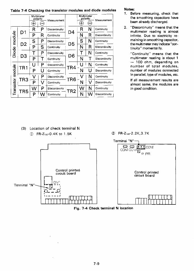
Table 7-4 Checking the transistor modules and diode modules
polarity
0 0 Measurement
u p Discontinuity
p U Continuity T R I
0 0 I Multimeter 1
W N Continuity T R 2 -1 N w Discontinuity
(3) Location of check terminal N 0 FR-Zi20-0.4K to 1.5K
Control printed circuit board
Term i n a I " N "
, , I /
Notes: 1. Before measuring, check that
the smoothing capacitors have been already discharged.
2. "Discontinuity" means that the multimeter reading is almost infinite. Due to electricity re- maining in smoothing capacitor, the multimeter may indicate "con- t inuity" momentarily. "Continuity" means that the multimeter reading is about 1 - 100 ohm, depending on number of total modules, number of modules connected in parallel, type of modules, etc. If all measurement results are almost same, the modules are in good condition.
@ FR-Zi20-2.2 K, 3.7 K
Terminal " N " 7
PR
Control printed circuit board
Fig. 7-4 Check terminal N location
7-9
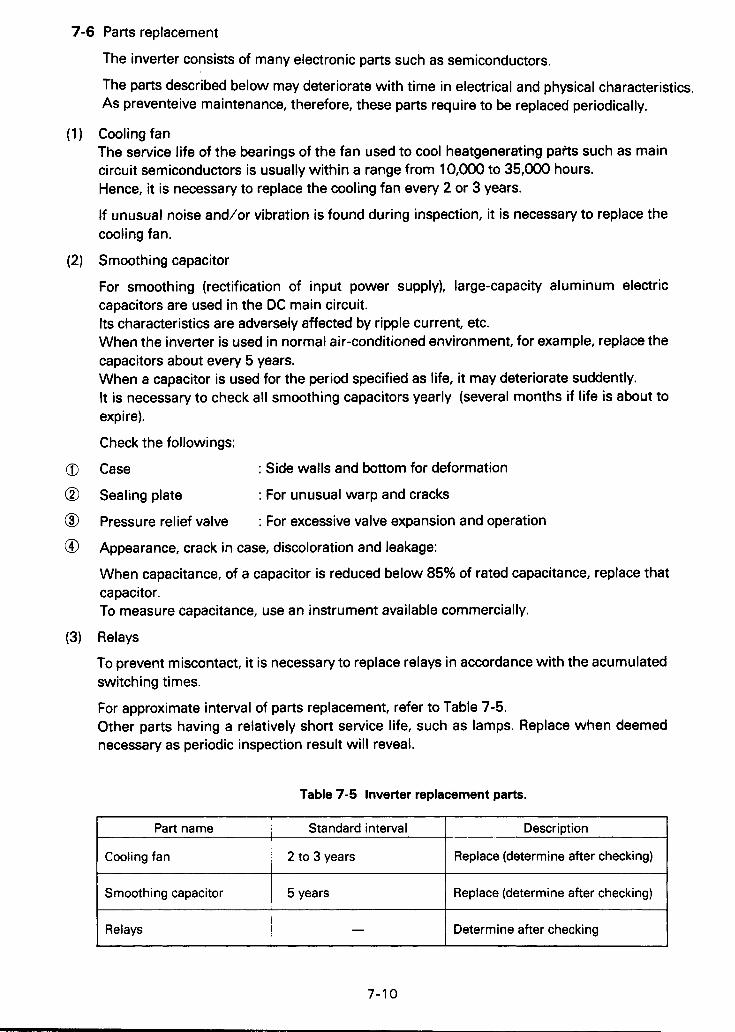
7-6 Parts replacement
Part name Standard interval
Cooling fan
Smoothing capacitor 5 years
2 to 3 years
The inverter consists of many electronic parts such as semiconductors.
The parts described below may deteriorate with time in electrical and physical characteristics. As preventeive maintenance, therefore, these parts require to be replaced periodically.
Cooling fan The service life of the bearings of the fan used to cool heatgenerating paits such as main circuit semiconductors is usually within a range from 10,000 to 35,000 hours. Hence, it is necessary to replace the cooling fan every 2 or 3 years.
If unusual noise and/or vibration is found during inspection, it is necessary to replace the cooling fan.
Smoothing capacitor
For smoothing (rectification of input power supply), large-capacity aluminum electric capacitors are used in the DC main circuit. Its characteristics are adversely affected by ripple current, etc. When the inverter is used in normal air-conditioned environment, for example, replace the capacitors about every 5 years. When a capacitor is used for the period specified as life, it may deteriorate suddently. It is necessary to check all smoothing capacitors yearly (several months if life is about to expi re).
Check the followings:
Case
Sealing plate
Pressure relief valve
Appearance, crack in case, discoloration and leakage:
When capacitance, of a capacitor is reduced below 85% of rated capacitance, replace that capacitor. To measure capacitance, use an instrument available commercially.
Relays
To prevent miscontact, it is necessary to replace relays in accordance with the acumulated switching times.
For approximate interval of parts replacement, refer to Table 7-5. Other parts having a relatively short service life, such as lamps. Replace when deemed necessary as periodic inspection result will reveal.
: Side walls and bottom for deformation
: For unusual warp and cracks
: For excessive valve expansion and operation
Description
Replace (determine after checking)
Replace (determine after checking)
I Relays - 1 Determine after checking I ~
7-1 0
58, TROUBLESHOOTING If a fault occurs and the inverter does not work properly, determine the cause referring to the following troubleshooting list and apply the remedy.
If the cause cannot be determined in accordance with the list, the inverter or its parts(s) is likely to be defective. For remedy of serious trouble or any inquiry, contact the nearest service representative.
8-1 Troubleshooting
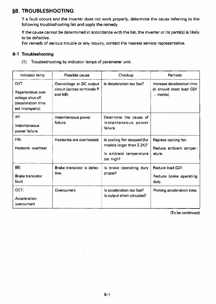
(1) Troubleshooting by indicator lamps of parameter unit.
Indicator lamp
OVT:
Regenerative over voltage shut off (deceleration time set improperly)
IPF:
Instantaneous power failure
FIN:
Heatsink overheat
BE:
Brake transistor fault
oc1:
Acceleration overcurrent
Possible cause
Overvoltage in DC output circuit (across terminals P and NB)
Instantaneous power failure
Heatsinks are overheated.
Brake transistor is defec- tive.
Overcurrent
Checkup
Is deceleration too fast?
Determine the cause of instantaneous power failure.
Is cooling fan stopped (for models larger than 2.2K)?
Is ambient temperature too high?
Is brake operating duty proper?
Is acceleration too fast? Is output short-circuited?
Increase deceleration time (it should meet load GD2 ... inertia).
Replace cooling fan.
Reduce ambient temper- ature.
Reduce load GD2.
Reduce brake operating duty.
Prolong acceleration time.
(To be continued)

Indicator lamp 1 Possible cause I Checkup
0 LT:
Stall prevention
oc2:
Long-lasting action of stall preventive function
Is motor overloaded?
Steady speed overcu rren t
OC3:
Deceleration overcurrent
Overcurrrent 1 Is load changed suddenly?
Is output short-circuited?
Is deceleration too fast?
Is output short-circuited?
THM:
Overload alarm
Motor thermal relay Is motor overloaded?
THT:
Overload alarm
Inverter thermal relay
Remedy
Eliminate sudden load change.
Prolong deceleration time.
Lighten load.
Change motor/inverter capacity.
Lighten load.
Change motor/inverter capacity.
* If an indicator lamp lights, the motor stops after casting. To resume motor operation, remove the cause, reset the protective function and restart the inverter.
8-2
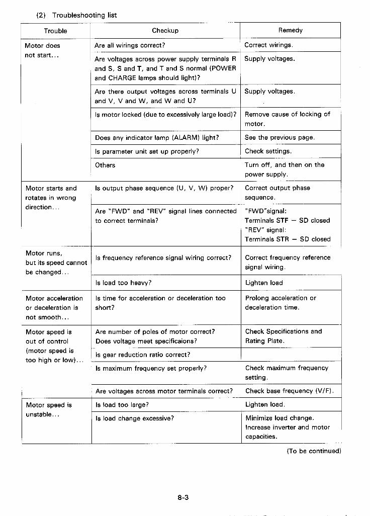
(2) Troubleshooting list
Remedy Trouble Checkup
Motor does l o t start.. .
Are all wirings correct? Correct wirings.
Supply voltages. Are voltages across power supply terminals R and S , S and T, and T and S normal (POWER and CHARGE lamps should light)?
Supply voltages. Are there output voltages across terminals U and V, V and W, and W and U?
Is motor locked (due to excessively large load)? Remove cause of locking of motor.
Does any indicator lamp (ALARM) light? See the previous page.
Check settings. Is parameter unit set up properly?
Others Turn off, and then on the power supply.
Motor starts and rotates in wrong direction. . .
Is output phase sequence (U, V, W) proper? Correct output phase sequence .
Are "FWD" and "REV" signal lines connected to correct terminals?
" F W D "sig n a I : Terminals STF - SD closed "REV" signal: Terminals STR - SD closed
Motor runs, but its speed cannot be changed.. .
Is frequency reference signal wiring correct? Correct frequency reference signal wiring.
Is load too heavy? Lighten load
Motor acceleration or deceleration is not smooth.. .
Is time for acceleration or deceleration too short?
Prolong acceleration or deceleration time.
Motor speed is out of control (motor speed is too high or low). . .
Are number of poles of motor correct? Does voltage meet specificaions?
Check Specifications and Rating Plate.
Is gear reduction ratio correct?
Is maximum frequency set properly? Check maximum frequency setting.
Check base frequency (VIF). Are voltages across motor terminals correct?
Is load too large? ~~~
Lighten load Motor speed is unstable.. . Is load change excessive? Minimize load change.
Increase inverter and motor capacities.
(To be continued)
8-3
, , " . , . I/ . , ( . ..,, *

Q 9.SPECIFICATIONS
9.1 Standard specifcations
0.5/0.4
1 .I
1/0.75 2/1.5 3/2.2 5/3 * 7
1.9 3.1 4.2 6.5
3 5 8 11 17
Model FR-Z120- 1 FR-Z120- 1 FR-Z120- 1 FR-Z120- I FR-Z120- 0.4K-UL 0.75K-UL 1.5K-UL 2.2K-UL 3.7K-UL
Applicable motor capacity (H P/kW)
Nominal output (kVA)
Output current
Maximum output voltage
(A)
($1)
Voltage and frequency Three-phase ,200VAC/ 50Hz, or 200/220/230/ 60Hz
Permissive voltage regulation
180 to 220V(220V+ 10%)/50Hz, 180 to 253V(200V- 10%,230V+ 10%)/60Hz
Permissive frequency regulation 2 5 %
Power supply capacity (kVA) ($2)
1.5 1 2 .5 1 4.5 5.5 1 9 ~~
Control method ~~
Sinusoidal wave PWM control system
Output frequency range 0.5-360Hz
Starting frequency 0.5- 1 OHz adjustable
Frequency resolution 0.01 Hz(less than IOOHz), or 0.1 Hz(more than 1 OOHz)-digital setting, or 1 /I 000 of maximum frequency-analog setting
Frequency accuracy Max. 0.01 % of preset output frequency-digital setting Max. k0.5% of maximum output frequency (at 25"C+ 1 OoC,77"F+ 18'F)--analog setting.
Base frequency selectable within 50-360Hz Constant torque or reduced torque pattern is selectable.
With manual torque boost
Voltage/frequency characteristic
Torque boost
Min. 1 50% (short t i me)
Min. 100% (short time)
Braking torque Regenerative
1 DC dynamic Actuated at less than 3Hz
Overcurrent withstand capability 150% for 1 minute,200% for 0.5 seconds
(To be continued)
9-1
~~
FR-2120- 0.4K-UL
~ ~ ~ ~~ ~~~
FR-2120- 1 FR-2120- ~ FR-2120- 7 FR-Z120- 0.75K-UL 1.5K-UL 2.2K-UL 3.7K-UL
S .O
.O
n _" 5
+ m - Y- o a
m
Max./Min .frequency limit setting
start signal
Accelertion/deceleration time
self cooling
3.1/6.8 I 3.317.3 I 4.o/a.a Fan cooling
6.3/14 I 6.4114
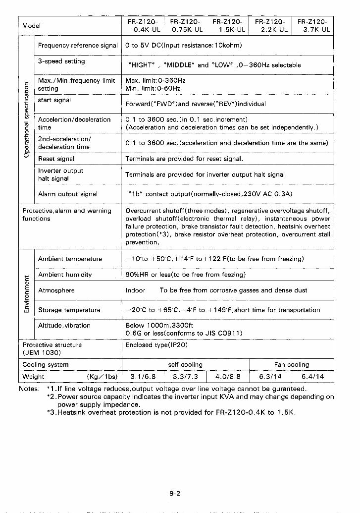
Model
0 to 5V DC(lnput resistance: 1 Okohm) Frequency reference signal
~ 3-speed setting "HIGHT" , "MIDDLE" and "LOW" ,0-360Hz selectable
Max. limit:0-360Hz Min. limit:0-60Hz
Forward ("FWD*) and reverse ("R EV") individual
0.1 to 3600 sec. (in 0 .1 sec,increment) (Acceleration and deceleration times can be set independently. )
V I .- 0. I to 3600 sec.(acceleration and deceleration time are the same) 2nd-acceleration1
Inverter output halt signal
Terminals are provided for reset signal.
Terminals are provided for inverter output halt signal.
Alarm output signal "1 b" contact output(normally-closed, 230V AC 0.3A)
Protective,alarm and warning functions
Overcurrent shutoff (three modes), regenerative overvoltage shutoff, overload shutoff(e1ectronic thermal relay), instantaneous power failure protection, brake transistor fault detection, heatsink overheat protection(*3), brake resistor overheat protection, overcurrent stall prevention,
- 1O"to + 50"C, + 14°F to+ 122"F(to be free from freezing) Ambient temperature
Ambient humidity 90%HR or less(to be free from feezing)
Atmosphere Indoor To be free from corrosive gasses and dense dust
Storage temperature -20°C to +65'C, -4°F to + 149"F,short time for transportation
Altitude, vibration Below 1000m,3300ft 0.6G or less(conforms to JIS CO91 1)
Enclosed type( IP20) Protective structure (JEM 1030)
Cooling system
Weight (Kg/ 1 bs)
Notes: * 1 .If line voltage reduces,output voltage over line voltage cannot be guranteed. *2. Power source capacity indicates the inverter input KVA and may change depending on
*3.Heatsink overheat protection is not provided for FR-Z120-0.4K to 1.5K. power supply impedance.
9-2

9-3 Block diagram
Parameter unit
(2nd Output a c c e l . / k t halt b.
decel. time)
Freauencv meter ,
I
*1 F-l Heatsink overheat
Cal ibrationlesistor 10
&C" 1 Frequency --Pl reference pot. I
I
CPU
A Y
LSI (Custom- made)
q I I
I 1
I
- - - --
* 1 : Heatsink overheat protection is not provided for FR-2120-0.4K to 1.5K. Fig. 9-1
9-3
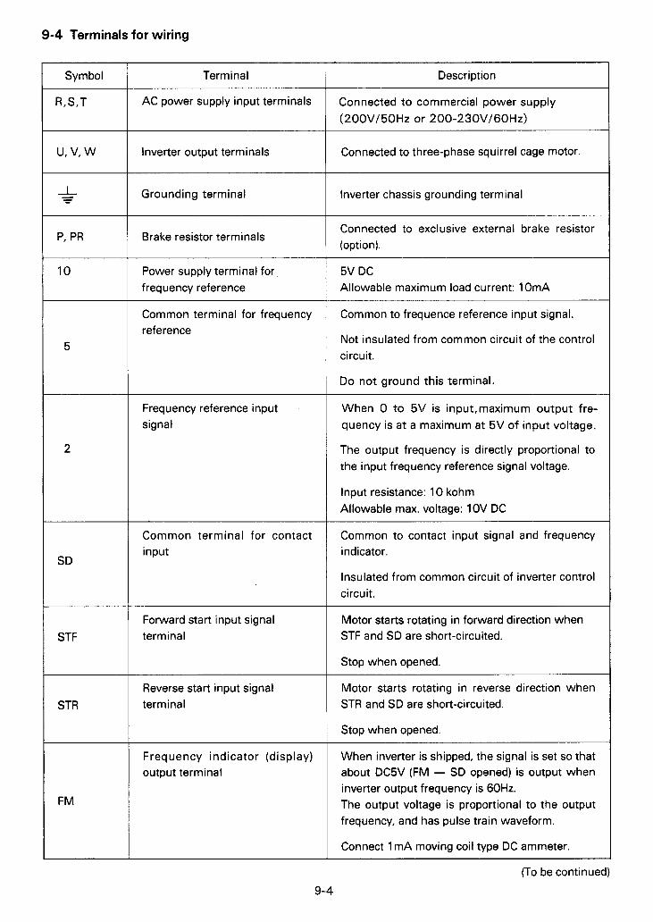
9-4 Terminals for wiring
Symbol
R,S,T
P, PR
10
5
2
SD
STF
STR
FM
Term i n a I
AC power supply input terminals
Inverter output terminals
Grounding terminal
Brake resistor terminals
Power supply terminal for frequency reference
Common terminal for frequency reference
Frequency reference input signal
Common terminal for contact input
Forward start input signal terminal
Reverse start input signal terminal
Frequency indicator (display) output terminal
Description
Connected to commercial power supply (200VI50Hz or 200-230V/60Hz)
Connected to three-phase squirrel cage motor.
Inverter chassis grounding terminal
Connected to exclusive external brake resistor (option).
5V DC Allowable maximum load current: 10mA
Common to frequence reference input signal.
Not insulated from common circuit of the control circuit.
Do not ground this terminal.
When 0 to 5V is input,maximum output fre- quency is a t a maximum a t 5V of input voltage.
The output frequency is directly proportional to the input frequency reference signal voltage.
Input resistance: 10 kohm Allowable max. voltage: 1 OV DC
Common to contact input signal and frequency indicator.
Insulated from common circuit of inverter control circuit.
Motor starts rotating in forward direction when STF and SD are short-circuited.
Stop when opened.
Motor starts rotating in reverse direction when STR and SD are short-circuited.
Stop when opened
When inverter is shipped, the signal is set so that about DC5V (FM - SD opened) is output when inverter output frequency is 60Hz. The output voltage is proportional to the output frequency, and has pulse train waveform.
Connect 1 mA moving coil type DC ammeter.
9-4
(To be continued)
- ' ' .'"l
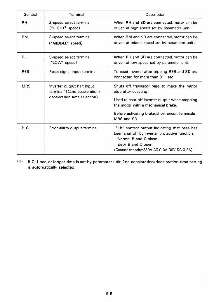
Symbol
RH
RM
RL
RES
MRS
B,C
Terminal
3-speed select terminal (“HI G HT* speed)
3-speed select terminal (*MIDDLE” speed)
3-speed select terminal (“LOW” speed)
Reset signal input terminal
Inverter output halt input terminal* 1 (2nd acceleration/ deceleration time selection)
Error alarm output terminal
Description
When RH and SD are connected,motor can be driven a t high speed set by parameter unit.
When RM and SD are connected,motor can be driven a t middle speed set by parameter unit.
When RH and SD are connected,motor can be driven a t low speed set by parameter unit.
To reset inverter after tripping,RES and SD are connected for more than 0.1 sec.
Shuts off transistor base to make the motor stop after coasting.
Used to shut off inverter output when stopping the motor with a mechanical brake.
Before activating brake,short circuit terminals MRS and SD.
“1 b” contact output indicating that base has been shut off by inverter protective function.
Normal:B and C blose Error:B and C open
(Contact capacity:230V AC 0.3A,30V DC 0.3A)
*1 : If 0.1 sec.or longer time is set by parameter unit,2nd acceleration/deceleration time setting is automatically selected.
9-5
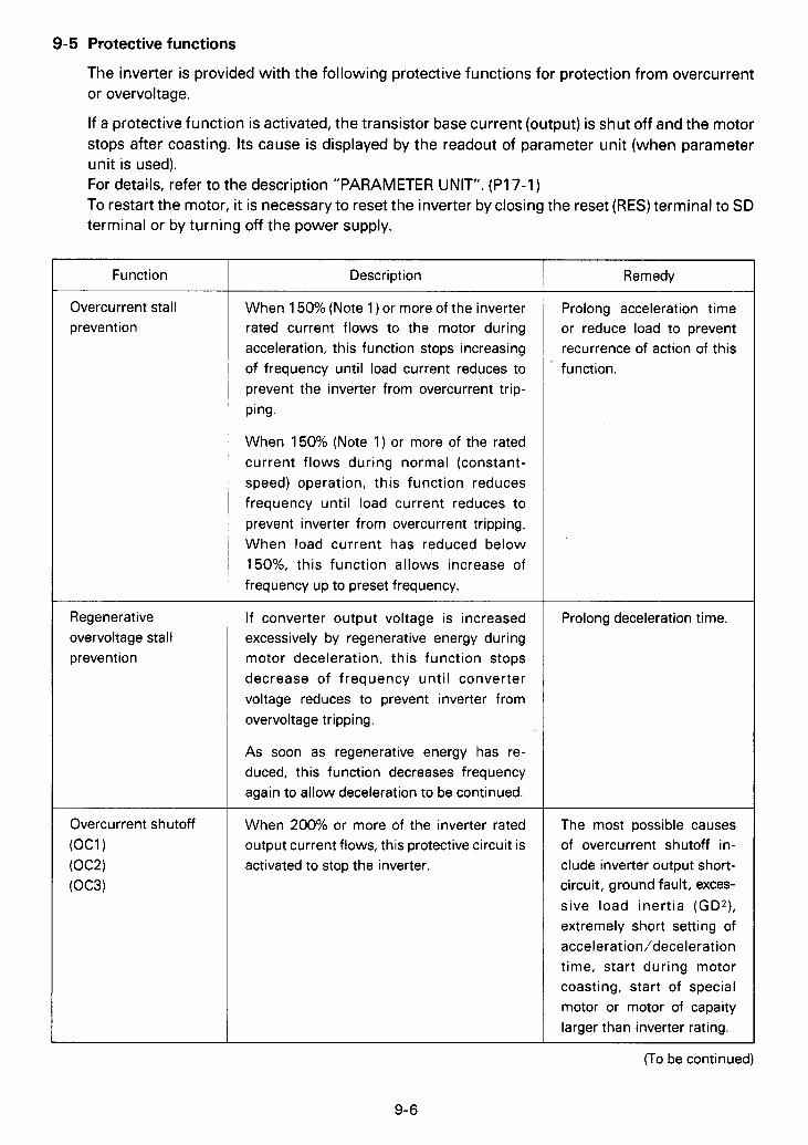
9-5 Protective functions
The inverter is provided with the following protective functions for protection from overcurrent or overvoltage.
If a protective function is activated, the transistor base current (output) is shut off and the motor stops after coasting. Its cause is displayed by the readout of parameter unit (when parameter unit is used). For details, refer to the description "PARAMETER UNIT". (P17-1) To restart the motor, it is necessary to reset the inverter by closing the reset (RES) terminal to SD terminal or by turning off the power supply.
Function
Overcurrent stall prevent ion
Regenerative overvoltage stall prevention
Description
When 150% (Note 1) or more of the inverter rated current flows to the motor during acceleration, this function stops increasing of frequency until load current reduces to prevent the inverter from overcurrent trip- ping.
When 150% (Note 1) or more of the rated current flows during normal (constant- speed) operation, this function reduces frequency until load current reduces to prevent inverter from overcurrent tripping. When load current has reduced below 150%, this function allows increase of frequency up to preset frequency.
If converter output voltage is increased excessively by regenerative energy during motor deceleration, this function stops decrease of frequency until converter voltage reduces to prevent inverter from overvoltage tripping.
As soon as regenerative energy has re- duced, this function decreases frequency again to allow deceleration to be continued.
When 200% or more of the inverter rated output current flows, this protective circuit is activated to stop the inverter.
Remedy
Prolong acceleration time or reduce load to prevent recurrence of action of this function.
Prolong deceleration time.
The most possible causes of overcurrent shutoff in- clude inverter output short- circuit, ground fault, exces- sive load inertia (GO*), extremely short setting of acceleration/deceleration time, start during motor coasting, start of special motor or motor of capaity larger than inverter rating.
(To be continued)
9-6
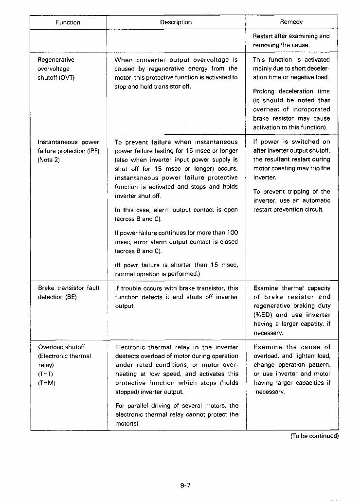
I Function
Regenerative overvoltage
Instantaneous power failure protection (IPF) (Note 2)
I------ Brake transistor fault detection (BE)
Overload shutoff (Electronic thermal relay) (THT)
Description
When converter output overvoltage is caused by regenerative energy from the motor, this protective function is activated to stop and hold transistor off.
To prevent failure when instantaneous power failure lasting for 15 msec or longer (also when inverter input power supply is shut off for 15 msec or longer) occurs, instantaneous power failure protective function is activated and stops and holds inverter shut off.
In this case, alarm output contact is open (across B and C).
If power failure continues for more than 100 msec, error alarm output contact is closed (across B and C).
(If powr failure is shorter than 15 msec, normal opration is performed.)
If trouble occurs with brake transistor, this function detects it and shuts off inverter output.
Electronic thermal relay in the inverter deetects overload of motor during operation under rated conditions, or motor over- heating at low speed, and activates this protective function which stops (holds stopped) inverter output.
For parallel driving of several motors, the electronic thermal relay cannot protect the motor(s).
Remedy
Restart after examining and removing the cause.
This function is activated mainly due to short deceler- ation time or negative load.
Prolong deceleration time (it should be noted that overheat of incroporated brake resistor may cause activation to this function).
If power is switched on after inverter output shutoff, the resultant restart during motor coasting may trip the inverter.
To prevent tripping of the inverter, use an automatic restart prevention circuit.
Examine thermal capacity of brake resistor and regenerative braking duty (%ED) and use inverter having a larger capatity, if necessary.
Examine the cause of overload, and lighten load, change operation pattern, or use inverter and motor having larger capacities if necessary.
(To be continued) -J
9-7

Function
Heatsink overheat protection (FIN)
Brake resistor overheat protection
Description
Provide a thermal relay on the inverter output side or fit thermistors in each motor.
In this case, the electronic thermal relay adjusted to OA position activates transistor protection only.
Models larger than 2.2K are equipped with cooling fan.
If the fan fails to rotate, rotation sensor is activated to shut off (hold shut off) inverter output.
If regenerative brake energy from motor has exceeded the specified value, the brake operation is stopped to protect the brake resistor from overheating.
When the brake resistor is cooled, the brake operation automatically restarts.
Remedy
Examine cooling fan opera- tion and ambient tempera- ture.
Prolong acceleration time or change operation se- quence to reduce braking duty.
Note 1 : The stall prevention threshold level is set to "1 50%" of inverter rated current when the inverter is shipped. This setting can be changed by user (the overcurrent stall prevention is activated at the threshold level set by user). Use this function parameter with care.
Note 2 : When inverter power supply circuit is opened or power failure occurs for more than 100 msec, the IPF lamp and error output contact are not activated.
Note 3 : When any protective function (except stall prevention, overload alarm, and brake resistor overheat protection) is activated, a relevant error indicator lamp lights and remain. By opening the inverter power supply circuit using a magnetic contactor (MC), etc., inverter control power is lost and the error signal cannot be held. To hold the error signal, hold the error output contact outside the inverter.
I. *.

9-6 External dimensions
B
11.81 (300)
1.1 1.1 1.1 2.68 4-40.67( 1 7) hole
BA C D H
0.27 1.93 11.02 3.94 (280) (100) (7) (49)
2-4D hole 7
Circuit breaker(MCCB1 Maanetic Inverter model con'iactor
(MC) Equipped with reactor(* 1 ) Standard
NF30 5A NF30 10A NF30 15A
NF30 5A NF30 10A NF30 15A
NF30 20A NF30 30A
NF30 15A S-K11 .K12 NF30 30A S-K20
FREQROL-ZIZ I Parameter
unit R - P U O 1 4
0
Note: When parameter unit FR-PUO1 E is not used, an accessory cover is installed in lieu of parameter unit.
Fig. 9-2 Unit : inch(mm)
8.66 7.87 FR-Zizo-0.75K(P)-UL 1 (220) 1 (200) 11.81 11.02 3.94 0.27 1.93 (300) I (280) 1 (100) I (7) I (49)
8.66 7.87 FR-Zizo-1.5K(P)-UL 1 (220) I (200) 0.27 3.1 1 11.81 11.02 5.12 (300) I (280) I (130) I (7) I (79) 11.81 11.02 6.69 0.27 4.69 (300) I (280) I (170) (7) 1 (119)
8.66 7.87 *FR-Zizo-3.7K(P)-UL I (220) I (200) 0.27 4.69 11.81 11.02 6.69 (300) I (280) I (170) I (7) 1 (119)
Models with mark * in the list are equipped with cooling fan.
9-7 Selection of peripheral devices
Moter output
(H P/kW)
0.5/0.4 1/0.75 2/1.5
FR-ZI 20-0.4K-U L FR-Z~ ZO-0.7 5 K-U L FR-Z120-1 .5K-UL
S-K10 S-K10 S-K10
3/2.2 5/3.7
FR-ZI 20-2.2K-UL FR-ZIZO-3. 7K-UL
Notes : * 1 .Equipped with power factor correction reactor FR-BAL(option). *2. Moter cable(U,V,W)size applies to 20m(66fi)or less wiring distance.
9-9
"8-
Inverter type
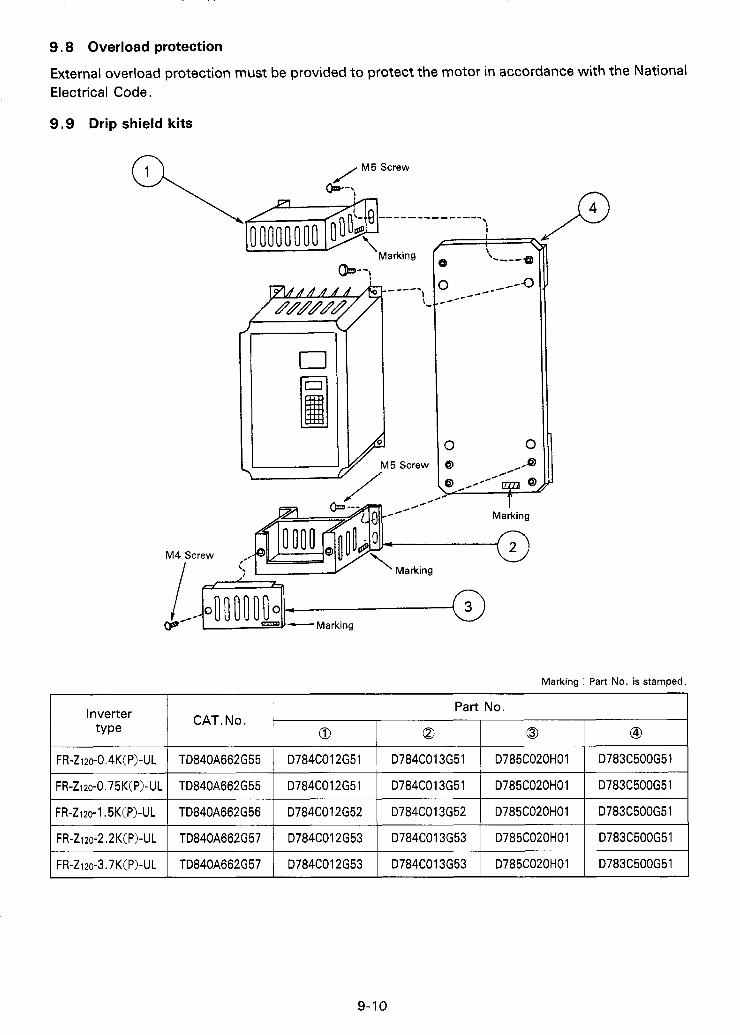
9.8 Overload protection
External overload protection must be provided to protect the motor in accordance with the National Electrical Code.
9.9 Drip shield kits
Part No. CAT.No.
0 0 0 GD
@"!
~~
FR-ZIZO-O.~K(P)-UL
FR-ZIZO-O.~~K(P)-UL
TD840A662G55 D784C012G51 D784C013G51 D785C020H01 D783C500G51
TD840A662G55 D784C012G51 D784C013G51 D785C020H01 D783C500G51
~
FR-ZI~O-~.~K(P)-UL
I FR-ZizO-I .5K(P)-UL I TD840A662G56 1 D784C012G52 I D784C013G52 I D785C020H01 I D783C500G51 I
TD840A662G57 D784C012G53 D784C013G53 D785C020H01 D783C500G51
I FR-Zi20-2.2K(P)-UL I TD840A662G57 1 D784C012G53 I D784C013G53 I D785C020H01 I D783C500G51 I

I PARAMETER UNIT I Parameter unit, model FR-PUO1 E, is directly attached to the inverter (FR-Z series), or connected to the inverter with the cable (option).
The parameter unit permits the operator to set (read and wirte) various control variables (parameters), and to monitor operation status through its readout.
In this manual, parameter unit is abbreviated as "PU".
T
51 1 INSTALLATION The PU can be directly attached to the inverter, or remotely installed and connected to the inverter with the approved cable. It can be attached or connected even when the inverter is operating . 0 Direct attachment to inverter
(1 ) Connection
Engage the plug of PU with the receptacle of inverter and gently press the PU against the inverter.
(2) Securing the PU in position
Lightly tighten two screws to secure the PU in position.
CAUTION: (1)
(2)
(3)
(4)
The PU should be attached to the inverter with the front cover installed on the inverter .
Never operate the inverter with the PU with the front cover removed. To prevent accidental damage to the inverter P.C.B and the PU unit.
If the inverter must be operated with the front cover removed, always use the approved extension cable with the PU unit.
Dangerous high voltages are present inside the inverter. Always use with great care and attention.
1 1 - 1
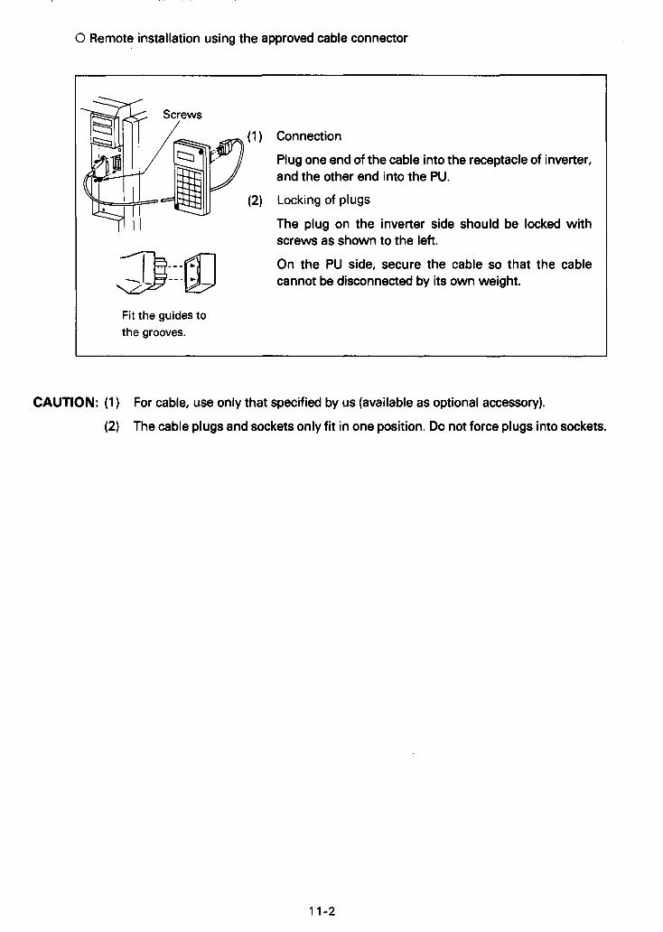
0 Remote installation using the approved cable connector
I
Fit the guides to the grooves.
Connection
Plug one end of the cable into the receptacle of inverter, and the other end into the PU.
Locking of plugs
The plug on the inverter side should be locked with screws as shown to the left.
On the PU side, secure the cable so that the cable cannot be disconnected by its own weight.
I
CAUTION: (1) For cable, use only that specified by us (available as optional accessory).
(2) The cable plugs and sockets only fit in one position. Do not force plugs into sockets.

91 2. OUTLINE OF FUNCTION
Function I Description
Selection of operation mode
"Parameter mode"
"External mode"
Setting (read/write) of control variables
(Monitor/alter)
Parameter unit can be used as control source for inverter operation
External signals can be used as control source for inverter operation.
Set control variable can be read.
Setting of control variable can be changed.
Keys of parameter unit are operated.
Separately installed frequency reference potentiometer, START switch, etc. are operated.
Settings are checked.
Change of setting
User's settings can be reset to the initial settings (settings made at shipment) . . . "ALL CLEAR".
Write parameter can be prohibited.
Frequency meter (indicator) can be calibrated.
~~~~ ~
Refer to
Page 14-2
Page 14-2
Page 15-1
Page 15-1
Page 15-1
Page 15-1
Monitor Operation status can be I Output frequency (Hz) I Page 16-1
Motor current (A) monitored.
Direction of rotation of motor
I Motor RUN I Alarm information I §16,§17
12-1

81 3. CONTROL DEVICES OF PARAMETER UNIT "ONLY LIGHT FINGER PRESSURE IS NECESSARY"
MOUNTING SCREW By loosening these two screws, the unit can be separated from the inverter. r - DISPLAY (READOUT)
Frequency, motor current, preset control variables, alarm message, etc. are displayed by this 4-digit readout.
VARIABLE INDICATOR LAMP Ir - 1 g
FR-PUO1 E PARAMETER UNIT e Control variable to be monitored (frequency, motor current, etc.) is indicated.
- OPERATION MODE INDICATOR LAMPS When an operation mode key (MONITOR, SET, EXT OP, PU OP) is pressed, the corresponding lamp lights.
. OPERATION MODE KEYS Operation mode can be selected from MONITOR, SET, EXT OP and PU OP. After operation mode is selected, desired control variable can be set, read (checked) or written (changed).
FREQUENCY ADJUST KEYS While it is held down, frequency continously increases or decreases. (Slowly at first, progressively faster)
OPERATION KEYS Motor rotating direction can be selected and operation can be stopped.
- READ/WRITE KEYS Variable setting can be read (checked) by pressing IREAD) and written (changed) by pressing [ml after ISET] key is pressed.
FUNCTION/NUMERAL KEYS Function No. of 1 st group function and value or freauencv can be mif ied. 1 I
- 2nd or 3rd group function key (2nd) When setting of 2nd or 3rd group function is read or written, this key is pressed. 3rd group function is selected by SHIFT KEY after this key is presed.
- SHIFTKEY Variable (frequency, motor current, alarm message) to be monitored is shifted or 3rd group function is Selected.
- CLEAR KEY If wrong key is pressed during setting, it can be cancelled by pressing this key.
13-1
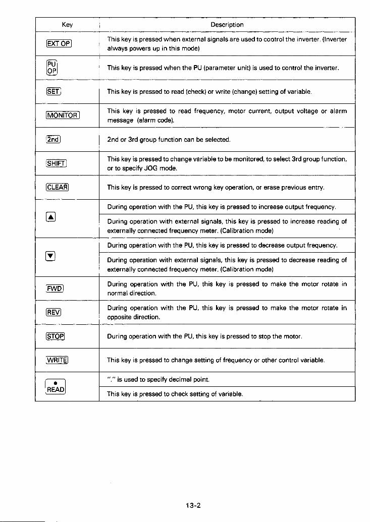
Key
(EXTOP]
Description
This key is pressed when external signals are used to control the inverter. (Inverter always powers up in this mode)
This key is pressed when the PU (parameter unit) is used to control the inverter
1 This key is pressed to read (check) or write (change) setting of variable.
[MoNlToR] This key is pressed to read frequency, motor current, output voltage or alarm message (alarm code).
2nd or 3rd group function can be selected.
This key is pressed to change variable to be monitored, to select 3rd group function, or to specify JOG mode.
[SHIFT]
This key is pressed to correct wrong key operation, or erase previous entry.
I During operation with the PU, this key is pressed to increase output frequency.
During operation with external signals, this key is pressed to increase reading of externally connected frequency meter. (Calibration mode)
1 During operation with the PU, this key is pressed to decrease output frequency.
During operation with external signals, this key is pressed to decrease reading of externally connected frequency meter. (Calibration mode)
[RNDJ During operation with the PU, this key is pressed to make the motor rotate in normal direction.
During operation with the PU, this key is pressed to make the motor rotate in opposite direction.
[STOP) During operation with the PU, this key is pressed to stop the motor.
[WRITE] This key is pressed to change setting of frequency or other control variable.
".'I is used to specify decimal point.
This key is pressed to check setting of variable. [Z]
13-2
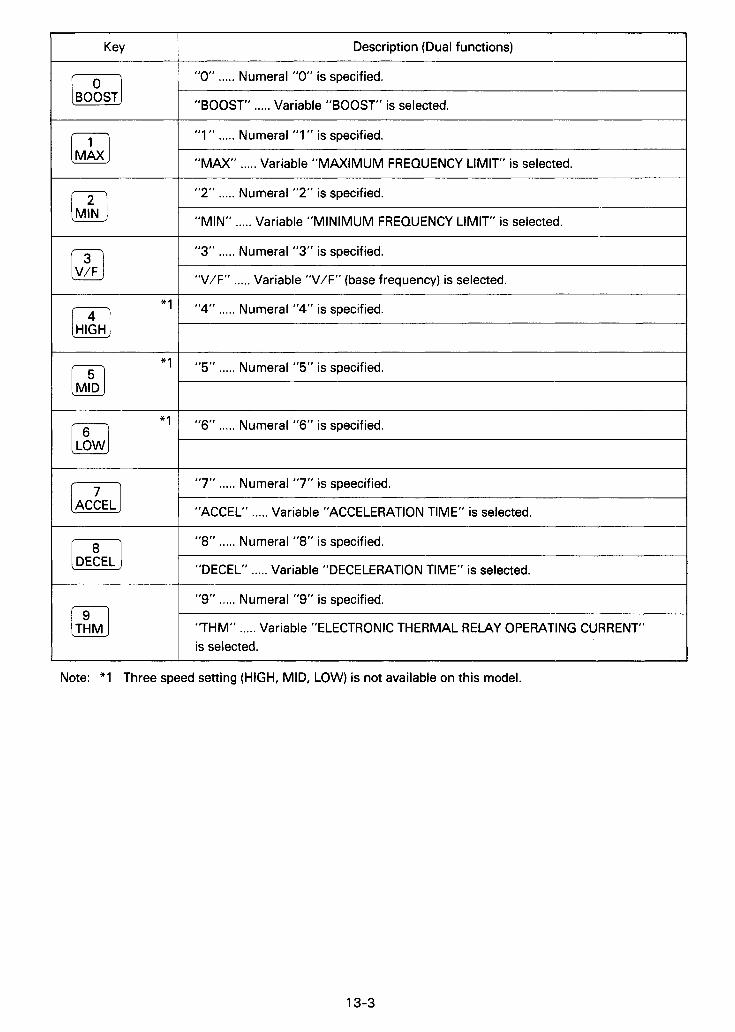
Key
[BO: ST]
Description (Dual functions)
"0" ..... Numeral "0" is specified.
"BOOST" ..... Variable "BOOST" is selected.
*'
"1 " ..... Numeral "1 " is specified.
"MAX" ..... Variable "MAXIMUM FREQUENCY LIMIT' is selected.
"2" ..... Numeral "2" is specified.
"MIN" ..... Variable "MINIMUM FREQUENCY LIMIT" is selected.
"4" ..... Numeral "4" is specified.
1 "3" ..... Numeral "3" is specified.
*'
I "V/F" ..... Variable "V/F" (base frequency) is selected.
"5" ..... Numeral "5" is specified.
/4j
"l
[HIGH J
"6" ..... Numeral "6" is specified.
1 "7" ..... Numeral "7" is speecified.
1 "ACCEL" ..... Variable "ACCELERATION TIME" is selected.
"8" ..... Numeral "8" is specified.
"DECEL" ..... Variable "DECELERATION TIME" is selected.
"9" ..... Numeral "9" is specified.
"THM" ..... Variable "ELECTRONIC THERMAL RELAY OPERATING CURRENT" is selected.
[DE: EL]
JTSHM] Note: *1 Three speed setting (HIGH, MID, LOW) is not available on this model.
13-3
,~ . , , . , ..,.." , . I , , , . .(,

Q14. OPERATION 14-1 Operation modes
The inverter can be operated either with external signals, or with PU (parameter unit).
Selection of operation mode (external signal mode or parameter mode) can be made by pressing key of PU.
It is possible to fix operation mode. (FUNCTION 79)
Operation with PU
4 Operation with external signals I 0 See 14-2
frequency (speed) setting
NFB inverter Motor n
4 0 F R - Z ~ ~ O
Start E51 i ri switch
I L J ’ I---I
inverter Motor
I 1 I Direct output I
frequeilcy
I I
1-1 JOG operation 1 0 See 14-3
INITIAL OPERATION MODE
When the power is turned on (or CLEAR key is pressed to reset), ”external signal operation” mode is automatically selected and the inverter can be operated with external signals ..... the motor starts when START signal (STF - SD or STR - SD closed) is given.
HOW TO FIX OPERATION MODE (FUNCTION 79)
Initial setting of operation mode can be changed so that ”PU operation” mode is automatically selected whenever the power is turned on.
For details, refer to 519
14-1

/"".
14-2 Operation with external signals
When "PU operation" mode has been selected, press [m] key to select "external signal operation" mode (check that the indicator lamp of selected operation mode lights).
Example of operation and indication I
oWhen the inverter is turned on or [m] key is pressed .....
oDuring operation with external frequency reference set at 30Hz .....
\ I ,e. o :e.' o
'e.' Hz
MONI- ITOR I SET I ous I ;: I
F d e : :@:and o show that lamp lights anc -3es not lis. .t respectively.
(1) When "external signal operation" mode is selected, "MONITOR" mode is automatically selected and output frequency is displayed by the readout (see $1 6).
(2) While inverter output is on (during rotation of the motor), the mode indicator lamp just above [m] key flickers (the same occurs druing DC dynamic brake operation).
CAUTION: Changing operation mode from "PU operation,, to "External signal operation"
Operation mode cannot be changed when START signal is on (STF - SD or STR - SD is closed).
Before changing operation mode, START signal should be turned off and it should be verified that the motor stops completely.
14-3 Operation with PU
To operate the inverter with the PU press Key.
After that, the inverter can be started and stopped by pressing keys of PU (without use of externally installed frequency reference potentiometer and START switch). In this operation mode, it is also possible to jog the motor by pressing keys of PU.
IMPORTANT NOTE
If the inverter is turned off or reset, operation mode changes from "PU operation" to "external signal operation" (initial mode setting).
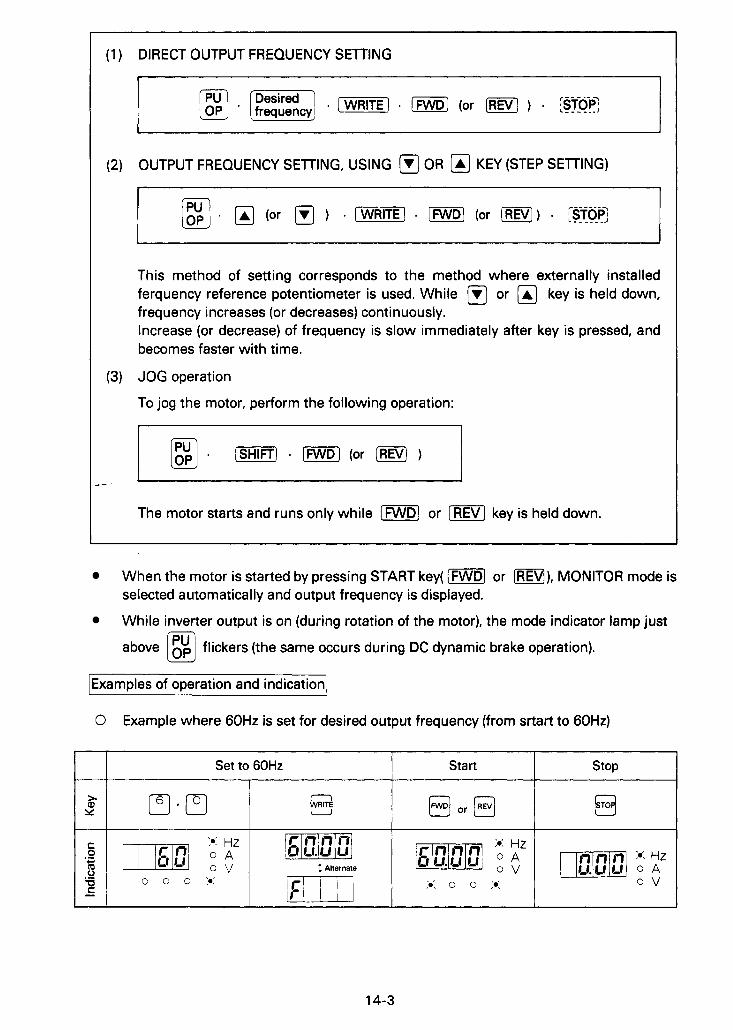
(1) DIRECT OUTPUT FREQUENCY SEl l ING
(2) OUTPUT FREQUENCY SElTING, USING OR @ KEY (STEP SElTlNG)
This method of setting corresponds to the method where externally installed ferquency reference potentiometer is used. While @ or key is held down, frequency increases (or decreases) continuously. Increase (or decrease) of frequency is slow immediately after key is pressed, and becomes faster with time.
(3) JOG operation
To jog the motor, perform the following operation:
r 1
The motor starts and runs only while (FWD] or [REV] key is held down.
When the motor is started by pressing START key( (m] or [REV]), MONITOR mode is selected automatically and output frequency is displayed.
While inverter output is on (during rotation of the motor), the mode indicator lamp just
above flickers (the same occurs during DC dynamic brake operation).
\Examples of operation and indication]
0 Example where 6OHz is set for desired output frequency (from srtart to 60Hz)
Set to 60Hz Start stop I
14-3
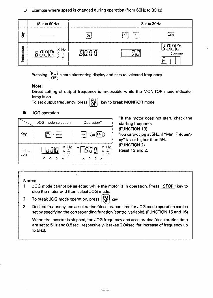
0 Example where speed is changed during operation (from 60Hz to 30Hz)
(Set to 6OHz) Set to 30Hz I I
n WRITE u
Indica- tion
Pressing @ clears alternating display and sets to selected frequency.
Note: Direct setting of output frequency is impossible while the MONITOR mode indicator lamp is on. To set output frequency, press key to break MONITOR mode.
0 JOG operation 'If the motor does not start, check the
(FUNCTION 13) You cannot jog at 5Hz, if "Min. Frequen- cy" is set higher than 5Hz.
JOG mode selection Operation* starting frequency.
@ (or@)
X Hz (FUNCTION 2) o Hz
o v o v [m] o A o A Reset 13 and 2.
I * 0 ° ' I 1 0 0 0 . I
l Notes: 1. JOG mode cannot be selected while the motor is in operation. Press (STOP] key to
stoD the motor and then select JOG mode.
2. To break JOG mode operation, press key
3. Desired frequency and acceleration/deceleration time for JOG mode operation can be set by specifying the corresponding function (control variable). (FUNCTION 15 and 16)
When the inverter is shipped, the JOG frequency and acceleration/deceleration time are set to 5Hz and 0.5sec., respectively (it takes 0.04sec. for increase of frequency up to 5Hz).
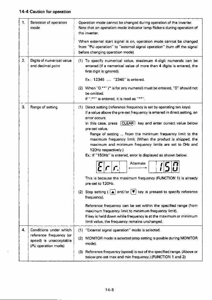
14-4 Caution for operation - 1.
2.
3.
4.
-
Selection of operation mode
Digits of numerical value and decimal point
Range of setting
Conditions under which reference frequency (or speed) is unacceptable (PU operation mode)
Operation mode cannot be changed during operation of the inverter. Note that an operation mode indicator lamp flickers during operation of the inverter.
When external start signal is on, operation mode cannot be changed from "PU operation" to "external signal operation" (turn off the signal before changing operation mode).
(1) To specify numerical value, maximum 4-digit numerals can be entered (if a nemerical value of more than 4 digits is entered, the first digit is ignored).
Ex.: 1 2345 ..... "2345" is entered.
(2) When "0.""" (* is for any numeral) must be entered, "0" should not be omitted. If " **" . is entered, it is read as "**".
Direct setting (reference frequency is set by operating ten keys) If a value above the pre-set frequency is entered in direct setting, an error occurs. In this case, press [CLEAR] key and enter correct value below pre-set value.
Range of setting ... From the minimum frequency limit to the maximum frequency limit. (When the product is shipped, the maximum and minimum frequency limits are set to OHz and 1 20Hz respectively.)
Ex.: If "1 50Hz" is entered, error is displayed as shown below.
This is because the maximum frequency (FUNCTION 1) is already pre-set to 120Hz.
Step setting ( @ and/or @ key is pressed to specify reference frequency).
Reference frequency can be set within the specified range (from maximum frequency limit to minimum frequency limit). If key is held down while frequency is at the maximum or minimum limit value, the frequency remains unchanged.
(1 ) "External signal operation" mode is selected.
(2) MONITOR mode is selected (step setting is posible during MONITOR mode).
(3) Reference frequency (speed) is out of the specified range. (Above or below pre-set max and min frequency.) (FUNCTION 1 and 2)
14-5
,-7 _I
[ l S t I Basic control
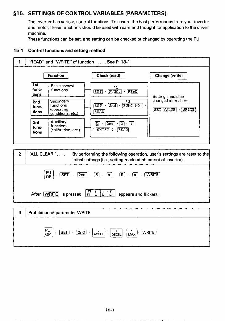
51 5. SETTINGS OF CONTROL VARIABLES (PARAMETERS) The inverter has various control functions. To assure the best performance from your inverter and motor, these functions should be used with care and thought for application to the driven machine. These functions can be set, and setting can be checked or changed by operating the PU.
I * ?
15-1 Control functions and setting method
func- tions
1 I ”READ” and ‘WRITE” of function . . . . . See P. 18-1
functions
2nd Secondary functions (operating conditions, etc.)
- @-@*[kJ- [READ_]
3rd func- tions
@.@*[Ol . I l ] ( [sHIFTJ ) * (READ] H Auxiliary
functions (calibration, etc.)
L I I ! I
3
I Change (write) J
Prohibition of parameter WRITE
Setting should be changed after check.
[-VALUE) - [WRITEJ
”ALL CLEAR” . . . . . By performing the following operation, user‘s settings are reset to the initial settings (i.e., setting made at shipment of inverter).
After -1 is pressed, -1 appears and flickers.
15-1
, , ,. , / ,_ “ . , * / , < (,,,,.. . , .*,, , ,
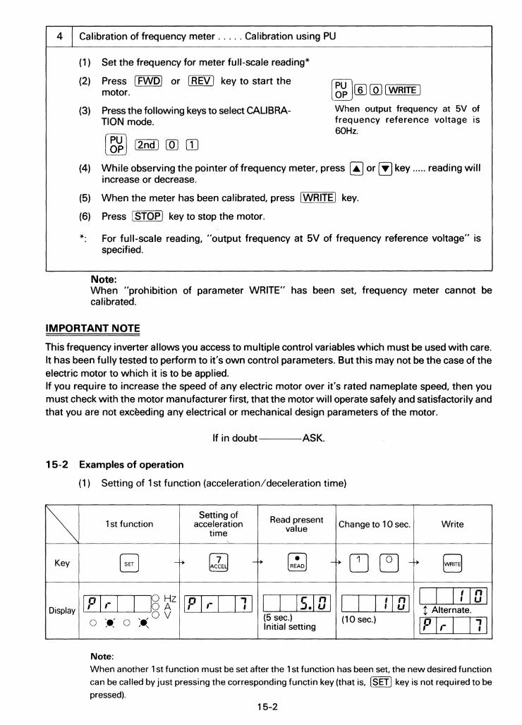

(2) Setting of 2nd function (frequency reference for JOG operation)
Setting of
JOG operation Selection of 2nd frequency for Read present Change to 10 Hz value function
Key @j -+ rJ I.:..1 -+ il_i PI -+
m i g f z ml mJ Display o v (5Hz) (1 OHz)
0 :.: 0 'r: Initial setting
Write
WRITE -+ 0
t n n n m.ml 2 Alternate.
(3) Setting of 3rd function (examples of bias and gain settings for frequency reference voltage signal)
- Gain Read lSet to 120Hz
I \ 1 Selection of 3rd function 1-
Write
~~ 4- Bias --I Read I Setto 10Hz I Write
Note: Do not input frequency reference signal across terminals 2 and 5.
Note: Do not input frequency reference signal or use 5V input signal.
For calibration of frequency meter, see P. 15-2.
15-3
I .

15-3 Caution
1
2
3
READ function
WRITE function
Selection of 3rd function
READ is possible in "external signal operation" mode as well as "PU operation" mode.
It is also possible even during operation of motor.
WRITE is possible only in "PU operation" mode.
It is impossible during operation of motor (setting of function No. 10 (PWM mode), however, can be changed during operation of motor).
READ and WRITE of 3rd function are possible only in "PU operation" mode.
Error appears when,
(1 ) WRITE is tried during operation of motor, or
(2) entered value is out of the specified range, or
(3) illegal function No. is set, or
(4) WRITE is tried during "external signal operation" mode, or
(5) WRITE is tried while parameter WRITE has been prohibited (see $1 5. and $1 9.).
Error condition can be cleared as follows:
(1) Press [CLEAR] key.
(2) If error is caused by setting illegal function No. (see §18.), press [SET] key.
15-4

§16. MONITOR
4- C
3 0
2
8
L
Y
f
Output frequency, motor current, direction of rotation of motor, and alarm condition can be monitored by performing operations described below.
MONITOR is possible after [m] key is pressed.
Operation
Inverter ouput frequency can be read by pressing [-I key.
Note: If a key is pressured during monitoring, MONITOR mode is cancelled and the preset output frequency id displayed.
Motor current can be read by pressing [m] key.
Note: Motor current during acceleration or deceleration can be also displayed. Displayed current, however, will not change if acceleration or deceleration is momentary.
Alarm code can be read by pressing [m] twice successively.
Notes: 1. The function is capable of storing a maximum
of four alarm codes. Stored alarm codes can be read one after another (see 57. for alarm codes).
How to read alarm codes
I D w l a y j - [READ] - JREAD] - (READ] r---- - - --- 7
a -' I 3rd 2nd 1 St
1 VI
alarm alarm I latest a,arm I-d_aLE - __I
0 When (READ) key is pressed, the latest
0 When (m] key is pressed, the output alarm code appears again.
frequency at the time is displayed.
2. Stored alarm codes are held even after the inverter is turned off.
Display example
:*: 0 0 0
0 Hz
:e: 0 0 0
(1) For the latest alarm, a dot is placed by after [(see an example shown above).
(2) If no alarm has been stored, the display is as shown below.
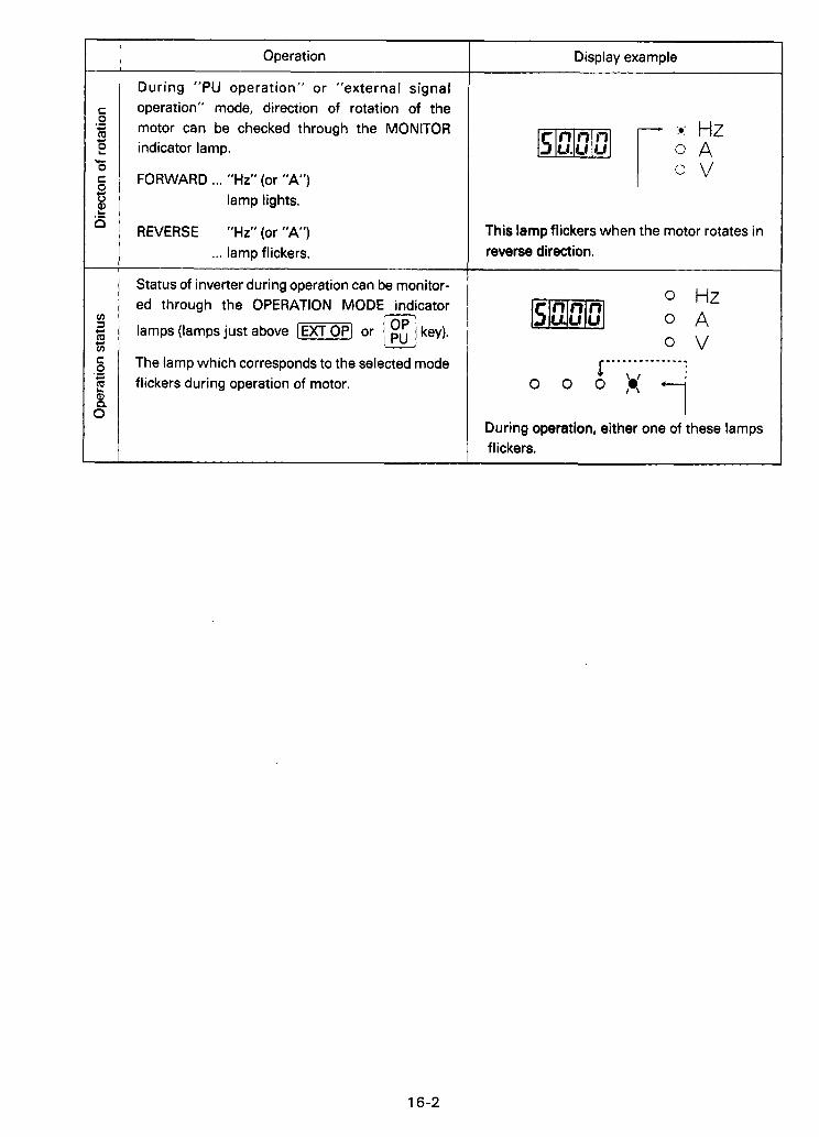
r Operation
During "PU operation" or "external signal operation" mode, direction of rotation of the motor can be checked through the MONITOR indicator lamp.
FORWARD ... "Hz" (or "A") lamp lights.
REVERSE "Hz"(or "A") ... lamp flickers.
Status of inverter during operation can be monitor- ed through the OPERATION MODE indicator
lamps (lamps just above [ W P ) or key).
The lamp which corresponds to the selected mode flickers during operation of motor.
Display example
This lamp flickers when the motor rotates in reverse direction.
o v
During operation, either one of these lamps flickers.
16-2

517. DISPLAY
17-1 Alarm display
If failure occurs during operation of the inverter, an alarm code is displayed automatically.
I Alarmcode Description
Code
EOC1 Inverter output current exceeded the overcurrent limit during acceleration.
EOC2 Inverter output current exceeded the overcurrent limit during constant-speed operation.
EOC3 Inverter output current exceeded the overcurrent limit during deceleration.
EOVT Braking regenerative power from motor exceeded the regenerative overvoltage limit.
Electronic thermal relay in the inverter was activated (current is below 150% of preset current).
~n r L U U I
ti'*" L I 0 1 ETHM
ETHT Electronic thermal relay in the inverter was activated (current is over 150% of preset current).
ElPF Instantaneous power failure protective function was activated.
EFlN Cooling fan failed to rotate.
I E t (E Brake transistor fault detection. E BE
EOLT Stall preventive function was activated during constant-speed operation and stopped the motor.
c n ~ r L U L I
I E PE E PE Memory in the inverter is corrupted.
7-2 Indicator lamps in MONITOR mode
I Indication Description
Frequency is displayed.
Motor current is displayed.
If stall preventive function is activated during MONITOR mode, all MODE lamps, other than that selected flicker.
I o v 1 Not used.
17-1
, . . , " . +, " . , ,..,../ , .,I,.
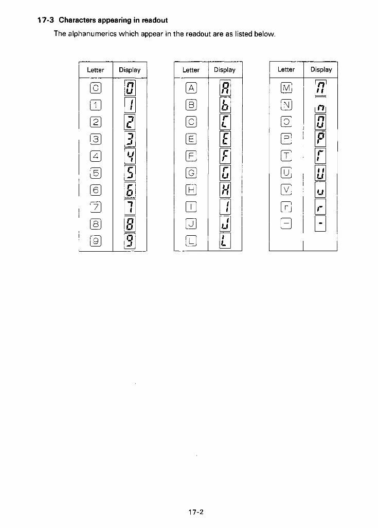
17-3 Characters appearing in readout
The alphanumerics which appear in the readout are as listed below.
Letter
,-
Display
(AI [Bl [cl [El El IGJ
I-
-<
17-2
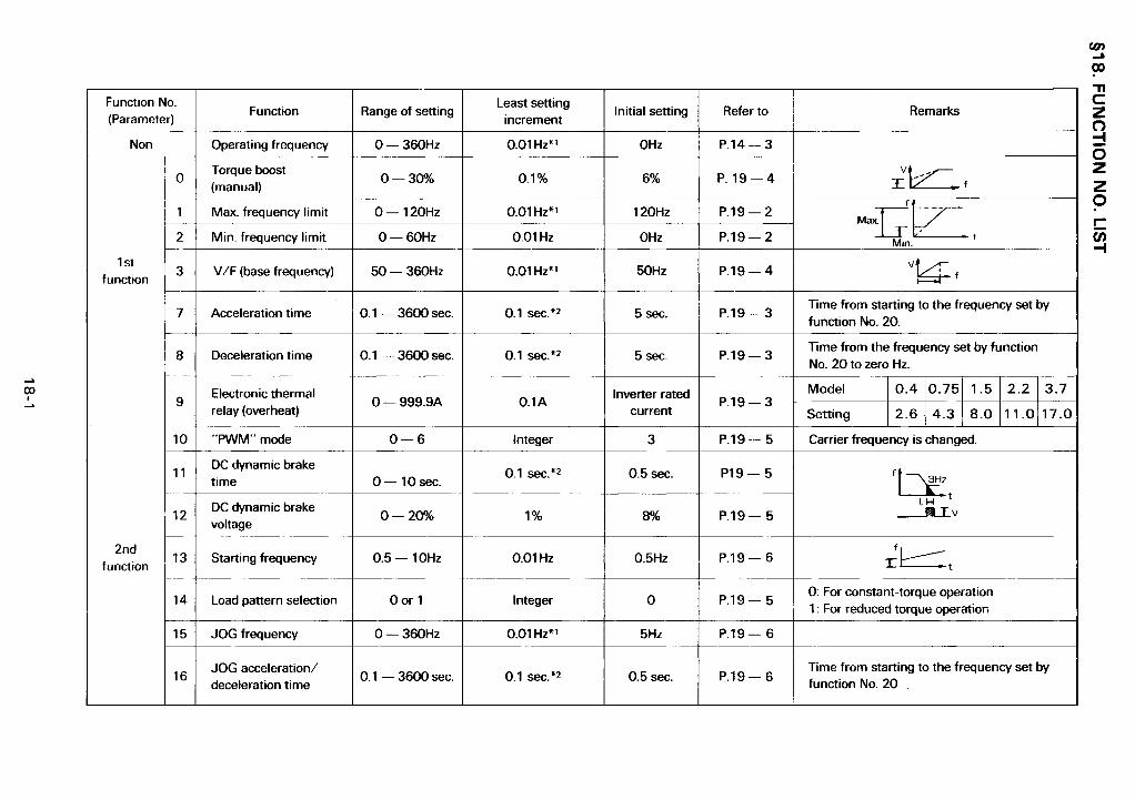
(D I 2 ti
In
(D
II
2
2
titi
518. FUN
CTIO
N N
O. LIS
T -
9 I- c -
B 3 2;
e
C a J e
H a 0
5 e
t I 2 ti -
g
UY I 2 ti -
g
t I z ti -
P %
m I z ti -
!i UY
0 I 2 ti -
d u)
In
m
(D I 2 ti
0
e
L
1
a K
I 2 ti
ci w 2
II
F !i c 0
2 v 0
w c 2 v 0
8 c
N
* d u)
c 0
a c 0 8
c
cn C
?= 0
a 0, C
.- 8 ,
d
v 8 :
I 0
P 3 I m
I 0
ur C a J .c
F a u) m U
e 3
0
I- co
Q,
c c
18-1

N I
Ei or e
g +
B C a J s E
E
.- X
m c
a v)
C 0
.- c 2 E ,o w J
- m
L
cn C
.- t: v) m a
v)
E
m I 2 d -
Li
0
I
hl I 2 d -
2 Ei e
hl I 2 d -
d
.- I 2
ti -
0
r- I 2 d -
d
F
I 2 d -
P 0
F
I 2 d -
d
e
I 2 d -
0
N
* 0:
0
a v)
.-
r
* P 2 P e. 0
8
c
rh
l
**
18-2


MAXIMUM OUTPUT FREQUENCY SETTING
Frequency with reference voltage signal at 5V (21 101 A
Output frequency at DC5V of frequency reference signal can be set. That is, the maximum output frequency in "external signal operation" mode is set.
acceleration or deceleration up to the maximum
2
frequency Acceleration/deceleration time is the time taken for 5 n range
2 frequency. 5v
Frequency reference signal
Note: The set maximum frequency changes automatically when setting of "gain for frequency reference voltage signal" (see p. 15-3) is changed. Since this function has the priority level same as that of 3rd function (C-3), priority is given to the latest set function, when this function is set together with a 3rd function.
MAXIMUM/MINIMUM FREQUENCY LIMIT
Maximum frequency limit [II Minimum frequency limit (21
Output frequency can be clamped to desired maxi- mum and/or minimum frequency.
Notes: 1. When minimum limit frequency is set, it should 2
t
71- ' setting range 1-
Max. limit frequency
be higher than the starting frequency (see "Start- ing frequency setting", P. 19-6).
setting range
2. Maximum limit frequency may not be higher 5v than 120Hz. Frequency reference signal
High-speed maximum frequency limit [II 18]
Maximum limit frequency can be set to a frequency higher than 120Hz for exceptionally high- speed operation. The maximum frequency limit set by the 1 st function is overriden by this setting.
19-2
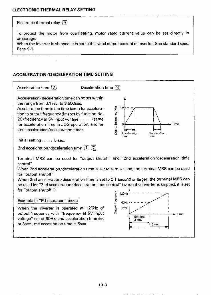
ELECTRONIC THERMAL RELAY SETTING
Electronic thermal relay 19] i n -
., - 7,.
To protect the motor from overheating, motor rated current value can be set directly in amperage. When the inverter is shipped, it is set to the rated output current of inverter. See standard spec. Page 9-1.
ACCELER AT10 N /D ECELER ATlON TIM E S E T 1 N G
Acceleration time [7j Deceleration time @
N f m - -
J
Time
i h-\ ~
Acceleration/deceleration time can be set within the range from 0.1 sec. to 3,600sec. Acceleration time is the time taken for accelera- tion to output frequency (fm) set by function No. 20 (frequency at 5V input voltage) . . . . . (same for acceleration time in JOG operation, and for 'c F 2nd acceleration/deceleration time). 2 a U 5 Acceleration Deceleration
time time Initial setting . . . . . 5 sec.
2nd acceleration/deceleration time [II [7)
Terminal MRS can be used for "output shutoff" and "2nd acceleration/deceleration time control". When 2nd acceleration/deceleration time is set to zero second, the terminal MRS can be used for "output s h u toff ". When 2nd acceleration/deceleration time is set to 0.1 second or larger, the terminal MRS can be used for "2nd acceleration/deceleration time control" (when the inverter is shipped, it is set
k for "output shutoff ". )
Examole in "PU ooeration" mode +- 3 a When the inverter is operated at 120Hz of *
output frequency with "frequency at 5V input voltage" set at 60Hz, and acceleration time set at 3sec.. the acceleration time is Gsec.
5
A
Time Set time

MOTOR TORQUE ADJUSTING (TORQUE BOOST)
Torque boost (manual) lo]
Motor torque in the low-frequency range can be adjusted to motor load.
I - output Base frequency frequency (Hz)
Initial setting . . . . . 6%
Note: If setting is excessively large, overcurrent trip may occur. It is recommended to set while observing motor current (use MONITOR function).
VOLTAGE/FREQUENCY (V/F) CHARACTERISTIC SElTlNG
V/F (base frequency) [31
Base frequency (frequency at the rated motor torque) can be set in accordance with the motor rating within the range from 50Hz to 360Hz.
Base frequency setting range
- 100%)
output voltage
1 I I
50 fb (Base frequency) 360 --
Output frequency (k)
19-4

LOAD PAlTERN SELECTION
Load pattern selection [m [41 V/F characteristic which match load characteristic can be selected.
Setting "0" (initial setting)
For constant-torque load (conveyor, carriage, etc.)
V
Base frequency Output frequency (Hz)
Setting "1 "
For reduced torque IoaG (fan, pump, etc.)
4
voltage o : : [ -
Base frequency Output frequency (Hz)
Desired V/F characteristic can be obtained by co-ordinating this setting with "torque boost" and "V/F" settings.
PWM MODE
PWM mode [i-][o] By changing carrier frequency (hertz), motor sound and vibration can be reduced. 8OHz per
Carrier frequency, low graduation change.
One of 7 carrier frequencies can be selected.
Note: Initial setting is "3".
Carrier frequency, high
DC DYNAMIC BRAKE SETTING
DC dynamic brake time [l]l-i-] DC dynamic brake voltage [i7[2]
c
P c Accuracy in stop position can be adjusted by a 3HZ setting the DC dynamic brake torque (voltage) and braking time (time taken for braking). 1 - Time
Time
The DC dynamic brake is turned on when output frequency is blow 3Hz.
Notes: Ij 1. When DC dynamic brake is not required, set brake time to "0". Operating time
2. If speed is decelerated by decreasing frequency reference signal voltage (or by pressing key), the DC dynamic brake starts operating at 0.5Hz of output frequency (initial
setting)
Initial setting of DC dynamic brake voltage . . . . . 8% 3.
19-5
, I I . ,, . , . . , , , ,.l.l., . ~ . ,.,.

STARTING FREQUENCY SETTING
Starting frequency [T][3]
Frequency for start of motor operation can be set within the range from 0.5Hz to 1 OHz.
output frequency
Inverter output 7 10 - - Setting range I / i
I t Frequency reference signal (V)
SETTING FOR JOG OPERATION
Jog frequency [TI [z) JOG operation can be realized by selecting JOG mode on PU.
When the motor is jogged without changing the initial (shipping) setting, the time taken for acceleration or deceleration is 0.04sec.
Jog accel./decel. time [TIE]
I
I I
REGENERATIVE BRAKE DUTY (%ED) SETTING
Regenerative brake duty [%1[5]
Duty imposed on discharge resistor for regenerative braking can be set. For exceptionally arduous duty, use of resistors having a larger capacity should be considerd.
Initial setting . . . . . 3%
STALL PREVENTION LEVEL SETTING
Stall prevention level [FIlT] When a small-capacity motor (as compared with capacity of inverter) is driven by a large- capacity inverter, overload (excessively large torque) can be prevented by changing current level at which the stall preventive function is activated.
150%
120%
Time
Notes: 1 . Operating current (%) is a ratio of the set current
to the rated output current of the inverter. 2. Least setting increment: 10% 3. When setting is zero, the stall preventive function
is not activated.
Operating current (%)
19-6

_. F"
* ! ,
FREQUENCY METER CALIBRATION
Frequency meter 1 mA full scale
FM
so
Frequency meter calibration IC-11 Frequency meter can be calibrated, without use of calibration potentiometer, by operating the PU. (For method refer to 15-1).
Note: The initial setting is that 1mA full scale is read and pulse train signal frequency is 1440Hz when the output frequency is 60Hz.
OUTPUT FREQUENCY ADJUSTMENT
- Bias for frequency reference voltage signal [c-21 E 2
Gain for frequency reference voltage signal [c-3j z
Output frequency ramp for frequency reference signal can be set.
Output frequency can be set for frequency refer- ence signal input through terminals 2 and 5.
GAIN
f-
Frequency reference signal 5v Output frequency can be set for frequency refer- ence signal input through terminals 2 and 5. When frequency reference signal is OV, the signal is judged to be 5V.
*When this gain is specified, value set for "frequency at 5V input voltage" (function No.20) is changed correspondingly.
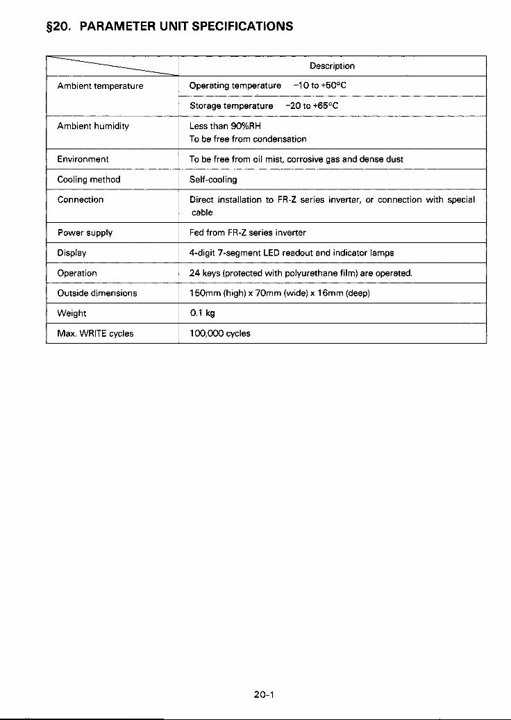
520. PARAMETER UNIT SPECIFICATIONS
Description
Ambient temperature Operating temperature -1 0 to +5OoC
Storage temperature -20 to t65OC
h
Ambient humidity
Environment
Less than 90%RH To be free from condensation
To be free from oil mist, corrosive gas and dense dust
I Operation
Cooling method
Connection
Power supply
Display
1 24 keys (protected with polyurethane film) are operated.
Self -cooling
Direct installation to FR-2 series inverter, or connection with special cable
Fed from FR-2 series inverter
4-digit 7-segment LED readout and indicator lamps
Outside dimensions
Weight
I Max. WRITE cycles
150mm (high) x 70mm (wide) x 16mm (deep)
0.1 kg
,-
20- I

§21. PARAMETER UNIT OUTSIDE DIMENSIONS, CABLE DETAILS
0 Parameter unit (PU)
-I-& MiTSUBlSHi -C
0 Cable (option)
2-63.5 I
I T I L 1
2-M3 screw
(Unit: mm)
inverter side Parameter unit side
1 FR-CBL03 I 3 I I FR-CBL05 I 5 I
21-1
$7' ' - . ' I ' .. * ,", ,,, . _*. .. . .. . .,.,. ,, . " . I . I , ,

A MlTSUBlSHl ELECTRIC CORPORATION HEAD OFFICE: MlTSUBlSHl DENKI BLDG. MARUNOUCHI TOKYO 100 TELEX: J24532 CABLE MELCO TOKYO
IB(NA)-66208. A(8906) ROD Printed in Japan Specification subject to change without notice.