
Mitsubishi Electric Air Conditioning Network System ... · Mitsubishi Electric Air Conditioning...
128
Mitsubishi Electric Air Conditioning Network System Centralized Controller G-50A and Integrated Centralized Control Software TG-2000A Technical Manual
Transcript of Mitsubishi Electric Air Conditioning Network System ... · Mitsubishi Electric Air Conditioning...

Mitsubishi Electric Air Conditioning Network SystemCentralized Controller G-50A and Integrated Centralized Control Software TG-2000A Technical Manual

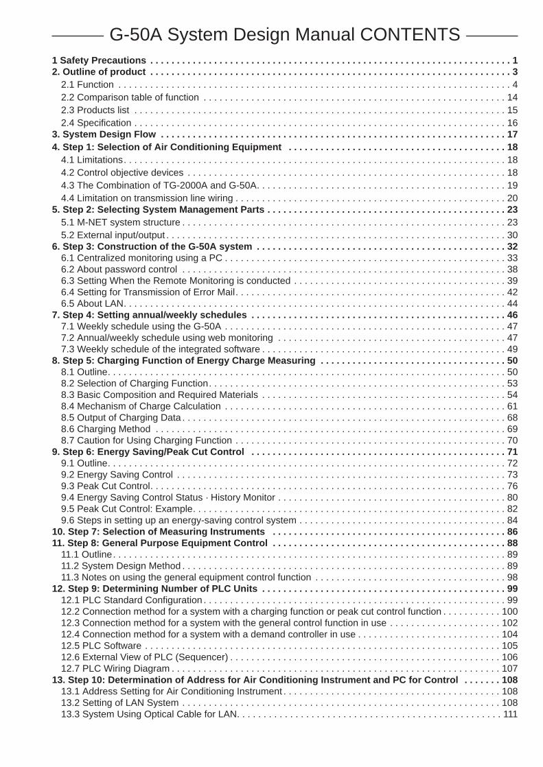
G-50A System Design Manual CONTENTS1 Safety Precautions . . . . . . . . . . . . . . . . . . . . . . . . . . . . . . . . . . . . . . . . . . . . . . . . . . . . . . . . . . . . . . . . . . . . 12. Outline of product . . . . . . . . . . . . . . . . . . . . . . . . . . . . . . . . . . . . . . . . . . . . . . . . . . . . . . . . . . . . . . . . . . . . 3
2.1 Function . . . . . . . . . . . . . . . . . . . . . . . . . . . . . . . . . . . . . . . . . . . . . . . . . . . . . . . . . . . . . . . . . . . . . . . . . . 42.2 Comparison table of function . . . . . . . . . . . . . . . . . . . . . . . . . . . . . . . . . . . . . . . . . . . . . . . . . . . . . . . . . 142.3 Products list . . . . . . . . . . . . . . . . . . . . . . . . . . . . . . . . . . . . . . . . . . . . . . . . . . . . . . . . . . . . . . . . . . . . . . 152.4 Specification . . . . . . . . . . . . . . . . . . . . . . . . . . . . . . . . . . . . . . . . . . . . . . . . . . . . . . . . . . . . . . . . . . . . . . 16
3. System Design Flow . . . . . . . . . . . . . . . . . . . . . . . . . . . . . . . . . . . . . . . . . . . . . . . . . . . . . . . . . . . . . . . . . 174. Step 1: Selection of Air Conditioning Equipment . . . . . . . . . . . . . . . . . . . . . . . . . . . . . . . . . . . . . . . . . 18
4.1 Limitations. . . . . . . . . . . . . . . . . . . . . . . . . . . . . . . . . . . . . . . . . . . . . . . . . . . . . . . . . . . . . . . . . . . . . . . . 184.2 Control objective devices . . . . . . . . . . . . . . . . . . . . . . . . . . . . . . . . . . . . . . . . . . . . . . . . . . . . . . . . . . . . 184.3 The Combination of TG-2000A and G-50A. . . . . . . . . . . . . . . . . . . . . . . . . . . . . . . . . . . . . . . . . . . . . . . 194.4 Limitation on transmission line wiring . . . . . . . . . . . . . . . . . . . . . . . . . . . . . . . . . . . . . . . . . . . . . . . . . . . 20
5. Step 2: Selecting System Management Parts . . . . . . . . . . . . . . . . . . . . . . . . . . . . . . . . . . . . . . . . . . . . . 235.1 M-NET system structure . . . . . . . . . . . . . . . . . . . . . . . . . . . . . . . . . . . . . . . . . . . . . . . . . . . . . . . . . . . . . 235.2 External input/output . . . . . . . . . . . . . . . . . . . . . . . . . . . . . . . . . . . . . . . . . . . . . . . . . . . . . . . . . . . . . . . . 30
6. Step 3: Construction of the G-50A system . . . . . . . . . . . . . . . . . . . . . . . . . . . . . . . . . . . . . . . . . . . . . . . 326.1 Centralized monitoring using a PC . . . . . . . . . . . . . . . . . . . . . . . . . . . . . . . . . . . . . . . . . . . . . . . . . . . . . 336.2 About password control . . . . . . . . . . . . . . . . . . . . . . . . . . . . . . . . . . . . . . . . . . . . . . . . . . . . . . . . . . . . . 386.3 Setting When the Remote Monitoring is conducted . . . . . . . . . . . . . . . . . . . . . . . . . . . . . . . . . . . . . . . . 396.4 Setting for Transmission of Error Mail. . . . . . . . . . . . . . . . . . . . . . . . . . . . . . . . . . . . . . . . . . . . . . . . . . . 426.5 About LAN. . . . . . . . . . . . . . . . . . . . . . . . . . . . . . . . . . . . . . . . . . . . . . . . . . . . . . . . . . . . . . . . . . . . . . . . 44
7. Step 4: Setting annual/weekly schedules . . . . . . . . . . . . . . . . . . . . . . . . . . . . . . . . . . . . . . . . . . . . . . . . 467.1 Weekly schedule using the G-50A . . . . . . . . . . . . . . . . . . . . . . . . . . . . . . . . . . . . . . . . . . . . . . . . . . . . . 477.2 Annual/weekly schedule using web monitoring . . . . . . . . . . . . . . . . . . . . . . . . . . . . . . . . . . . . . . . . . . . 477.3 Weekly schedule of the integrated software . . . . . . . . . . . . . . . . . . . . . . . . . . . . . . . . . . . . . . . . . . . . . . 49
8. Step 5: Charging Function of Energy Charge Measuring . . . . . . . . . . . . . . . . . . . . . . . . . . . . . . . . . . . 508.1 Outline. . . . . . . . . . . . . . . . . . . . . . . . . . . . . . . . . . . . . . . . . . . . . . . . . . . . . . . . . . . . . . . . . . . . . . . . . . . 508.2 Selection of Charging Function. . . . . . . . . . . . . . . . . . . . . . . . . . . . . . . . . . . . . . . . . . . . . . . . . . . . . . . . 538.3 Basic Composition and Required Materials . . . . . . . . . . . . . . . . . . . . . . . . . . . . . . . . . . . . . . . . . . . . . . 548.4 Mechanism of Charge Calculation . . . . . . . . . . . . . . . . . . . . . . . . . . . . . . . . . . . . . . . . . . . . . . . . . . . . . 618.5 Output of Charging Data . . . . . . . . . . . . . . . . . . . . . . . . . . . . . . . . . . . . . . . . . . . . . . . . . . . . . . . . . . . . . 688.6 Charging Method . . . . . . . . . . . . . . . . . . . . . . . . . . . . . . . . . . . . . . . . . . . . . . . . . . . . . . . . . . . . . . . . . . 698.7 Caution for Using Charging Function . . . . . . . . . . . . . . . . . . . . . . . . . . . . . . . . . . . . . . . . . . . . . . . . . . . 70
9. Step 6: Energy Saving/Peak Cut Control . . . . . . . . . . . . . . . . . . . . . . . . . . . . . . . . . . . . . . . . . . . . . . . . 719.1 Outline. . . . . . . . . . . . . . . . . . . . . . . . . . . . . . . . . . . . . . . . . . . . . . . . . . . . . . . . . . . . . . . . . . . . . . . . . . . 729.2 Energy Saving Control . . . . . . . . . . . . . . . . . . . . . . . . . . . . . . . . . . . . . . . . . . . . . . . . . . . . . . . . . . . . . . 739.3 Peak Cut Control. . . . . . . . . . . . . . . . . . . . . . . . . . . . . . . . . . . . . . . . . . . . . . . . . . . . . . . . . . . . . . . . . . . 769.4 Energy Saving Control Status · History Monitor . . . . . . . . . . . . . . . . . . . . . . . . . . . . . . . . . . . . . . . . . . . 809.5 Peak Cut Control: Example. . . . . . . . . . . . . . . . . . . . . . . . . . . . . . . . . . . . . . . . . . . . . . . . . . . . . . . . . . . 829.6 Steps in setting up an energy-saving control system . . . . . . . . . . . . . . . . . . . . . . . . . . . . . . . . . . . . . . . 84
10. Step 7: Selection of Measuring Instruments . . . . . . . . . . . . . . . . . . . . . . . . . . . . . . . . . . . . . . . . . . . . 8611. Step 8: General Purpose Equipment Control . . . . . . . . . . . . . . . . . . . . . . . . . . . . . . . . . . . . . . . . . . . . 88
11.1 Outline. . . . . . . . . . . . . . . . . . . . . . . . . . . . . . . . . . . . . . . . . . . . . . . . . . . . . . . . . . . . . . . . . . . . . . . . . . 8911.2 System Design Method . . . . . . . . . . . . . . . . . . . . . . . . . . . . . . . . . . . . . . . . . . . . . . . . . . . . . . . . . . . . . 8911.3 Notes on using the general equipment control function . . . . . . . . . . . . . . . . . . . . . . . . . . . . . . . . . . . . 98
12. Step 9: Determining Number of PLC Units . . . . . . . . . . . . . . . . . . . . . . . . . . . . . . . . . . . . . . . . . . . . . . 9912.1 PLC Standard Configuration . . . . . . . . . . . . . . . . . . . . . . . . . . . . . . . . . . . . . . . . . . . . . . . . . . . . . . . . . 9912.2 Connection method for a system with a charging function or peak cut control function . . . . . . . . . . . 10012.3 Connection method for a system with the general control function in use . . . . . . . . . . . . . . . . . . . . . 10212.4 Connection method for a system with a demand controller in use . . . . . . . . . . . . . . . . . . . . . . . . . . . 10412.5 PLC Software . . . . . . . . . . . . . . . . . . . . . . . . . . . . . . . . . . . . . . . . . . . . . . . . . . . . . . . . . . . . . . . . . . . 10512.6 External View of PLC (Sequencer) . . . . . . . . . . . . . . . . . . . . . . . . . . . . . . . . . . . . . . . . . . . . . . . . . . . 10612.7 PLC Wiring Diagram . . . . . . . . . . . . . . . . . . . . . . . . . . . . . . . . . . . . . . . . . . . . . . . . . . . . . . . . . . . . . . 107
13. Step 10: Determination of Address for Air Conditioning Instrument and PC for Control . . . . . . . 10813.1 Address Setting for Air Conditioning Instrument . . . . . . . . . . . . . . . . . . . . . . . . . . . . . . . . . . . . . . . . . 10813.2 Setting of LAN System . . . . . . . . . . . . . . . . . . . . . . . . . . . . . . . . . . . . . . . . . . . . . . . . . . . . . . . . . . . . 10813.3 System Using Optical Cable for LAN. . . . . . . . . . . . . . . . . . . . . . . . . . . . . . . . . . . . . . . . . . . . . . . . . . 111

14. Step 11: Confirmation of Other Functions . . . . . . . . . . . . . . . . . . . . . . . . . . . . . . . . . . . . . . . . . . . . . 11214.1 Personal Web Function . . . . . . . . . . . . . . . . . . . . . . . . . . . . . . . . . . . . . . . . . . . . . . . . . . . . . . . . . . . . 11214.2 Trend Data Output Function . . . . . . . . . . . . . . . . . . . . . . . . . . . . . . . . . . . . . . . . . . . . . . . . . . . . . . . . 114
15. Initial Setting Tool . . . . . . . . . . . . . . . . . . . . . . . . . . . . . . . . . . . . . . . . . . . . . . . . . . . . . . . . . . . . . . . . . 11915.1 What is the Initial Setting Tool? . . . . . . . . . . . . . . . . . . . . . . . . . . . . . . . . . . . . . . . . . . . . . . . . . . . . . . 11915.2 Composition of Initial Setting Tool. . . . . . . . . . . . . . . . . . . . . . . . . . . . . . . . . . . . . . . . . . . . . . . . . . . . 120
16. Other function . . . . . . . . . . . . . . . . . . . . . . . . . . . . . . . . . . . . . . . . . . . . . . . . . . . . . . . . . . . . . . . . . . . . 12216.1 Auto-Changeover Function (Automatic Changeover of Cooling/Heating Operation) . . . . . . . . . . . . . 122

1
1. Safety Precautions● Before using this unit, be sure you read “Safety Precaution” carefully for proper usage.● The “Safety Precautions” provide very important points regarding safety. Make sure you follow them.● Danger caused by erroneous operation and the resultant degree are classified in the following table.
Describes the items that cause serious danger of injury or death.
Describes the items that cause danger of injury or damage of household effects.
WARNING
CAUTION
NOTE: When handling your PC, peripheral equipment or air conditioning equipment, please observethe warning and cautions of the installation manual and instruction manual.
WARNING
The user should never attempt to conductinstallation work or electrical/wiring work.Ask these works for a specialist. Improper workmay cause an electric shock or fire.
Confirm that the power source is of thecorrect-rated capacity.Neglecting this may cause a fire or machine trouble.
Never attempt to reform or repair by yourself.Improper reform or repair may cause an electricshock or fire. For repair, ask your dealer.
Stop operation at an abnormal state.Continuing operation under abnormal state maycause an electric shock or fire. At abnormalstate, stop operation and contact your dealer.
Do not dispose the unit by yourself.To dispose the unit, ask your dealer.
For your PC or peripheral equipment, readthe installation manual and instructionmanual carefully.Erroneous handling may cause the fire andmachine trouble of the PC or peripheralequipment.
CAUTION
Do not place any dangerous matter aroundthe unit.Do not install the unit at a place wherecombustible gas may leak. Gas if stagnatedaround the unit may cause a fire or explosion.
Do not wash the unit with water.This may cause an electric shock or machinetrouble.
Do not spray pesticide or combustible gas tothe unit.Refrain from placing combustible spray can nearthe unit or spray it directly to the unit.Otherwise a fire or explosion may be caused.
Do not use the unit in a special environment.Using in a place with much machine oil, steam orsulfur gas may deteriorate the performance ordamage parts.
Do not press the switch with sharp edges.This may cause an electric shock or machinetrouble.
Do not use for a special purpose.This product is designed for Mitsubishi BuildingAir Conditioning Management system. Do notuse for other air conditioners or applications.Neglecting this may cause erroneous operation.
Confirm installation status. Confirm that the unit is fastened at a stableposition not to allow it to fall down easily.
Do not move the unit by yourself.Improper installation may cause an electricshock or fire. Ask your dealer.
Please read the installation manual andinstruction manual of air conditionercontrollers.Erroneous handling may cause the fire or troubleof the controllers relating to the air conditioner.

2
CAUTION
Do not touch the button with wet fingers.An electric shock or machine trouble may becaused.
Do not disassemble this unit.This may provide danger to touch the internalcircuit board, or cause machine trouble.
Do not wipe the unit with benzene, thinner orchemical waste.Neglecting this may change the color or causemachine trouble. When it is seriously dirty, firstremove it with a squeezed cloth once dampedwith neutral detergent dissolved in water, andthen clean with a dry cloth.
Do not use software other than TG-2000A forcomputers with TG-2000A.Using other application software may cause amalfunction.
When installing the unit in a hospital or communication station, provide sufficient protectionagainst noise.Erroneous operation or machine trouble may be caused by the effect of inverter equipment, privatepower generator, high-frequency medical equipment, wireless communication equipment, etc.Conversely the unit may affect such equipment, creating noise to disturb medical treatment or imagebroadcasting.
Please observe the operating temperaturerange.Using under the environment outside of theoperating temperature range may cause aserious trouble. Confirm the operatingtemperature range by the specification in theinstruction manual. If not listed, use a range of 0~ 40°C.
Do not draw or twist the transmission line.Neglecting this may cause a fire or machinetrouble.
Use a standard wire meeting the currentcapacity for wiring.Otherwise an electric leakage or fire may becaused.
Take care regarding children.The inspection or adjustment work may beaccompanied with danger. Do not allow childrento enter the site.
About G-50A, integrated software (TG-2000A) and optional softwareMitsubishi Electric Corporation, the sales company or the agency shall not be liable to customers underany circumstances for any incidental, secondary or a special damage, even if the dealer is notified ofthe possibility of such damages.We shall not be liable for any insistence of rights of third party, either.

3
2. Outline of productThe G-50A is a centralized controller with higher function than that of conventional centralized controllers,realizing to use for Web, industry first. One set of this product can control and monitor the indoor unit up to50 sets.Further this centralized controller can monitor and control even on the browser soft (Internet Explorer Ver5or upper) of a PC connected with LAN or telephone circuit.Besides the basic control function of packaged air conditioners, the addition of the optional function offers“Annual schedule”, “Calculation of Air-Conditioning energy charging”, “Energy saving control” and othervarious function required by air conditioning management.
LAN
HUB
G-50A
PLC
40 sets max.
Branch office Bldg. A
Public telephone circuit network
PC for centralized control
Dial up router
Use of modem allows to monitor air conditioning equipment of plural buildings.
At the generation of abnormality, the content is received by e-mail.
PC (with modem)Head office Bldg.
Internet provider
Transmits abnormality mail.
Branch office Bldg.B
G-50AIndoor unit 50 sets max.
Figure 2-1 Composition image of G-50A system
4
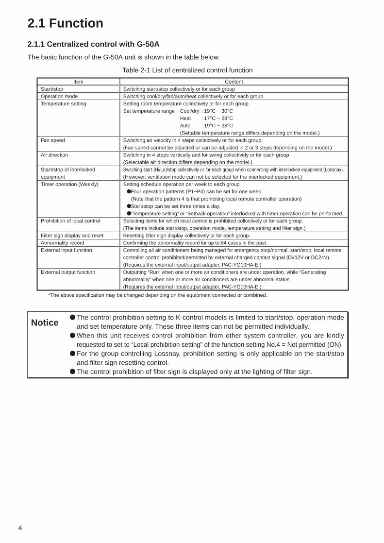
2.1 Function
2.1.1 Centralized control with G-50A
The basic function of the G-50A unit is shown in the table below.
Table 2-1 List of centralized control function
ItemStart/stopOperation modeTemperature setting
Fan speed
Air direction
Start/stop of interlocked equipmentTimer operation (Weekly)
Prohibition of local control
Filter sign display and resetAbnormality recordExternal input function
External output function
*The above specification may be changed depending on the equipment connected or combined.
ContentSwitching start/stop collectively or for each groupSwitching cool/dry/fan/auto/heat collectively or for each groupSetting room temperature collectively or for each groupSet temperature range Cool/dry : 19°C ~ 30°C
Heat : 17°C ~ 28°CAuto : 19°C ~ 28°C
(Settable temperature range differs depending on the model.)Switching air velocity in 4 steps collectively or for each group.(Fan speed cannot be adjusted or can be adjusted in 2 or 3 steps depending on the model.)Switching in 4 steps vertically and for swing collectively or for each group(Selectable air direction differs depending on the model.)Switching start (Hi/Lo)/stop collectively or for each group when connecting with interlocked equipment (Lossnay).(However, ventilation mode can not be selected for the interlocked equipment.)Setting schedule operation per week to each group.
●Four operation patterns (P1~P4) can be set for one week.(Note that the pattern 4 is that prohibiting local remote controller operation)
●Start/stop can be set three times a day.●“Temperature setting” or “Setback operation” interlocked with timer operation can be performed.
Selecting items for which local control is prohibited collectively or for each group.(The items include start/stop, operation mode, temperature setting and filter sign.)Resetting filter sign display collectively or for each group.Confirming the abnormality record for up to 64 cases in the past.Controlling all air conditioners being managed for emergency stop/normal, start/stop, local remote controller control prohibited/permitted by external charged contact signal (DV12V or DC24V).(Requires the external input/output adapter, PAC-YG10HA-E.)Outputting “Run” when one or more air conditioners are under operation, while “Generating abnormality” when one or more air conditioners are under abnormal status.(Requires the external input/output adapter, PAC-YG10HA-E.)
Notice● The control prohibition setting to K-control models is limited to start/stop, operation mode
and set temperature only. These three items can not be permitted individually.● When this unit receives control prohibition from other system controller, you are kindly
requested to set to “Local prohibition setting” of the function setting No.4 = Not permitted (ON).● For the group controlling Lossnay, prohibition setting is only applicable on the start/stop
and filter sign resetting control.● The control prohibition of filter sign is displayed only at the lighting of filter sign.

5
2.1.2 Centralized monitoring/controlling by Web browser
(1) Features
1 Without using a specific software, air conditioners can be controlled by your desk top PC by settingthe system (Web browser function is an optional and requires license registration).
2 On the one Web screen, operation status can be monitored in each G-50A unit (maximum 50 sets ofindoor unit).
3 In addition to the group control like G-50A, control of a block (consist of groups) can be performed.4 Annual schedule setting (Please refer to section 2.3 for function licence.) is possible.
(2) Function list
In addition to the centralized control with G-50A unit, controlling of a block can also be performed byusing the Web browser perusal software. The license registration required to use the various optionalfunction can be applied through this screen.
���
�����
��� ������ ����
�� �� ����������� �����
�� ��� ��� ����� ������� ������ !�������
"#����� $��� � �����% � ��� ��& ��� ���������
������� ������ ��� �� '������ ��� ��������
�� � ���� � �����( �� ������� ��)��������& ���
������*��+�� �������� ������� ��� ��� ��
����(
Figure 2-2 Outline diagram of Web browser system composition
Table 2-2 List of Web monitoring function
����
��������
������ ���
���������� ����� �
��� �������
��� �������
�������� � � ��������
������ � ���� ���
���� ��� � ���� � ���
!����� ��� ������ � � �����
"���� ��� ������
� ����#����� ��������
"���� ��� �$���� ������
%��� � �� ���������� ��� � ��� ��� ��� �� � ��� ������ � � ����� � �� � ��&
%��� ��� ����� � �� '� ������ � � ��� ���������� � ������� ���� ������� ��� � ����� ����� � ��&
%'����� ��� ����( ��� � �� � ��� � ��� ��� �� �� �� � ��� ������ �&
%������ ����� � ����� )(* �� �� ��� ���� ��&
+ �� �
�#����� � �������� ����������� � �� ���� ���
�#����� � ��������� ��������� ����������� � �� ���� ���
����� � �� ���������� ����������� � �� ���� ���
��� ���������� �� �� +����� - ./0+ 1 *20+
3��� - .40+ 1 )50+
��� - ./0+ 1 )50+
�#����� � ��� ������� � 6 ���� ����������� � �� ���� ���&
�#����� � � 6 ���� ���������� � � �� �#� � ����������� � �� ���� ���
�������� �� ��� ������� ������� ��� �� � ��� ����&�
�#����� � ����� �3������� ����������� � �� ���� ��� #�� � ���� � #��� � �������� ������ � ���� ���&
�3#����( �� ������ ��� �� � � �������� �� ��� � �������� ������ �&�
������� � ��� ����� �� #���� ���� � ��� �� ��� ���� ����������� � �� ���� ���&
������ � ����� ��������( ����� ���( ���������� ����� � � � ������ ��� &�
!����� ��� ������ �� � ����� � ���� ��� � �����������&
"���� ��� ������ �� � ����� � � 76 � �� �� � �� � �� � � ���� ����� ����&
8�� � ��� � ����#����� �������� �� ��� � ���� �� ���������� &
9$���� ������ �� � ����� � � 76 � �� ��&
Notice● The initial setting tool is required for the block set registration to monitor with Web
browser. Setting of abnormal mail transmission and gateway address should be madethrough the initial setting tool.

6
(3) Screen image
The screen images at Web monitoring are shown below.
Screen of air conditioner operation status(Batch display of all groups)
Control screen
Screen to set weekly schedule
Screen of air conditioner operation status(Display of each block)
Screen to display unit under abnormal state
Screen to set annual schedule

7
(4) Explanation of icons
The air conditioner icons on the Web screen are shown below.
(5) User setting1
When monitoring with the Web browser, 2 users can be set.As each user is given authority for each operation, the computer on the desk can be used as the localremote controller. Refer to 6.2.1 for detailed information.
(6) Remote monitoring
Connecting to the LAN where G-50A is installed through WAN or public line enables remote monitoringof air conditioners with the remote Web browser.
(7) Multilanguage display2
Monitoring can be conducted with languages other than English (French, German, Spanish, Italian,Russian, and Japanese) with the Web browser.The OS in the computer is automatically judged and the monitoring screen will be displayed in thenative language of the country. For example, when using English version Windows, English isdisplayed, when using French version Windows, French is displayed.
1 When using Personal Web function, use G-50A Ver.2.70 or later.2 When using Multilanguage display function, use G-50A Ver.2.70 or later.
ItemOperation status of air conditioner group
Operation status of ventilation equipment group (Lossnay)
Operation status of interlocked equipment
Schedule status
IconOperating
Operating
Interlocked ventilator operating
Schedule provided
Stopping
Stopping
Interlocked ventilator stopping
Schedule not provided
Energy-saving status
Abnormality generated
Abnormality generated
Filter sign generated
Filter sign generated
Controlling energy saving (operating) Controlling energy saving (stopping)

8
2.1.3 Centralized control by TG-2000A
(1) Features
1 The indoor unit up to 2,000 sets (40 sets of G-50A) can be controlled/monitored. 2 The layout display of air conditioners provides convenience in managing and controlling.3 Annual schedule can be set (requiring license registration in the optional function).4 Thanks to the apportioned function of electric power (requiring license registration in the optional
function), your PC may collect the electric power apportioned rate per indoor unit in CSV format.Then, you can calculate the air conditioning charge per group, block and area by inputting the WHMamount manually or summing up the value of WHM with the designated PLC (sequencer) andspecial program software (to count electric charge) or RS-485WHM.And also, electric (non Air conditioner), gas, water apportioned rate can be collected (In case of PLCand electric power apportioned rate software only).
5 Installing the exclusive software (for general equipment control) on PLC allows monitoring/operatingof the air conditioners and system equipment of other makes.
6 The energy consaving/peak-cut control function (optional function requiring license registrationseparately) can reduce the energy consumption of air conditioning equipment. By monitoring power consumption with PLC in addition, the peak-cut control corresponding to thepower consumption can be performed.
HUB
G-50A
Power supply unit
Watt Hour Meter (WHM) with pulse oscillation device
Install the integrated software (TG-2000A).
By installing the integrated software (TG-2000A) on the PC for centralized control, the operation status of all air conditioners being managed can be monitored and controlled.*1 Through the license registration in addition, the annual/weekly schedule function and electric power apportioning function can be used.
*1 Please refer to section 2,3 for function licence.
General equipment (Chiller, pump or the like)Monitoring, etc.
PLC (Counting power consumption)
PLC (Controlling general equipment)
Figure 2-3 Outline diagram of integrated soft system composition
1 The accounting block means a block for accounting configured by groups. As for details, refer to page 9.

9
(2) Caution against PC used with TG-2000A (Outline)
a) Items to be observed in selecting PC
b) Items to be observed in use
Please select a PC of desktop type.• Since a program is required to always be
operated under powered state depending on thefunctions to be used, it is recommended not toemploy a lap top type PC but employ a desktoptype PC. It is because the lap top type PC'stends to be filled with heat more easily than thedesk top type PC.
• Some lap top type models can not be operatedfor a long time.
Please prepare a PC/operating environment which allows TG-2000A to exhibit its function fully. • Use the OS with the specified operating environment. With other OS than specified, it is possible that
TG-2000A may not be operated.• Use a business model PC. In the case of the personal use model if employed, TG-2000A may not be
installed or trouble may be induced in its operation due to conflict with other application.
Recommend to install a UPS system on your PC.• In order to prevent your data from being
damaged or missed by instantaneous stoppingor failure of the power supply, it is recommendedto install a UPS (Uninterrupted Power Sourcesystem) on your PC.Especially when using the power apportionedcharging function, make sure to install the UPSwithout fail.
Do not place your PC unit in such places aslisted below.• Otherwise erroneous operation or malfunction
will be caused.A dusty place; a place where shock or vibrationis applied; a place with unstable foundation; aplace near heating equipment; a place nearstrong magnetic field like speakers; a placeexposed to direct sunlight for a long time; aplace where falling over is; a highly humidplace; a place with abrupt temperature change;a place where heat is stagnated
c) For others
Regarding PC and its peripheral equipment;• For the trouble with PC or its peripheral equipment, contact the maker. Please note that our company is
not responsible for such trouble.
Please do not clog the ventilation opening ofyour PC.• If clogged, the internal temperature will rise, and
a fire or machine trouble may be caused. Useyour PC under well ventilated condition.
Do not touch the ventilation opening of your PC.• As the temperature of exhaust air through the
ventilation opening is higher than the roomtemperature, a burn may be caused if touched.
When a lap top type PC is used, do not close its lid.• Otherwise, the internal temperature rises due to
the stagnated heat which may cause a fire,burning or machine trouble. Use the PC with thelid opened under well ventilated condition.
For the PC and its peripheral equipment, besure to read their installation manuals orinstruction manuals.• Erroneous handling may cause a fire or trouble
to the PC and its peripheral equipment.
Do not cover the PC unit or AC adapter orplace them near or on a heating instrument.• The internal temperature will rise possibly
causing a fire, burn or machine trouble.
When smoke, abnormal odor or sound isgenerated from the PC unit, or the unit isheated to such extent that you can not touch itdirectly with your hand, pull out the plug of thepower cord from the plug socket immediately.• Continuing to use under this state may cause a
fire, burning or electric shock. Consult yourdealer or PC maker in such case.
Please observe the caution on handling of thehard disk, floppy disk and CD media.• Do not give knock or vibration the hard disk,
floppy disk or CD under operation.• Do not turn the power source off or restart when
the hard disk, floppy disk or CD is operating.• Please do not move your PC when powered.

10
(3) Function list
By utilizing the software (TG-2000A) and collecting the data of each G-50A, the operation control can be performedfor up to 2000 indoor units in each floor or block on the PC screen.Please refer to section 2.3 for function licence.Additionally by using PLC (Programmable Logic Controller), general equipment can be controlled in addition to theelectric power apportioning function and energy saving control.
Table 2-3 List of integrated software
ItemStart/stopOperation modeTemperature setting
Air velocityAir direction
Start/stop of interlocked equipment (Lossnay)
Local control prohibition
Annual/weekly schedule
Power apportioned charging (Manual input of WHM amount)
Power apportioned charging(Pulse account)
Power apportioned charging (Direct collection of power consumption by PC)History record
Operation time monitoring
Masking of filter sign display
Defrost/Protection
Set temperature range limit
General purpose control function
Energy saving control
Peak cut control
ContentSwitching start/stop for whole building, or in each block, floor or groupSwitching cool/dry/fan/auto/heat for whole building, or in each block, floor or group.Setting room temperature for whole building, or in each block, floor or groupSet temperature range Cool/dry : 19°C ~ 30°C
Heat : 17°C ~ 28°CAuto : 19°C ~ 28°C
Switching air velocity in 4 steps for whole building, or in each block, floor or group.Switching in 4 steps vertically and for swing for whole building, or in each block, floor or group(Selectable air direction differs depending on the model.)Switching start (Hi/Lo)/stop for whole building, or in each block, floor or group when connecting with interlocked equipment (Lossnay). (However, ventilation mode can not be selected for interlocked equipment.)For whole building, or in each block, floor or group, items for which local control is prohibited can be selected. (The items include start/stop, operation mode, set temperature, filter sign reset.)License registration allows you to use the annual/weekly schedule function.Two seasonal setting (for summer and winter) can be used.Through the license registration of G-50A unit, the power apportioning rate data per indoor unit can be output in CSV format. Further by inputting the WHM amount manually, the power consumed by each tenant can be calculated easily.By registering license to G-50A, the air conditioning charge can be calculated through the apportioning of power consumption based on the air conditioner operating record per tenant by using PLC (Electric power counting software: PAC-YG11CDA) and WHM with pulse oscillation device. Through the registration of license number to G-50A unit, the power consumption of air conditioner by each tenant can be calculated by using RS-485 watt-hour meter (only for the designated models).The abnormal history record can be stored up to 3,000 and operation history record can be stored up to 10,000 respectively. The history record may be output as a daily and monthly record in CSV format.The integrated operation time of each indoor unit group*1 can be observed. It can be output as a file in CSV format. (This function is only effective when registering the charging function for license.)The automatic display of the filter sign may be suspended. (for a whole system collectively) In this case, the state of the filter sign can be checked by manual operation.With the schedule of each group, a temperature of 12 ~ 16˚C can be set under heating mode. However, only the M-NET indoor units are objected, while K-control and A-control indoor units are not objected. This function is effective only for ME remote controller system.It is possible to control the set temperature range from the remote controller or the browser screen of general users. The range limits include the lower limit value at cooling and the upper limit value at heating. This function is available only in the ME remote controller system. (PAR-F27MEA-E,F, PAC-SE51CRA-F)By installing the PLC software for general equipment to PLC, it is possible to schedule the operation and stop of other manufacturers’ air conditioners and facilities, and monitor them and monitor their error.By registering the license number to G-50A, energy saving control is available. By setting the control contents per block from TG-2000A, energy saving rotation operation is carried out in each group.By registering the license number to G-50A, energy saving peak cut operation is available according to the electricity use amount. This control requires PLC (electric power amount count software) separately, and by connecting an electric power meter, energy saving operation can be made according to the electricity use amount.
* The above functions are subject to change for improvement without notice.* The above functions are subject to change depending on the connected equipment or the combination of the equipment.
1 Operation time of minimum address unit is displayed in group.
Notice● The operation prohibition settings to K control type are only operation/stop, operation
mode, and temperature setting. Whether prohibition or permission on these 3 itemscannot be set individually.
● In the group controlling LOSSNAY, only operation/stop, and filter sign reset operation can beset for prohibition.
● Registration of the license number is carried out on each G-50A by the Web screen.

11
(4) Screen images
The screen images on the integrated software are shown as follows.
Screen to display each floor
Screen to display whole building
Screen to display all blocks
Control setting screen
Screen to set annual schedule
Screen to set weekly schedule

12
(5) Explanation of icons
The air conditioner icons on the TG-2000A screen are as shown below.Item
Operation status of air conditioner group
Operation status of ventilation equipment group (Lossnay)
Operation status of interlocked equipment Interlocked equipment operating
Schedule status
IconOperating
Operating
Interlocked equipment operating
With schedule
Stopping
Stopping
Interlocked equipment stopping
Without schedule
Operation prohibition status
Energy-saving status
Local remote controller control prohibited
Operation prohibited
Controlling energy saving (operating)
Controlling energy saving (stopping)
Others, system equipment status
Abnormality G-50A Abnormality K transmission converter
Abnormality outdoor unit Abnormality outdoor auxiliary unit
General equipment status Operating (monitor) Stopping (monitor)
With schedule Malfunction PLC
Operating (operation) General equipment error
Abnormality generated
Abnormality generated
Filter sign generated
Filter sign generated
Heat
The icon color can be changed with error monitoring.

13
2.1.4 Remote monitoring/controlling - Transmitting of abnormal mail
Remote controlling and monitoring can be performed from LAN, public telephone line and PHS if available.The control items are same as that of Web monitoring/controlling (except general equipment).Contracting with an internet provider can transmit an error code to the address designated by you at thegeneration of abnormality.
Notice ● The setting registration to transmit an error mail can only be made from the initial settingtool.
(6) Remote monitoring, wide area (multiple buildings) monitoring1
Connecting to the LAN where G-50A is installed through WAN2 or public line enables remote monitoringof air conditioners from TG-2000A.When monitoring multiple buildings with TG-2000, use wide area mode version TG-2000A. The displayof each building can be changed with simple operation and it is possible to monitor the operation statusof air conditioners which are installed in each building.When using the mail tool which is attached to wide area mode version TG-2000A, it is possible toconfirm a list of error mails on the screen which are received from the G-50A of multiple buildings.
Telephone line
ModemWide area mode
TG-2000A
Building CBuilding BBuilding A
Dial-up router Dial-up router Dial-up router
TG-2000A TG-2000A TG-2000A
TG-2000A
G-50A
G-50AG-50AG-50A
WAN
Figure 2-4 Wide area monitoring system example
*The automatic CSV output function and the trend data output function (refer to chapter 14.2) cannot beused with wide area mode version TG-2000A.
*When connected to the building (site), the time of the computer that is operated with wide area modeversion TG-2000A will be set to the time of G-50A to be connected. Confirm and adjust the time of G-50A regularly, so that the time can be set correctly. (Adjust the time between 8:00-21:45 at localtime.)
*When the local building (site) system has been changed, reflect the new system to wide area TG-2000A. When the system information does not match, the operation screen may not be displayednormally.
*Wide area mode version TG-2000A can control up to 40 G-50A units per one connection (site).
1 When monitoring wide area (multiple buildings), use wide area mode TG-2000 Ver.4.6.1 or later.2 Abbreviation for Wide Area Network. In wide area network, multiple LAN (Local Area Network) is connected each other with private lines.3 Refer to chapter 6.4 for setting method of error mail notification.

14
2.2 Comparison table of functionTable 2-4 compares the function of G-50A unit, Web browser and TG-2000A as follows.
Table 2-4 Function comparison table
Item
Start/stopOperation modeSet temperature
Set temperature range limiting functionAir velocity switchingAir direction switchingProhibition of local remote controller operationGroup registration
Filter sign
Abnormality of air conditioner
Schedule
Interlocked ventilationVentilation switchingMalfunction record
Operation recordIntegrated operation time*2
Electric power apportioning function*2
Energy saving/peak cut function
Content
Start/stopCool (Dry)/Heat/Fan/AutoSet temperature range (Unit 1°C)Cool (Dry) : 19°C ~ 30°CHeat : 17°C ~ 28°CAuto : 19°C ~ 28°CWith the local remote controller (ME remote controller), the lowest temperature is limited to that above 19°C at cooling (dry) and the highest temperature below 28°C at heating.Air velocity(Hi/Med. 1/Med. 2/Lo)Air direction: Vertical/swing/fixed louverProhibited items Start/stop, Operation mode, Set temperature, Filter resetting
Monitoring/displaying of filter sign, allowing reset operation after cleaning.Displays the condition of abnormality/normal of air conditioners, and allows to release the abnormality.[Weekly schedule]Set unit: 1 minute Daily operation frequency: 12 times Items: Start/stop, Operation
mode, Set temperature, Local control prohibition
[Annual schedule]Allows setting a special day for 50 times a year.[Daily schedule]Allows changing daily schedule only without changing weekly/annual schedules.[Weekly schedule]Set unit: 10 minute Daily operation frequency: 3 times Allows setting start/stop pattern for 3 times and permit/prohibition pattern for 1 time.Interlocked setting of indoor unit with ventilation equipment (Lossnay)Switching the stop/Lo/Hi of interlocked ventilation equipment (Lossnay).Observing malfunction history record about air conditioners.
Observing operation history record about air conditionersObserving integrated operation time per indoor unit.Allows printer and file outputting.Apportioning the electric power consumed by air conditioners based on the operation time of indoor /outdoor units.
Allows the air conditioner to control energy saving.
Controlling*7
: per unit :per group : per block : per G-50A :per floor : for whole building : Unable to comply with : Not providedMonitoring*7
G-50A
(Reset)
(Releasing abnormality)
(Switching)
Web browser
(Reset)
(Releasing abnormality)
(Switching)
TG-2000A
(Reset)
(Releasing abnormality)
(Switching)
(Charge block)
G-50A
(Grouping information
monitor)
(64 cases)
Web browser
(Grouping information
monitor)
(64 cases)
TG-2000A
(Grouping information
monitor)
(3000 cases) Allows outputting
CSV file.
(10,000 cases)*5
(Charge block)
*1 This is valid only when the week schedule/year schedule license is registered.*2 This is valid only when the charge license is registered.*3 Up to 64 error contents can be checked for unit errors and communication errors respectively.*4 Up to 3000 errors including errors (and others) detected by TG-2000A as well as unit errors and communication errors detected by G-
50A can be recorded. They can also be output in CSV format.*5 10000 cases of the contents operated from TG-2000A can be recorded.*6 Error release operation unit is as shown in the table, and all the erroneous units of G-50A system where error release operation is made
are released.*7 Please refer to section 2.3 for function licence.*8 The settable unit (indoor unit or outdoor unit) differs depending on the controlling content.
*6 *6 *6
*4*3
*8
(Setting)

15
2.3 Products listThe functions to be coped with by G-50A, and necessary components, software and so forth are listed inTable 2-5.
Table 2-5 Products list
Table 2-6 Function and license list
Name
Centralized control Web monitoringPersonal webRemote monitoring/operationAnnual/weekly scheduleSimplified division accounting Full division accounting*13
Meter accounting(direct reading charging)General purpose device controlSaving energy controlPeak cut control (Electric energy monitor method)Peak cut control (Demand controller method)
Centralized controller
Transmission line power supply unit
TG-2000ASoftware
Electric Amount Count Software
PLC Software for General Equipment
License registration PLC
Contract with
providerOther
System component Others
PLC methodRS-485 method
*1
*6
*10
*10
*11
*10
*2
*3
*4
*5
*8
*9
*9
*12
*7
PLC Software for Demand
Input
*1 It is possible to use the Annual/Weekly schedule function without TG-2000A. However, part of functions are not available. As for details,refer to “Step 4 : Conduct of Annual/Weekly Schedule” section.
*2 The Annual/Weekly Schedule license is required.*3 The Charge license is required.*4 The Charge license is required.*5 The Charge license is required.*6 The control on only general purpose devices is not applied at present. It is necessary to connect G-50A without fail.*7 Other sequencer (PLC) than the pulse count software is required.*8 The Saving Energy Control license is required.*9 The Saving Energy Control (Peak Cut) license is required.*10 The Web Monitor license is required.*11 The Personal and Web Monitor license is required.*12 RS-485WHM, and converters such as RS-232C, RS-485 or the like are required.*13 Only either PLC type or RS-485WHM type can be used.
Necessary license
Function to be usedWeb browser (Web for administrators)Personal Web (Web for public users)Error mail notificationAnnual/Weekly scheduleMonitoring/operation of air conditionersAnnual/Weekly schedulePower apportioning chargingAir conditioner operation time accumulationSaving Energy ControlSaving Energy Control & Peak CutMonitoring/operation of general equipments (Ver. 1 series)Monitoring/operation of general equipments (Ver. 2 series)Maintenance tool (Ver. 4.02 -)Maintenance tool simplified version (Ver. 4.02D -)
BACnet InterfaceSoftware
Web Monitor
ChargeAnnual ScheduleWeekly Schedule
SendingError Mail
Saving Energy Control
Saving Energy Control
(Peak Cut)
Personal Web
PLC for General
Equipments
Maintenance Tool
Advanced
Maintenance Tool BACnet
G-5
0AM
aint
enan
ce to
olBA
Cnet
TG
-200
0A

16
2.4 Specification
2.4.1 Centralized controller: G-50A
ItemDimensionsWeightPower source
Power consumptionEnvironmental conditionMaterialExternal color
Installation environment
Detail120 (H) × 300 (W) × 80 (19)(D) mm1.0kg / 2 1/4 lbDC24V, 0.02A (Maximum loading)Power received from PAC-SC50KUA Power Supply Unit via M-NET transmission line.DC12V, 0.2A (Maximum loading)Power received from PAC-SC50KUA Power Supply Unit via the DC power line.0.2ATemperature: 0 to 40°C / 32 to 104°F Humidity: 30 ~ 90%RH (No condensation allowed)ABSCover section: White gray(MUNSELL 4.48Y7.92/0.66)Liquid crystal surrounding section: Medium gray (DIC551)Mount to a electric box.Connect the M-NET transmission line (centralized control line which is connected to TB7 of the outdoor unit) to M-NET transmission line terminal A and B. (Non Polarity)Connect the DC power line from the power supply unit (PAC-SC50KUA) to the DC power supply terminal block of this device.There is a 12VDC and a GND polarity.
300
220
280
91 47
RS-232C
Detailed switch section
LAN
46 34
22 57
120
70
21
83.513
28
25ON/OFF
12VDCGND
CENTRAL CONTROLLERG-50A
TEMP.
ON/OFFMODE
FAN SPEED
RESETPROHIBITIONREMOTE
MODETIMER
AIR
DIRECTION
VENTILATION
CLOCK/PATTERN
TEST RUN
NumberFile Text
0011 2 3
4 5 6
7 8 9
0 DEL.
INS.
GROUPSELECT
SCREENBACK
ENTER
2.4.2 Power supply unit: PAC-SC50KUAItem
Source power requirement
Output voltage/currentLoad capacityEnvironmental condition
DimensionsWeightInstallation environment
Detail
Fuse: 2.0A Time-delay type (IEC127-2 S.S.5)M-NET : DC24V 0.45A (Maximum loading)DC power supply: DC12V 0.2A (Maximum loading)Number of the loading unit: G-50A Central Controller 1 unit
240(H) × 265(W) × 59.2(D) mm/9 1/2(H) × 10 7/16(W) ×2 3/8(D) in2.3kg / 5 1/8 lbIn the control panel box (indoor)*This unit is installed and used in a business office or equivalent environment.
EU: ~ 220V - 240V; 0.25A/50Hz Single-phaseUS: ~ 208V - 230V; 0.25A/60Hz Single-phase
Rated inputvoltage and current
Operating range 0 to 40˚C/32 to 104˚FStorage range –20 to 60˚C/–4 to 140˚F30 ~ 90%RH (No condensation)
Temperature
Humidity
265 (10 7/16) 59.2 (2 3/8)150 (5 15/16)
TB3
TB2
unit: mm (in)
UP
EU:~220V-240V; 0.25A 50HzUS:~208V-230V; 0.25A 60Hz
2.3 kg / 5 1/8 lb
Cable fixtureCable fixtureTB1
225
(8 7
/8)
240
(9 1
/2)
1 Refer to chapter 5.1.2 and 5.1.3 for power supply.

17
Step-1: Selection of air conditioning equipment (Objective equipment for control, limitations and the like)
Step-2: Selection of system control parts (Quantity of G-50A and other system controllers)
Step-3: Construction of G-50A system (Limitation on LAN wiring and the like)
Step 4: Optional function (With weekly/annual schedule employed)
Step 5: Optional function (With electric power apportioned charging)
Step 6: Optional functions (energy saving function, peak cut function)
System 1: With centralized control by PC employed (Connection of plural G-50A unit)
System 1: Applied weekly/annual schedule by integrated software
System 2: Applied weekly/annual schedule by Web monitoring
System 3: Annual schedule not applied
Step 7: Selection of measuring instruments
Step 8: General purpose equipment control
Step 9: Determining number of PLC units
Step 10: Determination of address for air conditioning equipment and PC for control
Step 11: Confirmation of other functions
System 1: Energy saving control System 2: Peak cut control System 3: Not applied
System 1: Electric power pulse counting
System 2: Electric power manual inputting
System 3: Measuring instrument(Direct reading method)
System 4: Electric power count by PC direct connect (Watt Hour Meter (RS-485))
System 2: Without centralized control by PC employed
3. System Design FlowThe design flow to construct the G-50A system is given below.

18
4. Step 1: Selection of Air Conditioning EquipmentIn order to construct the system, air conditioning equipment should be selected firstly. This chapter introduces the air conditioners that can be controlled with G-50A and various limitationsapplicable. For the detail of air conditioning equipment, please refer to the manual of the relating airconditioner.
4.1 Limitations
4.1.1 Limitations on system composition
Table 4-1 Limitations on system compositionItem
Controllable indoor unit quantity with 1 set of G-50AConnecting quantity of G-50A
Controlling quantity of integrated software
Detail1 set of G-50A can control indoor unit up to 50 sets. Lossnay if connected should be included in this figure.As G-50A will be the upper system controller inside a centralized system, the quantity of G-50A connectable with the centralized system counts for 1 set only.The quantity of G-50A that can be controlled with the integrated software is 40 sets. This can be converted into air conditioner indoor unit of 2000 sets maximum.
Limitation50 sets
1 set
40 sets of G-50A
4.2 Control objective devices
4.1.2 Limitation on group setting
Table 4-2 Limitation on group settingItem
Connectable remote controller within 1 groupConnectable indoor unit within 1 group
Registration of system controller and remote controller within 1 groupGroups on 1 floor
DetailFor the MA remote controllers, group setting is not necessary for G-50A. (ME and MA remote controllers can not be used together within a same group.)The indoor unit, K-control indoor unit, A-control indoor unit and Lossnay can not be grouped.The setting that runs over G-50A can not be applied.Not including the quantity of G-50A
On the screen of whole building display, 50 groups maximum can be configured and displayed per floor. (At displaying of floor screen, it may not be displayed due to the floor diagram.)
LimitationUp to 2 sets
Up to 16 sets
Up to 4 sets
Up to 50 groups
Table 4-3 Control objective devices
FunctionType
Monitoring/operationPower apportioning
charging (without electric meter)
Power apportioning charging
(with electric meter)
Energy saving/ peak cut
Night mode setting
City Multi (free plan non heat reservation type)
LOSSNAY
Others
City Multi YCity Multi Super YCity Multi R2City Multi WR2City Multi WYCity Multi S
Free plan LOSSNAYLOSSNAY with heating and moisteningK control type
A control slim typeRoom air conditioner
*1 An adaptor is required separately. A control slim type: M-NET connection adaptor, K control type: K transfer converter, Room air conditioner: M-NET control interface.*2 The indoor units before free plan are not applied for Power apportioning charging. (They are according to electricity amount
pulse count method (direct reading method).) Free plan indoor unit : P*FY model, before free plan indoor unit : P*RY model and older.*3 M-NET model outdoor unit YMF-B type or later is applied. *4 This can be applied in the case of use by WHM.*5 Application by FAN operation is possible.*6 Performance save control to outdoor units are not available.*7 Thermo OFF control to indoor units is not available, therefore FAN operation control is carried out.*8 In the case of use by IC properties, energy saving control similar to free plan indoor units can be carried out. With FU properties, same control as free plan LOSSNAY is available.*9 Only the stop control is valid.
*2
*2
*2
*4
*4
*4
*4
*6
*9
*8
*7
*6
*1
*1
*5
*5
*5
*5
*3

19
4.3 The Combination of TG-2000A and G-50A
TG-2000AG-50A
TG-2000 function overview
Electricity apportioning charge (hand input of electricity amount, RS-485 WHM method)Electricity apportioning charge(Pulse count)Energy saving/peak cutSet temperature range limit (for the ME remote controller)Electricity apportioning charge (gas and water line)General equipment monitoring operationTrend functionAuto-change overNight mode schedulePeak cut (for demand input PLC)General equipment control (for schedule and free contact)Wide area (multiple buildings) monitoringSet temperature range limit (for ME compact remote controller)
Ver.1.03~Ver.2.30 Ver.2.31 Ver.2.50 Ver.2.51 Ver.2.60 Ver.2.70 Ver.2.71
Ver.2.00 ~
Ver.4.10 ~
Ver.4.30 ~
Ver.4.40 ~
Ver.4.50 ~
Ver.4.60 ~Ver.4.70 ~
*1 The functions which are shown in the “TG-2000A function overview” table above cannot be used with the G-50A whose version is (0).
*2 When apportioning the electricity charge, use G-50A Ver.2.31 or later.*3 When G-50A Ver.2.50 or later is used, TG-2000A Ver.2.00 cannot be used.*4 When using the control function for the general equipment, use G-50A Ver.2.70 or later.*5 The trend function can be used with G-50A Ver.2.31 or later.
*4
*2*3
*5*1
*5
( )
( )
( )
( )
( )
( )
( ) ( )
( )
( )
( )
( ) ( ) ( ) ( )
( )
( ) ( )

20
4.4 Limitation on transmission line wiringThe material and wiring limitation of transmission line and signal line are given in Table 4-4.For the detail of the limitation on each wiring length, please refer to Items 4.4.1.
4.4.1 M-NET transmission line
Figure 4-1 shows the wiring example of M-NET bus. When the centralized control system M-NET bus and indoor-outdoor transmission M-NET bus per onesystem are shown in relation with the wiring length limitation, the total wiring length in the followingexample can be expressed by the following equation.This represents the distance limitation to perform proper communication with other equipment on M-NETbus. If this distance is exceeded, M-NET signal can not reach the end equipment thus making thecommunication and control impossible.
a+b+d+e(f) 500m a+b+c+g 500m e(f)+d+c+g 500mThe local remote controller wiring length counts for 10m or less. When it exceeds 10m, add the exceededlength to the value of “total wiring length 500m or less.”
Table 4-4 Materials used for transmission/signal lines and limitation of wiring lengthTransmission route
Centralized control system M-NET busIndoor-outdoor transmission system M-NET bus
Indoor-outdoor connecting line of A-control Slim air conditioner
K-control transmission line
Wire typeCVVS1.25mm2-2C or CPEVS�1.2-1PCVVS1.25mm2-2C or CPEVS�1.2-1PIn case when the wiring length of cable connecting to local remote controller is less than 10m, use 2-core cable of 0.3 ~ 1.25mm2 (recommend to use 0.75mm2 or less for wiring convenience). When it exceeds 10m, use CVVS1.25mm2-2C or CPEVS�1.2-1P for the exceeded portion.VVF�1.6 -3CFor the cable connecting with local remote controller, use the optional remote controller cable (wire length of 10m ~ 20m) or 2-core cable of 0.3 ~ 1.25mm2.2-core cable of �1.6 or moreWire type: Use any of VCTF, VCTFK, CVV, CVS, VVR, VVF or VCT. When the cable connecting to local remote controller is less than 12m, use 2-core cable of 0.5 ~ 0.75mm2, while when it exceeds 12m, use the above cable for the exceeded portion.
Limitation on wire lengthTotal wiring length: 500m or lessCentralized control system M-NET bus (Power supply distance): 200m or lessIndoor-outdoor transmission line M-NET bus (Power supply distance): 200m or lessRemote controller wiring: 10m or lessTotal wiring length: 50m or lessRemote controller wiring length: 10m or less(Extendable up to 200m)Total wiring length in case of K-control model 20 sets and local remote controller of 10 sets or less: 500m or lessK-control model 50 sets and local remote controller of 25 sets or less: 200m or lessOther than above: Requires relay board.Remote controller wiring: 12m or less
Centralized control system M-NET bus
DC12V (max 10m)
b
a
c
g
f
10m
d eIndoor-outdoor transmission system M-NET bus
Centralized controller (G-50A)
Power supply unit(PAC-SC50KUA)
Indoor unit
Indoor unit Indoor unit
Indoor unit
Indoor unit
Localremote
controller
Outdoor unit
Outdoor unit
Figure 4-1 M-NET bus wiring diagram
21
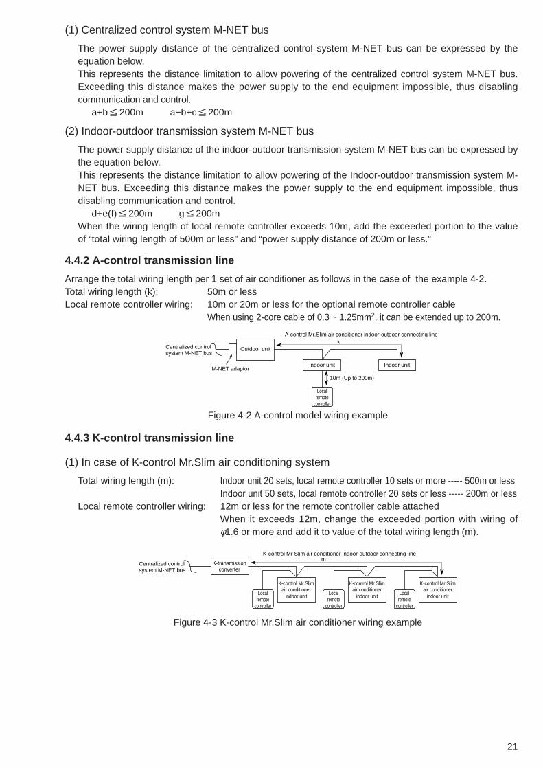
(1) Centralized control system M-NET bus
The power supply distance of the centralized control system M-NET bus can be expressed by theequation below.This represents the distance limitation to allow powering of the centralized control system M-NET bus.Exceeding this distance makes the power supply to the end equipment impossible, thus disablingcommunication and control.
a+b 200m a+b+c 200m
(2) Indoor-outdoor transmission system M-NET bus
The power supply distance of the indoor-outdoor transmission system M-NET bus can be expressed bythe equation below.This represents the distance limitation to allow powering of the Indoor-outdoor transmission system M-NET bus. Exceeding this distance makes the power supply to the end equipment impossible, thusdisabling communication and control.
d+e(f) 200m g 200mWhen the wiring length of local remote controller exceeds 10m, add the exceeded portion to the valueof “total wiring length of 500m or less” and “power supply distance of 200m or less.”
4.4.2 A-control transmission line
Arrange the total wiring length per 1 set of air conditioner as follows in the case of the example 4-2.Total wiring length (k): 50m or lessLocal remote controller wiring: 10m or 20m or less for the optional remote controller cable
When using 2-core cable of 0.3 ~ 1.25mm2, it can be extended up to 200m.
4.4.3 K-control transmission line
(1) In case of K-control Mr.Slim air conditioning system
Total wiring length (m): Indoor unit 20 sets, local remote controller 10 sets or more ----- 500m or lessIndoor unit 50 sets, local remote controller 20 sets or less ----- 200m or less
Local remote controller wiring: 12m or less for the remote controller cable attachedWhen it exceeds 12m, change the exceeded portion with wiring ofφ1.6 or more and add it to value of the total wiring length (m).
Figure 4-2 A-control model wiring example
Centralized control system M-NET bus
M-NET adaptor
A-control Mr.Slim air conditioner indoor-outdoor connecting line
10m (Up to 200m)
Outdoor unit
Indoor unit
Local remote
controller
Indoor unit
k
Figure 4-3 K-control Mr.Slim air conditioner wiring example
Centralized control system M-NET bus
K-control Mr Slim air conditioner indoor-outdoor connecting line
K-transmission converter
K-control Mr Slim air conditioner
indoor unit
K-control Mr Slim air conditioner
indoor unit
K-control Mr Slim air conditioner
indoor unitLocal remote
controller
Local remote
controller
Local remote
controller
m

22
[Example to use relay board]
(2) In case of K-control Y-series system
Total wiring length (p): 500m or less, when exceeded this length, be sure to use the relay board.
Figure 4-4 Relay board wiring example
Centralized control system M-NET bus
K-control Mr.Slim air conditioner
indoor unit
K-transmission converter
Relay board Relay board
Local remote
controller
K-control Mr.Slim air conditioner
indoor unitLocal remote
controller
K-control Mr.Slim air conditioner
indoor unitLocal remote
controller
K-control Mr.Slim air conditioner
indoor unitLocal remote
controller
m
m m
Figure 4-5 K-control Y-series wiring example
Centralized control system M-NET bus
K-control Y-series
indoor unit
K-transmission converter
K-control Y-series
outdoor unit
K-control Y-series
outdoor unit
Local remote
controller
K-control Y-series
indoor unitLocal remote
controller
K-control Y-series
indoor unitLocal remote
controller
p
(3) In case of system where K-control Mr.Slim air conditioner and Y-series are mixed
Be sure to use the relay board as shown in the figure below, and connect the indoor unit of K-controlMr.Slim air conditioner to the secondary side of the relay board.
Figure 4-6 K-control mixing system example
Centralized control system M-NET bus
K-control Mr.Slim air conditioner
indoor unit
K-controlY-series
outdoor unit
K-transmission converter
Relay board
Local remote
controller
K-control Mr.Slim air conditioner
indoor unitLocal remote
controller
K-controlY-series
indoor unitLocal remote
controller
p
[Caution for wiring connection work]● The wiring connection work of the equipment delivered (MELANS equipment, air
conditioning equipment, etc.) including power and earth lines.● Install the transmission line and signal line apart from the power line and earth
line. If not, the noise from the power/earth lines will mix into the transmission lineor signal line causing to generate erroneous operation.
● In case of shielded line, provide one-point grounding at each transmission line.(Relay shielded line at the terminal block of each equipment.)
CAUTION

23
5. Step 2: Selecting System Management Parts5.1 M-NET system structureThere are cases in which other System Controllers (SC) besides model G-50A can be run on the G-50Asystem structure.In order to do so, the following outlines a number of rules to be observed for system management.
Figure 5-1 System controller concept
Disable the prohibit remote controller setting
G-50A
System remote controller
Main SC
Sub SCSC setting the prohibition remote controller operation
Power supply unit (PAC-SC50KUA)
5.1.1 Concept of the system controller
The G-50A is always the host system of a self-controlling system structure.In addition, for a SC enabling the setting to permit prohibition of the local remote controller operation,please set up the system in such a way the setting is done with 1 SC unit for the remote controller inquestion.
(1) Main system controller and sub system controller
When an air conditioning system is supposed, the system controller (SC) to control the entire operationsystem connection information is positioned as the main SC. While, the sub SC means the SC tocontrol air conditioners by receiving the operation system connection information from the main SC.Therefore, the initial settings including group setting and so forth may be made basically only on themain SC, and there is no need to carry out the group setting on the sub SC.Priority of the main SC is determined according to the functions of the SC (the number of units tocontrol, the number of groups to control, etc.).G-50A is the most multifunctional type in the system, accordingly it always becomes the main SC.
(Main SC priority)G-50A > PAC-SF44SRA > PAC-YT34STA > PAC-YT40ANRA > PAC-SC30GRA > PAC-YV02LMAP
(2) SC setting the prohibition remote controller operation
This SC can prohibit the operation of remote controller.The number of “SC setting the prohibition of remote controller operation” must be one for each remotecontroller.Normally, in the G-50A system, the G-50A is the SC setting the prohibition of remote controlleroperation. However, in the case you want to disable operation of the remote controller using another SC(sub SC), please select “Disable the setting from this unit to prohibit remote control” during initial setupof G-50A. (Refer to following figure).For details, please refer to the operation manuals of each SC.

24
Figure 5-2 Transmission line supply classification
Power supply unit
G-50A
DC12V
M-NET modelCentralized transmission line
K-control centralized transmission line
Indoor/outdoor transmission line
Extended transmission lineA-control type
K-control model
Relay port
K-transmission converter
DC12V
Power supply unit
Power supply unit
OA Processing unit(SW3-1 to ON)
PAC-SF46EPA
G-50A
Lossnay remote control
Group 1 Group 3
Lossnay Lossnay
Group 4
5.1.2 Regarding power supply within the system
(1) Regarding power supply parts
Within the G-50A system, the parts serving to supply electricity are fixed for each transmission line.Please take care there is duplicate any one transmission line.Centralized control transmission line : supplied by transmission line supply unitIndoor/outdoor transmission line : supplied by outdoor unitK-control centralized transmission line : supplied by K-transmission converter (KA)Extended transmission line : supplied by relay port
Only for the Lossnay system, please use the power supply unit (PAC-SC50KUA, PAC-SF46EPA).
Figure 5-3 Electricity supply using a Lossnay system
(2) Definition of the supply connector in the outdoor unit
In the outdoor unit, the power supply to the centralized control transmission line is determined by wherethe supply connector is packaged.
Electric power supply
Centralized control transmission line
Regular electric power supply
Indoor/outdoor transmission line
TB7 TB3 No electricity supply
Centralized control transmission line
Regular electric power supply
Indoor/outdoor transmission line
TB7 TB3
When inserting the CN-40
*K-control outdoor unit Factory shipping condition *M-NET outdoor unit Factory shipping condition
When inserting the CN-41

25
5.1.3 Selecting a power supply unit
G-50A operates on a DC12V current, and it requires power feeding of an M-NET transmission line in orderto communicate with the air conditioners.
Figure 5-4 Connection of centralized control transmission line (PAC-SC50KUA power supply)
Although Lossnay can be connected, there is a restriction on the number of connectable.
TB3(DC12V)TB2
(M-NET)
Main SC
Sub SC
Transmission linebooster unit
(PAC-SF46EPA)
No. 000 unit
No.201 unit
Lossnay Lossnay Lossnay
Power supply unitPAC-SC50KUA
Centralized control transmission line Indoor/outdoor transmission line
Indoor/outdoor transmission line
(1) Connecting to the centralized control transmission line
(1-1) Supplying power from the power supply unit PAC-SC50KUA
Central controller(G-50A)
Other system controllers Remote controllers
ON/OFF remote controller (AN)System remote controller (SR)Schedule timer (ST)Group remote controller (GR)
6 units 12 units
ME remote controllerLOSSNAY remote controller
24 units2 units (Note 1)
If the number of connected units exceeds the limit, use a power supply extension unit for transmissionlines (PAC-SF46EPA). When PAC-SF46EPA is connected, controllers for 50 remote controllers (12.5[Power consumption unit]) can be added.
(Note 1)The number of connectable G-50A units is 2 due to the power supply capacity of DC12V.2 cantral controllers (G-50A) mey be connected when system is divided.
Central controller(G-50A)
Other system controllers Remote controllers
ON/OFF remote controller (AN)System remote controller (SR)Schedule timer (ST)Group remote controller (GR)
1 0.5
ME remote controllerLOSSNAY remote controller
0.250.5
Table 5-1 Power consumption unit for each controller
Power consumption unit ratio for each controller when power consumption of indoor unit control board is setto one unit is shown in the table below.
As the power supply unit PAC-SC50KUA can supply 6 power consumption units at maximum, the maximumnumber of connectable units is shown below.In this case, leave the power supply switch connector CN41 on the outdoor unit as it is (factory setting).
Table 5-2 Maximum number of connectable units for each controller (with the use of PAC-SC50KUA)

26
0
1
2
3
4
5
6
7
8
9
10
11
12
0 1 2 3 4 5
- V V V V
V V V V V
V
V
V V
V V
V V V
V V V
V V V V
V V V V
V V V V V
V V V V V
V
V : Connectable
V
6
System remote controller (SR)Schedule timer (ST)Group remote controller (GR)
Total number of
Total number of ON/OFF remote controller (AN)
Refer to the following table for the number of connectable system controllers when connecting one G-50Aunit.
● When using optional functions of G-50A, such as “Charge” or “Peak cut”, powershould be supplied not from the outdoor unit but from the Power Supply Unit(PAC-SC50KUA). Power off of the outdoor unit disables the transmission, aspower supply to the transmission line stops. Even if other outdoor units areoperating, collection of charging data and peakcut control cannot be conducted.
CAUTION
Table 5-3 Number of connectable units for each controller

27
Figure 5-5 Centralized control transmission line (powered from the outdoor unit and DC12V power supply)
Power supply unit(DC12V 0.2A)
Centralized control transmission line Indoor/outdoor transmission line
Indoor/outdoor transmission line
R410AOutdoor unit
Replacement of CN41 with CN40
Use CN41 as it is
(1-2) Supplying power from R410A outdoor unit and from DC12V power supply
When using R410A outdoor unit, replacing the power supply switch connector (CN41) with CN40 enables to supply power to the centralized transmission line. Power of G-50A can be supplied with commercially available DC12V power supply.
Use only DC12V that meets the following specification, and the connection distance between G-50A mustbe 10m or shorter.
Moreover, when connecting the system controller to which the power is supplied from the outdoor unit, thenumber of refrigerant indoor units, which can be connected, will decrease as shown in the table below.
Central controller(G-50A)
Other system controllers
ON/OFF remote controller (AN)
System remote controller (SR)Schedule timer (ST)Group remote controller (GR)
1 0.50.5
Indoor unitcontrol board
1
Table 5-4 DV12V power supply specification
Source power
Ripple noise
Compatible specification
Use the items that are certified by the third party organization or CE marking.The compatible specifications are as follows. IEC60950 (or EN60950) CISPR22/24 (or EN55022/24) IEC61000-3-2/3-3 (or EN61000-3-2/3/3)
DC12V 0.2A (Maximum loading)
150mVp-p or less
● We assume no responsibility whatsoever for any damages or anyhazards resulting from the use of commercially available DC12V powersupply.
● When using optional functions of G-50A, such as “Charge” or “Peakcut”, power should be supplied not from the outdoor unit but from thePower Supply Unit (PAC-SC50KUA). Power off of the outdoor unitdisables the transmission, as power supply to the transmission linestops. Even if other outdoor units are operating, collection of chargingdata and peak cut control cannot be conducted.
● When the outdoor unit malfunctions, replacing the power supply switchconnector (CN40) of the faulty unit with CN41, and replacing the powersupply switch connector (CN41) of other outdoor units with CN40enable transmission recovery.
CAUTION
Table 5-5 Power consumption unit for each controller
For example, when the outdoor unit, which can connect up to 16 indoor units, is used, or when one 0.5-[Power consumption unit] system controller is connected, the number of connectable indoor units is16units-1unit (0.5unit round up) =15units.

28
(2) Connecting to the indoor/outdoor transmission line
When a G-50A is connected to the indoor/outdoor transmission line, only terminal used is the DC12Voutput terminal (TB3) of the PAC-SC50KUA, which supplies DC12V current to the G-50A.Connect the indoor/outdoor transmission line to the M-NET terminal of the G-50A.*The M-NET terminal (TB2) on PAC-SC50KUA is not used; do not connect any M-NET line to it.*To use the system without the power supply unit PAC-SC50KUA, use the commercially available DC12V power supply to supply power of G-50A.In this case, use only DC12V power supply that meets the specification as shown in the table 5-4, andthe connection distance between G-50A must be 10m or shorter.
When connecting G-50A or system controllers to indoor/outdoor transmission line, the number of theindoor units, which can be connected to the outdoor units in the refrigerant system, will decrease asshown in the table below.
Figure 5-6 Indoor/outdoor transmission line connections
When connected to the indoor/outdoor transmission line, only the DC12V output(TB3) on PAC-SC50KUA will be connected to G-50A. The indoor/outdoortransmission line will be connected to the M-NET terminal of the G-50A. M-NET line must not be connected to the M-NET terminal (TB2) of PAC-SC50KUA. The maximum allowable length of DC12V wiring is 10 m.
PUHY-P250YEM-AM-NET model
The number of connectable unit decreases.
001 002
G-50A
010 011 012 013 014 015 016
TB3(DC12V)
TB2(M-NET)
Power supply unitPAC-SC50KUA
(Example: Y Series (PUHY-P250YEM-A)The number of indoor units that can be connected to an outdoor unit is 16. If one system controller(such as G-50A) is connected to the indoor/outdoor transmission line in this system, the number ofconnectable indoor units will be calculated as the following: 16 units – 1 unit (round up 0.5 unit) = 15 units
Central controller(G-50A)
Other system controllers
ON/OFF remote controller (AN)
System remote controller (SR)Schedule timer (ST)Group remote controller (GR)
1 0.50.5
Indoor unitcontrol board
1
*In order to secure transmission quality during the start-up of outdoor unit (during traffic), the number of system controllers, which can be connected to indoor/outdoor transmission line in the same system, is up to three.
● We assume no responsibility whatsoever for any damages or anyhazards resulting from the use of commercially available DC12V powersupply.
● When using optional functions of G-50A, such as “Charge” or “Peakcut”, power should be supplied not from the outdoor unit but from thePower Supply Unit (PAC-SC50KUA). Power off of the outdoor unitdisables the transmission, as power supply to the transmission linestops. Even if other outdoor units are operating, collection of chargingdata and peak cut control cannot be conducted.
CAUTION
Table 5-6 Power consumption unit for each controller

29
5.1.4 When managing a K-control model
When managing a K-control type device, a separate K- transmission converter, model PAC-SC25KAA, is required.
(1) System controllers able to control a K-control type device
A K- transmission converter unit only accepts communication with a upper controller with bearingaddress [000].Consequently, since the G-50A is fixed (address [000]) as the upper controller, even if multiple systemcontrollers are included in a single system, control of K-control type devices is only conducted using the G-50A.
G-50A
Systemremote control
Transmissionenabled
M-NET transmission line K-control transmission line
K-control model
Transmissiondisabled
K- transmission converter
220
Figure 5-7 Management of K-control models
Figure 5-8 K-control converter address
Power supply unit
M-NET type device
K-control models
001 002
011 012
020
+200
021
G-50A
K- transmission converter: 220
5.1.5 Synchronized settings
The Lossnay with built-in heater and humidifier and which has been set for synchronization starts and stopsoperation synchronized with an indoor unit that has been set for synchronization. Furthermore, it is alsopossible to operate the Lossnay or the OA Processing unit independently using the ME remote controller thatcontrols the indoor unit in question. Synchronized operation of two or more OA Processing units in addition toa Lossnay unit using one indoor unit is impossible.
(2) Concerning the address of the K- transmission converter (PAC-SC25KAA)
The address of the K- transmission converter is [200 + the smallest address of the K- models].The address of the K- transmission converter expresses the borderline of the M-NET type device andthe K-control models. As a case example, in the case the number of G-50A units is 38 units and the address of the Ktransmission converter is [220], the addresses from [20] on and after are all interpreted as K-controltype devices and are started up according to K-control.In other words, care has to be taken the addresses of K-control models are set after those of the addressesof the M-NET type devices, while fitting addresses should be set for the K -transmission converter.
● OA Processing unit can be controlled as an indoor unit by setting the DIPswitches. In the case of OA Processing unit is to be controlled as an indoor unit,please set DIP switch 3-1 of the OA Processing unit to ON.
● Synchronized operation of two or more Lossnay units with built-in heater andhumidifier in addition to a Lossnay unit using one indoor unit is impossible. Withone OA Processing unit, synchronized registration of maximum 16 indoor unitscan be performed.
CAUTION

30
Optional: PAC-YG10HA-E
12VDC GND
5.2 External input/outputThe main unit of the G-50A is equipped with an external input/output function. This function enablesexternal input control and output monitoring for each G-50A unit.This function uses the main unit of the G-50A’s CN2. For use, please purchase the optional externalinput/output adapter (PAC-YG10HA-E).
5.2.1 External output signal function
(1) External input
Using the external signal indicating contact point voltage (DC 12V or DC 24V) all air conditioning unitsmanaged, can be controlled for emergency stop/regular start/stop and for prohibition/permission forlocal remote controller operation.Switching of each input mode can be set from the main unit of the G-50A or by using the initial settingtool. (Default value: not used)
Table 5-2 External input function table
No.
12
3
4
Function of the external input signal
Do not use the external input signalEmergency stop/regular (level signal)
Start/stop (level signal)
Start/stop and prohibition/permission (pulse signal)
Remarks
None (factory shipping condition)An emergency stop signal will stop the operation of all air conditioning units while disabling the prohibition/permission operation from the local remote controller, the start/stop operation on the main unit, and the prohibition/permission change operation.Disables the prohibition/permission operation from the local remote controller, the start/stop operation on the main unit, and the prohibition/permission change operation.Please set the pulse length during contact point ON to 0.5 - 1 second.
Function selection switchNo. 6OFFOFF
ON
ON
No. 7OFFON
OFF
ON
(2) Level signal and pulse signal
(A)Level signal
(3) External input interface specifications
The external input interface specifications are outlined in Table 5-3.In the table below, the color of each lead line signifies the color of the optional external input/output cables.
(B)Pulse signalExample: During start/stop (similar during prohibition/permission)
Table 5-3 External input interface specificationsCN2No. 5No. 6 No. 7No. 8No. 9
Lead wireOrangeYellowBlueGrayRed
Emergency stop/regular level signalEmergency stop/regular input
Unused Unused Unused
Start/stop (level signal) Start/stop input
Unused Unused Unused
Start/stop prohibition/permission pulse signalOperation input
Stop inputLocal remote controller operation prohibition inputLocal remote controller operation permission input
Common (external DC power supply +12V or +24V)
Contact point ON
Stop Operation Stop
Regular Emergency stop Regular
Contact point OFF
Contact point ON
Contact point OFF
Contact point ON
Signal 1 (operation)
Stop Operation Stop
0.5 - 1 second
0.5 - 1 second
Contact point OFF
Contact point ON
Signal 2 (stop)Contact point OFF

31
(4) Recommended circuit example
(A)Level signal
* Special local arrangements are required for the relay, DC power supply (DC 12V, or DC 24V), and extension cables, etc.* Please limit extension of the connection cable to 10 meters. (Please use cables of 0.3mm2 or more)* Please cut off any unused cable close to the connectors and be sure to insulate the cut parts using tape, etc.
(B)Pulse signal
Start/stop and emergency stopX1
DC power supplyRed
Maximally10m Local arrangement board
1
5
6
7
8
9
CN2G-50A
OrangeX1
Operation
Stop
Prohibition
Permission
X1 X1
X2
X3
X4
X2
X3
X4
DC power supplyRed
Maximally10m Local arrangement board
1
5
6
7
8
9
CN2G-50A
Orange
Yellow
Blue
Gray
5.2.2 External output signal function
(1) External output
When at least one air conditioning unit is operating, a [Abnormality occurrence] signal is output whenabnormalities occur in at least one air conditioning unit.
(2) External output interface specifications
The external output interface specifications are outlined in Table 5-4.Even during an [Abnormality occurrence], the [Operating] signal is output.
(3) Recommended circuit example
Table 5-4 External output interface specificationsCN2No. 1No. 2No. 3
Lead wireGreenBlackBrown
Details of each terminalExternal output common ground (external DC power supply ground)
ON / OFF
Malfunction / Normal
* For the relays (X1, X2), please use those with the following specifications.* Operating coil: DC 12V, DC 24V, power consumption: 0.9W or less* Please make special arrangement to adjust the DC power supply to DC 12V or DC 24V depending on the relay used.* Please be sure to use diodes at both ends of the relay coil.* Please limit extension of the connection cable to 10 meters. (Please use cables of 0.3mm2 or more)* Please cut off any unused cable close to the connectors and be sure to insulate the cut parts using tape, etc.
X1
X2
L1
L2
X1
D1
X2
D2
DC power supply
Maximally10m Local arrangement board
1
2
3
4
CN2
G-50A
Green
Black
Brown
Notice
● When using the external input level for start/stop or emergency stop, an operationprohibition setting for the local remote controller is transmitted regardless of whetherfunction selection No. 4 is set for enabled or disabled of the prohibition setting.Consequently, when using the external input level for start/stop or emergency stop,please do not perform any operation prohibition settings on other system controllers.

32
6. Step 3: Construction of the G-50A systemBelow follows an explanation for the construction of a G-50A system.In order to use a PC, etc. to monitor the connections of multiple units to the G-50A and the operatingstatus of air-conditioning units, please connect G-50A units or one or more PC’s using a LAN.
G-50A
G-50A
DC12VLAN
HUB
ME remote controller
ME remote controller
PC for TG-2000A
Power supply unit
Lossnay
Lossnay
One TG-2000A unit can control up to 40 G-50A units (2000 indoor units at maximum).
One G-50A unit can control up to 50 indoor units.

33
6.1 Centralized monitoring using a PCTo monitor the G-50A system by connecting it to a PC, the two following methods are available.
●● Perform monitoring using the browser software of the PC. (Web monitoring)Monitoring and operation can be performed without using any special software.
●● Monitoring can be performed by installing TG-2000A software in the PC. The use of this exclusive software allows more detailed monitoring.
Please refer to Table 6-1 for the difference between these two monitoring methods.
Table 6-1 Differences between TG-2000A Monitoring and Web Monitoring
Outline
Monitoring/operation Weekly/annual scheduleAir conditioning electric power charge functionOperation time totalEnergy saving control functionAll indoor units operation status indication
Block indication
Floor plan
Operations and monitoring available with the TG-2000A (optional) software
Operation and monitoring of a maximum of 40 G-50A units (2000 indoor units) is possible through simultaneous screen display.
License registration is required. Separate license registration is required
(schedule copy function is available) Separate license registration is required.
Separate license registration is required. Separate license registration is required.
The status of a maximum of 2000 units can be displayed. As monitoring is performed per single G-50A unit, the status of a maximum of 50 groups can be displayed.
Operations and monitoring available with the web browser (Internet Explorer) software
Using one single G-50A unit, the operation and monitoring of a maximum of 50 indoor units is possible. Using a single LAN structure including a PC for monitoring, a maximum of 255 G-50A units can be connected, but the screen displays only one G-50A at one time.
License registration is required. Separate license registration is required (no schedule
copy function is available)
No floor plan display function is available.

34
Remote controller operation screen
Data update Data is updated automaticallyOperation status is updated every minute, while the status of any abnormalities is updated every 3 minutes.
Data is updated manuallyStatus update is invoked by changing screens
Operations and monitoring available with the web browser (Internet Explorer) software
Operations and monitoring available with the integrated (optional) software
Request ● In the case of centralized control, the user is asked to end the TG-2000A periodically(approx. once a week), and restart the Windows XP/2000 OS each time. (Please perform restarting between 8:00 and 21:45)
● In order to keep the TG-2000A program in operation 24 hours a day, please keep thepower connected to the PC at all times.(In order not to interrupt the program, please do not use the [System Standby] or[System Pause Status] functions of the power supply options.
Notice ● Since latent problems may occur if the Windows XP/2000 OS is operated for extendedperiods of time, it is recommended to periodically shut down the TG-2000A and the OSand restart the system.
● Within the [User Setup] of the TG-2000A, the [Auto Reboot Setting] is available.This function is a backup function to prevent the user from forgetting to perform thepreviously stated tasks.In case any problems occur during auto reboot, recovery has to be performed manually. Since any problems could still remain, it is recommended to manually perform this workon a periodic base.

35
6.1.1 About floors, blocks, and groups
The G-50A system can handle groups, operation blocks, floors, and the whole building. In addition, for operation and monitoring, the name of the G-50A and the name of the building can beregistered.Table 6-2 shows the setting registration and operation monitoring of each part. Table 6-3 shows thecharacters that can be used for setting each registration screen.
●● What is a group?This is the basic unit for operations and monitoring. Each block and floor consist of groups.
●● What is an operation block?This is the unit for operation, consisting of groups.In addition, in order to operate and monitor an operation block it is necessary to set it as a unit, whileit is also necessary to perform the required settings in order to air conditioning charges.
●● What is a charge block?This is the unit for power apportioning, when using the charge function.This block can only be set by TG-2000A, and consist of operation blocks.
●● What is a floor?This is the unit for the floor screen plan in the TG-2000A.This unit is also required to be set as an operation group.It is possible to set up to 55 floors. This does not refer to the number of floors but to the number offloor screens.
●● What is the whole building?This refers to all air-conditioning units controlled by the TG-2000A. This enables operation only.
Group
Operation Block
Charge Block
Figure 6-1 Floors, blocks, and groups
Table 6-2 Setting table
ItemG-50A Main
UnitInitial Setting
Tool
Centralized Control PC
(Web)
CentralizedControl PC(TG-2000A)
Remarks
The operation block setting information set by the initial setting tool is saved to the G-50A main unit, while the operation block saved by the integrated software is saved to the PC. Group of Operation block
Communication function for G-50A (Installed in LAN) by using e-mail.
Exclusively for operation.Blocks for operation or monitoring are not available.Exclusively for operation.Exclusively for operation.Exclusively for operation.Operation, monitoring can be done only from TG-2000A.
GroupOperation block
Charge blockFloorGeneral equipmentMalfunction e-maile-mail function
GroupOperation blockCharge block
FloorWhole buildingG-50A unit
General equipment
Set
ting,
regi
stra
tion
Ope
ratio
n, m
onito
ring
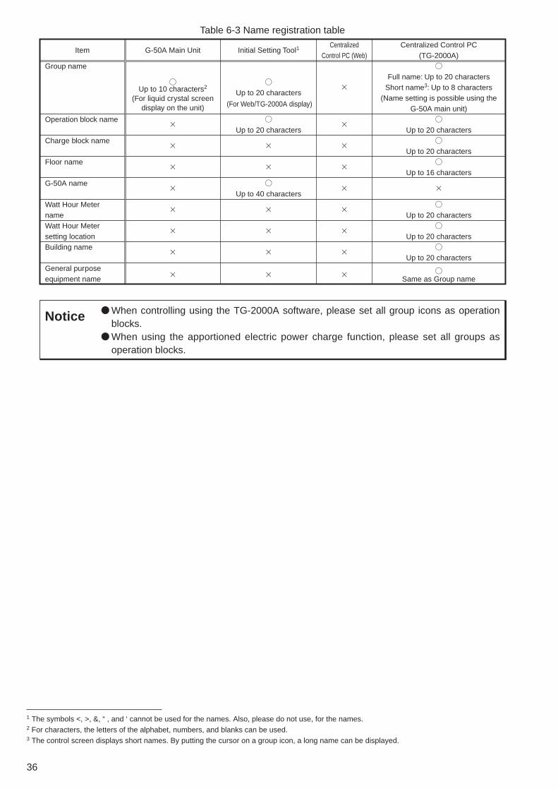
36
Table 6-3 Name registration table
Item
Group name
Operation block name
Charge block name
Floor name
G-50A name
Watt Hour Meter nameWatt Hour Meter setting locationBuilding name
General purposeequipment name
G-50A Main Unit
Up to 10 characters2
(For liquid crystal screen display on the unit)
Initial Setting Tool1
Up to 20 characters
Up to 20 characters
Up to 40 characters
Centralized Control PC (Web)
Centralized Control PC(TG-2000A)
Full name: Up to 20 charactersShort name3: Up to 8 characters
(Name setting is possible using the G-50A main unit)
Up to 20 characters
Up to 20 characters
Up to 16 characters
Up to 20 characters
Up to 20 characters
Up to 20 characters
Same as Group name
(For Web/TG-2000A display)
Notice ● When controlling using the TG-2000A software, please set all group icons as operationblocks.
● When using the apportioned electric power charge function, please set all groups asoperation blocks.
1 The symbols <, >, &, “ , and ‘ cannot be used for the names. Also, please do not use, for the names.2 For characters, the letters of the alphabet, numbers, and blanks can be used. 3 The control screen displays short names. By putting the cursor on a group icon, a long name can be displayed.

37
Table 6-4 PC specifications
ItemPCCPU
OS
HDD
MemoryDisplay resolutionInterface
Remarks
Monitoring using the web browserPC/AT compatiblePentium 133MHz or faster
Windows98/Me/2000/XPInternet Explorer 5.0 or later version (Java VM 5.0 or later version*)–
64MB or more1024 ✕ 768 or betterLAN port (10BASE-T)
When switching between screens and when updating operations, the data update operation necessary.Internet Explorer 5.0 or later version
Monitoring using the integrated software (TG-2000A)PC/AT compatible-1No. of air-conditioning units 1000 or less: Pentium4 1.8GHz or fasterNo. of air-conditioning units 1001 or more: Pentium4 1.8GHz or faster (Case of temp. trend use : 2.8GHz or faster)*Pentium4 2.8GHz or faster is recommendedWindows2000/XP Professional2
Standard 6GB or more3
(2GB or more of Cdrive free space necessary)When using the trend function, the drive used for automatic output must have the following free space according to the number of groups.200groups=2GB, 500groups=5GB, 1000groups=10GB, 2000groups=20GB
Wide area 20GB or more (Free space)256MB or more1024 ✕ 768 or betterLAN port (10BASE-T)Modem4
Automatic update with operation status updates every minute and abnormalities every three minutes.
* The Java VM (Microsoft VM) version can be confirmed using the following steps.When the software is an earlier version than 5.0, please update to the latest version using the Windows Update feature.[Version confirmation method]1. Please select [Designate File Name and Execute] from the [Start] menu.2. For Windows 98 and Windows Me, please input [COMMAND] and press the Enter key.
For Windows 2000 and Windows XP, please input [CMD] and press the Enter key.3. Please input [jview] at the command prompt display that appears. Next, press the Enter key.4. At the top line, a message similar to the one below appears to confirm the current version (below, lower line)
[Microsoft (R) Command-line Loader for Java Version x.yy.zzzz]5. When the version is older than 5.0, please update to a more recent version.
1 Operation has been confirmed for IBM, Hp Compaq and DELL2 Please note that use is not possible for Windows(R) XP Home Edition.3 A minimum of 4GB is recommended for the C-drive.4 When performing remote monitoring/operation, a PC equipped with a modem or a data/FAX modem card is required.
6.1.2 Centralized control PC (local arrangement)
Table 6-4 indicates the minimum specifications the PC required to conduct monitoring using the integratedsoftware or the Web browser, should satisfy. Please arrange locally for a PC satisfying the specificationsoutlined below.

38
6.2 About password controlWhen performing centralized control using a Web browser or the TG-2000A software, it is possible torestrict operations to approved users by setting a password to perform operations or functions please referto section 2,3 for function licence.
6.2.1 Password control when using a Web browser
(1) For public users
A public user is a user who enters through the [index.html] web page.This type of user can only operate and monitor the operation status of air-conditioning units.The default password for public users is [guest].
(2) For administrators
An administrator is a user who enters through the [administrator.html] web page.This type of user can operate and monitor the operation status of air-conditioning units in addition tosetting their schedules (optional), monitoring mulfunction log, setting the current timetable, monitoringsending error mail log and changing user names passwords.The default password for administrators is [admin].
6.2.2 Password control when using the TG-2000A software
(1) For system administrators
This is the password for system administrators.Inputting the current password enables transferring to the default selection screen.Furthermore, when transferring to the default selection screen by using this password, the passwordsfor [System Administrator] and [Maintenance User] can be changed.The default password for the system administrator is [SYSTEM].
(2) For maintenance users
This is the password for maintenance users.Inputting the current password enables transferring to the default selection screen. Furthermore, when transferring to the default selection screen by using this password, the passwordsfor [Maintenance] and [Maintenance User] can be changed, in addition to the [Charge Setting] controlscreen.The default password for the maintenance user is [Maintenance].
Request ● Please take care the password does not leak to a third party who has no permission tomake changes in the system. The password can be changed with the password function.

39
6.3 Setting When the Remote Monitoring isconducted
Using the modem and the dial-up router enables the remote monitoring and the remote operation.When conducting the remote monitoring, the parts which are shown in the Table 6-5 are necessary.When using the dial-up router which is shown in the Table 6-5, the line which can be connected from theremote place is decided by the telephone line type of the place where the G-50A is installed. Select theline of the remote place to match the on-site line in accordance with the Table 6-6.
Figure 6-2 Remote monitoring system
Allows confirming the operation status of ** branch office and operating the air conditioner from the remote place.
Remote place
Computer (with modem)
** main office
G-50A
Computer for centralized control
Dial-up router
Public line network
** branch office
Field
Table 6-5 Remote monitoring systemParts name
HUB for 10BASE-T
10BASE-T LAN straight cable (twist pair cable)Dial-up router
RemarkWhen the number of connected G-50A and computers exceeds the number of HUB ports with a built-in dial-up router or when extending the wiring distance, this HUB is necessary.
Select the LAN inside the building thorough the public line and select the dial-up router which can perform the data communication.
On-site line
Analog line
ISDN line
Line of remote placeAnalog line ISDN line
*1
Table 6-6 Matching line chart
Notes
● As the communication speed of the analog line is slow, using the line whosecommunication speed is fast, such as ISDN line, is recommended.
● Although ADSL was formally an analog line, the data is sent separately for datacommunication and for telephone communication. Use a splitter to separate the data fordata side and for the telephone side.Although the modem is connected to the data side of ADSL, the modem cannot makedial-up connection. Therefore, the modem cannot be connected even if a phone call ismade from outside.ADSL connection is currently under consideration.
1 When ISDN is used in the field, check the dial-up router specification whether to receive incoming signal from the analog line of the remote place.

40
6.3.1 Setting procedure in the Field
(1) Set the dial-up router
Set the dial-up router, so that the received phone call (data communication) is connected to the LANside or set the IP address for the dial-up router or for the remote computer.[192.168.1.254] is recommended for the IP address for the dial-up router, and [192.168.1.211] isrecommended for the IP address for the telephone line of the computer of the remote place.For the IP address for the computer LAN of the remote place, set other than [192.168.1.*] to avoid thesame address for the field.
(2) Set the G-50A network.
Set the IP address for G-50A, the subnet mask and the gateway address with the initial setting tool.For the gateway address, set the IP address for the dial-up router.
Figure 6-3 Remote monitoring system setting example
Modem
Dial-up router IP address : 192.168.1.254 IP address : 192.168.1.211
Set the IP address for the computer other than [192.168.1.*] to avoid the same address for the network system, as the IP address for telephone line is [192.168.1.211]. (Example) 192.168.2.1
Web monitoring computer or air conditioning control computer (integrated software: TG-2000A)
Web monitoring computer
IP address : 192.168.1.1Subnet mask : 255.255.255.0Gateway : 192.168.1.254
IP address : 192.168.1.101Subnet mask : 255.255.255.0Gateway : N/A
Modem and mobile phone
Public line network
G-50A
*[192.168.1.254] is recommended for the IP address of the dial-up router. Refer to the dial-up router instruction manual for the setting method of the IP address.
*When using the dial-up router without modem function, it is necessary to connect the modem (for analog and for ISDN) between the dial-up router and the public line network.
1 When setting the same address, the communication data is output from the LAN port of the computer. Therefore, the data communication cannot be made thorough the public line.
2 The gateway address can be set only with the initial setting tool. (Other addresses can be set with G-50A itself.)

41
6.3.2 Setting Procedure at the Remote Place
(1) Connect the modem and make the dial-up setting
Connect the modem to the computer for monitoring and make the dial-up setting.Create a new dial-up connection with [Network Setting] in the control panel, and set the local telephonenumber, the user’s name which is set for the dial-up router, and the password, so that the modem canbe connected to the dial-up router which is installed in the field.
(2) When monitoring with the Web browser
When monitoring with the Web browser, click the dial-up connection which is created in the item (1),connect with the field, and connect to the Web page of G-50A in the same way of monitoring inside thebuilding.
(3) Conduct monitoring with wide area mode version TG-2000A
When conducting remote monitoring of multiple buildings with TG-2000A, install wide area modeversion TG-2000A1.When starting wide area mode version TG-2000A, the site change tool will appear. Click the building towhich the modem is connected, and connect the modem. After connecting the modem, monitoring canbe conducted in the same way as the usual TG-2000A.
With wide area mode version TG-2000A, errorinformation for each building can be acquired by e-mailand it can be displayed.To use that function, click the mail tool icon on thedesktop, and make the mail-related setting. After thesetting, when the error mail is received, the buildingname and the error code will appear.
1 Wide area function can be used with TG-2000A Ver.4.60 or later. In the middle of the TG-2000A installation, the selection screen between the wide area mode and the standard mode appears. Select the [wide area mode], and perform the installation. Only either the wide area mode or the standard mode can be installed on a computer.
Notes
● When using the mail tool of wide area mode version TG-2000A, make the error mailsetting in the field which is shown in the next chapter.
● When using wide area mode TG-2000A, the LAN connection name which is set on theOS and the dial-up name should be less than 30 letters.
● When acquiring the error mail from other than the place where the dial-up is connected(such as LAN in the office), clear the check box for [use default gate on remote network]in the TCP/IP detail setting for dial-up connection.

42
6.4 Setting for Transmission of Error MailAs the error mail is transmitted via e-mail, it is necessary to contract with a provider.To use the error mail transmission function, set the mail address which is acquired at the time of contract,and the connection ID for Internet connection to the G-50A and the dial-up router.When transmitting the error mail, the parts which are shown in the Table 6-7 are necessary.The setting of transmission of error mail can be made only with the initial setting tool.
Figure 6-4 System of transmission of error mail
From : Mitsubishi Building (000001)Date : 13/03/2004 12:04:21Error unit : 059Error code : 1291Status : Occurence
Dial-up routerG-50A
Computer for centralized control
Field
**branch office
Internet provider
Public line networkPi! Pi! ...
Malfunction
Table 6-7 Necessary parts for transmission of error mailParts name
HUB for 10BASE-T
10BASE-T LAN straight cable (twist pair cable)Dial-up router
RemarkWhen the number of connected G-50A and computers exceeds the number of HUB ports with a built-in dial-up router or when extending the wiring distance, this HUB is necessary.
This dial-up router is necessary to connect to the mail server of the Internet provider.

43
6.4.1 Preparation for Transmission of Error Mail
(1) Contracts with a provider for mail transmission on the customer side.
Contract with an Internet provider. (Except for when there is an in-house LAN with a mail server in suchas your own building.)A provider contract on which access point, user ID, and certification password are written will be sentlater.The provider contract is necessary for the G-50 body setting and the dial-up router setting.
(2) IP address information of mail server
The access method may be shown in the provider contract; however, most providers do not disclose IPaddress.In this case, acquire the IP address of the mail server in compliance with the following procedures.Access to the access point by using the dial-up function with the monitoring computer, and create anenvironment where the internet can be accessed.Run MS-DOS prompt (command prompt for Windows 2000/XP) with the provider connected.To acquire the IP address of the mail server, enter “PING mail server name for transmission (SMTPserver name) 1”.
6.4.2 Setting Method for Transmission of Error Mail
(1) Make the setting for dial-up router.
Set the telephone number of the provider access point, the access ID and the password which arenotified at the time of contract to the dial-up router.
(2) Make the setting for G-50A network.
Make the setting of the IP address of G-50A, the subnet mask, and the gateway address with the initialsetting tool.For the gateway address, use the IP address of the dial-up router.
(3) Make the setting for G-50A mail.
Set the mail address which is notified from the provider, the IP address of the mail server, and the placewhere to send the error mail with the initial setting tool.
Figure 6-5 Setting example for transmission of error mail
Modem
Dial-up router IP address : 192.168.1.254
IP address : 192.168.1.1Subnet mask : 255.255.255.0Gateway : 192.168.1.254
IP address : 192.168.1.101Subnet mask : 255.255.255.0Gateway : N/A
* [192.168.1.254] is recommended for the IP address of the dial-up router. Refer to the dial-up router instruction manual for the setting method of the IP address.
* When using the dial-up router without modem function, it is necessary to connect the modem (for analog and for ISDN) between the dial-up router and the public line network.
Mail sending
G-50A Web monitoring computerComputer, mobile phone, or PHS from which mail can be read.
Internet provider
Public line network etc.Public line network
Mail receiving
Modem etc.
1 Mail server name for transmission is the mail server name which is used when the mail is sent. The name will be notified from the provider at the time of contract.
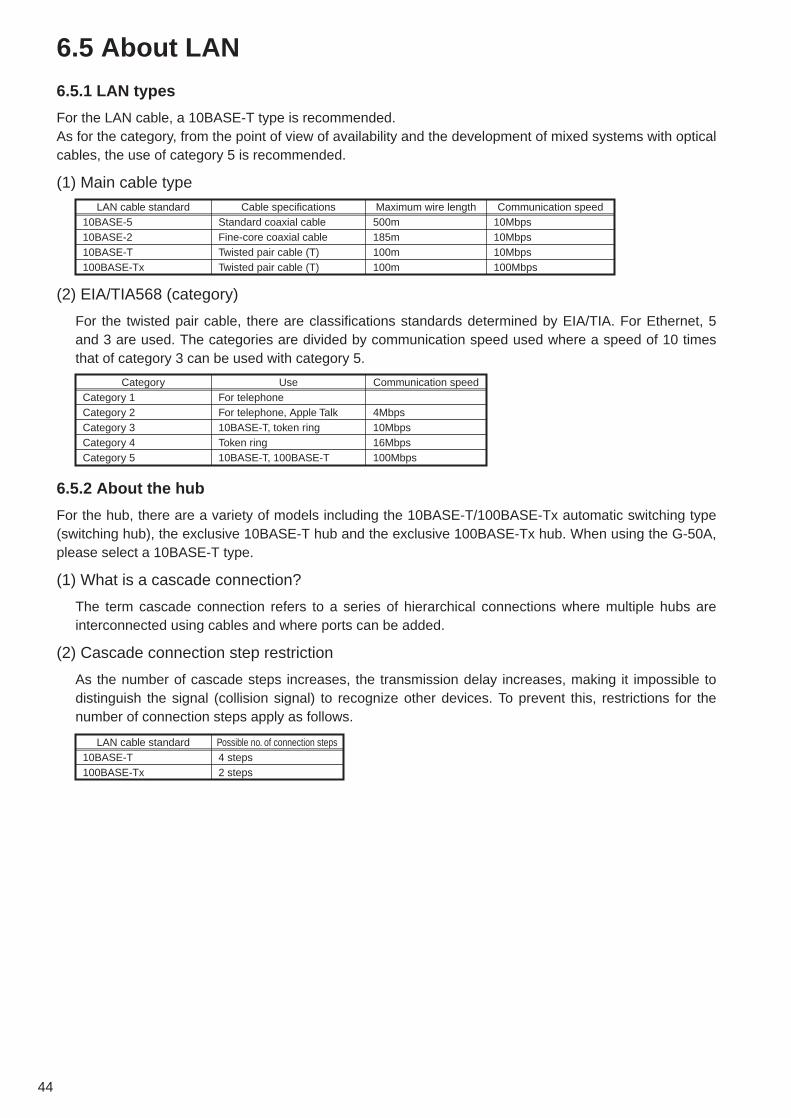
44
6.5 About LAN
6.5.1 LAN types
For the LAN cable, a 10BASE-T type is recommended.As for the category, from the point of view of availability and the development of mixed systems with opticalcables, the use of category 5 is recommended.
(1) Main cable type
6.5.2 About the hub
For the hub, there are a variety of models including the 10BASE-T/100BASE-Tx automatic switching type(switching hub), the exclusive 10BASE-T hub and the exclusive 100BASE-Tx hub. When using the G-50A,please select a 10BASE-T type.
(1) What is a cascade connection?
The term cascade connection refers to a series of hierarchical connections where multiple hubs areinterconnected using cables and where ports can be added.
(2) Cascade connection step restriction
As the number of cascade steps increases, the transmission delay increases, making it impossible todistinguish the signal (collision signal) to recognize other devices. To prevent this, restrictions for thenumber of connection steps apply as follows.
LAN cable standard10BASE-510BASE-210BASE-T100BASE-Tx
Maximum wire length500m185m100m100m
Communication speed10Mbps10Mbps10Mbps100Mbps
Cable specificationsStandard coaxial cableFine-core coaxial cableTwisted pair cable (T)Twisted pair cable (T)
(2) EIA/TIA568 (category)
For the twisted pair cable, there are classifications standards determined by EIA/TIA. For Ethernet, 5and 3 are used. The categories are divided by communication speed used where a speed of 10 timesthat of category 3 can be used with category 5.
CategoryCategory 1Category 2Category 3Category 4Category 5
Communication speed
4Mbps10Mbps16Mbps100Mbps
UseFor telephoneFor telephone, Apple Talk10BASE-T, token ringToken ring10BASE-T, 100BASE-T
LAN cable standard10BASE-T100BASE-Tx
Possible no. of connection steps4 steps2 steps

45
(3) Switching hub
The switching hub means the hub that controls traffics at exchanging packets (communication data)among plural networks, and send packets to a specified address.Different from ordinary hubs, it carries out one-to-one communications among respective ports,accordingly, even when one set of ports is communicating, other ports can communicate freely. By thisfunction, conflict of signals can be restricted, and network performance can be improved.Fig. 6-2 shows the differences between an ordinary hub and a switching hub.When communication is made from the personal computer at 192.168.1.2 to the personal computer at192.168.1.3, in the case of an ordinary hub, communication is sent also to the personal computer at192.168.1.1. While, in a switching hub, communication is sent to only the destination that you want tocommunicate.
6.5.3 LAN wire length
A 10BASE-T network connected to the G-50A may have a maximum wire length of 100m.Consequently, when the LAN wire length exceeds 100m, the use of hubs will extend the maximum lengthto 500m.
Notice ● Be sure to always use a hub.● Restrictions apply to the number of cascade connections when using hubs. Please
observe these restrictions.
100m
HUB HUB HUB HUB
500m
G-50ACentralizedcontrol PC
Transmitting communication to all routes
Not transmitting to routes except that desired by switching.
Ordinary HUB
192.168.1.1 192.168.1.2 192.168.1.3 192.168.1.1 192.168.1.2 192.168.1.3
Switching
Figure 6-2 Switching hub concept
Notice ● By use of a switching hub, it is possible to add hubs exceeding the connection stagerestrictions specified in the section 6.5.3, and to expand the distance.
Example: In the case where 2-stage cascade connection is made by 100 Base-TXrepeater hub or the like, by use of a switching hub, the hub can beconnected to 2-stage cascade.
● When to connect 2 switching hubs, there is logically no restriction in the number of cascadeconnection stages, cable length (between nodes) or so. However, if the load of networkbecomes extremely high, delay may result, causing network connection problems.
● As for the details of switching hub, refer to the operation manual attached to eachswitching hub.
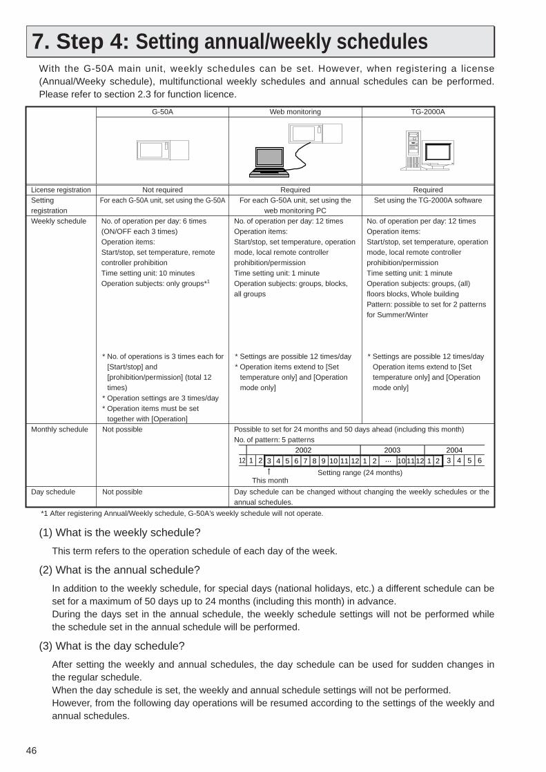
46
7. Step 4: Setting annual/weekly schedulesWith the G-50A main unit, weekly schedules can be set. However, when registering a license(Annual/Weeky schedule), multifunctional weekly schedules and annual schedules can be performed.Please refer to section 2.3 for function licence.
License registrationSetting registrationWeekly schedule
Monthly schedule
Day schedule
Not requiredFor each G-50A unit, set using the G-50A
No. of operation per day: 6 times(ON/OFF each 3 times)Operation items:Start/stop, set temperature, remote controller prohibitionTime setting unit: 10 minutesOperation subjects: only groups*1
* No. of operations is 3 times each for [Start/stop] and [prohibition/permission] (total 12 times)
* Operation settings are 3 times/day* Operation items must be set
together with [Operation]Not possible
Not possible
RequiredFor each G-50A unit, set using the
web monitoring PCNo. of operation per day: 12 timesOperation items:Start/stop, set temperature, operation mode, local remote controller prohibition/permissionTime setting unit: 1 minuteOperation subjects: groups, blocks, all groups
* Settings are possible 12 times/day* Operation items extend to [Set
temperature only] and [Operation mode only]
RequiredSet using the TG-2000A software
No. of operation per day: 12 timesOperation items:Start/stop, set temperature, operation mode, local remote controller prohibition/permissionTime setting unit: 1 minuteOperation subjects: groups, (all) floors blocks, Whole buildingPattern: possible to set for 2 patterns for Summer/Winter
* Settings are possible 12 times/dayOperation items extend to [Set temperature only] and [Operation mode only]
G-50A Web monitoring
Day schedule can be changed without changing the weekly schedules or the annual schedules.
Possible to set for 24 months and 50 days ahead (including this month)No. of pattern: 5 patterns
TG-2000A
1122002 2003 2004
2 3 4 5 64 5 6 7 8 9 1 2 10 11 12 1 2···10 11 123
This monthSetting range (24 months)
*1 After registering Annual/Weekly schedule, G-50A’s weekly schedule will not operate.
(1) What is the weekly schedule?
This term refers to the operation schedule of each day of the week.
(2) What is the annual schedule?
In addition to the weekly schedule, for special days (national holidays, etc.) a different schedule can beset for a maximum of 50 days up to 24 months (including this month) in advance.During the days set in the annual schedule, the weekly schedule settings will not be performed whilethe schedule set in the annual schedule will be performed.
(3) What is the day schedule?
After setting the weekly and annual schedules, the day schedule can be used for sudden changes inthe regular schedule.When the day schedule is set, the weekly and annual schedule settings will not be performed. However, from the following day operations will be resumed according to the settings of the weekly andannual schedules.
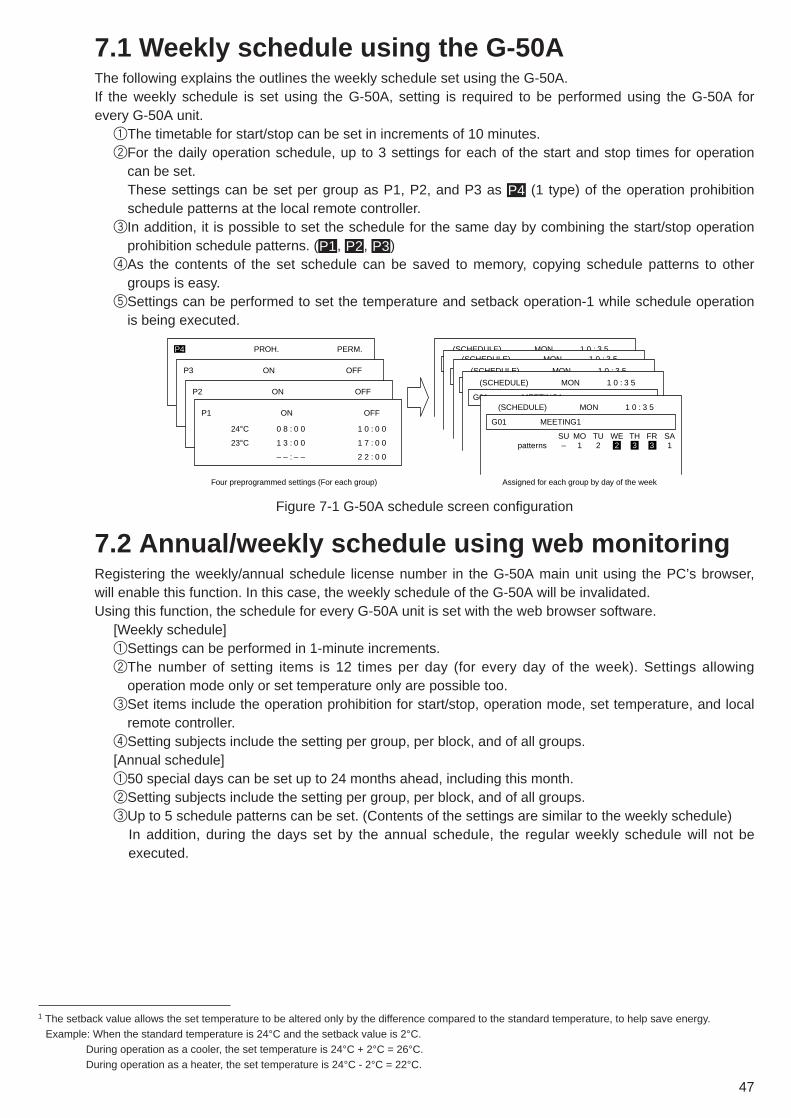
47
7.1 Weekly schedule using the G-50AThe following explains the outlines the weekly schedule set using the G-50A.If the weekly schedule is set using the G-50A, setting is required to be performed using the G-50A forevery G-50A unit.
1The timetable for start/stop can be set in increments of 10 minutes.2For the daily operation schedule, up to 3 settings for each of the start and stop times for operation
can be set. These settings can be set per group as P1, P2, and P3 as (1 type) of the operation prohibitionschedule patterns at the local remote controller.
3In addition, it is possible to set the schedule for the same day by combining the start/stop operationprohibition schedule patterns. ( , , )
4As the contents of the set schedule can be saved to memory, copying schedule patterns to othergroups is easy.
5Settings can be performed to set the temperature and setback operation-1 while schedule operationis being executed.
P3P2P1
P4
(SCHEDULE) MON 1 0 : 3 5(SCHEDULE) MON 1 0 : 3 5
(SCHEDULE) MON 1 0 : 3 5
G01 MEETING1
(SCHEDULE) MON 1 0 : 3 5
G01 MEETING1
patterns
(SCHEDULE) MON 1 0 : 3 5
SU MO TU WE TH FR SA– 1 2 2 3 3 1
P4
P3
P2
P1
24°C
23°C
0 8 : 0 0
1 3 : 0 0
– – : – –
1 0 : 0 0
1 7 : 0 0
2 2 : 0 0
Four preprogrammed settings (For each group) Assigned for each group by day of the week
PROH. PERM.
OFF
OFF
OFF
ON
ON
ON
7.2 Annual/weekly schedule using web monitoringRegistering the weekly/annual schedule license number in the G-50A main unit using the PC’s browser,will enable this function. In this case, the weekly schedule of the G-50A will be invalidated.Using this function, the schedule for every G-50A unit is set with the web browser software.
[Weekly schedule]1Settings can be performed in 1-minute increments.2The number of setting items is 12 times per day (for every day of the week). Settings allowing
operation mode only or set temperature only are possible too.3Set items include the operation prohibition for start/stop, operation mode, set temperature, and local
remote controller.4Setting subjects include the setting per group, per block, and of all groups.[Annual schedule]150 special days can be set up to 24 months ahead, including this month.2Setting subjects include the setting per group, per block, and of all groups.3Up to 5 schedule patterns can be set. (Contents of the settings are similar to the weekly schedule)
In addition, during the days set by the annual schedule, the regular weekly schedule will not beexecuted.
Figure 7-1 G-50A schedule screen configuration
1 The setback value allows the set temperature to be altered only by the difference compared to the standard temperature, to help save energy.Example: When the standard temperature is 24°C and the setback value is 2°C.
During operation as a cooler, the set temperature is 24°C + 2°C = 26°C.During operation as a heater, the set temperature is 24°C - 2°C = 22°C.

48
Setting unitSelects the setting unit.
Day of the week selectionSelects the day of the week for the schedule to be set.
Save/do not saveSets saving or not saving when pushing the settings save button.
Schedule contentsDisplays the schedule contents.
Settings save buttonSaves the schedule contents. Settings are not saved if this button is not pressed.
Selection button Sets the schedule contents.Delete buttonDeletes the contents of the schedule.
Block nameSelects the block to be set.
Group nameSelects the group to be set.
Group numberSelects the group to be set.
Undo buttonReturns any changes to
the original contents.
The settings of the operation contents are performed by setting unit (group, block, all blocks) as displayed in the screen on the left. The setting of the operation can be set up to 12 sets each day.
Figure 7-2 Weekly schedule set screen
Setting unitSelects the setting unit.
Pattern selectionSelects the pattern to set the schedule.
Save/do not saveSets saving or not saving the schedule pattern when pushing the settings save button.
Schedule contentsDisplays the schedule contents.
Selection button Sets the schedule contents.
Delete buttonDeletes the contents of the schedule.
Save/do not saveSets saving or not saving the pattern assigned to a certain day when pushing the settings save button.
Calendar buttonAssigns the pattern to a specific day
Settings save buttonSaves the schedule contents. Settings are not saved if this button is not pressed.
Block nameSelects the block to be set.
Group nameSelects the group to be set.
Group numberSelects the group to be set.
Undo buttonReturns any changes to
the original contents.
Figure 7-3 Annual schedule set screen

49
7.3 Weekly schedule of the integrated softwareRegistering the weekly/annual schedule license number in the G-50A main unit using the PC’s browser,will enable this function. In this case, the weekly schedule of the G-50A will be invalidated while the datapreviously set with the web monitor will be validated.For the schedule set with the TG-2000A software, settings are set per target unit (group, block, floor, etc.)in the schedule set screen of the TG-2000A.
12 operation settings are possible for every day of the week. It is also possible to set the contents for [Operation mode] only or [Setting temperature] only.
For the setting data two patterns, namely [Summer Master] and [Winter Master] are available to facilitate switching depending on the season.
Figure 7-4 TG-2000A schedule set screen
TG-2000A
Schedule data[Summer Master]
Schedule data[Winter Master]
Schedule data[G-50A Master]
Schedule data[G-50A Master]
G-50A
Web control PCBy absorbing the schedule data of the G-50A, the data is entered in the [G-50A Master] within the TG-2000A software.
By transmitting the [Summer Master] and [Winter Master] stored in the TG-2000A software, the G-50A will execute that schedule.* Switching between the [Summer Master] and the [Winter Master] requires the corresponding
operation of the TG-2000A software.
Displays the contents of the G-50A Master.
Figure 7-5 TG-2000A schedule chart
The schedule functions when performed with the TG-2000A are similar to the settings performed with theWeb browser, except for the possibility to store the two patterns [Summer Master] and [Winter Master].The [Summer Master] and [Winter Master] set with TG-2000A are stored, to enable transmission to the G-50A main unit in accordance with the user’s needs. By transmitting these data to the G-50A, they becomethe [G-50A Master data] and will be executed by the schedule of the G-50A main unit.

50
8. Step 5: Charging Function of Energy Charge MeasuringThis step is to set the charging function of measuring instruments to be performed by TG-2000A.This setting is required to use the charging function by measuring instruments. Since this function is optional,license registration to the G-50A unit is needed to use the charging function by measuring instruments.
8.1 OutlineBefore explaining the charging function by measuring instruments, each term used here is introduced.
(1) What is the basic charge?
This indicates the contracted basic charge of each measuring instrument (electric power, gas, city water, calorie meter). The basic charge is set in each tenant (charge block) for air conditioning energy charging. While for the direct reading ofother measuring instruments, it is set in each measuring instrument.As for air conditioning, the basic charge represents the charge of air conditioning system for each tenant, apportioned fromthe contracted electric power charge of whole building. The monthly charge is fixed.
[Example of calculation method of basic charge]1The contract charge of air conditioning in calculated from the contact electric charge of a whole building.
Basic charge (Yen) = × Contract electric capacity × Capacity unit price
2This basic charge is divided in proportion with the air conditioning electric capacity per tenant (chargeblock).
Air conditioner electric capacity of control targetTotal electric system capacity of whole building
Basic charge of charge blockIn the case of the apportioned system, the basic charge is set in each charge block.
Basic charge of measuring equipment
In the case of direct reading type measuring equipment,
the basic charge is set in each measuring
equipment.
The basic charge can not be set in the case of the electric power manual input system. It shall be added separately.
Figure 8-1 TG-2000A basic charge setting screen
[Apportioning of air conditioning power consumption]Since the watt-hour meter value of power consumption is apportioned by judging the operation status of the indoor unit from detailedcommunication between the indoor and outdoor unit, this value can not be applied to the business certificate legally defined.The same limitation is applied to the case of direct reading of measuring instrument unit.In order to employ this system, therefore, it is recommended to conclude an agreement or contract between the building owner andtenants stipulating that [The air conditioning charge should be collected through apportioned calculation based on the operation status(including the temporary processing measure at trouble)]. (1) This system does not measure the power consumption of each indoor unit directly.(2) As the system estimates the power consumption of air conditioning, the valued obtained herewith may not be applied to the certificate
of business transaction.(3) Even if the operation time of air conditioners is same, the power consumption differs depending on the operating status.(4) As air conditioners are powered even when they are stopping, the power consumption will be charged.(5) One watt-hour meter should be connected to one air conditioner. If connected to plural air conditioners, an error will be caused due to
the apportioning of total power consumption.(6) At the failure of PC, G-50A or PLC, the average apportioned value in the past may be adapted for temporary transaction as a solution.(7) As the power consumption and gas consumption is taken in the form of a pulse, the performance and accuracy are depending on that
of the measuring instruments employed. Under this circumstance, we are not liable for the performance and accuracy presented.(8) As the resultant air conditioning charge is rounded to the nearest whole number at a figure not shown here, please note that an error
generates between the air conditioning charge of watt-hour meters and that of the block total.
CAUTION

51
(2) What is charge?
This represents the charge of electric power, gas or water consumed by each air conditioner or tenant(In the case of using electric power count by PC direct connect (Watt Hour Meter (RS-485)), onlyelectric power can be counted). The charge of such consumption can be calculated by the following 2methods, and the output can be presented in printer output or file output in CSV format.● Calculation for clearing day
On the clearing day registered to TG-2000A, the monthly charge is calculated automatically. Thebasic charge is also added. The clearing day may be selected in two ways, from the clearing dayspecified or the end of the month. In the case of the clearing day specified, the day of 29th, 30th or31st can not be specified, but the specifying the end of the month conducts clearing at the end of themonth. The result of clearing can be selected for printer output or file output.
● Calculation for specified dateThe charge may be calculated for any desired period covering 122 days from and including theformer day. (The basic charge is not included.)
Month end specifiedSpecify when the end of the month is desired to select.This setting clears based on the operating record until the final day monthly.
Date specifiedSpecify when a fixed day is
desired for clearing. However, the day of 29th, 30th or 31st
can not be specified.
Figure 8-2 TG-2000A clearing day specifying screen
Target for calculationSelect the target for clearance.
Start/finish selectionSelect the period to be cleared.
Clearance can be performed for the past 122 days.
Figure 8-3 TG-2000A clearance period specifying screen
(3) What is the time frame for charging?
The charge of one calendar day can be set with 5 charge units to 10 time frames divided.This setting can change the charge unit depending on the time frame in the morning, after noon,overtime or weekend. As the charging unit can be set to each measuring instrument individually1,sophisticated operation according to the types of measuring instruments can be performed. However,the setting of time frame should be applied collectively for each measuring instrument.
In the case of electric power count by PC direct connect (RS-485WHM), charging unit (daytime,nighttime, weekday, weekend and seasons) can be set up.
Time frame dividing markIndicates the division of time frame.Allows dividing each weekday in 10 divisions.The unit of time is 10 minutes.
Charging time frameIndicates the time frame for charging.The content of this setting may commonly be used for all measuring instruments.
Week day buttonClicking displays the menu of set/cancel/copy/paste.
Charging unit settingAllows setting the charging
unit of watt-hour meter.Other measuring instruments
(for city water, gas, calorie) may be set on other screen (Measuring instrument unit
price screen).
Figure 8-4 TG-2000A charging time frame setting screen
1 Indicates air conditioning, electricity 1, electricity 2, gas, city water and calorie, five types in total.

52
(4) What is the seasonal charge?
The electrical power charge can be divided into the summer seasonal charge and normal charge.Because of this, the following management can be adapted for example; “As a ratio of using air conditioner rises in the summer (July ~ September) and electric powerconsumption of a whole building increases accordingly, higher power rate may be applied in this period.” The period of the seasonal charging may be applied by specifying the date of start and end respectively.
Seasonal charging period settingSets the seasonal charging period.
Seasonal charge settingSelects setting or no setting.
Default value represents “No setting.”
Figure 8-5 TG-2000A seasonal charge setting screen (ex, electric power manual input, pulse count)
(5) Setting of special day (Setting of annual charge)
Besides the items (3) and (4) above, a special day of up to 50 days can be set in a range of 24 monthsin future (including this month).For the special days, 5 patterns may be set and the patterns may be assigned to 50 days maximum.The unit price of the charging changes by a fact whether the assigned day belongs to the seasonalcharging period or normal charging period.
This function can not be used in the case of electric power count by PC direct connect (RS-485WHM).
Pattern set/change buttonSets or changes the charging patterns.
Displays the number of set daysDisplays the number of the day set with annual rate.Can be set 50 days maximum for 24 months in future including the present month.
Pattern setting5 patterns can be set.
The pattern name can be changed (up to 10 characters).
Pattern set/cancelClicking the date sets or cancels
the pattern being selected.
Figure 8-6 TG-2000A annual charge setting screen

53
8.2 Selection of Charging FunctionThe G-50A system provides the following 4 methods to calculate the charge by measuring instruments.For the objective models that can be charged by each method, please refer to Table 4-3.
(1) Manual input of electric power consumption
This method is only applicable to the charging of electric power consumed by air conditioners.Without using a watt-hour meter, this method calculates electric power consumption in a ratio of eachtenant (charge block) by using the daily operation amount and the set capacity of the air conditioner.Utilizing the electric power apportioned charging calculation tool of TG-2000A, the reading value of thewatt-hour meter of the outdoor and indoor units is input manually to calculate the air conditioningcharge.As the basic charge can not be set by this method, it should be added by the user.
(2) Watt-hour meter pulse counting (Apportioning method)
This method is only applicable to the charging of electric power consumed by air conditioners.By apportioning the electric power measured by the watt-hour meter connected to the air conditionerand the daily operation of the air conditioner, the electric power consumption per tenant (charge block)can be calculated by this method.
(3) Measuring instrument pulse counting (Direct reading method)
This charging method covers the Free Plan LOSSNAY for which the above apportioning method is notavailable, the air conditioning electric power of A-control models, the general electric power of lampsand plug sockets, and the charge of city water.In such cases, installing a measuring instrument for each charging block is needed. Charging is performed for each measuring instruments.
(4) Electric power count by PC direct connect (RS-485WHM)
This charging method is only applicable to the charging of electric power consumed by air conditioners.By apportioning the electric power measured by the watt-hour meter connected to the air conditionerand the daily operation of the air conditioner, the electric power consumption per tenant (charge block)can be calculated by this method.
Note● When using charge function by the watt-hour meter, use the PLC for counting electric
energy (Apportioning method). (Do not recommend using RS-485 WHM, becauseapportioning data may be lost due to blackout or computer malfunction.)

54
8.3 Basic Composition and Required Materials
8.3.1 Manual input of electric power consumption
This method is only applicable to the charging of electric power consumed by air conditioners.
(1) Basic composition
(2) Required materials
Table 8-1 shows the materials required to carry out the electric power manual input method.
Chargelicense
ME remotecontroller
ME remotecontroller
LOSSNAY
LOSSNAYUninterrupted power source (UPS)
Power supplyunit
PC for TG-2000A
Install TG-2000A software
G-50ADC12V
Input
Figure 8-7 Basic composition of electric power manual input method
Table 8-1 Materials required for simplified chargingName (Model name)
PC for TG-2000A
PC for apportioning
Integrated centralized control software (TG-2000A)Charge licenseWeb monitor licenseUninterrupted power sourse (UPS)2
ManufacturerPC/AT convertible unit
PC/AT convertible unit
Mitsubishi ElectricMitsubishi ElectricMitsubishi ElectricMitsubishi Electric (referense)
RemarksConfirmed operation of IBM, DELL, Hp Compaq.For PC spec., refer to Table 6-4.PC for apportioned calculation of each tenant using CSV file output from TG-2000A.Requires the table calculation software (EXCEL).1
Requires for each G-50A.Requires for each G-50A.FREQUPS A-series.(Line interactive system)
1 This software (apportioning support software) is in the install disk of TG-2000A. Use EXCEL 2000/XP or later.2 When [Deactivate] on the [Always connected to G-50A system] item is selected with TG-2000A Ver. 4.51 or later, the operation without UPS
connected is possible. (Charge calculation is made correctly during the computer’s start-up process even if the computer stops due to ablackout.)When UPS is connected, and there is a blackout in the middle of the charge calculation, the charge data may be damaged. Therefore, back upthe data occasionally.Moreover, when trend data is collected, it is recommended to connect UPS, so that the data is not deleted due to a blackout.

55
(3) Setting items
Table 8-2 shows the items of TG-2000A charging system setting and that of the charging required tocarry out the electric power manual input method.
Table 8-2 Setting items of the electric power manual input methodMajor item
Apportioning mode setting
Indoor unit setting
Charge block setting
Seasonal charge setting
Weekly charge setting
Annual charge setting
Currency setting
Subordinate itemApportioning standard data
Charge block setting methodCharge block settingRequirementSummer period settingUnit priceCharging time frame
Pattern settingSpecial day setting
DetailSelect one apportioning standard data from the below.
1 Capacity saving (operating capacity) --- Default2 Thermostat time (operating time)
Input the following data to each indoor unit.1 Indoor unit capacity (kW) (cooling)2 Indoor unit fan capacity (kW)
Select the same setting with operation block or new charge block setting.For setting of charge block newly, set it in a unit of operation block.Select whether changing the unit price by summer winter.When changing the unit price by seasons, set the period of summer.Set the unit price for 5 maximum.Set 5 unit prices to the 10 time frames maximum. When the seasonal rates have been set, set to the summer and winter respectively.Set 5 charging time frame patterns.Assign the 5 patterns previously set to 50 days a year. Type of currency set up

56
Chargelicense
Install TG-2000A software
Single-phase 200V
Single-phase 200V
Power supply unit
G-50A
DC12V
Input
3-phase 200V
Outdoor unit system watt-hour meter
Indoor unit system watt-hour meter
Indoor unit system watt-hour meter
PLC (Pulse counting software installed)
Uninterrupted power source (UPS) PC for TG-2000A
Figure 8-8 Basic composition of electric power pulse counting method
8.3.2 Watt-hour meter pulse counting (apportioning) method
This method is only applicable to the charging of electric power consumed by air conditioners.
(1) Basic composition
(2) Required materials
Table 8-3 shows the materials required to carry out the electric power pulse counting (apportioning)method.
[Selection of pulse counting software]The pulse counting software to be installed to PLC differs depending on the IP address of the PLC.Refer to Table 8-4 for selection. One set of PLC can count the measuring instruments up to 32 sets.
*In case of IP address needs to be changed, please ask to MITSUBISHI ELECTRIC for details.
Table 8-3 Materials required for electric power apportioned charging
Name (Model name)PC for TG-2000A
Integrated centralized control software (TG2000A)Charge licenseWeb monitor licensePLC
Electric power pulse counting softwareWatt-hour meter with pulse oscillatorUninterrupted power source (UPS)
MakerPC/AT convertible unit
Mitsubishi Electric
Mitsubishi ElectricMitsubishi ElectricMitsubishi Electric
Mitsubishi ElectricMitsubishi ElectricMitsubishi Electric (reference)
RemarksConfirmed operation of IBM, DELL, Hp Compaq.For PC spec., refer to Table 6-4.
Requires for each G-50A.Requires for each G-50A.PLC for pulse counting can be connected up to 5 sets.For the PLC specification, refer to Table 12-1.For detail, refer to Table 8-4.For the specification of the watt-hour meter, refer to Table 10-1.FREQUPS A-series.(Line interactive system)
Table 8-4 Watt-hour meter pulse counting softwareModel name of watt-hour meter pulse counting softwarePAC-YG11CDA
IP address192.168.1.151
ExplanationFixed to the left address.*

57
(3) Setting items
Table 8-5 shows the setting of measuring instrument of TG-2000A, charging system and charging setitems required for the electric power pulse counting (apportioning) method.
Table 8-5 Setting items of the electric power pulse counting methodMajor item
PLC quantity setting
PLC setting
Measuring instrument setting
Apportioning mode setting
Setting for outdoor unit to watt-hour meterOutdoor unit setting
Setting for indoor unit to watt-hour meter
Indoor unit setting
Charge block setting
Currency settingBasic charge setting
Seasonal charge setting
Weekly charge setting
Annual charge setting
Setting of measuring instrument unit price
Subordinate item
IP address
Installation site
Apportioning standard data
Processing of crankcase heater
Indoor unit apportioning mode
Charge block setting methodCharge block setting
Requirement for settingSummer period settingUnit price
Charging time frame
Pattern settingSpecial day settingUnit price
DetailSet the quantity of PLC to be connected.Max. 32 sets of measuring instrument can be set to 1 PLC. Max. 5 sets of PLC for pulse counting.Determine the IP address of PLC.The following is recommended for the default in TG-2000A.192.168.1.151 ~ 192.168.1.155The installation site of PLC can be set.The type (air conditioner, electric 1, electric 2, gas, city water, calorie), name, installation site and the pulse unit of measuring instruments are set.Select one apportioning standard data from the below 1 Capacity saving (operating capacity) --- Default2 Thermostat time (operating time)
Select the apportioning method of outdoor unit crankcase heater.1 Mode 1: Apportioning without special consideration (apportioning together)2 Mode 2: Separate apportioning --- Default value3 Mode 3: No apportioning
Select the apportioning method of power consumption of indoor unit. 1 Mode 1: No apportioning (installing watt-hour meter)2 Mode 2: Apportioning --- Default value
Set the outdoor unit connected to each watt-hour meter.
Set the crankcase heater capacity of each outdoor unit.(Automatic setting from the database of TG-2000A in principle)Set the indoor unit connected to each watt-hour meter.Be careful that A-control indoor unit or LOSSNAY can not be measured by same watt-hour meter.Input the following data to each indoor unit.1 Indoor unit capacity (kW) (under cooling mode)2 Indoor unit fan capacity (kW)3 Indoor unit heater capacity (kW)
(Automatic setting from the database of TG-2000A in principle)Select the same setting with operation block or new charge block setting.For setting of charge block newly, set it in the unit of operation block.Type of currency set upSet the basic charge to each charge block and measuring instrument (except for air conditioners).Select whether changing the unit price by summer and winter.When changing the unit price by seasons, set the period of summer.Set the unit price up to 5 watt-hour meters for air conditioning and that for other applications.Set 5 unit price frames to the 10 time frames maximum per weekday.When the seasonal rates have been set, set it to the summer and winter respectively. This setting is common for all measuring instruments.Set 5 charging time frame patterns.Assign the 5 patterns previously set to 50 days a year.In accordance with the classification of measuring instruments other than watt-hour meters, set five unit prices maximum.

58
8.3.3 Measuring instrument pulse counting (direct reading) method
(1) Basic composition
Chargelicense
Single-phase 200V
Single-phase 200V
Power supplyunit
Install TG-2000A software
InputLOSSNAY
LOSSNAY
Charge block
Charge block Charge blockIndoor unit system watt-hour meter
Indoor unit system watt-hour meter
Indoor unit system watt-hour meter
A measuring instrument should be installed for each charge block.
PLC (installed with pulse counting software)
PC for TG-2000A
Uninterrupted power source (UPS)
G-50A
DC12V
Figure 8-9 Basic composition of measuring instrument pulse counting (direct reading) method
(2) Required materials
Table 8-6 shows the materials required to carry out the measurement charging by direct reading. Thematerials same as that for the apportioning method are required.
[Selection of pulse counting software]The pulse counting software to be installed to PLC differs depending on the IP address of the PLC.Refer to Table 8-4 for selection. One set of PLC can count the measuring instruments up to 32 sets.
(3) Setting item
For this method, the contents of setting differ depending on the load to be measured. Conduct eachsetting by following the setting items shown in the electric power pulse counting (apportioning) method.
Table 8-6 Materials required for measuring instrument charging
Name (Model name)PC for TG-2000A
Integrated centralized control software (TG-2000A) Charging licenseWeb monitor licensePLC
Electric power pulse accounting softwareWatt-hour meter with pulse oscillator Water meter with pulse oscillatorGas meter with pulse oscillator Calorie meter with pulse oscillator Uninterrupted power source (UPS)
MakerPC/AT convertible unit
Mitsubishi Electric
Mitsubishi ElectricMitsubishi ElectricMitsubishi Electric
Mitsubishi Electric
Mitsubishi Electric
Mitsubishi Electric (reference)
RemarksConfirmed operation of IBM, DELL, Hp Compaq.For PC spec., refer to Table 6-4.
Requires for each G-50A.Requires for each G-50A.PLC for pulse counting can be connected up to 5 sets. For the PLC specification, refer to Table 12-1.For detail, refer to Table 8-4.
For the specification of the watt-hour meter, refer to Table 10-2.For the specification of measuring instruments, refer to Table 10-1.
FREQUPS A-series.(Line interactive system)

59
8.3.4 Power consumption PC direct reading system (Apportioning system)
This system can only be applied to the charging of power consumption by air conditioners.
(1) Basic configuration
Charge license
1-phase 200V
1-phase 200V
Transmission line powering unit
Install TG-2000A software
InputLOSSNAY
LOSSNAY
Indoor unit system watt-hour meter
3-phase 200V
Outdoor unit system watt-hour meter
Indoor unit system watt-hour meter
RS-485/RS-232C Converter
PC for TG-2000A
Uninterrupted power source system (UPS)
G-50A
DC12V
Figure 8-10 Basic configuration of power consumption PC direct reading system (RS-485 Watt-hour meter)
(2) Required materials
Table 8-7 shows the required materials to execute the power consumption PC direct reading system(RS-485 watt-hour meter system).
Table 8-7 Required materials for power consumption apportioned charging
Material name (Model name)PC for TG-2000A Integrated centralized control software (TG-2000A)Web monitor licenseCharge licenseRS-485 watt-hour meter
Uninterrupted power source (UPS)
MakerPC/AT compatible machineMitsubishi Electric
Mitsubishi ElectricMitsubishi Electric
Mitsubishi Electric (Reference)
RemarksAction verified with IBM, DELL, Hp Compaq
Requires for each G-50A systemRequires for each G-50A systemFor the watt-hour meter specification, refer to Table 10-3. Connectable up to 30 setsFREQUPS A Series(Line interactive system)

60
(3) Setting items
Table 8-8 shows the setting of the measuring instruments, charging system, and charge setting items ofTG-2000A required to execute the power consumption pulse counting system (apportioning system).
Table 8-8 Setting items of power consumption pulse counting system
Major itemWHM number setting
WHM setting
Apportioning mode setting
Setting between outdoor unit - watt-hour meterOutdoor unit setting
Setting between indoor unit - watt-hour meter
Indoor unit setting
Charge block setting
Currency settingBasic charge setting
Power rate setting
Minor item
AddressInstallation siteMaximum integrated value
Apportioning standard data
Transaction of crankcase heater
Apportioning mode of indoor unit
Setting method of charge blockSetting of charge block
Necessity of execution
Setting of seasonal periodUnit price
Charging time frame
DetailConnectable RS-485 watt-hour meter counts for 30 sets maximum.Setting the usable WHM.Setting the usable COM port.Usable WHM is specified (Refer to Table 10-3.)Deciding WHM addressPossible to set WHM installation locationSetting the maximum integrated value of WHM, watt-hour meter (kWh).Selecting one of the apportioning standard data of outdoor unit among two below.1 Capacity saving value (Consumed capacity) - - - Default value2 Thermostat time (Operating time)Selecting the transaction method of power consumption by outdoor unit crankcase heater.1 Mode 1 : Apportions not taking it specifically (apportioning
together)2 Mode 2 : Apportions separately - - - Default value3 Mode 3 : No apportioningSelecting the transaction method of indoor unit power consumption1 No apportioning (installing watt-hour meter)2 Apportions - - - Default valueSetting the outdoor unit connected to measuring instrument unitSetting the crankcase capacity of each outdoor unit(Basically it is set automatically from the database in TG-2000A)Setting the indoor unit connected to measuring instrument unitBe careful that indoor unit can not be measured with the same watt-hour meter of A-control indoor unit or LOSSNAY.Entering the data below for each indoor unit1 Indoor unit capacity (kW) (Cooling mode)2 Indoor unit fan capacity (kW) (Basically it is set automatically from the database in TG-2000A)Selecting to use the same block of operation block or set a charge block independentlySetting in a unit of the operation block to set a charge block independentlySelecting or setting the currency to useSetting the basic charge for each charge block and measuring instrument (other than that for air conditioning)Selecting the time frame only for daytime, or daytime and nighttime and the use of seasonal rateDefining the summer period when applying the seasonal rateSetting the unit price for air conditioning watt-hour meter, daytime and nighttime, and season (daytime and nighttime).Setting the charging time frame for the daytime and nighttime being set per weekday and weekend. When the seasonal rate is being set, set it individually.

61
8.4 Mechanism of Charge CalculationThe mechanism of electric power apportioned charge calculation by TG-2000A is given below.
Single-phase 200V
3-phase 200V
Indoor unit Indoor unit
Indoor unit Indoor unit
G-50A
PLC
HUB
Outdoor unit (M-NET)
Outdoor unit (M-NET)Power supply unit
Crankcase heater = 45W
Crankcase heater = 45W
Charge block 1 Charge block 2
Charge block 3 Charge block 4PC for TG-2000A
DC12V
Figure 8-11 Example of charging system [Electric power pulse counting (apportioning) method]
8.4.1 Role of each item
(1) Watt-hour meter with pulse oscillator (not required when using the electric power manual input method)
The watt-hour meter with pulse oscillator outputs pulses corresponding to the power consumption of air conditioners. Thepulse has unit (weight) such as 1kWh or 0.1kWh per 1 pulse for example. (TG-2000A recommends 1kWh or less per pulse.)This watt-hour meter is essential when using the apportioning method or direct reading method.RS-485 electric meter is needed for electric power count by PC direct connect (RS-485WHM). (The minimum unit,such as 1kWh or less, is recommended.)
(2) PLC (not required when using the electric power manual input method and electric powercount by PC direct connect)
The PLC (Sequencer) integrates the pulse output from watt-hour meters by dividing into the chargingtime frame being set by TG-2000A. In the case when the apportioning ordirect reading method is used, “Pulsecounting software: PAC-YG11CDA” isrequired by PLC.
(3) G-50A
The G-50A monitors the operation information of indoor units required by charging for each 1 minute,and holds the information in a unit of indoor unit dividing in the charging time frame. Such process isconducted by G-50A regardless of the charging methods.The information required for charging are as follows (Includes electric power count by PC direct connect (RS-485WHM)).1 Operation time of indoor unit fan2 Operation time of indoor unit auxiliary heater3 Capacity saving amount (Time)4 ON time of thermostatIn the case of the direct readingmethod, the information collection byG-50A is not necessary. However, thelicense registration is required as thecharging function is used as same asthe other methods.
Count Example) Add +1 at 1kW/pulse.Charging
timeframe 1
Chargingtime
frame 2
Chargingtime
frame 3
Chargingtime
frame 4
Chargingtime
frame 5
Information collection/clearing per minute
Fanoperating
time
Auxiliaryheater
operatingtime
Capacitysavingamount
ThermostatONtime
Holding in a unit of indoor unit per charging time frame

62
(4) TG-2000A
By collecting charging information from PLC andG-50A, the TG-2000A conducts the apportioningcalculation of these data during AM 4:00 ~ 7:00once a day. As the electric power consumptioncollected from PLC represents the integratedvalue, TG-2000A takes a difference with theelectric power consumption of the previous dayand holds the data converted in the daily powerconsumption.On the clearance day, the daily apportioningdata is added and the basic charge is alsoadded for clearing. When [Deactivate] on the [Always connected to G-50A system] item is selected, theclearance can be made at other than the time specified above.
8.4.2 Apportioning calculation method of outdoor unit
The apportioning calculation method when a watt-hour meter is installed on the power source line ofoutdoor unit is shown here taking Figure 8-11 as an example.
(1) Decision of outdoor unit apportioning calculation method
The calculation method differs depending on the processing ways of electric power consumed by thecrankcase heater which is the waiting electric power of the outdoor unit. The processing methodsinclude the mode 1 ~ mode 3 required to be set on TG-2000A.Mode 1: Apportioning including crankcase heater portionMode 2: Apportioning calculating crankcase heater portion separately (Default value)Mode 3: Apportioning not including crankcase heater portion
Chargingtime
frame 1
Chargingtime
frame 2
Chargingtime
frame 5
Charge block
Electric powerintegrated valuecollected fromPLC
Calculates total electric power consumption in a unit of day per charging time frame
Apportions daily total power consumption by indoor unit operation. On clearance day, the basic charge is added by summing up each charge block in total.
For 1 day IC1
IC1
IC1
IC2 IC3
IC3
IC3
IC2
IC2
For 2 days
For 3 days
Charging time frame 1 Charging time frame 1
Daily total powerconsumption
Example) 100kW
Daily powerconsumption
Example) 97.84kW
For crankcaseheater
Example) 2.16kW
Mode 1: Apportioning of [Daily total power consumption] (100kW)
Mode 2: Apportioning of [Daily power consumption] and [Power consumption by crankcase heater] respectively (97.84 kW and 2.16kW)
Mode 3: Apportioning of [Daily power consumption] only not including [Power consumption by crankcase heater] (97.84kW only)(25W × 24 hours) × 2 sets
(2) Decision of apportioning standard data
The apportioning standard data of the indoor units used by each tenant (charge block) can be selectedfrom the following two methods. (Selection by TG-2000A)These data are integrated by G-50A for each indoor unit per charging time frame and collected by TG-2000A once a day.1 Standard data 1: Capacity saving amount (default) ⇒ Integrates power consumption corresponding
to operating capacity2 Standard data 2: Thermostat ON time ⇒ Integrates ON time of thermostat
Charging timeframe 1
Integrates operatingtime for each charging time frame
Time during [operation]
Standard data 1: Capacity saving amount (Operating capacity amount)
Standard data 2: Thermostat ON time (operating time)
Integrates the power consumption to meet the operating capacity in time unitExample) 50% ⇒ 0.5 minutes
50%
ON!
100%

63
The basic charge is only added at calculation on the clearance day, and printed outafter summing up the air conditioning charge. Printing out is not available for thecalculation of specified day.
CAUTION
(3) Apportioning by apportioning standard data
To calculate [Power consumption per indoor unit], multiply the operation time by the standard databeing calculated for each indoor unit per charging time frame with each capacity. Sum up this [Powerconsumption per indoor unit] for the indoor units inside the watt-hour meter to obtain [Indoor unit totalpower consumption]. Using a ratio of these two data, calculate [Daily power consumption by indoor unit]once a day.
(4) Processing on clearance day
On the clearance day, sum up [Daily power consumption by indoor unit] for each tenant (charge block)and add the basic charge to calculate the monthly electric charge.
Integrated operationtime of charging
time frame 1
Total power consumption of indoor units
Power consumption of indoor unit 1
4.5kW
Power consumptionof indoor unit 1
Power consumptionof indoor unit 2
Charging time frame 1Charging time frame 1
Charging time frame 1
Daily powerconsumption
Example) 97.84kW
Daily powerconsumption
of indoor unit 1
For crankcase heater Example) 2.16kW

64
8.4.3 Apportioned calculation of indoor unit
Figure 8-10 shows an example of apportioning method when a watt-hour meter is installed on the indoorunit power source line.
(1) Decision of indoor unit apportioning mode
First decide to carry out the apportioning of indoor unit or not. When a watt-hour meter is not connected to the power source line of indoor unit, set to [Noapportioning]. No apportioning: The electric power consumption of indoor unit will not be apportioned.Apportioning : The electric power consumption of indoor unit will be apportioned by “Integrated time
× Fan capacityWhen “Apportioning” is selected, [Power consumption per indoor unit] is integrated for each chargingtime frame per indoor unit by dividing it into [Auxiliary heater power consumption] and [Fan powerconsumption]. For the models without auxiliary heater, [Fan power consumption] = [Power consumption per indoorunit] is applied.For the auxiliary heater and fan operation time, G-50A collects it from the indoor unit in a cycle of 1minute.
0.085kW × 3.45 hours
1.0kW × 1.23 hours
Fancapacity
Auxiliaryheater
capacity
Fanoperation
time
Auxiliaryheater
operationtime
Charging time frame 1 Charging time frame 1
Fan powerconsumption Example) 0.29325kW Indoor unit power
consumption Example) 1.52325kWAuxiliary heater
power consumption Example) 1.23kW
(2) Apportioning calculation of indoor unit
[Power consumption per indoor unit] integrated for each indoor unit per charging time frame is summedup for the indoor units in the watt-hour meter system to obtain [Total power consumption of indoorunits]. Using a ratio of these two data, [Power consumption] per charging time frame collected fromPLC or RS-485WHM is apportioned once a day.
Charging time frame 1 Charging time frame 1Indoor unit
powerconsumption 1
Indoor unitpower
consumption 1
Indoor unitpower
consumption 2
Total power consumption of indoor units
Daily powerconsumption
Daily powerconsumption
of indoor unit 1
The basic charge is only added at calculation on the clearance day, and printed outafter summing up the air conditioning charge. Printing out is not available for thecalculation of specified days.
CAUTION
(3) Processing on clearance day
On the clearance day, sum up [Daily power consumption by indoor unit] for each tenant (charging block)and add the basic charge to calculate the monthly electric charge.

65
8.4.4 Manual input of electric power consumption
The calculation method of manual input not connecting watt-hour meter is given below.With this method, calculation is performed by employing the reading value of watt-hour meter without usingwatt-hour meter or PLC itself.
Using “Charging ratio support software,” enter the reading value of watt-hour meter, and apportion it for each tenant.
Apportioning parameter file (CVS format)
Preparation of bill
G-50A
Collects and stores the following operation data of air conditioners.1 Indoor unit fan operation time2 Indoor unit auxiliary heater operation time3 Capacity saving ratio4 Thermostat ON time
Calculating the apportioning parameter based on the data collected from G-50A
PC for centralized control (Integrated software)
(1) Basic charge
This method can not process the basic charge as its sole function is to calculate air conditioning chargebased on the operation data. The basic charge should be added by the user additionally.
(2) Air conditioner charge
The air conditioning charge of each tenant can be calculated by using “Charging ratio support software(EXCEL)” locating in the Integrated software install CD-ROM. For the parameters required to calculate the charge, use “Apportioning parameters” and “Chargingratio” explained in the Items 8.4.2 and 8.4.3.By employing the file prepared by the integrated software based on these parameters (CSV file) and themanual input of the electric power consumption of indoor/outdoor units, the air conditioning charge percharge block (tenant) can be calculated by using a calculation software like “Charging rate support software.”
(3) Apportioning parameters of outdoor unit
As explained in the item 8.4.2, calculate the value by using the indoor unit rated capacity for eachindoor unit per charging time frame, and total the value multiplied by the unit price for the chargingblocks, and then calculate a ratio to the total of all blocks.
Apportioning parameter =Integrated value of indoor unit capacity control level (Capacity saving ratio or thermostat ON time) ×Charging parameter of indoor unit rated capacity = Σ (Apportioning parameter × Unit price)
Charging ratio [%] =
(4) Apportioning parameters of indoor unit
As outlined in the item 8.4.1, calculate by using the rated electric power of the fan and auxiliary heaterof indoor unit per charging time frame and sum up the value multiplied by the unit price for chargingblock, and calculate a ratio to the total of all blocks. For the indoor unit without auxiliary heater, amountof “ON time of auxiliary heater × auxiliary heater electricity power consumption” will be zero.
Apportioning parameter = Operation time of indoor unit fan × Rated power consumption + ON time ofauxiliary heater × Auxiliary heater electricity power consumptionCharging parameter = Σ (Apportioning parameter × Charging unit price)
Charging ratio [%] = Total charging parameter of relative blockTotal charging parameter of all blocks
Total charging parameter of relative blockTotal charging parameter of all blocks
Figure 8-12 Mechanism of electric power manual input

66
(5) Charging ratio support software
By using “Charging ratio support software” (EXCEL) provided with the integrated software, the chargeapportioning and bill preparation for each tenant can be performed.Through the reading of the operation time data file prepared by TG-2000A from the menu screen of thecharging ratio support software, automatic calculation will be carried out. By inputting the reading valueof each watt-hour meter manually, apportioning calculation will be performed. A bill can be automaticallyprepared by merely selecting the tenant name.
For the data file of operation amount, CSV1 file created on the clearance day automatically or thatoutput from the air conditioning charge confirming screen can be used.The file output can be changed freely. (Default value: C:\TG-2000A\Chr\Chargefile\)
Charging ratio supportsoftware Manual input of reading
value of watt-hour meter
1 Outputs when specifying the air conditioning charge output to “File output” in the charge relating setting of TG-2000A (user setting screen).
Result of apportioning
Bill Form

67
8.4.5 In the case of measuring instrument pulse counting (direct reading) method
The measuring instrument pulse counting (direct reading) method is explained here.For this method, charging is practiced only by the measuring instrument value collected by PLC. Therefore, a measuring instrument is required to install for each charge block (tenant).It is required to prepare PLC, the pulse counting software and the license registration of all G-50As1.
G-50A
PC for TG-2000A
PLC (pulse counting software installed)
Integration and storing by counting the pulse from measuring instrument
Calculation based on the data collected from PLC. Storing for the past 3 months
File output
Output of apportioned result
(1) Basic charge
The basic charge is calculated by referring the contract rate of electricity, gas and city water and set toTG-2000A for each measuring instrument.
(2) Unit price
For the unit price, the electricity may be set in 2 types (Electricity 1 and Electricity 2), and gas, city waterand calorific amount be in 1 type.However, the time frame is set to all measuring instruments collectively.
(3) Charge
In this method, the charge may be calculated by multiplying the values of the measuring instrumentsprovided by the unit price and further adding the basic charge.
1 In the case of the measuring instrument pulse counting method, the operation information of air conditioners is not required, but the licenseregistration to G-50A is essential.
Figure 8-13 Mechanism of electric power pulse counting (direct reading) method

68
8.5 Output of Charging DataThanks to the use of TG-2000A, the apportioned result and power consumption can be output per eachwatt-hour meter, unit price1 or block. The output content (format) differs depending on the content of“Charging relations” set among the user setting items on the initial setting screen.Select the output format to meet your purpose of use.
*1: This function is not available for electric power count by PC direct connect (RS-485WHM).
Output dataOutput format
Standard print Per unit Per unit priceDetail of unit price
classification *1
Detail of charging unit price per block
Per block
Per unit, per unit price
Per unit, per unit price
Detail of unit price
Detail of unit price
Detail of unit price
Detail of unit price
Detail of unit
Detail of unit
Apportioned power consumption[kWh]
Basic charge [yen]Charge [yen]
Total air conditioning charge [yen]Apportioned power of outdoor unit [kWh]
Apportioned power of indoor unit [kWh]
Measuring instrument
Basic charge [yen] Charge [yen]Total air conditioning charge [yen]
Charging block data
Measuring instrument
data
Table 8-9 List of charging data output format
Detail of unit price(per unit price)
Detail of unit price(apportioned result)
Whole block output(watt-hour meter)
1 With the former versions of Ver.4.30 of TG-2000A, printing per unit price (time frame) or per unit can only be done only when the clearance dayis set. In calculating for a specified date, the output format of standard printing can only be performed.

69
As the above setting can be made for each weekday individually, the unit price specified for holiday can be employed.
Closing time example
0:00 6:00 12:0 18:0 24:0
A-company
B-company
C-company
Outside time frame Inside time frame Outside time frame
Outside time frame Inside time frame
Inside time frame (24-hour operation)
Outside time frame
TG-2000A setting example
Charging time frame setting
Charging frame 1
Unit price 2 Unit price 1 Unit price 2
2 4
3 3
Charging frame 3 Charging frame 5
Unit price setting example Unit price 1 (Inside basic time frame): 8:00~18:00 = 100 yenUnit price 2 (Inside basic time frame): 18:00~8:00 = 50 yenUnit price 3 (Operation inside/outside basic time frame) = 70 yenUnit price 4 (Holiday) = 60 yen
Unit price setting
Figure 8-14 Setting example of charging time frame and unit price
8.6 Charging MethodAs shown below, the charging in this system can be set as follows. Divide the time frame 0:00 ~ 24:00 into10 charging frames, and assign 5 charging unit prices to each charging frame respectively for setting.Please note that each setting is common within the system.
1 Charging can not be made without this setting.
In the case of electric power count by PC direct connect (RS-485WHM), charging unit (daytime, nighttime,weekday, weekend and seasons) can be set up. Setting will be different from Figure 8-14.
Examples of each output file of charge data (CSV format) are shown below.
(1) Charge block data
(2) Measurement meter data
11 Air-conditioning charge Block(Standard) Costs calculation term : 5/1/2004 - 5/31/2004
Block name Apportioned Basic charge Use power charge Sum totalconsumption amount
[kWh] [EUR] [EUR] [EUR]Tenant 1 8050.4 10 40252 40252Tenant 2 7993.3 10 39966 39966Tenant 3 8055.5 10 40277 40277Tenant 4 8067.2 10 40336 40336Tenant 5 8077.4 10 40387 40387Tenant 6 8091.4 10 40457 40457Tenant 7 8137.9 10 40689 40690Tenant 8 7998.2 10 39991 39991Tenant 9 7974.5 10 39872 39872Tenant 10 7974.7 10 39873 39874
26 Air-conditioning charge measurement meter(Standard) Costs calculation term : 5/1/2004 - 5/31/2004 Measurement Installation place Measurement Unit Basic charge Use power charge Sum totalmeter name
[EUR] [EUR] [EUR]Meter1 40210 kWh 0 201052 201052Meter2 20105 kWh 0 100526 100526
The clearance result is notified day after the clearance day.

70
8.7 Caution for Using Charging FunctionPlease observe the following points when using the charging function.
(1) Caution for each control/setting
●● When using the charging function (power apportioned charging), make sure to conduct clearingprocess before setting or modifying the system composition, monitoring display setting, and chargingsystem setting.When any item has been modified, the setting of the charging system should be modified oridentified.
●● About the time settingSince the change of time affects the power apportioned calculation of air conditioning charge, do notpractice it frequently in waste. (Suppress the frequency of time adjustment to once a month or thelike. Do not run the date when any changes are made.)For the time setting, use the time setting function of TG-2000A. Never attempt to conduct to changethe setting by Web browser or “Property of Date and Time” of Windows.
●● After the default, conduct a test run in compliance with “Integrated centralized control software TG-2000A Operation Manual (Site adjustment)”, and check whether the charge calculation is correctlymade.
(2) Caution for air conditioning charge
●● To use this charging function (power apportioned charging), it is recommended to conclude anagreement between the building owner and tenants stipulating that the air conditioning charge shallbe collected by the apportioned charging based on the operation records (including temporarymeasure taken at trouble).
●● To prevent the stopping of integrated software or the destruction of data at power failure orinstantaneous power stoppage, recommend to install an uninterrupted power source system.(Recommended Model: Mitsubishi Electric FREQUPS-A series)
●● It is recommended to keep the result of air conditioning charge in other way than storing in thecentralized control PC. (for example to print on paper)
●● The registration of charge license to G-50A unit is required for all units registered to the centralizedcontrol PCs. Without the registration, the air conditioner charging function does not operate normally.(All of the G-50A requires Web monitor license registration.) Please refer to section 2,3 for functionlicence.
(3) Calculation of air conditioning charge
●● The calculation method of air conditioning has originally been developed by us where theapportioning parameter is calculated judging from the operation state of the air conditioner.For this reason, it differs far from the system installing a watt-hour meter on the power supply site ofeach air conditioner. If plural outdoor units are apportioned with one watt-hour meter, the calculationwill be carried out regarding the plural units as a one large outdoor unit. Here the COP of eachoutdoor unit will not be taken into consideration.
●● When trouble is occurred on the system, such measure will be taken as to forward the apportioningcalculation to the next day or not to conduct the apportioning calculation.To modify the apportioning data, use the function “Data maintenance of charging.”
●● In the case of the power consumption PC direct reading (RS-485WHM) system, the correspondingpower consumption can not be apportioned or counted when a WHM generates trouble. Please usethe function of [Maintenance of charging data] in such case.
●● Since the air conditioning charge is calculated in a unit of charging block, the indoor units notregistered to the charging block will not be reflected to the air conditioning charge.
●● As the resultant air conditioning charge is rounded off at a figure not shown here, please note that anerror will be induced between the air conditioning charge of watt-hour meters and that of the totalblocks.

71
9. Step 6: Energy Saving/Peak Cut ControlHere the energy saving control or peak cut control to be performed by G-50A is set.This setting is essential in conducting the energy saving control or peak cut control.As this function is optional, the license registration to G-50A is necessary to use.A different license should be applied to the energy saving control and peak cut control respectively, thelicense for your desired usage should be registered.
- Energy saving setting- Monitoring of current energy saving state
The registration of energy saving control or peak cut control is necessary.
- Set temperature control (±2˚C) - Fan (thermostat OFF) control - Stopping control
PC for TG-2000AG-50A
Collects daily power consumption
Collects current daily consumption (every per minute)
- Capacity saving control (60/70/80/90%)
PLC (Pulse counting software installed)
(*Requires to execute the peak cut control)
Counts for electric power pulse
Watt-hour meter
Figure 9-1 Energy saving/peak cut control system composition
Notice ● For PLC, the pulse counting software (Ver.1.01 ~ ) used for the power apportioningfunction can be applied. (Pulse counting software: PAC-YG11CDA, etc. installed)
● For the pulse counting software used at peak cut control, employ that Ver.1.01 orlater.
● For the peak cut control, use one set of watt-hour meter for each G-50A.● The peak cut control license contains the function of energy saving control.● Peak cut control is not available in RS-485WHM system.
[Re: Energy saving/peak cut function]● During the use of the peak cut function, any damage such as the exceeding of
power consumption than the contract demand should induced due to the troubleof G-50A or PLC, such damage will not be indemnified, for which your kindunderstanding is requested.
CAUTION
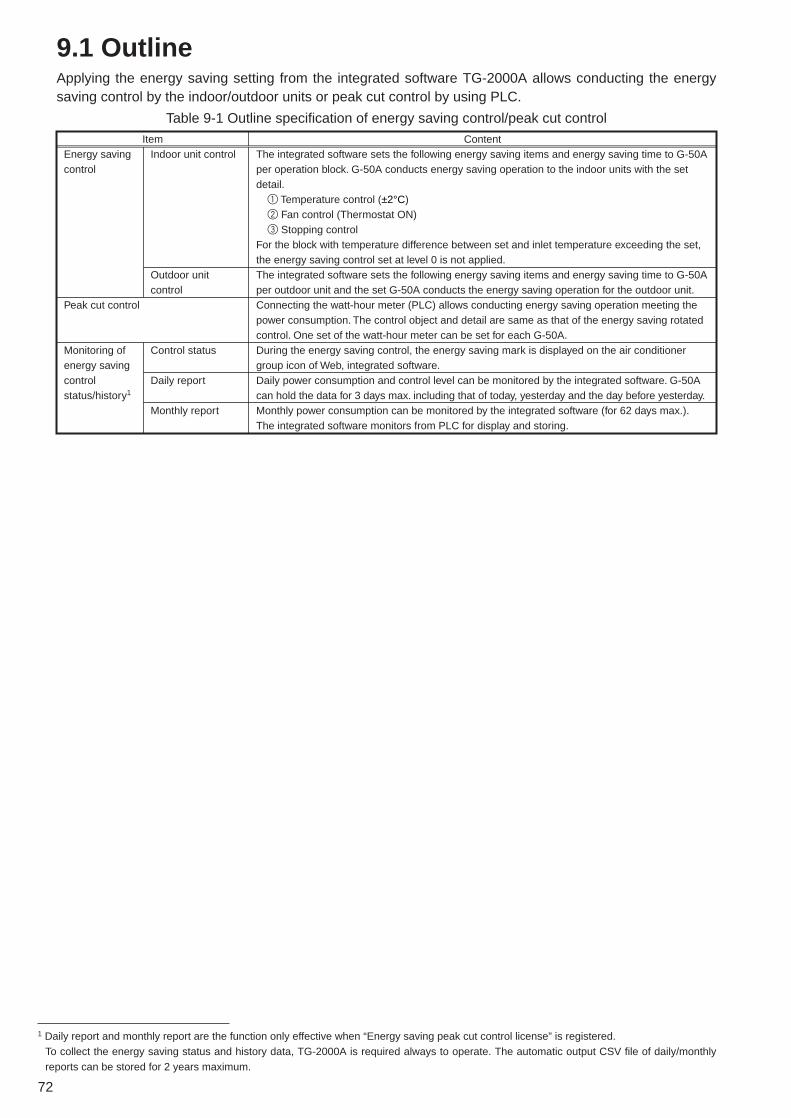
72
9.1 OutlineApplying the energy saving setting from the integrated software TG-2000A allows conducting the energysaving control by the indoor/outdoor units or peak cut control by using PLC.
Energy saving control
Indoor unit control
Outdoor unit control
The integrated software sets the following energy saving items and energy saving time to G-50A per operation block. G-50A conducts energy saving operation to the indoor units with the set detail.
1 Temperature control (±2°C)2 Fan control (Thermostat ON)3 Stopping control
For the block with temperature difference between set and inlet temperature exceeding the set, the energy saving control set at level 0 is not applied.The integrated software sets the following energy saving items and energy saving time to G-50A per outdoor unit and the set G-50A conducts the energy saving operation for the outdoor unit. Connecting the watt-hour meter (PLC) allows conducting energy saving operation meeting the power consumption. The control object and detail are same as that of the energy saving rotated control. One set of the watt-hour meter can be set for each G-50A.During the energy saving control, the energy saving mark is displayed on the air conditioner group icon of Web, integrated software.Daily power consumption and control level can be monitored by the integrated software. G-50A can hold the data for 3 days max. including that of today, yesterday and the day before yesterday. Monthly power consumption can be monitored by the integrated software (for 62 days max.). The integrated software monitors from PLC for display and storing.
Control status
Daily report
Monthly report
Monitoring of energy saving control status/history1
Peak cut control
ContentItem
Table 9-1 Outline specification of energy saving control/peak cut control
1 Daily report and monthly report are the function only effective when “Energy saving peak cut control license” is registered.To collect the energy saving status and history data, TG-2000A is required always to operate. The automatic output CSV file of daily/monthlyreports can be stored for 2 years maximum.

73
9.2 Energy Saving ControlThe energy saving control includes the items listed on Table 9-2, and they can be set from the integratedsoftware for each block freely. After setting, G-50A conducts energy saving control on to the air conditioning group within the operationblock in a unit of 3 (3/6/9/15/30 minutes) within a 30 minutes not allowing overlapping1 the control time.In consideration of comfort, it can be set not to apply the set energy saving control2 to the block of whichtemperature difference between the set and inlet temperature exceeds the temperature difference freelyset (3°C ~ 9°C). (Setting of ineffective energy saving control by temperature difference)
Indoor unit
Outdoor unit
Set temperature control
Fan (thermostat OFF) control
Stopping control
Capacity saving control3
Cool/dry: +2°C, Heat: –2°C (No control for fan, auto)* Shifting by ±2°C at control start time, returning to original temp. at control finish.* When set temp. was changed from local remote controller, browser, G-50A unit or schedule
during temp. control, and the temp. value at control finish differed from that at the start, it does not return to the state before the control.
Capacity saving 0% control for Free Plan indoor units and A-control Slim indoor units.Fan operation control for the models before Free Plan.* When the mode was changed from remote controller, browser, G-50A unit or schedule
during fan mode control, and the mode at control finish was that other than fan mode, it does not return to the state before the control.
Stopping outdoor unit* Transmits “STOP” at control start time and returns to the original start/stop state at control
finish.* When the operation was made from local remote controller, browser, G-50A unit or
schedule during stopping control, and the state at control finish was not stopping, it does not return to the state before the control.
The maximum value of outdoor unit operating capacity can be controlled to 60%/70%/80%/ 90% (in 10% unit).
Control detailControl unit Control items
Table 9-2 Energy saving control items
1 The control time may be overlapped depending on the group numbers inside the block and control time.2 Energy saving control is applied at the levels 1 ~ 4 regardless of the temperature difference.3 Controllable only for City Multi air conditioners. (Do not set to Multi-S.)
Setting control detail and timeSelect energy saving control detail and time of indoor unit.
Setting ineffective temp. difference for energy saving controlSet ineffective temp. difference for energy saving control (Ineffective 3 ~ 9°C).
Setting control detail and timeSelect energy saving control detail and time of outdoor unit.
Selecting G-50A for setting targetSelect G-50A objective for
energy saving setting.Batch setting for whole
building is possible.
Selecting indoor unit setting unitSelect block objective for energy
saving control or batch setting for whole building.
Selecting outdoor unit setting unitSelect unit objective for energy saving control or batch setting
for whole building.
Figure 9-2 TG-2000A energy saving control setting screen

74
9.2.1 Energy saving control for indoor unit
For the energy saving control for the indoor unit, select the time portion to be applied to the energysaving control items listed in Table 9-2 from 0/3/6/9/15/30 minutes. By dividing those items by the groupnumbers in the operation block evenly, the energy saving control is applied to the groups starting fromthat with smaller group number in order. When “30 minutes stopping” is being applied to save energy,ON/OFF operation can not be performed by any controller.
Notice
● In the case of the block setting stepped across from TG-2000A to G-50A, only the unit controlled by the G-50A is set as the block on the G-50A.Here each G-50A applies rotation control to each group inside the block.
● When the fan/thermostat OFF control is selected, Free Plan models and A-control Slim models are provided with the thermostat OFF (capacity saving control) command, while K-control models with the fan mode switching.As the mode display of the local remote controller does not change, energy savingcontrol can be performed without the perception of occupants.
● Setting of the energy saving ineffective temperature difference allows not applying the level 0 control to the block with the temperature difference between inlet and set temperature exceeding the set value.
● Operation control from Web browser or TG-2000A provides the screen display of [ON] for 1 minute maximum but not allowing to run the air conditioner.
[In case of the energy saving control of indoor unit for 6 minutes when 5 groups is in one block forexample]
1 Times of rotation:For the control of 6 minutes, 3 minutes control is applied for 2 times (= 6 min./3 min.).
2 Cycles of rotation:From the times of rotation in 1, the cycle of rotation for 30 minutes is to be 15 minutes (= 30min./2 times)
3 Intervals of rotation:From the cycles of rotation in 2, the rotation interval of each group in a block counts for 3 minutes(= 15 min./5 groups). (If indivisible, round it to the nearest whole number.)
0
Group 1
Group 2
Group 3
Group 4
Group 5
3 6 9 12 15 18 21 24 27 30 (min)
Figure 9-3 Example of indoor unit energy saving control

75
9.2.2 Energy saving control for outdoor unit
For the energy saving control for the outdoor unit, select a time portion to be applied to the energysaving control items listed in Table 9-2 from 0/3/6/9/15/30 minutes. By dividing those items by the groupnumbers in the operation block evenly, the energy saving control is applied.1
The rotated operation is applied to the outdoor units starting from that with smaller address.
9.2.3 Required materials
Table 9-3 shows the materials required for energy saving control.
[In case of the energy saving control of 3 outdoor units for 15 minutes for example]
1 Times of rotation:For the control of 15 minutes, 3 minutes control is applied for 5 times (= 15 min./3 min.).
2 Cycles of rotation:From the times of rotation in 1, the cycle of rotation for 30 minutes is to be 6 minutes (= 30 min./5 times)
3 Intervals of rotation:From the cycles of rotation in 2, the rotation interval of each group in a block counts for 2 minutes (= 6 min./3 groups).
302724211815129630 (min)
Figure 9-4 Example of outdoor unit energy saving control
● The capacity saving control is a control to suppress the maximum value of the outdoor unit. Therefore, no energy saving effect can be obtained under the setting to 80% if the operation is conducted with the capacity below 80%.
● In the case of the energy saving control, capacity saving control is applied to the outdoor unit individually. For this reason, be careful that the control will be applied to the indoor unit being not targeted if thegroup setting is made by stepping over the refrigerant system.
● In the case of capacity saving control to the outdoor unit, control for a short time may not provide a normal effect. Control for 30 or 15 minutes is recommended.
● For Multi S, set to “No control” so that the capacity saving control will not be applied to the outdoor units.
CAUTIONTime
Capacity
80%
Capacity value
No energy saving effect
Energy saving effect provided
Table 9-3 Required materialsName (Model name)
PC for TG-2000A
Integrated centralized control software (TG-2000A)Centralized controller (G-50A)Energy saving control licenseWeb monitor license
MakerPC/AT convertible unit
Mitsubishi Electric
Mitsubishi ElectricMitsubishi ElectricMitsubishi Electric
RemarksConfirmed operation of IBM, DELL, Hp Compaq.For PC spec., refer to Table 6-4.Use Ver.4.1 or later.
Use Ver.2.5 or later.Requires for each G-50A.Requires for each G-50A.
1 The control time may be overlapped depending on the group numbers in the block and control time.

76
9.3.1 Power consumption monitoring method
(1) Function
9.3 Peak Cut Control
Connecting the watt-hour meter (PLC) allows conducting the energy saving control of Table 9-2 dividedinto 5 levels (Level 0 ~ Level 4) by estimating the power consumption for 30 minutes.Meantime, the control level is judged with an interval of 1 minute, and the control of higher level isapplied in accordance with the measured power consumption for the past 30 minutes and estimatedvalue.
[How to obtain the estimated value]Estimated value (kW) = Power consumption in the past 5 minutes (kWh)
× 6 (Power consumption for 30 minutes) × 2 (kWh → kW <30 minutes> converted) ----- 1
In Figure 9-5 for example, it is assumed that the control at the energy saving level 1 is being conductedin accordance with [Power consumption for the past 30 minutes].In this occasion, the estimated value after 30 minutes is calculated from [Power consumption for thepast 5 minutes] by Equation 1, it reaches the region of energy saving level 2. In this case, the energysaving control set at the energy saving control level 2 will be carried out.By making the energy saving ineffective temperature difference effective, under the control of Level 0,when the temperature difference between the set and inlet temperature is exceeding 3°C~9°C (able toset in a unit of 1°C), It is possible not to allow conducting the energy saving control set at Level 0 inconsideration of comfort.(The control set at Level 1 ~ Level 4 will be conducted regardless of the temperature difference.)
G- 50A PC for TG-2000A
Collection of information on the daily power consumption
Collection of informationon the current minute-by-minute power consumption
Energy-saving control (peak cut)Registration of license
(60/70/80/90%)
·Setting the energy-saving control items·Setting the level of energy-saving control
·Monitoring the current energy-saving status
·Controlling the set temperature(±2˚C)·Fan (Thermo OFF) control ·Stop control
Judgment of energy-saving control level
Capacity control
PLC (Electric Amount Count Software) Counting the electric pulse
Watt-hourmeter
Figure 9-5 Configuration of the system using the power consumption monitoring method

77
Setting control detail and timeSelect the detail and time of indoor unit peak cut control.
Setting energy saving ineffective temperature differenceSet the detail and time of energy saving ineffective temperature difference.
Setting the detail and time of controlSelect the detail and time of outdoor unit peak cut control at each level
Selecting target G-50A for setting
Select G-50A objective for peak cut setting.
Batch setting for whole building is possible.
Setting levelsSet the electric power to start
peak cut control. (Levels 1 ~ 4)
Selecting the setting unit of indoor unit
Select indoor unit objective for peak cut control or select
whole building collectively.
Selecting the setting unit of outdoor unit
Select outdoor unit objective for peak cut control or select
whole building collectively.
Figure 9-7 TG-2000A peak cut control setting screen
● For Multi S, set to “No control” to prevent conducting the capacity saving control.CAUTION
By setting the target demand value and [Stopping control for 30 minutes] of the energy saving controlitem, the peak cut control can be practiced as an application of the level control above.
(2) Required materials
The materials required for the peak cut control are shown in Table 9-4.
Table 9-4 Required materials for peak cut control
Name (Model name)PC for TG-2000A
Integrated centralized controlsoftware (TG-2000A) Centralized controller (G-50A)Peak cut control licenseWeb monitor licensePLC
Pulse counting software
(PAC-YG11CDA, etc.)
MakerPC/AT convertible unit
Mitsubishi Electric
Mitsubishi ElectricMitsubishi ElectricMitsubishi ElectricMitsubishi Electric
Mitsubishi Electric
RemarksConfirmed operation of IBM, DELL, Hp Compaq.For PC spec., refer to Table 6-4.Use Ver.4.1 or later.
Use Ver.2.5 or later.Requires for each G-50A.Requires for each G-50A.Usable commonly with PLC for measuring instrument charging.For detail, refer to Table 8-4. Use Ver.1.01 or later for peak cut control.
Power consumption for past 30 minutes
Power consumption for past 5 minutes
Level 2
Level 1
Estimated power consumption after 30 minutes
Estimated mean power consumption for 30 minutes
Estimation of mean electric power for 30 minutes (demand value)
Before 5 minutes
Present
10kWh
120kW
1kWh2kWh
3kWh
30 minutes
120kW
Figure 9-6 Level estimation

78
9.3.2 Peak Cut Control by Demand Controller
(1) FunctionA peak cut control can be performed by the use of demand level signals from the demand controller.Demand level signals from the demand controller are input with the use of PLC (PLC software fordemand input).Up to 4 levels of demand level signals from the demand controller can be input, and 5 levels (level 0 –level4) of energy-saving control can be set as shown in figure 9-2.
G- 50A PC for TG-2000A
·Controlling the set temperature(±2˚C)·Fan (Thermo OFF) control ·Stop control
Registration of the energy-saving control license (peak cut) is necessary.
·Energy-saving setting·Daily report monitor
Contact input (4 levels max.)
(60/70/80/90%)
·Capacity controlSends a report on the demand control level
PLC (PLC software for demand input)
Demand controller
Figure 9-8 Configuration of a system with a demand controller
Control with the use of demand level signals is performed as the following.Refer to section 4.3 for information on connecting the controller to the DI board on the PLC.
Demand controller
PLC DI board (QX40)
Level 1
Level 1 Level 1Level 2 Level 3 Level 4Level 0 Level 0
Level 2
Level 3
Level 4
Figure 9-9 Demand Level Operation
● Because the energy-saving control on G-50A is performed once per minute, the change does not take place immediately when the level of demand controller is changed.
● Lower the judgment value setting for the demand controller’s control level as necessary.
● While G-50A or the equipment connected via LAN are experiencing problems or during a power outage, energy-saving control will not function.
● When PLC is experiencing a problem, the last demand level before the start of the problem will be maintained.
CAUTION

79
(2) Necessary MaterialsTable 9-5 shows a list of necessary materials to run a demand controller operation.
Table 9-5 Necessary materials to run a demand controller operation
Materials (model)Computer for TG-2000A
Integrated centralized controlsoftware (TG-2000A)Centralized controller (G-50A)Web monitor licenceEnergy-saving control (peak cut) licenseSequencerPLC software for demand input(PAC-YG41CDA etc.)
MakePC/AT compatible
Mitsubishi Electric Corp.
Mitsubishi Electric Corp.Mitsubishi Electric Corp.Mitsubishi Electric Corp.Mitsubishi Electric Corp.Mitsubishi Electric Corp.
RemarksTested and confirmed to run on IBM, DELL, and COMPAQRefer to Table 6-4 for computer specifications.Version 4.60 or later
Version 2.6 or laterRequired for every G-50A unitRequired for every G-50A unitRefer to Table 4-12 for sequencer (PLC) specificationRefer to Table 4-11 for details.

80
Notice ● When status is monitored, only the air conditioning group under energy saving controlwill have icons displayed as shown in the Table 9-5.
● Power saving control of outdoor units will not make the energy saving symbol displayedwith air conditioning group icon, since it is unknown whether the outdoor unit has energysaving operation at that point in time.
● During level 0 control, if a difference between the target temperature and air intaketemperature is ineffective for energy saving, energy saving will not be executed and therewill not be an energy saving control icon on the display.
● Daily and monthly reports<Automatic output file>The automatic output file is automatically created daily (or monthly) as TG-2000Agathers information from G-50A and PLC. Therefore it is not created if TG-2000A isfinished.<Manual output file>You can manually output each file from the TG-2000A tool bar. Monthly data will becreated from TG-2000A database while daily data for the day, the day before andtwo days before will be collected from G-50A. (The data earlier than that will be created from TG-2000A database.)
CAUTION
9.4 Energy Saving Control Status ·History Monitor
9.3.1 Current energy saving control Status
You can confirm whether or not an air-conditioning group is under energy saving control. If energy savingcontrol is on, operation status icons shown below will be indicated on the display by the web browser orintegrated software.
9.3.2 Peak cut status history
From the menu bar in the TG-2000A control screen, select [tool]-[peak cut data] and you will be able tooutput peak cut status history daily report and monthly report as a CSV file.1
The daily and monthly report files will automatically be stored in the automatic trend output folder2 for twoyears.
(1) Peak cut status history (daily report)
Control level at every one minute and power consumption data by the unit of 30 minutes can be outputas a CSV file. The daily report can be selected and output up to 31 days (Maximum) retroactively.
(2) Peak cut status history (monthly report)
Power consumption data per day can be output as a CSV file. The monthly report can be selected and output for the past 62 days (Maximum) retroactively.
Table 9-5 Energy saving control icons
Set temperature control or fan control is on.* In case or a pre-scheduled operation or an interlocked unit connection, those icons will also be displayed.
Stopping control is on. * In case or a pre-scheduled operation or an interlocked unit connection, those icons will also be displayed.
1 When TG-2000A is stopped or unable to communicate, data may not be obtained due to the lack of monitor collection.2 The automatic trend output folder can be set freely. For detail, refer to “14.2 Trend data output.”

81
(3) Creation of daily report/monthly report trend graphs
You can turn a CSV file (trend graph) into a graph using “Trend graph Idisplay tool” that comes with TG-2000A. Refer to the Item 14.2 for details.
Figure 9-7 Peak cut status history daily report example

82
9.5 Peak Cut Control: Example
9.5.1 A room with multiple air conditioning groupsIn the following graphs, the effects of different types of peak cut control and the changes in temperaturethat are observed in a room with multiple air conditioning units (air conditioning units) are shown.With a room with multiple air-conditioning unit groups, energy-savingcontrol will not be performed on all units simultaneously; therefore, evenwith 6-minute-thermo-off control, the temperature rise is kept around 2˚C.
* The graphs below show an example of the peak cut control. Theactual effects of peak cut control and temperature change will vary ineach situation.
* In the example below, the amount of energy saved is calculated byassuming that the average power consumption before and after theenergy-saving time zone equals the amount of energy consumptionwithout a peak cut control.For example, in the case of 3-minutes thermo OFF, the amount ofpower that the unit would consume without the energy-saving controlis calculated as (140 + 130 ) / 2 = 135kW.
Number of outdoor units : 20 unitsNumber of indoor units : 84 unitsRated poer consumption : 189.8kW
Points of measurement
No change in room temperature
No change in room temperature
No energy-saving control
9-minutes thermo OFF6-minutes thermo OFF
3-minutes ± 2˚C
6-minutes ± 2˚C
3-minutes thermo OFF
Energy-saving time zones
13:30 ~ 14:0014:30 ~ 15:0016:00 ~ 16:30
Energy-saving time zones
:14:00 ~ 14:3015:30 ~ 16:00
142→134kWApprox. 6%decrease
135→122kWApprox. 10%decrease
137→92kWApprox. 33%decrease
145→108kWApprox. 26%decrease106→96kW
Approx. 9%decrease
Settemperature
Room temperature
Approx. 2˚C riseApprox. 1˚C rise
Approx. 3˚C rise
:
Energy-saving time zones
13:30 ~ 14:0015:00 ~ 15:30
: Energy-saving time zones
13:30 ~ 14:0014:30 ~ 15:00
:Energy-saving time zones
13:30 ~ 14:0014:30 ~ 15:00
:

83
9.5.2 Room with a single air conditioning group
In the following graphs, the effects of different types of peak cut control and thechanges in room temperature that are observed in a room with a single airconditioning unit (air conditioning group) are shown.With a single air conditioning system, the effect on the room temperature isgreater when a peak cut control is performed, and the level of comfort will dropmore sharply compared to a room with multiple air conditioning groups runningunder the same type of control.
Energy-saving time zones
: 13:30 ~ 14:0014:30 ~ 15:0016:00 ~ 16:30
Energy-saving time zones
: 13:30 ~ 14:0015:00 ~ 15:30
Energy-saving time zones
: 13:30 ~ 14:0014:30 ~ 15:00
135→122kWApprox. 10%decrease
137→92kWApprox. 33%decrease
145→108kWApprox. 26%decrease
Approx. 1˚C rise Approx. 3˚C rise
Approx. 5˚C rise
Settemperature
Room temperature
No energy-saving control
9-minutes thermo OFF
3-minutes thermo OFF 6-minutes thermo OFF
Points of measurement

84
9.6 Steps in setting up an energy-saving control systemThe following are the steps to be taken to execute an energy-saving control plan.
(1) Deciding on the means of energy-saving control.
Decision is made regarding the means of energy-saving control.Energy-saving control regardless of power consumption – Power-saving controlEnergy-saving control in proportion to power consumption – Peak cut control
(Power consumption monitoring method)Energy-saving control with the use of demand controller – Peak cut control
(demand controller method)
(2) Necessary Materials.
Prepare the materials necessary for a given energy-saving control system.
(3) Deciding on the level of energy-saving control
Five levels of control to perform the peak cut control wIll need to be set.Take into consideration the current contract demand and target contract demand, and determine thehighest level (level 4). Then determine each of the remaining levels.
[Example] In the case where target contract demand is 100 kW.Level 4: 85 kW ~ Level 3: 75 kW ~ 85 kWLevel 2: 65 kW ~ 75 kWLevel 1: 55 kW ~ 65 kWLevel 0: ~ 55 kW
(4) Select the energy saving control method.
As an energy saving control method, you choose either [energy saving control using indoor units] or[energy saving control using outdoor units], or both. [Example] Use both indoor unit energy saving control and outdoor unit energy saving control.
(5) Confirm the energy saving area.
The energy saving control of indoor units is done through a rotation control of the group operationbased on the unit of operation block. The energy saving control of outdoor units is done by rotating theoperation of the outdoor unit in numerical order of the address. The control order is sequenced from asmaller number given to the group. First, you confirm the order of control within the operation block.[Example] In the figure shown on the right, Group 1 to Group 6
belong to the same operation block (Office A). In thiscase, Group 1 and Group 2 on the window side will becontrolled consecutively. Compared with the Group 5and Group 6 side of the room, the temperature in thewindow side goes up temporarily (in summer). By rearranging the groups you can provide energysaving control without too much sacrificing comfort.In this case, Group 4 should become Group 2, Group5 should become Group 3, Group 2 should becomeGroup 4, and Group 3 should become Group 5. Bydoing so, you can avoid two window side units havingenergy saving control at the same time and improvethe comfort level. Office A
Group 1 Group 2
Outdoor
Group 5 Group 6
Group 3 Group 4
Determine the value for each rectangle space on theleft that corresponds to each of the 4 levels.The values need not be set for a system running onthe demand controller method or E-Energy method,because control is performed by means of the levelsignals they use.

85
(6) Control settings
Make appropriate control settings for the control block and for each outdoor unit. To run an energy-saving control on both indoor and outdoor units at the same level, make a setting for each unit.[Example] In the case where target contract demand is 100 kW.
Level OfficeA Outdoor unit 51Level 4: 85 kW ~ 30 minutes Stop 30 minutes Capacity saving 60%Level 3: 75 kW ~ 85 kW 6 minutes Fan control 30 minutes Capacity saving 70%Level 2: 65 kW ~ 75 kW 3 minutes Fan control 30 minutes Capacity saving 80%Level 1: 55 kW ~ 65 kW 3 minutes Fan control 30 minutes Capacity saving 80%
Level 0: 0 kW ~ 55 kW 3 minutes Temperature 0 minutes N/Acontrol
Advantages and disadvantages of various types of control.
Settings for a large room, shared area, and small roomNot all of the air conditioning units installed in a large room will be controlled by the energy-savingcontrol at the same time because they will be on a rotation. Therefore, make the energy-saving settingsrelatively high. The same is true for such places as hallway and elevator halls where they are notoccupied with people at all times.For a small room with only one group of air conditioners, keep the energy-saving setting small tominimize the effect of energy-saving control on the room temperature.
Indo
or u
nits
Out
door
un
its
Items Advantages·Although not as energy-saving as other types of control, it is capable of maintaining comfortableness in the room.
·The fact that the unit is running an energy-saving operation does not show on the remote controller ; thus, it can be kept away from the users.
·Energy saving effect can surely be obtained.·Energy saving effect can surely be obtained.
·The fact that the unit is running an energy-saving operation does not show on the remote controller ; thus, it can be kept away from the users.
Disadvantages·Not very energy-saving when room temperature is high (When the set temperature is 23˚C and the room temperature is 29˚C, no effects of energy-saving control can be expected when the set temperature is changed from 23˚C to 25˚C.)
·The changes in the set temperature are indicated on the remote controller, so the users will know if the unit is running an energy-saving operation.
·Although solidly energy-saving, the level of comfortableness in the room may be compromised.
·Although solidly energy-saving, the level of comfortableness in the room may be compromised.
·Because the unit makes periodical stops, it tends to be mistaken that the unit is having problems.
·When running below the capacity saving value set by the outdoor unit, energy-saving effect cannot be expected.
Recommended
Temperature control(Set temperature ±2˚C)
Fan control (Thermo OFF)
Stop control
Capacity saving
1
2
● For control level four, choose a setting that will certainly lower the power consumption.Example: Stop, Thermo OFF
CAUTION
Level 4Level 3Level 2Level 1Level 0
Stop controlFan controlFan controlFan controlNo setting
30 minutes 6 minutes 3 minutes 3 minutes -
60%70%80%80%
No setting
30 minutes30 minutes30 minutes30 minutes -
Indoor unit control setting Outdoor unit control setting
All air conditioners stopped
May be set
Level 4Level 3Level 2Level 1Level 0
Stop controlFan controlNo settingNo settingNo setting
30 minutes 3 minutes - - -
60%70%80%80%
No setting
30 minutes30 minutes30 minutes30 minutes -
Indoor unit control setting Outdoor unit control setting
All air conditioners stopped
May be set
<Settings for a large room or shared area : Example>
<Settings for a small room : Example>
1 When running a fan control, the operation mode on older models (K control units etc.) except the free-plan units will beswitched to “Fan” and the remote controller will indicate “Fan.” For the free-plan models, it will go into thermo OFF (breeze)and there is no change on the remote controller display.
2 If [30 minutes][Stop] are selected, operation from the remote controller will be prohibited while the demand level is maintainedresulting in solid peak cut.
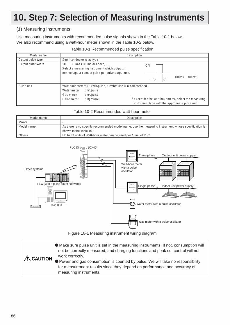
86
10. Step 7: Selection of Measuring Instruments(1) Measuring instruments
Use measuring instruments with recommended pulse signals shown in the Table 10-1 below.We also recommend using a watt-hour meter shown in the Table 10-2 below.
● Make sure pulse unit is set in the measuring instruments. If not, consumption will not be correctly measured, and charging functions and peak cut control will not work correctly.
● Power and gas consumption is counted by pulse. We will take no responsibility for measurement results since they depend on performance and accuracy of measuring instruments.
CAUTION
Table 10-1 Recommended pulse specificationModel name
Output pulse typeOutput pulse width
Pulse unit
DescriptionSemi-conductor relay type100 ~ 300ms (100ms or above)Select a measuring instrument which outputs non-voltage a-contact pulse per pulse output unit.
Watt-hour meter : 0.1kWh/pulse, 1kWh/pulse is recommended.Water meter : m3/pulseGas meter : m3/pulseCalorimeter : MJ/pulse * Except for the watt-hour meter, select the measuring
instrument type with the appropriate pulse unit.
ON
100ms ~ 300ms
Table 10-2 Recommended watt-hour meterModel name
MakerModel name
Others
Description-As there is no specific recommended model name, use the measuring instrument, whose specification is shown in the Table 10-1. Up to 32 units of Watt-hour meter can be used per 1 unit of PLC.
Gas meter with a pulse oscillator
PLC DI board (QX40)
TG-2000A
Other systems
PLC (with a pulse count software)
Three-phase
Watt-hour meter with a pulse oscillator
Outdoor unit power supply
Single-phase Indoor unit power supply
Water meter with a pulse oscillator
Figure 10-1 Measuring instrument wiring diagram
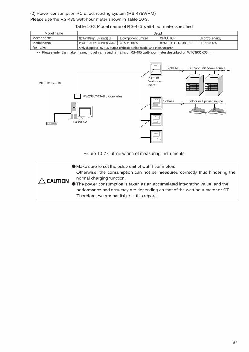
87
(2) Power consumption PC direct reading system (RS-485WHM)Please use the RS-485 watt-hour meter shown in Table 10-3.
● Make sure to set the pulse unit of watt-hour meters.Otherwise, the consumption can not be measured correctly thus hindering thenormal charging function.
● The power consumption is taken as an accumulated integrating value, and the performance and accuracy are depending on that of the watt-hour meter or CT. Therefore, we are not liable in this regard.
CAUTION
Table 10-3 Model name of RS-485 watt-hour meter specified
Model nameMaker nameModel nameRemarks
<< Please enter the maker name, model name and remarks of RS-485 watt-hour meter described on WT03901X03.>>
Detail
Northern Design (Electronics) Ltd.POWER RAIL 323 + OPTION ModuleOnly supports RS-485 output of the specified model and manufacturer
Elcomponent LimitedAEM31D/485
CIRCUTORCVM-BC-ITF-RS485-C2
Elcontrol energyED39din 485
TG-2000A
Another system
RS-232C/RS-485 Converter
3-phase
RS-485Watt-hour meter
Outdoor unit power source
1-phase Indoor unit power source
Figure 10-2 Outline wiring of measuring instruments

88
11. Step 8: General Purpose Equipment ControlTG-2000A can control and monitor system equipment that are connected to the PLC and indoor unit freecontact1. The general-purpose control function enables the operation of the air conditioners by interlockingthem with other equipment. By using general-purpose control functions, you can control and monitor other manufacturer’s airconditioning units, lighting fixtures and other system equipment as well as water level of a water or fire tankwith a flooding/low level alarm on the TG-2000A monitor screen. Or the interlocked air conditioners can bestopped by removing the card key. System equipment is controlled by PLC. “General-purpose control software: PAC-YG21CDA” needs to beinstalled in PLC. (For PAC-YG21CDA Ver.1 series, no licensing registration needed for G-50A.)
● Operation and monitoring of general purpose system equipment cannot becontrolled if the PLC or other equipment fails. Take this into consideration, andmake sure you provide a circuit for a switch for an emergency stop/start. Do notuse it for monitoring the system affecting human life. In case you do, incorporatean alternative safety mechanism.
● Do not use this system for fire prevention or for security purposes. Above all, donot use the system where lives of people are at risk. Use other means ofmonitoring methods.
CAUTION
To other systems
To DI/DO board
PLC (PLC software for
general-purpose equipment)
TG-2000A
G-50A General purpose system equipment
To free contact point terminal
Air conditioners interlocking control
Free contact point status report
Indoor units
Lighting
Other manufacturer’s packagedair-conditioning units
Other manufacturer’s fan coil units
Chiller/heat source machine
Card key
General-purpose equipment
Status monitor for general-purpose equipment
Figure 11-1 Configuration of the general-purpose control system
1 Free contact point may be used by R410a compatible indoor units or R407C compatible indoor units (S/W version 33 or later).Check the S/W version of the indoor units with the maintenance tool.

89
11.1 OutlinePLC will be used to control general equipment, along with a DI board (DC input unit) and a DO board(transistor output unit). One icon will be shown on the TG-2000A monitor screen to represent one system equipment, and you canoperate (one shot pulse or level output), monitor the status, and monitor for error (level input). Therefore, you will be using two terminals on DO board and two terminals on DI board for one systemequipment. For status monitoring, you can choose the name of the status, and for error status, you can choose thename of the error and its icon color.
11.2 System Design MethodSystem design method for general-purpose control is outlined below.
11.2.1 Listing up of general equipment
General equipment needs to be listed up. Control and monitoring of general equipment will be done through contact control using PLC. Therefore,the equipment to be controlled should have the following signal specifications. TG-2000A can only operateor only monitor the equipment, in that case, unused terminals should remain unconnected.
Table 11-1 General-purpose control signal specifications
Operation
Monitoring
Signal specifications
Non-voltage a-contactOne shot pulse output
Non-voltage level input
Terminal assignment/equipment1
2 terminals
2 terminals
Contact specifications
Signal 1 (operate)
According to the setting (Default 1 second)
According to the setting (Default 1 second)
Contact ON
Contact OFF
Contact ON
Contact OFFSignal 2 (stop)
Signal 1Contact ON
Contact OFF
Contact ON
Contact OFFSignal 2
Stop Run Stop
Stop Run Stop
Normal Error/trouble Normal
Run
Stop
1P
1P
Systemequipment 1
PLC DO board (QY40P)
PLC DI board (QX40)
One shot pulse output signal
You can control and monitor one system equipment with one icon.
Level input signal
Control
Operation status
Error status
1P
1P
Monitoring
Figure 11-2 General-purpose control outline
1 Number of terminals assigned to one system equipment

90
11.2.2 Determine the control items.
After you determine the equipment to be connected, define the control items for each equipment. For instance, whether you want to operate the instrument (ON and OFF) and monitor it, including errormonitoring, or just watch for failure (malfunction). For ON and OFF, status output signal from theinstrument changing the icon status (color) is the basic1 mechanism.
*When the system instrument does not provide the output of operation status, connect to the input of operation status by installing a self-holding circuit.
The error signal from the system instrument will turn this to the error status display.
If the status is OFF, operate and send the ON signal from the system instrument. The status will change to ON.
PLC DO board (QY40P)
PLC DI board (QX40)
ON
OFF
Operation status
Error status
Operation
Monitoring
System instrument
1P
1P
1P
1P
Error signal from instrument will change it to error status display.
PLC DO board (QY40P)
PLC DI board (QX40)
Not in use
Not in use
Not in useError status
Monitoring
System instrument
1P
ON/OFF output signal terminal will have no connection.
Status signal input terminal will have no connection.
1 We recommend that you connect the status signal from the instrument.If the status signal is not connected (judgment only from the operation), there might be a discrepancy between the instrument operation statusand the icons on TG-2000A display.
Application example 1: ON/OFF operation, status monitoring, and error monitoring(Basic example)
Application example 3: Error monitoring only

91
11.2.3 PLC assignment
After you determine the control items of the connected instrument, assign PLC terminals.PLC for general equipment needs to have one DI board and one DO board mounted regardless of thecontrol items. (There are certain restrictions about the mounting location and others. Refer to 12.3 fordetails.)Table 11-3 shows the PLC terminal assignment. Since each terminal in PLC has a pre-determinedfunction, keep the terminal un-connected (open) where the signal is not to be used.
11.2.4 Required materials
Members required for general-purpose control are listed in the Table 9-3.
Table 11-2 PLC for general equipment restrictions����
������ ����� � ��������� �� � � � ��
�������� � �� ���
������ ��� � ����� � ��������� �� �
� � �� �������� � ��������
�� ������ ������� � ��� � ��� � ����� �
���������
������
�� � ����� !"��#$%
�� � &� ����� !"��#�%
�� �����
$'�#$( #$#$)$ * $'�#$( #$#$'�
+�� �,�
!"��#$% ����� ��� ������ ��� ����� �����
&� !"��#�% ����� ��� ������ ��� ����� �����
������ ����� �������� ���������
- $(� !"��#$%. (/� !"��#�%
+��������� ������� � ��� �� ��0�#
Table 11-3 PLC for general equipment terminal assignment
Control equipment number
General equipment 1General equipment 2General equipment 3General equipment 4General equipment 5General equipment 6General equipment 7General equipment 8
General equipment 31General equipment 32
DO board
General equipment 1 ON signalGeneral equipment 1 OFF signalGeneral equipment 2 ON signalGeneral equipment 2 OFF signalGeneral equipment 3 ON signalGeneral equipment 3 OFF signalGeneral equipment 4 ON signalGeneral equipment 4 OFF signalGeneral equipment 5 ON signalGeneral equipment 5 OFF signalGeneral equipment 6 ON signalGeneral equipment 6 OFF signalGeneral equipment 7 ON signalGeneral equipment 7 OFF signalGeneral equipment 8 ON signalGeneral equipment 8 OFF signal
General equipment 31 ON signalGeneral equipment 31 OFF signalGeneral equipment 31 ON signalGeneral equipment 32 OFF signal
DI board
General equipment 1 operation status signalGeneral equipment 1 error status signalGeneral equipment 2 operation status signalGeneral equipment 2 error status signalGeneral equipment 3 operation status signalGeneral equipment 3 error status signalGeneral equipment 4 operation status signalGeneral equipment 4 error status signalGeneral equipment 5 operation status signalGeneral equipment 5 error status signalGeneral equipment 6 operation status signalGeneral equipment 6 error status signalGeneral equipment 7 operation status signalGeneral equipment 7 error status signalGeneral equipment 8 operation status signalGeneral equipment 8 error status signal
General equipment 31 operation status signalGeneral equipment 31 error status signalGeneral equipment 32 operation status signalGeneral equipment 32 error status signal
Terminal board number
12345678910111213141516
13141516
DI/DO board number
1111111111111111
4444
····
····
····
····
····
Table 11-4 General-purpose control required itemsMaterials (model names)
PC for TG-2000A
Integrated centralized control software (TG-2000A)Web monitor licensePLCPLC software for general equipment(PAC-YG21CDA)
“PLC for general equipment” license
MakerPC/AT compatible
Mitsubishi Electric
Mitsubishi ElectricMitsubishi ElectricMitsubishi Electric
Mitsubishi Electric
RemarksVerified the performance of IBM, DELL, and Hp Compaq.Refer to Table 6-4 for the PC specification.Use Ver. 4.6 or later version.
Requires for each G-50A.Make sure DI board and DO board are mounted.This software should be installed in PLC. The software is different depending on IP address. IP address needs to be designated. (Standard: 192.168.1.171)Use version 2.0 or later.Required for each interlocked G-50ANot necessary when an interlocking setting on the air conditioner is not made.

92
11.2.5 Setting of TG-2000A
After the assignment of terminals, TG-2000A should be configured. For each general equipment, what tobe controlled and monitored should be set up in TG-2000A. Operation/stop schedule1 for the generalequipment can be set on the TG-2000A.
Number of connected PLC’sThis shows how many PLC’s are connected.
Number of general equipmentThis shows how many general units are connected.
Function displayThis shows the functions of the configured general equipment.
Error/alarm status display settingWhether to have an error display for the general equipment will be set and display text will be selected.
General equipment buttonSettings of the general
equipment can be made. Menu includes
change/copy/paste.
Selection of PLC No.Select the PLC.
Selection buttonSelect whether there
is a general equipment or not.
General equipment addressGeneral equipment
address is indicated.
Equipment name settingSet up the equipment name.
(short name, long name)
Operation settingOperation/settings of the general
equipment will be made.
Operation display settingSet the operation display of the
general equipment.
* Display text is changeable.This one screen uses two each of DI and DO board terminals on PLC.
• Whether there is adisplay or not
• Selection of update
Figure 11-3 TG-2000A general equipment registration screen
Notice● General equipment name can be maximum 20 characters. (Short name is 8 characters.)● ON, OFF, error displays are maximum 8 letters.● [ ’ ] (single quotation mark) cannot be used in names and display texts.
1 Only the general equipment connected to the input-output unit of the PLC can be scheduled on the TG-2000A.

93
11.2.6 System planning for the general equipment to be connected to the free contact point on the indoor unit
(1) Indoor unit selection and switch setting method
In order to monitor and control general equipment connected to the free contact point on the indoor unit,choose an R410A-compatible indoor unit.1In order to make the function of the free contact point effective, set the dipswitch (SW1) as the followingwhile the unit is stopped.
Indoor unit SW1Function
Free contact point function is effective(Auto-recovery after power failure)Free contact point function is effective(Normal operation (remains stopped after power restoration))
Contact point specifications
No.5 No.9 No.10
ON ONON
ONONOFF
Signal specifications
Relay contact point output
Level input with or without voltage
Operation
Monitor
Connector number
Output 1 : CN52-2
Output 2 : CN52-3
Output 3 : CN52-4
Input 1 : CN32-2
Input 2 : CN32-3
Input 3 : CN51-2
Input 4 : CN52-5
Output OFF Output ON Output OFF
Input OFF Input ON Input OFF
Contact point ON
Contact point OFFOutput signal 1~3
Contact point ON
Contact point OFFInput signal 1~4
Table 11-5 Indoor unit dipswitch setting to activate the free contact point
(2) Verifying the input/output specifications of the general equipment
Confirm the general equipment to be connected to the free contact point on the indoor unit.Those general equipment to be controlled must be able to handle the following signals becausecontrolling and monitoring of the equipment is performed via the connected indoor unit.
Table 11-6 Specifications for general-purpose control signals (free contact point)
(3) Specifications for free contact point connection
When using input 1 and 2 (CN32), connect a remote maneuvering adapter (PAC-SE55RA) on theindoor unit, and send input signals to the indoor unit via a relay.
Figure 11-4 Free contact (input 1, 2) connection diagram
Y
X
X
Y
CN32
CN32Relay power source SW2
SW2
SW1
X,YSW1
Remote maneuvering adapter(PAC-SE55RA) Indoor unit
controller board
Orange 1
Red 2
Brown 3
Maximum allowable length of wiring is 10 m.
Relay
Switch for input 1 CN32-2 port
Switch for input 2 CN32-3 port
(Contact point: Minimum applied load DC12V 1mA)
1 . Some of the R407C-compatible indoor units also allow free contact connection. Check the software version of the indoor units with the maintenance tool. Free contact point connection can be made to units that came with the software version of 33 or later.

94
When using input 3 (CN51), input 4, output 1, output 2, output 3 (CN52), send input signals to theindoor unit or receive output signals via a relay.
Figure 11-5 Free contact point (input 3, 4, output 1, 2, 3) connection diagram
CN51
CN32
CN52 [Usable input / output] CN51-2 port (Input)
[Usable input/output] CN32-2 port (Input) CN32-3 port (Input)
[Usable input / output] CN52-5 port (Input) CN52-2 port (Output)
CN52-3 port (Output) CN52-4 port (Output) Adapter(PAC-SA88HA)Relay circuitDistant control board
Adapter(PAC-SA88HA)Relay circuitDistant control board
Adapter(PAC-SA88HA)Relay circuitDistant control board
Adapter(PAC-SE55RA)Relay circuitDistant control board

95
(4) Entering the settings on the TG-2000A
Once an arrangement for the free contact points has been completed, enter the setting on the TG-2000A. For each piece of general-purpose equipment to be controlled, enter information on the TG-2000A regarding what is to be monitored and controlled.
Notes
● Equipment connected to the free contact point cannot be set to run on schedule.● Up to 20 characters can be used for the name of general equipment
(8 for short names).● Up to 8 characters can be used to indicate “operation”, “stop”, and “error”.● Single quotation mark cannot be used for the names and other display characters.
Select the equipment for which the settings areto be entered, and open its detailed setting menu.
Select the items to be controlled. Select the free contact point to be
monitored and controlled.
Select the display characters.
Figure 11-6 Setting menu for the TG-2000A general equipment (free contact)

96
11.2.7 Interlocking control settings
Use the table setting tool on PLC software for general equiment Ver.2 to register the interlocking setting onthe PLC in order to control equipment and air conditioners that are connected to the general equipments.
(1) Preparation
Attach an ATA card that has the general control PLC software for general equiment Ver.2 to the ATAcard adapter for PC, and insert it in the card slot on the computer.Install the “Table Setting Tool”1 on the computer.
(2) Determining the interlocking control items
Clarify what kinds of control are to be performed based on the operating condition of the airconditioners or general-purpose equipment that are connected to the PLC free contact spot.Things that can be controlled are the turning on and off of the equipment that are connected to eitherPLC or free contact spots, or operation control of the air conditioners (operation/stop, operation mode,set temperature, fan speed, prohibition of operation).
Input source Output destination
Status change of the general equipment (free contact)
Card keys etc. Indoor unit
Status change of the general equipment (PLC)
Chiller/heat-source equipment
PLC PLC
Air conditioner operation/stop
Air conditioner
Operation of air conditioners
Air conditioner
Indoor unitLighting, ventilating fan, etc.
General equipment (free contact spot) operation/stop
General equipment (PLC) operation/stop
Operation/stop Fan speedOperation mode Prohibition of operationSet temperature
Fan coils etc. by other manufacturers
*If “air conditioner operation/stop” is selected as the input source, “operation of air conditioners ” cannot be selected as the output destination.
Notes
● “Operation/stop” and “Error” on the general-purpose equipment, “Contact point inputOn/Off” on the free contact, and “Operation/Stop” of the air conditioner can be set as theinterlocking source input.
● “Operation/Stop,” “Operation mode,” “Set temperature,” “Fan speed,” “Operationprohibition,” “Interlocked ventilation operation/stop” can be set for the interlocking controlof air conditioners.
● “Operation/Stop” can be set for the interlocking control of general-purpose equipment.● “Contact point output on/off” can be set for the interlocking control of free contact points.
Figure 11-7 Interlocking control, input source, output destination
1 . “Table Setting Tool.” is in the CD of PAC-YG21CDA.

97
(3) Setting the content of the interlocking control
Start the “Table Setting Tool,” and enter the content of the interlocking control.After entering the content of the control, store the setting on the ATA card, insert the ATA card into thePLC, and start up.
Set up the input source (interlocking source).
Link the input and output sources.
Set up the output destination (interlocking destination).
Figure 11-8 “Table Setting Tool” setting menu
(4) Registration of the IP address and license of the controller G-50A
When air conditioners are selected as the output destination, change the IP address of the G-50A towhich the air conditioners are connected from TG-2000A to PLC.Also when air conditioners are used as the input source or output destination, register the “PLC forgeneral equipment” license for the G-50A to which the air conditioners are connected.

98
11.3 Notes on using the general equipment control function
Note the following when using the general equipment control function.
(1) Notes on set up
●● Do note use the control function for fire prevention or for security purposes. Never use it in the waythat would put people’s lives at risk.
●● Up to 32 pieces of equipment can be controlled by one PLC.●● Up to 20 general control PLC can be connected to a TG-2000A. (up to 640 pieces of general
equipment).●● Interlocking control of up to 2 G-50As (up to 100 air conditioning units) by each PLC is possible.●● When running an interlocking control, up to 200 input sources can be selected from PLC contact
points, free contact points, air conditioning operation/stop.●● When running an interlocking control, the operation status of the air conditioning cannot be used as
an input source to operate the air conditioners.
(2) Notes on Restrictions
●● The system may not operate properly if the power to any connected equipment is not turned on or ifthere is a problem with any of the connected equipment.
●● Depending on the status of the system, it may take some time for the control operation to go intoaction..
●● Be sure to reset the PLC if there is a change in the configuration of the G-50A air conditioning groupconnections.
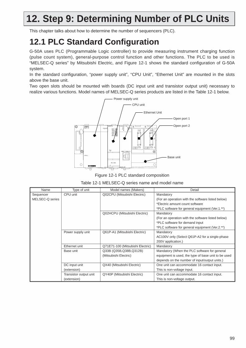
99
12. Step 9: Determining Number of PLC UnitsThis chapter talks about how to determine the number of sequencers (PLC).
12.1 PLC Standard ConfigurationG-50A uses PLC (Programmable Logic controller) to provide measuring instrument charging function(pulse count system), general-purpose control function and other functions. The PLC to be used is“MELSEC-Q series” by Mitsubishi Electric, and Figure 12-1 shows the standard configuration of G-50Asystem. In the standard configuration, “power supply unit”, “CPU Unit”, “Ethernet Unit” are mounted in the slotsabove the base unit. Two open slots should be mounted with boards (DC input unit and transistor output unit) necessary torealize various functions. Model names of MELSEC-Q series products are listed in the Table 12-1 below.
Table 12-1 MELSEC-Q series name and model name
NameSequencerMELSEC-Q series
Type of unitCPU unit
Power supply unit
Ethernet unitBase unit
DC input unit (extension)Transistor output unit (extension)
Model names (Makers)Q02CPU (Mitsubishi Electric)
Q02HCPU (Mitsubishi Electric)
Q61P-A1 (Mitsubishi Electric)
Q71E71-100 (Mitsubishi Electric)Q33B (Q35B,Q38B,Q312B) (Mitsubishi Electric)
QX40 (Mitsubishi Electric)
QY40P (Mitsubishi Electric)
DetailMandatory(For an operation with the software listed below)*Electric amount count software*PLC software for general equipment (Ver.1.**)Mandatory(For an operation with the software listed below)*PLC software for demand input*PLC software for general equipment (Ver.2.**)MandatoryAC100V only (Select Q61P-A2 for a single-phase 200V application.)MandatoryMandatory (When the PLC software for general equipment is used, the type of base unit to be used depends on the number of input/output units.)One unit can accommodate 16 contact input. This is non-voltage input.One unit can accommodate 16 contact input. This is non-voltage output.
Base unit
Power supply unit
CPU unit
Ethernet Unit
Open port 1
Open port 2
Figure 12-1 PLC standard composition

100
12.2 Connection method for a system with a charging function or peak cut control function
12.2.1 Restriction on the number of units
To carry out measuring instrument charging function or energy saving peak cut control1, you will need tohave the standard configuration explained in the previous chapter plus a DC input unit.One DC input unit can support 16 contacts, so you can connect up to 16 measuring instruments. Sinceone PLC has two open ports, you can connect 32 watt-hour meters to 2 DC input units. In case 33 or morewatt-hour meters have to be connected, add one more PLC unit.
PLC standard composition(Electric amount count software)
PLC5
PLC2
PLC1
TG-2000A
Up to 5 PLC units can be connected to TG-2000A. (Total number of watt-hour meters is 160 at maximum.)
Up to 16 watt-hour meters can be connected to 1 DC input unit.
2 DC input units can be connected to 1 PLC unit. (Total number of watt-hour meters is 32 at maximum.)
Figure 12-2 Restriction on the number of PLC units for the electric power apportioned charge function
12.2.2 Terminal connection diagram
Connection to DC input unit (QX40) terminals is shown in the Figure 12-3. (For wiring example, refer to 12.6)Since DC input unit is non-voltage input, you need to prepare an external DC24V power supply (DC12V iscannot be used).
Measuring instrument wiring
Measuring instrumentwith a pulse oscillator
Measuring instrumentwith a pulse oscillator
Measuring instrumentwith a pulse oscillator
DC24V power supply
QX40 terminal board
0
1
2
FCOM
NC
...
Figure 12-3 QX40 terminal connection diagram
1 The watt-hour meter (PLC) utilized for the peak cut control function may also be utilized for the charging function.

101
12.2.3 Selecting the measuring instruments
Prepare a measuring instrument that measures the type of pulse signals indicated in table 12-2 below.The recommended type of watt-hour meter is listed in table 12-3 below.
Type SpecificationsSemiconductor relay method100~300ms (100ms and above)Choose an instrument that outputs non-voltage a- contact point pulse per each pulse output.
Watt-hour meter : 0.1kWh/pulse, 1 kWh/pulse recommendedWater meter : m3/pulseGas meter : m3/pulse Calorimeter : MJ/pulse* Except for the watt-hour meter, select instruments that take measurements in the appropriate
pulse unit.
Output pulse relay methodOutput pulse width
Pulse unit
Type Specifications-Use the measuring instrument, whose specification is shown in the Table 12-2.
Up to 32 unit’s electric energy per every PLC
ManufacturerType
Miscellaneous
* (H) stands for an instrument with a transformer (CT) and (V) stands for half-embedded mounting rear-connection type.
ON
100~300ms
Table 12-2 Recommended Pulse Specifications
Table 12-3 Recommended watt-hour meter
● Be sure to set the pulse unit for each measuring instrument.If the pulse unit is not set, the instrument will not take correct measurements, andthe charging function and peak cut control will not function properly.
● The information on the amount of electricity and gas is sent as pulses, and theperformance and precision depends on the instruments. Mitsubishi will not beheld responsible for malfunctions of the instrument used.
● A measuring instrument that uses the level method may not be used. Set up thetransformer circuit so that the input will be made in pulses.
CAUTION
PLC DI board (QX40)
To other systems
PLC (with electric amount count software)
TG-2000A
Gas meter with a pulse-emitting device
Water meter with a pulse-emitting device
Power supply to indoor unitsSingle phase
3-phase Power supply to outdoor units
Watt-hour meter with a pulse-emitting device
Figure 12-4 Simplified drawing of measuring instrument connection diagram

102
12.3 Connection method for a system with the general control function in use
12.3.1 Restriction on the number of units
When performing general-purpose functions, you will need the standard composition explained in 12.1, DCinput unit, and transistor output unit. DC input unit and transistor output unit each supports 16 contacts. Each DC input unit can accommodateup to 4 DC input unit and transistor output units each. One system instrument uses two contacts, so, up to32 general-purpose units can be connected. When you connect 33 or more general equipment, you willneed to add one more PLC unit.
PLC standard composition(PLC software for general equipment)
Up to 20 PLC units can be connected to TG-2000A. (Maximum total number of general equipment is640.)
DC input unit
PLC20
PLC2
PLC1
TG-2000A
Transistor output unit
One pair of DC input unit and transistor output unit can accommodate up to 8 general equipment. Each unit can accommodate up to 4 sets.
Figure 12-5 Restriction on the number of PLC units for multi-purpose control functions
● If mounting positions of the DC input unit and transistor output unit are incorrect,they do not perform properly. Please mount the units referring to the diagramabove.
CAUTION

103
12.3.2 Terminal connection diagram
Figure 12-6 shows the connection to terminal boards in DC input unit (QX40) and transistor output unit(QY40P). Since DC input unit and transistor output are non-voltage, you have to provide a DC24V powersupply (DC12V is unacceptable) and a DC24V or DC12V power supply for transistor output unitseparately.
Power supply polarity here is different from QX40. Keep this in mind when connecting.
QX40 terminal board
0 X1X1
X2
Xa
Xb
Xa
Xb
X21
2
F
COM
NC
...
0
1
2
F
COM
...
QY40P terminal board
DC24V power supply
DC24V power supply
Internal power supply
Local wiring
Operation status output signal
Malfunction status output signal
Power supply
Power supply
ON input signal
OFF input signal
Facility Instrument
[contact specification] (X1, X2)Use a micro current contact for 4mA or smaller contact current.
[Load specification] (Xa, Xb)Maximum current to be fed to output terminal is 100mA.If the current exceeds that limit, connect a relay.
A connection for internal power supply is needed.If this is unconnected, QY40P’s LED will be on, but no signal will be output.
Figure 12-6 General-purpose control terminal connection diagram
● Provide a switch circuit for emergency ON and OFF in case of a PLC malfunction.CAUTION

104
12.4 Connection method for a system with a demand controller in use
12.4.1 Restriction on the number of connected units
To run a peak cut control using the demand controller, the components explained in 12.1 and a DCinput unit are necessary.Four of the terminals on the DC input unit will be used for the 4 demand levels of a demand controller.The unused terminals may not be used.Each Demand input PLC can energy-saving control up to ten G-50s. Two demand input PLC arenecessary to accommodate more than 10 G-50s.
TG-2000A
PLC1
PLC2
PLC3
PLC Basic component
Unused slot
DC input unit
One demand controller (up to 4 levels) is connected with the use of a DC input unit.
Controls 21-30G-50A
Controls 10-20G-50A
Controls 1-10G-50A
(with PLC software for demand input)
Each PLC can control up to 10 G-50As.
Figure 12-7 Restrictions on the number of demand input PLC
12.4.2 Terminals connection diagram
Figure 12-8 shows the method of making connection with the DC input unit (QX40). The DC input initcarries no voltage and it must be connected to a DC 24 V source (DC12V may not be used)(to beprepared on site).
0
1
2
F COM NC
X1
X2
X1 X2
X4
X3
X3
X4 3
QX40 terminal block
Power source
Level 1
Level 2
Level 3
Level 4
Demand controller
Contact point specification (X1, X2, X3, X4)Use a minute current contact point that accommodates a contact point current of 4 mA or below.
DC24V power source
···
Figure 12-8 Demand controller terminal connection diagram

105
12.5 PLC SoftwareIn order to use various functions based on PLC, integrated software is necessary. Some functions requirelicense number registration in the G-50A main body.PLC needs to have software to implement various functions.
Table 12-4 Items needed for each function
Electric power apportioning function (Power consumption manual input)Electric power apportioning function(Pulse count method)Electric power apportioning function(RS-232C WHM method)Measuring instrument charging function (Pulse count method)Energy saving control function
Demand peak cut function
General equipment control function
TG-2000AG-50A license
registrationPLC DI board
PLC DO board
PLC software
PAC-YG11CDA*1
PAC-YG11CDA*1
PAC-YG11CDA*1
PAC-YG41CDA
PAC-YG21CDA
*1 This will be different depending on the IP address of PLC. Refer to Table 8-4 for details.*2 Licensing is not necessary if only the general equipment that is connected to the PLC will be operated, monitored, and scheduled and if control of air conditioning will not be performed.
*2
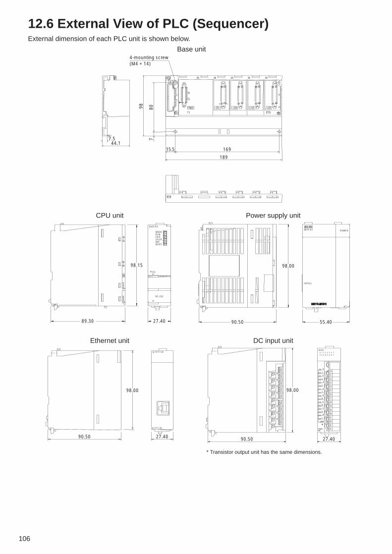
106
12.6 External View of PLC (Sequencer)External dimension of each PLC unit is shown below.
Base unit4-mounting screw (M4 × 14)
7.544.1
16915.5
189
98 807
CPU unit
55.4090.50
98.00
PULL
POWER061P-A1
Power supply unit
98.15
27.40
RS-232
PULL
MODCRUNERR.USERBAT.BOOT
D02CPU
89.30
Ethernet unitQJ71E71-100
QJ71E71-100
98.00
90.50 27.40
DC input unit
* Transistor output unit has the same dimensions.
90.50
98.00
27.40
QX40
0
1
2
3
4
5
6
7
8
9
A
B
C
D
E
F
0 1 2 3 4 5 6 78 9 A B C D E F

107
Power source AC100V
LN
LN
24VGNDE
Circuit breaker for main power source
Arrestor for main power source
Circuit breaker for PLC
Insulating transformer
Power source unit (Q61P-A1)
CPU unit (QO2CPU)
Ethernet unit (QJ71E71-100)
10BASE-T
DC input unit (QX40)
G-50A
PC for TG-2000A
Circuit breaker for DC power source
DC24V Power source
Arrestor
Arrestor
Arrestor
Arrestor
Storage panel for PLC
CPEVS ø0.9-1P or CVVS1.25mm2
Terminal for pulse input
Terminal for pulse input
Terminal for pulse input
Terminal for pulse input
Voltmeter with pulse oscillator
Voltmeter with pulse oscillator
Voltmeter with pulse oscillator
Voltmeter with pulse oscillator
Storage panelfor voltmeter150m
Figure 12-9 Wiring example around PLC
12.7 PLC Wiring DiagramA wiring example around PLC is shown in Figure 12-9. In the figure below are shown also necessarycomponents in order to secure reliability (for reference). Depending on the setting environment, however,unnecessary components may be included. In this case, consult with a contractor to decide whether or notthey are necessary.

108
Table 13-1 Address setting range for M-NET modelsAddress range
000001~050 051~100
101~150
151~200
201~250
Models
G-50AIndoor unit, OA Processing Unit, Lossnay, M-NET interfaceOutdoor unit, BC controller, constant-capacity unit, heat storage tank unitMaster remote control (M-NET remote control)
Slave remote control (M-NET remote control)
System remote control (PAC-SF44SRA)ON/OFF remote control (PAC-YT40ANRA)Group remote control (PAC-SC30GRA) and others
Remarks
Basically, the address range of G-50A is fixed to “000” at the factory.
M-NET remote control includes ME remote control, compact remote control, and Lossnay remote control to connect to M-NET transmission line. When MA remote control is used, address setting is not necessary.G-50A can also be used within the address range shown at the left.
Table 13-2 Address setting range for K-control modelAddress range 001~050 201~250
Models Indoor unit, remote controller (group number)K-transmission converter (PAC-SC25KAA)
Remarks
Minimum address for 200+K-control model indoor unit
Table 13-3 Address setting range for A-control modelAddress range001~050
ModelOutdoor unit (adapter for M-NET connection)
RemarksAddress for refrigerant system is to be set up separately.
13. Step 10: Determination of Address for Air ConditioningInstrument and PC for Control
13.1 Address Setting for Air Conditioning InstrumentAddress setting range for various types of air conditioning instrument is shown in the table below.
Table 13-4 Components required for LANNames of components
Hub for 10BASE-TLAN straight cable (twist pair cable) for 10BASE-T
RemarksRequires either a standard hub for 10BASE-T or a switching hub.The allowable maximum wiring length is 100m in connection. Also, twist pair cable is subject to a standard for category sorting stipulated by EIA/TIA. Twist pair cable in accordance with category 3 and 5 is used for Ethernet, but one in accordance with category 5 is recommended. Over-the-counter LAN cable is in accordance with category 5 and either 10BASE-T or 100BASE-Tx is available.
13.2 Setting of LAN SystemThe components shown in Table 13-4 are required for LAN connection

109
Table 13-5 Recommended IP address setting range
ModelsG-50APC for monitoringPC for TG-2000APLC
PC for initial setting tool
IP address setting range[192.168.1.001] ~ [192.168.1.040][192.168.1.101] ~ [192.168.1.149][192.168.1.150][192.168.1.151] ~ [192.168.1.200][192.168.1.151] ~ [192.168.1.155] for pulse count[192.168.1.171] ~ [192.168.1.190] for general equipment controller[192.168.1.191] ~ [192.168.1.194] for demand input[192.168.1.201]
13.2.1 Setting method for connecting G-50A to exclusive LAN
This is a setting method to establish G-50A system with exclusive LAN wiring
(1) Setting of IP address
In the case that LAN wiring is newly provided for G-50A system, allocate the IP address of G-50A from[192.168.1.1] in sequence. For example, assign [192.168.1.1] for the first G-50A, [192.168.1.2] for thesecond G-50A, and so and so in sequence. In addition, set a PC for monitoring on the Web to monitorG-50A and set the initial setting tool and the like also to the network address in the same system.In case of G-50A exclusive LAN, it is recommended that the IP address of each component is set withinthe following IP address range. As the default value of IP address for G-50A is [192.168.1.1], the address from the second G-50A mustbe changed.
(2) Setting of subnet mask
Set [255.255.255.0] (default value) typically.
* Some models among hubs are provided with exclusive port for connecting between hubs. For G-50A and PC for monitoring, connect to the regular port.
10BASE-T LAN straight cableHUB
1st G-50A 2nd G-50ATG-2000A Initial setting tool
IP address: 192.168.1.1Sub-net mask: 255.255.255.0
IP address: 192.168.1.2Sub-net mask: 255.255.255.0
IP address: 192.168.1.150Sub-net mask: 255.255.255.0
IP address: 192.168.1.201Sub-net mask: 255.255.255.0
Figure 13-1 Setting example for exclusive LAN system

110
Table 13-6 Necessary component in case of incorporating existing LANName of component
RouterMaker for reference: Model name
MELCO: BLR3-TX4Remarks
Install the G-50A, General control PLC (ver.2), and demand input PLC within the same router.
13.2.2 Setting method for connecting G-50A to existing LAN
(1) Case of central monitoring by Web browser
In the case of installing G-50A system in the existing LAN wiring, consult your network administratorwho manages the LAN system to set IP address, subnet mask, and gateway address.Meantime, gateway address can be set only with the initial setting tool.
(2) Case of centralized monitoring by TG-2000A
In the case of using the peak-cut function and charging function by means of TG-2000A, the separationof system by a router is recommended.This is a means to secure the reliability of each component, as various signals are being transmitted ona LAN system in the environment that many PCs for clerical work are installed on the existing LANsystem.Communications with G-50A and PLC are possible by making a router convert the address byassigning an IP address corresponding to the IP address form on the backbone LAN also to G-50A andPLC to access to them by the use of the address.G-50A installed in the downstream of a router is required to register the address of the router as agateway address, but PLC-related devices are not required to.
Backbone LAN
Gateway
IP: 10.130.1.250
Gateway
IP: 10.130.2.250
Obtained from LAN administrator
Obtained from LAN administrator
PC for Web monitoringG-50A PC for Web monitoring
IP address: 10.130.1.1Sub-net mask: 255.255.255.0 Gateway: 10.130.1.250
IP address: 10.130.1.101Sub-net mask: 255.255.255.0 Gateway: 10.130.1.250
IP address: 10.130.2.51Sub-net mask: 255.255.255.0 Gateway: 10.130.2.250
Figure 13-2 Setting example 1 of existing LAN system
Gateway
IP: 10.130.1.254 Obtained from LAN administrator
Obtained from LAN administrator
Backbone LAN
IP address: 10.130.2.202 IP address: 10.130.2.203
Router
G-50A PLC
Gateway address for default: 192.168.1.254
PC TG-2000A PC for clerical work
IP address: 192.168.1.1Sub-net mask: 255.255.255.0Gateway: 10.130.1.250
IP address: 192.168.1.151Sub-net mask: No settingGateway: No setting
IP address: 10.130.2.201Sub-net mask: 255.255.255.0Gateway: 10.130.2.254
Figure 13-3 Setting example 2 of existing LAN system

111
Table 13-10 Necessary components for optical cable systemNames of components
Hub for 10BASE-T/100BASE-TX
Optical media converter (Type A)Optical media converter (Type B)LAN cable (twist pair, category 5)
Optical cable for LAN
RemarksA hub that enables the mutual connection of an optical media converter (100BASE-Tx) and G-50A (10 BASE-T)Be sure to use type A and type B in pairs. ↑Be sure to use the LAN cable in accordance with category 5 corresponding to 100BASE-Tx to connect to an optical media converter.Refer to the operation manual that came with the optical media converter.
13.3 System Using Optical Cable for LANAs stated in item 0, the LAN wiring length in G-50A system can be expanded up to 500m by connecting ahub in the form of cascade connection. However, in the system in which the wiring length requires 500m ormore on the system configuration, Optical cable if used can be extended up to 500m or more.
PC for TG-2000A
G-50A
PLC
G-50A
Optical media converter (Type A)
Switching hub
Optical cable for LAN
Maximum length: 15km
Optical media converter (Type B)
Switching hub
10BASE-T
10BASE-T
10BASE-T
100BASE-Tx
10BASE-T or 100BASE-Tx
100BASE-Tx
Figure 13-8 Chart of LAN system using optical cable
(1) Switching hub
A switching hub is a component to memorize the IP address of equipment to be connected to the hub tohold the route at the other end. There is no limit in its stage due to no need of screening and detectionof the equipment at the other end. For details, refer to Clause 6.3.2.
(2) Optical media converter
This is a converter to transform a regular LAN signal to an optical signal.The recommended MELCO optical media converter has Type A and Type B, and be sure to use inpairs.
(3) Optical cable for LAN
This is optical cable for LAN.Recommended specifications of the optical media converter are as shown in above table. A system with a wiring length of 15km1 can be established by using optical cable.
1 The wiring length for LAN depends on an optical media converter to be used. For details, refer to Instruction Manual for Optical MediaConverter.

112
Power supply unit for transmission line
G-50A
LAN
HUB
MA remote controller
MA remote controller
MA remote controller
Group 1 Group 2 Group 3
Can be operated
Can not be operated
User A of group 1 can operate and browse only the air conditioners of group 1.
User APC for monitoring on the Web
User BPC for monitoring on the Web
User B of group 2 can operate and brows only the air-conditioners of group 2.
Figure 14-1 Outline of individual browser function
14. Step 11: Confirmation of Other Functions14.1 Personal Web FunctionThe Ver.2.6 of G-50A or later is provided with the individual browser function. (License registration required)This function is not available with G-50A versions earlier than 2.6 (For administrator’s web browserfunction, web monitor license registration is required). Please refer to section 2.3 for function licence.
14.1.1 Outline
This function is to be capable of operating and monitoring only the air conditioners (in a unit of group) towhich access is permitted like a local remote control, if a user or an administrator of air-conditionersregisters each group of general users whose access is permitted.As the use of this function enables to set groups of every tenant, which are allowed to operate and monitorair-conditioners, the operation of the air-conditioners by other tenant users can be avoided. In addition, a license registration is required to use this function. If not registered, the air-conditionerscannot be operated by public users.

113
Air conditioners which can be operated Air conditioners which can be operated are displayed. Move the cursor to the icon, then the names of groups are displayed on the screen.
Setting/deleting buttonsThese buttons are to set and delete user information.
User informationThe user names of administrators and air-conditioners available are displayed on the screen. (All the groups of air conditioners under
the control of G-50A are displayed on the screen.)
General user informationThe user names of general
users and groups of air-conditioners available are displayed on the screen.
User nameThe user names of general
users are displayed on the screen. Up to 50 user names can be registered.
Figure 14-2 Window for user registration
14.1.2 User registration from administrator
Administrators (users who access to Web window from administrator.html) perform user registration on theWeb window. Each user name is changeable. Set a pass word to be set together with a user name witheach user.
User name: English half-size characters (Up to 20 characters)Pass word: English half-size characters (Up to 10 characters)
14.1.3 Log-in from public users
The registration of public users from administrators allows operating air-conditioners by general users(users who access to Web window from administrator.html).

114
14.2 Trend Data Output FunctionTG-2000A 4.1 or later version is additionally provided with the trend data output function.
Figure 14-3 Trend data selecting screen
14.2.1 Outline
Trend data and peak cut data in each optional function (measuring instrument charging function and peak-cut function) can be output from CVS file. A trend graph can be developed from the output data in CSV fileby using the Support Tool for Trend Graph in the CD-ROM for Installation of TG-2000A.The trend data which can be output are as shown in Table 14-1.
Trend data output Peak cut data output
Table 14-1 Outline of trend data
�����������
�� � ��� ��� �� �������� ������ �� �������� �������
����� ��������������� ����� ������� ��� ����� ��� �
������� ��� ��� ��� ����� ���� �� ������� �� ��� ���
� ���� ����� � �� �������� ��� � ��� � ��� �� ��� ��
��� � ��� !� �� �������" !� ����
#�� $��� ����� ��� $��� �� ��� ��� � ��� ����� ���� ���
� ����� �������
#������� ����� ���� ���� � ��� ����� ��� �� �$��� ������
����% �� ������ � ��&��&�� �����
#������� ����� ���� ���� � ��� ����� ��� �� �$��� �����
��� �� ������ � ��&��&�� �����
#������� ����� ���� ���� � ��� ����� ��� �� �$��� �����
���� �� ��� �� �� ���� �� ������ � ��&��&�� �����
'����� ����� ���� ���� � ����$� �� �� ���� �
��������� �� ��� �������� ����� �� ��� �� � ����� ��
������ � ��&��&�� �����
(�������� �� ��� ���� �� �������� ����� �� ��� �� �� ��
�� ������ � ���&��& ��� �����
)� ���� ����
*������
'��� ���
#������� �����
�����%�
#������� �����
�'+�
,��&����
����
)�% ��� ��
����� �������
)�% ��� ��
� ����� �������
������ ������ �� ������ ��
��� ������ �������
+����� �� ��
���� ��� ����$��
)�� ���� �� ��
�#$��� �����
)�� ������ �� ��
)�� ������ �� ��
)�� ���� �� ��
)�� ���� �� ��
)�� !���� �� ��
-� �%�
+���� ��
��� ��� ������
.�� ���� ��
�� ��� /����
����� ���� �� ��
����������
+���� ��
��� ��� ������
+���� ��
��� ��� ������
+���� ��
��� ��� ������
Notice
● Trend data output function is on the TG-2000A version 4.1 and later.The output of the operation information on version 4.1 includes the set temperatureand suction temperature only and only generated at 2-minute intervals only.In order to obtain information on stop/start status or operation mode or to change theintervals of sampling, TG-2000A version4.40 or later is necessary.
● Trend data will be stored in the trend data folder for 2 years.After 2 years have passed, the folder for the month past 2 years will be automatically deleted each month. Periodically perform the back up of data in anexternal recording media.
● As for the Trend Data, each file is created by TG-2000A collecting the data from G-50A and PLC.Therefore, in the environment where TG-2000A is not connected full-time or incase that TG-2000A can not communicate with G-50A or PLC, phenomena suchas missing of data and no formulation of a file may be induced.
● Each value shows the value of the unit in the group with the smallest address.
CAUTION

115
Peak cut Executing “Peak cut” allows outputting trend data for peak cut unconditionally.
TrendSetting to “Trend” allows automatically outputting trend data for electric energy. Besides, checking on “Temperature” allows automatically outputting trend data for temperature.
Electric power and measuring instrument
connectedSetting to “Electric power
and measuring instrument connected” allows
outputting trend data for electric energy by block,
electric energy by IC, and watt-hour meter and
measuring instrument.
Electric power PLC included
This setting allows outputting trend data
for electric energy and peak cut.
File output destinationSelects the file output
destination of automatic trend data file.
Setting of output fileSet a folder and file to be output.
Selection of output objectSelect output object to
output trend data.(Selection 1, Selection 2,
Group, etc.)
Selection of periodSelect a date of outputting.
Figure 14-4 Screen for manual output of trend
14.2.2 Preparation for outputting parameter files
In order to output parameter files, a setting on the window of TG-2000A initial setting screen is required.The following conditions allow each trend data to be output.
1 Trend data related to electric power (There are 3 kinds): “Electric power PLC included”, “Watt-hour meter and measuring instrument connected”, and“Trend”.
2 Trend data for temperature: Check on “Trend” and “Temperature”.3 Data for peak cut: “Electric power PLC included” and “Peak cut”.
In case of setting to “Trend”, the selection of an item from “Tool” in TG-2000A menu bar allows outputting atrend data for a desired period. In addition, each trend data is automatically output in a folder for automatictrend output every day or every month to be saved for 2 years.
14.2.3 How to output CVS files
In case of outputting trend data, using each function, the selection of “Tool” in TG-2000A menu bar allowsdeveloping trend data CSV files. Also, at the same time, the trend data CSV file is automatically saved inthe automatic trend output folder every day. The automatic trend output folder is
C:/TG2000A/TrendData/ (Default). Additionally, the folder can be also changed.A yearly folder and a monthly folder are created from each data in an automatic trend output folder to besaved in the folders.
/2003/06/ (Temperature data)Temp[Year-Month-Day]B[Block No.].csv(Year) (Month) (Watt-hour meter, measuring instrument) Mtr[Year-Month-Day].csv
(Monthly report on peak cut) MtrPC[Year-Month].csv(Daily report on peak cut) G50PC[Year-Month-Day].csv

116
14.2.4 Example of CSV files output
Example of each output file is shown as below.In addition, although each relevant datum is shown in each data column, the data value with the followingmark indicates abnormal data.
[-99] : Indicates that TG-2000A have failed to collect normal data from G-50A and PLC.[ ] (Blank): Indicates that the power source for TG-2000A has been off.
(1) Trend data for temperature
Daily basis in a designated period
The apportioned electric power consumption and its charge of every designated charging block are displayed on the screen.
The data apportioned in every block with an outdoor unit equipped with WHM (watt-hour meter) are shown in a column of outdoor unit and the data apportioned in every block with an indoor unit equipped with WHM (watt-hour meter) are displayed in a column of indoor unit.
Selection is possible in group, operating block, and floor.
In a unit of 2 minutes in a designated period
(2) Trend data for watt-hour meter by block
Daily basis in a designated period
Electric power consumption and its charge of every designated indoor unit, floor, and charge block are displayed on the screen.
The data apportioned in every block with an outdoor unit equipped with WHM (watt-hour meter) are displayed in a column of outdoor unit and the data apportioned in every block with an indoor unit equipped with WHM (watt-hour meter) are displayed in a column of indoor unit.
(3) Trend data for electric energy (IC)

117
Hourly basis in a designated period
Consumed integrated electric power of every designated measuring instrument is displayed on the screen.
(4) Trend data for watt-hour meter and measuring instrument
In a unit of 2 minutes on a designated day
Electric power consumption of every G-50A in a unit of 30 is displayed on the screen.
A control level of electric energy of every G-50A in a unit of 2 minutes is displayed on the screen.
(5) Data for peak cut (Daily report)
A designated month (1 to the end of the month)
Daily electric power consumption of every measuring instrument is displayed on the screen.
(6) Data for peak cut (Monthly report)

118
Trend graph buttonTrend data and peak cut data are developed to trend graphs.
Selection of trend dataTrend data and peak cut data files are selected.
Display of a selected fileSelected trend data and
peak cut data files are displayed on the screen. D:¥TrendData¥2003¥07¥Temp2003-07-07B0003.csv
Figure 14-5 Support tool for trend graph
Example of trend graph for inlet temperature Example of trend graph for watt-hour meterintegrated value
Example of trend graph for daily report Example of trend graph for monthly report
14.2.5 Graphing trend data
A trend graph can be developed from a CSV file output as trend data by means of “Support tool fordeveloping trend graphs” in the CD-ROM for TG-2000A installation. [Essentials for display of a trend graph]Excel 2000/XPAn output file of trend data or peak cut data“Support tool for drawing trend graphs (Excel)”
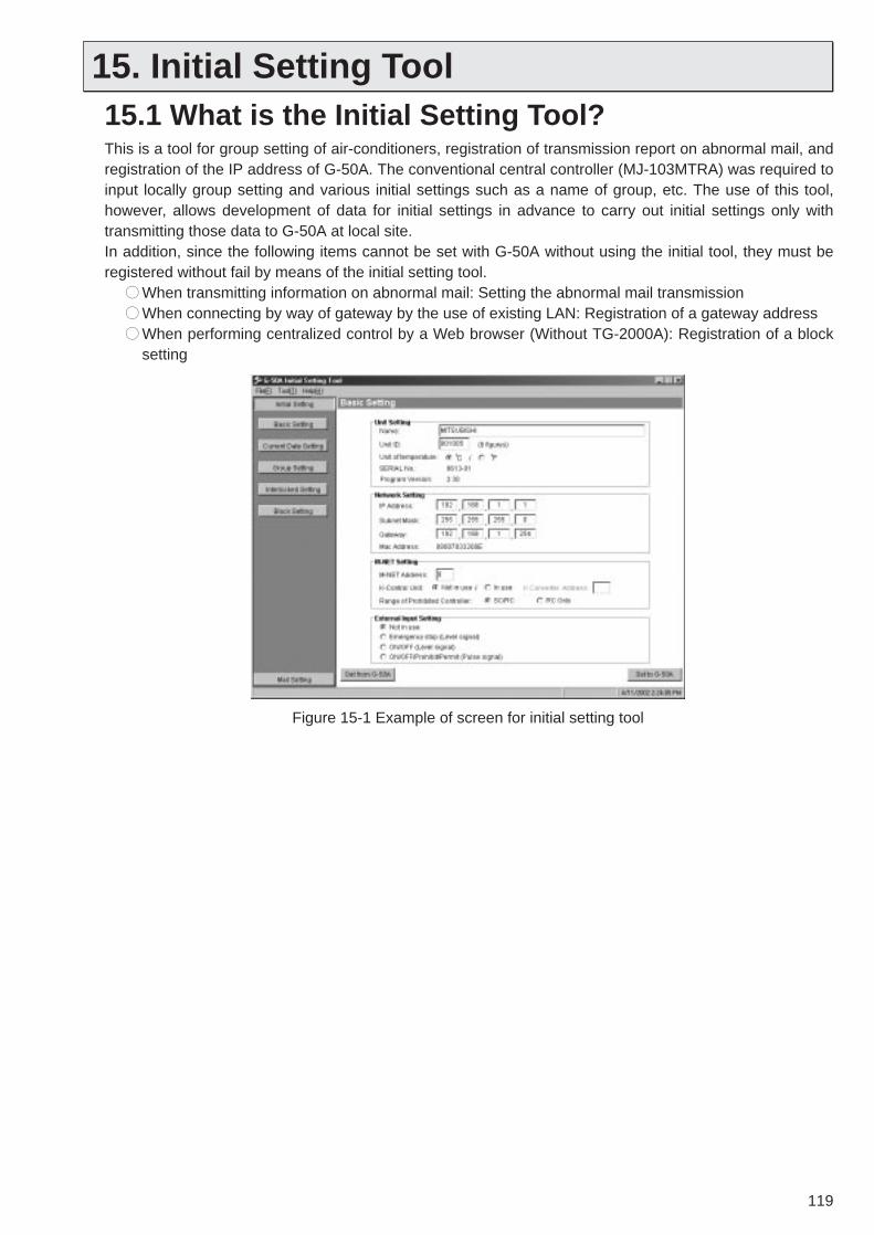
119
Figure 15-1 Example of screen for initial setting tool
15. Initial Setting Tool15.1 What is the Initial Setting Tool?This is a tool for group setting of air-conditioners, registration of transmission report on abnormal mail, andregistration of the IP address of G-50A. The conventional central controller (MJ-103MTRA) was required toinput locally group setting and various initial settings such as a name of group, etc. The use of this tool,however, allows development of data for initial settings in advance to carry out initial settings only withtransmitting those data to G-50A at local site.In addition, since the following items cannot be set with G-50A without using the initial tool, they must beregistered without fail by means of the initial setting tool.
●● When transmitting information on abnormal mail: Setting the abnormal mail transmission●● When connecting by way of gateway by the use of existing LAN: Registration of a gateway address●● When performing centralized control by a Web browser (Without TG-2000A): Registration of a block
setting

120
15.2 Composition of Initial Setting ToolOther than the CD-ROM for initial setting tool, PC and LAN cable are required for the use of the initialsetting tool.
15.2.1 PC for initial settings
A PC for initial settings must be in accordance with the following specifications:
Table 15-1 Operating environmentItems
PCOSCPUHDDMemoryInterface
Others
DescriptionsPC/AT compatibleWindows® 98/Me/2000/XPPentium 133MHz or more20MB or more64MB or moreLAN port(Exclusive 10BASE-T recommended)
CD-ROM drive(Necessary when installing)Pointing devices such as a mouse
Remarks
In case of connecting to G-50A with LAN cable (PAC-YG00FA-E) for initial setting, if the LAN port of a PC is of 10/100BASE-T automatic changeover type, it may not be connected normally. In this case, connect with LAN straight cable with a transmission speed of LAN port of the PC fixed at 10Mbps or with a hub added between G-50A and the PC.

121
Notice
● Refer to Instruction Manual for Initial Setting for a method for connection to the initialsetting tool.
● In the case of connecting to G-50A with LAN connecting cable (PAC-YG00FA-E) forinitial setting which is sold separately, if the LAN port of a PC is of 10/100BASE-Tautomatic changeover type, normal connection may be impossible. In this case, connectwith straight cable by way of a hub additionally provided between G-50A and a PC.
● As a serial number is recorded on the cover, be sure not to confuse the cover for G-50Awith other cover for G-50A when the cover is attached after the completion of initial setting.
Notice
● In the case of connecting to G-50A with crosscable, if the LAN port of a PC is of 10/100BASE-T automatic changeover type, normal connectionmay be impossible. In this case, connect toG-50A with straight cable by way of a hubadditionally provided between G-50A and PC.
15.2.2 Connection to G-50A
There are the following 3 patterns for connecting system to G-50A.
(1) Connection using LAN connecting cable for initial setting (PAC-YG00FA-E)
In the environment where G-50A is installed on the wall, controlpanel, etc., a connection to the LAN connector located backsidemay be difficult.Therefore, a connector for the initial setting tool is mounted onthe control panel of G-50A.If the top cover is removed, LAN communication is switched tothe side of the connector for LAN connecting by switching theLAN change-over switch to the side B.
(2) Connection to the backside of the main body
In the case of connecting directly to the LAN connector locatedbackside of the main body, connect with cross cable.
LAN change-over switch
Connector for LAN connecting
PAC-YG00FA-E
G-50A(in the state of the top cover removed)
Initial setting tool
(3) Connection by way of a hub
In the case that LAN wiring of G-50A is completed andconnecting to the hub is available, connect with straight cablefor 10BASE-T by way of the hub.
(Backside of main body)
Hub
G-50A
Ethernetterminal
Cross cable
Initial setting tool
Straight cable
Initial setting tool

122
- Automatic cooling/heating - changeover mode- Typical group mode
The operation mode is changed over for each changeover block collectively.
(In a unit of mode changeover block)
Status judgment(for every 15 minutes)
TG-2000A G-50A
Group 1 Group 2 Group 3
Group 4
Group 5 Group 6
Changeover block 1
Indoor unitOutdoor unit
Changeover block 2
Figure 16-1 Configuration of auto-changeover system
16. Other function16.1 Auto-Changeover Function (Automatic
Changeover of Cooling/Heating Operation)For the outdoor unit (Y Series) without the function of cooling/heating simultaneous operation, G-50A canjudge whether cooling or heating should be selected by observing a difference between the set and inlettemperature of each indoor unit, and collectively changes over the operation of cooling/heating of indoorunits connected to the outdoor unit. With this function employed, cooling operation is automatically selected if your room is getting hot, whileheating operation is automatically switched over if your room is getting cold.
The auto-changeover function includes two switching modes, [Auto change mode] and [Representationgroup mode]. Either mode can be set from TG-2000A in each changeover block*.* Changeover block : This represents a block in the unit of refrigerant system. When an operation group
over refrigerant systems is set, the plural refrigerant systems for which the groupbelongs to will form a same changeover block.
Table 16-1 Operation detail of each changeover modeChangeover mode
Auto change mode
Representation group mode
Operation detailThe difference between the inlet temperature and set temperature of each air conditioning group is checked once for 15 minutes, and the operation mode (cooling/heating) with higher priority is changed over to operate by considering the air conditioning capacity ratio.When a typical group is assigned, the difference between the inlet and set temperature of the assigned group is checked once for 15 minutes, and the mode is changed over for operation. In the case of the typical group under stopping or fan operation, automatic control takes place with [auto change mode] automatically.

123
Notice ● This function is only applicable to the indoor units connected to M-NET outdoor unit, but notcovering the indoor units connected to K-control outdoor unit and A-control outdoor unit.
● The indoor units under stopping or fan operation are out of the object for changeover.When setting the [Representation group mode], the control will be performedautomatically with the [Auto change mode] if the typical group is stopped or under fanoperation.
● Since the operation mode is determined by judging the status of each indoor unitcomprehensively under the [Auto change mode], comfort may not be maintained at thesurrounding of the air conditioner partially. In such case, use a proper air conditioner asthe typical group under the [Representation group mode].
16.1.1 Auto change mode
Under this mode, the difference of the set and inlet temperature of air conditioning groups (except for thegroup under fan operation or stopping) in a same changeover block is measured to assign points to eachgroup accordingly, and from this resultant total, the changeover mode (cooling/heating) is selected. In order to determine the changeover mode with the consideration of a ratio of the number utilizing each airconditioner, the points by temperature difference are weighted with the capacity value of the indoor unit.
16.1.2 Representation group mode
Judging for cooling/heating to be operated by viewing the set and inlet temperature of assigned airconditioner groups within a changeover block for every 15 minutes, the indoor units within the changeoverblock are switched over to cooling/heating for operation collectively.
When the points of each air conditioner group are multiplied with the weighting factor as below andsummed up, cooling is selected if the result stays on a positive number (over 1) while heating is selected ifit stays on a negative number (below -1).
Weighting= Group capacity/Whole capacity
Group 1 = 9.0/46.4 .=. 19 (%)Group 2 = 4.5/46.4 .=. 10 (%)Group 3 =11.6/46.4 .=. 25 (%)Group 4 = 21.3/46.4 .=. 46 (%)
Group 1
4.5kW
7.1kW 7.1kW 7.1kW 7.1kW
4.5kW 4.5kW 4.5kW
Group 2 Group 3
Group 4
Outdoor unit
Figure 16-2 Weighting of air conditioner group
Table 16-2 Temperature difference between set and inlet temperature and pointsTemperature difference between set
and inlet temperatureSet temperature Inlet temperatureSet temperature Inlet temperature
0 | t| 1.500
1.5 | t| 3.01 x weighting-1 x weighting
3.0 | t|2 x weighting-2 x weighting
Temperature difference and points
Table 16-3 Temperature difference between set and inlet temperature and pointsTemperature difference between set
and inlet temperatureSet temperature Inlet temperatureSet temperature Inlet temperature
0 | t| 1.5Keeping present stateKeeping present state
1.5 | t|Cooling operationHeating operation
Temperature difference and points

Issued in July 2004 MEE04K251Printed in Japan
New publication, effective July 2004.Specifications subject to change without notice.
Mitsubishi ElectricAir Conditioning Network System Centralized Controller G-50A and Integrated Centralized Control Software TG-2000A Technical Manual
HEAD OFFICE: MITSUBISHI DENKI BLDG., 2-2-3, MARUNOUCHI, CHIYODA-KU, TOKYO 100-8310, JAPAN


