Mitsubishi 22kg Feeder_electrical
26
BRN65102-9-* FA-V related/Functional Schematic/Contents.doc/BQNE20541-* FA-S-Advance series Functional Schematic 1. AC200V Wiring (FA20SA) .............................................................................................................. 1 2. AC100V Wiring (FA20SA) .............................................................................................................. 2 3. Remote connection 3.1. Remote connection (FA-SA) ............................................................................................ 3 3.2. Remote connection (FA-SA-V) ......................................................................................... 4 3.3. Remote GND wiring ......................................................................................................... 5 4. Operation panel 4.1. Emergency Stop Circuit ................................................................................................... 6 4.2. NC generator circuit ......................................................................................................... 7 4.3. NC POWER ON circuit .................................................................................................... 8 4.4. NC POWER OFF circuit ................................................................................................... 9 5. Limit Switch 5.1. Limit switch (LS) Machine control box (Column side) ...................................................... 10 5.2. Limit switch (LS) Machine control box (Bed side) ............................................................ 11 6. Generator unit 6.1. Generator FAN (Connection) ........................................................................................... 12 6.2. Generator (Location) ........................................................................................................ 13 7. VG detection (IP>=4, IP<=3) .......................................................................................................... 14 8. Contact (in vertical) detection ......................................................................................................... 15 9. Generator alarm detection.............................................................................................................. 16 10. Specific resistance control 10.1. Specific resistance control (Pump main circuit and solenoid valve) ................................. 17 10.2. Specific resistance control (excluding Pump main circuit and solenoid valve) ................. 18 11. AT Wire Feed 11.1. Main tension control ....................................................................................................... 19 11.2. AT wire feed (CW) ............................................................................................................ 20 11.3. AT wire feed (CCW) ......................................................................................................... 21 11.4. AT wire breakage ............................................................................................................. 22 11.5. AT unit control .................................................................................................................. 23 12. 20 kg wire unit 12.1. 20 kg wire (option) ........................................................................................................... 24 12.2. Table insulation ................................................................................................................ 25 COMPANY PROPRIETARY NOT TO BE REPRODUCED OR DISCLOSED WITHOUT SPECIFIC WRITTEN PERMISSION OF MITSUBISHI ELECTRIC CORPORATION
-
Upload
craig-forcht -
Category
Documents
-
view
45 -
download
3
Transcript of Mitsubishi 22kg Feeder_electrical

BRN65102-9-*
FA-V related/Functional Schematic/Contents.doc/BQNE20541-*
FA-S-Advance series Functional Schematic 1. AC200V Wiring (FA20SA) .............................................................................................................. 1 2. AC100V Wiring (FA20SA) .............................................................................................................. 2 3. Remote connection
3.1. Remote connection (FA-SA) ............................................................................................ 3 3.2. Remote connection (FA-SA-V)......................................................................................... 4 3.3. Remote GND wiring .........................................................................................................5
4. Operation panel 4.1. Emergency Stop Circuit ................................................................................................... 6 4.2. NC generator circuit ......................................................................................................... 7 4.3. NC POWER ON circuit .................................................................................................... 8 4.4. NC POWER OFF circuit................................................................................................... 9
5. Limit Switch 5.1. Limit switch (LS) Machine control box (Column side) ...................................................... 10 5.2. Limit switch (LS) Machine control box (Bed side) ............................................................ 11
6. Generator unit 6.1. Generator FAN (Connection) ........................................................................................... 12 6.2. Generator (Location)........................................................................................................ 13
7. VG detection (IP>=4, IP<=3) .......................................................................................................... 14 8. Contact (in vertical) detection......................................................................................................... 15 9. Generator alarm detection.............................................................................................................. 16 10. Specific resistance control
10.1. Specific resistance control (Pump main circuit and solenoid valve) ................................. 17 10.2. Specific resistance control (excluding Pump main circuit and solenoid valve) ................. 18
11. AT Wire Feed 11.1. Main tension control ....................................................................................................... 19 11.2. AT wire feed (CW)............................................................................................................ 20 11.3. AT wire feed (CCW) ......................................................................................................... 21 11.4. AT wire breakage ............................................................................................................. 22 11.5. AT unit control .................................................................................................................. 23
12. 20 kg wire unit 12.1. 20 kg wire (option) ........................................................................................................... 24 12.2. Table insulation ................................................................................................................ 25
COMPANY PROPRIETARY NOT TO BE REPRODUCED OR DISCLOSED WITHOUT SPECIFIC
WRITTEN PERMISSION OF MITSUBISHI ELECTRIC CORPORATION

1. AC200V wiring (FA20SA)
1A-F1
2A-F1
1B-F1
R
T
S
0V
200V
0V
U
V
W
L1
L3
L2
568
571
L1
L2
L3
NFB F unit MCO(READY ON)
AVR(A+B generator)
DC unit
F1F2
F3
10A
10A
10A
Connector F1
Reservoir
control unit
F4
1.6KVATransformer
UPSD27A
Machinecontrol
(column)
MC1
L11
L21
L11
L21
L1
L3
L11
L21
L1
L3
L2
X/Y axesservo AMP
U axis servoAMP
V axis servoAMP
220V
200V
L11
L21
L1
L3
L2Z axis servo
AMP
5A-B34
3A-B34
4A-B34
6A-B33
4A-B33
5A-B33
5B-B33
6B-B33
6A-B30
4A-B30
5A-B30
5B-B30
6B-B30
1-B31
2-B31M
LubricationpumpMachine control (Bed)
Generator
15A
NF ON
READY ON
(READY ON)
20A
20A
20A
1A-F2
1B-F2
2A-F2
30A
30A
30A
F4A 15A
F7
F8
F9
F11
F12
F13
L2
BRN-65102-9-*
FA-S Advance/FunctionSchematic/BQNE2020541-* -1-

2. AC100V wiring (FA20SA)
KMCB
Branch
connector
F unitGenerator
100
OV2
R12 6A-F1F5(10A)
RA1
MCO
1B-M1410B-M14
5B-B34 NF ON
MC1 FAN
6A-M14
3-CN11-CN1
AVR1,2
NMBA
Machine control (column)
Machine control (Bed)
4-CN11-CN1
AVR3,4
7A-B2
7B-B2
1-CN1
3-CN1
AVR3
6B-B3
6A-B38A-B2
205
214
Reservoircontrol
(READYON)
F1(5A)
R11
PowerON
P-BOX
2B-PR
READYON
2A-F4
RA0
RA1R15
2B-F4
1A-F4
1B-F4 1B-PR
1A-PR
2A-PR
RA04B-B34 APON
8B-B2
ACM2A-B30
3B-B33
2A-B33
3B-B30 APON
3B-B34 R17
2B-B33
R17
2B-B30 R17
RA0
5A-F
3
5B-F
3
4B-F
3
ACM2B-B346B-F1S11 3-CN1
1-CN1
AVR2
NF ON AC100VPOWER ON AC100V
READY ON1 AC100V
READY ON2 AC100VACCOM
READY ON
POWER ON
ACCOM
1A-CON1
1B-CON1
3A-CON1
5A-F1
5B-F1
OSC unit
BRN-65102-9-*
FA-S Advance/FunctionSchematic/BQNE20541-* -2-

Generator LED
3-1. Remote connection (FA-SA)
ON(L) OFF(H)CHGMOD 1.4MBPS 2.8MBPS
Machine control (column side)
Option box
CF10
CG12
KMCBPort 0 and 3 RX312
Port 2(*2)(*4)
FX-BP-Q8MPort 7
(*3)(*4)
UPMAPort 0 and 6
RX3127 port
(*2)(*4)
W31A-02-DWCPort 0(*3)
Debugger addressBA400020:11001111
ARICKMCB (Port 3)
KMCB(Port 0)
CR05A CR05B CR05A CR05B
CR11 CR12
TE2(FSW)
Reservoir control
Debugger addressBA400020:11001111
Basic handy control box
RX312(Port 2)
RX312
Debugger addressBA400020:11001111
HN154
CR05A CR05B CR05A CR05B R-TM
CR11 CR12
UPMA(6,0 port)
Debugger addressBA500020:10010101
OFF 2 3 41
OFF 21
CG12
R-TM
Debugger addressBA600020:00000001
W31A-02-DWC
<RX312 LED>Generator LED: Lights (green) withPOWER ON, READY on withreservoir
Communication LED: Communicationnormal (green), Abnormal (red)
RX312LED
CommunicationLED
<Setting of Dip SW>
*1 Setting of ARIC SW2
3:HI-Z4:CHGMOD
*2 Setting of RX312 DS1
1:HI-Z (Unable to set)2:CHGMOD
*3 Unable to set (fixed)
Communication baud rate Normal
CLK
<Setting of rotary SW>
*4 Port is changeable with rotary SW
n port(n: Set to the port as shown right)
<Communication cable>
If communication cable isdisconnected, RIO error will occur
Option
Generatorcasting
P-BOX
RX312Port 1(*2)(*4)
CR05A CR05B
CR11 CR12
NMBA NMBA
Debugger addressBA400020:11001111RX312 (1 port)
Machine control (Bed side)
CN-WT
Reservoircontrol relay
ARIC-02Port 6(*1)(*4)
RI02
CF10 RI01
High function handy control box (Option)
CON2
RS422
Debugger addressBA500020:01000101
BRN-65102-9-*
FA-S Advance/FunctionSchematic/BQNE20541-* -3-

Option box
RX3127 port
(*2)(*4)
CR05A CR05B R-TM
Debugger addressBA500020:10010101
Option
CF10
CG12
WOSAPort 0, 2 and 5
W31A-02-DWCPort 0(*3)
Debugger addressBA400020:11001111
ARICKMCB (Port 3)
KMCB (Port 0)
CR05A CR05B CR05A CR05B
CR11 CR12
TE2(FSW)
Debugger addressBA400020:11001111
RX312 (Port 2)
RX312
Debugger addressBA400020:11001111
HN154
CR05A CR05B
Debugger addressBA500020:00100101
WOSA(Port 5, 2, and 0)
CG12
R-TM
Debugger addressBA600020:00000001
W31A-02-DWC Generatorcasting
P-BOX
CN-WT
RI02
CF10 RI01
CON2
RS422
Generator LED
<RX312 LED>Generator LED: Lights (green) withPOWER ON, READY on withreservoir
Communication LED: Communicationnormal (green), Abnormal (red)
RX312LED
CommunicationLED
<Communication cable>
If communication cable isdisconnected, RIO error will occur
ON(L) OFF(H)CHGMOD 1.4MBPS 2.8MBPS
OFF 2 3 41
OFF 21
<Setting of Dip SW>
*1 Setting of ARIC SW2
3:HI-Z4:CHGMOD
*2 Setting of RX312 DS1
1:HI-Z (Unable to set)2:CHGMOD
*3 Unable to set (fixed)
Communication baud rate Normal
CLK
<Setting of rotary SW>
*4 Port is changeable with rotary SW
n port(n: Set to the port as shown right)
RX312Port 1(*2)(*4)
CR05A CR05B
CR11 CR12
NMBA NMBA
Debugger addressBA400020:11001111RX312 (1 port)
Machine control (column side) Reservoir control Basic handy control boxMachine control (Bed side)
ARIC-02Port 6(*1)(*4)
KMCBPort 0 and 3 RX312
Port 2(*2)(*4)
FX-BP-Q8MPort 7
(*3)(*4)
High function handy control box (Option)
Reservoircontrol relay
3-2. Remote connection (FA-SA-V) BRN-65102-9-*
FA-S Advance/FunctionSchematic/BQNE20541-* -4-

3-3. Remote GND wiring
P-box Machine control (column side)
Reservoir control
Handycontrol box
Generator unitFG
Central earth plate
UPS
ARIC (#6)
VLQA(#2)
AVR
AVR
0V
FG
0V(LG)
KMCB (#0) (#3)RX312 (#)
AVR
0V (LG)(#7)FG
RG
FG
LG
FG
CNWT
CR05A
FG
LGLG
0V(LG)
CR05B
CR05ACR05A CR05BRI01
0V(LG)CF10
FGFG
CON.UPS
CON.UPS
W31A-02-DWC
0V(RG)
DCOUT
DC INP
FG
PC engineboard
HN154
0V(LG)Contactor
frame
SC2442ITSTR
0V(PGND)
0V (LG)
PGND
SGND
Liquidcrystal
FG
FG0V(LG)
CF10LCD
Machine control (bed side)
Earth via metalspacer
Earth via metalspacer
Earth via metalspacer
Earth via metalbucket
Earth via metalspacer
Contactorframe
Earth via metalbucket
Earth via metalspacer
BRN-65102-9-*
FA-S Advance/FunctionSchematic/BQNE20541-* -5-

4-1. Emergency stop circuit
STOPIN COM
Shield
24V
RA-RDY1
RA-SRDY
RG
4B-S
KS-WK70A
3-EMG
1-EMG
PC engine board
P-BOX
RA-SEMG
NC CPU isinterrupted
HN154
2-EMG
RARDY1
BRN-65102-9-*
FA-S Advance/FunctionSchematic/BQNE20541-* -6-
4-2.NC generator circuit
+5V
+24V(EX)
FG
24V
W31A-02-DWC UPSD27A
1-DCIN2-DCIN
1B-DCOUT
2B-DCOUT
5A/B-UPS6/7B-UPS
+12V
5A/B-UPS6/7B-UPS
RG
10A/B-UPS
FG
3-DCIN 3B-DCOUT
Noisefilter
(+)(-)DC/DC
(5V/24V)
DC/DC(12V/24V)
7A/B-CG12
17A/B-CG1224A/B-CG1238A-CG12
1A/B-CG1233A/B-CG1236A/B-CG12
PC engine board
7A/B-CG12
17A/B-CG1224A/B-CG1238A-CG12
1A/B-CG1233A/B-CG1236A/B-CG12
HN154
5V
12V 24V
24V
Generator castingP-BOX
PCI buss
FG
40B-CG1240B-CG12
3A/B-CG128A/B-CG12 8A/B-CG12
3A/B-CG12
FG
10A/B-UPS
RGRG
8A-UPS8A-UPS
+12V(EX)
RG(EX)
OUT IN GND 1B-UPS
2B-UPS
4B-UPS
6A/B-UPS
7B-UPS
1B-UPS
2B-UPS
4B-UPS
6A/B-UPS
7B-UPS
BRN-65102-9-*
FA-S Advance/FunctionSchematic/BQNE20541-* -7-

4-3. NC POWER ON circuit
1A-S
P-ON +5V
RA-PON
+24V(EX)
1B-S
MAC303C
DO11
DO12
DO16
DI14
RG
IN4
IN3 RAPON
RG
RAPON
Y4
Y3
UPSD27A
W31A-02-DWC(ON21)(ON22)
(ON12) (ON11)
3A-SPower failuretimer circuit
PC engine board
3B-S
4B-S 1-ON/OFF
2-ON/OFF
4-CF24
5-CF24
4-ON/OFF
5-ON/OFF
4A-S
BRN-65102-9-*
FA-S Advance/FunctionSchematic/BQNE20541-* -8-

4-4. NC POWER OFF circuitP-OFF
CON.S
6A
5A
1A
1 NC POWER OFFtreatment
5B
2A
RG
W31A-02-DWC
RA6CON.S
4
3
6B
ON/OFF
RG
MAC303 RA6RG
DCOUT
3B
4B
3B
4B
7A
6A
ON/OFF
CON.UPS
CON.UPS
CON.UPS
ACFAIL
UPSD27A
24V
D01F
2
CF01
2
3
CF24
PC engine baord HN154
9B
9A
CON.SCON.UPS
6A
7A
BRN-65102-9-*
FA-S Advance/FunctionSchematic/BQNE20541-* -9-

Overrun -U
Overrun +VOverrun -VM1-2A
M1-3B
M1-3A
M1-4B
M1-1A
M1-2BRA2
X00-20B
X00-7B
X00-6B
X00-11B
X00-10B
X00-9B
X00-8B
X00-14A
X00-16A
X00-7A
X00-15A
X00-5A
X00-19B
X00-18B
X00-17B
X00-16B
5-1. Limit switch (LS)
Setting of0-MAC303 (9M)
0
Machine unit
Overrun +U
Overrun +Y
Stroke end+U
Stroke end-U
Stroke end+V
Stroke end-V
Wire breakageLS1P24X
Manual operation S/W(Contacts close when PT is off)
M1-7B
M1-8B
M1-5B
M1-5A
M1-6B
M1-9B
M1-9A
M1-10B
M1-10A
M2-1B
M2-2A
M2-3B
M2-3A
M2-4B
M2-4A
M2-1A
M2-2B
M2-6B
M2-6A
M2-7B
M2-7A
M2-8B
M2-8A
M4-1
M4-2
M4-3
M3-5B
M3-1B
M3-1A
M3-2A
M3-4B
Lower collection S/WWire breakageContacts close when wire isbroken
P24X
RGX
Photo sensor(PNP type)
RGX
RGXP24XOverrun Z
Safety cover opens
0.1UF
C67
KMCBOverrun
Stroke end-X
Stroke end+Y
Stroke end-Y
Near point X
Stroke end+U
Stroke end-U
Stroke end+V
Stroke end-V
Wire breakage LS1(Contacts close when "NoWire" is detected)
Wire breakage LS3(Contacts close when wire is broken)
Lower collection SW
Wire breakage LS2(Contacts close when wire isbroken)
M32-2M33-5B
M33-5A
M1-4A
M33-2B
M33-2A
M32-1M1-1B
Overrun+X
Overrun-X
Overrun -Y
M34-2
M34-1
Stroke end+Z
Stroke end-Z
Near point detection Z
RA=ShortcircuitFA=Release
Machine control box (column side)
P24X
RGX
M3-5AM17-1B Overrun +Z
Overrun -Z
M17-1A
M17-2AM17-2B
X00-15BStroke end+Z M17-3BM17-3A
X00-14BStroke end-Z
X00-5B M17-5BM17-5A
M17-4BM17-4A
DI-1B and 2B
DI-18B
DI-1B and 2A
0.1UF10UF
1W1.5K ohmP24X
PTP
0VX
Brown
Black
Blue
Bobbin diametercompensationphoto sensor
(PM2)Pulse input for
bobbin diametercompensation
0VX
P24XSettingof ARICRX312 DI
6
Machine control terminal block
M1-6A
M1-7A
M33-3B
M33-3A
M33-4B
M33-4A
M33-1B
M33-1A
M1-8A
Stroke end+X
Stroke end-X
Stroke end+Y
Stroke end-Y
Stroke end+X
Safety cover Open
Near point detection Z
Near point Y
Near point X
Near point Y
BRN-65102-9-*
FA-S Advance/FunctionSchematic/BQNE20541-* -10-

5-2. Limit switch (LS) Machine control box (Bed side)
Lubrication load detection(Circuit protector)
Lubrication low detection
Cutter load detection(Circuit protector)
Cutter unit detection
Detection of wire comingoff the cutter
Air pressure low
Detection of fluid levelbelow the table (FS)
Working tank door - Upper limit
Safety cover Column
Safety cover Bed
B axsi determination
B axis near point
Right
Left
B8-5B
B8-5A
B8-4BB8-4AB8-3B
B8-3A
B8-2B
B8-2AB3-1B
B3-1AB6-10B
B6-10AB6-9B
B6-9A
B6-4BB6-4AB6-3BB6-3A
B6-2B
B6-2AB6-1B
B6-1A
B8-7B
B8-7A
B8-8B
B8-8AB7-3B
B7-3AB7-2B
B7-2A
NMBA
X01-7A
X01-9B
X01-9A
X01-5B
B2-1B
X01-6A
X01-16B
X01-19A
X01-18A
X01-8B
X01-8A
X01-5A
X01-1B
X01-2B
B2-1A
X01-10A
RAKD
RAKD
65
109
Setting ofRX-312
1
CR11
+24V
From AVR3(LCA10S-24-XMBN)
0V
+24V
Working tank door - Lower limit
Working tank door - Upper limit
Working tank door - Lower limit
BRN-65102-9-*
FA-S Advance/FunctionSchematic/BQNE20541-* -11-

568
571 21
CO
NF1
21
fan2
fan1
CO
NF2
21
fan4
fan3
fan5
CO
NF4
fan8
fan7
21
fan12
fan13
CO
NF3
21
fan11
fan10
1
2
FAN
CO
ND
2
AC200V
RA2
On withREADY
TE3
571
570
F6 (5A)(8) (12)
0.75 black
0.75 black
570
571
B-1
8(19
)UX
2-2X
9
B-1
8(19
)UX
2-2X
9
main unit(A)
main unit(B)
SUB unit
Fan code (T-40-1)
570
571Fan code (T-40-1)
External fan
Fan lead wire
Internal air fan (Heat exchanger)570
571
B-1
8(19
)UX
2-2X
9
B-1
8(19
)UX
2-2X
9
B-18(19)UX2-2X9(Receptacle 170038-4)
Note: Connecting Fan and Branch connector
1. Fan lead wire, Fan code (T-40-1) (Receptacle 170048-4)
* 0.75 Black: B-18(19)U-O
6-1. Generator FAN (Connection)
1A-F3
1B-F3
F unit(CP unit)
Oscillator
Branch connector
Adddition of generator FAN location
8A-AR2 DC
8B-CON AR1
8A-CON AR1
DC unit8B-AR2 DC
RA4B
7A-AR2 DC
1A-COMAR1
7A-CON AR1
1A-AR2 DCRA4B
DC24V
Generatorcooling fan
error
Generator cooling fan error
Fan lead wire
BRN-65102-9-*
FA-S Advance/FunctionSchematic/BQNE20541-* -12-

6-2. Generator (Location)
fan1
fan2
fan3
fan4
fan10fan11
fan5
fan7fan8
fan12
fan13
Door opens inthis direction
BRN-65102-9-*
FA-S Advance/FunctionSchematic/BQNE20541-* -13-

7. VG detection (IP>=4, IP<=3)
RA3
RA4
RA2
RA6
W
E -12V
Rectifier
2-FS
1-FS
1-3
2-3
DK-427
RA6 RA6
9 13 4 8IC3
RA4
4 8
8 4
RA5
RA4
4 6
RA4
11 13
RA4
9 13
RA3
4 8IC3 IC3
VR4RA3
9 13-+
VR2
VR3
RA3
IC2
RA2
8 9
RA2
6 4
RA3
6/AB-NC
2/AB-NC
4/AB-NC
+12V10/AB-NC
5/AB-NC
3/AB-NC
1/AB-NC
8/AB-NC
RA5
4B-RA
1A/B-RA
3A-RA
5A-RA
4A-RA
2A-RAON in case of Ip4 or greater
ON if ST(LC) is selected
ON in case of Machining ON
ON in case of AE21
ON in case of DC
RG
B19-DO
A1/A2-DO
B19-DO
B17-DO
B18-DO
B15-DO
1A-PV
1B-PV
1A-SV
1A-IP3
3B-IP3
3B-SV
3B-PV
2B-PV
ARICNSVB
1 6 1
1 6 1
1 6 1
1 6 1
1 6 1
UPC4741C
UPC4741C
4 6
11 13
IP>=4, HG
IP<=, NM
IP<=3, HG
IP>=4, NM
RA2 RA3 RA4
OFF OFF
OFF
OFF OFF
OFF OFFOFF
OFF
ON
ON
ON
Performance according tocombination of relays
When FM ON
FA20: Located at the rear sideof working tank
(IP>=4, NM)
(DC)
(IP>=4, HG)
(IP<=3, NM)
(IP>=3, HG)
BRN-65102-9-*
FA-S Advance/FunctionSchematic/BQNE20541-* -14-

00-MAC303 (9M)
Setting
Contact effective Y00-12A
KMCB
3-MAC303 (7M)
Perpendicularity gaugeUpper/Contact
3
Setting
Perpendicularity gauge Lower
RG
P24Y
X03-11B
X03-10B
Y03-1A
Y03-2A
Y03-1B
Y03-2B
M5-3A
M5-3B
M5-6A
M5-7B
M5-5A
M5-9A
M5-9B
M5-10A
M5-10B
F1-6A
F1-7B
F1-5A
F1-9A
F1-9B
F1-10A
F1-10B
AG
-12V
RA3
F1-3A
F1-3B
F3-2A
F3-1A
F3-1B
F3-2B
F3-3A
F3-3B
F2-4B
F2-1A
F2-1B
LED4
LED6
OI7
OI6
Pulse Trnasformer RA3
RA3LED5
LED7
3
4
1
2
5
6
UpperLower
LED (Upper)
LED (Lower)
Machine unit
(T/C unit)
Power feed die(WG upper attachmentplate)
Wire pushing felt
NFCA Perpendicularity gauge
8. Contact (in vertical) detection
Pulse Transformer
RA3
RA3
WKPC
P24Y
P24X
P24X
Contact effective
BRN-65102-9-*
FA-S Advance/FunctionSchematic/BQNE20541-* -15-

9. Generator alarm detection
DC unit
OSC unit
WOSA pcb
17-SB 18-SB
SUB unit abnormal
If an error occurs, the value willchange to "0"
Generator coolant fan halt
Alarm messageSUB unit abnormal
DC unit abnormal 1
AVR abnormal
Generator temperature increasing
DC unit abnormal 2
MAIN unit abnormal 1
Debugger address
ADDRESS
0xBA500000
0xBA500002
F E D C B A 9 8 7 6 5 4 3 2 1 0
*
1
*
1
*
*
*
*
*
*
*
1
1
*
*
*
*
1
*
1
*
*
*
*
*
1
*
1
*
1
*
1
R1
R2
2B-AR2
7A-AR2
6A-AR2
4B-AR2
5A-AR2
1A-AR2
KDCA pcb
MAIN unit alarm
1A-CONAR
2B-CONAR
5B-CONAR
6B-CONAR
7A-CONAR
6A-CONAR
4B-CONAR
5A-CONAR
11-AR1
16-AR1
12-AR1
13-AR1
2-AR2
2-AR1
7-AR1
6-AR1
MAIN unit abnormal (Control generator)
MAIN unit abnormal (F3 fuse)
AVR abnormal
DC unit abnormal 1
P24V
AVR1LCA-30S-24
POWER ONAC100V
Branchconnector
AVR1LCA-30S-24
1-CN1
2-CN1
1-CN1
2-CN1
2-CO
N01
1-CO
N01
2B-AL0
5B-AL0
6B-AL0
7A-AL0
6A-AL0
4B-AL0
5A-AL0
1A-AL0
(Contacts close in case of alarms)
3B-C
ON
ALM
3A-C
ON
ALM
5B-C
ON
RA
5A-C
ON
RA
2A-C
ON
A1
2B-C
ON
A1
A+B' generator (MME AVR)
2B-C
ON
ALM
2A-C
ON
ALM
1B-C
ON
ALM
1A-C
ON
ALM
2B-C
ON
AL
1B-C
ON
AL
2A-C
ON
AL
1A-C
ON
AL
8A-CN167A-CN16
AEDA pcb
SUB unit
SUB unit error(Contacts close in case of errors)
RA3
(Contacts open in case of alarms)
MAIN unit abnormal 2MAIN unit abnormal 3
MAIN unit abnormal 4
MAIN unit abnormal 1
DC unit abnormal 2
Generator coolant fan halt
BRN-65102-9-*
FA-S Advance/FunctionSchematic/BQNE20541-* -16-

10-1. Specific resistance control (Pump main circuit and solenoid valve)
F/TRunit
FG
Centralearth plate
MCO
Supply pump
Filteringpump
Rapid fill pump
2B-F2
1A-F2
1B-F2
2A-F2
205B-B3
A-B3
MC7
RA1
OCR2 OCR3 OCR7
MC2
MC7
MCORA4
RA13
RA10
RA5
RA7
RA6
RA8
RA11
RA9
RA19
RA20
RA21
RA22
RAO
SOL C (Lower collection)
NMBA
READY ONAC 100V
MCO RA0
(READY ON)
MC2 OCR2P2
GND
MC3 OCR3P3
MC7 OCR7P7
GND
Unit coolerpump
P1
Unit cooler
1A1B2B60633031
RA 3
RA14
SOL H (Lower collection)3-CN12-CN11-CN1
AVR1
3-CN12-CN11-CN1
AVR2
DC24V
DC5V
205205
214214 214
285284200
V5W5GND
RST
Inverter
GND
RHRMRLSTR
STFSD
BC
GND
UVW
205214
RA2
RA 15RA 16RA 17RA 18RA 3
U7,V7,W7
U3,V3,W3
GND
U2,V2,W2
521
214539
527214
528
540214
534214
SOL E (Jet)
SOL J (Rapid fill)
538
518
SOL BU (Fixed throttle Upper)
517214
214
541
SOL AB (Water purifier)SOL AB (ON-OFF SW)
(SOL F)
SOL J2 (Rapid fill support)
SOL BU (Fixed throttle Lower)
(SOL V)
SOL Z (Nozzle cleaning)
R
S
T
GND
Reservoir control
(Equipped in FA20SA)
(Equipped in FA20SA)MC3RA3
(Equipped in FA10SA)
536536A214
537(Equipped in FA10SA)
BRN-65102-9-*
FA-S Advance/FunctionSchematic/BQNE20541-* -17-

552
R2
ARIC
PC-AVR(A+B' generator)
UVW
701702
NEB
3-phase AC200Input
MC2
240VT1
0V
Specific resistancesensor
R1: 150 ohmR2: 390 ohm
Machine relatedremote
In machine control box
RX312
Microprocessor
NC
10-2. Specific resistance control (excluding pump main circuit and solenoid valve)
MCO (READY ON)
MAC402
MAC202 A/D
conversion
Setting 6
Setting3
5535513A-F2
3B-F23A-F33B-F3
F unit
CN4-5
1B-LR1A-LR3B-LR2B-LR
0V
20V
R1
Generator
NC controlsection
AC240
205
214
232
231230214
555560
556557
554
IAPA
Machine control section
Reservoir
CR05B
+12V
OUT
GND
-12V
+IN
-IN
RA4
AC
M
R17
READ
YO
N100V
MC2
VLQA
20B-CR12
19B-CR12
17B-CR12
14B-CR12
RA3
RA4
RA5
RA6
RA7
FSW3(Cleanwater tank)
FSW2(Used watertank)
12A-CR11
2B-CR11
RA0
13B-CR12
12B-CR12
11B-CR12
RA8
RA9
RA10
RA11
RA12
CR05A
16B-CR1120B-CR111B-CR11
17B-CR11
RA1FSW3
P24
FSW2
RA220A-CR11
19A-CR11OCR2
18A-CR11OCR3
19A-CR11OCR7
RA18
13A-CR12
12A-CR12
10A-CR12
7A-CR12
RA19
RA20
RA21
RA22
1A-CR12
8B-CR12 RA13
6B-CR12
18A-CR12
17A-CR12
16A-CR12
RA14
RA15
RA16
RA17
15A-CR12
(Inverter abnormal)
(Filter pump abnormal)
Supply pump
Filtering pump
SOL J2
SOL E
Rapid fill pump
SOL J
SOL C2
Unit cooler pump
SOL H
SOL Z
SOL BL
SOL BU
Inverter STR
SOL V
Inverter RL
Inverter RM
Inverter RH
SOL C
SOL AB
SOL F
(Rapid fill pump abnormal)
(Unit cooler pump abnormal)
(Unit cooler abnormal)
BRN-65102-9-*
FA-S Advance/FunctionSchematic/BQNE20541-* -18-

11-1. Main tension control
20
21
22
23
24
25
26
27
20
21
22
Machinecondition data
Machinecondition type
Data latch
Tension ON
0
MAC303 (9M)Setting
D/A
6E 6E 1A
MT
External powertransistor
(RA16)READY
ON
KMCB
VR15
Offsetadjustment
Y0B19
Y0B18
Y0B17
M13-2A
M13-1A
RA4
Gainadjustment
VR16
6E6EMain
tensionmotor
(RA22)Wire
breakage
14 8 7 1 6
RA4 RA4
Y0B16
Y0B15
Y0B14
Y0B13
Y0B12
Y0B10
Y0B09
Y0A18
Y0B11
Y0A17
BRN-65102-9-*
FA-S Advance/FunctionSchematic/BQNE20541-* -19-

11-2. AT wire feed (CW)
20
21
22
23
24
25
26
27
20
21
22
Machinecondition data
Machinecondition type
Data latch
Wire feed CW
0
MAC303 (9M)Setting
D/A
6D 6D 1A
F/VGAL
PY1665J
MT
Externalpower
transistor(RA16)
READY ON
5L
5L
KMCB
VR10
Y0B19
Y0B18
M13-2A
M13-1A
M8-1B
M8-1AM8-3AM8-3B
M8-2AM8-2B
P5+A-A
+B-BLG
EN
Encoder
Main tensionmotor
14 7 6
11
5
Y0B10
Y0B09
Y0A18
Y0B11
Y0A20
Y0B17
Y0B16
Y0B15
Y0B14
Y0B13
Y0B12
BRN-65102-9-*
FA-S Advance/FunctionSchematic/BQNE20541-* -20-
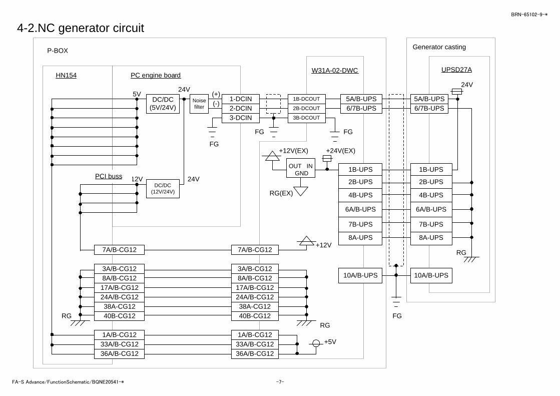
11-3. AT wire feed (CCW)
20
21
22
23
24
25
26
27
20
21
22
Machinecondition data
Machinecondition type
Data latch
Wire feed CCW
0
MAC303 (9M)Setting
D/A
4D 4D 1A
F/VGAL
PY1665J
MT
External powertransistor (RA16)
READYON
5L
5L
KMCB
VR8
Y0B19
Y0B18
M13-2A
M13-1A
M8-1B
M8-1AM8-3AM8-3B
M8-2AM8-2B
P5+A-A
+B-BLG
EN
Encoder
Main tension motor
14 8 6
11
5
Y0B10
Y0B09
Y0A18
Y0B11
Y0A19
Y0B17
Y0B16
Y0B15
Y0B14
Y0B13
Y0B12
BRN-65102-9-*
FA-S Advance/FunctionSchematic/BQNE20541-* -21-
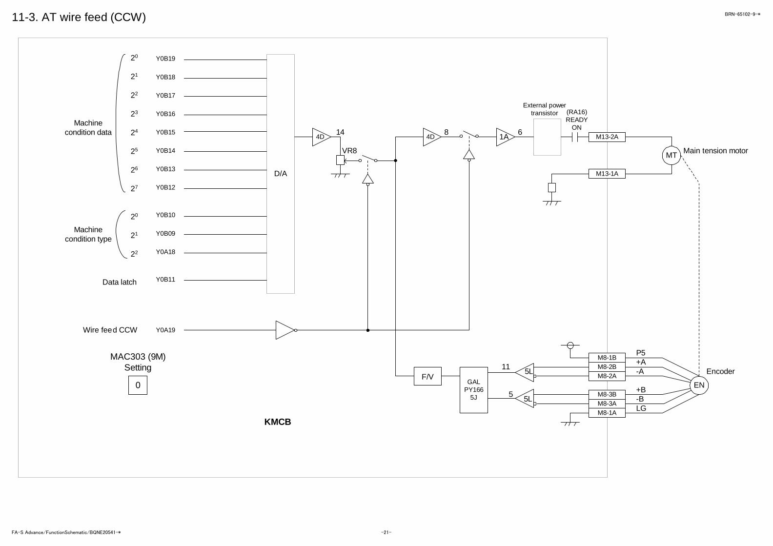
11-4. AT wire breakage
MAC303 (7M)Setting
RA21
KMCB
Y3B18
Y3B20
Y3B07
Y3B06
Y3B05
X3B05
Y3B19
Y3B08
Y3B09
M15-1 CN1-1
M7-2A CN2-2A
M7-10A/B CN2-10A/B
M7-9B CN2-9B
M7-2B CN2-2B
M15-2 CN1-2
M7-4A CN2-4A
M7-4B CN2-4B
M7-5A CN2-5A
M7-3B CN2-3B
M7-3A CN2-3A
M7-1A/B CN2-1A/B
CN3-5A/B
CN3-1 - 4A
CN3-1 - 4B
↑
AVCR: Constant-current generator(MME-AVCR)
AVCR generator(AC100V)
Anneal
Melt-cut
Melt-cutdetection
P24
RG Cuttingcurrent
24
20
21
22
23
Melt-cut RA
Anneal RAAnneal
energizer
Melt-cutenergizer
Commonenergizer
RA21
AC COM
3
RA3
RA1
Output ofcurrent
Wireelectrode
Cutting energizerAVR
Anneal
Cutting
AF cutting detection
M14-10B
M14-6AF1 5A
READY ON
AC100V
RA3
RA1RA2
RA2
RA4
RA4
PC10Turns ON dueto wire melt-cut
AVR2LCA30S-12
AVR3LCA15S-12
P12
OV
OV
N12
2A-M14
4A-M14
3A-M14
20
21
22
23
24Cutting current
Cutting current
Cutting current
Cutting current
Cutting current
BRN-65102-9-*
FA-S Advance/FunctionSchematic/BQNE20541-* -22-

11-5. AT unit control
3
MAC303 (7M)Setting
KMCB
Y3B10
Y3B18
Y3B17
Y3A20
Y3A19
Y3A13
Y3A14
Y3A15
Y3A16
Y3A17
Y3A18
Y3A07
Y3A05
RA37
Y3B16RA39
RA29RA30RA31RA33RA32RA35RA34
RA21RA26RA25RA27RA28
RG
Cutting energizer AVR
Cutting tension 20
Cutting tension CW/CCW
M14-10B
M15-2
M16-1A
M16-2A
M16-3A
M16-4A
M16-5A
M16-6A
M16-7A
M16-9A
M16-10A
M16-7B
M16-8B
M16-9B
M
M
M14-6A
RA21
RA26
RA25
RA27
RA28
RA29
RA30
RA31
RA33
RA32
RA35
RA34
RA37
Wire chipcollection motor
READY ONAC100V
Wire chips collection air
SOL3 Wire guide
SOL6 Energizer retainer
SOL5 Power feeder
SOL7 Wire slip-off prev ention
SOL8 Power feeder
SOL4 Collection roller
SOL2 Air transfer
SOL1 Pipe Lower
Spare
Spare
+12V
F1(5A)
M15-1
M16-1 - 6B
MME-AVCR
7 8
9 8
RA39
4 3
M16-10B4 3
2 3
RG
Air blow
SOL 3
SOL 1
SOL 2
SOL 4
SOL 8
SOL 7
SOL 5
SOL 6
SOL 9
SOL 10
BRN-65102-9-*
FA-S Advance/FunctionSchematic/BQNE20541-* -23-
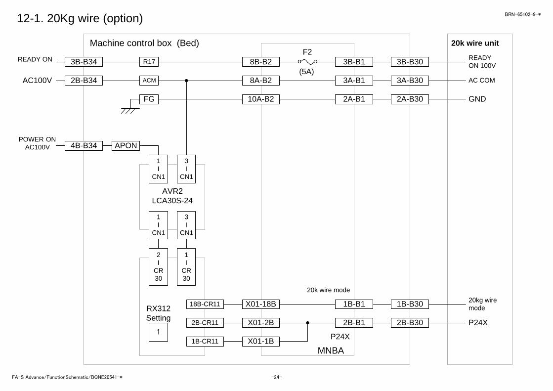
12-1. 20Kg wire (option)
F2
(5A)
Machine control box (Bed)
READY ON
AC100V
FG
1I
CN1
3I
CN1
1I
CN1
3I
CN1
AVR2LCA30S-24
2I
CR30
1I
CR30
18B-CR11
2B-CR11
1B-CR11
RX312Setting
1
3B-B34
2B-B34 ACM
4B-B34 APON
8B-B2
8A-B2
10A-B2
R17
POWER ONAC100V
3A-B1
2A-B1
X01-18B
X01-2B
X01-1B
1B-B1
2B-B1
P24X
MNBA
20k wire mode
3A-B30
2A-B30
1B-B30
2B-B30
3B-B1 3B-B30
20k wire unit
READYON 100V
AC COM
GND
20kg wiremode
P24X
BRN-65102-9-*
FA-S Advance/FunctionSchematic/BQNE20541-* -24-

12-2. Table insulation
1-CN1
3-CN1
AVR2
LCA30S-24
1-CN2
3-CN2
POWER ONAC100V
2-CR30
1-CR30
2A-CR11
1A-CR11
20A-CR11RX312Setting
1
RA111
2 5
Y01-2A
Y01-1A
Y01-20A
8B-B2
8A-B2
1B-B4
8A-B4
R17
ACM
3B-B34
2B-B34
Working tank SOL 4A
Working tank SOL 4B
READY ONAC100V
F2
5A
RA111
1 4
NMBA
Machine control box (Bed)
4B-B34
2B-B34
APON
ACM
BRN-65102-9-*
FA-S Advance/FunctionSchematic/BQNE20541-* -25-