Mitigation PWSCC by Ultrasonic Nanocrystal Surface ... · PDF fileMitigation PWSCC by...
41
Mitigation PWSCC by Ultrasonic Nanocrystal Surface Modification (UNSM) technology International Light Water Reactor Materials Reliability Conference and Exhibition 2016 Hong-Seok Cho 1 , Young-Sik Kim 2 , Auezhan Amanov 3 , Young-Sik Pyun 3 , Hong-Seok Cho 4 , Vijay K. Vasudeva n 5 , Seetha R. Mannava 5 and Abhishek Telang 5 1 Technology Research and Development Institute, KEPCO KPS, Naju 58217, South Korea 2 Materials Research Center for Energy and Green Technology, Andong National University, Andong 36729, South Korea 3 Department of Mechanical Engineering, Sun Moon University, Asan, 31460, South Korea 4 School of Materials Science and Engineering, Pusan National University, Pusan, 46241, South Korea 5 Department of Mechanical and Materials Engineering, University of Cincinnati, Cincinnati, OH 45221-0072, United States Corresponding author: [email protected]
Transcript of Mitigation PWSCC by Ultrasonic Nanocrystal Surface ... · PDF fileMitigation PWSCC by...
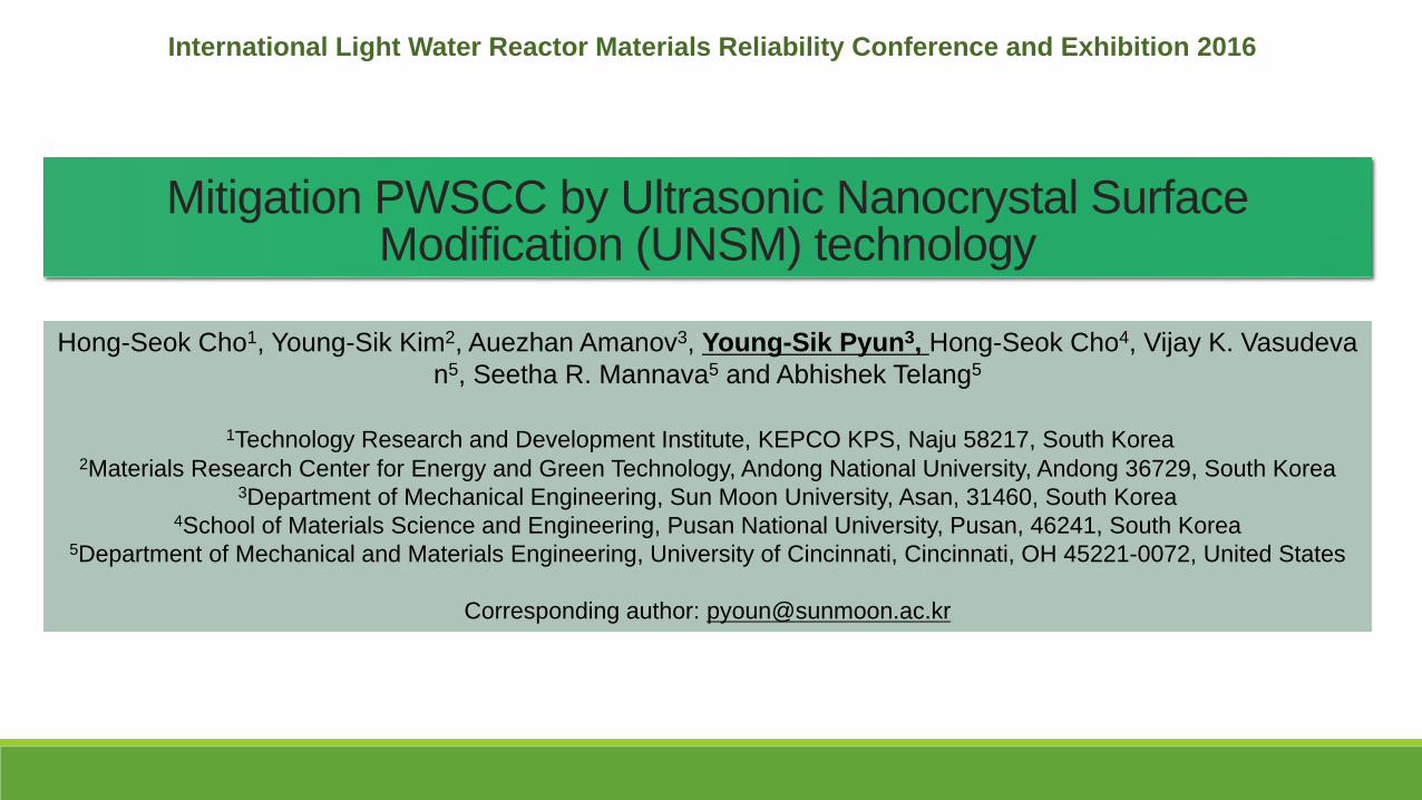
Mitigation PWSCC by Ultrasonic Nanocrystal Surface Modification (UNSM) technology
International Light Water Reactor Materials Reliability Conference and Exhibition 2016
Hong-Seok Cho1, Young-Sik Kim2, Auezhan Amanov3, Young-Sik Pyun3, Hong-Seok Cho4, Vijay K. Vasudeva
n5, Seetha R. Mannava5 and Abhishek Telang5
1Technology Research and Development Institute, KEPCO KPS, Naju 58217, South Korea2Materials Research Center for Energy and Green Technology, Andong National University, Andong 36729, South Korea
3Department of Mechanical Engineering, Sun Moon University, Asan, 31460, South Korea4School of Materials Science and Engineering, Pusan National University, Pusan, 46241, South Korea
5Department of Mechanical and Materials Engineering, University of Cincinnati, Cincinnati, OH 45221-0072, United States
Corresponding author: [email protected]

Contents
I. Motivation and Background
IV. Concluding remarks
II. Microstructural Characterization and Mechanical Properties
of Stainless Steel Inlay Welded Dissimilar Materials by UNSM
III. Changes of Corrosion and SCC Characteristics of
Stainless Steel Inlay Welded Dissimilar Materials by UNSM

I. Motivation and Background
Could the UNSM technology become a Surface Stress
Improvement (SSI) technology which could mitigate
Primary Water Stress Corrosion Cracking (PWSCC)
complying with MRP-335 Revision 3 ?
U.S. NRC(the Nuclear Regulatory Commission) approved the industry’s topical report supporting
appropriate inspection relief with Surface Stress Improvement (SSI) technology (February 2016)


Primary Water Stress Corrosion (PWSCC) Cracking Mitigation by Surface Stress Improvement (SSI) (MRP-335 Revision 3, 3002007392 Final Report, February 2016)
▪ Surface stress improvement (SSI)mitigates PWSCC by inducing compressiveresidual stress at the surface exposed to reactor coolant
– Initiation of PWSCC flaws requires tensile stress at the surface
– Any existing flaws that are fully within the surface compressive stress zone cannot grow via PWSCC
▪ SSI provides an option to mitigate reactor vessel closure head penetration nozzles instead of replacing the entire head
▪ SSI provides an option to mitigate components that are not easily replaced or mitigated from outer surface using weld overlay or mechanical stress improvement (e.g., reactor vessel inlet/outlet nozzles)

SSI (Surface stress improvement) on DWMs (Dissimilar metal but welds)
ASME Code, Case N-766 ( N-516-3, N-770 )
J-Groove Head Vent Nozzles RPVHPNs

Output increased while decreasing operation cost of N-Power plant by “Acceptance of Inspection Relief ”
Asset Management
(10 CFR 50.59 Process)
Licensees may make changes to the facility, procedures and conduct tests and experiments without prior NRC approval
If change requires no license or technical specifications modifications
If change does not meet one or more of the eight criteria specified in 10 CFR 50.59(c)(2)
No license amendment request required
This process does not grant inspection relief
Optimized Inspection Intervals
(10 CFR 50.55a Process)
For NRC (the Nuclear Regulatory Commission) approved and regulation-mandated programs (e.g. in-service inspection programs) separate from the license
Licensees may submit “relief requests” to the NRC
NRC reviews and approves relief requests by Safety Evaluations (SE)
10 CFR 50.55a specifies the processes for requesting alternatives to, or relief from, the in-service inspection and testing requirements of the ASME Code
Code of Federal Regulations
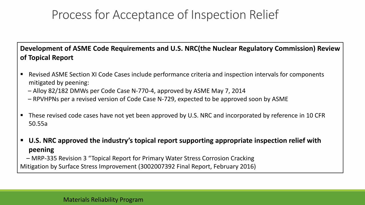
Process for Acceptance of Inspection Relief
Development of ASME Code Requirements and U.S. NRC(the Nuclear Regulatory Commission) Review of Topical Report
Revised ASME Section XI Code Cases include performance criteria and inspection intervals for components mitigated by peening:– Alloy 82/182 DMWs per Code Case N-770-4, approved by ASME May 7, 2014– RPVHPNs per a revised version of Code Case N-729, expected to be approved soon by ASME
These revised code cases have not yet been approved by U.S. NRC and incorporated by reference in 10 CFR 50.55a
U.S. NRC approved the industry’s topical report supporting appropriate inspection relief with peening
– MRP-335 Revision 3 “Topical Report for Primary Water Stress Corrosion CrackingMitigation by Surface Stress Improvement (3002007392 Final Report, February 2016)
Materials Reliability Program

A novel SSI “UNSM” integration with Inlay Welding in Korea
KURIS : KPS Underwater Repair & Inspection System
UNSM: Compressive residual stress and improving Surface roughness
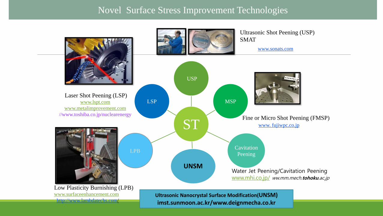
Fine or Micro Shot Peening (FMSP)
Ultrasonic Shot Peening (USP)
SMAT
Low Plasticity Burnishing (LPB)
Laser Shot Peening (LSP)
www.surfaceenhancement.com
http://www.lambdatechs.com/
www.lspt.com
www.metalimprovement.com
//www.toshiba.co.jp/nuclearenergy
www.sonats.com
www. fujiwpc.co.jp
Ultrasonic Nanocrystal Surface Modification(UNSM) imst.sunmoon.ac.kr/www.deignmecha.co.kr
Novel Surface Stress Improvement Technologies
Water Jet Peening/Cavitation Peeningwww.mhi.co.jp/ ww.mm.mech.tohoku.ac.jp
ST
USP
MSP
Cavitation
Peening
UNSM
LPB
LSP

Forge (Human) Forge ( Machine)
The Ultrasonic Nanocrystal Surface Modification (UNSM) technology
Conventional Forging
Less than
- 10 strikes / mm2
- 1,000 strikes / minute
- 3 Giga Pascal
N = 60f / SV - Contact count per unit area (mm2)
F = Fs+Fd =m(g + A/(2πf)2)Maximum total striking force
m – weight of static load onto the tool;
g – standard gravity; A – amplitude;
V - speed(m/min); S – feed (mm/rev); r - ball radius; R - specimen radius;
t – time (sec.); f- frequency
Generator
장치선단부분피가공물
장치선단부분피가공물
Wor
kpi
ece
UNSM Forging Mechanism
- 1,000 ~ 100,000 strikes/mm2
- Up to 2.4 million strikes/min
- 3 ~ 30 GPa contact pressure

UNSM schematics & Device
The UNSM device
Outer surfaceInner surface Horizontal Machining
Center
Vertical Machining
Center
UNSM device can be mounted on any machine,Even on robots and hand held manual operation

Nano scale roughness
Increased hardness
Compressive residual stress
Surface Modification by UNSM
UNSM Anticipated benefits
Deep compressive residual
stresses
(Greater than 1000MPa into
depths of more than 2000 ㎛ )
1) Improved LCF and HCF
endurance limit
2) Improved rolling contact fatigue
strength
3) Improved stress corrosion
cracking resistance
Micro dimples surface
(Dia. of area:1-2㎛2 ),
Depth : sub micron, Pattern pitch:
few ㎛)
1) Reduced surface roughness
2) Decreased friction coefficient
3) Reduced wear rate
Increased hardness
(into depths of more than 1500
㎛ )
1) Reduced wear rate
2) Improved LCF and HCF
endurance limit
Nanocrystalline structure
(Grain Sizes of 50-200 nm into
depths of 100 ㎛ )
1) Increased tensile strength and
hardness,
2) Increased fatigue strength,
3) Increased wear resistance
Top surface : Nano level surface roughness + texturing structureSubsurface : Nano crystal structure + improved hardness + compressive residual stress
~100nm
~1000nm
Microstructurally & Mechanistically Gradient Structure

LSP
UNSM
CSP
~50 nm sub-grains with
high dislocation
density and twins
50-100 nm
crystallites with
high dislocation
density and twins
30-100 nm
grains
UC + Tohoku
case: IN718 SPF MaterialsScience&EngineeringA576(2013)346–355C

DEPTH FROM
SURFACE(㎛)
GRAIN SIZE (㎚)
5 30
10 36
20 42
30 45
A. Cherif, Y. Pyoun and B. Scholtes, Journal of Materials Engineering and Performance,
Volume 19, Number 2, 282-286
Case: AISI 304
AfterBefore
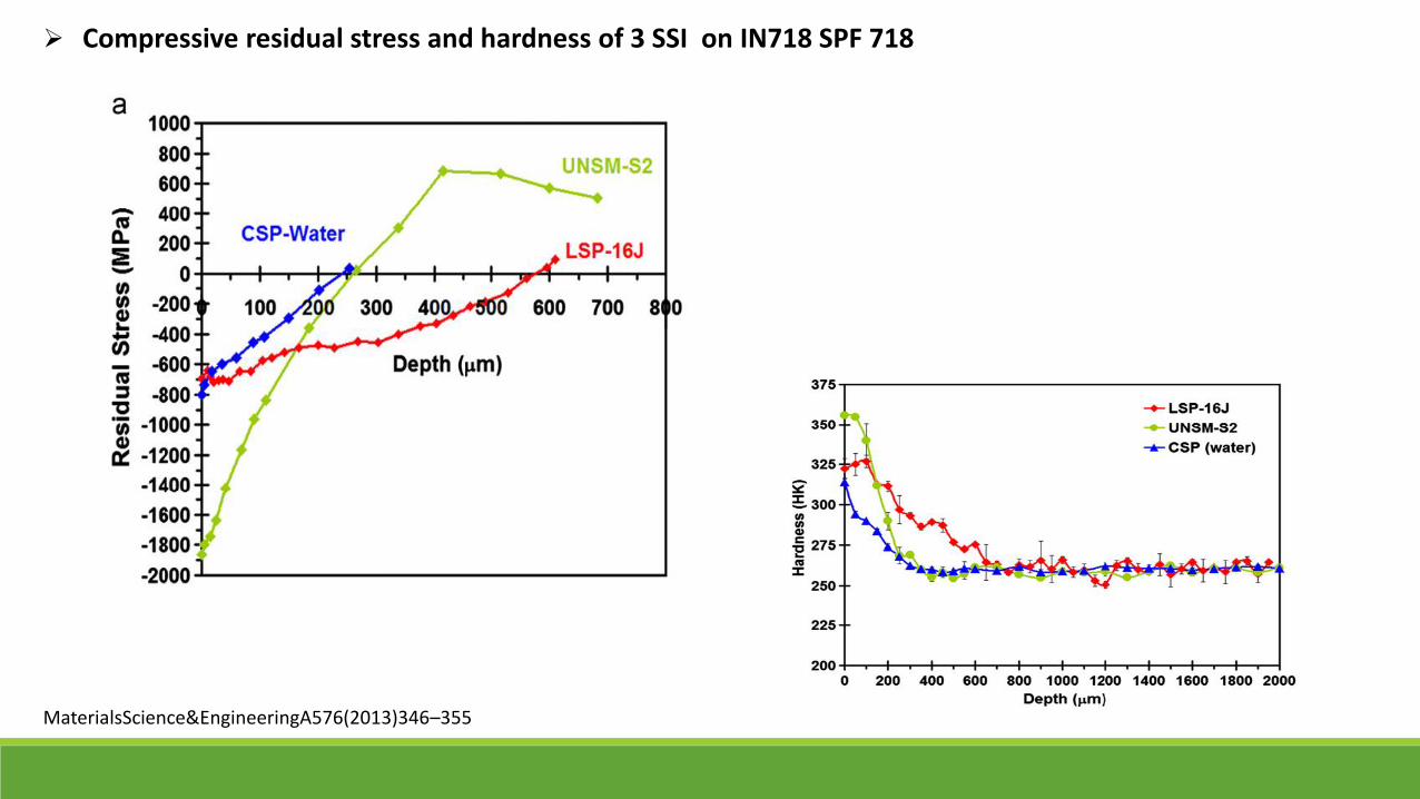
Compressive residual stress and hardness of 3 SSI on IN718 SPF 718
MaterialsScience&EngineeringA576(2013)346–355

II. Microstructural Characterization and Mechanical Properties ofStainless Steel Inlay Welded Dissimilar Materials by UNSM

SSRT specimen
U-bend test specimen
DMW test Specimens
DWM
DWM
Inlay Weld Mockup specimen
Welding & InspectionASME Section IX

UNSM Parameters
Condition 316L/alloy 82
Amplitude 60μm
Static load 30N
Pitch 0.03mm
Speed 1500mm/min
Tip diameter 2.38mm(WC)
UNSM treatment condition
Material composition
Composition, wt%
Ni Co Cr Fe C Ti Al Mo P Cu Mn Si S
316L 10 - 18 68.5 0.08 - - 2 0.045 - 0.07 1 0.03
Alloy 52 60 28 7 0.04 1 1.1 0.5 0.02 0.3 1 0.5 0.015
Alloy 82 74 18 3 0.1 0.75 - - 0.03 0.5 2.5 0.5 0.015

Effective Depth of UNSM (OM)


Microstructure of Weld Zone after UNSM

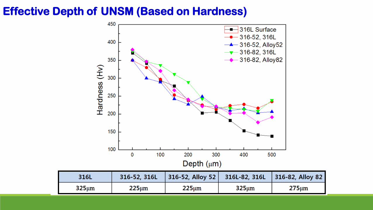
Effective Depth of UNSM (Based on Hardness)

Weld Zone Hardness Mapping


Current (A) Voltage
(V)
Wire speed (IPS) Travel
speed (IPS)
Gas flow rate
(L/min)PRI BKG PRI BKG
Cladding 180∼260 80∼160 9.2∼9.8 30∼70 30∼60 3.0∼3.8 15∼19
Buttering 180∼200 80∼100 9.5∼9.7 35∼42 35∼42 3.5∼4.2 15∼18
DM weld 160∼180 60∼90 9.3∼9.5 20∼40 20∼40 3.0∼3.5 15∼18
Weld process conditions and Heat treatment condition after welding
Inlay Weld Mockup specimen
Condition Specification Actual
Unloading temperature(℃) 425 375
Heating rate Max.56℃/Hr. 40℃/Hr.
Holding temperature(℃) 600∼620 608∼612
Holding time Min.2Hr 30min 2Hr 40min
Cooling rate Max.56℃/Hr. 40℃/Hr.
Unloading termperature(℃) 425 370

Vickers hardness(Hv)
XZ plane XY plane
1 2 3 4 1 2 3
Alloy 82
Before 139 211 173 186 140 230 152
After 159 240 229 238 160 302 250
Alloy 52
Before 138 210 175 173 106 253 138
After 154 243 230 237 161 262 263
Vickers hardness
before and after UNSM treatment
Before UNSM After UNSMRemarks
82 DWM 52 DWM 82 DWM 52 DWM
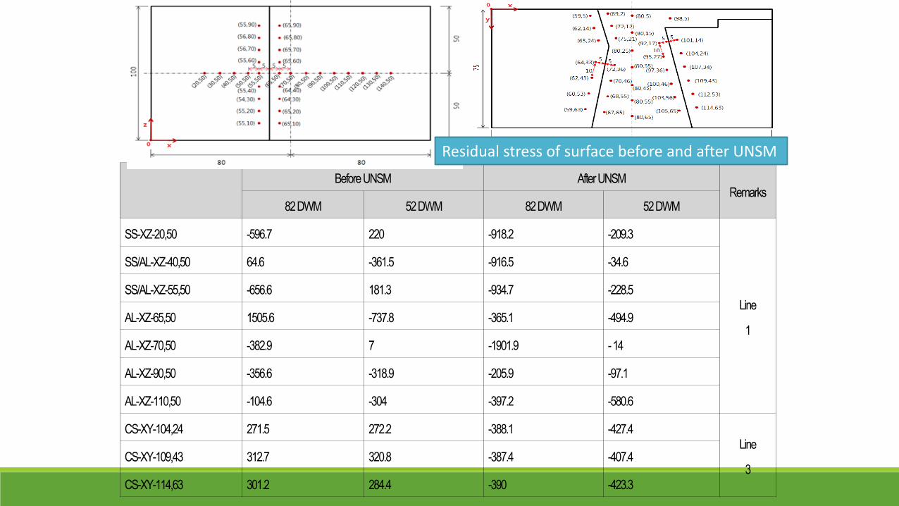
SS-XZ-20,50 -596.7 220 -918.2 -209.3
Line
1
SS/AL-XZ-40,50 64.6 -361.5 -916.5 -34.6
SS/AL-XZ-55,50 -656.6 181.3 -934.7 -228.5
AL-XZ-65,50 1505.6 -737.8 -365.1 -494.9
AL-XZ-70,50 -382.9 7 -1901.9 -14
AL-XZ-90,50 -356.6 -318.9 -205.9 -97.1
AL-XZ-110,50 -104.6 -304 -397.2 -580.6
CS-XY-104,24 271.5 272.2 -388.1 -427.4Line
3CS-XY-109,43 312.7 320.8 -387.4 -407.4
CS-XY-114,63 301.2 284.4 -390 -423.3
Residual stress of surface before and after UNSM

III. Changes of Corrosion and SCC Characteristics of
Stainless Steel Inlay Welded Dissimilar Materials by UNSM
- Improved resistance to Stress Corrosion Cracking(SCC) of Alloy 600

By ASTM A 262 Practice C/boiling 65% Nitric acid (HNO3)
Intergranular Corrosion Rate Results of 316L/Alloy 82
316L/Alloy 82(S2)
316L/Alloy 82U(S2)

Sodium sulfate (Na2S2O3) 0.1M
Anodic Polarization Test Results of 316L/Alloy 82

Stress Corrosion Cracking resistance by UNSM
↑
(Sodium hydroxide (NaOH) 40%

Improved resistance to Stress Corrosion Cracking(SCC) of Alloy 600Materials Science&EngineeringA648(2015)280–288
UNSM ParametersStatic load:20N, Amplitude 8 um, Scan speed 3000mm/min Scan interval 30 um
Residual stresses and (b)FWHMafterUNSMinAlloy600

Slow strain rate tests
Sodium sulfate

Materials
316L/alloy 82, 316L/alloy 52, 316L
SCC tests
SSRT in simulated 1’ry water(320OC, strain rate: 8.7x10⁻⁸/sec)
U-bend in 320OC, 40% NaOH
U-bend in 340OC, 0.01M Na2S4O6
Corrosion tests
Intergranular corrosion test
•A262 pr. A
•DL-EPR test
•A262 pr. C
Anodic polarization test
•0.1M Na2SO4, 0.1M Na2S2O3, 3.5% NaCl
AC Impedance measurement, Mott-Schottky plot
Ongoing test
Sodium hydroxide: NaOH, Sodium Sulfate: Na2SO4, sodium thiosulphate: Na2S2O3, Sodium chloride:NaCL

IV. Concluding remarks
▪ UNSM, a novel surface stress improvement (SSI), could also
mitigate PWSCC by inducing compressive residual stress at the
surface exposed to reactor coolant as like LSP and WJP.
Every technology has pros and cons due to it’s unique
characteristics, but UNSM could improve surface roughness
only among three technologies. UNSM can treat ceramics,
TSC and even Si Wafer for solar cell, etc.
The answer to “ Could the UNSM technology comply with the re
quirement of “MRP-335 Revision 3 “Topical Report for Primary Water Stress Corrosion Cracking Mitigation by Surface Stress Improvement” is Yes,
but ……
Any requests for collaboration are welcome !
Questions and comments !!!
IV. Concluding Remarks

THANK YOU FOR YOUR ATTENTION!!!

Before UNSM After UNSMRemarks
82 DWM 52 DWM 82 DWM 52 DWM
SS-XZ-20,50 -596.7 220 -918.2 -209.3
Line
1
SS/AL-XZ-40,50 64.6 -361.5 -916.5 -34.6
SS/AL-XZ-55,50 -656.6 181.3 -934.7 -228.5
AL-XZ-65,50 1505.6 -737.8 -365.1 -494.9
AL-XZ-70,50 -382.9 7 -1901.9 -14
AL-XZ-90,50 -356.6 -318.9 -205.9 -97.1
AL-XZ-110,50 -104.6 -304 -397.2 -580.6
CS-XY-104,24 271.5 272.2 -388.1 -427.4Line
3CS-XY-109,43 312.7 320.8 -387.4 -407.4
CS-XY-114,63 301.2 284.4 -390 -423.3
Residual stress of surface before and after UNSM

Microstructure Analysis after UNSM
316L 316L/52 316L/82 Alloy600 Alloy690
- Deformation bands near
the UNSM-treated
surface
- Austenite matrix
- Twin boundaries
- Presence of delta ferrite
- Effective depth: 212.5
μm
- Alloy 52: intragranular
networks and
coarse/equiaxed grains
- Uneven bond line
- Effective depth: 102.1
μm
- Alloy82: intragranular
networks and columnar
grains
- Uneven bond line
- Effective depth: 126.9
μm
- Relatively large grain
size
- Severe plastic
deformation near the
UNSM-treated surface
- Effective depth: 237.9
μm
- Deformation bands near
the UNSM-treated
surface
- Effective depth: 52.7 μm
Materials Microstructure analysis Hardness test Residual stress
calculation
- Ferrous Alloy : 316L stainless steel
- Welding : 316L/Alloy52, 16L/Alloy82
- Nickel-based alloy : Alloy 600 & 690
- Optical microscopy & electron microscopy
- Effective depth measurement
- Through-thickness mapping & profiling
- Effective depth measurement
- Using X-ray technique

Hardness and Residual Stress Measurement
316L 316L/52 316L/82 Alloy600 Alloy690
- Effective depth : 400μm - Near-surface hardness is
similar between 316L and
Alloy 52.
- Matrix hardness is lower in
Alloy 52.
- Effective depth: 275μm
- Near-surface hardness is a
little bit higher in Alloy 82.
- Matrix hardness is lower in
Alloy 82.
- Effective depth: 225μm
- Effective depth: 325μm - Effective depth : 150μm
Residual stress measurement using X-ray technique
Residual Stress, MPa
316L -508.8
Alloy600 -1020.6
Effective depths measured from the microstructure analysis and the micro-hardness profiles