Missouri Society of Professional Surveyors
142
Missouri Society of Professional Surveyors Lodge of the Four Seasons Lake Ozark, Missouri May 6-7, 2011
Transcript of Missouri Society of Professional Surveyors

Missouri Society of Professional Surveyors
Lodge of the Four SeasonsLake Ozark, Missouri
May 6-7, 2011
SpeakersRobert Ross, PLS
Chief of the Cadastral Section at the State Land Surveyor's Office in Rolla, Missouri. Attended Missouri State University (formerly SMSU) in Springfield, Missouri, and received a Bachelor of Sciencedegree in Cartographic Sciences, with an emphasis in Land Surveying. As Section Chief he oversees programstaff, performs survey investigations and dependent resurveys, administers boundary project contracts and thePrivate and County Surveyor Cooperative remonumentationprograms.

SpeakersRalph Riggs, PLS, CFedS
President of Riggs & Associates, Inc., West Plains, Missouri and Managing Member of Ruble, Riggs & Shotts LLC. He is currently the Howell County Surveyor and is licensed in Missouri, Kansas, Arkansas, and Louisiana and is a Certified Federal Surveyor. He is a past president of MSPS and is a currently member of MSPS, MACS (Past President), NSPS, Arkansas ASPS. He has also been a member of and past chairman of the Land Survey Advisory Committee and is the recipient of the MSPS Surveyor of the Year in 2010.

SpeakersRobert Shotts, PLS, ASLA, CFedS, CFM
President of Robert S. Shotts, Inc., Lebanon, Missouri and Managing Member of Ruble, Riggs & Shotts LLC. He is currently the Laclede and Wright County Surveyor and is a Certified Floodplain Manager. He is licensed in Missouri, Kansas, Arkansas, Colorado, Illinois and is a Certified Federal Surveyor. He is also licensed as a Landscape Architect in Missouri, Kansas and Arkansas. He holds a BS in Forestry from the University of Missouri-Columbia and has graduate work in Landscape Architecture from Kansas State University. He is a past president of MSPS and is a currently member of MSPS, NSPS, MACS, MALA, ACSM, ASLA and the Association of State Floodplain Managers. He is a recipient of the MSPS Surveyor of the Year award and the Robert E. Myers Service award.
General Concept and EvolutionSubdivision of Sections
The Role of the Plat
Fifth Principal Meridian

General Concept and Evolution Land Ordinance of 1785
36 Lots per Township Each Lot was to be 1 Mile Square Townships to be 6 Miles Square Lot lines would not be surveyed by the government The purchaser would survey his lot line after purchase Five lots reserved
Lots 8, 11 & 26 were reserved to the government Lot 16 to schools Lot 29 to “religion”
Under the direction of Geographer, Thomas Hutchins

Township Scheme

General Concept and Evolution(Continued)
Seven Ranges surveyed from 1785-1787 Problems began immediately
Numbering became a problem The township exteriors were poorly surveyed Individual lots were poorly surveyed Conflicts between lots were common
Gores Overlaps

Boundary of the 7 Ranges
General Concept and Evolution(Continued)
Congress contracted with the Ohio Company to sell one million acres west of the Seven Ranges
Ohio company had to survey the townships and lots The Company surveyor was Rufus Putnam who
contracted with private surveyors to conduct the work Greenville Treaty of August 3, 1795 after General Mad
Anthony Wayne defeated the Indians at Fallen Timbers

General Concept and Evolution(Continued)
The Act of May 18, 1796 The office of the Surveyor General was created by this
Act, Rufus Putnam appointed to this position He contracted with Deputy Surveyors who were paid by
the mile Lots became Sections Current township scheme was created, Section 1 in the
NE corner of the township 2-pole chain is to be used Corner descriptions are to be recorded in a field book

General Concept and Evolution(Continued)
Reference to navigable rivers as public highways Every other unsold township was to be divided
into nine four-mile square blocks

General Concept and Evolution(Continued)
The Act of May 10, 1800 Townships were to be divided into sections and half
sections Corners to be set at one mile intervals Half mile corners were to be fixed on the E-W lines only Allowed the sale of ½ sections (320 acres) Established local land offices

Act of 1800 Monumentation

General Concept and Evolution(Continued)
The Act of March 26, 1804 Provided for the sale of ¼ sections
General Concept and Evolution(Continued)
The Act of February 11, 1805 Original corners control The boundaries as run and marked cannot be changed Measurements and quantities returned are held to be
true (Proportionate measure basis) Aliquot parts of the sections are defined Statutory rules for the subdivision of sections are
defined Rules for the subdivision of fractional townships and
sections

General Concept and Evolution(Continued)
The Act of April 24, 1820 The sale of ½ quarter sections (80 acres) The N-S lines through the quarter sections to be in
accordance with the Act of 1805

General Concept and Evolution(Continued)
The Act of April 5, 1832 The sale of quarter-quarter sections (40 acres) The E-W lines through the quarter section to be in
accordance with the Act of 1805
Subdivision of SectionsRole of the Plat

Subdivision of SectionsRole of the Plat
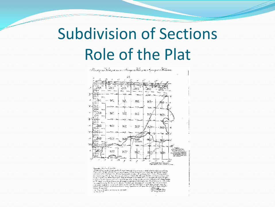
BLM: Survey plats are part of the official record of a
cadastral survey. Surveying is the art and science of measuring the land to locate the limits of an owner's interest thereon. A cadastral survey is a survey which creates, marks, defines, retraces or re-establishes the boundaries and subdivisions of Federal Lands of the United States. The survey plat is the graphic drawing of the boundaries involved with a particular survey project, and contains the official acreage to be used in the legal description.
Subdivision of SectionsRole of the Plat
Functions of the GLO Plat The returns of the lines and areas Sections are not subdivided in the field Certain of the subdivision-of-the-section lines are
protracted on the official plat Subdivision-of-the-section corners are not marked in
the field Tracts having senior rights are shown on the plat
Grant, Lease, Order, Proclamation, reservation, & etc.
Subdivision of SectionsRole of the Plat
Scrivener (Draftsperson) Plat each section in accordance with the field notes Subdivide each section:
In conformity with the uniform plan Connecting by straight lines between opposite corresponding
corners Excess or deficiency against the township boundary ( N & W) As many aliquot parts as possible Follow lotting principals

Subdivision of SectionsRole of the Plat

Subdivision of SectionsRole of the Plat
General Rules of Subdivision, Regular Sections Quarter-quarter sections are aliquot parts of the quarter
sections-lines not indicated on plat Sections subdivided to include as many aliquot parts as
possible Sections invaded by meanderable water bodies and
approved claims divided into as many aliquot parts as possible then lots as necessary

Subdivision of SectionsRole of the Plat
General Rules of Subdivision, Fractional Sections First, subdivision by protraction in accordance with field
notes Second, subdivision by protraction as near as possible
with uniform plan for fractional sections Subdivision-of-section lines are terminated at the
meander line or claim line

Subdivision of SectionsRole of the Plat

Subdivision of SectionsRole of the Plat
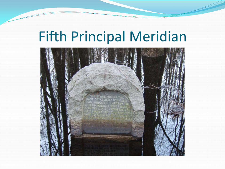
Fifth Principal Meridian
Fifth Principal Meridian

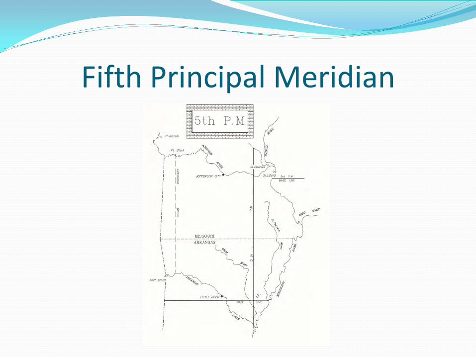
Fifth Principal MeridianThe Baseline
Joseph C. Brown began the survey of the base line on October 27th 1815the same day P. K. Robbins began his survey of the 5th Principal Meridian.
Brown arrived at the initial point on November 2, but was unawareof this until later.Chs. West on the base line, commencing at a
post on the south bank of the St. Francisriver at its mouth, from which a Hickory2 feet diam. Bears S31E 61 links and a Hickory 1 ½ feet diam bears N87W 2 chs.6 links – The Mississippi here is 50 chs.-- links wide and bears S. 12 E.

Fifth Principal MeridianThe Baseline (Cont.)4.86 river St. Francis, running from S25W –
10 chs. 50 lks. Wide –19.24 left St. Francis R.23.36 an Elm 20 ins diam40.00 Set ½ mile post50.25 aCypress 5 feet dia80.00 Set mile post – (1 MP)
Land low and sandy, covered withcane Sweet Gum etc. –would be good were itnot subject to inundation -- Thence

Fifth Principal MeridianThe Baseline (Cont.)80.00 Set Mile post M.P. 26
This mostly very cold wet landOak, Hickory, Dogwood and a little Pine
West on the base line8.70 a White oak 2 feet dia20.00 Cypress swamp29.82 base line intersects the meridian

Fifth Principal MeridianThe Initial PointProspect Robbins begins his survey of the 5th P. M. Eastern States Officeof the BLM. Copies of the 1840 notes.
October 27, 1815:Set a post at the extremity of the point of Land formed by the Junction ofthe Mississippi & Arkansas Rivers at which commenced the 5th principalmeridian as follows:North on the 5th Principal Meridian3.30 Arkansas River 1225 Lks over C SW Navigable for Boats current
gentle
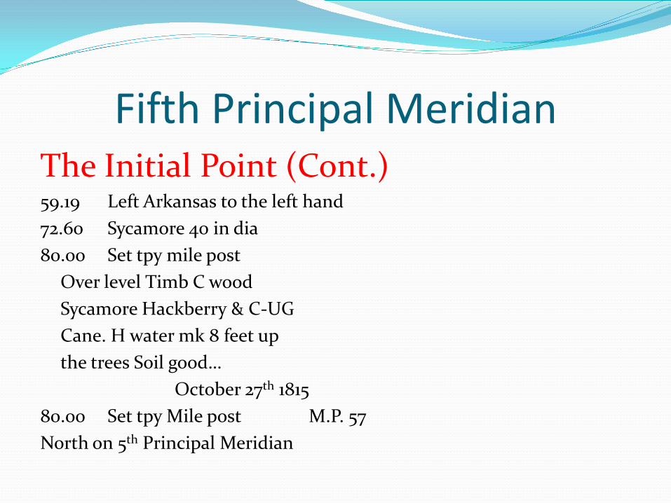
Fifth Principal MeridianThe Initial Point (Cont.)59.19 Left Arkansas to the left hand72.60 Sycamore 40 in dia80.00 Set tpy mile post
Over level Timb C woodSycamore Hackberry & C-UGCane. H water mk 8 feet upthe trees Soil good…
October 27th 181580.00 Set tpy Mile post M.P. 57North on 5th Principal Meridian

Fifth Principal MeridianThe Initial Point (Cont.)30.25 W.O. 12 in dia40.00 Set temp ½ M post in South-
ern edge of a Cypress Swamp60.50 Intersected the Base line 26 miles
& 30 Chains West of the Mississippi where set a Post corner of Sects. 1.6.31 & 36 & Townships 1 & 1 N of the Ranges1 E & 1 West from which a Gum 18 in dia bears N61E dist

Fifth Principal MeridianThe Initial Point (Cont.)
44 lks & a do 18 in dia brs S70W dist10 L-S1/2 M over level 2nd land-T. W & BO – U.g. Same-bkn low & wet – TS Cypress
Nov 10th…

Fifth Principal Meridian

Fifth Principal Meridian

Fifth Principal Meridian

Fifth Principal Meridian

Fifth Principal Meridian

Fifth Principal Meridian

Fifth Principal Meridian
Fifth Principal Meridian

Fifth Principal Meridian

Fifth Principal Meridian

Fifth Principal Meridian

Fifth Principal Meridian
Convergence of meridiansRhumb lines or parallels of latitudeLine of constant bearing vs. line of sightApparent misclosureGrid coordinate systems

Convergence of Meridians Land Ordinance of 1785 “The Surveyors, as they are respectively qualified, shall
proceed to divide the said territory into townships of six miles square, by lines running due north and south, and others crossing these at right angles, as near as may be, unless where the boundaries of the late Indian purchases may render the same impracticable, and then they shall depart from this rule no farther than such particular circumstances may require; and each surveyor shall be allowed and paid at the rate of two dollars for every mile, in length, he shall run, including the wages of chain carriers, markers, and every other expense attending the same.”

Convergence of Meridians True Meridian Public Land Survey directions determined with
reference to the true meridian as defined by the axis of the earth’s rotation.
The true meridian is a line along a meridian of longitude.
Historically the determination of a true meridian has been based on an astronomic observation at the point of record.
There is an angular difference between the astronomic and geodetic direction.

Convergence of Meridians True Meridian (cont.) This angle (the Laplace correction or deflection of the
vertical) is caused by difference in the direction of local gravity as compared with the normal to the reference ellipsoid.
This value has been difficult to determine in the past. Historically the determination of a true meridian has
been based on an astronomic observation at the point of record.
Publication of the NAD 83 allowed the calculation of the Laplace correction to be made

Convergence of Meridians

Convergence of Meridians True Meridian (cont.) In most conventional surveys the application of this
correction is not necessary The application of the Laplace correction may be
necessary on large-scale surveys where geodetic and astronomic observations are mixed.

Rhumb Lines - Parallels of LatitudeRhumb line
A rhumb is a course on the Earth of constant bearing. For example, to travel from New York to London a voyager could head at a constant bearing 73◦ east of north.Loxodrome is a Latin synonym for rhumb, and has come to be used more as a geometric term—the course is a rhumb, the curve is a loxodrome. On a surface of revolution, meridians are copies of the revolved curve; on the earth, they are north-south lines of constant longitude. A loxodrome intersects all the meridians at the same angle. A circle of constant latitude is a loxodrome (perpendicular to meridians).
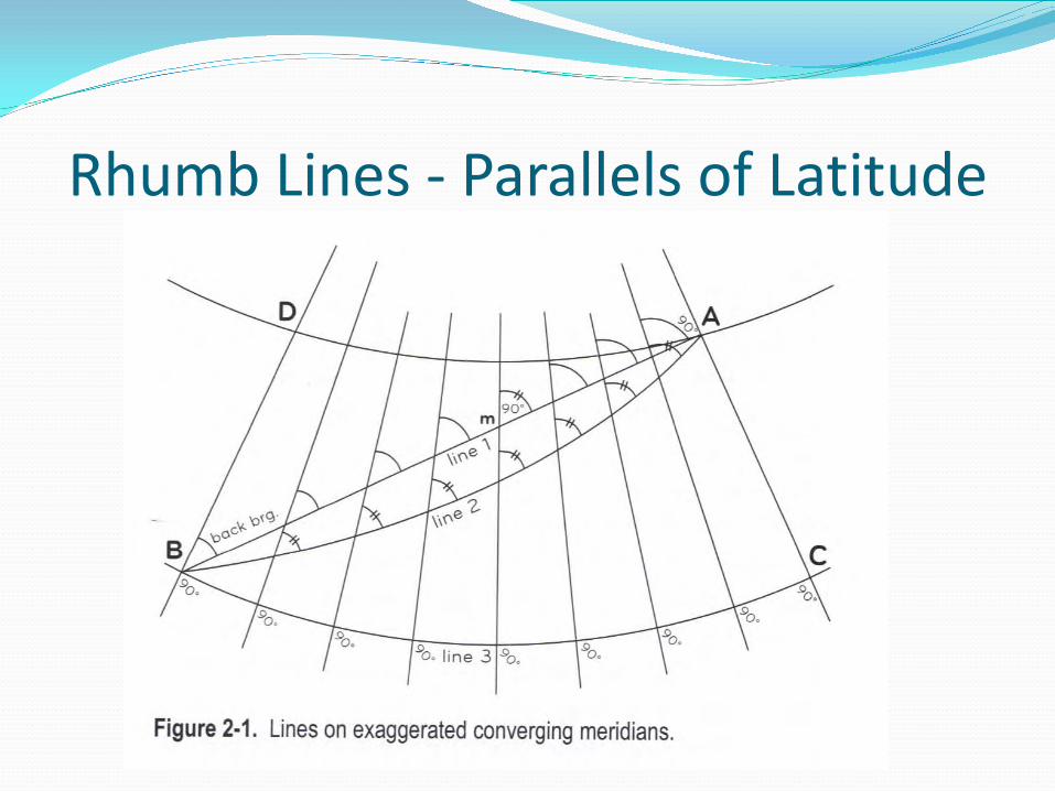
Rhumb Lines - Parallels of Latitude

Rhumb Lines - Parallels of Latitude

Rhumb Lines - Parallels of Latitude

Line of Constant Bearing Straight line
Act of February 11, 1805… to be subdivided into sections, by running straight lines from the mile corners thus marked, to the opposite corresponding corners…
Tiffin’s Instructions, 1815Great care must be taken that the north and south lines be run according to the true meridian as required by law, and east and west lines be run at right angles to them as far as practicable…
Line of Constant Bearing Straight line
Lines of Constant BearingMost lines in the PLSS are intended to be surveyed as lines of constant bearing. This is a direct result of the requirement that the lines be run “according to the true meridian” thereby crossing each meridian at the same angle.Examples of lines of constant bearing:
Base linesStandard ParallelsRandom latitudinal township boundary lines

Line of Constant Bearing Straight line
Lines of Constant Bearing (cont.)Grant linesReservation lines
Lines of constant bearing can be defined as a forward bearing, a reverse bearing and a mean bearing in a rectangular system. This line is from the beginning point to the ending point, and follows the rhumb line.The rate of departure of a line of sight from a true parallel is a function of the latitude on the earth’s surface.

Rhumb Lines - Parallels of Latitude

Line of SightThe line of sight is defined as the shortest distance between two points. Conventional surveying instruments make measurements along the line of sight. This line is a line of constantly changing bearing.A line of sight passes each meridian at a different angle.In the PLSS line of sight lines have a different bearing at each corner point on the line.The line along a meridian is also a line of sight.
Apparent MisclosureThe basis of bearing of the PLSS is not rectangular. Using plane computational methods on the PLSS datum will result in a geometric effect called the apparent misclosure due to meridional convergence. In the PLSS datum, even if all measurements are perfect, there will be an apparent misclosure when using a plane coordinate system. This effect will increase with an increase in latitude. The apparent misclosure is also a function of the area of the figure.

Apparent MisclosureA “cardinal square” having sides that are cardinal north, west, south and east by true mean bearings such as a section having 80.00 chains on a side at 40°N latitude will be shorter by 1.69 links (1.15 feet) on the north line. At 70°N latitude the same figure will be 5.53 links (3.53 feet) shorter.
Grid Coordinate SystemsState plane systems allow surveyors to work in a plane coordinate system over limited areas without significant angular or distance distortions. The Missouri coordinate system of 1983 is based on the Transverse Mercator projection. Arkansas and Kansas both use the Lambert Conformal Conical projections for their state plane coordinate systems. In Missouri there are three state plane zones:
Eastern Zone CM = 90°30’Central Zone CM = 92°30’Western Zone CM = 94°30’

Grid Coordinate SystemsGrid FactorThe grid factor is the conversion for ground distances to grid distances. This is used to place the measured distances on the ground surface onto the grid surface to calculate grid distances and grid coordinates.The grid factor is related to two major components:
Elevation FactorScale Factor
The elevation factor is related to the difference in elevation of the ellipsoid, the geoid and the ground.

Grid Coordinate SystemsThe grid factor is not as sensitive to errors in elevation as it is to errors in the scale factor.

Grid Coordinate Systems

Grid Coordinate SystemsThe scale factor is another component of the grid factor and in the transverse Mercator projection varies with distance from the central meridian for each of the three zones.The grid factor is determined by the multiplying the elevation factor and the scale factor.It is important to understand the use of state plane coordinate systems even though the use of GPS has in some cases simplified the conversion.
Grid Coordinate SystemsMeasurement of DirectionsThe basis of direction in the state plane coordinate system is coordinate grid lines. In the transverse Mercator projection grid north and geodetic north are the same along the central meridian. All grid lines in the plane system are parallel or perpendicular to the central meridian. The true meridians converge and therefore the grid and true meridian only coincide at the central meridian for the zone. The amount that grid north differs from geodetic north is called grid convergence.

Grid Coordinate Systems
Grid Coordinate SystemsAdjustment date
The date of adjustment of the control stations makes a difference in the value of the state plane coordinates. It is also important to understand what adjustment is being used when using RTK GPS even with OPUS and MoDOT VRS.

MONUMENTATION
From the GLO Surveys to Present

MONUMENTATION
Survey monumentation has evolved along what I would call a bell curve
Non-durable Large durable small durable
We will discuss the range of monumentation from the original GLO surveys through the ages to our current monumentation standardswith an interjection of odd and unusual monumentation.

ORIGINAL INSTRUCTIONS
1815 – Instructions for Deputy Surveyors
1831 – Circular from GLO to Surveyor General
1832 – Haywoods Instructions canceling fingerboards and irons
1834 – Instructions to Deputy Surveyors, Illinois & Missouri
1855 – Instructions to Surveyor General of Public Lands
1864 – Instructions to the Surveyor General
1871 – Instructions to the Surveyor General
1881 – Instructions to the Surveyor General

1815 – Edward Tiffin1766-1829
1812 - Appointed by President Madisonas Commissioner of General Land Office
“The posts must be erected at the distance of every mile, and half mile from where the town or sectional line commenced (except a tree may be so situated as to supply the place of a post, which post must be at least three inches diameter and rise not less than three feet...”
...notched on south and east the number of miles from SE corner of twp.
...no marks on 1/2 mile posts
...two bearing trees in opposite directions
...WT's at section corners marked from bottom to top...SEC, TXX, RXX
...WT's at quarter corners marked 1/4S

1/4S Scribing

WOOD POSTS - SUBSEQUENT
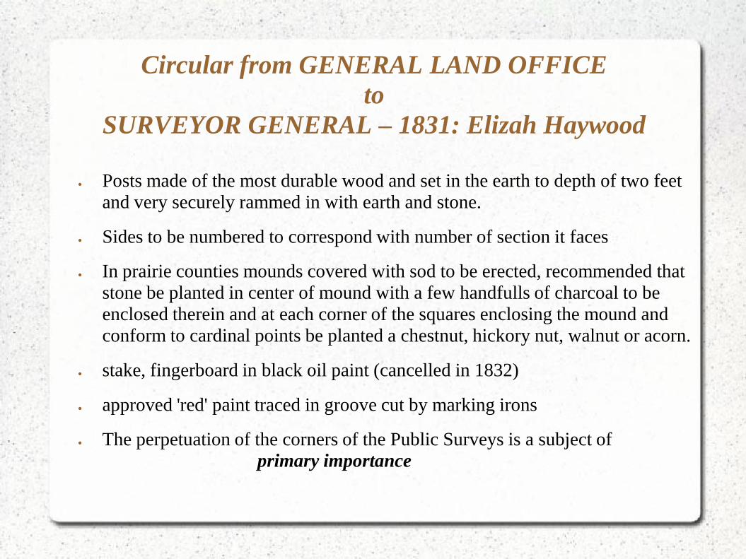
Circular from GENERAL LAND OFFICEto
SURVEYOR GENERAL – 1831: Elizah Haywood
• Posts made of the most durable wood and set in the earth to depth of two feet and very securely rammed in with earth and stone.
• Sides to be numbered to correspond with number of section it faces
• In prairie counties mounds covered with sod to be erected, recommended that stone be planted in center of mound with a few handfulls of charcoal to be enclosed therein and at each corner of the squares enclosing the mound and conform to cardinal points be planted a chestnut, hickory nut, walnut or acorn.
• stake, fingerboard in black oil paint (cancelled in 1832)
• approved 'red' paint traced in groove cut by marking irons
• The perpetuation of the corners of the Public Surveys is a subject of primary importance

Pits & Mound
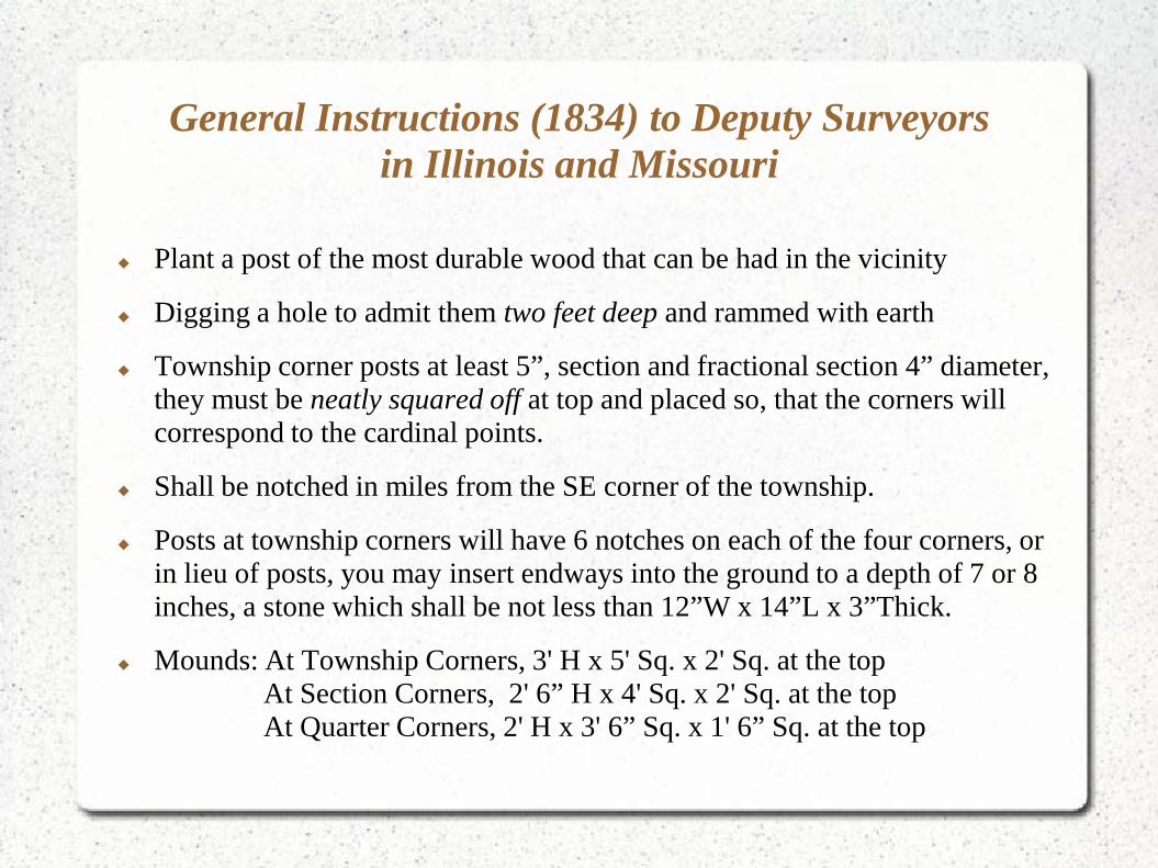
General Instructions (1834) to Deputy Surveyorsin Illinois and Missouri
Plant a post of the most durable wood that can be had in the vicinity
Digging a hole to admit them two feet deep and rammed with earth
Township corner posts at least 5”, section and fractional section 4” diameter, they must be neatly squared off at top and placed so, that the corners will correspond to the cardinal points.
Shall be notched in miles from the SE corner of the township.
Posts at township corners will have 6 notches on each of the four corners, or in lieu of posts, you may insert endways into the ground to a depth of 7 or 8 inches, a stone which shall be not less than 12”W x 14”L x 3”Thick.
Mounds: At Township Corners, 3' H x 5' Sq. x 2' Sq. at the topAt Section Corners, 2' 6” H x 4' Sq. x 2' Sq. at the topAt Quarter Corners, 2' H x 3' 6” Sq. x 1' 6” Sq. at the top

GLO Notes - Mound

General Instructions (1834) to Deputy Surveyorsin Illinois and Missouri
or...deposit at the place of the corner, three stones, not less than five inches square by three inches thick – the top of the uppermost stone to be 3” below the natural surface of the ground....over said stones erect a mound.
or...in lieu of charcoal or stone...insert endways into the ground, and to a depth of 7 or 8 inches, a stone, which shall not be less than 12” wide, 14” long, and 3” thick; over which no mound need be erected...the kind of stone used with its shape and dimensions and the manner in which it is set, must be particularly described in your field notes.
Quarter Section posts (of durable wood) 3” diameter, placed in the ground and marked 1/4S...with two witness trees.

General Instructions (1834) to Deputy Surveyorsin Illinois and Missouri - cont.
In some townships the requirement of stone type and sizing was ignored.
T27N R4WCharles DeWard - 1840

THE $$$$$ ORIGINAL STONE
Original stone recovered at the 11,12,13,14 Section CornerT27N R3W
Original notes 1840 “set a stone”
Position originally proportioned
Stone recovered: Sandstone26”x11”x6” with notches
1838 scribed on stone

Retracement & Extension Survey 1848 – Original Survey
1922 – Retracement andExtension surveys

Extension Survey – 15N 9E
Monumented with iron post, 3 ft. long, 2 ins. diam., 27 ins. in the ground with brass cap mkd....

COUNTY SURVEYORS
Late 1800's – Early 1900's........Stone Age
1930's – 1960's........Whatever was laying around the farm
1964 – Current....Minimum Standards.......rebars, pipes, iron rods

STONE AGE
Set a stone.....no dimensions & dimensioned
Mound of stones
“X” or marks on Boulders
Unique Stones
County Surveyors had unique traits.......

STONE AGE

JUNK IRON AGE
Wagon tire irons, wagon irons, wagon thimbles, plowshares
sucker rods, axles, washing machine wringers
rifle barrels, musket barrels, chaining pins?
Model A engine...

Chaining Pin

Broken Glass, Charcoal Under Stones

JUNK IRON
A collection of iron removed at corners perpetuated with DNR Co-Op Monumentation

STANDARDIZED ERA
First Minimum Standards – Advisory only, November 1964
First promulgated by authority – 1973
Current Minimum Standards - 2003

CURRENT MONUMENTATION STANDARDS
PERMANENT MONUMENTS
Concrete Monuments at least 4” square, no less than 24” longwith stamped brass or aluminum cap.
Commercial cast iron or aluminum markers no less than 24” longnonferrous markers shall have magnets attached
Steel rods not less than 5/8” X 24” with cap, iron pipe markers not less than 3/4” inside diameter with cap.
Brass or aluminum disk not less than 2” diameter countersunk and cemented in drill hole.

CURRENT MONUMENTATION STANDARDS
SEMI-PERMANENT MONUMENTS
Iron pipe markers not less than 3/4” outside diameter, not less than 18” long
Steel rod markers not less than 1/2” x 18” with plastic or alum. cap
Cross-cut or drill hole
In asphalt, RR spikes, cotton picker spindles CPS and other metal devices. PK and concrete nails not to be used

CONCLUSION
Monumentation standards and requirement have transformed from less durable objects such as wooden posts and mounds to large durable objects such as stones, rock mounds, etc. to our current standards of ferrous metals.
Main objective is to establish or perpetuate the corners of the Public Land Survey System to a degree that is the most permanent to be easily recovered by those who follow our footsteps.
BONA FIDE RIGHTS
BONA FIDE - made, done, presented, etc., in good faith; without deception or fraud

BONA FIDE RIGHTS1973 2009
Chapter 6-50Describes conditions that warrant
protection of bona fide rights as to location due to:
1) gross errors in original survey
2) inadequate original evidence
3) complicated conditions, double corners, other conflicting evidence
Chapter 6-53may also vest to local surveys that rely
on original evidence

United States v. Reimann504 F.2d 135
“It would be inequitable to permit the government...to accept a survey,...recording it with knowledge that it would be relied upon by patentees, and then grant the government the right to alter correct its error, ex parte, to the detriment of those who did in fact, and in good faith, rely upon it.”
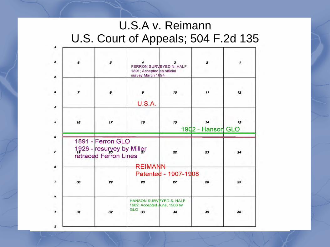
U.S.A v. ReimannU.S. Court of Appeals; 504 F.2d 135

Spanish Land Grants Represent some of earliest land transactions and
establishment of title....from late 1600's to 1803.
1805 – Congress passed legislation establishing rules and procedures for titles to be confirmed or unconfirmed by appointed land commissioners.
Claims established after October 1, 1800 were not recognized

GLO NOTES - 1842 - OOPS!

Grant Survey - 1819
Grant survey of 2000 arpens
“No. 2415, surveyed for John B. DePlace, who claims in his own right 2000 arpens, equal to 1701 4/100 acres.

1840 – GLO Plat
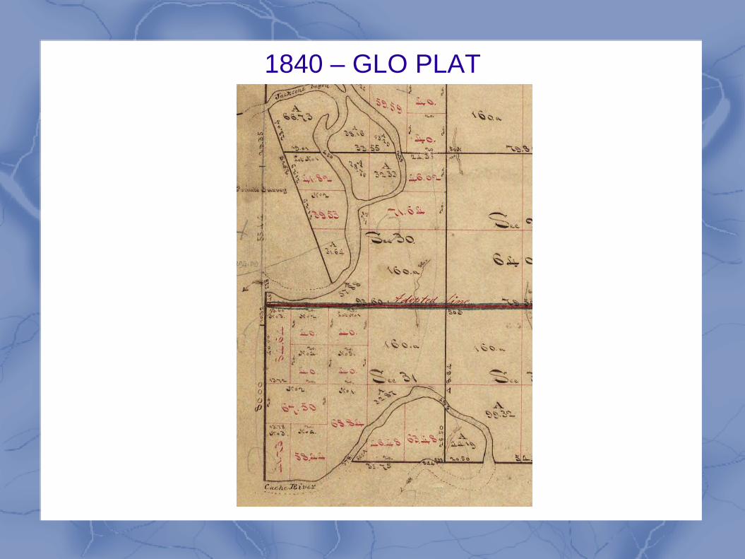
1840 – GLO PLAT

New Madrid Claims
Established by Act of Congress in February of 1815
Direct result of New Madrid earthquake of 1812
Those “materially injured” could relocate to other unclaimed land in territory free of charge.
Could not claim greater than what they previously owned
Not to exceed 640 acres
Those that owned less than 160 acres could claim up to 160 ac.

New Madrid Claim

Bona Fide Rights - conculsion
Protecting....that which was made, done, presented, etc., in good faith; without deception or fraud
Knight v.United States Land Association, 142 US 161,181 (1891)“It is obvious...that in the administration of such large and varied interests as are intrusted to the Land Department, matters not foreseen, equities not anticipated, and which are, therefore, not provided for by express statute, may sometimes arise, and, therefore, that the Secretary of the Interior is given that...power which will enable him, in the face of these unexpected contingencies, to do justice...” (2009 BLM Manual)
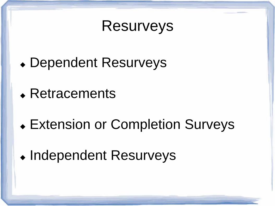
Resurveys
Dependent Resurveys
Retracements
Extension or Completion Surveys
Independent Resurveys

Dependent Resurvey
1973 – Chapter 6-4designed to restore the original conditions of the official survey according to the record.
2009 – Chapter 5-10...is a retracement and reestablishment of the lines of the original survey or of a prior resurvey in their true original positions according to the best available evidence of the original corners...In legal contemplation and in fact, the lands contained in a certain section of the original survey and the lands contained in the corresponding section of the dependent resurvey are identical.

Dependent Resurvey
Not fixing (repairing)
Not moving
Not shifting
Is a reconstruction of the prior original survey (or resurvey)
Original GLO corners are the true corners
Congressional Act of 1805...”GLO corners are true cornersand the distances on the plat are the true lengths of thelines.”
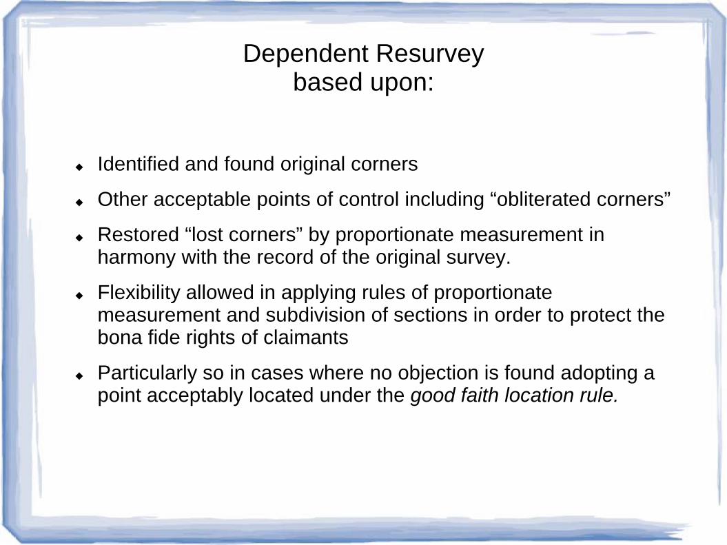
Dependent Resurveybased upon:
Identified and found original corners
Other acceptable points of control including “obliterated corners”
Restored “lost corners” by proportionate measurement in harmony with the record of the original survey.
Flexibility allowed in applying rules of proportionate measurement and subdivision of sections in order to protect the bona fide rights of claimants
Particularly so in cases where no objection is found adopting a point acceptably located under the good faith location rule.

Original Survey – T29N R4E

Dependent Resurvey T29N R4E
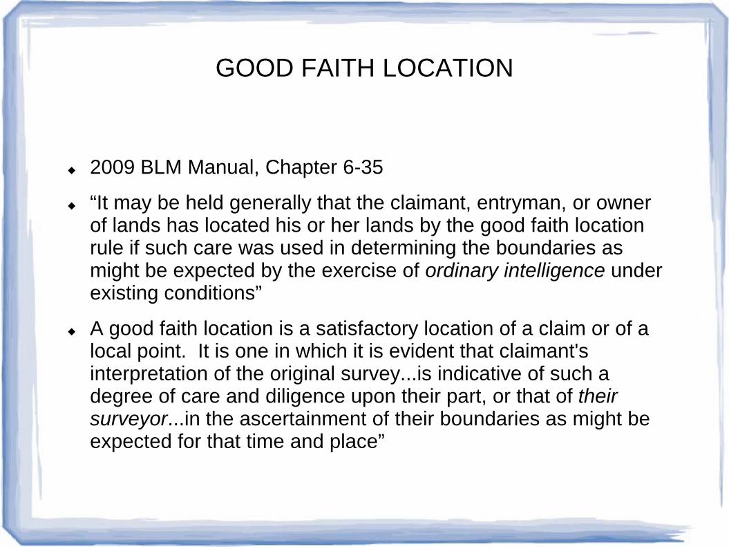
GOOD FAITH LOCATION
2009 BLM Manual, Chapter 6-35
“It may be held generally that the claimant, entryman, or owner of lands has located his or her lands by the good faith location rule if such care was used in determining the boundaries as might be expected by the exercise of ordinary intelligence under existing conditions”
A good faith location is a satisfactory location of a claim or of a local point. It is one in which it is evident that claimant's interpretation of the original survey...is indicative of such a degree of care and diligence upon their part, or that of their surveyor...in the ascertainment of their boundaries as might be expected for that time and place”

GOOD FAITH LOCATION
The surveyor should neither rigidly apply the rules for restoration of lost corners ...without regard to effect on location of improvements....nor accept the position of improvements without question regardless of their relation or irrelation to existing evidence of the original survey...
Between these extremes will be found the basis for determination.
No definite specific set of rules can be laid down in advance. The solution to the problem must be found on the ground by the surveyor.
The responsibility to resolve the question of good faith as to location rests primarily upon the surveyor's judgement...
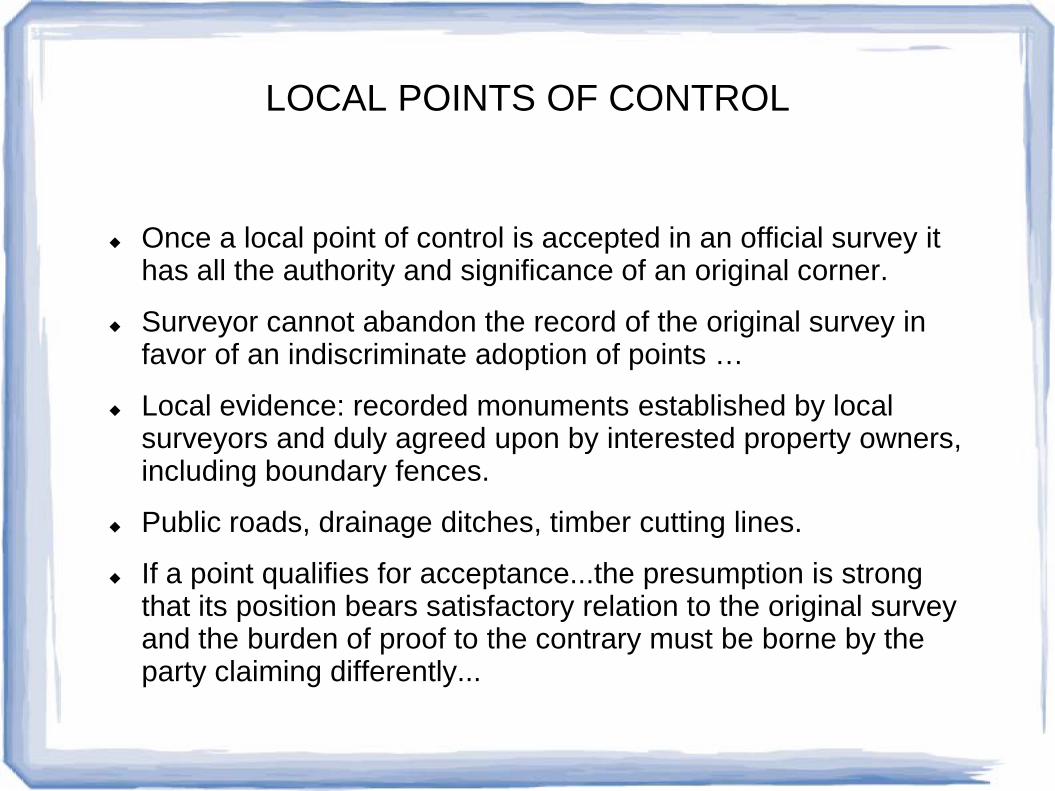
LOCAL POINTS OF CONTROL
Once a local point of control is accepted in an official survey it has all the authority and significance of an original corner.
Surveyor cannot abandon the record of the original survey in favor of an indiscriminate adoption of points …
Local evidence: recorded monuments established by local surveyors and duly agreed upon by interested property owners, including boundary fences.
Public roads, drainage ditches, timber cutting lines.
If a point qualifies for acceptance...the presumption is strong that its position bears satisfactory relation to the original survey and the burden of proof to the contrary must be borne by the party claiming differently...

RETRACEMENT SURVEYS
Made to ascertain direction and length of lines and identify monuments and other marks of an established prior survey
If no intervening corners are reestablished, the direct connection between the two corners is reported as a tie.
Made to afford new evidence of the character and condition of the previous survey.
Recovered corners are rehabilitated “refurbished” but does not include restoration of lost corners.
The retracement is sometimes complete in itself, but usually is made as an early part of a resurvey.

EXTENSION or COMPLETION SURVEYSFederal
Only parts of townships or sections were surveyed originally
Mainly due to unusable lands
New townships constructed with protracted as surveyed sections(has been abandoned as unsatisfactory...)
Protracted as surveyed done in Alaska to accommodate Alaska Native Claims Settlement Act...dashed lines on plat indicate which lines not run and marked
Tract “A” townships in Alaska – minimum 2 mile monumentation

Extension Surveys - Missouri
Chapter 241 RSMO, Swamplands, Islands and Abandoned Riverbeds
Occurred mainly along bodies of water, Missouri River, etc.
Authority by Swamp Land Act of Sept. 28, 1850
Lands donated to County where situated
Secretary of State to supply County Clerks with approved list of swamplands in each county.
Patents issued from State of Missouri to Counties
County commissions have full power to sell and dispose of

Extension Surveys - Missouri
County commission issues patent to purchaser...net proceeds of sale to the county school fund.
Land to be surveyed how...Surveyor shall connect the survey with some established section, quarter section, meander or other US survey corner near or adjacent.
Shall subdivide land into sections and quarter sections by producing and extending the lines of the US surveys.

Extension Surveys - Examples

Retracement of Extension Survey

GLO – T50N R18W Howard County, MO

Dependent Resurvey – T50N R18W

INDEPENDENT RESURVEYS2009 Manual – Chapter 5-12
Retracement and reestablishment in reliance on evidence of the original survey in order to give official recognition and respect to all alienated lands with its scope...
Includes establishment of new section lines, township lines...independent of and without reference to the corners of the original survey.
...necessary to preserve the boundaries of those lands previously alienated by legal subdivision of the sections in the original survey.
this is done by surveying them as tracts, or conforming the alienated lands to the subdivision of the resurvey...if suitable.
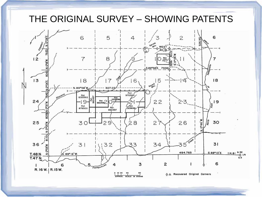
THE ORIGINAL SURVEY – SHOWING PATENTS

THE INDEPENDENT RESURVEY

Resurveys - conclusion
Dependent Resurvey-Relies on original survey throughout-Majority of what we do today
Retracement Survey-Shows ties between existing corners-No corners reestablished...only rehabilitated
Completion or Extension Surveys-Relies on original survey for origin-Creates additional lands in sections or entirely new sections
Independent Resurveys-Relies on original survey for exterior bounds-Protects prior patents and bona fide rights

Existent, Obliterated and Lost CornersTopographic CallsLine TreesCollateral evidence

EvidenceExistent, Obliterated and Lost Corners
Existent CornersAn existent corner is one whose original position can be identified by substantial evidence of the monument or its accessories by reference to the description in the field notes, or located by an acceptable supplemental survey record, some physical evidence, or reliable testimony. 2009 BLM manual: Substantial evidence is more than a scintilla of evidence but less than a preponderance of the evidence.
EvidenceExistent, Obliterated and Lost Corners
Existent Corners (cont.)The evidence should be looked in light of:
(1) The charter and dimensions of the monument in evidence should not be widely different from the record.(2) The markings in evidence should not be inconsistent with the record.(3) The nature of the accessories in evidence, including size, position and markings, should not be greatly at variance with the record.Keep in mind:(1) Allowance for ordinary discrepancies(2) Look for patterns of discrepancies.

EvidenceExistent, Obliterated and Lost Corners
Existent Corners (cont.)(3) Evidence of less than workmanlike care in the original survey in compiling the record.
Erroneously recorded dimensionsTransposed or interchangeable directions or distancesMisidentified tree species or monument typeInconsistencies in reporting topographical features
No set rules can be set down as to what is sufficient evidence.All means should be exhausted in regard to restoring the corner.

EvidenceExistent, Obliterated and Lost Corners
Obliterated CornerAn obliterated corner is an existent corner where at the corner’s original position, there are no remaining traces of the monument or accessories, but at whose position has been perpetuated, or the point for which may be recovered, by substantial evidence from the acts or reliable testimony of the interested landowners, competent surveyors, other qualified local authorities, or witnesses, or by some acceptable record evidence.
An obliterated corner position can be proven by substantial direct or collateral evidence. When there is both direct and collateral evidence the direct evidence will be given more weight.

EvidenceExistent, Obliterated and Lost Corners
Lost CornerOnly when every means of identifying the original position of a corner has been exhausted shall a corner be considered to be lost. A lost corenr is one whose original position cannot be determined by substantial evidence, either from traces of the original marks or from acceptable evidence or reliable testimony that bears upon the original position and whose location can be restored only by reference to one or more independent corners.
If substantial evidence of the position of the original corner exists, it is an existent or obliterated corner. If the corner is truly lost then it must be properly reestablished.

EvidenceTopographic Calls
Topographic CallsThe proper use of topographic calls of the original field notes may assist in recovering the locus of the original corner. This evidence my merely disprove other questionable features of be a valuable guide in arriving at the immediate vicinity of a line or corner. At best a topographic call or calls can verify or disprove questionable evidence of the original monument or its accessories. In rare cases, they may serve as substantial evidence to fix the position of a point, line or corner.Topographic calls may be poorly recorded or fabricated.

EvidenceLine Trees
Line TreesUnder the law (federal and Missouri), a definitely identified line tree with the distinguishing marks is a monument of the original survey. It is properly used as a control point in the reestablishment of lost corners by the appropriate method of proportionate measurement and treated as a recovered corner. It becomes an angle point on the true line.Problems can arise where line trees were improperly established on a random line and recorded in the field notes rather than on the true line. Having said this, the most probable location of the true line is on a straight line between the corners.
EvidenceCollateral Evidence
Collateral EvidenceIt is generally held that the claimant, entryman, of owner of lands has located his or her lands by the good faith location rule if such care was used in determining the boundaries as might be expected by the exercise of ordinary intelligence under existing conditions. Local monuments must be analyzed for good faith location. Lack of good faith is not necessarily chargeable if the entryman has not located himself according to a rigid application of the rules laid down for the restoration of lost corners where:
Complicated conditions involve a double set of corners, both of which may be regarded as authentic.
There are no existing corners in one or more directions for an extensive distance.

EvidenceCollateral Evidence
Collateral Evidence (cont.)Existing marks are improperly related to an extraordinary degree.All evidence of the original survey or prior resurvey that have
been adopted by the entryman as a basis for his or her location have been lost before the resurvey is undertaken.
Acceptance of a local point by neighboring claimants used for the control of the location of claims very often carries with it the necessity for a consideration of its influence in the matter of the acceptability of such locations under the good faith rule.


![PROFESSIONAL AND TECHNICAL SURVEYORS’ ACT 40 OF 1984 · [Short title, formerly “Professional Land Surveyors’ and Technical Surveyors’ Act” amended by s. 25 of Act 34/93]](https://static.fdocuments.net/doc/165x107/5f8dacbd393b8f550769f416/professional-and-technical-surveyorsa-act-40-of-short-title-formerly-aoeprofessional.jpg)