MISSILE DEFENSE AGENCY (MDA) SMALL BUSINESS … · MISSILE DEFENSE AGENCY (MDA) SMALL BUSINESS...
124
MDA - 1 MISSILE DEFENSE AGENCY (MDA) SMALL BUSINESS INNOVATION RESEARCH PROGRAM (SBIR) SBIR 04.4 Proposal Submission Instructions INTRODUCTION The MDA SBIR program is implemented, administrated and managed by the MDA Office of Small and Disadvantaged Business Utilization (SADBU). If you have any questions regarding the administration of the MDA SBIR program please call 1-800-WIN-BMDO. Additional information on the MDA SBIR Program can be found on the MDA SBIR home page at http://www.winmda.com/ . Information regarding the MDA mission and programs can be found at http://www.acq.osd.mil/bmdo . For general inquiries or problems with the electronic submission, contact the DoD Help Desk at 1-866-724-7457 (1- 866-SBIRHLP) (8am to 5pm EST). For technical questions about the topic during the pre-solicitation period (2 Aug 2004 through 14 Sept 2004), contact the Topic Authors listed under each topic on the http://www.dodsbir.net website before COB 14 Sept 2004. As funding is limited, MDA will select and fund only those proposals considered to be superior in overall technical quality and most critical. MDA may fund more than one proposal in a specific topic area if the technical quality of the proposal is deemed superior, or it may fund no proposals in a topic area. PHASE I GUIDELINES MDA intends for Phase I to be only an examination of the merit of the concept or technology that still involves technical risk, with a cost not exceeding $100,000. A list of the topics currently eligible for proposal submission is included in this section followed by full topic descriptions. These are the only topics for which proposals will be accepted at this time. The topics originated from the MDA Programs and are directly linked to their core research and development requirements. Please assure that your e-mail address listed in your proposal is current and accurate. MDA cannot be responsible for notification to companies that change their mailing address, their e-mail address, or company official after proposal submission. Phase I Proposal Submission Read the DoD front section of this solicitation for detailed instructions on proposal format and program requirements . When you prepare your proposal submission, keep in mind that Phase I should address the feasibility of a solution to the topic. Only UNCLASSIFIED proposals will be entertained. MDA accepts Phase I proposals not exceeding $100,000. The technical period of performance for the Phase I should be 6 months. MDA will evaluate and select Phase I proposals using scientific review criteria based upon technical merit and other criteria as discussed in this solicitation document. Due to limited funding, MDA reserves the right to limit awards under any topic and only proposals considered to be of superior quality will be funded. If you plan to employ NON-U.S. Citizens in the performance of a MDA SBIR contract, please identify these individuals in your proposal as specified in Section 3.5.b (7) of the program solicitation. It is mandatory that the ENTIRE technical proposal, DoD Proposal Cover Sheet, Cost Proposal, and the Company Commercialization Report are submitted electronically through the DoD SBIR website at http://www.dodsbir.net/submission . If you have any questions or problems with the electronic proposal submission contact the DoD SBIR Helpdesk at 1-866-724-7457. This COMPLETE electronic proposal submission includes the submission of the Cover Sheets, Cost Proposal, Company Commercialization Report, the ENTIRE technical proposal and any appendices via the DoD Submission
Transcript of MISSILE DEFENSE AGENCY (MDA) SMALL BUSINESS … · MISSILE DEFENSE AGENCY (MDA) SMALL BUSINESS...

MDA - 1
MISSILE DEFENSE AGENCY (MDA)
SMALL BUSINESS INNOVATION RESEARCH PROGRAM (SBIR) SBIR 04.4 Proposal Submission Instructions
INTRODUCTION The MDA SBIR program is implemented, administrated and managed by the MDA Office of Small and Disadvantaged Business Utilization (SADBU). If you have any questions regarding the administration of the MDA SBIR program please call 1-800-WIN-BMDO. Additional information on the MDA SBIR Program can be found on the MDA SBIR home page at http://www.winmda.com/. Information regarding the MDA mission and programs can be found at http://www.acq.osd.mil/bmdo. For general inquiries or problems with the electronic submission, contact the DoD Help Desk at 1-866-724-7457 (1-866-SBIRHLP) (8am to 5pm EST). For technical questions about the topic during the pre-solicitation period (2 Aug 2004 through 14 Sept 2004), contact the Topic Authors listed under each topic on the http://www.dodsbir.net website before COB 14 Sept 2004. As funding is limited, MDA will select and fund only those proposals considered to be superior in overall technical quality and most critical. MDA may fund more than one proposal in a specific topic area if the technical quality of the proposal is deemed superior, or it may fund no proposals in a topic area. PHASE I GUIDELINES MDA intends for Phase I to be only an examination of the merit of the concept or technology that still involves technical risk, with a cost not exceeding $100,000. A list of the topics currently eligible for proposal submission is included in this section followed by full topic descriptions. These are the only topics for which proposals will be accepted at this time. The topics originated from the MDA Programs and are directly linked to their core research and development requirements. Please assure that your e-mail address listed in your proposal is current and accurate. MDA cannot be responsible for notification to companies that change their mailing address, their e-mail address, or company official after proposal submission. Phase I Proposal Submission Read the DoD front section of this solicitation for detailed instructions on proposal format and program requirements. When you prepare your proposal submission, keep in mind that Phase I should address the feasibility of a solution to the topic. Only UNCLASSIFIED proposals will be entertained. MDA accepts Phase I proposals not exceeding $100,000. The technical period of performance for the Phase I should be 6 months. MDA will evaluate and select Phase I proposals using scientific review criteria based upon technical merit and other criteria as discussed in this solicitation document. Due to limited funding, MDA reserves the right to limit awards under any topic and only proposals considered to be of superior quality will be funded. If you plan to employ NON-U.S. Citizens in the performance of a MDA SBIR contract, please identify these individuals in your proposal as specified in Section 3.5.b (7) of the program solicitation. It is mandatory that the ENTIRE technical proposal, DoD Proposal Cover Sheet, Cost Proposal, and the Company Commercialization Report are submitted electronically through the DoD SBIR website at http://www.dodsbir.net/submission. If you have any questions or problems with the electronic proposal submission contact the DoD SBIR Helpdesk at 1-866-724-7457. This COMPLETE electronic proposal submission includes the submission of the Cover Sheets, Cost Proposal, Company Commercialization Report, the ENTIRE technical proposal and any appendices via the DoD Submission
MDA - 2
site. The DoD proposal submission site http://www.dodsbir.net/submission will lead you through the process for submitting your technical proposal and all of the sections electronically. Each of these documents are submitted separately through the website. Your proposal submission must be submitted via the submission site on or before the 6 a.m.15 October 2004 deadline. Proposal submissions received after the closing date will not be processed. PHASE II GUIDELINES This solicitation solicits Phase I Proposals. MDA makes no commitments to any offeror for the invitation of a Phase II Proposal. Phase II is the prototype/demonstration of the technology that was found feasible in Phase I. Only those successful Phase I efforts that are invited to submit a Phase II proposal will be eligible to submit a Phase II proposal. Invitations to submit a Phase II proposal will be made by the MDA SBIR Program Manager (PM). Phase II proposals may be submitted for an amount normally not to exceed $750,000. MDA will consider making Phase II Invitations with a base program of $750K and options. The base Program and options, together, may total a maximum of $2,500K. PHASE II PROPOSAL INVITATION An SBIR Topic Sponsor (either an MDA Element MDA Project Office or MDA Functional Area Office) begins the process for a Phase II Invitation by reviewing the Phase I work of each contractor (along with the Contract Technical Monitor) and making a recommendation on what Phase I efforts should continue into Phase II. The MDA Sponsor recommendation is based on several criteria. The Phase II Prototype/Demonstration (What is being offered at the end of Phase II?), Phase II Benefits/Capabilities (Why it is important), Phase II Program Benefit (Why it is important to an MDA Program), Phase II Partnership (Who are the partners and what are their commitment? Funding? Facilities? Etc? This also can include Phase III partners), and the Potential Phase II Cost. This is the basic business case for a Phase II invitation and requires communication between the MDA Program, the Phase I SBIR Offeror, and the Phase I Technical Monitor. An MDA SBIR Working Group then reviews the entire Phase II Invitation list and forwards their recommendations to the MDA Source Selection Authority for final approval. PHASE II PROPOSAL SUBMISSION If you have been invited to submit a Phase II proposal, please see the MDA SBIR website http://www.winmda.com/ for further instructions. All Phase II proposals must have a complete electronic submission. Complete electronic submission includes the submission of the Cover Sheets, Cost Proposal, Company Commercialization Report, the ENTIRE technical proposal and any appendices via the DoD Submission site. The DoD proposal submission site http://www.dodsbir.net/submission will lead you through the process for submitting your technical proposal and all of the sections electronically. Each of these documents are submitted separately through the website. Your proposal must be submitted via the submission site on or before the MDA specified deadline or may be declined. MDA FASTTRACK: MDA does not have a FastTrack Program. MDA does encourage, but does not require, partnership and outside investment as part of discussions with MDA Sponsors for potential Phase II invitation. MDA SBIR PHASE II ENHANCEMENT PROGRAM To encourage transition of SBIR into DoD Systems, MDA has a Phase II Enhancement policy. While not guaranteed, MDA may consider a limited number of Phase II enhancements on a case-by-case basis. MDA will generally provide the additional Phase II enhancement funds by modifying the Phase II contract.

MDA - 3
PHASE I PROPOSAL SUBMISSION CHECKLIST: All of the following criteria must be met or your proposal will be REJECTED. ____1. Your technical proposal, the DoD Proposal Cover Sheet, the DoD Company Commercialization
Report (required even if your firm has no prior SBIRs), and the Cost Proposal have been submitted electronically through the DoD submission site by 6 a.m. 15 October 2004.
____2. The Phase I proposed cost does not exceed $100,000.
MDA - 4
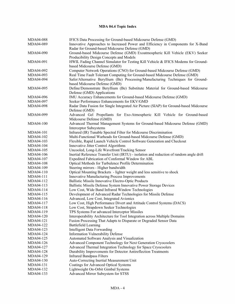
MDA 04.4 Topic Index MDA04-088 IFICS Data Processing for Ground-based Midcourse Defense (GMD) MDA04-089 Innovative Approaches to Increased Power and Efficiency in Components for X-Band
Radar for Ground-based Midcourse Defense (GMD) MDA04-090 Ground-based Midcourse Defense (GMD) Exoatmospheric Kill Vehicle (EKV) Seeker
Producibility Design Concepts and Models MDA04-091 HWIL Fading Channel Simulator for Testing Kill Vehicle & IFICS Modems for Ground-
based Midcourse Defense (GMD) MDA04-092 Computer Network Operations (CNO) for Ground-based Midcourse Defense (GMD) MDA04-093 Real Time Fault Tolerant Computing for Ground-based Midcourse Defense (GMD) MDA04-094 Safer/Alternative Beryllium (Be) Processing/Manufacturing Techniques for Ground-
based Midcourse Defense (GMD) MDA04-095 Define/Demonstrate Beryllium (Be) Substitute Material for Ground-based Midcourse
Defense (GMD) Applications MDA04-096 IMU Accuracy Enhancements for Ground-based Midcourse Defense (GMD) MDA04-097 Seeker Performance Enhancements for EKV/GMD MDA04-098 Radar Data Fusion for Single Integrated Air Picture (SIAP) for Ground-based Midcourse
Defense (GMD) MDA04-099 Advanced Gel Propellants for Exo-Atmospheric Kill Vehicle for Ground-based
Midcourse Defense (GMD) MDA04-100 Advanced Thermal Management Systems for Ground-based Midcourse Defense (GMD)
Interceptor Subsystems MDA04-101 Infrared (IR) Tunable Spectral Filter for Midcourse Discrimination MDA04-102 Multi-Functional Warheads for Ground-based Midcourse Defense (GMD) MDA04-103 Flexible, Rapid Launch Vehicle Control Software Generation and Checkout MDA04-104 Innovative Jitter Control Algorithms MDA04-105 Uncooled, Long-Life Wavefront/Tracking Sensor MDA04-106 Inertial Reference Transfer Unit (IRTU) - isolation and reduction of random angle drift MDA04-107 Expedited Fabrication of Conformal Window for ABL MDA04-108 Optical Methods for Turbulence Profile Determination MDA04-109 Steering mirrors - Higher bandwidth MDA04-110 Optical Mounting Brackets - lighter weight and less sensitive to shock MDA04-111 Innovative Manufacturing Process Improvements MDA04-112 Ballistic Missile Innovative Electro-Optic Products MDA04-113 Ballistic Missile Defense System Innovative Power Storage Devices MDA04-114 Low Cost, Wide Band Infrared Window Technologies MDA04-115 Development of Advanced Radar Technologies for Missile Defense MDA04-116 Advanced, Low Cost, Integrated Avionics MDA04-117 Low Cost, High Performance Divert and Attitude Control Systems (DACS) MDA04-118 Low Cost, Strapdown Seeker Technologies MDA04-119 TPS Systems For advanced Interceptor Missiles MDA04-120 Interoperability Architecture for Tool Integration across Multiple Domains MDA04-121 Fusion Processing That Adapts to Disparate or Degraded Sensor Data MDA04-122 Battlefield Learning MDA04-123 Intelligent Data Forwarding MDA04-124 Information Vulnerability Defense MDA04-125 Automated Software Analysis and Visualization MDA04-126 Advanced Component Technology for Next Generation Cryocoolers MDA04-127 Advanced Thermal Integration Technology for Space Cryocoolers MDA04-128 Durability Improvements for Detector Antireflection Treatments MDA04-129 Infrared Bandpass Filters MDA04-130 Auto-Correcting Inertial Measurement Unit MDA04-131 Coatings for Advanced Optical Systems MDA04-132 Lightweight On-Orbit Gimbal Systems MDA04-133 Advanced Mirror Subsystem for STSS
MDA - 5
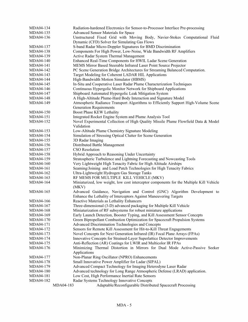
MDA04-134 Radiation-hardened Electronics for Sensor-to-Processor Interface Pre-processing MDA04-135 Advanced Sensor Materials for Space MDA04-136 Unstructured Fixed Grid with Moving Body, Navier-Stokes Computational Fluid
Dynamic (CFD) Solver for Simulating Gas Flows MDA04-137 S-band Radar Micro-Doppler Signatures for BMD Discrimination MDA04-138 Components For High Power, Low-Noise, Wide Bandwidth RF Amplifiers MDA04-139 Active Radar System Thermal Management MDA04-140 Enhanced Real-Time Components for HWIL Ladar Scene Generation MDA04-141 MEMS Mirror Based Steerable Infrared Laser Point Source Projector MDA04-142 PC Scene Generation Bridge Architectures for Streaming Balanced Computation. MDA04-143 Target Modeling for Coherent LADAR HIL Applications MDA04-144 High-Bandwidth Motion Simulator (HBMS) MDA04-145 In-Situ and Cooperative Laser Radar Plume Characterization Techniques MDA04-146 Continuous Hypergolic Monitor Network for Shipboard Applications MDA04-147 Shipboard Automated Hypergolic Leak Mitigation System MDA04-148 A High-Altitude Plume-Hard Body Interaction and Signature Model MDA04-149 Atmospheric Radiance Transport Algorithms to Efficiently Support High-Volume Scene
Generation Requirements MDA04-150 Boost Phase KEW Lethality MDA04-151 Integrated Rocket Engine System and Plume Analysis Tool MDA04-152 Novel Experimental Collection of High Quality Missile Plume Flowfield Data & Model
Validation MDA04-153 Low-Altitude Plume Chemistry Signature Modeling MDA04-154 Simulation of Stressing Optical Clutter for Scene Generation MDA04-155 3D Radar Imaging MDA04-156 Distributed Battle Management MDA04-157 CSO Resolution MDA04-158 Hybrid Approach to Reasoning Under Uncertainty MDA04-159 Stratospheric Turbulence and Lightning Forecasting and Nowcasting Tools MDA04-160 Very Lightweight High Tenacity Fabric for High Altitude Airships MDA04-161 Seaming/Joining and Load Patch Technologies for High Tenacity Fabrics MDA04-162 Ultra-Lightweight Hydrogen Gas Storage Tanks MDA04-163 RF MEMS FOR MULTIPLE KILL VEHICLE (MKV) MDA04-164 Miniaturized, low weight, low cost interceptor components for the Multiple Kill Vehicle
(MKV) MDA04-165 Advanced Guidance, Navigation and Control (GNC) Algorithm Development to
Enhance the Lethality of Interceptors Against Maneuvering Targets MDA04-166 Reactive Materials as Lethality Enhancers MDA04-167 Three-dimensional (3-D) advanced packaging for Multiple Kill Vehicle MDA04-168 Miniaturization of RF subsystems for robust miniature applications MDA04-169 Early Launch Detection, Booster Typing, and Kill Assessment Sensor Concepts MDA04-170 Green Bipropellant Combustion Optimization for Spacecraft Propulsion Systems MDA04-171 Advanced Discrimination Technologies and Concepts MDA04-172 Sensors for Remote Kill Assessment for Hit-to-Kill Threat Engagements MDA04-173 Novel Concepts for Next Generation Infrared (IR) Focal Plane Arrays (FPAs) MDA04-174 Innovative Concepts for Strained-Layer Superlattice Detector Improvements MDA04-175 Anti-Reflection (AR) Coatings for LWIR and Multicolor IR FPAs MDA04-176 Minimizing Thermal Distortion in Mirrors for Dual Mode Active-Passive Seeker
Applications MDA04-177 Non-Planar Ring Oscillator (NPRO) Enhancements MDA04-178 Small Innovative Power Amplifier for Ladar (SIPAL) MDA04-179 Advanced Compact Technology for Imaging Heterodyne Laser Radar MDA04-180 Advanced technology for Long Range Atmospheric Defense (LRAD) application. MDA04-181 Low Cost, High Performance Inertial Rate Sensors MDA04-182 Radar Systems Technology Innovative Concepts
MDA04-183 Adaptable/Reconfigurable Distributed Spacecraft Processing
MDA - 6
MDA 04.4 Topic Descriptions MDA04-088 TITLE: IFICS Data Processing for Ground-based Midcourse Defense (GMD) TECHNOLOGY AREAS: Information Systems, Materials/Processes, Sensors, Battlespace ACQUISITION PROGRAM: MDA/GM OBJECTIVE: Increase the probability of mission success by the In-Flight Interceptor Communication System (IFICS) under adverse conditions by utilizing Fault Predictive Maintenance Techniques, and by implementing Rapid and Reliable Software Insertion. DESCRIPTION: Communications terminals are often deployed as unmanned facilities in regions subject to extreme weather conditions. Antenna positioning machinery, processing hardware, and environmental control subsystems in a terminal must perform reliably, over long periods of time and with minimal unscheduled maintenance, to assure mission success. Ability to predict potential future component faults and respond in advance can significantly enhance the terminal availability. The objective of the project is to develop and demonstrate model-based predictive equipment health monitoring and evaluation techniques for unmanned communications terminals based on advanced signal analysis and model-based trend evaluation methods. In conjunction with the Predictive Maintenance, reliable and accurate methods of revising and downloading operational software are required while minimizing potential down-time. More automated and accurate methods of performing software development are sought along with the complementary effort of software verification and validation. The development procedure from system requirement, code generation, verification, validation, and installation must be seamless. PHASE I: Conduct research and experimental efforts to demonstrate proof-of-principle of the proposed hardware/ software/ firmware technology development strategy. Develop and evaluate architecture for predictive equipment evaluation and reliable software insertion for a remote communications terminal. Provide a report documenting the design, trade analysis and results. Identify and report performance improvements over current state-of-the-art. PHASE II: Develop and test the predictive evaluation and software insertion techniques applicable to an MDA remote communications terminal, including monitoring hardware and interfaces, monitoring and signal conditioning software, evaluation software for use with the terminal automated fault detection/fault isolation software, software development, automated software verification and validation, and seamless insertion. PHASE III: Insert this technology into future Ballistic Missile Defense systems such as the Ground Based Missile Defense System. Adapt this technology to commercial markets. PRIVATE SECTOR COMMERCIAL POTENTIAL: The technology may have commercial and industrial application in remote cell phone site operations. REFERENCES: 1. M. Lebold and M. Thurston, "Open Standards for Condition-Based Maintenance and Prognostic Systems," Maintenance and Reliability Conference (MARCON), Gatlinburg, TN, May 6-9 2001. 2. K. Reichard, M. Van Dyke, and K. Maynard, "Application of Sensor Fusion and Signal Classification Techniques in a Distributed Machinery Condition Monitoring System," Proceedings of SPIE, Volume 4051, April 25-28, 2000, pp 329-336. 3. D. R. Wallace, L. M. Ippolito and B. Cuthill, “Reference Information for the Software Verification and Validation Process,” NIST Special Publication 500-234, Mar 1996. KEYWORDS: Prognostics; Condition-Based Maintenance; Model-Based Evaluation; Qualitative Reasoning; Statistical Pattern Recognition, Software Verification and Validation, Seamless Software Insertion. TPOC: Aaron Corder Phone: (256) 313-9229 Fax: (256) 313-9868 Email: [email protected]
MDA - 7
2nd TPOC: Gary Mayes Phone: (256) 955-4904 Fax: (256) 955-1432 Email: [email protected] MDA04-089 TITLE: Innovative Approaches to Increased Power and Efficiency in Components for X-
Band Radar for Ground-based Midcourse Defense (GMD) TECHNOLOGY AREAS: Ground/Sea Vehicles, Materials/Processes, Sensors, Electronics, Battlespace, Space Platforms ACQUISITION PROGRAM: MDA/GM OBJECTIVE: Material and circuit development leading to increased power and efficiency, and/or decreased losses in X-Band Radar high power components based on advanced GaAs, wide band-gap (WBG), or other materials offering performance enhancements exceeding current technology. DESCRIPTION: Waste heat in Transmit/Receive (T/R) modules comes primarily from the power output stage. By introducing power output stages fabricated from advanced semiconductor materials, there may be the possibility of lithography/ circuit/ item placement/ design iterations that could increase power and efficiency, or decrease losses. The goals of this research are to decrease the hardware and logistics required to support the large cooling systems currently needed for transceiver modules, to reduce the cost of operating these large cooling systems, and to provide more compact, reliable, efficient, powerful, low cost military/commercial power semiconductors. PHASE I: Develop and conduct proof-of-principle demonstrations of lithography/ circuit/ item placement/ design iterations that could increase power efficiency or decrease loss. PHASE II: Update/develop technology based on Phase I results and demonstrate technology in a realistic environment. PHASE III: Integrate technology into GMD system and demonstrate the total capability of the improved system performance. Partnership with traditional DOD prime-contractors will be pursued since the Government applications will receive immediate benefit from a successful program. PRIVATE SECTOR COMMERCIAL POTENTIAL: The technology is applicable in high power circuit design, radar and communications. REFERENCES: 1. "Gallium Nitride & Related Wide Bandgap Materials And Devices" DARPAtech 2000 briefing by Dr. Edgar J. Martinez, http://www.darpa.mil/DARPATech2000/Presentations/mto_pdf/7MartinezGaNandRelatedWBGB&W.pdf 2. "Wide Bandgap Semiconductors for Utility Applications", Leon M. Tolbert, Burak Ozpineci, S. Kamrul Islam, and Madhu S. Chinthavali, University of Tennessee and Oak Ridge National Laboratory, 2003. http://powerelec.ece.utk.edu/pubs/iasted_2003_wide_bandgap.pdf KEYWORDS: Lithography; circuit design; transmit/receive modules; power amplifiers; X-Band Radar; UEWR TPOC: Mike McGary Phone: (256) 313-9790 Fax: (256) 313-9716 Email: [email protected] 2nd TPOC: Bob McMillan Phone: (256) 955-5418 Fax: (256) 955-1432
MDA - 8
Email: [email protected] MDA04-090 TITLE: Ground-based Midcourse Defense (GMD) Exoatmospheric Kill Vehicle (EKV)
Seeker Producibility Design Concepts and Models TECHNOLOGY AREAS: Materials/Processes, Sensors ACQUISITION PROGRAM: MDA/GM OBJECTVE: Develop a concept and model of a light weight (~ 5 kg) multi-color seeker that can be assembled without the need for additional alignment. When assembled the system should achieve diffraction limited (DL) performance. The design should maintain alignment at both room and cryogenic temperatures. DESCRIPTION: Diffraction Limited (DL) performance of an optical seeker is currently achieved by shimming mirrors, beam splitters, Focal Plane Arrays (FPAs), and other components. This is a tedious and labor intensive process that is repeated several times to obtain DL performance. There is a need to develop a process by which optical seekers can be assembled more quickly. Typically, the optical elements are assembled, wavefront measurements performed, and adjustments made to the spatial location of the optical elements. It is desired to have a bolt-together optical system that can be assembled without further adjustment. The development concept should ensure stabile performance over room and cryogenic temperature extremes. These benefits will enhance the seeker assembly and check-out process. The optical system needs to be lightweight and mechanically stable when subjected to the shock and vibration induced during flight. Mechanical structural integrity should not degrade the telescope’s optical performance. Outgasing caused by materials incorporated in any design should have minimal effect on the optical surfaces. The process and the model developed for the seeker should meet simple color discrimination scheme. The concept developed will be producible, reliable and contribute to low life cycle cost. PHASE I: Identify proposed technology and process that will render the desired results. Conduct analytical and experimental efforts to demonstrate proof-of-principle and establish basic performance criteria and areas for further refinement in Phase II. PHASE II: Demonstrate feasibility and engineering scale-up of proposed technology. Fabricate a prototype that demonstrates the critical technology and processes defined during Phase I and demonstrate the technology in a convincing environment (room cryogenic temperatures). PHASE III: Develop the critical technology components so that they can be directly inserted into a potential GMD system. PRIVATE SECTOR COMMERCIAL POTENTIAL: The production of this optical element technique could translate to other imaging and missile tracking producibility markets. However, commercialization of this technique will be minimal due to the specificity and fidelity of the application. REFERENCES: 1. http://www.spie.org 2. http://www.aiaa.org 3. http://www.ieee.org KEYWORDS: Diffraction Limited; Producibility; Optical Design; Optical Metrology; Telescope Assembly; Mirror Alignment TPOC: Dr. Latika Becker Phone: 256- 955-5814 Fax: (265) 955-1432 Email: [email protected] 2nd TPOC: Ramon Campos
MDA - 9
Phone: 256-313-9877 Fax: 265-313-9683 Email: [email protected] MDA04-091 TITLE: HWIL Fading Channel Simulator for Testing Kill Vehicle & IFICS Modems for
Ground-based Midcourse Defense (GMD) TECHNOLOGY AREAS: Information Systems, Materials/Processes, Sensors ACQUISITION PROGRAM: MDA/GM OBJECTIVE: The objective of this program is to research innovative hardware and software technologies necessary to efficiently and cost effectively incorporate easy-to-use hardware-in-the-loop (HWIL) fading channel simulation technology to test communications between a ground terminal and a Space Platform or Kill Vehicle. DESCRIPTION: Military communications systems are being developed to operate in a wide range of conditions, including mobile land units, aircraft, and missiles. This results in time varying channel conditions on the propagation path(s). The objective of this effort is to develop a Channel Simulator/Model that can: 1) Simulate a wide range of time varying/fading channels including Defense Threat Reduction Agency (DTRA) fading channel model. 2) Model (in software) those same conditions at baseband (digital I/O). 3) Accept channel descriptions in Time Domain or Frequency Domain (Scintillation Index S4, Decorrelation Time Constant Tau0, Doppler Spread, …). 4) Adapt to different Intermediate Frequency (IF) or Radio Frequency (RF) Frequencies (via upgradeable modules if necessary). The first use of this equipment is intended to be the Ground Missile Defense (GMD) In Flight Interceptor Communication System (IFICS). The IFICS RF signal must propagate through regions of the ionosphere possibly affected by scintillation resulting from Nuclear Weapons Effects. The standard model for these fading channels is specified by the DTRA, as described in (Bogusch, 1989) and used by the COMLNK modem analysis tool (Bogusch, 2001). MDA needs a comprehensive HWIL test capability to analyze prototype brassboard modem designs as well as current and future fielded systems. This program will research and demonstrate cost effective ways to develop that test capability. The fading channel simulator must support flat fading and frequency-selective fading channel conditions. It must also support time variations in the received signal strength, propagation time delay and frequency shift associated with total-electron-content (TEC) dynamics, missile platform dynamics and antenna pointing-angle dynamics. System will be remotely configurable via Ethernet, and mass storage (i.e. hard drives) will be removable. The basic system should be expandable to support multiple channels implementing the same channel model at the same frequency, but with independent instantiations of the channel statistics. The fading channel simulator must accept input signals and generate output signals at 700 MHz. Finally, the simulator must be portable, easy to use and easy to calibrate. Successful bidders will have demonstrated a comprehensive knowledge of issues related to HWIL communications systems testing and fading channel modeling. Note that details of the IFICS equipment are classified SECRET, so a security clearance or the ready ability to obtain a clearance will be essential for potential phase 2 work. PHASE I: Describe hardware and software simulator architecture. Demonstrate basic software implementation for fading channel operation. Develop analysis procedure to show that the model implementation will provide valid channel statistics. Document work in a report, and provide a Phase II development and demonstration plan. PHASE II: Develop, demonstrate, and validate a fading channel test capability compatible with the GMD IFCS Modems.
MDA - 10
PHASE III: Transition/transfer developed products to GMD system. PRIVATE SECTOR COMMERCIAL POTENTIAL: This technology has potential applications for testing various military and commercial space communications systems. REFERENCES: 1. Robert L. Bogusch, Digital Communications in Fading Channels: Modulation and Coding, Mission Research Corporation, Report for AFWL, AFWL-TR-87-52, April 1989 2. Robert L. Bogusch, Digital Communications in Fading and Jamming – COMLNK User’s Manual, Mission Research Corporation Report no. MRC-R-1607A, 21 September 2001 KEYWORDS: Hardware-in-the-loop channel simulators; Nuclear Weapons Effects; Fading Channels. TPOC: Aaron Corder Phone: (256) 313-9229 Fax: (256) 313-9868 Email: [email protected] 2nd TPOC: Royce Ogburn Phone: (256) 313-9840 Fax: Email: [email protected] MDA04-092 TITLE: Computer Network Operations (CNO) for Ground-based Midcourse Defense
(GMD) TECHNOLOGY AREAS: Information Systems, Materials/Processes ACQUISITION PROGRAM: MDA/GM OBJECTIVE: Develop and demonstrate innovative virtual software solutions to the problem of Computer Network Operations (CNO) in the context of Ballistic Missile Defense System (BMDS) Program Protection Plans and associated architectures. DESCRIPTION: Computer Network Operations (CNO) refers to defensive and offensive measures taken to protect and defend information, computers, and networks from disruption, denial, degradation, or destruction. Novel solutions are being sought and should focus on applications of CNO incident response, disaster prevention and recovery, intrusion prevention, secure infrastructure, malicious insider detection, latency reduction, and forensics as they relate specifically to missile defense systems and networks. Solutions should mitigate increased system latency or network response times. Solutions should be capable of working in cooperation with existing and planned methods and COTS products. Solutions should support the use of open system architecture standards to provide seamless interoperability of a variety of different vendor products. Open system standards will enable low-cost implementation and system upgrades as new technologies are inserted. Proposed solutions need to address their capability for integrating with agent based systems in a work-centered environment supporting the CNO manager. Knowledge-based systems and multi-agent systems are of particular interest since they are a natural fit for many CNO problems. As such systems are employed for CNO, it becomes critical that the platforms themselves be reliable and secure based on sound software engineering practices that enhance system trust. PHASE I: Analyze, design, and conduct proof-of-principle demonstrations of methods for CNO application software systems that provide CNO services that contribute to CNO initiatives for missile defense systems. PHASE II: Develop and demonstrate prototype platform/software/hardware that demonstrates advancement of CNO initiatives by illustrating functional effectiveness against predetermined and/or previously unseen cyber threat sets.
MDA - 11
PHASE III: Prepare detailed plans for and implement demonstrated capabilities on critical military and commercial applications. PRIVATE SECTOR COMMERCIAL APPLICATIONS: Advanced CNO software has application throughout commercial industries. Commercial systems that are exposed to internet and corporate intranets would benefit greatly from this development. In addition to military and homeland defense, banking, finance, e-commerce, and medical industries would have a high demand for such systems. REFERENCES: 1. Smith, Andrew, “Digging for Worms, Fishing for Answers,” Purdue University, December 2002. 2. Spafford, Eugene and Crosbie, Mark, “An Architecture for Intrusion Detection using Autonomous Agents,” Purdue University, 11 June 1998. 3. Spafford, Eugene and Crosbie, Mark, “Active Defense of A Computer System Using Autonomous Agents,” Purdue University, Feb 15, 1997. 4. Charles Pfleeger, Security in Computing, Prentice Hall Technical References, Copyright 2003, Chapter Five, Trusted Operating System Design, pages 250-265. 5. IDMEF Data Model, http://www.izerv.net/idwg-public/archive/0248.html KEYWORDS: computer network attack; computer network defense; computer security; agent based systems; intrusion detection TPOC: D. Scott Lane Phone: (703) 604-0666 Fax: Email: [email protected] 2nd TPOC: Gary Mayes Phone: (256) 955-4904 Fax: Email: [email protected] MDA04-093 TITLE: Real Time Fault Tolerant Computing for Ground-based Midcourse Defense
(GMD) TECHNOLOGY AREAS: Information Systems, Materials/Processes ACQUISITION PROGRAM: MDA/GM OBJECTIVE: Develop algorithms that will enable the Ground Based Midcourse Defense (GMD) system to detect, take corrective action and/or alert cognizant personnel, and compensate in real time for faults that occur or are induced in operating systems and/or other system software thereby increasing overall system effectiveness. DESCRIPTION: Large software dependent systems that must remain online for long periods of time are susceptible to errors due to unplanned cases producing unanticipated results, malicious activity, and environmental interaction. These errors may represent a trivial inconvenience to the operator or a cascading failure leading to a reboot of the system. By its nature, GMD must remain online for extended periods and cannot afford errors or reboots during critical engagement sequences. Successful algorithms would monitor system operations to detect anomalies in real time; correct, bypass, and/or alert cognizant personnel of the error condition; and support a parallel processing architecture. PHASE I: Research and identify proposed technology and conduct analytical analysis to demonstrate the technologies capabilities. PHASE II: Develop and test the proposed technology in a laboratory/controlled environment.
MDA - 12
PHASE III: Insert or integrate the technology into the GMD system and demonstrate system functionality. PRIVATE SECTOR COMMERCIAL POTENTIAL: Successful algorithms would have potential applications in control systems, weapons systems, health care, IT networks supporting first responders, and numerous other applications that require accurate time critical data. REFERENCES: 1. www.research.ibm.com/compsci/distributed 2. www.dependability.org KEYWORDS: Fault Tolerance, Fault Tolerant Computing, Error Detection, Error Correction TPOC: Gary Mayes Phone: (256) 955-4904 Fax: (256) 955-1432 Email: [email protected] 2nd TPOC: Bettie Upshaw Phone: (256) 313-9675 Fax: Email: [email protected] MDA04-094 TITLE: Safer/Alternative Beryllium (Be) Processing/Manufacturing Techniques for
Ground-based Midcourse Defense (GMD) TECHNOLOGY AREAS: Materials/Processes, Sensors, Electronics, Weapons ACQUISITION PROGRAM: MDA/GM OBJECTIVE: Develop innovative processes and/or technologies that improve safety, lower cost, and increase availability of using Be/Be alloy in Ground-Based Defense (GMD) interceptors and components. DESCRIPTION: Be/Be alloy’s low atomic number, its ability to withstand extreme heat, its stability over a wide range of temperatures, and its exceptional thermal conductivity, make it the material of choice in many defense applications. Health hazards associated with material handling, per unit cost, and availability must be balanced against the need for the exceptional properties of Be/Be alloys. Efforts are underway to find substitute materials that match the most critical Be/Be alloy properties; however, innovative solutions that enable technology developers to continue to utilize Be/Be alloys in critical applications while addressing health and safety concerns are equally desirable. While the OSHA Permissible Exposure Limit (PEL) of 2.0 µg/m3 has remained the same, NIOSH has recently added a Recommended Exposure Limit (REL) not to exceed 0.5 µg/m3. Manufacturers of components used in GMD interceptors would benefit greatly from innovations developed under this topic resulting in safer, less costly, and faster fabrication of Be/Be alloy based components. PHASE I: Identify safer or alternative Be/Be alloy processing/manufacturing techniques that reduce workforce exposure to Be targeted toward the current NIOSH REL New/modified techniques should also reduce current costs and schedules for using Be/Be alloy in GMD components. Based on analysis, describe improvements relative to existing process or technology with particular emphasis on safety, cost, benefits to the workforce, and availability. Develop plans to implement proposed innovation. Develop proof-of-concept demonstration. PHASE II: Upon successful completion of Phase I, execute plans developed in Phase I by building a working prototype. Additionally, create a test system to validate process improvement over existing state of the art. Both should be capable of being duplicated in small and large manufacturing environments. PHASE III: Work with existing manufacturers (raw material suppliers and end product fabricators) to implement changes in small-scale operation with provision for expansion to production levels.
MDA - 13
PRIVATE SECTOR COMMERCIAL POTENTIAL: Beryllium and beryllium alloys are used as base metal in battery contacts and electronic connectors in cell phones and base stations. Beryllium-Copper alloys are often the only material that meets the need for high reliability and miniaturization in these applications as well as being used as castings in the aerospace industry. FM radio, high-definition and cable television and underwater fiber optic cable systems also depend on beryllium. Beryllium metal is used principally in aerospace and defense applications, such as surveillance satellite and space vehicle structures, inertial guidance systems, military aircraft brakes and space optical system components. Military electronic targeting and infrared countermeasure systems use beryllium components, as do radar navigation systems. Beryllium is also a staple material in Apache helicopters, fighter aircraft and tanks, and aircraft landing gear components. In the US space shuttles, several structural parts and brake components use metallic beryllium. Beryllium oxide is an excellent heat conductor and acts as an electrical insulator in some applications. However, beryllium oxide serves mainly as a substrate for high-density electronic circuits for high-speed computers, and automotive ignition systems. The medical profession relies on beryllium for applications in pacemakers and lasers to analyze blood for HIV and other diseases and for X-ray windows since it is transparent to X-rays. The uses for Be/Be alloys span an enormous range of commercial as well as defense applications. Any improvements in safety, cost or availability would provide enormous benefit to the manufacturing workforce producing these items and the industries procuring them. REFERENCES: 1. Occupational Exposure to Beryllium, Request for Information, Federal Register 67:70707-70712, November 26, 2002, http://www.osha.gov/SLTC/beryllium/index.html 2. OSHA Standard 1910.100, http://www.osha.gov/SLTC/beryllium/standards.html 3. U.S. Department of Health and Human Services Public Health Services, National Toxicology Program (December 2002), http://ehp.niehs.nih.gov/roc/tenth/profiles/s022bery.pdf KEYWORDS: Beryllium; Safety; Hazards; Toxicity; Manufacturing; Fabrication TPOC: Bob Olson Phone: (256) 876-4993 Fax: (256) 842-7353 Email: [email protected] 2nd TPOC: Ramon Campos Phone: (256) 313-9877 Fax: (256) 313-9683 Email: [email protected] MDA04-095 TITLE: Define/Demonstrate Beryllium (Be) Substitute Material for Ground-based
Midcourse Defense (GMD) Applications TECHNOLOGY AREAS: Materials/Processes, Sensors, Electronics, Weapons ACQUISITION PROGRAM: MDA/GM OBJECTIVE: Develop/Demonstrate an innovative material/composite to substitute for Be/Be alloy that reduces or eliminates health hazards and benefits costs, performance, and schedule for GMD interceptors and components. DESCRIPTION: As an industrial material, Be/Be alloy possesses some uncommon qualities such as its ability to withstand extreme heat, remain stable over a wide range of temperatures and function as an exceptional thermal conductor. These characteristics have made it a unique material suitable for a host of diverse, demanding applications. Be/Be alloy structures, including sensor mirrors, are used in a wide range of military/defense applications. It has been the material of choice for many applications due to its desirable characteristics despite health hazard concerns associated with material handling and per unit cost. The health hazard concerns are becoming increasingly more visible and it is projected that Be/Be alloy structures may become virtually unobtainable in the next decade. In the last few years, a significant effort has been made to find substitute materials
MDA - 14
but the challenge has been to find a material that fulfills all of the desirable, or least the most critical, Be/Be alloy properties without any substantial trade off in its (Be) desirable performance characteristics. PHASE I: Investigate suitable Be/Be alloy substitute materials. Develop a matrix to do a comparison of desirable properties, cost per unit, producibility characteristics and availability. Primary desirable characteristics include but are not limited to: light weight (Be is one of the lightest of all metals), high melting point, rigidity (stiffness), dimensional stability over a wide range of temperatures, hardness, high tensile strength, resistance to corrosion from acids, fatigue resistance, nonmagnetic properties, and electrical and thermal conductivity. PHASE II: With the successful completion of Phase I, down select one to three candidate materials and prototype production representative structure(s) for qualification-type testing . The prototype structures will be selected based on the most desirable Be/Be alloy characteristics that can be demonstrated in testing scenarios. Input from prime contractors will be solicited to assist in determination of most desirable property characteristics to demonstrate. However, at this juncture it appears that rigidity, lightweight, high tensile strength, dimensional stability over a wide range of temperature and fatigue resistance are the more desirable characteristics to be tested. Once the test parameters are selected, a test plan will be developed to demonstrate the desired properties. The prototype structure, possibly to scale, will be fabricated and the testing will occur. Test results will be documented so that performance can be compared to Be/Be alloy structure performance. These results will be available to interested commercialization partners. Phase II will also identify interface issues for candidate materials. PHASE III: Successful completion of Phase II will result in a demonstrated/validated production representative prototype component that can serve as the basis of the migration to more acceptable (from the health hazard perspective) material solution for candidate weapon system. It is anticipated that the cognizant prime contractor will welcome the opportunity to partner with the proven substitute material provider. PRIVATE SECTOR COMMERICAL POTENTIAL: The use of beryllium, as an alloy, metal and oxide, in electronic and electrical components, and in aerospace and defense applications accounted for an estimated 80% of the total 2000 US consumption. Beryllium and beryllium alloys are used as base metal in battery contacts and electronic connectors in cell phones and base stations. Beryllium-Copper alloys are often the only material that meets the need for high reliability and miniaturization in these applications as well as being used as castings in the aerospace industry. FM radio, high-definition and cable television and underwater fiber optic cable systems also depend on beryllium. Beryllium metal is used principally in aerospace and defense applications, such as surveillance satellite and space vehicle structures, inertial guidance systems, military aircraft brakes and space optical system components. Military electronic targeting and infrared countermeasure systems use beryllium components, as do radar navigation systems. Beryllium is also a staple material in Apache helicopters, fighter aircraft and tanks, and aircraft landing gear components. In the US space shuttles, several structural parts and brake components use metallic beryllium. Beryllium oxide is an excellent heat conductor and acts as an electrical insulator in some applications. However, beryllium oxide serves mainly as a substrate for high-density electronic circuits for high-speed computers, and automotive ignition systems. The medical profession relies on beryllium for applications in pacemakers and lasers to analyze blood for HIV and other diseases and for X-ray windows since it is transparent to X-rays. The uses for Be/Be alloys spans an enormous range of commercial as well as defense applications and the commercial potential for a substitute material is virtually incalculable. REFERENCES: 1. Bever, Michael B., Encyclopedia of Materials Science and Engineering, Vol. 1, Pergamon Press Ltd., pgs. 289-300, 1986. 2. Brady, George S., Clauser, Henry R. and Vaccari, John A., Materials Handbook: An Encyclopedia for Managers, Technical Professionals, Purchasing and Production Managers, Technicians, and Supervisors, McGraw-Hill, pgs. 105-111, 2002. 3. Occupational Exposure to Beryllium, Request for Information, Federal Register 67:70707-70712, November 26, 2002, http://www.osha.gov/SLTC/beryllium/index.html 4. U.S. Department of Health and Human Services Public Health Services, National Toxicology Program (December 2002), http://ehp.niehs.nih.gov/roc/tenth/profiles/s022bery.pdf KEYWORDS: Beryllium; Beryllium substitute; composite; stiffness; hardness; strong; stable; fatigue-resistance TPOC: Bob Olson
MDA - 15
Phone: 256-876-4993 Fax: 256-842-7353 Email: [email protected] 2nd TPOC: Ramon Campos Phone: (256) 313-9877 Fax: (256) 313-9683 Email: [email protected] MDA04-096 TITLE: IMU Accuracy Enhancements for Ground-based Midcourse Defense (GMD) TECHNOLOGY AREAS: Materials/Processes, Sensors, Space Platforms ACQUISITION PROGRAM: MDA/GM/AS OBJECTIVE: Develop a concept for an Advanced Guidance, Navigation, and Control system that integrates the Global Positioning System (GPS) with an Inertial Measurement Unit (IMU) onboard the Exoatmospheric Kill Vehicle (EKV). DESCRIPTION: The Inertial Measurement Unit (IMU) for the Ground-based Midcourse Defense’s (GMD) Exoatmospheric Kill Vehicle (EKV) is currently not capable of being supported by the Global Positioning System. The incorporation of an Inertial Navigation System (INS) will improve the on-board navigational performance of EKV, guidance and control, and reduce errors that the EKV contributes to the SSPK is sought. EKV navigation position errors at IFTU communication points and at target acquisition negatively impact the probability of successful communication events and the probability of target acquisition. EKV pointing errors negatively impact the probability of target acquisition, engagement and fuel consumption. Technologies, which reduce these errors, will improve the SSPK and/or allow system trades for additional or alternative engagement support groups. The desired INS goals are to meet weight (<1 kg) and volume (< 70 cu. in.) restrictions; plus performance values for drift (<0.1 deg/hr), ARW (<0.02 deg/rt-hr), data rates (>360 hz), and high data bandwidth (0.1-5000 hz) capability. The navigation system must be able to withstand high shock and vibration upon missile lift-off and separation events and impose minimum operational requirements prior to launch. The avionics package should not be sensitive to Electro-magnetic Interference and prolonged storage. Both micro electro-mechanical systems (MEMs) and non-MEMs based technologies will be given equal consideration. PHASE I: Identify the proposed technology and conduct analytical efforts to demonstrate technology capability. PHASE II: Demonstrate proposed technology in a laboratory environment and/or field test. PHASE III: Integration into the current GMD system for demonstration of system capability. PRIVATE SECTOR COMMERCIAL POTENTIAL: This system could be applied in any aeronautical environment requiring lightweight integrated navigation systems. REFERENCES: 1. MMAE Detection of Interference/Jamming and spoofing in a DGPS-aided Inertial System, by N.A. White, P.S. Maybeck, and S.L.DeVilbiss, Proceedings of the 1998 ION GPS-98 Conference, Nashville, Tennessee, pp 905-914, September 1998. 2. http://www.aiaa.org 3. http://www.ion.org KEYWORDS: IMU, INS, Avionics, GPS, Accelerometer, Gyro. TPOC: Dr. Latika Becker Phone: (256) 955-5814 Fax: (265) 955-1432
MDA - 16
Email: [email protected] 2nd TPOC: Ramon Campos Phone: (256) 313-9877 Fax: (265) 313-9683 Email: [email protected] MDA04-097 TITLE: Seeker Performance Enhancements for EKV/GMD TECHNOLOGY AREAS: Materials/Processes, Sensors ACQUISITION PROGRAM: MDA/GM/AS OBJECTIVE: Develop technologies that will enhance seeker acquisition range performance for Exo-atmospheric Kill Vehicle (EKV) and Ground-based Midcourse Defense (GMD) systems. DESCRIPTION: The passive Infrared seeker on-board the Ground-based Midcourse Defense's (GMD) Exo-atmospheric Kill Vehicle (EKV) utilizes Focal Plane Arrays (FPA) operating approximately in the 8-12 micrometers wavelength range (LWIR). This SBIR will develop and deliver large format (512 X 512) dual-band FPAs for evaluation. The design model should substantiate that the anticipated Noise Equivalent Irradiance (NEI) is lower than the current state of the art. These two-color (LWIR/LWIR) infrared detector arrays will consider new detector materials that operate at or above 40K with wavelength extended 14 micrometers with a 30 micron cell size and fabricate in at least two lots. FPAs that have 'smart' pixels or on array processing capabilities at higher temperatures (40K), and other concepts that improve seeker acquisition range and performance are desired. The decisions as to sequential versus simultaneous readout will be made with government concurrence. The ultimate goal is to increase sensitivity for longer acquisition range and to reduce optical alignment time. PHASE I: Demonstrate the feasibility of new materials and approaches that result in improved NEI (or NEFD) for enhanced sensitivity with scalability to a larger (512x512) format. The model and proof-of-concept should provide positive proof that extended wavelength at 70K is obtainable. PHASE II: Develop the approach chosen via sample FPAs (test arrays) for laboratory proof-of-principle test. PHASE III: Demonstrate the dual-band (LWIR/LWIR) 30 micrometer cell size FPA with on focal array processing. Also demonstrate extended wavelength at 40K. Partnership with traditional DOD prime - contractors will be pursued since the government applications will receive immediate benefit from a successful program. PRIVATE SECTOR COMMERCIAL POTENTIAL: This system could be applied in any work environment involving complex human machine interfaces or team interaction. REFERENCES: 1. http://www.spie.org 2. http://www.aiaa.org 3. http://www.ieee.org KEYWORDS: NEI; NEFD; Low Temperature Superconducting TPOC: Dr. Latika Becker Phone: 256- 955-5814 Fax: (265) 955-1432 Email: [email protected] 2nd TPOC: Mr. Ramon Campos Phone: 256-313-9877 Fax: 265-313-9683 Email: [email protected]
MDA - 17
MDA04-098 TITLE: Radar Data Fusion for Single Integrated Air Picture (SIAP) for Ground-based
Midcourse Defense (GMD) TECHNOLOGY AREAS: Information Systems, Sensors, Electronics, Battlespace ACQUISITION PROGRAM: MDA/GM OBJECTIVE: Develop algorithms, software, and/or hardware necessary to collect, process, and fuse information from multiple Radars (either at the same or different frequency) to form a single integrated air picture (SIAP). DESCRIPTION: Real-time fusion of data from a variety of radars that acquire information from multiple perspectives and/or different frequencies may provide a more accurate picture of the adversary threat cloud than any single radar or group of radars operation independently. The goal of the data fusion process is to operate on a combination of sensor measurements, features, track states, and object type and identification likelihoods to produce a single integrated picture of the air space to a high degree of accuracy. Algorithms, software, and/or hardware that enable the fusion and interpretation of data from disparate GMD Radars and other sensors should enhance system acquisition, tracking and discrimination of threat objects in a cluttered environment and provide enhanced battle space awareness. Fusion of data at several levels may be required. Bayesian network, Dempster-Schafer, neural network, knowledge-based, and other techniques have been investigated with limited success, but more research is required to support real-time requirements and to achieve overall performance. Fusion of data at several levels may be required. Technical issues that must be addressed include: spatial and temporal registration of Radars, data throughput within and between sensor platforms, processing speed and capacity, and sensor calibration. PHASE I: Develop and conduct proof-of-principle demonstrations of advanced data fusion concepts using simulated sensor data. PHASE II: Update/develop technology (algorithms, software, hardware, or a combination thereof) based on Phase I results and demonstrate technology in a realistic environment using data from multiple Radars. Demonstrate ability of technology to work in real-time in a high clutter environment. PHASE III: Integrate technology into GMD system and demonstrate the total capability of the updated system. Partnership with traditional DOD prime-contractors will be pursued since the government applications will receive immediate benefit from a successful program. PRIVATE SECTOR COMMERCIAL APPLICATIONS: The technology is applicable to air traffic control and weather radar applications. REFERENCES: 1. Martinez, David, et.al., “Wideband Networked Sensors”, MIT Lincoln Labs, http://www.ngi-supernet.org/NGI-PI-2000/Martinez.PDF 2. “Ground-Based Midcourse Defense, http://www.acq.osd.mil/bmdo/bmdlink/pdf/gbm.pdf KEYWORDS: Sensor Fusion; Data Fusion; Sensor Integration; Signal Processing; Algorithm; Multi-Sensor TPOC: Mike McGary Phone: (256) 313-9790 Fax: (256) 313-9716 Email: [email protected] 2nd TPOC: Bob McMillan Phone: (256) 955-5418 Fax: (256) 955-1432 Email: [email protected]
MDA - 18
MDA04-099 TITLE: Advanced Gel Propellants for Exo-Atmospheric Kill Vehicle for Ground-based
Midcourse Defense (GMD) TECHNOLOGY AREAS: Ground/Sea Vehicles, Materials/Processes, Weapons ACQUISITION PROGRAM: MDA/GM/AS OBJECTIVE: Develop advanced gel fuels, suitable for use in an Exo-atmospheric Kill Vehicle (EKV), that are highly energetic, stable and exhibit high combustion efficiency. DESCRIPTION: Current gel propulsion systems utilize monomethyl hydrazine (MMH) gelled with a polymeric gellant. Even though the benefits of using gels include increased safety, reduced handling and transportation, variable thrust, energy management, insensitive munitions, and potential weight reduction there are also a number of issues that need to be resolved in order to make gels applicable to the EKV system. Issues related to the gels include limited Isp capability, storage stability, volatility, flow properties, ignition delay, etc. Therefore, this SBIR topic calls for research in the area of advanced gels in order to address the issues identified above. Specifically, research in the area of MMH, DMAZ and other gels with the objective of higher volumetric specific impulse (r*Isp) is requested. Particulate incorporation in order to improve gel performance is desired; particulates such as nano-aluminum metallic powder, carbon powders or filaments, etc. could enhance performance, but research is needed in order to determine particle size, type, oxide coating acceptable, mixing techniques, etc. Gel formulations should meet the standard centrifuge stability test of 30 minutes at 500g acceleration with less than 3% syneres. They should withstand an accelerated aging test of 60°C for 6 months without gas evolution or a change in physical properties. Reological properties of the proposed gels should be clearly identified and measured. Combustion and combustion instabilities should be characterized. Surface tension, viscosity, and average spray droplet diameter should be examined. Finally, mapping of gravimetric specific impulse (Isp) and volumetric specific impulse as a function of mixture ratio and surface tension should also be examined. PHASE I: Identify candidate gel formulations. Conduct research and experimental efforts to demonstrate proof of principle of proposed formulations. These should be supported by predictions of gravimetric and volumetric specific impulses determined with a propulsion industry accepted thermo chemical code. A preliminary engine test plan will be prepared that contains the test matrix and analysis procedure. PHASE II: Develop and demonstrate the potential of the gel formulations in a hot test environment. The engine tests will provide data related to Isp, energy management, ignition delays, reological properties etc. PHASE III: Conduct engineering and manufacturing development, test and evaluation and hardware qualification. Demonstration would include, but not be limited to, demonstration in a real system or operation in a system level test-bed. This demonstration should show near term application to GMD systems, subsystems or components. PRIVATE SECTOR COMMERCIAL POTENTIAL: Gel bi-propulsion systems can be used by NASA for launch vehicles, spacecraft, and satellites. Mixing techniques would be applicable to chemical and pharmaceutical industries. REFERENCES: 1. George P. Sutton, “Rocked Propulsion Elements: an introduction to the engineering of rockets.” 7th Edition, John Wiley & Sons, 2001. 2. Palaszewski, Bryan, ‘Propellant Technologies: A Persuasive Wave of Future Propulsion Benefits’, NASA Glenn Research Center, Cleveland, OH, Feb. 1997., http://sbir.grc.nasa.gov/launch/Propellant.htm. KEYWORDS: fuel gel; particulate gallant; surface tension; monomethyl hydrazine TPOC: Dimitrios Lianos Phone: (256)-955-3223 Fax: (256)-955-1432
MDA - 19
Email: [email protected] 2nd TPOC: Ramon Campos Phone: (256)-313-9877 Fax: (256) 313-9683 Email: [email protected] MDA04-100 TITLE: Advanced Thermal Management Systems for Ground-based Midcourse Defense
(GMD) Interceptor Subsystems TECHNOLOGY AREAS: Materials/Processes, Sensors, Electronics, Space Platforms, Weapons ACQUISITION PROGRAM: MDA/GM OBJECTIVE: Development of innovative, robust, lightweight, and maintainable Thermal Protection Systems (TPS) for reentry vehicles, interceptors, and their payloads and sensors. DESCRIPTION: Provide innovative thermal management for associated Exoatmospheric Kill Vehicle (EKV) interceptor including, but not limited to, sensors, electronics, and other sensitive systems that require thermal management concepts to operate effectively. Ideal TPS concepts will be as lightweight and unobtrusive as possible while meeting or exceeding the system’s minimum requirements. Thermal management systems should facilitate fabrication, have acceptable areal density, and be easily integrated into the system, if not already part of the structure itself. Furthermore, thermal management concepts should require little to no maintenance. Concepts may include combinations of superconducting and superinsulating thermal protection systems to draw energy away from sensitive subsystems such as the sensor/seeker, electronics and electrical conditioning assemblies. Use of seeker/sensor coolant downstream for electonics cooling may also be considered. Currently available solutions utilizing insulating blanket technologies, such as multi-layer concepts, are inadequate because they are extremely labor intensive, ineffective at corners and edges, and have limited durability. Proposing entities are encouraged to develop a working relationship with the interceptor system integration community to ensure the development path is beneficial and can actually be integrated successfully. The contractor should develop a strategy to incorporate selected technologies in current and future interceptor designs. PHASE I: Identify potential thermal protection shortfalls and possible innovative solutions for interceptor and reentry vehicle subsystems. Develop conceptual designs or techniques and validate the viability of the concept thru a proof-of-concept subscale or coupon-level hardware demonstration. Identify key challenges to the thermal management system proposed. Develop a risk mitigation plan and a Phase II program plan. PHASE II: Contractors are encouraged to demonstrate the feasibility of their technology at a prototype level. Tasks shall include, but are not limited to, a detailed demonstration and evaluation of key technical parameters as they relate to the operational system requirements. Subscale demonstrations can be proposed, but full scale demonstrations are preferred. PHASE III: Phase III will focus on specific customer applications and needs, including production optimization and scaling issues that may arise. The Phase III contract should be a sole source procurement that is streamlined for customers interested in the technology developed under the Phase I and Phase II development efforts. PRIVATE SECTOR COMMERCIAL POTENTIAL: Besides interceptor contractors, satellite manufacturers and other space and ground based vendors will benefit from thermal management innovations. Thermal management technologies will be procured by commercial customers thru the Phase III contract. REFERENCES: 1. Technical Requirements Document for a Space Maneuver Vehicle, Air Force Research Laboratory, Military Spaceplane, System Technology Program Office, Version: 1.8, 3 March 2000 2. Bootle, John, “High Thermal Conductivity Composite Structures,” TR-1000-0282 (ADA371758). 3. Paolozzi, A.; Felli, F; Valente, T.; Caponero, M.A.; Tului, M.; “Preliminary Tests for an Intelligent Thermal
MDA - 20
Protection System for Space Vehicles”, The International Society for Optical Engineering; 2001. 4. Gnoffo, Peter A.; Weilmuenster, K. James; Hamilton, H. Harris II; Olynick, David R.; Venkatapathy, Ethiraj; “Computational Aerothermodynamic Design issues for Hyperspace Vehicles”, Journal of Spacecraft and Rockets; Jan 1999. 5. Rasky, D.J.; Milos, F.S.; Squire, T.H.; “Thermal Protection System Material and Costs for Future Reusable Launch Vehicles”, Journal of Spacecraft and Rockets, March/April 2001. 6. Strauss, B.; Hulewicz, J.; “X-33 Advanced Metallic Thermal Protection System”, Advanced Materials and Processes”, May 1997. KEYWORDS: Thermal Control; Insulation; Heat Sinks; Thermal Management TPOC: Ken Qassim Phone: (505) 846 8807 Fax: (505) 846 7877 Email: [email protected] 2nd TPOC: Ramon Campos Phone: (256) 313-9877 Fax: (256) 313-9683 Email: [email protected] MDA04-101 TITLE: Infrared (IR) Tunable Spectral Filter for Midcourse Discrimination TECHNOLOGY AREAS: Information Systems, Sensors, Space Platforms ACQUISITION PROGRAM: MDA/GM OBJECTIVE: Develop an IR Tunable Spectral Filter prototype suitable for Midcourse discrimination by providing spectrally resolved IR signatures (fingerprints) and reliable temperature measurements of remote objects on ballistic trajectories in space. DESCRIPTION: A spectral imager is a combination of a spectrometer and imager. The data output is a conventional two-dimensional image in which each pixel has an associated spectrum. For infrared spectral imaging one approach involves the use of a single, one-color, Long Wavelength Infrared (LWIR) Focal Plane Array (FPA) with high pixel uniformity and reduced readout noise. When this FPA is positioned behind an IR tunable spectral filter, such as a Fabry-Perot interferometer, it will permit a sensor to classify objects by obtaining their spectrally resolved surface characteristics as well as by the temperature of graybody and, more importantly, non-graybody (selective) radiators. Proposals are solicited that address the research and development of such a robust, compact (small volume), low mass (approximately 1 kg or less), tunable spectral filter suitable for measuring the infrared spectral characteristics of remote objects having temperatures of approximately 200K to 500K. Hence the spectral filter must be tunable over a spectral region from approximately 7 to 14 microns at a tuning frequency of approximately 1000 Hz with a spectral resolution of approximately 0.4 microns. The proposed design must rely on components and technologies that will lead to the successful construction and testing of a prototype in about two years. This essentially mandates the use of off-the-shelve components. In addition, the prototype must be capable of withstanding shock, vibration, thermal, and radiation environments experienced by an exo-atmospheric kill vehicle during an engagement and it must be able to survive and function after prolonged periods in a silo/container environment. PHASE I: Research, quantitatively analyze, and develop a conceptual design of an IR tunable spectral filter meeting the above listed conditions. PHASE II: Design and develop a prototype IR tunable spectral filter and demonstrate its functionality in a simulated flight environment. These tests should include environmental testing to ensure reliable operation in a stressing, realistic operational environment. PHASE III: Develop and execute a plan to manufacture IR multispectral imagers using the IR tunable spectral filter
MDA - 21
developed and tested in Phase II, and assist the missile defense interceptor contractor in the engineering integration and testing. PRIVATE SECTOR COMMERCIAL POTENTIAL: The contractor will pursue commercialization of this technology in such diverse fields as medical diagnostics and imaging, environmental monitoring of pollutants, agriculture, and monitoring of manufacturing processes. REFERENCES: 1. Anderson, R., Malila, W., Maxwell, R., and Reed, L., “Military Utility of Multispectral and Hyperspectral Sensors”, Infrared Information Analysis Center (ERIM), Nov. 1994. 2. Wolfe, W. L., “Introduction to imaging spectrometers”, SPIE Vol. TT25, 1997. KEYWORDS: Remote Sensing; Multispectral Imaging; Tunable Spectral Filters; Fabry-Perot; Discrimination; FPA; IR Detectors; Spectral Characteristics of Materials. TPOC: Dr. Latika Becker Phone: (256) 955-5814 Fax: (256) 955-1432 Email: [email protected] 2nd TPOC: Jack Boswell Phone: (256) 313-9534 Fax: (256) 313-9736 Email: [email protected] MDA04-102 TITLE: Multi-Functional Warheads for Ground-based Midcourse Defense (GMD) TECHNOLOGY AREAS: Materials/Processes, Sensors, Weapons ACQUISITION PROGRAM: MDA/GM OBJECTIVE: Develop Warheads Capable of Generating Kill Mechanisms in Addition to Blast, Fragmentation, and Kinetic and/or of Destroying Multiple Targets within a Defined Volume of Space. DESCRIPTION: The objective of this effort is to develop the components of warheads that generate multiple kill mechanisms in addition to blast, fragmentation, and kinetic and that may be capable of simultaneously engaging multiple targets within a given threat volume. Some of these added kill mechanisms might include directed energy (laser, microwave, or particle beam), reactive materials, current injection, and inductive coupling. Area type weapons might include the use of aerosols and enhanced blast and fragmentation rounds. These warheads would be deployed on vehicles ranging in size from miniature kill vehicles to larger rocket systems. The major components include the prime power (explosive and/or non-explosive), power conditioning, kill mechanism source, and appropriate transmitter (e.g., antenna, beam director). PHASE I: The objectives of Phase I are to identify and verify through modeling and feasibility demonstrations the key components of the proposed kill mechanism including prime/pulsed power units, kill mechanism sources, and transmitter. Designs may address devices which generate very high peak powers in a single burst or as multiple bursts PHASE II: The objective of Phase II is to develop, build, and test these components to verify their utility in different environments, their ability to survive high-g stresses, their interoperability with other system components, and their suitability for integration into platforms such as rockets, miniature space vehicles, UAVs, and various munitions. PHASE III: The Objective of Phase III is to modify these components as required for integration into such vehicles as the Miniature Kill Vehicle, UAVs, missile systems, and/or munitions.
MDA - 22
PRIVATE SECTOR COMMERCIAL POTENTIAL The various technologies developed through this effort could have commercial potential relative to developing new types of medical diagnostic, geological exploration, and basic research tools. This technology would definitely benefit the various Service warhead programs. REFERENCES: 1. P.W. Cooper, Explosives Engineering, Wiley-VCH, New York (1997). 2. J. Benford and J. Swegle, High Power Microwaves, Artech House, Boston (1992). 3. L. Altgilbers, M. Brown, I. Grishnaev, B. Novac, S. Tkach, Y. Tkach, Magnetocumulative Generators, Springer-Verlag, New York (1999). 4. S.I. Shkuratov, E.F. Talantsev, L.L. Hatfield, J.C. Dickens, and M. Kristiansen, Single-Shot, Repetitive and Life-Time High Voltage Testing of Capacitors, IEEE Transactions on Plasma Science, Special Issue on Pulsed Power Science and Technology, November 2002. 5. S.I. Shkuratov, M. Kristiansen, J. Dickens, L.L. Hatfield, and E. Horrocks, High Current and High Voltage Pulsed Testing of Resistors, IEEE Transactions on Plasma Science, 28, No. 5 (2000) 1607-1614. 6. C.D. Taylor and D.V. Giri, High Power Microwave Systems and Effects, Taylor and Francis, London (1994). 7. J.D. Kraus, Antennas, McGraw Hill, New York (1950). 8. V.S. Syssoev, I.P. Vereshchagin, and Yu.V. Shcherbarkov, “Creation of the Charged Water Aerosol Cell with the Limiting Electric Charge”, IEEE Conference on Electrical Insulation and Dielectric Phenomenon, pp. 313 – 316 (1999). KEYWORDS: Pulsed Power; explosives; warhead; multi-functional; electromagnetic; aerosols; reactive materials TPOC: Ramon Campos Phone: (256) 313-9877 Fax: (256) 313-9683 Email: [email protected] 2nd TPOC: Larry L. Altgilbers Phone: (256) 955-1488 Fax: (256) 955-1432 Email: [email protected] MDA04-103 TITLE: Flexible, Rapid Launch Vehicle Control Software Generation and Checkout TECHNOLOGY AREAS: Information Systems, Battlespace, Space Platforms, Weapons ACQUISITION PROGRAM: MDA/TC OBJECTIVE: Develop new flight control system design approaches and demonstrate their feasibility for generating and validating launch vehicle control parameters on rapid turn-around. DESCRIPTION: Current inability to rapidly generate and test launch vehicle control software limits MDA’s capability for responding to late-developing modifications to test requirements that affect ballistic missile target presentations. If modifications to test requirements involve changes to target flight dynamics, trajectory, separation events, etc., software for launch vehicle control must be re-generated, verified, re-installed, and validated in the launch vehicle through check-out procedures to include integrated testing. For multi-stage vehicles, typical times for developing guidance, navigation and control (GN&C) software alone approach six months. The MDA Targets and Countermeasures Directorate, however, now has the goal of meeting complete target presentation requirements within that time. Moreover, the dynamic nature of test and target requirements for demonstrating the capability of the evolving Ballistic Missile Defense System (BMDS) tends to introduce changes in target requirements with even less response time. Consequently, the goal for fully and successfully modifying launch vehicle control configura-tions is for a rapid turn-around of one month or less. This topic solicits innovative information systems technology for enabling space launch vehicle control systems to be reconfigured, verified, and validated as flight-ready within a period of 25 working days after a change has been

MDA - 23
accepted. Solutions for this MDA need offer commercial benefits in application to wider military and commercial space launch needs. The mission of a responsive commercial launch vehicle or spacecraft may be defined only weeks, days, or hours prior to the mission. In current practice, flight computers typically are loaded with multiple software loads corresponding to multiple flight mission profiles. This practice involves inefficient memory use and increases cost because of the need for generating multiple software loads. Moreover, the finite set of software loads cannot ensure that required changes will be accommodated. The alternative sought by this topic is flight control systems that can be configured to meet pre-defined mission requirements and then be modified in a dynamic and automated process that will meet quick-turnaround schedule needs without compromising system integrity, integration, or reliability. PHASE I: The contractor will design and present a proof-of-concept for an automated process and/or innovation in information systems technology that provides more flexible and rapidly-reconfigurable launch vehicle control systems. For example, for a process-based solution being studies with use of existing software, a proof-of-concept may involve re-installing software as flight ready after having been reconfigured in an unpredictable combination of parameters. For any approach, feasibility should be demonstrated with knowledge of specific launch vehicle and payload functions relevant for flight control as well as corresponding system interfaces. PHASE II: The contractor will conduct and report a real time demonstration using the process and/or innovation developed in Phase I. Working from an existing flight control module for a target launch vehicle as agreed to with MDA, the contractor will implement modifications to an existing flight configuration through two different processes that extend through full check-out of the flight control software in a launch vehicle flight computer or appropriate hardware-in-the-loop test environment. One process should be an existing one. The second process should demonstrate the contractor’s technology. The contractor’s comparison of results from the two processes should demonstrate equivalent or superior effectiveness for its innovative approach and should demonstrate the time required for that process to be successful. PHASE III: Working with the MDA Targets and Countermeasures Prime Contractor, the contractor will incorporate the successfully developed methodology and technology to help constitute appropriate quick-turnaround processes that support target presentations funded by MDA TC. Successful incorporation within one or more target missions that involve quick-turnaround modifications may lead to commercial inclusion within the Prime Contractor’s target specifications and corresponding mission operations. PRIVATE SECTOR COMMERCIAL POTENTIAL: Flexible space flight control systems development can be applied or tailored to a variety of commercial missions that include commercial and military space launch and satellite integration. The increasing impetus for responsive space initiatives represents a likely market for the proposed technology. REFERENCES: 1. Integration and Test for Small Shuttle Payloads by Michael R. Wright, Flights Systems, Integration and Test, GSFC 2002 IEEE Aerospace Conference, Big Sky, Montana 2. Rapid Spacecraft and Spacelift Development: Results and Lessons Learned by William A. Watson, Rapid Spacecraft Development Office, GSFC 2002 IEEE Aerospace Conference, Big Sky, Montana KEYWORDS: Responsive launch, flight control system, flexible control system, reconfigurable system TPOC: Jim Guerrero Phone: 505-846-5936 Fax: 505-846-7877 Email: [email protected] 2nd TPOC: Jeff Ganley Phone: 505-846-9332 Fax: 505-846-7877 Email: [email protected]
MDA - 24
MDA04-104 TITLE: Innovative Jitter Control Algorithms TECHNOLOGY AREAS: Air Platform, Information Systems, Space Platforms ACQUISITION PROGRAM: MDA/AL OBJECTIVE: To develop real time algorithms that coordinate multiple jitter control elements for laser beam line of sight stabilization. DESCRIPTION: This technology will be applicable to Airborne Laser (ABL) retrofit and follow on systems. Line of sight jitter, which translates into HEL beam motion on target, causes significant degradation of laser weapon lethality. In a typical laser beam control system several (sometimes numerous) tilt control and disturbance reduction elements are used to reduce this jitter. In order of increasing bandwidth capability these include: optical bench isolators, inertial stabilized alignment beam sources, beam walk mirrors, fast steering mirrors, deformable mirrors and active structural mode controllers. Sensors will have different noise characteristics that need to be accommodated (e.g. active trackers and alignment beam tilt sensors). In addition, jitter estimators based on accelerometer and other indirect measures of jitter sources may be employed to construct disturbance cancellation feed forward signals. Linear transfer function models for all of these control elements will be provided by the government. Factors of 2 or greater RMS jitter reduction are sought over approaches that use independent or cascaded design of the above mentioned control loops. PHASE I: Define the proposed algorithms for coordinated control of the jitter mitigation elements. Demonstrate this approach in simulation for a government supplied design challenge which will include spectra of jitter disturbances and sensor noises. PHASE II: Develop the approach in sufficient detail to specify processor requirements and demonstrate on a government supplied jitter control test bed. PHASE III: Deploy this technology to a broader range of military and commercial customers by developing automated design tools and hardware processors. PRIVATE SECTOR POTENTIAL: UV photolithography, gravity wave telescopes and laser communications all require extremely stable line of site and would benefit from advances in this technology. REFERENCES: 1. Kenneth W. Billman, Bruce A. Horwitz, and Paul L. Shattuck “Airborne Laser System Common Path/Common Mode Design Approach”, SPIE, Airborne Laser Advanced Technology II, p 196-203, Orlando Florida, 5-7 April 1999 2. Salvatore Cusumano, Lawrence Robertson, Jason Tellez, Charlie Tipton and David Jordon “Control Architecture for Increased Performance in Pointing Lasers”, AeroSense Conference Paper. KEYWORDS: jitter, line of sight stability, alignment control, disturbance isolation TPOC: Dan Herrick Phone: (505) 853-5189 Fax: (505) 846-4018 Email: [email protected] 2nd TPOC: Don Washburn Phone: (505) 853-1597 Fax: (505) 846-4018 Email: [email protected]
MDA - 25
MDA04-105 TITLE: Uncooled, Long-Life Wavefront/Tracking Sensor TECHNOLOGY AREAS: Sensors, Space Platforms ACQUISITION PROGRAM: MDA/AL OBJECTIVE: Develop new/improved IR cameras for use in the ABL Beam Control Subsystem DESCRIPTION: Presently the Beam Control Subsystem (BCS) of the Airborne Laser Program (ABL) uses EBCCD cameras for both wavefront sensing and for active tracking of boosting missiles. Top level characteristics are: Q.E.: ~ 0.3 (short-SWIR), Noise equivalent input: 6 photons rms at 4 microsec exposure; Noise: 2 pde's rms at 4 microsec exposure; Minumum exposure duration: 200 ns; Readout time: ~ 50 microsec; Max frame rate: ~ 20 kHz; Dynamic range: ~ 12 bits; 16 output data. Proposals are encouraged that present/develop new/improved technology to provide the sensing requirements of the ABL program without the need for cooling when used at room temperatures. Also, new/improved technology that shows significant increase in camera lifetime is being sought. PHASE I: Develop and demonstrate feasibility of optical sensor system baseline design(s) using modeling, simulations and limited lab testing. Identify key system subcomponents and associated lifetime. PHASE II: Develop and test scaled prototype as proof of concept. Complete/finalize the build of an optical sensor system and demonstrate full scale prototype in lab/field testing. Phase III: Phase III could lead to the development of a flight qualified unit that could be used as a Technology Insertion to ABL (Block upgrade). Alternatively, this phase would result in the development/manufacture of hardware that could be used as a demonstration in a weapon system. PRIVATE SECTOR COMMERCIAL POTENTIAL: Applications of this technology have clear commercialization potential in DoD-related markets; optical advancements will also be of interest to the civilian and academic astronomy community. Products of this proposed effort would provide high resolution tracking detectors for charged particles developed for high-energy particle physics, and may also be applied in other fields like nuclear physics, solid state physics, biology and medicine. REFERENCES: 1. Riker, J.F., “Active Tracking Lasers for Precision Target Stabilization,” SPIE Aerosense 2003, Orlando, Florida, 21-25 April 2003. 2. Merritt, P.H. and M.A. Kramer, “Active tracking of boosting missiles,” AFRL PL-TR-97-1083, May 1997. KEYWORDS: optical, sensor, multiple target discrimination, decoy, tracking TPOC: Allan Hahn Phone: 505-846-8180 Fax: 505-846-6096 Email: [email protected] 2nd TPOC: Major Robert Johnson Phone: 505-846-6699 Fax: Email: [email protected] MDA04-106 TITLE: Inertial Reference Transfer Unit (IRTU) - isolation and reduction of random
angle drift
MDA - 26
TECHNOLOGY AREAS: Materials/Processes, Sensors, Space Platforms ACQUISITION PROGRAM: MDA/AL OBJECTIVE: Develop component technologies in support of an inertial reference and alignment component for use in a high-energy laser system. DESCRIPTION: Laser systems use alignment beams to align the system before and during high-energy laser operation. The device that generates and points the alignment beam can also have its own inertial reference system for isolation from local vibrations. The IRTU on the Airborne Laser system propagates an alignment beam to received commanded angles. It also has three gyros to isolate the beam from local vibrations. However, current gyro sensors are highly susceptible to linear vibration which creates significant sensor crosstalk resulting in reduced performance for the IRTU system. Proposals are encouraged that present improved concepts for sensor/actuator components supporting an inertial reference platform with an alignment beam pointing capability and local isolation capability that can withstand the rugged environment requirements of the Airborne Laser System. PHASE I: Develop a design for an IRTU for the ABL application. Identify the potential impact on critical parameters such as reliability, weight, and performance. Develop a program plan that shall incorporate, but is not limited to, an ABL integration strategy/methodology. Identify key technical challenges and develop a risk mitigation strategy. Proof-of-concept subscale hardware demonstrations are encouraged. Prepare a Phase II development plan. PHASE II: Incorporate Phase I results and data to demonstrate the component system in an IRTU hardware simulator. This demonstration will focus on performance and reliability in a relevant environment, taking into account operational requirements of the ABL program. Contractor will prepare and submit a detailed performance evaluation report with recommendations to ABL. PHASE III: Possible applications include DoD intercept missile systems. Demonstration would include, but not be limited to, demonstration in a real system or operation in a system level test-bed. This demonstration should show near term application to one or more MDA element systems, subsystems, or components. PRIVATE SECTOR COMMERCIAL POTENTIAL: Applications of this technology have clear commercialization potential in DoD-related markets. Commercial laser manufacturers can utilize the proposed technology to align beams regardless of the system design. REFERENCES: 1. Walter, R.E.; Danny, H; Donaldson, J., "Stabilized Inertial Measurement System (SIMS)", paper 4724-10, Laser Weapons Technology III, SPIE, Aerosense Conference, April 2002. 2. Hyver G. A., Blankinship R. M., “ALI High power Beam Control; Spaceborne Lasers”, Guidance and Control 1995, Proceeding of the Annual Rocky Mountain Guidance and Control Conference, Keystone, CO, American Astronautical Society (Advances in Astronautical Sciences, Vol. 88), Feb 1995, p. 4. 3. "Preliminary Design of the Inertial Pseudo Star Reference Unit", T.T. Chien, et al, The Charles Stark Draper Laboratory, Phillips Laboratory, AFMD, Kirtland AFB, NM, USAF, Final Report PL-TR-91-1058, September 1992. KEYWORDS: optical component, isolation, alignment platform, inertial reference platform TPOC: Dr. Jerry Fausz Phone: (505) 846-7890 Fax: (505) 846-7877 Email: [email protected] 2nd TPOC: Capt. Michael Warner Phone: (505) 853-4562 Fax: (505) 846-7877 Email: [email protected]
MDA - 27
MDA04-107 TITLE: Expedited Fabrication of Conformal Window for ABL TECHNOLOGY AREAS: Air Platform, Materials/Processes, Sensors, Space Platforms, Weapons ACQUISITION PROGRAM: MDA/AL OBJECTIVE: Innovative solutions incorporating new materials and processing technology leading to a faster and more robust fabrication of a conformal window for the Airborne Laser program. DESCRIPTION: Recent developments in the fabrication of meter-class lightweight mirror with lightweight metals, alloys, lightweighted glass, Silicon-carbide etc, have advanced the technology of mirror fabrication. Application of new material systems that could lead to a lighter mirror with an aerial density of 30 kg per square meter is desired. The chosen technology should be capable of managing the thermal energy associated with the effect of a mega-watt class laser beam. The technology should be scalable to a 1.5-2.0 meter size curved front-surface mirror that can be fabricated in less than 6 months (excluding up-front preparation that would amount to less than 10% of the cost of the mirror). Innovations in processing should lead to a rms surface figure error less than 65 nm in order to function as a diffraction limited optic at a 1.3micro-meter wavelength. PHASE I: Design and fabricate a 6 inch prototype mirror incorporating innovative materials and processes. Demonstrate a path towards the production of spherical lightweight mirrors (<30Kg/sq.meter), with >1.5 meter diameter. PHASE II: Develop technology towards the fabrication and testing of a 1.8 meter diameter spherical lightweight optic with 10 meter radius of curvature, diffraction-limited rms figure at 1.3 micron wavelength, and 4nm rms roughness. Develop cost and schedule estimates for a less than 6 months production time. PHASE III: Develop facility for rapid fabrication of 1.5-2.0 meter diameter mirrors. PRIVATE SECTOR COMMERCIAL POTENTIAL: The design and manufacturing technology could be used for space-based sensors. Smaller mirrors using same technology could be used in commercial optical systems. REFERENCES: 1. “Window and Dome Technologies and Materials VII”, Proceedings of SPIE, V4375, April, 2001, Ed: Randal W. Tustison. 2. Denoyer S. J. and Maji A., "Lightweight Adaptable Space Optics: The Advanced Mirror System Demonstrator", Proc. of 51st International Astronautical Congress, Rio de Janeiro, Brazil, Oct, 2000. KEYWORDS: Conformal window, optics fabrication, advanced materials, optics, lightweight, ABL TPOC: Arup K. Maji Phone: (505) 846-9334 Fax: (505) 846-7877 Email: [email protected] 2nd TPOC: Brett deBlonk Phone: (505) 253-1041 Fax: (505) 846-7877 Email: [email protected] MDA04-108 TITLE: Optical Methods for Turbulence Profile Determination TECHNOLOGY AREAS: Air Platform, Materials/Processes, Sensors, Space Platforms, Weapons ACQUISITION PROGRAM: MDA/AL
MDA - 28
OBJECTIVE: Develop methods for determining the atmospheric turbulence profile along a path with one or both ends within the atmosphere without using in-situ temperature measurements. DESCRIPTION: Laser beams that propagate through the atmosphere, including directed energy laser weapons, suffer deleterious effects from random fluctuations in the refractive index along the propagation path. These random variations in the index of refraction are called optical turbulence. Optical turbulence can cause a laser beam to wander and break up into many bright and dark patches. The impact of turbulence on high-energy laser (HEL) systems can be mitigated with high bandwidth tracking and adaptive optics servo systems. Research to improve the performance of these compensation systems for HEL and laser communication systems is underway at the Air Force Research Laboratory and at other DOD facilities. At various propagation ranges such as the Starfire Optical Range at Kirtland Air Force Base, experiments are performed in which laser beams propagate through the atmosphere along horizontal or vertical paths. The interpretation of these experiments requires some knowledge of the turbulence present during a test. The objective of this effort is to develop techniques that could be used to determine the strength of turbulence, i.e., the refractive index structure constant Cn2, that exists along a path through part or all of the atmosphere. The turbulence strength will, in general, be a function of position along the path. The path could be between two points on the ground, or it could be from the ground to space, or to an aircraft, along a slant path. Therefore, an approach is desired that does not require apparatus at both ends of the propagation path (e.g., a laser source at one end and a receiver at the other). One possible approach might be to use a variable range laser guidestar to probe the turbulence along the path, although other innovative potential solutions are solicited. The concept should work in situations for which the integrated turbulence strength along the path could produce strong scintillation. In some experiments, temperature probes situated along the path (in-situ measurements) could be used to determine the turbulence profile, but in many situations this is not possible. The instrument to be developed under this SBIR could potentially serve another very useful function, as a real-time decision aid for an HEL system such as the Airborne Laser (ABL). Knowledge of the strength of turbulence in different directions and at different altitudes could allow the ABL operator to adjust loiter altitude and position to provide favorable turbulence along the engagement path and increase HEL intensity on target. PHASE I: The offeror shall propose a concept or concepts to measure the strength of atmospheric turbulence along the line of sight between two points in the atmosphere or along a path from ground to space. The concept shall require apparatus at only the transmitter and will not rely on in-situ temperature measurements. Performance analysis and modeling shall establish concept feasibility. The feasibility of the concept or hardware proposed shall be demonstrated through analysis, simulation, prototype development, or risk reduction experiment. The offeror shall propose a cost-efficient Phase II proof of concept demonstration that will realistically test the utility and performance of the concept and identify any government furnished equipment and facilities that will be required for the demonstration. The proposed apparatus should be capable of measuring the turbulence strength to an accuracy of 20% with a resolution equal to 10% of the total atmospheric path. PHASE II: Demonstrate the concept developed in Phase I. A prototype of the concept should be rendered in hardware and validated with tests in the real atmosphere and with some form of truth sensor that gives an independent measure of the turbulence profile. The demonstration can be performed at the contractor’s facility, at AFRL facilities, or at some other appropriate site. An existing profiler whose concept of operation is described in Reference 2 is owned and operated by AFRL/DE and could be made available to obtain an independent measure of turbulence strength for this demonstration. PHASE III: The instrumentation concept developed and tested under this SBIR could be used to provide a real-time decision aid for the Airborne Laser or the Advanced Tactical Laser that would allow the operators to adjust the loiter altitude and position to provide more favorable turbulence conditions to increase HEL intensity on the target. The technology could also aid in positioning a high altitude airship relay mirror system used in conjunction with an aircraft, ground, or ship based HEL system. The technology could also be applied to optimize the settings of a multi-conjugate adaptive optics system to enhance wide file-of-view imaging in astronomical applications. PRIVATE SECTOR COMMERCIAL POTENTIAL: Accurate estimates of the profile of atmospheric turbulence along a path through which light is propagating can be used to improve the performance of adaptive optics systems designed to compensate the deleterious effects of atmospheric turbulence. An optical turbulence profiler could have
MDA - 29
applications in astronomy and laser communications systems that propagate laser beams through the atmosphere. REFERENCES: 1. Larry C. Andrews and Ronald L. Phillips, Laser Beam Propagation through Random Media, SPIE Engineering Press, Bellingham WA, 1998. 2. Whiteley, M. R., Washburn, D. C., and Wright, L. A., "Differential-tilt technique for saturation-resistant profiling of atmospheric turbulence," SPIE Proceedings on Adaptive Optical Systems Technology II 4494, (2001). 3. Tokovinin, A., Kornilov, V., Shatsky, N., Vosiakova, O., “Restoration of turbulence profile from scintillation indices,” Monthly Notices of the Royal Astronomical Society, Vol. 343 Issue 3, p891. 4. George Y. Jumper and Robert R. Beland, “From Twinkling Stars to Theater Missile Defense,” AFRL Tech Horizons VS-00-04. 5. Wang, T. I., Ochs, G. R., and Clifford, S. F., “A Saturation-Resistant Optical Scintillometer to Measure Cn2,” JOSA 69, 334-338. KEYWORDS: laser, propagation, turbulence, profile, scintillation, compensation TPOC: Robert R. Butts Phone: (505) 846-0357 Fax: (505) 846-4018 Email: [email protected] 2nd TPOC: Larry Wright Phone: (505) 846-4346 Fax: (505) 846-4018 Email: [email protected] MDA04-109 TITLE: Steering mirrors - Higher bandwidth TECHNOLOGY AREAS: Air Platform, Sensors, Space Platforms, Weapons ACQUISITION PROGRAM: MDA/AL OBJECTIVE: Develop high bandwidth (2kHz), large (12 in diameter), steering mirrors for use in high energy systems. DESCRIPTION: Fast-steering mirrors are used to attenuate jitter (or tilt) on laser beams for the Airborne Laser (ABL) system. In addition, faster steering mirrors are needed to improve jitter-reduction in many directed energy systems. A faster mirror system not only requires a method of minimizing inertia and controlling that inertia accurately, but it also requires low noise electronics to sense position ( to 250 nano-radians) and/or other feedback signals at very high sample rates (up to 10 kHz). Lightweight (less than 100 pounds of total weight inclusive of actuators) and very stiff mirror substrates are also needed to minimize inertia in order to achieve the desired bandwidth (2 kHz over 20 micro-radians). Proposed technologies should be applicable to fast steering mirror systems with 500W of available power, and be capable of supporting a high-energy coating and withstanding a mega-watt class laser with 150W absorbed heat. The mirror should also be capable of a slower 8mrad angular movement of 1Hz. Proposals are encouraged that present new/improved technology in any or all of the areas mentioned above to provide fast, large, accurate steering mirrors capable of being used in a high-energy system. PHASE I: Develop a design for the proposed technology. Identify the potential impact on critical parameters such as reliability, weight, and performance. Proof-of-concept subscale hardware demonstrations are encouraged. Prepare a Phase II development plan. PHASE II: Fabricate and functionally test a full-scale prototype of the design selected by the company in Phase I. Establish an ABL integration strategy/methodology. Identify key technical challenges and establish a risk mitigation plan to address those challenges. Provide a detailed performance evaluation report with recommendations
MDA - 30
to ABL. PHASE III: Develop a flight qualified prototype system capable of being used in an Airborne Laser or similar high-energy laser system. Work closely with ABL program staff to generate testing guidelines. Test the prototype concept and provide a detailed performance evaluation report with recommendations to ABL. PRIVATE SECTOR COMMERCIAL POTENTIAL: Applications of this technology have clear commercialization potential in DoD-related markets; optical advancements will also be of interest to the civilian and academic astronomy community. REFERENCES: 1. Glaese R. M., Anderson E. H., Janzen P. C., “Active Suppression of Acoustically Induced Jitter for the Airborne Laser”, Proceedings of the SPIE, V 4034, Laser Technology Conference, Orlando, FL, April 2000, pp. 151. 2. Hyver G. A., Blankinship R. M., “ALI High power Beam Control; Spaceborne Lasers”, Guidance and Control 1995, Proceeding of the Annual Rocky Mountain Guidance and Control Conference, Keystone, CO, American Astronautical Society (Advances in Astronautical Sciences, Vol. 88), Feb 1995, p. 4. 3. Denoyer S. J. and Maji A., "Lightweight Adaptable Space Optics: The Advanced Mirror System Demonstrator", Proc. of 51st International Astronautical Congress, Rio de Janeiro, Brazil, Oct, 2000. KEYWORDS: optical systems, fast-steering mirrors, jitter reduction, fine pointing TPOC: Arup K. Maji Phone: (505) 846-9334 Fax: (505) 846-7877 Email: [email protected] 2nd TPOC: Brett deBlonk Phone: (505) 253-1041 Fax: (505) 846-7877 Email: [email protected] MDA04-110 TITLE: Optical Mounting Brackets - lighter weight and less sensitive to shock TECHNOLOGY AREAS: Air Platform, Materials/Processes, Sensors, Space Platforms ACQUISITION PROGRAM: MDA/AL OBJECTIVE: Develop kinematic mounting brackets for optical components which may be easily adjusted during the buildup phase and are lighter weight than conventional devices as well as isolate the mounted components from shock vibration loads at the base. DESCRIPTION: High-energy optical systems use many optical components (such as steering mirrors and beam splitter) that require mounts. Since there are a large number of these mounts, they must be lightweight so they do not add a significant amount of mass to the system. They must also be kinematic and rugged enough to operate in a flight environment such as Airborne Laser without losing alignment. Proposals are encouraged that present new ideas for these optical mounts. The mounted devices are 10 to 15 inches in diameter and weigh from 20 to 200 pounds. The alignment capability requirement is 5 mm in each of three directions with angular motion of 10 milliradian. PHASE I: Establish a design that meets the optical mounting bracket alignment requirements. It is strongly encouraged to demonstrate the feasibility of your concept via a subscale or proof-of-concept hardware demonstration. Identify the potential impact on critical parameters such as cost, reliability, weight, and performance in comparison to current state-of-the-art mounts. Develop a Phase II program plan that shall incorporate, but is not limited to an integration strategy/methodology. Identify key technical challenges and propose an associated risk
MDA - 31
mitigation strategy for these challenges. PHASE II: Generate concept requirements and testing guidelines based on requirements. Design and build a prototype optical mount for a 10 inch diameter beamsplitter and demonstrate its capabilities. Perform prototype performance testing and provide a detailed performance evaluation report with recommendations to ABL. PHASE III: Possible applications include DoD intercept missile systems. Demonstration would include, but not be limited to, integration, testing, and demonstration in a real system or operation in a system level test-bed such as ABL. This demonstration should show near term application to one or more MDA element systems, subsystems, or components. PRIVATE SECTOR COMMERCIAL POTENTIAL: Applications of this technology have clear commercialization potential in DoD-related markets; optical advancements will also be of interest to the civilian and academic astronomy community. REFERENCES: 1. Kienholz, D. A. “Active Alignment and Vibration Control for Large Airborne Optical System,” Proc. SPIE Conf. Smart Struct. Matls., San Diego, CA, Mar., 2000. 2. Maly, J. R., Glaese, R. M., Keas, P. J. “Damping SOFIA: Passive and Active Damping for the Stratospheric Observatory for Infrared Astronomy,” Proc. SPIE Conf. Smart Struct. and Matls., 4331-07, Newport Beach, CA, Mar., 2001. 3. Johnson, C. D. “Whole-Spacecraft Shock Isolation System,” Proc. SPIE Conf. Smart Struct. Matls., San Diego, CA, Mar., 2002. KEYWORDS: optical mounts, vibration isolation, shock isolation, ABL TPOC: Benjamin Henderson Phone: (505) 853-6712 Fax: (505) 846-7877 Email: [email protected] 2nd TPOC: Lt Bryan Fram Phone: (505) 853-0588 Fax: (505) 846-7877 Email: [email protected] MDA04-111 TITLE: Innovative Manufacturing Process Improvements TECHNOLOGY AREAS: Air Platform, Ground/Sea Vehicles, Materials/Processes, Space Platforms ACQUISITION PROGRAM: MDA/MP OBJECTIVE: Develop and apply innovative manufacturing processes that improve capabilities, product quality and reliability, reduce unit costs, reduce cycle time, reduce process variability, and enhance manufacturing yields and sub-systems and component performance. These innovations will be targeted at the entire enterprise and in turn provide solutions to manufacturing problems associated with design, fabrication, sustainment (COTS, obsolescence, supply chain management, technology refresh, repair, etc.) which are common among the elements comprising the Ballistic Missile Defense System. DESCRIPTION: MDA is seeking innovative approaches and tools from small businesses that will allow economically feasible acquisition of new manufacturing process technologies for ballistic missile defense systems. These processes can range from improvements in fabrication of advanced materials (possibly an innovative alternative single process improvement), design engineering tools, tools to monitor manufacturing process development, etc through innovative application of methods and tools to improve manufacturing processes and procedures on current systems and subsystems. MDA is also interested in process technology that facilitates the
MDA - 32
transition of a product (breadboard, brass board or prototype) from an R&D environment to any manufacturing environment (commercial, defense or both). Investment decisions will take into account the maturity of the technology and the ability to transition the technology to a customer. The use of Technology Readiness Levels and Engineering/Manufacturing Readiness Levels to describe current technology maturity will be helpful in evaluating the planned effort. It is expected that a TRL of at least three will already have been demonstrated to be considered for this topic. Technical areas of interest: This topic’s focus is on innovations that can be developed/demonstrated or even inserted into the following areas are fabricated for missile defense systems: · Electronics Manufacturing: The transformation of the military will result in even more dependence on state-of-the-art electronic devices, especially in the power management, infrared sensing, and high frequency areas. Wide band gap materials require much attention to material and wafer processing to become affordable and reliable. High level integration with multiple materials is needed for two -color infrared sensing. Examples of specific technology areas are: - Passive Electro-Optic Sensors and Active LADAR: Infrared; (dual-band and multi band systems); angle-angle range direct detection and coherent LADARs - Radars and RF Components: Advanced GaAs and wideband gap (WBG) - Signal Processing, Data Fusion and Imaging - Radiation Hardened Electronics Discrete components to functional subsystem radiation tolerant evaluation - Power systems and Batteries: Advanced thermal batteries, lithium and lithium oxyhalide batteries, light weight solar cells, fuel cells · Cryocoolers and Cryocooler components for interceptor IR systems and satellite IR detectors · Advanced Materials and Structures: The development of affordable, robust manufacturing and assembly processes and capabilities for advanced materials and structures has high potential to increase weapon system effectiveness and survivability. Areas of interest include lean processing methods, special materials (e.g. high temperature, corrosion resistant, damage resistant), joining technology, test and inspection, low cost tooling, metal matrix composites, · Advanced Manufacturing Enterprise: The opportunity to achieve dramatic cost and cycle time reductions, involving defense development, production, and repair activities, through the accelerated implementation of advanced industrial practices represents an assured force multiplier investment. The development of more effective industrial and manufacturing engineering processes for planning, scheduling and controlling factory operations are needed. These processes are directly responsible for more than one-third of weapon system costs, and strongly influence the efficiency of another third of incurred costs. Areas of interest include supply chain management, technology refresh, obsolescence management, commercial/military manufacturing integration, and lean manufacturing. · Anti-tamper technologies both active and passive to safeguard sensitive hardware and software items PHASE I: Demonstrate that a new or innovative process technology can meet MDA needs including, where appropriate, a process technology roadmap for implementing promising approaches for near term insertion into BMD element systems, subsystems, or components. Opportunities are many and exist at discrete component up to system (element) level. A dialogue with the TPOCs listed is encouraged. PHASE II: Validate the feasibility of the innovative manufacturing process by demonstrating its use in the testing and integration of prototype items for MDA element systems, subsystems, or components. Validation would include, but not be limited to, system simulations, operation in test-beds, or operation in a demonstration sub-system. A partnership with the current or potential supplier of MDA element systems, subsystems or components is highly desirable. Identify any commercial benefit or application opportunities of the innovation. PHASE III: Successfully demonstrate new open/modular, non-proprietary, innovative manufacturing process. Demonstration would include, but not be limited to, demonstration in a real system or operation in a system level test-bed. This demonstration should show near term application to one or more MDA element systems, subsystems, or components. PRIVATE SECTOR COMMERCIAL POTENTIAL: Proposals should show how the innovation can benefit commercial business or should show that the innovation has benefits to both commercial and defense manufacturing methods. This topic is very receptive to manufacturing innovations that are being used in commercial manufacturing
MDA - 33
and could be applied to defense manufacturing. The projected benefits of the innovation to commercial applications should be clear, whether they reduce cost, improve producibility, or performance of products that utilize the innovation process technology. REFERENCES: http://www.acq.osd.mil/bmdo/bmdolink/html/ http://www.acq.osd.mil/bmdo/bmdolink/html/basics.html http://www.dodmantech.com/ http://www.dodmantech.com/pubs/MgrGuideToTechTrans.pdf http://www.dodmantech.com/pubs/TRA_Deskbook_bookmarked-Oct03.pdf KEYWORDS: process reliability, reduced costs, improved productivity, manufacturing TPOC: Steve Linder Phone: 703-882-6318 Fax: 703-882-6227 Email: [email protected] 2nd TPOC: Jennifer Koury Phone: 703-882-6315 Fax: 703-882-6227 Email: [email protected] MDA04-112 TITLE: Ballistic Missile Innovative Electro-Optic Products TECHNOLOGY AREAS: Materials/Processes, Sensors, Electronics, Space Platforms ACQUISITION PROGRAM: MDA/MP OBJECTIVE: MDA is seeking innovative products that improve multi-spectral imaging and optical sensor capability, reliability and producibility in Ballistic Missile Defense systems. Innovations include, but are not limited to, application of or modification to existing products whether Commercial-off-the-shelf (COTS) or Military-off-the-shelf (MOTS) that are applied in creative ways to MDA systems, subsystems, or component requirements. DESCRIPTION: Many missile defense products are fabricated in an R&D or laboratory environment and are subjected to expensive, time-consuming custom integration into systems. MDA is seeking innovative approaches that will allow economically feasible acquisition of new process technologies for components of the ballistic missile defense system. This can range from improvements in fabrication of advanced materials through innovative application of methods and tools to improve manufacturing processes and procedures on current systems and subsystems. MDA is also interested in process technology that facilitates the transition of a product (breadboard, brass board or prototype) from an R&D environment to any manufacturing environment (commercial, defense or both). Technical areas of interest include, but are not limited to, performance parameters relative to manufacturing metrics such as repeatability and yields that enhance producibility and/or lower production costs of: · Focal Plane Arrays: Particular emphasis on two color IR FPAs incorporating visible, short, medium wavelength IR with very long wave IR capability. Significant interest in operating uncooled or at liquid nitrogen temperatures. Additional interest in improved performance: 100% pixel-to-pixel response uniformity, power consumption of less than 50mW, and operability of greater than 95%, either through improved design methods/algorithms or processing technology. Other interests include, but are not limited to, alternative substrates, improved signal-to-noise and quantum efficiency, spectral coverage and extended cutoff wavelengths. · Mirrors and optical train devices: Beryllium replacement technologies: Materials with the thermal and mechanical properties of Beryllium and cost-competitive technologies to process them. Lightweight optics are
MDA - 34
required for seekers, aircraft, and satellites and must be able to operate in a variety of conditions in wavelengths from the visible to very long wave IR. Improved methods for polishing large (up to 30 cm) aspheric mirrors alternative materials, e.g., SiC, to are required in order to meet or exceed requirements of surface figure of 1/60-wave RMS and surface roughness of < 10 angstroms. Coatings for these mirrors are required to survive in a variety of thermal environments and methods to minimize an adverse effect from thermal cycling on the above mentioned surface properties are sought. Other interests for the optical train include filters and improved optical alignment techniques. PHASE I: Develop conceptual framework for Electro-Optic product design or modification that will improve performance, lower cost, or increase reliability of BMD element systems, subsystems, or components. PHASE II: Validate the feasibility of an electro-optic product technology by demonstrating its use in the testing and integration of prototype items for MDA element systems, subsystems, or components. Validation would include, but not be limited to, system simulations, operation in test-beds, or operation in a demonstration sub-system. A partnership with the current or potential supplier of MDA element systems, subsystems or components is highly desirable. Identify any commercial benefit or application opportunities of the innovation. PHASE III: Successfully demonstrate new open/modular, non-proprietary, electro-optic product technology. Demonstration would include, but not be limited to, demonstration in a real system or operation in a system level test-bed. This demonstration should show near term application to one or more MDA element systems, subsystems, or components. PRIVATE SECTOR COMMERCIAL POTENTIAL: Innovations developed under this topics will benefit both DoD and commercial space and terrestrial programs. Possible uses for these products include missile tracking, surveillance, astronomy, mapping, weather monitoring, and earth resource monitoring. Enhancements to imaging quality show significant potential. REFERENCES: http://www.acq.osd.mil/bmdo/bmdolink/hml/ http://www.acq.osd.mil/bmdo/bmdolink/html/basics.html http://www.acq.osd.mil/bmdo/bmdolink/html/sensor.html http://www.iriacenter.com Infrared & Electro-Optic Systems Handbook, eds. Wolfe and Zissis Infrared Detectors and Focal Plane Arrays VII Proceedings, Eustace L. Dereniak, Optical Sciences Ctr./Univ. of Arizona; Robert E. Sampson TPOC: Dr. Steve LeClair Phone: 703-882-6317 Fax: 703-882-6227 Email: [email protected] 2nd TPOC: Robert Esser Phone: 703-271-9055 Fax: 703-271-9059 Email: [email protected] MDA04-113 TITLE: Ballistic Missile Defense System Innovative Power Storage Devices TECHNOLOGY AREAS: Air Platform, Ground/Sea Vehicles, Materials/Processes, Space Platforms, Weapons ACQUISITION PROGRAM: MDA/MP OBJECTIVE: MDA is seeking to improve the quality, reliability and producibility of batteries and other related power sources in ballistic missile defense systems when innovative ideas are applied in creative ways to unique MDA system, subsystem or component requirements. These include using new technologies, applying new
MDA - 35
applications of existing technologies, modification of existing products, use of commercial off-the-shelf (COTS) and military off-the-shelf (MOTS) technologies. DESCRIPTION: Many missile defense battery products are manufactured in low volume and the technologies are transitioned from the laboratory to the factory without complete understanding of producibility constraints on product designs. Therefore, MDA is interested in innovative product and process enhancements that improve consistency and manufacturability while incorporating evolving technologies for integration into MDA systems. This can range from improvements in fabrication of advanced materials to innovative products and processes that improve the capability of current systems and subsystems. The goal is to enhance producibility of missile defense products, reduce unit cost, and improve product reliability and performance to support future capabilities. Technical areas of interest include, but are not limited to: Primary Reserve Batteries: Innovations that result in improved energy density tradeoffs with power density, increased pulse power levels (> 50 kW), providing conformability that allows fitting these batteries into unconventional shapes, improve battery safety, and improving the physical characteristics of electrodes/separators (such as optimized thickness) used by these batteries. Secondary Lithium Batteries: Develop improved designs or beneficial variations to current Li-Ion batteries for aerospace systems applications, and provide models for predicting life of the battery under different operating conditions, such as temperature, charge rate, discharge rate, and depth of discharge. Target improvement areas include improved energy density and power density to accommodate existing and future systems, improve battery safety and response under overcharge and other undesirable conditions, improve cycle life (>10,000 cycles at increased depth of discharge levels). And improve form factors to allow for greater packaging versatility and better thermal management. Hybrids: Explore the use of battery/capacitor hybrids to provide power sources with optimum power and energy densities for missile defense applications. Improving Manufacturing & Production: Research and develop improved processing techniques to lower power source production costs.· Develop or exploit existing CAM/CAD tools to aid battery design, production, reduce non-recurring engineering costs, and shorten lead times. Enabling technologies that produce extremely lightweight, safe, relatively inexpensive, inherently powerful primary batteries with enhanced consistency, producibility and manufacturability are necessary for mission success. PHASE I: Develop conceptual framework for battery or battery production process design/design modification for integration into MDA systems or subsystems to increase performance, lower cost and increase reliability and producibility. Where possible, limited scale demonstrations should be provided to assist judging merit of the new technology. PHASE II: Validate the feasibility of the power storage device or process technology by demonstrating its use in the testing and integration of prototype items for MDA element systems, subsystems, or components. Validation by demonstration should show near term application to one or more MDA element systems, subsystems, or components and would include, but not be limited to, system simulations, operation in test-beds, or operation in a demonstration sub-system. A partnership with the current or potential supplier of MDA element systems, subsystems or components is highly desirable. Please identify any commercial benefit or application opportunities of the innovation. PHASE III: Successfully implement the new open/modular power storage device or related technology. Implementation would include, but not be limited to, demonstration in a real system or operation in a system level test-bed. At the end of phase III the new power source technology should be completely implemented at a power source manufacturer and be ready for inclusion in MDA applications. PRIVATE SECTOR COMMERCIAL POTENTIAL: MDA uses many types of power storage devices. Thermal primary batteries are used in military and commercial launch vehicles to various subsytems in-flight. Lithium oxyhalide batteries are a relatively new battery technology for aerospace applications which could replace other battery types used in commercial applications where weight is a factor. Rechargeable batteries are used in aerospace applications for on-board power. An example is a commercial satellite that uses electric power is provided by
MDA - 36
batteries which are recharged by solar panels. Other types of rechargeable batteries include lithium ion batteries which are used in many commercial and military applications, including potential use in the commercial space industry because of their improved characteristics over some other battery types. Finally, many of the manufacturing and producibility enhancements for batteries for MDA would directly impact the commercial manufacturing lines of the companies supplying these batteries. Improved manufacturing and processing techniques would directly improve production in the commercial sector to provide power sources for computers, portable tools, electric vehicles and many other products. REFERENCES: 1. http://www.acq.osd.mil/bmdo/bmdolink/html/ 2. http://www.acq.osd.mil/bmdo/bmdolink/html/basics.html. 3. Handbook of Batteries, 3rd Edition, McGraw-Hill TPOC: Tonya McNair Phone: 703-882-6319 Fax: 703-882-0227 Email: [email protected] 2nd TPOC: Sam Stuart Phone: 812-854-5958 Fax: 812-854-2043 Email: [email protected] MDA04-114 TITLE: Low Cost, Wide Band Infrared Window Technologies TECHNOLOGY AREAS: Materials/Processes, Sensors, Space Platforms, Weapons ACQUISITION PROGRAM: MDA/TH OBJECTIVE: The objective of this research and development effort is to develop and demonstrate window technologies that support a low-cost, high-performance IR seeker applicable to THAAD and other BMD interceptor systems. DESCRIPTION: Endoatmospheric interceptors using infrared seekers require a protective window for operation within the atmosphere. Theater and Terminal defense interceptors operate at altitudes where atmospheric absorption/attenuation in the visible and infrared regions is not significant. Therefore, it is desired to retain the window during exoatmospheric operation as well, and that the window exhibit high transmission from 500 nm through 11 microns. The current THAAD seeker window is sapphire, which is extremely expensive, difficult to fabricate and limits seeker operation to the MWIR. Transmission to 11 microns, while maintaining reasonable optical properties at mid-visible or NIR wavelengths is required. The selected material may be polycrystalline (ie., ZnS), but must exhibit high thermal shock resistance and low optical absorption and scatter. The selected material must cost substantially less (10/1) than sapphire which currently costs in excess of $30K per window. A wideband, anti-reflection coating is also required for this advanced window material. The coating may be single or multi-layer as required to maximize broadband transmission at angles of incidence from 20 to 70 degrees off normal. The coating must not add significantly to the cost of the production window, and must not degrade thermal shock resistance. PHASE I: Conduct experimental and analytical efforts to demonstrate proof of principle of the proposed seeker window technologies and concepts. Conduct optical testing to establish scatter characteristics (BTDF), transmissivity and absorptivity/emissivity properties at angles of incidence from 20 to 70 degrees off normal, and at room temperature and 200 C.
MDA - 37
PHASE II: Demonstrate feasibility and engineering scale-up of proposed technology; identify and address technological hurdles. Fabricate/procure structural samples and conduct a comprehensive statistical fracture strength survey. Fabricate/procure full-scale prototype coated windows, and conduct representative aero-thermal validation tests at a suitable wind tunnel facility (ie., AEDC White Oak). PHASE III: During Phase III the effort calls for engineering and development, test and evaluation, and hardware qualification with direct insertion potential into the THAAD system PRIVATE SECTOR COMMERCIAL POTENTIAL: The proposed technology would be anticipated to have a high level of interest in the areas of high-performance aircraft, UAVs, etc. REFERENCES: 1. J.S. Acceta and D.L. Shumaker, “The infrared & Electro-Optical Systems Handbook”, SPIE Optical Engineering Pres, Bellington, Washington, 1993 2. E. Hecht and A. Zajac, “Optics”, Addison-Wesley series in Physics, 1976 KEYWORDS: IR window, broadband IR, thermal shock. TPOC: LTC Gary Reisenwitz Phone: (256) 955-1762 Fax: (256) 955-1689 Email: [email protected] 2nd TPOC: Dimitrios Lianos Phone: (256) 955-3223 Fax: (256) 955-1432 Email: [email protected] MDA04-115 TITLE: Development of Advanced Radar Technologies for Missile Defense TECHNOLOGY AREAS: Materials/Processes, Sensors, Electronics, Space Platforms ACQUISITION PROGRAM: MDA/TH OBJECTIVE: Identify, develop, and demonstrate advances in phased array radar technologies that will support existing Missile Defense (MD), and other, radar system architectures and will enable revolutionary radar performance and cost enhancements to future radar architectures. DESCRIPTION: The MD radar threats envisioned for the near- and far-term are a challenging mixture of countermeasures that include chaff, jamming, low observable RVs, balloons, coatings, anti-simulation, and simulation, among other countermeasures, that will require novel approaches to the discrimination problem. This phased array radar technology research effort is focused on technologies to defeat evolving threats (to include advanced Electronic Counter Measures (ECM), maneuvering and reduced signature reentry vehicles while operating in a nuclear environment), by developing technologies that support improved performance capability, transportability, supportability, reliability, availability, and system survivability. Key areas of research include advanced T/R modules, lightweight antennas, wideband, multichannel, multimode digital receiver/exciters, and ultra-wideband/multiband signal/data processing technologies. Advanced radar T/R modules would provide an increase to radar power-aperture product and bandwidth to enable improved search, track and discrimination capability and to reduce weight, and power dissipation. Advanced, light weight, antennas that demonstrate a two-fold reduction in both cost and volume while demonstrating a sensitivity improvement of 4-10 times and a 4-8 time improvement in the operating bandwidth are needed. Antennas should include the use of lightweight materials, and multi-aperture transmit and receive coherence technologies for transportable, distributed apertures. They would also include technologies to achieve long time delay (true time delay) functionality in a very small, lightweight, and low-cost MMIC package. Wideband, mulitichannel, multimode Digital Receiver/Exciter (DREX) technologies are needed that can produce a 10-30dB dynamic range improvement, a 2-4 time instantaneous bandwidth improvement,
MDA - 38
and improved phase/amplitude control). These technologies should move the digital interface closer to aperture, thereby eliminating costly, bulky and sensitive analog electronics. They should use open architecture technologies to enable plug-and-play of building blocks to realize different receiver configurations and support for diverse RF applications. Finally, they should be capable of multiple waveform generation and processing capabilities beyond traditional LFM/stretch waveforms. Finally ultra-wideband/multiband signal/data processing technologies and concepts are needed to increase discrimination k-factor by 2-4 times and decrease the vulnerability to RF countermeasures. This includes Multiband (MB), Ultra-wideband (UWB), and Synthetic Ultra-wideband (S-UWB) discrimination technologies to provide 2-8 times increase in the available instantaneous and total operational bandwidths. PHASE I: Analyze, design, and conduct proof-of-principle demonstrations of advanced radar technologies that are scalable to desired missile defense radar system requirements. PHASE II: Develop and demonstrate prototype radar technologies which meet or exceed missile defense requirements. Conduct hardware and/or software tests to evaluate the performance of the technology in a realistic environment. PHASE III: Integrate radar technologies into missile defense systems and demonstrate enhanced performance in realistic environments. PRIVATE SECTOR COMMERCIAL POTENTIAL: Private sector applications exist for advanced radar technologies throughout commercial industries. Commercial radars, communications equipment, and other portable systems will have dual use potential for this development. REFERENCES: Merrill I. Skolnic, “Introduction to radar systems”, McGraw- Hill, 1962 Bassem R. Mahafza “ Radar systems analysis and design using matlab”, Chapman and Hall/CRC, 2000 KEYWORDS: Sensor, Radar, Signal Processing, T/R Modules, Phased Arrays , Receiver/Exciter, Discrimination, Countermeasures, Fusion TPOC: LTC Gary Reisenwitz Phone: (256) 955-1762 Fax: Email: [email protected] 2nd TPOC: Dimitrios Lianos Phone: (256) 955-3223 Fax: (256) 955-1432 Email: [email protected] MDA04-116 TITLE: Advanced, Low Cost, Integrated Avionics TECHNOLOGY AREAS: Electronics, Space Platforms, Weapons ACQUISITION PROGRAM: MDA/TH OBJECTIVE: The objective of this research and development effort is to develop innovative high performance avionics through an integrated design that will enhance the capability of interceptor seekers, flight computer and guidance sensors, while reducing the cost and increasing the computational performance. DESCRIPTION: The term "advanced avionics" represents a broad category of technology, generally taken to include the infrared seeker/image processor, flight computer, and guidance and navigation sensors including the Inertial Measurement Unit (IMU) and Global Positioning System (GPS) receiver, etc. Improvements in avionics processing architecture are required to enable advanced seeker image processing, data compression and sensor
MDA - 39
fusion algorithms, while maintaining or reducing weight and power dissipation. Integrated GPS on the missile is desired to provide greater flexibility in launcher placement, improved guidance accuracy, missile autonomy and integrated operations. The development of advanced integrated avionics architectures could yield component-level form, fit, and functional component improvements to support the next generation THAAD system with high density stacking electronic technologies highly desirable. In addition, as the interceptor's seeker migrates toward a strap-down seeker/IMU configuration, these subsystems will need to be made less sensitive to shock and vibration due to the higher environments they will experience. Small, extremely sensitive, high dynamic range accelerometers that are impervious to sock and vibration are also needed. Furthermore, the THAAD flight computer features four MIPS CPUs, and the flight software architecture is highly tuned to that configuration. The four CPU MIPS architecture must be preserved in future processor upgrades to avoid the cost of re-hosting or re-formatting this software. Present-day hit-to-kill interceptor image processors process on the order of 10 million pixels per second. Larger format, multi-color seekers may require more than 10X that processing throughput, and will benefit from any technology that would reduce that demand through on-focal plane processing or intelligent, flexible data compression hardware/firmware. In addition, interceptor flight computers run at processor speeds of roughly 500 megahertz. Interceptor-class IMU gyroscopes provide corrected angular rate information at up to 2000 hertz, with angular drift rates on the order of 1-3 degrees per hour. Small, lightweight, low cost inertial sensors that provide low-latency, corrected angular rate data at 15-20 kHz, with similar or improved angular drift rates are desired. The cost of these subsystems can approach as much as 50% of the overall cost of the missile. Proposed designs should strive for twice the performance at half the cost. Therefore, performance goals for the advanced designs should be in the range of 20-200 mega pixels per second, with processor speeds in the gigahertz range, IMU data rates in the 20 kHz range, and a cost target of 25% of overall missile cost. PHASE I: Conduct experimental and analytical efforts to demonstrate proof-of-principle of the proposed technology to enhance avionics performance. Proposed designs should strive for twice the performance at half the cost of current technology, and strongly suggest a growth opportunity for further performance increases and cost reduction. PHASE I: Conduct experimental and analytical efforts to demonstrate proof-of-principle of the proposed technology to enhance avionics performance. PHASE II: Demonstrate feasibility and engineering scale-up of proposed technology; identify and address technological hurdles. Demonstrate applicability to both selected military and commercial applications. PHASE III: The developed technology has direct insertion potential into Theater missile defense systems such as THAAD, and GMD concepts. PRIVATE SECTOR COMMERCIAL POTENTIAL: The proposed technology would have applicability to automobile industry, communication satellites, and at the computer industry. REFERENCES: 1. J. Soderkvist, “Micromachined Gyroscopes” 7th ICSS Sensors Actua., pp.638-41, 1994. 2. H.Helvajian, “Microengineering Aerospace Systems” The Aerospace Press, American Institute of Aeronautics and Astronautics, 1999. KEYWORDS: interceptor, avionics, accelerometer, electronics. TPOC: LTC Gary Reisenwitz Phone: (256) 955-1762 Fax: Email: [email protected] 2nd TPOC: Dimitrios Lianos Phone: (256)-955-3223 Fax: (256)-955-1432 Email: [email protected]
MDA - 40
MDA04-117 TITLE: Low Cost, High Performance Divert and Attitude Control Systems (DACS) TECHNOLOGY AREAS: Materials/Processes, Space Platforms, Weapons ACQUISITION PROGRAM: MDA/TH OBJECTIVE: The objective of this research and development effort is to develop innovative low cost, high performance component technologies that will enhance the capability of divert and attitude control systems (DACS) while at the same time reduce the cost of the overall missile system. DESCRIPTION: Improved DACS technologies are needed to address cost reduction, insensitive munitions and safety requirements, while maximizing the kill vehicle (KV) divert capability and/or reducing the KV weight within restricted geometries. A host of interrelated technologies such as low cost/high performance nozzle materials; non-toxic propellants or other high performance propellants, alternative pressurization schemes, low cost/high performance thruster valves, are of interest. Materials currently used on the DACS system have temperature limits of 2500 0F (limiting the propellant combustion temperature and therefore energy output), are heavy (>10grams/cm3), have limited specific strength (30MPa*mL/gram), and require hundreds of hours of processing time resulting in high production costs. Therefore innovative materials and/or concepts and technologies are needed to increase the temperature limits by a factor of >2 than current systems, are lightweight (<<10grams/cm3 ), have specific strengths >5 times the currently used materials, have the ability to withstand >5000g @ 2000Hz, provide oxidation resistance and exhibit low permeability (<0.2 standard cm3/sec), and can be processed at a factor of 10 less time than currently used processing techniques. Alternative pressurization schemes should offer ability to maintain relatively low pressures (<1000 psi) during 20 year storage life to improve safety during storage and transportation but retain high response and +/-5% pressure regulation capability at DACS operating pressures of ~1000 psi. Low cost/high performance bi-propellant thruster valves must offer significant reduction in complexity and cost (<50%), while retaining <5 msec response and mass < 100 grams. The ability to test and evaluate the designs to illustrate their improvements in thermal and structural performance should also be an integral part of this effort. Numerous candidates for fit, form and functional component replacements may be available in time to support a near term insertion opportunities. PHASE I: Conduct experimental and analytical efforts to demonstrate proof-of-principle of the proposed technology to enhance DACS performance. PHASE II: Demonstrate feasibility and engineering scale-up of proposed technology; identify and address technological hurdles. Demonstrate applicability to both selected military and commercial applications. PHASE III: The developed technology has direct insertion potential into the THAAD system. PRIVATE SECTOR COMMERCIAL POTENTIAL: The proposed technology would have applicability to commercial space platforms, thermal protection materials and control surfaces, automobile components such as turbochargers, high temperature environment systems such as recuperators in melt furnaces, jet APU ring motors etc. REFERENCES: 1. George T. Hutton, “Rocket Propulsion Elements; Introduction to the Engineering of Rockets” Seventh Edition, John Willey and Sons, 2001. 2. Vigor Yang, Thomas B. Brill, and Wu-Zhen Ren, “Solid Propellant Chemistry, Combustion, and Motor Interior Ballistics”, AIAA, 2000. KEYWORDS: interceptor kill vehicle, divert and attitude control, nozzle materials, propellant. TPOC: LTC Gary Reisenwitz Phone: (256) 955-1762 Fax: Email: [email protected]
MDA - 41
2nd TPOC: Dimitrios Lianos Phone: (256)-955-3223 Fax: (256)-955-1432 Email: [email protected] MDA04-118 TITLE: Low Cost, Strapdown Seeker Technologies TECHNOLOGY AREAS: Materials/Processes, Sensors, Space Platforms, Weapons ACQUISITION PROGRAM: MDA/TH OBJECTIVE: The objective of this research and development effort is to develop and demonstrate technologies that support a low-cost, high-performance IR seeker applicable to THAAD and other BMD interceptor systems. DESCRIPTION: The cost, mass and performance of the homing seeker in systems such as THAAD is primarily driven by the requirement for precision target aimpoint imaging, and image stabilization in the presence of shock and vibration from aerodynamic buffetting and propulsion system operation. Traditional image stabilization involves the use of large, complex, multi-axis gimbals which are inertially stabilized using expensive, precision rate gyros. Advances in microprocessor technology make the alternative, electronic image stabilization approach very attractive, and promise a substantial mass, volume and cost savings relative to gimbal stabilization. This, in turn, enables a lighter weight, lower cost, high performance kill vehicle. Technologies of interest include, but are not limited to: a) very stiff, light weight, low cost optical bench components and mirror substrates and fabrication techniques; b) field-of-view, or scan mirror control and sensing techniques; c) shock/vibration mitigation approaches; d) low cost, high performance IR focal plane technologies, to include 1-color extended MWIR (3-8 microns), co-located 2-color MWIR/LWIR (3-5/8-11 microns), and associated readout integrated circuits (ROICs); e) low cost, compact, high power density, high efficiency pulsed LASERs and associated components and thermal management technologies; f) large format LADAR receiver arrays and/or APD arrays operating at 532 or 1064 nm, and associated ROICs; g) multispectral, multiple sensor image processing and/or data fusion algorithms and technologies. PHASE I: Conduct experimental and analytical efforts to prove feasibility of the proposed strapdown seeker concept and technologies. PHASE II: Demonstrate engineering scale-up of proposed technology, identify and address technological hurdles and provide a prototype demonstration Demonstrate applicability to both selected military and commercial applications. PHASE III: During Phase III the effort calls for engineering and development, test and evaluation, and hardware qualification with direct insertion potential into the THAAD system PRIVATE SECTOR COMMERCIAL POTENTIAL: The proposed technology would be anticipated to have a high level of interest in the areas of satellite manufacturing, UAVs, automobile industry, etc. REFERENCES: 1. J.S.Acceta and D.L. Shumaker, “The infrared and electro-optical systems handbook”, SPIE Optical Engineering Press, Bellingham, Washington, 1993. 2. Eugene L. Fleeman, “ Tactical missile design”, AIAA Education Series, 2001 KEYWORDS: strapdown, seeker, LADAR, mirror control, ROIC, APD array, image processing, data fusion. TPOC: LTC Gary Reisenwitz Phone: (256) 955-1762 Fax:
MDA - 42
Email: [email protected] 2nd TPOC: Dimitrios Lianos Phone: (256) 955-3223 Fax: (256) 955-1432 Email: [email protected] MDA04-119 TITLE: TPS Systems For advanced Interceptor Missiles TECHNOLOGY AREAS: Materials/Processes, Space Platforms, Weapons ACQUISITION PROGRAM: MDA/TH OBJECTIVE: Develop an innovative Thermal Protection System (TPS) for advanced missile interceptors DESCRIPTION: Advanced missile interceptors (e.g. THAAD, Patriot) may reach in-flight velocities around mach 8. Aero-thermodynamic heating can be extreme and temperatures may reach 6000 C towards the end of flight. The use of innovative thermally superconducting material to bleed the energy from the sensor/seeker window to another heat sink may alleviate background noise. When using a combination of thermally superconducting and superinsulating material coupled with the use of cryogen gases to cool the sensor may potentially provide a bleed path for cryogenic gases. Also, superinsulation material may be utilized to help protect various components from the extreme short duration high temperatures. Engine nozzles also get superheated and may reach temperatures above 1000o C. Ablative materials are used in the hottest external areas of rocket motors to help provide insulation to the case during flight - thus nozzle geometry change is induced and with it flow characteristics also change. Innovative lightweight insulation material may be utilized for these problem areas and also no-ablation material design that maintains the original nozzle shape. Such improvements lead to increased payload fraction and improved interceptor handling characteristics. Similar to the sensor widow cutouts, the super insulation/super conducting material may be used on the nose cone as well. Susceptibility signature may also be reduced via this or similar strategies. All proposing entities are encouraged to develop a working relationship with system integrators and supporting Government offices for future demonstration efforts. A strategy to incorporate selected technologies into systems such as THAAD, and other advanced interceptor systems is highly encouraged. PHASE I: Evaluate/develop conceptual designs or techniques that provide significant thermal protection system improvements compared to current state-of-the-practice techniques. As part of Phase I, a program plan for risk mitigation strategies is required. A well-defined Phase II development and a demonstration plan need to be developed. A proof of concept subscale hardware demonstration is encouraged. PHASE II: Demonstrate the feasibility of technology identified in Phase I. Tasks shall include, but not limited to, a detailed demonstration of key technical parameters, which can be accomplished at a subscale level, although a full-scale demonstration is encouraged if feasible. A detailed performance analysis of the technology is also required. PHASE III: Integrate TPS technology into interceptor designs for incorporation in block upgrades. PRIVATE SECTOR COMMERCIAL POTENTIAL: There are numerous and far-ranging possibilities of commercial applications for an ultra-lightweight, durable, and reliable TPS system in commercial launch vehicles and NASA in addition to military reusable space vehicles. REFERENCES: 1. Rasky, D.J.; Milos, F.S.; Squire, T.H.; “Thermal Protection System Material and Costs for Future Reusable Launch Vehciles”, Journal of Spacecraft and Rockets, March/April 2001. Air Force Space Command Strategic Master Plan for FY2025 and Beyond, 9 February 2000 2. Paolozzi, A.; Felli, F; Valente, T.; Caponero, M.A.; Tului, M.; “Preliminary Tests for an Intelligent Thermal
MDA - 43
Protection System for Space Vehicles”, The International Society for Optical Engineering; 2001 3. Lt Col Henry Baird, Maj Steven Acenbrak, Maj William Harding, LCDR Mark Hellstern, Maj.Bruce Juselis, “Spacelift 2025, The Supporting Pillar for Space Superiority” , Aug1996 4. Strauss, B.; Hulewicz, J.; “X-33 Advanced Metallic Thermal Protection System”, Advanced Materials and Processes”, May 1997. 5. Technical Requirements Document for a Space Maneuver Vehicle, Air Force Research Laboratory, Military Spaceplane, System Technology Program Office, Version: 1.8, 3 March 2000 6. Bootle, John, “High Thermal Conductivity Composite Structures,” TR-1000-0282 (ADA371758). KEYWORDS: Thermal Control; Thermal Insulation; Light-Weight, Shock Resistance, Vibration Resistance, and G Tolerance Thermal Management System TPOC: Ken Qassim Phone: 505-846-8807 Fax: Email: [email protected] 2nd TPOC: Lt Jon Schaeffer Phone: 505-846-9389 Fax: Email: [email protected] MDA04-120 TITLE: Interoperability Architecture for Tool Integration across Multiple Domains TECHNOLOGY AREAS: Information Systems, Materials/Processes, Human Systems ACQUISITION PROGRAM: MDA/BC OBJECTIVE: Design an architecture that provides the infrastructure necessary to facilitate interoperability among a large number of entities in disparate domains. This infrastructure should utilize, and provide translation tools for converting simulated and live data from multiple security domains into to a common communications standard such as High Level Architecture (HLA). The architecture should also support real-time distributed mission operations between MDA facilities and resources. PROBLEM DESCRIPTION: Missile defense test and training programs require the communication of a large volume and broad spectrum of data for mission scenarios. The development of an architecture that supports a cross-domain translation capability coupled with massive multi-client scalability (i.e. thousands of entities) will greatly enhance MDA’s simulation and training capability. The system must be able to scale to tens of thousands of entities each sending and receiving real-time data in native format. The system must also be able to translate all of these formats to a DoD standard such as HLA, which will be used as the common system communication standard. Communication protocols such as HLA are prevalent in the civilian and military modeling and simulation communities for live or constructive virtual simulations. Utilizing such DoD adopted standards will assist the integration of modeling and simulation capabilities into the Global Information Grid and support the use of modeling simulation as a decision aid or the testing of future capabilities. Current technologies do not support this level of operation and scalability that is critical for future distributed missions and joint operations. Furthermore, there must exist a mechanism within the architecture that authenticates clients and secures data across security domains. PHASE I: Develop a system design for a DoD standards-based interoperability architecture. This system will provide for such features as massive scalability, cross-domain translation, real-time data flow, and DoD standards compliance (IEEE). Develop a proof-of concept that proves system capability by translating between clients
MDA - 44
operating in two domains at a high level of classification. Demonstrate how the system can be coupled with other resources to enable a next-generation capability. PHASE II: Develop and test to the DoD Standards-Based Interoperability Architecture by completing a prototype networking and translation capability designed in Phase I. Verify this technology by demonstrating interoperation between a sampling of real MDA applications, e.g. satellite sensors, surveillance aircraft, radar, infrared, etc., that use disparate native communication mechanisms to a command and control or battle management system. Develop and document a translator API that allows for the future development of additional legacy system translators. Demonstrate overarching distributed operations and control mechanism to enable rapid integration and application of the technology. PHASE III: Develop translators for additional translation to populate the system. Work with MDA personnel to verify and deploy this technology and commercialize the product. PRIVATE SECTOR COMMERCIAL POTENTIAL: This system can be applied to any application where the communication of previously unassociated systems and/or components is required. REFERENCES: 1. Paepcke, A., et al. Interoperability for digital libraries worldwide. Communications of the ACM 41(April 1998), 33-43. 2. Lynch, C. Interoperability: The standards challenge for the 1990s. Wilson Library Bulletin, 67 (March 1993), 38-42. 3. Logan, B. and Theodoropolous, G. (2001). “The Distributed Simulation of Multi-Agent Systems”, Proceedings of the IEEE, 89 (2); 174-185. 4. Sarjoughian, H. S., Zeigler, S. B., and Hall, S. B. (2001). “A Layered Modeling and Simulation Architecture for Agent-Based System Development”, Proceedings of the IEEE 89 (2); 201-213. 5. Simulation Interoperability Standards Organization: www.sisostds.org 6. Davis, P. K., and Anderson, R. H. (2003). “Improving the Composability of Department of Defense Models and Simulations” 7. MDA Update, National Technology Transfer Center-Washington Operations, Spring 2004 Issue # 49, www.mdatechnology.net 8. Missile Defense Program and Fiscal Year 2005 Budget before the Strategic Forces Subcommittee, House Armed Services Committee, 2 March, 2004, www.acq.osd.mil/bmdo 9. Record of Decision to Establish a Ground-Based Midcourse Defense Extended Test Range, OSD, Aug, 03. US Army Space and Missile Defense Command, SMDC-EN-V, Huntsville, AL. (Includes information on Kodiak Launch Complex, Vandenberg Air Force Base, Ronald Reagan Ballistic Missile Test Site, Pacific Missile Range Facility, Sea-Based Test X-Band Radar) 10. MDA Link, Missile Defense Agency, www.acq.osd.mil/bmdo. (includes specifics on MDA domains; Ballistic Missile Defense System, Sensors, Terminal Defense Segment, Midcourse Defense Segment, Ground-Based Midcourse, Ballistic Missile Defense System Interceptors, Medium Extended Air Defense System, Space Tracking and Surveillance System, Systems Engineering and Integration, Target and Countermeasures, Advanced Systems, Terminal High Altitude Area Defense) 11. Cronin, E., Filstrup, B., & Kurc A. (2001). “A Distributed Multiplayer Game Server System”, UM EECS589, University of Michigan. http://warriors.eecs.umich.edu/games/papers/quakefinal.pdf 12. Strassburger, S. (2001). “Distributed Simulation Based on the High Level Architecture in Civilian Application Domains”, Doctorial Dissertation, Magdeburg. http://wwwdocs.iff.fhg.de/documents/misc/DissertationSteffenStrassburger.pdf KEYWORDS: JNIC, HLA, automation, modeling and simulation, analysis, communication, task, instruction, simulation, workload, command and control, data integrity. TPOC: Dr. Barbara Sorensen Phone: 480-988-6561 ext 184 Fax: 480-988-6285 Email: [email protected] 2nd TPOC: 1LT Robert Grifhorst Phone: 480-988-6560
MDA - 45
Fax: 480-988-6285 Email: [email protected] MDA04-121 TITLE: Fusion Processing That Adapts to Disparate or Degraded Sensor Data TECHNOLOGY AREAS: Information Systems, Space Platforms ACQUISITION PROGRAM: MDA/BC OBJECTIVE: Of interest for BMD are improved or new innovative processing approaches and algorithms for tracking and target typing in data fusion with data from distributed and/or legacy sensor platforms. Some combinations of sensor and threat characteristics can lead to degraded single sensor tracks and measurements that might degrade fusion performance unless the fusion process is designed to handle these challenging conditions. Improved processing methods are sought to deal with disparate, sparse, or degraded local (sensor) track or measurement data used as input to fusion processing. For example, fusion processing architectures that might be appropriate include measurement fusion (centralized fusion), track fusion, tracklet fusion, or a hybrid mixture of those approaches. DESCRIPTION: Some processing methods and algorithms of interest are higher performance track initiation; refinement of the theoretical basis and development of practical methods for use of feature, attribute and/or classification information in the data association process; enhanced target typing and classification performance; reduction in the number of degraded tracks or tracks that switch targets; target tracking methods that can accommodate modified or new booster designs or target model mismatches; and reduction in communications load with non-deterministic targets. Of interest is an algorithm architecture and appropriate processing methods that can adapt to changes in the threat environment and in the available resources and assets and is also adaptable to accommodate degraded system components. Other examples of areas of specific interests include: innovations in methods to improve fusion processing with unresolved and resolved closely space objects; disparate phenomenology of multiple sensors; residual biases; inconsistent track error covariance matrices; accommodating redundant and spurious sensor tracks (or measurements); duplicate tracks initiated simultaneously by multiple platforms; and the distribution of partial (incomplete) information from some sensor platforms. PHASE I: Conduct research, experiments, and analysis as needed to develop improved algorithms for tracking and target typing in data fusion with data from distributed and/or legacy sensor platforms. Develop a demonstration or proof-of-concept for this improvement within a MATLAB environment with specific technical performance measures (metrics) as output capabilities. PHASE II: Build, optimize, and thoroughly test a working prototype of the algorithm for tracking and target typing in data fusion with data from distributed and/or legacy sensor platforms. Build in MATLAB code both the algorithm and set of metrics calculations. PHASE III: Commercialization and transition/transfer of developed products to the military and commercial markets. This includes conversion to compiled C++, or other languages appropriate for run-time improvements. PRIVATE SECTOR COMMERCIAL POTENTIAL: This technology could have usefulness air traffic control systems, in network security intrusion detection, the national weather service, physical security systems, etc. REFERENCES: SPIE Conference Proceedings 2003, 2004; “Small Tracking Session.” KEYWORDS: target tracking, target typing, data fusion, data mining, sensors, algorithm, tracklet TPOC: Dick Felner Phone: 703-697-6545 Fax: 703-695-5739 Email: [email protected]
MDA - 46
MDA04-122 TITLE: Battlefield Learning TECHNOLOGY AREAS: Information Systems, Human Systems ACQUISITION PROGRAM: MDA/BC OBJECTIVE: Develop innovative algorithms for battlefield learning in Command and Control Battle Management Communication (C2BMC) for the global ballistic missile defense system. The Specific purpose of this research is to support the real-time adaptability of the C2BMC decision architecture by providing functionality that will utilize real-time battlefield data to optimize the C2BMC in real-time. DESCRIPTION: Typical functionality that the battlefield learning algorithms might have is the following abilities: 1. Automatically capture operator decisions, actions, results, contexts, and environments in performing integrated missile defense (IMD) planning and real-time engagement execution and adding this information to the missile defense knowledge base. 2. Automatically recommend improvements in operational processes, capabilities, resources, tactics, techniques, and procedures based on learning from prior situations in contrast to a priori knowledge. 3. Capture data and learn across multiple horizontal and vertical IMD command hierarchies, physical locations, and areas of responsibility. 4. Capture data and enable learning across real, test, and exercise environments. There are many potential ways to accomplish the above capabilities. Possible solutions include the utilization of neural networks, genetic algorithms, data mining, expert systems, knowledge management, organizational learning, pastern matching and discovery, machine learning, cognitive modeling, etc. The solution may also utilize any one or combination of these, or another innovative approach all together. PHASE I: Research and design a battlefield learning algorithm(s) and develop a logical or physical proof-of-concept prototype. PHASE II: Incorporating any lessons learned or new development, expand on Phase I by building a deployable implementation. Thoroughly test the battlefield learning implementation and perform a simulated or real demonstration. PHASE III: Commercialization and transition/transfer of developed products to the military and commercial markets. PRIVATE SECTOR COMMERCIAL POTENTIAL: This technology would potentially be useful in any knowledge base situation, or where machine learning is useful. Possible applications could be real-time traffic control, intelligent self-regulating information networks, national intelligence gathering, energy grid regulation, scheduling applications, etc. REFERENCES: 1. Meta recognition in time stress decision making; Recognizing, critiquing, and Correcting Journal of human factors and ergonomics society. ( Cohen, Freedman and Wolf). 2. J. Leeper, “Battlefield Learning Concepts; Briefing,” MIT Lincoln Laboratory, 1997. 3. S. Martin, “BMDO/AQS Issues and Vision for Battlefield Learning” briefing, BMDO Systems Applications Directorate, n.d. 4. S.D. Weiner, “Battlefield Learning Study Final Report,” BMDO Deputy for Theater Air & Missile Defense, n.d. KEYWORDS: battlefield learning, knowledge base, machine learning, artificial intelligence, cognitive science, neural networks, genetic algorithms, cognitive modeling, knowledge management, data mining TPOC: Maj. David VanAmeyden Phone: 703-697-7456
MDA - 47
Fax: 703-695-5739 Email: [email protected] 2nd TPOC: Dick Felner Phone: 703-697-6545 Fax: Email: [email protected] MDA04-123 TITLE: Intelligent Data Forwarding TECHNOLOGY AREAS: Information Systems ACQUISITION PROGRAM: MDA/BC OBJECTIVE: To develop learning algorithm(s) for smart data formatting and forwarding on a digital information network. DESCRIPTION: The Missile Defense Agency today uses a variety of message standards such as TADIL J, TADIL K(VMF), XML, etc., that must frequently be converted from one protocol standard to another, as well as forwarded to the correct location. Department of Defense studies have shown that majority of general purpose conversion algorithms result in both lost data, because the algorithm did not convert some data correctly, and latency, because the data was forwarded to the wrong location. The objective of this research is to develop learning algorithm(s) for “smart” data conversion and forwarding, because “intelligent/smart” technique is needed to provide the “right” data to the correct location and only to that location. Since the topography of digital information networks is constantly changing, a solution to this problem requires not only an intelligent algorithm, but also an algorithm that can learn to update itself and evolve as network topology and/or data formats change. Possible approaches to this include, but are not limited to, artificial neural networks, genetic algorithms, heuristic discovery, cognitive modeling, etc., or some combination of these. PHASE I: Research and design an intelligent data forwarding system and demonstrate the system through logical and/or physical proof of concept. PHASE II: Develop, test, and demonstrate a production quality version of the system. PHASE III: Perform any optimization of the product and commence its commercialization. PRIVATE SECTOR COMMERCIAL POTENTIAL: Because of the tremendous grown of digital communications in the commercial sector, intelligent data forwarding could potentially be a significant saver of valuable resources. For example, the global financial infrastructure information systems frequently need to convert messages and fund transfers between a variety of systems with national and cultural differences in information formatting (e.g., currency and dates. Another example is animated an inanimate image conversion between file formats, as well as the conversion sound files between different file formats. REFERENCES: 1. C. Chevallay, R. E. Van Dyck, T. A. Hall, “Self-Organizing Protocols for Wireless Sensor Networks,” NIST, Gaithersburg, MD, 2002. 2. Zygmunt J. Haas, Jing Deng, Ben Liang, Panagiotis Papadimitratos, and S. Sajama, “Wireless Ad Hoc Networks,” Cornell, New York, 2002 (Draft). 3. IDEAL 2004 Conference. 4. Jacob Sharony, “An Architecture for Mobile Radio Networks with Dynamically Changing Topology Using Virtual Subnets,” Hazeltine Corporation, Greenlawn, New York, 1996. 5. Lakshminarayanan Subramanian and Randy H.Katz, An Architecture for Building Self-Configurable Systems, IEEE/ACM Workshop on Mobile Ad Hoc Networking and Computing (MobiHOC 2000), Boston, August 2000.
MDA - 48
KEYWORDS: data forwarding, routing, data communications, tactical data systems, machine learning TPOC: Joel Simkol Phone: 703-697-6278 Fax: 703-695-5739 Email: [email protected] 2nd TPOC: Dick Felner Phone: 703-697-6545 Fax: Email: [email protected] MDA04-124 TITLE: Information Vulnerability Defense TECHNOLOGY AREAS: Information Systems ACQUISITION PROGRAM: MDA/BC OBJECTIVE: The communications infrastructure of Command and Control Battle Management is a vital component of the global ballistic missile defense system because it ensures that the weapon and sensor elements are fully integrated with each other and with external systems, providing optimum flexibility and operational effectiveness to the war-fighter. As a consequence, these communication systems are an important target for the enemy and therefore must be extremely secure and highly survivable. DESCRIPTION: In a general sense, survivable information technology integrates techniques from both information security and fault tolerance. However, the combination of these two paradigms creates a difficult problem because it causes a conflict with their fundamental foundations. Specifically, information security strives to minimize what is to be protected, place it in as few locations as possible, and maximize the security at those places. Fault tolerance, on the other hand, strives to replicate what is to be protected and disperse it in as many locations as possible. Therefore, the task of this research is to develop technology that can make the information communications of the global ballistic missile defense system more secure and fault tolerant. Ideally, the solution or solutions should be as general and system independent as possible. PHASE I: Research and design technology for increasing the security and survivability of a communications system (especially wireless), and deliver a convincing mathematical proof of correctness and/or a demonstrable prototype as a proof of concept. PHASE II: Develop and demonstrate a generic and portable of software tool or tools for implementing the secure and fault tolerant communication system. Suggested deliverable software tool(s) would be library routines such as secure and survivable authentication, access control, reliability, availability, routing, forwarding, proxy, multicasting, broadcasting, etc. PHASE III: Commercialization and transition/transfer of developed products to the military and commercial markets. PRIVATER SECTOR COMMERCIAL POTENTIAL: Technology that enhances the privacy and survivability of the information infrastructure would have many applications in the commercial sector. For example, the financial industry would have many uses ranging from the global banking system to the credit reporting bureaus. Another example is the medical industry, which could also utilize the technology where dependable and private information can be vital to the welfare of their patients. A third example is an electronic based infrastructure such as the air traffic control system, or the control of the national power grid. In summary, this technology could potentially be used anywhere information is important. REFERENCES: 1. Gong, L., “Increasing Availability and Security of an Authentication Service,” IEEE Journal on Selected
MDA - 49
Areas in Communications, 11(5):657-662, 1993. 2. Jonsson, E., Olovsson, T., “On the Integration of Security and Dependability in Computer Systems,” Proceedings of the IASTED International Conference on Reliability, Quality Control, and Risk Management, IASTED, 1992. 3. Reiter, M., Birman, K., Renesse, R., “A Security Architecture for Fault-Tolerant Systems,” ACM Transactions on Computer Systems, 12(4):340-371, 1994. 4. Williams, Douglas E., “Fault-Tolerant Authentication Protocols,” University of Western Ontario, 1999, Ph.D. Thesis. KEYWORDS: information security, information assurance, fault tolerance, survivability, communication protocol. TPOC: Antione Manson Phone: 703-614-9577 Fax: 703-695-5739 Email: [email protected] 2nd TPOC: Dick Felner Phone: 703-697-6545 Fax: Email: [email protected] MDA04-125 TITLE: Automated Software Analysis and Visualization TECHNOLOGY AREAS: Information Systems ACQUISITION PROGRAM: MDA/BC OBJECTIVE: Enable automated analysis and visualization of the architecture of large, complex, mixed programming language software systems. DESCRIPTION: Extracting and analyzing large, complex software systems implemented in multiple programming languages and employing multiple inter-process communication mechanisms is a very man-intensive endeavor. Software architecture is typically buried in the sometimes millions of lines of code in a software system. In addition, as software evolves, it often loses its modularity, which makes it more difficult to understand and maintain. The result is that reusing, integrating, maintaining and refactoring such software is costly, time consuming and prone to error. An effective means of extracting and visualizing software architecture and an automated software analysis capability would reduce costs, time and errors. Automating software analysis requires automatic derivation of software models from large, mixed-language source code bases; representing the software in a modeling language amenable to software analysis and visualization; enabling direct access to source code via the model; and providing the ability to visualize, search and browse the model. The technologies employed should be amenable to future, automated identification of key concerns (or aspects) of software in support of reuse, integration and rearchitecture. PHASE I: Conduct research to define key component technologies that enable automated analysis and architecture visualization of large, complex software systems implemented in multiple programming languages. Define an architecture for integrating component technologies and metrics to evaluate an automated analysis capability. The key technologies, architecture and metrics, as well as a plan for Phase II, will be described in a technical report. Where feasible, component technologies should also be demonstrated in this phase. PHASE II: Develop and integrate component software analysis and visualization technologies in a prototype with a scalable architecture, based on the plan devised in Phase I. Test the technologies on a large, mixed programming language source code base, and provide an assessment of the analysis performance. PHASE III: Mature the prototype into an advanced software engineering analysis product, prepared for both Navy and commercial application.
MDA - 50
PRIVATE SECTOR COMMERCIAL POTENTIAL: This technology is applicable the reengineering, integration and maintenance of large, complex, mixed-language software systems. Example industries facing this problem include: transportation, energy distribution, communications, banking, health care, state and local tax authorities, accounting organizations and other commercial software developers. REFERENCES: 1. K. Sullivan, W.G. Griswold, Y. Cai and B. Hallen, The Structure and Value of Modularity in Software Design, University of Virginia Department of Computer Science Technical Report CS-2001-13; 2. Martin P. Robillard and Gail C. Murphy, “Concern Graphs: Finding and Describing Concerns Using Structural Program Dependencies,” ICSE 2002; 3. Daniel Jackson and Martin Rinard, “Software Analysis: A Roadmap,” a chapter in The Future of Software Engineering, Edited by Anthony Finkelstein, ACM Press, June 2000; 4. D. Jackson and K. Sullivan, “COM Revisited: Tool-Assisted Modeling and Analysis of Complex Software Structures,” ACM SIGSOFT International Symposium on the Foundations of Software Engineering, Nov. 2000; 5. Stuart Moskovics, Multi-Language Support in a Program Analysis and Visualization, Technical Report CS 2000-0655, Department of Computer Science and Engineering, University of California, San Diego, June 2000; 6. ) J. Hayes, W.G. Griswold, S. Moskovics, “Component Design of Retargetable Program Analysis Tools that Reuse Intermediate Representations,” Proceedings of 2000 International Conference on Software Engineering (ICSE 2000), June 2000. KEYWORDS: Software Reengineering, Automated Software Analysis, Software Engineering, Software Architecture, Software Modularity, Software Modeling TPOC: Alan Thomas Phone: 540-653-8090 Fax: 540-653-8286 Email: [email protected] 2nd TPOC: Richard Felner Phone: 703-697-6545 Fax: Email: [email protected] MDA04-126 TITLE: Advanced Component Technology for Next Generation Cryocoolers TECHNOLOGY AREAS: Materials/Processes, Sensors ACQUISITION PROGRAM: MDA/SS/AS OBJECTIVE: Develop next generation cryogenic cooling technology to support applications cooling between 10-35K. DESCRIPTION: Next generation space infrared sensing technologies and spacecraft cryocooling needs will require revolutionary improvements in cryocooling technology. Many different techniques have been reported that have potential for marked improvement in cryogenic cooling technology. Examples include use of microelectromechanical systems (MEMS) technology, hybrid thermodynamic cooling cycles, highly effective and miniaturized counterflow heat exchangers, low temperature - high capacity regenerators, and long life, high pressure ratio DC flow compressors. MEMS technology and advanced manufacturing techniques have potential for use in miniaturized coolers and as advanced heat exchangers that have applications in many cooling concepts including advanced reverse Brayton coolers, Joule-Thomson coolers, and hybrid expansion cycle coolers. The enabling characteristics of the heat exchangers are high effectiveness (>0.99) combined with low pressure drop and minimal mass and volume. Regenerators are utilized in Stirling cycle based cryocooler technologies (includes pulse tube technology). Low temperature regenerators suffer from the lack of heat capacity compared to the working gas at
MDA - 51
very low temperatures. It has been demonstrated that materials with magnetic phase transitions at low temperature offer potential benefits to regenerator technology, however new improvements in material science, manufacturability, robustness, and optimum geometry still need to be explored. In addition, high capacity regenerators for applications such as high capacity cooling at 10 Kelvin (500mW to 1W) and 35 Kelvin (3-10W) require innovative designs to enable efficient regeneration for the larger capacity heat loads. Long life (> 10 years, 100% duty cycle), high pressure ratio (4-6:1), DC flow (unidirectional flow) compressors are needed to enable the use of hybrid cooling systems that utilize a higher temperature cryocooler for pre-cooling and cool to low temperatures via a Joule-Thomson, reverse Brayton, or other expansion cooling cycle. These key technology developments will enable future cryogenic cooling technologies and offer significant leaps in efficiency, performance, low temperature capability, and lifetime. PHASE I: Phase I SBIR efforts should concentrate on the development of the fundamental concepts. This could include demonstration of a process or fundamental physical principle in a format that illustrates how this technology can be further developed and utilized in a cryocooler or as a cryocooler. This effort should include plans to further develop and exploit this technology in Phase II. PHASE II: Phase II SBIR efforts should take the innovation of Phase I and design/develop/construct a breadboard device to demonstrate the innovation. This device may not be optimized to flight levels, but should demonstrate the potential of the working prototype device to meet emerging operational specifications. Demonstration of the potential improvements in mass, input power, efficiency, reliability, and/or cryogenic system integration should be included in the effort. The contractor should keep in mind the goal of commercialization of this innovation for the Phase III effort. PHASE III: Typical MDA military space applications relate to infrared sensing, cryogen management, electronics cooling, and superconductivity. Potential Phase III opportunities to transfer this technology to emerging MDA programs include the Advanced Space Based Infrared System and block upgrades to the Space Based Infrared System Low. PRIVATE SECTOR COMMERCIAL POTENTIAL: The applications of this technology could potentially be far reaching with large market potential due to the increased reliability and expected reduction in cost for cryogenic coolers. Applications of this technology include NASA, civil, and the commercial sector for space based and airborne uses such as missile tracking, surveillance, astronomy, mapping, weather monitoring, and earth resource monitoring. The need for high reliability cryocoolers for terrestrial applications includes cellular bay station cooling and magnetic resonance imaging. Other potential applications include CMOS (complimentary metal-oxide semiconductor) cooling for workstations and personal computers. REFERENCES: 1. Davis, T. M., Tomlinson, B. J., and Ledbetter, J., “Military Space Cryogenic Cooling Requirements for the 21st Century”, Cryocoolers 11, R. G. Ross, Jr., Ed., Plenum Press, New York (2001), pp. 1-10. 2. R. C. Bowman Jr., B. D. Freeman, et al., “Design and Evaluation of Hydrogen Joule-Thomson Sorption Cryocoolers”, Proceedings of the International Absorption Heat Pump Conference, New Orleans 19-21 Jan 1994, p. 265-271. 3. Nellis, G., F. Dolan, W. Swift, and H. Sixsmith, "Reverse Brayton Cooler for NICMOS," Cryocoolers 10, R. G. Ross, Jr., Ed., Plenum Press, New York (1999), pp. 431-438. 4. Shams, Q. A., Moniuszko, M., and Ingham, J. C., “Applying MEMS technology to field, flight & space deployable systems”, ICIASF Record, International Congress on Instrumentation in Aerospace Simulation Facilities; ISSN: 0730-2010, Aug 2001; p.246-255. 5. Ruffin, P. B., and Burgett, S. J., “Recent progress in MEMS technology development for military applications”, Proceedings of SPIE - The International Society for Optical Engineering; ISSN: 0277-786X, Mar 2001; v.4334, p.1-12. 6. Clifford, T., “MEMS: A view from aerospace”, Circuits Assembly; ISSN: 1054-0407, October 2001; v.12, no.10, p.30-38.
MDA - 52
KEYWORDS: Micro Electrical Mechanical System, MEMS, cryocooler, cryogenic TPOC: Tom Roberts Phone: 505- 846-9630 Fax: 505-846-7024 Email: [email protected] 2nd TPOC: Thomas M. Davis Phone: 505- 846-5754 Fax: 505-846-0486 Email: [email protected] MDA04-127 TITLE: Advanced Thermal Integration Technology for Space Cryocoolers TECHNOLOGY AREAS: Materials/Processes, Sensors ACQUISITION PROGRAM: MDA/SS OBJECTIVE: Develop cryogenic and ambient thermal integration technology to enable efficient system integration of space cryocooler technology. DESCRIPTION: Next generation space infrared sensing technologies and spacecraft cryogenic and ambient temperature cooling needs will require revolutionary improvements in thermal storage, thermal switching, high cryogenic and ambient heat flux applications, and thermal transport. Specific examples of thermal transport issues include: Uniform temperature control (less than 0.1K variance) of large (256x256 pixel) focal plane arrays at both 10 and 35K. Very long cryogenic transport distances of 1-3 meters. Removing ambient temperature waste heat from coolers or electronics located on gimbal, across the 2 axis gimbal, and transporting the heat to radiators located on the main body of the spacecraft. High heat flux applications include cooling 10-30 W at 35 Kelvin and up to 150 Watts at 100 Kelvin with cooler interfaces of < 9 cm^2 and high flux ambient cooling applications over 15 W/cm^2. Passive thermal storage phase change devices servicing temperature regimes hitherto impractical, for example the region below 30K. Potential technology candidates include loop heat pipes, capillary pumped loops, heat pipes, active pumped loops, heat pumps, dispersed reverse Brayton cooler expanders on both micro and mesoscales, and hybrid Joule-Thomson cooling systems. Flexible cryogenic and ambient cooling is essential to meet emerging requirements for advanced systems and is enabling technology for increasingly compact / higher density Air Force and Department of Defense infrared sensing payloads PHASE I: Concentrate on the design, analysis, development and / or demonstration the innovative concept or technology. This would include the development of the concept to show how the innovation or technology can be utilized in a cryogenic space system. This effort should include plans to further develop and exploit this technology in Phase II. PHASE II: Design/develop/construct breadboard device. This device should demonstrate the ability of the innovation or concept to address Air Force technology development needs. Demonstration of the potential improvements in mass, input power, efficiency, reliability, and/or cryogenic system integration should be included
MDA - 53
in the effort. The contractor should keep in mind the goal of commercialization of this innovation for the Phase III effort. Phase III should carry the development to advanced operational prototype levels that address real world system issues for potential technology insertion into current and/or future Air Force systems. PHASE III: Applications of this technology could potentially be far reaching. Typical AF and DoD military space applications relate to infrared sensing, cryogen management, electronics cooling, and superconductivity. Potential Phase III opportunities exist for the transition of this technology to emerging Air Force programs with advanced space-based imaging requirements. PRIVATE SECTOR COMMERCIAL POTENTIAL: Including NASA, civil, and commercial users, user applications include missile tracking, surveillance, astronomy, mapping, weather monitoring, and earth resource monitoring. The need for high reliability cryocoolers for terrestrial applications includes cellular bay station cooling and magnetic resonance imaging. If the developed innovation is low cost, potential applications include CMOS (complimentary metal-oxide semiconductor) cooling of workstations and personal computers. REFERENCES: 1. G. E. Cruz, R. M. Franks, "MODIL Cryocooler Producibility Demonstration Project Results," Sponsor: Department of Energy, Washington DC, Report No.: UCRL-ID-112216, 24 Jun 93, 56p. Available through NTIS at 1-800-553-NTIS; NTIS No.: DE93019213. 2. R. C. Bowman Jr., B. D. Freeman, et al., "Design and Evaluation of Hydrogen Joule-Thomson Sorption Cryocoolers," Proceedings of the International Absorption Heat Pump Conference, New Orleans 19-21 Jan 1994, p. 265-271. 3. Michael Rich, Marko Stoyanof, Dave Glaister, "Trade Studies on IR Gimbaled Optics Cooling Technologies," IEEE Aerospace Applications Conference Proceedings, v 5, p 255-267, Snowmass at Aspen, CO, 21-28 Mar 1998. 4. Davis, T. M., Reilly, J., and Tomlinson, B. J., USAF "Air Force Research Laboratory Cryocooler Technology Development," Cryocoolers 10, R. G. Ross, Jr., Ed., Plenum Press, New York (1999), pp. 21-32. 5. Bugby, D., P. Brennan, T. Davis, et. al, "Development of an Integrated Cryogenic Bus for Spacecraft Applications," Space Technology and Applications International Forum (STAIF-96), Albuquerque, NM (1996). KEYWORDS: Heat Pipe, Space, Cryogenic Refrigerator, Flexible Lines, Infrared Sensors, Loop Heat Pipe, Thermal Management, Low Temperature, Capillary Pumped Loop TPOC: Tom Roberts Phone: 505- 846-9630 Fax: 505-846-7024 Email: [email protected] 2nd TPOC: Thomas M. Davis Phone: 505- 846-5754 Fax: 505-846-0486 Email: [email protected] MDA04-128 TITLE: Durability Improvements for Detector Antireflection Treatments TECHNOLOGY AREAS: Materials/Processes, Sensors ACQUISITION PROGRAM: MDA/SS DESCRIPTION: Antireflection coatings for space applications are subjected to a variety of damaging environmental phenomena in space, including extreme temperature variations and exposure to solar radiation. Moreover, when they become damaged or delaminate, they cannot be remotely repaired. This leads to inoperability of the detectors for which they are used. PHASE I: Significant improvements to broadband transmission and durability of antireflective treatments over those currently used for space detectors will be demonstrated. In Phase I, the contractor shall demonstrate on the detector
MDA - 54
substrate that a minimum optical transmission of 72 percent at zero degrees incident angle can be achieved over the 8-12 micron waveband for a minimum one-millimeter thick substrate material with an antireflective treatment on one side of the substrate of sufficient size for a mercury cadmium telluride detector. Additional reflectance loss should not exceed two percent at 30-degree incident angle. Thermal cycling tests shall be performed to verify the durability improvement resulting from this approach, and cost effectiveness of the process shall be demonstrated. Durability shall be simulated by standard environmental coating test procedures. PHASE II: In Phase II, the contractor is required to have radiation testing performed to verify that proton absorption of the antireflective treatment is no worse than that for the substrate material. Additional Phase I environmental durability testing shall be applied to several samples. Wavefront uniformity for the full size detector substrate shall be demonstrated. Ten substrates shall be antireflectively treated to meet the Phase I objectives, and measurement of the optical transmission shall verify this requirement for all articles processed. As a result of this processing run, antireflection treatment cost and yields shall be estimated. PHASE III: The contractor shall demonstrate in Phase III that a viable manufacturing base is accessible for detector antireflective treatments and other applications. Yield and production rate shall be demonstrated by documentation of startup, production cycle, resulting yield, and cost estimates for the manufacturing process. PRIVATE SECTOR COMMERCIAL POTENTIAL: These antireflection treatments can be applied to detectors, laser windows, infrared transparencies, telescopic optics, binoculars, and many other optical devices. REFERENCES: 1. P. R. Greason, J. A. Detrio, R. Ondercin, and E. Kelly, “Correlation of Rain Impact Tests on a Rotating Arm Apparatus with Water Jet Simulations,” Sixth DoD Conference on Electromagnetic Windows, Huntsville, Alabama, October 16-19, 1995. 2. K. Olson, R. Ondercin, and J. Detrio, “Repairable Single Layer ZnS IR Window Validation Study,” Eighth DoD Conference on Electromagnetic Windows, Colorado Springs, California, April 24-27, 2000. 3. A. Harker, R. J. Ondercin, and K. R. Olson, “Properties of Thin Film Si-C-N-Compositions,” Proc. Intl. Sym. on Aerosense, Spring SPIE Meeting, April 2001. 4. A. Harker, L. M. Goldman, R. Korenstein, R. J. Ondercin, and E. S. Kelly, “Durable-Bonded Claddings for Aircraft IR Transparencies,” Proc. IRIS Specialty Group Symposium on IR Materials, July 1997. KEYWORDS: Subwavength Structures, Motheye Structures, Antireflection Treatments, Detectors, Optics, Optical Transmission TPOC: Robert J. Ondercin Phone: (937)255-4474 Fax: (937)255-4913 Email: [email protected] 2nd TPOC: Joseph La Monica Phone: (937)255-4474 Fax: (937)255-4913 Email: [email protected] MDA04-129 TITLE: Infrared Bandpass Filters TECHNOLOGY AREAS: Materials/Processes, Sensors ACQUISITION PROGRAM: MDA/SS OBJECTIVE: Develop Controllable bandpass filters useful for the short & mid-wave infrared DESCRIPTION: For infrared applications in military systems it is often necessary to use optical filters which only transmit a given wavelength band while blocking all other wavelengths. Selected substrate and coating materials
MDA - 55
must transmit (i.e. low loss) in both the short-wave (2 to 3 microns) and mid-wave (3 to 5 microns) infrared. Improvements may result from design methodology, deposition monitor and control, or other innovative approaches. There are essentially five spectral regions of interest to these bandpass filters. The first is the bandpass region that is desired to be maximized for throughput. The next two regions are the transition zones on either side of the bandpass region. These two spectral regions encompass the transition from bandpass to blocking. The spectral size of these two zones are to minimized (i.e. the faster the transition the better). Finally, the last two zones incorporate the blocking on either side of the bandpass. The blocking should be maximized in both magnitude and spectral extent. Therefore, the filter shall simultaneously maximize the throughput in the bandpass, minimize the transition from bandpass to blocking, and maximize the blocking in magnitude and spectral extent. In addition, various spectral attributes of this type of filter should be addressed through the offeror’s design methodology. These attributes include: minimizing the spectral shift of the passband with the incident angle of light, the tailorability of positioning the center wavelength of the passband as well as the bandwidth of the passband within the 2 to 5 micron spectral region, while maximizing throughput and blocking. Phase I: In Phase I, the feasibility of the proposed approach shall be clearly demonstrated through optical coating designs with accompanying spectral performance models and through preliminary depositions on coupon-sized infrared substrates of at least 1-inch diameter. A specific bandpass with a maximized throughput from 3 to 4 microns shall be demonstrated. The spectral regions defined by the two transition zones from bandpass to blocking shall be minimized. The two blocking regions should have a blocking of at least 99% or greater, extending to at least 2 microns on the short wavelength side of the bandpass and extending to at least 5 microns on the long wavelength side of bandpass. Modeled and measured spectral performance shall be compared for both normal and incident angles of 15o, 30 o and 45o (the polarization state of the light shall be accounted for). The offeror shall also address cost, environmentally durability, and process scale-up for possible utilization in Phase II. Phase II: The Phase II of the project will be based on the success of the Phase I work. In Phase II, the offeror shall fabricate highly spectrally uniform coatings on a 4-inch diameter substrate. The magnitude and spectral extent of the blocking shall be increased, while maximizing bandpass throughput and minimizing the two transition zones. The offeror shall fabricate a minimum of three filters having the same design to demonstrate process repeatability. Appropriate anti-reflection coatings shall also be deposited on the back side of these three filter substrates. Phase II will also include performance testing of the optics using high resolution spectrometers as well as some environmental durability tests. Phase III: Bandpass filters have a widespread use in a variety of military, commercial and industrial applications in the infrared. This kind of filter is useful to better define the spectral region of interest as opposed to just relying on the usually much broader response of the optical system’s detector. PRIVATE SECTOR COMMERCIAL POTENTIAL: Astronomy REFERENCES: 1. H. Angus Macleod, Thin-Film Optical Filters, (Institute of Physics, Bristol, 2001) 2. Z. Knittl, Optics of This Films, (Wiley, London, 1976) 3. J. MacDonald, Metal-Dielectric Multilayers, (Adam Hilger, London, 1971) KEYWORDS: fixed filter, passband filter, multilayer thin films, multilayer filters, wide-band filters, optical thin films TPOC: Walt Johnson Phone: (937) 255-3808 x3167 Fax: (937) 255-1128 Email: [email protected] 2nd TPOC: Gerard K. Simon Phone: (937) 255-3808 x3158 Fax: (937) 255-1128 Email: [email protected]
MDA - 56
MDA04-130 TITLE: Auto-Correcting Inertial Measurement Unit TECHNOLOGY AREAS: Space Platforms, Weapons ACQUISITION PROGRAM: MDA/SS OBJECTIVE: Development of lightweight, compact, integrated subsystem to provide high accuracy inertial knowledge in both absolute location and angular orientation. DESCRIPTION: The classic approach to satellite attitude determination requires independent sensor subsystems such as star trackers, inertial reference units based on rate sensors, and, more recently, the use of the Global Positioning System (GPS) providing data to a specialized algorithms/computer systems. Proposed MDA systems, such as the Space Tracking and Surveillance System (STSS), are required to track objects at great distances and accurately understand where they are located and where they are pointing in absolute inertial coordinates when viewing an object of interest. Current approaches to solve these types of problem are somewhat ad-hoc and mission specific. Future systems will require an auto-correcting inertial measurement capability imbedded within the precision payload. As gimbaled optical systems are of interest in the future, this device will have to be very compact, lightweight, low heat dissipation, and be separable from its support electronics. The intent of this SBIR is to develop a small, compact, low-power, lightweight, integrated device that provides a measurement of its location and angular orientation in the earth centered inertial coordinate frame to the accuracy necessary to meet future mission requirements. Performance Goals for the integrated system: Near-term Goal Far-term Goal Maximum Linear Position Error GPS Commercial GPS Military Maximum Rotational Error, 1ó, any axis < 10 µrad < 5 µrad Angular Rate capability > + 0.5 rad/s (w/o change in measurement mode) Angular Acceleration Capability > + 0.5 rad/s2 (w/o change in measurement mode) Quaternion output data rate > 100 Hz Angular sensor output data rate > 250 Hz Minimum Sensor/Electronic cable separation 3 m 10 m Integrated sensor mass < 20 kg < 10 kg Electronics mass < 20 kg < 10 kg Power consumption, integrated sensor < 30 W < 20 W Total system power < 50 W < 40 W Operating temperature range -54 to 32°C Survivable temperature range -60 to 71°C Radiation Hardness (total dose) > 100 Krad > 300 Krad PHASE I: Develop a preliminary design for a small, compact, low-power, lightweight, integrated device that provides a measurement of its location and angular orientation in the earth centered inertial coordinate frame to the accuracy necessary to provide high accuracy inertial line-of-sight (LOS) knowledge that meets or exceeds the government’s near-term performance goals. The system design must be capable of operations in the specified space environment. Modeling, Simulation, and Analysis (MS&A) of the design must be presented to demonstrate offeror’s understanding of the sensors physical principles, performance potential, scaling laws, etc. MS&A results must clearly demonstrate how near-term goals will be met, at a minimum. Proof of concept hardware development and test is highly desirable. Proof of concept demonstration may be subscale and used in conjunction with MS&A results to verify scaling laws and feasibility. PHASE II: Complete critical design of prototype device including all supporting MS&A. Fabricate a “laboratory version” of the prototype device and perform characterization testing within the financial and schedule constraints of the program to show level of performance achieved compared to stated government goals. The “laboratory version” will not require environmental qualification testing and is to be a proof-of-concept demonstration of the technical approach. The final report shall include comparisons between MS&A and test results, including identification of performance differences or anomalies and reasons for the deviation from MS&A predictions.
MDA - 57
PHASE III: Modify/improve the design if the Phase II proof of concept prototype did not meet near-term goals. Work with a commercial company or independently develop and space qualify the auto-correcting inertial measurement unit developed in Phases I & II. PRIVATE SECTOR COMMERCIAL POTENTIAL: Current approaches to this problem require the integration of multiple subsystems to determine the inertial location and attitude. This device will incorporate all of these features into a single integrated unit at a lower cost. Non-DoD applications include commercial aircraft inertial navigation systems (INS) and guidance systems for launch vehicles and reusable spacecraft. REFERENCES: 1. Subset of Standards Maintained by the IEEE/AESS Gyro and Accelerometer Panel 528-2001 IEEE Standard for Inertial Sensor Terminology (Japanese translation published by the Japan Standards Association) 529-1980 (R2000) IEEE Supplement for Strapdown Applications to IEEE Standard Specification Format Guide and Test Procedure for Single-Degree-of-Freedom Rate- Integrating Gyros 671-1985 (R2003) IEEE Standard Specification Format Guide and Test Procedure for Nongyroscopic Inertial Angular Sensors: Jerk, Acceleration, Velocity, and Displacement 813-1988 (R2000) IEEE Specification Format Guide and Test Procedure for Two- Degree-of-Freedom Dynamically Tuned Gyros 952-1997 IEEE Standard Specification Format Guide and Test Procedure for Single-Axis Interferometric Fiber Optic Gyros Carl Christian Liebe, “Accuracy performance of star tracking-a tutorial,” IEEE Transactions on Aerospace and Electronic Systems 38, 587-599 (April 2002). Carl Christian Liebe, “Star trackers for attitude determination,” IEEE AES Systems Magazines, 10-16 (June 1995). Interface Control Document (ICD) Global Positioning System (GPS) - 200 (ICD-GPS-200) Revision C, Initial Release, IRN-200C-001 (GPS JPO) KEYWORDS: Inertial Reference Unit (IRU), Inertial Navigation System (INS). TPOC: R. Rory Ninneman Phone: 505-846-4699 Fax: 505-853-3375 Email: [email protected] 2nd TPOC: Dr. B. Kyle Henderson Phone: (505) 853-6712 Fax: Email: [email protected] MDA04-131 TITLE: Coatings for Advanced Optical Systems TECHNOLOGY AREAS: Materials/Processes, Sensors ACQUISITION PROGRAM: MDA/SS OBJECTIVE: Develop processes for applying reliable optical and thermal coatings on advanced aerospace optical systems. DESCRIPTION: Advanced optical systems are seeing an increase in use of newer materials such as silicon carbide (SiC) and Graphite-Epoxy (GrEp) in favor of heavier materials such as glass and Invar. Optical structures technology is advancing rapidly, but a complete optical element also requires the application of a coating. The technology to coat these materials for performance in the space environment is, however, lagging the substrate technology and needs development. Coatings enhance or enable the optical or thermal properties of a component
MDA - 58
according to the system requirement. For the components in the optical path, a set of high reflectivity coatings in the wavelength bands of interest are required. Mirror systems may require wavelength selection through the use of coatings. For other components in the system, where thermal transmission and stray light are concerns, example coatings include: black diffuse coatings for scatter suppression, high reflectivity gold coatings for specular baffle vanes, and thermal control gold coatings for heat rejection on cryogenic structural surfaces. Environmental requirements for such a system include: compatibility with cryogenic operation (~80K), meeting of military-standard-type adhesion and environmental exposure requirements – including survival of space radiation environment, and minimum outgassing under vacuum conditions. The goal of this program is to develop and demonstrate advanced coating technologies to increase the technology readiness level of advanced optical systems. The components in this effort should be sized to eventually support optical systems with 30-50cm apertures. PHASE I: Investigate and analyze methods of applying coatings to advanced optical materials such as SiC and GrEp for manipulating optical and/ or thermal properties. Design an experimental program for advanced coating development. PHASE II: Develop coating process(es) through analysis and experiments. Finalize process steps toward definitive process control. Design and conduct laboratory demonstration based on performance parameters derived from a military or militarily-relevant commercial application. PHASE III: Applications for this coating technology include other optical systems, both military and civilian, that use advanced or modern substrate materials. PRIVATE SECTOR COMMERCIAL POTENTIAL: The development of coatings for advanced aerospace optics is an enabling technology for the advanced materials proposed for these systems. REFERENCES: Developments in Optical Component Coatings, Proceedings of SPIE, Volume 2776, Ed. By Ian Reid, Aug 1996. Spacecraft Thermal Control Handbook, Ed. By David Gilmore, 2nd Edition, 2002, The Aerospace Press. TPOC: Brett deBlonk Phone: (505) 853-1041 Fax: (505) 846-7877 Email: [email protected] 2nd TPOC: Arup K. Maji Phone: (505) 846-9334 Fax: (505) 846-7877 Email: [email protected] MDA04-132 TITLE: Lightweight On-Orbit Gimbal Systems TECHNOLOGY AREAS: Sensors, Space Platforms ACQUISITION PROGRAM: MDA/SS OBJECTIVE: Develop a precise, lightweight, high reliability, smooth gimbal for on-orbit payloads. DESCRIPTION: Future missions will require on-orbit gimbal systems with performance requirements exceeding current capabilities, including low weight, nanoradian pointing accuracy, extended environmental survivability, and other operational requirements (sensor scan rate, settling time, power requirements, and integrated vibration reduction). Electromechanical gimbal systems currently in use often have mass on the order of the payload to be gimbaled, are of limited absolute accuracy, display mechanical wear, motion-induced vibration, and often require lubricants with poor outgassing qualities. Current limitations are partly due to the heritage materials, components, and processes that were developed for ground-based systems. An innovative payload gimbal design, including the application of composites, low-friction bearings (or non-outgassing lubricants, if required) is needed to provide
MDA - 59
lightweight but accurate space-based payload gimbal mounts on-orbit applications. Recent advances in composite manufacturing techniques and off-axis drive strategies may be applied to gimbal systems to create the next generation of technology. Adaptive control techniques and high power density actuators may be able to compensate for any loss of stiffness and inertia and the attendant loss of precision due to lightweighting the mechanism components. This development should focus on two-axis sensor gimbal systems with 2pi steradians of angular motion, loads of 5-6 in-lb-S2 in elevation, and 15-16 in-lb-S2 in azimuth, be capable of active travel of +/- 185o in azimuth and -1o to +81o in elevation at an acceleration rate of 2R/S2@2R/S for each axis. Positioning error should be less than 0.005 degrees. Operational life is at least ten years. Power requirements are in the range of 3.2 Amp (Max) for the elevation axis and 1.7 Amp (Max) for the azimuth axis. Friction torque should not exceed 3 in-lb for the elevation axis and 8 In-Lb for the azimuth axis. Structural stiffness must be capable of supporting an error signal commensurate with a 40 Hz Servo. Operational temperature span is minus forty to plus one hundred seventy degrees Fahrenheit. Materials from which the gimbal assembly is fabricated must not display outgassing characteristics greater than 1 percent total weight loss and 0.1 percent volatile condensable materials in a vacuum of 1x10⁻⁵ torr or less. The resulting two-axis gimbal system must include a lock down launch mechanism capable of withstanding 15 g’s launch vibration for a period of 3 minutes. A two-axis gimbal mount design capable of meeting the above criteria should be capable of being up sized or down sized to meet additional application requirements. Successful proposals will demonstrate a thorough knowledge of the current state-of-the-art in satellite gimbal designs and requirements. PHASE I: 1) Develop a thorough understanding of current satellite platform gimbal designs versus future requirements, 2) develop a preliminary two-axis gimbal design, complete with documentation that will provide proof of functionality for high performance in the space environment, 3) produce/demonstrate “small breadboard operational prototype” to ensure proof of basic design concept. PHASE II: 1) Complete/finalize two-axis gimbal design, 2) build/demonstrate full-scale operational prototype of final design meet requirements. PHASE III: Development of a lightweight precise platform gimbal mount to meet DoD and commercial requirements for use on-orbit missions will have utility in future MDA missions and as a commercial product. PRIVATE SECTOR COMMERCIAL POTENTIAL: Gimbal systems have several on-orbit commercial applications in pointing and tracking systems such as ground-based imagery, geolocation, and communications. Improvements in these components will also increase the capability of the robotics and automation industry. The technology developed will advance the state of technology available to the commercial sector both in terms of increased capability and reduced weight requirements. REFERENCES: von Kemper, C., Verijenko, V., “Design, Analysis, and Construction of a Composite Camera Gimbal,” Composite Structures, v.54, no.2-3, p.379-388. KEYWORDS: Gimbal, Space mechanism, pivot, electromechanical gimbal, lightweight gimbal TPOC: Benjamin Henderson Phone: 505 853-6712 Fax: 505-846-7877 Email: [email protected] 2nd TPOC: Lt Bryan Fram Phone: 505 853-0588 Fax: 505-846-7877 Email: [email protected] MDA04-133 TITLE: Advanced Mirror Subsystem for STSS
MDA - 60
TECHNOLOGY AREAS: Sensors, Space Platforms ACQUISITION PROGRAM: MDA/SS OBJECTIVE: Develop methods for integrating an advanced optical system in a gimbaling space environment. DESCRIPTION: The advancement of modern large-scale mirror technology to systems with better manufacturability and higher stiffness-to-mass ratio than heritage glass mirrors has centered upon the development of mirror substrates with emerging materials. Example new materials for optical structures include silicon carbide (SiC), metal matrix composites, graphite epoxy composites, and aluminum-beryllium. The mass and stiffness benefits of the advanced optical components will not be realized, however, unless the components can be mounted in a similarly advanced structure. The technology for interfacing the advanced mirrors with the rest of the structure has not kept pace with the development of the mirrors, especially in the case of telescopes loaded by reaction forces during gimbaling events. A key issue is the precision of the interface; “precision” in this case refers to mating components without imparting loads and maintaining the relative position of the optical elements throughout all on-orbit events (including gimbaling at temperatures near 150K or less). The use of a single material in an optical system, to include the optical element, mount, and support structure, would simplify the thermal design for the handling the space environment; an example is the use of all SiC. Other materials are often added to enable interfaces; an example is an Invar insert. The choice of single or multiple materials is a subsystem decision that may be different according to the material choice and fabrication approach, and yet the overall mirror/ telescope performance is of interest (mass, stiffness, thermal response). Both new designs and improvements on existing methods are encouraged. Target application should be a 100-kg-class 0.5m optical system that gimbals in the space environment typical of Low Earth or Middle Earth Orbits. Alternatives to beryllium structures, especially those that can be cast or welded, are desired. Performance measures for the integrated optical system include: · Mass (lower is better; 20kg/m^2 is good upper limit for mirror only), · Stiffness (higher is better; desire fundamental frequency in the hundreds of Hertz), · Good thermal conduction (desire is to minimize thermal gradients), · Outgassing (minimize into sunshade/ telescope interior), and · Producibility (faster, cheaper are better). PHASE I: Develop approaches for mounting advanced-technology optical components. Compare using analytical tools such as finite element analysis to prove structural integrity of methods and designs. Propose an experimental optical system for Phase II to address critical technology in precision mounting of advanced mirrors. PHASE II: Using results from the Phase I effort, demonstrate and validate mounting designs in an experimental optical system. Evaluation of mounting techniques should include temperature cycling, vibration, and other environmental tests. Measurements should be made to optical precision. PHASE III: Develop and implement specific mounting and structural interface technology for advanced space-based sensors that applies to STSS, SBIRS-High, ABL, or other future systems requiring advanced mirror technology. PRIVATE SECTOR COMMERCIAL POTENTIAL: The design and manufacturing technology is this topic has wide application for space-based sensors in terms of realizing the benefits of advanced optical components in future space optical systems. Smaller mirrors using same technology could be used in commercial optical systems. REFERENCES: ·Optical Manufacturing and Testing V, Proceedings of the SPIE, Volume 5180, Ed. by H. Philip Stahl, Jan 2004 (presented Aug 2003 in San Diego, CA). ·Optical Materials and Structures Technologies, Proceedings of the SPIE, Volume 5179, Ed. by William A. Goodman, Jan 2004 (presented Aug 2003 in San Diego, CA).
MDA - 61
TPOC: Brett deBlonk Phone: (505) 853-1041 Fax: (505) 846-7877 Email: [email protected] 2nd TPOC: Arup K. Maji Phone: (505) 846-9334 Fax: (505) 846-7877 Email: [email protected] MDA04-134 TITLE: Radiation-hardened Electronics for Sensor-to-Processor Interface Pre-processing TECHNOLOGY AREAS: Information Systems, Sensors, Electronics ACQUISITION PROGRAM: MDA/SS/AS OBJECTIVE: Demonstrate flexible electronics schemes capable of implementing complex sensor interfaces (to a back-end digital processor) through software-only changes. Achieve dramatic reduction in the power and weight of radiation-hardened electronics while dramatically reducing time to deploy interfaces through adaptable/reconfigurable, analog and digital electronics. DESCRIPTION: Great strides have been made both in the miniaturization of complex electronics (through advanced packaging) and in their flexibility through the use of adaptable / reconfigurable architecture concepts. The reconfigurable technologies, which include "configure-on-demand" (throughout a mission, for example) processing based on multiple field programmable gate arrays (FPGAs) and high-speed switch/link fabrics (such as Myrinet, Spacewire, and RapidIO), have been successfully demonstrated in multi-sensor applications (see references). These approaches, however, are non-radiation hardened and digital-only, which creates a substantial barrier to further improvements in the miniaturization and flexibility of space electronics. It is well known, for example, that electronics packaging is very efficient for digital components, but that for the larger quantities of diverse passive and custom integrated circuit components often used in analog front ends, the compression is quite modest. Furthermore, the components are usually in fixed arrangements, and reconfiguration is not an option. As such, each and every sensor type and combination requires "hand-crafted" custom designs. The possibility of a dwindling supply base for space electronics is real, and digital electronics are receiving most of the attention. However, every real-world system uses lots of analog electronics, which are actually even more vulnerable to the effects of radiation (at least for total dose). This subject would seek creative solutions to making low-cost, radiation hardened approaches available and accessible to satellite designers. Approaches based on either process or design hardening (or both) are encouraged. We believe it is possible to change this situation with flexible analog architectures, which can, at least within the restricted domain of focal plane arrays and perhaps ladars and/or radars, be made flexible enough to support a great diversity of designs by simply reprogramming gains, offsets, filter characteristics, and other analog-domain topological and parametric constraints through software-only modification, thereby eliminating the expense and time associated with customized front ends. A prospective class of RadHard analog/digital architectures that support adaptability and reconfigurability within space systems are sought, which can be readily and compactly interfaced with multiple sensors and companion digital processors to create a software-definable system. In principle, such a system could be rapidly reconfigured to accommodate the attachment of new, more advanced sensors with less retrofit burden and more rapidly. The approach is extensible from FPA to other parts of the system, to include mirror control, cryocoolers (if applicable), propulsion, and telemetry interfaces. The approach may be attractive not only to satellites and interceptors, but also to UAV/UCAV platforms. Almost all new terrestrial digital electronics use primary voltages below 5V. Almost all space systems use 5V in some or all of the digital electronics. Indeed a problem waiting to happen. This problem was dealt with long ago in terrestrial systems through the use of level shifters. These continue to be popular for terrestrial systems that require "legacy" interfaces. Such level shifters would undoubtedly find widespread use in space systems as they make the
MDA - 62
eventual migration to 3.3V and lower supplies. Unfortunately, the COTS level shifters are not radiation-hardened. This topic has a very practical goal: develop low-cost, radiation hardened voltage level shifters. We seek creative approaches, such as very tiny chips, or maybe multi-level (programmable), but above all, very efficient (low-power) and affordable solutions. PHASE I: Offerors propose an analog/digital preprocessig architecture and demonstrate its feasibility through a combination of analysis, modeling/simulation, and breadboard constructions. Phase I proposals should demonstrate the widest range of applicability (for example, a variety of different focal plane arrays, including multicolor and odd pixel formats). Attention should be paid not only to the flexibility, but also to the means by which reconfiguration is initiated and managed. PHASE II: Offeror must construct a prototype and demonstrate its ability to configure through software only using at least three different focal plane arrays. The approaches that can achieve plug-and-play or near plug-and-play with the smallest number of external (glue) components are believed to represent the best of the possible classes of implementation. PHASE III: Commercialization and technology transfer opportunities are to be identified and a market strategy developed. Partnerships with other companies doing both government and commercial work are sought to exploit the unique reprogrammability features that this architecture will demonstrate. PRIVATE SECTOR COMMERCIAL POTENTIAL: The market potential is believed to be small but worthwhile, to include analog imaging, instrumentation, with potential extension audio/power domains, opening up a wide range of interesting configurable consumer products. REFERENCES: - What is Reconfigurable Computing? http://pw1.netcom.com/~optmagic/reconfigure/whatisrc.html - Xilinx Digital Video web page & Related Features web pages: http://www.xilinx.com/esp/dvt.htm - Rooks, J., Lyke, J.; and Linderman, R. “Wafer Scale Signal Processors and Reconfigurable Processors in a 3-Dimensional Package”, GOMAC 2002 Digest of Papers. - Paul LeVan, James Lyke, James R. Waterman, James R. Duffey, and Brandon Paulsen. "The Passive Sensor Subsystem for DITP - Current Status and Projected Performance", 2001 IEEE Aerospace Conference Proceedings (Big Sky, Montana, 10-17 March 2001). - P. McGuirk, J.C. Lyke, G.W. Donohoe “Malleable Signal Processor: A General-purpose Module for Sensor Integration”, Military Applications of Programmable Logic Devices (MAPLD) 2000, Sept. 26-28, 2000. - Y. Kinashi, R. Linderman, and J. Lyke, “DITP: A Flexible miniaturized Sensor Fusion Processor for next Generation Interceptor Seekers and Surveillance Sensors”, Proc. Of the 7th Annual AIAA/BMDO Technology Readiness Conference and Exhibit, Colorado Springs, CO. August 3-6, 1998. KEYWORDS: Reconfigurable Computing, Adaptive Computing Systems, Image Compression, C4I, Field Programmable Gate Array, Hardware Software Co-Design. TPOC: Jim Lyke Phone: 505-846-5812 Fax: 505-853-3393 Email: [email protected] 2nd TPOC: Maj. Edward Ochoa Phone: 505-853-6207 Fax: 505-853-3393 Email: [email protected]
MDA - 63
MDA04-135 TITLE: Advanced Sensor Materials for Space TECHNOLOGY AREAS: Materials/Processes, Sensors ACQUISITION PROGRAM: MDA/SS OBJECTIVE: Research and development of innovative growth techniques and designs for semiconductor superlattices with narrow bandgaps DESCRIPTION: The Air Force and the Missile Defense Agency require new concepts for very long wavelength infrared (VLWIR) detectors with increased operating temperature (>40K), and improved detectivity for space based applications. These detectors will be required to operate at wavelengths beyond 15 micrometers. The presently available detectors are based on extrinsic silicon with an operating temperature below 20K. Detectors with increased operating temperatures with equivalent or better detectivity will significantly reduced launch costs due to reductions in the weight of the cryocooler. The principal alternatives to extrinsic silicon at present are compound semiconductor superlattices based on III-V elements, such as antimonides and arsenides, or II-IV elements, such as tellurides. The first task seeks to develop improved and innovative epitaxial growth techniques for growing superlattices based on advanced semiconductor alloy combinations such as InGaSb/InAs, HgTe/CdTe or other promising materials. These superlattice materials require controlled single crystal deposition of semiconductor layers that are less than 10 nm thick with nearly atomically abrupt changes to a different composition, and several hundred period repeats. The key growth issues to be addressed are the interface abruptness and repeated control of the individual superlattice layers, materials composition, and doping. Material issues are minimizing background carrier concentration and defect densities. Key design issues are optimized choices of superlattice layer compositions and thicknesses to achieve narrow band gaps with high IR absorption and enhanced carrier lifetime. Characterization of the superlattice electrical, optical or physical properties is a major factor. Molecular beam epitaxy and metal organic chemical vapor deposition will be considered, as well as other similar epitaxial growth techniques. The second task seeks to develop improved and innovative growth, handling and polishing techniques of the appropriate substrate materials for superlattice deposition. The Antimony-based substrates available for group III-V epitaxial growth suffer from significant shortfalls in optical, electrical and structural quality. In addition, there are significant shortfalls in the preparation of substrates for epitaxy available for the Sb-based SLS material system. Innovative crystal growth or processing to modify the bulk material properties is desirable. New and innovative wafer polishing techniques are needed to address wafer planarity, surface and subsurface damage, surface contamination and surface oxides of these bulk materials. The overall goal of the task is to develop high quality epi-ready substrates suitable for the epitaxial growth of device quality Sb-based strained layer superlattice materials. The third task is to develop surface passivation of the Sb-based detector material. In order to implement antimonide based superlattice photodiodes in infrared detector arrays, problems with surface leakage on small area pixels must be addressed. Passivation layers are routinely used to improve the performance of semiconductor devices. These thin films play the dual role of minimizing surface effects, that can compromise the electrical performance of the detector, and protecting the surface from the environment. The abrupt termination of the crystal structure at the surface of etched mesas causes localized energy states that result in surface conduction. This path for surface leakage currents has a deleterious effect on key detector parameters such as quantum efficiency, dark current and noise. By applying an appropriate passivation process the surface/interface states density can be minimized and the overall detector performance optimized. Passivation layers must adhere to the detector material and must also be thermally compatible with it. Passivation layers should not cause contamination of the under lying antimonide-based materials through processes such as diffusion. Passivation layers need to demonstrate several orders of magnitude reduction in surface leakage and thus improved device impedance for infrared photodiodes. A variety of thin films and processing techniques can be proposed to address the passivation of InAs/InGaSb superlattice photodiodes. These three tasks can be addressed individually or collectively. PHASE I: Phase I – Task 1 will address growth and design of superlattices along with the minimum characterization to demonstrate narrow bandgaps and VLWIR cut-off wavelengths were achieved. A deliverable of a representative test sample to the government is encouraged. Phase I – Task 2 will explore the optimal techniques for growth and processing bulk GaSb, polishing GaSb wafers to produce a smooth, planar, damage free surface. If multiple techniques are proposed, an analysis of the relative merits of each technique will be performed, with characterization of surface and subsurface quality required to substantiate the findings. A deliverable of a
MDA - 64
representative wafer(s) to the government is encouraged. Phase I – Task 3 will address thin film surface deposition and surface chemistries on antimonide based materials. Preliminary characterization to demonstrate reduced surface carrier leakage is required. A deliverable of a representative test sample to the government is encouraged. PHASE II: Phase II – Task 1 will optimize the growth process and design demonstrated in Phase I with more extensive characterization and modeling as appropriate. Growth and evaluation of superlattice structures suitable for VLWIR photodiodes will be used to demonstrate the success of the program. Delivery of test materials and devices to the government for evaluation is encouraged. Phase II – Task 2 will optimize the material properties and wafer surface preparation with more extensive demonstration and characterization with modeling of the surface chemistry used as appropriate. Growth and evaluation of superlattice structures suitable for VLWIR detectors will be used to demonstrate the success of the program. Delivery of epi-ready substrates and grown superlattice materials to the government for evaluation is encouraged. Phase II – Task 3 will optimize the deposition or overgrowth process and surface treatments identified in Phase I with more extensive characterization and specific application to InAs/InGaSb superlattice photodiode test devices with variable areas. Several orders of magnitude reduction in surface leakage on small area, VLWIR superlattice photodiodes, before and after treatment, will be used to demonstrate the success of the program. Delivery of test materials to the government for evaluation is encouraged. PHASE III: Phase III will develop and demonstrate prototype focal plane arrays with extensive focal plane test and evaluation as appropriate. Teaming with industrial focal plane suppliers is encouraged. PRIVATE SECTOR COMMERCIAL POTENTIAL: Structures based on semiconductor superlattices have applications in a wide variety of electronic and opto-electronic areas. Key devices with commercial markets would be room temperature operating infrared detectors, infrared lasers and low power transistors. The technical product from this effort would be high quality, heterostructure epitaxial materials. The commercial products can either be wafers of these materials, or devices fabricated from these materials. REFERENCES: 1. J. L. Johnson, L. A. Samoska, A. C. Gossard, J. L. Merz, M. D. M. Jack, G. R. Chapman, B. A. Baumgratza, et al, Journal of Applied Physics Vol. 80, pg. 1116 (1996). 2. C.A. Hoffman, J. R. Meyer, R.J. Bartoli, X. Chu, J. P. Faurie, L. R. Ram-Mohan, H. Xie, Journal of Vacuum Science & Technology Vol. A8, pg. 1200 (1990). 3. "Chemical Cleaning of GaSb (1,0,0) Surfaces," L. J. Gomez-Zazo et al., J. Electrochem. Soc. Vol. 136, pg. 1480 (1989). 4. "Chemomechanical Polishing of Silicon Carbide," L. Zhou et al., J. Electrochem. Soc. Vol 144, pg. L161 (1997). 5. "Advances in Chemical-Mechanical Planarization," Special Issue, MRS Bulletin, Vol. 27, October, 2002. 6. F. Fuchs, U. Weimar, E. Ahlswede, W. Pletschen, J. Schmitz, & M. Walther, SPIE Proc. Vol. 3287, pp. 14-21 (1998). 7. J.P. Langer, and P. S, Dutta, Journal of Vacuum Science & Technology Vol. B21, pg. 1511-12 (2003). KEYWORDS: Superlattice; semiconductor; narrow band gap; infrared detector, very long wavelength IR, passivation, surface leakage current, antimonides, substrate materials; surface polish TPOC: Dr. Gail J. Brown Phone: (937) 255-4474 x3238 Fax: (937) 255-4913 Email: [email protected] 2nd TPOC: Lyn Brown Phone: (937) 255-4474 x3220 Fax: (937) 255-4913 Email: [email protected] MDA04-136 TITLE: Unstructured Fixed Grid with Moving Body, Navier-Stokes Computational Fluid
Dynamic (CFD) Solver for Simulating Gas Flows
MDA - 65
TECHNOLOGY AREAS: Information Systems, Materials/Processes, Space Platforms ACQUISITION PROGRAM: MDA/AB OBJECTIVE: Develop Unstructured Fixed Grid (UFG) Navier Stokes CFD solver, fully capable of representing moving components for application to transient flow simulation in Divert and Attitude Control Systems (DACS). DESCRIPTION: Unstructured, Fixed Grid (UFG), Navier-Stokes CFD solvers are being used with limited success to model hot gas flow in DACS for Kinetic Warheads (KWs) developed for MDA Sea Based Midcourse ballistic missile defense. The cost and fabrication times for DACS preclude large numbers of ground tests. Cold gas ground tests do not always correlate with hot gas performance. In addition, hot fire ground test do not allow instrumentation of critical internal components because of the inherently high gas temperatures. Therefore, accurate CFD modeling of DACS gas flow is required to predict KW flight performance. To date, the success of CFD modeling is limited because the solvers, although capable of transient unsteady flow modeling, do not have the capability to incorporate moving components (pintles, balls, disks, and flapper valves). The influence of the component’s motion on hot gas performance DACS is critical. This effort will enable insertion of moving components (multiple bodies), using Computer Aided Design (CAD) tools, into an unstructured fixed grid flow, already developed, with out making new grids. The benefit will be more complete high fidelity dynamic modeling of the DACS that can be correlated directly to hot ground tests. Time consuming grid development of the moving components would be eliminated. While applicable to MDA Sea Based Midcourse, the solver developed could be widely applied to military and commercial CFD problems where moving components or relative body motion is critical. PHASE I: Develop a design for a UFG Navier-Stokes CFD solver for transient flows with moving components. The CFD numerical issues to be addressed include; accuracy, rapid solution convergence, a parallel implementation, time accurate, body emersion in the flow with no grid generation required, transient motion (translation and rotation), no stability problems from cell collapse due to impact, impingement, or pass through of bodies. PHASE II: Take the above design and produce a CFD software package that would permit the more realistic simulation of transient flows in DACS . The software package should demonstrably show the benefits of a moving component enabled UFG Navier-Stokes solver. It should provide a user-friendly environment and tools that permit the straightforward setup of DACS type simulation cases. PHASE III: Transition to program involving kill vehicle modeling and simulation PRIVATE SECTOR COMMERCIAL POTENTIAL: Enhanced tools for unsteady CFD with moving bodies or components, that will reduce grid generation, will have application in pneumatics, engine, automobile, helicopters, and aircraft design. REFERENCES: 1. Strang, William Z., “The Parallel Cobalt Users Manual,” Air Force Research Laboratory, Computational Fluid Dynamics Research Branch, Wright-Patterson AFB OH 45433, June 9, 1999. 2. William M. Chan and Reynaldo J. Gomez III., "Advances in Automatic Overset Grid Generation Around Surface Discontinuities," AIAA 99-3303, AIAA 14th Computational Fluid Dynamics Conference, Norfolk, VA., June 28 - July 1, 1999. KEYWORDS: Unsteady Computational Fluid Dynamics Solver, Navier-Stokes Equation, Unstructured Grid, Grid Generation, Overset Grid TPOC: Samuel R. Hardy Phone: 540-653-4360 Fax: 540-653-4166 Email: [email protected] 2nd TPOC: John T. Beck Phone: 540-653-4657 Fax: 540-653-4166 Email: [email protected]
MDA - 66
MDA04-137 TITLE: S-band Radar Micro-Doppler Signatures for BMD Discrimination TECHNOLOGY AREAS: Information Systems, Sensors, Electronics, Battlespace, Space Platforms ACQUISITION PROGRAM: MDA/AB OBJECTIVE: Investigate the utility of, and demonstrate the capability of micro-Doppler signatures and features for Ballistic Missile Defense radar target discrimination using an S-band radar. DESCRIPTION: Radar micro-Doppler analysis techniques offer potentially improved discrimination capability for ballistic missile defense. This technique is normally associated with X-band or higher frequencies. However, Aegis BMD is dependent on radars developed to support multiple Naval missions and therefore the radar operates at S-band. Advanced radar signal analysis techniques provide the ability to extract micro-Doppler features in addition to other signature data and enable the extraction of micro-Doppler characteristics that may increase the probability of lethal object discrimination. The purpose of this effort is to explore the capability of the micro-Doppler feature to enhance the discrimination performance of Aegis BMD using an S-band radar. Successful efforts under this topic will quantify the performance of micro-Doppler techniques in terms of the quality of the estimates of object features and their separation into distinct classes for different object types. BMD discriminations is a critical technology. However, in the development of phase I of this project, source material should be UNCLASSIFIED. PHASE I: Develop and conduct proof-of-concept demonstrations using simulated and/or real radar data. Identify exploitable features using S-band data. Define the radar measurements necessary to support micro-Doppler analysis. PHASE II: Refine concept(s) developed in phase I to allow near real time demonstration. Evaluate the proposed algorithms in an environment of intentional and unintentional countermeasures, noise and clutter. PHASE III: Integrate the algorithms into a real-time signal processor for demonstration during live-fire and hardware in the loop evaluations. PRIVATE SECTOR COMMERCIAL POTENTIAL: The technology is applicable to robotic systems, earth sciences, weather science, biometrics, transportation systems, and industrial applications requiring process monitoring by multiple-sensors. REFERENCES: 1. Chen, V.C., “Analysis of radar micro-Doppler signature with time-frequency transform”, Proceedings of the 10th IEEE Workshop on Statistical Signal and Array Processing, pp. 463-466, August, 2000. 2. Geisheimer, J.L., W.S. Marshall and E. Greneker, “A continuous-wave (CW) radar for gait analysis”, 35th IEEE Asilomar Conference on Signal, Systems and Computers, vol.1, pp.834-838, 2001. 3. S. Kay, “Fundamentals of statistical signal processing” , Prentice Hall (1998) 4. D. Manolakis, et el, “Statistical and adaptive signal processing : spectral estimation, signal modeling, adaptive filtering and array processing”, McGraw-Hill, 2000 KEYWORDS: Micro-Doppler, target signatures, S-band, discrimination, radar, features TPOC: Victor C. Chen Phone: 202-404-1973 Fax: 202-404-7572 Email: [email protected] 2nd TPOC: Michael Walder Phone: 202-404-8378 Fax: 202-404-8687 Email: [email protected]
MDA - 67
MDA04-138 TITLE: Components For High Power, Low-Noise, Wide Bandwidth RF Amplifiers TECHNOLOGY AREAS: Sensors, Electronics, Battlespace, Space Platforms ACQUISITION PROGRAM: MDA/AB OBJECTIVE: Develop and demonstrate the critical components and component technologies to enable the development of a broadband, low-noise, high average power compact S-band amplifier capable of providing >500 kW peak and >12 kW average RF power with an instantaneous bandwidth of >15% and an electronic efficiency of >40% for advanced radar applications. DESCRIPTION: The principal focus of this project is the development of novel approaches to dramatically enhance the instantaneous bandwidth of high power, low-noise RF amplifiers. In the past, several techniques for bandwidth enhancement have been successfully employed in single-beam klystrons (SBKs), including stagger-tuned cavities, clustered cavities, and multiple-gap resonators. To extend the bandwidth of high power devices beyond the current state-of-the-art, however, alternative approaches must be developed. For example, further increases in bandwidth may require significantly higher perveance beams than is available from existing electron guns, necessitating the development of novel single- or multiple-beam guns and components that include (but are not limited to) beam transport structures, bandwidth-enhancing electrodynamic structures, broadband input and output coupling structures, broadband high power vacuum windows, and electron beam collectors. The overall project goal is to develop all of the necessary components for a working amplifier, however, in any given phase of the project, emphasis may be placed on the research and development of a subset of these components. It is anticipated that under this topic researchers will create a state-of-the-art high power amplifier design methodology that makes use of and potentially expands upon modern 3D design codes. To provide a focus for the research, the specific amplifier performance goals are S-band operation with >500 kW peak and >12 kW average RF power, instantaneous bandwidth of >15%, and >40% electronic efficiency; to minimize the heat load on the circuit, minimal beam interception is also required (>95% beam transmission). PHASE I: Complete an electromagnetic and thermal design of the identified critical components using physics-based 3D computational codes. Demonstrate the bandwidth-enhancing effectiveness of the component designs using the appropriate large-signal and/or particle-in-cell (PIC) codes. PHASE II: Using the design results of Phase I, fabricate the bandwidth-enhancing components and experimentally demonstrate the effectiveness of the designs, testing both single-components as well as integrated assemblies. Hot-testing (i.e., with an electron beam) may be conducted at a reduced duty from the ultimate performance goal but experiments should demonstrate successful operation at the full rated peak beam and/or RF power. PHASE III: Using the results of Phase II, fabricate a high average power, wide bandwidth S-band amplifier that meets the full desired specifications and integrate it into a DoD-relevant transmitter system. Develop a production system for the proposed application. Transition to commercial markets and non-SBIR funded programs through the sale of derivative proof of concept units to private corporations and government agencies who own, operate or maintain the system for the proposed application. PRIVATE SECTOR COMMERCIAL POTENTIAL: Commercial applications of high power, broad bandwidth amplifier technology include amplifiers for commercial satellite up-links and high-energy accelerators, where the low operating voltage is attractive due to reduced costs and increased reliability. REFERENCES: E.A. Gelvich, et al, "The new generation of high-power multiple-beam klystrons," IEEE Microwave Theory Tech., 41, pp.15-19 (1993). Y. Besov, "Multiple-beam klystrons," High energy Density Microwaves, Ed. Robert M. Phillips, APS Conf. Proc. 474, pp. 91-106, Pajaro Dunes, CA, 1998. Ding Yaogen, Peng Jun, Zhu Yunshu and Shi Shaoming “Theoretical and experimental research on multi-beam klystron,” ibid. pp. 126-135.

MDA - 68
G. Nusinovich, B. Levush, and D.K. Abe, “A Review of the Development of Multiple-Beam Klystrons and TWTs”, NRL/MR/6840-03-8673. March 17, 2003. K.T. Nguyen, et al. “Multiple-beam Amplifier Development at the Naval Research Laboratory,” High Density and High Power RF, 6th Workshop on High Energy Density and High Power RF, Berkeley Springs, West Virginia 2003, pp.68-78. KEYWORDS: high power amplifier, broadband, klystron, multiple-beam. TPOC: Dr. Baruch Levush Phone: (202)767-6655 Fax: (202)767-1280 Email: [email protected] 2nd TPOC: Dr. David Abe Phone: (202) 767 0033 Fax: (202) 767 1280 Email: [email protected] MDA04-139 TITLE: Active Radar System Thermal Management TECHNOLOGY AREAS: Ground/Sea Vehicles, Materials/Processes, Sensors, Electronics, Battlespace ACQUISITION PROGRAM: MDA/AB OBJECTIVE: Develop innovative and cost-effective high power RF amplifier thermal management techniques capable of supporting wide bandgap power amplifier power densities. DESCRIPTION: Current microwave power amplifier technology supports power densities of 100-200 Watts per square centimeter. Amplifiers currently under development may operate at 2-4 times this power density. Higher power levels of future advanced radar antenna systems require state-of-the-art capabilities for waste thermal energy acquisition, storage, transport, and dissipation. Technology advancements are required in thermal management for power generation systems, T/R modules, and all associated electronics. Of specific interest are concepts to transfer heat from high power T/R modules to a heat dissipation system. Concepts, devices, and advanced technologies for all types of power cycles are sought that can satisfy projected advanced radar system requirements. Successful efforts under this topic will quantify the performance achieved in terms of thermal resistance (°C cm2/W), or overall thermal management system efficiency (Watts dissipated vs Watts consumed by the thermal management system). Proposals must demonstrate knowledge of the unique requirements and constraints of active array radar thermal management systems and demonstrate the potential for cost effective implementation. PHASE I: Demonstrate the likelihood that a new and innovative material or technique can support the reliable operation of power amplifiers operated at the power densities under consideration. PHASE II: Develop applicable and feasible prototype demonstrations and/or proof-of-concept devices for the approach described, and demonstrate a degree of commercial viability. PHASE III: Develop pre-production and production components and sub-systems for integration into Navy advanced radar systems. PRIVATE SECTOR COMMERCIAL POTENTIAL: These technologies are applicable in many RF applications such as the telecommunications industry, commercial airport radar systems, and automotive industry. REFERENCES: 1. R. Kirschman (ed.), “High-temperature electronics”, IEEE Press (New York, 1999). 2. P.L. Dreike et al., “An overview of high-temperature electronic device technologies and potential applications”, IEEE Trans. on Components, Packaging and Manufacturing Technol., pp. 594-604 (1994).
MDA - 69
3. Weimer, “Thermochemistry and Kinetics”, Carbide, Nitride and Boride Materials Synthesis and Processing, edited by A. Weimer, Chapman and Hall, New York, 79-113, (1997) 4. Kreith, F. and Black, W. Z., 1980, Basic Heat Transfer, Harper & Row, New York. 5. G.F. Jones, "Temperature and Heat-Flux Distributions in a Strip-Heated Composite Slab," J. Heat Transfer, Vol. 108, 1986, p. 226-229. 6. Mallik, A.K.; Peterson, G.P.; Weichold, M.H. “On the Use of Micro Heat Pipes as an Intregal Part of Semiconductor Devices”, Proceedings of the 3 rd Joint Conference of ASME-JSME Thermal Angering, 1991 Pg 393-401. 7. J. Wilson, “ Thermal issues in GaAs Analog RF Devices,” Electronics Cooling Magazine, February 2002, http://www.electronics-cooling.com/html/2002_february_a1.html, 8. J. Wilson, “Challenges in Thermal Control of Military Electronics Systems,” Electronics Cooling Magazine, February 2003, http://www.electronics-cooling.com/html/2003_february_a2.html 9. Kopp, B., Ouellette, E., and Billups, A,” "Thermal Design Considerations for Wide Bandgap Transistors," Microwave Journal, June 2000, http://www.mwjournal.com/ 10. B. Kopp, M. Luesse, and A. Billups, “Thermal Analysis and Considerations for Gallium Nitride Microwave Power Amplifier Packaging,” Microwave Journal, December 2001, http://www.mwjournal.com/ KEYWORDS: radar; T/R module; HPA; Wide Band gap; High Voltage GaAS; thermal management; power; RF; antenna array TPOC: Michael Walder Phone: 202-404-8378 Fax: 202-404-8687 Email: [email protected] 2nd TPOC: Randy Lasater Phone: 540-653-7725 Fax: Email: [email protected] MDA04-140 TITLE: Enhanced Real-Time Components for HWIL Ladar Scene Generation TECHNOLOGY AREAS: Information Systems, Sensors, Space Platforms ACQUISITION PROGRAM: MDA/TE OBJECTIVE: Develop innovative low-cost analog photonic components capable of simulating ladar (coherent and direct detection) returns from target scenarios. DESCRIPTION: Current laser diode technology currently limits laser radar simulation to simple pulses versus arbitrary waveforms and dynamic ranges are limited to 25 dB. New 3D active imaging systems including direct detect and range resolved Doppler imaging (RRDI) ladar sensors currently under development will require high dynamic range-realistic 3 dimensional waveform data to be simulated for HWIL testing. Ladar Projector technology is needed to simulate a real world return including atmosphere, hard-body, plumes, debris, and countermeasures. Innovative and low cost approaches are required for arbitrary waveform synthesizers, level-shifting amplifiers, and light source components. Ladar sensors measure the spatially distributed time delay and intensity or frequency shift associated with a laser pulse train reflecting off of background and target objects that have both macro and micro Doppler effects. Direct detection angle/angle/range, range-resolved Doppler, and Geiger mode configurations are under consideration in future projection systems. A computer system to drive the ladar scene projector based on the relative geometry between the sensor and the background/target objects generates the channelized “scene” content. Each channel of scene data corresponds with an instantaneous-field-of-view (IFOV) representing the pixilated vision of the ladar sensor under test. Based on target scenes (ranges, velocities, and intensities), the HWIL ladar scene projector would generate a target-convolved waveform return pulse train into each projector pixel at the appropriate time. In order to
MDA - 70
realistically component test such a system, the complete convolved wave train from a target must be generated and processed in real time. Variation in platform and application will require different wave train lengths be stored and injected appropriately. Multiple time and phase varying returns per “pixel” are possible for range-distributed objects along a line of sight. Sensor configurations are anticipated for up to 512 by 512 pixels (for direct detect) and 32 by 32 pixels (coherent) at 10 to 250 Hz frame rate. Wavelengths may vary with sensor configuration but this effort should focus on 1064 nm and 1550 nm. Future configurations are expected for up to 512 by 512 channels at rates from pulse rates 1 Hz to 40 kHz. Dynamic ranges of at least 60dB are required (14 to 16 bits). Return pulse timing accuracy on the order of 10’s of picoseconds is required with modulation speeds of at least 2GHz (4GHz desired). Coded pulse lengths of up to 100 microseconds and target ranges of at least 2000 km are anticipated. Ability to double buffer data at the individual channel level to maintain a high-speed system PRF throughput is critical to ladar scene projection applications. Because the high density (up 262K channels in a minimal size footprint) and high-speed requirements of the projector system, an Arbitrary Waveform Generation (AWG) system-on-chip (ARBCHIP) package is desired. Multiple channels (4 to 8) per application specific integrated circuit (ASIC) are envisioned. Segmented arbitrary waveform memory with drive electronics is needed to represent multiple returns per pixel at different ranges, and a supplemental memory per channel is needed to provide a clutter overlay. A separate low-noise level-shifting amplifier per channel/pixel may be required to couple the ARBCHIP output with that of the light modulation device. PHASE I: The initial effort will research components for enhanced direct and coherent ladar simulator components leading to 8 or more optical channels per module light source and or modulator system with up to 16-bit arbitrary waveform drive electronics. The phase I effort will also evaluate concepts for different approaches to fabricate and demonstrate ARBCHIPs, interface electronics (level-shifting amplifiers), direct drive for smart pixel arrays, and/or arrays of lasers and optical modulators leading to a minimum 8-channel per module components. The focus is on novel designs that lead to performance, scalability, and integration potential. PHASE II: The phase II effort will address prototypes of ladar simulation channels with innovative photonic components that lead to future large-scale integration of analog systems. Prototype development may include segmented multi-return arbitrary waveform memory, sources, modulators, driver integrated with power, control, cooling, and individual channel non-uniformity adjustment. The phase II effort should also address interfaces for timing and real-time drive interface electronics. Although the investigator may demonstrate one, some, or all of these components, the interfacing of all the components that are developed must be included in the demonstration. PHASE III: Demonstrate components for low power short-range laser radar and long haul/free space laser communications applications. Integrate and demonstrate a projection system with simulated multiple targets in the beam at up to 2000 kilometers, and sufficient memory and processing capability for heterodyne imaged targets. The ultimate goal is a very high-density cross-connected system with 256 channels per card integrated with pulse-to-pulse programmable arbitrary waveform memory. PRIVATE SECTOR COMMERCIAL POTENTIAL: Commercial/military applications include threat system simulators for test/training ranges, collision avoidance for vehicles and aircraft, Doppler processing algorithm testing for wind-shear detection, phased array radar control, simulation for industrial and medical ultrasound. Low power short-range laser radar systems for construction, robotics, and material handling applications. REFERENCES: Acetta, J.S. and Schumaker, D.L., Ed., The Infrared and Electro-Optical Systems Handbook, Vol. 1-8, SPIE Press, 1993. Jelalian, A.V., Laser Radar Systems, Artech, MA, 1992. AD Number: ADA355943, Recent Technology Developments for the Kinetic Kill Vehicle Hardware-In- The-Loop Simulator (KHILS), Murrer, Robert L., Jr.; Thompson, Rhoe A.; Coker, Charles F., Report Date: 1998. M. C. Cornell, C. B. Naumann, R. Stockbridge, and D. R. Snyder. “A LADAR Scene Projector for Hardware-InThe-Loop Testing,” Technologies for Synthetic Environments: Hardware-in-the-Loop Testing VII, Proc. SPIE vol. 4717. “Advanced Discriminating LADAR Te c h n o l o g y (A D LT) Pro g r a m”, U.S. Army Space and Missile Defense Command Space and Missile Defense Technical Center, http://www.smdc.army.mil/../../FactSheets/ADLT.pdf Robert A. Reed, Mitch Nolen, I. Bankman, J. Giles, P. Lang, Marty Venner, Martin Wehling, Martin N. Ross, John Stryjewski, Douglas Brenner, “Plume Active Signatures for Lidar,” 2003 Military Sensing Symposium: Missile
MDA - 71
Defense, Sensors, Environments, and Algorithms, Naval Postgraduate School, Monterey CA, 21-23 Jan 2003. KEYWORDS: arbitrary waveform generation, Ladar, HWIL, range resolved Doppler laser radar, coherent laser radar. TPOC: Don Snyder Phone: (850) 882-4446 ext 2259 Fax: Email: [email protected] 2nd TPOC: Adam Aberle Phone: (256) 955-5478 Fax: Email: [email protected] MDA04-141 TITLE: MEMS Mirror Based Steerable Infrared Laser Point Source Projector TECHNOLOGY AREAS: Information Systems, Sensors, Space Platforms, Weapons ACQUISITION PROGRAM: MDA/TE OBJECTIVE: Develop a compact many point scanning/steerable frequency agile mid-wave and long wavelength infrared beam steering and projection system for very high apparent temperature target images. DESCRIPTION: The goal of this topic is to pursue the development of infrared projection and free space beam steering technology beyond the current state-of-the-art. Current infrared projection technology based on micro-bolometer resistive arrays can only represent object temperatures up to nearly 800 deg C. This does not provide for radiometric duplication of the full range of target scenarios likely to be encountered by future MDA sensor systems. Targets with hot engine exhausts or rocket plumes, and infrared countermeasures are examples of the target set that will stress the test community’s ability for radiometric duplication. Future infrared scenes with laser/target interaction may further extend this needed range. Innovative approaches are required for simulation of spatially extended objects whose temperature may exceed 3000 degrees C. A Steerable Laser Projector (SLP) was developed to provide some capability to overlay high temperature components on lower dynamic range scenes generated by resistive arrays. It was designed to project six infrared lasers independently into a 4-degree full field-of-view through a 5.5" exit pupil diameter. Near diffraction-limited optical performance was required at a wavelength of 3.75 microns. The system consists of three major sections: the Pb-Salt laser diode sources & collimators, the beam scanning & relay system, and the projection telescope. It was very large, costly, challenging to align, and limited in the number of points generated. One innovative approach may be to leverage advanced MEMS mirror deflector arrays or other novel devices from telecommunications switching. For example, MEMS 3D mirror switching arrays with up to 600 gold-coated mirrors from 100 to 2000 micrometers diameter are now being used in the telecommunication industry. This may lead to hundreds of individually controllable points or target shapes. These mirrors arrays can select any source and direct to many possible outputs with sub-micron accuracy. It may be possible to integrate high reflectivity MEMS mirrors, variable optical attenuators, and with IR laser/laser diode sources for the coaxial scanning of a large array of IR laser sources or IR LED arrays into a sensor under test. The input could then be mixed with the image of a IR resistor array. Issues include spectral range, flicker-less, mirror control dynamic range, optical design, source linearity and controllability, and calibration accuracy. Amplitude control and blanking may be required on a frame-to-frame basis. It is also highly desired to be able to zoom or defocus each spot. Advanced room temperature operation mid- and long-wave IR sources are needed to stabilize system operation and miniaturize the package to mount on a flight motion table. PHASE I: Develop a design and perform a concept feasibility experiment for a compact infrared beam steering and point source projector. Demonstrate critical experimental component technologies that would lead to an apparent
MDA - 72
projected temperature from background up to 3000K with a 50-micrometer spot size and the ability to zoom/defocus spot to multiple receiver pixels in Phase II. PHASE II: Design, develop and demonstrate prototype projection and source system. Develop and demonstrate prototype configurations for a proof of concept infrared multi-beam projector for beam steered and translated mid and long wave infrared beams. Demonstrate high frame rate flickerless operation with multiple wavelength sources, ability to group/scan sources to overlay patterns. Measure and document the performance of the prototype concept demonstrations. PHASE III: Integrate components for transition of technology into MDA and commercial applications in IR pointing and tracking, beam steering, remote sensing and IR scene projection. PRIVATE SECTOR COMMERCIAL POTENTIAL: The entire IR sensor/seeker, laser communications and test community would benefit directly from this development. All programs relying on infrared sensors against high contrast targets would benefit. Laser scanners and infrared countermeasure systems for homeland defense would benefit, as would perimeter security systems. Commercial products designed for fire fighting or search and rescue could use this product for developmental testing or training. Other applications include spectroscopy of gases for medical and environmental monitoring, semiconductor inspection, laser scanning, printing, commercial and military night vision. REFERENCES: AD Number: ADA355943, Recent Technology Developments for the Kinetic Kill Vehicle Hardware-In- The-Loop Simulator (KHILS), Murrer, Robert L., Jr.; Thompson, Rhoe A.; Coker, Charles F., Report Date: 1998. James R. Kircher and Michael C. Cornell, “Design and calibration of the steerable laser projector”, SPIE Proceedings Vol. 2741,Technologies for Synthetic Environments: Hardware-in-the-Loop Testing, ISBN: 0-8194-2122-7, pages 131-141.1996. James R. Kircher, Rhoe Thompson, Michael C. Cornell, “Integration and calibration of the steerable laser projector with the wideband infrared scene projector”, SPIE Proceedings Vol. 3084,Technologies for Synthetic Environments: Hardware-in-the-Loop Testing II, pp.151-162,1997. Mr. James B. Hadaway, Dr. Anees Ahmad, Mr. Ye Li and Ms. Deborah Bailey (CAO); Dr. Russell Chipman (Physics Department).”Design and Fabrication of a Scanning Laser Projector”, University of Alabama, Huntsville, http://www.uah.edu/cao/research/project_7.html James Doscher, Analog Devices, "Using MEMS Technology in Optical Switching"; http://www.analog.com/Analog_Root/sitePage/mainSectionContent/0%2C2132%2Clevel4%253D%25252D1%2526ContentID%253D7532%2526level1%253D212%2526level2%253D213%2526level3%253D%25252D1%2C00.html Sunghoon Kwon and Luke P. Lee, “Stacked Two Dimensional Micro-Lens Scanner for Micro Confocal Imaging Array”, MEMS2002, Las Vegas, U.S., 2002, http://www-bsac.eecs.berkeley.edu/~sunghoon/papers/SKWON_MEMS2002.pdf, http://www-bsac.eecs.berkeley.edu/~sunghoon/publications.htm R. Winn Hardin, “HWIL: technological advances add reality to missile tests”, http://www.spie.org/web/oer/march/mar99/hwil.html AD Number: ADA368732, Infrared Scene Projector System Design Description for Installed Infrared Sensor Testing in an Anechoic Chamber Environment, Manzardo, Mark; Gulley, Michael; Joyner, Tom; Thiem, Keem , Report Date: 25 MAR 1999. KEYWORDS: HWIL, MEMS Mirror Array, IR Laser Diode, IR LED, IR Scene Projector, Steerable laser projector. TPOC: Donald R. Snyder Phone: (850) 882-4446 ext. 2259
MDA - 73
Fax: Email: [email protected] 2nd TPOC: James McComb Phone: (703) 697-5330 Fax: Email: [email protected] MDA04-142 TITLE: PC Scene Generation Bridge Architectures for Streaming Balanced Computation. TECHNOLOGY AREAS: Information Systems, Sensors, Space Platforms, Weapons ACQUISITION PROGRAM: MDA/TE/AB OBJECTIVE: Develop and demonstrate advanced intelligent routing interconnect technology to fully exploit multiple CPU and GPU based scene generation computers. DESCRIPTION: Current large, costly, computational systems based on mainframes are not architecturally well suited for real-time and high performance MDA physics and plume phenomenology computational needs. PC based and other hybrid cluster machines have demonstrated high potential peak computational power, but interconnection at the system level presents a sharp drop in performance due to scaling and memory bandwidth issues. Advanced architectures for PC based scene generation involve concepts for graphics processor units (GPUs) arbitrarily interconnected with switch fabrics to microprocessor CPUs. Advanced floating point GPUs have been demonstrated as not only graphic rendering chips but as very powerful computational elements with graphics capabilities as well. Multiple Core-tightly coupled bus architectures are emerging for the PC processors that support many CPU/CPU cores per processor with advanced communications between processors. New bus architectures such as Hypertransport™ and PCI-Express offer Infiniband multiple-channel speeds while appearing like serial interconnections. These combinations portend the possibility of compact and real time adaptable graphics supercomputing for applications in MDA scene generation tasks. Recent DARPA efforts under the Polymorphous Computing Architectures program (PCA) have developed new software architectures. When combined with real-time LINUX operating systems, these advances may offer major advancements in MDA real time and high performance scene generation capabilities in algorithm validation, modeling, simulation, and real time hardware/software in the loop scene generation. One of the major shortfalls in exploiting these advancements is in the need for a broadcast switch fabric at multiple gigabits per channel speed that can move data back and forth from CPU to GPU to common memory and back again. Current PC data bridge and direct connect architectures are just now being ported to commercial systems and advanced interconnect support chip/interfaces and architectures are significantly lagging the CPU/GPU development. This project will address multi-gigabit serial/parallel “bridge/switch” architectures to demonstrate a real time load balancing CPU/GPU scene generation engine based on commercial PC components. The project should include assessment and demonstration of high speed interconnect both on board between arrays of CPUs, GPUs, and advanced shared memories as well as consideration of communication seamlessly from board to board as processing requirements spill over from on cluster to another. This approach will support “Beowulf-on-a-Board” parallel machine demonstrations for such challenging MDA/DoD problems as plume CFD, radiometrically accurate missile scene generation, nuclear event modeling, aerothermal calculations, and radar/laser radar scene generation. Some of these models are real time like “FLITES/CHAMP”, some are near real time models being developed under the “BEST” program, others are computationally exhaustive physics codes taking days of CPU time on supercomputer clusters. The goal is to improve performance across the board with a low cost approach to building next generation high performance computers from low cost commercial PC parts. PHASE I: Investigate concepts and demonstrate through modeling and component evaluation implementations of broadcast symmetric bandwidth interconnect technology and load balancing architectures for next generation PC based scene generation computers. Investigate and perform concept evaluation of applications for real time operating systems and streaming compilers.
MDA - 74
PHASE II: Develop and demonstrate prototype multiple CPU/GPU machines with implementation of real time operating systems and scene generation algorithms. Develop bridge/switch fabric prototype chips to demonstrate potential architectures optimized for scene generation. Evaluate and demonstrate ability for different interconnect architectures and combinations of CPUs and GPUs to provide load balancing real-time throughput of complex MDA scene generation physics tasks. Evaluate architectures for reducing typical engineering CFD Plume, radiometric transport, and radar signature code runs from days to 1-2 hours. PHASE III: Develop a full system implementation for integration into military, scientific, and commercial high performance PC based computational stand alone and cluster systems. PRIVATE SECTOR COMMERCIAL POTENTIAL: There is tremendous market potential for advanced architectures machines in the financial, CAD/CAE, meteorological, petroleum, molecular design, pharmacology, and network management areas. Basic researches at universities and through DARPA have provided foundations for advancement but the identified limitation is advanced interconnection architectures. Many computer manufacturers have indicated a desire and willingness to work with the participants of this task in phase II and phase III to provide support and potential transition platforms for commercial simulation and modeling applications. REFERENCES: Michael Macedonia, “The GPU Enters Computing's Mainstream”, http://www.computer.org/computer/homepage/1003/entertainment/ Hybricon, “The Switch Fabrics are Coming, and They Have Already Arrived!”, http://www.hybricon.com/techfocus/HTF123.pdf Anand Lal Shimpi, Kris Kubicki and Wesley Fink , “PCI Express”, http://www.anandtech.com/video/showdoc.html?i=1966 Concurrent Computer Corp. “RedHawk™ Linux®, “Real-Time Software Environment”, http://www.concurrentcomputer.com/isd_solutions_redhawklinux.asp?o9=1 William J. Dally, Patrick Hanrahan, Ian Buck, et.al., “Merrimac: Supercomputing with Streams”, Supercomputing Conference 2003, Igniting Innovation, Phoenix Az, Nov 15-21, 2003, http://www.sc-conference.org/sc2003/paperpdfs/pap246.pdf Suresh Venkatasubramanian, “The Graphics Card as a Stream Computer”,AT&T Labs – Research, http://www.research.att.com/areas/visualization/papers_videos/papers/2003v.pdf Naga Govindaraju, Stephane Redon, Ming C. Lin and Dinesh Manocha, “CULLIDE: Interactive Collision Detection BetweenComplex Models in Large Environments using Graphics Hardware”, Proc. Eurographics/SIGGRAPH Workshop on Graphics Hardware 2003. http://www.cs.unc.edu/~dm/ TPOC: Charles Coker Phone: (850) 882-4446 ext.2270 Fax: (850)-882-4128 Email: [email protected] 2nd TPOC: Donald R. Snyder Phone: (850) 882-4446 ext. 2259 Fax: (850)-882-4128 Email: [email protected] MDA04-143 TITLE: Target Modeling for Coherent LADAR HIL Applications TECHNOLOGY AREAS: Information Systems, Sensors, Space Platforms
MDA - 75
ACQUISITION PROGRAM: MDA/TE OBJECTIVE: Develop waveform model generation techniques for advanced coherent ladar sensor waveform behavior for midcourse type target scenarios for use in real-time simulators. DESCRIPTION: Next generation active ladar sensor technologies presently in development include coherent ladars that provide both range and Doppler measurements resulting in a range resolved Doppler image (RRDI). As part of the sensor development roadmap, HIL component testing is used for overall system risk mitigation. In order to properly model the real system, the outgoing RRDI pulse waveform must be convolved with the target object(s) of interest and include the effects of object spin and microdynamics (ranges, velocities, and intensities), material reflectance, etc. This convolved waveform can be injected via the simulation modules into the sensor system at either a photonics or electronics input point, simulating a real return for each discrete pixel. Sensor configurations are anticipated for up to 32 by 32 pixels at 10 to 250 Hz data rate. Wavelengths may vary with sensor configuration but this effort should focus on 1064 nm and 1550 nm. Dynamic ranges of at least 60dB are required. Return pulse timing accuracy on the order of 10’s of picoseconds is required with modulation speeds of at least 2GHz. Coded pulse lengths of up to 100 microseconds and target ranges of at least 2000 km are anticipated. Depending upon the scenario of interest, the outgoing waveform, number, and type of targets or decoys, atmospheric effects, speckle, countermeasures, and timing must be considered. The modeled waveform must also simulate temporal changes for a given trajectory. Latency is a critical concern for HIL testing. The convolution/conversion process for each waveform must happen in less than a millisecond. PHASE I: Develop and document real time waveform modeling concepts. The waveform models must include various targets, temporal characteristics, and environments. The models will be high level language coded and documented in preparation for formal testing. Demonstrate a feasibility concept experiment for FPGA or ASIC conversion of graphics card simulation output to temporal waveform files representing up to 16 bits of amplitude and phase shifts. PHASE II: Update programmable waveform models based on Phase I results and demonstrate them in a realistic environment using available sensor data. Develop and demonstrate a real-time object, debris, and plume code for focal plane array type laser radar return simulation. Demonstrate real time waveform convolver in commercial graphics hardware or in parallel signal processing circuits. Document and validate results. PHASE III: Integrate waveform synthesis models and components into ladar systems and/or system simulations and demonstrate the capability of the updated system. PRIVATE SECTOR COMMERICAL POTENTIAL: Physics-based waveform models have application in robotics, remote sensing, sonar, earth science, transportation, law enforcement, and medicine. REFERENCES: Acetta, J.S. and Schumaker, D.L., Ed., The Infrared and Electro-Optical Systems Handbook, Vol. 1-8, SPIE Press, 1993. Jelalian, A.V., Laser Radar Systems, Artech, MA, 1992. AD Number: ADA355943, Recent Technology Developments for the Kinetic Kill Vehicle Hardware-In- The-Loop Simulator (KHILS), Murrer, Robert L., Jr.; Thompson, Rhoe A.; Coker, Charles F., Report Date: 1998. M. C. Cornell, C. B. Naumann, R. Stockbridge, and D. R. Snyder. “A LADAR Scene Projector for Hardware-InThe-Loop Testing,” Technologies for Synthetic Environments: Hardware-in-the-Loop Testing VII, Proc. SPIE vol. 4717. “Advanced Discriminating LADAR Te c h n o l o g y (A D LT) Pro g r a m”, U.S. Army Space and Missile Defense Command Space and Missile Defense Technical Center, http://www.smdc.army.mil/../../FactSheets/ADLT.pdf Imaging Coherent Optical Radar (ICHOR), SECTION I: BAA 04-02 Proposer Information. http://www.darpa.mil/mto/solicitations/BAA04-02/S/Section1.html Lyons B. and Timmons M., “Upgrades to DELTAS NRC (Defense Laser Target Signatures Code) for the evaluation of advanced ladar technologies”, pp.164-175 SPIE Proceedings Vol. 3380,Laser Radar Technology and Applications III, ISBN: 0-8194-2829-9, Published 1998,04/13 - 04/17/98, Orlando, FL, USA . Crow D. and Coker C. “Real-time CHAMP (RTC) infrared scene generation program”. Proc. SPIE Vol. 4366, p. 445-452, Technologies for Synthetic Environments: Hardware-in-the-Loop Testing VI, Published 8/2001, Meeting

MDA - 76
4/2001, Orlando, FL USA. KEYWORDS: Laser Radar, Ladar, Range Doppler Imaging, Real Time Target Modeling, Hardware in the Loop, Ladar Scene Projector. TPOC: Charles Coker Phone: (850) 882-4446 ext 2270 Fax: Email: [email protected] 2nd TPOC: Adam Aberle Phone: (256)-955-5478 Fax: Email: [email protected] MDA04-144 TITLE: High-Bandwidth Motion Simulator (HBMS) TECHNOLOGY AREAS: Information Systems, Sensors, Space Platforms, Weapons ACQUISITION PROGRAM: MDA/TE OBJECTIVE: The objective of this topic is research new concepts for a hardware-in-the-loop motion simulator concept that can accurately represent the dynamic response of a sensor platform out to 500 to 1000 Hz. DESCRIPTION: Hydraulic and Electric Flight Motion Simulators (FMS) have been produced for decades for use in hardware-in-the-loop simulation. These simulators typically have bandwidths of 20 to 60 Hz for limited ranges of angular travel. The simulators are considered useful for closed-loop representation of missile motion out to frequencies a factor of 3-5 less than the FMS bandwidth. For example, to represent the motion of a missile with a 10 Hz autopilot bandwidth, a motion simulator bandwidth of between 30 and 50 Hz is acceptable by this guideline. If this guideline is not met, the missile control system stability can be impacted by phase lag and amplitude degradation of the FMS resulting in simulation inaccuracy. Actuator resonance, structural resonance and valve characteristics among other factors, act together to limit the system performance. The Missile Defense Agency is interested in developing very high frequency motion simulators, with the goal of replicating sensor base motion of up to 1kHz with accelerations in the thousands of radians/second/second. The intent of these simulators is to represent the impact on airframes of highly responsive chemical thrusters, including both rigid and flexible response. It is the goal of this topic to define a simulator system that can provide continuous, predictable response from 0 out to 500 to 1000 Hz for use in closed loop guidance and control simulations. Technical Challenges - The development of high bandwidth motion simulator (HBMS) technology requires innovations in control methodology and mechanical design. It is desired that the system have continuous controlled response from 0 through 1000Hz in the pitch and yaw degrees of freedom. The system must be controllable in pitch, yaw and roll. Continuous motion is desired. The FMS likely will have structural resonances within the desired control frequency range. PHASE I: Develop HBMS innovative concepts that can represent kilohertz sensor motion and thousands of radians/second/second angular rates. Address stand alone and hybrid operation with traditional flight motion simulators. Document key component performance with definition of component requirements and control logic demonstration. PHASE II: Develop prototype HBMS proof of concept demonstration platform. Perform detailed design and component level demonstrations. Analyze potential system performance for the unit to be stimulated in the kilohertz 6 degree of freedom motion space with simultaneous very high angular rate motion. PHASE III: Integrate and demonstrate a complete HBMS system for application to commercial space, MDA, and
MDA - 77
DoD guidance and control system development, integration, and test applications. PRIVATE SECTOR COMMERCIAL POTENTIAL: The DoD community involved with airborne Strategic, Tactical, and Defensive weapon systems will benefit from this development. Sensor packages for space launch vehicles, commercial aircraft, and automotive applications, designed to operate in harsh environments, could benefit from this high fidelity test capability. REFERENCES: New HWIL Motion System Developments, J. M. Carter, SPIE Aerosense 2001 Orlando, Technologies for Synthetic Environments: Hardware-in-the-Loop testing VI, Volume 4366, Pgs. 194-203. Image Stabilization Testbed (ISTAT), E. H. Anderson, et al., SPIE Aerosense 2001 Orlando, Technologies for Synthetic Environments: Hardware-in-the-Loop testing VI, Volume 4366, Pgs. 215-224. High Frequency Motion Simulator, R. Peterson, SPIE Aerosense 2001 Orlando, Technologies for Synthetic Environments: Hardware-in-the-Loop testing VI, Volume 4366, Pgs. 225-238. Optimization of HWIL Systems, M. Avory, R. Schneider, SPIE Aerosense 2001 Orlando, Technologies for Synthetic Environments: Hardware-in-the-Loop testing VI, Volume 4366, Pgs. 283-307. KEYWORDS: Flight Motion Simulator, Flight Table, FMS, Hardware-in-the-Loop, HIL, HITL, HWIL, Testing, Guided Weapons, Munition, Simulation TPOC: Tony Thompson Phone: (850) 882-4446 ext. 2273 Fax: Email: [email protected] 2nd TPOC: James McComb Phone: (703) 697-5330 Fax: Email: [email protected] MDA04-145 TITLE: In-Situ and Cooperative Laser Radar Plume Characterization Techniques TECHNOLOGY AREAS: Information Systems, Sensors, Space Platforms, Weapons ACQUISITION PROGRAM: MDA/TE OBJECTIVE: Develop an innovative instrument technique for on-booster measurement and ground to booster measurements of plume laser radar backscatter and particle size distribution. DESCRIPTION: As active and passive systems are developed as a part of the MDA enterprise to detect, acquire, track, and discriminate targets all through the trajectory, phenomenology is needed to characterize the target and plume during different phases of flight. Performance models are being developed that currently are limited in accuracy and data for validation due to lack of specific scatter cross section data and particle size information for laser radar wavelengths. Ground based measurements indicate 0.01-10 micrometer aluminum oxide particles and submicron soot agglomerates. Shape of the particles from ground and flight tests indicate a high degree of non-Mie spherical particle formation. From a ground based launch site or high altitude aircraft it is difficult to stay close enough to the target of opportunity to cover all aspect angles or have enough resolution to acquire the desired data. On booster measurement are needed to help correlate the data from remote sensors. In this case, the data of interest is the laser radar signature based on concentration, size, and shape of particles and soot from solid and liquid propellant rocket boosters. Also of interest is the characterization of the debris associated with staging and deployment events. Recently, a number of onboard rocket, high G camera and sensor systems have recently been developed and deployed with spectacular telemetered video to the ground. In some of these chuffing, plume modulation, and other phenomena can be seen both locally and all the way from orbit back to the ground. If a scanning or fixed sensor were to be collocated with these onboard and ground based sensors, correlated data could be obtained that would greatly help to understand other active laser and passive IR measurements. Complementary
MDA - 78
approaches may be to add sensors to the booster to provide in-flight measurement that is telemetered to the ground while also providing modulated retro-reflectors on the flight vehicle to aid in ground or aircraft based measurements. Technical Challenges include design of a high G system that can survive the severe environment. Developing configurations that can observe from straight down the plume and out at 90 degrees as the plume expands. Providing rejection of ambient light levels and extremely high dynamic range while preserving ability to measure micron sized particles from the exit plane to 100's of meters behind the booster. Finding optimum location for cooperative retro-reflectors/beacons. Investigate viable Double ended measurements to significantly increase signal to noise ratio for the measurements all the way to orbit. PHASE I: Investigate concepts for in-situ measurement techniques, sensors and telemetry hardware architectures. Determine of compatibility with existing onboard Delta rocket or other real-time sensor systems. Define complementary sets of sensor types, configurations, and geometry to acquire data onboard and cooperatively with ground/aircraft based lasers. Perform proof of concept feasibility experiment to demonstrate (ground firings) viability of proposed measurement technique. PHASE II: Develop a detailed design leading to prototype sensor demonstration. Develop a breadboard prototype system and perform ground-firing experiments for validation. Demonstrate form-factored prototype onboard components for incorporation on launch vehicles or other potential platforms. PHASE III: Develop, integrate and deliver flight hardware. Support on board integration of sensor package. Support flight operations and analysis of launch data on commercial booster or target package. PRIVATE SECTOR COMMERCIAL POTENTIAL: This product would be extremely viable to support commercial and military booster development and troubleshooting to provide real time feedback on booster dynamics and the efficiency of the combustion process. It would also have direct application to gas turbine, aircraft and diesel engine diagnostics. REFERENCES: 1. Stryjewski, John , "Laser imaging of spacecraft launches offers high-contrast video", http://www.spie.org/web/oer/april/apr97/laserim.html 2. "Onboard camera shows stage separation", Spaceflight Now Digital Video, Posted: April 7, 2001, http://spaceflightnow.com/mars/odyssey/010407onsep_qt.html. http://www.eclipticenterprises.com/products_rocketcam.shtml; http://www.eclipticenterprises.com/gallery_rocketcam.shtml 3. Ray, Justin, "Delta rocket shows what it's like to launch into the night", SPACEFLIGHT NOW, July 16, 2000 http://spaceflightnow.com/delta/d279/ and http://spaceflightnow.com/delta/d279/000716onlaunch_qt.html 4. "At Launch Pad 17-A, Cape Canaveral Air Station, workers check the mounting on a video camera on the second stage of a Boeing Delta II rocket", Stardust-Images from Space, NASA Jet Propulsion Laboratory. http://stardust.jpl.nasa.gov/photo/ksc990126a.html 5. Donald R. Snyder, Scott Payne, Ed Keller, Salvatore Longo, Dennis E. Caudle, Dennis C. Walker, Mark A. Sartor, Joe E. Keeler, David A. Kerr, R. Wallace Fail, Jim Gannon, Ernie Carrol, Todd A. Jamison, "Hi-G electronic gated camera for precision trajectory analysis",Proc. SPIE Vol. 3173, p. 262-273, Ultrahigh- and High-Speed Photography and Image-based Motion Measurement, Dec 1997. 6. Dao, Phan D.; Dentamaro, Anthony, "Lidar Measurement of Rocket Exhaust Plume Dispersion and Layering in the Stratosphere" Air Force Research Lab. Space Vehicles Directorate, Kirtland AFB. NM., 16 SEP 1999. Report A259283. 7. The Advanced Missile Signature Center (AMSC) at the USAF's Arnold Engineering Development Center (AEDC), http://www.sverdrup.com/eis/comm_net_amsc.shtml 8. Innovative Science and Technology Experimentation Facility (ISTEF)
MDA - 79
http://www.acq.osd.mil/bmdo/bmdolink/html/introchapters/istef_intro.html & http://www.acq.osd.mil/bmdo/bmdolink/html/Body/1a_opttar.htm 9. D. D. Smith, T. L. Nichols, P. Gatt, Coherent Technologies, Inc. (USA); K. K. Lee, Booz Allen Hamilton (USA); C. W. Sicking, S. B. Seida, Raytheon (USA); C. F. Coker, Air Force Research Lab. (USA); K. M. Perry, U.S. Air Force (USA); J. S. Coker, Air Force Research Lab. (USA) "Supercomputer-based advanced ladar imaging simulator", Laser Radar Techniques: Ranging and Atmospheric Lidar, Proceedings of SPIE Vol. #5240. 8-9 September 2003. KEYWORDS: Ladar, Particle Size Analysis, Onboard Instrumentation, Laser backscatter, Lidar, Rocket Camera. TPOC: Jim Nichols Phone: (931)-454-3542 Fax: Email: [email protected] 2nd TPOC: Don Snyder Phone: (850) 882-4446 ext 2259 Fax: Email: [email protected] MDA04-146 TITLE: Continuous Hypergolic Monitor Network for Shipboard Applications TECHNOLOGY AREAS: Materials/Processes, Sensors, Weapons ACQUISITION PROGRAM: MDA/KI OBJECTIVE: Develop an automated hypergolic leak detection network to continuously monitor hypergolic propellants aboard a ship and in the Vertical Launch System (VLS) for safety assurance and risk mitigation. DESCRIPTION: As the demand for high performance propellants rises, so does the demand for assurance of overall safety of personnel and equipment in the vicinity of such materials. Liquid propellants such as hypergolic fuels, although hazardous, have successfully been in use for decades. The demand for such propellants aboard a naval ship or other enclosed spaces is an emerging requirement that cannot be met without proper safety precautions. The number one priority in safety is detection. This effort would develop an automated, continuous hypergolic leak detection network that does not require calibration or routine maintenance for at least four years. The system must be able to detect to a few parts-per-billion (ppb) any of the common types of hypergolic fuels and oxidizers including monomethylhydrazine (MMH), unsymmetric dimethylhydrazine (UDMH), and nitrogen tetroxide (NTO). It should be readily integrateable with existing components such as missiles, missile canisters, shipboard electronics, passageways, and alarm systems. It should be easily modified or reconfigured for use in a wide range of environments such as manufacturing, storage, transport, shipboard, aircraft, etc. PHASE I: Conduct experimental efforts to determine and demonstrate the initial feasibility of an automated detector system free of calibration for the specified time period. Demonstrate proof-of-principle of the proposed technology. PHASE II: Demonstrate feasibility and engineering scale-up of proposed technology. Develop and demonstrate an integrated network for both military and commercial applications. PHASE III: The Phase III program customers would include a wide range of current interceptor programs and other hypergolic propellant users. During Phase III the effort calls for engineering and development, test and evaluation, hardware qualification, and integration. The developed technology will have direct insertion potential into the KEI system. PRIVATE SECTOR COMMERCIAL POTENTIAL: The proposed technology would be anticipated to have a high
MDA - 80
level of interest as a safety system and diagnostic tool in the area of explosives, commercial launch rocket propellants, etc. The system could potentially be used in any location where hypergolic propellants are manufactured, stored, transported, or in use. REFERENCES: Schmidt, Eckart W. Hydrazine and its Derivatives: Preparation, Properties, Applications. New York: Wiley-Interscience, 1984. Fire, Explosion, Compatibility, and Safety Hazards of Hypergols – Monomethylhydrazine. American Institute of Aeronautics and Astronautics Special Project Report, AIAA SP-085-1999 KEYWORDS: hypergolic, hydrazine, nitrogen tetroxide, sensing, detection, mitigation TPOC: Kate Myers Phone: (540)653-6622 Fax: (540)653-4166 Email: [email protected] 2nd TPOC: Ben Tritt Phone: (540)653-4259 Fax: (540)653-4166 Email: [email protected] MDA04-147 TITLE: Shipboard Automated Hypergolic Leak Mitigation System TECHNOLOGY AREAS: Materials/Processes, Weapons ACQUISITION PROGRAM: MDA/KI OBJECTIVE: Develop an innovative, automated hypergolic propellant leak mitigation system that will neutralize the hazards of released hypergols in an All-Up-Round (AUR – missile and canister) for shipboard applications. DESCRIPTION: Hypergolic propellants are high performance liquid rocket propellants that are desirable for both military and commercial applications. For this reason, there are emerging requirements for shipboard utilization of these propellants. The hazards and risks associated with such substances are high and must be mitigated and controlled to allow for safe, long-term shipboard usage. There is a great demand for an innovative, reliable system that could ensure safety of the sailors and ship while these chemicals are aboard. This effort would develop an automated system that would safely control released hypergolic propellants and their gases in an AUR aboard a ship. The system should neutralize and safely dispose of, or store for later disposal, any of the common types of hypergolic fuels and oxidizers including monomethylhydrazine (MMH), unsymmetric dimethylhydrazine (UDMH), and nitrogen tetroxide (NTO). PHASE I: Conduct experimental efforts to determine best shipboard mitigation practices and/or neutralization and disposal of hypergols to include MMH, UDMH, and NTO. Demonstrate proof-of-principle of the proposed technology. PHASE II: Optimize and demonstrate automation and effectiveness of hypergolic neutralization system. Develop, test, and demonstrate an automated integrated system. PHASE III: The safety assurance realized by the services and customers employing this technology would be significant. Therefore the Phase III program customers would include a wide range of current hypergolic propellant users. During Phase III the effort calls for engineering and development, test and evaluation, hardware qualification, and integration. The developed technology will have direct insertion potential into the KEI system. PRIVATE SECTOR COMMERCIAL POTENTIAL: The proposed technology would be anticipated to have a high level of interest concerning personnel and equipment safety in the area of explosives, commercial launch rocket
MDA - 81
propellants, etc. It could be utilized by hypergol manufacturers, hazardous material transportation, storage facilities, etc. REFERENCES: Bjerketvedt, D., J.R. Bakke, and K. van Wingerden. Gas Explosion Handbook. Christian Michelsen Research AS, Fantoft, Bergen, Norway, 1997. URL: www.cmr.no/english/gexcon/Handbook/GEXHBcontent.htm Hazards of Chemical Rockets and Propellants. Volume III, Liquid Propellants. Chemical Propulsion Information Agency, Johns Hopkins University Applied Physics Laboratory, Laurel, MD, 1984. KEYWORDS: hypergolic; automated; leak mitigation; chemical; propellants; risk TPOC: Kate Myers Phone: (540)653-6622 Fax: (540)653-4166 Email: [email protected] 2nd TPOC: Ben Tritt Phone: (540)653-4259 Fax: (540)653-4166 Email: [email protected] MDA04-148 TITLE: A High-Altitude Plume-Hard Body Interaction and Signature Model TECHNOLOGY AREAS: Information Systems, Battlespace ACQUISITION PROGRAM: MDA/SE OBJECTIVE: Develop an innovative technique to integrate plume, hardbody, and trajectory parameters together to determine their resulting dynamics and signature implications. DESCRIPTION: The signatures due to missile system operation arise from both steady and un-steady propulsion related events. In particular, there are a number of transient events, such as missile staging, that involve the interaction of an exhaust plume with a moving hard body. These are highly complex events to model as they require a time-dependent description of the interaction of the plume with the moving hard body that includes high spatial resolution of both the plume and hard body and 6DOF (Degrees Of Freedom) trajectory models of the plume source and moving hard body to capture the complex transient scene dynamics. In addition, both the heating of the hard body due to plume impingement and the resulting plume shocks must be accurately treated in order to compute a realistic event signature. There are no available models that currently treat this problem with the fidelity required for missile system design and the analysis of signature data obtained from surveillance satellites and field measurement programs. However, for high-altitude applications (above ~90km), the Direct Simulation Monte Carlo (DSMC) computational approach is ideally suited for handling the geometric and time-dependent complexities of this problem. Specifically, the Spacecraft/Orbiter Contamination Representation Accounting for Transiently Emitted Species - Parallel Version (SOCRATES-P) DSMC code, recently developed under a Common High Performance Computer Software Support Initiative (CHSSI) effort, is fully parallelized, treats time-dependent flows, and includes adaptive gridding. SOCRATES-P provides a solid foundation for adding the additional capabilities needed to treat the plume-hard body interaction problem. The additional capabilities include integration of a 6DOF description of the plume source and hard body -- including the calculation of the plume induced forces and body surface heating. PHASE I: The contractor will formulate the overall approach, implement a simplified version into SOCRATES-P (or equivalent DSMC flowfield-signature code) that captures the key physics, and demonstrate the approach for a simplified but representative scenario of interest. PHASE II: The contractor will develop a fully functional capability within SOCRATES-P and validate the model
MDA - 82
against available field data signature measurements. SOCRATES-P will be available as GFE for the phase II effort. PHASE III: The model would be used in the design of missile systems and missile warning and surveillance sensors and in the analysis of data from surveillance platforms. PRIVATE SECTOR COMMERCIAL POTENTIAL: By creating general ways of handling transient events, this effort will extend the capability of SOCRATES-P to commercial and research applications such as chemical etching and chemical vapor deposition, micro-thrusters, micro-electromechanical systems (MEMS), astrophysics, surface chemistry, satellite contamination, and reentry vehicle modeling. REFERENCES: G. A. Bird, “Molecular Gas Dynamics and the Direct Simulation of Gas Flows”, Clarendon Press, Oxford, 1994. J. Elgin and L. Bernstein, “The Theory Behind the SOCRATES Code”, Phillips Laboratory Technical Report, PL-TR-92-2207 (1992). M. Braunstein and J. A. Cline, “Progress on Parallelizing a General Purpose Direct Simulation Monte Carlo (DSMC) Code for High Performance Computing Applications” AMOS 2003 TECHNICAL CONFERENCE, 10 September, 2003 KEYWORDS: Plume, Hard Body, Signature, High Altitude, Flow Field, Model TPOC: Dr. Harry Heckathorn Phone: 703-697-4181 Fax: 703-695-6133 Email: [email protected] 2nd TPOC: Thomas Smith Phone: 661-275-5432 Fax: 661-275-5471 Email: [email protected] MDA04-149 TITLE: Atmospheric Radiance Transport Algorithms to Efficiently Support High-
Volume Scene Generation Requirements TECHNOLOGY AREAS: Information Systems, Sensors, Battlespace, Space Platforms, Weapons ACQUISITION PROGRAM: MDA/SE OBJECTIVE: Develop innovative and traceable modeling procedures to provide fast and efficient low and high altitude atmospheric radiance transport calculations, that includes atmospheric structure and non-local thermodynamic equilibrium (NLTE) calculations, to support high-volume optical scene generation programs. DESCRIPTION: The new generation optical scene generation programs such as BEST and FLITES are actively developing new modeling architectures to modularize the principle phenomenology components into packages that provide better utilization within integrated digital environments. This packaging concept promotes component optimization and efficiency since the interfaces are well defined allowing the phenomenology developer to focus on improving the core, low-level computational intensive details of the principle algorithms. One of the heavily used phenomenology components used to support optical signatures are the Air Force atmospheric radiance transport and transmission FORTRAN computer codes. Currently, codes such as “SHARC and MODTRAN MERGED” (SAMM2) are used to provide this capability but considerable work is required to write interfaces to allow these codes to be used within larger integrated digital simulations. Additionally, considerable computational inefficiencies occur since these codes were not originally designed to function as callable modules within a high-volume scene generation environment. These inefficiencies ultimately limit the fidelity of the composite integrated solution.
MDA - 83
What is needed is to provide an atmospheric radiance transport solution that is implemented as a shared library that can be linked directly into the integrated simulation, such as BEST. This library should be designed to dynamically allocate/deallocate memory and to provide programming optimizations to allow efficient operation when called within the sensor’s temporal processing loop. The library code should also exploit expert software algorithms to dynamically allocate the calculational grid, for example, the number of atmospheric layers as a function of range or altitude. Additionally, the radiance transport solution must be traceable to current standard codes such as SAMM2. It is expected that parallelization efficiencies will be exploited where practicable. The high volume scene generation performance goal of this effort is to create an architecture that enables execution speeds 10 to 100 times faster than the existing architectures. The level of execution speed should be selectable by the user dependant upon allowable fidelity trade-offs. Quantitative information should be supplied to the user as to the penalty the user may have to pay, if any, for asking for faster run times. PHASE I: The contractor shall formulate an approach to optimize low and high altitude atmospheric radiance transport calculations, that includes atmospheric structure and non-local thermodynamic equilibrium calculations, by designing a shared-library with dynamically allocated memory that provides efficient runtime operation to support high-volume scene generation requirements. This formulation shall include a detailed analysis of current radiance transport approaches used in SAMM2 and to propose methods to optimize these approaches using portable, state-of-the-discipline, programming techniques. The focus here is relying on the contractor’s knowledge of radiance transport physics and numerical solutions to derive an optimized single-processor solution with application to parallelization where practical. The contractor will use his physics-based knowledge to exploit expert software algorithms to formulate how the code can dynamically allocate the calculational grid, for example, the number of atmospheric layers and their thicknesses and spacings, as functions of range or altitude. The formulation will include a determination of the optimum manner in which parallelization can be achieved. The high volume scene generation performance goal of Phase I is to create an architecture that will produce an execution speed at least 10 times faster than the existing architectures with no loss in calculational fidelity. PHASE II: The contractor shall develop and deliver a new atmospheric radiance transport capability based on the formulation derived during the Phase I effort including atmospheric structure and non-local thermodynamic equilibrium (NLTE) calculations. The operation of this capability should be verified against SAMM2 and demonstrated to efficiently support high-volume production level optical scene generation requirements. Additionally, this approach shall support multiple instances of the application to allow the client (the controlling simulation) to submit concurrent processing tasks to support additional speedup by distributing the processing load. The execution time of the new code will be significantly accelerated by intelligently relayering the line-of-sight (LOS) integration over atmospheric layers. A "smart" adaptive relayering algorithm may be developed to adjust the vertical layer resolution, depending on the LOS scenario. This relayering would give maximum resolution to those layers that contribute most to the radiance, and coarser resolution to the other layers. The result of this adaptive algorithm will be a smaller, but optimized number of atmospheric layers for each LOS integration, depending on the observation scenario, thereby reducing the execution time. Special attention will be given to molecular radiators that have pronounced signatures at certain characteristic altitudes. The layering scheme must always have adequate vertical resolution to accurately describe these radiators' emissions from these altitudes, for all LOS scenarios. Parallelizing the existing radiation codes will also significantly accelerate the execution time. The high volume scene generation performance goal of Phase II is to create new or modified codes similar to SAMM2 with an architecture that enables an execution speed 10 to 100 times faster than the existing architectures. The level of execution speed should be selectable by the user, dependant upon allowable fidelity trade-offs. Quantitative information should be supplied to the user as to the penalty the user may have to pay, if any, for asking for faster run times. The new code will be verified and validated against SAMM2 and possibly other standard codes with standard industry methods. The new code will feature a capability for implementation into BEST. PHASE III: Design high-resolution, high fidelity, high-speed product transition to commercial high performance simulation markets, MDA facilities, prime contractors, government agencies, and hardware-in-the-loop simulators. PRIVATE SECTOR COMMERCIAL POTENTIAL: Ultraviolet, visible, and infrared atmospheric radiation and
MDA - 84
transmission models and simulations are used widely throughout government (NOAA, DEA, etc), industry, and academia. There exists significant market potential for advanced, high-spectral resolution, high fidelity radiation transfer architectures. In many cases, real-time application is needed for atmospheric specification, nowcasting, forecasting, atmospheric correction, and surveillance. Work under Phase II and Phase III provides a framework for real-time high-fidelity commercial application. REFERENCES: 1. Sharma, R.D., J.H., Brown, Berk, A., Acharya, P.K., Gruninger, J.H., Duff, J.W., Sundberg, R.L., “Users Manual for SAMM, SHARC, and MODTRAN Merged”, PL-TR-96-2090, ERP#1190, ADA, 310349. 2. J. H. Brown, N. J. Grossbard, P. Pruneau, C. Parsons, “User’s Manual for SIG: SHARC Image Generator”, PL-TR-97-2107, ERP#1208, ADA328687. 3. J. H. Gruninger, R. L. Sundberg, P. K. Acharya, J. W. Duff, J. H. Brown, R. D. Sharma, “User’s Manual For Sharc-4, The Strategic High-Altitude Radiance Code”, PL-TR-97-2114, ERP# 1210. 4. H. Dothe, J.W. Duff, J.H. Gruninger, P.K. Acharya, A. Berk, and J.H. Brown, “Users' Manual for SAMM-2, SHARC-4 and MODTRAN-4 MERGED”, AFRL-VS-HA-TR-2004-1001. 5. Sundberg, R.L., Duff, J.W., J.H., Gruninger, J.H., Bernstein, L.S., Matthew, M.W., Adler-Golden, S.M., Robertson, D.C., Sharma, R.D., Brown, J.H., Healey, R.J., “SHARC: a Model for Calculating Atmospheric Infrared Radiation Under Non-Equilibrium Conditions”, The Upper Mesosphere and Lower Thermosphere: A review of Experiment and Theory, Geophysical Monograph 87, American Geophysical Union, pp 287-295, 1995. 6. Berk, G.P. Anderson, P.K. Acharya, J.H. Chetwynd, L.S. Bernstein, E.P. Shettle, M.W. Matthew, and S.M. Adler-Golden, “MODTRAN4 User’s Manual,” AFRL, Space Vehicles Directorate, 17 April 2000. KEYWORDS: radiation transfer, transmission, backgrounds, SAMM, BEST TPOC: Dr. Harry Heckathorn Phone: 703-697-4181 Fax: 703-695-6133 Email: [email protected] 2nd TPOC: James H. Brown Phone: 781-377-4412 Fax: 781-377-8900 Email: [email protected] MDA04-150 TITLE: Boost Phase KEW Lethality TECHNOLOGY AREAS: Information Systems, Materials/Processes, Battlespace, Space Platforms ACQUISITION PROGRAM: MDA/SE OBJECTIVE: Develop computer models and integrated simulations to assess the effectiveness of Kinetic Energy Weapons (KEW) engaging full threat systems to aid KE-boost weapon design. The objective is to support the fundamental requirement of enhancing the technical understanding of advanced interceptors and interceptor subcomponents and to perform critical experiments that characterize element attributes and demonstrate KE boost phase feasibility. A critical product of this task is to develop tools and data that characterize KE-booster interaction, with an additional objective goal to assess resultant effects to the payload. DESCRIPTION: Kinetic Energy Weapons (KEW) effectiveness testing and analysis efforts have been conducted for many years and continue to support many weapons programs. These programs involve testing, design analysis, code development, and effectiveness analysis studies. Programs ranging from air defense weapons development, to ground defense weapons development, to most recently and highly publicized theater and strategic missile defense weapons development programs have all benefited from some form of lethality and/or vulnerability testing and analysis efforts. A fairly extensive database exists that both empirically quantifies and qualitatively describes the lethal effectiveness of kinetic energy weapon systems engaging defined threats.
MDA - 85
Very little data exists, however, that quantifies the effectiveness of KEW systems engaging ballistic missiles operating in the boost phase. Equally important is the fact that today’s system endgame codes, which were designed to provide effectiveness analysis capability to the weapon designers and decision makers, are not mature enough to capture the dynamics of KEW-booster interaction or sympathetic effects of booster reaction into the payload. Even for a payload impact, the current codes are lacking sufficient detail to capture such effects as KEW debris propagation through a booster (empty or full), KEW dynamics through the payload aft end, and even damage propagation directly into the payload at very high crossing angles. A program is needed that strives to obtain data and build computer models that can address Boost Phase KEW engagements. PHASE I: Conduct research in the area of KEW testing and analysis that is relevant to this problem area and build data into an addressable database that can be used in later phases. The goal is to determine what data exists and archive the data. Once complete, construct a test plan that strives to fill in voids in the test database. PHASE II: Complete test and analysis plan initiated in phase 1. Build a fast-running computer code architecture using existing mid-course and terminal phase based codes as a baseline. Build algorithms that predict effects of booster interaction and integrate into computer code architecture. Execute verification analysis on the software and check stability. Structure a plan for distribution of the tool to the user community and create processes and procedures for updates and maintenance. PHASE III: Generate release version of the software, create database of users and user release documentation, release packages to the user community, and conduct training seminars. Complete plans for update and maintenance of the software through government channels. PRIVATE -SECTOR COMMERCIAL POTENTIAL: This extension could be used by companies pursuing design and analysis of offensive and defensive weapon systems (conventional as well as tactical and strategic ballistic) where vulnerability and lethality assessment of booster sections is required. REFERENCES: 1. R. Lloyd, “Physics of Direct Hit and Near Miss Warhead Technology”, American Institute of Aeronautics and Aeronautics”, Reston, VA (2001) KEYWORDS: Fast-running computer code; prototype; booster interaction; verification analysis; PEELS/KWEval; training seminars. TPOC: Dr. Charles Lind Phone: 703-697-4215 Fax: 703-695-6133 Email: [email protected] 2nd TPOC: Conor Haines Phone: 703-697-4252 Fax: 703-695-6133 Email: [email protected] MDA04-151 TITLE: Integrated Rocket Engine System and Plume Analysis Tool TECHNOLOGY AREAS: Information Systems, Battlespace, Space Platforms ACQUISITION PROGRAM: MDA/SE OBJECTIVE: Model complete liquid rocket engine systems and predict plume signature at any point of the transient vehicle operation. DESCRIPTION: Current plume modeling efforts typically assume that the rocket engine exhaust conditions are steady state and do not change during the engine’s mission cycle. Many systems show drift in their operating
MDA - 86
conditions, for example combustion chamber throat ablation or acceleration head variation at pump inlets, which may affect vehicle operation and consequently plume signature. Besides these phenomena causing drift, purposeful engine throttling can cause significant variation in plume signature during an engine’s mission. Finally aspects of engine start-up and shut-down sequencing may cause important signature characteristics that are currently not modeled. MDA seeks to integrate transient system simulation with rocket engine combustion chamber analysis and plume signature prediction. The methodology will be capable of modeling the complete rocket engine system performance as well as predicting that system’s affects on vehicle plume signature at any point in the engine’s mission. PHASE I: The contractor shall demonstrate a methodology that will allow simulation of rocket engine system transient behavior and its predicted affect on plume signature. The engine transient simulation should include enough fidelity to characterize both combustor and engine power-head operation. Along with demonstration of that methodology, the contractor shall identify the code suite required to complete the analysis and propose methods of integrating the codes into a functional suite. PHASE II: The contractor shall integrate the transient simulation capability with the plume phenomenology components required to predict transient plume signature. The methodology should be exercised by simulating engine transient operation, accurately simulating engine operation as well as prediction of the plume signature through the transient event(s). The methodology should be applied to at least two threat vehicle systems and compare plume signature predictions with those made assuming constant engine operation. PHASE III: Potential opportunities for this technology include the commercial sector and military programs that would benefit from improved plume signature analysis, transient feature characterization, and rocket engine health monitoring. PRIVATE SECTOR COMMERCIAL POTENTIAL: Opportunities for developing commercial applications of the technology include rocket engine health monitoring, rocket launch detection and characterization; system transient analysis, and environmental monitoring. REFERENCES: 1. Simons, F., Rocket Exhaust Plume Phenomenology, The Aerospace Press, El Segundo, CA, 2000. 2. Binder, M., Tomsik, T., Veres, J., RL10A-3-3A Rocket Engine Modeling Project, NASA TM 107318, January 1997 KEYWORDS: transient operation; plume signature, start-up; shut down, engine mission life, engine system TPOC: Dr. Harry Heckathorn Phone: 703-697-4181 Fax: 703-695-6133 Email: [email protected] 2nd TPOC: Thomas Smith Phone: 661-275-5432 Fax: 661-275-5471 Email: [email protected] MDA04-152 TITLE: Novel Experimental Collection of High Quality Missile Plume Flowfield Data &
Model Validation TECHNOLOGY AREAS: Information Systems, Materials/Processes, Sensors, Battlespace, Space Platforms ACQUISITION PROGRAM: MDA/SE OBJECTIVE: Develop and identify innovative experimental techniques as well as unique experimental facilities to
MDA - 87
enable the collection of high quality missile plume flowfield and IR signature data for the purpose of validating predictive models in the 40 – 70 km altitude regime. DESCRIPTION: Accurate predictive tools for the modeling of missile exhaust plume flows, and resulting signatures, are critical to the development of a number of boost phase intercept technologies. MDA has made major investments in development of such models for prediction of plume signatures. The accuracy of these tools, however, is limited by the lack of experimentally derived data of sufficient detail to validate the various sub-models. This is particularly true in the upper continuum boost phase regime between 40 and 70 km. In this regime, a variety of complicating phenomena occur requiring specialized models. These phenomena include turbulent transition onset, body flow separation, body heating, angle of attack effects, thermal nonequilibrium, turbulent dispersion of particulates and flow interactions from complex missile geometries. Models to represent these various phenomena are very difficult to validate due to a lack of detailed, quantitative experimental data. To address this shortcoming, novel experimental strategies are sought to obtained detailed experimental data representative of the 40 – 70 km altitude regime. These experimental strategies should include novel and unique experimental techniques, facilities and program plans. Ideally, experimental measurement techniques should be able to obtain both mean and fluctuating statistics for the velocity and scalar (density, temperature and species) fields, particulate distributions and IR emissions. Unique experimental facilities should be able to reproduce flight conditions in the 40 – 70 km altitude regime for sufficient time intervals to allow for high quality, steady-state data to be obtained. Innovative experimental program plans should include a systematic strategy to address the aforementioned data concerns and included a comparative computational study using high fidelity plume simulation software to demonstrate the usefulness of the obtained data. PHASE I: Propose novel experimental techniques and unique experimental facilities to address the aforementioned data collection requirements. Develop a detailed program plan for the collection of data that will address the physical phenomena occurring in the upper continuum regime. Demonstrate the feasibility of the proposed experimental techniques and facilities for a representative missile plume case. Demonstrate the utility of the data collected for this case with high fidelity predictive tools. PHASE II: Fully implement the proposed experimental & modeling program plan from Phase I. Collect high quality missile plume data and create a fully documented data archive. Compare results for each experiment within this database to computational predictions. PHASE III: Apply the experimental techniques, facilities and strategies developed under this program to specific DoD programs. A specific candidate is MDA Boost Phase Intercept. PRIVATE SECTOR COMMERCIAL POTENTIAL: The novel experimental techniques, facilities and strategies developed and identified under this effort will be directly applicable to commercial launch programs for the design, evaluation and safety assessment of current and future launch system components. REFERENCES: Simmons, F.S., Rocket Exhaust Plume Phenomenology, AIAA, Reston, VA, 2000. Calhoon, W.H. Jr., "Computational Assessment of Afterburning Cessation Mechanisms in Fuel-Rich Rocket Exhaust Plumes," AIAA Journal of Propulsion and Power, Vol. 17, No. 1, pp. 111-119, January-February, 2001. KEYWORDS: combustion; turbulence; plumes; chemistry TPOC: Dr. Harry Heckathorn Phone: 703-697-4181 Fax: 703-695-6133 Email: [email protected] 2nd TPOC: Thomas Smith Phone: 661-275-5432 Fax: 661-275-5471 Email: [email protected]
MDA - 88
MDA04-153 TITLE: Low-Altitude Plume Chemistry Signature Modeling TECHNOLOGY AREAS: Information Systems, Sensors, Space Platforms ACQUISITION PROGRAM: MDA/SE OBJECTIVE: Develop an innovative capability to generate chemical reaction rate constants needed for predicting signatures associated with missile operations at alitudes where “afterburning” and “afterburning shutdown” occur. Incorporate this information into an appropriate signature generation code. DESCRIPTION: There are many complex chemical and fluid dynamic processes that give rise to optical signatures due to missile operation. At lower altitudes (<70 km), the turbulent mixing and combustion of unburned fuel with the atmosphere or “afterburning” and its shutdown with increasing altitude arise from the interplay of many processes that are not fully understood. While fluid dynamics models have evolved considerably in the previous decade, the corresponding chemical mechanism and reaction models still lack sufficient validation to understand and predict the processes of afterburning and afterburning shutdown critical for accurate signature generation. The chemical mechanisms and reactions involved in afterburning sustainment and afterburning shutdown occur in a regime that is difficult to measure in the laboratory. Modern theoretical chemistry techniques together with high speed computing, however, have developed to the point where they may be applied to yield predictive chemical models of this phenomenology valid for many low-altitude regimes of interest. From the wide variety of available computational chemistry techniques, it is important to choose and adapt one or more of these techniques that has high accuracy, yet is fast enough to yield reaction rate constants and other important chemical data, so that it is useful in an engineering context. It is also important that the chemical reaction data generated be fully integrated into existing industry signature generation codes to be of best use to the defense community. PHASE I: The contractor will formulate the overall approach, implement the approach for a particular chemical reaction, and validate the process through generation of a signature of interest. PHASE II: The contractor will develop a fully functional capability, apply it to a number of chemical interactions, integrate these data into existing signature generation codes, and validate the results against available measurements. PHASE III: The resulting model and database would be used in the design of missile systems and missile warning and surveillance sensors and in the analysis of data from surveillance platforms. PRIVATE SECTOR COMMERCIAL POTENTIAL: By creating detailed chemical models for low-altitude combustion chemistry, the effort will extend the capability of many low altitude continuum fluid dynamics signature modeling codes. The approach will also be useful for commercial and research applications in combustion chemistry including the automotive, aerospace, and power generation industries. REFERENCES: Simmons, F.S., Rocket Exhaust Plume Phenomenology, AIAA, Reston, VA, 2000. Calhoon, W.H. Jr., "Computational Assessment of Afterburning Cessation Mechanisms in Fuel-Rich Rocket Exhaust Plumes," AIAA Journal of Propulsion and Power, Vol. 17, No. 1, pp. 111-119, January-February, 2001 KEYWORDS: Low Altitude, Plume, Chemistry, Signature, Flow Field, Model, Afterburning TPOC: Dr. Harry Heckathorn Phone: 703-697-4181 Fax: 703-695-6133 Email: [email protected] 2nd TPOC: Thomas Smith Phone: 661-275-5432 Fax: 661-275-5471 Email: [email protected]
MDA - 89
MDA04-154 TITLE: Simulation of Stressing Optical Clutter for Scene Generation TECHNOLOGY AREAS: Information Systems, Sensors, Battlespace ACQUISITION PROGRAM: MDA/SE OBJECTIVE: Characterize spatial structures and features in real world measurements including stressing atmospheric phenomena and develop techniques and procedures to accurately and efficiently represent these features for the full range of atmospheric conditions in optical/infrared background models. Enable trade studies of sensor system performance in scene simulations with validated radiance and clutter characteristics. DESCRIPTION: Ballistic missile threat capabilities continue to proliferate and progressively evolve to fainter targets and the use of more sophisticated decoys — conditions that increase the potential limitations of background clutter on surveillance system performance. Ballistic missile defense trade studies and simulations require the use of wide-ranging physics codes that model and describe the battlespace environment. These computer models and algorithms include sensors, targets and a representation of the full battlespace environment. However, existing simulations of the battlespace environment do not include recent real world measurements of atmospheric backgrounds — radiance levels, gradients and structures — for phenomena that produce stressing clutter levels in the signal processing systems of optical and infrared sensors. In addition to stochastic or turbulence induced clutter, deterministic clutter sources that have been identified in recent measurements include: polar mesospheric (noctilucent) clouds, stratospheric warmings, aurora, atmospheric gravity waves, mesospheric bores, temperature inversions, and sprites. Since background clutter can degrade, delay or deny the capability of advanced surveillance systems to detect, acquire, track and discriminate targets, the full range of atmospheric clutter sources must be identified, characterized and modeled as definitive measurements become available. Physics-based models of atmospheric structures that include emissive and radiance variations and enhancements (whether stochastic or deterministic) are sparse. Innovative first principal models and codes that represent the fundamental physics and chemistry of atmospheric processes that contribute to radiance enhancements and spatial gradients associated with stressing backgrounds are needed to describe spatial structure observed by a surveillance system. All altitude radiance propagation and transmission calculations from and through the structure sources are required. In addition to this basic research approach an alternative applied research method may be used to model background clutter. Numerous techniques are available to characterize spatial structures and gradients in two dimensional scenes including power spectral densities, wavelets and fractals. These and other applied research techniques may be used with real world data to generate parameters, products and algorithms for the accurate and efficient representation of background clutter in scene simulations. Proposed basic and/or applied research methods will be evaluated based on the potential capabilities: to accurately represent spatial features for a number of atmospheric phenomena, to show flexibility to represent a full range of clutter levels as measured by first and second radiance differences and for ease of assimilation into atmospheric models as new data become available. PHASE I: The contractor will identify and prioritize the most stressing optical clutter sources for missile defense, show how such clutter may effect current or future ballistic missile defense systems, demonstrate a methodology for modeling selected atmospheric spatial and/or temporal structures, through either first principles physics and chemistry methods or through applied research methods that may include empirical wavelet or fractal methods. The methodology will also include radiance and transmission modeling through arbitrary lines-of-sight, and provide a plan for integrating the structure models into the Battlespace Environment and Signature Toolkit (BEST). The SHARC and MODTRAN Merged Code (SAMM2) is a BEST radiation transfer component that serves as a baseline of the current capabilities in radiance clutter modeling. SAMM2 is available as government furnished software. The contractor will also provide a validation plan for the new structure models. PHASE II: The contractor will model and code one or more of the most stressing atmospheric structures identified in Phase I using state-of-art basic or applied research methods. The contractor will model and code the radiance clutter (spatial and/or temporal) reaching a sensor from any altitude for all viewing aspects. The contractor will invoke local and/or non-local thermal equilibrium radiation transport algorithms as appropriate. The contractor will validate the models and create tools for effective data visualization that support the battlespace simulation toolkit. The contractor will provide plug-in atmospheric structure features and background radiance clutter codes for BEST
MDA - 90
environment and radiation transfer components. PHASE III: Transition the deterministic atmospheric structure models to computer codes for weather prediction, global circulation, global warming analysis and remote sensing applications. Provide optimal design tools for commercial space imagers by means of codes that model atmospheric airglow from and through such structures. PRIVATE SECTOR COMMERCIAL POTENTIAL: This work could be applied to specification of particular atmospheric environmental states and used in circulation and nowcasting/forecasting climatology or weather models. Point or small source identification and discrimination applications in remote sensing applications include agricultural surveys, traffic control, search and rescue missions and wildlife population counts. REFERENCES: 1. J.H. Brown, “Atmospheric Structure Simulation: An Autoregressive Model for Smooth Geophysical Power Spectra with Known Autocorrelation Function”, PL-TR-93-2185, ERP#1128, ADA 276691. 2. J.H. Brown, “Synthetic 3-D Atmospheric Temperature Structure: A Model for Known Geophysical Power Spectra Using a Hybrid Autoregression and Fourier Technique”, PL-TR-94-2150, ERP#1150, ADA 289058. 3. R.L. Sundberg, J. Gruninger, P. De, J.H. Brown, “Infrared Radiance Fluctuations in the Upper Atmosphere”, SPIE Propagation and Imaging Conference - Characterization and Propagation of Sources and Backgrounds IV, SPIE Proceedings Vol. 2223, Orlando, FL, April 6-7, 1994. 4. R.D. Sears, L.A. Strugala, J. Newt, D.C. Robertson, R. Sharma, J. Brown, “Simulation of the Infrared Structured Earthlimb Background Using the SHARC Radiance Code”, AIAA 32nd Aerospace Sciences Meeting, Reno, NV, 13 January 1994. 5. J.H. Brown, N. Grossbard “Fast “stretched space” method for generating synthetic vertical sheets of nonstationary stochastic atmospheric structure for infrared background scene simulation”, Optical Engineering, Vol 35, No 4, pp 1035-1043, April 1996. 6. Sharma, R.D., J.H., Brown, Berk, A., Acharya, P.K., Gruninger, J.H., Duff, J.W., Sundberg, R.L., “Users Manual for SAMM, SHARC, and MODTRAN Merged”, PL-TR-96-2090, ERP#1190, ADA, 310349. 7. J. H. Brown, N. J. Grossbard, P. Pruneau, C. Parsons, “User’s Manual for SIG: SHARC Image Generator”, PL-TR-97-2107, ERP#1208, ADA328687. 8. J. H. Gruninger, R. L. Sundberg, P. K. Acharya, J. W. Duff, J. H. Brown, R. D. Sharma, “User’s Manual For Sharc-4, The Strategic High-Altitude Radiance Code”, PL-TR-97-2114, ERP# 1210. 9. E. Dewan, R. Picard, R. O’Neil, et al., “MSX Satellite Observations of Thunderstorm-generated Gravity Waves in Mid-wave Infrared Images of the Upper Stratosphere,” GRL, Vol. 25, No. 7, pp 939-942, April 1998. 10. E. Riviere, N. Huret, F. G.-Taupin, et al., “Role of Lee Waves in the Formation of Solid Polar Stratospheric clouds: Case Studies from February 1997,” JGR Vol. 105, No. D5, pp 6845-6853, March 2000. 11. R. H. Picard, E. M. Dewan, J. H. Brown, R. R. O’Neil, J. R. Winick, W. A. M. Blumberg, “Structure of radiance from an atmosphere perturbed by superposed gravity waves,” Proc. Soc. Photo. Opt. Instrum. Eng., Crete, Greece, 2002. 12. Zachor, J. Duff, J. Brown, R. O’Neil, "Predictions of PMC Effects in Infrared Limb Radiance," AFRL-VS-TR-2003-1553, March 2003. 13. H. Dothe, J.W. Duff, J.H. Gruninger, P.K. Acharya, A. Berk, and J.H. Brown, “USERS' MANUAL FOR SAMM-2, SHARC-4 and MODTRAN-4 MERGED, AFRL-VS-HA-TR-2004-1001. KEYWORDS: optical clutter, atmospheric structure, radiation transfer TPOC: Dr. Harry Heckathorn Phone: 703-697-4181 Fax: 703-695-6133 Email: [email protected] 2nd TPOC: James H. Brown Phone: 781-377-4412 Fax: 781-377-8900 Email: [email protected]
MDA - 91
MDA04-155 TITLE: 3D Radar Imaging TECHNOLOGY AREAS: Information Systems, Sensors ACQUISITION PROGRAM: MDA/AS OBJECTIVE: Provide a basis for producing three-dimensional range-doppler radar (including laser radar) images from actual or simulated data resulting from radar observations of a target that, in target-centered coordinates, are obtained from multiple azimuths and elevations. DESCRIPTION: It is well-known that radar (including laser radar) images of a rotating target may be obtained by observing a target with a waveform that (a) obtains downrange resolution using either very short pulses or a pulse-compressed waveform, and (b) obtains cross-range resolution by observing the Doppler frequency change of returned pulses and interpreting the frequency shift as a cross-range coordinate. It is also possible to formulate this phenomenon in terms of processing echoes from different parts of a two-dimensional frequency space; the polar-formatting algorithm is often used to interpolate such data so that the Fast Fourier transform (FFT) may be used to produce an image. The technique may be extended to three dimensions if, in target-centered coordinates, data are available from multiple azimuths and elevations. While this technique has been explored for aircraft and some surface targets, its application to ballistic missile targets has not received much attention. However, the payoff of the technique to provide more information than is currently available to allow better separation of threatening and non-threatening objects is potentially very high. The purpose of this effort is to explore range of circumstance in BMD where the technique can be successfully employed, and to investigate associated data processing requirements. PHASE I: Determine the range of BMD geometries and scenarios wherein 3D imaging can be successfully employed. Determine radar parameters for successful data collection. Develop a potential basis for processing such data from a target with unknown translation and rotation. PHASE II: Demonstrate that this procedure can be successfully used on actual radar data obtained from multiple azimuths and elevations (in target-centered coordinates) on real target(s) that is (are) rotating in an unknown manner. PHASE III: Working closely with the customer, provide algorithms/software that can be inserted into existing radar (possibly including laser radar) systems to obtain 3D images on targets of interest. PRIVATE SECTOR COMMERCIAL POTENTIAL: The system could potentially be used to help locate and identify lost or unknown vehicles or other large objects. REFERENCES: Sullivan, R. J., Radar Foundations for Imaging and Advanced Concepts, Raleigh, NC: SciTech Publications, 2004, Chapter 6. Ralston, J. M., Impulse Response of Alternative Synthetic Apertures for Subsurface Detection, A.C. Dubey, ed., SPIE, vol. 4038, 2000. KEYWORDS: Radar imaging; ladar imaging; lidar imaging; Range-Doppler Imaging; Inverse Synthetic Aperture Radar (ISAR) TPOC: Dr. Roger J. Sullivan Phone: 703-882-6185 Fax: 703-882-6370 Email: [email protected] MDA04-156 TITLE: Distributed Battle Management
MDA - 92
TECHNOLOGY AREAS: Information Systems, Sensors, Battlespace ACQUISITION PROGRAM: MDA/AS OBJECTIVE: Design and implement a distributed architecture that manages communication resources to optimize battle management performance DESCRIPTION: A distributed battle management architecture is more desirable than a centralized architecture for the following reasons. Less communication bandwidth is needed because sensor data does not have to be sent to a central location. Processing load is distributed over multiple processors. Furthermore, the system is more robust because there is no single point of failure. Distributed battle management requires distributing the estimation (tracking and discrimination) and control (sensor and weapon management) functions over multiple locations. Key issues in distributed management include how to distribute the processing to minimize communication while preserving performance and how to coordinate possible conflicts. Traditional battle management focuses only on estimation and control functions. This research will consider the performance of these functions in the presence of potentially unreliable and constrained communication. Thus the battle manager will manage communication resources in addition to the traditional sensor and weapon resources. Recent advances in control under communication constraints as well as other communication management techniques such as those used in networking may be applicable. PHASE I: Develop a model for performing distributed inference and control across a network of heterogeneous sensors and weapons connected by a communication network, and demonstrate feasibility of approaches for integrating estimation, control and communication. PHASE II: Demonstrate Phase I model and solution approach through a prototype that is tested against playback or live test data. PHASE III: This SBIR would have direct applicability to future MDA C2BMC programs. The offeror shall work with appropriate National Team representatives to insert the technology into fielded BMDS systems PRIVATE SECTOR COMMERCIAL POTENTIAL: This technology would potentially have many commercial applications, particularly in air traffic control, robotics, remote sensing, and other fields that benefit from distributed architecture and/or real-time data fusion. REFERENCES: S. Mitter, “System Science: the Convergence of Communication, Computation and Control,” Proc. 2002 IEEE Conf. on Control Applications, Glasgow, UK, 2002. S. Tatikonda and S. Mitter, "Control under Communication Constraints," IEEE Transactions on Automatic Control, 2004. A. G. O. Mutambara, Decentralized Estimation and Control for Multisensor Systems, CRC Press, 1998 KEYWORDS: distributed architecture; network; inference engine; intelligent agents; inference algorithm; remote processing, communication management TPOC: Dr. Roger J. Sullivan Phone: 703-882-6185 Fax: 703-882-6370 Email: [email protected] MDA04-157 TITLE: CSO Resolution TECHNOLOGY AREAS: Information Systems, Sensors
MDA - 93
ACQUISITION PROGRAM: MDA/AS OBJECTIVE: Develop super resolution algorithms in order to identify the lethal object within a ballistic missile threat train without reliance on a priori data. DESCRIPTION: Super resolution algorithms will be investigated for dealing with closely spaced objects (CSOs) as seen by an electro-optical (visible or infrared) sensor. Two approaches can be considered. First, algorithms for detecting a CSO condition and making inferences on it without actual decovolution of the intensity data can be investigated. Examples are Fourier or wavelet analyses of the CSO signature. Secondly, several techniques for resolving the intensities of closely spaced objects viewed by an EO sensor have been proposed in the literature under the general heading of "deconvolution" algorithms, but many of these require a priori knowledge of the number of closely spaced objects. Information theory, when combined with incoherent system modeling, can be a powerful tool. Specifically, the Cramer-Rao bound can be used to predict the performance of a given modeled system. The Cramer-Rao bound is a lower bound on the best estimate of an unknown parameter in the presence of unknown ``nuisance'' parameters. By minimizing the Cramer-Rao bound relative to a given modeled system, the optimum system design can be found. The optimum system is one where the estimation variance of the unknown parameter is minimized over all similar systems. Discrimination is critical to the performance of any BMD system and current discrimination algorithms require the sensors to provide spatially resolved track time and amplitude estimates to perform discrimination. PHASE I: The algorithm development needs to ensure algorithm robustness against various targets, target events, and backgrounds. The algorithms will be properly coded and documented in preparation for submission to the test team for formal testing. PHASE II: Update algorithms based on Phase I results and demonstrate these algorithms in a realistic environment using actual sensor data. Demonstrate the ability of algorithms to work real-time in stressing environments. PHASE III: Integrate algorithms into BMD systems and demonstrate the total capability of the updated system. Partnership with traditional DoD prime contractors will be pursued since the government applications will receive immediate benefit from a successful program. PRIVATE SECTOR COMMERICAL POTENTIAL: Physics-based discrimination algorithms have applicability in robotics, earth science, transportation, law enforcement, medicine, and industrial production. REFERENCE: L. L. Scharf and L. McWhorter, ``Geometry of the Cramer-Rao Bound,'' Signal Processing 31, 301-311 (1993). KEYWORDS: Algorithm; Target Discrimination; IR Signature; Counter-Countermeasure TPOC: Dr. Roger J. Sullivan Phone: 703-882-6185 Fax: 703-882-6370 Email: [email protected] MDA04-158 TITLE: Hybrid Approach to Reasoning Under Uncertainty TECHNOLOGY AREAS: Information Systems, Sensors, Battlespace ACQUISITION PROGRAM: MDA/AS OBJECTIVE: The objective of this work will be to develop and demonstrate a hybrid architecture to manage uncertainty by seamlessly integrating Bayesian Networks, Dempster-Shafer theory, Fuzzy Logic, and rules-based logic to respond to the dynamic nature of the Decision Architecture. Mapping from one theory to another, (e.g. fuzzy logic to Bayesian networks) must be shown to be mathematically rigorous and not an ad-hoc solution.
MDA - 94
DESCRIPTION: Probability theory, such as Bayes’ theorem, has long been used as a model for uncertainty. However, many other approaches to uncertainty, such as Dempster-Shafer theory, Rule-Based, and Fuzzy Logic, have their own advantages in the proper context. The goal of this topic is to identify the contribution to the Decision Architecture of each approach, identify the relevant DA variables, and then integrate them into a single domain. PHASE I: Develop methodologies and show feasibility (and computability) by analytic or other means. PHASE II: Develop a full-scale prototype implementation of the algorithm, and conduct extensive testing to demonstrate the robustness of the algorithm against a wide variety of realistic and challenging BMD engagement scenarios. Characterize computational requirements and accuracy near and beyond the algorithm boundaries. Provide an implementation suitable for real-time testing. PHASE III: This SBIR would have direct applicability to C2BMC programs. This fusion scheme would enhance existing MDA algorithms and technology in the area of Decision Theory, research and development. PRIVATE SECTOR COMMERCIAL POTENTIAL: These Decision Theoretic evidence fusion algorithms would potentially have commercial applications in remote sensing, scheduling and routing problems including ground vehicle routing and air traffic control, robotics, economic models (market forecasting), and any other application requiring present and/or future resource planning and scheduling based on hybrid fusion of (sensor) collected evidence. REFERENCES: 1. Hall, D., and Llinas, James, An Introduction to Multisensor Data Fusion. Proceedings of the IEEE, 1997. 85(No.1) 2. Klir, G.J., and Folger, T., Fuzzy sets, Uncertainty, and Information. 1988, Englewood Cliffs, N.J.: Prentice Hall. Key Words: Bayesian Networks; Dempster-Shafer theory; Fuzzy Logic; rules-based logic; decision science KEYWORDS: Bayesian Networks; Dempster-Shafer theory; Fuzzy Logic; rules-based logic; decision science TPOC: Dr. Roger J. Sullivan Phone: 703-882-6185 Fax: 703-882-6370 Email: [email protected] 2nd TPOC: Abe Bushra Phone: 703-882-6208 Fax: 703-882-6370 Email: [email protected] MDA04-159 TITLE: Stratospheric Turbulence and Lightning Forecasting and Nowcasting Tools TECHNOLOGY AREAS: Information Systems, Battlespace ACQUISITION PROGRAM: MDA/AS OBJECTIVE: Develop a suite of forecasting and nowcasting tools to predict stratospheric transient luminous events (TLEs) and/or stratospheric mechanical turbulence, including the locations, magnitude, and geographical boundaries of interest as they impact High Altitude Airships (HAAs) in their operational environment at altitudes between 60,000 and 70,000 feet. DESCRIPTION: Both stratospheric TLEs and turbulence may have a significant impact on HAA flight. Therefore, it is important to be able to predict, detect, and track such conditions in order to plan missions and allocate HAA resources toward minimizing flight risk. This solicitation seeks a suite of forecasting and nowcasting tools to forecast stratospheric transient luminous events (TLEs) and/or stratospheric turbulence in (or capable of affecting) the operating environment between 60,000 and 70,000 feet. Proposed concepts for either TLEs, turbulence, or for both will be considered. These tools may include, but are not limited to modeling improvements and
MDA - 95
parameterization for operational numerical weather prediction models. Tools may be based upon probabilistic models according to related measurable atmospheric conditions and events. Proposals should also recommend an approach to model validation using realistic scenarios, actual sensor data and forecast assessment. The validation will result in a quantitative assessment of forecast model accuracy and variability. Proposed concepts may be extensions to current tools or stand-alone tools. However, resulting systems are intended to be integrated into a weather support system for HAAs. Therefore, data should be presented in a readily understandable and usable format. It is desirable that the tools allow an airship operator to be able to assess airship position with the locations, magnitudes, and geographical boundaries of these events, potentially as an overlay to a display map. A means of recording all nowcast/forecast data and all input data during HAA missions and capability to build these data into an eventual climatological database is a plus. Desired Capabilities: · Up to 72 hours for forecasting tools (in standard increments). 24-hour minimum time window at sufficient detail to predict minimum/maximum likelihood of occurrence · Real-time nowcasting · CONUS and regional relocatable mesoscale domain (initially interested in CONUS, but tools should be extendable). TLE Tools: Should designate specific types of TLEs (blue jets, red sprites, elves, etc.), the proximity of the events to storm systems, relevant characteristics of those storm systems (pressure, temperature, altitude, etc.), and other parameters important to the prediction models. Forecasting tools should assign some measure of confidence to predicted events that may be used as configurable thresholds to designate flight “keep-out” zones. Proposals should specify which TLE events the tools will address and the basis for model development. It is intended that these models will be adaptable and expandable as the risk to an HAA vehicle (according to proximity to the TLE, type of TLE, etc.) and as TLEs become better understood. Turbulence: Should designate location, magnitude, other physical parameters, etc., of stratospheric turbulence, based on numerical weather prediction model output. Proposals should identify source types and key parameters used in model development. It is desirable that proposals consider as many sources as possible, but proposals will be considered that use only one or more source. It is intended that these models will be expandable as stratospheric turbulence and HAA operation in the environment become better understood. PHASE I: Gather existing data from various sources, analyze data to quantifiable parameters, propose additional information (measurable or able to be extrapolated from existing information) needed to refine and extend algorithms, make additional measurements and create initial parameter-by-parameter relationships and simplistic models. PHASE II: Refine algorithms, continue development, continue measurements and/or add parameters to models. Develop complete forecasting tool set using results from Phase I effort. Work closely with MDA customer in formulating tool set interfaces and specifications that incorporate the expected impact on airship performance in the stratosphere. . PHASE III: Finalize the technology, complete integration with other tools used for the HAA program, and plan for adaptability for use as TLE and turbulence forecasting and nowcasting tools for other stratospheric vehicles. PRIVATE SECTOR COMMERCIAL POTENTIAL: The proposed technology would provide integral meteorological tools for flight planning and execution for stratospheric vehicles, especially HAAs. REFERENCES: 1. Bell, Pasko, and Inan (year). “Runaway Electrons as a Source of Red Sprites in the Mesosphere,” Geophy. Res. Ltrs. 22 (16):pages. 2. FAA Advisory Circular 00-30B, “Atmospheric Turbulence Avoidance”, dated 9/9/97. 3. Parker, M.D., S. A. Rutledge, & R. H. Johnson (year). “Cloud-to-Ground Lightning in Linear Mesoscale Convective Systems,” Monthly Weather Review, 129:1232-1242. 4. Sabbas, Fernanda T. Sao et al. (2003) “Statistical Analysis of Space-Time Relationships Between Sprites and Lightning,” J. Atmostpheric & Solar-Terrestrial Physics 65:525-535.
MDA - 96
KEYWORDS: high altitude airship, HAA, stratosphere, forecasting, now-casting, lightning, transient luminous event, TLE, stratospheric turbulence, high altitude clear air turbulence TPOC: Mike Lee Phone: 256-955-2692 Fax: 256-955-2264 Email: [email protected] 2nd TPOC: Abe Bushra Phone: 703-882-6208 Fax: 703-882-6370 Email: [email protected] MDA04-160 TITLE: Very Lightweight High Tenacity Fabric for High Altitude Airships TECHNOLOGY AREAS: Materials/Processes ACQUISITION PROGRAM: MDA/AS OBJECTIVE: Develop and test very lightweight high tenacity fabric for HAAs and prepare related manufacturing protocols. DESCRIPTION: HAA fabrics must meet unique tensile, creep, and fatigue strength per unit weight requirements. There is a continual search for lighter-weight, better-performing materials that are compatible with the daily cycling properties (such as load cycling from 8 to 16 hours in duration in 24-hour periods and temperature cycling from -90oC to +90oC) and the high ozone and UV exposure an HAA will experience in its operational environment of 60,000 to 70,000 feet. Fabric should meet the following design goals:
Tensile strength: 1000 lbs/in Weight: 3.5 oz/yd2 Creep: Minimal Creep strength/rupture point: 80% max.
Proposals should describe choice of raw materials, fabric construction (including yarn denier, twist, and details of construction). They should also consider manufacturability of the proposed fabric (capability of, cost, speed, raw materials availability). If spiral development or test-fix-test is planned, proposals should enumerate these plans, along with rationale for proceeding in such a way and expected results. PHASE I: Design and produce fabric samples 36 inches by 36 inches. Perform limited testing (including tensile and dead-load strengths) resulting in more specific design that will convincingly lead to a successful solution after a Phase II effort. PHASE II: Refine design to produce a manufacturable, affordable fabric that performs reliably to the specifications. This phase should include extensive testing both to refine design and to verify fabric properties. PHASE III: Produce and integrate fabric into an HAA. PRIVATE SECTOR COMMERCIAL POTENTIAL: The proposed technology would result in advanced capability or system weight reduction for HAAs as well as provide new materials for applications such as sails. REFERENCES: 1. Khoury, A. and J. David Gillett, ed., Airship Technology, The Airship Association, Cambridge University Press, New York (1999).
MDA - 97
2. Hui, C.-Y., S. L. Phoenix and L. Kogan (1996). "Analysis of fragmentation in the single filament composite: roles of fiber strength distributions and exclusion zone models", Journal of the Mechanics and Physics of Solids, 33:2543-2574. 4. National Materials Advisory Board (NMAB). Materials Research to Meet 21st Century Defense Needs, National Academy of Sciences, Washington, D.C. (2003). KEYWORDS: high altitude airship, HAA, materials, fabric, high tenacity TPOC: Mike Lee Phone: 256-955-2692 Fax: 256-955-2264 Email: [email protected] 2nd TPOC: Abe Bushra Phone: 703-882-6208 Fax: 703-882-6370 Email: [email protected] MDA04-161 TITLE: Seaming/Joining and Load Patch Technologies for High Tenacity Fabrics TECHNOLOGY AREAS: Materials/Processes ACQUISITION PROGRAM: MDA/AS OBJECTIVE: Develop and demonstrate techniques to seam/join high tenacity fabrics and/or attach significant external loads without compromising overall material properties and without adding significant weight to the base fabric. DESCRIPTION: HAA fabrics must meet unique tensile, creep, and fatigue strength per unit weight requirements. These properties may not be compromised by the techniques used to combine them or by the techniques used to enable additional localized loads at attachment points. The technologies sought must be robust and capable of operating under demanding load cycling (from 8 to 16 hours in duration in 24-hour periods and temperature cycling from -90oC to +90oC) in the high ozone and UV conditions in the operating environment of 60,000 to 70,000 feet. Seaming/joining (SJ): Conventional seaming techniques (sewing, cementing, thermal heat sealing, RF heat sealing) will NOT be considered. Innovative approaches are sought and solutions are not expected to have been previously demonstrated. Seaming/Joining techniques must not affect the mechanical properties of the bulk material being joined and must not add significant weight per unit area. Joints must produce seam strengths of at least 1.2 times the strength of the basic fabric. Load Patches (LP): Inserted panels must not add more than 10% to the weight of the fabric itself. Load patches must add ability to carry loads into the structure and distribute loads sufficiently with a minimal addition of weight and must retain the basic structure housed in the airship. The net structure may not affect permeability of the fabric by altering the ability to use laminates or degrading their performance. PHASE I: Given overall fabric properties, develop designs and processes and potentially perform limited demonstrations of seaming/joining and load patch properties with a plan for progressing to a successful affordable solution after a Phase II effort. Given representative HAA loads, develop model(s) and perform full representative loads analysis. Production of test specimens is desirable. PHASE II: Refine design resulting from Phase I effort, develop high volume processes, including demonstrating true seams for production runs and/or producing load patches to specifications to be provided, resulting actual HAA requirements. This phase should include extensive testing both to refine design and to verify strength properties. For seaming/joining techniques, it is desirable that a machine be produced in Phase II that can be used for seaming/joining real HAA volumes.
MDA - 98
PHASE III: Integrate solution into HAA vehicle construction processes PRIVATE SECTOR COMMERCIAL POTENTIAL: The proposed technology would enable more capable HAA or those with reduced overall system weight. REFERENCES: Khoury, A. and J. David Gillett, ed., Airship Technology, The Airship Association, Cambridge University Press, New York (1999). KEYWORDS: high altitude airship, HAA, high modulus material, load patch, seaming, joining, fabric TPOC: Mike Lee Phone: 256-955-2692 Fax: 256-955-2264 Email: [email protected] 2nd TPOC: Abe Bushra Phone: 703-882-6208 Fax: 703-882-6370 Email: [email protected] MDA04-162 TITLE: Ultra-Lightweight Hydrogen Gas Storage Tanks TECHNOLOGY AREAS: Air Platform, Ground/Sea Vehicles, Materials/Processes ACQUISITION PROGRAM: MDA/AS OBJECTIVE: Develop ultra-lightweight hydrogen gas storage tanks intended for operational use with regenerative fuel cell systems in stratospheric airships. DESCRIPTION: Future generations of high altitude airships (HAAs) will require power systems with increased specific energy production and storage capability in order to enhance operational capability or reduce overall system weight. Regenerative fuel cell (RFC) solutions hold much promise toward providing this capability. A key systemic obstacle for implementing this solution is the lack of ultra-lightweight hydrogen gas storage tanks of sufficient size and storage capability that can be operated in the HAA environment between 60,000 and 70,000 feet. New and innovative approaches are sought toward producing ultra-lightweight hydrogen gas storage tanks. Proposals should consider affordability and manufacturability, in addition to the design goals enumerated below. Design goals:
Hydrogen gas storage Refillable for >500 cycles (from 8 to 16 hours in duration in 24-hour periods) System weight efficiency minimum threshold at ambient (1 atm): 15% Definition weight efficiency: Mass of H2/( Mass of H2 gas + Mass of Tank + Mass of ancillaries) Nominal mass of stored H2: 20 kg min. Nominal operating pressure range: 50-400 psia
Projected RFC systems that will incorporate these new hydrogen tanks will generate H2 during the day (8 to 16 hours) at 50-1000 psi. At night (16 to 8 hours) consume gaseous H2 at a temperature of approximately 50C at pressures ranging from 1 atm to 400 psi. PHASE I: Design and feasibility studies, demonstration of key principles, small-scale proof-of-concept studies and description of existing hardware or capability of manufacturing PHASE II: Validate and expand results found in Phase I efforts. Production and demonstration of full-scale tank designed in Phase I. Full testing of properties listed above should be included. PHASE III: The contractor shall finalize design and production protocols and plan for integration into a RFC
MDA - 99
system. PRIVATE SECTOR COMMERCIAL POTENTIAL: The proposed technology would enhance spiral development plan for HAA power systems. There are many other commercial applications for lightweight hydrogen gas storage tanks. REFERENCES: Khoury, A. and J. David Gillett, ed., Airship Technology, The Airship Association, Cambridge University Press, New York (1999). KEYWORDS: high altitude airship, HAA, hydrogen, gas, tank TPOC: Mike Lee Phone: 256-955-2692 Fax: 256-955-2264 Email: [email protected] 2nd TPOC: Candace Clary Phone: 571-243-6561 Fax: Email: [email protected] MDA04-163 TITLE: RF MEMS FOR MULTIPLE KILL VEHICLE (MKV) TECHNOLOGY AREAS: Sensors, Space Platforms, Weapons ACQUISITION PROGRAM: MDA/AS OBJECTIVE: To develop radio-frequency (RF) microelectromechanical systems (MEMS) components to enable the development of ultra-compact and rugged communications systems. DESCRIPTION: This effort in this task is to focus on finding ways to develop an extremely compact RF communications system for MKV technology program. In addition to establishing the format for how to handle multiple bi-directional simultaneous or sequenced communications with the required data rates and separation ranges, miniaturization is a special challenge. Extensive work has been done to miniaturize electronics using multichip modules (MCMs) and 3-D packaging, but most of it is focused on digital systems. Analog and RF components have been more difficult to miniaturize for a variety of reasons. Significant advancements in the formation of hybrid electromechanical systems as an integrated circuit (i.e., MEMS technology) provide new possibilities. It is for example possible to create switches, programmable capacitors, inductors, oscillators, filters, resonators, and tunable permittivity structures. With these building blocks, it is possible to create compact and reconfigurable antenna structures and RF front ends to compact communications system. One class of solution to this problem would therefore be a software-definable communications system based on the use of MEMS to provide flexibility, compactness, and efficiently. Therefore, innovative solutions to the miniaturization of communications systems through RF MEMS is sought in this solicitation. PHASE I: Superior Phase 1 proposals will provide an architecture for compact, flexible communications based on the RF MEMS components. The offeror must demonstrate the ability to achieve a significant advantage in compactness over a non-MEMS approach, and must deal with the issues of fabrication, packaging, testing, reliability, radiation tolerance, and qualification for MDA applications. A concise architecture definition backed up by analyses and simulations are a necessary prerequisite to Phase II. Interaction with MDA will facilitate an understanding of key requirements. PHASE II: The Phase 2 program will construct prototype RF MEMS devices and a brassboard version of the
MDA - 100
overall architecture to demonstrate feasibility of a MEMS-based software-defined communication system. PHASE III: Commercialization and technology transfer opportunities are to be identified and a market strategy developed. Partnerships with other companies doing both government and commercial work are sought to exploit the unique reprogrammability features that this architecture will demonstrate. PRIVATE SECTOR COMMERCIAL POTENTIAL: As 3G cellular telephony is pursuing compact and flexible, low-cost solutions for communications, breakthroughs in this program can potentially have a significant impact on a large (multi-billion dollar), cost-competitve infrastructure. REFERENCES: 1. Hsu, Tai-Ran (editor). MEMS Packaging, INSPEC, The Institution of Electrical Engineers, London UK. 2. Rebeiz, Gabriel M. RF MEMS Theory, Design, and Technology. John Wiley & Sons, Inc., Hoboken, New Jersey, 2003. 3. C.T.-C. Nguyen, L.P.B. Katehi, and G.M. Rebeiz, “Micromachined Devices for Wireless Communications,” Proceedings of the IEEE, vol.86, no.8, pp. 1756-1768, Aug. 1998. KEYWORDS: microelectromechancial systems, software definable radio, rf mems, space qualification, radiation-hardening, microminiature rf components, electronics packaging TPOC: Dr. Pashang Esfandiari Phone: 703-681-3543 Fax: Email: [email protected] 2nd TPOC: Jim Lyke Phone: 505-846-5812 Fax: 505-853-3393 Email: [email protected] MDA04-164 TITLE: Miniaturized, low weight, low cost interceptor components for the Multiple Kill
Vehicle (MKV) TECHNOLOGY AREAS: Weapons ACQUISITION PROGRAM: MDA/AS OBJECTIVE: The objective of this effort is to develop innovative low weight, low cost interceptor technologies that enable low mass, highly efficient, agile interceptors to defend against current and projected advanced threats. DESCRIPTION: Miniature interceptors, especially an integrated version of them launched from a single booster that could intercept multiple objects, have the potential to solve many difficult countermeasure problems, such as antisimulation, submunitions, encapsulated reentry vehicles (RVs) etc. In order to accomplish this, miniature interceptors weighing less than 2.0 kilograms and costing less than $50K are desired. A host of innovative miniature technologies are needed to enable this new paradigm. These technologies include highly efficient structures(<0.3 gr/cc), miniaturized power sources with energy densities (>30 W sec/gram), miniature propulsion systems with divert velocity>500m/sec and very low impulse variation, light weight optics, high data rate MEMS inertial measurement units, reactive material structures for lethality enhancement, innovative fabrication techniques, etc. These technologies can be applied not only to the system referenced above but they can also be integrated into current missile systems and their upgrades. PHASE I: The objective of this Phase is to demonstrate proof-of-principal of the proposed concepts and technologies towards meeting the performance requirements of a miniature interceptor. These requirements include
MDA - 101
a weight of <2.0 kilograms, cost <$50K, divert velocity better than 500m/sec, time constant of a few millisecond, high mass fraction and acquisition range >60km. Offerors will verify their proposed concepts and technologies through computer simulations and limited laboratory testing. PHASE II: Demonstrate feasibility and engineering scale-up of proposed technology. Fabricate a prototype that demonstrates capabilities defined during Phase I and demonstrate the technology in a laboratory environment and finally with field tests. PHASE III: The developed technology has direct insertion potential into missile defense systems such as the Miniature Kill Vehicle system, THAAD, EKV etc. PRIVATE SECTOR COMMERCIAL POTENTIAL: The technologies developed under this SBIR topic would have applicability to automobile industry such as air bag initiators, brake sensors etc., to the airline industry such as IMU technology, lightweight materials etc., space vehicles. REFERENCES: 1. Paschal N., Strickland B., Lianos D., “ Miniature Kill Vehicle Program,” 11th Annual AIAA/BMDO Technology Conference, Monterey, CA, August 2002. 2. Lianos D., Strickland B., “ A midcourse Multiple Kill Vehicle Defense Against Submunitions,” 6th Annual AIAA/BMDO Technology Readiness Conference, San Diego, CA, August 1997. KEYWORDS: interceptor, guidance, sensor, MEMS, power sources TPOC: Dr. Pashang Esfandiari Phone: (703)-681-3543 Fax: (703)-681-3543 Email: [email protected] 2nd TPOC: Dimitrios Lianos Phone: (256)-955-3223 Fax: (256)-955-1432 Email: [email protected] MDA04-165 TITLE: Advanced Guidance, Navigation and Control (GNC) Algorithm Development to
Enhance the Lethality of Interceptors Against Maneuvering Targets TECHNOLOGY AREAS: Information Systems, Weapons ACQUISITION PROGRAM: MDA/AS OBJECTIVE: Develop and demonstrate advanced GNC algorithms (estimators, guidance laws, and controllers) for kinetic kill interceptors against advanced maneuvering threats. The objective of the development of advanced GNC algorithms will be to substantially increase the intercept accuracy (minimize miss distance to <30 cm) of highly maneuvering targets while minimizing the interceptor divert acceleration (minimize ratio Interceptor Acceleration/Target Acceleration to <1.5) DESCRIPTION: The theoretical basis for current GNC algorithms implemented into Hit-to-Kill (HTL) interceptors has evolved from linear optimal control theory, which includes simple target maneuvers. Optimal guidance solutions are derived from linear dynamics, they have restricted performance index and are target motion specific. At the same time dynamic compensation requires large acceleration capability and active seekers. These implementations suffer from luck of robustness when future threat target maneuvers are encountered since the interceptor to target maneuver advantage required will exceed the maximums achievable. The spiraling/ chaotic, step maneuver nature of ballistic targets in the atmosphere will stress current GNC capabilities beyond their means in order to derive and execute a maneuver fast enough and accurately enough to effect a direct hit. Intentional and unintentional high g
MDA - 102
(>10g) spiraling/chaotic target maneuvers, and targets that have spiraling capability 0.1 to 2.0 Hz would impose severe requirements on the interceptor guidance system time constant and acceleration. Hit-to-Kill guidance is a nonlinear problem and therefore this topic calls for research in discovering new directions towards Guidance solutions for this highly nonlinear, overly constrained intercept problem that would result in minimization of miss distance and acceleration ratio. PHASE I: Develop robust interceptor GNC algorithms (to include controllers, estimators, guidance laws) that will provide a higher probability of kill against highly maneuvering threats. Performance goals include the minimization of the intercept-to-target maneuver, miss distance and reliance on a priori data. PHASE II: Optimize results of Phase I, evaluate and mature algorithms developed in Phase I in a 6-DOF test bed, and validate the algorithms in real time hardware in the loop facilities. PHASE III: The G&C algorithms developed under the PII effort will be implemented and directly inserted into theater missile defense systems PRIVATE SECTOR COMMERCIAL POTENTIAL: Advanced non-linear GNC algorithm development has applications in the commercial airline industry, unmanned aerial vehicles, robotics, rotorcrafts, etc. REFERENCES: R. Dorf , Modern Control Systems 6th Edition, Addison Wesley, 1992 Ben-Asher, Yaseh, Advances in Missile Guidance Theory, AIAA, 1998 P.Zarchan, Tactical and Strategic Missile Guidance, 3rd Edition,AIAA,1997 KEYWORDS: Control Algorithms, Estimation, Guidance, Interceptors, Neural Network, Optimal Control TPOC: Dr. Walter Dyer Phone: 703-697-3697 Fax: Email: [email protected] 2nd TPOC: 703-697-3697 Phone: 256-955-3223 Fax: 256-955-1432 Email: [email protected] MDA04-166 TITLE: Reactive Materials as Lethality Enhancers TECHNOLOGY AREAS: Materials/Processes, Weapons ACQUISITION PROGRAM: MDA/AS OBJECTIVE: The objective of this effort is to develop technologies in reactive materials and the processes used to produce them. Emphasis will be placed on reactive materials that would achieve high reaction temperatures(>4000K) and generate high amounts of chemical energy(>2kcal/gram) and related overpressure on impact; controlled reactivity properties are important, while at the same time these reactive materials must be able to function as structural components (proper strength, ductility, etc.) of interceptors and missiles. Components of interest are bulkheads, sensor housing, heatshields, lethality enhancers, etc. Cost effective fabrication technologies that are scalable to production will be investigated. DESCRIPTION: The project will study the incorporation of reactive materials into an interceptor’s structure or as an add on attachment to increase the interceptors lethality. The reactive materials will add chemical energy to the kinetic energy of an interceptors increasing the lethality by a factor of 2-10 depending on the target. Limited progress has been made in developing interceptor tailored reactive materials and manufacturing processes. The need exists to develop and test reactive materials with varying densities from 1.5 grams/cm3 to 8grams/cm3 as substitutes
MDA - 103
for inner plastics, aluminum and steel components, etc. or as a dedicated add on structure to the current or future interceptors. Reactivity control is important and it is dictated by closing velocities and engagement time available; these times should be consistent with intercepts of TBM’s and ICBM’s as compared to cruise missiles (microseconds vs. milliseconds). PHASE I: Analyzed, evaluate and conduct feasibility experimentation of the proposed reactive materials including material characterization and fabrication. PHASE II: Design, fabricate and test prototype-scale device or components under conditions which simulate realistic targets and velocities of interest. Demonstrate applicability to selected military and commercial applications. PHASE III: The reactive materials will improve the lethality of interceptors with equivalent or lower costs and this would be the result of a successful development. The developed technology has direct insertion potential into missile defense systems. PRIVATE SECTOR COMMERCIAL POTENTIAL: The technologies developed under this SBIR topic would have applicability to areas such demolition and blasting, fusible links for electrical circuit protection, combustible structures, cutting torches, etc. REFERENCES: “Advanced Energetics Technology Exchange”, presentations by Industry and Government at Lawrence Livermore National Lab. Sept. 10-12, 2002. KEYWORDS: Energetic materials, munitions, lethality TPOC: Dimitrios Lianos Phone: (256)-955-3223 Fax: (256)-955-1432 Email: [email protected] 2nd TPOC: Dr. Pashang Esfandiari Phone: (703)-681-3543 Fax: (703)-882-6351 Email: [email protected] MDA04-167 TITLE: Three-dimensional (3-D) advanced packaging for Multiple Kill Vehicle TECHNOLOGY AREAS: Materials/Processes, Electronics ACQUISITION PROGRAM: MDA/AS OBJECTIVE: Develop a heterogeneous, modular framework for rapidly and economically miniaturizing and combining sophisticated electronics. DESCRIPTION: Most of the advances in packaging research funded in the 1990’s focused on the creation of efficient multi-chip modules (MCMs), which are substrate-level aggregations of bare integrated circuits (ICs). It has been learned that MCMs are not enough. Real systems contain boxes, connectors, cables. Very little work has been done on systems packaging. 3-D packaging in various forms has emerged in partial response to this problem. While the benefits of 3-D packaging can be impressive, most of the work has been focused on simple chip stacks (100M units were produced as of 2003 for consumer applications), and as in the case of MCMs, 3-D packaging has not focused on system solutions. Instead research has focused on extremely customized, non-modular approaches that are often not useable in any system, due to the evolution of both requirements in a system as well as the ever-advancing improvements in component technologies. Instead, the 3-D packaging is a laboratory curio, often embedding dozens of obsolete components that were leading edge at the beginning of a long and costly program.

MDA - 104
PHASE I: Offerors must provide a compelling case for an efficient 3-D modular packaging system. We call this a heterogeneous framework, meaning that many disparate module types and functional domains can be co-mingled. The approaches must demonstrate the ability to interchange the modules of one provider with another. This open systems approach will provide the ability to drive down cost through competition. The system must be service-able, modular. It must support over 1000 contacts per assembly and sustain high-performance interconnection, mechanical, and power delivery. Analog, digital, and microwave blocks can be freely inserted throughout the miniature framework. Most importantly, the assemblies must demonstrate a minimum 10:1 advantage over conventional board-box system approaches. PHASE II: Offeror will construct a demonstration mixed-domain system using the Phase I infrastructure, combining the modules within a single miniature system whose outer envelope must not exceed 4 x 4 x 8 inches. The system shall demonstrate the ability to exchange modules with relative ease and rapidity in assembly. PHASE III: The offeror is encouraged to secure participation of first and second tier aerospace contractors and to develop widespread adoption of the modular packaging system. PRIVATE SECTOR COMMERCIAL POTENTIAL: Compact, robust frameworks are expected to be niche, but certain commercial applications do exist for them. One example is portable, mobile applications for medical equipment and test equipment. REFERENCES: 1. Lyke, J. "Reconfigurable Systems: A Generalization of Computational Strategies for Space Systems", presented at 2002 Aerospace Conference. 2. Rooks, J., Lyke, J.; and Linderman, R. “Wafer Scale Signal Processors and Reconfigurable Processors in a 3-Dimensional Package”, GOMAC 2002 Digest of Papers. 3. Paul LeVan, James Lyke, James R. Waterman, James R. Duffey, and Brandon Paulsen. "The Passive Sensor Subsystem for DITP - Current Status and Projected Performance", 2001 IEEE Aerospace Conference Proceedings (Big Sky, Montana, 10-17 March 2001). 4. J. Lyke, "Compact 3-D Framework for Miniature Packaging", GOMAC 2001 Digest of Papers, March 2001, San Antonio, TX. KEYWORDS: multichip modules, three-dimensional packaging, ball grid arrays, mini-connectors, signal integrity. TPOC: Dr. Pashang Esfandiari Phone: 703-681-3543 Fax: Email: [email protected] 2nd TPOC: Jim Lyke Phone: 505-846-5812 Fax: 505-853-3393 Email: [email protected] MDA04-168 TITLE: Miniaturization of RF subsystems for robust miniature applications TECHNOLOGY AREAS: Information Systems, Materials/Processes, Battlespace, Space Platforms ACQUISITION PROGRAM: MDA/AS OBJECTIVES: Develop a miniaturized RF transceiver technology capable of operating up to 50 Km with power conversion efficiency > 85%, mass not to exceed 500 grams and data rate > 5 Mb in -50 to +125 degree C environment .
MDA - 105
DESCRIPTION: Miniature avionics systems are challenging to construct in part due to the advances in complex electronics. While incredibly sophisticated “existence proofs” of miniature systems such as cellular telephones and digital cameras abound, these high-volume, throw-away products benefit from economies of scale not present in contemporary aerospace systems with high performance and reliability requirements. The problem is non-trivial, as RF components are the most difficult to miniaturize. Circuits, due to wavelength considerations, are difficult to fold and shrink without compromising electromagnetic performance. The desire to make extremely small and flexible, secure systems is all the more challenging. This topic seeks the development of extremely compact RF systems. PHASE I: Offerors shall devise solutions to the creation of compact approaches to radio transceivers for next-generation communication system. These approaches must address modularity, flexibility, packaging, reliability, and supportability. It is expected that a number of considerations should also be addressed, such as the agility, bandwidth, selectivity, sensitivity, encryption/decryption, protocol robustness, and power efficiency of the end product. The offeror must also demonstrate radiation hardness, especially to dose rate and single event upset effects, and possibly total ionizing dose. It is expected that a number of technologies can be brought to bear. In the phase 1 proposal, it is expected that the offeror address the suitability of three-dimensional packaging, microelectromechanical systems, nanotechnology, design automation, high-density interconnect, design-hardening for radiation effects, and related approaches. PHASE II: The offeror shall demonstrate an implementation that demonstrates the feasibility of the approaches developed in the Phase I program. The demonstration must be performed in the laboratory as a minimum, though field testing and proof of performance in-environment is also highly desirable. PHASE III: The offeror must work with industrial partners and is expected to identify a tractable Phase III project as a by-product of this overall program. PRIVATE SECTOR COMMERCIAL POTENTIAL: The commercial potential of this approach is expected to be somewhat limited, though the need to create robust wireless systems is expected to increase, favoring exploitation of the technologies described here. REFERENCES: Davis, M.F. ; Sutono, A. ; Sang-Woong, Yoon ; Mandal, S. ; Bushyager, M. ; Chang-Ho, Lee ; Lim, K. ; Pinel, S. ; et. al. “Integrated RF architectures in fully-organic SOP technology”, IEEE Transactions on Advanced Packaging 25(2), May 2002. Ruppel, C.C.W. ; Reindl, L. ; Weigel, R. “SAW devices and their wireless communications applications”, IEEE Microwave Magazine 3(2) June 2002. KEYWORDS: software radio, miniaturization, rf integrated circuits, integrated passive elements. TPOC: Dr. Pashang Esfandiari Phone: 703-681-3543 Fax: Email: [email protected] 2nd TPOC: Jim Lyke Phone: 505-846-5812 Fax: 505-853-3393 Email: [email protected] MDA04-169 TITLE: Early Launch Detection, Booster Typing, and Kill Assessment Sensor Concepts TECHNOLOGY AREAS: Sensors, Space Platforms ACQUISITION PROGRAM: MDA/AS

MDA - 106
OBJECTIVE: Develop and demonstrate high payoff all-weather surveillance and characterization sensor technology for boosting targets. DESCRIPTION: An advantage of a boost phase intercept system is that the target is moving slower, its bright plume offers easier tracking and the boosting missile is more vulnerable. However the launch locations can be deep in the adversary’s territory, requiring substantial standoff ranges for both detection sensors and engagement systems. Early launch detection is essential to developing a track, determining the type of missile, initiating weapons engagement, and determining engagement success. New and innovative approaches to early launch detection and target characterization are needed. Sensor characteristics include: large standoff range (>250km), prompt detection time(<10 to 20sec), all weather (high availability), high probability of detection and low probability of false alarm, and high resolution measurement of spectral, spatial, and temporal signatures. This SBIR addresses the definition, concept development, and demonstration of both electro-optical and RF sensors. For example, EO sensors in the visible, SWIR, and MWIR bands may support spectral, spatial, and temporal signature measurement. Passive HF radar may provide improved coverage over currently operating over-the-horizon radar (OTHR), and may also improve target geo-location due to look angle diversity. We believe that insertion of photonics solves many issues facing HF passive radar, such as a high dynamic range requirement, long distance remoting, multiple beamforming, and other signal processing issues. The use of photonics in RF system is especially attractive due to low cost, high dynamic range, and the large array and element sizes that may be implemented. We believe that the photonic steerable beamformer of multiple beams (or fixed beams) and some free space signal processing can be done with innovative use of photonics technology. PHASE I: Phase I SBIR efforts should concentrate on the development of the fundamental sensor concepts that can be integrated into an operational platform. This could include demonstration of sensor configurations in a format that illustrates how the technology can be further developed and utilized to detect and characterize boosting targets. This effort should include plans to further develop and exploit the concept in Phase II. PHASE II: Phase II SBIR efforts should take the concept of Phase I and design/develop a breadboard sensor to demonstrate the concept. The sensor may not be optimized to flight levels but should demonstrate the potential of the working prototype sensor to meet emerging operational requirements. Demonstration of the potential improvements in mass, input power, and performance parameters should be included in the effort. PHASE III: Potential opportunities for transition of this technology include the commercial sector and military programs that would benefit from improved multiple feature characterization. PRIVATE SECTOR COMMERCIAL POTENTIAL: Opportunities for developing commercial applications of the technology include remote/environmental sensing, rocket launch detection and characterization by NASA and environmental monitoring agencies. REFERENCES: (1). Advanced Concepts Broad Area Announcement dated February 22, 2002 with modifications (Feb 26, 2002, May 31, 2002, August 08, 2002 and October 15, 2002). http://www2.eps.gov/spg/ODA/MDA/WASHDC1/Reference-Number-HQ0006-02-AC-BAA/listing.html 2. Howland, P. E., “Target tracking using television-based bistatic radar,” Radar, IEE Proc. Radar, Sonar, and Navigation, Vol 146, Issue 3, pp 166-174, June 1999. 3. Griffiths, H. D., Garnett, A. J., Baker, C. J., and Keaveney, S., “Bistatic radar using satellite-borne illuminators of opportunity,” Proc. IEE Int. Conf on Radar, pp 276-279, 1992 4. J. M. Headrick and J. F. Thomason, “Applications of high-frequency radar,” Radio Science, Vol. 23, No. 4, Pages 1045-1054, July-August 1998. 5. J. M. Headrick and J. F. Thomason, “Naval Applications of High Frequency Over-the-Horizon Radar,” Naval Engineers Journal, Vol. 108, No. 3, May 1996. 6. Headrick, J. M., Chapter 24 of “Radar Handbook”, edited by M. I. Skolnik, McGraw-Hill, 1990. KEYWORDS: missile defense; sensors

MDA - 107
TPOC: Jim Ledbetter Phone: 505-846-2301 Fax: Email: [email protected] MDA04-170 TITLE: Green Bipropellant Combustion Optimization for Spacecraft Propulsion Systems TECHNOLOGY AREAS: Ground/Sea Vehicles, Materials/Processes, Space Platforms ACQUISITION PROGRAM: MDA/AS OBJECTIVE: Determine a means of initiating repeatable and controllable combustion over a range of mixture ratios of USAF developed green fuel and common oxidizer bipropellant combinations resulting in high efficiency rocket engine performance. DESCRIPTION: The Air Force is currently developing higher density-specific impulse polar and non-polar green or low toxicity fuels for use with oxidizers such as Nitrogen Tetroxide (NTO, N2O4), Inhibited Red Fuming Nitric Acid (IRFNA), and Hydrogen Peroxide. These fuels will have a typical room temperature absolute viscosity in the range of 200-400 centipoises (cp) as opposed to the range of 0.40-1.30 cp for the stated oxidizers. Previous state of the art fuels such as hydrazine (N2H4) have room temperature absolute viscosity ranges in the 0.80 – 0.90 cp range. State of the art approaches to initiation of combustion for bipropellants in spacecraft propulsion systems rely upon hypergolic reaction. With these new fuels, hypergolicity may not be an inherent trait, thus combustion initiation approaches must be investigated. Expected temperature ranges for combustion are approximately 2600oC. A feed system/injector/splash plate design that would allow optimum mixing, boundary layer cooling and a wide range of O/F ratios, especially the range from 2:3 to 3:2 are anticipated enabling requirements, in addition to materials compatibility and survivability screening within the combustion environment. All fuels will be provided by the Air Force. Repeatable, reliable combustion ignition over a range of demanding mission duty cycles, e.g. high pulsing operations with short ignition delay times less than 10 milliseconds are desired. The time increment of ignition delay times is defined as that time starting from propellant introduction into the chamber to 90% design chamber pressure for a thrust of 25 lbf. Manufacturability and maintainability are to be considered, as these are the largest impacts to an overall system cost. We seek novel exploitation of propellant introduction to the chamber and repeatable, controllable combustion ignition concepts to reduce to common practice USAF developed high performance higher density-specific impulse polar and non-polar green, or low toxicity, fuels for use with oxidizers such as Nitrogen Tetroxide (NTO, N2O4), Inhibited Red Fuming Nitric Acid (IRFNA), and Hydrogen Peroxide in rocket propulsion systems. PHASE I: Demonstrate a feasibility concept that can potentially be scaled to flight weight applications in atmospheric static ground firings. The effort should clearly address and estimate propulsion system inert weight impact as well as overall flight system impacts. PHASE II: Demonstrate proof of concept with flight scaled components in flight test or simulated flight conditions in static ground firings. Propulsion system inert weight and flight system impacts shall be optimized from those estimated in Phase I. PHASE III: The Offeror shall develop viable demonstration cases in collaboration with the government or the private sector. Follow-on activities are to be sought aggressively throughout all mission applications within DoD, NASA, and commercial space platforms by Offeror. PRIVATE SECTOR COMMERCIAL POTENTIAL: The resulting green fuel liquid bipropellant propulsion system will reduce satellite and launch pad preparation time requirements resulting in reduced delivery cost of commercial satellite payloads to their operational orbits. REFERENCES: 1. E.C. Branscome and D.N. Mavris, “Design of a Green Strategic Post Boost Propulsion System: Configuration
MDA - 108
Concept Selection, Sizing and Required Technologies for Mission Performance”, 4th International Conference on Green Propellants for Space Propulsion, ESTEC, Noordwijk, NL, June 2001. 2. E. Hurlbert and C. McNeal, “NASA’s Space Launch Initiative Targets Toxic Propellants”, 4th International Conference on Green Propellants for Space Propulsion, ESTEC, Noordwijk, NL, June 2001. KEYWORDS: ignition, decomposition, injection, pressurization, catalyst, monopropellant, bipropellant TPOC: Paul Zuttarelli Phone: 661.275.5698 Fax: 661-275-6459 Email: [email protected] 2nd TPOC: Adam Brand Phone: 661.275.5787 Fax: 661-275-5435 Email: [email protected] MDA04-171 TITLE: Advanced Discrimination Technologies and Concepts TECHNOLOGY AREAS: Information Systems, Sensors, Weapons ACQUISITION PROGRAM: MDA/AS OBJECTIVE: The objective of this research and development effort is to develop advanced discrimination concepts and technologies to induce or enhance discrimination features in the threats of the future. DESCRIPTION: Advanced countermeasures will be deployed against midcourse defense weapons in order to generate difficulties in discriminating the real warhead from the decoys. There is a need for advanced discrimination concepts and technologies to sort through the large numbers of threat like objects anticipated with advanced countermeasure threats. These countermeasures may be spread over large areas (clusters >30 km2), or in the vicinity of suspected lethal objects and must be intercepted or correctly interrogated in order to create a highly reliable defense. The number of threat objects into the clusters can range from 50 to 200, and in order to achieve high probabilities of designation (>90%), k-factors in excess of 5 are required. Therefore, this topic calls for new innovative technologies that could effectively discriminate the decoys from the warhead and if possible eliminate the decoys and/or the warhead. Advanced threats include high traffic and penetration aids, anti-simulation threats, etc. This project involves the technology necessary to develop improved midcourse sensors and weapons ability to discriminate lethal objects from other associated objects. The BMDS could dramatically improved with the Advanced Discrimination techniques and Counter Counter Measure capabilities developed under this program. PHASE I: Conduct experimental and analytical efforts to demonstrate proof-of-principle of the proposed technology and concepts. PHASE II: Demonstrate feasibility and engineering scale-up of proposed technology; identify and address technological hurdles. Demonstrate applicability to both selected military and commercial applications. PHASE III: The developed technology has direct insertion potential into the BMDS midcourse elements. PRIVATE SECTOR COMMERCIAL POTENTIAL: The proposed technology would have applicability to commercial space platforms, high altitude communication platforms, etc. REFERENCES : 1. Joseph Z. Ben-Asher,Isaac Yaesh, “Advances in Missile Guidance Theory” Volume 180, Progress in Astronautics and Aeronautics, 1998.
MDA - 109
2. J.S. Przemieniecki, “Critical Technologies for National Defense”, AIAA Education Series, 1991. KEYWORDS: discrimination, kill vehicle, counter measures. TPOC: Dimitrios Lianos Phone: (256) 955-3223 Fax: (256) 955-1432 Email: [email protected] 2nd TPOC: Greg Jones Phone: (256)-704-9562 Fax: (256)-704-9573 Email: [email protected] MDA04-172 TITLE: Sensors for Remote Kill Assessment for Hit-to-Kill Threat Engagements TECHNOLOGY AREAS: Sensors, Electronics, Battlespace, Weapons ACQUISITION PROGRAM: MDA/AS OBJECTIVE: Develop and demonstrate sensors capable of remotely establishing the effectiveness of hit-to-kill intercepts and characterizing the object intercepted. DESCRIPTION: Kinetic (hit-to-kill) intercepts may be used to destroy adversary missiles during all phases of flight (boost, ascent, midcourse, and terminal). A reliable means of verifying the destruction or disabling of the warhead is critical for the efficient use of assets available to re-engage the threat. Standoff sensors (>100km from impact) that provide near real-time (<15sec after impact) kill assessment are needed. Innovative sensor concepts are required to achieve this capability. Radar and active and passive electro-optical sensors and combinations of sensors may be considered. Sensors may be ground, airborne, or space based. In addition to determination of target destruction, measurements that indicate the type of object hit are desired. Additional measurement examples include estimated target mass, estimated quantity of HE detonated, or the chemical make-up of impact debris. Although the emphasis of this effort is on sensor development, signature collection, algorithm development, and modeling may be considered if directly related to the specific sensor concepts under development. PHASE I: Develop the remote sensor concept, determine critical technology issues that enable effective kill assessment, and plan tests that establish the feasibility of the concept and prerequisite technologies. PHASE II: Test critical technologies, complete concept development, plan tests that would demonstrate the feasibility of the overall concept. Perform ground/laboratory tests that demonstrate integration of key technologies. Test processing algorithms that demonstrate reliable kill assessment. Evaluate the concept when employed in a multiple object scenario. PHASE III: Demonstrate real-time operation capability of the developed concepts using target materials representative of threat objects, interceptors, and/or hazardous commercial chemicals. PRIVATE SECTOR COMMERCIAL POTENTIAL: The same sensor technologies used for remote kill assessment and debris characterization may be used for remote detection of hazardous fumes during fire fighting or the identification of chemicals spilled during transportation accidents. Remote detection of heavy metal oxides, other heavy metal compounds, volatile chemicals, or hazardous biological materials is required for both missile defense and non-defense applications. New and more efficient spectral sensors will also have agricultural application for remote crop disease monitoring and forest growth measurements. REFERENCES:
MDA - 110
1. Lieutenant General Ronald T. Kadish, Statement before the Senate Armed Services Committee, March 18, 2003 http://www.defenselink.mil/dodgc/lrs/docs/test03-03-18Kadish.doc 2. J. Kiessling, “Kill Assessment, Architecture and Methods”, IRIS Missile Defense Sensors, Environments and Algorithms Conference, Jan 1999 KEYWORDS: kill assessment, remote sensing, spectral, signature, energy release TPOC: Mike Zammit Phone: (703) 882-6193 Fax: (703) 882-6351 Email: [email protected] 2nd TPOC: CDR Douglas Small Phone: (703) 882-6179 Fax: (703) 882-6370 Email: [email protected] MDA04-173 TITLE: Novel Concepts for Next Generation Infrared (IR) Focal Plane Arrays (FPAs) TECHNOLOGY AREAS: Sensors ACQUISITION PROGRAM: MDA/AS/TH/SS OBJECTIVE: Develop novel and innovative ideas that will lead to the development of a new class of sensitive infrared detector arrays suitable for missile defense sensors. DESCRIPTION: This SBIR topic seeks true innovation in the conceptualization of next-generation IR FPA development. The goal is to obtain advanced IR FPAs with high pixel uniformity, reduced readout noise, improved resolution, greater sensitivity to permit target detection, tracking, and discrimination at longer ranges for colder objects. Consideration should be given to new or revived IR materials that have the potential to achieve high-quality performance at cut off wavelengths of at least 14 micron and will operate at elevated temperature, and preferably require no cooling at all. Initial efforts at shorter wavelengths as a step to longer wavelengths are acceptable. Factors to be addressed include, but are not limited to, 1) substrate development/growth and preparation, and polishing; 2) material growth characterization; 3) device design, fabrication and passivation; 5) antireflection coating; and 6) approaches to reduce production cost. PHASE I: Identify, research, explore, and analyze a novel concept of an infrared FPA that meets the conditions described above. Additional desired goals are a design of the initial device structure and a determination of the feasibility of the concept. PHASE II: Design, fabricate, and characterize the IR FPA investigated in Phase I. The contractor is expected to perform a prototype demonstration. PHASE III: The contractor will support the integration of the new (Next Generation) IR FPA into sensors of the Ballistic Missile Defense Systems which are slated for system performance upgrades. PRIVATE SECTOR COMMERCIAL APPLICATIONS: The IR FPA technologies being developed in this effort are expected to be used in such applications as law enforcement, surveillance, medical diagnostics, and environmental monitoring. REFERENCES: 1. P. R. Norton, “Status of infrared detectors,” Proceedings SPIE, Vol. 3379, pg. 102, April 1998. 2. E. L. Dereniak, R. E. Sampson, Eds., Infrared Detectors and Focal Plane Arrays VI, Proceedings SPIE, Vol. 4028, April 2000.
MDA - 111
KEYWORDS: Focal Plane Arrays, Infrared detectors, IR FPA, infrared detectors, sensors, IR materials, device processing, passivation, coating, detector design. TPOC: Dr. Meimei Tidrow Phone: (703) 882-6188 Fax: (703) 882-6370 Email: [email protected] MDA04-174 TITLE: Innovative Concepts for Strained-Layer Superlattice Detector Improvements TECHNOLOGY AREAS: Materials/Processes, Sensors ACQUISITION PROGRAM: MDA/AS/GM/TH/SS OBJECTIVE: Develop innovative approaches to overcome limitations in photovoltaic detectors made of InAs/InGaSb Strained-Layer Superlattice (SLS) material. DESCRIPTION: High sensitivity photovoltaic detectors are necessary for a variety of MDA missions including midcourse surveillance, acquisition, tracking, and discrimination. At the present time, HgCdTe (MCT) is the leading material for these detectors. However, the performance of MCT rapidly decreases as the cut-off wavelength is increased, due to an increase in the dark current. Hence, there is a need to develop novel alternatives for MWIR, LWIR and multicolor photovoltaic detectors that operate at cut-off wavelengths beyond 12 micron, yet have levels of sensitivity similar to that of MCT for a given cut-off wavelength, and can operate at higher temperatures. As a short-term goal, a cut-off wavelength of 8 micron is acceptable. Innovative concepts for SLS detector made of InAs/InGaSb have been suggested as a potentially superior material. The challenge is to overcome some limitations such as high surface leakage currents due to poor passivation, high bulk leakage currents due to material defects, and GaSb substrate transmission issues that limit the applicability of existing architectures to exclude back-side illumination required for many read-out circuit hybridization approaches. Desired attributes include layer thickness in the 6 to 10 micron regime, and operating temperatures (for diffusion-limited LWIR dark currents) in the 40 to 60 K range. Present deficiencies, such as 1) defects in thicker material layers and background doping levels; 2) lack of suitable substrates for lattice matching and back-side illumination; 3) anomalous levels of surface recombination; and 4) the lack of passivation that is both robust and benign, preclude meeting the desired attributes. PHASE I: The contractor will develop and explore one or more innovations needed to decrease the dark current and improve the detectivity of IR photovoltaic detectors of InAs/InGaSb SLS. The goal is to develop SLS FPAs for MWIR, LWIR and VLWIR observation of targets in the boost-, midcourse-, and terminal phases and obtain detectors exhibiting background-limited performance at backgrounds as low as 1011 photons/cm2/sec and having detector areas corresponding to those typically employed for mosaic focal plane array applications. Note, background-limited sensitivity requires values of dark current below signal photocurrents as a necessary but insufficient condition for the level of noise. PHASE II: The contractor will further develop and optimize the most promising innovation investigated in Phase I and fabricate LWIR photovoltaic detectors exhibiting significantly better performance than state-of-the-art IR FPAs. The contractor is encouraged to work with reputable sources of high quality IR focal plane arrayes and make the resulting SLS FPA prototype available for government characterization. PHASE III: Develop commercial applications in such areas as industrial and auto- emission monitoring, medical imaging, environmental monitoring, including fire and volcano detection. PRIVATE SECTOR COMMERCIAL POTENTIAL: Military applications of LWIR detectors include those needing improved target acquisition and tracking capabilities for which the ability to detect faint objects at great distances is critical. Commercial applications include industrial and auto- emission monitoring, medical imaging, environmental monitoring, and manufacturing process monitoring, among others. REFERENCES:
MDA - 112
1. A number of papers on superlattice detector concepts, as well as some other novel detector concepts, are printed in Proc. Innovative Long Wavelength Infrared Detector Workshop, Jet Propulsion Laboratory, Pasadena, CA (1990). 2. R.H. Miles, et. al, “Infrared Optical Characterization of InAs/GaInSb Superlattices,” Appl. Phys. Lett. 57, 801-803 (1990). KEYWORDS: Superlattice, detectors, infrared, photovoltaic, dark current, detectivity TPOC: Dr. Paul LeVan Phone: (505) 846-9959 Fax: (505) 846-6098 Email: 2nd TPOC: Dr. Meimei Tidrow Phone: (703) 882-6188 Fax: (703) 882-6370 Email: [email protected] MDA04-175 TITLE: Anti-Reflection (AR) Coatings for LWIR and Multicolor IR FPAs TECHNOLOGY AREAS: Materials/Processes, Sensors ACQUISITION PROGRAM: MDA/AS/GM/TH OBJECTIVE: Develop innovative approaches for the development and demonstration of high quality AR coatings for LWIR and multicolor (MWIR and LWIR or LWIR and LWIR) HgCdTe, PbSnTe, and QWIP IR Focal Plane Arrays (FPAs). DESCRIPTION: High sensitivity infrared (10 mm and longer cutoff wavelengths) photovoltaic array detectors are necessary for a variety of MDA missions, including midcourse surveillance, acquisition, tracking, and discrimination. These high performance LWIR and multicolor IR FPAs are being developed on alternate substrates for MDA applications. As a key component for improving IR performance, durable AR coatings will be required. The AR coatings must be radiation hard and durable in space sensors for MDA missions. PHASE I: The contractor will model and optimize the AR coatings for LWIR and multi-color devices. The multilayer coating should be versatile and applicable to HgCdTe, PbSnTe and QWIP IR FPAs. The contractor shall identify the materials and evaluate growth techniques for radiation hard coatings. The contractor will provide sample coatings to the Government for evaluation. PHASE II: The contractor will further optimize the most promising innovation investigated in Phase I. The goal is to apply the improved AR coating to LWIR and MWIR/LWIR FPAs and demonstrate significantly improved performance over current state-of-the-art FPAs. The contractor is encouraged to work with IR FPA manufacturers and System primes to demonstrate the utility of the developed AR coating technology. PHASE III: The contractor will demonstrate (design, fabricate, and test) a working prototype next-generation, integrated monolithic multicolor IR FPA, using the improved AR coating. The prototype shall be compatible with requirements of a key missile defense system, and if not meeting operational requirements directly, shall show a clear path to fulfilling operational requirements of advanced BMD systems. PRIVATE SECTOR COMMERCIAL POTENTIAL: Multicolor IR sensors would contribute to weather science, material science, metrology, industrial process monitoring, and surveillance. In particular, multicolor FPAs enable simpler, more capable and less costly sensors for auto emission monitoring, medical imaging, environmental monitoring, and manufacturing process control. REFERENCES: A.K. Sood, et. al, “Design and development of high performance radiation hardened antireflection
MDA - 113
coatings for LWIR HgCdTe FPAs,” SPIE Vol. 5564, 4-5 August 2004. KEYWORDS: Focal Plane Arrays, Infrared, IR FPA; Multicolor FPA; AR Coating; Anti-Reflection Coating, MWIR; LWIR. TPOC: Dr. Nibir K. Dhar Phone: (301) 394-0947 Fax: (301) 394-2273 Email: [email protected] 2nd TPOC: Dr. Meimei Tidrow Phone: (703) 882-6188 Fax: (703) 882-6370 Email: [email protected] MDA04-176 TITLE: Minimizing Thermal Distortion in Mirrors for Dual Mode Active-Passive Seeker
Applications TECHNOLOGY AREAS: Materials/Processes, Sensors ACQUISITION PROGRAM: MDA/AS OBJECTIVE: To develop a mirror design method which mitigates the problem of non-uniform heating of the primary mirror of an on-axis telescope. DESCRIPTION: Due to packaging, producibility, and alignment concerns most missile seeker telescopes rely on on-axis optical design forms. For seeker and sensor applications that include a high power active channel (LADAR), on-axis design forms can be problematic. In cases where it is necessary to co-locate both transmit and receive paths of the LADAR, it is necessary to steer the transmit beam around the telescope’s obscuration. The transmit beam then exits the telescope to one side of the obscuration, which results in uneven heating of the primary mirror. The thermal gradients produced by this heating induce distortion of the mirror optical figure. This effort would develop concepts for a mirror design which would mitigate this issue through innovative design features and/or materials. The design concepts should be applicable to any on-axis design capable of handling passive sensors in the VIS and LWIR wavebands. Laser power density should be assumed to be from 10 to 100 kW/m2 at 1.06 um. Active cooling of the mirror should be avoided. Design variables should include mirror internal configuration, material properties, shape, and mounting. PHASE I: Develop a detailed concept study of approaches for telescope mirrors. This study should consider cases where laser flux density incident on the mirror is from 10 to 100 kW/m2 at 1.06 um. PHASE II: Develop a system level solution utilizing an interactive CAD tool for designing a mirror to minimize thermal gradient distortion due to uneven laser heating. Inputs to the design method should be the mirror first order optical parameters and laser flux. Output from the method would be design parameters for the mirror, to include mounting, shape, suggested materials and internal structure. PHASE III: Design, build, and test a seeker telescope mirror which can support VIS/LWIR passive sensors and a high power LADAR channel at 1.06 um without unacceptable optical surface figure distortion. PRIVATE SECTOR COMMERCIAL POTENTIAL: Commercial laser radar applications requiring high power such as geographic surveying or mapping. REFERENCES: Acetta, J.S. and Schumaker, D.L., Ed., The Infrared and Electro-Optical Systems Handbook, Vol. 1-8, SPIE Press,
MDA - 114
1993 Jelalian, A.V., Laser Radar Systems, Artech, MA, 1992. KEYWORDS: LADAR, athermal telescope design, athermal mirror design, non-uniform heating. TPOC: Adam Aberle Phone: 256-955-5478 Fax: 256-955-3641 Email: [email protected] 2nd TPOC: Duane L. Stott Phone: 256-955-4570 Fax: 256-955-3641 Email: [email protected] MDA04-177 TITLE: Non-Planar Ring Oscillator (NPRO) Enhancements TECHNOLOGY AREAS: Materials/Processes, Sensors ACQUISITION PROGRAM: MDA/AS OBJECTIVE: To develop a NPRO laser source that is compact, rugged and addresses key issues use with a coherent LADAR system. DESCRIPTION: Due to the narrow line-width and high stability specifications required for coherent LADAR systems, NPRO lasers are well suited for this application. Key enhancements to this technology would further enable their use in a tactical or mobile LADAR system. One approach, but not limited to, might be to use US Patent 4578793 as a starting point and improve upon concept(s) within the patent. Enhancements of interest include but are not limited to: 1) Design of compact and rugged NPRO source capable of being tested on a platform that is subject to many levels of vibrations and thermal variations 2) Design of a NPRO source fabricated out of Nd:YVO4 (or other material) that would allow for operating at wavelengths suitable for use with solid state Nd:YVO4 amplifiers 3) Enhanced controller design that would allow for frequency tuning of the laser source without experiencing mode hops 4) Electronics that can lock two laser sources such that the offset frequency is controllable from 5Mhz to >1GHz. PHASE I: Develop a detailed concept study the proposed enhancement and develop a plan for fabrication of the device. PHASE II: Design, build, and test a prototype of the enhanced device. Testing should be specific and performed to validate the enhancement proposed. PHASE III: Build a final version of the device in packaging that is consistent with specifications of LADAR systems. PRIVATE SECTOR COMMERCIAL POTENTIAL: Ruggedized versions of the technology have applications in mobile, industrial and medical environments. Development of a Nd:YVO4 version would improve the efficiency of vanadate systems that currently utilize Nd:YAG or other sources. REFERENCES: Clubley, D A; Newton, G P; Skeldon, K D; Strain, K A and Hough, J, ‘Narrow-band phase noise measurement around an electro-optically applied, RF phase modulation of a laser field’, Journal of Optics A: Pure and Applied Optics, Vol 3 2001, pages 196-199. Ottaway, D.J.; Veitch, P.J.; Hollitt, C.; Mudge, D.; Hamilton, J.; and Munch, J., ‘Frequency and intensity noise of an injection locked Nd:YAG ring laser’, Applied Physics B Lasers and Optics, June 2000, pages 163-168.
MDA - 115
KEYWORDS: LADAR, Non-Planar Ring Oscillator (NPRO), laser sources. TPOC: Adam Aberle Phone: 256-955-5478 Fax: 256-955-3641 Email: [email protected] 2nd TPOC: Duane L. Stott Phone: 256-955-4570 Fax: 256-955-3641 Email: [email protected] MDA04-178 TITLE: Small Innovative Power Amplifier for Ladar (SIPAL) TECHNOLOGY AREAS: Materials/Processes, Sensors ACQUISITION PROGRAM: MDA/AS OBJECTIVE: Develop a compact, solid-state gain medium laser amplifier with excellent beam quality, high energy, high efficiency, and a high damage threshold. DESCRIPTION: Develop a small innovative compact laser high power amplifier for ladar applications. Such an amplifier should exhibit ASE suppression techniques and should explore potential payoff areas such as beam management, scalability, materials, amplifier constructs, multi-pass feasibility and any other applicable innovations. Such a proposed amplifier should be capable of supporting Ballistic Missile Defense System (BMDS) discrimination waveforms. The beam quality must be better than 1.5 D.L. New and innovative approaches and techniques should be explored. This effort should employ new and cutting edge technologies and methodologies with the potential for yielding high payoffs. In the past, high power laser amplifiers have encountered limitations as power levels are increased and laser pulsewidths are decreased. Ceramic laser materials, such as Nd:YAG, Yb:YAG, Nd:YSAG (Nd:Y3ScxAl(5-x)O12), Nd:Y2O3 and Yb:Sc2O3 should be considered since they provide the possibility of improved laser performance. This effort is not limited to the use of ceramic materials. Although the final optical pumping technique desired for this amplifier gain media are high power, solid-state laser diodes, the use of flashlamp pumping (due to the high cost of laser-diode pumping arrays) for initial tests will not be excluded. One goal for the laser amplifier is to have high electrical-to-optical efficiency with minimal thermal loading. The final optimum wavelength for the laser amplifier gain module is TBD. A wavelength of near 1.064 microns is required. Once the ceramic laser amplifier module is developed and optimized, multiple copies of this unit can be fabricated and run in series to provide the required degree of amplification for each different application. Development Goals: - Energy extraction capability of > 30 mJ per wavetrain per amplifier module - >10W average laser power extraction per amplifier module - Greater than 8% electrical-to-optical conversion efficiency PHASE I: Develop the new technology, show feasibility and estimate the resulting performance improvement over current systems and performance limits by analysis or conceptual laboratory demonstration. Perform sufficient systems study to estimate size and weight and needs for support (power, cooling, beam cleanup and focusing) for a platform. Address what other technologies must be improved in concert in order to achieve the estimated performance gains. Develop a roadmap and a plan to reduce the highest risks in the technology concept. This plan might include design and fabrication of test articles leading to a feasibility demonstration in Phase II. Present a design concept for the test articles. PHASE II: Perform more elaborate analyses and/or tests designed to identify performance characteristics, problems and limitations. Conduct detailed design and fabrication of test article(s). Procure the amplifier laser gain material, fabricate a single (or possibly multiple) gain module(s), and test this unit to determine performance. Vary pump conditions and input waveform to determine gain, bandwidth, and energy extraction capability. Demonstrate
MDA - 116
applicability of such a high power gain module to selected military and commercial applications. PHASE III: This laser technology will have direct applicability to future MDA and Army laser radar programs. Also, the techniques developed would have applicability for weapon systems on any fixed or mobile surveillance platform or seeker platform with ground, airborne, or space sensing. There are candidate civil and military missions. PRIVATE SECTOR COMMERCIAL POTENTIAL: The technology developed could be applied to commercial laser systems used for sensing and communications. REFERENCES: 1: Board Area Announcement (BAA), Small Laser Amplifier for Ladar (SLAL), Posted 2 Jun 2003, Synopsis, Contracts: F33657-03-C-2025, and F33657-03-C-2026. 2: Wisdom, Jeffrey, Michel Digonnet, and Robert L. Byer, “Ceramic Lasers: Ready for Action”, Photonics Spectra, February 2004 (pages 50 - 56). KEYWORDS: Solid State Lasers; Ladar; Laser power amplifier; ceramic laser amplifier, Fiber Laser Amplifiers; Slab lasers amplifiers; High Efficiency, Compact Laser; Laser Waveform Generator, Electro-Optic Modulator: Single Mode Low divergence beam; Heterodyne Detection TPOC: Adam Aberle Phone: 256-955-5478 Fax: 256-955-3641 Email: [email protected] 2nd TPOC: Duane L. Stott Phone: 256-955-4570 Fax: 256-955-3641 Email: [email protected] MDA04-179 TITLE: Advanced Compact Technology for Imaging Heterodyne Laser Radar TECHNOLOGY AREAS: Materials/Processes, Sensors, Electronics ACQUISITION PROGRAM: MDA/AS OBJECTIVE: To develop compact Ladar technology components that lead to higher power, rugged Ladar sensors, that can perform acquisition, track, and discrimination on missile and airborne platforms. DESCRIPTION: There are two main areas of interest in this topic. 1) Photonics: Improvements are sought for all the types of compact, rugged components used in a wide-bandwidth, 1.06 microns, coherent Ladar transmitter of nominally 500 watts average power. Candidate Ladar applications may include MDA and Army seeker and surveillance sensors. Laser transmitter technologies of interest include: 1) very compact, solid state, lasers for waveform generators and heterodyne local oscillators with line widths less than 5 kHz, command tunable frequencies over a 60 GHz frequency span, and single mode, near diffraction limited 1 to 100 mW beams; 2) very high extinction ratio (nominally 60 dB) electro-optical devices to generate a variety of Ladar waveforms. The desire is to produce commandable waveforms with bandwidths between 10 kHz and 1 GHz; 3) compact laser preamplifiers that boost the modulated tone laser output to one watt with negligible degradation of beam quality; and 4) power amplifiers that boost the preamplifier laser output to between 100 to 500 watts or higher with negligible degradation of beam quality. Multiple compact, rugged stages of laser amplification are acceptable; however, the goal is to reduce the number of total stages needed to achieve full power and control-modulated, photon output. The desired full power waveforms have quasi-CW macropulses of 10's of microsecond duration with negligible peak power droop during macropulses. Overall wall plug-to-photon conversion efficiency is very important. Hundreds of macropulses are to be transmitted per second. It is desired that the electro-optic modulator control the baseline characteristics of the macropulse to include CW only, wide bandwidth pulses, and combinations
MDA - 117
of the two. The wide bandwidth pulses will be transmitted at up to10's of MHz PRFs during each macropulse. The hardware should also support other macro pulse coding schemes. The waveform characteristics produced by the precision waveform generator must be maintained by subsequent power amplification stages. Innovative ideas are desired for individual components as well as multiple component types to produce any transmitter portion or the complete transmitter. 2) Electronics: Analog signals on a nominal 50 MHz Intermediate Frequency (IF) carrier are output from each detector of a heterodyne detector array and is electronically amplified before being fed to signal processing boards. Each detector's analog signal is separately amplified and fed to an electronic board that performs multiple digital signal processing functions on each channel before outputting measurements to a system host computer that performs the acquisition, track, and discrimination functions. The waveforms to be processed are quasi-CW macropulses of 10's of microseconds duration with negligible peak power droop during macropulses. Each detector receives hundreds of macropulses per second. The macropulse information includes either CW only, wide bandwidth (< 1 GHz) pulses, and combinations of the two and results when the pure transmitted waveforms are convolved with the distant, extended target and return to the Ladar receiver detector. The target convolution imbeds 10 MHz of additional information to all the return signals. The wide bandwidth pulses are transmitted at up to10's of MHz PRFs within each macropulse. It is desired that each electronic board parallel process as many single detector channels as possible. Acquisition and track signal bandwidths are < 10 MHz and the wide bandwidth signals are < 1 GHz. It is desired that each board contain multiple Analog-to-Digital Converters (ADCs), memory, and high speed, large capacity FPGAs that are state-of-the-art. The Effective Number Of Bits (ENOB) for each ADC should be >12. For each macropulse the ADC will nominally produce about 100,000 N-bit samples where N> 12. The samples on each channel will be temporally and spectrally analyzed to extract, range, Doppler, and Range, Resolved, Doppler Image (RRDI) information. The FPGAs must have the capacity to perform FFTs, post detection integration, and information extraction functions. Signals will vary from the minimum detectable to values 60 or more dB above the Noise floor. PHASE I: Develop the new technology, show feasibility and estimate the resulting performance improvement over current systems and performance limits by analysis or conceptual laboratory demonstration. Perform studies and define the system architecture, needs for power and cooling support, and bus architecture(s) for communicating among boards, if necessary. Address what other technologies must be improved in concert in order to achieve the estimated performance gains. Develop a roadmap and a plan to reduce the highest risks in the technology concept. This plan might include a detailed design for test articles leading to a feasibility demonstration in Phase II. Present a design concept for the test articles. PHASE II: Perform more elaborate analyses and/or tests designed to identify performance characteristics, problems and limitations. Conduct detailed design and fabrication of test articles. Execute the test plan to develop and test breadboards/ brassboards to demonstrate the new technology. PHASE III: This laser technology will have direct applicability to future MDA and Army laser radar programs. Also, the techniques developed would have applicability for weapon systems on any fixed or mobile surveillance platform or seeker platform with ground, airborne, or space sensing. There are candidate civil and military missions. PRIVATE SECTOR COMMERCIAL POTENTIAL: The technology developed could be applied to commercial radar, ladar, and other sensing systems as well as communications receivers and medical image signal processing. REFERENCES: 1) Lyons, Richard G., Understanding Digital Signal Processing, Prentice Hall, 1997 2) Acetta, J.S. and Schumaker, D.L., Ed., The Infrared and Electro-Optical Systems Handbook, Vol. 1-8, SPIE Press, 1993 3) Jelalian, A.V., Laser Radar Systems, Artech, MA, 1992. KEYWORDS: Solid State Lasers, Ladar, Compact Narrow Linewidth, Tuneable Laser, Fiber Laser Amplifiers, Laser Waveform Generator, Electro-Optic Modulator, Single Mode Low divergence beam, Heterodyne Detection Ladar, Digital Signal Processing, Fast Fourier Transform, Analog-to-Digital Converter, Field Programmable Gate Array, Range, Resolved Doppler Imaging, Bandwidth, Post Detection Integration TPOC: Adam Aberle
MDA - 118
Phone: (256) 955-5478 Fax: (256) 955-3641 Email: [email protected] 2nd TPOC: Duane Stott Phone: (256) 955-4570 Fax: (256) 955-3641 Email: [email protected] MDA04-180 TITLE: Advanced technology for Long Range Atmospheric Defense (LRAD)
Application. TECHNOLOGY AREAS: Materials/Processes, Space Platforms, Weapons ACQUISITION PROGRAM: MDA/AS OBJECTIVE: The objective of this research and development effort is to develop innovative concepts and advanced technologies that have direct applicability to the Long Range Atmospheric Defense mission. DESCRIPTION: The Long-Range Atmospheric Defense or LRAD concept provides a very large footprint as a result of committing interceptors on early track data from the BMDS sensor suite. The early commit results in sufficient time for the interceptor to fly-out to a designated location near the expected atmospheric pierce point of the threat complex. As the LRAD interceptor arrives at its designated location and the threat begins to pierce the atmosphere, LRAD system sensors discriminate the lethal object based on observations of the threat complex as it interacts with the atmosphere coupled with track data provided by the forward based and midcourse elements of the BMDS which could be used to localize lethal objects given multiple cluster deployment. Upon identification of the lethal object, the LRAD kill vehicle will initiate endgame and begin divert toward its target for a hit-to-kill engagement. The ability of the kill vehicle to intercept a target successfully depends on threat characteristics, discrimination performance, interceptor state at the start of endgame, and kill vehicle performance parameters. There are a number of technologies that need to be developed in order to make LRAD a viable MDA solution, such as throttable axial propulsion, aerodynamic drag devices that could slow the interceptor stages from 4-5 km/s to a virtual standstill in the 90 – 50 km altitude, MEMS IMUs. But the most LRAD specific critical technologies that need to be developed which they are the focus of this topic is in the discrimination/seeker area. The LRAD seeker will measure signatures of objects within the threat complex and deliver data to the LRAD processor in real time. Conceptualization and development of revolutionary algorithms for discrimination based on flight article slowdown using passive, angle-only data from KV born sensors is sought. Improved, lightweight, sensor technology (electro-optic or radio-frequency) will be required to perform discrimination of the lethal object(s) within the threat complex. The ability to observe atmospheric reentry phenomenology is key for this discrimination phase and the selection of seeker band(s). In addition, maneuvering targets will force high data rates; precise, narrow pulse widths; and, high spatial resolution in order to have sufficient target data for intercept. This combination of conditions necessitates innovative solutions to develop sufficiently robust sensor techniques that also have requisite light weight to enable kill vehicle maneuver. PHASE I: Conduct experimental and analytical efforts to demonstrate proof-of-principle of the proposes technologies to augment the LRAD concept. PHASE II: Demonstrate feasibility and engineering scale-up of proposed technology; identify and address technological hurdles. Demonstrate applicability to both selected military and commercial applications. PHASE III: The developed technology has direct insertion potential into atmospheric interceptor systems. PRIVATE SECTOR COMMERCIAL POTENTIAL: The proposed technology would have applicability to commercial space platforms, aircraft and vehicle self-protection, as well as high speed terrain following air vehicles. REFERENCES:
MDA - 119
1. V. A.Chobotov, “Orbital Mechanics” Third Edition, AIAA Educational Series, 2002. 2. Ben-Zion Naveh, A. Lorber, “Theater Ballistic Missile Defense” AIAA, Volume 192, 2001 KEYWORDS: interceptor, kill vehicle, sensors, rocket motors, high altitude drag devices. TPOC: Dimitrios Lianos Phone: (256)-955-3223 Fax: (256)-955-1432 Email: [email protected] 2nd TPOC: Greg Jones Phone: (256)-704-9562 Fax: (256)-704-9573 Email: [email protected] MDA04-181 TITLE: Low Cost, High Performance Inertial Rate Sensors TECHNOLOGY AREAS: Air Platform, Sensors, Space Platforms ACQUISITION PROGRAM: MDA/AS OBJECTIVE: Develop and test low-cost, high performance DC inertial rate sensors for attitude determination, optical system line of sight determination, and use in precision optical inertial reference units for long-range acquisition, tracking and pointing applications. DESCRIPTION: Proposed MDA systems, such as Airborne Laser (ABL) and the Space Tracking and Surveillance System (STSS), require extremely high-resolution Line of Sight (LOS) stabilization and extremely accurate inertial pointing knowledge. In order to achieve the mission objectives, they require ultra high performance inertial rate sensors to provide absolute inertial line of sight knowledge and the necessary low frequency sensor information to support control system LOS stabilization for the pointing and tracking system. Two sets of goals are presented in this topic. The first set of goals are specifically tailored to support operations within the ABL flight environment, under extreme slew maneuvers, and in precision track. The second set of goals is specifically tailored to support future space surveillance missions. The DC inertial rate sensors are typically the highest cost components used in optical IRUs, attitude determination and guidance systems. Reducing the cost of these sensors without loss of performance will be crucial for future MDA and other DoD systems. The offeror may select to propose the development of inertial sensors meeting either the airborne or the space-based performance goals, if desired. Individual proposals are request if the offeror plans to propose to both sets of goals. Performance Goals - Airborne: Near-term Goal Far-term Goal Bias Drift Stability, 1 ó, 8 hr < 0.001 deg/hr < 0.0001 deg/hr g-sensitive bias drift < 0.005 deg/hr/g < 0.0005 deg/hr/g Scale Factor Error (Long-term) < 100 ppm < 10 ppm Angular Random Walk < 0.0005 deg/ (hr)1/2 < 0.00005 deg/ (hr)1/2 Angular Cross-axis Sensitivity < 0.1% < 0.01% Linear Acceleration Sensitivity < 1e-6 rad/g < 1e-7 rad/g Alignment Calibration Stability < 10 arc-sec < 1 arc-sec Angular Rate capability > + 2.1 rad/s (w/o change in measurement mode) Angular Acceleration Capability > + 1.5 rad/s2 (w/o change in measurement mode) Power consumption < 2 W/unit < 1 W/unit Operating temperature range -54 to 32°C Survivable temperature range -54 to 71°C
MDA - 120
Performance Goals - Space: Near-term Goal Far-term Goal Bias Drift Stability, 1 ó, 8 hr < 0.001 deg/hr < 0.0001 deg/hr g-sensitive bias drift < 0.005 deg/hr/g < 0.0005 deg/hr/g Scale Factor Error (Long-term) < 50 ppm < 10 ppm Angular Random Walk < 0.0001 deg/ (hr)1/2 < 0.00001 deg/ (hr)1/2 Angular Cross-axis Sensitivity < 0.1% < 0.01% Linear Acceleration Sensitivity < 1e-6 rad/g < 1e-7 rad/g Alignment Calibration Stability < 10 arc-sec < 1 arc-sec Angular Rate capability > + 0.5 rad/s (w/o change in measurement mode) Angular Acceleration Capability > + 0.5 rad/s2 (w/o change in measurement mode) Operating temperature range -54 to 32°C Survivable temperature range -60 to 71°C Radiation Hardness (total dose) > 100 Krad > 300 Krad PHASE I: Develop a preliminary design for a low cost, high precision DC inertial rate sensor. Modeling, Simulation, and Analysis (MS&A) of the design must be presented to demonstrate offeror’s understanding of the sensors physical principles, performance potential, scaling laws, etc. MS&A results must clearly demonstrate how near-term goals will be met, at a minimum. Proof of concept hardware development and test is highly desirable. Proof of concept demonstration may be subscale and used in conjunction with MS&A results to verify scaling laws and feasibility. PHASE II: Complete critical design of prototype DC inertial rate sensor including all supporting MS&A. Fabricate a minimum of two devices (preferably four) and perform characterization testing within the financial and schedule constraints of the program to show level of performance achieved compared to stated government goals. The final report shall include comparisons between MS&A and test results, including identification of performance differences or anomalies and reasons for the deviation from MS&A predictions. PHASE III: Work with a commercial company or independently develop single sensor product line and an integrated Inertial Reference Unit product line based on the new DC inertial rate sensor technology developed in Phases I & II. PRIVATE SECTOR COMMERCIAL POTENTIAL: Current high performance IRUs cost $1.5M and up depending on customer unique requirements. A low cost system that can meet these requirements would be very competitive. These sensors are critical components in optical inertial reference unit (IRU) technology. Airborne Laser (ABL) already utilizes an optical IRU to determine and maintain accurate line of sight to their targets and have indicated a need for improved capability in future upgrades. Optical IRUs are/will be used in systems such as Airborne Tactical Laser, future space-based and ground based surveillance systems, and future space-based directed energy weapon systems to maintain precise line of sight knowledge and stability. A low cost sensor meeting the desired goals would also have great impact on guidance, navigation and control systems for launch vehicles, missiles, KVs and other applications requiring precision inertial knowledge. Non-DoD applications include active suspension systems, large 6-dof vibration test systems, manufacturing robotic control sensors, and commercial aircraft inertial navigation systems (INS). The commercial aircraft INS market is currently dominated by a single vendor and they produce ~2500 units per month. REFERENCES: Subset of Standards Maintained by the IEEE/AESS Gyro and Accelerometer Panel 528-2001 IEEE Standard for Inertial Sensor Terminology (Japanese translation published by the Japan Standards Association) 529-1980 (R2000) IEEE Supplement for Strapdown Applications to IEEE Standard Specification Format Guide and Test Procedure for Single-Degree-of-Freedom Rate- Integrating Gyros 671-1985 (R2003) IEEE Standard Specification Format Guide and Test Procedure for Nongyroscopic Inertial Angular Sensors: Jerk, Acceleration, Velocity, and Displacement 813-1988 (R2000) IEEE Specification Format Guide and Test Procedure for Two- Degree-of-Freedom Dynamically Tuned Gyros 952-1997 IEEE Standard Specification Format Guide and Test Procedure for Single-Axis
MDA - 121
Interferometric Fiber Optic Gyros KEYWORDS: Gyroscope, rate sensors, Inertial Reference Unit (IRU), Inertial Navigation System (INS), Acquisition, Tracking and Pointing (ATP), inertially stabilized platform, beam control. TPOC: R. RORY NINNEMAN Phone: (505) 846-4699 Fax: (505) 853-3375 Email: [email protected] 2nd TPOC: Dr. B. Kyle Henderson Phone: (505) 853-6712 Fax: (505) 853-3375 Email: [email protected] MDA04-182 TITLE: Radar Systems Technology Innovative Concepts TECHNOLOGY AREAS: Materials/Processes, Sensors, Electronics, Battlespace ACQUISITION PROGRAM: MDA/AS OBJECTIVE: MDA is seeking novel architectures that enable coherent operation of distributed aperture and space-time coded phased array radars through development of new or innovative technologies. DESCRIPTION: This topic addresses the development of advanced distributed aperture radar concepts and technologies. For example, it is well known that the narrowband operation of distributed apertures in an interferometric mode can provide enhanced angular resolution in some circumstances. The configuration of the apertures can range from independently operated sub-arrays to multiple arrays distributed across many kilometers. New techniques are required to improve discrimination capability, reduce countermeasures susceptibility, improve power consumption, reduce quantization errors, increase functionality, reduce sidelobes, reduce and remove heat, and operate over multiple bands through the utilization of new technologies that may not have been used for radar systems in the past. Areas of interest include, but are not limited to: 1. Fiber optics technologies applied to the control of T/R modules, beam steering, and antenna beam shaping through weighting, windowing, etc. 2. Time delay units. 3. New materials such as carbon foam for radar absorbing material and heat removal. 4. Methods for calibrating and cohering distributed antenna apertures. 5. Development of space-time coded or orthogonal waveforms that enhance the capabilities of distributed aperture radars and communications systems in a countermeasures environment. 6. Enhancing the bandwidth and other capabilities of radar systems through the application of Multiple-Input-Multiple-Output (MIMO) communications concepts. 7. Decreasing the vulnerability of radar systems to countermeasures by using distributed aperture and advanced waveform designs. 8. Improving the discrimination capability of radars through distributed aperture, wide bandwidth, and advanced waveform designs. 9. Methods for cohering and fusing data collected from a variety of radars that acquire data from multiple perspectives and/or different frequencies. This subtopic includes: (a) techniques for splitting the phased array antenna into subarrays with each subarray searching a specific volume to increase the search rate, (b) non-coherent combining of waveforms and/or non-coherent combining of radars to provide a signal processing gain of N2, where N is the number of apertures, and (c) coherent combining of waveforms and radars to result in a signal processing gain of greater than N2. PHASE I: Develop and demonstrate the feasibility of distributed aperture concepts and technologies that address the specific needs identified in this topic. Demonstrations can be through hardware or models and simulations.
MDA - 122
PHASE II: Refine concept(s) developed in Phase I. Evaluate/demonstrate the Phase I technologies in a laboratory environment to show the enhanced capabilities resulting from the utilization of these unique technologies. PHASE III: Demonstrate successfully the new radar product(s) including, but not limited to, demonstration in a real system or operation in a system-level test bed. This demonstration should show near-term application to one or more MDA element systems, subsystems, or components. Partnership with traditional DoD prime contractors will be pursued since the Government applications will receive immediate benefit from a successful program. PRIVATE SECTOR COMMERCIAL POTENTIAL: Enhancements to the architectures of radar systems that improve discrimination, reduce power consumption and quantization errors, increase functionality, reduce sidelobes, reduce and remove the heat generated, and operate over multiple bands are directly applicable to any commercial radar system, such as air traffic control and weather radars as well as to communications equipment. There are numerous military applications as well outside of MDA, especially in instrumentation radar for phenomenological measurements and radars used for space surveillance. REFERENCES: 1. P. Calvary and D. Janer, "Spatio-temoral coding for radar array processing," Acoustics, Speech, and Signal Proc-essing, 1998. ICASSP '98. Proceedings of the 1998 IEEE International Conference on ,Volume:4, 12-15May1998, Pages:2509 – 2512. 2. R. G. Seed, A.S. Fletcher,and F.C. Robey, “STRAAP: space-time-radiating array adaptive processing, ” Phased Array Systems and Technology, 2003., IEEE International Symposium on , 14-17 Oct. 2003 Pages: 136 - 141. 3. F. Cavalcanti, A. de Almeida, C. Fernandes,and J. Freitas, “BLAST/MIMO performance with space-time processing receivers,” Personal, Indoor and Mobile Radio Communications, 2002. The 13th IEEE International Symposium on, Volume: 2 , 15-18 Sept, 2002 Pages:859 - 863. 4. F. Robey, “Enhancing Radar Array Performance through Space-Time Coding,” Submitted to IEEE Trans. on Signal Processing. Contact [email protected] for pre-print. 5. J. R. Guerci, “Knowledge-Aided Adaptive Waveform Design”, Second Annual Tri-Service Workshop on Waveform Diversity and Design, Verona, New York, February 2004. Several other presentations given at this workshop are pertinent. KEYWORDS: Distributed Apertures, STAP, MIMO, spatio-temporal coding. TPOC: Michael Walder Phone: (202)404-8378 Fax: (202)404-8687 Email: [email protected] 2nd TPOC: Gisele Wilson Phone: (256) 955-3498 Fax: (256) 955-3958 Email: [email protected] MDA04-183 TITLE: Adaptable/Reconfigurable Distributed Spacecraft Processing TECHNOLOGY AREAS: Information Systems ACQUISITION PROGRAM: MDA/AS OBJECTIVE: To develop a scalable, distributed adaptive processing approach such as “grid computing” in radiation-hardened form. DESCRIPTION: To space systems designers, the performance of leading edge computing systems are often inaccessible, since these systems do not meet the requirements for reliable, failure-free life in a hostile (i.e.,
MDA - 123
radiation) environment. Currently, the most powerful rad-hard processor operates at 250 MIPS. In contrast, desktop computers are available that greatly outpace this capability. To compensate in part for this problem, adaptive computing approaches offer the possibility to blend reconfigurable computing resources into general-purpose processors. The resulting processors can accelerate special types of computation (for example, finite impulse response filtering) by orders of magnitude. If such processors could be chained together in different network topologies, a rad-hard adaptive grid network would result, compensated in performance by built-in reconfigurable resources that can be tailored for mission-specific needs. For growth options, a distributed parallel processing approach is needed, since even the most powerful single processor has a limited performance level. New computational schemes, referred to as “grid computing”, appeal to a painlessly scalable network in which computing is increased in a manner analogous to the terrestrial power grid. This feature, in conjunction with other conventional fault tolerance approaches, would result in a flexible, robust computing architecture. Therefore, innovative solutions to distributed spacecraft processing are sought. PHASE I: Phase 1 proposals are sought that combine radiation tolerance, adaptive computing in a network-centric scheme. The offeror will clearly address the aforementioned issues through a superior system architecture design with as much groundwork in analysis and design for test as possible. An open specification on the "quantum" computational element would be desired to encourage proliferation of sources, insuring availability for critical space applications. Metrics of interest include power efficiency and equivalent computation per square centimeter for problems of interest. PHASE II: The Phase 2 program will demonstrate prototype brassboards. Another objective of the Phase 2 program is to specify the package floorplan and interface design of prototypes. The conclusion of Phase 2 would provide many interface opportunities with various military and space projects that will require superior computational solutions. PHASE III: Commercialization and technology transfer opportunities are to be identified and a market strategy developed. Partnerships with other companies doing both government and commercial work are sought to exploit the unique reprogrammability features that this architecture will demonstrate. PRIVATE SECTOR COMMERCIAL POTENTIAL: The market potential is very high, since grid computing schemes are currently the subject of research exploration for terrestrial applications. The constraints are different, as many terrestrial systems do not have significant size, weight, and power constraints. REFERENCES: - DeHon, Andre. “The Density Advantage of Configurable Computing”, IEEE Computer, 33(4):41--49, April 2000. - Rooks, J., Lyke, J.; and Linderman, R. “Wafer Scale Signal Processors and Reconfigurable Processors in a 3-Dimensional Package”, GOMAC 2002 Digest of Papers. - P. McGuirk, J.C. Lyke, G.W. Donohoe “Malleable Signal Processor: A General-purpose Module for Sensor Integration”, Military Applications of Programmable Logic Devices (MAPLD) 2000, Sept. 26-28, 2000. - Y. Kinashi, R. Linderman, and J. Lyke, “DITP: A Flexible miniaturized Sensor Fusion Processor for next Generation Interceptor Seekers and Surveillance Sensors”, Proc. Of the 7th Annual AIAA/BMDO Technology Readiness Conference and Exhibit, Colorado Springs, CO. August 3-6, 1998. KEYWORDS: Reconfigurable Computing, Adaptive Computing Systems, Image Compression, C4I, Field Programmable Gate Array, Hardware Software Co-Design. TPOC: Jim Lyke Phone: 505-846-5812 Fax: 505-853-3393 Email: [email protected]

MDA - 124