(Ministry of Railways) Guidelines For Corrosion repair in ...
68
(for office use only) (Govt. of India) (Ministry of Railways) Guidelines For Corrosion repair in ICF Coaches (For official use only) IRCAMTECH/2011/Mech/Corrosion/1.0 July 2013 MAHARAJPUR, GWALIOR -474005 egkjktiq j, Xokfy;j
Transcript of (Ministry of Railways) Guidelines For Corrosion repair in ...

(for office use only)
(Govt. of India) (Ministry of Railways)
Guidelines
For
Corrosion repair in ICF Coaches
(For official use only) IRCAMTECH/2011/Mech/Corrosion/1.0
July 2013
MAHARAJPUR, GWALIOR -474005
egkjktiqj, Xokfy;j

Foreward
This hand book covers introduction, Inspection, general
instructions for inspection in corrosion, instructions and
precautions during inspection and maintenance,
maintenance practices in shop as well as in open line, Type
of corrosion & corrective measures to prevent them
I am sure that the handbook will be useful to the field staff
to ensure trouble free service of the train operation.
Technological up-gradation and learning is a continuous
process. Hence feel free to write us for any addition /
modifications or in case you have any suggestion to
improve the Hand Book. Your contribution in this
direction shall be highly appreciated.
Date:
Place: (A.R.Tupe) Exe. Director CAMTECH/GWL

Preface
Corrosion is a vital aspect of coaching stock. Proper upkeeping and maintenance of corrosion is necessary to ensure reliability and availability of coaching stock. This Hand book on Instruction for corrosion repair in ICF coaching stock has been prepared by CAMTECH with the objective that those involved in maintenance of coaching stock in workshop & open line must be aware of correct maintenance procedure of Corrosion. The purpose of this hand book is to enhance knowledge and competence of C&W staff in dealing with coaching stock in Corrosion Repair.
It is clarif ied that this handbook does not supersede
any existing procedures and practices laid down in the maintenance instructions issued by manufacturers or by RDSO/LKO.
Date:
Place: (K.P.Yadav) Director(Mech)

CORRECTION SLIPS
The correction slips to be issued in future for this handbook will be numbered as follows: CAMTECH/2011/Mech/Corrosion/1.0/C.S. # XX date ……………. Where “XX” is the serial number of the concerned correction slip (Starting from 01 onwards) CORRECTION SLIPS ISSUED
Sr.No. of
C.Slip Date of issue
Page No. and Item no. modified
Remarks

Content S.No Description Page No
Foreword i Preface ii Correction Slip iii Content iv
1.0 Introduction 1
2.0 Inspection 3
3.0 General Instructions For Inspection In Workshops
5
4.0 Procedure for Inspection of
‘Vulnerable’ Members and Locations in Workshops
6
5.0 Corrosion Repairs 12
5.1 Material & Treatment of Components 12
5.2 Procedure for Corrosion Repairs 13
I Instructions for Stiffening of
Sole Bar
14
II Instruction for Corrosion Repair of
Sole Bar
17
III Instructions for Corrosion Repairs
of Side Wall Sheets & Body Pillars
& Turn Under.
23

S.No Description Page No
IV Instructions for Corrosion Repair of
Corten Steel and Stainless Steel Trough Floor.
27
V Instructions for Replacement of
Outer Head Stock During Corrosion
Repairs
32
VI Instructions for Corrosion Repair of
end Walls and end Wall Stanchions
36
VII Instructions for Corrosion Repair of
TRA Ventilators
38
VIII Instructions for Corrosion Repairs of
Body Side Doors
39
IX Instructions for Corrosion Repairs 0f Seat Pillars in Coaches with PVC
Flooring
41
X Procedure of Changing of Defective
Body Bolster
43
XI Specification for Materials Used in
Corrosion Repairs of Shell.
46
XII Instruction for Welding of D Class
Electrodes. Welder Quality & Others
47

S.No Description Page No
6.0 Corrosion Repair Procedure 0f Head Stock
and Their Assembly
49
Annexure -1
Instructions for Replacement of
Outer Head Stock During
Corrosion Repairs
51
Annexure -2
Instructions for Replacement of Mead Stock Assembly During
Corrosion Repairs
54
Annexure -3
Welding Electrode & Welding
Wire for Different Combination of Steel Material
58

Guidelines For
Corrosion repair in ICF Coaches

No.IRCAMTECH/M/11-12/Corrosion/1.0
Guidelines for Corrosion repair in ICF Coaches 1
GUIDELINES FOR CORROSION REPAIRS IN ICF COACHES
1.0 INTRODUCTION:
These coaches incorporate a number of pressed steel sections made out of thin sheets (1.6, 2.0 / 2.5, 3.15 and 4 mm) and plates of thickness 5 to 16 mm in the construction of the shell. These sheets/plates are considerably stressed, as the design of the coach is based on the principle of a “self-supporting structure" and it is, therefore, essential that these coaches are maintained in good condition free from corrosion. The trough floor which is designed to take 70% of the buffing force needs particular attention. Corrosion when once started spreads rapidly and this would be dangerous in so for as stress bearing members of the shell are concerned. It is, therefore, essential to stop the initiation of corrosion and attempts made to arrest the spread of corrosion particularly in places, which are not easily accessible for inspection and attention. Immediate attention should, therefore be paid by the Railways to arrest corrosion when noticed, so that the strength of the body shell is not impaired. Even slight corrosion when once noticed if not attended to immediately may eventually result in perforations necessitating heavy repairs.
Corrosion is a chemical phenomenon of oxidation of Steel surfaces which results in loss of section and therefore of strength. Oxidation takes place only when steel surfaces are exposed to atmosphere in the presence of moisture. Unless water is drained out quickly, no paints except those that are based on epoxy resin could stand long under accumulation of water and dust, as eventually the film of paint would break down resulting in water seeping to the metal surface and causing corrosion. In all-metal Integral coaches, steel

No.IRCAMTECH/M/11-12/Corrosion/1.0
Guidelines for Corrosion repair in ICF Coaches 2
surfaces are protected from coming in contact with atmosphere by the application of an inhibitive zinc chromate red oxide primer. Surfaces which are not finish painted have also been given 3/4 coats of bituminous emulsion/ solution, which gives added protection to the steel surfaces by excluding moisture along with primer. If due to some reason or other, like the abrasive action of sand or other particles, the bitumen paint film breaks down, the inhibitive primer acts as a second line of defence. Corrosion of steel surfaces start only when both the bitumen and the primers suffer from mechanical injuries. Copper bearing steel, which has an inherent resistance to atmospheric corrosion more than the ordinary mild steel was earlier used in the construction of these coaches. Since 1979 low alloy high yield strength corten steel to IR Specification No. M-41 is being used for steel and is being gradually introduced for plates as well.
These instructions, in general, explain as to how the ICF built coaches are to be inspected for locating corroded members and the procedure to be adopted for attending to them. It may be added that the instructions contained in this Pamphlet are intended to serve as a guide only and the Railways may, in addition, adopt any other measure (s) considered necessary so as to ensure that the coaches in service are always in sound condition.

No.IRCAMTECH/M/11-12/Corrosion/1.0
Guidelines for Corrosion repair in ICF Coaches 3
2.0 INSPECTION
2.1 Onset of corrosion is indicated by flaking of paints, flaking of metal, pitting and rusting. Components like sole bar, trough floor etc, which are not visible from both sides, should be examined by tapping with a spiked hammer.
2.2 Shell members and locat ions prone to corrosion can be classified into two categories viz. ‘vulnerable’ and ‘not so-vulnerable’. Though all parts of the coach are to be periodically inspected to ensure that there is no corrosion on any of the members, particular attention should be paid to members and locations categorized as ‘vulnerable’.
2.3 Vulnerable members and locations:
a.) Tubular frame below lavatories and trough floor in bays adjoining lavatories in all types of coaches and under the luggage compartments of SLRs and parcel vans and kitchen area of pantry cars.
b.) Sole-bar, body pillars, turn-unders in the bays under and adjoining lavatories in all types of coaches and in addition kitchen area of pantry cars.
c.) Sole bars, turn unders and pillars above lifting pads.
d.) Sole bars and pillars behind the sliding door pockets of SLR’s & parcel vans.
e.) Sole bars, pillars and turn-unders at door corners.

No.IRCAMTECH/M/11-12/Corrosion/1.0
Guidelines for Corrosion repair in ICF Coaches 4
2.4 “Not so-vulnerable” members and locations:
a.) Trough floors at locations other than those described in para 2.3 (a).
b.) Sole bars, pillars and turn unders at locations other than those described in paras 2.3 (b to e)
c.) End stanchions and end wall sheets.
d.) Head stocks- Inner and outer along with stiffening tubes.
e.) Roof sheet around ventilators.
f.) Body side doors.
g.) Lavatory partition walls.
h.) Longitudinal partition wall in First class, AC First class, Ladies compartment of three tier sleeper and other coaches, were provided.
i.) Seat pillars and transverse partition walls.
j.) Side wall sheets.
k.) Water tank ceiling construction.
l.) Vestibule hoods.
m.) Battery box frame.
n.) Air reservoirs & suspension straps.

No.IRCAMTECH/M/11-12/Corrosion/1.0
Guidelines for Corrosion repair in ICF Coaches 5
3.0 GENERAL INSTRUCTIONS FOR INSPECTION IN WORKSHOPS:
When coaches are received in the workshops for rep airs they should be thoroughly inspected for locating corroded members by competent and trained staff who have thorough knowledge of integral coaches. Adequate instruments such as spiked hammer, torch etc should be provided to enable proper and through inspection being carried out.
It is seen that these coaches generally require their first corrosion repair after 9-11 years. It is therefore essential to visually inspect all coaches irrespective of their age and if signs of corrosion are noticed, they should be subjected to through detailed inspection. For those post 1977 built coaches which are provided with sealed window sills and closed turn unders mandatory opening of side wall sheet for inspection is not necessary this should be done on condition basis only.
Normally, coaches thoroughly inspected and attended to for corrosion repairs in accordance with the instructions given in this pamphlet should not require corrosion repairs at the same location for a further period of six to seven years, but in view of factors such as non-vailability of materials of the prescribed quality and specification variations in quality of workmanship and climatic and service conditions from Railway to Railway, it is difficult to predict the period with any degree of accuracy. it will, therefore, be necessary that on subsequent visits of these coaches to shops for POH, all coaches irrespective of age and the degree of attention given in the previous POHs should be subjected to a through examination.

No.IRCAMTECH/M/11-12/Corrosion/1.0
Guidelines for Corrosion repair in ICF Coaches 6
4.0 PROCEDURE FO R INSPECTION O F ‘VULNERABLE’ MEMBERS AND LOCATIONS IN WO RKSHOPS:
4.1 Through floor: Non AC coaches built since 1982 on the trough floor below the luggage compartment of SLRs and Parcel Vens and adjacent bays of lavatories and the under frame members are provided with FRP sandwiched in between layers of bituminous emulsion. The tough floor at these locations should be examined visually from below for signs of corrosion supplemented by tapping with a spiked hammer. If signs of corrosion are noticed, the trough floor should be replaced as described in Annexure IV. In case of replacement of trough floor below luggage compartment of SLRs, LRs etc and bays adjacent to the lavatories under doorways as also in case the whole trough floor in a coaches has been replaced and painted with RDSO specification M&C/PCN/123/2006 for high performance anticorrosion epoxy.
4.2 Sole bars, body pillars and turn unders:
4.2.1 Turn under with elongated holes: The sole bars, body pillars and turn unders in the bays under and adjoing lavatories should be examined visually from the below the coach and

No.IRCAMTECH/M/11-12/Corrosion/1.0
Guidelines for Corrosion repair in ICF Coaches 7
through the elongated holes in the turn under after removing accumulated dirt and cleaning the inside surfaces. A torch light may be used to facilitate inspection. The inside of sole bar above the trough floor, however, cannot be visually inspected. If incidence of corrosion is noticed in the bottom half of the sole bar, the through floor should be cut to a width of 300 mm and requisite length for examining the inside top half. If heavy corrosion is noticed, the side wall should be cut to a height of 500 mm from the bottom of the turn under covering sufficient length and all the exposed parts, after scraping and cleaning should then be examined to determine the extent of corrosion.
4.2.2 Turn under without elongated holes: coaches without elongated holes in the turn under, should be visually examined, supplemented by tapping with spiked hammer on the bottom of the turn under as well the lower half of the sole bar, from inside, if corrosion is suspected, a 100 mm dia hole in the bottom of turn under in the suspected area should be cut without damaging the pillar, for examining the inside. If signs of corrosion are noticed, side wall up to height of 500 mm bottom of turn under should be cut for thorough examination
4.3 Sole bar, turn under and pillars above the lifting pads: The above members should be examined visually in the same manner as described at para 4.2. If signs of corrosion are noticed, the side wall sheet above the lifting pads should becut to a height of 500 mm above the turn under and to length of half a metre on either side of the lifting pads and

No.IRCAMTECH/M/11-12/Corrosion/1.0
Guidelines for Corrosion repair in ICF Coaches 8
the structural members scraped cleaned and examined minutely to ascertain the extent of corrosion
4.4 He ad s tock : The inner head stock, the outer head stock and t he stiffening immediately behind the buffers including stiffening tubes and the junction of sole bar at the head stock should be visually examined for incidence of corros ion. After removing the buffer assembly, the head stock should be carefully examined as corrosion has been primarily noticed at this location.
4.5 Pillars behind the sliding door pockets of SLRs & Parcel vans: The pockets for sliding doors should be opened and the accumulated dust dislodged and thoroughly cleaned. If on visual examination, signs of corrosion are noticed the side wall sheet should be cut to a height of 500 mm above the turn under and to a distance of one meter on either side of the sliding door corners and the pillars thoroughly examined. The trough floor to a width of 300 mm from sole bar should also be removed and the sole bar thoroughly examined to ascertain the extent of corrosion.
4.6 Sole bars, pillars at door corners: These members should be examined visually in the same manner as described at para 4.2. If corrosion is noticed, the turn under to a width of half a metre from the door corner should be cut and

No.IRCAMTECH/M/11-12/Corrosion/1.0
Guidelines for Corrosion repair in ICF Coaches 9
the accumulated dust dislodged. The structural members should be thoroughly scraped, cleaned and examined carefully to assess the extent of corrosion.
4.7 PROCEDURE FO R INSPECTION OF ‘NOT SO-VULNERABLE’ MEMBERS AND LOCATION IN WO RKSHOPS:
4.7.1 Trough floor: At location other than those described para 2.3 (a), the entire area of trough floor should be visually examined thoroughly from below, supplemented by tapping with a spiked hammer for signs of corrosion. In case corros ion is noticed, the affected and surrounding areas should be thoroughly scraped, cleaned and minutely inspected to assess the extent of corrosion.
4.7.2 Sole bars, body pillars, turn unders at location other than those described under para 2.3:
4.7.2.1 Turn under with elongated holes: Visible portion of sole bars through the elongated holes and from the bottom of the under-frame should be examined. To facilitate inspection, the accumulated dust in the turn under should be dislodged through the elongated holes and structural members scraped to the extent possible. If corrosion is noticed, side wall side wall sheets in the area where the corrosion has been observed should be cut to a height of 500 mm from the bottom of turn under covering sufficient length for thorough examination and to facilitat e subsequent attention.
4.7.2.2 Turn unders without elongate holes - Coaches without elongated holes in the turn under should be visually examined, supplemented by tapping with a spiked hammer on the bottom of the turn under as well as the lower half of the sole bar from inside. If corrosion is suspected, a 100 mm

No.IRCAMTECH/M/11-12/Corrosion/1.0
Guidelines for Corrosion repair in ICF Coaches 10
dia hole in the suspected area should be cut without damaging the pillar, for examining the inside. If signs of corrosion are noticed, side wall up to a length of 500 mm from bottom of turn under should be cut for through examination. . Coaches without turn under lead to corrosion of sole bar. Hence closed turn unders without observation holes should be discontinued in new & re-built coaches. The elongated holes shell be provided in turn unders of all Non-AC coaches similar to ICF drg. No. GS-1-4-009 & GS-1-4-011.
4.7.3 End wall stanchions and end wall sheets: The end stanchions should be inspected for corrosion by opening the interior paneling. If signs of corrosion are not iced, the end wall sheet may also be cut to the extent of corroded portion marked for attention.
4.7.4 Roof sheets around ventilators: The roof sheets should be carefully examined around the ventilators.
4.7.5 Body side doors - the interior of the body side door should be carefully inspected after removing the paneling.
4.7.6 Lavatory partition walls - visible portions of the partition pillars at its junction with the floor should be examined for incidence of corrosion. If corrosion is noticed the flooring around the area should be removed for thorough examination.
No.IRCAMTECH/M/11-12/Corrosion/1.0
Guidelines for Corrosion repair in ICF Coaches 11
4.7.7 Longitudinal partition wall in first class, AC firs t class, and othe r coaches where ver provi de d: Corrosion at this locat ion should be inspected by removing the guide rail, joint moulding & paneling and the components corroded distinctly marked for attention.
4.7.8 Seat pillars and partition walls: Square\round tubes at the junction of the floor should be visually examined for corrosion. If signs of corrosion are noticed, the flooring around the area should be removed for more detailed examination.
4.7.9 S ide wall sheets -The entire side wall should be visually examined for signs of corrosion.
4.7.10 Water tank ceiling construction- This should be visually examined for signs of corrosion by removing the lavatory ceiling.
4.7.11 Vestibule Hoods: The vestibule hood should be visually examined for signs of corrosion all round its joint with the end wall and any cracks on the hood particularly at corners under the vestibule suspension bracket.
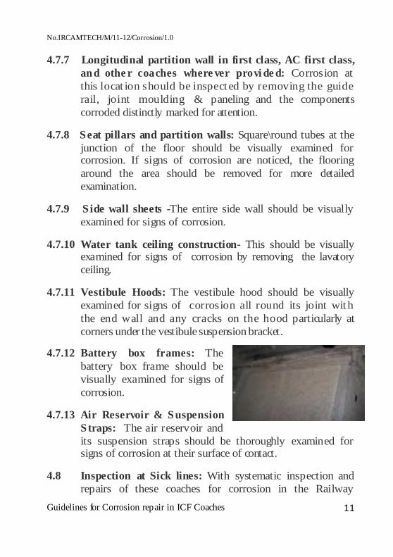
4.7.12 Battery box frames: The battery box frame should be visually examined for signs of corrosion.
4.7.13 Air Reservoir & Suspension S traps: The air reservoir and its suspension straps should be thoroughly examined for signs of corrosion at their surface of contact.
4.8 Inspection at Sick lines: With systematic inspection and repairs of these coaches for corrosion in the Railway

No.IRCAMTECH/M/11-12/Corrosion/1.0
Guidelines for Corrosion repair in ICF Coaches 12
workshops as detailed in this Handbook, it should be possible to ensure that coaches having extensive corrosion are not in service. When considered necessary, Railways may also organize inspection at primary coach maintenance depots to identify coach’s heavy corrosion for dispatch to Railway workshops.
5.0 CORROSION REPAIRS
5.1 Material & treatment of components
It is essential to use low allow high tensile corten type steel sheets and plates to IRS M41-97 for repairs of integral coaches. The thickness of steel sheet\plates to be used shall be as under:
SN. Description of components Thickness of steel sheets & plates IRS- M 41-97
1 Inner head stock Centre plate 12 mm Inner beam, Web plate 10 mm 2 Outer head stock 8 mm 3 Sole bar 5 mm
4 End wall stanchions cross bears above & below trough floor
4 mm
5 Turn under
With elongated holes Without elongated holes
4 mm 2 mm
6 Floor side moulding 2 mm
7 Through floor body side pillars body side and end wall panels waist rail and light rail
2 mm
8 Roof sheet 1.6 mm

No.IRCAMTECH/M/11-12/Corrosion/1.0
Guidelines for Corrosion repair in ICF Coaches 13
� Components of 5 mm or more thickness should be grit blasted and immediately followed by application of red oxide zinc chromate primer.
� Welding electrodes and paints should be of the prescribed quality conforming to the relevant is IS\IRS specification, particulars of which are given in Annexure- 3. Where the corrosion noticed is of a very minor nature and has just started to reach the bare metal and the surface treated with two coats of primer. In addition under frame members should be given four coats bituminous solution.
5.2 Procedure for corrosion repairs:
Wherever a portion of the sole bar is replaced during corrosion repair, the bottom portion of side wall pillars at this location should also be simultaneously replaced.
Corrosion repairs are required to be carried out to the best standard of workmanship. Trained and experienced welders should be deputed for carrying out welding under careful supervision of qualified welding supervisors. Suitable arrangement should be made for dry storage of electrodes. Approved class B-II electrodes suitable for vertical and overhead welding should only be used for corrosion repairs. Reference may be made in this connection to the approved brands of electrodes issued by RDSO. Procedure detailed in ‘Code of Practice for painting of all metal coaches’ should be followed for cleaning and painting of surfaces which are attended to during corrosion repairs. Effective supervision and inspection should be introduced at all important stages of corrosion repairs.

No.IRCAMTECH/M/11-12/Corrosion/1.0
Guidelines for Corrosion repair in ICF Coaches 14
I INSTRUCTIONS FOR STIFFENING OF SOLE BAR: (Ref: RDSO drawing No. CG-10086)
A. Middle doorways of 4 doors, aside shell:
� Support the coach body at the body bolsters.
� Remove the footboards.
� Remove the step sheets for the footboard and modify the same as shown as detail ‘Y’ in RDSO drawing No. SK-78101.
� Cutoff the side wall sheet to a height of 500 mm and to a length of 350 mm on outer side of both doorways and also cut complete side wall to a height of 500 mm in between the doorways.
� Cut off the door corner sheets and doorway pillars on either side of doorways and the remaining two pillars in between doorways to a height of 430 mm.
� Prepare the sole bar stiffener as shown in RDSO drawing No. CG-10086.
� Prepare door corner sheets and part pillars as shown at detail ‘X’ in RDSO drawing No. SK-78101.
� Weld part pillars and corner sheets to the existing pillars and corner sheets and to the sole bar stiffeners as shown at section ‘AA’. Weld sidewall sheet as

No.IRCAMTECH/M/11-12/Corrosion/1.0
Guidelines for Corrosion repair in ICF Coaches 15
explained in Annexure III.
� Replace the foot steps after modifying the top foot step as shown at section ‘BB’ of RDSO drawing No. SK-78101.
� Clean and paint. Parts/ sub-assembly which would become inaccessible after assembly/ welding should be properly cleaned and painted before assembling.
B. Luggage compartment doorways of SLR coaches to CSC 1405 /1692
� Support the coach body at the body bolsters.
� Remove the footboards and step sheets if not already done earlier.
� Cutoff the side wall sheet to a height of 500 mm and to a length of 600 mm on either side of doorways of luggage compartments.
� Cut off the door corner sheets and doorway pillars to a height of 430 mm.
� Prepare the sole bar stiffener and cover plate and weld as shown in the sketch.
� Prepare door corner sheets and doorway part pillars.
� Weld doorway part pillars and corner sheets to the existing pillars and corner sheets and to the sole bar stiffeners. Weld sidewall sheet as explained in III.
� Clean and paint Parts/ sub-assembly, which would become inaccessible after assembly/ welding should be properly cleaned and painted before assembling.
Note: Foot-Boards are not to be provided for the doorways of luggage compartment.

No.IRCAMTECH/M/11-12/Corrosion/1.0
Guidelines for Corrosion repair in ICF Coaches 16
C. Luggage compartment doorways of SLR coaches to CSC 1554. (Ref: RDSO drawing No. CG-10087)
� Support the coach body at the body bolsters.
� Remove the footboards and step sheets, if not already done earlier.
� Cutoff the side wall sheet to a height of 500 mm and to a length of 176 mm on lifting pad side and 800 mm on the other side (i.e. up to the next pillar) of doorways of luggage compartments.
� Cut off the door corner sheets and doorway pillars to a height of 430 mm.
� Prepare the sole bar stiffener, cover plate and closing pieces and welded.
� Prepare door corner sheets and doorway part pillars.
� Weld doorway part pillars and corner sheets to the existing pillars and corner sheets and to the sole bar stiffeners. Weld sidewall sheet as explained in III.
� Clean and paint Parts/ sub-assembly, which would become inaccessible after assembly/ welding should be properly cleaned and painted before assembling.
Note: Foot-Boards are not to be provided for the doorways of luggage compartment.

No.IRCAMTECH/M/11-12/Corrosion/1.0
Guidelines for Corrosion repair in ICF Coaches 17
II INSTRUCTION FOR CORROSION REPAIR OF SOLE BAR. (Ref: RDSO drawing No. CG-10101)
A. At locations other than the lifting pads and bolster:
� Support the coach body on bolster.
� Support the coach body near the sole bar portion under replacement through the window opening on wooden struts.
� Provide additional wooden supports on either side of the sole bar to be cut..
� Cut off the side wall sheets and turn under to a height of 500 mm covering length of approximately 200 mm on either side of the sole bar to be replaced.
� Cut off the trough floor, cross bearers and body side pillars at the locations where the sole bar portion is to be renewed. Ensure that cross bearers are not damaged.
� Cut off the sole bar and grind the edges and prepare for a 'V’ Butt joint.

No.IRCAMTECH/M/11-12/Corrosion/1.0
Guidelines for Corrosion repair in ICF Coaches 18
� Prepare a new sole bar piece of the requisite length with edges suitable for a ‘V’ Butt joint.
� Tack weld the new sole bar piece at both ends.
� Check and ensure straightness of the sole bar and overall alignment.
� Tack weld cross bearers, if any, to the new sole bar piece.
� Weld both ends of the sole bar.
� Weld cross bearers, support piece and trough floor.
� Weld new body pillar part, sidewall sheet and turn under as detailed in III. These components also require replacement whenever a part of sole bar is replaced for corrosion.
Note: -
i) If sole bar of length more than 2400 mm requires replacement, the same should be done in lengths not exceeding 2400 mm at each stage.
ii) If sole bars are to be replaced on both sides, the joints must be staggered and both ends should not be attended to simultaneously.
iii) If the sole bar at head stock location requires renewal,

No.IRCAMTECH/M/11-12/Corrosion/1.0
Guidelines for Corrosion repair in ICF Coaches 19
the sole bar to a distance of 300 mm towards body bolster from the inner head stock should also be replaced.
iv) If the coach under repair has its under frame and body pillars upto waist rail level pasted with FRP tissue, the portion of FRP tissue damaged during corrosion repair should be painted with RDSO specification M&C/PCN/123/2006 for high performance anticorrosion epoxy.
B. At Body Bolster and lifting pad locations: (Ref: RDSO drawing No. CG-10102)
� Support coach body on the body bolster, where sole bar is not to be attended to.
� Support coach body on wooden trestles on both the sides of the bolster where sole bar is to be replaced.
� Support the superstructure of the coach body through the window openings where the sole bar is to be cut.
� Cut off sidewall sheets with turn under to a height of 500 mm and side wall pillars to a height of 430 mm in the area where sole bar is under replacement.
� Tack weld temporary mild steel stays to the body bolster

No.IRCAMTECH/M/11-12/Corrosion/1.0
Guidelines for Corrosion repair in ICF Coaches 20
and sole bar, The location on the sole bar should be reasonably away from the point where, it is to be cut for replacement.
� Cut the cross bearers, if any, attached to the sole bar portion to be renewed.
� Cut off the trough floor to a distance of 180 mm from sole bar and to a length of 600 mm in the bolster area.
� Cut the sole bar to a distance of approximately 200 mm away from the point of replacement and prepare the edges for a 'V' butt weld joint. Care should be exercised not to damage the body bolster when cutting off the sole bar. Carefully grind the body bolster without damages.
� Tack weld a new piece of sole bar whose edges are similarly prepared for a ‘V’ butt weld.
� Weld packing piece (ICF Drg. No. T-1-1-505) to the sole bar as shown in Section ‘CC’ of 10102 .
� Weld the sole bar on either side after ensuring straightness and overall alignment.
� Weld body bolster to the new sole bar.
� In case of damage to the edges of the body bolster or if any part of the body bolster near the sole bar is to be replaced for corrosion, the following procedure may be adopted: -
a) Cut off the trough floor to a distance of 350 mm from the sole bar and to a length of 600 mm in the bolster area. Cut the top plate, bottom plate and webs of the booty bolster to the dimensions.

No.IRCAMTECH/M/11-12/Corrosion/1.0
Guidelines for Corrosion repair in ICF Coaches 21
b) Prepare a new sole bar of the required length. Weld the two web pieces (item 1) to the new sole bar piece.
c) Weld packing piece (ICF Drawing No. T-1-1-505) to the sole bar.
d) Tack weld the sole bar piece on both sides and check for straightness and overall alignment of the sole bar and body bolster web pieces.
e) Full weld the sole bar piece on either side.
f) Weld the body bolster web piece's (item 1) to the webs of the body bolster at an angle.
g) Weld the bottom flange of the body bolster (item 2) to the sole bar and the body bolster.
h) Weld the top flange piece (item 3) to the body bolster and sole bar.
i) Weld trough floor to the support piece.
� Weld new body pillars turn-under and sidewall as explained in -III
Notes-
i) If sole bars are to be replaced on both sides of the body bolster, the joints should be staggered, and both ends of the body bolster should not be, attended to simultaneously.
ii) Renewal of the sole bar near the body bolster should be taken at the last stage after renewing the sole bar, if need be at other locations.

No.IRCAMTECH/M/11-12/Corrosion/1.0
Guidelines for Corrosion repair in ICF Coaches 22
C. At lifting pad locations (Ref: RDSO drawing No. 10102)
� Follow instructions enumerated at A above for replacement of the sole bar portion.
� Before welding the turn-under and side wall sheet, weld the modified lifting pad as shown in Section ‘BB’ of Sketch No. 10103)

No.IRCAMTECH/M/11-12/Corrosion/1.0
Guidelines for Corrosion repair in ICF Coaches 23
III Instructions for Corrosion Repairs of Side Wall Sheets & Body Pillars & Turn under.
(Ref: RDSO drawing No. CG-10103 & CG 10089)
A. Renewal of sidewall sheets.
� Support coach body at body bolsters.
� Cut the sidewall sheet requiring replacement and grind the burnt edges.
� Prepare a new side wall sheet with 5 mm diameter holes at appropriate locations for plug welding, to the side wall pillars when required and tack weld the same on all the four sides.
� Check the sidewall for straightness and ensure overall alignment.

No.IRCAMTECH/M/11-12/Corrosion/1.0
Guidelines for Corrosion repair in ICF Coaches 24
� Weld the side wall sheets on all four sides and plug weld the same to body side pillars, if the inside paneling and flooring have not been removed for any other purpose in case the inside paneling and trough floor have been removed for some other purpose, side wall sheets may be welded with the body pillars from inside and plug welding avoided.
� Grind flush the welded joints on all the four sides to obtain a smooth exterior finish.
� In case if pillars are renewed, FRP tissue on a coach with sealed windows, the elongated holes and the thicker sheets for the turn under are not necessary and the side wall sheets should be directly welded to, the bottom of the sole bar.
B. Renewal of Body Pillars: (Ref: RDSO drawing No. CG-10103)
� Support the coach body on the body bolsters.
� Remove the inside panels, flooring and floor side mouldings to gain access to the body pillars.
� Cut off the turn under and side wall sheet up to sufficient height so as to fully expose the corroded body

No.IRCAMTECH/M/11-12/Corrosion/1.0
Guidelines for Corrosion repair in ICF Coaches 25
pillars.
� Cut off alternate body pillars on the same side to a height of approximately 430 mm or 525 mm or 600 mm as the need may be, as shown in the sketch exercising care to ensure that the sole bar is not damaged. Prepare the edge of pillar for ’V’ butt-welding.
� Clean the surface of the sole bar thoroughly of rust etc.
� Tack welds the new body pillar part to the pillar and sole bar.
� Check and ensure straightness and alignment of the body pillars.
� Full weld the body pillar part to the pillar and sole bar.
� Cut off the remaining body pillars and attend to them in like manner as indicated above.
� Replace the body sidewall sheet as indicated in Para A above.
� Clean and paint the inner surface of the replaced sidewall and body pillars.
� Replace floor side moulding and relay flooring.
� Replace inside panel.
C. Renewal of Turn Unders: (Ref: RDSO drawing No. CG 10099)
� Support coach body on the bolsters.
� Cut off side wall sheet also to a height of 500 mm to the required length.
� Clean the surface of the sole bar thoroughly of rust
No.IRCAMTECH/M/11-12/Corrosion/1.0
Guidelines for Corrosion repair in ICF Coaches 26
etc. to the bare metal and ensure there is no corrosion on the sole bar.
� Prepare a new turn-under (see note No. 2 below) to the length required with edge prepared for a ‘V’ Butt joint and tack weld the same to the body pillars and bottom of the sole bar.
� Check the turn under or straightness.
� Weld intermittently the body pillars to the turn under.
� Replace the sidewall sheets as given in Para A above.
Note:
1. Whenever longer length of side wall sheet or turn under is replaced the ski should be properly tensioned by spot heating before giving anti-corros ive treatment.
2. The new turn under part should be compatible with the existing turn under on the coach viz.: -
3. For a coach with 5 mm thick turn under with elongated holes, the new part should also be of 5 mm thickness with elongated holes as shown in RDSO drawing No. CG - 10099
4. For a coach with 2 mm thick turn under, the new part should be of 2 mm thickness without holes and all other dimensions as per RDSO drawing No-CG-10099)
No.IRCAMTECH/M/11-12/Corrosion/1.0
Guidelines for Corrosion repair in ICF Coaches 27
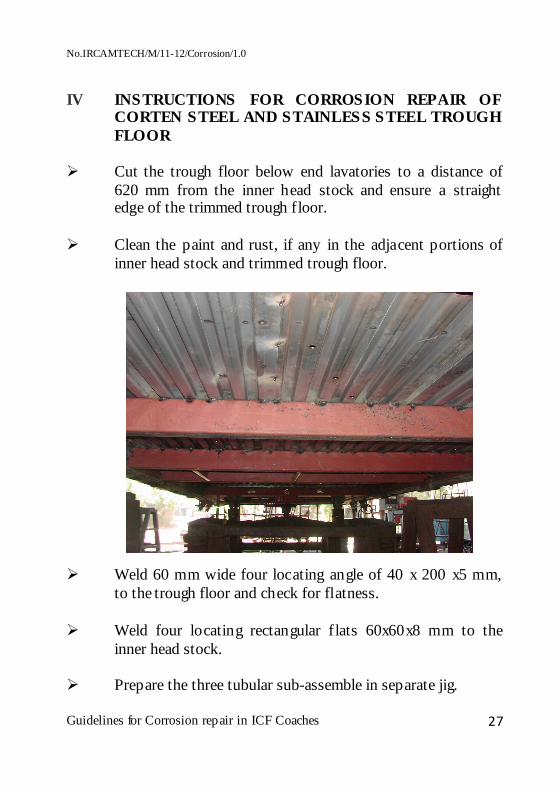
IV INSTRUCTIONS FOR CORROSION REPAIR OF CORTEN STEEL AND STAINLESS STEEL TROUGH FLOOR
� Cut the trough floor below end lavatories to a distance of
620 mm from the inner head stock and ensure a straight edge of the trimmed trough floor.
� Clean the paint and rust, if any in the adjacent portions of
inner head stock and trimmed trough floor.
� Weld 60 mm wide four locating angle of 40 x 200 x5 mm, to the trough floor and check for flatness.
� Weld four locating rectangular f lats 60x60x8 mm to the
inner head stock.
� Prepare the three tubular sub-assemble in separate jig.

No.IRCAMTECH/M/11-12/Corrosion/1.0
Guidelines for Corrosion repair in ICF Coaches 28
� Tack weld tubular assemblies to the trough floor and inner head stock.
� Ensure proper alignment of the tubular frame assembly with
that of the trough floor and overall straightness.
� Full weld the tubular frame assembly to the inner head stock and trough floor.
� Weld the cross bearer channel 60/30 x 119 x 5mm at the
location shown in the sketch.
� Weld connecting pieces 110x75 mm between the tubes and the new cross bearers.
� Clean and paint tubular frame assembly. � Note: Doorways should be stiffened as in annexure-I and

No.IRCAMTECH/M/11-12/Corrosion/1.0
Guidelines for Corrosion repair in ICF Coaches 29
RDSO drawing No. CG-10086 before the tubular sub- assemblies is welded.
Guard's lavatories � Guard's and middle lavatories of SLR coaches (Ref: RDSO
drawing No. CG-10107).
� Cut off trough floor below Guard's lavatories to a distance of 916mm from the body bolster towards head stock along with cross bearers.
� Clean paint and rust, if any, in the adjacent parts of the
bolster and trough floor.
� Weld four locating angles 40x200x5mm (width 60mm) as shown in the sketch on either side of the edges of the trough floor and check for straightness .and flatness.
� Prepare the new tubular sub-assemblies to the under frame.
� Tack weld the tubular assemblies to the under frame.
� Check and ensure alignment of the tubular frame with that
of the adjoining trough floor and overall straightness.
� Full weld the tubular frame to trough floor.
� Weld the cross bearer 60/30x119x5mm at the location.
� Weld connecting pieces 11Ox75x5 mm between tubular frame and the new cross bearer.
� Clean and paint the tubular frame assembly.

No.IRCAMTECH/M/11-12/Corrosion/1.0
Guidelines for Corrosion repair in ICF Coaches 30
Trough floor at other locations � Cut off the corroded Corten and Stainless Steel trough floor
to the length and width required. � Weld isolating plate of 5mm thick transversely after
grinding the edge of the trough floor straight. � Prepare a new Stainless Steel 301 trough floor members to
the dimensions required and tack weld the same to the isolating plates on either side.
� Ensure proper alignment of the replaced part with that of
adjoining parts. � Full weld trough floor to the isolating plates both at top and
bottom. � Weld intermittently the trough floor longitudinally to the
supporting piece and adjoining trough floor. Ensure the alignment in the longitudinal direction by suitably cutting off the trough floor to match with the new patch of Stainless Steel 301 trough floor.
� Drill 19 mm diameter holes in the valleys between two
isolating plates. � Clean and paint the affected area of trough floor. Note: In the case of coaches rifted with Corten Steel, Stainless Steel and combination of Corten Steel and Stainless Steel trough floor. the electrodes as specified in shall be used. Trough floor below luggage compartment of SLRs, LRs, etc.

No.IRCAMTECH/M/11-12/Corrosion/1.0
Guidelines for Corrosion repair in ICF Coaches 31
and bays adjacent to lavatories under doorways: � Attend to corroded floor as above.
� Provide 40x5mm thick isolating plates between the trough
floors below the luggage compartment and the adjacent passenger compartments or the bay adjacent to lavatory below doorway and the next bay .as the case may be and affected portion should be painted with high performance anticorrosion epoxy to RDSO Specification No. M&C/PCN/123/2006, over the trough floor, adjoining areas of sole bar. and side wall and body pillars up to waist rail level and cross bearers.
Note: 1. If during corrosion repairs whole length of the trough floor
needs replacement in that event the trough floor. sole bars, side wall and body pillars up to waist rail level and cross bearers should be painted with high performance anticorrosion epoxy to RDSO Specification M&C/PCN/12312006 .
2. During corrosion repair of coaches fitted with IRS M-41 trough floor, the corroded patches of IRS M-41 trough floor shall be replaced with Austenitic stainless steel (Grade 301), 1.7 mm thick, corrugated sections where these are necessary for replacement.

No.IRCAMTECH/M/11-12/Corrosion/1.0
Guidelines for Corrosion repair in ICF Coaches 32
V INSTRUCTIONS FOR REPLACEMENT OF OUTER HEAD STOCK DURING CORROSION REPAIRS
� Dismantle the buffers and check the buffer base periphery for corrosion and the bolt holes for securing buffers for wear and oblongivity /cracks.
� If the depth of
corrosion below the buffer base is insignificant, the bolt holes are not worn out and no cracks have developed, dean the rust and paint.
� Replace the buffer base.
� If corrosion is not significant and bolt holes for securing of
buffers are worn out / have become oblong, the holes should be filed up by welding and re-drill if required.
� If the corrosion is significant (i.e. loss in section is more
than 20% of original thickness) replace the buffer base.
� Remove the floor molding, end wall panel, lavatory, stainless steel inlay flooring/compreg PVC flooring up to a distance of 3OOmm in lavatory gang way and supporting member of compreg flooring in the gangway.
� Support the anti-telescopic stanchions at the bottom and sole
bar on suitable wooden stands.

No.IRCAMTECH/M/11-12/Corrosion/1.0
Guidelines for Corrosion repair in ICF Coaches 33
� Gas cut the head stock beam along with the vestibule sill
and other corroded components and the end wall sheet, ensuring that no damage is caused to the anti-telescopic stanchions, sole bar and the stiffener tube behind the buffers.
� Grind sole bar flanges, stiffener tubes behind buffer (center
stiffener) and floor stiffener stanchions to match with the head stock.
� Remove all existing paint of visible area by steel wire brush
to bare metal & prepare the visible surface for painting.
� Prepare a new head stock beam arrangement complete with 8 mm steel plate to drawing No ICF/STD-1-2..002. Before welding ensure correctness of the bolt hole size for buffer bolts in headstock beam as well as stiffeners (Item 5,15. 6,16) are welded in the head stock in position.
� Check for straightness of head stock and over all alignment.

No.IRCAMTECH/M/11-12/Corrosion/1.0
Guidelines for Corrosion repair in ICF Coaches 34
� Full weld the new head stock to the sole bar, stiffener tubes, anti telescopic stanchions, floor stiffeners and guide angles. Weld a new vestibule sill over the headstock.
� Welding shall be done by "D' class electrodes to IRS - M 28 (latest Rev.) or class IV MIGIMAG welding wires as per specification IRS-M46 (latest Rev.)
� While welding with D class electrodes following special
care should be taken as - these are basic coated electrodes:
a) The electrode must be preheated to about 250°C for two hours or as recommended by electrode manufactures before use.
b) While welding with AC. the welding transformer must have minimum OCV 80 volts for its smooth running.
c) If welding with DC equipment, the electrode must be
connected with positive terminal of equipment d) During positional welding, 4 mm or less diameter
electrodes to be preferred for better control of bead.

No.IRCAMTECH/M/11-12/Corrosion/1.0
Guidelines for Corrosion repair in ICF Coaches 35
� Welding shall be preferred in f lat position. Vertical up welding shall be used in place of vertical down.
� Welded head stock should cleaned again by steel wire brush. � Paint the head stock and all visible members by high
performance anticorrosion epoxy coating RDSO specification No M & C/ PCN/123/2006.
� Weld a new end wall sheet as required. � Clean and paint the end wall.
No.IRCAMTECH/M/11-12/Corrosion/1.0
Guidelines for Corrosion repair in ICF Coaches 36
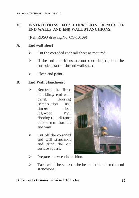
VI INSTRUCTIONS FOR CORROSION REPAIR OF END WALLS AND END WALL STANCHIONS.
(Ref: RDSO drawing No. CG-10109)
A. End wall sheet
� Cut the corroded end wall sheet as required.
� If the end stanchions are not corroded, replace the corroded part of the end wall sheet.
� Clean and paint.
B. End Wall Stanchions:
� Remove the floor moulding, end wall panel, flooring composition and timber floor /plywood PVC flooring to a distance of 300 mm from the end wall.
� Cut off the corroded end wall stanchions and grind the cut surface square.
� Prepare a new end stanchion.
� Tack weld the same to the head stock and to the end stanchions.

No.IRCAMTECH/M/11-12/Corrosion/1.0
Guidelines for Corrosion repair in ICF Coaches 37
� Ensure proper alignment.
� Full weld the end stanchions.
Note: - i) If the head stock is also corroded and requires replacement, the same should be attended to first as described in "V” before replacement of the corroded end stanchions.
ii) ICF have been turning out coaches with end stanchions formed out of 4 mm thick sheet to IRS-M-41 instead of 5 mm plate. The replacement of end stanchions should, therefore, be with 4mm or 5 mm thickness according to the stanchion removed.
� Clean and paint.
� Replace the end wall panels and floor moulding.

No.IRCAMTECH/M/11-12/Corrosion/1.0
Guidelines for Corrosion repair in ICF Coaches 38
VII INSTRUCTIONS FOR CORROSION REPAIR OF TRA VENTILATORS . ( Ref: RDSO drawing No. CG-10110)
TRA Type Ventilators:
� Remove the air-duct casing below the roof ventilators and insulating material.
� If no corrosion is noticed on the roof sheet, cutoff the corroded ring and the corroded channel supports and replace them with new ring and channel supports.
� If corrosion is noticed in the roof sheet, cut off the roof sheet around the ventilator to a distance of 345x345 mm and grind the edges straight.
� Provide a backing strip 25 mm in width all around.
� If corrosion is noticed on the roof sheet around any of the supporting channels cut off the roof sheet around that channel to a distance of 95 x 45 mm and grind the edges. Prepare a new roof sheet piece of 100 x 50 mm along with supporting channel and weld in position.
� Repair a new roof sheet of size 345x345 mm with ring complete & weld the same in position.

No.IRCAMTECH/M/11-12/Corrosion/1.0
Guidelines for Corrosion repair in ICF Coaches 39
VIII INSTRUCTIONS FOR CORROSION REPAIRS OF BODY SIDE DOORS.
(Ref: RDSO drawing No. CG-10083)
� Remove the body side door and place the same on a suitable stand,
� Set louver and glass shutters in raised position.
� Remove the-inside bottom panel.
� Check for corrosion of outer panels etc.
� If corrosion is light, scrape of rust to bare metal.
� Clean and paints
� If corrosion is heavy, gas cut the corroded parts and grind the edges straight.
� Butt weld the outer panel to the existing panel along with the stiffeners.
� Clean and paint.
� If the curved portion of the outer panel and pillar are corroded, the corroded portions should be cut and replaced by Butt-welding patch plates and then weld ground smooth outside.

No.IRCAMTECH/M/11-12/Corrosion/1.0
Guidelines for Corrosion repair in ICF Coaches 40
Note: Body side doors of coaches manufactured since 1966 have been modified by providing an open bottom to avoid incidence of corrosion. Body side doors of coaches built earlier have bottom stiffener. This bottom stiffener should be removed whenever attention is required for the body side doors and modifications.

No.IRCAMTECH/M/11-12/Corrosion/1.0
Guidelines for Corrosion repair in ICF Coaches 41
IX INSTRUCTIONS FOR CORROSION REPAIRS OF SEAT PILLARS IN COACHES WITH PVC FLOORING
� If the corrosion at the bottom of the seat pillars is light, scrap off the rust to bare metal, clean well and re-paint.
� If the corrosion is heavy remove the PVC sheets at the location of corroded pillar as such an extent that underneath compreg board is exposed completely up to support points (Refer ICF SK-4-1-135).
� Remove the fixing screws of compreg board and lift it from its position.
� Cut off the corroded pillar to a height of 150mm from the bottom of the supporting channel.
� Prepare a new pillar as shown in section 'AA' and to a height of 150mm with a base to ICF drg. No. T -1-0-625 and weld

No.IRCAMTECH/M/11-12/Corrosion/1.0
Guidelines for Corrosion repair in ICF Coaches 42
the new pillar to the supporting channel and pillar. Clean and paint.
� Prepare a cover for seat pillar to ICF I SK -4-1-131 for single seat sleeve frame to item 31 of ICF I SK - 4- 1- 135.
� Follow the procedure for repairing PVC flooring of ICF built coaches to C-8701 for relaying the flooring.
Partition walls in coaches with PVC/Compreg floorings
� Remove the PVC skirting and panel on both sides.
� If corrosion is light, scrap off rust to bare metal, clean and repaint, replace paneling and PVC skirting.
� If corrosion is heavy, remove the PVC sheets to such an extent that underneath compreg board is exposed completely up to support points (Ref: ICF SK - 4 -1-135).
� Remove the fixing screws of compreg board and lift it from its position.
� Cut off the corroded pillar to a height of 160mm from the bottom and grind the edges of the pillar square.
� Prepare a new pillar and weld the same to the supporting channel and pillar.
� Prepare a supporting plate and weld the same to supporting channel and pillar.
� Clean and paint.

No.IRCAMTECH/M/11-12/Corrosion/1.0
Guidelines for Corrosion repair in ICF Coaches 43
X PROCEDURE OF CHANGING OF DEFECTIVE BODY BOLSTER
� The reject able defects of Body bolster are:
• Thin edge of bottom Plate due to wear and tear (Thickness reduces from 16mm to 12.8mm).
• Corrosion taken place (Corroded Body Bolster). • Bent of bottom Plate due to hitting of bogie Sole bar. • Crack develops in Body Bolster.
� After Completion of ir1spection, if body bolster found defective required to be replaced then sequence of operation for changing the body bolster are as under:
• Lift the coach and place it on trestles. • Weld suitable supports with rail, in both ends in the

No.IRCAMTECH/M/11-12/Corrosion/1.0
Guidelines for Corrosion repair in ICF Coaches 44
following locations: • Both side of inner and outer Head Stock • One side of sole bar in. the location where the bolster
is to be change. • All Supports is to be welded in such a way that while
removing old bolster and putting hew one the geometry of the coach should not be disturbed. Measure the distance from the head stock to the centre of the body bolster which is to be removed and record it.
� Cut and remove the trough floor above the bolster to be
change. � Cut one side of sole bar not less then four feet of the bolster
location and provide suitable weld support to both ends of the sole bar.
� Cut the bolster from other side. � Remove the bolster. � Weld a suitable support matching the bottom flange of the
sole bar where it was cut. � Put the new bolster into the coach as per the dimension
recorded earlier and also ensure the end bottom of the bolster should be properly seated with sole bar bottom flange.
� Check dimension and ensure it.

No.IRCAMTECH/M/11-12/Corrosion/1.0
Guidelines for Corrosion repair in ICF Coaches 45
� Fit the sole bar that was cut. � Full weld the bolster with both side of the sole bar. Fit
trough floor above the bolster. � After full welding, lower the coach on Bogie.

No.IRCAMTECH/M/11-12/Corrosion/1.0
Guidelines for Corrosion repair in ICF Coaches 46
XI SPECIFICATION FOR MATERIALS USED IN CORROSION REPAIRS OF SHELL.
S. N Item Specification No. 1 Steel sheets for manufacture of
1.1 Trough floor 2mm for IRSM-41 Gr. I,1.7 mm for Austenitic stainless steel.
1.2 Pillars, sidewall sheet, light rail, waist rail and end wall sheet.
2 mm for IRSM-41 Gr. I
1.3 Car line 2 mm for IRSM-41 Gr. I 1.4 Roof sheet and longitudinal
st iffener 1.6 mm for IRSM-41 Gr. I
1.5 Cant rail and Ribs 3.15 mm for IRSM-41 Gr. I 1.6 Other structural members IRS:M-41 Gr. I 2 Steel plates for manufacture of
2.1 Sole bars and turn under 5 mm for IRSM-41 Gr. I 2.2 Cross bearers above and below
trough floor, end wall stanchions 4 mm for IRSM-41 Gr. I
2.3 Outer headstock beam 8 mm for IRSM-41 Gr. I 2.4 Other structural members like sole
bar stiffeners IRSM-41 Gr. I
3 Tubes for tubular frame below lavatory
IS: 1239 Pt. 1, Tab. 3
4. Non-Structural members 4.1 Sheets like skirt ing plate for
reservoirs and floor side moulding IRSM-41 Gr.
4.2 Plates IRSM-41 Gr.1 5 Paint RDSO Specification No.
M&C/PCN/123/2006 for high performance anticorrosion epoxy coating.

No.IRCAMTECH/M/11-12/Corrosion/1.0
Guidelines for Corrosion repair in ICF Coaches 47
XII INSTRUCTION FOR WELDING OF D CLASS ELECTRODES. WELDER QUALITY & OTHERS
� While welding with D class electrodes following special care should be taken as these are basic coated electrodes.
• The electrode must be preheated to about 250°C for two hours or as recommended by electrode manufactures before use.
• While welding with AC, the welding transformer must have minimum OCV-80 volts for its smooth running.
• If welding with DC equipment, the electrode must be connected with positive terminal of equipment.
• During positional welding, 4 mm or less diameter electrodes to be preferred for better control of bead.
� Welding shall be preferred in flat positi()n; vertical up welding shall be used in place of vertical down.
� For the periodical checking of competency of welder the Railway should follow IS: 7310 (Part-1). This specification covers the approval test for welder working to approved welding procedure. This is BIS standard also stipulates the norms for approval of welder. Welder approval test record may be kept as per appendix-A of this IS specification.
� RDSO specification No M&CIPCN/12312006 for high performance anticorrosion epoxy coating to be adopted in all under frame member where Bituminous solution and Emulsion where painted earlier.
� Stainless steel cutting shall be done with arc cutting by two methods:
No.IRCAMTECH/M/11-12/Corrosion/1.0
Guidelines for Corrosion repair in ICF Coaches 48
i) By using class N1 electrodes as per IRS M-28-Rev.2.
ii) Portable plastna arc cutting machine (The equipment consistent of power source, a control unit, and one or more gases to function as orifice and shielding gas and cutting torch).

No.IRCAMTECH/M/11-12/Corrosion/1.0
Guidelines for Corrosion repair in ICF Coaches 49
6.0 CORROSION REPAIR PROCEDURE OF HEAD STOCK AND THEIR ASSEMBLY
During last two years, there has been an increase in the
cases of en-route detachment of coaches due to major weld failures. These failures have occurred due to working out of head stock, draw bar assembly and sole bar cracks etc. The quality of corrosion repair has a direct bearing on the safe running of coaches. RDSO had been advised to prescribe complete procedure for corrosion repair of head stock and other critical areas.
RDSO has carried out sample check of welding practices and type of electrodes being used for welding of critical areas. It is noted that railways are either not using "'D" class electrodes for welding of IRS M-41 or face difficulty in its usage. Railways are advised to take following care during welding with "D” class electrodes i.e.
a.) The electrode must be preheated to about 250°C for two hours or as recommended by electrode manufacturers before use.
b.) While welding with AC, the welding transformer must have minimum OCV -80 volts for its smooth running.
c.) If welding with DC equipment, the electrode must be connected with positive terminal of equipment.
d.) During positional welding. 4 mm or less diameter electrodes to be preferred for the corrosion repair procedure of head stock, their assembly and precautions to be taken during welding and painting after repair in ICF/RCF coaches are contained in following annexure:
No.IRCAMTECH/M/11-12/Corrosion/1.0
Guidelines for Corrosion repair in ICF Coaches 50
1. Instructions for replacement of Outer Head Stock during Corrosion Repairs: Annexure -1
2. Instructions for replacement of Headstock Assembly during Corrosion Repairs: Annexure -2
3. Welding Electrode &. Welding Wire for different combination of steel material Annexure -3
Railways are advised to follow the above procedure during corrosion repair in critical areas like head stock, draw gear, etc. (RDSO Letter No. MC/CRN/REH dated 21.12.2010)

No.IRCAMTECH/M/11-12/Corrosion/1.0
Guidelines for Corrosion repair in ICF Coaches 51
Annexure -1
INSTRUCTIONS FOR REPLACEMENT OF OUTER HEAD STOCK DURING CORROSION REPAIRS
� Dismantle the buffers and check the buffer base periphery for corrosion and the bolt holes for securing buffers for wear and oblongivity /cracks.
� If the depth of corrosion below the buffer base is
insignificant, the bolt holes are not worn out and no cracks have developed, dean the rust and paint.
� Replace the buffer base.
� If corrosion is not significant and bolt holes for securing of
buffers are worn out / have become oblong, the holes should be filed up by welding and re-drill if required.
� If the corrosion is significant (i.e. loss in section is more
than 20% of original thickness) replace the buffer base.
� Remove the floor molding, end wall panel, lavatory, stainless steel inlay flooring/compreg PVC flooring up to a distance of 3OOmm in lavatory gang way and supporting member of compreg flooring in the gangway.
� Support the anti-telescopic stanchions at the bottom and sole
bar on suitable wooden stands.
� Gas cut the head stock beam along with the vestibule sill and other corroded components and the end wall sheet, ensuring that no damage is caused to the anti-telescopic stanchions, sole bar and the stiffener tube behind the buffers.

No.IRCAMTECH/M/11-12/Corrosion/1.0
Guidelines for Corrosion repair in ICF Coaches 52
� Grind sole bar flanges, stiffener tubes behind buffer (center stiffener) and floor stiffener stanchions to match with the head stock.
� Remove all existing paint of visible area by steel wire brush
to bare metal & prepare the visible surface for painting.
� Prepare a new head stock beam arrangement complete with 8 mm steel plate to drawing No ICF/STD-1-2..002. Before welding ensure correctness of the bolt hole size for buffer bolts in headstock beam as well as stiffeners (Item 5,15. 6,16) are welded in the head stock in position.
� Check for straightness of head stock and over all alignment.
� Full weld the new head stock to the sole bar, stiffener tubes,
anti telescopic stanchions, floor stiffeners and guide angles. Weld a new vestibule sill over the headstock..
� Welding shall be done by "D' class electrodes to IRS - M 28
(latest Rev.) or class IV MIGIMAG welding wires as per specification IRS-M46 (latest Rev.)
� While welding with D class electrodes following special
care should be taken as - these are basic coated electrodes:
a) The electrode must be preheated to about 250°C for two hours or as recommended by electrode manufactures before use.
b) While welding with AC. the welding transformer must
have minimum OCV 80 volts for its smooth running. c) If welding with DC equipment, the electrode must be
connected with positive terminal of equipment

No.IRCAMTECH/M/11-12/Corrosion/1.0
Guidelines for Corrosion repair in ICF Coaches 53
d) During positional welding, 4 mm or less diameter electrodes to be preferred for better control of bead.
� Welding shall be preferred in f lat position. Vertical up
welding shall be used in place of vertical down. � Welded head stock should cleaned again by steel wire brush. � Paint the head stock and all visible members by high
performance anticorrosion epoxy coating RDSO specification No M & C/ PCN/123/2006.
� Weld a new end wall sheet as required. � Clean and paint the end wall.

No.IRCAMTECH/M/11-12/Corrosion/1.0
Guidelines for Corrosion repair in ICF Coaches 54
Annexure -2 INSTRUCTIONS FOR REPLACEMENT OF HEAD STOCK ASSEMBLY DURING CORROSION REPAIRS (A) Cutting of Headstock Assembly: � Dismantle the buffers, remove the floor moulding, end wall
panel, stainless steel inlay flooring from lavatory / compreg PVC flooring up to door way and supporting member of compreg /PVC flooring.
� If the corrosion is significant i.e. loss in thickness of section
is more than 20% of original thickness at any location on inner head stock and their other members, the assembly should be replaced.
� Gas cut the vestibule sill and the end wall sheet up to
required height. � Provide Bolster Support with Bogie Frame and Bottom
Portion of Sole bar flange to rail line. � Measure the Camber of the coach by "Piano Wire System",
and also measure the height of the bottom flange of the head stock from the rail level.
� Note Down the camber and height of head stock from rail
level. � Cut the end panel by gas cutting up to required height. � Remove the Yoke and cut the end stanchion pillar by gas
cutting.

No.IRCAMTECH/M/11-12/Corrosion/1.0
Guidelines for Corrosion repair in ICF Coaches 55
� Cut the sole bar near door pillar, sole bar boxing and body
side pillar at both side. � Cut the Lavatory tube/trough floor, welded with inner head
stock by gas cutter. .
(B) Fabrication of headstock assembly: Fabricate the complete head stock with 8 mm outer beam (outer head stock) to RCF Drawing No CC12230 or ICF drawing No. ICF/STD-1-2-001 on a welding manipulator for facilitating down hand full welding or procure from trade. (C) Fitting of headstock assembly � From the welding manipulator place the head stock
assembly by EOT crane (if manufactured in house) on the lifting platform.
� Move the loaded lifting platform for fitment to place where
old one was removed by gas cutting.
� Fully weld the supports on the both side of the bottom flange of old sole bar to the inner head stock.
� Finish cut the outside end stanchion pillar as per the
required height.
� Place the lifting platform in proper place and lift it up to the required height. Push it forward so that the inner head stock is support welded with the old sole bar.
� Tack weld two end stanchion at bot/1 end with the old one

No.IRCAMTECH/M/11-12/Corrosion/1.0
Guidelines for Corrosion repair in ICF Coaches 56
and weld two angles at bottom portion of it to provide support to the head stock portion of the assembly. .
� Place the assembly properly and set it as per dimensions by
measuring tape & plumb.
� Check the height of the lower flange bf Head Stock from rail level and adjust with the initial reading.
� Check all the dimensions and tack weld the head stock
assembly with the stanchion pillars, sale bar and sale bar boxing. Remove the welded support from the end stanchions.
� Tack weld the middle stanchion pillars.
� Now release the lifting trolley and pull it out.
� Weld two nos of vertical support with the lower portion of
the head stock on both ends, to provide support of the front portion of head stock assembly from rail line.
� Tack weld the head stock bottom strengthening plate at
proper place and carry out full weld.
� Fully weld the outside stanchion pillar with the head stock.
� While welding with 'D' class electrodes following special care should be taken as these are basic coated electrodes: a.) The electrodes must be preheated to about 250°C for
two hours or as recommended by electrode manufactures before use.
No.IRCAMTECH/M/11-12/Corrosion/1.0
Guidelines for Corrosion repair in ICF Coaches 57
b.) While welding with AC, the welding transformer must have minimum OCV-80 volts for its smooth running.
c.) If welding with DC equipment, the electrode must be
connected with positive terminal of equipment. d.) During positional welding, 4 mm or less diameter
electrodes to be preferred for better control of bead. � Welding shall be preferred in f lat position; vertical up
welding shall be used in place of vertical down.
� The vertical support of the head stock assembly should be removed after completion of the fitment of sale bars on both sides.
� Welded head stock should cleaned again by steel wire
brush.
� Paint the head stock and all visible members by high performance anticorrosive epoxy coating to RDSO specification M & C /PCN/123/2006.
� Measure the final camber of the coach at the ends, if
required re-adjusts it accordingly.
� Welding shall be done by 'D' class electrodes to IRS - M 28 (latest Rev.) or class IV MIG/MAG welding wires as per specification IRS-M46 (latest Rev.).

No.IRCAMTECH/M/11-12/Corrosion/1.0
Guidelines for Corrosion repair in ICF Coaches 58
Annexure -3
WELDING ELECTRODE & WELDING WIRE FOR DIFFERENT COMBINATION OF STEEL MATERIAL A) ICF Shell
Following types of steel are used for manufacture of major shell assemblies'
SN Major assemble Steels used 1. Side wall. End wall
and Roof structure IRS M-41 (Corten Steel)
2. Roof sheet and Trough floor
IRS M-41 (Corten Steel) Austenitic Steel (SS 301) (for 1. 7mm T rough floor)
3. Under frame IRS M-41 (Corten Steel) IS: 2062 E-250 & IS:1239 Pt.1 Tab.3
B) LHB Shell
Following types of steel are used for manufacture of major shell assemblies:
SN Major assemble Steels used
1. Side wall, End wall and Roof structure
Ferritic Steel (SS 409M)
2. Roof sheet and Trough floor
Austenitic Steel (SS 304)
3. Under frame IRS M-41/ Corten Steel & IS: 2062 E-250

No.IRCAMTECH/M/11-12/Corrosion/1.0
Guidelines for Corrosion repair in ICF Coaches 59
C) Electrode & Welding Wire Welding electrode and MIG/MAG welding wire for welding of different types of steels are:
SN Description
M MAW Electrode As per
IRS) M-28 2002
(Amendment-2)
MIG/MAG welding wire As per IRS M-46-2003 (Amendment -1 )
1 IRSM-41 with IRSM-41
'D’ class Class IV
2 AISI 304 with AISI 304
M1 Class Class VI
3 IRSM-41with AISI 301
M4 Class Class VII
4 AISI 304 with AISI 301
M1 Class Class VI
5 AISI 409 M with AISI 409 M
M2 Class Class VI
6 AISI 01/AISI3O4 with IS:2062 E-250
M4 Class Class VII
7 IS: 2062 E-250 to IS:2062 E-250 or IS:1239 Pt.1 Tab.3
A3/B1Class Cass I
8 IRSM-41 with IS: 2062 E-250
'D' Class ,
Class IV

If you have any suggestions and any specific comments, please write to us. Contact person : Executive Director Postal address : Indian Railways, Centre for Advanced Maintenance Technology, Maharajpur, Gwalior. Pin code - 474 005 Phone : 0751- 2470803 Fax : 0751- 2470841 Email address : [email protected]
To upgrade maintenance technologies and methodologies and achieve improvement in productivity and performance of all Railway assets and man power which inter-alia would cover reliability, availability, utilisation and efficiency.
OUR OBJECTIVE