MINISTACK Fuse Switch Disconnector Units product attachments/Isolators and...MINISTACK Fuse Switch...
24
MINISTACK Fuse Switch Disconnector Units
Transcript of MINISTACK Fuse Switch Disconnector Units product attachments/Isolators and...MINISTACK Fuse Switch...
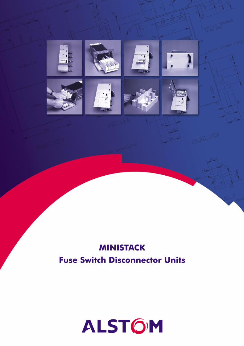
MINISTACKFuse Switch Disconnector Units

2
Introduction 3
Range 3
Ordering details 5-6
Dimensions 7-21
Operation and Maintenance Procedure 22
Technical and Performance Data 23
Contents
3
CMS
ALSTOM Industrial Products Divisionis continually developing the Ministackrange of switches to provide for therequirements of consulting engineers,contractors and switchboard builders.
The latest range of Ministacks include:
■ Uprated busbar (910A) for 100A& 200A stacks, 2 to 10 high.
■ New style sandwiched coppercable connectors fitted to the rearmoulding of 100A & 200A units.
■ 3&4 high 400A & 630A Ministacks.
■ NEW comprehensive range ofmixed stacks.
The Ministack now offers industry aclear choice in low voltage switchboarddesign. This design suits Form 1 toForm 4 types of separation. With theaddition of optional terminal shroudsplus the necessary barriers providedby the switchboard builder, Form 4separation is achievable.
Fuse switch disconnector units areavailable which have been successfullytested, and meet the requirements ofthe standard test as indicated byClause EE3 in Appendix EE of AS3439.1or special test as specified in ClauseEE6 of Appendix EE.
Ministacks
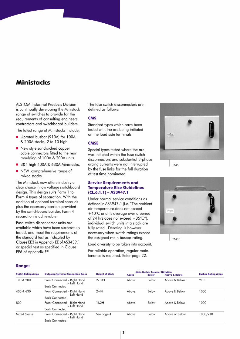
The fuse switch disconnectors aredefined as follows:
CMS
Standard types which have beentested with the arc being initiatedon the load side terminals.
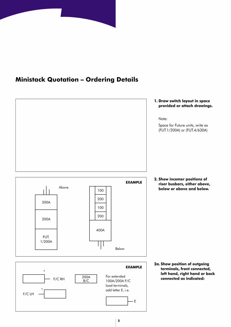
CMSE
Special types tested where the arcwas initiated within the fuse switchdisconnectors and substantial 3-phasearcing currents were not interruptedby the fuse links for the full durationof test time nominated.
Service Requirements andTemperature Rise Guidelines(CL.6.1.1) – AS3947.1
Under normal service conditions asdefined in AS3947-1 (i.e. “The ambientair temperature does not exceed+40°C and its average over a periodof 24 hrs does not exceed +35°C”),individual switch units in a stack arefully rated. Derating is howevernecessary when switch ratings exceedthe assigned main busbar rating.
Load diversity to be taken into account.
For reliable operation, regular main-tenance is required. Refer page 22.
CMSE
Range: Main Busbar Incomer Direction
Switch Rating Amps Outgoing Terminal Connection Types Height of Stack Above Below Above & Below Busbar Rating Amps
100 & 200 Front Connected – Right Hand 2-10H Above Below Above & Below 910Front Connected – Left HandBack Connected
400 & 630 Front Connected – Right Hand 2-4H Above Below Above & Below 1000Front Connected – Left HandBack Connected
800 Front Connected – Right Hand 1&2H Above Below Above & Below 1000Front Connected – Left HandBack Connected
Mixed Stacks Front Connected – Right Hand See page 4 Above Below Above or Below 1000/910Front Connected – Left HandBack Connected

4
New Mixed Stacks
Mixed Stacks are now available in standard configurations up to 9 high,by combining 100A up to 800A switch disconnector CMS/CMSE units.The following table lists the standard configurations available.
Mixed Stack Configuration
Large Switch Disconnector Small Switch Disconnector
400A, 630A or 800A 100A or 200Aor Future Space for 400A/630A or Future Space for 100A/200ACMS/CMSE Unit CMS/CMSE Unit
Quantity per Stack Quantity per Stack
1 x 400A/630A or Future 400A/630A plus 1 up to 8 of above
1 x 800A plus 1 up to 6 of above
2 x 400A/630A or Future 400A/630A plus 1 up to 6 of above
3 x 400A/630A or Future 400A/630A plus 1 up to 3 of above
2 x 400A/630A or Future 400A/630A plus 1 x 800A
2 x 800A
Accessories
Key Interlocks: Castell, Lowe & Fletcher
Auxiliary Contacts: Up to 2 C/O contacts per switch
Terminal Shrouds: 2 part terminal shrouds to suit all switches
Notes
1. CMSE Appendix EE Ministacks supplied less in-fill panels,refer data sheet page 11.
2. Doors supplied loose unpainted c/w accessories and fastenersor switch doors are available fitted and painted.
5
Ministack Quotation – Ordering Details
1. Draw switch layout in spaceprovided or attach drawings.
Note:
Space for Future units, write as(FUT.1/200A) or (FUT.4/630A)
2a. Show position of outgoingterminals, front connected,left hand, right hand or backconnected as indicated:
2. Show incomer positions ofriser busbars, either above,below or above and below.
F/C RH
F/C LH
200AB/C
*
*
For extended100A/200A F/Cload terminals,add letter E, i.e.
E
200A
200A
FUT.1/200A
100
400A
200
100
200
Above
Below
EXAMPLE
EXAMPLE

6
Ministack Quotation – Ordering Details (cont.)
3. Tick the required riser busbar short time withstand:
100A & 200A Ministacks 63kA for 1 sec400A/630A/800A Ministacks 50kA for 3 sec400A/630A/800A Ministacks 63kA for 1 secMixed Stacks 100A to 800A 50kA for 3 secMixed Stacks 100A to 800A 63kA for 1 sec
4. Tick the required switch type:
CMS (Standard)CMSE (Appendix EE)
5. Tick the required door type:
Loose switch doors supplied unpainted orSwitch doors painted and fittedColour – N42 Storm Grey – AS2700
6. Accessories:
Add the following codes to switches as detailed:
Dust-proofed CMS units DP(CMSE IP54 as standard)
Key Interlocks:
■ Lowe & Fletcher L&F _*_■ Castell C_*_■ *Add symbol, e.g. L&FA
Auxiliary Switches:
■ Auxiliary contacts for 100A/200A switches AUX-C/OMax. No. of contacts = 2
■ Auxiliary contacts for 400A/630A/800A AUX-C/OMax. No. of contacts = 3
■ Add No. of contacts to Code, e.g. AUX2C/O
Terminal Shrouds (3 Phase Set):
■ 100A - 800A add Code TS
Typical example:200A CMS, dust-proofed c/w 2 aux C/O contacts,Code = 200A DP aux 2C/O TS
7
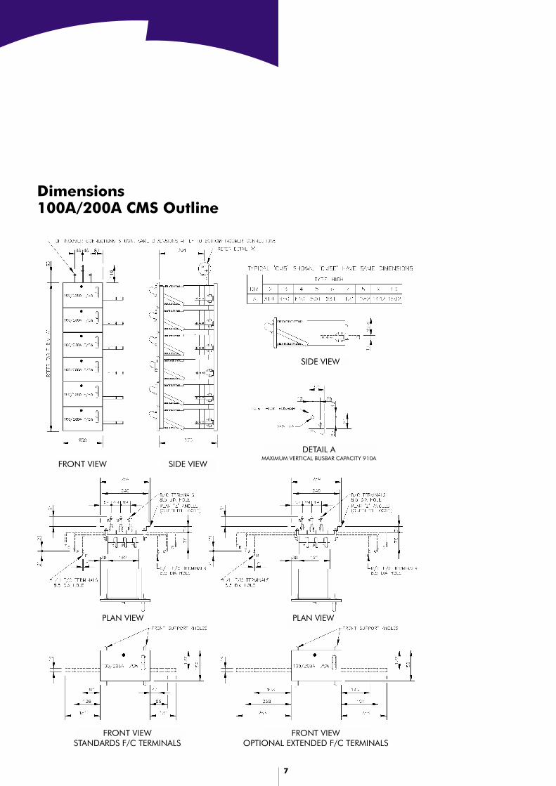
Dimensions100A/200A CMS Outline
FRONT VIEW SIDE VIEW
DETAIL AMAXIMUM VERTICAL BUSBAR CAPACITY 910A
PLAN VIEWPLAN VIEW
FRONT VIEWSTANDARDS F/C TERMINALS
SIDE VIEW
FRONT VIEWOPTIONAL EXTENDED F/C TERMINALS
8
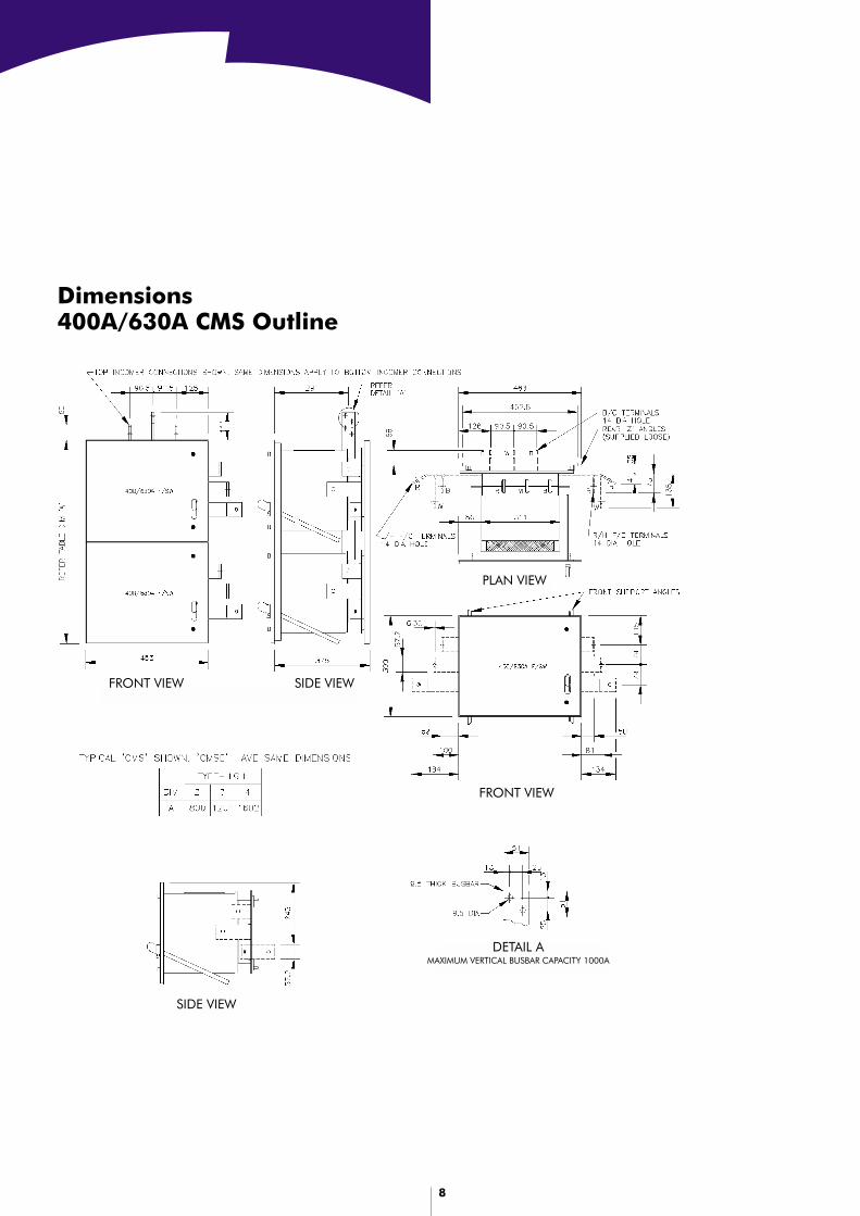
Dimensions400A/630A CMS Outline
PLAN VIEW
FRONT VIEW
SIDE VIEWFRONT VIEW
SIDE VIEW
DETAIL AMAXIMUM VERTICAL BUSBAR CAPACITY 1000A
9
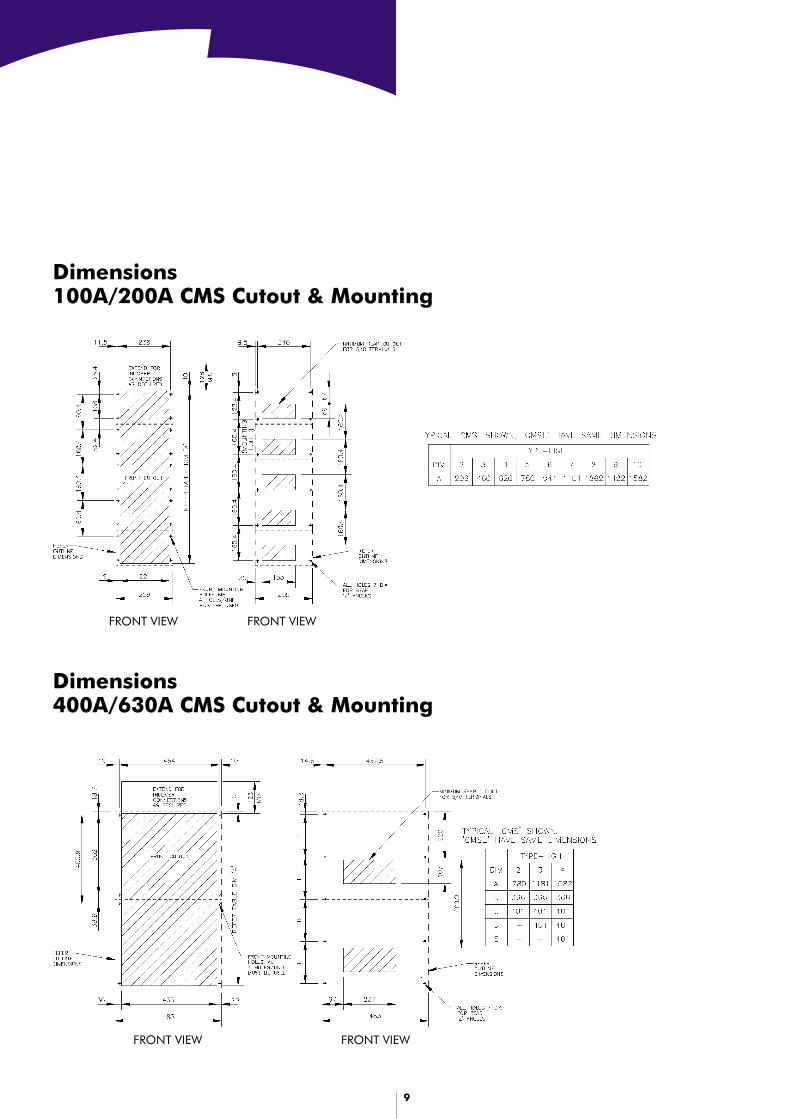
Dimensions100A/200A CMS Cutout & Mounting
Dimensions400A/630A CMS Cutout & Mounting
FRONT VIEW FRONT VIEW
FRONT VIEW FRONT VIEW
10
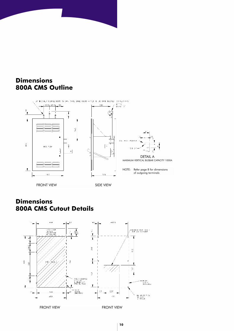
Dimensions800A CMS Outline
Dimensions800A CMS Cutout Details
DETAIL AMAXIMUM VERTICAL BUSBAR CAPACITY 1000A
SIDE VIEWFRONT VIEW
FRONT VIEW FRONT VIEW
NOTE: Refer page 8 for dimensionsof outgoing terminals
11
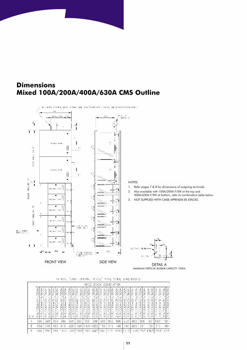
DimensionsMixed 100A/200A/400A/630A CMS Outline
FRONT VIEW SIDE VIEWDETAIL A
MAXIMUM VERTICAL BUSBAR CAPACITY 1000A
NOTES:
1. Refer pages 7 & 8 for dimensions of outgoing terminals
2. Also available with 100A/200A F/SW at the top and400A/630A F/SW at bottom, refer to combination table below.
3. NOT SUPPLIED WITH CMSE APPENDIX EE STACKS.
12
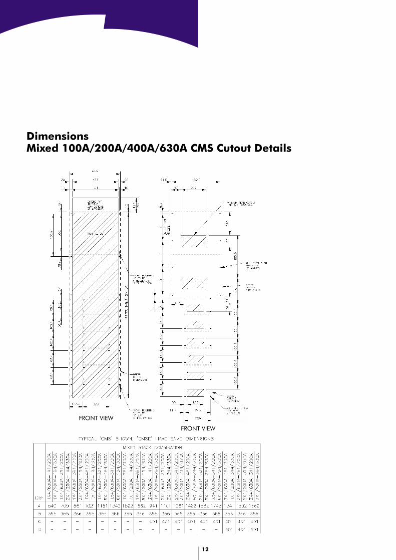
DimensionsMixed 100A/200A/400A/630A CMS Cutout Details
FRONT VIEW
FRONT VIEW
13
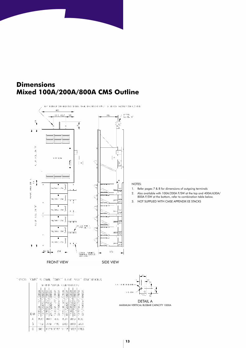
DimensionsMixed 100A/200A/800A CMS Outline
DETAIL AMAXIMUM VERTICAL BUSBAR CAPACITY 1000A
FRONT VIEW SIDE VIEW
NOTES:
1. Refer pages 7 & 8 for dimensions of outgoing terminals
2. Also available with 100A/200A F/SW at the top and 400A/630A/800A F/SW at the bottom, refer to combination table below.
3. NOT SUPPLIED WITH CMSE APPENDIX EE STACKS
14
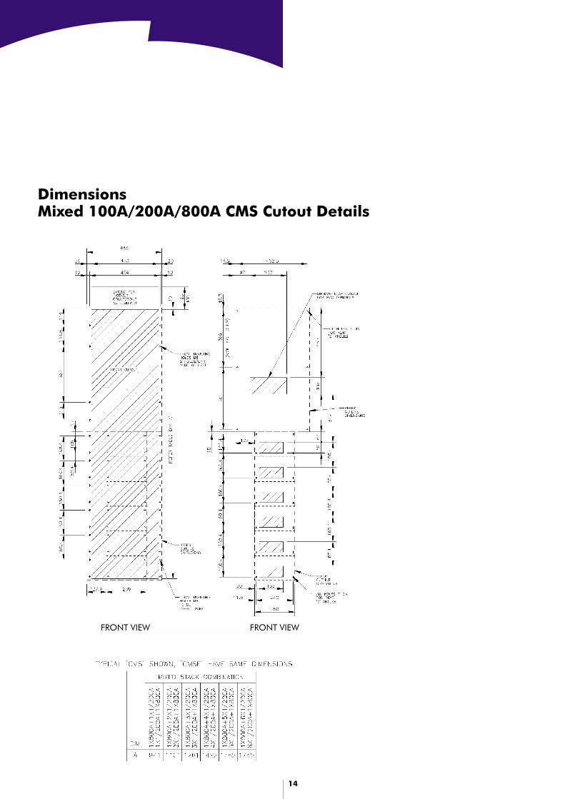
DimensionsMixed 100A/200A/800A CMS Cutout Details
FRONT VIEWFRONT VIEW
15
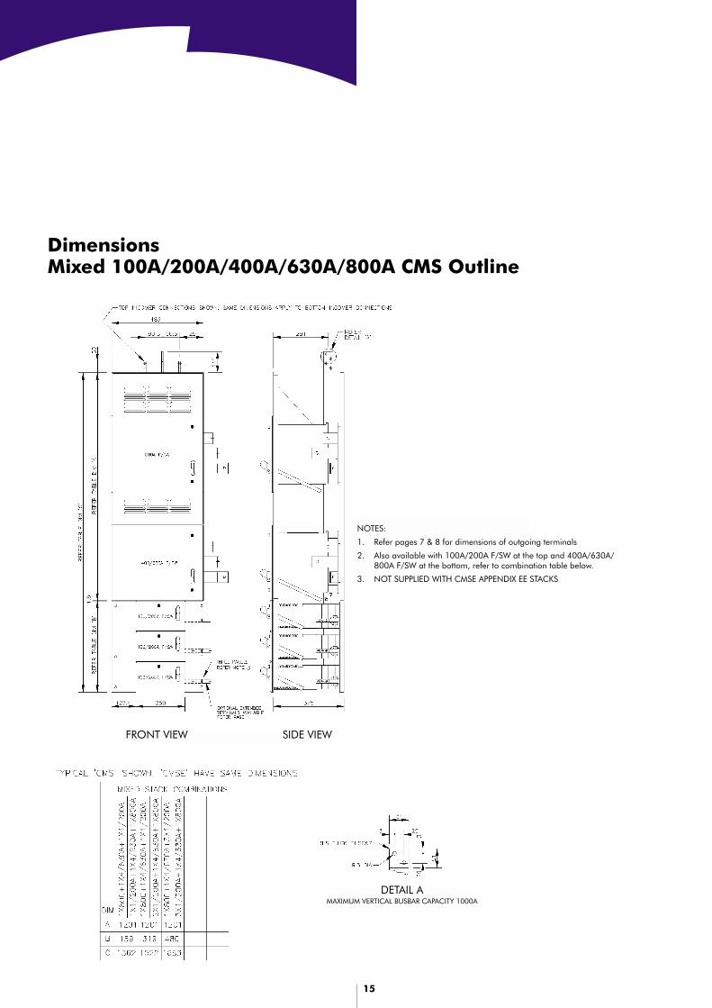
DimensionsMixed 100A/200A/400A/630A/800A CMS Outline
FRONT VIEW SIDE VIEW
DETAIL AMAXIMUM VERTICAL BUSBAR CAPACITY 1000A
NOTES:
1. Refer pages 7 & 8 for dimensions of outgoing terminals
2. Also available with 100A/200A F/SW at the top and 400A/630A/800A F/SW at the bottom, refer to combination table below.
3. NOT SUPPLIED WITH CMSE APPENDIX EE STACKS

16
DimensionsMixed 100A/200A/400A/630A/800A CMS Cutout Details
FRONT VIEW
FRONT VIEW
17
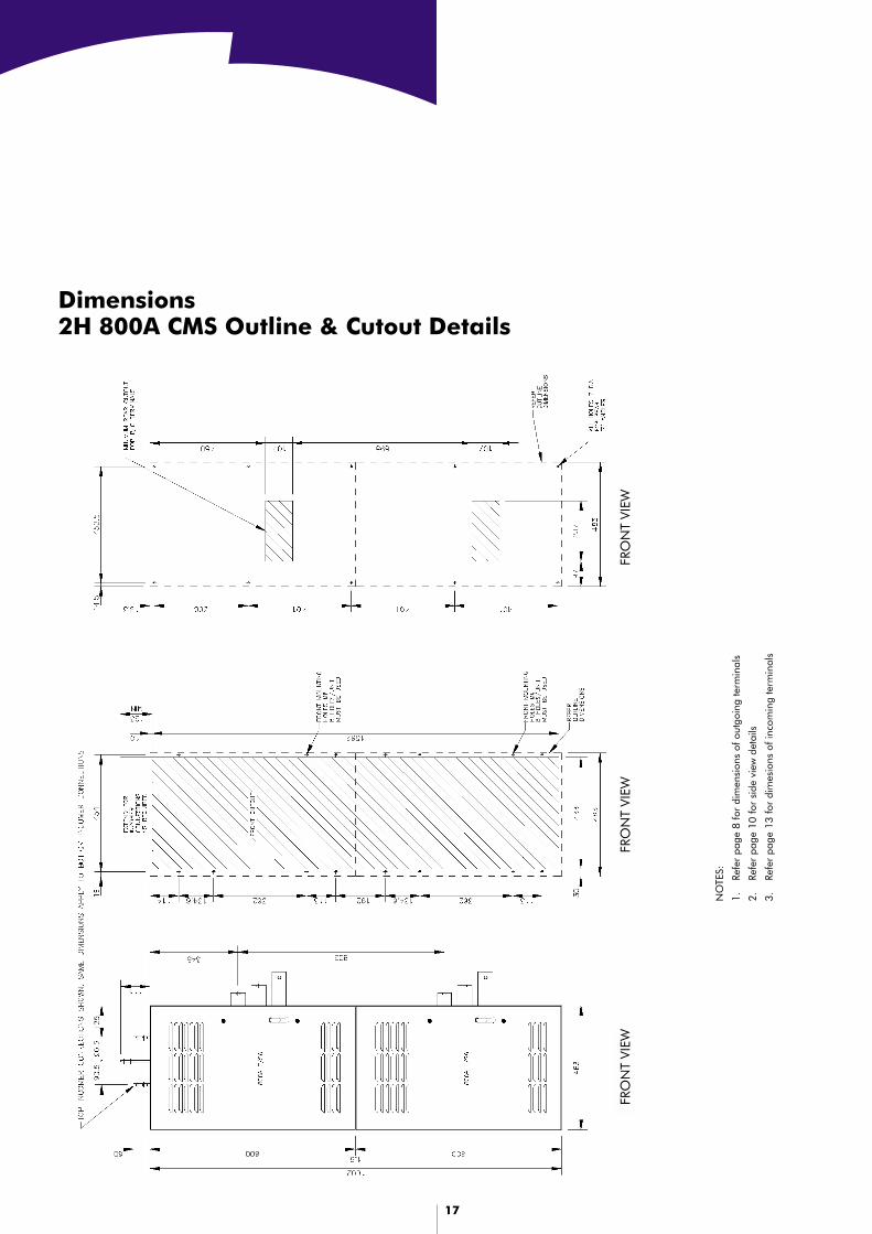
Dimensions2H 800A CMS Outline & Cutout Details
FRO
NT
VIEW
FRO
NT
VIEW
FRO
NT
VIEW
NO
TES:
1.Re
fer
page
8 fo
r di
men
sion
s of
out
goin
g te
rmin
als
2.Re
fer
page
10
for
side
vie
w d
etai
ls
3.Re
fer
page
13
for
dim
esio
ns o
f inc
omin
g te
rmin
als
18
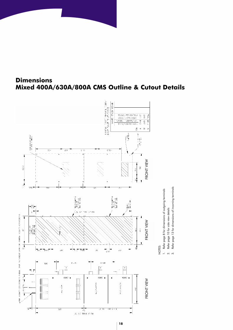
DimensionsMixed 400A/630A/800A CMS Outline & Cutout Details
NO
TES:
1.Re
fer
page
8 fo
r di
men
sion
s of
out
goin
g te
rmin
als
2.Re
fer
page
10
for
side
vie
w d
etai
ls
3.Re
fer
page
13
for
dim
ensi
ons
of in
com
ing
term
inal
s
FRO
NT
VIEW
FRO
NT
VIEW
FRO
NT
VIEW

19
Arcing Fault Containment CubicleConstruction Guide for 100A/200A CMSE
PLAN VIEW DETAIL A
SIDE VIEWFRONT VIEW(COVERS REMOVED FOR CLARITY)
SECTION VIEW ‘A–A’(LEFTHAND CABLE ZONE)
SECTION VIEW(RIGHTHAND CABLE ZONE)
VENT FLAP DETAIL
NOTES:
1. Refer page 7 for outline dimensions of fuseswitches
2. Use optional F/C extended terminals as required (L/H or R/H sides)
20
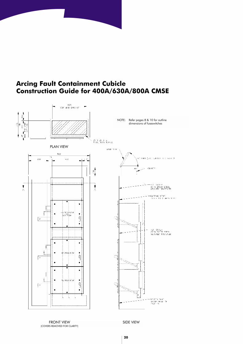
Arcing Fault Containment CubicleConstruction Guide for 400A/630A/800A CMSE
PLAN VIEW
FRONT VIEW(COVERS REMOVED FOR CLARITY)
SIDE VIEW
NOTE: Refer pages 8 & 10 for outlinedimensions of fuseswitches

21
Arcing Fault Containment CubicleConstruction Guide for 400A/630A/800A CMSE
SECTION VIEW ‘A–A’(RIGHTHAND CABLE ZONE)
SECTION VIEW ‘A–A’(LEFTHAND CABLE ZONE)
VENT FLAP DETAIL
DETAIL A
22
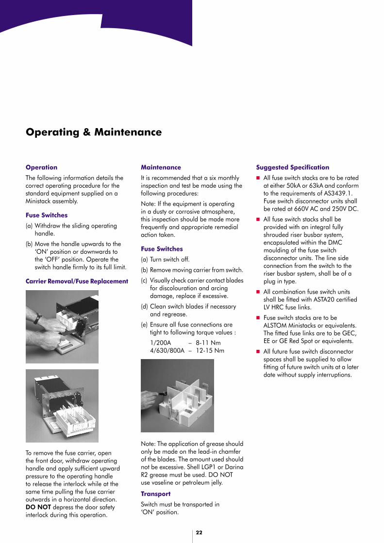
Operating & Maintenance
Suggested Specification
■ All fuse switch stacks are to be ratedat either 50kA or 63kA and conformto the requirements of AS3439.1.Fuse switch disconnector units shallbe rated at 660V AC and 250V DC.
■ All fuse switch stacks shall beprovided with an integral fullyshrouded riser busbar system,encapsulated within the DMCmoulding of the fuse switchdisconnector units. The line sideconnection from the switch to theriser busbar system, shall be of aplug in type.
■ All combination fuse switch unitsshall be fitted with ASTA20 certifiedLV HRC fuse links.
■ Fuse switch stacks are to beALSTOM Ministacks or equivalents.The fitted fuse links are to be GEC,EE or GE Red Spot or equivalents.
■ All future fuse switch disconnectorspaces shall be supplied to allowfitting of future switch units at a laterdate without supply interruptions.
Maintenance
It is recommended that a six monthlyinspection and test be made using thefollowing procedures:
Note: If the equipment is operatingin a dusty or corrosive atmosphere,this inspection should be made morefrequently and appropriate remedialaction taken.
Fuse Switches
(a) Turn switch off.
(b) Remove moving carrier from switch.
(c) Visually check carrier contact bladesfor discolouration and arcingdamage, replace if excessive.
(d) Clean switch blades if necessaryand regrease.
(e) Ensure all fuse connections aretight to following torque values :
1/200A – 8-11 Nm4/630/800A – 12-15 Nm
To remove the fuse carrier, openthe front door, withdraw operatinghandle and apply sufficient upwardpressure to the operating handleto release the interlock while at thesame time pulling the fuse carrieroutwards in a horizontal direction.DO NOT depress the door safetyinterlock during this operation.
Operation
The following information details thecorrect operating procedure for thestandard equipment supplied on aMinistack assembly.
Fuse Switches
(a) Withdraw the sliding operatinghandle.
(b) Move the handle upwards to the‘ON’ position or downwards tothe ‘OFF’ position. Operate theswitch handle firmly to its full limit.
Carrier Removal/Fuse Replacement
Note: The application of grease shouldonly be made on the lead-in chamferof the blades. The amount used shouldnot be excessive. Shell LGP1 or DarinaR2 grease must be used. DO NOTuse vaseline or petroleum jelly.
Transport
Switch must be transported in‘ON’ position.
23
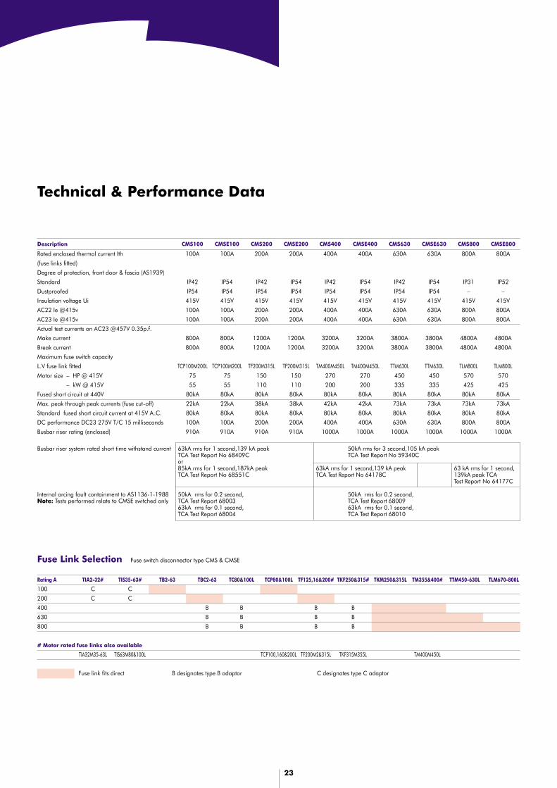
Fuse Link Selection Fuse switch disconnector type CMS & CMSE
Rating A TIA2-32# TIS35-63# TB2-63 TBC2-63 TC80&100L TCP80&100L TF125,16&200# TKF250&315# TKM250&315L TM355&400# TTM450-630L TLM670-800L
100 C C
200 C C
400 B B B B
630 B B B B
800 B B B B
# Motor rated fuse links also available
TIA32M35-63L TIS63M80&100L TCP100,160&200L TF200M2&315L TKF315M355L TM400M450L
Fuse link fits direct B designates type B adaptor C designates type C adaptor
Technical & Performance Data
Description CMS100 CMSE100 CMS200 CMSE200 CMS400 CMSE400 CMS630 CMSE630 CMS800 CMSE800
Rated enclosed thermal current Ith 100A 100A 200A 200A 400A 400A 630A 630A 800A 800A
(fuse links fitted)
Degree of protection, front door & fascia (AS1939)
Standard IP42 IP54 IP42 IP54 IP42 IP54 IP42 IP54 IP31 IP52
Dustproofed IP54 IP54 IP54 IP54 IP54 IP54 IP54 IP54 – –
Insulation voltage Ui 415V 415V 415V 415V 415V 415V 415V 415V 415V 415V
AC22 Ie @415v 100A 100A 200A 200A 400A 400A 630A 630A 800A 800A
AC23 Ie @415v 100A 100A 200A 200A 400A 400A 630A 630A 800A 800A
Actual test currents on AC23 @457V 0.35p.f.
Make current 800A 800A 1200A 1200A 3200A 3200A 3800A 3800A 4800A 4800A
Break current 800A 800A 1200A 1200A 3200A 3200A 3800A 3800A 4800A 4800A
Maximum fuse switch capacity
L.V fuse link fitted TCP100M200L TCP100M200L TF200M315L TF200M315L TM400M450L TM400M450L TTM630L TTM630L TLM800L TLM800L
Motor size – HP @ 415V 75 75 150 150 270 270 450 450 570 570
Motor size – kW @ 415V 55 55 110 110 200 200 335 335 425 425
Fused short circuit at 440V 80kA 80kA 80kA 80kA 80kA 80kA 80kA 80kA 80kA 80kA
Max. peak through peak currents (fuse cut-off) 22kA 22kA 38kA 38kA 42kA 42kA 73kA 73kA 73kA 73kA
Standard fused short circuit current at 415V A.C. 80kA 80kA 80kA 80kA 80kA 80kA 80kA 80kA 80kA 80kA
DC performance DC23 275V T/C 15 milliseconds 100A 100A 200A 200A 400A 400A 630A 630A 800A 800A
Busbar riser rating (enclosed) 910A 910A 910A 910A 1000A 1000A 1000A 1000A 1000A 1000A
63kA rms for 1 second,139 kA peakTCA Test Report No 68409Cor85kA rms for 1 second,187kA peakTCA Test Report No 68551C
50kA rms for 0.2 second,TCA Test Report 6800363kA rms for 0.1 second,TCA Test Report 68004
Busbar riser system rated short time withstand current
Internal arcing fault containment to AS1136-1-1988Note: Tests performed relate to CMSE switched only
50kA rms for 3 second,105 kA peakTCA Test Report No 59340C
63kA rms for 1 second,139 kA peakTCA Test Report No 64178C
63 kA rms for 1 second,139kA peak TCATest Report No 64177C
50kA rms for 0.2 second,TCA Test Report 6800963kA rms for 0.1 second,TCA Test Report 68010

8333
TAN
10/
02
INDUSTRIAL PRODUCTS25 Princes Road Regents Park NSW 2143
Tel: 1300 556 601 Fax: 1300 550 187 www.ip.alstom.com.au