Mining Operations - naalakkersuisut.gl/media/Nanoq/Files/Hearings/2010/20030… · Mining...
48
Angus & Ross plc - Nalunaq Gold Mine: Environmental Impact Assessment – 20 th July 2009 Section C2 Page 1 of 48 Mining Operations Mining Method The mining method proposed by A&R is based on inclined standard room-and pillar working up-dip on a 20% slope with final rhomboid pillars of 1.6m by 5.7m which will result in less dilution and higher recovery of gold than the previous NGM method. The initial operations of the mine over the first 12-18 months will concentrate on the winning of ore readily available in the existing stopes, mining of remnant pillars and ore from development mining headings together with treatment of the ore from the harbour stockpile. It has been identified that a considerable amount of fines (-50μm) gold remains in all the worked out stopes as ore dust. This dust be will cleaned up and won by sweeping, dinting and wash down by hydraulic methods to maximise overall gold recovery. The A&R cut-off grade of 7g/t as against the NGM cut-off grade of 15g/t releases upwards of 20K tonnes of previously out of grade ore. Ore won from the remnant pillars is expected to have a grade of 13g/t. This initial ore allows early positive operational cash flow. Full stope mining will then commence as development accesses and proves the new mining areas. Stope development will follow the following pattern: • Development of the stope perimeter headings (Development Mining); • Development drilling of the stope; • Ore production from the stope (Production Mucking); and • Backfilling of the worked out stope using waste rock from the mining and development operations. This progressive mining process is illustrated in Figure 12.3. All waste rock produced by the mining process and indeed from the process stream, including tailings, will be utilised in the system of backfilling the stopes. No waste of any sort will be removed from the mine.
Transcript of Mining Operations - naalakkersuisut.gl/media/Nanoq/Files/Hearings/2010/20030… · Mining...

Angus & Ross plc - Nalunaq Gold Mine: Environmental Impact Assessment – 20th July 2009
Section C2 Page 1 of 48
Mining Operations Mining Method The mining method proposed by A&R is based on inclined standard room-and
pillar working up-dip on a 20% slope with final rhomboid pillars of 1.6m by
5.7m which will result in less dilution and higher recovery of gold than the
previous NGM method. The initial operations of the mine over the first 12-18
months will concentrate on the winning of ore readily available in the existing
stopes, mining of remnant pillars and ore from development mining headings
together with treatment of the ore from the harbour stockpile. It has been
identified that a considerable amount of fines (-50µm) gold remains in all the
worked out stopes as ore dust. This dust be will cleaned up and won by
sweeping, dinting and wash down by hydraulic methods to maximise overall
gold recovery. The A&R cut-off grade of 7g/t as against the NGM cut-off
grade of 15g/t releases upwards of 20K tonnes of previously out of grade ore.
Ore won from the remnant pillars is expected to have a grade of 13g/t. This
initial ore allows early positive operational cash flow. Full stope mining will
then commence as development accesses and proves the new mining areas.
Stope development will follow the following pattern:
• Development of the stope perimeter headings (Development Mining);
• Development drilling of the stope;
• Ore production from the stope (Production Mucking); and
• Backfilling of the worked out stope using waste rock from the mining
and development operations.
This progressive mining process is illustrated in Figure 12.3.
All waste rock produced by the mining process and indeed from the process
stream, including tailings, will be utilised in the system of backfilling the
stopes. No waste of any sort will be removed from the mine.

Angus & Ross plc - Nalunaq Gold Mine: Environmental Impact Assessment – 20th July 2009
Section C2 Page 2 of 48
Figure 12.3 Diagrammatic Representation of Mining Method
Tailings/Backfill , Underground Water, Ventilation, and Geotechnical Design
Golder Paste Technology Europe Ltd have produced a comprehensive study
for NGM, dated 15th July 2009, of the tailings/backfill system, underground
water, ventilation and geotechnical considerations.
Golder Paste Technology Europe Ltd Report Limitations The study has been conducted at a preliminary stage in the NGM re-
development. As such some of the information or engineering detail
necessary to conclude the design is not yet available. The study has however
focused on the development of feasible operating solutions which will be
further defined as the mine nears operation and the necessary detail becomes
available.
This report was prepared for the exclusive use of Angus and Ross PLC. The
report, which specifically includes all tables, figures and appendices, is based
Angus & Ross plc - Nalunaq Gold Mine: Environmental Impact Assessment – 20th July 2009
Section C2 Page 3 of 48
on data and information received from Angus and Ross PLC and collected
during any previous work conducted by Golder Paste Technology (Europe) Ltd
(Golder PasteTec) and is based solely on the conditions of the property at the
time of the work, supplemented by historical information and data obtained
by Golder PasteTec as described in this report.
The services performed, as described in this report, were conducted in a
manner consistent with that level of care and skill normally exercised by other
members of the engineering and science professions currently practicing
under similar conditions, subject to the time limits and financial and physical
constraints applicable to the services.
Any use which a third party makes of this report, or any reliance on, or
decisions to be made based on it, are the responsibilities of such third parties.
Golder PasteTec accepts no responsibility for damages, if any, suffered by any
third party as a result of decisions made or actions based on this report.
The content of this report is based on information collected during our
investigation, our present understanding of the site conditions and our
professional judgement in light of such information at the time of this report.
This report provides a professional opinion and therefore no warranty is either
expressed, implied or made as to the conclusions, advice and
recommendations offered in this report. This report does not provide a legal
opinion regarding compliance with applicable laws. With respect to regulatory
compliance issues, it should be noted that regulatory statutes and the
interpretation of regulatory statutes are subject to change.
The findings and conclusions of this report are valid only as of the date of this
report. If new information is discovered in future work, Golder PasteTec
should be requested to re-evaluate the conclusions of this report and to
provide amendments as required.
Executive Summary
Angus and Ross PLC (A&R) are to undertake mining and mineral processing
activity within the underground Nalunaq Gold Mine (NGL). The mineral
processing, ore concentration, refinement, waste management and water

Angus & Ross plc - Nalunaq Gold Mine: Environmental Impact Assessment – 20th July 2009
Section C2 Page 4 of 48
management follows a different basis to that previously employed at NGM.
The mineral processing operations will consist of two phases undertaken in
the underground mine. The first phase is gravity based mineral processing
circuit and the second (additional) phase is a cyanide based mineral
processing circuit.
NGM intend to commence development based mining activity during the third
quarter of 2009, installing the first phase of the processing circuit in the
fourth quarter 2009. The second phase of the mineral processing circuit is
planned for installation and subsequent commissioning in early 2010.
The mineral processing activity generates liquid and solid materials which
have been identified and are described as process water with fines (tailings)
from the mineral processing and dust / fumes associated with the mining and
mineral processing.
Methodologies have been identified and preliminary design work undertaken
to manage these waste materials produced. The aim being to minimise
potential impact on the underground and surface environment that result
from the mineral processing operations in the NGM.
All process water and fines from the mineral processing circuit (tailings) will
be placed in previously mined areas in NGM. This is analogous to the
conventional placement of tailings as mine backfill in underground mining
operations. This application provides an effective means to fill old excavations
within the mine whilst minimising materials that need to leave the mine. The
tailings will be placed in old stopes with engineering controls designed and
built to provide an opportunity to drain water from the material over the
medium term thereby leaving the solids component in place in the mined out
stopes.
Underground mine water will be managed in a controlled fashion to minimise
discharge from the mine and maximise recirculation and recycling of the
water in the mining and mineral processing operations. Engineered systems
have been delineated to provide for appropriate means to control, clean and
transport underground mine water in the operations and where necessary to
discharge. These engineered controls are designed to handle the natural

Angus & Ross plc - Nalunaq Gold Mine: Environmental Impact Assessment – 20th July 2009
Section C2 Page 5 of 48
water flows recorded as well as those underground mine waters associated
with the tailings placement, mineral processing and other mining activity.
The ventilation system at NGM has adequate capacity to manage the airborne
dust and fumes associated with the mining and mineral processing activity.
The ventilation system requires minor modifications to fan locations and
ducting to manage ventilation flows adequately and ensure fresh air is blown
in and exhaust air blown out of working areas (including the mineral
processing area). A dust collection facility is recommended for the first phase
of the mineral processing circuit. The second phase processing requires
additional instrumentation, controls and procedures to be implemented to
mitigate concentrations of the fumes associated with the electro-winning and
chemicals associated with the leaching in the confined areas, ensuring these
are exhausting out of the general mine environment.
Introduction
Background
Angus and Ross PLC (A&R) is planning to undertake mining and mineral
processing activity within the underground Nalunaq Gold Mine (NGL). The
mineral processing operations will consist of two phases. The first phase will
be gravity based mineral processing circuit and the second phase a cyanide
based mineral processing circuit.
NGM intend to commence development based mining activity during the third
quarter of 2009, installing the first phase of the processing circuit in the
fourth quarter 2009. The gravity mineral processing circuit will be running for
approximately three months before commissioning the second phase of the
mineral processing circuit in 2010.
The mineral processing phases of activity generate liquid and solid materials
which have been identified during the design of the mining and mineral
processing system. Specifically these waste materials are described as:
• Process water with fines from the mineral processing (tailings); and
• Dust and fumes associated with the mining and mineral processing.

Angus & Ross plc - Nalunaq Gold Mine: Environmental Impact Assessment – 20th July 2009
Section C2 Page 6 of 48
Methodologies have been identified and preliminary design work undertaken
to manage these waste materials produced. The aim being to minimise
potential impact on the underground and surface environment that result
from the mineral processing operations in the NGM.
Approach
The approach undertaken has identified effective methods to manage the
process water and airborne waste materials generated by the mining and
mineral processing operations. These methods suit both the gravity based
and cyanide based phases of mineral processing activity.
The intent of this report is to provide descriptions of the adopted
methodologies that have been incorporated in to the design planning by A&R
for NGM.
A&R intend to advance these methods to manage waste to an appropriate
level of design. This will be done in parallel to the advancement of the mine
planning requirements toward the resumption of operations at the
underground mine.
A geotechnical appraisal has also been undertaken for the planned mineral
processing excavation within the NGM, recognizing the importance of this
planned infrastructure to the operations. The geotechnical appraisal provides
for stability analysis of the new excavation that incorporates the first and
second phases of the mineral processing system at NGM. This appraisal of the
preliminary design is included in this report.
Objectives
The objective of this report is to provide for a description of the solutions to
manage the waste materials within the NGM operations.
This report provides three sections addressing the management of waste
from the mineral processing and mining operations. The fourth section
provides for the geotechnical appraisal of the mineral processing excavation.
The sections are:

Angus & Ross plc - Nalunaq Gold Mine: Environmental Impact Assessment – 20th July 2009
Section C2 Page 7 of 48
• Tailings;
• Underground water;
• Ventilation; and
• Geotechnical.
Each section provides a description of the methodology to be implemented at
NGM to ensure efficient, safe, sustainable and effective management of its
operations and the environment. The report also provides details of the
preliminary design work for each aspect of the project.
Tailings
Tailings Management
Previously all ore was concentrated off site, removing any requirement to
handle post concentration slurried waste material (tailings). The operation will
concentrate and refine all the ore on site within the underground
environment, and therefore it is necessary to manage the tailings within the
underground mine. No external tailings storage facility is proposed. It is
understood that development waste, i.e. material not passing through the
concentration process will also be stored underground in previously excavated
stope areas however this is not the focus of this study.
The overriding objective of the tailings management is the placement of
material within the existing mined stopes, such that no tailings placement will
be required externally from the mine. Furthermore, consideration has been
given to minimising environmental, health and safety risk associated with the
storage of the tailings.
Methodology Overview
The concentration process and hence tailings generation will occur on the 300
Level some 340m from the portal. The process will include the comminution
of the gold bearing ore followed by gravity separation and then in 2010
additional cyanide based extraction process. To accommodate this latter
addition to the process train, this report has considered two phases, namely;

Angus & Ross plc - Nalunaq Gold Mine: Environmental Impact Assessment – 20th July 2009
Section C2 Page 8 of 48
• Phase 1 – Gravity based mineral processing; and
• Phase 2 – Cyanide based mineral processing.
Much of the engineering is similar between the two phases and is discussed
as such, however where differences occur between the phases, these are
noted. One key variation relates to production rate of the two concentration
phases, such that Phase 1 has a nominal capacity of 5tph, whilst Phase 2 will
operate at 10tph.
Tailings will be received from the gravity circuit (phase 1) or from a cyanide
destruction process (phase 2) but in each scenario the solids concentration is
likely to be similar. The relatively low rate of tailings production means it is
necessary to dilute the received tailings with additional water sourced from
the underground mine to enable effective pumping. This dilution will also
reduce any residual cyanide concentration in the tailings following the cyanide
destruction process, ensuring compliance with the International Cyanide
Management Code (Cyanide Code).
The tailings will be pumped into previously mined areas where future access
will not be required. Where necessary an engineered bulkhead will be
employed to retain the placed tailings, ensuring their controlled separation
from the operating mine. During the tailings placement water will either be
displaced or released from the tailings slurry and this will be accommodated
within the mine water management system.
Preliminary Tailings Management Design
Tailings Deposition Area Selection
An area has been identified within the mine for the placement of tailings as
backfill and is indicated in Figure 12.4. The area is located at the lower end of
the Target Block and extends from 280 Level through nominally to the 350
Level. The final elevation will be confirmed during later stage design work.

Angus & Ross plc - Nalunaq Gold Mine: Environmental Impact Assessment – 20th July 2009
Section C2 Page 9 of 48
Figure 12.4: Long Section of underground mine showing tailings backfill area
The area identified is considered suitable for the following reasons:
• The area below the 300 Level can be used for deposition without the
need for a bulkhead;
• The area is isolated, with access along a drive at the 300 Level and via
the footwall ramp only, limiting the risk from inundation;
• Once above the 300 Level the tailings can be retained with a single
bulkhead on the 300 Level access drive only;
• The ground below the filled area has no prospect of future mining
owing to a fault structure, therefore there is no risk of sterilizing future
ore;

Angus & Ross plc - Nalunaq Gold Mine: Environmental Impact Assessment – 20th July 2009
Section C2 Page 10 of 48
• The area is close to the main concentration area and at a similar
elevation, therefore minimizes pumping; and
• The area has been entirely mined and therefore no ore will be
sterilized within the tailings.
It is estimated that the area identified, if filled to the 350 Level, would offer
44,500m3 of storage capacity, equivalent to approximately one (1) year of
operation at the higher production rate described in the following section, and
shown in Table 12.1 below.
Table 12.1: Storage Capacities below 350 Level
Filling Area Stope Volume
(m3) Sill Drive Volume
(m3) Ramp Volume
(m3) Total Volume
(m3)
Below 300 Level 4,700 4,200 5,100 14,000
300 Level to 500 Level
13,600 8,000 8,900 30,500
Total 18,300 12,200 14,000 44,500
In completing the above storage assessment, the following assumptions have
been made:
• All void space will be filled such that no future access to the area will
be possible, including filling of the footwall decline ramp;
• The average true height of the mined out stopes is 1.7m;
• The sill drives have a cross sectional area of 10m2; and
• The decline ramp has a cross sectional area of 25m2.
An important assumption is the height of the stopes. A visual inspection of
some stopes indicates areas of overbreak which could increase the average
stope height, therefore increasing the available storage capacity. It is
recommended that a full volumetric survey of the proposed filling area be
completed to determine true stope volumes for mine planning and further
detailed engineering design purposes.
Angus & Ross plc - Nalunaq Gold Mine: Environmental Impact Assessment – 20th July 2009
Section C2 Page 11 of 48
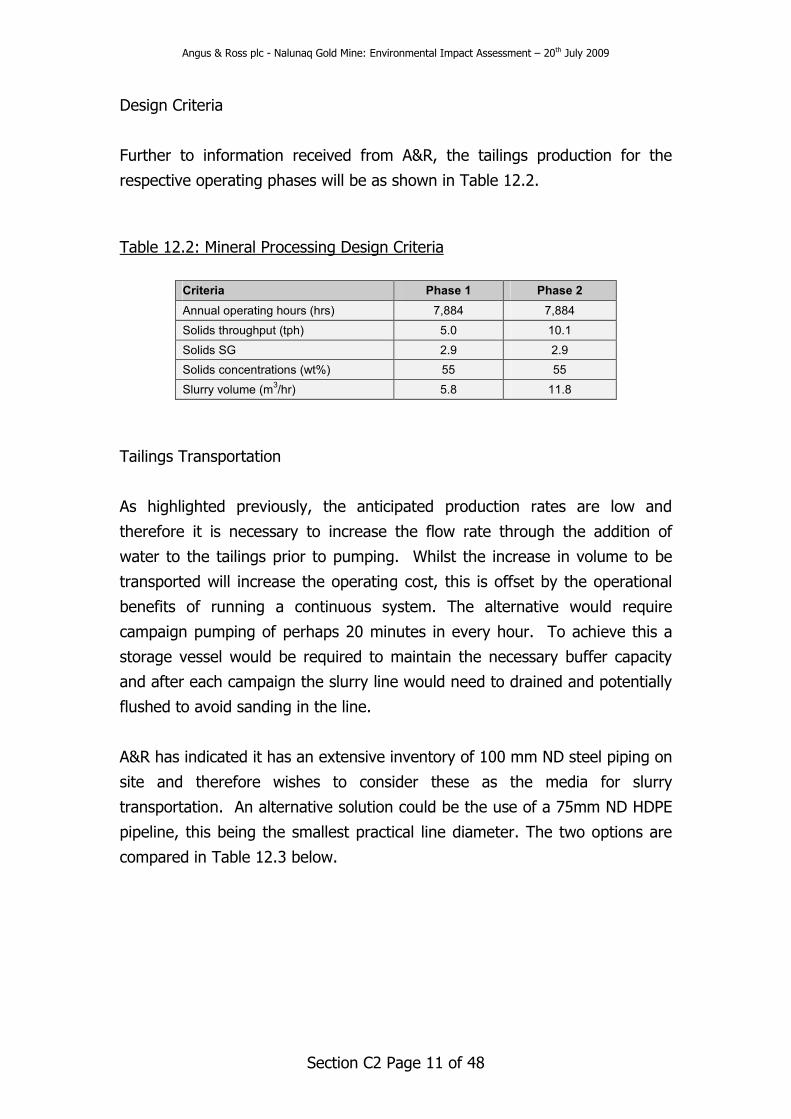
Design Criteria
Further to information received from A&R, the tailings production for the
respective operating phases will be as shown in Table 12.2.
Table 12.2: Mineral Processing Design Criteria
Criteria Phase 1 Phase 2
Annual operating hours (hrs) 7,884 7,884
Solids throughput (tph) 5.0 10.1
Solids SG 2.9 2.9
Solids concentrations (wt%) 55 55
Slurry volume (m3/hr) 5.8 11.8
Tailings Transportation
As highlighted previously, the anticipated production rates are low and
therefore it is necessary to increase the flow rate through the addition of
water to the tailings prior to pumping. Whilst the increase in volume to be
transported will increase the operating cost, this is offset by the operational
benefits of running a continuous system. The alternative would require
campaign pumping of perhaps 20 minutes in every hour. To achieve this a
storage vessel would be required to maintain the necessary buffer capacity
and after each campaign the slurry line would need to drained and potentially
flushed to avoid sanding in the line.
A&R has indicated it has an extensive inventory of 100 mm ND steel piping on
site and therefore wishes to consider these as the media for slurry
transportation. An alternative solution could be the use of a 75mm ND HDPE
pipeline, this being the smallest practical line diameter. The two options are
compared in Table 12.3 below.

Angus & Ross plc - Nalunaq Gold Mine: Environmental Impact Assessment – 20th July 2009
Section C2 Page 12 of 48
Table 12.3: Tailings Pipeline Selection
Pipeline Option Potential Advantages Potential Disadvantages
100 mm ND Steel
� A&R has an existing inventory
already on site
� Robust and common within the
mine
� Potentially more labour intensive to
install
� Poorer wear characteristics
� Greater water dilution required
therefore greater operating cost
75 mm ND HDPE
� Can be easier to install if laid at
the edge of a drive (with sandbags)
� Flexible enough to follow the
profile of the decline without
requiring couplings
� Better wear characteristics
� Will need to bought – no inventory
available
� Less robust – can be damaged
more easily by passing vehicles /
rocks
Based on the above table, either option presents worthy merits. A third
alternative maybe to use both steel and HDPE. The steel can be used in
areas of the mine subjected to heavy traffic use, where its robustness and the
option to hang it form the drive back would be of benefit. HDPE could then be
used where the piping runs through lower traffic areas, notably within the
footwall decline ramp adjacent to the identified tailings backfilling area. Traffic
here would likely be limited to inspection work only and thus the HDPE piping
could be laid on the floor of the drive with minimal protection. In addition,
the flexibility of the HDPE would enable quick installation around the curve of
the decline ramp.
Regardless of the line selection A&R make, the transportation of the slurry will
comprise the same components. The slurry will be received either from the
thickener, or from the cyanide destruction process at a suitably sized pump
box. The required water addition to achieve the necessary flow volume will be
introduced along with the tailings slurry to the pump box. Drawing from the
pump box will be two centrifugal slurry pumps, one duty and one standby. It
is expected that the necessary mixing of the slurry and the dilution water will
be achieved in the pump box and as the mixture passes through the pump
impeller, ensuring homogenous slurry leaves the pump discharge.
The modification to the flow volume will ensure the flow velocity within the
selected pipe will exceed the critical settling velocity, therefore mitigating the

Angus & Ross plc - Nalunaq Gold Mine: Environmental Impact Assessment – 20th July 2009
Section C2 Page 13 of 48
risk of sanding the line. Equally the flow velocity should not be so high as to
increase the wear rate of the pipeline.
The preliminary pipeline routes are shown in Appendices 12.1 and 12.2 are
identified as Route 1 and Route 2 respectively. Table 12.4 summarises key
data for the routes.
Table 12.4: Key Pipeline Data
Key Data Route 1 Route 2
Total Length (m) 602 814
Start Elevation (m) 312 312
Maximum Elevation (m) 312 362
Minimum Elevation (m) 293 293
Overall Elevation Variance (m) 19 19
Borehole requirement (m) 0 29
Route 1 presents an option for filling the stope areas below the 300 Level and
would be consider viable only before the introduction of the bulkhead. The
option takes the shortest possible route through existing infrastructure with a
reasonably consistent gradient.
Route 2 is designed to accommodate filling from the 300 Level up to the 350
Level. The route selected requires the installation of a single borehole to
connect from the 300 Level up to the main access ramp above. From here the
piping would run within the main access ramp until it reached the Target
Block decline. Following the target ramp decline down the pipeline would
access each sub-level from where tailings would be discharged.
Based on the pipeline route selection, Golder has completed some preliminary
hydraulic modelling based on the following assumptions:
• Design case represented by Route 2;
• A flow rate 42m3/hr;
• A relative slurry density range between 1.2t/m3 (21 wt% solids);
• Nominal 108mm ID pipeline (steel and HDPE assumed to be similar in
characteristics);
• NPSH (Net Positive Suction Head) – 1m; and
• Pipeline routes as per Appendices 12.1 and 12.2.
Angus & Ross plc - Nalunaq Gold Mine: Environmental Impact Assessment – 20th July 2009
Section C2 Page 14 of 48
Based on these assumptions, the following pumping characteristics and duties
can be reported:
• Total discharge head (TDH) – 60m;
• Maximum pump flow rate – 42 m3/hr;
• Anticipated pump selection – Warman 3 x 2 or similar; and
• Estimated operating power – 10 kW per pump.
Tailings Deposition
The tailings deposition will be a staged process, accounting for the period of
time when deposition is below the 300 Level and then above it. This process
can be described in five stages, namely:
• Stage 1 – Dewater the currently flooded area beneath the 300 Level
and prepare the areas for receiving backfill;
• Stage 2 – Place backfill within the area below the 300 Level;
• Stage 3 – Before completion of Stage 2 the bulkhead along the 300
Level access drive should be constructed;
• Stage 4 – Commencing filling the area above the 300 Level behind the
bulkhead; and
• Stage 5 – Complete filling to the designated elevation.
The area identified below the 300 Level is currently flooded and therefore this
water should be removed in advance of tailings placement. The water will be
pumped from the flooded area and directed to the mine water management
system. Once dewatered, the area is to be inspected and prepared to receive
backfill.
Tailings deposition is then commence. It is proposed that the tailings will be
discharged from a single point from the sub-level immediately above the
stope being filled. As a result of the need to dilute the tailings it is expected
that there will be a brisk release of water from the deposited tailings, and this
coupled with groundwater naturally occurring will result in the sub-aqueous
disposal of the tailings. To optimise rapid settlement of the solids, the
discharge pipeline should be extended as far into the stope (down dip) as
possible. It will be necessary to review the discharge location to ensure even
deposition of material across the strike length of each stope and maximise

Angus & Ross plc - Nalunaq Gold Mine: Environmental Impact Assessment – 20th July 2009
Section C2 Page 15 of 48
placement and backfilling of the old stopes voids. A number of discharge
locations are to be considered for each sub-level.
It is anticipated that the area below the 300 Level will fill with supernatant
water swiftly and as further tailings are deposited, the displaced water will be
allow to travel down the 300 Level access drive where it will be intersected by
the mine sedimentation system which is described further below. This
operation will continue until such time as the area below the 300 Level is full
and the water being displaced does not contain excessive suspended solids.
Prior to completion of filling below level 300 Level, it will be necessary to
construct a bulkhead within the 300 Level access drive which will act to retain
material once it is stored above the 300 Level. A description of the bulkhead
is provided below. During construction it will be necessary to ensure dry
working conditions within the 300 Level access drive and hence excess water
within the lower levels will need to be mechanically removed with a pump
rather than being allowed to simply be displaced by gravity. A submersible
pump or similar may be employed to pump water via a pipe back to a suitable
location where it can run back to the mine sedimentation trap whilst avoiding
the bulkhead construction area. Once the bulkhead is construction is complete
water can again run by gravity as the bulkhead will be design to allow the
controlled passage of water through it.
Once the bulkhead is completed filling from the sub-level above the 300 Level
can begin and in doing so the storage of tailings can advance above the 300
Level. The method for placement of tailings here will be similar to that
described above; however the water management will vary.
Two principle options are available to manage the water. The first simply
allows the water to fill up upon the placed tailings until such time as access to
the deposition sub-level becomes compromised, at which time mechanical
extraction of the water is required. A second, and potential more passive
solution would be the installation of a decant (penstock) type system within
the inclined stopes. The design will be such that is would discharge by gravity
through the bulkhead to the 300 Level access drive.

Angus & Ross plc - Nalunaq Gold Mine: Environmental Impact Assessment – 20th July 2009
Section C2 Page 16 of 48
A preliminary concept for such a solution would see a large diameter pipe
pass through the bulkhead and then extend to the just below the first sub-
level above the 300 Level. As tailings are discharged from this sub-level and
the supernatant water level rises above the tailings, excess water would be
collected within the decant, thereby preventing the water level from
exceeding the level of the decant.
Once the tailings level reaches a height at which the supernatant quality is
compromised, then the decant is to be extended to the next sub-level and the
former sub-level abandoned. Tailings deposition would then commence from
the new sub-level and thus the process would be repeated. The system
would also ensure that the maximum height of supernatant water would be
controlled by the height between the sub-levels.
Once filling of the entire area is complete, then the decant pipe should is cut
off as close to the tailings level as possible, thereby preventing the
development of excessive standing water in the placed tailings in perpetuity.
The design and specification for such a decant system are not within the
scope of this study and therefore they should be developed in the next stage
of the design.
Bulkhead Design
The bulkhead will be installed on the 300 Level drive to isolate the tailings
storage from the 300 Level portal drive. The bulkhead will be installed along
the 300 Level exploration drive, although the exact location of the bulkhead
will be determined following examination of the ground conditions within the
drive. The bulkhead is the primary engineered structure retaining the tailings
based backfill with residual water in the older stoping area as previously
discussed.
The design of bulkhead requires consideration of a number of elements to
ensure its appropriateness as an engineered structure to control the forces
acting on it and the environment in which it is constructed and in contact
with. Thus, a range of factors are considered in its design.

Angus & Ross plc - Nalunaq Gold Mine: Environmental Impact Assessment – 20th July 2009
Section C2 Page 17 of 48
Design Considerations
The potential failure mechanisms for bulkheads retaining the unconsolidated
fill (tailings) are described below.
• Shear failure of the bulkhead and rock interaction as a result of pore
pressures resulting in shear through the rock, through the concrete, or
along the rock-concrete interface;
• High hydraulic gradient near the bulkhead resulting in leakage through
the rock mass;
• Stress redistribution (or induced) stresses created as a result of the
excavation around the drive perimeter; within the immediate rock
itself;
• Hydro-fracturing mechanisms can pose a potential problem under
some circumstances if the fill pressure exceeds the minor principal
stress in the rock mass away from the immediate influence of the drift
(i.e. that is not subjected to consolidation grouting), and this results in
the opening or creation of fractures that transmit water and tailings to
the downstream side of the bulkhead; and
• Chemical attack may reduce the integrity of concrete over time.
These aspects have been reviewed during the preliminary design determined
for the NGM tailings deposition.
Design Parameters
The bulkhead is planned to be located beneath a 35° inclined stope and will
be constructed to retain tailings up to a vertical height of 50m.
The following design parameters have been considered for design of the
bulkhead:
• The drift has a rectangular geometry 3.5m wide by 3m high (Area =
10.5m2 and Perimeter = 13m);
• Nominal vertical height of fill to bulkhead ≅ 50m;
• Tailings head (assumed saturated unit weight = 0.023MN/m3) at
bulkhead location = 1.15MPa

Angus & Ross plc - Nalunaq Gold Mine: Environmental Impact Assessment – 20th July 2009
Section C2 Page 18 of 48
• Vertical Rock Cover ≅ 100m;
• The topography above the bulkhead is at a slope of approximately 20°;
• Maximum acceptable hydraulic gradient for longevity = 12
(~118kPa/m), corresponding to about 2(RMR – 5) = 2(64 - 5);
• Conservative rock-concrete interface shear strength of 0.15MPa for
rock-concrete interface without grouting; and
• Overall Safety Factor of at least 3.0 required for permanent bulkhead
longevity.
Rock Mass Description
The main orebody consists of quartz veining ranging up to 1m in width,
located within predominant lithologies of mafic metavolcanics and dolerites.
The orezone has an average plunge of 35° to the southeast, and is located
beneath the east dipping face of a glaciated valley.
Based on the previous Golder report, the rock mass quality for the host mafic
volcanics was assessed as having a mean RMR (Bieniawski, 1976) of 64 and
values ranging from 56 (worst case) to 72 (best case), which classifies as fair
to good rock mass quality. The intact rock shows an average uniaxial
compressive strength (UCS) of 131MPa.
Mapping of the rock masses in the vicinity of the planned bulkhead site will be
required so that the Nalunaq mine can assess the rock mass quality, rock
mass fabric, and estimate the intact rock strength. The Norwegian
Geotechnical Institute’s (NGI) Q-System and Bieniawski’s Rock Mass Rating
system, RMR76 (Bieniawski, 1976) should be used to classify the rock mass
quality. Field assessment of the intact rock hardness should be made
according to guidelines described in ISRM, 1981.
Preliminary Bulkhead Design
A parallel (monolithic and “unhitched”) type of bulkhead is considered to be
most appropriate for this preliminary design at NGM.
The main bulkhead design parameter is the length of concrete that needs to
be cast in the drift to ensure a stable structure. It must comply with all

Angus & Ross plc - Nalunaq Gold Mine: Environmental Impact Assessment – 20th July 2009
Section C2 Page 19 of 48
conditions discussed previously in this section; the selected length for the
parallel bulkhead will be that which corresponds to the most critical of these
five considerations.
Figure 12.5: Preliminary design concept for a bulkhead for tailings backfill
The design details and consideration will be advanced to a detailed design
requirements as further work and data is assessed for the NGM as per
previous discussions regarding the commencement of operations. In this
further work, full design details and considerations will be made available for
review presentation. For indicative purposes only at the stage in design,
Figure 12.5 provides some details on the design concept. Based on the
previous Golder report, there are no in situ stress measurements at the
Nalunaq mine. The initial in situ stresses are assumed to be represented by
the ratio of horizontal stress to vertical stress (k) of 2. The vertical stress is
assumed to be equal to the unit weight (0.027 MN/m3) of the rock, multiplied
by the depth below surface. In addition, simplified two dimensional numerical
analyses indicated that simulation of unloading due to glacial melting and
erosion might have caused a rotation of the in situ stresses, with the
projected horizontal component being equal to 0.9. Additional numerical
Angus & Ross plc - Nalunaq Gold Mine: Environmental Impact Assessment – 20th July 2009
Section C2 Page 20 of 48
analyses will be required during the next phase of the bulkhead design to
better estimate the induced stresses around the bulkhead.
Re-handling of Tailings
It is understood that prior to the installation of the phase 2 mineral
processing circuit, a portion of gold will be retained within the tailings and
thus will need to be reintroduced to the concentration circuit once the phase
2 circuit is in operation. To facilitate this, the temporary storage of tailings will
need to be achieved in such a way that it can be extracted and returned to
the circuit.
The material will be stored either in a new excavation specifically designed for
the purpose, or in an existing drive. Ideally the location will be a slight to
moderately declining drive capable of containing approximately 15,000 m3 of
material assuming storage for three months of operation.
Once the material has been extracted and reprocessed, the excavation could
act as an intermediate and emergency sedimentation trap, and would become
part of the mine water management system or if planned appropriately form
any other part of the future mine development planning and operational
requirements.
Long-term Life of Mine Storage
It is estimated that the currently identified storage area would offer
approximate two years of capacity at the proposed extraction rate. Additional
capacity will be required in the future and additional areas can be identified
with similar characteristic to that of the currently proposed option and these
should be incorporated in the overall life of mine planning and design.
Underground Water
Mine water management at NGM focuses on managing the quantity and
quality of water within the mine and exiting the mine. The inclusion of an
underground concentration plant presents the opportunity to recycle ground
water efficiently within the underground environment, minimising the quantity

Angus & Ross plc - Nalunaq Gold Mine: Environmental Impact Assessment – 20th July 2009
Section C2 Page 21 of 48
of water abstracted from other sources, and also the amount of water
discharged from the mine.
The water management focuses around a central water collection and
sedimentation pond, where water from within the mine can be retained and
re-circulated for use either in the mine, for the process or discharge
externally. The correct design and sizing of the system will minimise
suspended solids, thereby leading to an improvement in the current
arrangement. This controlled management of the water within the mine,
including specially design sedimentation traps will be used to minimise
sediment loading within water discharged from the mine.
Conceptual Water Balance
A conceptual mine water balance has been developed to determine the
average flows into, within and out from the mine. Using this water balance it
is possible to develop preliminary estimations of where the water will flow
within the mine and necessary controls and management required.
The water balance has been developed through limited site data, information
from A&R and a series of assumptions. The site data was limited to two years
of monitoring of mine water outflow. The water flow was observed within the
valley beneath the 300 Level portal, and recorded using a V-notch weir. The
results from that monitoring are shown on Figure 12.6 below.
Figure12.6: Mine Water Flow Data

Angus & Ross plc - Nalunaq Gold Mine: Environmental Impact Assessment – 20th July 2009
Section C2 Page 22 of 48
Based on the above data, an average flow from the mine equalled 64m3/hr,
which includes all natural groundwater inflows and operational uses such
drilling water. Based on this information, the mass balance data from A&R
and an understanding of the future mining method and equipment operation,
the following assumptions have been developed and used in the water
balance modelling:
• Natural ground water inflow (average) – 50m3/hr;
• Equipment water – 15m3/hr;
• Other mine operational use (e.g. washing faces) – 10m3/hr;
• Recycle water for processing – 36m3/hr;
• All process water will report to tailings;
• Tailings will consolidate to 80wt% solids in the stopes;
• All water will be directed to the 300 Level; and
• Excess water will be released from the mine following sedimentation.
Based on the above assumptions, the preliminary water balance has been
developed and is shown in Figure 12.7 below.

Angus & Ross plc - Nalunaq Gold Mine: Environmental Impact Assessment – 20th July 2009
Section C2 Page 23 of 48
Figure 12.7: Preliminary Water Balance
From the model it is clear that within the mine there will be a recirculation of
water, leading from the clean water pond to the concentration circuit, to the
tailings and then back to the clean water pond. Within this circulation, it is
assumed that only water retained within the tailings will be lost from the
circuit. Additionally the model assumes that all water used within the mine for
drilling etc will return to the clean water pond without loss. Consequently the
mine water inflow approximately equates to the mine water outflow, less the
water held within the tailings.
It should be noted that the model makes not allowance for the attenuation of
water within mine between source and receptor. For example the model
assumes that water used by a drill rig will immediately report to the clean
water pond. This may have implications when considering short times frames
of several hours where water may be extracted from the clean water pond
but may not return for 24 hrs, leading to a potential for short-term draw
down of the clean water pond. This issue would be mitigated by the inclusion
Retained in Stope
3 m3/hr
2 m3/hr 38 m3/hr 38 m3/hr
36 m3/hr 35 m3/hr
Clean Water Pond
0 m3/hr 110 m3/hr
Mine Water Inflow Equipment Use
50 m3/hr 15 m3/hr
Operations Use
10 m3/hr
49 m3/hr
Mine Outflow
Top Up Water
Fresh Water Process Plant
Process Water
Tailings Slurry
Bleed Water
Angus & Ross plc - Nalunaq Gold Mine: Environmental Impact Assessment – 20th July 2009
Section C2 Page 24 of 48
of “top up” water which could be abstracted to cover any short-term issues
that may occur infrequently in the operation.
Water Handling Systems
The water handling system is developed around a central mine water
collection and sedimentation pond. The objective of this will be to retain
adequate water within the mine to avoid the need for additional water to be
pump in from the existing borehole located in the valley, but also to minimise
suspended solids, the latter being essential for both use with equipment
underground, and the responsible release of water to the environment when
discharged from the mine as may be required.
Appendix 12.3 shows the proposed design for the water handling system.
Water enters the system at the mouth of the declining ramp. Once within the
large body of very slow moving water the sediments will fall from suspension
and be retained at the base of the ramp. Water is then extracted from the
sump at the far end of the decline, minimising disturbance to the settled
solids. At times it is assumed the solids will need to be removed, and under
these conditions the water level would be drawn down to allow the removal
the settled material. This material would be re-handled within the processing
plant, thereby ensuring its eventual storage within the tailings. This “clean
up” process would likely be completed within the normal maintenance shut
down period and thus would not impact on the operation of the mine.
Alternative a second identical system may be installed allowing the first to be
taken out of service without compromising the mining or concentration
processes.
It is proposed that the water handling system be developed along the 300
Level portal drive, with all water from upper levels being directed to this level.
Using the above water balance it is possible to estimate the minimum
required retention time in the sump to ensure adequate removal of
suspended solids. Golder has assumed an eight hour residence time as
adequate for this purpose, and thus at the average inflow rate to the trap
predicted by the water balance, an overall capacity of 884m3 is required. The
design presented on Appendix 12.3 provides for a capacity of 1000m3.

Angus & Ross plc - Nalunaq Gold Mine: Environmental Impact Assessment – 20th July 2009
Section C2 Page 25 of 48
The data and anecdotal evidence suggests that high flows are expected
during the spring thaw. In light of this the necessary capacity and / or
number of systems installed should be reviewed during further detailed
design and ongoing operation. Effort should also be placed on developing a
water monitoring system. Such as system is described further below.
Mine Water Control and Discharge
As indicated by the preliminary water balance, it is anticipated that water will
continually be discharged from the mine as is currently the case. The
approached described herein is how NGM will manage the discharge of that
water, which is something that is considered to be an improvement on the
previous operation at NGM.
Water has been observed to exit the mine on at least two levels; however the
majority discharges through the 300 Level portal. Through proper control of
water flowing within the mine, water will be managed such that it is
discharged through a single portal only, namely the 300 Level. The
underground mine water management system is designed to collect water
close to its source in small inter-level sediment traps (sumps), possibly on
each sub-level. A simplified sketch of such a sump is shown in Figure 12.8
below for information.
Figure 12.8 – Inter-level Sedimentation Sump (Typical Cross Section)
The location of each sump can be determined after NGM complete a
comprehensive survey to identify the sources of major water course entries to
the mine. Conceptually a suspended submersible pump would transfer
collected water to the central water handling system on the 300 Level,
however the details for achieving this not provided for in this report. The
Drive
Submersible pump

Angus & Ross plc - Nalunaq Gold Mine: Environmental Impact Assessment – 20th July 2009
Section C2 Page 26 of 48
option to utilise gravity may be an option, but where possible water should be
run in pipes from each sedimentation sump, allowing the mine control over
the water route and eventual discharge location.
Once water enters the central water handling system, suspended solids will
be removed. The water balance confirms that there will be an excess of water
and thus an overflow from the central water system will be necessary. This
overflow is currently predicted to be approximately 50m3/hr, a reduction on
the currently estimated discharge from the mine. Water will overflow from the
sump end of the central water system ensuring it passes through the
sedimentation process, and will pass immediately into a culvert or closed pipe
to control its flow to the portal. Once at the portal, the water flow would
enter an oversized pipe to control its flow into the valley floor, where it will be
discharged in to the existing arrangements that NGM has in place.
Monitoring and Emergency Response Planning
As described previously, the current records for water entry into and out of
the mine are scant. A new and robust system is recommended to be
developed to monitor where and how water enters the mine, the flow across
all seasons and finally the quality of the water as it exits the central water
system. This monitoring should at least record the suspended solids content,
pH and electrical conductivity. In addition, a regime should be developed to
monitor the cyanide levels within supernatant water released from the tailings
which should complement the normal monitoring of cyanide within the
concentrator.
It is not known at the time of reporting what emergency response plans are
in place at the mine, however it is important the that the water management
is considered within in these as well as on its own. Issues to be considered
may include:
• Unexpected inflows of water to the mine, inundating the central water
handling system;
• Excessive sediment release from the central water system;
• High cyanide levels within the water when operating the CIL process;
and

Angus & Ross plc - Nalunaq Gold Mine: Environmental Impact Assessment – 20th July 2009
Section C2 Page 27 of 48
• Portions of the mine wide water system freezing.
Ventilation
Introduction
A review has been undertaken of the existing ventilation system at the NGM.
This is based on the ventilation survey undertaken when the mine was in full
scale operations in November 2008.
The following methodology is the basis of an effective underground mine
ventilation system and the basis of this work. Flow through ventilation is the
main ventilation circuit for the NGM. Fresh air enters the mine from surface
via a shaft, ventilation raise or adit. The fresh air is distributed through the
mine via internal ventilation raises and ramps, and flows are controlled by
regulators and mounted ventilation fans. An auxiliary ventilation system takes
air from the flow-through system and distributes it to the mine workings via
ventilation fans, venturis and disposable fabric or steel ducting. The key
requirements of a ventilation system is to maintain an appropriate volume
and flow of fresh air to the working environment underground and thus to
ensure dirty air is exhausted in a controlled fashion out of the underground
mine.
This report is a technical review of the ventilation system at the underground
mine. Specifically the review has included the following elements:
• To review of the status of the current ventilation system for
maintaining adequate ventilation in the mine;
• To determine the required ventilation system for the proposed mining
blocks; and
• To provide general considerations for future mining activity including
the proposed mineral processing facility.
The ventilation review focuses on the three proposed mining blocks, referred
to as:
• ‘A-B’ Southern Mining Block (SB) - down dip of general operations;
• ‘C’ Mountain Block (MB) - up dip of general mine operations; and
Angus & Ross plc - Nalunaq Gold Mine: Environmental Impact Assessment – 20th July 2009
Section C2 Page 28 of 48
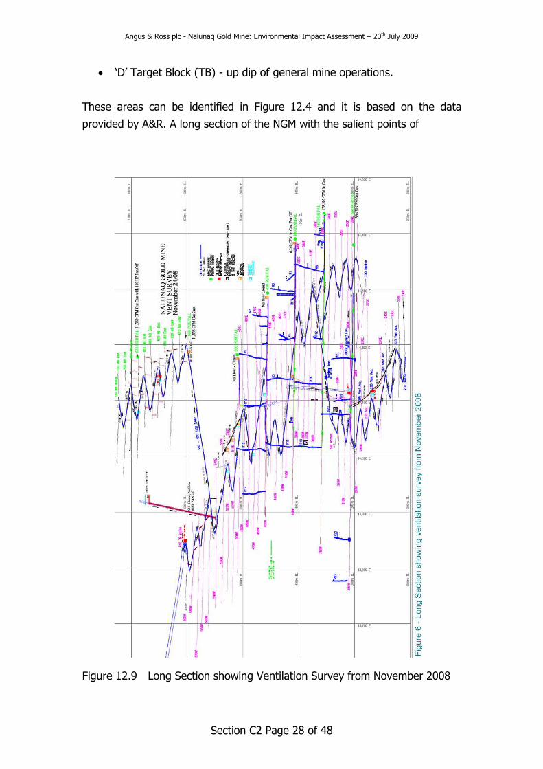
• ‘D’ Target Block (TB) - up dip of general mine operations.
These areas can be identified in Figure 12.4 and it is based on the data
provided by A&R. A long section of the NGM with the salient points of
Figure 12.9 Long Section showing Ventilation Survey from November 2008

Angus & Ross plc - Nalunaq Gold Mine: Environmental Impact Assessment – 20th July 2009
Section C2 Page 29 of 48
the ventilation survey from 2008 is shown in Figure 12.9. The proposed
mining plan and mining equipment to be used underground in the operations
start up in 2009/2010 has also been incorporated in to the review.
For the purposes of maintaining an appropriate and recognised standard of
underground mine working environment the ventilation requirements have
been based on those detailed in the Canadian Ontario Mining Regulations
(1990) for underground mines.
Diesel Equipment
Diesel equipment is of prime significance to generating an understanding of
the ventilation demand in the NGM operation like all other mines. Table 12.5
summarises the proposed mobile equipment NGM intends to use in the
operation. This data is the basis for the diesel equipment analysis in the
ventilation demand assessment.
Table 12.5: Diesel equipment, power rating and air volume requirements
Equipment
Model Type Kilowatts M3 per second
JS 350 Loader 136 8.2
JS 220 Loader 75 4.5
JDT 413 Haulage Truck 102 6.1
JDT 415 Haulage Truck 136 8.2
MJM 21B 3 Boom Jumbo 69 4.1
MJM 20B 2 Boom Jumbo 46 2.8
M5700DTC Kubota Tractor 43 2.6
Longhole Drill Basket Drill 2.8
Note: Diesel equipment information received from NGM.
To obtain ventilating air volume requirements for diesel equipment, the
Canadian Ontario Mining Regulations (1990) were used (i.e. 0.06 m3 per
second per kilowatt).
Diesel Equipment Requirements per Mining Block
The mine plan at NGM is intending to work the three mining blocks previously
discussed. A number of diesel powered mobile mining equipment is to be

Angus & Ross plc - Nalunaq Gold Mine: Environmental Impact Assessment – 20th July 2009
Section C2 Page 30 of 48
utilised for the mining operations. For any given mining block activity the
equipment to be utilised and associated ventilation requirements are
estimated in Table 12.6.
Table 12.6: Diesel equipment and airflow per mining block
Volume Equipment Model and Type Number of Units Total Air Required
(M3/sec)
JS350 Loader 2 16.3
JDT 415 Haulage Truck 2 16.3
MJM 21B Drill Jumbos (3 Boom) 3 12.4
Total Mining Block Air Volume
Requirement - 45.1
On the basis that the equipment listed above is the maximum utilised in any
mining block and a further two trucks are utilised to provide ore haulage from
the mining block to the mineral processing facility an additional air flow
volume is required as below:
• JDT 415 trucks x two (ramp haulage) = 16.3m3/sec
Thus a total ventilation requirement is estimated at 61.4m3/sec for the
underground mine.
The mine ventilation survey data reported by NGM in November 2008 details
a total air volume in to the underground mine of 87.3m3/sec. As such there is
an acceptable and adequate level of air flow into the mine with the current
system for the proposed mining plan.
The intent is to mine the three mining blocks consecutively as resource and
mine planning indicates this to be an efficient approach. It is worthwhile to
note that if future mine planning recognised a need to work the three mining
areas at the same time with three times the amount of equipment in each
block a total ventilation volume demand rises to 134.5m3/sec plus 16.5m3/sec
ramp haulage giving a total demand of 151.0m3/sec.
The current ventilation system should be maintained efficiently to minimise
energy consumption and maximise its effectiveness in the underground
operations. This can be maintained by:

Angus & Ross plc - Nalunaq Gold Mine: Environmental Impact Assessment – 20th July 2009
Section C2 Page 31 of 48
• Periodic ventilation surveys;
• Planned ventilation control inspections and maintenance programmes;
• Erecting ventilation brattice or regulator controls on all disused drives
and stoping areas to prevent short circuiting of any components of the
system; and
• Erecting controls to ensure the intake (fresh) air circuit is separated
from the exhaust ventilation circuit.
If further volume requirements are recognised through refinements in mine
planning or a need to operate additional development headings additional
options to those described above can be implemented in the underground
operations to increase capacity of the system. These include:
• Portals from 450 to 500 Level be closed for airflow, unless required for
access (which should be controlled to minimise circuit losses);
• Seal all inactive levels, if there is any losses of air from the ramp; and
• Run the fans on the 600 Level and/or the 680 Level portals (turned off
in the November 2008 survey), to increase the exhaust air from the
mine. Then taking volume and pressure readings on these fans to
incorporate in to the overall ventilation system demand and supply
balance.
The following points have been considered in this preliminary design review of
the system:
• The 350 Level portal to ramp is clear for airflow;
• The 400 Level portal to ramp is clear for airflow;
• The main ramp is connected to 350 Level;
• Mining will be carried out in the A-B block, C block and D block only;
• The mine intake (fresh) air volume is presently supplied from 350 Level
ramp portal, with a minor volume from the 400 Level ramp portal;
• The November 2008 survey data tabulated presents a discrepancy
between intake and exhaust volumes in the survey; and
• The largest power rated requirements for a given piece of diesel
equipment was used to determine air volume requirements.

Angus & Ross plc - Nalunaq Gold Mine: Environmental Impact Assessment – 20th July 2009
Section C2 Page 32 of 48
Overall Ventilation Requirements for Mine Production Areas
Ventilation for ‘A-B’ Southern Stoping Block
To provide sufficient ventilation volumes for mining the Southern stoping
block, a total of 61.4m3/sec is required to be delivered by downcasting the
ramp from 350 Level. There are two options discussed below to manage the
ventilation requirements.
Option 1
To down cast 61.4m3/sec on the ramp it will be necessary to exhaust the 225
Level through the 225/300 ventilation raise to the 300 Level and exhaust the
ramp portal on 300 Level. This would require the installation of exhaust fans
at the top of the 225/300 raise on 300 Level (fan sizes to be determined
based on raise size). Level connections to the 225/300 ventilation raise
between 300 and 225 Level must be sealed. Install two 1.2m diameter
113kw auxiliary ventilation fans on the ramp just above the 225 ventilation
access and duct with 1.2m diameter ducting from each fan down the ramp
and into the Southern stope block. This would require rigid wall duct with
1.2m diameter 113kw booster fans on each line, every 245m. These fans
would supply a design air volume of 61.4m3/sec to the southern stoping block
and the ramp for truck operation. This option assumes the mineral processing
area is ventilated from the Number 20 raise. The details of this option can be
seen in Appendix 12.4.
Option 2
If the surface ramp is developed to 210 Level before mining commences, then
the surface ramp from 210 Level can be used for exhaust air rather than the
225/300 raise. This would reduce the system resistance considerably and
therefore lower fan horsepower requirements (i.e. install 1.2m fans at the
entrance to the stoping block and therefore no fans and ducting required on
the ramp). Exhaust air fans should be installed at the proposed surface ramp
portal (two 1.2m diameter 113kw) fans to exhaust 61.4m3/sec). All
connections to the 225/300 ventilation raise should be sealed with brattice
work or other appropriate controls. The details of this option can be seen in
Appendix 12.5.
The following assumptions have been made regarding ventilation of this
block:

Angus & Ross plc - Nalunaq Gold Mine: Environmental Impact Assessment – 20th July 2009
Section C2 Page 33 of 48
• All other mining areas are idle;
• The largest power rated requirements for a given piece of diesel
equipment was used to determine air volume requirements;
• The top of the 225 ventilation raise breaks into 300 Level; and
• The proposed ramp from surface will break into 210 Level.
Ventilation for the ‘C’ Block (Mountain Block) Mining Area
To provide sufficient air volumes for mining the ‘C’ block, a total of
61.4m3/sec is required to exhaust the 720 Level. There are two options
discussed below to manage the ventilation requirements.
Option 1
To provide sufficient air for mining the ‘C’ stoping block, install a 3m2 raise
from 720 Level to surface (27m perpendicular distance) and exhaust through
this raise. It will be necessary to install an exhaust fan at the raise bottom on
720 Level and seal the 680 Level ramp portal. The 75kw fan on 680 Level at
the ramp portal may be sufficient for this purpose and could be relocated to
the bottom of the new raise. This fan should be started in the near future so
as to permit the collection of volume and pressure readings and thereby
enhance the ventilation data available as the bench mark for the NGM. Two
1.2m diameter 113kw fans should be installed at the ramp top on 720 Level
(MB) and run with twin 1.2m diameter ducting into the stoping area. The
details of this option can be seen in Appendix 12.6.
Option 2
Install two 1.2m diameter 113kw fans just below 680 Level and run 1.2m
diameter rigid wall ventilation ducting from these fans into the ‘C’ stoping
block on 720 Level. Booster fans ((113kw) will be required every 245m on
each line. Airflow is to exhaust back down the ramp to 680 portal.
In this case a design air volume of 61.4m3/sec is required to ensure sufficient
air for trucks on the ramp above 680 Level. The 75kw fan presently on 680
Level may be suitable as it is currently reported as not in use.

Angus & Ross plc - Nalunaq Gold Mine: Environmental Impact Assessment – 20th July 2009
Section C2 Page 34 of 48
An airtight brattice work ventilation control is also recommended to be
installed on the 610 incline (TB) to ensure sufficient air volume upcasts the
ramp from below.
As per the November 2008 ventilation survey, there is sufficient air volume on
the 730 (MB) incline to complete development of the exhaust air raise. The
details of this option can be seen in Appendix 12.7.
The following assumption has been made regarding ventilation of this block:
• All other areas in the mine are idle; and
• There are presently no raise breakthroughs from 720 Level (MB) to
surface.
General Ventilation for the ‘D’ Block (Target Block) Mining Area
To provide sufficient air volumes for mining the ‘D’ block, a total of
61.4m3/sec is required. There are two options discussed below to manage the
ventilation requirements.
Option 1
To provide sufficient air volumes for mining the ‘D’ block a drive to connect
the 610 (TB) incline to the 540 raise (in the refuge station area) is required to
be developed to draw air up the 610 (TB) incline and exhaust to the 540
raise. The 75kw fan presently on the 540 raise may be adequate for this
purpose. As commented previously, it is expedient to operate this fan as soon
as possible and measure fan air volumes and pressures to provide
confirmation for detailed mine planning and ventilation requirements in the
future. Airtight ventilation brattice work should be installed on the 550-600
east ramp just above the 610 incline connection to ensure an upcast on the
main ramp from below the 610 connection. Two 113kw fans should be
installed on the 610 ramp just below the proposed connection drive with twin
1.2m diameter ducting into the stoping area. The details of this option can be
seen in Appendix 12.8.
To develop the connection drive, a 30kw fan could be installed on the 610
incline just above the proposed drive and run a 0.9m diameter ducting into
the drive. This would provide sufficient air.

Angus & Ross plc - Nalunaq Gold Mine: Environmental Impact Assessment – 20th July 2009
Section C2 Page 35 of 48
Option 2
Install two 1.2m diameter 113kw fans just below 610 incline, on the main
ramp, and run 1.2m diameter rigid wall ventilation ducting from these fans
into the ‘D’ stoping block. Booster fans (113kw) will be required every 245m
on each line. In this case a design air volume of 61.4m3/sec is required to
ensure sufficient air for trucks on the ramp incline. The airflow (61.4m3/sec)
will exhaust back down the ramp and to 680 portal. The details of this option
can be seen in Appendix 12.9.
The following assumptions have been made regarding ventilation of this
block:
• All other areas in the mine are idle; and
• There is no raise breakthrough at the top of the 610 ramp (incline) to
surface. NGM should confirm there is no surface system connection at
the top of the 610 (TB) incline;
• Surface photographs show a 670 ventilation raise breakthrough to
surface. This raise may be at the top of the 610 (TB) ramp incline, in
which case it may be used as an exhaust raise rather than developing
a connection drive to the 540 raise. This is to be investigated further
by NGM as the mine planning details develop; and
• As per the November 2008 air survey (17.9m3/sec), there is sufficient
air down casting the 610 (TB).
Typical Mining Block Ventilation
To ventilate a typical mining block 56m3/sec is required. This includes a factor
of 25% to account for leakage and losses. This equates to the installation of
two 1.2m diameter 113kw fans in the upstream side of the mining block and
running 1.2m diameter ducting from the fans. Each ventilation duct line will
supply one-half the total air volume. Each 1.2m diameter ventilation duct can
be split into three headings using ventilation duct laterals (i.e. routing of
ducting dependent on sequence of mining).
Thereby giving the capability to ventilate six headings with fresh air. It makes
intuitive sense that if fewer headings are worked at any point in time the local
circuit may be made more efficient by not leaving fans on to unused headings

Angus & Ross plc - Nalunaq Gold Mine: Environmental Impact Assessment – 20th July 2009
Section C2 Page 36 of 48
or working areas. Conversely if more headings are worked consecutively then
more fresh air intake is required in to the area.
Ventilation controlling brattice work should be installed in connection slots as
required, to direct airflow through the active areas of diesel mobile equipment
operations. This requires frequent inspections by appropriate personnel to
ensure adequate ventilation of mining areas as is reasonable and expected in
the mining operation. The details of this option can be seen in Appendix
12.10.
Mineral Processing Ventilation
The development of the additions mine openings for gravity phase of the
mineral processing location will require 40 horsepower (30kw) fan at the
bottom of the number 20 raise on 300 Level and ducting from the fan into the
crushing/mill area. The fan and ducting will supply 15.9m3/sec to the crusher
area as per 300 to 400 Level plan. Airflow must exhaust to the 300 Level
portal.
A dust collector (bag house) will be required in the crushing area with a
pickup point over the crusher. Air exhausted from the bag house can
recirculate in the crusher room.
The cyanide mineral processing phase in 2010 will require exhausting the air
to the 300 Level portal to mitigate the potential of minor cyanide processing
associated fumes escaping into the mine atmosphere if the pH of the leaching
process drops. Air monitors are to be installed in the mineral processing
vicinity to ensure detention of any such conditions is promptly made and
mitigated. This area must have a continuous supply of ventilating air of
approximately 2.4m3/sec. Procedures for remedial action are to be developed
and implemented if cyanide processing associated fumes are encountered.
If measures are to be taken to control the release of HCN gas into the mine
environment, the waste pass can be used to draw (fresh) air from the 300
Level portal and through the mineral processing area. This will then become
exhaust air after passing through the area. An exhaust fan will be required at
the top of the waste pass to exhaust 8.3m3/sec. This will then require
appropriate ventilation controls to ensure the exhaust air from the mineral

Angus & Ross plc - Nalunaq Gold Mine: Environmental Impact Assessment – 20th July 2009
Section C2 Page 37 of 48
processing chamber is then channelled through a controlled exhaust system
out of the underground mine.
In the case of the waste pass being utilised as the exhaust (and drawing in
fresh air from the 300 portal) the 225/300 raise must be used as an intake
raise with the two 1.2m 113kw fans on the ramp at the raise bottom to be
installed in an airtight wall. These will draw fresh air down the 225/300 raise
from the 300 Level portal. The air will need to be ducted with two rigid wall
ventilation ducts, with booster fans every 245m on each line into the lower
mining blocks. Air is to exhaust through the main ramp until such time as the
planned lower mining block surface portal is installed which can then be
utilised as an exhaust.
The fan sizes required will be determined for the 225/300 raise and the waste
pass based on the geometry of these raises. It is likely the waste pass
exhausting a small volume of air would require a fan in the size range of 0.9m
diameter 5.3kw. Details of this option can be seen in Appendix 12.10.
The limited amount of electro winning that will take place with the mineral
processing activity in NGM is undertaken in a controlled environment whereby
the fumes are exhausted in to a controlled and sealed conduit. This conduit
should be connected to ventilation duct and an exhaust fan to ensure the
electro winning fumes are force ventilated out of the mine through the
exhaust ventilation circuit.
Ore Pass Ventilation
Install a 0.9m 22.5kw fan on the main ramp just west of the 450 Level
breakthrough and run a 0.9m diameter duct into the orepass access drive.
This will supply 14.2m3/sec to the orepass drive. If the orepass dump is on
450 Level, a fan and duct are not required.
Lower Mining Block Development Ventilation
Install a 1.2m 75kw fan 9m from the ramp entrance and run 1.2m diameter
ventilation ducting from the fan down the ramp for development mining. This
will supply 18.9m3/sec to the face, which is sufficient air for a loader and
truck. Details of this option can be seen in Appendix 12.11.

Angus & Ross plc - Nalunaq Gold Mine: Environmental Impact Assessment – 20th July 2009
Section C2 Page 38 of 48
Recommendations
The following recommendations are provided on the basis of the analysis
undertaken and the discussion presented in the previous sections of this
report.
Southern ‘A-B’ Mining Block
Develop the proposed ramp from surface and install two 1.4m 56.3kw
exhaust fans at the portal to exhaust air from the south mining block to
surface.
Mountain ‘C’ Mining Block
Develop a 3m2 raise from 720 Level to surface and install two 1.4m 56.3kw
fans at the bottom of the raise to exhaust air to surface.
The 75kw fan at the 680 portal may be adequate and could be relocated.
This fan should be operated to permit the acquisition of volume and pressure
measurements as soon as possible to support any decision on its suitability.
Target ‘D’ Mining Block
Develop a connection drive from the 610 ramp (beginning of the ‘D’ block
mining area) to the 540 raise and install two 1.4m 56.3kw fans in the
connection drive. This will up-cast the 610 incline and exhaust into the 540
raise to surface provided that there is no raise breakthrough at the top of the
610 ramp incline. Note: The 75kw fan presently at this raise may be adequate
(volume and pressure measurements required to confirm suitability).
Crusher Ventilation
Intake air to be supplied from the fan at number 20 raise and duct in the
crusher area. Air to exhaust to the 300 Level portal where 8.3m3/sec is
required. The fan should be started and volume and pressure readings taken
to confirm suitability.

Angus & Ross plc - Nalunaq Gold Mine: Environmental Impact Assessment – 20th July 2009
Section C2 Page 39 of 48
Geotechnical
Introduction
The mineral processing plant and operation requires additional excavation
space in the NGM.
Based on the preliminary design of the mineral processing excavations an
appropriate level of geotechnical analysis has been undertaken to assess the
ground control requirements for the excavation. Preliminary confirmation is
provided that excavation sizes are permissible and ground control
requirements have been provided to manage risk to an acceptable level.
Mineral Processing Chamber Excavation
The mineral processing chamber consists of a range of existing and new
drives to be developed in the NGM. The mineral processing area in the NGM
can be seen in Figure 12.10. It is approximately 80m below the footwall of
the orebody and is located on the 300 Level. Note – some mine openings and
the surface contour has been excluded from the view to ensure clarity.
Figure 12.10 – Isometric view of horizontal and vertical development.
The existing drives form the major component of the gravity based mineral
processing circuit. The new drives to be designed and excavated are
predominantly for the chemical based mineral processing circuit. These form a
large chamber in the new excavation measuring approximately 12m wide,
300 Portal Mineral Processing
Chamber

Angus & Ross plc - Nalunaq Gold Mine: Environmental Impact Assessment – 20th July 2009
Section C2 Page 40 of 48
12m high and 65m long. Figure 8 provides a plan view of the existing drives,
proposed drives and an indication of the general mineral processing plant
layout in the mineral processing chamber. A larger scale drawing of the
excavation with key dimensions and plant details can be seen in Appendix
12.12. Figure 12.11 shows the excavation geometry in plan view. Appendix
12.13 shows the excavation with all the plant and equipment removed.
The current crushing chamber is approximately 845m2 in plan area. The
additional plan area stripped, slashed and developed under the proposed
design provides an additional 1,245m2. This provides a total plan area of
approximately 2,090m2 for the mineral processing chamber. This represents
an increase in plan area of some 247% on that currently in place.
Figure 12.11 - Plan view of mineral processing chamber excavation

Angus & Ross plc - Nalunaq Gold Mine: Environmental Impact Assessment – 20th July 2009
Section C2 Page 41 of 48
Data Input and Review
The geometric data has been supplied by A&R for the existing mine geometry
and the proposed additional excavation geometry to accommodate the
mineral processing plant. In addition, A&R have provided the geological
description from the Kvaerner Feasibility Study (2002) and the Golder
Associates Geotechnical Audit (2004) for the NGM. These were commissioned
by the previous owners of the NGM. The material in these reports is not
repeated in this document and as such the reader should consider reviewing
these documents for their content.
The evaluation of the geotechnical and geological data is based on the reports
and data available through a desk study nature of assessment.
The data recorded from orebody and infrastructure geological and
geotechnical mapping data in 2000 and 2004 is summarised in the 2004
Golder Associates Geotechnical report and of key note is the general
commentary of the rock mass classification as being in the range ‘fair’ to
‘good’ with a mean Q value of 4. Low and high Q values range from 1 to 22.
The Q system of empirical rock mass classification is not discussed in length
in this report, but for a sense of context the following salient points are made
(Hoek, 2007):
On the basis of an evaluation of a large number of case histories of
underground excavations the Norwegian Geotechnical Institute proposed a
Tunnelling Quality Index (Q) for the determination of rock mass
characteristics and tunnel support requirements. The system has been used
extensively in mining and civil engineering tunnels (or drives). The numerical
value of the index Q varies on a logarithmic scale from 0.001 to a maximum
of 1,000 and is defined by:
Q = RQD x Jr x Jw
Jn x Ja x SRF
Where:
RQD is the Rock Quality Designation
Jn is the joint set number
Jr is the joint roughness number

Angus & Ross plc - Nalunaq Gold Mine: Environmental Impact Assessment – 20th July 2009
Section C2 Page 42 of 48
Ja is the joint alteration number
Jw is the joint water reduction factor
SRF is the stress reduction factor
The rock tunnelling quality Q can now be considered to be a function of only
three parameters which are crude measures of:
Block size (RQD/Jn)
Inter-block shear strength (Jr/ Ja)
Active stress (Jw/SRF)
The Q system goes on to evaluate and provide estimates on the ground
control requirements for any given excavation based on over 1000 case
histories.
Using the data reported in the 2004 Geotechnical Audit coupled to the
preliminary excavation design for the mineral processing chamber, the ground
control requirements are assessed. Table 12.7 provides a summary of the key
points to the analysis of the excavation. Summary Q data from the 2004
reporting is included in this report in Appendix D.
Table 12.7 – Summary of key points from the Q system analysis for drives
Description Value Comments
Mean Q 4.37 Range from 1 to 22
ESR 1.6 For long term / permanent mine infrastructure
MU Span 5.8m Maximum unsupported span estimate
Bolt Length 1.8m Range from 1.6m to 2.8m
Bolt Spacing 1.5m Ring and in-line spacing dimensions
Table Notes:
• Mean Q – is taken from the values reported in the 2004 report. This is
summarized in the last page of the Appendix D;
• ESR – the value of 1.6 is used. This is representative for permanent
mine openings, water tunnels for hydro power (excluding high pressure
penstocks), pilot tunnels, drives and headings for large excavations;
• ESR – the value used in the 2004 work is between 3 and 5. This is
representative of temporary mine openings and not relevant to the
analysis of this mine infrastructure;
Angus & Ross plc - Nalunaq Gold Mine: Environmental Impact Assessment – 20th July 2009
Section C2 Page 43 of 48
• ESR – NGM may wish to review the inclusion of an ESR of 1.3 when
final design details are confirmed, as this infrastructure is intended to
be relatively free from ground control risk. An ESR value of 1.3 is used
for storage rooms, water treatment plants, minor road and railway
tunnels, surge chambers and access tunnels. The use of an ESR of 1.3
equates to a smaller maximum unsupported span and bolts of 2.1m in
length;
• MU Span – the maximum unsupported span permissible is estimated
based on the equation below:
Maximum span (unsupported) = 2 ESR Q0.4
• Bolt Length – the bolt length is estimated for a range of excavations
width and 1.8m length is quoted for a drive size of 5.4m width. The
estimation is based on the equation below:
L=[2 + (0.15B)]/ESR
Where B = excavation width
Bolt spacing – the bolt spacing estimate is scaled from the chart in Figure 9.
This equates to in-line and ring spacing of the bolts.
It should be noted that the application of the Q system is largely based on the
assumption that the orientation of the excavation has been designed such
that it is at its most favourable orientation towards any faults and joints that
may form wedges and blocks in the excavation. This is not confirmed as the
case and as such a level of risk is presented by the larger size excavations in
the mineral processing chamber. As such recommendations are made for
ground control requirements to be installed and further site based assessment
to be undertaken to confirm ground control requirements.

Angus & Ross plc - Nalunaq Gold Mine: Environmental Impact Assessment – 20th July 2009
Section C2 Page 44 of 48
Figure 12.12 – Q system chart showing Q value of 4 and a range of drive
spans
Preliminary Recommendations
Based on the review of the previous geotechnical assessment data, the
update of the Q assessment and the proposed mineral processing chamber
geometry the following recommendations are made:
• All backs of the excavations within the mineral processing chamber are
bolted with 1.8m long fully encapsulated rock bolts, with surface plates
and tensioned. Spacing at 1.5m intervals;
• Bolting is to extend across the back of the excavations and into the
shoulder;

Angus & Ross plc - Nalunaq Gold Mine: Environmental Impact Assessment – 20th July 2009
Section C2 Page 45 of 48
• The larger excavations (over 6m in width) as shown in Appendix D
12.14 and 12.15 are recommended to be bolted with 6m long fully
encapsulated cable bolts, with surface plates and tensioned. The cable
bolt should have a capacity of 25t. Spaced at 3m. If cable bolts are
installed in sequence with rock bolts, the 1.8m patterned bolting may
removed where it is in the exact same location as the cable bolt. This
recommendation is given in the absence of site specific data that
provides clear evidence of no hazard potential being created by large
wedges or blocks that may cause looses in safe and efficient
production at NGM;
• 6m cable bolts are recommended to be considered by NGM in any
excavation design risk assessment to mitigate the potential for large
wedges to fall / slide into the excavation. This should be at a similar
spacing to the sidewalls. An excavation over 8m in height should have
cable bolts installed from 5m height;
• Surface support is recommended from the Q system (as a shotcrete).
In this application it is largely performing a function of managing
hazard potential to the plant, equipment and personnel caused by
loose rock and scats forming over time. As such 100mm steel mesh
(5mm gauge) is appropriate in lieu of shotcrete. However, NGM may
wish to consider the use of shotcrete as it will provide for complete
scat control and provide a medium by which any deformation can be
monitored (observing for any cracks). The mesh or shotcrete can then
be whitewashed to improve the operating environment for the mineral
processing and to aid monitoring and observation of any changes in
ground stability during the life cycle of the excavation;
• NGM is recommended to risk assess whether it deems it necessary to
bolt and mesh the sidewalls (down to 2m height or lower as deemed
necessary) to manage risk to an acceptable level for plant and
personnel as well as to manage any local defects that may warrant
additional ground control measures to mitigate wedges and blocks of
rocks that may become unstable;
• The new excavation maintains pillars at a 1:1 or greater width to
height ratio. This permits a core of rock to exist which should enable
no major issue to be experienced – unless local inspection reveals
weakness in the pillars as a result of blast damage, discontinuities or

Angus & Ross plc - Nalunaq Gold Mine: Environmental Impact Assessment – 20th July 2009
Section C2 Page 46 of 48
stress related changes. In such cases additional pillar strengthening
measures may be required; and
• Any further refinements and changes to this design geometry must
undergo a review to confirm the ground control requirements as
appropriate.
The general bolt lengths and spacing arrangements concur with previous
work undertaken and recommended to NGM.
The recommendations provided should be reviewed by site personnel based
on local data available in the excavation area and considered in the context of
A&R’s risk management practices within its operations.
Further Mineral Processing Chamber Geotechnical Considerations
It is important to understand the limitations of rock mass classification
systems. The use of such systems does not (and cannot) replace some of the
more elaborate design procedures. However, the use of these design
procedures requires access to relatively detailed information on in situ
stresses, rock mass properties and planned excavation sequence, none of
which may be available at an early stage in the project. As this information
becomes available, the use of the rock mass classification schemes should be
updated and used in conjunction with site specific analyses, such as the tasks
listed below:
• Site specific discontinuity data;
• Block and wedge analysis with the discontinuity data, particularly the
major fault structures in the NGM. These are the low (dip) angle faults
(‘Your’ and ‘Mosquito’) and higher (dip) angle faults (‘Clay’ and
‘Pegmatite’);
• Numerical modelling should be considered for such an excavation of
significance to the mine plan and operations. Such work should
consider stress analysis for the proposed excavation profile over the
life cycle of the NGM’s full life of operation and consider the proximity
to other drives, including the surface;
• NGM should consider the mining excavation and installation of ground
control sequence so as to manage risk to an acceptable level during

Angus & Ross plc - Nalunaq Gold Mine: Environmental Impact Assessment – 20th July 2009
Section C2 Page 47 of 48
the excavation process – including catering for any unanticipated
geotechnical issues as they may arise. Such a sequence example to
consider could be to develop half the heading width, bolt and cable
that section. Then strip out the side to develop to the excavations full
design width. This may be followed by stripping out the floor to create
the full height. This example is to promote consideration of the
excavation process and is not suggested as the best method or
approach. NGM should determine that as a function of the equipment
and personnel resources in place at the operation. In the excavation
sequence – 6m cable bolts should be installed on a cut by cut basis to
mitigate risk. It is not recommended they are installed after a large
portion or the whole of the excavation has been mined; and
• Subject to observations during the mining, the brows into the larger
excavations may require additional brow bolting to mitigate risks
associated with blocks and wedges that may become potentially
unstable.
Operational Geotechnical Considerations
NGM are recommended to consider the adaption of recommendations made
in this report to the refinement and implementation of the following systems
in the NGM operation, the identification of hazards and management of risk:
• Risk assessment of design process and operational practices for the
excavation;
• Ground control standard specification be developed to ensure quality
control and consistency in implementation;
• Ground control requirements for drive intersections in the mine to be
risk assessed based on site specific geotechnical and geological data
and to cater for the consideration of production interruption and
personnel exposure risks;
• A routine check scaling and inspection program is developed and
implemented at NGM for all major travel ways and areas of significant
mine infrastructure; and
• Consideration is given to the development and implementation of a
Ground Control Management Plan (GCMP) for the NGM operations. A
GCMP will define the process, accountabilities, tools and all
Angus & Ross plc - Nalunaq Gold Mine: Environmental Impact Assessment – 20th July 2009
Section C2 Page 48 of 48
fundamental aspects for the NGM to operate within a framework to
manager risk to an acceptable level from the hazards associated with
ground control.
References
• Feasibility Study Nalunaq Gold Mine, Kvaerner. C37922, July 2002.
• Geotechnical Audit of Nalunaq Gold Mine Project, Greenland, Golder
Associates, 04-1117-027, May 2004.
• Practical Rock Engineering, Hoek E, 2007, Rocscience Inc, Ontario,
Canada.
• Regulation 854. Mines and Mining Plants, RRO, 1990. Government of
Ontario, Canada.
• Rock Mass Classifications in Rock Engineering. Exploration for Rock
Engineering. AA Balkema, Cape Town, 1976.
• Basic Geotechnical Description of Rock Masses. International Society
for Rock Mechanics. ISRM. 1981.