MINIMAXTM SERIES - Fischer Connectors · FISCHER MINIMAXTM SERIES J 4 Technical Specifications Body...
20
FISCHER MINIMAX TM SERIES TECHNICAL SPECIFICATIONS © Fischer Connectors SA – All rights reserved Web version 1.6 - 06.2017 – Changes without prior notice
Transcript of MINIMAXTM SERIES - Fischer Connectors · FISCHER MINIMAXTM SERIES J 4 Technical Specifications Body...

FISCHER MINIMAXTM SERIES
TECHNICAL SPECIFICATIONS
© Fischer Connectors SA – All rights reserved Web version 1.6 - 06.2017 – Changes without prior notice

SPACE SAVING
KEY FEATURES
■ Save up to 45% space
■ Replace multiple connectors with only one
■ Ultra compact interconnect solutions
■ IP68 sealed mated and unmated
■ 5,000 mating cycles
■ Transfer data up to 10Gb/s
■ Unique combination of power and signal
■ Lower total cost of ownership
■ Various locking systems, cabling & overmolding solutions and protective soft cap
■ Reduce weight up to 75%
■ Improve performance for handheld, body-worn or airborne applications
■ Solve device miniaturization challenges
RELIABLE LIGHTWEIGHT PERSONALIZED
The Fischer MiniMax™ Series increases the performance of your miniature rugged devices, handling more mixed signal and power connections in a unique combination of up to 24 contacts. This high performance rugged connector will save space and weight and lower the total cost of ownership by putting more functionality into smaller devices.
It can also come as a pre-cabled solution and is ideally suited for handheld or body-worn applications when space is limited.
FISCHER MINIMAXTM SERIES
J 1
FISCHER MINIMAXTM SERIES
MIN
IMA
X

FISCHER MINIMAXTM
SERIES

FISCHER MINIMAXTM SERIES
MIN
IMA
X
Body style selection J 4
Electrical & contact configurations J 5
Mechanical coding J 5
Technical dimensions J 6
PCB hole layout J 11
Part numbering J 12
Accessories J 13
Tooling J 15
Technical information J 16
HIGH DENSITY | SIGNAL & POWER | MINIATURIZATION
Perfectly suited for: Limited space and lightweight applications | Combined needs of multiple signals and power | Instrumentation, testing equipment and military applications
FISCHER MINIMAXTM SERIES
J 3
Table of contents

FISCHER MINIMAXTM SERIES
Technical SpecificationsJ 4
Body style selection
PANEL REAR MOUNTED
BODY STYLES MR11-L MR11-S MR11-QLocking system Push-pull Screw-locking Quick-releaseSealing IP68 IP68 IP68Design Front-projecting Front-projecting Front-projecting
PLUGS
RECEPTACLES
CABLE MOUNTED
BODY STYLES MR50-L MR50-S MR50-QLocking system Push-pull Screw-locking Quick-releaseSealing IP68 IP68 IP68Design Short /Overmolding Short /Overmolding Short /Overmolding
CABLE MOUNTED
BODY STYLES MP11-L MP11-S MP11-QLocking system Push-pull Screw-locking Quick-releaseSealing IP68 IP68 IP68Design Short /Overmolding Short /Overmolding Short /Overmolding
MIN
IMA
X

FISCHER MINIMAXTM SERIES
J 5
Electrical & contact configurations - Mechanical coding
Siz
e
Pin
layo
ut
Nu
mb
er
of
con
tact
s
Co
nta
ct
dia
met
er [m
m]
Wire size 1) PCBcontacts Current [A]
Rated voltage r.m.s [V]
Test voltage [kV] in mated position
IEC 60512-4-1 test 4a
Solder contactsPin
diameter [mm]
IEC 60512-5-2-5b
2)
IEC 60664-1
3)
AC r.m.s. DC
Contact to body
Contact to contact
Contact to body
Contact to contact
064
2 0.5 maxø .70mm – AWG28 [7/36] 0.4 1.0≤250 1.4 1.2 2.3 1.9
2 1.3 maxø 1.33mm – AWG18 [19/30] 0.7 10
1210 0.5 maxø .43mm – AWG30 [7/38] 0.4 1.0
≤250 0.9 0.9 1.5 1.22 0.5 maxø .70mm – AWG24 [19/36] 0.4 5.0
08
97 0.5 maxø .43mm – AWG30 [7/38] 0.4 1.0
≤2502 5) 0.5 maxø .70mm – AWG24 [19/36] 0.4 5.0
1915 0.5 maxø .70mm – AWG28 [7/36] 0.4 1.0
≤250 0.9 0.9 1.5 1.24 0.5 maxø .70mm – AWG24 [19/36] 0.4 5.0
1913+2 4) 0.5 maxø .70mm – AWG28 [7/36] 0.4 1.0
≤250 0.9 0.9 1.5 1.24 0.5 maxø .70mm – AWG24 [19/36] 0.4 5.0
2420 0.5 maxø .43mm – AWG30 [7/38] 0.4 1.0
≤250 0.9 0.9 1.5 1.24 0.5 maxø .70mm – AWG24 [19/36] 0.4 5.0
2418+2 4) 0.5 maxø .43mm – AWG30 [7/38] 0.4 1.0
≤250 0.9 0.9 1.5 1.24 0.5 maxø .70mm – AWG24 [19/36] 0.4 5.0
1) Stranding values in brackets. Wire size information is based on Fischer Connectors standard cabling recommendation for configuration with 2 or 4 power contacts.2) Current per contact at 40°C temperature rise measured on the basic curve according to IEC 60512-5-2-5b. For the max. operating current a reduction factor must be used and limitations due to the size
of the wires and the permissible upper temperature limit of the materials employed must be taken into account. See page A17 for details.3) Recommended operating voltage at sea level. This rated voltage is a general purpose guideline where no other electrical safety standard applies. In case where other standards
rule a specific use of the connector, then the application-specific safety criteria shall be considered first. This must be evaluated in the frame of equipment engineering.4) Two advanced signal contacts for USB power are available for Solder (S) or PCB (P) receptacles.5) USB3.0 contact bloc comes standard with two advanced power contacts on the plug side (MP11).
RE
CE
PTA
CLE
S
Size 06 Size 08
Code 1 Code 2 Code 3 Code 4 Code 1 Code 2 Code 3 Code 4
Visual color coding
Code 1, 3 have a beige contact block
Code 2, 4 have a black contact block
USB 3.0
MIN
IMA
X
FISCHER MINIMAXTM SERIES
Technical SpecificationsJ 6
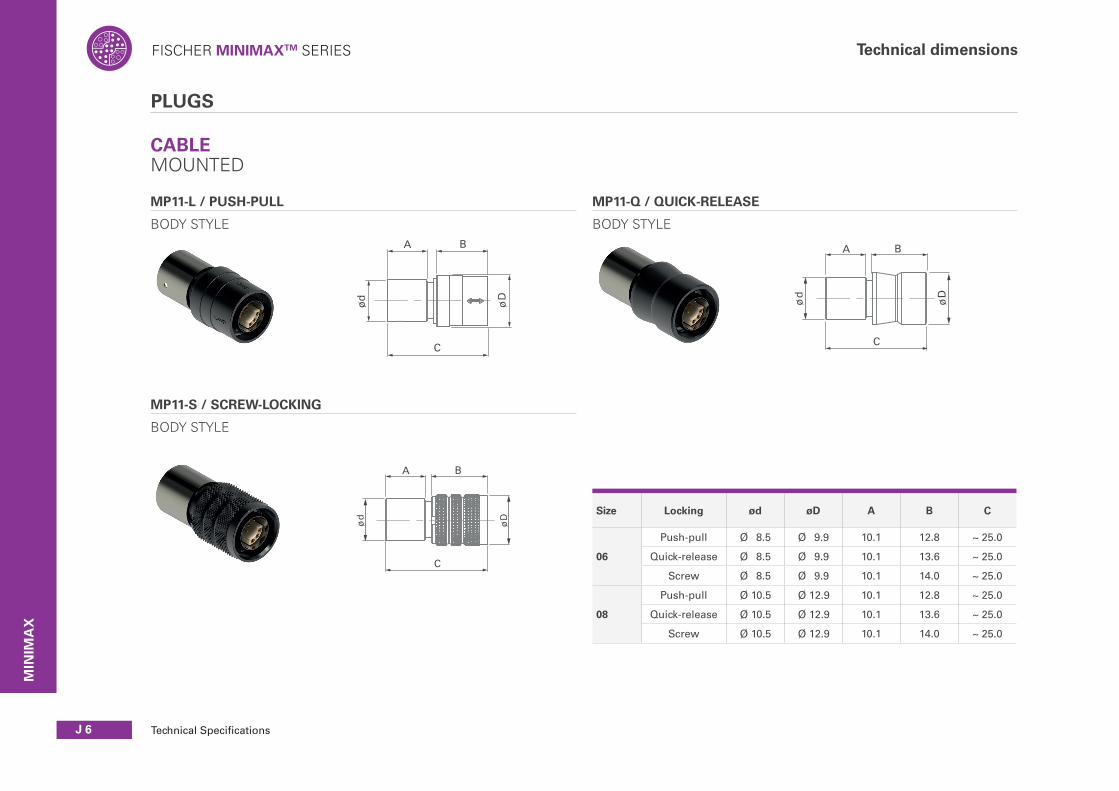
Technical dimensions
PLUGS
CABLE MOUNTED
MP11-L / PUSH-PULL
BODY STYLE
ød øD
C
A B
Push-pull version
øD
ød
Screw-lock version
C
A B
øD
ød
Quick-release version
C
A B
MP11-Q / QUICK-RELEASE
BODY STYLE
MP11-S / SCREW-LOCKING
BODY STYLE
Size Locking ød øD A B C
06
Push-pull Ø 8.5 Ø 9.9 10.1 12.8 ~ 25.0
Quick-release Ø 8.5 Ø 9.9 10.1 13.6 ~ 25.0
Screw Ø 8.5 Ø 9.9 10.1 14.0 ~ 25.0
08
Push-pull Ø 10.5 Ø 12.9 10.1 12.8 ~ 25.0
Quick-release Ø 10.5 Ø 12.9 10.1 13.6 ~ 25.0
Screw Ø 10.5 Ø 12.9 10.1 14.0 ~ 25.0
MIN
IMA
X

FISCHER MINIMAXTM SERIES
J 7All dimensions and images shown are in millimeters and are for reference only.
Technical dimensions
CABLE MOUNTED
MP11-L/S/Q
STRAIGHT OVERMOLDING
DIMENSIONS OF OVERMOLDING (AVAILABLE ON REQUEST)
MP11-L/S/Q
RIGHT-ANGLE OVERMOLDING
øD
B
ød max.
A
Push-pull version with right-angle overmolding
Aø
D
ød
max
.
Push-pull version with straight overmolding
Size Angle ød øD A B
06Straight Ø 4.7 Ø 10.8 30 -
90° Ø 4.7 Ø 10.8 23 30
08Straight Ø 6.7 Ø 12.8 30 -
90° Ø 6.7 Ø 12.8 23 30
MIN
IMA
X

FISCHER MINIMAXTM SERIES
Technical SpecificationsJ 8
Technical dimensions
RECEPTACLES
CABLE MOUNTED
MR50-L / PUSH-PULL
BODY STYLE
øD
ød
C
A B
M
ød
øD
C
A B
MR50-Q / QUICK-RELEASE
BODY STYLE
MR50-S / SCREW-LOCKING
BODY STYLE
ød
øD
C
A B
Size Locking ød øD A B C M
06
Push-pull Ø 8.5 Ø 9.9 10.1 13.7 ~ 25.0 -
Quick-release Ø 8.5 Ø 9.9 10.1 13.7 ~ 25.0 -
Screw Ø 8.5 Ø 9.9 10.1 13.7 ~ 25.0 M8x2
08
Push-pull Ø 10.5 Ø 11.6 10.1 13.7 ~ 25.0 -
Quick-release Ø 10.5 Ø 12.9 10.1 13.7 ~ 25.0 -
Screw Ø 10.5 Ø 12.9 10.1 13.7 ~ 25.0 M10x2
MIN
IMA
X

FISCHER MINIMAXTM SERIES
J 9All dimensions and images shown are in millimeters and are for reference only.
Technical dimensions
RECEPTACLES
PANEL REAR MOUNTED
MR11-L / PUSH-PULL
BODY STYLE
MR11-Q / QUICK-RELEASE
BODY STYLE
L
A
B
Quick-release PCB version
L
A
B
L
Push-pull solder version
øD ød M
Flat
A Panel: Max
Quick-release solder version
ø døD M
L
Panel: MaxA
Flat
SOLDER
PCB
SOLDER
PCB
Size Locking Termination ød øD A B LPanelmax.
MPanel thread
Torque
06
Push-pullSolder Ø 8.0 Ø 10.0 7.6 - 19.1 3.0 M8.5x0.35 8 1.0Nm
PCB Ø 8.0 Ø 10.0 7.3 4.7 18.8 3.0 M8.5x0.35 8 1.0Nm
Quick-release
Solder Ø 7.8 Ø 10.0 7.6 - 19.1 3.0 M8.5x0.35 8 1.0Nm
PCB Ø 7.8 Ø 10.0 7.3 4.7 18.8 3.0 M8.5x0.35 8 1.0Nm
08
Push-pullSolder Ø 10.0 Ø 12.0 9.1 - 20.6 3.0 M10.5x0.5 10 1.5Nm
PCB Ø 10.0 Ø 12.0 7.3 4.7 18.8 3.0 M10.5x0.5 10 1.5Nm
Quick-release
Solder Ø 9.8 Ø 12.0 9.1 - 20.6 3.0 M10.5x0.5 10 1.5Nm
PCB Ø 9.8 Ø 12.0 7.3 4.7 18.8 3.0 M10.5x0.5 10 1.5Nm
Size X Y
06 Ø 8.58+0.1/0 8.25+0.1/0
08 Ø 10.45+0.1/0 10.2+0.1/0
MIN
IMA
X
PANEL CUT-OUT
X
Y
Panel cut-out Top

FISCHER MINIMAXTM SERIES
Technical SpecificationsJ 10
Technical dimensions
Screw-lock PCB version
L
A
B
Screw-lock solder version
M2
øD M1
ød
L
Panel: MaxA
Flat
SOLDER
PCB
RECEPTACLES
PANEL REAR MOUNTED
MR11-S / SCREW-LOCKING
BODY STYLE
Size Locking Termination ød øD A B LPanel Max
M1Panel thread
M2Lockingthread
Torque
06 ScrewSolder Ø 8.0 Ø 10.0 7.6 N/A 19.1 2.3 M8.5x0.35 M8x2 8 1.0Nm
PCB Ø 8.0 Ø 10.0 7.3 4.7 18.8 2.3 M8.5x0.35 M8x2 8 1.0Nm
08 ScrewSolder Ø10.4 Ø 12.0 9.1 20.6 2.3 M10.5x0.5 M10x2 10 1.5Nm
PCB Ø10.4 Ø 12.0 7.3 4.7 18.8 2.3 M10.5x0.5 M10x2 10 1.5Nm
Size X Y
06 Ø 8.58+0.1/0 8.25+0.1/0
08 Ø 10.45+0.1/0 10.2+0.1/0
PANEL CUT-OUT
X
Y
Panel cut-out Top
MIN
IMA
X

FISCHER MINIMAXTM SERIES
J 11All dimensions and images shown are in millimeters and are for reference only.
PCB hole layout
062+2 contacts 12 contacts
ø3.1
4
ø2.3
ø0.8
ø0.55
ø0.85
4
3
2
1
ø0.8
ø0.55
4
1.70.7
0.90.4
0.9
0.4
1.65
1.65
1.55
1.55
0.6
0.6
4
327
6
98
12
11
10
15
View from the back of the plug/front of receptacle (Guide mark at 12 o’clock)
2+2 12 19 24
Power 2 ; 4 5 ; 9 9; 12; 15; 18
1)
14; 17; 20; 23
Ethernet - 1/6; 3/10; 7/8;
11/121)
8/19;10/11; 13/14; 16/17
1)
15/16; 18/19;21/22; 13/24
1)
Advanced pin
2 ; 4 - 13;192)
18;242)
1) Recommended2) Optional on MR11
08
9 contacts 19 contacts 24 contacts
5
ø0.8
ø0.55
ø5.
2
ø1.
4 15 1 432
7
6
5
17
16
14
98
13
12
11
10
1820
23
19
22
21
24
45°
2.651.650.7
2.65
1.65 0.7
3x90°ø5.35
ø2.6
ø0.8
58°
ø0.55
5
29°
29°
58°29°
15.5° 15.5° 29°
58°29
°29°58°
32° 32°
29° 29°15.5°15.5°
43
2 7
6
1918
17
16
1514
9
8
1312
11
101
5
5
60 ˜
ø5
ø0.55 ø4.6
ø1.7
ø0.8
120̃
2
1
(1)
2
4 9
(1)
3
28
6 7
5
Recommended wiring
49
8
67
513
2
1) USB2.0 D-2) SS drain3) USB2.0 D+4) Vbus 5V5) SS Tx+
6) SS Tx-7) SS Rx+8) SS Rx-9) Vbus GND
All contacts are male or female depending on polarity.
Contacts
Plugs Receptacles
Male Female
Female Male MIN
IMA
X

FISCHER MINIMAXTM SERIES
Technical SpecificationsJ 12
Part numbering
Contact termination
MP11, MR50■ S = Solder contact
MR11■ P = PCB contact■ S = Solder contact
Example: MP11 Z L 08 0420 BK 1 Z 1 A S
MR11 W S 08 2017 BK 2 E 1 A P
MR50 Z Q 08 0019 BK 4 E 1 A S
Connector design Contact block Housing Standard options
Sealing level
MP11, MR50■ Z = not applicable
MR11■ W = water sealing
Locking system
MiniMax plug & receptacle■ L = Push-pull locking■ Q = Quick-release■ S = Screw-locking
Connector size
■ 06 = Size 6■ 08 = Size 8
Number of contacts
■ Digit 1 = Advanced contacts (if applicable)■ Digit 2 = Power contacts (if physically larger compared to the other contacts)■ Digit 3+4 = Remaining contacts
Body style
MiniMax plug = MP■ MP11 = Cable mounted
MiniMax receptacle = MR■ MR11 = Panel mounted■ MR50 = Cable mounted
Contact bloc
■ A = Hermaphroditic (both MR and MP need to be “A”)■ F* = Female contacts■ M* = Male contacts
* only for size 06 configuration 0202(if MR = “F” then MP = “M”; if MR = “M” then MP = “F”)
Insulating material
■ 1 = PEEK
O-ring material
MP11■ Z = Not applicable
MR11, MR50■ E = EPDM
Keying code
■ 1 = Code 1 (insulator= Beige)■ 2 = Code 2 (insulator= Black)■ 3 = Code 3 (insulator= Beige)■ 4 = Code 4 (insulator= Black)
Housing color
■ BK = Black (standard)■ AN = Anthracite (on request)
Availablestandard options:
04202418 (MR11)
00192017 (MR11)
02100202
2007 (MP11 USB 3.0)
0009 (MR11 USB 3.0)
MIN
IMA
X

FISCHER MINIMAXTM SERIES
J 13
Accessories
All dimensions and images shown are in millimeters and are for reference only.
1) Crimp ferrule and heat shrink tube are included.
1) Crimp ferrule and heat shrink tube are included.
Size Designation ImagesPush-pull
Quick-release
Screw-lock
A øD L Part number
06 MP11 1)
• 9.6 10.0 200 MCP06C 1B2 A200 AA
• • 7.8 10.0 200 MCP06C 1B2 A200 BA
08 MP11 1)
• 9.6 12.3 200 MCP08C 1B2 A200 AA
• • 7.8 12.3 200 MCP08C 1B2 A200 BA
ø1
A
L øD
SOFT CAPS
CABLE MOUNTED
06 MR50 1) • • • 9.0 10.0 200 MCR06C 1B2 A200 AA
08 MR50 1) • • • 9.0 12.3 200 MCR08C 1B2 A200 AA
ø1
A
L øD
MIN
IMA
X

FISCHER MINIMAXTM SERIES
Technical SpecificationsJ 14
Accessories
1) Crimp ferrule, heat shrink tube and mounting ring are included.
06 MR11 1) • • • 9 10 95 MCR06P 1B2 A095 AA
08 MR11 1) • • • 9.0 12.3 95 MCR08P 1B2 A095 AA
L øD
A
ø1
0.5
ø11
.9
ø10
.5
SOFT CAPS
PANEL MOUNTED
BEND RELIEF
Size Uncut Level 1 Level 2 Part Number
06 ø2.9 ø3.9 ø5.7 MB06 A1BK
08 ø3.9 ø5.4 ø6.7 MB08 A1BK
CutCutU
ncu
t
Leve
l 1
Leve
l 2
40.5
CUTTING DIAMETERS
MIN
IMA
X

FISCHER MINIMAXTM SERIES
J 15All dimensions and images shown are in millimeters and are for reference only.
Tooling
Size Part
number Opening
across flatsLength
Fork thickness
06 TX00.008 8 96 2.3
08 TX00.010 10 104 2.5
Material – Chrome Alloy Steel, Chrome plated, Fork Angles – 15° and 75°.
SPANNER & NUT DRIVER
DOUBLE-END OPEN SPANNER EXTRA THIN
Part number
Thread sizeNut outer
dia.ø D
Hex drive
TX00.383 M8.5x0.35 10 14 7
TC00.007 M10.5 x 0.5 13 16 7
Material – Hardened Tool Steel, Nickel plated.
NUT DRIVER WITH T-HANDLE AND HEX DRIVE
øD
CABLE ASSEMBLY TOOLING
Part number Description
130257 Hand press Vogt 4255 or equivalent
Part number Description
130252 MiniMax tool kit Size 06
130253 MiniMax tool kit Size 08
Part number
Thread sizeNut outer
dia.ø D
Hex drive
TX00.386 M8.5x0.35 10 14 12
TX00.385 M10.5 x 0.5 13 16 12
Material – Hardened Tool Steel, Nickel plated and plastic.
SINGLE SIDED HEX NUT DRIVER
Part number Description
130254 MiniMax support tool
MIN
IMA
X

FISCHER MINIMAXTM SERIES
Technical SpecificationsJ 16
Technical information
Characteristic Performance Standard
Sealing performance mated and unmated
IP68; 2m submersion for 24 hours IEC 60529
Sealing performance Soft Cap IP67; 15cm submersion for 30 min IEC 60529
Operating temperature range (with PUR cable)
-40°C to +85°C IEC 60512-6-1IEC 60068-2-14-Nb
Corrosion resistance mated Salt mist 1,000 hours ; 5% salt solution, 35°CPlug and receptacle in mated position or with cap when unmated. Cosmetic changes may appear over time without impacting mechanical or electrical functions.
IEC 61300-2-1
Endurance5,000 mating cyclesPreserved mechanical and electrical functionality. Normal wear will appear.
IEC 60512-5-1 IEC 60512-5-2
Vibration (Screw-lock version only)
10 to 2000 Hz, 1.5 mm or 15g, 12 sweep cycles per axis, 20 minutes per 10-2000-10 Hz sweep cycle, no discontinuity >1µs
MIL-STD-202 G Method 204D Condition B
Unlocking Force (Quick-release version only)
Size 06 = Typical 25N±40%Size 08 = Typical 35N±40%
Shock 300 g MIL-STD-202 G Method 213
Characteristic Performance Standard
Contact resistance 5 mΩ (typical value) IEC 60512-2-1-2a; IEC 60512-2-2-2b
Shell resistance 1) <50 mΩ (Cabled) IEC 60512-2-6-2f
Insulation resistance >1010 Ω IEC 60512-3-1-3a
Shielding effectiveness 360° shielded -1) Measured for a mated pair of panel receptacle and cable plug between the grouding pin and the cable shielding.
ENVIRONMENTAL & MECHANICAL DATA
ELECTRICAL DATA
MIN
IMA
X

FISCHER MINIMAXTM SERIES
J 17
Technical information
All dimensions and images shown are in millimeters and are for reference only.
Metal PartsMaterial Finish
Designation ISO Standard Designation Standard
Housing, NutBrassCuZn39Pb3
CW614NUNS C 38500
Chrome over Nickel SAE-AMS2460
Back nut (MP11, MR50)BrassCuZn39Pb3
CW614NUNS C 38500
Nickel SAE-AMS-QQ-N-290BSAE-AMS2404G
Ground contactBrassCuZn39Pb3
CW614NUNS C 38500
Nickel SAE-AMS-QQ-N-290BSAE-AMS2404G
Push-pull locking springQuick-release locking spring
Stainless steel X10CrNi18-8 (1.4310) - -
Contacts- Male, Ground Pin
- Female
BrassCuZn39Pb3BronzeCuSn4Zn4Pb4
CW614N; UNS C 38500
CW456K; ASTM B139UNS C 54400
1µm Gold over Nickel MIL-DTL-45204DType I; ASTM B488MIL-DTL-45204DType I; ASTM B488
Ball-lockingCeramicSi3N4
- - -
Insulator and sealing International symbol Flammability
Insulators PEEK1) UL 94 V-0
O-rings- General- Interface
FPM (Viton®)EPDM
-
Sealant materials- Cable connectors- Panel receptacles
Bi-component epoxySilicone
-
Cap- Cable connectors- Panel receptacles
TPV (Santoprene) UL 94 HB
MATERIAL & SURFACE TREATMENTS
1) Or any material in the PAEK family that provides equal or better overall performances.
MIN
IMA
X

FISCHER MINIMAXTM SERIES
Technical SpecificationsJ 18
Technical information
ProtocolNumber of contacts
requiredMINIMAX
USB 2.0 4 yes
USB 3.0 9 yes
Ethernet Cat 5e (1Gb/s) 8 yes
Ethernet Cat 6a (10Gb/s) 8 yes
19 yes
It is important to note that the connector is only a small part of the equation when talking about data transmission performances. The cable quality, the cabling process and the cable length are other, more critical factors that will directly influence the performances of the cable assembly.
The data transmission performance of the Fischer MiniMax™ Series has been tested for most popular protocols that are used in a variety of applications today.
TM
DATA TRANSMISSION
MIN
IMA
X

FISCHER MINIMAXTM SERIES
J 19
MIN
IMA
X


![[Ajedrez][chess]fischer, bobby bobby fischer enseña ajedrez](https://static.fdocuments.net/doc/165x107/558e863a1a28abf16d8b475e/ajedrezchessfischer-bobby-bobby-fischer-ensena-ajedrez.jpg)