
Minimal width of foundation (bmin Principal layers
6
pm: 90 1,50 1,20 pm: 90 1,50 1,20 30 10 9,90 3,14 3,14 3,20 3,20 3,14 3,14 9,90 6,10 1,80 4,45 4,45 building order building order Calculation of the foundation Grouping the walls: loadbearing walls: 1, 3, 5, 7, 9, 11, 13, 14 non loadbearing walls: 2, 4, 6, 8, 10, 12 heavy partition walls: 15 others: 16 Specific loads to 1 m -> 12+7+3,5+25,12= 47,62 kN/m -> 12+7+13,35= 32,35 kN/m -> 7+9,60= 16,60 kN/m -> 0 kN/m -> 7+9,60= 16,60 kN/m -> 7+13,35= 20,35 kN/m -> 7+3,5+25,12= 35,62 kN/m -> 7+13,35= 20,35 kN/m -> 7+7,20= 14,20 kN/m -> 7 kN/m -> 12+7+25,12= 37,82 kN/m -> 12+7+13,35= 32,35 kN/m -> 12+7+25,12+25,6 = 69,72 kN/m -> 7+25,12+25,6= 57,72 kN/m -> 0+25,12+7,20= 32,32 kN/m -> 7 kN/m -> 0 Foundation units with the same load 00 cm: 4, 16 05 cm: 10, 15 10 cm: 3, 5, 9, 15 cm: 6, 8 20 cm: 2, 7, 11, 12, 14b 25 cm: 1 30 cm: 14a 35 cm: 13 b min 0 cm 5 cm 10 cm 15 cm 20 cm 25 cm 30 cm 35 cm b design 50 cm 50 cm 60 cm 60 cm 75 cm Foundation units with the same wall layers 40 cm:3,4,5,6,8,9,10, min. 50: 16 50 cm: 1,2,11,12,14a,14b 58 cm: 7 63 cm: 13 Width of foundation strips (theoretical) (a) -> 0,2381 m -> 25 cm -> 0,1618 m -> 20 cm -> 0,083 m -> 10 cm -> 0 -> 0 cm -> 0,083 m -> 10 cm -> 0,1018 m -> 15 cm -> 0,1781 m -> 20 cm -> 0,1018 m -> 15 cm -> 0,071 m -> 10 cm -> 0,035 m -> 5 cm -> 0,1891 m -> 20 cm -> 0,1618 m -> 20 cm -> 0,3486 m -> 35 cm -> 0,2886 m -> 30 cm -> 0,1616 m -> 20 cm -> 0,035 m -> 5 cm -> 0 -> 0 cm Main steps of foundation desing 1. Design of the layers (decisions: waterproofing level, loadbearing structure of the basement) 2. Determining the width of the foundation strips (total thickness of the superstructure + overlappings of the waterproofing + 2*5 cm tolerance) 3. Determining the depth of the foundation strips (loadbearing soil -10 cm, at least 50 cm, geometry, frost level, neighbouring building, subsoil water) 4. Designing the individual situations (level change/steps of the foundation (max. 30 degree), level next to a neighbouring building) Layout sketches S=1:200 Loading schemes Principal layers protection waterproofing basement wall internal plaster W1 - general basement wall supporting wall for the waterproofing base plaster (smoothing) waterproofing backfill mortar basement wall internal plaster W2a - basement wall at level difference Basement wall Aboveground walls thin base plaster and render system thermal insulation airtight base plaster walling internal plaster W3 - General wall adjoining level thin base plaster and render system thermal insulation (XPS) waterproofing 30 cm over the adjoining level base plaster walling internal plaster F4 - Hőszigetelt lábazat Floor layers floor covering (f.i. gres tiles) adhesive screed technological foil thermal insulation waterproofing RC screed gravel bed subsoil F1 - Floor with thermal insulation floor covering (f.i. gres tiles) adhesive screed technological foil waterproofing RC screed gravel bed subsoil F2 - Floor without thermal insulation protection dimpled plastic sheet protecting wall XPS thermal insulation protecting wall for the waterproofing backfill mortar waterproofing base plaster (smoothing) basement wall internal plaster W2b - basement wall at level difference Loads: floor slab 8 kN/m 2 / storey roof 3 kN/m 2 wall (aereated concrete) 7 kN/m/storey wall (concrete wall) 12 kN/m/storey Basic data there is only one floor + basement (partly) σ SL = 200 kN/m 2 σ = F / A Calculation of the loads to 1 meter: Similar floor slab zones: 1. 3,14 m : A, B, H, G, K -> 3,14x8=25,12 kN/m 2. 3,20 m : C, D, E, F -> 3,20x8=25,6 kN/m 3. 90 cm : I, J -> 0,90x8=7,20 kN/m Roofs: 4,45x3= 13,35 kN/m ; 3,20x3=9,60 kN/m Loads of the foundation (listed, grouped) 1: basement wall, groundfloor wall, verge walls, floor slab zone A 2: basement wall, groundfloor wall, roof 3: GF wall, roof, floor slab zone E 4: - (doors, windows) 5: groundfloor wall, roof, floor slab zone F 6: groundfloor wall, roof 7: groundfloor wall, fire wall, floor slab zone G 8: groundfloor wall, roof 9: groundfloor wall, floor slab zone J 10: groundfloor wall 11: BM + GF wall, floor slab zone K 12: basement wall, groundfloor wall (pier), roof 13: BM + GF wall, floor slab zone B+C 14a: groundfloor wall, floor slab zone H1+D 14b: - (beam), floor slab zone H2+I 15: groundfloor wall 16: - (piers) 2,00 8,00 6,10 1 2 3 4 5 6 7 8 9 10 11 12 13 14a 15 16 A 16 14b B C D E F G H 1 I J K H 2 Auxiliary structures 16 x 18 = 2,85 1 2 3 4 5 6 7 8 9 10 11 12 13 14 15 16 H 2,10 90 2,10 75 2,10 90 2,10 90 2,10 90 2,10 90 2,10 90 2,10 75 2,10 90 2,10 75 2,10 90 2,10 90 2,40 1,00 pm: 0,00 2,40 1,50 pm: 90 1,50 1,20 pm: 1,00 1,50 1,20 pm: 90 1,50 1,20 pm: 90 1,50 1,20 pm: 0,00 2,40 3,00 pm: 0,00 2,40 3,20 pm: 0,00 2,40 3,20 pm: 90 1,50 1,20 pm: 90 1,50 1,20 pm: 0,00 2,40 1,00 pm: 90 1,50 1,20 pm: 1,80 60 60 pm: 90 1,50 1,20 pm: 90 1,50 1,20 É 20,14 30 9,40 30 10,14 10,50 6,20 30 9,90 30 7,00 15 7,00 15 15 6,42 15 7,00 15 6,42 15 Property line Ground Floor S=1:200 pm: 1,80 60 60 16 x 18 = 2,85 1 2 3 4 5 6 7 8 9 10 11 12 13 14 15 16 2,10 90 2,10 90 30 9,90 30 10,50 6,20 20,14 10,14 30 9,40 30 7,00 6,57 7,00 6,57 Storage Storage - unheated cellar F2 F1 Terrace No basement Adjoining building No basement Buttress Storage Basement S=1:200 pm: 1,80 60 60 pm: 1,80 60 60 pm: 1,80 60 60 1 5 30 1 5 63 10 30 3 15 5 40 30 10 10 30 3 15 58 50 10 30 10 1 5 30 1 5 8 5 1 13 6 7 Minimal width of foundation (b min ) external basement wall Intermediate loadbearing wall with supporting wall for the waterproofing External wall (there is no basement) Next to a neighbouring building BME Faculty of Architecture Department of Building Constructions BUILDING CONSTRUCTIONS 2. 08-11-2019 1 3 WE IV. BASIC DESIGN RULES FOR FOUNDATION FOUNDATION DESIGN AND WATERPROOFING
Transcript of Minimal width of foundation (bmin Principal layers

pm: 901,501,20
pm: 901,50
1,20
3010
9,90
3,14
3,14
3,20
3,20
3,14
3,149,90
6,10
1,80
4,45 4,45
building order
building orderCalculation of the foundation
Grouping the walls:loadbearing walls: 1, 3, 5, 7, 9, 11, 13, 14non loadbearing walls: 2, 4, 6, 8, 10, 12heavy partition walls: 15others: 16
Specific loads to 1 m-> 12+7+3,5+25,12= 47,62 kN/m-> 12+7+13,35= 32,35 kN/m-> 7+9,60= 16,60 kN/m-> 0 kN/m-> 7+9,60= 16,60 kN/m-> 7+13,35= 20,35 kN/m-> 7+3,5+25,12= 35,62 kN/m-> 7+13,35= 20,35 kN/m-> 7+7,20= 14,20 kN/m-> 7 kN/m-> 12+7+25,12= 37,82 kN/m-> 12+7+13,35= 32,35 kN/m-> 12+7+25,12+25,6 = 69,72 kN/m-> 7+25,12+25,6= 57,72 kN/m-> 0+25,12+7,20= 32,32 kN/m-> 7 kN/m-> 0
Foundation units with thesame load00 cm: 4, 1605 cm: 10, 1510 cm: 3, 5, 9,15 cm: 6, 820 cm: 2, 7, 11, 12, 14b25 cm: 130 cm: 14a35 cm: 13
bmin0 cm5 cm10 cm15 cm20 cm25 cm30 cm35 cm
bdesign50 cm50 cm60 cm60 cm75 cm
Foundation units with thesame wall layers40 cm:3,4,5,6,8,9,10,min. 50: 1650 cm: 1,2,11,12,14a,14b58 cm: 763 cm: 13
Width of foundationstrips (theoretical) (a)-> 0,2381 m -> 25 cm-> 0,1618 m -> 20 cm-> 0,083 m -> 10 cm-> 0 -> 0 cm-> 0,083 m -> 10 cm-> 0,1018 m -> 15 cm-> 0,1781 m -> 20 cm-> 0,1018 m -> 15 cm-> 0,071 m -> 10 cm-> 0,035 m -> 5 cm-> 0,1891 m -> 20 cm-> 0,1618 m -> 20 cm-> 0,3486 m -> 35 cm-> 0,2886 m -> 30 cm-> 0,1616 m -> 20 cm-> 0,035 m -> 5 cm-> 0 -> 0 cm
Main steps of foundation desing1. Design of the layers (decisions: waterproofing level, loadbearing structureof the basement)
2. Determining the width of the foundation strips (total thickness of thesuperstructure + overlappings of the waterproofing + 2*5 cm tolerance)
3. Determining the depth of the foundation strips (loadbearing soil -10 cm, atleast 50 cm, geometry, frost level, neighbouring building, subsoil water)
4. Designing the individual situations (level change/steps of the foundation(max. 30 degree), level next to a neighbouring building)
Layout sketches S=1:200 Loading schemes Principal layers
protectionwaterproofingbasement wallinternal plaster
W1 - general basement wall
supporting wall for the waterproofingbase plaster (smoothing)waterproofingbackfill mortarbasement wallinternal plaster
W2a - basement wall at level difference
Basement wall
Aboveground walls
thin base plaster and render systemthermal insulationairtight base plasterwallinginternal plaster
W3 - General wall
adjoining level
thin base plaster and render systemthermal insulation (XPS)waterproofing 30 cm over the adjoining levelbase plasterwallinginternal plaster
F4 - Hőszigetelt lábazat
Floor layers
floor covering (f.i. gres tiles)adhesivescreedtechnological foilthermal insulationwaterproofingRC screedgravel bedsubsoil
F1 - Floor with thermal insulation
floor covering (f.i. gres tiles)adhesivescreedtechnological foilwaterproofingRC screedgravel bedsubsoil
F2 - Floor without thermal insulation
protection
dimpled plasticsheet
protecting wall XPS thermalinsulation
protecting wall for the waterproofingbackfill mortarwaterproofingbase plaster (smoothing)basement wallinternal plaster
W2b - basement wall at level difference
Loads:floor slab 8 kN/m2 / storeyroof 3 kN/m2
wall (aereated concrete) 7 kN/m/storeywall (concrete wall) 12 kN/m/storey
Basic datathere is only one floor + basement (partly)σSL = 200 kN/m2
σ = F / ACalculation of the loads to 1 meter:Similar floor slab zones:1. 3,14 m : A, B, H, G, K -> 3,14x8=25,12 kN/m2. 3,20 m : C, D, E, F -> 3,20x8=25,6 kN/m3. 90 cm : I, J -> 0,90x8=7,20 kN/mRoofs: 4,45x3= 13,35 kN/m ; 3,20x3=9,60 kN/m
Loads of the foundation (listed, grouped)1: basement wall, groundfloor wall, verge walls,floor slab zone A2: basement wall, groundfloor wall, roof3: GF wall, roof, floor slab zone E4: - (doors, windows)5: groundfloor wall, roof, floor slab zone F6: groundfloor wall, roof7: groundfloor wall, fire wall, floor slab zone G8: groundfloor wall, roof9: groundfloor wall, floor slab zone J10: groundfloor wall11: BM + GF wall, floor slab zone K12: basement wall, groundfloor wall (pier), roof13: BM + GF wall, floor slab zone B+C14a: groundfloor wall, floor slab zone H1+D14b: - (beam), floor slab zone H2+I15: groundfloor wall16: - (piers)
2,00 8,00 6,10
1
2
3
4
5
6
7
8
9
1011
12
13
14a
15
16
A
1614b
B
CD
EF
GH1
IJ
K
H2
Auxiliary structures
16 x 18 = 2,85
1 2 3 4 5 6
7
8
9
10
111213141516
H
2,1090
2,10 75
2,1090
2,1090
2,1090
2,1090
2,10902,10
75
2,1090
2,1075
2,10
90
2,1090
2,401,00
pm: 0,00
2,401,50
pm: 901,50
1,20
pm: 1,00 1,50
1,20
pm: 901,50
1,20
pm: 90 1,50
1,20
pm: 0,00
2,403,00
pm: 0,00 2,40
3,20
pm: 0,00 2,40
3,20
pm: 901,50
1,20
pm: 901,50
1,20
pm: 0,00
2,401,00
pm: 90 1,50
1,20
pm: 1,80 60
60
pm: 901,50
1,20
pm: 901,50
1,20
É
20,1
4
309,
4030
10,1
4
10,50 6,20
30 9,90 30
7,00
157,
0015
156,
4215
7,00
156,
4215
Property line
Ground Floor S=1:200
pm: 1,80 60
60
16 x 18 = 2,85
1 2 3 4 5 6
7
8
9
10
111213141516
2,1090
2,1090
30 9,90 30
10,50 6,20
20,1
4
10,1
430
9,40
30
7,00
6,57
7,00
6,57
StorageStorage - unheated cellar
F2
F1
TerraceNo basement
Adjoining buildingNo basement
Buttress
Storage
Basement S=1:200
pm: 1,80
6060
pm: 1,80
6060
pm: 1,80
6060
15 30 15
63
10 30 3 15 5
40
30 10
10 30 3 15
58
50
10 30 10
15 30 15 85
1
13
6
7
Minimal width of foundation (bmin)external basement wall
Intermediate loadbearingwall with supporting wallfor the waterproofing
External wall (there is no basement)
Next to a neighbouring building
BME Faculty of ArchitectureDepartment of Building Constructions BUILDING CONSTRUCTIONS 2. 08-11-2019 1 3
WE IV.BASIC DESIGN RULES FOR FOUNDATIONFOUNDATION DESIGN AND WATERPROOFING

pm: 901,501,20
pm: 901,50
1,20
3010
9,90
3,14
3,14
3,20
3,20
3,14
3,149,90
6,10
1,80
4,45 4,45
building order
building orderCalculation of the foundation
Grouping the walls:loadbearing walls: 1, 3, 5, 7, 9, 11, 13, 14non loadbearing walls: 2, 4, 6, 8, 10, 12heavy partition walls: 15others: 16
Specific loads to 1 m-> 12+7+3,5+25,12= 47,62 kN/m-> 12+7+13,35= 32,35 kN/m-> 7+9,60= 16,60 kN/m-> 0 kN/m-> 7+9,60= 16,60 kN/m-> 7+13,35= 20,35 kN/m-> 7+3,5+25,12= 35,62 kN/m-> 7+13,35= 20,35 kN/m-> 7+7,20= 14,20 kN/m-> 7 kN/m-> 12+7+25,12= 37,82 kN/m-> 12+7+13,35= 32,35 kN/m-> 12+7+25,12+25,6 = 69,72 kN/m-> 7+25,12+25,6= 57,72 kN/m-> 0+25,12+7,20= 32,32 kN/m-> 7 kN/m-> 0
Foundation units with thesame load00 cm: 4, 1605 cm: 10, 1510 cm: 3, 5, 9,15 cm: 6, 820 cm: 2, 7, 11, 12, 14b25 cm: 130 cm: 14a35 cm: 13
bmin0 cm5 cm10 cm15 cm20 cm25 cm30 cm35 cm
bdesign50 cm50 cm60 cm60 cm75 cm
Foundation units with thesame wall layers40 cm:3,4,5,6,8,9,10,min. 50: 1650 cm: 1,2,11,12,14a,14b58 cm: 763 cm: 13
Width of foundationstrips (theoretical) (a)-> 0,2381 m -> 25 cm-> 0,1618 m -> 20 cm-> 0,083 m -> 10 cm-> 0 -> 0 cm-> 0,083 m -> 10 cm-> 0,1018 m -> 15 cm-> 0,1781 m -> 20 cm-> 0,1018 m -> 15 cm-> 0,071 m -> 10 cm-> 0,035 m -> 5 cm-> 0,1891 m -> 20 cm-> 0,1618 m -> 20 cm-> 0,3486 m -> 35 cm-> 0,2886 m -> 30 cm-> 0,1616 m -> 20 cm-> 0,035 m -> 5 cm-> 0 -> 0 cm
Main steps of foundation desing1. Design of the layers (decisions: waterproofing level, loadbearing structureof the basement)
2. Determining the width of the foundation strips (total thickness of thesuperstructure + overlappings of the waterproofing + 2*5 cm tolerance)
3. Determining the depth of the foundation strips (loadbearing soil -10 cm, atleast 50 cm, geometry, frost level, neighbouring building, subsoil water)
4. Designing the individual situations (level change/steps of the foundation(max. 30 degree), level next to a neighbouring building)
Layout sketches S=1:200 Loading schemes Principal layers
protectionwaterproofingbasement wallinternal plaster
W1 - general basement wall
supporting wall for the waterproofingbase plaster (smoothing)waterproofingbackfill mortarbasement wallinternal plaster
W2a - basement wall at level difference
Basement wall
Aboveground walls
thin base plaster and render systemthermal insulationairtight base plasterwallinginternal plaster
W3 - General wall
adjoining level
thin base plaster and render systemthermal insulation (XPS)waterproofing 30 cm over the adjoining levelbase plasterwallinginternal plaster
F4 - Hőszigetelt lábazat
Floor layers
floor covering (f.i. gres tiles)adhesivescreedtechnological foilthermal insulationwaterproofingRC screedgravel bedsubsoil
F1 - Floor with thermal insulation
floor covering (f.i. gres tiles)adhesivescreedtechnological foilwaterproofingRC screedgravel bedsubsoil
F2 - Floor without thermal insulation
protection
dimpled plasticsheet
protecting wall XPS thermalinsulation
protecting wall for the waterproofingbackfill mortarwaterproofingbase plaster (smoothing)basement wallinternal plaster
W2b - basement wall at level difference
Loads:floor slab 8 kN/m2 / storeyroof 3 kN/m2
wall (aereated concrete) 7 kN/m/storeywall (concrete wall) 12 kN/m/storey
Basic datathere is only one floor + basement (partly)σSL = 200 kN/m2
σ = F / ACalculation of the loads to 1 meter:Similar floor slab zones:1. 3,14 m : A, B, H, G, K -> 3,14x8=25,12 kN/m2. 3,20 m : C, D, E, F -> 3,20x8=25,6 kN/m3. 90 cm : I, J -> 0,90x8=7,20 kN/mRoofs: 4,45x3= 13,35 kN/m ; 3,20x3=9,60 kN/m
Loads of the foundation (listed, grouped)1: basement wall, groundfloor wall, verge walls,floor slab zone A2: basement wall, groundfloor wall, roof3: GF wall, roof, floor slab zone E4: - (doors, windows)5: groundfloor wall, roof, floor slab zone F6: groundfloor wall, roof7: groundfloor wall, fire wall, floor slab zone G8: groundfloor wall, roof9: groundfloor wall, floor slab zone J10: groundfloor wall11: BM + GF wall, floor slab zone K12: basement wall, groundfloor wall (pier), roof13: BM + GF wall, floor slab zone B+C14a: groundfloor wall, floor slab zone H1+D14b: - (beam), floor slab zone H2+I15: groundfloor wall16: - (piers)
2,00 8,00 6,10
1
2
3
4
5
6
7
8
9
1011
12
13
14a
15
16
A
1614b
B
CD
EF
GH1
IJ
K
H2
1
13
6
7
Minimal width of foundation (bmin)external basement wall
Intermediate loadbearingwall with supporting wallfor the waterproofing
External wall (there is no basement)
Next to a neighbouring building
Auxiliary structures
16 x 18 = 2,85
1 2 3 4 5 6
7
8
9
10
111213141516
H
2,1090
2,10 75
2,1090
2,1090
2,1090
2,1090
2,10902,10
75
2,1090
2,1075
2,10
90
2,1090
2,401,00
pm: 0,00
2,401,50
pm: 901,50
1,20
pm: 1,00 1,50
1,20
pm: 901,50
1,20
pm: 90 1,50
1,20
pm: 0,00
2,403,00
pm: 0,00 2,40
3,20
pm: 0,00 2,40
3,20
pm: 901,50
1,20
pm: 901,50
1,20
pm: 0,00
2,401,00
pm: 90 1,50
1,20
pm: 1,80 60
60
pm: 901,50
1,20
pm: 901,50
1,20
É
20,1
4
309,
4030
10,1
4
10,50 6,20
30 9,90 30
7,00
157,
0015
156,
4215
7,00
156,
4215
Ground Floor S=1:200
pm: 1,80 60
60
16 x 18 = 2,85
1 2 3 4 5 6
7
8
9
10
111213141516
2,1090
2,1090
30 9,90 30
10,50 6,20
20,1
4
10,1
430
9,40
30
7,00
6,57
7,00
6,57
F2
F1
Basement S=1:200
pm: 1,80
6060
pm: 1,80
6060
pm: 1,80
6060
StorageStorage - unheated cellar
TerraceNo basement
Adjoining buildingNo basement
Buttress
Storage
BME Faculty of ArchitectureDepartment of Building Constructions BUILDING CONSTRUCTIONS 2. 08-11-2019 1 3
WE IV.BASIC DESIGN RULES FOR FOUNDATIONFOUNDATION DESIGN AND WATERPROOFING
2020
,14
306,
2730
2,83
303,
2730
6,27
30
30 9,90 30
2010
,00
3,27
6,87
30 9,90 30
306,
4030
30 6,60 30 3,00 30
50 6060
30 5,98 2,20 30 1,42
6075
50
30 16,115 30
30 14,175 30
50 50
60
506060
-3,30
-3,20
-0,40±0,00
60 9,60 60 1,00 1,00 1,00 1,00 1,00 665 50 1,003910
1 102,
7016
2410
5010
2,70
50
603,
20
-3,80
-3,30
-3,20
-0,50
±0,00
1,00
1,09
1,00
605,
9775
1,00
1,00
9750
1,00
1,00
4860
1,00
1,00
3,97
60
303,
2730
2,83
30
-3,80
-3,30
-2,80
-2,30
-1,80-1,47
-0,02
-3,80
-3,30
-3,20
-0,50
±0,00
±0,00
-3,80
-3,30
-2,80
-2,30
-2,06
-1,56
-1,45
-1,40
±0,00
-3,80
-3,20
±0,00
-3,80
±0,00
30
3,20 6050 2,70 20 40
1530
6,40
3015
39 20 80
-0,24
-0,39
-0,39
-0,60
±0,00
-0,24
-0,24
-3,30
-3,30
-3,30
-0,24
-0,60-1,40
-3,80-3,30 -2,80 -2,30 -1,80
-1,47
-1,40
-1,40
-0,60
-0,60
-0,60-0,24
-3,30
-2,80
-2,30
-2,06
-1,56
-1,40
-1,56 -1,40
-3,80
-3,30
-1,40-1,47
-1,40
-0,60
-0,60
<30°
AA
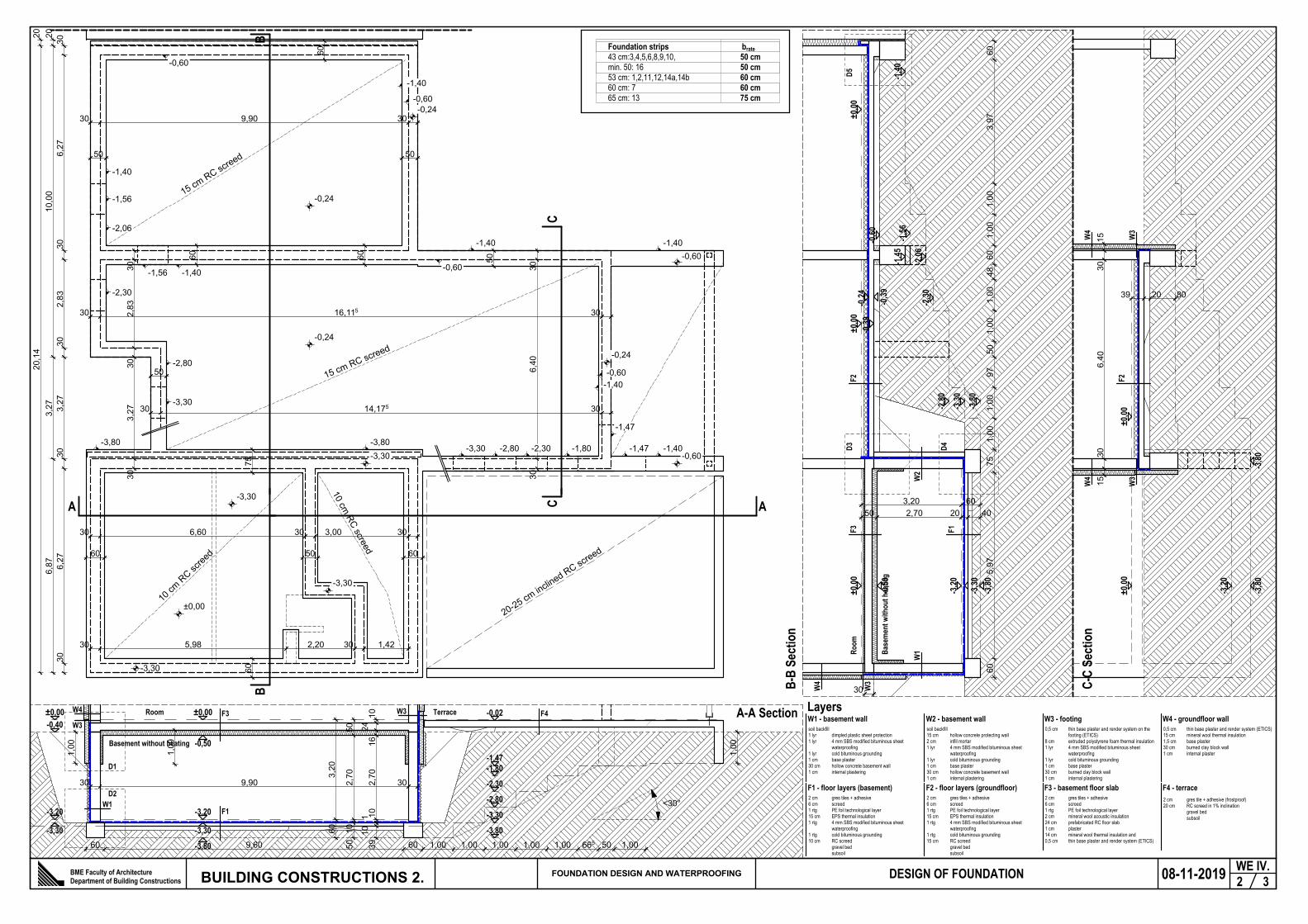
brate50 cm50 cm60 cm60 cm75 cm
Foundation strips43 cm:3,4,5,6,8,9,10,min. 50: 1653 cm: 1,2,11,12,14a,14b60 cm: 765 cm: 13
A-A Section
B-B
Sect
ion
C-C
Sect
ion
BB
CC
10 cm RC screed
10 cm
RC sc
reed
15 cm RC screed
15 cm RC screed
soil backfill1 lyr dimpled plastic sheet protection1 lyr 4 mm SBS modified bituminous sheet
waterproofing1 lyr cold bituminous grounding1 cm base plaster30 cm hollow concrete basement wall1 cm internal plastering
W1 - basement wallLayers
soil backfill15 cm hollow concrete protecting wall2 cm infill mortar1 lyr 4 mm SBS modified bituminous sheet
waterproofing1 lyr cold bituminous grounding1 cm base plaster30 cm hollow concrete basement wall1 cm internal plastering
W2 - basement wall0,5 cm thin base plaster and render system on the
footing (ETICS)8 cm extruded polystyrene foam thermal insulation1 lyr 4 mm SBS modified bituminous sheet
waterproofing1 lyr cold bituminous grounding1 cm base plaster30 cm burned clay block wall1 cm internal plastering
W3 - footing
2 cm gres tiles + adhesive6 cm screed1 rtg PE foil technological layer15 cm EPS thermal insulation1 rtg 4 mm SBS modified bituminous sheet
waterproofing1 rtg cold bituminous grounding10 cm RC screed gravel bed subsoil
F1 - floor layers (basement)2 cm gres tiles + adhesive6 cm screed1 rtg PE foil technological layer15 cm EPS thermal insulation1 rtg 4 mm SBS modified bituminous sheet
waterproofing1 rtg cold bituminous grounding15 cm RC screed gravel bed subsoil
F2 - floor layers (groundfloor)
Basement without heating
Room Terrace
Base
men
t with
out h
eatin
g
Room
2 cm gres tiles + adhesive6 cm screed1 rtg PE foil technological layer2 cm mineral wool acoustic insulation24 cm prefabricated RC floor slab1 cm plaster14 cm mineral wool thermal insulation and0,5 cm thin base plaster and render system (ETICS)
F3 - basement floor slab2 cm gres tile + adhesive (frostproof)20 cm RC screed in 1% inclination gravel bed subsoil
F4 - terrace
0,5 cm thin base plaster and render system (ETICS)15 cm mineral wool thermal insulation1,5 cm base plaster30 cm burned clay block wall1 cm internal plaster
W4 - groundfloor wall
W1
W2
W3
F1
F2
F3 F4W4 W3
W1
F1F3
F2
W3
W4
W3
W4
W3
W4
20-25 cm inclined RC screed
D1
D2
D3 D4
D5
BME Faculty of ArchitectureDepartment of Building Constructions BUILDING CONSTRUCTIONS 2. 08-11-2019 2 3
WE IV.DESIGN OF FOUNDATIONFOUNDATION DESIGN AND WATERPROOFING

2020,14
306,27
302,83
303,27
306,27
30
30 9,90 30
2010,00
3,27
6,87
30 9,90 30
306,40
3030 6,60 30 3,00 30
30 5,98 2,20 30 1,42 30
50
30 16,115 30
30 14,175 30
AA
A-A Section B-B
Sect
ion
C-C
Sect
ion
BB
CC
adjoining leveladjoining level
BME Faculty of ArchitectureDepartment of Building Constructions BUILDING CONSTRUCTIONS 2. 08-11-2019 2 3
WE III.DESIGN OF FOUNDATIONFOUNDATION DESIGN AND WATERPROOFING

1510
158
15
1515
1515
62
frost
level:
80-1
00 cm
30
3 8 3 30 15 10 15 30 4 15
0514
1524
26
216
2410
1524
1510
10
20
1,00
401
9014
7550
65 5
50
-0,50
-0,34
-0,10
±0,00
-0,50
-0,34
-0,10
±0,00
-1,40
-0,60
-0,50
-0,39
-0,24
-0,10
±0,00
-0,40
+0,01
-0,40
-0,10
±0,00
50 50
10 30 10 6 10 30 4 15 10
2515
21
15 30 15
-1,40
1,00
10
10
123
1
-3,80
-3,30
-3,20
-3,80
-3,55
-3,40
-3,30
-3,20
mechanical fastening of thethermal insulation (plug-in
anchor)
top level of the wall
mon. RC ring beam
waterproofing on the footingmin. 30 cm + mechanicalfastening and sealing on thetop
gravel bed
aluminium starting profile
corner fillet
dipmled plastic sheetwaterproofing protection
beton alaptest
2 cm mortar
1 cm PE joint strip
gres flooring and footing
1 cm PE edge strip
hollow concrete block protecting wall for thewaterproofing
infill mortar
1 course of hollow concrete blocks withbase plaster for the waterproofing 30 cmover the adjoining level
15 cm EPS thermal insulation
RC screed
overlapping of bituminous waterproofing
extruded polystyrene foam (XPS)
5 cm rockwool expansion gap
RC ring beamfilter layer
auxiliary thermal insulation(thickness of the wall x 3) cm
D1 Footing D3 D5 - Connection to the neighbouring building
D2 - Foundation under external wall D4
F1 F2
F3
F4
P1 P1
P2
P3
BME Faculty of ArchitectureDepartment of Building Constructions BUILDING CONSTRUCTIONS 2. 08-11-2019 3 3
WE IV.DETAILS S=1:10FOUNDATION DESIGN AND WATERPROOFING

D1 Footing D3 D5 - Connection to the neighbouring building
D2 - Foundation under external wall D4
BME Faculty of ArchitectureDepartment of Building Constructions BUILDING CONSTRUCTIONS 2. 08-11-2019 3 3
WE IV.DETAILS S=1:10FOUNDATION DESIGN AND WATERPROOFING


![I n d e x [] · Ringhiera | Railing | Rampe | Barandilla | Oграждение Minimal Inox 304 | Minimal Stainless steel 304 | Minimal Inox 304 | Minimal Inox 304 | Minimal нержавеющая](https://static.fdocuments.net/doc/165x107/5ff0bd63ac95b9351f4a29e6/i-n-d-e-x-ringhiera-railing-rampe-barandilla-o-minimal.jpg)
