Miniature Inertial and Augmentation Sensors for … Inertial and Augmentation Sensors ... In...
30
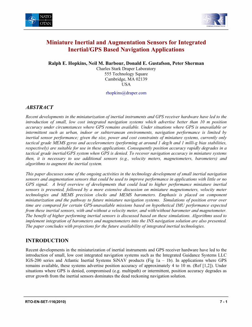
Miniature Inertial and Augmentation Sensors for Integrated Inertial/GPS Based Navigation Applications Ralph E. Hopkins, Neil M. Barbour, Donald E. Gustafson, Peter Sherman Charles Stark Draper Laboratory 555 Technology Square Cambridge, MA 02139 USA [email protected] ABSTRACT Recent developments in the miniaturization of inertial instruments and GPS receiver hardware have led to the introduction of small, low cost integrated navigation systems which advertise better than 10 m position accuracy under circumstances where GPS remains available. Under situations where GPS is unavailable or intermittent such as urban, indoor or subterranean environments, navigation performance is limited by inertial sensor performance; given the size, power and cost constraints of miniature systems, currently only tactical grade MEMS gyros and accelerometers (performing at around 1 deg/h and 1 milli-g bias stabilities, respectively) are suitable for use in these applications. Consequently position accuracy rapidly degrades in a tactical grade inertial/GPS system when GPS is denied. To recover navigation accuracy in miniature systems then, it is necessary to use additional sensors (e.g., velocity meters, magnetometers, barometers) and algorithms to augment the inertial system. This paper discusses some of the ongoing activities in the technology development of small inertial navigation sensors and augmentation sensors that could be used to improve performance in applications with little or no GPS signal. A brief overview of developments that could lead to higher performance miniature inertial sensors is presented, followed by a more extensive discussion on miniature magnetometers, velocity meter technologies and MEMS precision clocks and MEMS barometers. Emphasis is placed on component miniaturization and the pathway to future miniature navigation systems. Simulations of position error over time are compared for certain GPS-unavailable missions based on hypothetical IMU performance expected from these inertial sensors, with and without a velocity meter, and with/without barometer and magnetometer. The benefit of higher performing inertial sensors is discussed based on these simulations. Algorithms used to implement integration of barometers and magnetometers into the INS navigation solution are also presented. The paper concludes with projections for the future availability of integrated inertial technologies. INTRODUCTION Recent developments in the miniaturization of inertial instruments and GPS receiver hardware have led to the introduction of small, low cost integrated navigation systems such as the Integrated Guidance Systems LLC IGS-200 series and Atlantic Inertial Systems SiNAV products (Fig 1a – 1b). In applications where GPS remains available, these systems advertise position accuracy of approximately 4 to 10 m. (Ref [1,2]). Under situations where GPS is denied, compromised (e.g. multipath) or intermittent, position accuracy degrades as error growth from the inertial sensors dominates the dead reckoning navigation solution. RTO-EN-SET-116(2010) 7 - 1
Transcript of Miniature Inertial and Augmentation Sensors for … Inertial and Augmentation Sensors ... In...
Miniature Inertial and Augmentation Sensors for Integrated Inertial/GPS Based Navigation Applications
Ralph E. Hopkins, Neil M. Barbour, Donald E. Gustafson, Peter Sherman Charles Stark Draper Laboratory
555 Technology Square Cambridge, MA 02139
USA
ABSTRACT
Recent developments in the miniaturization of inertial instruments and GPS receiver hardware have led to the introduction of small, low cost integrated navigation systems which advertise better than 10 m position accuracy under circumstances where GPS remains available. Under situations where GPS is unavailable or intermittent such as urban, indoor or subterranean environments, navigation performance is limited by inertial sensor performance; given the size, power and cost constraints of miniature systems, currently only tactical grade MEMS gyros and accelerometers (performing at around 1 deg/h and 1 milli-g bias stabilities, respectively) are suitable for use in these applications. Consequently position accuracy rapidly degrades in a tactical grade inertial/GPS system when GPS is denied. To recover navigation accuracy in miniature systems then, it is necessary to use additional sensors (e.g., velocity meters, magnetometers, barometers) and algorithms to augment the inertial system.
This paper discusses some of the ongoing activities in the technology development of small inertial navigation sensors and augmentation sensors that could be used to improve performance in applications with little or no GPS signal. A brief overview of developments that could lead to higher performance miniature inertial sensors is presented, followed by a more extensive discussion on miniature magnetometers, velocity meter technologies and MEMS precision clocks and MEMS barometers. Emphasis is placed on component miniaturization and the pathway to future miniature navigation systems. Simulations of position error over time are compared for certain GPS-unavailable missions based on hypothetical IMU performance expected from these inertial sensors, with and without a velocity meter, and with/without barometer and magnetometer. The benefit of higher performing inertial sensors is discussed based on these simulations. Algorithms used to implement integration of barometers and magnetometers into the INS navigation solution are also presented. The paper concludes with projections for the future availability of integrated inertial technologies.
INTRODUCTION
Recent developments in the miniaturization of inertial instruments and GPS receiver hardware have led to the introduction of small, low cost integrated navigation systems such as the Integrated Guidance Systems LLC IGS-200 series and Atlantic Inertial Systems SiNAV products (Fig 1a – 1b). In applications where GPS remains available, these systems advertise position accuracy of approximately 4 to 10 m. (Ref [1,2]). Under situations where GPS is denied, compromised (e.g. multipath) or intermittent, position accuracy degrades as error growth from the inertial sensors dominates the dead reckoning navigation solution.
RTO-EN-SET-116(2010) 7 - 1
Report Documentation Page Form ApprovedOMB No. 0704-0188
Public reporting burden for the collection of information is estimated to average 1 hour per response, including the time for reviewing instructions, searching existing data sources, gathering andmaintaining the data needed, and completing and reviewing the collection of information. Send comments regarding this burden estimate or any other aspect of this collection of information,including suggestions for reducing this burden, to Washington Headquarters Services, Directorate for Information Operations and Reports, 1215 Jefferson Davis Highway, Suite 1204, ArlingtonVA 22202-4302. Respondents should be aware that notwithstanding any other provision of law, no person shall be subject to a penalty for failing to comply with a collection of information if itdoes not display a currently valid OMB control number.
1. REPORT DATE MAR 2010
2. REPORT TYPE N/A
3. DATES COVERED -
4. TITLE AND SUBTITLE Miniature Inertial and Augmentation Sensors for Integrated Inertial/GPSBased Navigation Applications
5a. CONTRACT NUMBER
5b. GRANT NUMBER
5c. PROGRAM ELEMENT NUMBER
6. AUTHOR(S) 5d. PROJECT NUMBER
5e. TASK NUMBER
5f. WORK UNIT NUMBER
7. PERFORMING ORGANIZATION NAME(S) AND ADDRESS(ES) Charles Stark Draper Laboratory 555 Technology Square Cambridge,MA 02139 USA
8. PERFORMING ORGANIZATIONREPORT NUMBER
9. SPONSORING/MONITORING AGENCY NAME(S) AND ADDRESS(ES) 10. SPONSOR/MONITOR’S ACRONYM(S)
11. SPONSOR/MONITOR’S REPORT NUMBER(S)
12. DISTRIBUTION/AVAILABILITY STATEMENT Approved for public release, distribution unlimited
13. SUPPLEMENTARY NOTES See also ADA569232. Low-Cost Navigation Sensors and Integration Technology (Capteurs de navigation afaible cout et technologie d’integration) RTO-EN-SET-116(2010)
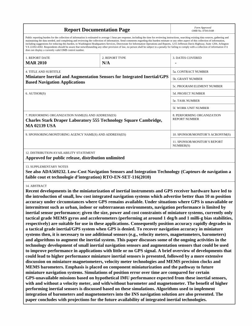
14. ABSTRACT Recent developments in the miniaturization of inertial instruments and GPS receiver hardware have led tothe introduction of small, low cost integrated navigation systems which advertise better than 10 m positionaccuracy under circumstances where GPS remains available. Under situations where GPS is unavailable orintermittent such as urban, indoor or subterranean environments, navigation performance is limited byinertial sensor performance; given the size, power and cost constraints of miniature systems, currently onlytactical grade MEMS gyros and accelerometers (performing at around 1 deg/h and 1 milli-g bias stabilities,respectively) are suitable for use in these applications. Consequently position accuracy rapidly degrades ina tactical grade inertial/GPS system when GPS is denied. To recover navigation accuracy in miniaturesystems then, it is necessary to use additional sensors (e.g., velocity meters, magnetometers, barometers)and algorithms to augment the inertial system. This paper discusses some of the ongoing activities in thetechnology development of small inertial navigation sensors and augmentation sensors that could be usedto improve performance in applications with little or no GPS signal. A brief overview of developments thatcould lead to higher performance miniature inertial sensors is presented, followed by a more extensivediscussion on miniature magnetometers, velocity meter technologies and MEMS precision clocks andMEMS barometers. Emphasis is placed on component miniaturization and the pathway to futureminiature navigation systems. Simulations of position error over time are compared for certainGPS-unavailable missions based on hypothetical IMU performance expected from these inertial sensors,with and without a velocity meter, and with/without barometer and magnetometer. The benefit of higherperforming inertial sensors is discussed based on these simulations. Algorithms used to implementintegration of barometers and magnetometers into the INS navigation solution are also presented. Thepaper concludes with projections for the future availability of integrated inertial technologies.

15. SUBJECT TERMS
16. SECURITY CLASSIFICATION OF: 17. LIMITATION OF ABSTRACT
SAR
18. NUMBEROF PAGES
28
19a. NAME OFRESPONSIBLE PERSON
a. REPORT unclassified
b. ABSTRACT unclassified
c. THIS PAGE unclassified
Standard Form 298 (Rev. 8-98) Prescribed by ANSI Std Z39-18

Miniature Inertial and Augmentation Sensors for Integrated Inertial/GPS Based Navigation Applications
Fig. 1a. IGS-200 Series Navigation System Ref [1]
Fig 1b. AIS SiNAV Navigation System Ref [2]
There are many emerging mission applications for GPS-unavailable navigators; typical missions are personal navigation in urban (indoor and outdoor) environments, search and rescue robots in difficult access (e.g., rubble) environments, autonomous land vehicle in urban or rural environments, and autonomous underwater vehicles in littoral or deep ocean environments. Typical position knowledge desired is 1 to 3 meters over periods of minutes to hours, under operational temperatures from -25 to +130 degrees F and rate and acceleration measurement ranges up to 360 deg/s and 5g. Table 1 presents a summary of several mission requirement goals for urban and subterranean/sub-ocean environments.
Table 1. Mission Requirement Goals
Mission
Goals Urban
Personal Navigation System
Subterranean Personal
Navigation System Search &
Rescue Robot Autonomous
Land Vehicle
Autonomous Undersea Vehicle
Size (in3) 10 12 4 25 25
Weight (lb) 0.5 3 1 2 2
Power (w) 5 5 1 20 20
GPS Availability Intermittent Denied Denied Intermittent Denied
Mission Time (h) No Limit 0.5 8 1 1 8
Position Knowledge (meters) 3 3 3 1 3 10
Velocity Meter Yes No Yes Yes Yes Yes
Max Speed (m/s) 1 1 1 1 10 10
Currently, miniature inertial/GPS systems feature tactical grade instruments having approximately 1 deg/h (gyro) and 1 milli-g (accelerometer) bias stabilities. Unaided, the position error from 1 milli-g of accelerometer bias uncertainty alone integrates to approximately 17 m in 1 minute, and will grow by over 3 orders of magnitude in an hour. A personal navigation application where horizontal position needs to be known to 1 meter after 1 hour in the absence of GPS would require gyro and accelerometer bias performance
7 - 2 RTO-EN-SET-116(2010)
Miniature Inertial and Augmentation Sensors for Integrated Inertial/GPS Based Navigation Applications
on the order of ~5 micro-deg/hr and ~15 nano-g, respectively. No suitable (e.g., cost, size, power) inertial technology exists today that approaches this performance level. Consequently, in a GPS-denied environment, the use of active and passive augmentation sensors (aiding devices) is required to provide velocity and/or attitude updates to bound the error due to the drift in the inertial components.
Examples of augmentation sensors are velocity sensors, odometers, baroaltimeters, magnetometers, ranging devices, proximity sensors, and GPS pseudolites. There can also be improvements from using special procedures such as ZUPTs (Zero Velocity Updates), mapping information, or path crossings. Augmentation sensors open the door to the use of much lower performing inertial sensors, so that current technology can be used.
This paper presents a brief overview of current developments in inertial sensor technology that show promise for improving performance in a miniature form factor. Timing references and augmentation sensors, namely magnetometers, barometers and velocity sensors are discussed in more detail, with emphasis placed on current miniaturization efforts. Some discussion of sensor integration algorithms is also presented, along with performance simulations of some candidate architectures.
MINIATURE INERTIAL TECHNOLOGIES
In recent years, three major technologies in inertial sensing have enabled advances in military (and commercial) capabilities: the Ring Laser Gyro (since ~1975), Fiber Optic Gyros (since ~1985), and MEMS (since ~1995). RLGs enabled many new military missions because of their superior scale factor stability and negligible g-sensitivity. FOGs have been developed as a lower cost alternative to RLGs, and are employed in similar mission and system applications as RLGs. MEMS inertial sensors are a key enabling technology for miniature inertial navigation systems. The MEMS technology created a new marketplace for inertial navigation, namely guided tactical munitions and other emerging miniature GPS-integrated applications such as personal navigators.
Extensive details of current inertial sensor state-of-the-art are discussed in ref [3]. This paper presents a brief summary of noteworthy technology developments that show promise for achieving higher performance in a miniature size than is currently available. These inertial components concepts thus have potential for insertion in future, emerging miniaturized integrated navigation systems.
Optical Gyros The Fiber Optic Gyro is a mature technology (Refs [4-6]) with performance and size comparable to the RLG. However, ongoing developments in solid-state optics and fiber technology could potentially lead to 0.001 deg/h performance in a miniature design. Specifically, the development of photonic crystal fibers (PCF) (Refs [7, 8]) and monolithic Integrated Optical Chips could lead to the development of a Miniature FOG (MFOG).
In contrast to conventional optical fibers, PCF fiber maintains superior mode confinement of the optical energy under sharp bend radius conditions, enabling the fabrication of small diameter (~ 2.5 cm) FOG sense coils. Another step in miniaturizing FOGs is the development of a miniature, monolithic optical chip which contains the source and detector as well as the modulator. However, overcoming problems of backscatter and residual intensity modulation must be resolved.
Another technology suitable for miniaturizing the FOG has been around since the early 1980s, but never perfected. This is the Resonant FOG (RFOG) which utilizes short lengths of fiber in which the cw and ccw
RTO-EN-SET-116(2010) 7 - 3
Miniature Inertial and Augmentation Sensors for Integrated Inertial/GPS Based Navigation Applications
light beams are kept in resonance. This requires a very narrow-band light source and low loss fibers. RFOGs offer the potential for equivalent IFOG performance, but with coil lengths up to 100 times shorter.
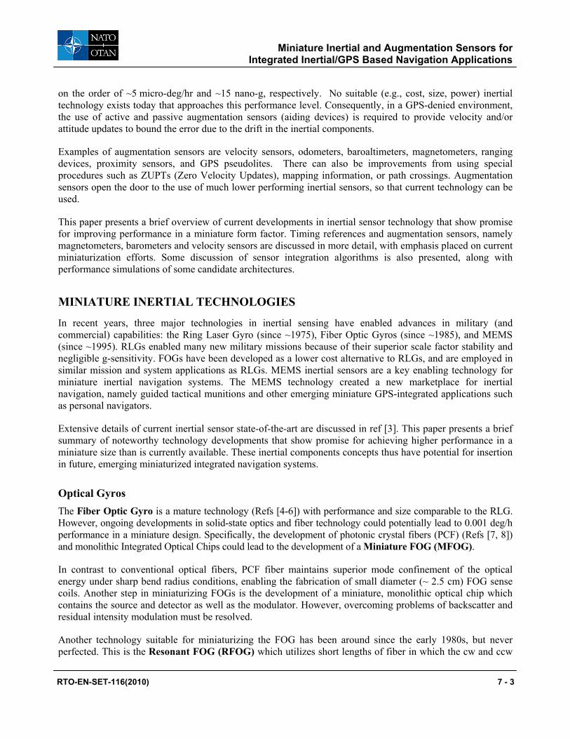
The RFOG architecture can be implemented in an Integrated Optics Gyro (or optical gyro on a chip), a tantalizing concept lurking around inertial sensor labs for several years. The IOG is an optical waveguide based Sagnac effect gyroscope in which two beams of light travel in opposite directions around a waveguide ring resonator in place of an optical fiber. The IO gyros are fabricated on wafers, combining the capabilities of integrated optic fabrication and MEMS fabrication. Figure 2 shows a schematic of an IOG with all of the components on-chip as well as a close-up of an optical waveguide.
Figure 2. Integrated Optic Gyro (IOG)
One of the keys to achieving navigation grade performance (0.01 deg/h and 0.001 deg/√h) is to be able to manufacture waveguides with losses less than 0.001 dB/cm. Current state of the art resonator waveguide losses are two orders of magnitude away [Refs 9, 10]. Efforts are also ongoing to look at the advantages of slowing light to make an ultrasensitive optical gyroscope [Refs 11, 12], but these are still at the basic research level.
MEMS MEMS inertial sensor development continues to be a world-wide effort. At present the performance of MEMS IMUs continues to be limited by gyro performance [Ref 13], which is now at around 1 deg/h, rather than by accelerometer performance, which has demonstrated tens of micro-g or better. Therefore, MEMS rate sensors and all-MEMS IMUs are restricted to commercial systems or tactical grade INS/GPS systems, and require the integration of augmentation sensors in GPS-denied environments.
Interest in obtaining higher performing MEMS gyros is strong, and there are ongoing initiatives to move beyond the traditional Coriolis Vibratory MEMS gyro [Refs 14, 15]. The DARPA BAA in 2004 for navigation grade MEMS gyros initiated development in the USA. Also, the European Space Agency (ESA) has funded several market analyses and feasibility studies [Ref 16] based on European developments of MEMS gyros, with a desired goal of 0.1 deg/h bias stability.
Reference 17 indicates that the way to get higher performance (e.g., navigation grade) devices is to perfect the rate integrating MEMS gyro; basically a free oscillating two-dimensional resonator. Data from a preliminary
7 - 4 RTO-EN-SET-116(2010)

Miniature Inertial and Augmentation Sensors for Integrated Inertial/GPS Based Navigation Applications
design is presented. In general though, it appears that production quantities of MEMS gyros with performance beyond tactical grade is still several years away.
The most accurate MEMS accelerometer is Draper Laboratory’s Silicon Oscillating Accelerometer (SOA), a resonant beam accelerometer which has demonstrated performance of 1 micro g and 1 ppm at Draper lab and under independent laboratory testing [Ref 14].
Quartz IMUs continue to show improved performance in several areas. Systron Donner’s MMQ50 series combines a quartz rate sensor with a silicon MEMS accelerometer [Ref 19]. The quartz rate sensor is based on technology developed for the automobile industry to which over 25 million have been shipped to date. Systron Donner continues to develop more accurate and robust sensors for future products. Also, ONERA (Fr) [Ref 20] continues development of the VIA (Vibrating Inertial Accelerometer) and the VIG (Vibrating Integrating Gyro). The VIA’s accuracy is currently around 300 micro g, A further reduction in size, with targeted accuracy of 100 micro g, is underway by configuring the accelerometer on one single chip rather than two.
Atom Interferometer Sensors A potentially promising technology, which is in its early development stages, is inertial sensing based upon atom interferometry (sometimes known as cold atom sensors [Ref 21]. Currently atom interferometers and proof-of-concept AI gyros and accelerometers are large, table-top sized experiments. However, miniaturization to a typical tactical-sized inertial sensor appears feasible. Figures 3a, 3b show a schematic and photo of a MEMS fabricated magneto-optic trap for manipulating Bose Einstein Condensates (BECs). As fabricated, the MEMS magneto-optical trap chip size is 1.27 cm x 1.27 cm. Reference [22] presents examples of using a magneto-optic trap to coherently split and re-combine BECs in an interferometer.
Fig. 3a. Schematic of Magneto-optic Trap Ref [22]
Fig 3b. Microfabricated magneto-optic trap Ref [22]
MINIATURE AUGMENTATION SENSORS
Among the components critical for development of a miniaturized integrated Inertial/GPS system are “augmentation” sensors such as barometers, magnetometers, velocity meters and timing references. Recent developments in MEMS and solid state optical technologies are, as is the case with inertial sensors, enabling
RTO-EN-SET-116(2010) 7 - 5
Miniature Inertial and Augmentation Sensors for Integrated Inertial/GPS Based Navigation Applications
the development of miniaturized versions of these sensors with performance suitable for integration with small INS/GPS systems. This section discusses operational principles, miniature designs and performance considerations for these sensors.
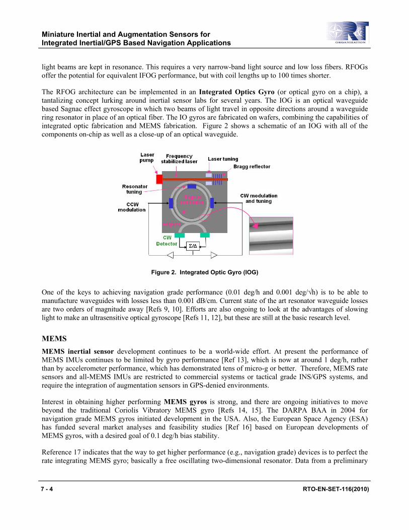
Magnetometers Magnetometers are used to augment the heading information in integrated navigation systems by furnishing orientation with respect to earth’s magnetic field. Magnetometers are available in many designs employing different technologies. Figure 4 below (adapted from ref [23]) shows the performance range of different magnetometer technologies spans approximately six orders of magnitude, starting with Hall sensors at the coarse end, to Superconducting Quantum Interference Device (SQUID) designs at the very high sensitivity end of the spectrum.
Fig 4 Magnetometer Technologies v. Performance
Because of the need to cool SQUID devices to cryogenic temperature, their application is limited to laboratory and clinical settings such as in hospital MRI imaging systems.
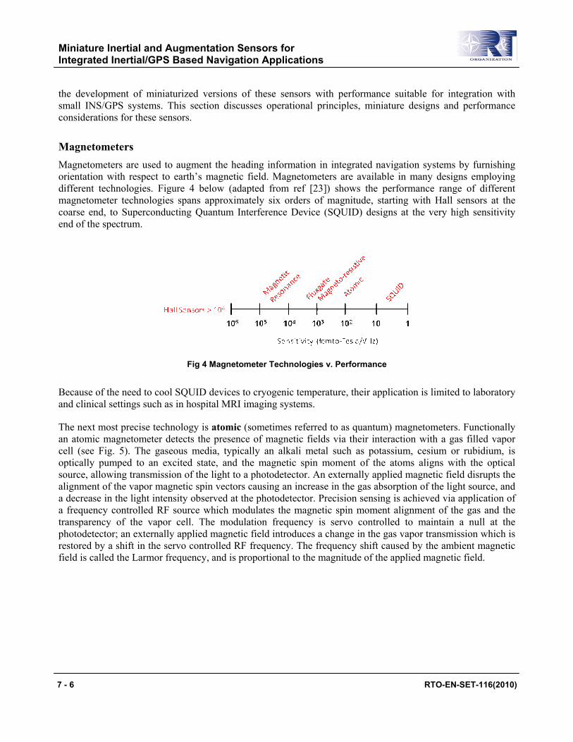
The next most precise technology is atomic (sometimes referred to as quantum) magnetometers. Functionally an atomic magnetometer detects the presence of magnetic fields via their interaction with a gas filled vapor cell (see Fig. 5). The gaseous media, typically an alkali metal such as potassium, cesium or rubidium, is optically pumped to an excited state, and the magnetic spin moment of the atoms aligns with the optical source, allowing transmission of the light to a photodetector. An externally applied magnetic field disrupts the alignment of the vapor magnetic spin vectors causing an increase in the gas absorption of the light source, and a decrease in the light intensity observed at the photodetector. Precision sensing is achieved via application of a frequency controlled RF source which modulates the magnetic spin moment alignment of the gas and the transparency of the vapor cell. The modulation frequency is servo controlled to maintain a null at the photodetector; an externally applied magnetic field introduces a change in the gas vapor transmission which is restored by a shift in the servo controlled RF frequency. The frequency shift caused by the ambient magnetic field is called the Larmor frequency, and is proportional to the magnitude of the applied magnetic field.
7 - 6 RTO-EN-SET-116(2010)
Miniature Inertial and Augmentation Sensors for Integrated Inertial/GPS Based Navigation Applications
Fig 5. Schematic of Atomic Magnetometer
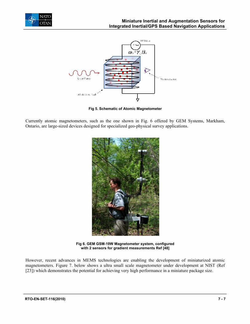
Currently atomic magnetometers, such as the one shown in Fig. 6 offered by GEM Systems, Markham, Ontario, are large-sized devices designed for specialized geo-physical survey applications.
Fig 6. GEM GSM-19W Magnetometer system, configured with 2 sensors for gradient measurements Ref [48]
However, recent advances in MEMS technologies are enabling the development of miniaturized atomic magnetometers. Figure 7. below shows a ultra small scale magnetometer under development at NIST (Ref [23]) which demonstrates the potential for achieving very high performance in a miniature package size.
RTO-EN-SET-116(2010) 7 - 7

Miniature Inertial and Augmentation Sensors for Integrated Inertial/GPS Based Navigation Applications
Fig 7. NIST Miniature Atomic Magnetometer (Ref [23])
Until miniature atomic magnetometers transition from laboratory demonstration units to a mass produced product, fluxgate and/or magnetoresistive designs are a better suited magnetometer technology for a miniature navigation system. Figure 8 below shows the basic fluxgate design concept (example ref [35]). A magnetic core material is wound with a set of drive and sense coils; application of AC current to the drive induces an alternating magnetic field that induces an AC output voltage in the sense coil, which is symmetric about zero in the absence of external magnetic fields. The application of an external magnetic field biases the AC output voltage and produces a net differential output in the magnetometer proportional to the strength of the applied field. Fluxgate designs are sensitive to magnetic fields applied along the central core axis; hence a triad is required to resolve magnetic field orientation.
Fig 8. Fluxgate Magnetometer Schematic
The PNI Sensor Corporation (Santa Rosa, CA, www.pnicorp.com) offers several models of magnetometers suitable for inertial system augmentation. For example, their TCM 5 and TCM 6 models (Fig. 9 ref [26]) are full 3-axis modules with integrated MEMS accelerometers for tilt compensation. The three-axis module design enables determination of magnetic north through simple trigonometric computations. Magnetic north heading can be converted to a true north frame by adding a declination angle from a database reference such as the World Magnetic Model (ref [27]).
Fig 9. PNI TCM 5 and TCM 6 Magnetometer Modules (Ref [26])
7 - 8 RTO-EN-SET-116(2010)
Miniature Inertial and Augmentation Sensors for Integrated Inertial/GPS Based Navigation Applications
The TCM series magnetometers are nominally a 0.1° accuracy sensor and feature a digitally enabled compensation capability to account for the magnetic field distortion of neighboring hard and soft magnetic materials. Hard magnetic materials maintain their north-south polarity with orientation; hence, compensation for hard magnetic distortion takes the form of (ref [49]):
ψψψ mymxm HH sincos +=∆ [1]
where: ψm= magnetic heading angle ∆ψm= magnetic heading error Hx, Hy = x and y axis calibration coefficients Soft magnetic materials are re-magnetized with orientation changes with respect to Earth’s field which alters the functional form of the compensation approach to (ref [49]):
ψψψ 2sin2cos mymxm SS +=∆ [2]
where: ψm= magnetic heading angle ∆ψm= magnetic heading error Sx, Sy = x and y axis calibration coefficients A pair of hard and soft iron compensation coefficients could be defined mathematically for each axis, however each of these 12 coefficients may not be independently observable.
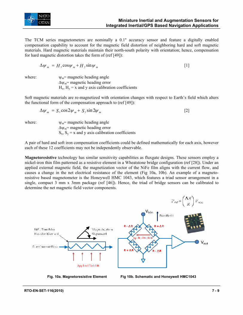
Magnetoresistive technology has similar sensitivity capabilities as fluxgate designs. These sensors employ a nickel-iron thin film patterned as a resistive element in a Wheatstone bridge configuration (ref [28]). Under an applied external magnetic field, the magnetization vector of the NiFe film aligns with the current flow, and causes a change in the net electrical resistance of the element (Fig 10a, 10b). An example of a magneto-resistive based magnetometer is the Honeywell HMC 1043, which features a triad sensor arrangement in a single, compact 3 mm x 3mm package (ref [46]). Hence, the triad of bridge sensors can be calibrated to determine the net magnetic field vector components.
Fig. 10a. Magnetoresistive Element Fig 10b. Schematic and Honeywell HMC1043
RTO-EN-SET-116(2010) 7 - 9
Miniature Inertial and Augmentation Sensors for Integrated Inertial/GPS Based Navigation Applications
Requirements on the performance of a magnetometer for use in a navigation system are driven by scaling of magnetic field strength as the sensor is rotated from magnetic north to magnetic east. In the mid-latitude area of the northern hemisphere, the scaling is about 270 nT/deg. Noise equivalent resolution of 0.1deg/√Hz requires a sensor noise floor of 27nT/√Hz, the Honeywell HMC 1043 resolution is specified at 12 nT/√Hz.
Magnetic attitude sensing for surface navigation is limited not by sensor noise but by deviations in the sensed magnetic field from models of field strength vs. location and date. With the exception of magnetic storms, the strongest anomalies affecting magnetic-aided surface navigation are field distortions from iron objects associated with human artifacts; though in instances where the distortions are from fixed hard and soft magnetic sources, these effects can be compensated as mentioned above.
More challenging is the case where magnetic distortion effects change with the users position, An example of this is shown in the plots in Figure 11 where the “true” inertial heading (red) and magnetic indicated heading (blue) are contrasted. Inertial data was taken from an IMU with tactical MEMS instruments designed and fabricated at Draper Laboratory. These instruments are developmental versions of the instruments used in the Honeywell HG1930 IMU. The top plot contains data from an open field athletic track; the middle plot depicts an Urban Canyon area, and bottom plot represents indoors in a metal frame building. The vertical scales in all three are the same, 45°/division. The progression shows increasing magnetic anomalies going from open field to indoors.
7 - 10 RTO-EN-SET-116(2010)

Miniature Inertial and Augmentation Sensors for Integrated Inertial/GPS Based Navigation Applications
0 100 200 300 400 500 600 700 800 900 1000 1100180
135
90
45
0
45
90
135
180
g
400 450 500 550 600 650 700 750 800 8500
4590
135180225270315360
2200 2400 2600 2800 3000 3200 3400 3600 3800 4000 4200 4400 46000
45
90
135
180
225
270
315
360
Hea
ding
(deg
)H
eadi
ng (d
eg)
Hea
ding
(deg
)
Time (sec)Inertial heading - redMagnetic heading - blue
MIT Track
Urban Canyon
Indoors
Fig 11. Magnetic v. Inertial Heading
This data highlights the challenges for using magnetic sensing in a dead reckoning system in discriminating valid (i.e. model following) measurements from anomalous ones. Reference [27] suggests a pre-filtering approach to rejecting local magnetic anomalies, where magnetometer readings are rejected if: 1) the magnetometer indicated heading differs from the inertial indicated heading by more than three standard deviations, or 2) if indicated magnetic flux density exceeds its average value by a certain factor.
Barometers The addition of a barometer to integrated navigation systems is not a novel idea as they are typically inserted in INS systems to constrain position error growth in the local vertical channel (Ref [29, 30, 31]). Equation [3] below shows how vertical acceleration is calculated in a local level frame:
RTO-EN-SET-116(2010) 7 - 11
Miniature Inertial and Augmentation Sensors for Integrated Inertial/GPS Based Navigation Applications
( )VVh ENNNEZSF gA ωω ++−−= Ω [3]
where: = Indicated z-axis (vertical) acceleration AZSF = Z-axis accelerometer indicated specific force g = Plumb-bob local gravity VN , VE = North and East velocities relative to earth frame ωN , ωE = North and East local frame angular rates relative to earth frame ΩN = North component of earth rate Neglecting the coriolis frame-rate terms in [3] and integrating twice gives, to first order, the estimate for vertical position (h):
( ) dtdtgAZSFh ∫∫ −= [4]
Equation [4] reveals the vertical channel instability problem; local gravity (g) is determined via a model in the INS flight computer, and is a function of altitude. A positive altitude error will cause an under estimate in the value of g, which subsequently leads to an increase in the positive altitude error. Likewise a negative altitude error causes an over estimate of g which further contributes the altitude under estimate. Consequently, in an inertial-only system, the vertical channel is inherently unstable with the altitude estimate diverging either positively or negatively with time. Gravity as a function of altitude is given by:
−=
Rh
ghg 21)( 0 [5]
where: g(h) = Plumb-bob local gravity as a function of altitude h g0 = Nominal plumb-bob local gravity (9.8 m/s2) h = Altitude R = Nominal earth radius (6.378 x 10⁶ m) From [5] then, a differential equation for altitude error can be written as (ref [31]):
02=− h
Rg
h ee [6]
where: he = altitude error Solving [6] with a non-zero position error (h0) initial condition gives the growth in altitude error estimate as:
= t
Rg
hthe0
02
cosh)( [7]
7 - 12 RTO-EN-SET-116(2010)
Miniature Inertial and Augmentation Sensors for Integrated Inertial/GPS Based Navigation Applications
Substituting numerical values into [7] shows that an initial altitude error will double after about 750 seconds unless compensated by an external sensor such as a barometer.
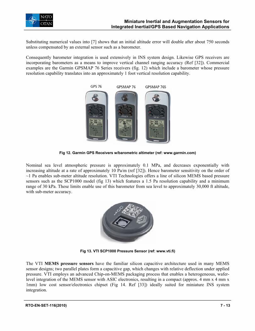
Consequently barometer integration is used extensively in INS system design. Likewise GPS receivers are incorporating barometers as a means to improve vertical channel ranging accuracy (Ref [32]). Commercial examples are the Garmin GPSMAP 76 Series receivers (fig. 12) which include a barometer whose pressure resolution capability translates into an approximately 1 foot vertical resolution capability.
Fig 12. Garmin GPS Receivers w/barometric altimeter (ref: www.garmin.com)
Nominal sea level atmospheric pressure is approximately 0.1 MPa, and decreases exponentially with increasing altitude at a rate of approximately 10 Pa/m (ref [32]). Hence barometer sensitivity on the order of ~1 Pa enables sub-meter altitude resolution. VTI Technologies offers a line of silicon MEMS based pressure sensors such as the SCP1000 model (fig 13) which features a 1.5 Pa resolution capability and a minimum range of 30 kPa. These limits enable use of this barometer from sea level to approximately 30,000 ft altitude, with sub-meter accuracy.
Fig 13. VTI SCP1000 Pressure Sensor (ref: www.vti.fi)
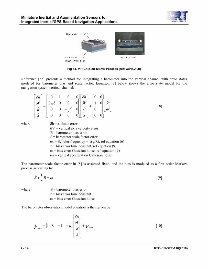
The VTI MEMS pressure sensors have the familiar silicon capacitive architecture used in many MEMS sensor designs; two parallel plates form a capacitive gap, which changes with relative deflection under applied pressure. VTI employs an advanced Chip-on-MEMS packaging process that enables a heterogeneous, wafer-level integration of the MEMS sensor with ASIC electronics, resulting in a compact (approx. 4 mm x 4 mm x 1mm) low cost sensor/electronics chipset (Fig 14. Ref [33]) ideally suited for miniature INS system integration.
RTO-EN-SET-116(2010) 7 - 13
Miniature Inertial and Augmentation Sensors for Integrated Inertial/GPS Based Navigation Applications
Fig 14. VTI Chip-on-MEMS Process (ref: www.vti.fi)
Reference [32] presents a method for integrating a barometer into the vertical channel with error states modeled for barometer bias and scale factor. Equation [8] below shows the error state model for the navigation system vertical channel:
+
−=
ωδδ
δ
τ
ωδδ
a
SBVh
SBVh
s
00100100
0000010000020010
2
[8]
where: δh = altitude error δV = vertical axis velocity error B = barometer bias error S = barometer scale factor error ωs = Schuler frequency = √(g/R), ref equation (6) τ = bias error time constant, ref equation (9) ω = bias error Gaussian noise, ref equation (9) δa = vertical acceleration Gaussian noise The barometer scale factor error in [8] is assumed fixed, and the bias is modeled as a first order Markov process according to:
ωτ
=+ BB 1 [9]
where: B = barometer bias error τ = bias error time constant ω = bias error Gaussian noise The barometer observation model equation is then given by:
[ ] νδδ
barobaro
SBVh
hy +
−−= 101 [10]
7 - 14 RTO-EN-SET-116(2010)
Miniature Inertial and Augmentation Sensors for Integrated Inertial/GPS Based Navigation Applications
where: ybaro = barometer observation model output νbaro = barometer noise h = vertical altitude estimate
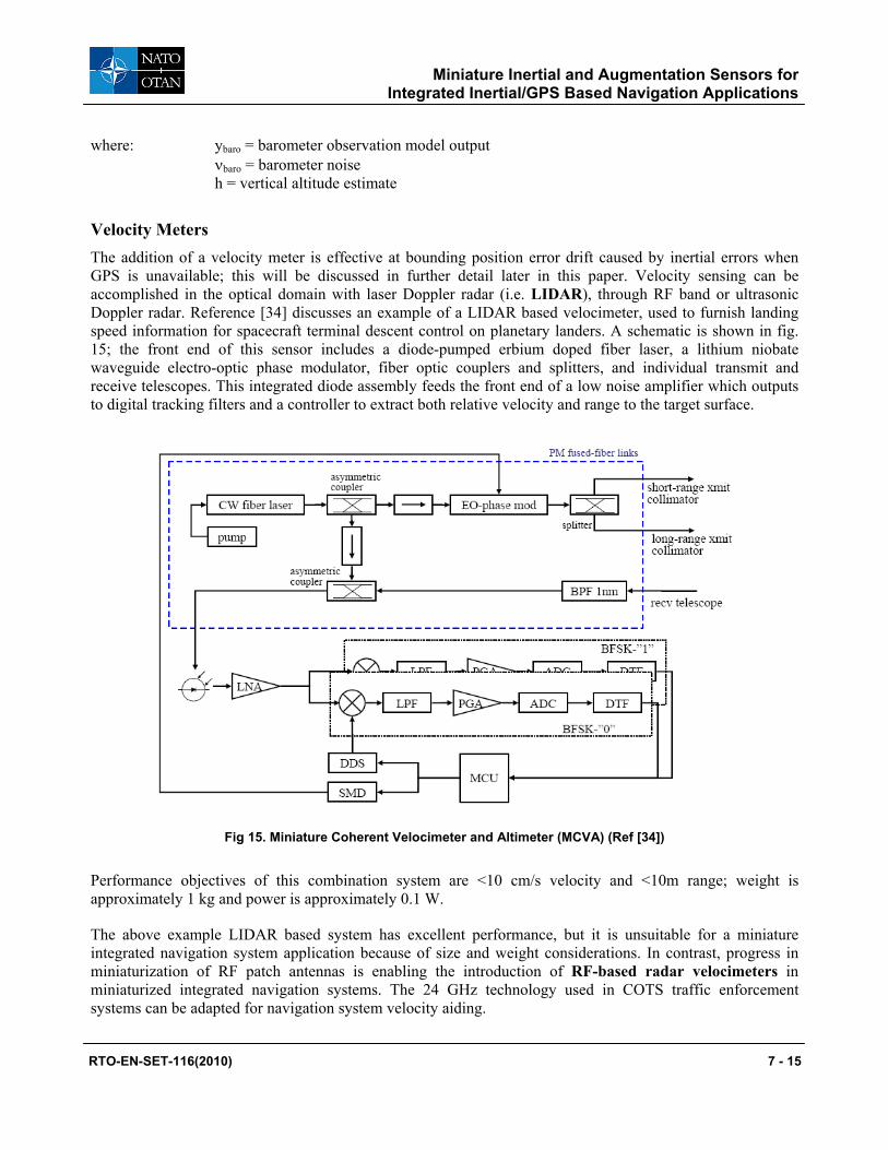
Velocity Meters The addition of a velocity meter is effective at bounding position error drift caused by inertial errors when GPS is unavailable; this will be discussed in further detail later in this paper. Velocity sensing can be accomplished in the optical domain with laser Doppler radar (i.e. LIDAR), through RF band or ultrasonic Doppler radar. Reference [34] discusses an example of a LIDAR based velocimeter, used to furnish landing speed information for spacecraft terminal descent control on planetary landers. A schematic is shown in fig. 15; the front end of this sensor includes a diode-pumped erbium doped fiber laser, a lithium niobate waveguide electro-optic phase modulator, fiber optic couplers and splitters, and individual transmit and receive telescopes. This integrated diode assembly feeds the front end of a low noise amplifier which outputs to digital tracking filters and a controller to extract both relative velocity and range to the target surface.
Fig 15. Miniature Coherent Velocimeter and Altimeter (MCVA) (Ref [34])
Performance objectives of this combination system are <10 cm/s velocity and <10m range; weight is approximately 1 kg and power is approximately 0.1 W.
The above example LIDAR based system has excellent performance, but it is unsuitable for a miniature integrated navigation system application because of size and weight considerations. In contrast, progress in miniaturization of RF patch antennas is enabling the introduction of RF-based radar velocimeters in miniaturized integrated navigation systems. The 24 GHz technology used in COTS traffic enforcement systems can be adapted for navigation system velocity aiding.
RTO-EN-SET-116(2010) 7 - 15
Miniature Inertial and Augmentation Sensors for Integrated Inertial/GPS Based Navigation Applications
Figure 16 shows a basic patch antenna element produced by InnoSenT GmbH (www.innosent.de) with corresponding schematic. The patch array shown has separate transmit and receive antennas, demodulating the received signal in-phase and in quadrature with the transmission signal enables determination of the sign of the velocity measurement (i.e. sensed object moving toward or away from sensor).
Fig 16. Basic Transmit and Receive Radar sensor with InnoSenT 8x8 Patch Array (Approx. 3 in x 3 in)
Reference [36] presents an algorithm for integrating velocity measurements into a navigation solution. A simple model is used which includes velocity error and velocity white noise process terms. The velocity observation model is given by:
[ ] [ ][ ][ ] [ ][ ] νδψ doppe
dopp
ee
edopp
e VCVCz +−∧= [11]
where: z = velocity observables in Doppler frame Ce
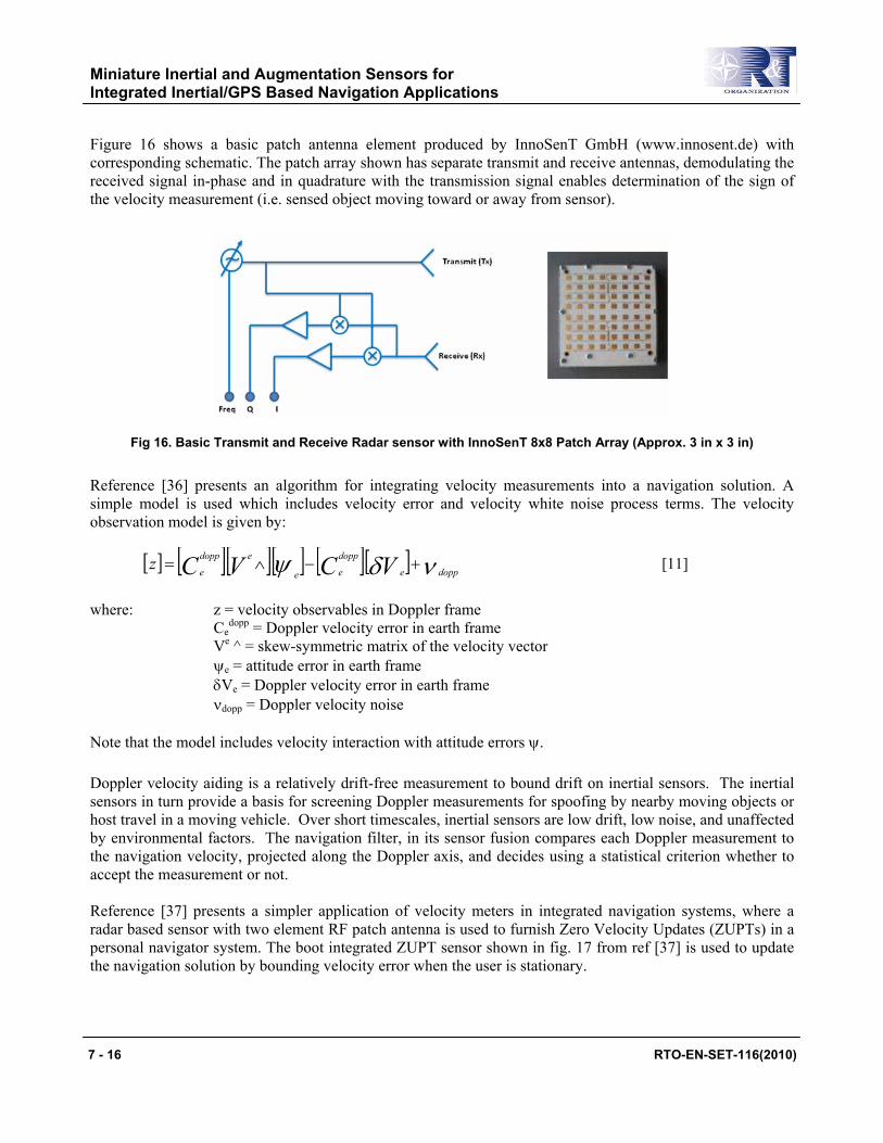
dopp = Doppler velocity error in earth frame Ve ^ = skew-symmetric matrix of the velocity vector ψe = attitude error in earth frame δVe = Doppler velocity error in earth frame νdopp = Doppler velocity noise Note that the model includes velocity interaction with attitude errors ψ. Doppler velocity aiding is a relatively drift-free measurement to bound drift on inertial sensors. The inertial sensors in turn provide a basis for screening Doppler measurements for spoofing by nearby moving objects or host travel in a moving vehicle. Over short timescales, inertial sensors are low drift, low noise, and unaffected by environmental factors. The navigation filter, in its sensor fusion compares each Doppler measurement to the navigation velocity, projected along the Doppler axis, and decides using a statistical criterion whether to accept the measurement or not. Reference [37] presents a simpler application of velocity meters in integrated navigation systems, where a radar based sensor with two element RF patch antenna is used to furnish Zero Velocity Updates (ZUPTs) in a personal navigator system. The boot integrated ZUPT sensor shown in fig. 17 from ref [37] is used to update the navigation solution by bounding velocity error when the user is stationary.
7 - 16 RTO-EN-SET-116(2010)
Miniature Inertial and Augmentation Sensors for Integrated Inertial/GPS Based Navigation Applications
Fig 17. Boot-heel integrated RF Velocity Sensor for Personal Navigation (Ref. [37])
This approach is a variant on a class of foot-mounted navigation systems (refs. 38-40) that employ compact and low power automotive grade MEMS inertial sensors and manage their larger drifts with zero velocity measurements on each footfall. Magnetic attitude sensing vs. MEMS gyroscopes are typically used in these systems. There is no mechanism in the foot mounted system architecture to control heading gyro drift. Reference [41] proposed a novel approach to controlling foot mounted gyro drift – use of foot-to-foot RF range measurements. Similar to foot sensor based ZUPT measurements, RF ranging gives observability into heading gyro drift on each footstep and enables use of compact automotive grade MEMS gyros for precision GPS-denied pedestrian navigation.
There are two challenges for all approaches that employ foot-mounted sensing. First responders and dismounted soldiers have low tolerance for any boot mounted instrument that interferes with operational mobility. Ideally all instrumentation should be mounted conformally on the boot or embedded in the heel in a way that does not affect walking dynamics. Secondly, hard-wired interconnects between boot and mid-body or pack mounted equipment are not desirable. The goal in this foot mounted design space is a highly compact, human motion powered suite of navigation sensors.
Timing Clocks In all applications a small, low power, highly accurate clock is required for processing purposes. Reference [42] describes a miniature atomic clock (MAC) under development as an intermediate step towards a full chip scale atomic clock (CSAC). The MAC is a complete packaged atomic clock with overall size 10 cm3 and power consumption <200 mW that employs similar technology as the miniaturized atomic magnetometer discussed above. The CSAC program was a DARPA initiative that funded multiple teams with the objective of developing a miniature timing reference with volume <1 cm3 and power <30 mW with a timing frequency stability of 1 part in 1011 over an hour [Ref 43].
The MAC described in references [42, 44] is a collaborative effort between Symmetricom, Draper Laboratory, and Sandia National Lab and is shown schematically in figure 18.
RTO-EN-SET-116(2010) 7 - 17
Miniature Inertial and Augmentation Sensors for Integrated Inertial/GPS Based Navigation Applications
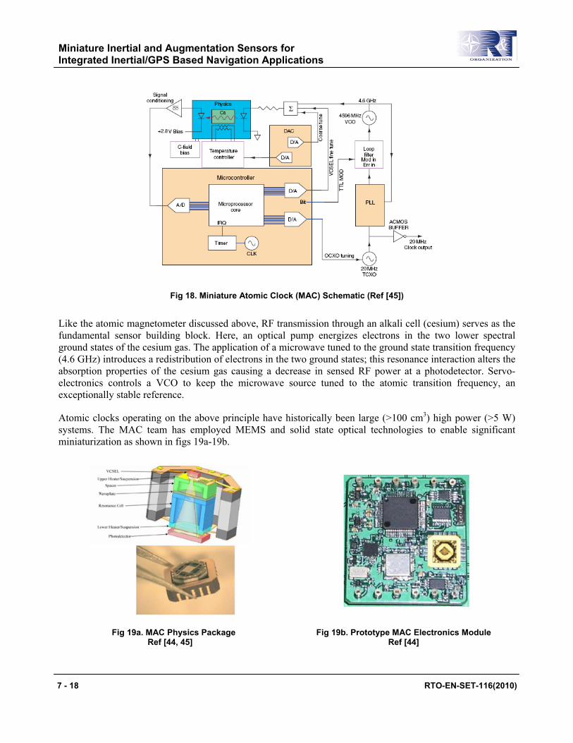
Fig 18. Miniature Atomic Clock (MAC) Schematic (Ref [45])
Like the atomic magnetometer discussed above, RF transmission through an alkali cell (cesium) serves as the fundamental sensor building block. Here, an optical pump energizes electrons in the two lower spectral ground states of the cesium gas. The application of a microwave tuned to the ground state transition frequency (4.6 GHz) introduces a redistribution of electrons in the two ground states; this resonance interaction alters the absorption properties of the cesium gas causing a decrease in sensed RF power at a photodetector. Servo-electronics controls a VCO to keep the microwave source tuned to the atomic transition frequency, an exceptionally stable reference.
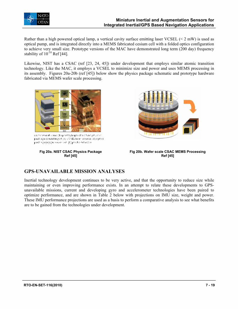
Atomic clocks operating on the above principle have historically been large (>100 cm3) high power (>5 W) systems. The MAC team has employed MEMS and solid state optical technologies to enable significant miniaturization as shown in figs 19a-19b.
Fig 19a. MAC Physics Package Ref [44, 45]
Fig 19b. Prototype MAC Electronics Module Ref [44]
7 - 18 RTO-EN-SET-116(2010)
Miniature Inertial and Augmentation Sensors for Integrated Inertial/GPS Based Navigation Applications
Rather than a high powered optical lamp, a vertical cavity surface emitting laser VCSEL (< 2 mW) is used as optical pump, and is integrated directly into a MEMS fabricated cesium cell with a folded optics configuration to achieve very small size. Prototype versions of the MAC have demonstrated long term (200 day) frequency stability of 10-10 Ref [44].
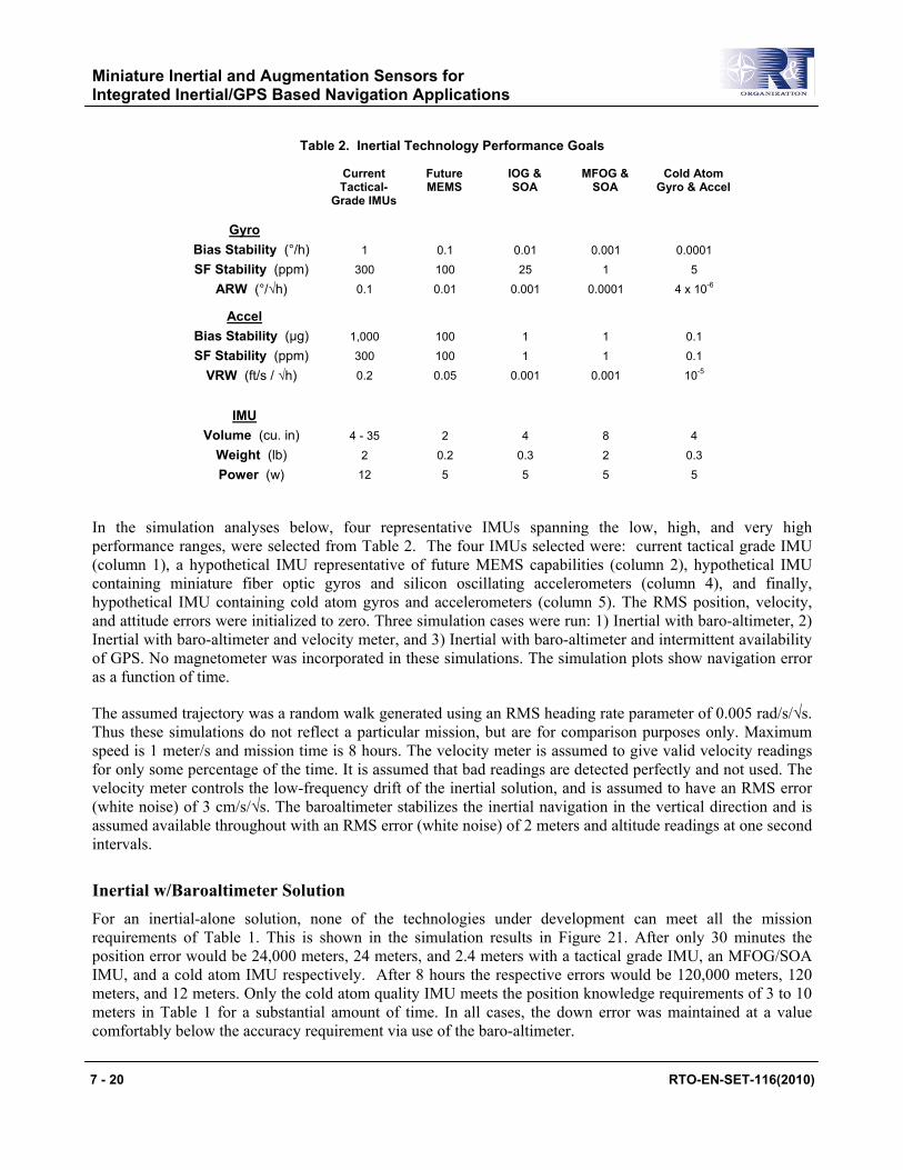
Likewise, NIST has a CSAC (ref [23, 24, 45]) under development that employs similar atomic transition technology. Like the MAC, it employs a VCSEL to minimize size and power and uses MEMS processing in its assembly. Figures 20a-20b (ref [45]) below show the physics package schematic and prototype hardware fabricated via MEMS wafer scale processing.
Fig 20a. NIST CSAC Physics Package Ref [45]
Fig 20b. Wafer scale CSAC MEMS Processing Ref [45]
GPS-UNAVAILABLE MISSION ANALYSES
Inertial technology development continues to be very active, and that the opportunity to reduce size while maintaining or even improving performance exists. In an attempt to relate these developments to GPS-unavailable missions, current and developing gyro and accelerometer technologies have been paired to optimize performance, and are shown in Table 2 below with projections on IMU size, weight and power. These IMU performance projections are used as a basis to perform a comparative analysis to see what benefits are to be gained from the technologies under development.
RTO-EN-SET-116(2010) 7 - 19
Miniature Inertial and Augmentation Sensors for Integrated Inertial/GPS Based Navigation Applications
Table 2. Inertial Technology Performance Goals
Current Tactical-
Grade IMUs
Future MEMS
IOG & SOA
MFOG & SOA
Cold Atom Gyro & Accel
Gyro
Bias Stability (°/h) SF Stability (ppm)
ARW (°/√h)
1 300 0.1
0.1 100 0.01
0.01 25
0.001
0.001 1
0.0001
0.0001 5
4 x 10⁻⁶
Accel
Bias Stability (µg) SF Stability (ppm)
VRW (ft/s / √h)
1,000 300 0.2
100 100 0.05
1 1
0.001
1 1
0.001
0.1
0.1 10-5
IMU
Volume (cu. in) Weight (lb) Power (w)
4 - 35 2
12
2 0.2 5
4 0.3 5
8 2 5
4 0.3 5
In the simulation analyses below, four representative IMUs spanning the low, high, and very high performance ranges, were selected from Table 2. The four IMUs selected were: current tactical grade IMU (column 1), a hypothetical IMU representative of future MEMS capabilities (column 2), hypothetical IMU containing miniature fiber optic gyros and silicon oscillating accelerometers (column 4), and finally, hypothetical IMU containing cold atom gyros and accelerometers (column 5). The RMS position, velocity, and attitude errors were initialized to zero. Three simulation cases were run: 1) Inertial with baro-altimeter, 2) Inertial with baro-altimeter and velocity meter, and 3) Inertial with baro-altimeter and intermittent availability of GPS. No magnetometer was incorporated in these simulations. The simulation plots show navigation error as a function of time.
The assumed trajectory was a random walk generated using an RMS heading rate parameter of 0.005 rad/s/√s. Thus these simulations do not reflect a particular mission, but are for comparison purposes only. Maximum speed is 1 meter/s and mission time is 8 hours. The velocity meter is assumed to give valid velocity readings for only some percentage of the time. It is assumed that bad readings are detected perfectly and not used. The velocity meter controls the low-frequency drift of the inertial solution, and is assumed to have an RMS error (white noise) of 3 cm/s/√s. The baroaltimeter stabilizes the inertial navigation in the vertical direction and is assumed available throughout with an RMS error (white noise) of 2 meters and altitude readings at one second intervals.
Inertial w/Baroaltimeter Solution For an inertial-alone solution, none of the technologies under development can meet all the mission requirements of Table 1. This is shown in the simulation results in Figure 21. After only 30 minutes the position error would be 24,000 meters, 24 meters, and 2.4 meters with a tactical grade IMU, an MFOG/SOA IMU, and a cold atom IMU respectively. After 8 hours the respective errors would be 120,000 meters, 120 meters, and 12 meters. Only the cold atom quality IMU meets the position knowledge requirements of 3 to 10 meters in Table 1 for a substantial amount of time. In all cases, the down error was maintained at a value comfortably below the accuracy requirement via use of the baro-altimeter.
7 - 20 RTO-EN-SET-116(2010)

Miniature Inertial and Augmentation Sensors for Integrated Inertial/GPS Based Navigation Applications
Figure 21a. Tactical-Grade IMU Figure 21b. MFOG/SOA IMU Figure 21c. Cold Atom IMU
Figure 21. Inertial-only Solution - No Velocity Meter
Inertial with Baroaltimeter plus Velocity Meter Figures 22 through 25 show simulation results when a velocity meter is included. The tradeoff parameter is the probability of a good velocity measurement at each time step (one second increments) for each axis (denoted pv(on) in the plots). Simulated probabilities are for pv(on) equal to 0.03, 0.10, and 0.50. The probabilities are independent over axes, so that one, two or three axes could have bad measurements at the same time step. Figure 22 shows error spiking (sometimes to very high values) for the current tactical-grade IMU at low probability levels; this is attributable to significant periods of measurement outage. Note that the position error is reduced after the spikes; this is due to the correlations built up between position and velocity during the period of the spike, which is used to reduce position errors when good measurements are subsequently obtained from the velocity meter. The Future MEMS IMU (Figure 23), while showing little improvement in average position error over the current MEMS IMU, significantly bounds the instantaneous error spikes. There is essentially no error spiking with the MFOG/SOA IMU (Figure 24) or the Cold Atom IMU (Figure 25) even at very low probability levels.
Figure 22a. Pv(on) = 0.03 Figure 22b. Pv(on) = 0.10 Figure 22c. Pv(on) = 0.50
Figure 22. Current Tactical-Grade IMU
RTO-EN-SET-116(2010) 7 - 21

Miniature Inertial and Augmentation Sensors for Integrated Inertial/GPS Based Navigation Applications
Figure 23a. Pv(on) = 0.03 Figure 23b. Pv(on) = 0.10 Figure 23c. Pv(on) = 0.50
Figure 23. Future MEMS IMU
Figure 24a. Pv(on) = 0.03 Figure 24b. Pv(on) = 0.10 Figure 24c. Pv(on) = 0.50
Figure 24. MFOG/SOA IMU
Figure 25a. Pv(on) = 0.03 Figure 25b. Pv(on) = 0.10 Figure 25c. Pv(on) = 0.50
Figure 25. Cold Atom IMU
When a velocity meter is used, it dominates in the ability to maintain high accuracy; there is only a slight reduction in rms position error after 8 hours using an MFOG/SOA IMU compared to a current tactical-grade IMU (~26 meters vs. ~28 meters along North and East for the case Pv(on) = 0.50). Even with a velocity meter none of the inertial technologies meets the 1 to 3 meters position knowledge requirements in Table 1 for more than a few minutes. All the technologies can meet the 10 meter requirement for at least one hour with pv(on) at 50 percent. Therefore, the major driver for improving the performance of the IMU would be to eliminate or reduce the intermittent position error spikes, when the velocity meter has low probability of providing accurate measurements. For a very high performance IMU such as the cold atom, comparing Figures 25c and 21c show that the velocity meter smooths the inertial solution, but has little effect on average position error (~10 meters vs. ~12 meters inertial-alone).
7 - 22 RTO-EN-SET-116(2010)
Miniature Inertial and Augmentation Sensors for Integrated Inertial/GPS Based Navigation Applications
Inertial with Baroaltimeter plus Intermittent GPS Figure 26 shows the simulation results for three IMUs with no velocity meter, but with intermittent GPS availability, as in an autonomous land vehicle mission. GPS is assumed to be available such that one three-axis measurement of position and velocity is obtained every 120 s. The GPS signal allows the navigation solution to be bounded. The benefits of high performing IMUs for meeting the mission requirements in Table 1 are clearly evident in this situation.
Figure 26a. Tactical-Grade IMU Figure 26b. MFOG/SOA IMU Figure 26c. Cold Atom IMU
Figure 26. Autonomous Land Vehicle, Intermittent GPS - 1 Hour
INTEGRATED NAVIGATION: TEST CASE
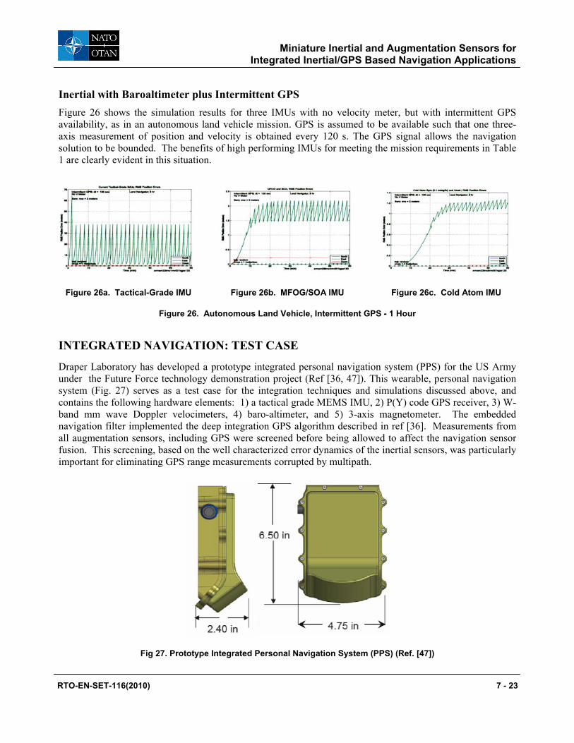
Draper Laboratory has developed a prototype integrated personal navigation system (PPS) for the US Army under the Future Force technology demonstration project (Ref [36, 47]). This wearable, personal navigation system (Fig. 27) serves as a test case for the integration techniques and simulations discussed above, and contains the following hardware elements: 1) a tactical grade MEMS IMU, 2) P(Y) code GPS receiver, 3) W-band mm wave Doppler velocimeters, 4) baro-altimeter, and 5) 3-axis magnetometer. The embedded navigation filter implemented the deep integration GPS algorithm described in ref [36]. Measurements from all augmentation sensors, including GPS were screened before being allowed to affect the navigation sensor fusion. This screening, based on the well characterized error dynamics of the inertial sensors, was particularly important for eliminating GPS range measurements corrupted by multipath.
Fig 27. Prototype Integrated Personal Navigation System (PPS) (Ref. [47])
RTO-EN-SET-116(2010) 7 - 23

Miniature Inertial and Augmentation Sensors for Integrated Inertial/GPS Based Navigation Applications
The Draper multi-sensor navigator was evaluated in an “urban canyon” test area with severe GPS satellite obscuration and multipath and also on an eight floor office building indoor course. Figures 28 and 29 below show navigation results on the outdoor urban canyon track, contrasting the poor results from a GPS-only solution against computed position from the PPS.
Fig 28. “Urban Canyon” Navigation: GPS Only Ref [47]
Fig 29. “Urban Canyon” Navigation: Integrated PPS Ref [47]
Figure 30 shows the transition from outdoors to indoors, where GPS was completely unavailable (ref [47]). Indoor performance over 20 minutes of GPS denial was consistent with predictions from simulations in Figure 25b; CEP error over 12 runs was about 5 m. This included “stress” scenarios that exercised position and heading initialization under GPS challenged conditions.
Fig 30. Indoor Navigation with Integrated PPS (Ref. [47])
For multi-sensor navigator design, a key and often under-appreciated IMU parameter is the characteristic time associated with IMU error state stability. The design philosophy is to construct a navigator to operate on high quality but intermittent augmentation measurements which as a group give complete observability onto IMU error states. A higher level of error stability, with a tolerance for sparser augmentation, can come from careful sensor packaging and thermal management of lower quality inertial instruments. This path, in the short term,
7 - 24 RTO-EN-SET-116(2010)
Miniature Inertial and Augmentation Sensors for Integrated Inertial/GPS Based Navigation Applications
will likely lead to a more compact and lower power system. A takeaway of the simulations in this section is that angle random walk, which is usually the focus of new sensor design, is not always the dominant parameter in system performance.
SUMMARY
In this paper we have discussed some of the ongoing inertial sensor technology development that is oriented towards higher performing, small size IMUs, and suitable for multi-sensor integration with GPS and other augmentation sensors. Some of these design concepts are evolutionary and some quite revolutionary. Comparative simulations were performed, using these sensors in hypothetical IMUs, to examine the impact on position error growth in a GPS-denied environment. Unsurprisingly, accuracy performance degrades rapidly when GPS is denied and the system relies on an inertial-only solution.
A survey on magnetometers, velocity meters, barometers, and timing sources was presented, with an emphasis placed on identifying accurate, miniature versions of these sensors that are currently available or well along in development. Simulations showed that the addition of these sensors can suppress position error growth under GPS-denied situations when integrated properly into the navigation solution. It is only when inertial performance equivalent to that expected from cold atom technology is available that the some of the reliance on other aiding schemes can be relaxed in GPS-denied situations.
Simulations indicate the inclusion of a velocity meter to augment the inertial solution improves accuracy over short periods of time in the GPS-denied environment. This was demonstrated experimentally during testing of a Draper lab prototype personal navigation system. The Draper PPS system, an integration of a MEMS tactical grade IMU, P(Y)-Code GPS, magnetometer, barometer and Doppler velocity meter, demonstrated better than 5 m position accuracy in urban canyon and GPS-denied indoor testing.
ACKNOWLEDGEMENTS
Thanks to Jess Tawney from Draper Laboratory for information on Photonic Crystal Fibers (PCFs) and the PC-IFOG, and Rick Stoner and Steve Smith from Draper Laboratory for information on the Atom Interferometers.
This paper is an updated and expanded version of the paper ‘Small Inertial Navigation Sensors for GPS-Unavailable Environments” by Barbour, Gustafson, Hopkins, published in the proceedings of the NATO SET 104 symposium (Ref. [50])
REFERENCES
[1] Datasheet: Integrated Guidance Systems website: <http://www.igsllc.com/docs/IGS2xx%20Data%20Sheet%200509.pdf>
[2] Datasheet: Atlantic Inertial Systems website: <http://www.atlanticinertial.com/uploads/pdfs/SINAV02_07.pdf>
[3] Barbour N., Inertial Navigation Sensors (SET116), NATO RTO SET116 Symposium on Low Cost Navigation Sensors, December 2008, March 2009, March 2010
[4] Pavlath G., Fiber Optic Gyros: The Vision Realized, 18th International Conference on Optical Fiber Sensors, Cancun, Mexico, October 2006.
RTO-EN-SET-116(2010) 7 - 25

Miniature Inertial and Augmentation Sensors for Integrated Inertial/GPS Based Navigation Applications
[5] Divakaruni S. and Sanders S., Fiber Optic Gyros – A Compelling Choice for High Accuracy Applications, 18th International Conference on Optical Fiber Sensors, Cancun, Mexico, October 2006.
[6] KVH Industries Inc., An Update on KVH Fiber Optic Gyros and Their Benefits Relative to Other Gyro Technologies, March 2007.
[7] Tawney J. et al, Photonic Crystal Fiber IFOGs, Optical Society of America, 18th International Conference on Optical Fiber Sensors, Cancun, Mexico, October 2006.
[8] Sanders G., Strandjord L., and Qiu T., Hollow Core Fiber Optic Ring Resonator for Rotation Sensing, 18th International Conference on Optical Fiber Sensors, Cancun, Mexico, October 2006.
[9] Suzuki K. et al, Monolithically Integrated Resonator Micro-optic Gyro on Silica Planar Lightwave Circuit, Journal of Lightwave Technology, Vol 18, No 1, January 2000.
[10] Li G. et al, Design, Fabrication, and Characterization of an Integrated Optic Passive Resonator for Optical Gyroscopes, ION Annual Meeting, Dayton, OH, June 2004.
[11] Scheuer J. and Yariv A., Sagnac Effect in Coupled resonator Slow-Light Waveguide Structures, Physical Review Letters, Vol 96, 053901, February 2006.
[12] Steinberg B. et al, Slow-Light Waveguides with Mode Degeneracy: Rotation Induced Super Structures and Optical Gyroscopes, 18th International Conference on Optical Fiber Sensors, Cancun, Mexico, October 2006.
[13] Weinberg M. and Kourepenis A., Error Sources in In-Plane Silicon Tuning Fork Gyroscopes, JMEMS, Vol 15, No. 3, 2006.
[14] Mezentsev A. et al, Subminiature Dynamically Tuned Gyroscope - Design and Development, 11th St. Petersburg International Conference on Integrated Navigation Systems, St. Petersburg, Russia, May 2004.
[15] Dauwalter C. and Ha J., Magnetically Suspended MEMS Spinning Wheel Gyro, IEEE A&E Systems Magazine, Vol 20, No 2, Feb 2005.
[16] Dussy S. et al, MEMS Gyro for Space Applications – Overview of European Activities, AIAA GN&C Conference and Exhibit, San Francisco, CA, August 2005.
[17] Shkel A., Type I and Type II Micromachined Vibratory Gyroscopes, Position, Location, And Navigation Symposium, IEEE/ION, Coronado, CA, April 2006.
[18] Hopkins R. et al, The Silicon Oscillating Accelerometer: A High-Performance MEMS Accelerometer for Precision Navigation and Strategic Guidance Applications, ION 61st Annual Meeting, Cambridge, MA, June 2005.
[19] Jaffe, R., Ashton, T. Madni, A., Advances in Ruggedized Quartz MEMS Inertial Measurement Units, Position, Location, And Navigation Symposium, IEEE/ION, Coronado, CA, April 2006.
[20] Le Traon O. et al, A New Quartz Monolithic Differential Vibrating Beam Accelerometer, Position, Location, And Navigation Symposium, IEEE/ION, Coronado, CA, April 2006.
[21] Kasevich M. and Salomon C. - Editors, Special Issue: “Quantum Mechanics for Space Application: From Quantum Optics to Atom Optics and General Relativity”, Applied Physics B, Vol 84, August 2006.
[22] Zatezalo A. et al, Bose Einstein Interferometry and its Applications to Precision Undersea Navigation, IEEE 2008, 1-4244-1537-3
[23] Kitching J., Chip Scale Atomic Devices, Precision Instruments based on Lasers, Atom and MEMS, Microsystems Technology Symposium, San Jose CA, March 2009
[24] Press Release: 1 November 2007: New NIST Mini-Sensor May Have Biomedical and Security Applications Ultrasensitive Prototype Device Approaches Gold Standard for Magnetic Field Detection, Contact info: Laura Ost (303) 497-4880, www.nist.gov
7 - 26 RTO-EN-SET-116(2010)
Miniature Inertial and Augmentation Sensors for Integrated Inertial/GPS Based Navigation Applications
[25] Strangeway R., 11 June 2001, Fluxgate Magnetometer for NASA/GSFC ST5 Mission, http://dawn.ucla.edu/st5/design.html
[26] PNI Sensor Corporation, 133 Aviation Blvd., Suite 101, Santa Rosa, CA 95403-1084, www.pnicorp.com
[27] McLean, S., S. Macmillan, S. Maus, V. Lesur, A. Thomson, and D. Dater, December 2004, The US/UK World Magnetic Model for 2005-2010, NOAA Technical Report NESDIS/NGDC-1. http://www.ngdc.noaa.gov/geomag/WMM/data/TRWMM_2005.pdf
[28] Technical Articles: Magnetic Sensor Overview: <http://www.honeywell.com/sites/>
[29] Biezad D., Integrated Navigation and Guidance Systems, AIAA Education Series, © 1999
[30] Savage P., Introduction to Strapdown Inertial Navigation Systems, Strapdown Associates, © 1996
[31] Groves P., Principles of GNSS, Inertial, and Multisensor Integrated Navigation Systems, Artech House, © 2008
[32] Seo J. et al, Bias Suppression of GPS Measurement in Inertial Navigation System Vertical Channel, Proc. of IEEE/ION PLANS Apr. 2006 pp. 143-147
[33] VTI Technologies website: www.vti.fi
[34] Chang D., Miniature Coherent Velocitmeter and Altimeter (MCVA) for the Terminal Descent Control on Lunar and Planetary Landers, JPL Manuscript
[36] Landis D. et. al, A Deep Integration Estimator for Urban Ground Navigation, IEEE PLANS 2006, 0-7803-9454-2
[37] Lal A. et. al, Velocity Sensor Assisted Micro Inertial Measurement for GPS Denied Personal Navigation, Joint Navigation Conference (JNC) 2009, Orlando, FL, June 2009
[38] L. Ojeda and J .Borenstein, Non-GPS Navigation for Emergency Responders, 2006 International Joint Topical Meeting: “Sharing Solutions for Emergencies and Hazardous Environments”
[39] Website: www.g-trax.com
[40] E. Foxlin, NavShoeTM Pedestrian Inertial Navigation Technology Brief, 2006 WPI Workshop on Precision Indoor Personnel Location and Tracking for Emergency Responders
[41] Brand T. et. al, Foot-to-Foot Range Measurement as an Aid to Personal Navigation, Proc. ION 59th AM. Albuquerque, NM, June 2003, pp. 113-125
[42] Lutwak R. et al, The MAC - A Miniature Atomic Clock, Joint IEEE International Frequency Control Symposium and Precise Time and Time Interval (PTTI) Systems and Applications Meeting, Vancouver, BC, Canada, August 2005.
[43] Mescher M. et al, An Ultra-Low-Power Physics Package for a Chip Scale Atomic Clock, Transducers 05, Seoul, Korea, June 2005.
[44] Lutwak R., The Miniature Atomic Clock – Pre-Production Results, IEEE Frequency Control Symposium, May 2007
[45] Knappe S., Emerging Topics: MEMS Atomic Clocks, in Y. Gianchandani, O. Tabata, and H. Zappe (eds.) Comprehensive Microsystems, 2007, Elsevier, Netherlands
[46] Datasheet: <www.ssec.honeywell.com/magnetic/datasheets/hmc1043.pdf>
[47] Sherman, P., et. al., Precision Positioning System –Autonomous GPS-Denied Navigation for the Dismounted Soldier, WPI Indoor Personnel Location and Tracking for Emergency Responders, Aug 4-5, 2008
[48] http://www.gemsys.ca/Technology/Papers/GEM_Brief_Review_of_Quantum_Magnetometers.pdf
[49] Kayton M., Fried W. (eds) Avionics Navigation Systems. 2nd edition, Wiley 1997
RTO-EN-SET-116(2010) 7 - 27

Miniature Inertial and Augmentation Sensors for Integrated Inertial/GPS Based Navigation Applications
[50] Barbour N. Gustafson D., Hopkins R., Small Inertial Navigation Sensors for GPS-Unavailable Environments, NATO RTO SET104 Symposium, Military Capabilities Enabled by Advances in Navigation Sensors, Antalya, Turkey, October 2007
7 - 28 RTO-EN-SET-116(2010)