MINI-INVERTERS SINGLE PHASE THREE PHASE · EBST-MVP The EBST-MVP pure sine wave inverter represents...
32
MINI-INVERTERS SINGLE PHASE THREE PHASE INVERTERS
Transcript of MINI-INVERTERS SINGLE PHASE THREE PHASE · EBST-MVP The EBST-MVP pure sine wave inverter represents...

MINI-INVERTERSSINGLE PHASETHREE PHASE
INVERTERS

YOUR TRUSTED PARTNER
ABOUT US
The Management of AimLite Lighting Products is committed to constantly provide products that meet or exceed the requirements and expectations of our customers while at the same time making the company successful.
Our ISO/IEC 17025 certified laboratory is qualified by CSA International under the CPC (Certification by Category) program which allows us to conduct safety and performance evaluations and to perform over 100 different tests on our products. This allows AimLite to certify new custom products quickly and launch to the market.
AimLite’s target is to maintain and improve its quality through programs that enable employees to do their job right the first time and use the best suppliers that share these same values.
Our team consists of some of the most knowledgeable and recognizable people in the Canadian emergency and lighting industry.
NEW PRODUCT DEVELOPMENT
Our engineering and marketing team is composed of specialists ranging from a variety of technical backgrounds which allows us to develop a multitude of new products to meet today’s market needs and requirements. Our focus is to design innovative products at a competitive price to set ourselves ahead of our competition while maintaining industry standards such as long life and energy efficiency.
CUSTOMER SATISFACTION
Customer satisfaction is the company’s main priority: we want to be our customers’ preferred supplier.
Our customer service department is comprised of highly trained, knowledgeable and bilingual sales representatives whose only goal is to meet the needs of the customers. Sales staffs are continuously trained to keep them abreast of the latest lighting trends, technologies and developments so they may actively serve customers, resolve issues, initiate changes, and teach co-workers.
Our technicians have extensive academic and practical experience with degrees in engineering and administration, allowing us to offer technical support in the retail, distribution and manufacturing sectors.
AimLite’s management is dedicated to its customers, employees and safety.
YOUR TRUSTED PARTNER

RELAY DIAGRAM

EMERGENCY LIGHTING INVERTER SYSTEM ORDERING INFORMATION
JJOOBB NNAAMMEE
JJOOBB LLOOCCAATTIIOONN CITY PROVINCE
WWHHAATT IISS TTHHEE IINNVVEERRTTEERR PPOOWWEERRIINNGG//TTYYPPEE OOFF LLOOAADD INCANDESCENT FLUORESCENTS HID COMPUTERS
OOTTHHEERR
WWIILLLL TTHHEE LLOOAADD BBEE NNOORRMMAALLLLYY OONN OONNLLYY WWHHEENN TTHHEERREE IISS UUTTIILLIITTYY AACC PPOOWWEERR??
IIFF NNOOTT,, SSPPEECCIIFFYY NORMALLY OFF LOAD KW _________ NORMALLY ON LOAD KW ________
TTOOTTAALL SSIIZZEE RREEQQUUIIRREEMMEENNTT//CCAAPPAACCIITTYY KW _________ KVA ________
BBAATTTTEERRYY TTYYPPEE STANDARD 10 YR SEALED LEAD CALCIUM
BBAATTTTEERRYY BBAACCKK--UUPP TTIIMMEE 30 MIN 60 MIN 90 MIN 120 MIN OTHER ________ MIN
VVOOLLTTAAGGEE IINNPPUUTT, V______
SINGLE PHASE OR 3 PHASE
2 WIRE 3 WIRE OR 3 WIRE 4 WIRE
VVOOLLTTAAGGEE OOUUTTPPUUTT, V_____
SINGLE PHASE OR 3 PHASE
2 WIRE 3 WIRE OR 3 WIRE 4 WIRE
IIFF NNEEEEDDEEDD,, TTHHEE NNUUMMBBEERR OOFF OOUUTTPPUUTT CCIIRRCCUUIITT BBRREEAAKKEERRSS AANNDD AAMMPP RREEQQUUIIRREEMMEENNTTSS: ________________________________________
HHOOWW MMAANNYY OOFF TTHHEEMM AARREE NORMALLY ON ______ NORMALLY OFf _____
OOPPTTIIOONNSS DDEESSIIRREEDD
EXTERNAL MAINTENANCE BYPASS SWITCH
REMOTE ALARM AND CONTROL PANEL
OOTTHHEERR
INVERTER SYSTEM ORDERING INFORMATION
1INVERTER SYSTEM ORDERING INFORMATION

WHY WE NEED INVERTERS
NEED FOR EMERGENCY SYSTEMS
Public buildings carry an electrical load. Daily lighting uses a lot of electricity. The power used supplies daily electrical needs, but in emergency situations such as power outages, fire or power fluctuations, that power could be lost. In these situations, electrical back-up systems are needed.
These systems, aka Inverters, automatically monitor the incoming utility to the building and react when the situation of lost power occurs. supplying electricity to the lighting and power loads, required to safely exit the building (egress).
WHY USE EMERGENCY INVERTER SYSTEMS?
Whether it is a loss of power due to storms, an electrical line issue, or a true emergency loss of power, inverters sit quietly on guard, ready to light the way to safety for the public.
Inverters are the choice of the future.
HOW DO EMERGENCY SYSTEMS WORK?
Standard electrical systems run on AC power. Emergency lighting loads also run on AC power, usually as “normally-ON” or “normally-OFF” lighting.
On occasion, back-up will be needed for a mix of both on and off lighting.
Inverter systems are made up of a set of DC batteries and electronics that can convert the DC power from the batteries into an AC power source needed for the emergency lighting loads.
Emergency inverter systems will provide enough emergency AC power for the required time to exit the building if necessary.
WHY USE AN INVERTER OVER EMERGENCY LIGHTING?
When a building is so vast and requires more lighting than just remote heads, its makes economic sense to use an Inverter instead of running thousands of feet of wire and pipe. Also with an inverter there is only one point of service, unlike many emergency lighting units and remotes. For applications such as warehouses which are congested with racking, traditional emergency heads cannot be placed properly for direction or could be hidden all together
HOW DO INVERTERS PERFORM WITHOUT EMERGENCY REMOTES?
The inverter normally is sized to take 25% of the lighting load.This allows regular lighting, to also act as emergency lighting during power failure to illuminate the designed path of egress The inverter load requirement could also include all exit or pictogram signage.
WHAT ARE OTHER BENEFITS?
Designers have always believed that emergency lighting in general is unattractive and obtrusive. The inverter is typically hidden in a electrical room, out of site. Also there are no remotes anywhere since existing lighting (fluorescent, LED, HID and induction) is being utilized. The integrity of the esthetics are not harmed.
2 WHY WE NEED INVERTERS

EBST-MVPThe EBST-MVP pure sine wave inverter represents a unique approach to power failure lighting applications. Pure sine wave inverters are ideal, as opposed to square and modified wave inverters, which will break down electronic ballasts and drivers prematurely. AimLite’s EBST-MVP pure sine wave inverter was designed to run up to 1440W of normally ON or OFF LED, CFL or fluorescent, incandescent lighting fixtures.
NVTRThe NVTR is a single phase pure sine wave dependable lighting inverter system. A traditional solution for life safety egress lighting is through the use of small DC batteries equipment. The central inverter supplies power to existing lighting luminaires, eliminating the need for special emergency lighting fixtures. The central inverter system encompasses a single unit installed in a centralized location.
NV3TRThe NV3TR is one of the most versatile and dependable three phase pure sine wave lighting inverter systems in the market. The use of existing fixtures for emergency lighting and egress assures compliance with minimum illumination code requirements. The extensive combinations of input and output voltages, timed off bus with remote “command on” control, automatic battery testing, and control device override options make the NV3TR your preferred choice.
3EBST + NVTR + NV3TR

OVERVIEW
ELECTRICAL NORMALLY ON 1 OR OFF 120 VAC INPUT AND OUTPUT
MECHANICAL SEPARATE BATTERY COMPARTMENT STEEL CONSTRUCTION
EBST-MVPPURE-SINE WAVE IPSMINI-INVERTER
Normally OFF: By combining a battery unit and off-line inverter with superior 120V lighting performance for all types of lighting fixtures, the EBST-MVP provides exceptional power failure lighting. The typically configured battery unit is paired with an off-line, internally mounted, pure-sine wave inverter. When AC power is present there is no output and the connected fixtures are off, when the AC power fails, the unit outputs 120VAC to the connected lighting fixtures at 100% brightness.
1 Normally ON: This feature is easily activated by connecting a normally-ON lighting circuit to the unit. When AC power is present there is output and the connected lighting fixtures are on. When the AC power fails, the output is then transferring instantaneously to the power failure mode of the inverter and the connected lighting fixtures stay on.
CIRCUITRY • 120 VAC input and 120 VAC
output • Momentary push button test
switch • Diagnostic/pilot LEDs for AC
ON and CHARGE • Fully automatic, current
limited charger • Line latched, low voltage
protection • Brownout and short circuit
protection • Terminal block connectors
for output load • Dimming override control is
standard with ATD option for 1 000 W and more
• Auto transfer switch for 120VAC normally-on lighting circuit (when ordered)
• Maintenance free, sealed lead acid battery(s)
Overload protectors: • 1 000 W: Fuse allowing max
load of 175A and board protector with protection up to 1 100 W
• 1 440 W: Fuse allowing max load of 175A and board protector with protection up to 1 500 W
• Optional automatic-testing, self-diagnostic charger 2:
• Continuously monitors the unit’s status
• Automatically performs battery load testing and auto-cycling at preset intervals
• Indicates malfunctions or auto-test failures
MECHANICAL • 18 Gauge steel construction
(cabinet A and B), 16 Gauge steel construction (cabinet C)
• Universal spider knockout pattern and keyhole mounting slots stamped into back of cabinet
• Multiple conduit entry knockouts
• Air intake and exhaust fan
placed on the sides for 1000W and more
• White powder coat fi nish standard
• Separate battery compartment
APPROVALS • CSA certifi ed to C22.2
#141-15
FEATURES & SPECIFICATIONS
1 For normally ON units without automatic-testing self-diagnostic charger, inverter load needs to be wired to a dedicated non-dimmed circuit. 2 Dimming override control is standard with ATD option for 1 000 W and more.
4 EBST-MVP

EBST-MVP
ORDERING GUIDE
PART NO DESCRIPTION
SHELF001RIGID 14 GAUGE FREE STANDING SHELF (AVAILABLE ONLY WITH 1 000 W, AND 1 440 W)
ACCESSORY MODEL RATINGS
EBST-MVP 12 WHT
SERIES VOLTS (VDC) WATTS (W) CABINET COLOR LOAD OPERATION OPTIONS 1
EBST-MVP 12 - 12 320 - 320 CA - CB -
CABINET ACABINET B
WHT - WHITE ON 2 - OFF -
NORMALLY ONNORMALLY OFF
ATD 3 - AUTO-TEST SELF-DIAGNOSTIC(NON AUDIBLE)
500 - 500 CB - CABINET B1000 - 1 000 CC - CABINET C
1440 - 1 440 CC - CABINET C1 For detailed options descriptions, please consult the options page.2 Note: For normally ON units without automatic-testing self-diagnostic charger, inverter load needs to be wired to a dedicated non dimmed circuit.3 Dimming override control is standard with ATD option for 1 000 W and more.
MODEL VOLTS (VDC) 30 MIN. 60 MIN. 90 MIN. 120 MIN.
EBST-MVP12320 12 320 160 105 80
EBST-MVP12500 12 500 250 165 125
EBST-MVP121000 12 1 000 500 330 250
EBST-MVP121440 12 1 440 720 480 360
WATTS (W) CABINET WITHOUT BATTERY(S)
(LBS)WITH BATTERY(S)(LBS)
320 CABINET A 28.2 52
320 CABINET B 29.2 53
500 CABINET B 29.1 71
1 000 CABINET C 61.3 145
1 440 CABINET C 63.4 189
WEIGHT
DIMENSIONS
CABINET A CABINET B
CABINET C
8-9/16"(218mm)
10-3/16"(259mm)
25-3/4"(653mm)
10-1/16"(256mm)
10-3/16"(259mm)
25-3/4"(653mm)
18"(457mm)
25-3/4"(653mm)
14-9/16"(370mm)
19"(483mm)
30"762mm
27"686mm
SHELF001
EBST-MVP 5
320W
(-) (+)SHUNT
WIR
118-
BU
WIR
118-
GY
BOO
ST
25" YELLOW WIR118-YL
LAM
P RE
LAY
WIR
118-
RD
WIR
118-
BK
20" WIR118-WH
GN
D
NORMALLY ONLIGHTING INPUT
NEU
T12
0V
GN
D
CONTROL INPUT
NEU
T12
0V
CONNECT 120VACLIGHTING CIRCUIT
12
ON
NORMALLY ON OR NORMALLY OFFSWITCH SUPPLIED BY CONTRACTOR
12VBATTERY
(-) (+)
(-)
(+)
INVERTERGND
RJ12REMOTEPANEL
RED
WIR
E
TRANSFERSWITCH
INVERTER OUTPUT
UTILITY POWER
LOAD
12V
CHA
RGER
(-) BAT
(+) BAT
(-) L2(-) L1
(+) L2(+) L1
10 AWG BLACK
10 AWG REDTRA40109/CSATRANSFORMER
RED
120V BLACK
NEUTRAL WHITE
GRE
EN
WHI
TE
BLA
CK
18 A
WG
GRE
EN
WHI
TE
BLA
CK
18 AWG GREEN
HAR028 HAR028
FUSE80A-300V-T
HAR671FUSE HOLDER
4 A
WG
RED
4 A
WG
RED
GND NEUTRAL 120VAC
LOADS
GREEN
WHI
TE
BLA
CK
HAR028
HAR028-JUMPER
WHITE
BLACK
# 18 AWG
GFCI TRIPINDICATOR
(FOR TI OPTION)
M N IR3
62K Ω½W
WHITE
BLACK
BLACK
WHITE
4 AWG BLUE
CONTROLLER BOARD
CONTROLLER BOARD
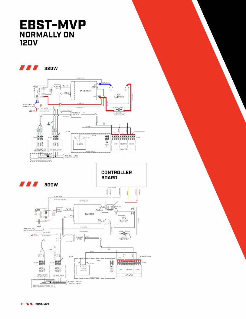
EBST-MVPNORMALLY ON120V
500W
6 EBST-MVP

1000W
12/9/2016 12:23:58 PM f=0.90 T:\Engineering\Projects\Project AB In process\PR-15018_Inverters at 900W and 1440W from Xantrex\04 Concept, design, proto T\Electrical design\1000W Battery Unit Preliminary Design\Drawings\1000W ON\DWG-WD-0141-REV0-20161202.sch (Sheet: 1/1)
These wires must be of the same length
These wires must be of the same length
1N5819-B1N4004
30 ohm 10W
D1D2
13
6 4
9 7
AB
D4
R1
1
A
B
C
D
E
F
A
B
C
D
E
F
1 2 3 4 5 6 7 8 9
2 3
4 5 6 7 8 9 10 11 12 13 14 15
16 1718 29 30 3228 33 35
C
NCNO
coil
K1ELC-RL-12DC20ADPDT
21 22
23 24
HA
R0
28
36 37 38
2527394142
43
19 20 26 31 34 40 44
INVERTERREMOTEPANEL
TRA40109/CSA
HAR778-FUSE-BLOCK(32031T)
FUSE175A-300V-T
TRA40109/CSA
BA
T(-
)
BA
T(-
)
BA
T(+
)
BA
T(+
)
LA
MP
(+)
LA
MP
(+)
LA
MP
(-)
LA
MP
(-)
GND 120VNEUTRAL
LOADS
GND
CBD431-INV1440-CAL
TB1TB2TB3TB4TB5
WIR118-BU
WIR118-GY
WIR118-RD
WIR118-BK
WIR118-YL
WIR
118-W
HB
OO
ST
RE
LA
Y
SH
UN
T(+
)
SH
UN
T(-
)
CAL
1 1 1 11
BO
OS
T
BO
OS
T
CB
D12V
360-I
NV
500
CB
D12V
360-I
NV
500
ELC-INV-SW2000
ELC-INV-SW600-REMO
BATERY UNIT WITH 1000W INVERTER NORMALLY ON
IPL
IPL
IPL
0GN
D
120V
NE
UT
RA
L
LIGHTING INPUT
GN
D
120V
NE
UT
RA
L
CONTROL INPUT
FAN
WIR
118-W
H
WIR118-VT
WIR112-BK
WIR112-RD
WIR114-BK
WIR114-BK
WIR
118-B
K
WIR118-RD
WIR118-BU
WIR118-BK
WIR118-BK
WIR118-RDWIR118-RD
B1 B2
B3 B4
WIR118-BK
WIR118-WH
B5
WIR
135-B
U-1
6IN
WIR
136-R
D-1
6IN
BATPM12-55
TR
AN
SF
ER
SW
ITC
H
BATPM12-55
T175A
/300V
SHUNT 200A/50mVELC-SHUNT-200A
UT
ILIT
Y P
OW
ER
INV
ER
TE
R P
OW
ER
AC LOAD
7EBST-MVP

1 2/9/201 6 1 2:1 7:55 PM f=0.90 T:\Engineering\Projects\Project AB In process\PR-1 501 8_Inverters at 900W and 1 440W from Xantrex\04 Concept, design, proto T\Electrical design\1 000W Battery Unit Preliminary Design\Drawings\1 440W ON\DWG-WD-01 40-R
These wires must be of the same length
These wires must be of the same length
1 N581 9-B1 N4004
D1D2 D3
136 4
9 7AB
D4
1
A
B
C
D
E
F
A
B
C
D
E
F
1 2 3 4 5 6 7 8 9
2 3
4 5 6 7 8 9 1 0 11 1 2 1 3 1 4 1 5
1 6 1 7 1 8 1 9 20 29 30 31 3228 33 34 35
C
NCNO
coil
K1ELC-RL-1 2DC20ADPDT
21 22
23 24
HAR
028
36 37 38
25262739404142
43
44 45 46 47 48 49 50
INVERTERREMOTEPANEL
TRA401 09/CSA
HAR778-FUSE-BLOCK(32031 T)
FUSE1 75A-300V-T
TRA401 09/CSA
BAT(
-)
BAT(
-)
BAT(
+)
BAT(
+)
LAM
P(+)
LAM
P(+)
LAM
P(-)
LAM
P(-)
GND 1 20VNEUTRAL
LOADS
GND
CBD431 -INV1 440-CAL
TB1TB2TB3TB4TB5
WIR11 8-BU
WIR11 8-GY
WIR11 8-RD
WIR11 8-BK
WIR11 8-YL
WIR
118-
WH
BOO
ST
REL
AY
SHU
NT(
+)
SHU
NT(
-)
CAL
1 1 1 11
BOO
ST
BOO
ST
CBD
12V3
60-IN
V500
CBD
12V3
60-IN
V500
ELC-INV-SW2000ELC-INV-SW600-REMO
BATERY UNIT WITH 1 440W INVERTER NORMALLY ON
IPL
IPL
IPL
0
TRA401 09/CSA
BAT(
-)BA
T(+)
LAM
P(+)
LAM
P(-)
BOO
STC
BD12
V360
-INV5
00IP
L
GN
D
120V
NEU
TRAL
LIGHTING INPUT
GN
D
120V
NEU
TRAL
CONTROL INPUT
FAN
WIR
118-
WH
WIR11 8-VT
WIR11 2-BK
WIR11 2-RD
WIR11 4-BK
WIR11 4-BK
WIR
118-
BK
WIR11 8-RD
WIR11 8-BU
WIR11 8-BKWIR11 8-BK
WIR11 8-RDWIR11 8-RD
B1 B2
B3 B4
B5R1
30 ohm 1 0W
WIR
135-
BU-1
6IN
WIR
136-
RD
-16I
N
BATPM1 2-55
TRAN
SFER
SW
ITC
H
BATPM1 2-55
BATPM1 2-55
T175
A/30
0V
SHUNT 200A/50mVELC-SHUNT-200A
UTI
LITY
PO
WER
INVE
RTE
R P
OW
ER
AC LOAD
1440W
MOST POPULAR SETUP
8 MOST POPULAR SETUP

NVTR & NV3TRPURE SINE WAVE INVERTERS
HOW MANY PULSES ARE USED TO ACHIEVE THE WAVE FORM TO COME CLOSEST TO A PURE SINE WAVE?
For the number of “pulses”, this word can be related to the DC Rectifier to charge the batteries, or the first “AC to DC” stage of a double conversion system. The more pulses, the lower the reflected current harmonics (a good thing), and the lower the AC ripple content (also a good thing for the batteries).
Since we use IGBT devices and not SCR devices, we cannot apply the 6-pulse or 12-pulse circuit arrangement. The IGBT switches at a high frequency. 10.8kHZ on the 3-ph models and 17kHZ for the single phase models.
This high frequency allows us to re-create the sine wave with many fine points, to achieve a nearly perfect sine wave.
Some of our inverters are line interactive which incorporates a transformer – which naturally puts out a true sine wave, at no more than 5% VTHD. All other inverter models are double conversion topologies, running at 10.8kHZ to 17kHZ.
Looking at the 10.8kHZ model, it translates to roughly 180 points (or more) per cycle, and will give 3% VTHD under linear loading, not to exceed 5% under non-linear loading.
Most designers of UPS systems are in the 10-20kHZ frequency range, if you go faster/more points, the higher frequency has more losses so your system efficiency will drop.
The output is then filtered to help smooth out the points to achieve the 3% maximum voltage distortion. You should always try to be under 5% for any electrical circuit.
HOW IS PURE SINE WAVE ACHIEVED, WITH NUMEROUS FILTERS OR OTHER COMPONENTS?
Is achieved electronically using fast switching transistors. These are now called IGBT’S (Isolated Gate Bipolar Transistor) that gives designers much more flexibility to control power. They are also now fail-proof, thermally protected and overload protected during fault/temp situations.
ADVANCED DIGITAL MONITORING THE INTELLISTAT TSTM
The NV3TR includes a user-friendly Intellistat TS™ monitor which provides quick, full-access to all of the inverter’s features. This allows all programming to be done directly from the touchscreen display, and provides complete system diagnostics and testing. A colour, TFT, high resolution touchscreen display indicates all the electrical parameters, as well as the functional status of the inverter. The touchscreen display allows the entry of the date/time values, system setpoints, and password information into the monitor, without the need of an external computer and cable.
The Intellistat TS’s features include:
• LCD display of all electrical parameters• NFPA-compliant automatic battery testing/logging• User-programmable automatic system testing• System alarm annunciation• Audible alarm with alarm silence• Alarm status display• Programmable alarm set-points• Date and time display• Auto-logging of test results and abnormal events• Multi-layer password protection• Logs up to 75 events• Non-volatile clock and memory• Remote monitoring capabilities• Optional reporting of test results via e-mail/voice/
webpage• Optional status notification via e-mail/cell phone
Modifiedsquare wave
Time
Volta
ge
20 millisecondsSquare wave
Time
Volta
ge
20 milliseconds
+
0
-
+
0
-
Modifiedsquare wave
Square wave
Pure Sine Wave
10 NVTR + NV3TR

NVTRSINGLE PHASE
INVERTER
The NVTR is a single phase pure sine wave, dependable, lighting inverter system, a traditional solution for life safety egress lighting. Through the use of the NVTR power is supplied to existing lighting luminaires, eliminating the need for special emergency lighting fixtures.
The central inverter system encompasses a single unit installed in a centralized location. This greatly simplifies maintenance testing and servicing. The inverter load versatility lighting includes fluorescent, incandescent, HID and LED luminaires with extensive combination of input and output voltages.
• UL 924 Listed• c-UL Listed to CSA C22.2
CERTIFICATIONS MEETS
• NFPA 101, 111, NEC, IBC
11NVTR

NVTRCENTRAL INVERTER SYSTEM
FEATURES & SPECIFICATIONS
INVERTERInput single phase: • Input voltage: 120, 208/120, 240/120, 277, 347, 480 or 600 VAC • Input frequency: Synchronize at 57.5 Hz to 62.5 Hz • Input operating range: +10 % to -15 % or more, without battery usage • Power factor: Self correcting to >0.97, approaching unity • Input harmonics: Load generated harmonics are fully attenuated
Output single phase: • Output voltage: 120, 208/120, 240/120, 277/120, 347/120 • Voltage regulation: +/-2 % • Output sine wave: Less than 3 % VTHD under linear loading • LED inrush rating exceeds 1 100 peak for 4 mS, no need to oversize • Overload rating: 125 % for 2 minutes, 150 % for 30 seconds • Power Factor: Unity rated • Crest Factor: 3.0:1 • Transfer Times: Seamless no break, instantaneous • True sign wave output • Operates with incandenscent, fl ourescent,HID and LED lamp loads • Operating Temperature: 0 to 40°C, agency approved • Automatic Testing: Monthly at 30 second or 5 minutes plus full discharge
yearly test. Optional load integrity test feature with INT optional monitor • Warranty: 2 year parts and factory workmanship with start-up, free on-
site service provided in fi rst year.
BATTERY • Recharge time: <12 hours for 30 minutes backup time,
24 hours for 90 minutes backup time • Charger: Four-stage, temperature compensated smart charger • Standard battery: VRLA sealed, non spillable, 10 year life • Bus voltage: 120 VDC typical • Runtimes: 30, 60, 90, 120 standard, other times available • Operating Temperature: 0 to 40°C, agency approved • Warranty: 1 year full replacement, 14 years pro-rate
NOTEMaximum battery life will be achieved at a maintained 25°C ambient temperature. AimLite Central Inverter Systems (CIS) uses On-Line technology to insure the highest reliability system for Life-Safety Emergency Lighting. Applications requiring 3-phase inverters may easily use the single phase AimLite CIS providing the requirements are 18kW or less. All voltages for single and three phase circuits are available. All models come with panel monitoring, remote alarm signals and automatic system testing/logging that exceed industry requirements. Optional metering with high graphic display, complete system electrical parameters, and load-integrity testing are available.
STANDARD MONITOR2.2 KW THROUGH 14KW
OPTIONAL MONITOR3 KW THROUGH 14 KW
STANDARD LED READOUT FOR 1 000 W TO 1 500 W MODELS
STANDARD MONITOR14.5 KW THROUGH 18KW
12 NVTR

NVTR
SERIES RUNTIME (MINUTES)
VOLTS(VDC) CAPACITY VOLTS
(VDC)OPTIONAL OUTPUT (AMPS)
QUANTITY OUTPUT BREAKERS
OPTIONS
NVTR30NVTR60NVTR90NVTR120
A BA CA C E H K S
120208/120240/120 240277347480 600
1 000 2
1 500 2
2 200 2
3 000 2
3 500 2
4 200 1
5 000 1
6 000 1
7 000 1
7 500 1
8 500 1
10 000 1
12 500 1
13 500 1
14 000 1
14 500 1
16 000 1
18 000 1
ABACAEA HA AF H
120208/120240/120277/120347/120120/230347
NORMALLY ON015 - 15A020 - 20A030 - 30A040 - 40A050 - 50A
NORMALLY OFFF15 - 15AF20 - 20AF30 - 30AF40 - 40AF50 - 50A
0102030405060708091011+3
MBS, RAP, INT, BMN, OFF, TOF, SGS, GA
1 347 V internal operation available on 4 200 W and up.2 347 V operation with external step transformers.3 Contact supplier for more details.
CABINET GUIDE
CAPACITY RATING (WATTS) INVERTER BATTERY
(30 MIN)BATTERY (60 MIN)
BATTERY (90 MIN)
BATTERY (120 MIN)
1 000, 1 500 A2 200, 3 000, 3 500 B4 200 C C15 000 C C16 000 C C1 C17 000, 7 500 C C1 C1 C18 500 C C1 1 C1 1 C1 C110 000 C C1 1 C1 C1 C1 + C112 500 C C1 1 C1 C2 C213 500 C C1 1 C1 C2 C1 + C114 000 C C1 C2 C2 C1 + C114 500 D D1 D1 + D2 D1 + D2 D1 + D2 + D216 000, 1 800 D D1 D1 + D2 D1 + D2 + D2 D1 + D2 + D2
INVERTER CABINET
CABINETS WIDTH DEPTH HEIGHT
A 31" 16.6" 39"
B 36" 24" 72"
C 36" 24" 80"
D 43" 24" 42"
BATTERY CABINET
CABINETS WIDTH DEPTH HEIGHT
C1 29" 24" 80"
C2 36" 27" 80"
D1 43" 24" 42"
D2 26" 24" 42"
AIMLITE USES ONLY PURE SINE WAVE INVERTERS THE MOST COMPATIBLE WAVE FORM FOR LED AND ELECTRONIC BALLASTS.
Modifiedsquare wave
Time
Volta
ge
20 millisecondsSquare wave
Time
Volta
ge
20 milliseconds
+
0
-
+
0
-
Modifiedsquare wave
Square wave
Pure Sine Wave
ORDERING GUIDE
DESCRIPTION DESCRIPTION
MBS MAINTENANCE BYPASS SWITCH RAP REMOTE ANNUNCIATOR PANEL
BMN OUTPUT BREAKER MONITORING INT INTELLISTAT ADVANCED DIGITAL MONITORING
TOF TIMED OFF STANDBY CIRCUIT OFF NORMALLY OFF STANDY CIRCUIT OPTION
GA GENERAL ALARM SGS SPRINKLER GUARD SHIELD
OPTIONS
13NVTR

NVTR
TYPICAL SINGLE PHASE INVERTER SCHEMATICLINE INTERACTIVE TOPOLOGY1 KW - 1.5 KW AND 14.5 KW - 18 KW
TYPICAL SINGLE PHASE INVERTER SCHEMATICDOUBLE-CONVERSIONON-LINE TOPOLOGY1 KW - 14 KW
TYPICAL 347 VINVERTER SCHEMATICFOR SYSTEMS UP TO 3 500 W
The NVTR model inverter from 550w to 1.5kW is only available with 120v input/output.For lighting loads requiring 347v, an external transformer will be used on the input and/or output and supplied separately for the installation electrician to install.This will transform the voltage (Step up or Step down).The inverter final output capability is reduced by 5% as noted in Table 1.
NVTRModel
550w 2000w 5201000w 2000w 9501500w 2000w 1425w
Step-UpTransformer Rating
InverterOutput Rating
347 V operation with external step transformers.
TECHNICAL DRAWINGS
TABLE 1NVTR MODEL(W)
STEP-UP TRANSFORMER RATING(W)
INVERTER OUTPUT RATING(W)
1 000 2 000 9501 500 2 000 1425
The NVTR model inverter from 1 KW to 1.5k W is only available with 120 V input/output. For lighting loads requiring 347 V, an external transformer will be used on the input and/or output and supplied separately for the installation electrician to install. This will transform the voltage (Step up or Step down). The inverter final output capability is reduced by 5 % as noted in Table 1.
Data is based upon tests performed in a controlled environment. Actual performance can vary depending on operating conditions. All products are subject to change or may be discontinued any time without notice.
14 NVTR

15

NV3TRTHREE PHASE INVERTER
Centralized Emergency Lighting Inverters featuring one of the smallest pure sine wave three phase cabinet footprints in the industry.
• Theaters/Concert Halls• Auditoriums• Worship Facilities• Conference/Banquet Centers• Shopping Malls• Casinos• Sports Facilities
• University Buildings• Healthcare Facilities• Correctional Facilities• Subway/Train Stations• Industrial Manufacturing• Warehouses
APPLICATIONS
• UL 924 Listed• c-UL Listed to CSA C22.2
Dimensions include 90 minutes of battery at full load
INVERTER CABINET
OUTPUT WIDTH DEPTH HEIGHT
NV3TR 33KW 70" 33" 77"
COMPETITOR 1 32KW 130" 32.5" 71"
COMPETITOR 2 33KW 140" 31" 72"
CERTIFICATIONS MEETS
• NFPA 101, 111, NEC, IBC
16 NV3TR

EMERGENCY LIGHTING REQUIREMENTS
DESIGN FLEXIBILITY
Using existing fixtures for emergency lighting and egress assures compliance with minimum illumination code requirements. Extensive combinations of input and output voltages, timed off bus with remote “COMMAND ON” control, automatic battery testing, and control device override options make the NV3TR one of the most versatile and dependable lighting inverter systems in the market.
SINGLE POINT OPERATION / MAINTENANCE
One central inverter controls many smaller circuits. Cost-effective, single-point operation, provides a common battery pack, and enables all maintenance to be performed and records to be logged from a single location. Additional benefits include:
• Egress lighting integrity test.• Hot-swappable battery replacement.• Standard internal bypass.• Standard 15-year pro-rated battery life.
PREMIUM POWER AND VOLTAGE REGULATION
Maintains proper operating voltage for HID and high-pressure sodium lighting, as well as electronic ballasts and LED lighting, resulting in:
• Voltage sag and surge protection.• Longer wire runs without upsizing the wire. Regulated voltage
source minimizes voltage drop.• Less-frequent replacement of ballasts, LED drivers, and lamps.• Facility egress lumens are maintained 100% (will not diminish)
over the full 90 minute of emergency power.
GENERATOR COMPATIBLE
The NV3TR is listed “UL 924 Auxiliary Lighting and Power Equipment”, and is suitable to provide uninterrupted back-up power until a generator starts. Even with an extremely distorted input waveform, the output of the NV3TR delivers a clean sinewave, with no more than 3% THD, without switching to batteries. This feature also extends ballast, LED driver, and lamp life.
AimLite meets stringent requirements in construction, performance, self-diagnostic and self-testing of NV3TR centralized emergency lighting inverter. NV3TR is UL 924 listed as “Emergency Lighting Equipment” and “Auxiliary Lighting and Power Equipment”, as well as NFPA compliant as “Life Safety Equipment”.
The NV3TR offers more security and versatility to meet illumination requirements, being the perfect complement for all life safety and lighting applications.
Our inverter technology effectively maintains critical equipment with extended brownout protection, tight voltage regulation, and power conditioning. Tight voltage regulation assures that facility egress lumens are maintained 100% at emergency lighting fixtures, in all modes of operation, and also extends ballast, LED driver, and lamp life.
ADVANTAGES
17NV3TR

ALARMS & STATUS
The Intellistat TS announces multiple alarms, including:
• Input phase rotation error• System on battery• High/low input voltage• Low battery warning• High/low input frequency• Low battery shutdown• High/Low output voltage• Battery test in progress • High/Low output frequency/time remaining• High output VA (overload)• Auto battery test failed• 1 Low output VA• OFF bus status• High/Low battery voltage• DC charger fail/DC open• High battery charger current• Output circuit breaker open• System normal• REPO shutdown• IGBT fault• Manual restart required• Overtemp shutdown• Static bypass status/alarms• System in manual bypass
1 User-programmable limit referenced during automatic battery testing, to verify integrity of egress lighting.
COMMUNICATION
Touchscreen display for on-sight monitoring. Network capability for remote access, monitoring, reporting & notification
MONITORED PARAMETERS
The Intellistat TS monitors 3-phase input and output parameters, and inverter status indicators:
• Voltage• kVA and kW totals• Frequency• Output percent load L-N (% kVA)• Current• Output percent load total (% kVA)• VA• Battery voltage• Watts• Battery charge/discharge current• Power factor• Battery time (minutes) remaining
ADVANCED DIGITAL MONITORING
NV3TR18

ADVANCED DIGITAL MONITORING
EGRESS LIGHTING INTEGRITY TESTThis feature provides the industry’s most advanced life safety system test available. To satisfy NFPA-mandated periodic and annual requirements, the Intellistat TS automatically initiates the testing of all life safety circuits, regardless of egress lighting design (“always ON” or “normally OFF”). The Intellistat TS then compares power consumption during the test period with user-defined load capacity, analyzing the data, and advising if service is required.
The color touchscreen display on the Intellistat TS provides all electical parameters, inverter status, programmable inverter, battery testing, and data-logging. Optional NetMinder™ communications allow remote monitoring and reporting via BACnet/IP or BACnet MS/TP, Ethernet TCP/IP, MODBUS TCP, or MODBUS RS485.
AUTOMATIC SYSTEM TESTSThe Intellistat TS automatically performs a user-defined (date and time) 5-minute system test every 30 or 90 days. It also performs user-defined (date and time) 30-, 60-, or 90-minute, or 2- or 4-hour annual system tests. For all of these tests, the Intellistat TS logs the test results with date and time, as well as a “pass” or “fail” indication.
MANUAL SYSTEM TESTSThe Intellistat TS also allows the user to manually invoke a user-defined system test for 30-, 60-, or 90-minutes, as well as 2- or 4-hours. A 1-minute or 5-minute manual test is also available for “spot inspections”.
19NV3TR

POWER
RATINGS (KVA/KW)10, 13, 14, 15, 16, 17, 20, 22, 24, 26, 28, 30, 32, 33, 40, 45, 50 AT 1.0 (UNITY) POWER FACTOR
TOPOLOGYTRUE ONLINE DOUBLE-CONVERSION, UNINTERRUPTIBLE POWER
ELECTRICAL INPUT
NOMINAL VOLTAGE208/120V, 480/277V OR 600/347V WYE, 60HZ. CONSULT FACTORY FOR 50HZ MODELS
VOLTAGE RANGE +10%, -15% AT FULL LOAD
OPERATING FREQUENCY +/-5% FROM NOMINAL
POWER FACTOR > .98 TYPICAL
CURRENT DISTORTION < 10% THD
ELECTRICAL OUTPUT
NOMINAL VOLTAGE208/120V, 480/277V OR 600/347V WYE, 60HZ. CONSULT FACTORY FOR 50HZ MODELS
VOLTAGE REGULATION +/-3% FROM NOMINAL TYPICAL
FREQUENCY+/-0.5% WHILE IN BATTERY OPERATION MODE
OVERLOAD1700% PEAK CURRENT FOR 4MS TO LED INRUSH CURRENT
VOLTAGE DISTORTION 3% MAXIMUM THD WITH A LINEAR LOAD
EFFICIENCY 90% TYPICAL
BATTERY
TYPEVALVE-REGULATED, SEALED LEAD CALCIUM, MAINTENANCE-FREE. FRONT ACCESS TERMINALS
TESTINGMANUAL: PASSWORD-PROTECTED AUTOMATIC: USER-PROGRAMMABLE
STANDARD RUNTIMESUL 924 EMERGENCY LIGHTING EQUIPMENT - 90 MIN. C-UL EMERGENCY LIGHTING EQUIPMENT - 30 MIN.
OPTIONAL RUNTIMES
UL 924 AUXILIARY LIGHTING AND POWER EQUIPMENT - 15, 30, 60, 120, AND 240 MINUTES. CONSULT FACTORY FOR OTHER UL / C-UL LISTED RUNTIMES.
NOMINAL VOLTAGEFACTORY-PROGRAMMABLE FROM 216-384 VDC, OR FROM 132-168 VDC, KW, MODEL, AND RUNTIME DEPENDENT
CHARGER 3-STAGE, TEMPERATURE COMPENSATED
RECHARGE TIME UL 924 AND NFPA 101, 111 COMPLIANT
BATTERY REPLACEMENTHOT-SWAPPABLE BATTERIES - REPLACED WITHOUT INTERRUPTING POWER TO THE LOAD
SPECIFICATIONS
NV3TR
20°C (68°F)
20°C (68°F)
30°C (86°F) Competitors
35°C (95°F)40°C (104°F)
NOTE: To satisfy UL 924 requirements for a 35°C rating, UL testing was performed in a 40°C ambient environment, with units tested under full load and at low line input voltage.
UL RATING TEMPERATURETEST COMPARISON
CERTIFICATIONS
SAFETY
UL 924 LISTED - EMERGENCY LIGHTING EQUIPMENT C-UL LISTED TO CSA C22.2 NO. 141-15 - EMERGENCY LIGHTING EQUIPMENT UL 924 LISTED - AUXILIARY LIGHTING AND POWER EQUIPMENT NFPA 101, 111, NEC, AND LOCAL CODES
EMI COMPLIANCEFCC CLASS A LIMITS, 47 C.F.R. PART 15, SUBPARTS A, B
QUALITY ISO 9001:2008
GENERAL
DIAGNOSTICSCONTINUOUS SYSTEM SELF-CHECK, INCLUDING BATTERY HEALTH
STATIC BYPASSAUTOMATIC BYPASS ON OVERLOAD OR SYSTEM FAILURE
INTERNAL BYPASS
INTEGRAL, MAKE-BEFORE-BREAK SWITCH WITH A SECURE PUSH-TO-TURN FUNCTION THAT PROVIDES AN UNINTERRUPTED BYPASS OF THE INVERTER SYSTEM
MAINTENANCE BYPASS
OPTIONAL EXTERNAL, WALL-MOUNTED, WRAP-AROUND, 4 POLE BBM OR MBB SWITCH WITH A SECURE PUSH-TO-TURN FUNCTION, AVAILABLE FOR MODELS WHERE INPUT-OUTPUT NOMINAL VOLTAGES ARE THE SAME
REMOTE EMERGENCY POWER OFF (REPO)
OPTIONAL INPUT RELAY INTERFACE ALLOWS EXTERNAL CONTACT CLOSURE TO SHUT OFF THE INVERTER SYSTEM
NORMALLY OFF BUSOPTIONAL STANDBY OUTPUT FOR USE WITH “NORMALLY OFF” EMERGENCY LIGHTING FIXTURES
OUTPUT DISTRIBUTION OPTIONAL OUTPUT CIRCUIT BREAKERS
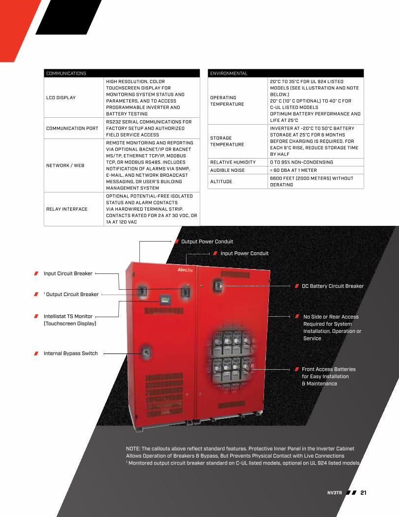
COMMUNICATIONS
LCD DISPLAY
HIGH RESOLUTION, COLOR TOUCHSCREEN DISPLAY FOR MONITORING SYSTEM STATUS AND PARAMETERS, AND TO ACCESS PROGRAMMABLE INVERTER AND BATTERY TESTING
COMMUNICATION PORTRS232 SERIAL COMMUNICATIONS FOR FACTORY SETUP AND AUTHORIZED FIELD SERVICE ACCESS
NETWORK / WEB
REMOTE MONITORING AND REPORTING VIA OPTIONAL BACNET/IP OR BACNET MS/TP, ETHERNET TCP/IP, MODBUS TCP, OR MODBUS RS485. INCLUDES NOTIFICATION OF ALARMS VIA SNMP, E-MAIL, AND NETWORK BROADCAST MESSAGING, OR USER’S BUILDING MANAGEMENT SYSTEM
RELAY INTERFACE
OPTIONAL POTENTIAL-FREE ISOLATED STATUS AND ALARM CONTACTS VIA HARDWIRED TERMINAL STRIP. CONTACTS RATED FOR 2A AT 30 VDC, OR 1A AT 120 VAC
ENVIRONMENTAL
OPERATING TEMPERATURE
20°C TO 35°C FOR UL 924 LISTED MODELS (SEE ILLUSTRATION AND NOTE BELOW.)20° C (10° C OPTIONAL) TO 40° C FOR C-UL LISTED MODELS OPTIMUM BATTERY PERFORMANCE AND LIFE AT 25°C
STORAGE TEMPERATURE
INVERTER AT -20°C TO 50°C BATTERY STORAGE AT 25°C FOR 6 MONTHS BEFORE CHARGING IS REQUIRED. FOR EACH 9°C RISE, REDUCE STORAGE TIME BY HALF
RELATIVE HUMIDITY 0 TO 95% NON-CONDENSING
AUDIBLE NOISE < 60 DBA AT 1 METER
ALTITUDE6600 FEET (2000 METERS) WITHOUT DERATING
Input Circuit Breaker
1 Output Circuit Breaker
Intellistat TS Monitor(Touchscreen Display)
Internal Bypass Switch
Input Power Conduit
DC Battery Circuit Breaker
Front Access Batteries for Easy Installation & Maintenance
Output Power Conduit
No Side or Rear Access Required for System Installation, Operation or Service
NOTE: The callouts above reflect standard features. Protective Inner Panel in the Inverter Cabinet Allows Operation of Breakers & Bypass, But Prevents Physical Contact with Live Connections1 Monitored output circuit breaker standard on C-UL listed models, optional on UL 924 listed models.
21NV3TR

BATTERY RUN TIMES
All UL 924 models listed as Emergency Lighting Equipment are provided with a standard 90 minute of battery backup. C-UL models are provided with a standard 30 minutes backup. Please consult factory for other C-UL listed run times. Optional run times include 15, 30, 60, 120, and 240 minutes at full rated load. When optional run times are provided, the emergency lighting inverter is UL 924 listed as “Auxiliary Lighting and Power Equipment”. Please consult factory for battery option weights and cabinet configurations.
MAINTENANCE BYPASS
On systems in which the nominal input and output voltages are the same, an optional external, wall-mounted, push-to-turn, 4 pole Break-Before-Make (BBM) or Make-Before-Break (MBB) wrap around maintenance bypass switch is available. In bypass mode, the switch bypasses the system allowing isolation of the inverter’s input and output, and to enable the inverter to be fully serviced (including the complete maintenance and replacement of circuit cards or components). The bypass switch includes an auxiliary contact to indicate the position of the switch (normal or bypass) for remote monitoring purposes.
The MBB bypass switch has a second auxiliary contact which is wired to the inverter system. This contact enables the switch’s push-to-turn function to invoke the static bypass before the switch is turned to the bypass position. With the static bypass engaged, no interruption of power to the load will occur during transfers and retransfers.
OUTPUT DISTRIBUTION
Provided in a side-mounted, 14” wide, front access distribution cabinet, a total of 12 pole positions per phase (36 total) are available to accommodate 1, 2, and 3 pole circuit breakers fed from an inverter system output of 208/120 VAC or 480/277 VAC. These circuit breakers are located behind a secured, lockable, hinged door; and can be factory-wired to the “Normally ON” bus and/or “Normally OFF” bus in any combination specified.
Monitored output circuit breakers are available, reducing the number of pole positions to 8 per phase (24 total). If a circuit breaker is open, the Intellistat TS monitor sounds an alarm. Optional alarm relay contacts are also available.
NORMALLY OFF BUS
Provides standby power to “normally OFF” emergency lights when utility power is lost or inadequate, or if energized via a remote alarm contact. This option includes:
• User-Programmable Settings• Transfer On Delay (0 – 8 seconds)• Transfer Off Delay (0 – 15 minutes)• Soft Start Control (0 – 172 cycles)• Remote Input “Command ON”• Allows a remote alarm contact signal
to energize the “Normally OFF” bus, thus illuminating the “Normally OFF” emergency lights.
STATUS/ALARM RELAY CONTACTS
Isolated, potential free (Form C) relay contacts, rated for 2A at 30 VDC or 1A 120 VAC, are available via a terminal strip for customers’ hardwired connections to building monitoring and security systems. Status/alarm contacts include inverter ON, ON battery power, low battery, general alarm, in bypass, periodic or annual test activated, output circuit breaker open, battery test pass, and battery test fail.
REMOTE COMMUNICATIONS
The NV3TR’s Intellistat TS monitor is available with optional NetMinder communications. NetMinder integrates the NV3TR into a BACnet/IP or BACnet MS/TP, Ethernet TCP/IP, MODBUS TCP, or MODBUS RS485 network with a specific IP address for Ethernet connected systems. NetMinder provides remote monitoring of the inverter status, battery test pass/fail results, alarm conditions, and electrical measurements via a web browser, without the need for any external software. Remote notification of alarms and status are available via SNMP, e-mail, and network broadcast messaging, or the user’s building management system.
INVERTER OPTIONS
22 NV3TR

NetMinder
Circuit Breakers
Normally OFF Bus Location
1 Note: Only 4 sub-main output breakers available on 40-55kW models.
23NV3TR

1. Stated full load BTU’s for 480/277 VAC input – output models. Consult factory for BTU’s of other models.
TYPICAL 3 PHASE INVERTER SCHEMATIC
SERIES RUNTIME (MINUTES)
INPUTVOLTAGE
CAPACITYOUTPUTVOLTAGE
MONITOROUTPUT DISTRIBUTION
RELAY INTERFACE OPTIONS
NV3TR30NV3TR60NV3TR90NV3TR120
BA KE SH
208/120V480/277V600/347V
101314151617202224
262830323340455055
BAKE SH
208/120V480/277V600/347V
0 - INTELLISTATINTELLISTAT WITH 1 - TCP/IP OR MODBUS TCP2 - MODBUS RS 4853 - BACNET/IP4 - BACNET MD/TP
0 - INTERGRAL MAIN CB ONLY 1 - DISTRIBUTION CABINET2 - DISTRI-
BUTION CABINET W/ NORMALLY OFF BUS
0 - NONE PROVIDED 1 - OUTPUT ALARM RELAY CONTACTS
AND OFF BUS “COMMAND ON” AND REPO INPUTS
2 - OFF BUS “COMMAND ON” AND REPO INPUTS
KVA/KW “BTU/HOUR FULL LOAD” 101314151617202224262830323340455055
3410443347745115545657976820750281848866954810230109121125319086214832387026257
ORDERING GUIDE
VOLTAGE CONFIGURATIONS INPUT OUTPUT VAC 60HZ
BABA - 208/120 - 208/120KEBA - 480/277 - 208/120SHBA - 600/347 - 208/120
BAKE - 208/120 - 480/277KEKE - 480/277 - 480/277SHKE - 600/347 - 480/277
BASH - 208/120 - 600/347KESH - 480/277 - 600/347SHSH - 600/347 - 600/347
Contact AimLite for single line drawings that include the external bypass switch scheme.
24 NV3TR

EBST-MVTNORMALLY OFF120V
GN
D
CONTROL INPUT
NEU
T12
0V
CONNECT 120VACLIGHTING CIRCUIT
12VBATTERY
(-) (+)
(-)
(+)
INVERTERGND
RJ12REMOTEPANEL
RED
WIR
E
12V
CHA
RGER
(-) BAT
(+) BAT
(-) L2(-) L1
(+) L2(+) L1
10 AWG BLACK
10 AWG REDTRA40109/CSATRANSFORMER
RED
120V BLACK
NEUTRAL WHITE
18 A
WG
GRE
EN
WHI
TE
BLA
CK
18 AWG GREEN
HAR028
FUSE80A-300V-T
HAR671FUSE HOLDER
4 AWG BLUE
4 A
WG
RED
4 A
WG
RED
HAR134
WHI
TE
GND NEUTRAL 120VAC
LOADS
GREEN
WHI
TE
BLA
CK
HAR028
HAR028-JUMPER
WHITE
# 18 AWG
(FOR TI OPTION)
R362K Ω½W
WHITE
BLACK
WHITE
GFCI TRIPINDICATOR
I
BLACK
M N
(-) (+)SHUNT
WIR
118-
BU
WIR
118-
GY
BOO
ST
25" YELLOW WIR118-YL
LAM
P RE
LAY
WIR
118-
RD
WIR
118-
BK
20" WIR118-WH
1
1
CONTROLLER BOARD
320W
500WCONTROLLER BOARD
26 EBST-MVT

12/9/2016 12:19:12 PM f=0.90 T:\Engineering\Projects\Project AB In process\PR-15018_Inverters at 900W and 1440W from Xantrex\04 Concept, design, proto T\Electrical design\1000W Battery Unit Preliminary Design\Drawings\1000W OFF\DWG-WD-0143-REV0-20161202.sch (Sheet: 1/1)
These wires must be of the same length These wires must be
of the same length
1N5819-B1N4004
30 ohm 10W
D1D2
13
6 4
9 7
AB
D4
R1
1
A
B
C
D
E
F
A
B
C
D
E
F
1 2 3 4 5 6 7 8 9
2 3
4 5 6 7 8 9 10 11 12 13 14 15
16 1718 29 30 3228 33 35
C
NCNO
coil
K1ELC-RL-12DC20ADPDT
21 222527394142
19 20 23 24 26 31 34
INVERTERREMOTEPANEL
TRA40109/CSA
HAR778-FUSE-BLOCK(32031T)
FUSE175A-300V-T
TRA40109/CSA
BA
T(-
)
BA
T(-
)
BA
T(+
)
BA
T(+
)
LA
MP
(+)
LA
MP
(+)
LA
MP
(-)
LA
MP
(-)
GND 120VNEUTRAL
LOADS
GND
CBD431-INV1440-CAL
TB1TB2TB3TB4TB5
WIR118-BU
WIR118-GY
WIR118-RD
WIR118-BK
WIR118-YL
WIR
118-W
HB
OO
ST
RE
LA
Y
SH
UN
T(+
)
SH
UN
T(-
)
CAL
1 1 1 11
BO
OS
T
BO
OS
T
CB
D12V
360-I
NV
500
CB
D12V
360-I
NV
500
ELC-INV-SW2000
ELC-INV-SW600-REMO
BATERY UNIT WITH 1000W INVERTER NORMALLY OFF
IPL
IPL
IPL
0GN
D
120V
NE
UT
RA
L
CONTROL INPUT
FAN
WIR
118-W
H
WIR118-VT
WIR112-BK
WIR112-RD
WIR
118-B
K
WIR118-RD
WIR118-BU
WIR118-BK
WIR118-BK
WIR118-RDWIR118-RD
B1 B2
B4
WIR118-BK
WIR118-WH
B5
WIR
135-B
U-1
6IN
WIR
136-R
D-1
6IN
BATPM12-55
BATPM12-55
T175A
/300V
SHUNT 200A/50mVELC-SHUNT-200A
12/9/2016 12:25:52 PM f=0.90 T:\Engineering\Projects\Project AB In process\PR-15018_Inverters at 900W and 1440W from Xantrex\04 Concept, design, proto T\Electrical design\1000W Battery Unit Preliminary Design\Drawings\1440W OFF\DWG-WD-0142-REV0-20161202.sch (Sheet: 1/1)
These wires must be of the same length
These wires must be of the same length
1N5819-B1N4004
30 ohm 10W
D1D2 D3
13
6 4
9 7
AB
D4
R1
1
A
B
C
D
E
F
A
B
C
D
E
F
1 2 3 4 5 6 7 8 9
2 3
4 5 6 7 8 9 10 11 12 13 14 15
16 17 18 19 20 29 30 31 3228 33 34 35
C
NCNO
coil
K1ELC-RL-12DC20ADPDT
21 2225262739404142
23 24 36 37 38 43 44
INVERTERREMOTEPANEL
TRA40109/CSA
HAR778-FUSE-BLOCK(32031T)
FUSE175A-300V-T
TRA40109/CSA
BA
T(-
)
BA
T(-
)
BA
T(+
)
BA
T(+
)
LA
MP
(+)
LA
MP
(+)
LA
MP
(-)
LA
MP
(-)
GND 120VNEUTRAL
LOADS
GND
CBD431-INV1440-CAL
TB1TB2TB3TB4TB5
WIR118-BU
WIR118-GY
WIR118-RD
WIR118-BK
WIR118-YL
WIR
118-W
HB
OO
ST
RE
LA
Y
SH
UN
T(+
)
SH
UN
T(-
)
CAL
1 1 1 11
BO
OS
T
BO
OS
T
CB
D12V
360-I
NV
500
CB
D12V
360-I
NV
500
ELC-INV-SW2000
ELC-INV-SW600-REMO
BATERY UNIT WITH 1440W INVERTER NORMALLY OFF
IPL
IPL
IPL
0
TRA40109/CSA
BA
T(-
)B
AT
(+)
LA
MP
(+)
LA
MP
(-)
BO
OS
T
CB
D12V
360-I
NV
500
IPL
GN
D
120V
NE
UT
RA
L
CONTROL INPUT
FAN
WIR
118-W
H
WIR118-VT
WIR112-BK
WIR112-RD
WIR
118-B
K
WIR118-RD
WIR118-BU
WIR118-BKWIR118-BK
WIR118-RDWIR118-RD
B1 B2
B3 B4
HAR134
B5
WIR
135-B
U-1
6IN
WIR
136-R
D-1
6IN
BATPM12-55
BATPM12-55
BATPM12-55
T175A
/300V
SHUNT 200A/50mVELC-SHUNT-200A
1000W
1440W
27EBST-MVT

RELAY DIAGRAM
28 RELAY DIAGRAM

aim_inverter_en_R03