MINI AIRSHIP PATROL CRAFT - National University of...
75
Department of Mechanical Engineering MINI AIRSHIP PATROL CRAFT In partial fulfilment to the requirements for the Degree of Bachelor of Engineering Session 2003/04 National University of Singapore Submitted by NG KAY BOON U006270J11
Transcript of MINI AIRSHIP PATROL CRAFT - National University of...

M
Department of Mechanical Engineering
INI AIRSHIP PATROL CRAFT
In partial fulfilment to the requirements for the
Degree of Bachelor of Engineering
Session 2003/04
National University of Singapore
Submitted by
NG KAY BOON
U006270J11

Summary
SUMMARY
This paper covers the basic idea behind the design of an airship. It covers three
phases of design: conceptual, preliminary, detailed. The purpose is to look into the
potential development of airship in the field of UAV. This project seeks to
design, build and test a mini airship for patrol and surveillance in build-up areas.
To develop an airship as an UAV to handle the task of patrolling and surveillance,
there is a need to justify the purpose of this project as investment of cash is
involved. This paper will discuss on the justification of this project.
This design taps on the usage of vectored thrusting to propel the airship. This
design has the capability of performing vertical take-off. The lifting gas, helium,
which provides lift due to the differential in density, compensates the weight of
the airship. A take-off or landing roll is not necessary for this design.
Calculations and estimations of performance values were done. Three flight tests
were conducted to verify the results. Discrepancy is mainly due to the assumption
of negligible skin frictional drag and negligible drag force is sustained by the
gondola and tail fins. The theoretical calculation was based on form drag. The
actual results show the design is capable of performing slow speed manoeuvring.
Table 1A: Airship Performance
Performance Cruise Speed (m/s) Rate of Climb (m/s) Rate of Turn (deg/s)
Theoretical 1.22 0.66 32.5
Experimental 0.85 0.50 28.6
% Difference 30.3% 24.2% 12.0%
National University of Singapore Department of Mechanical Engineering
i

Summary
Flight tests (2 indoor, 5 outdoor) were conducted to quantify the airship in
performing a surveillance role. For indoor flights, manoeuvrability and
controllability are excellent. The outdoor flights proved otherwise as performance
is affected by weather conditions. The relationship between the range (direct line
of sight) of airship and the smallest observable object at that range is established.
The area surveyed is also related to the range. The longer the range the larger is
the area coverage and it is more difficult to spot a small object on the screen.
This project has demonstrated the potential of an UAV airship performing military
roles. However, there is always a limitation to every design. Weather conditions
have always been the nemesis of airships. Special considerations have to be taken
note of. This is beyond the scope of this paper.
Figure 1A: Prototype of airship designed
Tail Fin MotorEmpennage
Gondola Airship UAV
National University of Singapore Department of Mechanical Engineering
ii

Acknowledgements
ACKNOWLEDGEMENTS
The author will like to express his heartfelt gratitude towards his supervisor, Dr
Gerard Leng S. B. for his guidance and counsel during the course of the project.
The author will also like to extend his gratitude to the staff of Dynamics
Laboratory for their assistance for the duration of the project.
Assistance from the peers during the trial runs is deeply appreciated. Special
thanks go to Mr Esmond Chua Boon How, Miss Ng Xin Ying, Miss Coleen Ng
Wee Hoon, Miss Melody Yang Shu Fang and Mr Chee Tze Seng Simon for their
aids during flight-testing phase.
National University of Singapore Department of Mechanical Engineering
iii
Table of Contents
TABLE OF CONTENTS
SUMMARY.................................................................................................. i
ACKNOWLEDGEMENTS ..........................................................................iii
TABLE OF CONTENTS.............................................................................iii
LIST OF FIGURES ....................................................................................vi
LIST OF TABLES.......................................................................................ix
LIST OF SYMBOL ..................................................................................... x
1. Introduction ....................................................................................... 1
1.1. Objectives ...................................................................................... 2
1.2. Organisation of thesis .................................................................... 3
2. Conceptual Design............................................................................ 4
2.1. Justification of project development ............................................... 4
2.2. Potential roles of airship UAV ........................................................ 5
2.3. Criteria for operation of blimp......................................................... 5
2.4. Drafting of Airship design ............................................................... 6
2.4.1. Airship category ....................................................................... 6
2.4.2. Main components of the blimp ................................................. 6
2.4.3. Structural category and shape of the gas envelope. ................ 7
2.4.4. Shape of Gondola .................................................................... 8
2.4.5. Propulsion System and Surveillance System........................... 8
2.4.6. Empennage (Tail fins stabilizers) ............................................. 9
2.4.7. Conceptual Drawings ............................................................... 9
National University of Singapore Department of Mechanical Engineering
iii

Table of Contents
3. Preliminary Design.......................................................................... 10
3.1. Propulsion System Evaluation ..................................................... 10
3.1.1. Streamlining motor holders .................................................... 10
3.1.2. Determination of thrust force by propulsion system ............... 11
3.1.3. Variable line of thrust ............................................................. 11
3.2. Estimation of payload................................................................... 12
3.3. Dimension of envelope................................................................. 13
3.4. Center of buoyancy and center of mass....................................... 14
3.5. Performance of the airship ........................................................... 15
3.5.1. Maximum cruise speed .......................................................... 15
3.5.2. Maximum rate of climb ........................................................... 16
3.5.3. Maximum rate of turn ............................................................. 17
3.5.4. Maximum altitude................................................................... 18
4. Detailed Design............................................................................... 20
4.1. Construction of prototype ............................................................. 20
4.1.1. Gondola ................................................................................. 20
4.1.2. Empennage............................................................................ 24
4.2. Flight test ..................................................................................... 26
4.3. Evaluation and quantification of prototype. .................................. 28
4.3.1. Quantification of prototype ..................................................... 28
4.3.2. Evaluation of prototype .......................................................... 32
5. Conclusions .................................................................................... 34
6. Recommendations .......................................................................... 36
References .............................................................................................. 38
National University of Singapore Department of Mechanical Engineering
iv

Table of Contents
Appendix A: Equipment data sheet.......................................................... 39
Appendix B: Selection of airship category................................................ 43
Appendix C: Selection of envelope shape ............................................... 46
Appendix D: Material Selection for gas envelope..................................... 47
Appendix E: Specifications of motor ........................................................ 50
Appendix F: Modification of motor holders............................................... 51
Appendix G: Thrust force determination .................................................. 53
Appendix H: Length to depth ratio of envelope ........................................ 55
Appendix I: Lifting Gas............................................................................. 57
Appendix J: Center of buoyancy & center of mass .................................. 58
Appendix K: Calculation of volume and area ........................................... 59
Appendix L: Aerostatics ........................................................................... 61
Appendix M: Scope of video camera ....................................................... 63
National University of Singapore Department of Mechanical Engineering
v
List of Figures
LIST OF FIGURES
1A Prototype of airship designed
2A Shape of gondola
2B Streamlined shape of the envelope
2C Arrangement of tail fins
2D Gondola and motors position
3A Motor holders
3B Mechanism for varying line of thrust
3C Variable line of thrust
3D Governing equation of shape profile of envelope
3E Projected area for different flight configuration
3F Graph of drag force experience by airship Vs velocity of airship
3G Resolving vectors for line of propulsion (Side View)
3H Graph of drag on airship Vs velocity of airship
3I Yaw motion
3J Graph of drag force Vs rate of turn
3K Graph of ρnet, for a range of Off-Standard conditions Vs altitude
4A Dimension of gondola casing
4B Positions of holes to be drilled
4C Installation of ball bearings to reduce friction
4D Installation of carbon fibre rod
4E Circuit diagram of console
4F Mounting of surveillance
4G Dimensions of the tail fins
National University of Singapore Department of Mechanical Engineering
vi

List of Figures
4H Engineering drawing of mini patrol airship
4I Experimental setup for tabulating resolutions.
4J Image taken at different flight altitudes
4K Graph of image dimension
4L Graph of range (m) Vs dimension(m)
4M Scope of wireless video camera
4N Road surveillance
6A 50ft UAV airship
A1 Micro speed controller
A2 Futaba receiver
A3 Micro servo S3107
A4 FM transmitter
A5 Wireless Video Camera
A6 voltage regulator circuit diagram
A7 Lithium Cell
A8 Setup for real time image transmission
B1 Structural category
C1 Graph of envelope area to sphere for same volume Vs len. to dep. ratio.
D1 Datasheet of Mylar
D2 Datasheet of Polyurethane
F1 Motor holders
F2 Experimental setup
F3 Graph of thrust force Vs voltage
G1 Graph of force Vs change in length of spring
National University of Singapore Department of Mechanical Engineering
vii

List of Figures
G2 Experimental setup for determination of thrust force
G3 Graph of thrust force Vs supply voltage
K1 Governing equation of shape profile of envelope
K2 Volume tabulation
K3 Tabulation of surface area of the streamline profile
K4 Projected area for different flight configuration
M1 Experimental setup for determining scope
National University of Singapore Department of Mechanical Engineering
viii

List of Tables
LIST OF TABLES
1A Airship performance
3A Weight tabulation of airship components
4A Experimental data of image resolution.
B1 Airship categories
B2 Assessment of the suitable of the 3 airship design concepts to military
performance.
B3 Description of structural category of airships
F1 Experimental data of thrust force with varying voltage
H1 Variation of drag of bodies of revolution of constant volume with
thickness ratio.
I1 Comparison of lifting gas
L1 International Standard Atmospheric conditions at sea-level
M1 Tabulation of results for scope angles
National University of Singapore Department of Mechanical Engineering
ix

List of Symbols
LIST OF SYMBOL
T Propulsive thrust force, N
Ftensile Tensile spring force, N
Fdrag Drag force
Flift Lift force
CD Coefficient of drag
CL Coefficient of lift
v Velocity, m/s
A Surface area
k Elastic spring constant
Lnet Net static lift, kg
VT Total gas volume of envelope, m3
ρnet Net lift density, kg/ m3
ρair Air density, kg/ m3
l Maximum length of the airship, m
d Maximum diameter of the airship, m
R Range (direct distance between target and airship), m
OD Dimension of the smallest observable target on screen, m
θh Horizontal scope angle
θv Vertical scope angle
dh Horizontal scope distance
dv Vertical scope distance
National University of Singapore Department of Mechanical Engineering
x

Chapter 1 - Introduction
1. Introduction
This paper will look into the conceptualization, implementation and validation of
the potential role that mini patrol airship may undertake in the near future,
especially so in military applications.
The history of airship dated back to 1783, when the Montgolfier sent up the first
hot air balloon. Inventors began refining the design into steerable airships. The
next lap occurred in the 1900s, when Count Ferdinand von Zeppelin developed
the rigid airships. These airships fulfilled their military roles in both World Wars.
Besides being used for military purposes such as patrolling, hunting submarines
and escorting convoys, flying radar stations for coastal defense system, airships
were also developed for commercial purposes. Its heyday period was ended in
1937 when the most famous airship, Hindenburg (804 ft in length, 135 ft in its
largest diameter, cruising altitude of 650 ft, reaching a speed of 80 miles per
hour), crashed in a disaster in an attempt to land. Triggered by the economic
downturn, the development of airship came to a standstill.
In today’s context, where technology is available, Unmanned Aerial Vehicles
(UAVs), are given the spotlight. UAVs have proved their capability in the recent
conflicts such as Iraq (2003), Afghanistan (2001) and Kosovo (1999). Till date
most of the UAVs developed are either fixed or rotary wings. This project seeks
to develop the potential role of an airship as an UAV in military application. The
main purpose is in the arena of surveillance.
National University of Singapore Department of Mechanical Engineering
1

Chapter 1 - Introduction
1.1. Objectives
The main objective of this project is to design, build and test a mini airship for
patrol base, observation post in build up areas. The basic minimum function of
the blimp is to send back real time data (graphics) to the operator on ground. The
designed blimp is to function as an UAV. This project will also evaluate on other
possible applications of the blimp.
The project will be broken down into 3 phases:
• Conceptual Design
i. Justifying the need to develop this project.
ii. Define the potential role of the airship functioning as an UAV
iii. Setting the criteria for the operation of the airship.
iv. Draft out the design of the airship.
• Preliminary Design
i. Propulsion System Evaluation
ii. Estimation of payload
iii. Dimension of envelope
iv. Determination of center of buoyancy and center of mass.
v. Performance of the airship.
National University of Singapore Department of Mechanical Engineering
2
Chapter 1 - Introduction
• Detailed Design
i. Assembling of components
ii. Flight tests
iii. Quantifying the prototype.
1.2. Organisation of thesis
The thesis is composed of six chapters. Chapter 1 introduces the project and
defines the objectives of the project. Chapter 2 deals with the initial conceptual
phase of design. Chapter 3 described the development of the preliminary design
phase. Chapter 4 handles the last phase of design, detailed design. Detailed
design includes test flights and the quantifying of prototype. Chapter 5 will
concludes this thesis. Chapter 6 will discuss on the relevant recommendations.
National University of Singapore Department of Mechanical Engineering
3

Chapter 2 – Conceptual Design
2. Conceptual Design
In this phase of the design, it will touch on justifying the needs to develop this
project, identifying the potential roles of the project blimp, setting the operation
criteria and drafting out the design of the blimp.
2.1. Justification of project development
With the current technology, development of UAVs, is made possible. UAVs are
cheaper to procure and they reduce the risk to pilot’s life. They can assume
missions normally reserved for manned aircraft. UAVs played an important role
in the recent conflict between U.S. and Iraq. They played the role of surveillance,
transmitting data and images back to the operator, providing the U.S. army with
upfront information of the enemy’s frontline. With this technology, it is possible
to revive the airships as UAVs to perform military roles as its large counterpart
has done in the past.
Emphasis has been placed on developing fixed and rotary wings UAVs. In
Singapore, Singapore Technology has successfully developed Fantail UAV
(rotary wing) and Multi-role UAV (fixed wing), for the purpose of military
reconnaissance. Currently in the Republic of Singapore Air Force, only one fixed
wing UAV is in operation, IAI Searcher. The current development has its
disadvantages. In the event of a crash landing or air accidents, the sophisticated
equipment on board is irretrievable. To launch and land the fixed wing UAVs, a
large area is required. To develop an airship as an UAV is viable. Airships
accidents are no longer fatal with the used of helium as the lifting gas. When the
gasbag is puncture or in the event of engine failure, the airship will loss its lift and
National University of Singapore Department of Mechanical Engineering
4

Chapter 2 – Conceptual Design
starts descending gradually. The main components will still be retrievable.
Moreover, with vertical take off and landing (VTOL) capability, it does not
require a large space for launching and landing.
With the increasing threat from terrorists, there is a need to source on all potential
methods to survey buildings, especially where Singapore is an urban forest.
Airship UAV is another potential source besides the Fantail UAV.
2.2. Potential roles of airship UAV
i. Surveillance of building interior.
ii. Surveillance around build up areas. (patrol base, observation post)
iii. Mine seeking device
iv. Sending lethal payloads to enemy’s frontline.
This project will focus on developing the second potential.
2.3. Criteria for operation of airship
i. Low altitude operation
ii. Basic maneuvering capability (Climb, Descend, Fore, Aft, Yaw).
iii. Slow speed handling
iv. Handle payload of 20% of the total weight of the blimp components.
v. Bear the load of a wireless video camera with visual capability of 300m
unobstructed.
vi. Provides over-the next-building and around-the-corner perspective.
vii. Simplicity and low cost operation.
National University of Singapore Department of Mechanical Engineering
5

Chapter 2 – Conceptual Design
2.4. Drafting of Airship design
This section of the thesis will cover the approach on designing of the UAV
airship.
2.4.1. Airship category
Based on the classification of the performance of airships, Category B type of
performance is selected for this design. This category of airship is widely known
as the “Vectored Thrust” airships. (Appendix B)
i. It has the modest degree of complication. It means that 100% of the lift
force is provided by the lifting gas. Aerodynamic lift does not contribute to
generating the lift force during operation.
ii. It overcomes low speed controllability to large extent.
iii. It provides a variable propulsion thrust line.
iv. Vectored thrust permits zero roll at take-off and landing.
2.4.2. Main components of the blimp
i. Gasbag (Envelope)
ii. Gondola (Console casing)
iii. Propulsion system
c
iv. Surveillance system
v. Power source
vi. Empennage (Tail fins stabilize
National University of Singapore Department of Mechanical Engineering
To be housed in the sameasing known as Gondola
rs)
6

Chapter 2 – Conceptual Design
2.4.3. Structural category and shape of the gas envelope.
Structural Category
Considering all factors, the non-rigid structure is chosen for the gas envelope.
With this non-rigid structure, it is known as the pressure airship. The pressure of
the lifting gas within maintains the hull profile. No rigid structure is attached to
distribute the payload. (Appendix B)
Shape of gas envelope
The shape of the envelope has a major influence on its overall performance.
Envelope weight is proportional to surface area and lift is proportional to the
volume. In an ideal case, the surface area should be as small as possible relative
to the volume. Air resistance is also determined primarily by the surface area. A
spherical shape provides optimum lift efficiency. Any deviation from this
optimum should utilized shapes based on circular arc sections to minimize surface
stress. From the comparison results in Appendix C, the conventional streamlined
shape is selected. It is the most efficient shape for an immersed body moving
through a fluid.
National University of Singapore Department of Mechanical Engineering
7

Chapter 2 – Conceptual Design
2.4.4. Shape of Gondola
The shape must be of a streamline body as such drag is reduced. It must not have
sharp corners or rough surface. This is to reduce both flow separation (results in
wake or turbulence formed, increasing the drag force) and skin friction drag. It
must be able to house all the components. To meet the criteria, Model A is
selected as the gondola for the airship.
D
CBA
Figure 2A: Shape of gondola
2.4.5. Propulsion System and Surveillance System
Propulsion System
The maneuverability of the airship depends solely on vectored thrusting. To
fulfill the operation criteria, this design will require a minimum of three motors
fixed with propellers. To allow reverse thrusting, 6-9 propellers are fixed to the
rotating shaft of the motors. The line of thrust must be variable to produce the
pitching motion.
Surveillance System
Wireless video camera with a built-in transmitter is to be installed into the system.
The direct line of sight must be variable. It is to have a visual capability of 300m
unobstructed.
National University of Singapore Department of Mechanical Engineering
8

Chapter 2 – Conceptual Design
2.4.6. Empennage (Tail fins stabilizers)
The bare hull of streamline form is directionally unstable, tending always to turn
broadside on to the direction of motion. Tail fins are required to ensure the
stability of the airship. They also act as flow straighteners, arranged in a cross
configuration. Control surfaces (elevators, rudders) will not be installed on the
tail fins, as they are not required to generate a pitching moment. Moving at a slow
speed will also render the control surfaces ineffective.
2.4.7. Conceptual Drawings
Figure 2C: Arrangement of tail fins
Figure 2D: Gondola and motors position
Motor Holder
6-9 Propeller
Variable Line of Thrust
Gondola
Figure 2B: Streamlined shape of the envelope
National University of Singapore Department of Mechanical Engineering
9

Chapter 3 – Preliminary Design
3. Preliminary Design
This phase of the design process will deal with working on the selection,
specifications and limitations of the airship.
3.1. Propulsion System Evaluation
In the design, the airship has two motors, one on each side, connected through a
movable axle, that can tilt up or down. These motors will control the pitching
motions, forward and reverse motions of the airship. The third motor is fixed to
the lower vertical tail fin and it controls the yawing motion of the airship. Since
this design is highly dependent on vectored thrusting for controllability, it is
important to determine the maximum amount of thrust that the propulsion system
can produced. From which, the performance of the airship can be determined.
Mabuchi N20 motors are used for the system (Refer to Appendix E for motor
specifications).
3.1.1. Streamlining motor holders
The motor holders will support the motors. From the experiment conducted
(Appendix F), it is advantageous to streamline the holders. The amount of thrust
force generated is larger by 0.40g with a 9% increased in the weight of the holder.
The small increase in weight does not contribute significantly to the total payload.
Figure 3A: Motor holders
Unmodified Motor Holder
Modified Motor Holder
National University of Singapore Department of Mechanical Engineering
10

Chapter 3 – Preliminary Design
3.1.2. Determination of thrust force generated by propulsion system
The same method is employed to determine the thrust force (Appendix F). To
verify the experimental results, a more conventional method is used. In this
method an extension spring, of spring constant k = 1.983, is used to determine the
thrust force generated by the motor with propeller fixed to it (Appendix G).
Although both methods produce similar results, the conventional method is more
accurate. It gives the direct relation between the thrust force and tensile force
experience by the spring.
xkFT tensile ∆==
3.1.3. Variable line of thrust
The variable line of thrust will enable the airship to perform climbing and
descending motion. When the line of thrust remains horizontal, it allows the
airship to propel forward or backward, depending on the direction of thrust.
Figure 3B: Mechanism for varying line of thrust
Propeller 20T
10T Plastic Spur Gears Gear Ratio – 2 : 1
Futaba Micro Servo
N20 Motor
National University of Singapore Department of Mechanical Engineering
11

Chapter 3 – Preliminary Design
Figure 3C: Variable line of thrust
-80°
+80°
Horizontal Line of Thrust
The line of thrust varies from -80° to +80°. The setting of back thrust and with a
line of thrust set at +70° will set the airship into a climb. The signal for the
configuration is sent via a remote controller.
3.2. Estimation of payload
It is difficult to calculate the actual overall weight of the airship. An estimation of
payload is important as it will determine the volume of lifting gas required and
hence, the size of the airship. It will also affects the performance of the airship.
To account for the weight of the envelope material, an estimate of 100% of the
total weight of components is added. Another 10% is added to account for the
eventual changes or improvements and additions to the airship.
)84.242%(10)84.242%(10084.242 ++= Total Estimated Weight
= 500g
National University of Singapore Department of Mechanical Engineering
12

Chapter 3 – Preliminary Design
Table 3A: Weight tabulation of airship components
Components Weight (g)
3 x Mabuchi N20 Motors 15.3
3 x 6-9 propellers (Diameter = 0.08m) 2
3 x Motor holders 7.74
Futaba Micro Servo (S3107) 9
Futaba 4 channels Micro Receiver 11.3
Receiver Battery (NiCd 4.8V) 95.6
Micro Speed Controller, Wires, Switch 12.5
Wireless Video Camera 15.1
Energizer 9V battery 36
Carbon Fibre Rod with Pinion Gear 6.3
Driver Gear 1.1
Tail Fins (Empennage Stabilizers) 12.7
Gondola (polyvinyl chloride) 18.2
Total 242.84
3.3. Dimension of envelope
12
2
2
2
=+by
ax 1
2 2
2
2
2
=+by
ax
Figure 3D: Governing equation of shape profile of envelope
1.404a
2b
a
National University of Singapore Department of Mechanical Engineering
13

Chapter 3 – Preliminary Design
With the knowledge of the estimated weight of the airship, the dimension of the
envelope can be derived. The governing equation of the shape profile is shown in
Figure 3D. The length to maximum depth ratio of 2.27 is chosen (Appendix H).
At sea-level under ISA condition,
kgVL netTnet 5.0== ρ
347.0169.0225.1
5.0 mVT =−
=
32 )53.0)(609.1()609.1( aabVT ππ ==
ma 7.0=
37.053.0 == ab
mal 7.1404.2 ==
mbd 75.02 ==
The purchased envelope is made of polyurethane (vinyl) and has a dimension of
1.7m in length and maximum diameter (depth) of 0.75m. The capacity of the
envelope when fully inflated is 0.50m3.
3.4. Center of buoyancy and center of mass
There is a need to determine the center of buoyancy and the center of gravity of
the envelope. So that it will aid in ensuring the stability of the blimp at a later
stage of construction. To determine the center of buoyancy, the centroid of the
shape of the envelope must be determined. The volume of air displaced is exactly
the volume occupied by the shape of the envelope. By finding the centroid of the
envelope shape, it is equivalent of finding the center of buoyancy. From
Appendix J, the position of the center of buoyancy is 0.817m from the head of the
National University of Singapore Department of Mechanical Engineering
14

Chapter 3 – Preliminary Design
airship and it lies on the line of revolution. The envelope is made of homogenous
material, the center of mass will coincide with the center of buoyancy.
3.5. Performance of the airship
After all the components have been determined, the performance of the airship
will be of interest. Performance includes maximum speed, maximum rate of
climb, rate of turn, maximum flight altitude.
3.5.1. Maximum cruise speed
It is the maximum speed at which the airship is cruising at straight and level. The
drag force sustain by the airship is estimated with the following equation.
AvCF airDdrag2
21 ρ=
The coefficient of drag, CD is estimated to be 0.35 (A value between that of a
sphere - 0.39 and a streamline body - 0.05). The CD is achieved at a Reynolds
number of 104. From the graph in Figure 3E, with the maximum thrust achieved
by propulsion of two motors (0.14N) at 5 volts, the maximum theoretical speed
achievable is 1.22m/s. (Refer to Appendix K for calculation of projected area)
Figure 3E: Projected area for different flight configuration.
Projected area for climb, descend, turn
Projected area for straight and level
National University of Singapore Department of Mechanical Engineering
15

Chapter 3 – Preliminary Design
0.00000
0.05000
0.10000
0.15000
0.20000
0.25000
0.30000
0.35000
0.40000
0.000 0.500 1.000 1.500 2.000 2.500
Velocity of airship (m/s)
Dra
g Fo
rce
(N)
Max Thrust = 0.14 N Max Speed = 1.22 m/s
Figure 3F: Graph of drag force experience by airship Vs velocity of airship
3.5.2. Maximum rate of climb
It is the maximum rate at which the airship ascends. The line of thrust is resolved
into the vertical and horizontal components. Vertical component results in the lift
thrust. The CD value is estimated to be 5.2. Maximum value occurs at the line of
thrust of 80° with a rate of 0.66m/s.
0.138N 0.14N
80°
Figure 3G: Resolving vectors for line of propulsion (Side View)
National University of Singapore Department of Mechanical Engineering
16

Chapter 3 – Preliminary Design
0.00
0.05
0.10
0.15
0.20
0.25
0.30
0.00 0.20 0.40 0.60 0.80 1.00Velocity of airship (m/s)
Dra
g on
airs
hip
(N)
10 Deg20 Deg30 Deg40 Deg50 Deg60 Deg70 Deg80 Deg
Figure 3H: Graph of drag on airship Vs velocity of airship
Max Vertical th ° ofthMCl
rust at 80 linerust = 0.138 N ax Rate of imb = 0.66 m/s
Max. Vertical Thrust = 0.138N Max. Rate of climb = 0.66m/s
3.5.3. Maximum rate of turn
Only one motor is responsible for the yawing motion. The maximum thrust
available for turning at full power (5V) is 0.07N. The CD value is estimated to be
5.2. From the graph in Figure 3H, the maximum rate of turn is 32.5°/s.
dtdR
dtds θ
=C.G
R=0.817m 0.07N Thrust from motor fixed at bottom tail fin
Figure 3I: (Top view) Yaw motion
National University of Singapore Department of Mechanical Engineering
17

Chapter 3 – Preliminary Design
0.000.020.040.060.080.100.120.140.16
0 10 20 30 40 50
Rate of turn (Deg/s)
Dra
g f
orc
e (
N)
Figure 3J: Graph of drag force Vs rate of turn
0.18
60
Max Thrust = 0.07N Max. rate of turn = 32.5°/s
3.5.4. Maximum altitude
From the manufacturer specifications, the airship can withstand an expansion of
10% of the total volume.
322 503.0)375.0)(707.0()609.1(609.1 mabVT === ππ
3' 553.0)1.1( mVV TT ==
To avoid unnecessary stress on the envelope material, the airship should not
exceed the altitude where the volume of the airship has increased to 0.553m3.
Using the equation, netTnet VL ρ=
The net lift density, ρnet, can be determined with net static lift, Lnet, remaining
constant. 3
3' /904.0553.0
5.0 mkgm
kgVL
T
netnet ===ρ
National University of Singapore Department of Mechanical Engineering
18

Chapter 3 – Preliminary Design
Hence, ρnet cannot exceed 0.904kg/m3. A chart of relative density for a range of
Off-Standard conditions against altitude is plotted to determine the maximum
altitude achievable without over stressing the envelope material.
0.00
0.50
1.00
1.50
2.00
2.50
0.00 0.20 0.40 0.60 0.80 1.00 1.20 1.40
Lift Density (kg / cubic meter)
Flig
ht A
ltitu
de (k
m)
ISA -35ISA -30ISA -25ISA -20ISA -15ISA -10ISA -5ISAISA +5ISA +10ISA +15ISA +20ISA +25ISA +30ISA +35Limiting Lift Density
Figure 3K: Graph of net lift density, for a range of Off-Standard conditions Vs altitude
From the graph above, at ISA +15, the maximum altitude the airship can achieve
is 1000m above sea level. Beyond which the envelope may over expand and
causes a failure in the material. (Refer to Appendix L for detail calculation)
However there is a limitation to the maximum altitude. Futaba 6XAs 6-channel
remote control system is used for transmission of signals. The maximum
transmission range stated by the manufacturer is 100m unobstructed. Hence, the
maximum altitude is more affected by the radio transmission range rather than by
the limiting net lift density.
National University of Singapore Department of Mechanical Engineering
19

Chapter 4 – Detailed Design
4. Detailed Design
Construction of the prototype will be the next phase of the design process. This is
followed by indoor and outdoor flight tests. The chapter will end with evaluation
and quantification of the prototype built.
4.1. Construction of prototype
The envelope is purchased off-shelf. The minimum dimensions are derived
before purchasing (Section 3.3., Appendix H). Emphasis is placed on constructing
the gondola and the empennage (tail fins).
4.1.1. Gondola
The gondola (Figure 4A) houses the propulsion system, surveillance system,
power source and radio signal receiver. The main positions to be fixed are the
holes as shown in Figure 4B. The equipments are installed in the following order;
a) Ball bearings and carbon fibre rods (Figure 4C & 4D).
b) Motors fitted with 6-9 propellers
c) Radio signal receiver, servo, micro controller.
d) Surveillance system (Figure 4E).
The 4.8V NiCd battery (powers propulsion system) and 9V alkaline battery
(powers surveillance system) are replaced by a 8.4V lithium polymer cell. To
protect the micro controller, a voltage regulator circuit is installed to step down
the power voltage to 5V before feeding into the micro controller circuit. The
wireless video camera continues to be powered by the 8.4V lithium polymer cell.
National University of Singapore Department of Mechanical Engineering
20

Chapter 4 – Detailed Design
Department of Mechanical Engineering
Front View
Figure 4A: Dimension of Gondola Casing
0.065m
0.115m
0.150m
Top View
Front View
Top View
0.150m
0.115m
0.040m
Figure 4B: Position of holes to be drilled
0.020m
∅4.5mm
0.025m
∅9mm 0.025m
National University of Singapore 21

Chapter 4 – Detailed Design
Figure 4C Installation of ball bearings to reduce friction
Tamiya Guide Roller Ball Bearings
Figure 4D: Installation of carbon fibre rod.
Pinion gear attached to rod
0.36m
Figure 4E: Circuit diagram of console
Controls Line of Thrust
Futaba Servo
Variable Thrust Line Propeller Motors
Tail Fin Propeller Motor
5V Speed Controller
Voltage Regulator
Video Camera
Switch
Lithium Battery 8.4V
Futaba 4 Ch Receiver
CH1 CH4 CH3CH2
National University of Singapore Department of Mechanical Engineering
22

Chapter 4 – Detailed Design
Figure 4F: Mounting of surveillance system
3
2 1
3
2
1
Wireless Video Camera
Adjustable Joint To vary line of sight
Balsa wood 0.02m
0.015m
0.03m
Carbon fibre rod
Gondola Casing
National University of Singapore Department of Mechanical Engineering
23

Chapter 4 – Detailed Design
4.1.2. Empennage
The tail fins are made of balsa wood with a thickness of 2mm. The fins are
arranged in a cross configuration. A propeller motor will be installed on the lower
vertical tail fin, will control the yaw motion of the airship.
24
Horizontal tail fins, upper vertical tail fin
0.17m 34° 0.105m 0.16m Lower vertical tail fin 0.17m 34° 0.02m ∅80mm 0.105m
0.14m 0.04m
Figure 4G: Dimensions of the tail fins
National University of Singapore Department of Mechanical Engineering

Chapter 4 – Detailed Design
Figure 4H: Engineering drawing of mini patrol airship
Top View
Front View Right View
Isometric View
National University of Singapore Department of Mechanical Engineering
25

Chapter 4 – Detailed Design
4.2. Flight test
Flight tests are conducted indoor and outdoor. The objective of indoor flight test
is for testing of the airship manoeuvrability. The results are excellent for indoor
test. The airship is able to perform all manoeuvres as designed. During the test,
obstacles are set. The airship is able to overcome the barrier (simulating flying
over a building) and survey the surrounding (objects place beyond the barrier). It
has also shown its capability of performing around-corner flight.
Outdoor flight test prove to be more challenging than indoor. The operation of the
airship is susceptible to weather, especially wind. With the slightest breeze, it will
affect the controllability. Hence, most of the outdoor test flights are conducted in
the early hours of dawn when the weather is most calm. Under still air condition,
the airship is able to climb up to 30m smoothly. It has demonstrated its capability
of surveying the surrounding of a building and over-fly a building to survey a
stretch of road.
In both scenarios, the main difficulty is getting the survey objects to be in focus
(clarity of the objects). Before hand the operator must have knowledge of the
range to be survey and set the focusing of the video camera before operating the
airship for surveillance.
Flight tests were also done to verify the theoretical performance tabulated in
Section 3.5. For cruise speed and rate of climb, the airship was flown for a
known distance and height. The time was note down for the journey. The
procedure was repeated 5 times and the average was taken. For cruise speed it
National University of Singapore Department of Mechanical Engineering
26

Chapter 4 – Detailed Design
was found to be 0.85m/s. For the rate of climb it was 0.5m/s. In determining the
rate of turn, the airship was made to complete five 360° turns. Time was noted for
this manoeuvre. The test was repeated 5 times and the average taken was 28.6°/s.
The discrepancies between the experimental and theoretical results are due to
human errors (parallax and reaction error). However, a large fraction of the
difference is due to the estimation made during theoretical calculations. Due to
limited resources, test could not be conducted at wind tunnel to determine the CD
value for the whole airship. Secondly, projected area is used instead of the wetted
surface area. Hence the value obtain is more known as form drag. Skin friction
drag was not included in the calculation. The percentage difference for cruise,
climb and turn are 30.3%, 24.2% and 12% respectively.
The experimental results obtained are accepted for the operation of airship at low
speed. Since it is required to perform surveillance, it is not necessary for the
airship to move at high speed.
National University of Singapore Department of Mechanical Engineering
27

Chapter 4 – Detailed Design
4.3. Evaluation and quantification of prototype.
To quantify the prototype as a UAV surveillance airship, the resolution of the
image transmitted back to ground operator need to be determined. With the
resolution known, the user can foresee the smallest object that can be detected at a
specific range. If the dimension of the object to be survey is known, the flight
altitude of the airship can be controlled such that the object remains detectable at
the operating flight altitude.
4.3.1. Quantification of prototype
An experiment was carried out to determine the relationship between range and
smallest observable object on an LCD screen (Image resolution is set at 320 x 240
ppi).
Figure 4I: Experimental setup for tabulating resolution
Target
Horizontal distance
fixed at 14m
Flight Altitude
Range
National University of Singapore Department of Mechanical Engineering
28

Chapter 4 – Detailed Design
Targets
Figure 4J: Image taken at various flight altitudes
22.5m
9.0m
18.0m
13.5m4.5m
Table 4A: Experimental data of image resolution
Flight Altitude (m) 4.500 9.000 13.500 18.000 22.500 Range (m) 14.705 16.643 19.449 22.804 26.500
Dimension of object on LCD screen (m) Original dimension (m)
Resolution = 320 x 240 ppi 0.100 0 0 0 0 0 0.200 0.002 0.001 0.0005 0 0 0.300 0.003 0.002 0.001 0.0005 0 0.400 0.004 0.003 0.002 0.001 0.0005 0.500 0.005 0.004 0.003 0.002 0.001 0.600 0.006 0.005 0.004 0.003 0.002 0.700 0.007 0.006 0.005 0.004 0.003 0.800 0.008 0.007 0.006 0.005 0.004 0.900 0.009 0.008 0.007 0.006 0.005
National University of Singapore Department of Mechanical Engineering
29

Chapter 4 – Detailed Design
0.00
10.00
20.00
30.00
40.00
50.00
60.00
0 0.001 0.002 0.003 0.004 0.005 0.006 0.007 0.008 0.009 0.01
Image dimension on LCD screen (m)
Rang
e (m
)
0.2m0.3m0.4m0.5m0.6m0.7m0.8m0.9m
Actual object dimension
Figure 4K: Graph of image dimension Vs range
From the graph plot in Figure 4J, it is observed the image resolution reduces to
0.0005m before becoming invisible to the naked eye. The dimension of
magnitude of 0.0005m is used as a benchmark to indicate the smallest object that
may be viewed or transmitted back to the operation ground. Hence, at a range of
19.45m the smallest observable image has an actual length magnitude of 0.2m.
nge
(m
y = 39.813x + 10.883
0.00
5.00
10.00
15.00
20.00
25.00
30.00
35.00
40.00
45.00
50.00
0 0.1 0.2 0.3 0.4 0.5 0.6 0.7 0.8 0.9 1
Smallest object dimension (m)
Ra
)
Figure 4L: Graph of range (m) Vs dimension of object (m)
National University of Singapore Department of Mechanical Engineering
30
Chapter 4 – Detailed Design
From Figure 4K, the relation of range and the smallest object observable from the
screen is established.
9.10)8.39( += DOR
For example, the body length of a car is about 4m. The airship must be within the
range of 170m for the car to be detected in the LCD screen.
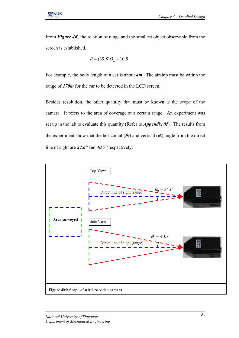
Besides resolution, the other quantity that must be known is the scope of the
camera. It refers to the area of coverage at a certain range. An experiment was
set up in the lab to evaluate this quantity (Refer to Appendix M). The results from
the experiment show that the horizontal (θh) and vertical (θv) angle from the direct
line of sight are 24.6° and 40.7° respectively.
Figure 4M: Scope of wireless video camera
Area surveyed Side View
Top View
θv = 40.7° Direct line of sight (range)
θh = 24.6° Direct line of sight (range)
National University of Singapore Department of Mechanical Engineering
31

Chapter 4 – Detailed Design
For example, at a range of 20m,
( )( )( )275.15
7.40tan6.24tan202m=
=tantan2R vh= θθ Area surveyed
4.3.2. Evaluation of prototype
Airship UAV has advantages over fixed wing and rotary UAVs. Fixed wing
aircraft cannot hover over a target and rotary wings UAV have sever vibration
problems for camera use and have a limited payload. The airship is able to
resolve the problems in one vehicle. A loss in control or motor failure means
damage to the aircraft and to the expensive onboard equipment (e.g. camera), is
almost guaranteed. In contrast, airship is not immediately placed into jeopardy by
the loss of control. If subjected to heavy landing, the shock absorbing nature of
the envelope protects the equipment against impact. If power is lost, the airship
will descend slowly being only slightly heavy.
On the other hand, the envelope fabric is prone to damage is repeatedly inflated
and deflated. Hence, to prolong the lifespan of the envelope, it is kept inflated. It
will take up a lot of storage spaces. Secondly, the airship is extremely susceptible
to weather conditions. Camera tasks can be difficult to achieve in breezy
conditions.
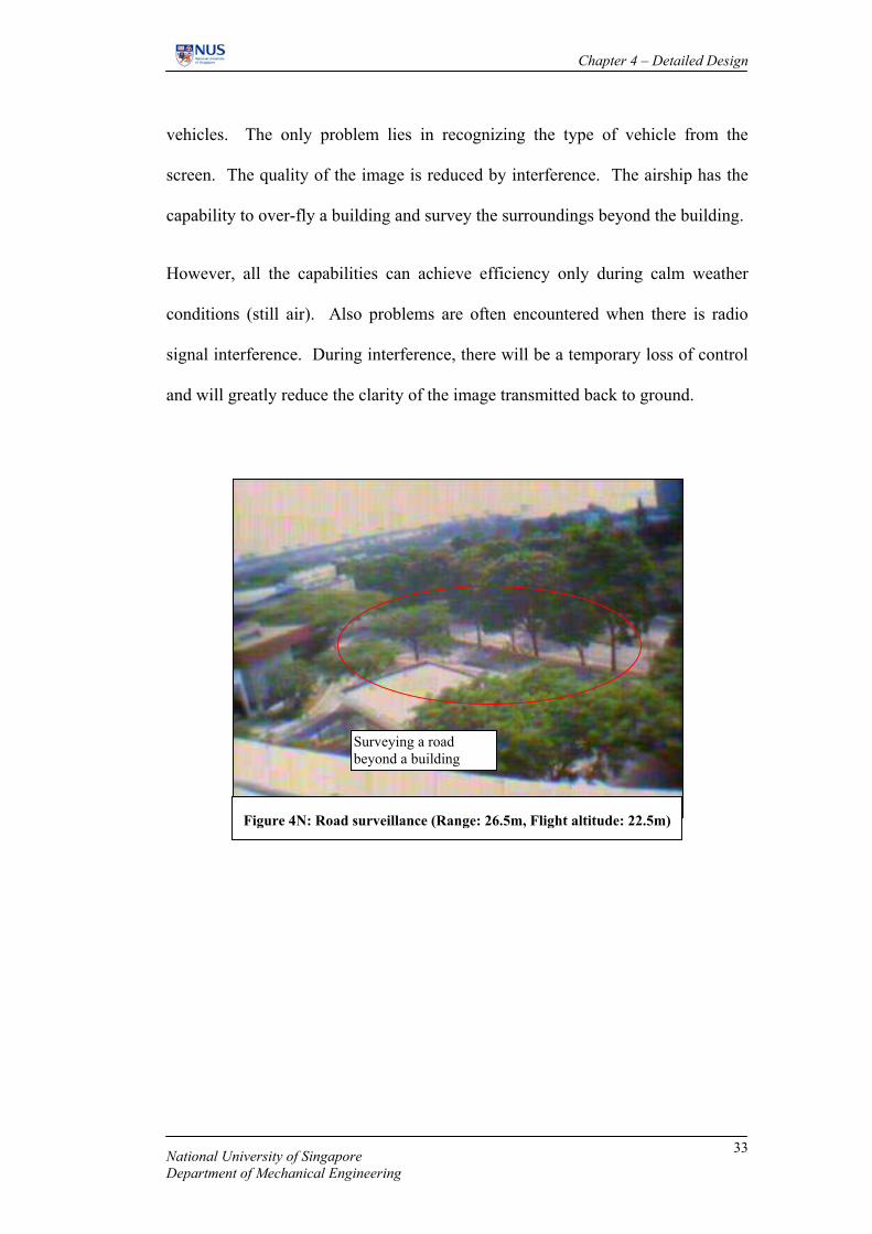
With the surveillance system, the airship provides a birds’ eye view of the
surrounding. It provides a good perception of the surveyed area. It allows the
operator on the ground to detect moving vehicles based on the real-time image
transmission (Figure 4N). From the results, it shows that is it possible to detect
National University of Singapore Department of Mechanical Engineering
32
Chapter 4 – Detailed Design
vehicles. The only problem lies in recognizing the type of vehicle from the
screen. The quality of the image is reduced by interference. The airship has the
capability to over-fly a building and survey the surroundings beyond the building.
However, all the capabilities can achieve efficiency only during calm weather
conditions (still air). Also problems are often encountered when there is radio
signal interference. During interference, there will be a temporary loss of control
and will greatly reduce the clarity of the image transmitted back to ground.
Figure 4N: Road surveillance (Range: 26.5m, Flight altitude: 22.5m)
Surveying a road beyond a building
National University of Singapore Department of Mechanical Engineering
33
Chapter 5 – Conclusions
5. Conclusions
The objectives of this project have been met. An airship is designed with the
intention of operating it as an UAV. Flight tests carried out during the course of
the project have shown that the airship designed is capable of performing the
manoeuvres as stated in the criteria of the conceptual design phase. The airship
has the VTOL (Vertical Take-Off and Landing) capability. The airship is able to
perform patrolling task around build-up area with the aid of a string tie-down to it.
With a maximum thrust of 0.14N, the airship has a cruise speed of 0.85m/s and a
rate of climb of 0.50m/s. With the operation of the tail fin motor (thrust of 0.07N),
it gives a rate of turn of 28.6°/s. The performance is suitable for slow speed
operation required for surveillance. However, there exists a barrier to counter the
weather effects. This accounts for the aid of a tie-down string during operation.
The airship design is incapable of countering the effects of wind.
With the relationship established experimentally, given the range, the area
coverage under the surveillance system can be estimated. The smallest object that
can be detected on the image transmitted to the screen can also be determined.
For example, at the flight altitude of 22.5m (height of 5 storey building) with a
range of 26.5m, area coverage is 20.87m2. It is possible to survey a stretch of
road and the vehicles can be easily spotted from the screen, as the smallest
possible object to be detected on the screen is 0.4m.
Despite the failure to perform efficiently under outdoor conditions, the ideas
brought across are that developing the airship into an UAV has immense
National University of Singapore Department of Mechanical Engineering
34

Chapter 5 – Conclusions
potential, especially in the military field of application. As discussed in Section
4.3.2. that airship has advantages in terms of operation cost as compared to fixed
and rotary wing aircraft. Airships are not susceptible to fatal crashes as that
experience by fixed wing aircrafts.
The theoretical values calculated are based on ISA conditions and the effects of
wind and superheat are not taken into account. In actual operating conditions,
these effects do play a part in affecting the performance of the airship. However,
these tabulated values are good estimates of the performance of the airship.
National University of Singapore Department of Mechanical Engineering
35

Chapter 6 – Recommendations
6. Recommendations
During the course of the project a form of contradiction has developed. On one
hand, the project has shown the capability of the airship in military operation. It
is therefore more advantageous than using a fixed wing aircraft. On the other,
military task is referred to as a tactical mission. Hence, the “mini” airship
designed may be too big for it to be stealthy and tactical; especially it is designed
to operate at low altitude. The current designed dimension has difficulty in
countering weather conditions. A smaller physical dimension will make it worse
unless a strong and powerful motor powers it. However, to install these motors,
meant an increase in net static weight, the net static lift must also increase to meet
the demand, which will result in an increase in volume (therefore a respective
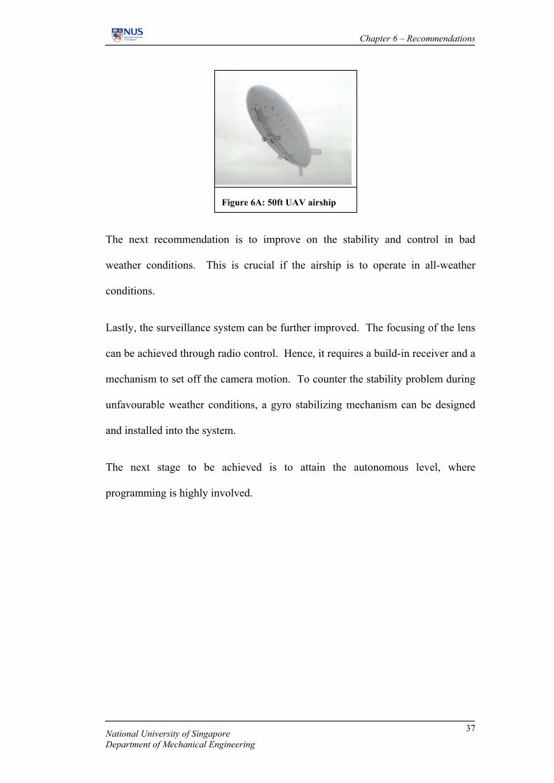
increase in dimension). A recommendation for this issue is to fully develop an
airship large enough (50ft in length) to bear the load of two powerful motors with
the capability of countering weather effects (e.g. counter a headwind of 20knots).
With these capabilities, the airship is capable of attaining a cruise altitude of
4000ft. A 50ft airship at 4000ft will be very difficult to spot. The actual
dimension of a manned airship can easily hit 300ft in length. 50ft is only 1/6 of
the 300ft so in this context is it still considered “mini”. However, the money
invested will be increased by about 20 times the amount spends in this project
($1300).
National University of Singapore Department of Mechanical Engineering
36
Chapter 6 – Recommendations
Figure 6A: 50ft UAV airship
The next recommendation is to improve on the stability and control in bad
weather conditions. This is crucial if the airship is to operate in all-weather
conditions.
Lastly, the surveillance system can be further improved. The focusing of the lens
can be achieved through radio control. Hence, it requires a build-in receiver and a
mechanism to set off the camera motion. To counter the stability problem during
unfavourable weather conditions, a gyro stabilizing mechanism can be designed
and installed into the system.
The next stage to be achieved is to attain the autonomous level, where
programming is highly involved.
National University of Singapore Department of Mechanical Engineering
37

References
References
1. Gabriel A. Khoury, and J. David Gillett., “Airship Technology,”
Cambridge University Press, United Kingdom, 2000
2. Vittorio Gregotti, “Rassegna (Airships),” CIPIA, Italy, 1996
3. Erwin Kreyszig, “Advanced Engineering Mathematics,” John Wiley &
Sons, Singapore, 1999.
4. Edward L. Safford Jr., “Radio Control Manual,” Tab Books, U.S., 1979.
5. Edward L. Safford Jr , “Advanced Radio Control”, Tab Books, U.S., 1976.
6. Robert D. Blevins, “Applied fluid dynamics handbook”, Van Nostrand
Reinhold Co., New York, N.Y., 1984., pp. 279 – 375
7. Ferdinand P. Beer & E. Russell Johnston Jr., “Vector Mechanics for
Engineers, Statics”, McGraw-Hill Ryerson, 1998, pp. 250 -254
8. LT. COL Donald E. Ryan, Jr., “The Airship’s Potential For Intertheater
and Intratheater Airlift”, School of Advanced Airpower Studies, Air
University, United States Air Force, Maxwell Air Force Base, Alabama,
May 1992
National University of Singapore Department of Mechanical Engineering
38

Appendix A: Equipment data sheet
Appendix A: Equipment data sheet
Micro Speed Controller Figure A1: Micro Speed Controller
Specifications Data of Speed Controller
• Three channel throttle control
• Drive three motors proportionally forward or reverse up to 1 amp for 4.8V
• Weight: 6 grams
• Power source: 4 cell Nicad battery operation from 2.8 to 5.4 volt
• High frequency (2 khz) PWM
• High efficiency circuit for 99% transfer of power
• Power conservation software allows minuscule current draw with motors off or coasting
• Repeatable throttle and dead band performance
Futaba Micro Receiver R114F (4 Ch)
Specifications Data of Micro Receiver
4 Channels
Weight: 11.3 grams
Dimensions: 32 x 13 x 22mm
Frequency: 77MHz
Figure A2: Futaba Receiver
National University of Singapore Department of Mechanical Engineering
39

Appendix A: Equipment data sheet
Futaba Super Micro Servo S3107
National University of Singapore Department of Mechanical Engineering
40
Specifications Data of Micro Servo
Dimension: 21.8 x 11.0 x 19.8mm
Weight: 9 grams
Operating speed (4.8v): 0.12 sec
Output torque (4.8v): 1.2 kg.cm
Figure A3: Micro Servo S3107
Futaba 6XAS 6-Channel FM/PCM Transmitter
Specifications Data of Transmitter
Description: T6XAS PCM1024 Multifuction 6 channel transmitter may be used with any Futaba FM/PPM receiver. Works with Futaba PCM1024 receivers when the built-in PCMtransmission option is selected. The liquid-crystal display panel allows rapid data input into its easy-to-read LCD display. The T6XAS system comes complete with programming for ACRO (aircraft) and HELI (helicopter) mixing and can accommodate virtually any model configuration. The compact ergonomically designed transmitter holds completely independent memories for 6 DIFFERENT MODELS. This radio has a memory backup chip, which enables it to keep the radio settings when the transmitter battery is removed for cycling. This Futaba radio is diode protected to prevent overcharging, which means that the battery cannot be discharged through the transmitter.
Features:
• The stick length and tension are adjustable.
• Switches are provided for Dual rates (D/R), Programmable mixers (PMX)
• Programming features include servo reversing for all channels
• Dual Rates for all 3 channels
Figure A4: FM Transmitter

Appendix A: Equipment data sheet
Wireless Video Camera
Specifications Data of WVC
Dimension: 44x23x23mm
Weight: 19.3 grams
Output power: 10mW
Scan frequency: 50Hz Transmission distance: 50m-100m (Without blockage)
Figure A5: Wireless Video Camera
Voltage Regulator Circuit
Enables the wireless video camera and speed controller to share a common power
source. The lithium polymer cell has a voltage of 8.4V. The video camera taps
directly from the original source. The voltage regulator circuit is used the step
down the voltage to 5V before feeding it to the speed controller circuit.
Viewcam
ControllerC2
200uFC1
200uF
IN
COM
OUT
U178L05
+V
8.4V
Viewcam
Figure A6: Voltage regulator circuit diagram
Voltage Regulator
National University of Singapore Department of Mechanical Engineering
41
Appendix A: Equipment data sheet
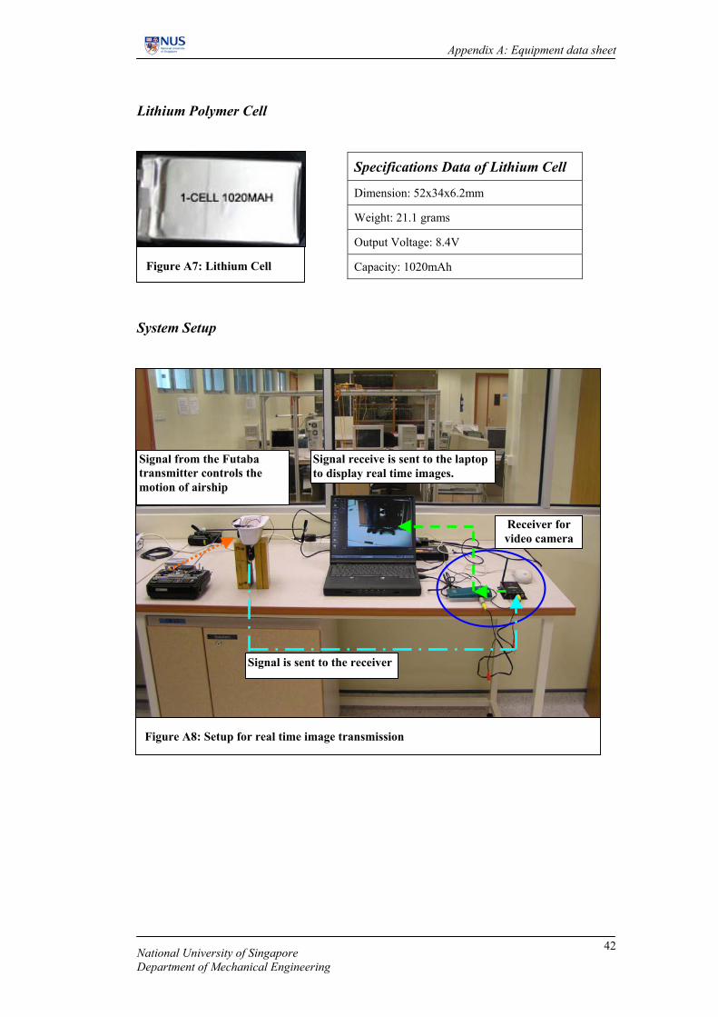
Lithium Polymer Cell
Specifications Data of Lithium Cell
Dimension: 52x34x6.2mm
Weight: 21.1 grams
Output Voltage: 8.4V
Capacity: 1020mAh
Figure A7: Lithium Cell
System Setup
Figure A8: Setup for real time image transmission
Signal from the Futaba transmitter controls the motion of airship
Signal is sent to the receiver
Signal receive is sent to the laptop to display real time images.
Receiver for video camera
National University of Singapore Department of Mechanical Engineering
42

Appendix B: Selection of airship category
Appendix B: Selection of airship category
A large variety of airship types can be postulated. The airship types are
categorized according to the degree of augmentation of the lifting gas static lift by
means of direct powered lift.
Table B1: Airship categories.
Airship Category Description
A • No lift augmentation
• Non-variable propulsion thrust line
• Uses aerodynamic control to incline body axis,
generating hull-lift using airspeed.
• Hull lift is used to supplement static gas lift to support
initial heaviness at take-off and landing.
• Requires ground roll to achieve take-off and landing.
B • Partial lift augmentation
• Modest degree of complication
• Overcomes low speed controllability
• Variable propulsion thrust line
C • Total lift augmentation
• High degree of complexity
• Support payload by power lift
National University of Singapore Department of Mechanical Engineering
43
Appendix B: Selection of airship category
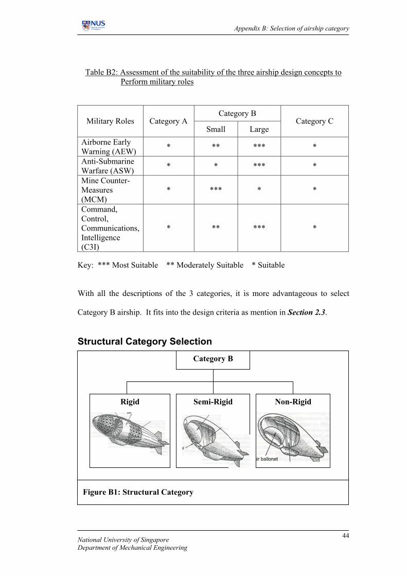
Table B2: Assessment of the suitability of the three airship design concepts to
Perform military roles
Category B Military Roles Category A
Small Large Category C
Airborne Early Warning (AEW) * ** *** *
Anti-Submarine Warfare (ASW) * * *** *
Mine Counter-Measures (MCM)
* *** * *
Command, Control, Communications, Intelligence (C3I)
* ** *** *
Key: *** Most Suitable ** Moderately Suitable * Suitable With all the descriptions of the 3 categories, it is more advantageous to select
Category B airship. It fits into the design criteria as mention in Section 2.3.
Structural Category Selection
Category B
Rigid Semi-Rigid Non-Rigid
Figure B1: Structural Category
National University of Singapore Department of Mechanical Engineering
44

Appendix B: Selection of airship category
Table B3: Description of structural category of airships. Structural Category Description
Rigid
• Carries external loading through a lightweight
structural outer shell.
• Shell is divided into many compartments each
housing a separate gasbag.
• Lifting-gas pressure is not required to maintain the
shape of airship.
• Allows a lower internal gas pressure as compared to
non-rigid airship.
Semi-Rigid • A long structural keel is installed to share the
bending load.
Non-Rigid
• No structural installation.
• Load is bear by the inflated gasbag.
• Hull profile is maintained by the lifting-gas
pressure.
Non-rigid type of airship is selected. The designed payload does not require a
metal structure for support. The strength of the gasbag material and the internal
overpressure is more than sufficient to sustain the payload. Adding a structural
support may enhance the stability but it also reduces the allowable payload.
National University of Singapore Department of Mechanical Engineering
45

Appendix C: Selection of envelope shape
Appendix C: Selection of envelope shape
0.0
0.5
1.0
1.5
2.0
2.5
3.0
3.5
4.0
4.5
5.0
0.000 2.000 4.000 6.000 8.000 10.000 12.000 14.000 16.000
Length/Depth Ratio
S.A
. Env
elop
e/S.
A. S
pher
e fo
r sam
e Vo
l.
Lenticular Streamlined
Lenticular
Streamlined
Figure C1: Graph of envelope area to sphere for same volume Vs length to depth ratio
Two types of shape are currently available in the market, conventional
streamlined shape and lenticular shape. From the plot above, lenticular shape
deviates the most from the optimum life efficiency (spherical shape). It is
difficult to compromise optimum lift and surface area (skin friction drag) for
lenticular shape. For streamlined shape, optimum lift as well as surface area is
compromised. Hence, streamlined shape is selected for this design.
National University of Singapore Department of Mechanical Engineering
46

Appendix D: Material selection for gas envelope
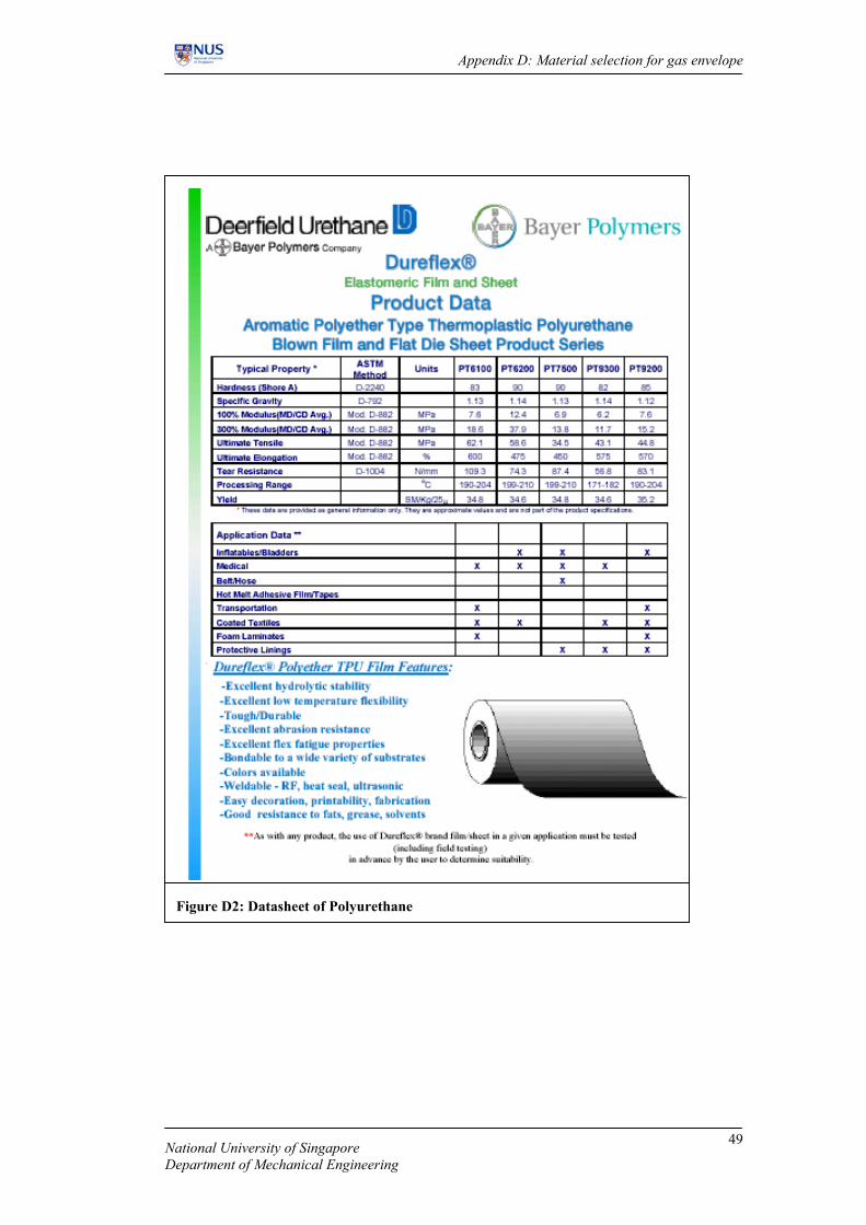
Appendix D: Material Selection for gas envelope
Two types of material are of interest in this project; mylar and polyurethane
(vinyl). The datasheet of the two materials are attached to this appendix. In
comparison, mylar is denser than polyurethane. Hence, polyurethane is more
applicable when payload is of concerned. Polyurethane has low helium
permeability (3% loss per day), good handling properties (more durable) and
crease resistance giving a professional look. Polyurethane also has good
weatherability. Polyurethane is more flexible than mylar as the material allows
10% expansion of the total volume. When punctured, the hole will propagate
rapidly in mylar whereas with polyurethane the hole does not propagate. The
advantage of mylar is that is it much cheaper than polyurethane reducing the cost
of the project. Polyurethane is chosen as the material for gas envelope.
National University of Singapore Department of Mechanical Engineering
47

Appendix D: Material selection for gas envelope
Figure D1: Datasheet of Mylar
National University of Singapore Department of Mechanical Engineering
48
Appendix D: Material selection for gas envelope
Figure D2: Datasheet of Polyurethane
National University of Singapore Department of Mechanical Engineering
49

Appendix E: Specifications of motor
Appendix E: Specifications of motor
National University of Singapore Department of Mechanical Engineering
50

Appendix F: Modification of motor holders
Appendix F: Modification of motor holders
Figure F1: Motor holders
Unmodified Motor Holder
Modified Motor Holder
Experiment objective: To determine if modifying the motor holder affects the
generation of thrust.
DC power
source Motor holder
Electronic Balance
Figure F2: Experimental setup
The setup of the experiment is as shown above and the distance between the
propeller and the electronic balance is fixed at 0.15m. The voltage of the power
source is varied to obtain the corresponding thrust force (measured in grams, read
off from the electronic balance).
National University of Singapore Department of Mechanical Engineering
51
Appendix F: Modification of motor holders
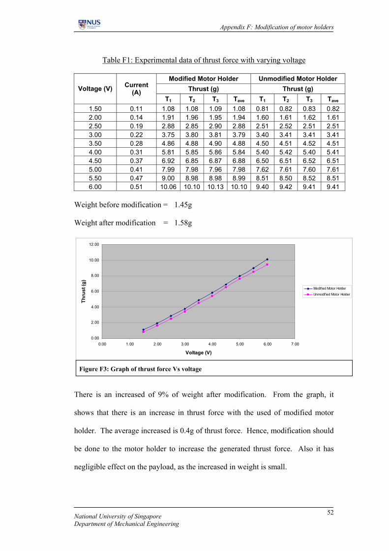
Table F1: Experimental data of thrust force with varying voltage
Modified Motor Holder Unmodified Motor Holder Thrust (g) Thrust (g) Voltage (V) Current
(A) T1 T2 T3 Tave T1 T2 T3 Tave
1.50 0.11 1.08 1.08 1.09 1.08 0.81 0.82 0.83 0.82 2.00 0.14 1.91 1.96 1.95 1.94 1.60 1.61 1.62 1.61 2.50 0.19 2.88 2.85 2.90 2.88 2.51 2.52 2.51 2.51 3.00 0.22 3.75 3.80 3.81 3.79 3.40 3.41 3.41 3.41 3.50 0.28 4.86 4.88 4.90 4.88 4.50 4.51 4.52 4.51 4.00 0.31 5.81 5.85 5.86 5.84 5.40 5.42 5.40 5.41 4.50 0.37 6.92 6.85 6.87 6.88 6.50 6.51 6.52 6.51 5.00 0.41 7.99 7.98 7.96 7.98 7.62 7.61 7.60 7.61 5.50 0.47 9.00 8.98 8.98 8.99 8.51 8.50 8.52 8.51 6.00 0.51 10.06 10.10 10.13 10.10 9.40 9.42 9.41 9.41
Weight before modification = 1.45g Weight after modification = 1.58g
0.00
2.00
4.00
6.00
8.00
10.00
12.00
0.00 1.00 2.00 3.00 4.00 5.00 6.00 7.00
Voltage (V)
Thru
st (g
)
Modif ied Motor Holder
Unmodif ied Motor Holder
Figure F3: Graph of thrust force Vs voltage
There is an increased of 9% of weight after modification. From the graph, it
shows that there is an increase in thrust force with the used of modified motor
holder. The average increased is 0.4g of thrust force. Hence, modification should
be done to the motor holder to increase the generated thrust force. Also it has
negligible effect on the payload, as the increased in weight is small.
National University of Singapore Department of Mechanical Engineering
52

Appendix G: Thrust force determination
Appendix G: Thrust force determination
Experimental objective: To determine the thrust force generated by Mabuchi
N20 motor fixed with 6-9 propeller.
The spring constant, k, of the spring used in this experiment is determined. Spring force equation: xkFtensile ∆=
0
0.1
0.2
0.3
0.4
0.5
0.6
0.004 0.015 0.033 0.057 0.081 0.107 0.134 0.162 0.19 0.217
Change in length (m)
Forc
e (N
)
∆
Figure G1: Graph of force (N) Vs change in length of spring
F = 1.983 x
With the knowledge of k value, the thrust force generated by the motor will be
determined. The experimental setup is as shown in Figure G2.
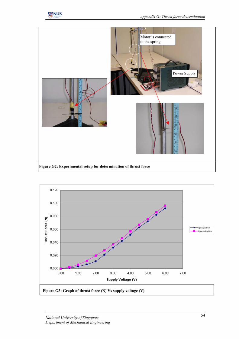
The data is collected and plotted on a graph (Figure G3). From the graph the
thrust force produced by one motor at a supply voltage of 5V is 0.072 N.
National University of Singapore Department of Mechanical Engineering
53
Appendix G: Thrust force determination
National University of Singapore Department of Mechanical Engineering
54
Motor is connected to the spring
Power Supply
Figure G2: Experimental setup for determination of thrust force
0.000
0.020
0.040
0.060
0.080
0.100
0.120
0.00 1.00 2.00 3.00 4.00 5.00 6.00 7.00
Supply Voltage (V)
Thru
st F
orce
(N)
Spr ing Method
Balance Machine
Figure G3: Graph of thrust force (N) Vs supply voltage (V)
Appendix H: Length to depth ratio of envelope
Appendix H: Length to depth ratio of envelope
Av
FC
air
dragD 25.0 ρ
=Av
FC
air
liftL 25.0 ρ
=
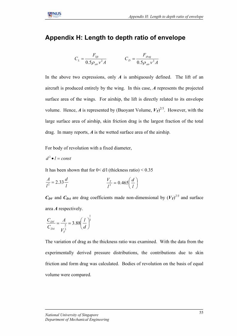
In the above two expressions, only A is ambiguously defined. The lift of an
aircraft is produced entirely by the wing. In this case, A represents the projected
surface area of the wings. For airship, the lift is directly related to its envelope
volume. Hence, A is represented by (Buoyant Volume, VT)2/3. However, with the
large surface area of airship, skin friction drag is the largest fraction of the total
drag. In many reports, A is the wetted surface area of the airship.
For body of revolution with a fixed diameter,
constld =•2
It has been shown that for 0< d/l (thickness ratio) < 0.35
ld
lA 33.22 =
=
ld
lVT 465.03
CDV and CDA are drag coefficients made non-dimensional by (VT)2/3 and surface
area A respectively.
31
32 88.3
==
dl
V
ACC
TDA
DV
The variation of drag as the thickness ratio was examined. With the data from the
experimentally derived pressure distributions, the contributions due to skin
friction and form drag was calculated. Bodies of revolution on the basis of equal
volume were compared.
National University of Singapore Department of Mechanical Engineering
55

Appendix H: Length to depth ratio of envelope
Table H1: Variation of drag of bodies of revolution of constant volume with
thickness ratio (REF 1).
d/l A/l2 Reynold’s No. x 107 CDA CDV
0.05 0.114 2.360 0.00271 0.0285
0.10 0.229 1.491 0.00301 0.0251
0.15 0.342 1.138 0.00329 0.0240
0.182 0.413 1.000 0.00347 0.0237
0.20 0.456 0.940 0.00356 0.0236
0.25 0.570 0.810 0.00386 0.0237
0.30 0.692 0.716 0.00422 0.0244 From the table above, CDA increases with d/l whereas CDV has a minimum. Young
suggest that the minimum occurs at d/l = 0.182. An appropriate value from the
table is d/l = 0.2. This minimum indicates the airship must be very flat and with
this ratio, it will incur a small drag penalty compared with the optimum.
However, in the design, low drag is only one of the factors in optimising a design.
The other point of consideration is that increasing the ratio thickness can reduce
the structural bending moments.
Giving considerations to both factors, the thickness ratio is fixed to be between
0.4 to 0.5. With reference to Figure C1, thickness ratio of 0.45 (Fineness ratio =
2.2) does not cause a tremendous increase in surface area as compared to the
optimum. With the estimation of payload, the volume of lifting gas is estimated
which gives the volume of gas envelope when fully inflated. Selection of the gas
envelope is based on these values. The gas envelope purchased has a fineness
ratio of 2.27 (thickness ratio = 0.44).
National University of Singapore Department of Mechanical Engineering
56

Appendix I: Lifting Gas
Appendix I: Lifting Gas
Helium is selected as the lifting gas for this design. Despite the cost, it is the most
efficient source of static lift for the airship and that it is safe as it is an inert gas.
Table I1: Comparison of lifting gases
Gas Density (kg/m3)
Lifting Force (N/m3) Comment
Hydrogen 0.085 11.2 Inflammable, relatively cheap
Helium 0.169 10.2 Inert, relatively expensive
Hot Air 0.906 3.14 Inert, very cheap, relatively poor lift
Methane 0.756 4.5 Inflammable, relatively cheap
Helium gas does not come in pure form. To account for the impurity, the density
is with the following formula. Helium gas purchased for this experiment has a
purity of 99.999%. Hence, the density of helium is approximated to 0.169kg/m3.
( ) )225.11169.0( ×−+×= kkHeρ
k =Percentage purity of helium
National University of Singapore Department of Mechanical Engineering
57

Appendix J: Center of buoyancy & center of mass
Appendix J: Center of buoyancy & center of mass
Archimedes Principle: Magnitude of the buoyant force acting on the body is equal
to the weight of the fluid displaced by the body. Buoyant force passes through the
centroid (center of buoyancy) of the displaced volume.
dxrdV 2π=
∫= dVxVx elrs
22
xxel =r
∫=993.0
0
222 dxrxVx πs
∫
−=
993.0
0
22
2
22 21 dxb
axxVx πs
1104.022 =Vxs
12
2
2
2
=+by
ax
12 2
2
2
2
=+by
ax
∫−
=0
707.0
211 dxrxVx πs
∫−
−=
0
707.0
22
3
11 dxbaxxVx πs
0552.011 −=Vxs
z
z
x
y
-0.707
Note: y2 = r2
0.993
dx
xa
z
x
y
For composite body,
VxVX ∑ ∑=rr
1104.0)0552.0()50.0( +−=X mX 11.0=
National University of Singapore Department of Mechanical Engineering
58

Appendix K: Calculation of volume, surface area, projected area
Appendix K: Calculation of volume, surface area, projected area
12
2
2
2
=+by
ax 1
2 2
2
2
2
=+by
ax
V2, S2V1, S1
y
x
Figure K1: Governing equation of shape profile of envelope
1.404a
2b
a
The streamlined shape profile selected for this design is a composite shape. It
consists of an ellipsoid and a modified ellipsoid. X-axis, is the axis of symmetry
and the axis of revolution.
12
2
2
2
=+by
ax
2
222
abxby −=
∫ −=a
dxabxbV
02
222
1 π
21 3
2 abV π=
12 2
2
2
2
=+by
ax
2
222
2abxby −=
∫ −=a
dxabxbV
404.1
02
222
2 2π
22 943.0 abV π=
221 609.1 abVVVT π=+=
Figure K2: Volume tabulation
Volume Tabulation
National University of Singapore Department of Mechanical Engineering
59
Appendix K: Calculation of volume, surface area, projected area
National University of Singapore Department of Mechanical Engineering
60
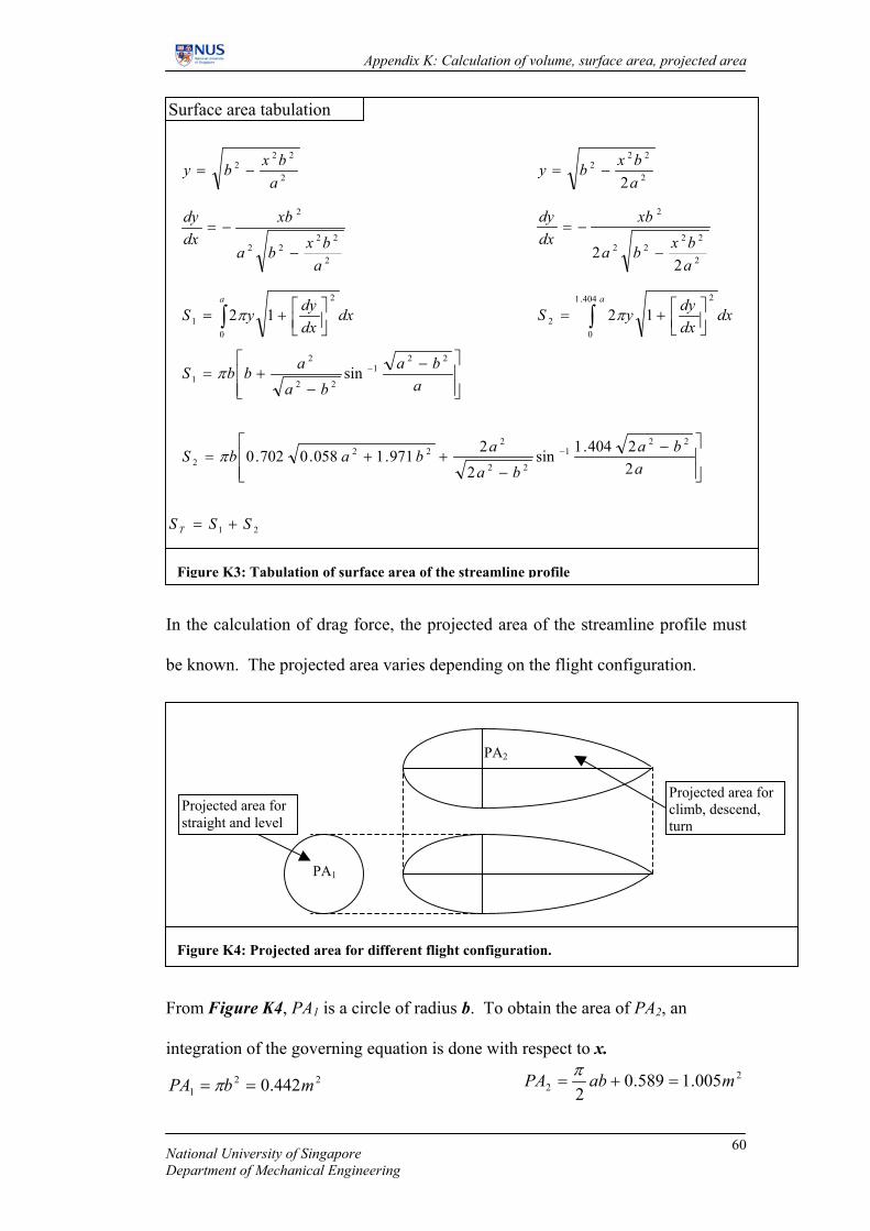
221 442.0 mbPA == π
22 005.1589.0
2mabPA =+=
π
In the calculation of drag force, the projected area of the streamline profile must
be known. The projected area varies depending on the flight configuration.
From Figure K4, PA1 is a circle of radius b. To obtain the area of PA2, an
integration of the governing equation is done with respect to x.
Surface area tabulation
2
222
abxby −= 2
222
2abxby −=
2
2222
2
abxba
xbdxdy
−
−=
∫
+=
a
dxdxdyyS
0
2
1 12π
−
−+= −
aba
baabbS
221
22
2
1 sinπ
2
2222
2
22
abxba
xbdxdy
−
−=
∫
+=
a
dxdxdyyS
404.1
0
2
2 12π
−
−++= −
aba
baababS
22404.1sin
2
2971.1058.0702.022
1
22
222
2 π
21 SSS T +=
Figure K3: Tabulation of surface area of the streamline profile
Projected area for straight and level
Projected area for climb, descend, turn
Figure K4: Projected area for different flight configuration.
PA1
PA2

Appendix L – Aerostatics
Appendix L: Aerostatics
An airship is dependent on the principles of buoyancy for its primary lift. The
buoyancy is dependent on the density of the displaced fluid (along with the
displaced volume). Hence, the properties of this displaced fluid are important.
The airship operates in the atmosphere; hence properties of air are of concern in
the airship operation.
Table L1: International Standard Atmosphere conditions at sea-level
Properties Symbol Value
Temperature T0 288.15 K (15°C)
Pressure p0 101325 N/m2
Density ρa0 1.225 kg/m3
The density and pressure is dependent on the temperature at the required altitude.
ISA defines a series of temperature gradients which cover the regions of the
atmosphere.
ps HT 0065.015.288 −= Density at ISA varies exponentially with temperature ratio. 3.4
00
=
TTs
s ρρ Pressure at ISA similarly varies the temperature ratio.
3.5
00
=
TT
pp ss
National University of Singapore Department of Mechanical Engineering
61

Appendix L – Aerostatics
National University of Singapore Department of Mechanical Engineering
62
An Off-Standard atmosphere is defined by a temperature difference from ISA.
This temperature difference is constant for all altitudes. Pressure is the same for
Off-Standard and Standard atmospheres. The density is dependent upon the ratio
between Off-Standard and Standard conditions.
∆+=
TT
S
sρρ TSA
Net static lift is the gross static lift less the weight of the contained gases within
the envelope volume.
netTgasnet VMLL ρ=−=
Where ρnet= ρa - ρg
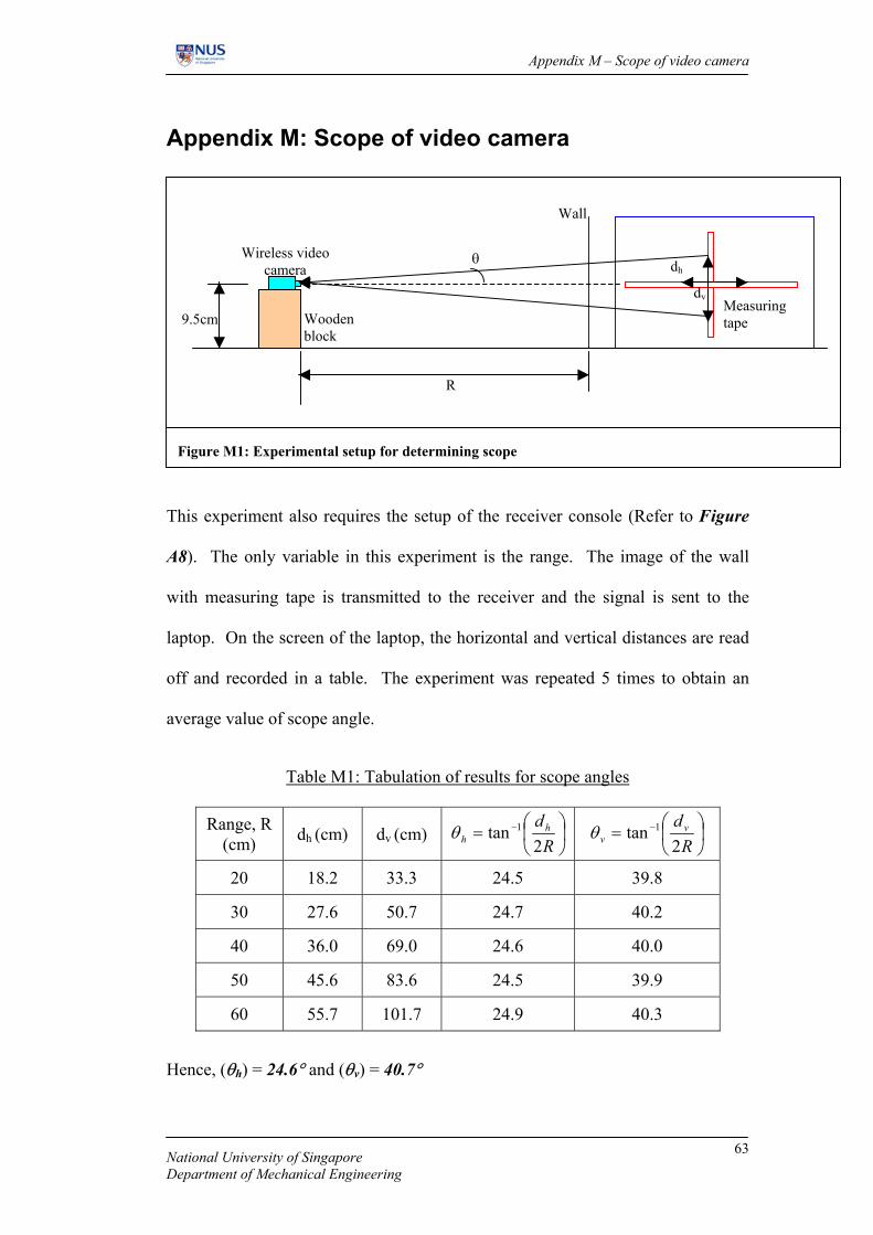
Appendix M – Scope of video camera
Appendix M: Scope of video camera
dh
dv
θ
Figure M1: Experimental setup for determining scope
Measuring tape
Wall
Wireless video camera
Wooden block
R
9.5cm
This experiment also requires the setup of the receiver console (Refer to Figure
A8). The only variable in this experiment is the range. The image of the wall
with measuring tape is transmitted to the receiver and the signal is sent to the
laptop. On the screen of the laptop, the horizontal and vertical distances are read
off and recorded in a table. The experiment was repeated 5 times to obtain an
average value of scope angle.
Table M1: Tabulation of results for scope angles
Range, R (cm) dh (cm) dv (cm)
= −
Rdh
h 2tan 1θ
= −
Rdv
v 2tan 1θ
20 18.2 33.3 24.5 39.8
30 27.6 50.7 24.7 40.2
40 36.0 69.0 24.6 40.0
50 45.6 83.6 24.5 39.9
60 55.7 101.7 24.9 40.3
Hence, (θh) = 24.6° and (θv) = 40.7°
National University of Singapore Department of Mechanical Engineering
63