milling report (indexing)
23
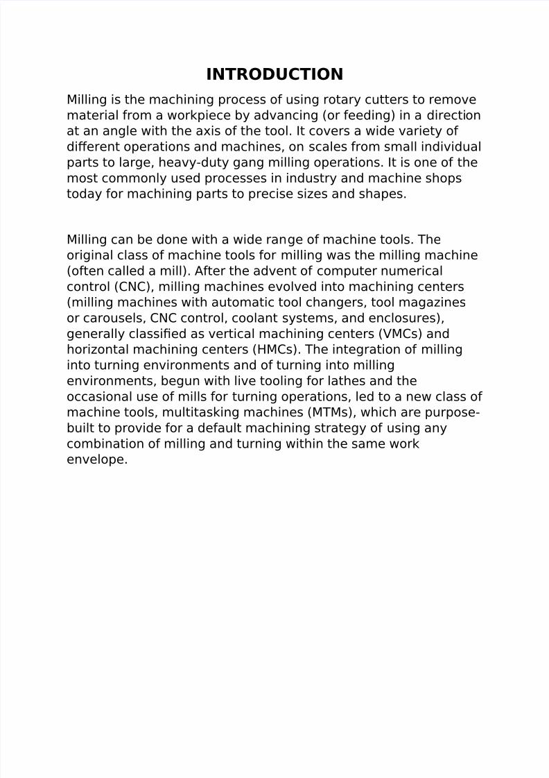
INTRODUCTION Milling is the machining process of using rotary cutters to remove material from a workpiece by advancing (or feeding) in a direction at an angle with the axis of the tool. It covers a wide variety of dierent operations and machines, on scales from small individual parts to large, heavyduty gang milling operations. It is one of the most commonly used processes in industry and machine shops today for machining parts to precise si!es and shapes. Milling can be done with a wide ran ge of machine tools. "he original class of machine tools for milling was the milling machine (often called a mill). #fter the advent of computer numerical control ($%$), milling machines evolved into machining centers (milling machines with automatic tool changers, tool maga!ines or carousels, $%$ control, coolant systems, and enclosures), generally classi&ed as vertical machining centers ('M$s) and hori!ontal machining centers (M$s). "he integration of milling into turning environments and of turning into milling environments, begun with live tooling for lathes and the occasional use of mills for turning operations, led to a new class of machine tools, multitasking machines (M"Ms), which are purpose built to provide for a default machining strategy of using any combination of milling and turning within the same work envelope.
-
Upload
aiman-alif -
Category
Documents
-
view
231 -
download
1
Transcript of milling report (indexing)
8/16/2019 milling report (indexing)
http://slidepdf.com/reader/full/milling-report-indexing 1/23
INTRODUCTION
Milling is the machining process of using rotary cutters to remove
material from a workpiece by advancing (or feeding) in a direction
at an angle with the axis of the tool. It covers a wide variety ofdierent operations and machines, on scales from small individual
parts to large, heavyduty gang milling operations. It is one of the
most commonly used processes in industry and machine shops
today for machining parts to precise si!es and shapes.
Milling can be done with a wide range of machine tools. "he
original class of machine tools for milling was the milling machine
(often called a mill). #fter the advent of computer numericalcontrol ($%$), milling machines evolved into machining centers
(milling machines with automatic tool changers, tool maga!ines
or carousels, $%$ control, coolant systems, and enclosures),
generally classi&ed as vertical machining centers ('M$s) and
hori!ontal machining centers (M$s). "he integration of milling
into turning environments and of turning into milling
environments, begun with live tooling for lathes and the
occasional use of mills for turning operations, led to a new class of
machine tools, multitasking machines (M"Ms), which are purposebuilt to provide for a default machining strategy of using any
combination of milling and turning within the same work
envelope.
8/16/2019 milling report (indexing)
http://slidepdf.com/reader/full/milling-report-indexing 2/23
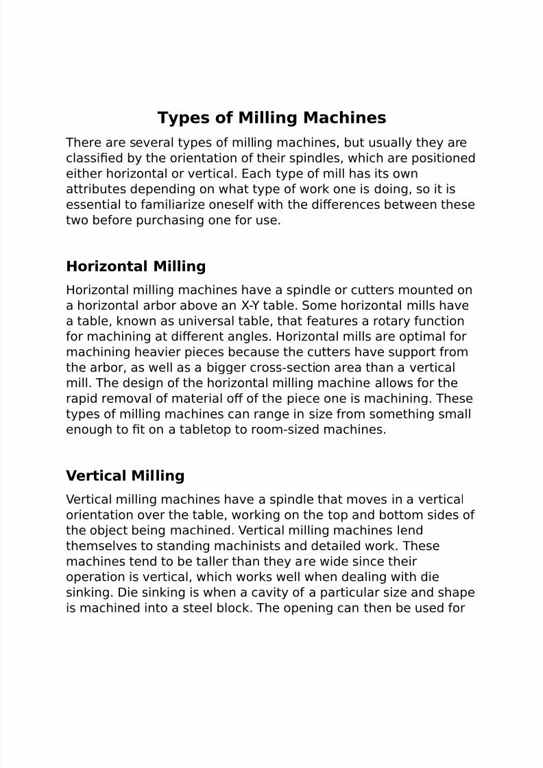
Types of Milling Machines
"here are several types of milling machines, but usually they are
classi&ed by the orientation of their spindles, which are positioned
either hori!ontal or vertical. ach type of mill has its own
attributes depending on what type of work one is doing, so it is
essential to familiari!e oneself with the dierences between these
two before purchasing one for use.
Horizontal Millingori!ontal milling machines have a spindle or cutters mounted on
a hori!ontal arbor above an *+ table. ome hori!ontal mills have
a table, known as universal table, that features a rotary function
for machining at dierent angles. ori!ontal mills are optimal for
machining heavier pieces because the cutters have support from
the arbor, as well as a bigger crosssection area than a vertical
mill. "he design of the hori!ontal milling machine allows for the
rapid removal of material o of the piece one is machining. "hesetypes of milling machines can range in si!e from something small
enough to &t on a tabletop to roomsi!ed machines.
Vertical Milling
'ertical milling machines have a spindle that moves in a vertical
orientation over the table, working on the top and bottom sides of
the ob-ect being machined. 'ertical milling machines lend
themselves to standing machinists and detailed work. "hese
machines tend to be taller than they are wide since their
operation is vertical, which works well when dealing with die
sinking. ie sinking is when a cavity of a particular si!e and shape
is machined into a steel block. "he opening can then be used for

8/16/2019 milling report (indexing)
http://slidepdf.com/reader/full/milling-report-indexing 3/23
molding plastic or for forging, coining, or diecasting. /elow are
the two types of vertical milling machines most commonly used.
Turret
"urret milling machines are classi&ed as vertical milling machines
because the spindle is positioned vertically0 it is considered a
versatile machine since it can create a wide selection of shapes.
1ike a drill press, this milling machine features a 2uill that when
lowered or raised can create dierent cutting depths0 the 2uillworks in con-unction with a part under the table called a 3knee3 to
machine a piece. "he table on this machine moves both parallel
and perpendicular to allow the machinist to make easier cuts, but
this maneuverability can add stress on the table. "urret milling
machines also tend to be smaller since it is di4cult to move a
2uill on a larger machine.
Bed Mill
5ith bed milling machines, the table moves against the axis of
the spindle. "his machine does not create as much 6exibility in
shape cutting like a turret milling machine, but this type of
con&guration is often used on larger machines.
Milling Machine u!ricants
ince machining solid materials, especially metal, can create a lot
of friction, it is extremely important for milling machines to be
properly lubricated. 1ubricants help reduce friction and cool the
machine while it performs its intended functions, which prevents
failure and damage to the mill and the piece it is machining. ach
8/16/2019 milling report (indexing)
http://slidepdf.com/reader/full/milling-report-indexing 4/23
milling machine comes with a builtin lubrication system, but it is
up to the user to maintain the lubricant for it to function correctly.
Most mill manufacturers indicate what kind of lubricant to use, but
if one is unsure, it is a good idea to try and &nd a manual online
or ask a professional to make sure what the proper lubricant isneeded for the particular machine being used.
History of Milling Machines "he milling machine performs a variety of operations, so it has
numerous historical predecessors, from the drill to the lathe. "he
&rst milling machines were developed to shape wood in the 78th
century, and as technology and the knowledge of metallurgy
advanced, these wood mills were modi&ed to cut and shape
metal. "hese machines helped fuel the pace of the Industrial
9evolution, when precise machining became increasingly
important. ince so many machinists were making ad-ustments
and developments in their own shops, it is di4cult to credit one
person with the invention of the mill. # mill of note, however, is
one built in the 7:;<s by =ames %asmyth0 his milling machine
could mill the six sides of a hex nut. >ver time, milling machines
have become synonymous with industry and manufacturing.
Modern mills employ the use of computer numerical control ($%$)
for even more ease of use and precision.

8/16/2019 milling report (indexing)
http://slidepdf.com/reader/full/milling-report-indexing 5/23
OB"#CTIV#$
7."o understand the function and feature provided by the indexing
milling machine.
?."o learn the tool and e2uipment needed while operating the
machine.
;."o understand the safety precaution when operate and handling
of indexing milling machine.
@. Introduction and working principle of milling machine,
A. ierent type of milling operations,
B. ierent type of milling machine and their main parts,
C. peci&cations of milling machines

8/16/2019 milling report (indexing)
http://slidepdf.com/reader/full/milling-report-indexing 6/23
%&'#T( RU#%
7.afety glasses worn at all times,by everyone in the shop.
?.%o long sleeves,no gloves,no open toe shoes,and no -ewelry or
watches.
;.1ong hair must be secred behind your head.
@./ecome thoroughly familiar with the machine before operating
it.
A.5hen in doubt,always ask a supervisor or shop manager.
B.%ever use the mill (or any other e2uipment) when tired or
rushed for time.
C.>nly attempt work that you have been approved to do and are
comfortable doing.
:.Det additional training,refresher courses and approval as
necessary. #E F>9 1G.
8.%ever reach anywhere over,around or near any rotating cutter.
7<.top the machine every time the cutter is not cutting,not being
used , or you are changing toolsHparts.
8/16/2019 milling report (indexing)
http://slidepdf.com/reader/full/milling-report-indexing 7/23
77.>nly remove chips using gentle air blasts or chip brushes, be
aware of cutting tools.
7?.se a chip shield to keep chips from hitting you and other in
the area.
7;.Eeep #11 rags and tools away from the machine and o
machine table during use.
7@./e sure the holding device and workpiece are both securely
clamped.
7A.#lways make sure that the cutting tool is sharp,at the correct
height and has the proper clearance.
7B.o not be distracted or talk to other when operating the
machines.
7C.o not walk way from running machines."urn them o every
time.
Conclusion
Milling machines are important for cutting and shaping wood and
metal, among other solid materials. "hese machines are aninvaluable resource for any business or individual seeking to
create precision pieces in a work or personal shop environment.
"here are several dierent types of milling machines, but the two
main types are classi&ed by the orientation of their spindleJ
hori!ontal and vertical. ince milling machines are a big
investment, it is best to research which kind best &ts oneKs budget
and needs before purchasing one particular kind of mill over
another. Milling machines can be purchased at machinery shops
or dealers. "hey can also be bought second hand and at reducedprices from warehouse li2uidation sales or previous owners,
although it is important to check the working condition of a used
mill before purchasing it. Mills can also be found online through
any authori!ed dealer or on auction sites like e/ay. Milling
machines are an integral part of the industrial world, so owning

8/16/2019 milling report (indexing)
http://slidepdf.com/reader/full/milling-report-indexing 8/23
one can be a valuable asset to oneKs business or home workshop0
it is only a matter of &nding the right mill for the right machining
-ob, and determining the right orientation is a step in the right
direction
)OR*IN+ ,RINCI,# O' MIIN+ M&CHIN#
5orking of a milling machine is based on the fact that milling
cutter is fed against workpiece. "his is achieved by developing
relative motion with precise control between workpiece and
rotating milling cutter. Feed motion is generally given to the
workpiece through its holding device. $utting mechanism of the
workpiece in milling operations is Milling cutter work piece
$onventional Gartial Face Milling nd Milling 5ork piece Milling
cutter 5ork piece Feed direction Gro&le Milling work piece Milling
cutter 5ork piece Gocket Milling cutter Gocket Milling Milling cutter
5ork piece same as that in turning operation on lathe. "his
cutting takes place due to plastic deformation of metal by the
cutting tool. Milling machine can also hold more than one cutter
at a time. "he holding device is supported by mechanism that can

8/16/2019 milling report (indexing)
http://slidepdf.com/reader/full/milling-report-indexing 9/23
oer a selective portion of the workpiece to milling cutter for its
processing. Indexing is one of the examples of this type of
processing.
,RINCI,& ,&RT% O' & MIIN+ M&CHIN#
Denerally columns and knee type milling machine is considered
as typical milling
machine. Grincipal parts of a typical milling machine are described
as below.
/ase
It provides rest for all parts of milling machine including column. It
is made of

8/16/2019 milling report (indexing)
http://slidepdf.com/reader/full/milling-report-indexing 10/23
grey iron by casting.
$olumn
It is a type of rigid vertical long box. It houses driving mechanism
of spindle, table
knee is also &xed to the guide ways of column.
Enee
Enee can be ad-usted at a height on the column. It houses the
feed mechanism of
the table and other controls.
addle
addle is placed at the top of the knee. addle provides guide
ways for the
movement of the table.
"able
"able rests on the saddle. It consists of L" shaped slots for
clamping the
workpiece. Movements of the table (feed motions) are given in
very controlled
manner be lead screw.
>verhanging #rm

8/16/2019 milling report (indexing)
http://slidepdf.com/reader/full/milling-report-indexing 11/23
>verhanging arm is mounted on the column and serves a bearing
support for the
arbor. "his arm is ad-ustable so that the bearing support may be
provided near to
the milling cutter. "here can be more than one bearing supports
to the arbor.
#rbor
It holds rotating milling cutters rigidly and mounted on the
spindle. ometimes
arbor is supported at maximum distance from support of
overhanging arm like a
cantilever, it is called stub arbor. 1ocking provisions are provided
in the arbor
assembly to ensure its reliability.
Front /race MillingFront base is used to ad-ust the relative position of knee and
overhanging arm. It is also an extra support &xed between the
knee and overhanging arm for rigidity.
pindle
pindle is pro-ected from the column face and provided with atapered hole to
accommodate the arbor. Gerformance of a milling machine
depends on the

8/16/2019 milling report (indexing)
http://slidepdf.com/reader/full/milling-report-indexing 12/23
accuracy, strength and rigidity of the spindle. pindle also
transfer the motive
power to arbor through belt or gear from column
MI11I%D M#$I%

8/16/2019 milling report (indexing)
http://slidepdf.com/reader/full/milling-report-indexing 13/23
U%IN+ TH# M&CHN#
7 Tra--ing the Head with the help of a upervisor or hopManager.
"he head of a vertical milling machine can be tilted from side to
side and from front to back. "his allows for versatility of the
machine,but these ad-ustments can drift. >ccasionally, one
should check and ad-ust the head so that the spindle will be
normal to the plane of the table."o check, install a dial indicator
into the tramming bar,and install the dial indicator on the other
end of the bar. "he indicator face should be facing up and the
probe at @A degree to the table. 1ower the spindle until the dial
indicator contacts the table then registers about one half of a
revolution. et the dial indicator is toward you and set the be!el
to !ero. 9otate the spindle by hand 7:< degrees. If the dial
indicator still reads !ero, the spindle is aligned front to back. If
not, ad-ust the head until the dial reads half of the original
reading and iterate the entire process until the error falls within
acceptable limits. 9epeat the process with the dial displaced leftand right to alight the head side to side.
?.%.uaring the Vise. $heck before every -ob, donNt assume itNs
aligned or tightened
5ork on a milling machine is most often held in a vise clamped
onto the bed. "o make sure the parts we make are s2uare and
parallel, the vice must be aligned with the * travels of the
machine. "o do this, mount the vise on the bed and secure it with
"bolts, but only lightly so as to permit ad-ustment of the
orientation of the vise. Mount a dial indicator in the spindle of the
machine with the probe facing away from you. 1ower the spindle
and run the bed of the table back until the &xed (back) -aw of the
vise is in contact with the indicator and further until the indicator

8/16/2019 milling report (indexing)
http://slidepdf.com/reader/full/milling-report-indexing 14/23
registers one half of a revolution. et the be!el to !ero. se the
manual cross feed to run the indicator across the face of the vise.
If the vise is s2uared, the indictor will remain at !ero. If the dial
indicator does not read !ero, tap lightly with a soft hammer to
realign the vise. 9epeat this procedure until the dial indicatorreads !ero through the full travel across the face of the vise -aw.
"ighten down the "bolts be careful not to change the vise
orientation.
;. %etting %pindle %peed / High0o1 +earing
pindle speed is set by turning the speed crank on the right side
of the spindle. "he spindle must be on and rotating to ad-ust thespeed. "here is a manual display (dial) on the head of the
machine that shows the speed in rpm. "he spindle speed dial has
two scales, one for low range, and one for high range. "he
machine is switched between ranges with OG 9#%DP lever
on the right side of the machine head. witching this lever must
be done with the spindle not runningQ ometimes, the spindle
must be rotated slightly (by hand) to allow the
23 Using an #dge 'inder
/efore doing precise work on a milling machine, one must locate
the edges of a part accurately. #n edge&nder is designed to do

8/16/2019 milling report (indexing)
http://slidepdf.com/reader/full/milling-report-indexing 15/23
this on edges with 6at vertical surfaces. #n edge&nder is
composed of two concentric cylinders, spring loaded together. "o
use it you must &rst insert it into the machine with the
appropriate collet. "he big end of the edge&nder is held in the
collet at least R way in. tart the spindle and set the speed toapproximately 7,<<<rpm. Flick the bottom of the edge&nder to
induce a wobble in the smaller diameter. "he smaller diameter is
usually .?<<P diameter. "hen, move the part into the tool very
slowly. "he edge &nder will center up, then break out of
concentricity suddenly. #t that point, reset the dial indicator or
digital readout for that axis of the machine to a value e2ual the
radius of the edge&nder. 9epeat the process at least twice to
make sure your edge &nding was correct.
A. Using the Digital ReadOuts commonly known as 9>s
"he mills are e2uipped with electronic display for accurate
positioning. "hese 9>s have a @ place display (.<<<?Paccuracy)
for the * and + axes. "he S axes is still read o the mechanical
dial on the Saxis handle with a .<<7P accuracy. "here are two
systems of measurement that the 9>s can supply, Incrementaland #bsolute. #bsolute should be used for the O!eroP corner of
your part and not be changed during the -ob. "he incremental
setting can be O!eroedP as necessary for use between any two
locations, features, holes, etcT.

8/16/2019 milling report (indexing)
http://slidepdf.com/reader/full/milling-report-indexing 16/23
B. $utting Fluids and their applications.
ierent applications andHor materials re2uire slightly dierent
cutting 6uids. "hese 6uids are designed to provide the correct
amount of lubricity, cooling, better surface &nish, increased tool
life and more. #ll cutting 6uids (especially 577) should be
thoroughly cleaned H removed from the machine when &nishedQ
"he machine should be dry and a light OmistingP of 5@< applied
to the entire vice, tables and machine ways to prevent corrosion.
U%IN+ ,&R&#% in a Eurt vice.
Garallels are used to raise the work above the vice -aws for
machining, drilling or other operations. "hey can set the part
height so the vice -aws will not be hit by your cutting tools and
that any drilling operations will not cut into the bottom of the
vice. Make sure you use a matching (height) set. #lso be aware of
running into the parallels, and constantly check to see that theyhave not moved unintentionally. It is a good idea to always check
that no chips have fallen on toip of or underneath the parallels, as
this will greatly eect the accuracy of your parts.
%4U&RIN+ %TOC* / '&C# MIIN+ First step in accurate parts
"o create a s2uare corner on a part, &rst orient an already &nished
edge vertically in the vise and clamp lightly onto the part. et a
machinistKs s2uare against the &nished edge and the bottom of
the vise. 1ightly tap the part with a plastic hammer to align it withthe s2uare. $lamp the vise down securely. %ow the top edge of
the part is ready to be milled to hori!ontal. It is often necessary to
create a 6at face on a large part. "his is called face milling. elect
a sharp, 6at bottom, end mill cutter a little wider than the
workpiece so that the facing can be accomplished in one pass.

8/16/2019 milling report (indexing)
http://slidepdf.com/reader/full/milling-report-indexing 17/23
"his can work for end mills up to .CA<P diameter in si!e. /eyond
that si!e, you will have to make multiple passes or use a
6ycutter.Fly cutting, which is also called single point milling, is
one of the most versatile milling operations. It is done with a
singlepoint cutting tool shaped like a lathe tool bit. It is held androtated by a 6y cutter arbor. +ou can grind this cutter to almost
any form that you need. It is more economical to grind the desired
form on a lathetype tool bit than to buy a preground form cutter,
which is very expensive and usually suitable only for one
particular -ob. For milling slots, end mills are an idea tool. "hey
will produce a slot to within two onethousandths of an inch in one
pass. If greater accuracy is re2uired, use an end mill a little
smaller than the desired slot. Measure the slot you produced and
then open it to the desired dimension with a second pass. %otethat the depth of cut should not exceed three times the diameter
of the cutter.
DRIIN+5 BORIN+ / R#&MIN+ Much more accurate than a
drill press
"he milling machine may be used eectively for drilling, since
accurate location of the hole may be secured by means of table
positioning. pacing holes in a circular path, such as the holes in
an index plate, may be accomplished by indexing with the index
head positioned vertically. "wist drills may be supported in drill
chucks fastened in the milling machine spindle or mounted
directly in milling machine collets or adapters. "he workpiece to
be drilled is fastened to the milling machine table by clamps,
vises, or angle plates. For boring, there are various types ofboring tool holders may be used for boring on the milling
machine, the boring tools being provided with either straight
shanks to be held in chucks and holders or taper shanks to &t
collets and adapters. "he two attachments most commonly used
for boring is the oset boring head, also known as the O$riterion
/oring eadP "he singleedge cutting tool used for boring on the

8/16/2019 milling report (indexing)
http://slidepdf.com/reader/full/milling-report-indexing 18/23
milling machine is the same as a lathe cutter bit. $utting speeds,
feeds, and depth of cut should be the same as that prescribed for
lathe operations. /oring is usually used for holes bigger than .
A<<P diameter. "he most accurate way to &nish a hole smaller
than .A<<P diameter is the process of reaming. 9eaming is aprocess which slightly enlarges a preexisting hole to a tightly
toleranced diameter. # reamer is similar to a mill bit in that it has
several cutting edges arranged around a central shaft. 9eaming is
always done after hole drilling. If the hole is drill crooked, the
reamer will follow the crooked hole. 9eaming should not be relied
upon to correct the location or alignment of a hole. 9eamed holes
should not intersect with drilled holes. Its primary purpose is to
&netune the diameter of the hole. 9eaming is most accurate for
axially symmetric parts produced and reamed on a mill. 9eamerscome in a multitude of si!es.
Maintenance and ser6icing of -illing
-achines
1ike any other machine, milling machines are sub-ect to wear and
tear. "he physical wear is a result of the use of the machines and
of the abrasion caused by friction during use. uch wear can be
reduced by regular maintenance and servicing of the milling
machine by the operatorJ
"he degree of wear depends onJ

8/16/2019 milling report (indexing)
http://slidepdf.com/reader/full/milling-report-indexing 19/23
maintenance and servicing of the milling machine,
properties of coolants and lubricants,
environmental conditions (dust, temperature variations, etc.)
operating conditions (single or multishift operation, volume of
metal removed, proper operation).
&d6antages
7. "he metal is removed at a faster rate as the cutter has got
multiple cutting edges and rotates at a higher speed.
?. It is possible to perform machining by mounting more than onecutter at a time.
;. "he table of the machine can be moved to an accuracy of
<.<?mm.
@. It is very useful since various cutters and precise tools can be
machined.

8/16/2019 milling report (indexing)
http://slidepdf.com/reader/full/milling-report-indexing 20/23
A. pecial attachments can be mounted on the machine to
perform operations that are performed in other machine tools.
B. "he 2uality of the shop is enhanced with the presence of this
machine.
Disad6antages
7. "he cost of the milling machine is high.
?. #s milling cutters cost high, the investment for procuring tools
is more.
;. "he production cost will increase if we carry out the operations
performed in a shaper or a drilling machine with a milling
machine.
Inde7ing heads
$rosssection of an indexing head
# dividing head mounted on the table of a small milling machine.
"he direct indexing plate and center are visible facing the camera.
#n interchangeable indexing plate is visible on the left side.
Indexing is an operation of dividing a periphery of a cylindrical
workpiece into e2ual number of divisions by the help of index

8/16/2019 milling report (indexing)
http://slidepdf.com/reader/full/milling-report-indexing 21/23
crank and index plate. # manual indexing head includes a hand
crank. 9otating the hand crank in turn rotates the spindle and
therefore the workpiece. "he hand crank uses a worm gear drive
to provide precise control of the rotation of the work. "he work
may be rotated and then locked into place before the cutter isapplied, or it may be rotated during cutting depending on the
type of machining being done.
Most dividing heads operate at a @<J7 ratio0 that is @< turns of the
hand crank generates 7 revolution of the spindle or workpiece. In
other words, 7 turn of the hand crank rotates the spindle by 8
degrees. /ecause the operator of the machine may want to rotate
the part to an arbitrary angle indexing plates are used to ensure
the part is accurately positioned.irect indexing plateJ Most dividing heads have an indexing plate
permanently attached to the spindle. "his plate is located at the
end of the spindle, very close to where the work would be
mounted. It is &xed to the spindle and rotates with it. "his plate is
usually e2uipped with a series of holes that enables rapid
indexing to common angles, such as ;<, @A, or 8< degrees. # pin
in the base of the dividing head can be extended into the direct
indexing plate to lock the head 2uickly into one of these
angles."he advantage of the direct indexing plate is that it is fast
and simple and no calculations are re2uired to use it. "he
disadvantage is that it can only be used for a limited number of
angles.
Interchangeable indexing plates are used when the work must be
rotated to an angle not available on the direct indexing plate.
/ecause the hand crank is &xed to the spindle at a known ratio
(commonly @<J7) the dividing plates mounted at the handwheel
can be used to create &ner divisions for precise orientation atarbitrary angles. "hese dividing plates are provided in sets of
several plates. ach plate has rings of holes with dierent
divisions. For example, an indexing plate might have three rows of
holes with ?@, ;<, and ;B holes in each row. # pin on the hand
crank engages these holes. Index plates with up to @<< holes are

8/16/2019 milling report (indexing)
http://slidepdf.com/reader/full/milling-report-indexing 22/23
available. >nly one such plate can be mounted to the dividing
head at a time. "he plate is selected by the machinist based on
exactly what angle he wishes to index to.
For example, if a machinist wanted to index (rotate) his workpiece
by ??.A degrees then he would turn the hand crank two full
revolutions plus onehalf of a turn. ince each full revolution is 8
degrees and a halfrevolution is @.A degrees, the total is ??.A (8 U
8 U @.A V ??.A). "he onehalf turn can easily be done precisely
using any indexing plate with an even number of holes and
rotating to the halfway point (ole W: on the 7Bhole ring).
/rown and harpe indexing heads include a set of ; indexing
plates. "he plates are marked W7, W? and W;, or 3#3, 3/3 and 3$3.
ach plate contains B rows of holes. Glate W7 or 3#3 has 7A, 7B,7C, 7:, 78, and ?< holes. Glate W? or 3/3 has ?7, ?;, ?C, ?8, ;7,
and ;; holes. Glate W; or 3$3 has ;C, ;8, @7, @;, @C, and @8 holes.
Xcitation neededY
niversal ividing headsJ some manual indexing heads are
e2uipped with a power drive provision. "his allows the rotation of
the dividing head to be connected to the table feed of the milling
machine instead of using a hand crank. # set of change gears is
provided to select the ratio between the table feed and rotation. "his setup allows the machining of spiral or helical features such
as spiral gears, worms, or screw type parts because the part is
simultaneously rotated at the same time it is moved in the
hori!ontal direction. "his setup is called a 3G"> dividing head3.

8/16/2019 milling report (indexing)
http://slidepdf.com/reader/full/milling-report-indexing 23/23
R#'#R#NC#%
httpsJHHen.wikipedia.orgHwikiHIndexingZhead
httpJHHcollections.infocollections.orgHukeduHenHdH=gt!7<@aeH;.html
httpJHHwww.lathes.co.ukHindexH