Millimeter Wave Cellular Networks: A MAC Layer Perspective
22
IEEE TRANSACTIONS ON COMMUNICATIONS, VOL. 63, NO. 10, OCTOBER 2015 3437 Millimeter Wave Cellular Networks: A MAC Layer Perspective Hossein Shokri-Ghadikolaei, Student Member, IEEE, Carlo Fischione, Member, IEEE, Gábor Fodor, Senior Member, IEEE, Petar Popovski, Senior Member, IEEE, and Michele Zorzi, Fellow, IEEE (Invited Paper) Abstract—The millimeter-wave (mmWave) frequency band is seen as a key enabler of multigigabit wireless access in future cel- lular networks. In order to overcome the propagation challenges, mmWave systems use a large number of antenna elements both at the base station and at the user equipment, which leads to high directivity gains, fully directional communications, and possible noise-limited operations. The fundamental differences between mmWave networks and traditional ones challenge the classical design constraints, objectives, and available degrees of freedom. This paper addresses the implications that highly directional communication has on the design of an efficient medium access control (MAC) layer. The paper discusses key MAC layer issues, such as synchronization, random access, handover, channelization, interference management, scheduling, and association. This paper provides an integrated view on MAC layer issues for cellular networks, identifies new challenges and tradeoffs, and provides novel insights and solution approaches. Index Terms—Millimeter wave communication, 5G, MAC layer design, control channel, random access, synchronization, resource allocation. I. I NTRODUCTION T HE increased rate demand in the upcoming 5G wire- less systems and the fact that the spectral efficiency of microwave links is approaching its fundamental limits have Manuscript received February 21, 2015; revised June 26, 2015; accepted July 7, 2015. Date of publication July 14, 2015; date of current version October 15, 2015. The work of H. Shokri-Ghadikolaei and C. Fischione was supported by the Swedish Research Council under the project “In-Network Optimization.” The work of G. Fodor was supported in part by the Swedish Foundation for Strategic Research through the Strategic Mobility Matthew Project under Grant SM13-0008. The work of P. Popovski has partially been performed in the framework of the FP7 project ICT-317669 METIS, which is supported in part by the European Union. The work of M. Zorzi was supported in part by New York University. The associate editor coordinating the review of this paper and approving it for publication was Z. Dawy. H. Shokri-Ghadikolaei and C. Fischione are with KTH Royal Institute of Technology, 114 28 Stockholm, Sweden (e-mail: [email protected]; carlofi@ kth.se). G. Fodor is with the School of Electrical Engineering, KTH Royal Institute of Technology, 114 28 Stockholm, Sweden, and also with Ericsson Research, 164 83 Kista, Sweden (e-mail: [email protected]). P. Popovski is with the Department of Electronic Systems, Aalborg Univer- sity, 9100 Aalborg, Denmark (e-mail: [email protected]). M. Zorzi is with the Department of Information Engineering, University of Padova, 35131 Padova, Italy (e-mail: [email protected]). Color versions of one or more of the figures in this paper are available online at http://ieeexplore.ieee.org. Digital Object Identifier 10.1109/TCOMM.2015.2456093 motivated consideration of higher frequency bands that offer abundance of communication bandwidth. There is a growing consensus in both industry and academia that millimeter wave (mmWave) will play an important role in 5G wireless systems [1]–[6] in providing very high data rates. The commercial potential of mmWave networks initiated several standardization activities within wireless personal area networks (WPANs) and wireless local area networks (WLANs), such as IEEE 802.15.3 Task Group 3c (TG3c) [7], IEEE 802.11ad standardization task group [8], WirelessHD consortium, and wireless gigabit alliance (WiGig). Although there has been no dedicated stan- dardization activity for mmWave in cellular networks so far, there are several ongoing discussions within research projects such as FP7 EU Project METIS [6] (2012–2015) on how to incorporate mmWave networks in 5G. The high attenuation mitigates interference, while directionality supports wireless backhauling among micro and macro base stations (BSs) [9]; hence mmWave communication is suitable for dense heteroge- neous deployments. The special propagation features [10] and hardware requirements [11] of mmWave systems bring multiple challenges at the physical, medium access control (MAC), and routing layers. These challenges are exacerbated due to the expected spectrum heterogeneity in 5G, i.e., integration of and coexistence with the microwave communication standards. As pointed out in the editorials of two recent special issues dedicated to the use of mmWave in 5G [12], [13], the communi- cation architecture and protocols, especially at the MAC layer, need to be revised to adapt signaling and resource allocation and cope with severe channel attenuation, directionality, and blockage. In this paper, we identify the main challenges of mmWave cellular communications at the MAC layer. We show novel design approaches for three aspects: 1) Control Channel Architecture: We highlight the necessity for a directional control plane in mmWave bands, identify the available options for that purpose, and discuss why an omnidirectional physical control channel in microwave bands can significantly boost the performance of the control plane. 2) Initial Access, Mobility Management, and Handover: Leveraging the advantages of both omnidirectional microwave and directional mmWave control channel, we suggest a two- step synchronization procedure. We compare contention-free to contention-based random access protocols, and show that 0090-6778 © 2015 IEEE. Personal use is permitted, but republication/redistribution requires IEEE permission. See http://www.ieee.org/publications_standards/publications/rights/index.html for more information.
Transcript of Millimeter Wave Cellular Networks: A MAC Layer Perspective
IEEE TRANSACTIONS ON COMMUNICATIONS, VOL. 63, NO. 10, OCTOBER 2015 3437
Millimeter Wave Cellular Networks:A MAC Layer Perspective
Hossein Shokri-Ghadikolaei, Student Member, IEEE, Carlo Fischione, Member, IEEE,Gábor Fodor, Senior Member, IEEE, Petar Popovski, Senior Member, IEEE, and Michele Zorzi, Fellow, IEEE
(Invited Paper)
Abstract—The millimeter-wave (mmWave) frequency band isseen as a key enabler of multigigabit wireless access in future cel-lular networks. In order to overcome the propagation challenges,mmWave systems use a large number of antenna elements both atthe base station and at the user equipment, which leads to highdirectivity gains, fully directional communications, and possiblenoise-limited operations. The fundamental differences betweenmmWave networks and traditional ones challenge the classicaldesign constraints, objectives, and available degrees of freedom.This paper addresses the implications that highly directionalcommunication has on the design of an efficient medium accesscontrol (MAC) layer. The paper discusses key MAC layer issues,such as synchronization, random access, handover, channelization,interference management, scheduling, and association. This paperprovides an integrated view on MAC layer issues for cellularnetworks, identifies new challenges and tradeoffs, and providesnovel insights and solution approaches.
Index Terms—Millimeter wave communication, 5G, MAC layerdesign, control channel, random access, synchronization, resourceallocation.
I. INTRODUCTION
THE increased rate demand in the upcoming 5G wire-less systems and the fact that the spectral efficiency of
microwave links is approaching its fundamental limits have
Manuscript received February 21, 2015; revised June 26, 2015; acceptedJuly 7, 2015. Date of publication July 14, 2015; date of current versionOctober 15, 2015. The work of H. Shokri-Ghadikolaei and C. Fischione wassupported by the Swedish Research Council under the project “In-NetworkOptimization.” The work of G. Fodor was supported in part by the SwedishFoundation for Strategic Research through the Strategic Mobility MatthewProject under Grant SM13-0008. The work of P. Popovski has partially beenperformed in the framework of the FP7 project ICT-317669 METIS, which issupported in part by the European Union. The work of M. Zorzi was supportedin part by New York University. The associate editor coordinating the review ofthis paper and approving it for publication was Z. Dawy.
H. Shokri-Ghadikolaei and C. Fischione are with KTH Royal Institute ofTechnology, 114 28 Stockholm, Sweden (e-mail: [email protected]; [email protected]).
G. Fodor is with the School of Electrical Engineering, KTH Royal Instituteof Technology, 114 28 Stockholm, Sweden, and also with Ericsson Research,164 83 Kista, Sweden (e-mail: [email protected]).
P. Popovski is with the Department of Electronic Systems, Aalborg Univer-sity, 9100 Aalborg, Denmark (e-mail: [email protected]).
M. Zorzi is with the Department of Information Engineering, University ofPadova, 35131 Padova, Italy (e-mail: [email protected]).
Color versions of one or more of the figures in this paper are available onlineat http://ieeexplore.ieee.org.
Digital Object Identifier 10.1109/TCOMM.2015.2456093
motivated consideration of higher frequency bands that offerabundance of communication bandwidth. There is a growingconsensus in both industry and academia that millimeter wave(mmWave) will play an important role in 5G wireless systems[1]–[6] in providing very high data rates. The commercialpotential of mmWave networks initiated several standardizationactivities within wireless personal area networks (WPANs) andwireless local area networks (WLANs), such as IEEE 802.15.3Task Group 3c (TG3c) [7], IEEE 802.11ad standardizationtask group [8], WirelessHD consortium, and wireless gigabitalliance (WiGig). Although there has been no dedicated stan-dardization activity for mmWave in cellular networks so far,there are several ongoing discussions within research projectssuch as FP7 EU Project METIS [6] (2012–2015) on how toincorporate mmWave networks in 5G. The high attenuationmitigates interference, while directionality supports wirelessbackhauling among micro and macro base stations (BSs) [9];hence mmWave communication is suitable for dense heteroge-neous deployments. The special propagation features [10] andhardware requirements [11] of mmWave systems bring multiplechallenges at the physical, medium access control (MAC),and routing layers. These challenges are exacerbated due tothe expected spectrum heterogeneity in 5G, i.e., integration ofand coexistence with the microwave communication standards.As pointed out in the editorials of two recent special issuesdedicated to the use of mmWave in 5G [12], [13], the communi-cation architecture and protocols, especially at the MAC layer,need to be revised to adapt signaling and resource allocationand cope with severe channel attenuation, directionality, andblockage.
In this paper, we identify the main challenges of mmWavecellular communications at the MAC layer. We show noveldesign approaches for three aspects:
1) Control Channel Architecture: We highlight the necessityfor a directional control plane in mmWave bands, identifythe available options for that purpose, and discuss why anomnidirectional physical control channel in microwave bandscan significantly boost the performance of the control plane.
2) Initial Access, Mobility Management, and Handover:Leveraging the advantages of both omnidirectional microwaveand directional mmWave control channel, we suggest a two-step synchronization procedure. We compare contention-freeto contention-based random access protocols, and show that
0090-6778 © 2015 IEEE. Personal use is permitted, but republication/redistribution requires IEEE permission.See http://www.ieee.org/publications_standards/publications/rights/index.html for more information.

3438 IEEE TRANSACTIONS ON COMMUNICATIONS, VOL. 63, NO. 10, OCTOBER 2015
the latter becomes more justifiable to be incorporated in theinitial access phase, as the transmission/reception beamwidthsbecome narrower. However, the increased directionality maylead to a prolonged backoff time during random access, whichwe address by proposing a novel MAC layer signal. We alsodiscuss how to manage the mobility and alleviate frequenthandover problems in mmWave cellular networks.
3) Resource Allocation and Interference Management: Thedirectional pencil-beam operation provides many options toform different cells and allocate resources, while significantlysimplifying interference management. We identify new trade-offs among throughput enhancement, fair scheduling, and highconnection robustness, and formulate a suitable optimizationproblem based on long-term resource allocation. Finally, weshow that additional RF chains at the BS can bring gains interms of network throughput, fairness, and minimum UE rate,and discuss the limits on these gains when we use directionalityat the BSs and/or the UEs.
The detailed discussions of this paper aim to demystifyMAC layer design of mmWave cellular networks and showthat there are many degrees of freedom that can be leveragedto significantly improve the performance, e.g., in terms of areaspectral efficiency, energy efficiency, robustness, uniform QoSprovisioning.
The rest of this paper is organized as follows. In Section II,we describe the essential aspects of mmWave cellular networks.In Section III, different options to realize a physical controlchannel will be discussed in detail. Section IV discusses de-sign aspects of synchronization, random access, and handoverprocedures in mmWave cellular networks. Resource allocationproblems are discussed in Section V. Concluding remarks andfuture research directions are provided in Section VI. To pre-serve the natural flow of the discussions, we present technicaldetails, which are an integral part of the contributions of thepaper, in the Appendices.
II. FUNDAMENTALS
A. The Directed mmWave Wireless Channel
MmWave communications use frequencies in the range30–300 GHz, albeit the frequencies 10–30 GHz are also oftenreferred to as mmWave [10], [14], [15]. The main character-istics of mmWave are short wavelength/high frequency, largebandwidth, high interaction with atmospheric constituents suchas oxygen, and high attenuation through most solid materials.This leads to a sparse-scattering environment, where the ma-jority of the channel directions of arrivals (DoAs) are belowthe noise floor [10], [15]–[17]. The sparsity in the angulardomain (or equivalently the sparsity in the dominant channeleigenmodes) can be leveraged to realize efficient channel es-timation and beamforming algorithms [18]–[21]. Very smallwavelengths allow implementation of a large number of an-tenna elements in the current size of radio chips, which booststhe achievable directivity gain, though at the price of extrasignal processing. Such a gain can largely or even completelycompensate the high path-loss (i.e., the distance-dependentcomponent of the attenuation) without the need to increase thetransmission power.
A channel in a mmWave system can be established in a spe-cific direction (governed by nonzero channel eigenmodes) witha range that varies according to the directionality level. Thisresults in two consequences: (1) blockage and (2) deafness.Blockage refers to high penetration loss due to obstacles andcannot be solved by just increasing the transmission power. Thehuman body can attenuate mmWave signals by 35 dB [22], [23],and materials such as brick and glass attenuate them by as muchas 80 dB and 50 dB [15], [24]–[26]. Overcoming blockagerequires a search for alternative directed spatial channels thatare not blocked, and this search entails a new beamformingoverhead. This complicates mmWave MAC design for cellularnetworks compared to WPANs/WLANs, wherein short rangestill allows non-line-of-sight (NLoS) communications [7], [8].Furthermore, the traditional notion of cell boundary becomesblurry in mmWave networks due to randomly located obstacles.This and other reasons, discussed later, demand reconsidera-tion of the traditional cell definition. Early examples includethe concepts of soft cell [27], [28] and phantom cell [29].In mmWave cellular networks, instead, we can extend thoseconcepts to that of dynamic cell, which is dynamically redefinedto meet QoS demands of the UEs, overcome blockage, andoptimize network utility, see Section V. Deafness refers tothe situation in which the main beams of the transmitter andthe receiver do not point to each other, preventing establish-ment of a communication link. On the negative side, deaf-ness complicates the link establishment phase. On the positiveside, it substantially reduces interference [30], as the receiveronly listens to a specific directed spatial channel. This makesthe conventional wisdom of interference-limited microwavewireless networks not applicable to a noise-limited mmWavesystem,1 heavily affecting both the initial access procedure andresource allocation, as will be discussed in Sections IV and V.
B. Heterogeneity
To overcome the physical limitations of mmWave, the MACmechanisms may have to exploit both microwave and mmWavebands simultaneously [15] and also facilitate co-existence ofseveral communication layers with different coverage. Conse-quently, there will be two types of heterogeneity in mmWavecellular networks:
Spectrum Heterogeneity: MmWave UEs may use both high(above 6 GHz) and low frequencies (microwave, such as theLTE band). While higher frequencies provide a massive amountof bandwidth for data communications, enabling very highdata rates, the lower frequencies may be exploited for controlmessage exchange, which demands much lower data rates buthigher reliability than data communications. This facilitates thedeployment of mmWave networks due to possible omnidirec-tional transmission/reception of control messages, as well ashigher link stability, at lower frequencies.
1Rigorously speaking, having negligible multiuser interference does not nec-essarily imply that the performance of the network is limited by noise; rather,it can be limited by the channel establishment and maintenance overhead [31].However, the negligible (or, more generally, significantly reduced) multiuserinterference is enough to establish our results especially in resource allocationand interference management in Section V.

SHOKRI-GHADIKOLAEI et al.: mmWave CELLULAR NETWORKS 3439
Fig. 1. Directional communications and beamforming: (a) a typical cellular network and (b) two-stage hybrid digital–analog beamforming architecture. Cellboundaries are intentionally omitted from (a) to indicate their loose meaning in mmWave cellular networks. The effective channel is illustrated in (b).
Deployment Heterogeneity: There will be macrocells, mi-crocells, femtocells, and even picocells, all working togetherin 5G. This heterogeneity introduces two deployment sce-narios for mmWave cellular networks: stand-alone and inte-grated networks [28]. In the stand-alone scenario, a completemmWave network (from macro to pico levels) will be deployedin the mmWave band, whereas the integrated solution is anamendment to existing microwave networks for performanceenhancement, and may be considered as an intermediate stepin the migration from existing microwave networks to futuremmWave networks. The integrated network includes mmWavesmall cells and/or mmWave hotspots [14].
Spectrum and deployment heterogeneity affect the optionsfor realizing physical control channels, see Section III.
C. Beamforming
Beamforming is the key technique to compensate the severechannel attenuation and to reduce interference in mmWavenetworks. Fig. 1(a) shows a typical cellular network whereeach entity may support multi-beam directional operation. Thisallows BSs to benefit from multiplexing to increase data rate
or use spatial diversity to achieve robustness to blockage.Generally, a wireless link can be established in omnidirectional(both BS and UE are omnidirectional), semi-directional (eitherBS or UE is omnidirectional, the other directional), or fully-directional (both BS and UE are directional) communicationmodes. Fig. 1(a) shows that inter-cell interference in both down-link and uplink is significantly reduced by fully directionalpencil-beam communication, emphasizing the noise-limitedtrend of a mmWave cellular network. Generally speaking, thereare three beamforming architectures, namely digital, analog,and hybrid.
1) Digital Beamforming: This architecture provides thehighest flexibility in shaping the transmitted beam(s), howeverit requires one baseband-to-RF chain (in short RF chain) perantenna element. This increases the cost and complexity due tothe large number of antenna elements operating in very widebandwidth. Considering one high resolution analog–digitalconverter (ADC) per RF chain, digital beamforming also leadsto high power consumption both at the BS and at the UEs,which is at odds with the design goals of 5G [5], [6], [32], [33].Moreover, digital beamforming requires estimation of the chan-nel between every pair of antenna elements of the transmitter

3440 IEEE TRANSACTIONS ON COMMUNICATIONS, VOL. 63, NO. 10, OCTOBER 2015
and the receiver. Apart from a more complicated precoding, thecomplexity of this estimation scales at least linearly with thenumber of transmitter antenna elements2 [36]. In time divisionduplexing (TDD) systems, channel state information (CSI) atthe transmitter can be obtained using uplink sounding signals.The advantage is that the overhead will be scaled with thecombined number of UEs’ antennas that can be much less thanthe number of BS antennas. However, the limited UE power andthe possible lack of beamforming gains for the uplink referencesignals may limit the performance of the network. Also, CSIacquisition by uplink reference signals requires the principleof channel reciprocity that holds if the duplexing time is muchshorter than the coherence time of the channel. The coherencetime in mmWave bands is around an order of magnitude lowerthan that of microwave bands, as the Doppler shift scales lin-early with frequency. Therefore, TDD at mmWave bands needsto be restricted to low-mobility scenarios. In frequency divisionduplexing (FDD) systems, CSI estimation should be done inboth uplink and downlink directions due to the lack of reci-procity. While CSI estimation overhead in the uplink is similarto the TDD case, the overhead in the downlink channel scaleswith the number of BS antennas, which becomes infeasible asthe number of BS antennas grows large [36]–[38]. Altogether,for systems operating in very wide spectrum ranges, such asseveral hundreds of MHz, and employing a large number ofantennas, a complete digital beamforming solution using thecurrent requirements (one high resolution ADC per RF chainand channel estimation per antenna element), is hardly feasibleand economical [37], [39]. Low-resolution ADCs (ideally withonly one bit) and sparse channel estimation are promising so-lutions for enabling digital beamforming in mmWave systems(see [38], [40] and references therein).
2) Analog Beamforming: This technique shapes the outputbeam with only one RF chain using phase shifters [37], [41].On the positive side, a simple beam-searching procedure canbe used here to efficiently find the optimal beams at thetransmitter and the receiver, as already established in existingmmWave WPAN and WLAN standards [7], [8]. With finite sizecodebooks each covering a certain direction, those standardsrecommend an exhaustive search over all possible combinationsof the transmission and reception directions through a sequenceof pilot transmissions. The combination of vectors that maxi-mizes the signal-to-noise ratio is selected for the beamforming.This procedure alleviates the need for instantaneous CSI, atthe expense of a new alignment-throughput tradeoff [42]. Thetradeoff shows that excessively increasing the codebook size (orequivalently using extremely narrow beams) is not beneficial ingeneral due to the increased alignment overhead, and there isan optimal codebook size (optimal beamwidth) at which thetradeoff is optimized. On the negative side, one RF chain canform only one beam at a time without being able to multi-plex within the beam, implying that this architecture providesonly directivity gain. For narrow beam operation, pure analogbeamforming requires several RF chains to serve UEs thatare separated geographically. This diminishes the advantages
2The complexity will be increased if the beamforming algorithm requireschannel state information both at the transmitter and at the receiver [34], [35].
of this architecture such as low complexity and low powerconsumption.
3) Hybrid Beamforming: A promising architecture formmWave cellular networks is a two-stage hybrid digital–analogbeamforming procedure, allowing the use of a very large num-ber of antennas with a limited number of RF chains [39], [43],[44]. With the hybrid solution, digital precoding is applied forthe effective channel consisting of the analog beamformingweights and the actual channel matrix, see Fig. 1(b). Analogbeamforming provides spatial division and directivity gains,which can be used to compensate the severe channel attenua-tion, by directing the transmitted signal toward different sectors.Furthermore, digital beamforming may be used to reduce intra-sector interference and provide multiplexing gain using CSI ofan effective channel with much smaller dimension. Exploitingthe sparse-scattering nature of mmWave channels, the complex-ity of hybrid beamforming design can be further reduced [19],[20], [38]. The analysis of [19] shows that, in a single userMIMO system, hybrid beamforming can almost achieve thethroughput performance of a fully digital beamforming with8 to 16 times fewer RF chains, leading to greatly reducedenergy consumption and processing overhead with a negligibleperformance drop. However, analysis and optimization of thetradeoff between the number of employed RF chains and theachievable network throughput in multiuser MIMO system andin the presence of CSI errors in wideband mmWave systemsrequires further research, see [18], [45] and the referencestherein. In Sections IV and V, we will discuss this tradeoff andshow how the hybrid beamforming architecture interplays withhandover and scheduling decisions.
III. REALIZATION OF PHYSICAL CONTROL CHANNELS
A. Essential Tradeoffs
Reliable control channels are essential for synchronization,cell search, user association, channel estimation, coherent de-modulation, beamforming procedures, and scheduling grant no-tifications, as well as multi-antenna transmission and receptionconfiguration. While control channels are defined as logicalchannels, they have to be mapped to some physical channelsto be transmitted over the radio interface, thus the specialcharacteristics of mmWave bands affect the control channelperformance from several aspects. In particular, two types oftradeoffs arise when realizing a physical control channel (PHY-CC), namely fall-back and directionality tradeoffs, which donot exist in traditional cellular networks on microwave bands,see Fig. 2.
The fall-back tradeoff is the tradeoff between sending con-trol messages over microwave or mmWave frequencies. Whilerealizing a PHY-CC in mmWave bands enables the use of asingle transceiver, the established channel is subject to highattenuation and blockage. On the other hand, a microwave PHY-CC facilitates broadcasting and network synchronization dueto larger coverage and higher link stability compared to itsmmWave counterpart, as will be discussed in Section IV-A,at the expense of higher hardware complexity and energyconsumption, since a dedicated transceiver should be tuned onthe microwave PHY-CC.
SHOKRI-GHADIKOLAEI et al.: mmWave CELLULAR NETWORKS 3441
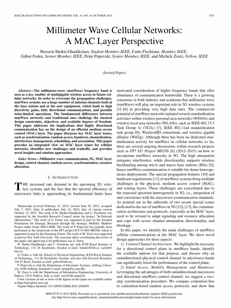
Fig. 2. Fall-back and directionality tradeoffs in realizing a PHY-CC. Mi-crowave bands provide a reliable channel with much larger coverage comparedto mmWave channels (a). Directional control channel increases coverage andmay provide more efficient PHY-CC (in terms of energy and spectral efficiency)at the expense of extra spatial search (b). Different options of realizing a PHY-CC are various combinations of these tradeoffs.
The directionality tradeoff, from another perspective, refersto the option of establishing a PHY-CC in omnidirectional,semi-directional, or fully-directional communication modes.Although an omnidirectional PHY-CC has a shorter commu-nication range, all devices within that range can receive thecontrol messages without any deafness problem. The semi-directional option increases the transmission range, while in-troducing less interference to the network. However, mitigatingthe deafness problem in this case may require a spatial searchthat introduces extra delay. Finally, the fully-directional com-munication mode further increases coverage and decreases theinterference caused to the network at the expense of even higherspatial search overhead.3
To have a better sense of the interplay between directional-ity and transmission range, we consider the simple distance-dependent path-loss model of [15, Equation (1)]. Fixingtransmission power and required SNR at the UE, we depict inFig. 3 the coverage enhancement factor in the downlink as afunction of the combined directivity gains of the transmitterand receiver for three attenuation scenarios (good, fair, andsevere attenuation). From Fig. 3, with a path-loss exponent of3, a semi-directional communication with 16 dBi directivitygain increases the communication range roughly by a factor of3.5 compared to omnidirectional communication. More inter-estingly, fully-directional communication further enhances thecoverage gain to a factor of 10 with only 30 dBi transmitterand receiver combined gains, which can be readily achieved
3Alternatively, we can increase the transmission range of omnidirectionalcommunication in the mmWave bands by using lower-rate or more efficientcoding techniques [46].
Fig. 3. Coverage gain against directivity gain for target SNR of 10 dB atthe receiver and 15 dBm transmission power. The left vertical dashed linecorresponds to a semi-directional communication with 16 dBi directivity gainat the BS. The right vertical dashed line corresponds to a fully-directionalcommunication with 16 dBi and 14 dBi directivity gains at the BS and UE,respectively. Directional communications substantially increase transmissionrange, as expected.
in practice.4 This means that we need to have up to 100 BSswith omnidirectional communications to cover an area that oneBS with fully-directional communication can cover by itself.The coverage gain will be reduced as the attenuation factorincreases, however even in a severely attenuated outdoor propa-gation environment (path-loss exponent 5), the coverage gain isstill quite significant (2 and 4 with semi- and fully-directionalcommunications, respectively). This significant gain comes atthe expense of the alignment overhead [42], characterized indetail in Appendix A.
B. Available Options and Design Aspects
The identified tradeoffs lead to multiple options for realizingPHY-CC, which are analyzed in the sequel.
• (Option 1) Omnidirectional-mmWave: This option canprovide a ubiquitous control plane but only in shortrange, which may be useful for broadcasting/multicasting inside small cells. However, this channel issubject to mmWave link instability, demanding the useof very robust coding and modulation schemes. Moreimportantly, this option entails a mismatch between thetransmission ranges of control and data channels due tothe much higher directivity gains of the latter. This limitsthe applicability of omnidirectional mmWave PHY-CC,as will be discussed further in Section IV-A.
• (Option 2) Semi-directional-mmWave: This option real-izes a more selective PHY-CC in the spatial domain,increasing spectral and energy efficiency in the controlplane. It is useful for multicasting inside small cells.The semi-directional-mmWave PHY-CC increases the
4Note that a 16 dBi gain at the transmitter and a 14 dBi gain at thereceiver, which yield a 30 dBi combined gain, can be achieved by adopting3D beams with 32◦ horizontal and vertical half power beamwidths at thetransmitter and 40◦ at the receiver, respectively, see [47, p. 1402]. Reducing halfpower beamwidths to 10◦, the directivity gain increases to 25 dBi, providing50 dBi combined gains, which is already being used for mmWave channelmeasurements in New York City [15].
3442 IEEE TRANSACTIONS ON COMMUNICATIONS, VOL. 63, NO. 10, OCTOBER 2015
protocol complexity for solving blockage and deafnessproblems. It can also be used for a feedback channelsuch as in hybrid automatic repeat request (HARQ),where the alignment phase has been conducted during thedata channel establishment. Similarly, it is advantageousfor realizing uplink/downlink shared (with data) anddedicated PHY-CCs, wherein user specific reference sig-nals are transmitted for channel estimation and coherentdemodulation.
• (Option 3) Fully-directional-mmWave: This option de-mands a good alignment between the BS and UE, with aminimal use of the spatial resources. Therefore, this op-tion may be the best choice for HARQ feedback channeland uplink/downlink shared and dedicated PHY-CCs. Itreduces the need for alignment overhead from two (onefor control channel and one for data channel) to one(for both control and data channels), further improvingspectral and energy efficiencies.
• (Option 4) Omnidirectional-microwave: This option of-fers statistically larger range that is more stable in timethan its mmWave counterparts. This option was firstintroduced in the soft cell [27] and phantom cell [29] con-cepts, where the control plane is provided by a macrocellBS, whereas microcell BSs are responsible for providingonly the data plane. Apart from being suboptimal interms of energy efficiency, it is also not necessarily thebest option for all types of PHY-CC such as HARQfeedback channel. Furthermore, transmissions in a mi-crowave band cannot provide accurate information forestimating the DoA in the mmWave band due to differentpropagation characteristics. This hinders the applicabilityof this option for spatial synchronization and cell searchprocedures of mmWave cellular networks, as will bediscussed in Section IV-A.
In addition to these four options, a control channel canbe established with the hierarchical use of several options,which is illustrated through the design of a novel two-stepsynchronization procedure in Section IV-B.
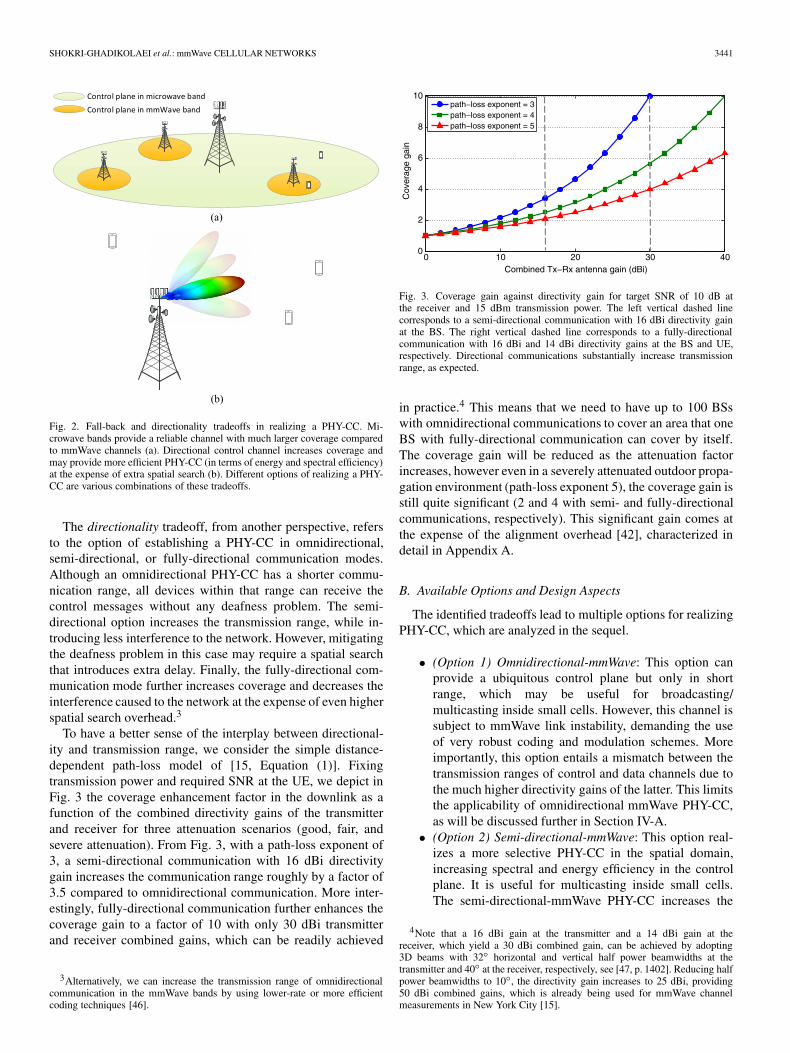
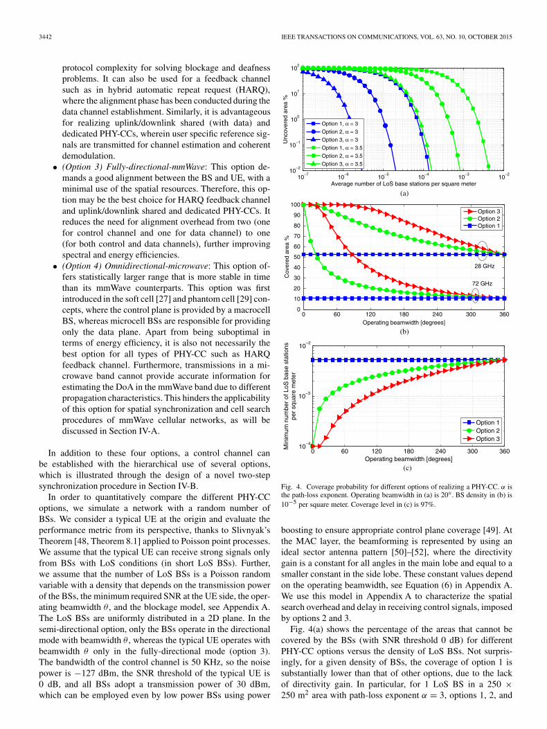
In order to quantitatively compare the different PHY-CCoptions, we simulate a network with a random number ofBSs. We consider a typical UE at the origin and evaluate theperformance metric from its perspective, thanks to Slivnyak’sTheorem [48, Theorem 8.1] applied to Poisson point processes.We assume that the typical UE can receive strong signals onlyfrom BSs with LoS conditions (in short LoS BSs). Further,we assume that the number of LoS BSs is a Poisson randomvariable with a density that depends on the transmission powerof the BSs, the minimum required SNR at the UE side, the oper-ating beamwidth θ , and the blockage model, see Appendix A.The LoS BSs are uniformly distributed in a 2D plane. In thesemi-directional option, only the BSs operate in the directionalmode with beamwidth θ , whereas the typical UE operates withbeamwidth θ only in the fully-directional mode (option 3).The bandwidth of the control channel is 50 KHz, so the noisepower is −127 dBm, the SNR threshold of the typical UE is0 dB, and all BSs adopt a transmission power of 30 dBm,which can be employed even by low power BSs using power
Fig. 4. Coverage probability for different options of realizing a PHY-CC. α isthe path-loss exponent. Operating beamwidth in (a) is 20◦. BS density in (b) is10−5 per square meter. Coverage level in (c) is 97%.
boosting to ensure appropriate control plane coverage [49]. Atthe MAC layer, the beamforming is represented by using anideal sector antenna pattern [50]–[52], where the directivitygain is a constant for all angles in the main lobe and equal to asmaller constant in the side lobe. These constant values dependon the operating beamwidth, see Equation (6) in Appendix A.We use this model in Appendix A to characterize the spatialsearch overhead and delay in receiving control signals, imposedby options 2 and 3.
Fig. 4(a) shows the percentage of the areas that cannot becovered by the BSs (with SNR threshold 0 dB) for differentPHY-CC options versus the density of LoS BSs. Not surpris-ingly, for a given density of BSs, the coverage of option 1 issubstantially lower than that of other options, due to the lackof directivity gain. In particular, for 1 LoS BS in a 250 ×250 m2 area with path-loss exponent α = 3, options 1, 2, and

SHOKRI-GHADIKOLAEI et al.: mmWave CELLULAR NETWORKS 3443
3 cover 63.6%, 99.9%, and 100% of the area, respectively. Amore sparse BS deployment highlights the benefit of havingdirectivity gain both at the BS and at the UE. For instance, withLoS BS density of 2 × 10⁻⁶ (1 BS in a 700 × 700 m2 area),option 3 can cover 99.8% of the area, whereas option 2 canonly support 60% of the area when α = 3. The extra coverageappears at the expense of more complicated alignment betweenthe BS and the UE, as discussed in the next section. A higherattenuation α = 3.5 demands a denser BS deployment for thesame coverage probability. Moreover, we can see that the cov-erage probability is an exponential function of the BS density,as also observed in [53], [54] for wireless sensor networks.
Fig. 4(b) demonstrates the impact of the operatingbeamwidth, and consequently the directivity gain, on the cov-erage probability with α = 3 and BS density 10−5. Increasingθ reduces the coverage monotonically due to the reduced direc-tivity gain. This reduction is more severe at 72 GHz, implyingthat a higher directionality level is required at 72 GHz tocompensate for the higher channel attenuation and provide thesame coverage as at 28 GHz. Recall that we depict coverage ofthe PHY-CC with an SNR threshold of 0 dB. Increasing theSNR threshold leads to a corresponding coverage reduction.With SNR threshold 10 dB, for instance, the coverage for thethree options at 28 GHz would be close to the curves for 72 GHzwith SNR threshold 0 dB in Fig. 4(b), so we omit the former forthe sake of clarity in the figure.
Fig. 4(c) shows the minimum BS density per square meterrequired to ensure 97% coverage of the control channel as afunction of the operating beamwidth. To support 97% coveragelevel, Option 1 requires ultra dense LoS BS density of 5 × 10⁻³
(1 LoS BS in a 14 × 14 m2 area), while Options 2 and 3 mayrequire substantially fewer BSs. For instance, with θ = 30◦,Options 2 and 3 require 1 LoS BS in a 31 × 31 m2 area and1 LoS BS in a 75 × 75 m2 area, respectively.
IV. INITIAL ACCESS AND MOBILITY MANAGEMENT
Initial access and mobility management are fundamentalMAC layer functions that specify how a UE should connectto the network and preserve its connectivity. In this section,we identify the main differences and highlight important designaspects of initial access that should be considered in mmWavecellular networks using an illustrative example, depicted inFig. 5. In the example, we have a macrocell with three micro-cells, two UEs, and one obstacle. UE1 aims at running an initialaccess procedure, whereas UE2 requires multiple handovers.Note that coverage boundaries and possible serving regionsof the BSs, shown by dashed lines, do not necessarily followregular shapes due to randomly located obstacles and reflectors.However, for the sake of simplicity, we neglect this aspect in thefigure.
A. Fundamentals of Initial Access
Once a new UE appears for the very first time, it will start theinitial synchronization process, followed by extraction of sys-tem information. Then, it executes a random access procedureby which the network registers the UE as active. After these
Fig. 5. Initial access and mobility management in mmWave cellular networks.UE1 starts the initial access procedure, and UE2 requires handover. Dashedlines show coverage boundaries (idealized to ease the discussion).
initial access procedures, the UE is connected to the data plane,and is able to transmit and receive actual data.
1) Synchronization and Cell Search: In LTE systems, ac-quiring time–frequency domain synchronization during cellsearch is facilitated by the so-called primary and secondarysynchronization signals, transmitted omnidirectionally in thedownlink [55]. Each UE in the cell is aware a priori of whenand where the synchronization control channel is, and therebycan extract synchronization signals along with cell identity.Hence, current cellular networks use beamforming only af-ter omnidirectional synchronization and cell search procedure.However, as pointed out in [56], performing cell search on anomnidirectional PHY-CC (option 1) while having directivitygain in data transmission causes a mismatch between the rangesat which a link with reasonable data rate can be established andthe range at which a broadcast synchronization signal alongwith cell identity can be detected, known as the problem ofasymmetry in gain in ad hoc networks [46], [57]. For theexample considered in Fig. 3, the data range can be at least4 times larger than the synchronization range with only 30 dBicombined directivity gains even in a severely attenuated prop-agation environment. Therefore, option 1 does not seem aproper candidate for initial cell search procedure. Moreover,the synchronization signals over a microwave band (option 4)cannot provide sufficient information to extract spatial syn-chronization in the mmWave band due to different propagationcharacteristics. Thus, a fully-directional data plane demandsa directional synchronization and cell search procedure in themmWave band using options 2 or 3. These options, how-ever, are subject to the directionality tradeoff, mentioned inSection III-A. They require spatial search that may cause extradelay in obtaining system information at initial cell search.We evaluate the delay characteristics of options 2 and 3 inSection IV-B, after proposing a two-step synchronization pro-cedure, and in Appendix A.
2) Extraction of System Information: System informationincludes cell configurations such as downlink and uplinkbandwidth, frequency band, number of transmit antennas, cellidentity, and random access procedure. LTE embeds systeminformation in the so-called master and system information

3444 IEEE TRANSACTIONS ON COMMUNICATIONS, VOL. 63, NO. 10, OCTOBER 2015
blocks that are transmitted in the physical broadcast channel,dedicated to control signaling, and physical downlink sharedchannel, respectively. While dedicated control channels canbe established with omnidirectional communications, a UEstill needs to decode a directional shared channel to extractsystem information in a mmWave cellular network. This isa fundamental MAC layer issue, which is not a problem inmicrowave cellular networks, as all the rendezvous signaling isdone over omnidirectional control channels (option 4). Deter-mining the exact information that should be transmitted over anomnidirectional control channel at microwave frequencies anda directional control channel at mmWave frequencies dependsheavily on the initial access procedure. In Section IV-B, weprovide preliminary suggestions for an initial access procedurefor mmWave cellular networks.
3) Random Access: At the very beginning, a UE has noreserved channel to communicate with the BS(s), and cansend a channel reservation request using contention-based orcontention-free channel access. The contention-based requests,however, may collide due to simultaneous transmissions inthe same cell, or not be received due to deafness. The com-prehensive analysis of [58] shows that small to modest sizemmWave networks operating with the slotted ALOHA protocol(a simple contention-based strategy) have a very small collisionprobability. In the contention-free scheme, the network definesand broadcasts multiple access signals that uniquely poll theindividual UEs to avoid collisions. These signals should havespatial scheduling information to avoid deafness. Upon decod-ing a signal, each UE knows its uplink parameters: analogbeam, random access preamble, and allocated resource fortransmission of the preamble. Embedding all this informationa priori is a challenging task especially due to the lack of spatialsynchronization at the very beginning. As transmission andreception beamwidths become narrower, a reduced contentionlevel makes contention-based procedures more justifiable thancomplex and wasteful contention-free ones [59].
In the contention-based random access procedure of LTE, aUE triggers a timer after sending a preamble, and if no responseis received from the BS, it retransmits the preamble with anincreased transmission power and/or after a random waiting(backoff) time. In a mmWave cellular network, the deafnessproblem cannot be solved by increasing the transmission poweror waiting for a random backoff time. A UE may unnecessarilyundergo multiple subsequent backoff executions in the deaf-ness condition, resulting in a prolonged backoff time [31]. Tosolve this issue, [31] introduces a novel MAC level collision-notification (CN) signal to distinguish collisions from deafnessand blockage. During the spatial search, if a BS receives energyfrom a direction that is not decodable due to collisions, it sendsback a CN message in that direction.5 After transmitting apreamble, a UE will adopt one of the following three actionsdepending on the received control signal: (1) if a reservationgrant is received before timeout, it starts transmission; (2) if a
5Note that the energy that a BS will receive in a collision state with multiplereceived signals is substantially different from that in the deafness state with noreceived signal. Therefore, a simple hard decision based on the received energy(energy detector) would be enough to distinguish collisions from deafness.
CN message is received before timeout, this is an indicator forcontention in that spatial direction, hence retransmission afterbackoff is used; (3) if no signal is received before timeout, theUE knows that there is either deafness or blockage in this di-rected spatial channel, so it tries to investigate another directionor adjust the transmission beamwidth instead of executing anunnecessary backoff.
B. Two-Step Synchronization and Initial Access
In this section, we utilize directional cell search and suggesta two-step synchronization procedure, followed by extractionof system information and random access procedures. In thefirst step, the macrocell BS broadcasts periodic time–frequencysynchronization signals over an omnidirectional microwavecontrol channel (option 4). When a new entity (either a UEor a microcell BS) turns on its radios, it first looks at the om-nidirectional synchronization control channel, trying to detectthe time–frequency synchronization signals. Here, the existingsynchronization signals and procedure of LTE may be reused.After the first step, all entities in the macrocell, includingmicrocell BSs and UEs, will be synchronized in time andfrequency.6 Moreover, the macrocell BS embeds some infor-mation about the cell in these time–frequency synchronizationsignals, for instance, its ID. In the second step, the microcellBSs perform a periodic spatial search using a sequence of pilottransmissions at mmWave frequencies. Upon receiving a pilot,the UE finds the remaining system information along with acoarse estimation of DoA, thanks to its multiple antennas. Inthis direction, the UE feeds back a preamble in a predeterminedpart of the time–frequency domain for which the correspondingmicrocell BS is receiving preambles. Note that the second phasecan be initiated in semi- or fully-directional mode, leading tosmaller collision probability compared to the omnidirectionalcase. The proposed two-step procedure enables us to supportboth cell-centric and UE-centric designs. In the former, theBSs periodically initiate both steps of the procedure, similar toexisting cellular networks. In the latter, the second step (spatialsynchronization) is triggered by the UE (on-demand), insteadof the network.
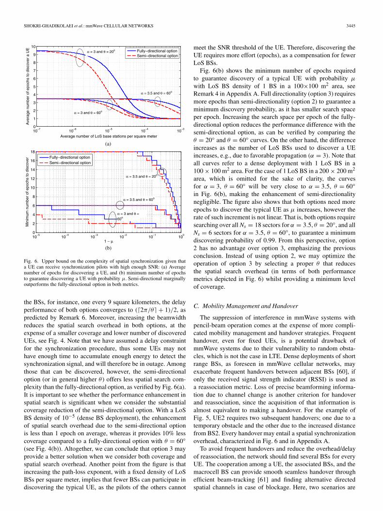
In Appendix A, we have characterized the delay performanceof spatial synchronization for options 2 and 3. We consider thesame model for LoS BSs, whose synchronization pilots can bereceived by a typical UE, with the same initial parameters asin Section III-B. Individually, every microcell BS divides a 2Dspace into Ns = �2π/θ� sectors, sorts them in a random order,and sends synchronization pilots toward sectors sequentially,that is, one sector per epoch. Upon receiving a pilot with highenough SNR, the UE extracts DoA along with other systeminformation. Fig. 6(a) shows the average number of epochsrequired for discovering the UE for semi- and fully-directionaloptions as a function of LoS BS density per square meter.The spatial search overhead for the semi-directional option isalways less than that for the fully-directional one, as predictedby Remark 5 in Appendix A. For a very sparse deployment of
6Some mapping, which may be as simple as some scalars, is necessary tomap time–frequency synchronization in microwave band into mmWave band.
SHOKRI-GHADIKOLAEI et al.: mmWave CELLULAR NETWORKS 3445
Fig. 6. Upper bound on the complexity of spatial synchronization given thata UE can receive synchronization pilots with high enough SNR: (a) Averagenumber of epochs for discovering a UE, and (b) minimum number of epochsto guarantee discovering a UE with probability μ. Semi-directional marginallyoutperforms the fully-directional option in both metrics.
the BSs, for instance, one every 9 square kilometers, the delayperformance of both options converges to (�2π/θ� + 1)/2, aspredicted by Remark 6. Moreover, increasing the beamwidthreduces the spatial search overhead in both options, at theexpense of a smaller coverage and lower number of discoveredUEs, see Fig. 4. Note that we have assumed a delay constraintfor the synchronization procedure, thus some UEs may nothave enough time to accumulate enough energy to detect thesynchronization signal, and will therefore be in outage. Amongthose that can be discovered, however, the semi-directionaloption (or in general higher θ ) offers less spatial search com-plexity than the fully-directional option, as verified by Fig. 6(a).It is important to see whether the performance enhancement inspatial search is significant when we consider the substantialcoverage reduction of the semi-directional option. With a LoSBS density of 10−5 (dense BS deployment), the enhancementof spatial search overhead due to the semi-directional optionis less than 1 epoch on average, whereas it provides 10% lesscoverage compared to a fully-directional option with θ = 60◦(see Fig. 4(b)). Altogether, we can conclude that option 3 mayprovide a better solution when we consider both coverage andspatial search overhead. Another point from the figure is thatincreasing the path-loss exponent, with a fixed density of LoSBSs per square meter, implies that fewer BSs can participate indiscovering the typical UE, as the pilots of the others cannot
meet the SNR threshold of the UE. Therefore, discovering theUE requires more effort (epochs), as a compensation for fewerLoS BSs.
Fig. 6(b) shows the minimum number of epochs requiredto guarantee discovery of a typical UE with probability μ
with LoS BS density of 1 BS in a 100×100 m2 area, seeRemark 4 in Appendix A. Full directionality (option 3) requiresmore epochs than semi-directionality (option 2) to guarantee aminimum discovery probability, as it has smaller search spaceper epoch. Increasing the search space per epoch of the fully-directional option reduces the performance difference with thesemi-directional option, as can be verified by comparing theθ = 20◦ and θ = 60◦ curves. On the other hand, the differenceincreases as the number of LoS BSs used to discover a UEincreases, e.g., due to favorable propagation (α = 3). Note thatall curves refer to a dense deployment with 1 LoS BS in a100 × 100 m2 area. For the case of 1 LoS BS in a 200 × 200 m2
area, which is omitted for the sake of clarity, the curvesfor α = 3, θ = 60◦ will be very close to α = 3.5, θ = 60◦in Fig. 6(b), making the enhancement of semi-directionalitynegligible. The figure also shows that both options need moreepochs to discover the typical UE as μ increases, however therate of such increment is not linear. That is, both options requiresearching over all Ns = 18 sectors for α = 3.5, θ = 20◦, and allNs = 6 sectors for α = 3.5, θ = 60◦, to guarantee a minimumdiscovering probability of 0.99. From this perspective, option2 has no advantage over option 3, emphasizing the previousconclusion. Instead of using option 2, we may optimize theoperation of option 3 by selecting a proper θ that reducesthe spatial search overhead (in terms of both performancemetrics depicted in Fig. 6) whilst providing a minimum levelof coverage.
C. Mobility Management and Handover
The suppression of interference in mmWave systems withpencil-beam operation comes at the expense of more compli-cated mobility management and handover strategies. Frequenthandover, even for fixed UEs, is a potential drawback ofmmWave systems due to their vulnerability to random obsta-cles, which is not the case in LTE. Dense deployments of shortrange BSs, as foreseen in mmWave cellular networks, mayexacerbate frequent handovers between adjacent BSs [60], ifonly the received signal strength indicator (RSSI) is used asa reassociation metric. Loss of precise beamforming informa-tion due to channel change is another criterion for handoverand reassociation, since the acquisition of that information isalmost equivalent to making a handover. For the example ofFig. 5, UE2 requires two subsequent handovers; one due to atemporary obstacle and the other due to the increased distancefrom BS2. Every handover may entail a spatial synchronizationoverhead, characterized in Fig. 6 and in Appendix A.
To avoid frequent handovers and reduce the overhead/delayof reassociation, the network should find several BSs for everyUE. The cooperation among a UE, the associated BSs, and themacrocell BS can provide smooth seamless handover throughefficient beam-tracking [61] and finding alternative directedspatial channels in case of blockage. Here, two scenarios are

3446 IEEE TRANSACTIONS ON COMMUNICATIONS, VOL. 63, NO. 10, OCTOBER 2015
TABLE ICOMPARISON OF DIFFERENT REALIZATIONS OF PHY-CC
foreseeable. A UE may adopt multi-beam transmissions towardseveral base (relay) stations, so it will receive data from severaldirections at the same time, but with a corresponding SNR lossfor each beam, if we consider a fixed total power budget. Forthe example considered in Fig. 5, smooth handover, robustnessto blockage, and continuous connectivity is available if UE2is served by both BS2 and BS3. The price, however, is a3 dB SNR loss for each beam, on average, as well as the needfor cooperation and joint scheduling between BS2 and BS3 forserving UE2. Alternatively, a UE may be associated to severalbase (relay) stations, but only one of them is the serving BSwhereas the others are used as backup. This scenario mitigatesjoint scheduling requirements. Besides, backup connectionsenable switching without extra delay if the alignment andassociation to backup BSs are done periodically. In light of auser-centric design, the macrocell BS can record all connectionsof UE2, predict its mobility, give neighboring BSs some sideinformation indicating when UE2 is about to make a handover,so they can better calibrate the directed channel and be readyfor handover. Altogether, UE2 is served by either BS2 or BS3,however it is connected to both BSs for fast switch operation.
To facilitate handover negotiations, a reliable PHY-CC inthe microwave band (option 4) seems an appropriate choice.Periodic connection checks between UEs and associated BSscan be done using more efficient PHY-CCs such as option 3.Table I summarizes the pros and cons of different realizationsof the control channel with possible application areas.
V. RESOURCE ALLOCATION AND
INTERFERENCE MANAGEMENT
In order to leverage the special propagation characteristicsand hardware requirements of mmWave systems, we suggestto migrate from the current interference-limited to a noise-limited architecture, from the current static to a dynamic cell
definition, and from the current cell-centric to a user-centricdesign, all made possible under a proper software definedwireless network.
A. Channelization
A key decision in MAC layer design is how to divide thephysical resources in smaller units, called resource blocks.Although LTE defines a resource block as a portion of thetime–frequency domain, directional transmission in mmWavecellular networks motivates to supplement the definition ofresource block with a spatial dimension, leading to a blockin the time–frequency–space domain. Proper utilization ofsuch a resource block with a digital beamforming procedurerequires precise CSI, imposing a large complexity during thepilot transmission phase, as stated in Section II-C. Instead,a hybrid beamforming technique provides a promising lowoverhead solution. Defining a group as a set of UEs that are non-distinguishable in the transmitted beam, the BS groups UEstogether with one analog beamformer, as shown in Fig. 7(b),and serves every group with one analog beamforming vector[62]. Clearly, a macro BS can also group micro BSs and servethem together using a mmWave wireless backhaul link (in-bandbackhauling [63]). In fact, the analog beamformer partiallyrealizes the spatial part of the new three dimensional resourceblocks. Digital beamforming provides further spatial gain bymultiplexing within a group, which is affordable due to asubstantial reduction in the dimension of the effective channel,that is, the channel from a digital beamformer perspective [62].
B. Scheduling
The time–frequency–space resources with narrow-beam op-eration allow a large number of concurrent transmissions andthus a high area spectral efficiency, measured in bits/s/Hz/m2.

SHOKRI-GHADIKOLAEI et al.: mmWave CELLULAR NETWORKS 3447
Fig. 7. Scheduling scenarios in mmWave cellular networks: (a) traditional time–frequency-dependent scheduling, (b) time–frequency–space-dependentscheduling using semi-directional communications, (c) time–frequency–space-dependent scheduling using semi-directional communications and relay stations,(d) time–frequency–space-dependent scheduling using fully-directional communications. The network throughput in scenarios (a) to (d) is 60, 120, 120, and240 resource blocks, respectively.
In the following, we discuss scheduling based on the hybridbeamforming structure, and leave the full digital beamformingoption for future studies. Depending on the directionality level,three scheduling scenarios are foreseeable, see Fig. 7. In orderto have insights and an illustrative comparison among differentscenarios, and with no loss in generality, we elaborate on anexample with the following assumptions: (1) the BS has 60resource blocks in a slot, (2) there is no multiplexing inside abeam, (3) there is no inter-cell interference, (4) all UEs receivethe same number of resource blocks (max-min scheduling), and(5) the base and relay stations have 4 RF chains (analog beams)each.
1) Omnidirectional Communications: Traditionally, thescheduling procedure in cellular networks is designed based onthe assumption of omnidirectional communication, which leadsto an orthogonal use of time–frequency resource blocks throughtime–frequency–dependent scheduling inside a cell. The mul-tiplexing gain, which depends on the channel rank, furtherincreases the spectral efficiency (see Fig. 7(a)). The elementarydirectional communication capabilities with a limited numberof antennas, as in LTE, are not applicable to mmWave networks
due to the large number of antennas both at the BS and at theUEs. For the example considered, the BS (together with therelay station) can inject up to 60 resource blocks per slot inthe cell, which is the maximum achievable network throughput.Considering 10 single antenna UEs in the cell, each UE canreceive up to 6 resource blocks.
2) Semi-Directional Communications: Considering a largenumber of antennas, with a limited number of RF chains,the BS can group UEs together based on the second orderstatistics of the channel and serve every group of UEs thathave similar covariance matrix with one analog beamformingvector [62], [64]. To reuse time–frequency resource blocks fordifferent groups, made by different analog beamformers, oneneeds a time–frequency–space-dependent scheduling. Hence,the design of analog beamformers is a fundamental MAClayer problem, since analog beamforming vectors are spatialresources that should be allocated to UEs together with timeand frequency resources. However, we may have differenttime horizons over which spatial and time–frequency resourcesshould be scheduled. Time–frequency scheduling should berecalculated after every channel coherence time and bandwidth,

3448 IEEE TRANSACTIONS ON COMMUNICATIONS, VOL. 63, NO. 10, OCTOBER 2015
whereas spatial scheduling may be recalculated after a mean-ingful change in the covariance matrix of the channel, which isless frequent compared to the former. We use this property inthe next subsections.
The new scheduling decisions may be complicated due to thecomplex interplay between different groups. A UE may belongto several groups in order to increase connection robustnessto the blockages and provide smooth handover among groups,for instance, UE1 in Fig. 7(c) is in G2 and G3. In this case,time–frequency-dependent scheduling inside G2 depends onthat of G3, as they have UE1 in common, demanding coop-eration between the BS and the relay station in serving UE1.In other words, scheduling for G2 is correlated to that of G3.However, from a spectral efficiency perspective, decorrelatingdifferent groups increases the reuse factor,7 thereby enhancingspectral efficiency. This introduces a tradeoff between connec-tion robustness and spectral efficiency, which is affected by thenumber of groups, i.e., the available degrees of freedom. Notethat with single antenna UEs (semi-directional communicationscenario), there is a one-to-one mapping between being spa-tially close to each other and belonging to the same group [62],[64], [65]. Therefore, the number of groups is dictated by twofactors: (1) the number of RF chains and (2) the number ofcolocated UEs (UE clusters). While the former is a fundamentalconstraint, the latter can be relaxed if we incorporate fully-directional communications, since multiple antennas at the UEsenable control of the grouping from the UEs sides.
In the example, the BS can reuse all 60 resource blocksfor G1 and G2. For the groupings depicted in Fig. 7(b) and(c) and without multiplexing gain inside groups, the networkthroughput is 120 resource blocks due to the spatial divisiongain at the BS side, which is twice that with omnidirectionalcommunications. Each single-antenna UE in G1 and G2 (G3)receives 15 and 10 resource blocks, respectively. Clearly, eventhough fairness is ensured per group, it has been violated atthe macro level, due to the geographical (spatial) distributionof the UEs. Therefore, spatial grouping may violate fairness,even though it can potentially increase network throughput.The use of reflectors and relay stations is instrumental toform new groups and attain a good tradeoff among throughputenhancement, fair scheduling, and high connection robustness.
3) Fully-Directional Communications: The existence ofmultiple antennas at the UEs promises spatial division gainsat the UEs, which substantially increases the degrees of free-dom compared to the semi-directional communication scenariowhere such a gain is available only at one entity of the network,the BS. The degrees of freedom can be further increased byenvisioning multi-beam operation ability at the UEs8 [66].
Managing the beamforming capabilities of the UEs, theBS can manipulate the effective channel that it will observe
7The spatial reuse can be improved both in the sense that more BSs can beactive simultaneously and in the sense that one BS can use more beams. Theformer is clear from Fig. 7(c). For the latter, replacing the relay station with areflector, the BS serves G3 using a new beam, pointed toward the reflector.
8Multi-beam operation enables coherent combining of the strongest signalsreceived from several distinct spatially-pointed beams at the UE. This coherentcombination can give up to 24 dB link budget improvement at 28 GHz [66].
and make it a proper channel9 for scheduling purposes. Thenotion of grouping needs an extension to include the impact ofmultiple antenna processing capabilities at the UEs. ColocatedUEs do not necessarily belong to the same group, as they canmatch their beams to different beams offered by the BS (ordifferent BSs) and be served in different groups by differentanalog beamformers. In Fig. 7(d), for instance, fully-directionalcommunication makes G2 and G3 uncorrelated if UE1 pointstoward the BS and UE2 uses a beam toward the relay station,even though UE1 and UE2 are still colocated. This impliesthat all time–frequency resource blocks of G2 can be reusedinside G3 without any joint scheduling. Moreover, UEs ofG1 can be served separately due to spatial division gain atthe UEs. With proper scheduling, the number of RF chainsin the network infrastructure (base/relay stations) will be theonly limiting factor, reflecting a tradeoff between hardware costand achievable spectral efficiency. For dense BS deployment,capacity enhancement can be easily achieved by adding moreRF chains, rather than more BSs. Hence, proper schedulingalgorithms for mmWave cellular networks should be scalablewith respect to the number of RF chains.
In the example, the BS can make four groups (three UEsand one relay station), and the relay station serves only UE2(5 groups in total). The BS together with the relay station canreuse all 60 resource blocks for every multi-antenna UE. Thenetwork throughput is 240 resource blocks, twice that withsemi-directional communications. This is due to spatial divisiongain at the multi-antenna UEs and no extra hardware com-plexity at the BS. Another important note is that the increaseddegrees of freedom in grouping have solved the above unfair-ness in the resource allocation, even though the UEs are stillcolocated. In Appendix B, we formulate an optimization prob-lem for resource allocation in order to improve the throughput-fairness tradeoff with a minimum QoS level guarantees.
C. Interference Management
In general, there are three types of interference that shouldbe managed:
1) Intra-Cell Interference: This is the interference amongUEs within a cell. Using proper scheduling and beamformingdesign, the intra-cell interference can be mitigated. Pencil-beam operation substantially facilitates the intra-cell interfer-ence management strategy, due to spatial orthogonality of thedirected channels of different UEs [58]. Intra-group interfer-ence, namely interference among UEs within a group, can bealso mitigated using similar techniques.
2) Inter-Cell Interference: The interference among differentcells is called inter-cell interference. It is a challenge in tradi-tional cellular networks, especially at the cell edges, where thereuse of the same resource block in adjacent cells causes stronginterference. Inter-cell interference coordination, which is usedin LTE, may not be necessary in mmWave cellular networks,since the scheduling based on time–frequency–space resource
9The word “proper channel” is intentionally left fuzzy, since it depends onthe ultimate goal of the beamforming at the BS, which may not be the same inall situations.

SHOKRI-GHADIKOLAEI et al.: mmWave CELLULAR NETWORKS 3449
blocks along with fully-directional communication inherentlysignificantly reduces the inter-cell interference, as illustratedin Fig. 1(a). In the case of rare interference, the UEs/BSs caninitiate an on-demand interference management strategy [31].Also, proper design of analog beamforming at the transmitterand the receiver can minimize inter-group interference.
3) Inter-Layer Interference: It refers to interference amongdifferent layers, macro, micro, femto, and pico, which may bemore severe compared to inter-cell interference among cells ofthe same layer due to directional communications.
It is worth mentioning that the role of interference is stillprominent in omnidirectional control channels, which may needto be used for broadcasting, synchronization, and even channelestimation. This demands careful design of the pilots andcontrol messages that aim at transmitting in omnidirectionalcommunication mode to avoid inefficient utilization of theavailable resources, e.g., see the pilot contamination problemin massive MIMO [67], [68].
D. Dynamic Cell
Most of the current standards define a cell by the set ofUEs that are associated using a minimum-distance rule, whichleads to non-overlapping Voronoi tessellation of the servingarea of every BS, exemplified by the well-known hexagonalcells [69], [70]. The minimum-distance rule leads to a simpleassociation metric based on the reference signal received power(RSRP) and RSSI. However, the traditional RSRP/RSSI-basedassociation may become significantly inefficient in the presenceof non-uniform UE spatial distribution, and of heterogeneousBSs with a different number of antenna elements and differenttransmission powers [60], [69]. This association entails anunbalanced number of UEs per cell, which limits the availableresources per UE in highly populated cells, irrespective ofindividual signal strengths, while wasting them in sparse ones.This is exacerbated by the directionality in mmWave systems,where the whole system becomes noise-limited, and it becomespointless to use an association metric suited for an interference-limited homogenous system. The main disadvantage of the cur-rent static definition of a cell, as a predetermined geographicalarea covered by a BS, is that the static cell formation is inde-pendent of the cell load as well as of the UEs’ capabilities.10
In fact, three parameters should affect cell formation: (i) UEtraffic demand, (ii) channel between UE and BSs, and (iii)BSs loads. Minimum-distance (RSRP/RSSI-based) associationonly considers the second parameter, such that reassociationis needed if this parameter is changed, which is inefficient inmmWave systems [60].
With the massive number of degrees of freedom that fully-directional communication offers and possible MAC layer ana-log beamforming, we can define a dynamic cell as a set of notnecessarily colocated UEs that are served by the same analogbeamformer of the BS and dynamically selected to improvesome objective function. Upon any significant fluctuations ofthe above three parameters, dynamic cell redefinition may be
10Note that the state-of-the-art soft and phantom cell concepts have theseproblems as well.
required. To this end, we need a full database in the macrocellBS, recording dynamic cell formations, UEs’ traffic demands,their quality of service levels, and their connectivity to theneighboring BSs. Depending on the UEs’ demands, microcellBSs dynamically group UEs together and form new cells so that(i) individual UE’s demands are met (QoS provisioning), (ii) thetradeoff between macro-level fairness and spectral efficiencyis improved, e.g., through proportional fair resource allocation(network utility maximization), and (iii) every UE is categorizedin at least two groups, to guarantee robustness to blockage(connection robustness). Two colocated UEs may belong totwo different cells if their demands cannot be fully served withresource sharing inside a cell and if there exist proper directedspatial channels to form two independent cells. Moreover, anew UE is not necessarily served by a geographically closeBS, if this violates the QoS of a UE that is already served bythat BS. While serving a UE with a less-loaded but fartherBS is not a good choice in interference-limited traditionalcellular networks, it is feasible (and in fact desirable) in properresource allocation based on fully-directional communication.All this may entail a substantial modification/extension ofthe methodology of cellular network analysis [48], [70]–[74]in general and mmWave cellular networks in particular [52],[75], as the main assumptions made in those frameworks ofVoronoi serving regions do not hold. The notion of dynamic cellrevolutionizes traditional cell-centric design and introduces anew user-centric design paradigm. This is especially importantfor uniform quality of experience provisioning throughout thenetwork, which is one of the main goals in 5G.
In the following, we clarify the dynamic cell concept withan illustrative example. Consider a network with four UEs andtwo microcell BSs. BS1 serves colocated UE1 and UE2, andBS2 serves colocated UE3 and UE4. Therefore, we have twocells: one created by UE1 and UE2, and the other by UE3and UE4. Assume that the traffic demands of UE1 and UE2increase so that BS1 is no longer able to serve them both, whileBS2 can serve one of them together with its own UEs. In thiscase, BS1 broadcasts a cell redefinition request, and a dynamiccell configuration reassociates UE2 from the first to the sec-ond cell. Now, the first cell contains only UE1, and the sec-ond cell contains UE2, UE3, and UE4.11 The reconfigurationis done by changing the analog beamforming vectors of theBSs and UEs. The reconfiguration process can be managedat a macrocell BS that covers both BS1 and BS2, makingthe dynamic cell concept compatible with software definednetworking and centralized radio network control [32], [76].The benefit of dynamic cell formation depends heavily on theinterference level, as pointed out partially in [69]. High direc-tionality in mmWave systems with pencil-beam operation is aunique advantage, as microwave networks with omnidirectionaloperation are interference-limited.
To evaluate the performance gain due to the new degreesof freedom in mmWave networks, we simulate a network with2 BSs and 30 UEs, distributed in 1 square kilometer. We consider
11Note that dynamic cell formation is fundamentally different from reasso-ciation after a handover, as the former may be triggered without any change inthe environment due to mobility or blockage.

3450 IEEE TRANSACTIONS ON COMMUNICATIONS, VOL. 63, NO. 10, OCTOBER 2015
Fig. 8. Example of the optimal association. Squares represent BSs, and stars are UEs. (a) Omnidirectional communication; (b) semi- and fully-directionalcommunications with 3 RF chains at every BS; (c) semi-directional communication with 12 RF chains at every BS, and (d) fully-directional communication with12 RF chains at every BS. Solid red lines show association to one RF chain of BS1. Dashed green lines represent association to one RF chain of BS2.
a mmWave wireless channel with path-loss exponent α = 3,and adopt the same initial parameters as in Section III-B. InAppendix B, cell formation is posed as an optimization problemaimed to ensure micro- and macro-level fairness with a prede-fined minimum rate for every UE. Given a network topology,the solution of optimization problem (9) in Appendix B givesthe optimal association, resource sharing within every analogbeam, operating beamwidths, and boresight angles of BSs aswell as UEs. We conducted 10 experiments to evaluate theimpact of directionality on the network performance in termsof sum rate in bps/Hz, maximum of the minimum rate of a UEin bps/Hz, and fairness using Jain’s fairness index [77]. In allthe experiments, we considered a summation over logarithmicfunctions for the network utility maximization formulated in(9) in Appendix B to guarantee fairness, as pointed out inProposition 1 in Appendix B. Furthermore, we assume that BSsand UEs can respectively make beams as narrow as 5◦ and 10◦,if required. Experiments 1–3 are done as follows: the networktopology and geometry is fixed, we consider only one RF chainfor every UE, the number of RF chains per BS is varied,and we find the optimal solution of (9), which includes theoptimal association. Experiments 4–6 are done as follows: theassociations are fixed to those obtained in experiments 1–3, andwe use Remark 7 in Appendix B to find a sub-optimal solutionof optimization problem (9) for semi-directional communica-tions. Finally, in experiments 7–9, we solve optimization prob-lem (9) for semi-directional communications, whose solution
includes the optimal association. The last experiment showsthe omnidirectional performance, evaluated using Remark 8in Appendix B. For benchmarking purposes, we also show theoptimal association for one random topology in Fig. 8, wheresquares represent BSs, and stars are UEs, solid red lines showassociation to one RF chain of BS1, and dashed green linesrepresent association to one RF chain of BS2. In particular,Fig. 8(a), (b), (c), and (d) represents the optimal associationsfor experiments 10, 7, 9, and 3, respectively.
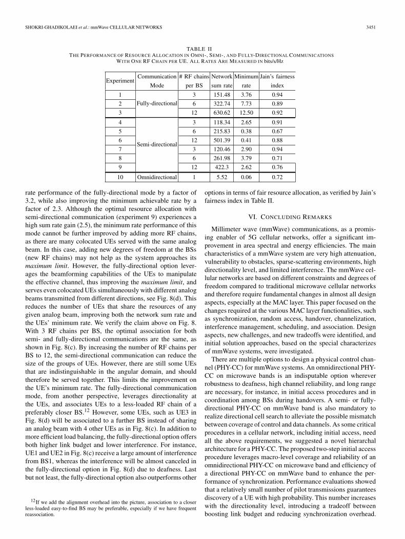
Table II shows the performance in all experiments, averagedover 10 random topologies. In general, the fully-directionalmode outperforms other modes, as directionality improves thelink budget on one side and reduces the interference on theother. In particular, compared to the omnidirectional modein experiment 10, we observe a sum rate enhancement byfactors of 113 and 75 in experiments 3 and 9, respectively.These enhancements are even more significant in terms of theminimum offered spectral efficiency, that is, 207 and 43 timesin experiments 3 and 9, compared to experiment 10. ComparingFig. 8(a) to Fig. 8(c) and (d), we can see that many UEs haveto share the available resources in the omnidirectional commu-nication, whereas in the semi- and fully-directional cases theyshare the available resources among significantly fewer UEs.Another point is that the increase of the number of RF chainsadds new degrees of freedom, leading to further improvementin the sum and the minimum rates. For instance, increasingthe number of RF chains by a factor of 4 improves the sum
SHOKRI-GHADIKOLAEI et al.: mmWave CELLULAR NETWORKS 3451
TABLE IITHE PERFORMANCE OF RESOURCE ALLOCATION IN OMNI-, SEMI-, AND FULLY-DIRECTIONAL COMMUNICATIONS
WITH ONE RF CHAIN PER UE. ALL RATES ARE MEASURED IN bits/s/Hz
rate performance of the fully-directional mode by a factor of3.2, while also improving the minimum achievable rate by afactor of 2.3. Although the optimal resource allocation withsemi-directional communication (experiment 9) experiences ahigh sum rate gain (2.5), the minimum rate performance of thismode cannot be further improved by adding more RF chains,as there are many colocated UEs served with the same analogbeam. In this case, adding new degrees of freedom at the BSs(new RF chains) may not help as the system approaches itsmaximum limit. However, the fully-directional option lever-ages the beamforming capabilities of the UEs to manipulatethe effective channel, thus improving the maximum limit, andserves even colocated UEs simultaneously with different analogbeams transmitted from different directions, see Fig. 8(d). Thisreduces the number of UEs that share the resources of anygiven analog beam, improving both the network sum rate andthe UEs’ minimum rate. We verify the claim above on Fig. 8.With 3 RF chains per BS, the optimal association for bothsemi- and fully-directional communications are the same, asshown in Fig. 8(c). By increasing the number of RF chains perBS to 12, the semi-directional communication can reduce thesize of the groups of UEs. However, there are still some UEsthat are indistinguishable in the angular domain, and shouldtherefore be served together. This limits the improvement onthe UE’s minimum rate. The fully-directional communicationmode, from another perspective, leverages directionality atthe UEs, and associates UEs to a less-loaded RF chain of apreferably closer BS.12 However, some UEs, such as UE3 inFig. 8(d) will be associated to a further BS instead of sharingan analog beam with 4 other UEs as in Fig. 8(c). In addition tomore efficient load balancing, the fully-directional option offersboth higher link budget and lower interference. For instance,UE1 and UE2 in Fig. 8(c) receive a large amount of interferencefrom BS1, whereas the interference will be almost canceled inthe fully-directional option in Fig. 8(d) due to deafness. Lastbut not least, the fully-directional option also outperforms other
12If we add the alignment overhead into the picture, association to a closerless-loaded easy-to-find BS may be preferable, especially if we have frequentreassociation.
options in terms of fair resource allocation, as verified by Jain’sfairness index in Table II.
VI. CONCLUDING REMARKS
Millimeter wave (mmWave) communications, as a promis-ing enabler of 5G cellular networks, offer a significant im-provement in area spectral and energy efficiencies. The maincharacteristics of a mmWave system are very high attenuation,vulnerability to obstacles, sparse-scattering environments, highdirectionality level, and limited interference. The mmWave cel-lular networks are based on different constraints and degrees offreedom compared to traditional microwave cellular networksand therefore require fundamental changes in almost all designaspects, especially at the MAC layer. This paper focused on thechanges required at the various MAC layer functionalities, suchas synchronization, random access, handover, channelization,interference management, scheduling, and association. Designaspects, new challenges, and new tradeoffs were identified, andinitial solution approaches, based on the special characterizesof mmWave systems, were investigated.
There are multiple options to design a physical control chan-nel (PHY-CC) for mmWave systems. An omnidirectional PHY-CC on microwave bands is an indisputable option whereverrobustness to deafness, high channel reliability, and long rangeare necessary, for instance, in initial access procedures and incoordination among BSs during handovers. A semi- or fully-directional PHY-CC on mmWave band is also mandatory torealize directional cell search to alleviate the possible mismatchbetween coverage of control and data channels. As some criticalprocedures in a cellular network, including initial access, needall the above requirements, we suggested a novel hierarchalarchitecture for a PHY-CC. The proposed two-step initial accessprocedure leverages macro-level coverage and reliability of anomnidirectional PHY-CC on microwave band and efficiency ofa directional PHY-CC on mmWave band to enhance the per-formance of synchronization. Performance evaluations showedthat a relatively small number of pilot transmissions guaranteesdiscovery of a UE with high probability. This number increaseswith the directionality level, introducing a tradeoff betweenboosting link budget and reducing synchronization overhead.

3452 IEEE TRANSACTIONS ON COMMUNICATIONS, VOL. 63, NO. 10, OCTOBER 2015
Comprehensive performance analysis of different PHY-CC op-tions is an interesting topic for future studies.
Directional operation with pencil beams, which is mandatoryto boost link budget in mmWave band, provides a large numberof degrees of freedom to form different cells and allocate re-sources, while significantly simplifying intra- and inter-cell in-terference cancelation. As stated in Section V-B, leveraging thepotential of mmWave systems to improve the complex tradeoffsamong throughput enhancement, fair scheduling, and high con-nection robustness demands revisiting the current interference-limited architecture. An example was provided to highlight thata proper scheduling with fully-directional communication witha limited number of RF chains leads to a significant throughputgain over existing omnidirectional operation, while improvingthe fairness among the UEs. The performance of both semi- andfully-directional operations improves with the number of RFchains per BS, but in a saturating manner. The former generallyfaces the saturation point for a small number of RF chains,while the latter will still benefit from having more RF chains,as new RF chains open new opportunities to redefine cells soas to better balance the total load of the network. This will leadto a significant improvement in the network sum rate as wellas enhancements in the minimum rate offered to a UE and inJain’s fairness index.
Software defined wireless networking as well as relayingtechniques must be considered as primary building blocks innext generation cellular networks for both access and back-haul, since they can provide more uniform quality of serviceby offering efficient mobility management, smooth handoveroperation, load balancing, and indoor-outdoor coverage. Asthe system goes to a noise-limited regime, resource allocationand interference management procedures will be simplified,whereas connection establishment (initial access) and recovery(handover) become complicated. As recently pointed out, forinstance, in [42], [58], [78]–[82], the noise-limited regime alsofacilitates concurrent transmissions and increases the benefitsof device-to-device (D2D) and cognitive communications un-derlying a cellular networks. At the same time, a noise-limitedsystem simplifies the required MAC layer intelligence forspectrum sharing and inter-network interference avoidance. Aninteresting topic for future studies is in which conditions (forinstance, in terms of UE and BS densities, transmission powers,operating beamwidths, and UE traffic) we are in the noise-limited regime. The answer to this fundamental question willshed light on the complexity of various MAC layer functions.
APPENDIX ASPATIAL SEARCH OVERHEAD
In this appendix, we compute an upper bound for the delayof spatial search using options 2 and 3 of Section III-B. Tothis end, we assume that there are nb BSs whose pilots can bereceived with high enough SNR at a typical UE, located at theorigin. The UE and all BSs are aware of the time–frequencyportions over which the directional synchronization pilots aretransmitted, thanks to the proposed two-step synchronizationprocedure. All the BSs transmit pilot signals with the samepower p and beamwidth θ . We only consider a 2D plane,
so there are Ns = �2π/θ� non-overlapping sectors that a BSshould search over to find the typical UE. The upper bound isset by assuming that each BS randomly selects a new sector,among the Ns sectors with uniform distribution, to searchusing pilot transmission. In semi-directional mode, the UE hasomnidirectional reception. In fully-directional mode, the UEis assumed to listen in one direction while the BSs do thesearch. A joint search by UE and BS is left as future work. Forthe sake of simplicity, we only count the BSs with LoS links.Thanks to this assumption, we end up with tractable closed-form expressions that give new insights on the overhead of thespatial search required by options 2 and 3. Note that we stillfind an upper bound on the delay performance, because theUE may receive a pilot of a close NLoS BS, even though thisevent does not happen frequently due to very high attenuationwith every obstacle. Supposing that the process of obstaclesforms a random shape process, for instance, a Boolean schemeof rectangles as considered in [83], and under some furtherassumptions such as independent blockage events [52], we canassume that the number of LoS BSs nb is a Poisson randomvariable with mean ρ, which depends on the average LoS rangeof the network [52], [83]. Note that ρ is equal to the density ofLoS BSs per square meter, denoted by ρu, times the effectivearea, whose value depends on the option chosen to realize thephysical control channel and will be characterized later. Further,the LoS BSs are located uniformly in the 2D plane. In thefollowing, we compute the probability that the typical UE canbe found after ne epochs of pilot transmission for an arbitrarydensity of LoS BSs ρ. We then characterize ρ as a functionof the transmission power and beamwidth for both semi- andfully-directional case.
The UE can be discovered if and only if there is at least oneBS, that is, m≥1, which happens with probability 1 − e−ρ [53].Under this condition, we denote by Pr[ne = n, nb = m|m ≥ 1]the joint probability of discovering the typical UE at epoch nand having m LoS BSs, given m ≥ 1. Pr[nb = m|m ≥ 1] fol-lows a zero-truncated Poisson distribution [84]. Given m ≥ 1,the UE will be discovered by epoch n (cumulative distributionfunction), with probability Pr[ne ≤ n|nb = m, m ≥ 1], if it fallsin at least one of the n sectors that any BS has investigated.Since each BS chooses uniformly and independently n out ofNs sectors, we have
Pr[ne ≤ n|nb = m, m ≥ 1] = 1 −(
1 − n
Ns
)m
.
The probability mass function is
Pr[ne = n|nb = m, m ≥ 1] =(
1 − n − 1
Ns
)m
−(
1 − n
Ns
)m
for n>0. Therefore, we can find Pr[ne =n, nb =m|m≥1] in(2), and consequently Pr[ne =n|m≥1] in (3), shown at the bot-tom of next page. For (�) in (3), we used the Taylor series of theexponential function. Using (3), we can derive closed-form ex-pressions for several interesting performance metrics. Recallingthe assumptions from the beginning of this appendix and ob-serving a UE that can bediscovered, the following remarks hold:
Remark 1: The average number of pilot transmission epochsfor discovering the UE, denoted by Nd , is given by (4).

SHOKRI-GHADIKOLAEI et al.: mmWave CELLULAR NETWORKS 3453
Remark 2: The probability that the UE is discovered withinl epochs is (5).
Remark 3: The probability that the UE is discovered withinNs = �2π/θ� epochs is 1. To verify, we should simply put n =Ns in (5).
Remark 4: Consider Equation (5). The minimum numberof epochs required to guarantee discovery of the UE withprobability μ is the smallest integer not less than
Ns − Ns
ρln
(μ + (1 − μ)eρ
). (1)
The last step to find the spatial search overhead is finding thedensity of the LoS BSs in semi- and fully-directional scenarios,which requires further assumptions on the antenna radiationpattern and the channel model. Equations (2)–(5) are shown atthe bottom of the page.
For analytical tractability, we approximate the actual an-tenna patterns by a commonly used sectored antenna model[50]–[52]. This simple model captures the interplay betweendirectivity gain, which ultimately affects the transmission rangeand half-power beamwidth. In an ideal sector antenna pattern,the directivity gain is constant for all angles in the main lobeand equal to a smaller constant in the side lobe. That is,{
2π−(2π−θ)εθ
, in the main lobe
ε, in the side lobe,(6)
where typically ε � 1. The main lobe gain can be derived byfixing the total radiated power of the antennas over a parameter
space of ε and θ . In omnidirectional operation θ = 2π , andthere is no directivity gain.
Similar to [30], [47], we consider a simple distance-dependent attenuation with path-loss exponent α > 2. Thisleads to a closed-form expression, based on which we provideinteresting insights.13 The power that the typical UE receivesfrom the pilot transmission of a LoS BS, located at distance d, is⎧⎨
⎩p
(2π−(2π−θ)ε
θ
) (λ
4πd
)α, semi-directional
p(
2π−(2π−θ)εθ
)2 (λ
4πd
)α, fully-directional,
where λ is the wavelength and p is the pilot transmission power.Considering a minimum required SNR β at the receiver andnoise power σ , the typical UE can receive the synchronizationpilot of a LoS BS at maximum distance dmax, where
dmax =
⎧⎪⎨⎪⎩
λ4π
(p(2π−(2π−θ)ε)
σβθ
)1/α
, semi-directional
λ4π
(p(2π−(2π−θ)ε)2
σβθ2
)1/α
, fully-directional,(7)
which can be reduced to
dmax =
⎧⎪⎨⎪⎩
λ4π
(2πpσβθ
)1/α
, semi-directional
λ4π
(4π2pσβθ2
)1/α
, fully-directional(8)
13Some preliminary results in the presence of Nakagami fading (not pre-sented in this paper) show that these insights also apply to more general channelmodels, though the exact expressions will be different.
Pr[ne = n, nb = m|m ≥ 1] =((
1 − n − 1
Ns
)m
−(
1 − n
Ns
)m)e−ρ
1 − e−ρ
ρm
m! , ∀ n, m ≥ 1 (2)
Pr[ne = n|m ≥ 1] =∞∑
m=1
Pr[ne = n, nb = m|m ≥ 1]
(2)=∞∑
m=1
((1 − n − 1
Ns
)m
−(
1 − n
Ns
)m)e−ρ
1 − e−ρ
ρm
m!
= e−ρ
1 − e−ρ
⎛⎜⎝ ∞∑
m=1
((1 − n−1
Ns
)ρ)m
m! −∞∑
m=1
((1 − n
Ns
)ρ)m
m!
⎞⎟⎠
(�)= e−ρ
1 − e−ρ
(e
(1− n−1
Ns
)ρ − e
(1− n
Ns
)ρ)
= e−nρ/Ns
(eρ/Ns − 1
1 − e−ρ
)(3)
Nd =Ns∑
n=1
n Pr[ne = n|m ≥ 1] = eρ/Ns − 1
1 − e−ρ
Ns∑n=1
ne−nρ/Ns = eρ+ρ/Ns − (Ns + 1)eρ/Ns + Ns
(eρ − 1)(eρ/Ns − 1)(4)
Pr[Discovering a discoverable UE in l epochs] =l∑
n=1
Pr[ne = n|m ≥ 1] = eρ − eρ−ρl/Ns
eρ − 1(5)

3454 IEEE TRANSACTIONS ON COMMUNICATIONS, VOL. 63, NO. 10, OCTOBER 2015
as ε → 0. The density of LoS BSs ρ in (1), (2) is essentiallyequal to the product of the density of the LoS BSs per squaremeter, which is an input parameter, and the effective areaover which the typical UE can receive a pilot signal withhigh enough SNR. In semi-directional communications withomnidirectional UE, the UE can receive from all directions,hence the effective area is πd2
max, whereas in fully-directionalcommunications the UE can receive only from LoS BSs locatedin a specific circle sector, hence the effective area is θd2
max/2,with dmax given in (7) or (8).
Remark 5: Consider the assumptions stated at the beginningof Appendix A. Consider Equation (8). Given that a UE can bediscovered, semi-directional PHY-CC (option 2) requires fewerepochs, on average, for discovering the UE compared to fully-directional control channel (option 3).
Proof: Let ρ be the density of LoS BSs that can discoverthe typical UE. Let ρu denote the density of the LoS BSsper square meter. The effective area for the semi- and fullydirectional modes are πd2
max and θd2max/2, respectively. Hence,
ρ in semi-directional mode
ρ in fully-directional mode=
π
(λ
4π
(2πpσβθ
)1/α)2
ρu
θ2
(λ
4π
(4π2pσβθ2
)1/α)2
ρu
=(
2π
θ
)1−2/α
,
where 0 ≤ θ ≤ 2π and α > 2. Therefore, the semi-directionalcontrol channel offers higher density of LoS BSs than the fully-directional one. Considering that the average number of epochsrequired for discovering a typical UE, formulated in (4), is astrictly decreasing function of ρ, Remark 5 is proved. �
Remark 6: Consider the assumptions stated at the beginningof Appendix A. Consider Equation (4). Given that a UE canbe discovered, for a sparse network where there is only oneBS for discovering every UE, the average number of epochsfor discovering a UE is (�2π/θ� + 1)/2, irrespective of usingsemi- or fully-directional modes.
Proof: Recall that in this appendix we characterize thespatial search overhead given that the UE can be discovered(m ≥ 1). Therefore, if we let the density of the LoS BSs go tozero, we inherently simulate a network where there is only oneBS per UE. Using Taylor expansion of (4) at ρ → 0, the limitof (4) as ρ → 0 is (Ns + 1)/2, which completes the proof byreplacing Ns = �2π/θ�. �
APPENDIX BOPTIMAL CELL FORMATION
In this appendix, we formulate an optimization problemto optimize cell formation. We first formulate the problemfor fully-directional communications, and then show howthis can be simplified to semi-directional and omnidirectionalcommunications.
Let ni be the number of RF chains (analog beams) at BS i. Wereplace BS i with ni virtual BSs, hereafter called BSs, locatedat the same position, each having one RF chain. We denote by
Fig. 9. Illustration of the angles between BSs and UEs ζ bij and ζ u
ij , ϕbi , and ϕu
j .Solid arrows show the boresight directions.
U the set of UEs, by B the set of all BSs, by p the transmissionpower of a BS, by σ the power of white Gaussian noise, andby gc
ij the channel gain between BS i and UE j, capturingboth path-loss and shadowing effects. Here, we assume that theimpact of fast fading on the received signal and consequently onthe signal-to-interference-plus-noise ratio (SINR) is averagedout, since the association will execute on a large time scalecompared to the instantaneous channel fluctuations. Such along-term channel model implies the use of a long-term SINR,which is often effectively used for long-term resource allocation[69], [71]. Let θb
i and θuj be the operating beamwidths of BS i
and UE j, respectively. Let ζ bij be the angle between the positive
x-axis and the direction in which BS i sees UE j, and let ζ uij be
similarly defined by changing the roles of BS i and UE j. Notethat these angles are imposed by the network topology, and that|ζ u
ij − ζ bij | = π . Let ϕb
i and ϕuj be the boresight angles of BS i
and UE j relative to the positive x-axis (see Fig. 9). We denoteby gb
ij the directivity gain that BS i adds to the link between BS iand UE j (transmission gain), and by gu
ij the directivity gain thatUE j adds to the link between BS i and UE j (reception gain).Using the sectored antenna model introduced in Appendix A,we have
gbij =
⎧⎨⎩
ε, ifθb
i2 <
∣∣∣ϕbi − ζ b
ij
∣∣∣ < 2π − θbi2
2π−(2π−θb
i
)ε
θbi
, otherwise,
and
guij =
⎧⎪⎨⎪⎩
ε, ifθu
j2 <
∣∣∣ϕuj − ζ u
ij
∣∣∣ < 2π − θuj2
2π−(
2π−θuj
)ε
θuj
, otherwise.
Then, the power received by UE j from BS i is pgbijg
cijg
uij. Hence,
the SINR at UE j due to the transmission of BS i is
pgbijg
cijg
uij∑
k∈B\ipgb
kjgckjg
ukj + σ
,
which depends on the transmission power p, operatingbeamwidths θb
i and θuj , boresight angles ϕb
i and ϕuj , and network

SHOKRI-GHADIKOLAEI et al.: mmWave CELLULAR NETWORKS 3455
topology ζ bij and ζ u
ij . It is straightforward to see that narrowerbeams at the BSs and/or at the UEs lead to a higher SINR, onaverage, due to an increased received power from BS j and adecreased interference level. We denote by cij the achievablerate of the link between BS i and UE j, which we assumeto be a logarithmic function of the corresponding SINR, andby yij the fraction of resources used by BS i to serve UE j.We first observe that rij = yijcij and rj = ∑
i∈B yijcij are thelong-term rate that UE j will receive from BS i and fromall BSs, respectively. Let Uj be a general utility function ofrj. Let xij be a binary association variable, equal to 1 if andonly if UE j is associated to BS i. Let ri,min be the minimumrequired rate of UE j. Let θb
i,min and θuj,min be the minimum
possible operating beamwidth of BS i and UE j, which dependon the corresponding number of antenna elements and antennaconfigurations [85].
Given that the network topology is known a priori (that is,ζ b
ij , ζ uij , and gc
ij are known for every BS i and UE j), the optimal
cell formation attempts to find the optimal values for ϕbi , θb
i , ϕuj ,
θuj , xij, and yij to maximize some network utility. If we collect
all control variables xij and yij in matrices X and Y, and collectall ϕb
i , ϕuj , θb
i , and θuj in vectors φb, φu, θb, and θu, the cell
formation optimization problem can be formally stated as
maximizeφb,θb,φu,θu,X,Y
∑j∈U
Uj
(∑i∈B
yijcij
), (9a)
subject to∑j∈U
yij ≤ 1, ∀ i ∈ B, (9b)
∑i∈B
xij = 1, ∀ j ∈ U, (9c)
{0 ≤ yij ≤ xij, xij ∈ {0, 1} ∀ i ∈ Bxij = 0 if rij < rj,min ∀ j ∈ U
(9d)
0 ≤ ϕbi ≤ 2π, ∀ i ∈ B, (9e)
0 ≤ ϕuj ≤ 2π, ∀ j ∈ U, (9f)
θbi,min ≤ θb
i ≤ 2π, ∀i ∈ B, (9g)
θuj,min ≤ θu
j ≤ 2π, ∀j ∈ U . (9h)
Observe that, for notational simplicity, function arguments havebeen discarded. Constraint (9c) guarantees association to onlyone BS, mitigating joint scheduling requirements among BSs,and constraint (9d) guarantees a minimum QoS for every UE.Further, constraint (9d) ensures that every BS i will providea positive resource share only to its associated UEs. Thesolution of (9) provides a long-term association policy alongwith proper orientation and operating beamwidths for fully-directional communications. This solution is valid as long as theinputs of the optimization problem, that is, network topologyand UE demands, remain unchanged. Once a UE requiresmore resources or loses its connection (for instance, due toa temporary obstacle), optimization problem (9) has to be re-executed. In the latter, the UE will use its backup connection,and will handover to the right BS once the new solution of (9)
is available. We can easily extend optimization problem (9) tofind proper backup associations for UEs. Note that the main aimof this paper is to understand the fundamental limitations, andan efficient solution method for (9) is left as future work.
Proposition 1: Consider optimization problem (9). Replac-ing yij by 1/
∑j∈U xij, the solution of (9) gives the optimal
cell formation with equal resource allocation inside every ana-log beam (micro-level fairness). Further, using a logarithmicfunction for Uj, the solution of (9) ensures a macro-levelproportionally fair resource allocation.
Proof: Following similar steps as those in [71,Appendix A], the proof is straightforward. �
Remark 7: Consider optimization problem (9). Usingθu
j,min = 2π for all j ∈ U , the solution of (9) gives the optimalcell formation in the semi-directional mode with directionaloperation of BSs and omnidirectional operation of the UEs.
Remark 8: If we use θbi,min = 2π for all i ∈ B and θu
j,min =2π for all j ∈ U , the solution of optimization problem (9) givesthe optimal cell formation in the omnidirectional mode.
Proposition 2: Consider optimization problem (9). For agiven network topology, the optimum of the problem (namely,the utility at the optimal value) for the omnidirectional com-munication mode is upper bounded by the semi-directionalone, and the optimum of the problem for the semi-directionalcommunication mode is upper bounded by the fully-directional one.
Proof: According to Remark 7, the feasible set ofsolutions for the optimization problem for semi-directionalcommunications is a subset of that for fully-directional com-munications. Similarly, Remark 8 implies that the feasible setof solutions for the optimization problem for omnidirectionalcommunications is a subset of that for semi-directional commu-nications. Therefore, the proposition follows. �
ACKNOWLEDGMENT
P. Popovski would like to acknowledge the contributions ofhis colleagues in METIS, although the views expressed arethose of the authors and do not necessarily represent the project.
REFERENCES
[1] Y. Niu, Y. Li, D. Jin, L. Su, and A. Vasilakos, “Survey of millimeterwave communications (mmWave) for 5G: Opportunities and challenges,”Wireless Netw., pp. 1–20, Apr. 2015.
[2] T. S. Rappaport, R. Heath, R. C. Daniels, and J. N. Murdock, Mil-limeter Wave Wireless Communications. London, U.K.: Pearson Educ.,2014.
[3] T. Rappaport et al., “Millimeter wave mobile communications for 5Gcellular: It will work!” IEEE Access, vol. 1, pp. 335–349, May 2013.
[4] F. Boccardi, R. Heath, A. Lozano, T. L. Marzetta, and P. Popovski, “Fivedisruptive technology directions for 5G,” IEEE Commun. Mag., vol. 52,no. 2, pp. 74–80, Feb. 2014.
[5] J. G. Andrews et al., “What will 5G be?” IEEE J. Sel. Areas Commun.,vol. 32, no. 6, pp. 1065–1082, Jun. 2014.
[6] A. Osseiran et al., “Scenarios for 5G mobile and wireless communica-tions: The vision of the METIS project,” IEEE Commun. Mag., vol. 52,no. 5, pp. 26–35, May 2014.
[7] Part 15.3: Wireless Medium Access Control (MAC) and Physical Layer(PHY) Specifications for High Rate Wireless Personal Area Networks(WPANs) Amendment 2: Millimeter-Wave-Based Alternative PhysicalLayer Extension, IEEE Std. 802.15.3c, Oct. 2009.

3456 IEEE TRANSACTIONS ON COMMUNICATIONS, VOL. 63, NO. 10, OCTOBER 2015
[8] Part 11: Wireless LAN Medium Access Control (MAC) and PhysicalLayer (PHY) Specifications—Amendment 3: Enhancements for Very HighThroughput in the 60 GHz Band, IEEE Std. 802.11ad, Dec. 2012.
[9] S. Hur et al., “Millimeter wave beamforming for wireless backhaul andaccess in small cell networks,” IEEE Trans. Commun., vol. 61, no. 10,pp. 4391–4403, Oct. 2013.
[10] T. S. Rappaport, G. R. MacCartney, M. K. Samimi, and S. Sun, “Wide-band millimeter-wave propagation measurements and channel models forfuture wireless communication system design,” IEEE Trans. Commun., tobe published.
[11] W. Hong, K.-H. Baek, Y. Lee, Y. Kim, and S.-T. Ko, “Study and prototyp-ing of practically large-scale mmWave antenna systems for 5G cellulardevices,” IEEE Commun. Mag., vol. 52, no. 9, pp. 63–69, Sep. 2014.
[12] M. Elkashlan, T. Q. Duong, and H.-H. Chen, “Millimeter-wave commu-nications for 5G: Fundamental: Part I,” IEEE Commun. Mag., vol. 52,no. 9, pp. 52–54, Sep. 2014.
[13] M. Elkashlan, T. Q. Duong, and H.-H. Chen, “Millimeter-wave commu-nications for 5G: Application: Part II,” IEEE Commun. Mag., vol. 53,no. 1, pp. 166–167, Jan. 2015.
[14] C. Dehos, J. Gonzalez, A. Domenico, D. Ktenas, and L. Dussopt,“Millimeter-wave access and backhauling: The solution to the exponen-tial data traffic increase in 5G mobile communications systems?” IEEECommun. Mag., vol. 52, no. 9, pp. 88–95, Sep. 2014.
[15] S. Rangan, T. Rappaport, and E. Erkip, “Millimeter wave cellular wire-less networks: Potentials and challenges,” Proc. IEEE, vol. 102, no. 3,pp. 366–385, Mar. 2014.
[16] E. Torkildson, U. Madhow, and M. Rodwell, “Indoor millimeter waveMIMO: Feasibility and performance,” IEEE Trans. Wireless Commun.,vol. 10, no. 12, pp. 4150–4160, Dec. 2011.
[17] Y. Zhang, P. Wang, and A. Goldsmith, “Rainfall effect on the performanceof millimeter-wave MIMO systems,” IEEE Trans. Wireless Commun., tobe published.
[18] A. Alkhateeb, O. El Ayach, G. Leus, and R. Heath, “Channel estimationand hybrid precoding for millimeter wave cellular systems,” IEEE J. Sel.Topics Signal Process., vol. 8, no. 5, pp. 831–846, Oct. 2014.
[19] H. Ghauch, M. Bengtsson, T. Kim, and M. Skoglund, “Subspace estima-tion and decomposition for hybrid analog–digital millimetre-wave MIMOsystems,” in Proc. IEEE Int. Workshop SPAWC, 2015, pp. 1–5.
[20] O. El Ayach, S. Rajagopal, S. Abu-Surra, Z. Pi, and R. Heath, “Spatiallysparse precoding in millimeter wave MIMO systems,” IEEE Trans. Wire-less Commun., vol. 13, no. 3, pp. 1499–1513, Mar. 2014.
[21] P. Schniter and A. Sayeed, “Channel estimation and precoder designfor millimeter-wave communications: The sparse way,” in Proc. IEEEAsilomar Conf. Signals, Syst. Comput., 2014, pp. 273–277.
[22] S. Rajagopal, S. Abu-Surra, and M. Malmirchegini, “Channel feasibilityfor outdoor non-line-of-sight mmWave mobile communication,” in Proc.IEEE VTC—Fall, 2012, pp. 1–6.
[23] J. Lu, D. Steinbach, P. Cabrol, and P. Pietraski, “Modeling the impactof human blockers in millimeter wave radio links,” ZTE Commun. Mag.,vol. 10, no. 4, pp. 23–28, Jan. 2012.
[24] K. C. Allen, N. DeMinco, J. Hoffman, Y. Lo, and P. Papazian, “BuildingPenetration Loss Measurements at 900 MHz, 11.4 GHz, and 28.8 MHz,”US Dept. Commerce, Nat. Telecommun. Inf. Admin., Boulder Colorado,USA, Rep. 94-306, 1994.
[25] A. V. Alejos, M. G. Sánchez, and I. Cuiñas, “Measurement and analysisof propagation mechanisms at 40 GHz: Viability of site shielding forcedby obstacles,” IEEE Trans. Veh. Technol., vol. 57, no. 6, pp. 3369–3380,Nov. 2008.
[26] H. Zhao et al., “28 GHz millimeter wave cellular communication mea-surements for reflection and penetration loss in and around buildings inNew York City,” in Proc. IEEE ICC, 2013, pp. 5163–5167.
[27] D. Astely, E. Dahlman, G. Fodor, S. Parkvall, and J. Sachs, “LTE release12 and beyond,” IEEE Commun. Mag., vol. 51, no. 7, pp. 154–160,Jul. 2013.
[28] K. Zheng et al., “10 Gb/s Hetsnets with millimeter-wave communica-tions: Access and networking—Challenges and protocols,” IEEE Com-mun. Mag., vol. 53, no. 1, pp. 222–231, Jan. 2015.
[29] H. Ishii, Y. Kishiyama, and H. Takahashi, “A novel architecture forLTE-B: C-plane/U-plane split and phantom cell concept,” in Proc. IEEEGLOBECOM Workshops, 2012, pp. 624–630.
[30] S. Singh, R. Mudumbai, and U. Madhow, “Interference analysis for highlydirectional 60-GHz mesh networks: The case for rethinking mediumaccess control,” IEEE Trans. Netw., vol. 19, no. 5, pp. 1513–1527,Oct. 2011.
[31] H. Shokri-Ghadikolaei, C. Fischione, P. Popovski, and M. Zorzi, “Designaspects of short range millimeter wave wireless networks: A MAC layerperspective,” IEEE Network, to be published.
[32] P. Demestichas et al., “5G on the horizon: Key challenges for the radio-access network,” IEEE Veh. Technol. Mag., vol. 8, no. 3, pp. 47–53,Sep. 2013.
[33] F. Haider et al., “Cellular architecture and key technologies for 5G wire-less communication networks,” IEEE Commun. Mag., vol. 52, no. 2,pp. 122–130, Feb. 2014.
[34] K. Guo, Y. Guo, G. Fodor, and G. Ascheid, “Uplink power control withMMSE receiver in multi-cell MU-massive-MIMO systems,” in Proc.IEEE ICC, 2014, pp. 5184–5190.
[35] G. Fodor, P. Di Marco, and M. Telek, “Performance analysis of block andcomb type channel estimation for massive MIMO systems,” in Proc. IEEEInt. Conf. 5GU, 2014, pp. 62–69.
[36] L. Lu, G. Y. Li, A. L. Swindlehurst, A. Ashikhmin, and R. Zhang, “Anoverview of massive MIMO: Benefits and challenges,” IEEE J. Sel. AreasCommun., vol. 8, no. 5, pp. 742–758, Oct. 2014.
[37] S. Sun, T. Rappapport, R. Heath, A. Nix, and S. Rangan, “MIMO formillimeter wave wireless communications: Beamforming, spatial multi-plexing, or both?” IEEE Commun. Mag., vol. 52, no. 12, pp. 110–121,Dec. 2014.
[38] A. Alkhateeb, J. Mo, N. Gonzlez-Prelcic, and R. Heath, “MIMO precod-ing and combining solutions for millimeter-wave systems,” IEEE Com-mun. Mag., vol. 52, no. 12, pp. 122–130, Dec. 2014.
[39] T. Kim et al., “Tens of Gbps support with mmWave beamforming sys-tems for next generation communications,” in Proc. IEEE GLOBECOM,Dec. 2013, pp. 3685–3690.
[40] J. Mo and R. Heath, “High SNR capacity of millimeter wave MIMOsystems with one-bit quantization,” in Proc. IEEE ITA, 2014, pp. 1–5.
[41] V. Venkateswaran and A. J. Veen, “Analog beamforming in MIMOcommunications with phase shift networks and online channel estima-tion,” IEEE Trans. Signal Process., vol. 58, no. 8, pp. 4131–4143,Aug. 2010.
[42] H. Shokri-Ghadikolaei, L. Gkatzikis, and C. Fischione, “Beam-searchingand transmission scheduling in millimeter wave communications,” inProc. IEEE ICC, 2015, pp. 1–7.
[43] S. Han, I. Chih-Lin, Z. Xu, and C. Rowell, “Large-scale antennasystems with hybrid analog and digital beamforming for millime-ter wave 5G,” IEEE Commun. Mag., vol. 53, no. 1, pp. 186–194,Jan. 2015.
[44] T. Obara, S. Suyama, J. Shen, and Y. Okumura, “Joint fixed beamformingand eigenmode precoding for super high bit rate massive MIMO sys-tems using higher frequency bands,” in Proc. IEEE PIMRC, Sep. 2014,pp. 607–611.
[45] T. E. Bogale and L. B. Le, “Beamforming for multiuser massiveMIMO systems: Digital versus hybrid analog–digital,” in Proc. IEEEGLOBECOM, Dec. 2014, pp. 4066–4071.
[46] F. Rossetto and M. Zorzi, “A low-delay MAC solution for MIMO ad hocnetworks,” IEEE Trans. Wireless Commun., vol. 8, no. 1, pp. 130–135,Jan. 2009.
[47] S. Singh, F. Ziliotto, U. Madhow, E. Belding, and M. Rodwell, “Blockageand directivity in 60 GHz wireless personal area networks: From cross-layer model to multihop MAC design,” IEEE J. Sel. Areas Commun.,vol. 27, no. 8, pp. 1400–1413, Oct. 2009.
[48] M. Haenggi, Stochastic Geometry for Wireless Networks. Cambridge,U.K.: Cambridge Univ. Press, 2013.
[49] J. Liu, R. Love, K. Stewart, and M. Buckley, “Design and analysis of LTEphysical downlink control channel,” in Proc. IEEE VTC—Spring, 2009,pp. 1–5.
[50] A. M. Hunter, J. G. Andrews, and S. Weber, “Transmission capacity ofad hoc networks with spatial diversity,” IEEE Trans. Wireless Commun.,vol. 7, no. 12, pp. 5058–5071, Dec. 2008.
[51] J. Wildman, P. H. Nardelli, M. Latva-aho, and S. Weber, “On the jointimpact of beamwidth and orientation error on throughput in wirelessdirectional Poisson networks,” IEEE Trans. Wireless Commun., vol. 13,no. 12, pp. 7072–7085, Dec. 2014.
[52] T. Bai and R. Heath, “Coverage and rate analysis for millimeter wavecellular networks,” IEEE Trans. Wireless Commun., vol. 14, no. 2,pp. 1100–1114, Feb. 2015.
[53] B. Liu and D. Towsley, “A study of the coverage of large-scale sensornetworks,” in Proc. IEEE Int. Conf. MASS, 2004, pp. 475–483.
[54] C.-F. Hsin and M. Liu, “Randomly duty-cycled wireless sensor networks:Dynamics of coverage,” IEEE Trans. Wireless Commun., vol. 5, no. 11,pp. 3182–3192, Nov. 2006.
[55] S. Sesia, I. Toufik, and M. Baker, LTE: The UMTS Long Term Evolution.New York, NY, USA: Wiley Online Library, 2009.
[56] Q. C. Li, H. Niu, G. Wu, and R. Q. Hu, “Anchor-booster based hetero-geneous networks with mmWave capable booster cells,” in Proc. IEEEGLOBECOM Workshops, 2013, pp. 93–98.

SHOKRI-GHADIKOLAEI et al.: mmWave CELLULAR NETWORKS 3457
[57] G. Jakllari, J. Broustis, T. Korakis, S. V. Krishnamurthy, andL. Tassiulas, “Handling asymmetry in gain in directional antennaequipped ad hoc networks,” in Proc. IEEE Int. Symp. PIMRC, 2005,pp. 1284–1288.
[58] H. Shokri-Ghadikolaei and C. Fischione, “The transitional behavior ofmillimeter wave networks,” KTH, Tech. Rep., May 2015.
[59] C. Jeong, J. Park, and H. Yu, “Random access in millimeter-wave beam-forming cellular networks: Issues and approaches,” IEEE Commun. Mag.,vol. 53, no. 1, pp. 180–185, Jan. 2015.
[60] G. Athanasiou, C. Weeraddana, C. Fischione, and L. Tassiulas, “Optimiz-ing client association in 60 GHz wireless access networks,” IEEE Trans.Netw., vol. 23, no. 3, pp. 836–850, Jun. 2015.
[61] J. He, T. Kim, H. Ghauch, K. Liu, and G. Wang, “Millimeter wave MIMOchannel tracking systems,” in Proc. IEEE GLOBECOM Workshops, 2014,pp. 416–421.
[62] A. Adhikary, J. Nam, J. Ahn, and G. Caire, “Joint spatial division andmultiplexing-the large-scale array regime,” IEEE Trans. Inf. Theory,vol. 59, no. 10, pp. 6441–6463, Oct. 2013.
[63] R. Taori and A. Sridharan, “Point-to-multipoint in-band mmWave back-haul for 5G networks,” IEEE Commun. Mag., vol. 53, no. 1, pp. 195–201,Jan. 2015.
[64] J. Nam, A. Adhikary, J. Ahn, and G. Caire, “Joint spatial divisionand multiplexing: Opportunistic beamforming, user grouping and simpli-fied downlink scheduling,” IEEE J. Sel. Areas Commun., vol. 8, no. 5,pp. 876–890, Oct. 2014.
[65] A. Adhikary et al., “Joint spatial division and multiplexing for mm-Wavechannels,” IEEE J. Sel. Areas Commun., vol. 32, no. 6, pp. 1239–1255,Jun. 2014.
[66] S. Sun, G. R. MacCartney, M. K. Samimi, S. Nie, and T. S. Rappaport,“Millimeter wave multi-beam antenna combining for 5G cellularlink improvement in New York City,” in Proc. IEEE ICC, 2014,pp. 5468–5473.
[67] E. G. Larsson, O. Edfors, F. Tufvesson, and T. L. Marzetta, “MassiveMIMO for next generation wireless systems,” IEEE Commun. Mag.,vol. 52, no. 2, pp. 186–195, Feb. 2014.
[68] A. L. Swindlehurst, E. Ayanoglu, P. Heydari, and F. Capolino,“Millimeter-wave massive MIMO: The next wireless revolution,” IEEECommun. Mag., vol. 52, no. 9, pp. 56–62, Sep. 2014.
[69] J. G. Andrews, S. Singh, Q. Ye, X. Lin, and H. S. Dhillon, “An overview ofload balancing in HetNets: Old myths and open problems,” IEEE WirelessCommun., vol. 21, no. 2, pp. 18–25, Apr. 2014.
[70] H.-S. Jo, Y. J. Sang, P. Xia, and J. G. Andrews, “Heterogeneous cellularnetworks with flexible cell association: A comprehensive downlink SINRanalysis,” IEEE Trans. Wireless Commun., vol. 11, no. 10, pp. 3484–3495,Oct. 2012.
[71] Q. Ye et al., “User association for load balancing in heterogeneous cellularnetworks,” IEEE Trans. Wireless Commun., vol. 12, no. 6, pp. 2706–2716,Jun. 2013.
[72] M. Haenggi, J. G. Andrews, F. Baccelli, O. Dousse, and M. Franceschetti,“Stochastic geometry and random graphs for the analysis and designof wireless networks,” IEEE J. Sel. Areas Commun., vol. 27, no. 7,pp. 1029–1046, Sep. 2009.
[73] G. Andrews, F. Baccelli, and R. Ganti, “A tractable approach to coverageand rate in cellular networks,” IEEE Trans. Commun., vol. 59, no. 11,pp. 3122–3134, Nov. 2011.
[74] H. S. Dhillon, R. K. Ganti, F. Baccelli, and J. G. Andrews, “Modeling andanalysis of k-tier downlink heterogeneous cellular networks,” IEEE J. Sel.Areas Commun., vol. 30, no. 3, pp. 550–560, Apr. 2012.
[75] M. Di Renzo, “Stochastic geometry modeling and analysis of multi-tiermillimeter wave cellular networks,” IEEE Trans. Wireless Commun., tobe published.
[76] W. Xia, Y. Wen, C. H. Foh, D. Niyato, and H. Xie, “A survey on software-defined networking,” IEEE Commun. Surveys Tuts., vol. 17, no. 1,pp. 27–51, 1st Quart. 2015.
[77] R. Jain, D. Chiu, and W. Hawe, “A quantitative measure of fairness anddiscrimination for resource allocation in shared computer systems,” Digit.Equip. Corp., Hudson, MA, USA, Tech. Rep. 301, 1998.
[78] J. Qiao et al., “Enabling device-to-device communications in millimeter-wave (5G) cellular networks,” IEEE Commun. Mag., vol. 53, no. 1,pp. 209–215, Jan. 2015.
[79] R. Baldemair et al., “Ultra-dense networks in millimeter-wave frequen-cies,” IEEE Commun. Mag., vol. 53, no. 1, pp. 202–208, Jan. 2015.
[80] N. Bhushan et al., “Network densification: The dominant theme for wire-less evolution into 5G,” IEEE Commun. Mag., vol. 52, no. 2, pp. 82–89,Feb. 2014.
[81] B. Bangerter, S. Talwar, R. Arefi, and K. Stewart, “Networks and de-vices for the 5G era,” IEEE Commun. Mag., vol. 52, no. 2, pp. 90–96,Feb. 2014.
[82] J. Mitola et al., “Accelerating 5G QoE via public–private spectrum shar-ing,” IEEE Commun. Mag., vol. 52, no. 5, pp. 77–85, May 2014.
[83] T. Bai, R. Vaze, and R. Heath, “Analysis of blockage effects on ur-ban cellular networks,” IEEE Trans. Wireless Commun., vol. 13, no. 9,pp. 5070–5083, Sep. 2014.
[84] N. L. Johnson, A. W. Kemp, and S. Kotz, Univariate Discrete Distribu-tions, vol. 444, Hoboken, NJ, USA: Wiley, 2005.
[85] C. A. Balanis, Antenna Theory: Analysis and Design. Hoboken, NJ,USA: Wiley, 2012.
Hossein Shokri-Ghadikolaei (S’10) received theB.S. degree in communication systems from IranUniversity of Science and Technology, Tehran, Iran,in 2009 and the M.S. degree in communication sys-tems from Sharif University of Technology, Tehran,in 2011. He is currently working toward the Ph.D.degree with the School of Electrical Engineering,KTH Royal Institute of Technology, Stockholm,Sweden. His research interests include networkingand wireless communications, with applications incellular, ad hoc, cognitive, and sensor networks.
Mr. Shokri-Ghadikolaei is a Voting Member of Working Group 1900.1 in theIEEE Dynamic Spectrum Access Networks Standards Committee (DySPAN-SC). He was a recipient of a number of awards, including the Best Paper Awardfrom the Iranian Student Conference of Electrical Engineering in 2011, IEEEComSoc Top Ten Paper in 2013, Program of Excellence Award from KTH in2013, and Premium Award for Best Paper in IET Communications in 2014.
Carlo Fischione (S’02–M’05) received the Laureadegree in electronic engineering (summa cum laude)and the Ph.D. degree in electrical and information en-gineering from the University of L’Aquila, L’Aquila,Italy, in 2001 and 2005, respectively. He is currentlya tenured Associate Professor at KTH Royal Instituteof Technology, Electrical Engineering and ACCESSLinnaeus Center, Stockholm, Sweden. He has heldresearch positions at the Massachusetts Institute ofTechnology, Cambridge, MA, USA (2015, Visit-ing Professor), Harvard University, Cambridge, MA,
USA (Associate, 2015), University of California at Berkeley, Berkeley, CA,USA (2004–2005, Visiting Scholar, and 2007–2008, Research Associate), andKTH Royal Institute of Technology (2005–2007, Research Associate). He hasco-authored over 100 publications, including a book, book chapters, interna-tional journals and conferences, and four international patents. His researchinterests include optimization with applications to wireless sensor networks,networked control systems, wireless networks, security, and privacy. Dr. Fis-chione is an Ordinary Member of DASP (the academy of history DeputazioneAbruzzese di Storia Patria). He is an Associated Editor of Elsevier Automatica,has chaired or served as a technical member of program committees of severalinternational conferences, and is serving as referee for technical journals.Meanwhile, he also has offered his advice as a consultant to numerous tech-nology companies such as Berkeley Wireless Sensor Network Lab, EricssonResearch, Synopsys, and United Technology Research Center. He is Co-Funderand CTO of the sensor networks start-up company MIND (ancient and modernmusical instruments networked). He was a recipient or co-recipient of a numberof awards, including the Best Paper Award from the IEEE TRANSACTIONS ON
INDUSTRIAL INFORMATICS (2007), the Best Paper Awards at the IEEE Inter-national Conference on Mobile Ad-hoc and Sensor System 05 and 09 (IEEEMASS 2005 and IEEE MASS 2009), the Best Paper Award at the IEEE SwedenVT-COM-IT Chapter (2014), the Best Business Idea Awards from VentureCupEast Sweden (2010) and from Stockholm Innovation and Growth (STING)Life Science in Sweden (2014), the Ferdinando Filauro Award from theUniversity of L’Aquila, Italy (2003), the Higher Education Award fromAbruzzo Region Government, Italy (2004), the Junior Research Award fromSwedish Research Council (2007), and the Silver Ear of Wheat Award in historyfrom the Municipality of Tornimparte, Italy (2012).
3458 IEEE TRANSACTIONS ON COMMUNICATIONS, VOL. 63, NO. 10, OCTOBER 2015
Gábor Fodor (M’99–SM’08) received the Ph.D.degree in teletraffic theory from the Budapest Uni-versity of Technology and Economics, Budapest,Hungary, in 1998. Since then, he has been with Eric-sson Research, Stockholm, Sweden. He is currently aMaster Researcher with a specialization in modeling,performance analysis, and protocol development forwireless access networks. He has authored around50 papers in reviewed conference proceedings andjournals and holds over 40 patents (granted or pend-ing). Dr. Fodor has been one of the chairs and orga-
nizers of the IEEE Broadband Wireless Access Workshop series since 2007.
Petar Popovski (S’97–A’98–M’04–SM’10) re-ceived the Dipl.-Ing. and Magister Ing. degreesin communication engineering from Saints Cyriland Methodius University, Skopje, Republic ofMacedonia, 1997 and 2000, respectively, and thePh.D. degree from Aalborg University, Aalborg,Denmark, in 2004. He is currently a Professor atAalborg University. His research interests are incommunication theory and wireless communicationsystems. Prof. Popovski is a Steering CommitteeMember for the IEEE INTERNET OF THINGS
JOURNAL and IEEE SmartGridComm. He is an Editor of the IEEETRANSACTIONS ON COMMUNICATIONS and has served in the past as anEditor of the IEEE COMMUNICATIONS LETTERS, the IEEE JOURNAL ON
SELECTED AREAS IN COMMUNICATIONS COGNITIVE RADIO SERIES, andIEEE TRANSACTIONS ON WIRELESS COMMUNICATIONS. He was a reci-pient of the Consolidator Grant from the European Research Council in 2015.
Michele Zorzi (S’89–M’95–SM’98–F’07) receivedthe Laurea and Ph.D. degrees in electrical engineer-ing from the University of Padova, Padova, Italy, in1990 and 1994, respectively. During the academicyear 1992–1993, he was on leave at the Universityof California, San Diego (UCSD), La Jolla, CA,USA, working on multiple access in mobile radionetworks. In 1993, he joined the faculty of the Di-partimento di Elettronica e Informazione, Politec-nico di Milano, Milano, Italy. After spending threeyears with the Center for Wireless Communications,
UCSD, in 1998, he joined the School of Engineering, University of Ferrara,Ferrara, Italy, where he became a Professor in 2000. Since November 2003, hehas been on the faculty of the Department of Information Engineering, Univer-sity of Padova. His current research interests include performance evaluationin mobile communications systems, random access in wireless networks, adhoc and sensor networks, Internet of Things, energy constrained communi-cations protocols, cognitive networks, and underwater communications andnetworking.
Dr. Zorzi served as a Member-at-Large of the Board of Governors ofthe IEEE Communications Society from 2009 to 2011 and is currently itsDirector of Education and Training. He was the Editor-in-Chief of the IEEEWIRELESS COMMUNICATIONS from 2003 to 2005 and the Editor-in-Chief ofthe IEEE TRANSACTIONS ON COMMUNICATIONS from 2008 to 2011, and isthe founding Editor-in-Chief of the IEEE TRANSACTIONS ON COGNITIVE
COMMUNICATIONS AND NETWORKING. He has also been an Editor forseveral journals and a member of the Organizing or the Technical ProgramCommittee for many international conferences, as well as a Guest Editor forspecial issues in IEEE PERSONAL COMMUNICATIONS, IEEE WIRELESSCOMMUNICATIONS, IEEE NETWORK, and IEEE JOURNAL ON SELECTED
AREAS IN COMMUNICATIONS.