
Millermatic 251...Processes Description MIG (GMAW) Welding Flux Cored (FCAW) Welding Arc Welding...
56
Processes Description MIG (GMAW) Welding Flux Cored (FCAW) Welding Arc Welding Power Source and Wire Feeder OM-1326 205 654W 2006−04 Millermatic 251 R File: MIG (GMAW) Visit our website at www.MillerWelds.com
Transcript of Millermatic 251...Processes Description MIG (GMAW) Welding Flux Cored (FCAW) Welding Arc Welding...

Processes
Description
MIG (GMAW) Welding
Flux Cored (FCAW) Welding
Arc Welding Power Source
and Wire Feeder
OM-1326 205 654W
2006−04
Millermatic 251�
File: MIG (GMAW)Visit our website at
www.MillerWelds.com

Miller Electric manufactures a full lineof welders and welding related equipment.For information on other quality Millerproducts, contact your local Miller distributor to receive the latest fullline catalog or individual specification sheets. To locate your nearestdistributor or service agency call 1-800-4-A-Miller, or visit us atwww.MillerWelds.com on the web.
Thank you and congratulations on choosing Miller. Now you can getthe job done and get it done right. We know you don’t have time to doit any other way.
That’s why when Niels Miller first started building arc welders in 1929,he made sure his products offered long-lasting value and superiorquality. Like you, his customers couldn’t afford anything less. Millerproducts had to be more than the best they could be. They had to be thebest you could buy.
Today, the people that build and sell Miller products continue thetradition. They’re just as committed to providing equipment and servicethat meets the high standards of quality and value established in 1929.
This Owner’s Manual is designed to help you get the most out of yourMiller products. Please take time to read the Safety precautions. Theywill help you protect yourself against potential hazards on the worksite.
We’ve made installation and operation quickand easy. With Miller you can count on yearsof reliable service with proper maintenance.And if for some reason the unit needs repair,there’s a Troubleshooting section that willhelp you figure out what the problem is. Theparts list will then help you to decide theexact part you may need to fix the problem.Warranty and service information for yourparticular model are also provided.
Miller is the first weldingequipment manufacturer inthe U.S.A. to be registered tothe ISO 9001:2000 QualitySystem Standard.
Working as hard as you do− every power source fromMiller is backed by the mosthassle-free warranty in thebusiness.
From Miller to You
Mil_Thank 4/05

TABLE OF CONTENTS
SECTION 1 − SAFETY PRECAUTIONS - READ BEFORE USING 1 . . . . . . . . . . . . . . . . . . . . . . . . . . . . . . . . . . . 1-1. Symbol Usage 1 . . . . . . . . . . . . . . . . . . . . . . . . . . . . . . . . . . . . . . . . . . . . . . . . . . . . . . . . . . . . . . . . . . . . . . . . 1-2. Arc Welding Hazards 1 . . . . . . . . . . . . . . . . . . . . . . . . . . . . . . . . . . . . . . . . . . . . . . . . . . . . . . . . . . . . . . . . . . 1-3. Additional Symbols For Installation, Operation, And Maintenance 3 . . . . . . . . . . . . . . . . . . . . . . . . . . . . . 1-4. California Proposition 65 Warnings 3 . . . . . . . . . . . . . . . . . . . . . . . . . . . . . . . . . . . . . . . . . . . . . . . . . . . . . . .
1-5. Principal Safety Standards 4 . . . . . . . . . . . . . . . . . . . . . . . . . . . . . . . . . . . . . . . . . . . . . . . . . . . . . . . . . . . . . 1-6. EMF Information 4 . . . . . . . . . . . . . . . . . . . . . . . . . . . . . . . . . . . . . . . . . . . . . . . . . . . . . . . . . . . . . . . . . . . . . .
SECTION 2 − CONSIGNES DE SÉCURITÉ − LIRE AVANT UTILISATION 5 . . . . . . . . . . . . . . . . . . . . . . . . . . . . 2-1. Symboles utilisés 5 . . . . . . . . . . . . . . . . . . . . . . . . . . . . . . . . . . . . . . . . . . . . . . . . . . . . . . . . . . . . . . . . . . . . . 2-2. Dangers relatifs au soudage à l’arc 5 . . . . . . . . . . . . . . . . . . . . . . . . . . . . . . . . . . . . . . . . . . . . . . . . . . . . . .
2-3. Dangers supplémentaires en relation avec l’installation, le fonctionnement et la maintenance 7 . . . . . . 2-4. Proposition californienne 65 Avertissements 7 . . . . . . . . . . . . . . . . . . . . . . . . . . . . . . . . . . . . . . . . . . . . . . . 2-5. Principales normes de sécurité 8 . . . . . . . . . . . . . . . . . . . . . . . . . . . . . . . . . . . . . . . . . . . . . . . . . . . . . . . . . . 2-6. Information EMF 8 . . . . . . . . . . . . . . . . . . . . . . . . . . . . . . . . . . . . . . . . . . . . . . . . . . . . . . . . . . . . . . . . . . . . . .
SECTION 3 − DEFINITIONS 9 . . . . . . . . . . . . . . . . . . . . . . . . . . . . . . . . . . . . . . . . . . . . . . . . . . . . . . . . . . . . . . . . . . . 3-1. Symbols And Definitions 9 . . . . . . . . . . . . . . . . . . . . . . . . . . . . . . . . . . . . . . . . . . . . . . . . . . . . . . . . . . . . . . .
SECTION 4 − INSTALLATION 9 . . . . . . . . . . . . . . . . . . . . . . . . . . . . . . . . . . . . . . . . . . . . . . . . . . . . . . . . . . . . . . . . . . 4-1. Specifications 9 . . . . . . . . . . . . . . . . . . . . . . . . . . . . . . . . . . . . . . . . . . . . . . . . . . . . . . . . . . . . . . . . . . . . . . . . 4-2. Welding Power Source Duty Cycle And Overheating 10 . . . . . . . . . . . . . . . . . . . . . . . . . . . . . . . . . . . . . . . .
4-3. Volt-Ampere Curves 10 . . . . . . . . . . . . . . . . . . . . . . . . . . . . . . . . . . . . . . . . . . . . . . . . . . . . . . . . . . . . . . . . . . . 4-4. Connecting To Weld Output Terminals 11 . . . . . . . . . . . . . . . . . . . . . . . . . . . . . . . . . . . . . . . . . . . . . . . . . . . . 4-5. Installing Work Cable And Clamp 11 . . . . . . . . . . . . . . . . . . . . . . . . . . . . . . . . . . . . . . . . . . . . . . . . . . . . . . . . 4-6. Connecting Spoolmatic) 15A Or 30A Gun 12 . . . . . . . . . . . . . . . . . . . . . . . . . . . . . . . . . . . . . . . . . . . . . . . . . 4-7. Setting Gun Polarity For Wire Type 13 . . . . . . . . . . . . . . . . . . . . . . . . . . . . . . . . . . . . . . . . . . . . . . . . . . . . . .
4-8. Installing Gas Supply 13 . . . . . . . . . . . . . . . . . . . . . . . . . . . . . . . . . . . . . . . . . . . . . . . . . . . . . . . . . . . . . . . . . . 4-9. Installing Wire Spool And Adjusting Hub Tension 14 . . . . . . . . . . . . . . . . . . . . . . . . . . . . . . . . . . . . . . . . . . . 4-10. Positioning Jumper Links 14 . . . . . . . . . . . . . . . . . . . . . . . . . . . . . . . . . . . . . . . . . . . . . . . . . . . . . . . . . . . . . . . 4-11. Electrical Service Guide 15 . . . . . . . . . . . . . . . . . . . . . . . . . . . . . . . . . . . . . . . . . . . . . . . . . . . . . . . . . . . . . . . . 4-12. Selecting A Location And Connecting Input Power 16 . . . . . . . . . . . . . . . . . . . . . . . . . . . . . . . . . . . . . . . . . .
4-13. Threading Welding Wire 17 . . . . . . . . . . . . . . . . . . . . . . . . . . . . . . . . . . . . . . . . . . . . . . . . . . . . . . . . . . . . . . . . 4-14. Using Gun/Cable Holder 18 . . . . . . . . . . . . . . . . . . . . . . . . . . . . . . . . . . . . . . . . . . . . . . . . . . . . . . . . . . . . . . . 4-15. Weld Parameters 20 . . . . . . . . . . . . . . . . . . . . . . . . . . . . . . . . . . . . . . . . . . . . . . . . . . . . . . . . . . . . . . . . . . . . .
SECTION 5 − OPERATION 22 . . . . . . . . . . . . . . . . . . . . . . . . . . . . . . . . . . . . . . . . . . . . . . . . . . . . . . . . . . . . . . . . . . . . 5-1. Controls 22 . . . . . . . . . . . . . . . . . . . . . . . . . . . . . . . . . . . . . . . . . . . . . . . . . . . . . . . . . . . . . . . . . . . . . . . . . . . . .
5-2. Voltmeter And Wire Feed Speed Meter Operation 23 . . . . . . . . . . . . . . . . . . . . . . . . . . . . . . . . . . . . . . . . . . SECTION 6 − MAINTENANCE &TROUBLESHOOTING 24 . . . . . . . . . . . . . . . . . . . . . . . . . . . . . . . . . . . . . . . . . . . .
6-1. Routine Maintenance 24 . . . . . . . . . . . . . . . . . . . . . . . . . . . . . . . . . . . . . . . . . . . . . . . . . . . . . . . . . . . . . . . . . . 6-2. Unit Overload 24 . . . . . . . . . . . . . . . . . . . . . . . . . . . . . . . . . . . . . . . . . . . . . . . . . . . . . . . . . . . . . . . . . . . . . . . .
6-3. Changing Drive Roll and Wire Inlet Guide 25 . . . . . . . . . . . . . . . . . . . . . . . . . . . . . . . . . . . . . . . . . . . . . . . . . 6-4. Aligning Drive Rolls and Wire Guide 25 . . . . . . . . . . . . . . . . . . . . . . . . . . . . . . . . . . . . . . . . . . . . . . . . . . . . . . 6-5. Removing Knob From Front Panel 26 . . . . . . . . . . . . . . . . . . . . . . . . . . . . . . . . . . . . . . . . . . . . . . . . . . . . . . . 6-6. Troubleshooting 26 . . . . . . . . . . . . . . . . . . . . . . . . . . . . . . . . . . . . . . . . . . . . . . . . . . . . . . . . . . . . . . . . . . . . . .
SECTION 7 − ELECTRICAL DIAGRAM 28 . . . . . . . . . . . . . . . . . . . . . . . . . . . . . . . . . . . . . . . . . . . . . . . . . . . . . . . . . .

TABLE OF CONTENTS
SECTION 8 − MIG WELDING (GMAW) GUIDELINES 30 . . . . . . . . . . . . . . . . . . . . . . . . . . . . . . . . . . . . . . . . . . . . . . 8-1. Typical MIG Process Connections 30 . . . . . . . . . . . . . . . . . . . . . . . . . . . . . . . . . . . . . . . . . . . . . . . . . . . . . . . 8-2. Typical MIG Process Control Settings 31 . . . . . . . . . . . . . . . . . . . . . . . . . . . . . . . . . . . . . . . . . . . . . . . . . . . . 8-3. Holding And Positioning Welding Gun 32 . . . . . . . . . . . . . . . . . . . . . . . . . . . . . . . . . . . . . . . . . . . . . . . . . . . . 8-4. Conditions That Affect Weld Bead Shape 33 . . . . . . . . . . . . . . . . . . . . . . . . . . . . . . . . . . . . . . . . . . . . . . . . .
8-5. Gun Movement During Welding 34 . . . . . . . . . . . . . . . . . . . . . . . . . . . . . . . . . . . . . . . . . . . . . . . . . . . . . . . . . 8-6. Poor Weld Bead Characteristics 34 . . . . . . . . . . . . . . . . . . . . . . . . . . . . . . . . . . . . . . . . . . . . . . . . . . . . . . . . . 8-7. Good Weld Bead Characteristics 34 . . . . . . . . . . . . . . . . . . . . . . . . . . . . . . . . . . . . . . . . . . . . . . . . . . . . . . . . 8-8. Troubleshooting − Excessive Spatter 35 . . . . . . . . . . . . . . . . . . . . . . . . . . . . . . . . . . . . . . . . . . . . . . . . . . . . . 8-9. Troubleshooting − Porosity 35 . . . . . . . . . . . . . . . . . . . . . . . . . . . . . . . . . . . . . . . . . . . . . . . . . . . . . . . . . . . . .
8-10. Troubleshooting − Excessive Penetration 35 . . . . . . . . . . . . . . . . . . . . . . . . . . . . . . . . . . . . . . . . . . . . . . . . . 8-11. Troubleshooting − Lack Of Penetration 36 . . . . . . . . . . . . . . . . . . . . . . . . . . . . . . . . . . . . . . . . . . . . . . . . . . . 8-12. Troubleshooting − Incomplete Fusion 36 . . . . . . . . . . . . . . . . . . . . . . . . . . . . . . . . . . . . . . . . . . . . . . . . . . . . . 8-13. Troubleshooting − Burn-Through 36 . . . . . . . . . . . . . . . . . . . . . . . . . . . . . . . . . . . . . . . . . . . . . . . . . . . . . . . . .
8-14. Troubleshooting − Waviness Of Bead 37 . . . . . . . . . . . . . . . . . . . . . . . . . . . . . . . . . . . . . . . . . . . . . . . . . . . . 8-15. Troubleshooting − Distortion 37 . . . . . . . . . . . . . . . . . . . . . . . . . . . . . . . . . . . . . . . . . . . . . . . . . . . . . . . . . . . . 8-16. Common MIG Shielding Gases 38 . . . . . . . . . . . . . . . . . . . . . . . . . . . . . . . . . . . . . . . . . . . . . . . . . . . . . . . . . . 8-17. Troubleshooting Guide For Semiautomatic Welding Equipment 38 . . . . . . . . . . . . . . . . . . . . . . . . . . . . . . .
SECTION 9 − PARTS LIST 40 . . . . . . . . . . . . . . . . . . . . . . . . . . . . . . . . . . . . . . . . . . . . . . . . . . . . . . . . . . . . . . . . . . . . . WARRANTY
OM-1326 Page 1
SECTION 1 − SAFETY PRECAUTIONS - READ BEFORE USINGsom _3/05
� Warning: Protect yourself and others from injury — read and follow these precautions.
1-1. Symbol Usage
Means Warning! Watch Out! There are possible hazardswith this procedure! The possible hazards are shown inthe adjoining symbols.
� Marks a special safety message.
� Means “Note”; not safety related.
This group of symbols means Warning! Watch Out! possibleELECTRIC SHOCK, MOVING PARTS, and HOT PARTS hazards.Consult symbols and related instructions below for necessary actionsto avoid the hazards.
1-2. Arc Welding Hazards
� The symbols shown below are used throughout this manual tocall attention to and identify possible hazards. When you seethe symbol, watch out, and follow the related instructions toavoid the hazard. The safety information given below is onlya summary of the more complete safety information found inthe Safety Standards listed in Section 1-5. Read and follow allSafety Standards.
� Only qualified persons should install, operate, maintain, andrepair this unit.
� During operation, keep everybody, especially children, away.
ELECTRIC SHOCK can kill.
Touching live electrical parts can cause fatal shocksor severe burns. The electrode and work circuit iselectrically live whenever the output is on. The inputpower circuit and machine internal circuits are also
live when power is on. In semiautomatic or automatic wire welding, thewire, wire reel, drive roll housing, and all metal parts touching thewelding wire are electrically live. Incorrectly installed or improperlygrounded equipment is a hazard.
� Do not touch live electrical parts.� Wear dry, hole-free insulating gloves and body protection.� Insulate yourself from work and ground using dry insulating mats
or covers big enough to prevent any physical contact with the workor ground.
� Do not use AC output in damp areas, if movement is confined, or ifthere is a danger of falling.
� Use AC output ONLY if required for the welding process.� If AC output is required, use remote output control if present on
unit.� Additional safety precautions are required when any of the follow-
ing electrically hazardous conditions are present: in damplocations or while wearing wet clothing; on metal structures suchas floors, gratings, or scaffolds; when in cramped positions suchas sitting, kneeling, or lying; or when there is a high risk of unavoid-able or accidental contact with the workpiece or ground. For theseconditions, use the following equipment in order presented: 1) asemiautomatic DC constant voltage (wire) welder, 2) a DC manual(stick) welder, or 3) an AC welder with reduced open-circuit volt-age. In most situations, use of a DC, constant voltage wire welderis recommended. And, do not work alone!
� Disconnect input power or stop engine before installing orservicing this equipment. Lockout/tagout input power according toOSHA 29 CFR 1910.147 (see Safety Standards).
� Properly install and ground this equipment according to itsOwner’s Manual and national, state, and local codes.
� Always verify the supply ground − check and be sure that inputpower cord ground wire is properly connected to ground terminal indisconnect box or that cord plug is connected to a properlygrounded receptacle outlet.
� When making input connections, attach proper grounding conduc-tor first − double-check connections.
� Frequently inspect input power cord for damage or bare wiring −replace cord immediately if damaged − bare wiring can kill.
� Turn off all equipment when not in use.� Do not use worn, damaged, undersized, or poorly spliced cables.� Do not drape cables over your body.� If earth grounding of the workpiece is required, ground it directly
with a separate cable.� Do not touch electrode if you are in contact with the work, ground,
or another electrode from a different machine.� Do not touch electrode holders connected to two welding ma-
chines at the same time since double open-circuit voltage will bepresent.
� Use only well-maintained equipment. Repair or replace damagedparts at once. Maintain unit according to manual.
� Wear a safety harness if working above floor level.� Keep all panels and covers securely in place.� Clamp work cable with good metal-to-metal contact to workpiece
or worktable as near the weld as practical.� Insulate work clamp when not connected to workpiece to prevent
contact with any metal object.� Do not connect more than one electrode or work cable to any
single weld output terminal.
SIGNIFICANT DC VOLTAGE exists in inverter-typewelding power sources after removal of inputpower.� Turn Off inverter, disconnect input power, and discharge input
capacitors according to instructions in Maintenance Sectionbefore touching any parts.
Welding produces fumes and gases. Breathingthese fumes and gases can be hazardous to yourhealth.
FUMES AND GASES can be hazardous.
� Keep your head out of the fumes. Do not breathe the fumes.� If inside, ventilate the area and/or use local forced ventilation at the
arc to remove welding fumes and gases.� If ventilation is poor, wear an approved air-supplied respirator.� Read and understand the Material Safety Data Sheets (MSDSs)
and the manufacturer’s instructions for metals, consumables,coatings, cleaners, and degreasers.
� Work in a confined space only if it is well ventilated, or whilewearing an air-supplied respirator. Always have a trained watch-person nearby. Welding fumes and gases can displace air andlower the oxygen level causing injury or death. Be sure the breath-ing air is safe.
� Do not weld in locations near degreasing, cleaning, or spraying op-erations. The heat and rays of the arc can react with vapors to formhighly toxic and irritating gases.
� Do not weld on coated metals, such as galvanized, lead, orcadmium plated steel, unless the coating is removed from the weldarea, the area is well ventilated, and while wearing an air-suppliedrespirator. The coatings and any metals containing these elementscan give off toxic fumes if welded.
OM-1326 Page 2
Arc rays from the welding process produce intensevisible and invisible (ultraviolet and infrared) raysthat can burn eyes and skin. Sparks fly off from theweld.
ARC RAYS can burn eyes and skin.
� Wear an approved welding helmet fitted with a proper shade of fil-ter lenses to protect your face and eyes when welding or watching(see ANSI Z49.1 and Z87.1 listed in Safety Standards).
� Wear approved safety glasses with side shields under yourhelmet.
� Use protective screens or barriers to protect others from flash,glare and sparks; warn others not to watch the arc.
� Wear protective clothing made from durable, flame-resistant mate-rial (leather, heavy cotton, or wool) and foot protection.
Welding on closed containers, such as tanks,drums, or pipes, can cause them to blow up. Sparkscan fly off from the welding arc. The flying sparks, hotworkpiece, and hot equipment can cause fires and
burns. Accidental contact of electrode to metal objects can causesparks, explosion, overheating, or fire. Check and be sure the area issafe before doing any welding.
WELDING can cause fire or explosion.
� Remove all flammables within 35 ft (10.7 m) of the welding arc. Ifthis is not possible, tightly cover them with approved covers.
� Do not weld where flying sparks can strike flammable material.
� Protect yourself and others from flying sparks and hot metal.
� Be alert that welding sparks and hot materials from welding caneasily go through small cracks and openings to adjacent areas.
� Watch for fire, and keep a fire extinguisher nearby.
� Be aware that welding on a ceiling, floor, bulkhead, or partition cancause fire on the hidden side.
� Do not weld on closed containers such as tanks, drums, or pipes,unless they are properly prepared according to AWS F4.1 (seeSafety Standards).
� Connect work cable to the work as close to the welding area aspractical to prevent welding current from traveling long, possiblyunknown paths and causing electric shock, sparks, and firehazards.
� Do not use welder to thaw frozen pipes.
� Remove stick electrode from holder or cut off welding wire atcontact tip when not in use.
� Wear oil-free protective garments such as leather gloves, heavyshirt, cuffless trousers, high shoes, and a cap.
� Remove any combustibles, such as a butane lighter or matches,from your person before doing any welding.
� Follow requirements in OSHA 1910.252 (a) (2) (iv) and NFPA 51Bfor hot work and have a fire watcher and extinguisher nearby.
FLYING METAL can injure eyes.
� Welding, chipping, wire brushing, and grindingcause sparks and flying metal. As welds cool,they can throw off slag.
� Wear approved safety glasses with sideshields even under your welding helmet.
BUILDUP OF GAS can injure or kill.
� Shut off shielding gas supply when not in use.� Always ventilate confined spaces or use
approved air-supplied respirator.
HOT PARTS can cause severe burns.
� Do not touch hot parts bare handed.� Allow cooling period before working on gun or
torch.� To handle hot parts, use proper tools and/or
wear heavy, insulated welding gloves andclothing to prevent burns.
MAGNETIC FIELDS can affect pacemakers.
� Pacemaker wearers keep away.� Wearers should consult their doctor before
going near arc welding, gouging, or spotwelding operations.
NOISE can damage hearing.
Noise from some processes or equipment candamage hearing.
� Wear approved ear protection if noise level ishigh.
Shielding gas cylinders contain gas under highpressure. If damaged, a cylinder can explode. Sincegas cylinders are normally part of the weldingprocess, be sure to treat them carefully.
CYLINDERS can explode if damaged.
� Protect compressed gas cylinders from excessive heat, mechani-cal shocks, physical damage, slag, open flames, sparks, and arcs.
� Install cylinders in an upright position by securing to a stationarysupport or cylinder rack to prevent falling or tipping.
� Keep cylinders away from any welding or other electrical circuits.
� Never drape a welding torch over a gas cylinder.
� Never allow a welding electrode to touch any cylinder.
� Never weld on a pressurized cylinder − explosion will result.
� Use only correct shielding gas cylinders, regulators, hoses, and fit-tings designed for the specific application; maintain them andassociated parts in good condition.
� Turn face away from valve outlet when opening cylinder valve.
� Keep protective cap in place over valve except when cylinder is inuse or connected for use.
� Use the right equipment, correct procedures, and sufficient num-ber of persons to lift and move cylinders.
� Read and follow instructions on compressed gas cylinders,associated equipment, and Compressed Gas Association (CGA)publication P-1 listed in Safety Standards.
OM-1326 Page 3
1-3. Additional Symbols For Installation, Operation, And Maintenance
FIRE OR EXPLOSION hazard.
� Do not install or place unit on, over, or nearcombustible surfaces.
� Do not install unit near flammables.
� Do not overload building wiring − be sure power supply system isproperly sized, rated, and protected to handle this unit.
FALLING UNIT can cause injury.
� Use lifting eye to lift unit only, NOT runninggear, gas cylinders, or any other accessories.
� Use equipment of adequate capacity to lift andsupport unit.
� If using lift forks to move unit, be sure forks arelong enough to extend beyond opposite side ofunit.
OVERUSE can cause OVERHEATING
� Allow cooling period; follow rated duty cycle.� Reduce current or reduce duty cycle before
starting to weld again.� Do not block or filter airflow to unit.
STATIC (ESD) can damage PC boards.
� Put on grounded wrist strap BEFORE handlingboards or parts.
� Use proper static-proof bags and boxes tostore, move, or ship PC boards.
MOVING PARTS can cause injury.
� Keep away from moving parts.� Keep away from pinch points such as drive
rolls.
WELDING WIRE can cause injury.
� Do not press gun trigger until instructed to doso.
� Do not point gun toward any part of the body,other people, or any metal when threadingwelding wire.
MOVING PARTS can cause injury.
� Keep away from moving parts such as fans.� Keep all doors, panels, covers, and guards
closed and securely in place.� Have only qualified persons remove doors,
panels, covers, or guards for maintenance asnecessary.
� Reinstall doors, panels, covers, or guardswhen maintenance is finished and before re-connecting input power.
READ INSTRUCTIONS.
� Read Owner’s Manual before using or servic-ing unit.
� Use only genuine Miller/Hobart replacementparts.
H.F. RADIATION can cause interference.
� High-frequency (H.F.) can interfere with radionavigation, safety services, computers, andcommunications equipment.
� Have only qualified persons familiar withelectronic equipment perform this installation.
� The user is responsible for having a qualified electrician prompt-ly correct any interference problem resulting from the installa-tion.
� If notified by the FCC about interference, stop using theequipment at once.
� Have the installation regularly checked and maintained.
� Keep high-frequency source doors and panels tightly shut, keepspark gaps at correct setting, and use grounding and shielding tominimize the possibility of interference.
ARC WELDING can cause interference.
� Electromagnetic energy can interfere withsensitive electronic equipment such ascomputers and computer-driven equipmentsuch as robots.
� Be sure all equipment in the welding area iselectromagnetically compatible.
� To reduce possible interference, keep weld cables as short aspossible, close together, and down low, such as on the floor.
� Locate welding operation 100 meters from any sensitive elec-tronic equipment.
� Be sure this welding machine is installed and groundedaccording to this manual.
� If interference still occurs, the user must take extra measuressuch as moving the welding machine, using shielded cables,using line filters, or shielding the work area.
1-4. California Proposition 65 Warnings
� Welding or cutting equipment produces fumes or gases whichcontain chemicals known to the State of California to causebirth defects and, in some cases, cancer. (California Health &Safety Code Section 25249.5 et seq.)
� Battery posts, terminals and related accessories contain leadand lead compounds, chemicals known to the State ofCalifornia to cause cancer and birth defects or otherreproductive harm. Wash hands after handling.
For Gasoline Engines:� Engine exhaust contains chemicals known to the State of
California to cause cancer, birth defects, or other reproductiveharm.
For Diesel Engines:� Diesel engine exhaust and some of its constituents are known
to the State of California to cause cancer, birth defects, andother reproductive harm.

OM-1326 Page 4
1-5. Principal Safety Standards
Safety in Welding, Cutting, and Allied Processes, ANSI Standard Z49.1,from Global Engineering Documents (phone: 1-877-413-5184, website:www.global.ihs.com).
Recommended Safe Practices for the Preparation for Welding and Cut-ting of Containers and Piping, American Welding Society StandardAWS F4.1 from Global Engineering Documents (phone:1-877-413-5184, website: www.global.ihs.com).
National Electrical Code, NFPA Standard 70, from National Fire Protec-tion Association, P.O. Box 9101, 1 Battery March Park, Quincy, MA02269−9101 (phone: 617−770−3000, website: www.nfpa.org).
Safe Handling of Compressed Gases in Cylinders, CGA Pamphlet P-1,from Compressed Gas Association, 1735 Jefferson Davis Highway,Suite 1004, Arlington, VA 22202−4102 (phone: 703−412−0900, web-site: www.cganet.com).
Code for Safety in Welding and Cutting, CSA Standard W117.2, fromCanadian Standards Association, Standards Sales, 178 Rexdale
Boulevard, Rexdale, Ontario, Canada M9W 1R3 (phone:800−463−6727 or in Toronto 416−747−4044, website: www.csa−in-ternational.org).
Practice For Occupational And Educational Eye And Face Protection,ANSI Standard Z87.1, from American National Standards Institute, 11West 42nd Street, New York, NY 10036−8002 (phone: 212−642−4900,website: www.ansi.org).
Standard for Fire Prevention During Welding, Cutting, and Other HotWork, NFPA Standard 51B, from National Fire Protection Association,P.O. Box 9101, 1 Battery March Park, Quincy, MA 02269−9101 (phone:617−770−3000, website: www.nfpa.org).
OSHA, Occupational Safety and Health Standards for General Indus-try, Title 29, Code of Federal Regulations (CFR), Part 1910, Subpart Q,and Part 1926, Subpart J, from U.S. Government Printing Office, Super-intendent of Documents, P.O. Box 371954, Pittsburgh, PA 15250 (thereare 10 Regional Offices−−phone for Region 5, Chicago, is312−353−2220, website: www.osha.gov).
1-6. EMF Information
Considerations About Welding And The Effects Of Low FrequencyElectric And Magnetic FieldsWelding current, as it flows through welding cables, will cause electro-magnetic fields. There has been and still is some concern about suchfields. However, after examining more than 500 studies spanning 17years of research, a special blue ribbon committee of the NationalResearch Council concluded that: “The body of evidence, in thecommittee’s judgment, has not demonstrated that exposure to power-frequency electric and magnetic fields is a human-health hazard.”However, studies are still going forth and evidence continues to beexamined. Until the final conclusions of the research are reached, youmay wish to minimize your exposure to electromagnetic fields whenwelding or cutting.To reduce magnetic fields in the workplace, use the followingprocedures:
1. Keep cables close together by twisting or taping them.
2. Arrange cables to one side and away from the operator.
3. Do not coil or drape cables around your body.
4. Keep welding power source and cables as far away from opera-tor as practical.
5. Connect work clamp to workpiece as close to the weld as possi-ble.
About Pacemakers:Pacemaker wearers consult your doctor before welding or going nearwelding operations. If cleared by your doctor, then following the aboveprocedures is recommended.
OM-1326 Page 5
SECTION 2 − CONSIGNES DE SÉCURITÉ − LIRE AVANT UTILISATIONfre_som _3/05
� Avertissement : se protéger et protéger les autres contre le risque de blessure — lire et respecter ces consignes.
2-1. Symboles utilisés
Symbole graphique d’avertissement ! Attention ! Cette pro-cédure comporte des risques possibles ! Les dangers éven-tuels sont représentés par les symboles graphiques joints.
� Indique un message de sécurité particulier
� Signifie NOTE ; n’est pas relatif à la sécurité.
Ce groupe de symboles signifie Avertissement ! Attention ! Risquesd’ÉLECTROCUTION, ORGANES MOBILES et PARTIESCHAUDES. Consulter les symboles et les instructions afférentes ci-dessous concernant les mesures à prendre pour supprimerles dangers.
2-2. Dangers relatifs au soudage à l’arc
� Les symboles représentés ci-dessous sont utilisés dans ce manuelpour attirer l’attention et identifier les dangers possibles. Enprésence de l’un de ces symboles, prendre garde et suivre lesinstructions afférentes pour éviter tout risque. Les instructions enmatière de sécurité indiquées ci-dessous ne constituent qu’unsommaire des instructions de sécurité plus complètes fourniesdans les normes de sécurité énumérées dans la Section 2-5. Lire etobserver toutes les normes de sécurité.
� Seul un personnel qualifié est autorisé à installer, faire fonction-ner, entretenir et réparer cet appareil.
� Pendant le fonctionnement, maintenir à distance toutes les per-sonnes, notamment les enfants de l’appareil.
UNE DÉCHARGE ÉLECTRIQUE peutentraîner la mort.Le contact d’organes électriques sous tension peutprovoquer des accidents mortels ou des brûluresgraves. Le circuit de l’électrode et de la pièce estsous tension lorsque le courant est délivré à la
sortie. Le circuit d’alimentation et les circuits internes de la machinesont également sous tension lorsque l’alimentation est sur Marche.Dans le mode de soudage avec du fil, le fil, le dérouleur, le bloc decommande du rouleau et toutes les parties métalliques en contactavec le fil sont sous tension électrique. Un équipement installé ou misà la terre de manière incorrecte ou impropre constitue un danger.
� Ne pas toucher aux pièces électriques sous tension.� Porter des gants isolants et des vêtements de protection secs et sans
trous.� S’isoler de la pièce à couper et du sol en utilisant des housses ou des
tapis assez grands afin d’éviter tout contact physique avec la pièce àcouper ou le sol.
� Ne pas se servir de source électrique à courant électrique dans les zo-nes humides, dans les endroits confinés ou là où on risque de tomber.
� Se servir d’une source électrique à courant électrique UNIQUEMENT sile procédé de soudage le demande.
� Si l’utilisation d’une source électrique à courant électrique s’avère né-cessaire, se servir de la fonction de télécommande si l’appareil en estéquipé.
� D’autres consignes de sécurité sont nécessaires dans les conditionssuivantes : risques électriques dans un environnement humide ou si l’onporte des vêtements mouillés ; sur des structures métalliques telles quesols, grilles ou échafaudages ; en position coincée comme assise, à ge-noux ou couchée ; ou s’il y a un risque élevé de contact inévitable ouaccidentel avec la pièce à souder ou le sol. Dans ces conditions, utiliserles équipements suivants, dans l’ordre indiqué : 1) un poste à souder DCà tension constante (à fil), 2) un poste à souder DC manuel (électrode)ou 3) un poste à souder AC à tension à vide réduite. Dans la plupart dessituations, l’utilisation d’un poste à souder DC à fil à tension constanteest recommandée. En outre, ne pas travailler seul !
� Couper l’alimentation ou arrêter le moteur avant de procéderà l’installation, à la réparation ou à l’entretien de l’appareil. Déverrouillerl’alimentation selon la norme OSHA 29 CFR 1910.147 (voir normes desécurité).
� Installer le poste correctement et le mettre à la terre convenablementselon les consignes du manuel de l’opérateur et les normes nationales,provinciales et locales.
� Toujours vérifier la terre du cordon d’alimentation. Vérifier et s’assurerque le fil de terre du cordon d’alimentation est bien raccordé à la bornede terre du sectionneur ou que la fiche du cordon est raccordée à uneprise correctement mise à la terre.
� En effectuant les raccordements d’entrée, fixer d’abord le conducteurde mise à la terre approprié et contre-vérifier les connexions.
� Vérifier fréquemment le cordon d’alimentation afin de s’assurer qu’iln’est pas altéré ou à nu, le remplacer immédiatement s’il l’est. Un fil à nupeut entraîner la mort.
� L’équipement doit être hors tension lorsqu’il n’est pas utilisé.� Ne pas utiliser des câbles usés, endommagés, de grosseur insuffisante
ou mal épissés.� Ne pas enrouler les câbles autour du corps.� Si la pièce soudée doit être mise à la terre, le faire directement avec un
câble distinct.� Ne pas toucher l’électrode quand on est en contact avec la pièce, la terre
ou une électrode provenant d’une autre machine.� Ne pas toucher des porte électrodes connectés à deux machines en
même temps à cause de la présence d’une tension à vide doublée.� N’utiliser qu’un matériel en bon état. Réparer ou remplacer sur-le-
champ les pièces endommagées. Entretenir l’appareil conformément àce manuel.
� Porter un harnais de sécurité si l’on doit travailler au-dessus du sol.� S’assurer que tous les panneaux et couvercles sont correctement en
place.� Fixer le câble de retour de façon à obtenir un bon contact métal-métal
avec la pièce à souder ou la table de travail, le plus près possible de lasoudure.
� Isoler la pince de masse quand pas mis à la pièce pour éviter le contactavec tout objet métallique.
� Ne pas raccorder plus d’une électrode ou plus d’un câble de masse àune même borne de sortie de soudage.
Il reste une TENSION DC NON NÉGLIGEABLE dansles sources de soudage onduleur quand on a coupél’alimentation.� Arrêter les convertisseurs, débrancher le courant électrique et
décharger les condensateurs d’alimentation selon les instructions indi-quées dans la partie Entretien avant de toucher les pièces.
Le soudage génère des fumées et des gaz. Leurinhalation peut être dangereuse pour la santé.
LES FUMÉES ET LES GAZ peuventêtre dangereux.
� Ne pas mettre sa tête au-dessus des vapeurs. Ne pas respirer ces va-peurs.
� À l’intérieur, ventiler la zone et/ou utiliser une ventilation forcée au niveau del’arc pour l’évacuation des fumées et des gaz de soudage.
� Si la ventilation est médiocre, porter un respirateur anti-vapeurs approu-vé.
� Lire et comprendre les spécifications de sécurité des matériaux (MSDS) etles instructions du fabricant concernant les métaux, les consommables, lesrevêtements, les nettoyants et les dégraisseurs.
� Travailler dans un espace fermé seulement s’il est bien ventilé ou enportant un respirateur à alimentation d’air. Demander toujours à un sur-veillant dûment formé de se tenir à proximité. Des fumées et des gaz desoudage peuvent déplacer l’air et abaisser le niveau d’oxygène provo-quant des blessures ou des accidents mortels. S’assurer que l’air derespiration ne présente aucun danger.
� Ne pas souder dans des endroits situés à proximité d’opérations de dé-graissage, de nettoyage ou de pulvérisation. La chaleur et les rayons del’arc peuvent réagir en présence de vapeurs et former des gaz haute-ment toxiques et irritants.
� Ne pas souder des métaux munis d’un revêtement, tels que l’acier gal-vanisé, plaqué en plomb ou au cadmium à moins que le revêtement n’aitété enlevé dans la zone de soudure, que l’endroit soit bien ventilé et enportant un respirateur à alimentation d’air. Les revêtements et tous lesmétaux renfermant ces éléments peuvent dégager des fumées toxi-ques en cas de soudage.
OM-1326 Page 6
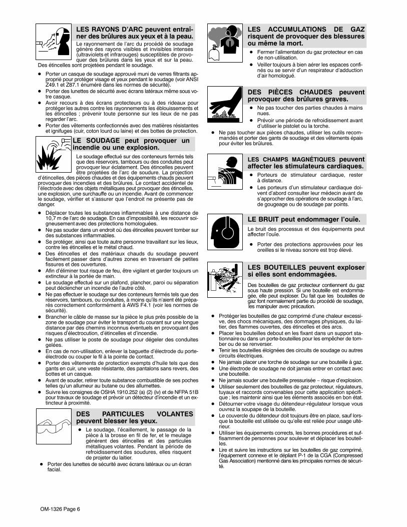
Le rayonnement de l’arc du procédé de soudagegénère des rayons visibles et invisibles intenses(ultraviolets et infrarouges) susceptibles de provo-quer des brûlures dans les yeux et sur la peau.
Des étincelles sont projetées pendant le soudage.
LES RAYONS D’ARC peuvent entraî-ner des brûlures aux yeux et à la peau.
� Porter un casque de soudage approuvé muni de verres filtrants ap-proprié pour protéger visage et yeux pendant le soudage (voir ANSIZ49.1 et Z87.1 énuméré dans les normes de sécurité).
� Porter des lunettes de sécurité avec écrans latéraux même sous vo-tre casque.
� Avoir recours à des écrans protecteurs ou à des rideaux pourprotéger les autres contre les rayonnements les éblouissements etles étincelles ; prévenir toute personne sur les lieux de ne pasregarder l’arc.
� Porter des vêtements confectionnés avec des matières résistanteset ignifuges (cuir, coton lourd ou laine) et des bottes de protection.
Le soudage effectué sur des conteneurs fermés telsque des réservoirs, tambours ou des conduites peutprovoquer leur éclatement. Des étincelles peuventêtre projetées de l’arc de soudure. La projection
d’étincelles, des pièces chaudes et des équipements chauds peuventprovoquer des incendies et des brûlures. Le contact accidentel del’électrode avec des objets métalliques peut provoquer des étincelles,une explosion, une surchauffe ou un incendie. Avant de commencerle soudage, vérifier et s’assurer que l’endroit ne présente pas dedanger.
LE SOUDAGE peut provoquer unincendie ou une explosion.
� Déplacer toutes les substances inflammables à une distance de10,7 m de l’arc de soudage. En cas d’impossibilité, les recouvrir soi-gneusement avec des protections homologuées.
� Ne pas souder dans un endroit où des étincelles peuvent tomber surdes substances inflammables.
� Se protéger, ainsi que toute autre personne travaillant sur les lieux,contre les étincelles et le métal chaud.
� Des étincelles et des matériaux chauds du soudage peuventfacilement passer dans d’autres zones en traversant de petitesfissures et des ouvertures.
� Afin d’éliminer tout risque de feu, être vigilant et garder toujours unextincteur à la portée de main.
� Le soudage effectué sur un plafond, plancher, paroi ou séparationpeut déclencher un incendie de l’autre côté.
� Ne pas effectuer le soudage sur des conteneurs fermés tels que desréservoirs, tambours, ou conduites, à moins qu’ils n’aient été prépa-rés correctement conformément à AWS F4.1 (voir les normes desécurité).
� Brancher le câble de masse sur la pièce le plus près possible de lazone de soudage pour éviter le transport du courant sur une longuedistance par des chemins inconnus éventuels en provoquant desrisques d’électrocution, d’étincelles et d’incendie.
� Ne pas utiliser le poste de soudage pour dégeler des conduitesgelées.
� En cas de non-utilisation, enlever la baguette d’électrode du porte-électrode ou couper le fil à la pointe de contact.
� Porter des vêtements de protection exempts d’huile tels que desgants en cuir, une veste résistante, des pantalons sans revers, desbottes et un casque.
� Avant de souder, retirer toute substance combustible de ses pochestelles qu’un allumeur au butane ou des allumettes.
� Suivre les consignes de OSHA 1910.252 (a) (2) (iv) et de NFPA 51Bpour travaux de soudage et prévoir un détecteur d’incendie et un ex-tincteur à proximité.
DES PARTICULES VOLANTESpeuvent blesser les yeux.� Le soudage, l’écaillement, le passage de la
pièce à la brosse en fil de fer, et le meulagegénèrent des étincelles et des particulesmétalliques volantes. Pendant la période derefroidissement des soudures, elles risquentde projeter du laitier.
� Porter des lunettes de sécurité avec écrans latéraux ou un écranfacial.
LES ACCUMULATIONS DE GAZrisquent de provoquer des blessuresou même la mort.� Fermer l’alimentation du gaz protecteur en cas
de non-utilisation.� Veiller toujours à bien aérer les espaces confi-
nés ou se servir d’un respirateur d’adductiond’air homologué.
DES PIÈCES CHAUDES peuventprovoquer des brûlures graves.� Ne pas toucher des parties chaudes à mains
nues.� Prévoir une période de refroidissement avant
d’utiliser le pistolet ou la torche.� Ne pas toucher aux pièces chaudes, utiliser les outils recom-
mandés et porter des gants de soudage et des vêtements épaispour éviter les brûlures.
LES CHAMPS MAGNÉTIQUES peuventaffecter les stimulateurs cardiaques.� Porteurs de stimulateur cardiaque, rester
à distance.� Les porteurs d’un stimulateur cardiaque doi-
vent d’abord consulter leur médecin avant des’approcher des opérations de soudage à l’arc,de gougeage ou de soudage par points.
LE BRUIT peut endommager l’ouïe.Le bruit des processus et des équipements peutaffecter l’ouïe.
� Porter des protections approuvées pour lesoreilles si le niveau sonore est trop élevé.
Des bouteilles de gaz protecteur contiennent du gazsous haute pression. Si une bouteille est endomma-gée, elle peut exploser. Du fait que les bouteilles degaz font normalement partie du procédé de soudage, les manipuler avec précaution.
� Protéger les bouteilles de gaz comprimé d’une chaleur excessi-ve, des chocs mécaniques, des dommages physiques, du lai-tier, des flammes ouvertes, des étincelles et des arcs.
� Placer les bouteilles debout en les fixant dans un support sta-tionnaire ou dans un porte-bouteilles pour les empêcher de tom-ber ou de se renverser.
� Tenir les bouteilles éloignées des circuits de soudage ou autrescircuits électriques.
� Ne jamais placer une torche de soudage sur une bouteille à gaz.� Une électrode de soudage ne doit jamais entrer en contact avec
une bouteille.� Ne jamais souder une bouteille pressurisée − risque d’explosion.� Utiliser seulement des bouteilles de gaz protecteur, régulateurs,
tuyaux et raccords convenables pour cette application spécifi-que ; les maintenir ainsi que les éléments associés en bon état.
� Détourner votre visage du détendeur-régulateur lorsque vousouvrez la soupape de la bouteille.
� Le couvercle du détendeur doit toujours être en place, sauf lors-que la bouteille est utilisée ou qu’elle est reliée pour usage ulté-rieur.
� Utiliser les équipements corrects, les bonnes procédures et suf-fisamment de personnes pour soulever et déplacer les bouteil-les.
� Lire et suivre les instructions sur les bouteilles de gaz comprimé,l’équipement connexe et le dépliant P-1 de la CGA (CompressedGas Association) mentionné dans les principales normes de sécuri-té.
LES BOUTEILLES peuvent explosersi elles sont endommagées.
OM-1326 Page 7
2-3. Dangers supplémentaires en relation avec l’installation, le fonctionnement et la maintenance
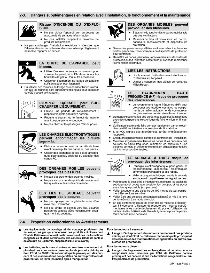
Risque D’INCENDIE OU D’EXPLO-SION.� Ne pas placer l’appareil sur, au-dessus ou
à proximité de surfaces inflammables.� Ne pas installer l’appareil à proximité de
produits inflammables.� Ne pas surcharger l’installation électrique − s’assurer que
l’alimentation est correctement dimensionnée et protégée avantde mettre l’appareil en service.
LA CHUTE DE L’APPAREIL peutblesser.� Utiliser l’anneau de levage uniquement pour
soulever l’appareil, NON PAS les chariots, lesbouteilles de gaz ou tout autre accessoire.
� Utiliser un équipement de levage de capacitésuffisante pour lever l’appareil.
� En utilisant des fourches de levage pour déplacer l’unité, s’assu-rer que les fourches sont suffisamment longues pour dépasserdu côté opposé de l’appareil.
L’EMPLOI EXCESSIF peut SUR-CHAUFFER L’ÉQUIPEMENT.� Prévoir une période de refroidissement ;
respecter le cycle opératoire nominal.� Réduire le courant ou le facteur de marche
avant de poursuivre le soudage.� Ne pas obstruer les passages d’air du poste.
LES CHARGES ÉLECTROSTATIQUESpeuvent endommager les circuitsimprimés.� Établir la connexion avec la barrette de terre
avant de manipuler des cartes ou des pièces.� Utiliser des pochettes et des boîtes antistati-
ques pour stocker, déplacer ou expédier descartes PC.
DES ORGANES MOBILES peuventprovoquer des blessures.� Ne pas s’approcher des organes mobiles.� Ne pas s’approcher des points de coincement
tels que des rouleaux de commande.
LES FILS DE SOUDAGE peuventprovoquer des blessures.� Ne pas appuyer sur la gâchette avant d’en
avoir reçu l’instruction.� Ne pas diriger le pistolet vers soi, d’autres
personnes ou toute pièce mécanique en enga-geant le fil de soudage.
DES ORGANES MOBILES peuventprovoquer des blessures.� S’abstenir de toucher des organes mobiles tels
que des ventilateurs.� Maintenir fermés et verrouillés les portes,
panneaux, recouvrements et dispositifs deprotection.
� Seules des personnes qualifiées sont autorisées à enlever lesportes, panneaux, recouvrements ou dispositifs de protectionpour l’entretien.
� Remettre les portes, panneaux, recouvrements ou dispositifs deprotection quand l’entretien est terminé et avant de rebrancherl’alimentation électrique.
LIRE LES INSTRUCTIONS.� Lire le manuel d’utilisation avant d’utiliser ou
d’intervenir sur l’appareil.� Utiliser uniquement des pièces de rechange
Miller/Hobart.
LE RAYONNEMENT HAUTEFRÉQUENCE (HF) risque de provoquerdes interférences.� Le rayonnement haute fréquence (HF) peut
provoquer des interférences avec les équipe-ments de radio-navigation et de communica-tion, les services de sécurité et les ordinateurs.
� Demander seulement à des personnes qualifiées familiariséesavec des équipements électroniques de faire fonctionner l’instal-lation.
� L’utilisateur est tenu de faire corriger rapidement par un électri-cien qualifié les interférences résultant de l’installation.
� Si le FCC signale des interférences, arrêter immédiatementl’appareil.
� Effectuer régulièrement le contrôle et l’entretien de l’installation.� Maintenir soigneusement fermés les portes et les panneaux des
sources de haute fréquence, maintenir les éclateurs à unedistance correcte et utiliser une terre et un blindage pour réduireles interférences éventuelles.
LE SOUDAGE À L’ARC risque deprovoquer des interférences.� L’énergie électromagnétique peut gêner le
fonctionnement d’appareils électroniquescomme des ordinateurs et des robots.
� Veiller à ce que tout l’équipement de la zone desoudage soit compatible électromagnétiquement.
� Pour réduire la possibilité d’interférence, maintenir les câbles desoudage aussi courts que possible, les grouper, et les poseraussi bas que possible (ex. par terre).
� Veiller à souder à une distance de 100 mètres de tout équipe-ment électronique sensible.
� Veiller à ce que ce poste de soudage soit posé et mis à la terreconformément à ce mode d’emploi.
� En cas d’interférences après avoir pris les mesures précéden-tes, il incombe à l’utilisateur de prendre des mesures supplé-mentaires telles que le déplacement du poste, l’utilisation decâbles blindés, l’utilisation de filtres de ligne ou la pose de protec-teurs dans la zone de travail.
2-4. Proposition californienne 65 Avertissements
� Les équipements de soudage et de coupage produisent desfumées et des gaz qui contiennent des produits chimiques dontl’État de Californie reconnaît qu’ils provoquent des malformationscongénitales et, dans certains cas, des cancers. (Code de santé etde sécurité de Californie, chapitre 25249.5 et suivants)
� Les batteries, les bornes et autres accessoires contiennent duplomb et des composés à base de plomb, produits chimiquesdont l’État de Californie reconnaît qu’ils provoquent des can-cers et des malformations congénitales ou autres problèmes deprocréation. Se laver les mains après manipulation.
Pour les moteurs à essence :� Les gaz d’échappement des moteurs contiennent des produits
chimiques dont l’État de Californie reconnaît qu’ils provoquentdes cancers et des malformations congénitales ou autres pro-blèmes de procréation.
Pour les moteurs diesel :� Les gaz d’échappement des moteurs diesel et certains de leurs
composants sont reconnus par l’État de Californie commeprovoquant des cancers et des malformations congénitales ou au-tres problèmes de procréation.

OM-1326 Page 8
2-5. Principales normes de sécurité
Safety in Welding, Cutting, and Allied Processes, ANSI Standard Z49.1,de Global Engineering Documents (téléphone : 1-877-413-5184, site In-ternet : www.global.ihs.com).
Recommended Safe Practices for the Preparation for Welding and Cut-ting of Containers and Piping, American Welding Society Standard AWSF4.1 de Global Engineering Documents (téléphone : 1-877-413-5184, siteInternet : www.global.ihs.com).
National Electrical Code, NFPA Standard 70, de National Fire ProtectionAssociation, P.O. Box 9101, 1 Battery March Park, Quincy, MA02269-9101 (téléphone : 617-770-3000, site Internet : www.nfpa.org).
Safe Handling of Compressed Gases in Cylinders, CGA Pamphlet P-1,de Compressed Gas Association, 1735 Jefferson Davis Highway, Suite1004, Arlington, VA 22202-4102 (téléphone : 703-412-0900, site Internet: www.cganet.com).
Code for Safety in Welding and Cutting, CSA Standard W117.2, deCanadian Standards Association, Standards Sales, 178 Rexdale
Boulevard, Rexdale, Ontario, Canada M9W 1R3 (téléphone :800-463-6727 ou à Toronto 416-747-4044, site Internet :www.csa-international.org).
Practice For Occupational And Educational Eye And Face Protection,ANSI Standard Z87.1, de American National Standards Institute, 11 West42nd Street, New York, NY 10036-8002 (téléphone : 212-642-4900, siteInternet : www.ansi.org).
Standard for Fire Prevention During Welding, Cutting, and Other HotWork, NFPA Standard 51B, de National Fire Protection Association, P.O.Box 9101, 1 Battery March Park, Quincy, MA 02269-9101 (téléphone :617-770-3000, site Internet : www.nfpa.org).
OSHA, Occupational Safety and Health Standards for General Industry,Title 29, Code of Federal Regulations (CFR), Part 1910, Subpart Q, andPart 1926, Subpart J, de U.S. Government Printing Office, Superinten-dent of Documents, P.O. Box 371954, Pittsburgh, PA 15250 (il y a 10bureaux régionaux−−le téléphone de la région 5, Chicago, est312-353-2220, site Internet : www.osha.gov).
2-6. Information EMF
Considérations sur le soudage et les effets de basse fréquence et deschamps magnétiques et électriques.
Le courant de soudage, pendant son passage dans les câbles de souda-ge, causera des champs électromagnétiques. Il y a eu et il y a encore uncertain souci à propos de tels champs. Cependant, après avoir examinéplus de 500 études qui ont été faites pendant une période de recherchede 17 ans, un comité spécial ruban bleu du National Research Council aconclu : « L’accumulation de preuves, suivant le jugement du comité, n’apas démontré que l’exposition aux champs magnétiques et champs élec-triques à haute fréquence représente un risque à la santé humaine ».Toutefois, des études sont toujours en cours et les preuves continuent àêtre examinées. En attendant que les conclusions finales de la recherchesoient établies, il vous serait souhaitable de réduire votre exposition auxchamps électromagnétiques pendant le soudage ou le coupage.
Pour réduire les champs magnétiques sur le poste de travail, appliquerles procédures suivantes :
1. Maintenir les câbles ensemble en les tordant ou en les enveloppant.
2. Disposer les câbles d’un côté et à distance de l’opérateur.
3. Ne pas courber pas et ne pas entourer pas les câbles autour devotre corps.
4. Garder le poste de soudage et les câbles le plus loin possible devous.
5. Connecter la pince sur la pièce aussi près que possible de la sou-dure.
En ce qui concerne les stimulateurs cardiaquesLes porteurs de stimulateur cardiaque doivent consulter leur médecinavant de souder ou d’approcher des opérations de soudage. Si le méde-cin approuve, il est recommandé de suivre les procédures précédentes.
OM-1326 Page 9
SECTION 3 − DEFINITIONS
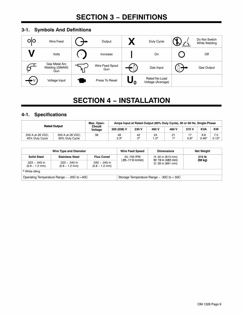
3-1. Symbols And Definitions
Wire Feed Output X Duty CycleDo Not SwitchWhile Welding
V Volts Increase On Off
Gas Metal ArcWelding (GMAW)
Gun
Wire Feed SpoolGun Gas Input Gas Output
Voltage Input Press To Reset U0Rated No-Load
Voltage (Average)
SECTION 4 − INSTALLATION
4-1. Specifications
Rated OutputMax. Open-
CircuitAmps Input at Rated Output (60% Duty Cycle), 50 or 60 Hz, Single-Phase
Rated Output CircuitVoltage 200 (208) V 230 V 400 V 460 V 575 V KVA KW
250 A at 28 VDC,40% Duty Cycle
200 A at 28 VDC,60% Duty Cycle
38 482.3*
422*
241.2*
211*
170.8*
9.80.46*
7.50.13*
Wire Type and Diameter Wire Feed Speed Dimensions Net Weight
Solid Steel Stainless Steel Flux Cored 25−700 IPM( 65 17 8 m/min)
H: 32 in (813 mm)W: 19 in (483 mm)
215 lb(98 kg)
.023 − .045 in(0.6 − 1.2 mm)
.023 − .045 in(0.6 − 1.2 mm)
.030 − .045 in(0.8 − 1.2 mm)
(.65−17.8 m/min) W: 19 in (483 mm)D: 39 in (991 mm)
(98 kg)
* While idling
Operating Temperature Range − −20C to +40C Storage Temperature Range − -30C to + 50C
OM-1326 Page 10
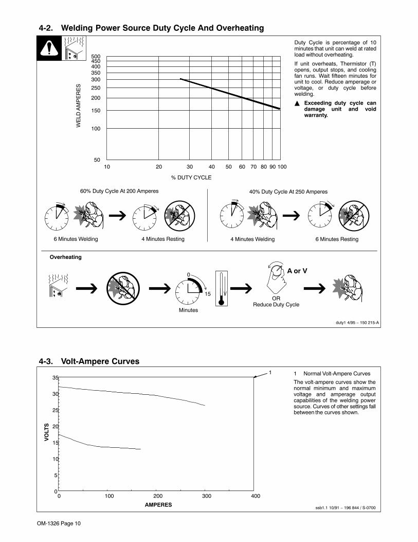
4-2. Welding Power Source Duty Cycle And Overheating
4 Minutes Welding 6 Minutes Resting6 Minutes Welding 4 Minutes Resting
Duty Cycle is percentage of 10minutes that unit can weld at ratedload without overheating.
If unit overheats, Thermistor (T)opens, output stops, and coolingfan runs. Wait fifteen minutes forunit to cool. Reduce amperage orvoltage, or duty cycle beforewelding.
� Exceeding duty cycle candamage unit and voidwarranty.
Overheating
0
15
A or V
ORReduce Duty Cycle
Minutes
duty1 4/95 − 150 215-A
40% Duty Cycle At 250 Amperes60% Duty Cycle At 200 Amperes
10 20 30 40 50 60 70 80 90 10050
100
150
200
250
300350400450500
% DUTY CYCLE
WE
LD A
MP
ER
ES
4-3. Volt-Ampere Curves
ssb1.1 10/91 − 196 844 / S-0700
1 Normal Volt-Ampere Curves
The volt-ampere curves show thenormal minimum and maximumvoltage and amperage outputcapabilities of the welding powersource. Curves of other settings fallbetween the curves shown.
1
0
5
10
15
20
25
30
35
0 100 200 300 400
AMPERES
VO
LTS
OM-1326 Page 11
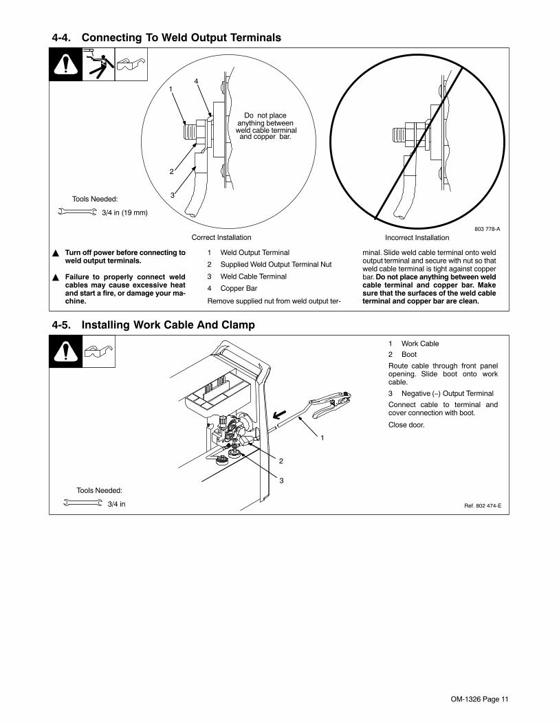
4-4. Connecting To Weld Output Terminals
803 778-A
� Turn off power before connecting toweld output terminals.
� Failure to properly connect weldcables may cause excessive heatand start a fire, or damage your ma-chine.
1 Weld Output Terminal
2 Supplied Weld Output Terminal Nut
3 Weld Cable Terminal
4 Copper Bar
Remove supplied nut from weld output ter-
minal. Slide weld cable terminal onto weldoutput terminal and secure with nut so thatweld cable terminal is tight against copperbar. Do not place anything between weldcable terminal and copper bar. Makesure that the surfaces of the weld cableterminal and copper bar are clean.
Tools Needed:
3/4 in (19 mm)
4
2
3
Do not placeanything between
Correct Installation Incorrect Installation
1
weld cable terminaland copper bar.
4-5. Installing Work Cable And Clamp
Ref. 802 474-E
Tools Needed:
3/4 in
3
2
1
1 Work Cable
2 Boot
Route cable through front panelopening. Slide boot onto workcable.
3 Negative (−) Output Terminal
Connect cable to terminal andcover connection with boot.
Close door.
OM-1326 Page 12
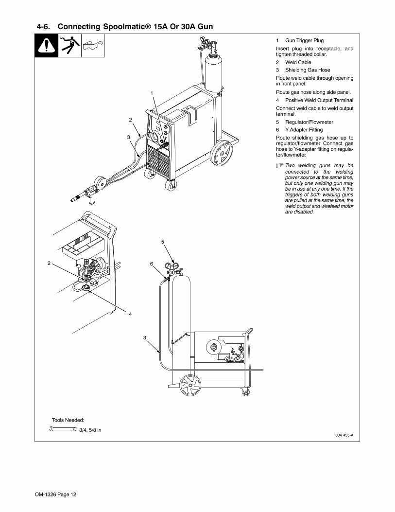
4-6. Connecting Spoolmatic� 15A Or 30A Gun
804 455-A
1 Gun Trigger Plug
Insert plug into receptacle, andtighten threaded collar.
2 Weld Cable
3 Shielding Gas Hose
Route weld cable through openingin front panel.
Route gas hose along side panel.
4 Positive Weld Output Terminal
Connect weld cable to weld outputterminal.
5 Regulator/Flowmeter
6 Y-Adapter Fitting
Route shielding gas hose up toregulator/flowmeter. Connect gashose to Y-adapter fitting on regula-tor/flowmeter.
� Two welding guns may beconnected to the weldingpower source at the same time,but only one welding gun maybe in use at any one time. If thetriggers of both welding gunsare pulled at the same time, theweld output and wirefeed motorare disabled.
Tools Needed:
3/4, 5/8 in
1
2
3
4
2
5
6
3
OM-1326 Page 13
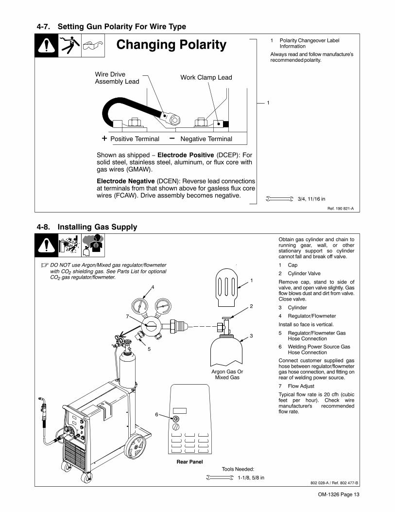
4-7. Setting Gun Polarity For Wire Type
1 Polarity Changeover LabelInformation
Always read and follow manufacture’srecommended polarity.
1
3/4, 11/16 in
Ref. 190 821-A
Changing Polarity
�
�
Wire DriveAssembly Lead
Work Clamp Lead
� Positive Terminal
Shown as shipped − Electrode Positive (DCEP): Forsolid steel, stainless steel, aluminum, or flux core withgas wires (GMAW).
� Negative Terminal
Electrode Negative (DCEN): Reverse lead connectionsat terminals from that shown above for gasless flux corewires (FCAW). Drive assembly becomes negative.
4-8. Installing Gas Supply
802 028-A / Ref. 802 477-B
Tools Needed:
Obtain gas cylinder and chain torunning gear, wall, or otherstationary support so cylindercannot fall and break off valve.
1 Cap
2 Cylinder Valve
Remove cap, stand to side ofvalve, and open valve slightly. Gasflow blows dust and dirt from valve.Close valve.
3 Cylinder
4 Regulator/Flowmeter
Install so face is vertical.
5 Regulator/Flowmeter GasHose Connection
6 Welding Power Source GasHose Connection
Connect customer supplied gashose between regulator/flowmetergas hose connection, and fitting onrear of welding power source.
7 Flow Adjust
Typical flow rate is 20 cfh (cubicfeet per hour). Check wiremanufacturer’s recommendedflow rate.
1-1/8, 5/8 in
1
2
3
Argon Gas OrMixed Gas
4
5
7
� DO NOT use Argon/Mixed gas regulator/flowmeterwith CO2 shielding gas. See Parts List for optionalCO2 gas regulator/flowmeter.
Rear Panel
6
OM-1326 Page 14
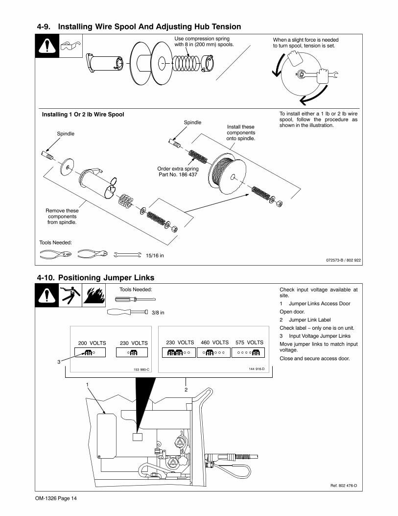
4-9. Installing Wire Spool And Adjusting Hub Tension
When a slight force is neededto turn spool, tension is set.
15/16 in
Use compression springwith 8 in (200 mm) spools.
Tools Needed:
072573-B / 802 922
Installing 1 Or 2 lb Wire Spool To install either a 1 lb or 2 lb wirespool, follow the procedure asshown in the illustration.
Remove thesecomponentsfrom spindle.
Spindle
SpindleInstall thesecomponentsonto spindle.
Order extra springPart No. 186 437
4-10. Positioning Jumper Links
Ref. 802 476-D
Check input voltage available atsite.
1 Jumper Links Access Door
Open door.
2 Jumper Link Label
Check label − only one is on unit.
3 Input Voltage Jumper Links
Move jumper links to match inputvoltage.
Close and secure access door.3
Tools Needed:
21
3/8 in
200�VOLTS 230�VOLTS
153 980-C
230�VOLTS 460�VOLTS 575�VOLTS
144 916-D

OM-1326 Page 15
4-11. Electrical Service Guide
Input Voltage 200 230 400 460 575
Input Amperes At Rated Output 48 42 24 21 17
Max Recommended Standard Fuse Or Circuit Breaker Rating In Amperes
Circuit Breaker 1, Time-Delay 2 60 50 30 25 20
Normal Operating 3 70 60 35 30 25
Min Input Conductor Size In AWG4 8 8 12 12 14
Max Recommended Input Conductor Length In Feet (Meters)96
(29)127(39)
156(47)
206(63)
209(64)
Min Grounding Conductor Size In AWG4 8 10 12 12 14
Reference: 2005 National Electrical Code (NEC) (including article 630)
1 Choose a circuit breaker with time-current curves comparable to a Time Delay Fuse.2 “Time-Delay” fuses are UL class “RK5” .3 “Normal Operating” (general purpose − no intentional delay) fuses are UL class “K5” (up to and including 60 amp), and UL class “H” ( 65 amp and
above).4 Conductor data in this section specifies conductor size (excluding flexible cord or cable) between the panelboard and the equipment per NEC Table
310.16. If a flexible cord or cable is used, minimum conductor size may increase. See NEC Table 400.5(A) for flexible cord and cable requirements.� Caution: Failure to follow these fuse and circuit breaker recommendations could create an electric shock or fire hazard. These
recommendations are for a dedicated branch circuit that applies to the rated output and duty cycle of the welding power source.
OM-1326 Page 16
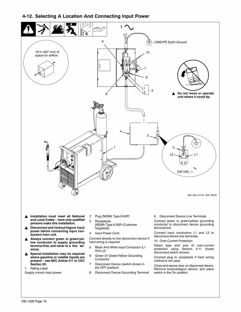
4-12. Selecting A Location And Connecting Input Power
Ref. 802 477-B / 803 766-B
L1L2
230 VAC, 1
18 in (457 mm) ofspace for airflow
� Do not move or operateunit where it could tip.
3
2
1
4
� Installation must meet all Nationaland Local Codes − have only qualifiedpersons make this installation.
� Disconnect and lockout/tagout inputpower before connecting input con-ductors from unit.
� Always connect green or green/yel-low conductor to supply groundingterminal first, and never to a line ter-minal.
� Special installation may be requiredwhere gasoline or volatile liquids arepresent − see NEC Article 511 or CECSection 20.
1 Rating LabelSupply correct input power.
2 Plug (NEMA Type 6-50P)
3 Receptacle[NEMA Type 6-50R (CustomerSupplied)]
4 Input Power Cord.
Connect directly to line disconnect device ifhard wiring is required.
5 Black And White Input Conductor (L1And L2)
6 Green Or Green/Yellow GroundingConductor
7 Disconnect Device (switch shown inthe OFF position)
8 Disconnect Device Grounding Terminal
9 Disconnect Device Line Terminals
Connect green or green/yellow groundingconductor to disconnect device groundingterminal first.
Connect input conductors L1 and L2 todisconnect device line terminals.
10 Over-Current ProtectionSelect type and size of over-currentprotection using Section 4-11 (fuseddisconnect switch shown).
Connect plug to receptacle if hard wiringmethod is not used.
Close and secure door on disconnect device.Remove lockout/tagout device, and placeswitch in the On position.
7
L1L2
1
=GND/PE Earth Ground
65
8
9
10
OM-1326 Page 17
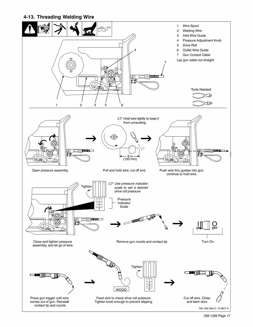
4-13. Threading Welding Wire
1 Wire Spool
2 Welding Wire
3 Inlet Wire Guide
4 Pressure Adjustment Knob
5 Drive Roll
6 Outlet Wire Guide7 Gun Conduit Cable
Lay gun cable out straight.
4
7
3 5 621
Tools Needed:
6 in(150 mm)
� Hold wire tightly to keep itfrom unraveling.
WOOD
Open pressure assembly. Pull and hold wire; cut off end. Push wire thru guides into gun;continue to hold wire.
Close and tighten pressure assembly, and let go of wire.
Remove gun nozzle and contact tip. Turn On.
Press gun trigger until wire comes out of gun. Reinstall
contact tip and nozzle
Feed wire to check drive roll pressure.Tighten knob enough to prevent slipping.
Cut off wire. Close and latch door.
Ref. 802 064-D / S-0627-A
Tighten
1234
� Use pressure indicatorscale to set a desireddrive roll pressure.
PressureIndicator
Scale
Tighten
1234
OM-1326 Page 18
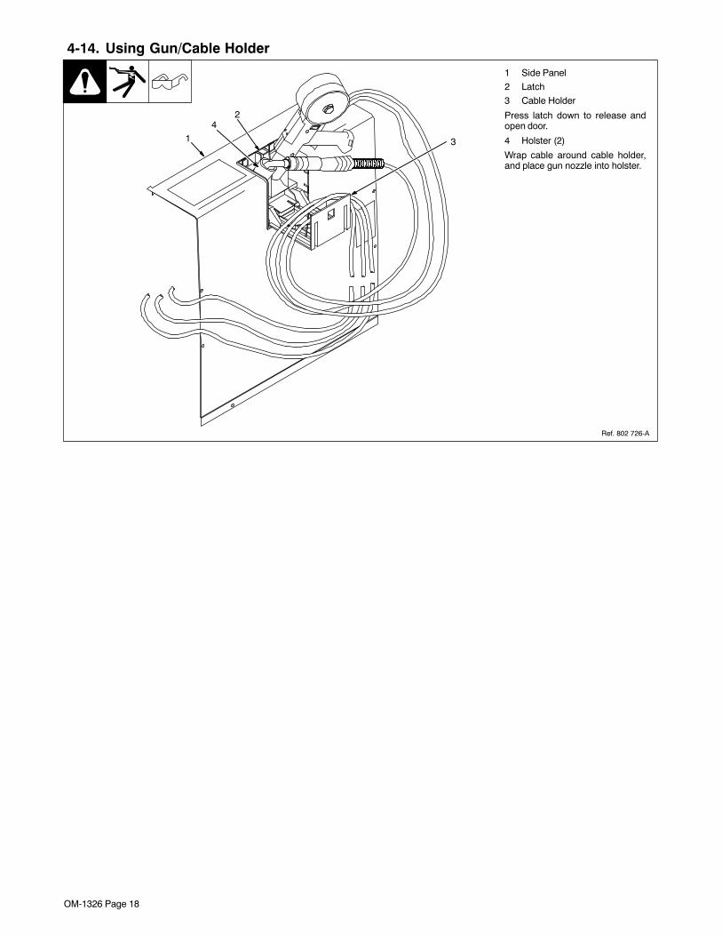
Ref. 802 726-A
1 Side Panel
2 Latch
3 Cable Holder
Press latch down to release andopen door.
4 Holster (2)
Wrap cable around cable holder,and place gun nozzle into holster.
1
2
4-14. Using Gun/Cable Holder
3
4

OM-1326 Page 19
Notes
OM-1326 Page 20
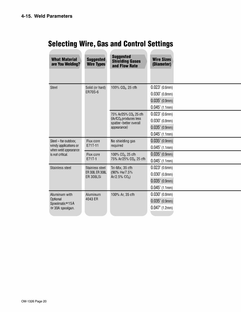
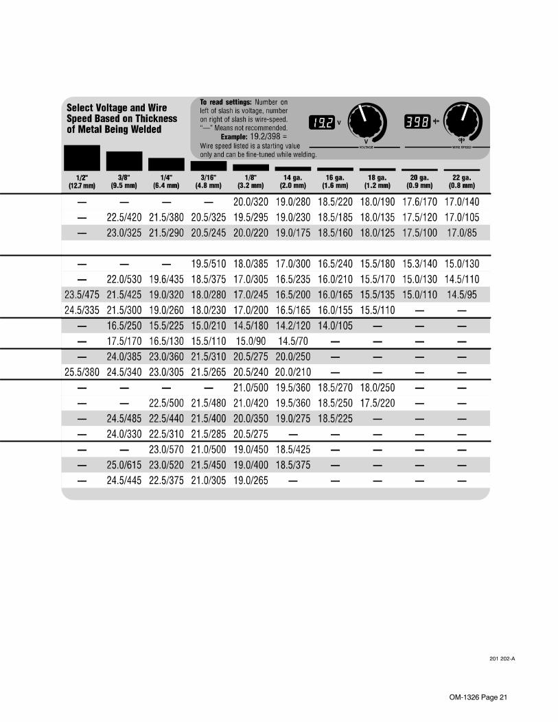
4-15. Weld Parameters
OM-1326 Page 21
201 202-A

OM-1326 Page 22
SECTION 5 − OPERATION
5-1. Controls
Ref. 205 637
1 Voltage Control
Turn control clockwise to increasevoltage.
2 Wire Speed Control
Turn control clockwise to increase wirefeed speed.
JOG Mode
If the trigger on either gun is held formore than 3 seconds without strikingan arc, the unit will automatically shutoff weld power (and shielding gasoutput on MIG gun only), but will feedwire continuously at the preset wirefeed speed (which may be faster orslower than Run−in Speed) until triggeris released.
Run−in Wire Feed Speed Settings
Run−in settings for the MIG and SpoolGuns are independently set and storedin unit memory. The settings are inpercent of the welding wire feed speedpreset. Both settings are adjustablefrom 25 to 150 percent.
MIG Gun Run−in is factory set at 100%which is recommended for most wiresizes and types.
Spool Gun Run−in is factory set at 50%which is recommended for .030 & .035wire. A Run−in setting of 25% isrecommended for .047 wire.
To check Run−in settings, start withthe power switch OFF. Press and holdthe MIG or Spool Gun Trigger whileturning the power switch ON. The unitwill power up with both the displaysreading 888 , then the voltage displaywill read −−− and the wire feed displaywill read the preset Run−in percentagefrom memory for the gun selected. Toreturn to the weld mode withoutmaking a change, simply releasetrigger and pull the trigger againmomentarily (one second).
To change Run−in settings, start withthe power switch OFF. Press and holdthe MIG or Spool Gun Trigger whileturning the power switch ON. The unitwill power up with both the displaysreading 888 , then the voltage displaywill read −−− and the wire feed displaywill read the preset Run−in percentagefrom memory for the gun selected. Tochange the Run−in value, release thetrigger and turn the wire feed controlknob (or the wire feed adjustment knoblocated on the bottom handle of thespool gun) to the desired setting for theselected gun. To return to weld modeafter the Run−in speed change, pullthe trigger momentarily (one second).
3 Power Switch
4 Voltmeter
5 Wire Feed Speed Meter
1
2
3
4
5
� This unit has three automatic timers included in its operation tohelp save contact tips, gas, and wire:
Tip Saver − Weld output shuts off if tip is shorted to work surface.
Safety shut-off − Weld output will shut off if no arc is detected within 3seconds after gun trigger is depressed.
Jog mode − When loading a new roll of wire or if the gun trigger isaccidentally pressed, gas will shut off after 1 minute and wire will shut offafter 2 minutes saving wire and gas.
OM-1326 Page 23
5-2. Voltmeter And Wire Feed Speed Meter Operation
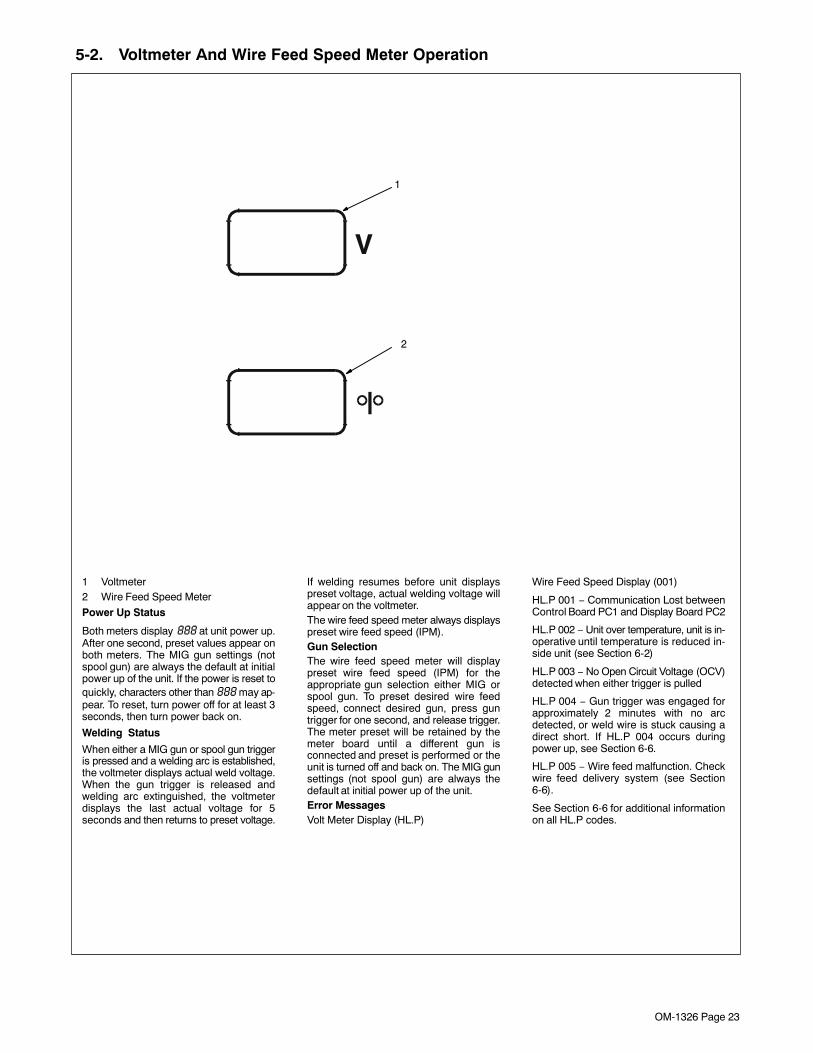
1 Voltmeter2 Wire Feed Speed Meter
Power Up Status
Both meters display 888 at unit power up.After one second, preset values appear onboth meters. The MIG gun settings (notspool gun) are always the default at initialpower up of the unit. If the power is reset toquickly, characters other than 888 may ap-pear. To reset, turn power off for at least 3seconds, then turn power back on.
Welding Status
When either a MIG gun or spool gun triggeris pressed and a welding arc is established,the voltmeter displays actual weld voltage.When the gun trigger is released andwelding arc extinguished, the voltmeterdisplays the last actual voltage for 5seconds and then returns to preset voltage.
If welding resumes before unit displayspreset voltage, actual welding voltage willappear on the voltmeter.The wire feed speed meter always displayspreset wire feed speed (IPM).Gun SelectionThe wire feed speed meter will displaypreset wire feed speed (IPM) for theappropriate gun selection either MIG orspool gun. To preset desired wire feedspeed, connect desired gun, press guntrigger for one second, and release trigger.The meter preset will be retained by themeter board until a different gun isconnected and preset is performed or theunit is turned off and back on. The MIG gunsettings (not spool gun) are always thedefault at initial power up of the unit.Error MessagesVolt Meter Display (HL.P)
Wire Feed Speed Display (001)
HL.P 001 − Communication Lost betweenControl Board PC1 and Display Board PC2
HL.P 002 − Unit over temperature, unit is in-operative until temperature is reduced in-side unit (see Section 6-2)
HL.P 003 − No Open Circuit Voltage (OCV)detected when either trigger is pulled
HL.P 004 − Gun trigger was engaged forapproximately 2 minutes with no arcdetected, or weld wire is stuck causing adirect short. If HL.P 004 occurs duringpower up, see Section 6-6.
HL.P 005 − Wire feed malfunction. Checkwire feed delivery system (see Section6-6).
See Section 6-6 for additional informationon all HL.P codes.
1
2
OM-1326 Page 24
SECTION 6 − MAINTENANCE &TROUBLESHOOTING
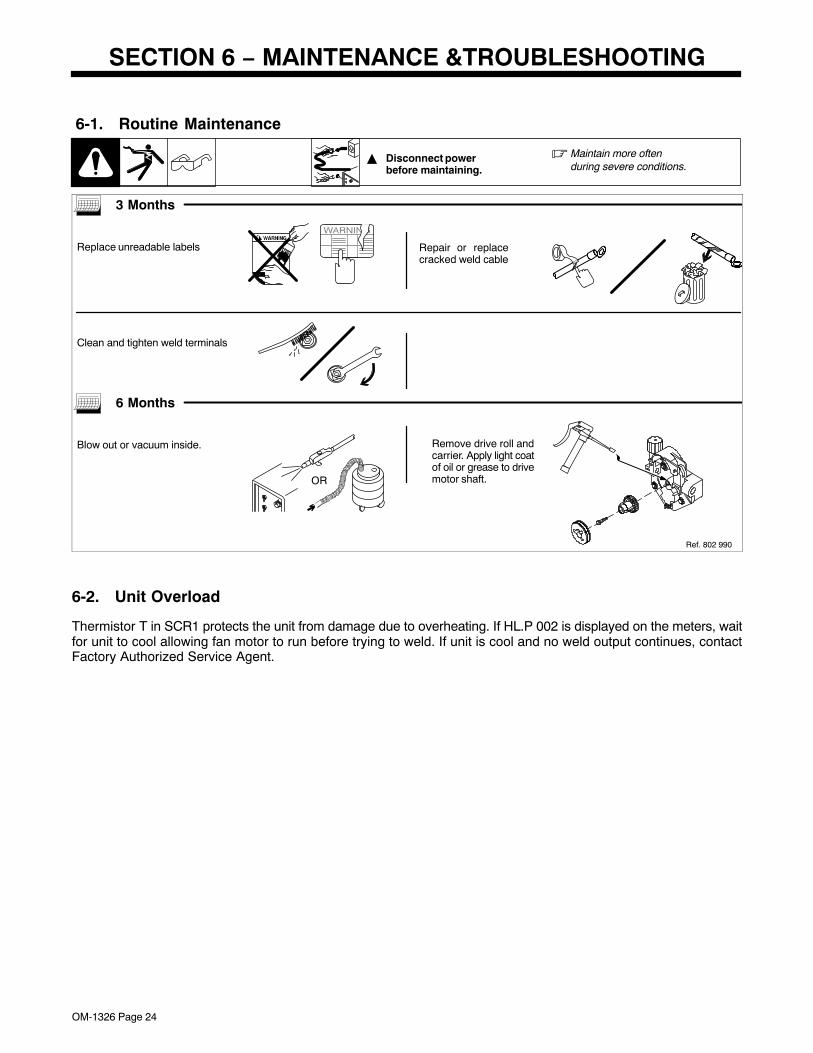
6-1. Routine Maintenance
� Disconnect power before maintaining.
� Maintain more oftenduring severe conditions.
3 Months
Replace unreadable labels Repair or replacecracked weld cable
Clean and tighten weld terminals
6 Months
Blow out or vacuum inside.
OR
Remove drive roll andcarrier. Apply light coatof oil or grease to drivemotor shaft.
Ref. 802 990
6-2. Unit Overload
Thermistor T in SCR1 protects the unit from damage due to overheating. If HL.P 002 is displayed on the meters, waitfor unit to cool allowing fan motor to run before trying to weld. If unit is cool and no weld output continues, contactFactory Authorized Service Agent.
OM-1326 Page 25
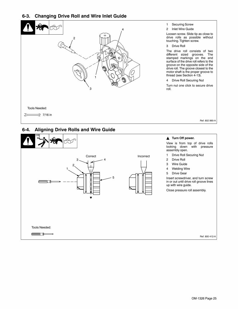
6-3. Changing Drive Roll and Wire Inlet Guide
1 Securing Screw
2 Inlet Wire Guide
Loosen screw. Slide tip as close todrive rolls as possible withouttouching. Tighten screw.
3 Drive Roll
The drive roll consists of twodifferent sized grooves. Thestamped markings on the endsurface of the drive roll refers to thegroove on the opposite side of thedrive roll. The groove closest to themotor shaft is the proper groove tothread (see Section 4-13).
4 Drive Roll Securing Nut
Turn nut one click to secure driveroll.
Tools Needed:
7/16 in
Ref. 802 990-A
1
2
3
4
6-4. Aligning Drive Rolls and Wire Guide
� Turn Off power.
View is from top of drive rollslooking down with pressureassembly open.
1 Drive Roll Securing Nut
2 Drive Roll3 Wire Guide
4 Welding Wire
5 Drive Gear
Insert screwdriver, and turn screwin or out until drive roll groove linesup with wire guide.
Close pressure roll assembly.
Ref. 800 412-A
Correct Incorrect43
21
5
Tools Needed:
OM-1326 Page 26
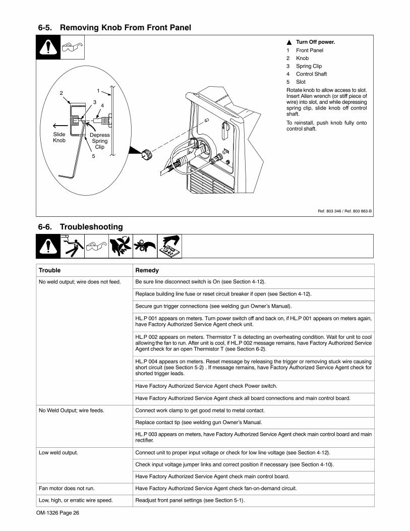
6-5. Removing Knob From Front Panel
� Turn Off power.
1 Front Panel
2 Knob
3 Spring Clip
4 Control Shaft
5 Slot
Rotate knob to allow access to slot.Insert Allen wrench (or stiff piece ofwire) into slot, and while depressingspring clip, slide knob off controlshaft.
To reinstall, push knob fully ontocontrol shaft.
Ref. 803 346 / Ref. 803 863-B
12
43
5
DepressSpring
Clip
SlideKnob
6-6. Troubleshooting
Trouble Remedy
No weld output; wire does not feed. Be sure line disconnect switch is On (see Section 4-12).
Replace building line fuse or reset circuit breaker if open (see Section 4-12).
Secure gun trigger connections (see welding gun Owner’s Manual).
HL.P 001 appears on meters. Turn power switch off and back on, if HL.P 001 appears on meters again,have Factory Authorized Service Agent check unit.
HL.P 002 appears on meters. Thermistor T is detecting an overheating condition. Wait for unit to coolallowing the fan to run. After unit is cool, if HL.P 002 message remains, have Factory Authorized ServiceAgent check for an open Thermistor T (see Section 6-2).
HL.P 004 appears on meters. Reset message by releasing the trigger or removing stuck wire causingshort circuit (see Section 5-2) . If message remains, have Factory Authorized Service Agent check forshorted trigger leads.
Have Factory Authorized Service Agent check Power switch.
Have Factory Authorized Service Agent check all board connections and main control board.
No Weld Output; wire feeds. Connect work clamp to get good metal to metal contact.
Replace contact tip (see welding gun Owner’s Manual.
HL.P 003 appears on meters, have Factory Authorized Service Agent check main control board and mainrectifier.
Low weld output. Connect unit to proper input voltage or check for low line voltage (see Section 4-12).
Check input voltage jumper links and correct position if necessary (see Section 4-10).
Have Factory Authorized Service Agent check main control board.
Fan motor does not run. Have Factory Authorized Service Agent check fan-on-demand circuit.
Low, high, or erratic wire speed. Readjust front panel settings (see Section 5-1).

OM-1326 Page 27
Trouble Remedy
Change to correct size drive rolls (see Section 6-3).
Readjust drive roll pressure (see Section 4-13).
Replace inlet guide, contact tip, and/or liner if necessary (see welding gun Owner’s Manual).
Check position of input jumper links (see Section 4-10).
Have Factory Authorized Service Agent check main control board.
No wire feed. Turn Wire Speed control to higher setting (see Section 5-1).
Clear obstruction in gun contact tip or liner (see welding gun Owner’s Manual).
Readjust drive roll pressure (see Section 4-13).
Change to correct size drive rolls (see Section 6-3).
Rethread welding wire (see Section 4-13).
HL.P 002 appears on meters. Thermistor T is detecting an overheating condition. Wait for unit to coolallowing the fan to run. After unit is cool, If HL.P 002 message remains, contact Factory AuthorizedService Agent (see Section 6-2).
HL.P 004 appears on meters. Reset message by releasing the trigger or removing stuck wire causingshort circuit (see Section 5-2) . If message remains, have Factory Authorized Service Agent check forshorted trigger leads.
HL.P 005 appears on meters. Wire feed malfunction. Check wire feed delivery system.
Check gun trigger and leads. Repair or replace gun if necessary.
Have Factory Authorized Service Agent check main control board.
OM-1326 Page 28
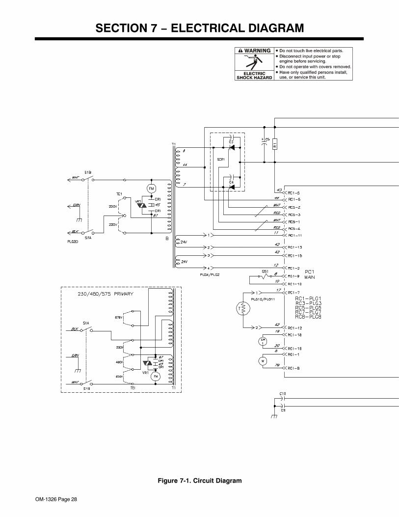
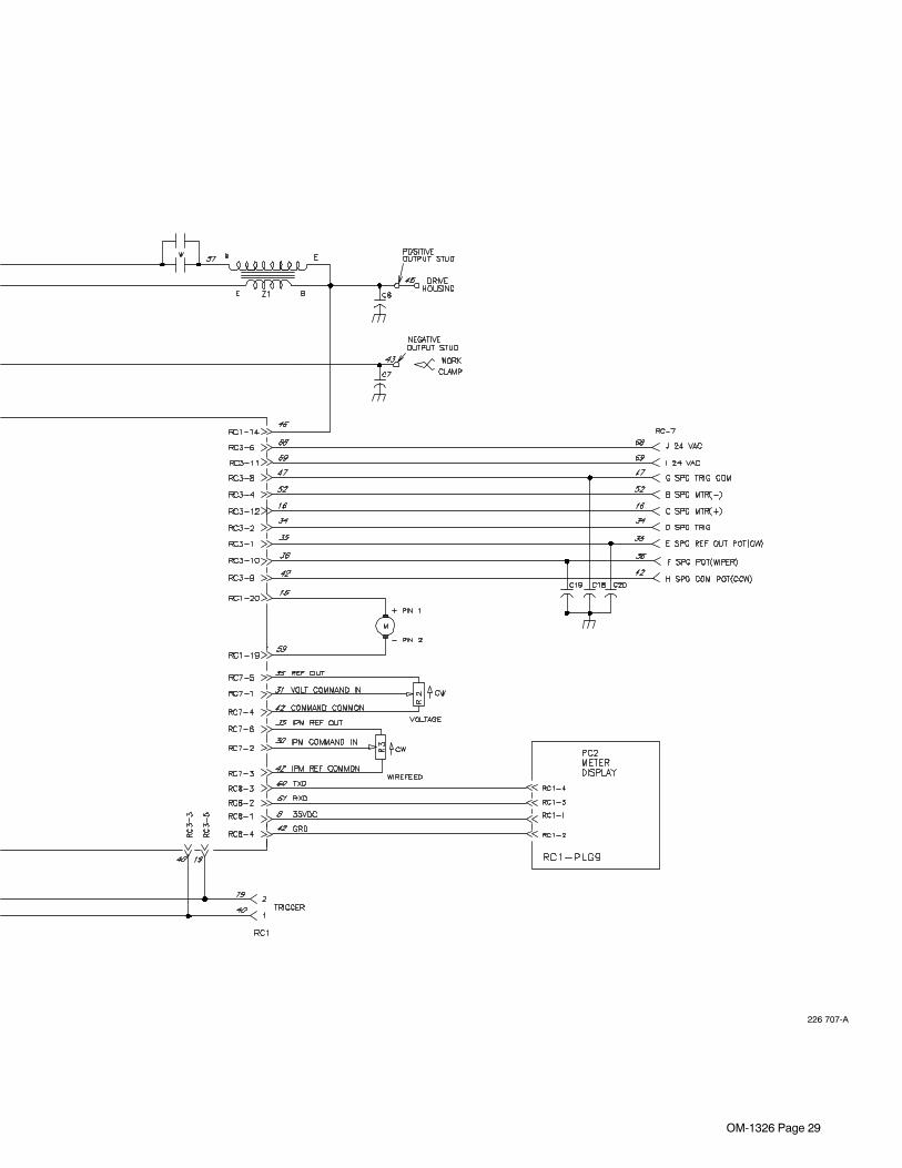
SECTION 7 − ELECTRICAL DIAGRAM
Figure 7-1. Circuit Diagram
OM-1326 Page 29
226 707-A
OM-1326 Page 30
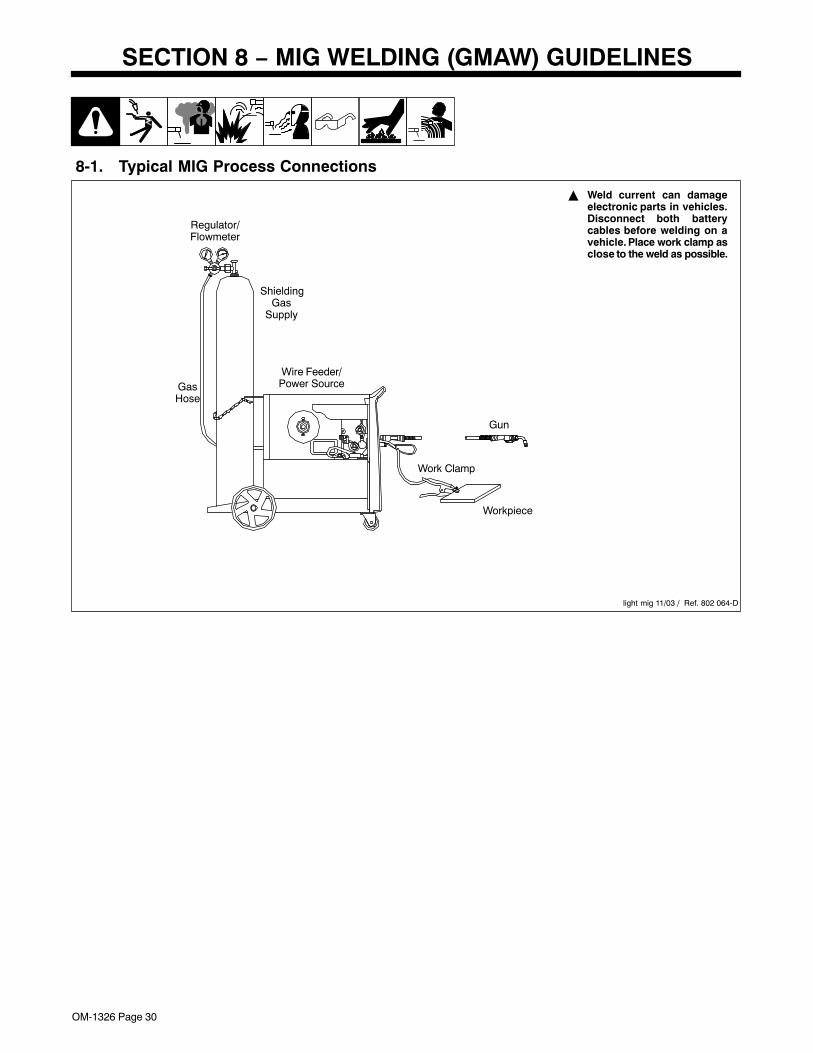
SECTION 8 − MIG WELDING (GMAW) GUIDELINES
8-1. Typical MIG Process Connections
� Weld current can damageelectronic parts in vehicles.Disconnect both batterycables before welding on avehicle. Place work clamp asclose to the weld as possible.
light mig 11/03 / Ref. 802 064-D
Wire Feeder/Power Source
Workpiece
Gun
Regulator/Flowmeter
GasHose
ShieldingGas
Supply
Work Clamp
OM-1326 Page 31
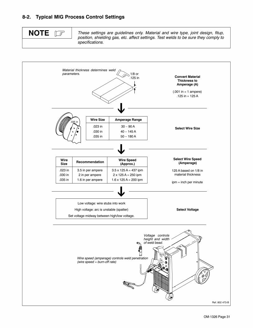
8-2. Typical MIG Process Control Settings
These settings are guidelines only. Material and wire type, joint design, fitup,position, shielding gas, etc. affect settings. Test welds to be sure they comply tospecifications.
NOTE
1/8 or.125 in
Material thickness determines weldparameters.
Convert Material
(.001 in = 1 ampere).125 in = 125 A
Select Wire Size
Wire Size Amperage Range
.030 in
.035 in
.023 in
40 − 145 A
50 − 180 A
30 − 90 A
.035 in
Select Wire Speed
Select Voltage
Wire Recommendation
.030 in
.035 in
.023 in2 in per ampere
1.6 in per ampere
3.5 in per ampere
Wire Speed
2 x 125 A = 250 ipm
1.6 x 125 A = 200 ipm
3.5 x 125 A = 437 ipm
Set voltage midway between high/low voltage.
Low voltage: wire stubs into work
High voltage: arc is unstable (spatter)
125 A based on 1/8 in
Thickness to
(Amperage)
material thickness
Size (Approx.)
Amperage (A)
ipm = inch per minute
Ref. 802 473-B
Voltage controlsheight and widthof weld bead.
Wire speed (amperage) controls weld penetration(wire speed = burn-off rate)
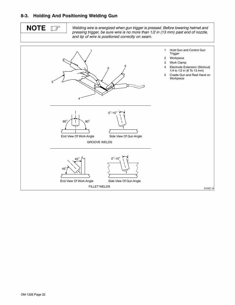
OM-1326 Page 32
8-3. Holding And Positioning Welding Gun
Welding wire is energized when gun trigger is pressed. Before lowering helmet andpressing trigger, be sure wire is no more than 1/2 in (13 mm) past end of nozzle,and tip of wire is positioned correctly on seam.
NOTE
1 Hold Gun and Control GunTrigger
2 Workpiece
3 Work Clamp
4 Electrode Extension (Stickout)1/4 to 1/2 in (6 To 13 mm)
5 Cradle Gun and Rest Hand onWorkpiece
23
5
4
90° 90°
0°-15°
45°
45°
GROOVE WELDS
FILLET WELDS
End View Of Work Angle Side View Of Gun Angle
End View Of Work Angle Side View Of Gun Angle
1
0°-15°
S-0421-A
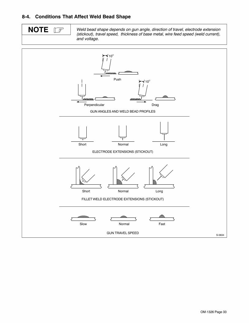
OM-1326 Page 33
8-4. Conditions That Affect Weld Bead Shape
Weld bead shape depends on gun angle, direction of travel, electrode extension(stickout), travel speed, thickness of base metal, wire feed speed (weld current),and voltage.
NOTE
Short Normal Long
Short Normal Long
10°
10°
GUN ANGLES AND WELD BEAD PROFILES
ELECTRODE EXTENSIONS (STICKOUT)
FILLET WELD ELECTRODE EXTENSIONS (STICKOUT)
Push
Perpendicular Drag
GUN TRAVEL SPEED
Slow Normal Fast
S-0634
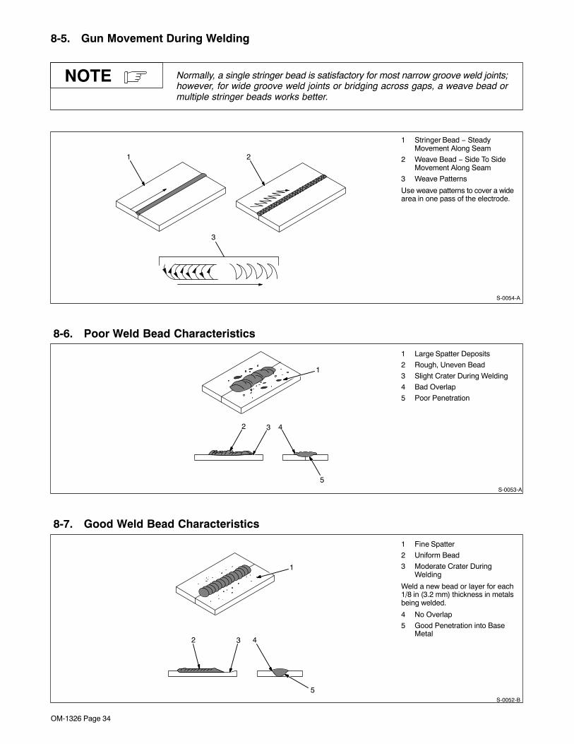
OM-1326 Page 34
8-5. Gun Movement During Welding
Normally, a single stringer bead is satisfactory for most narrow groove weld joints;however, for wide groove weld joints or bridging across gaps, a weave bead ormultiple stringer beads works better.
NOTE
1 Stringer Bead − SteadyMovement Along Seam
2 Weave Bead − Side To SideMovement Along Seam
3 Weave Patterns
Use weave patterns to cover a widearea in one pass of the electrode.
S-0054-A
3
1 2
8-6. Poor Weld Bead Characteristics
1 Large Spatter Deposits
2 Rough, Uneven Bead
3 Slight Crater During Welding
4 Bad Overlap
5 Poor Penetration
5
42 3
1
S-0053-A
8-7. Good Weld Bead Characteristics
1 Fine Spatter
2 Uniform Bead
3 Moderate Crater DuringWelding
Weld a new bead or layer for each1/8 in (3.2 mm) thickness in metalsbeing welded.
4 No Overlap
5 Good Penetration into BaseMetal
S-0052-B
2 3
1
4
5
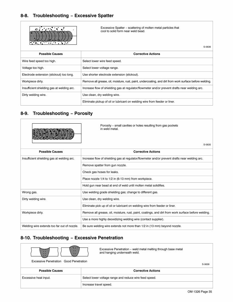
OM-1326 Page 35
8-8. Troubleshooting − Excessive Spatter
Excessive Spatter − scattering of molten metal particles thatcool to solid form near weld bead.
S-0636
Possible Causes Corrective Actions
Wire feed speed too high. Select lower wire feed speed.
Voltage too high. Select lower voltage range.
Electrode extension (stickout) too long. Use shorter electrode extension (stickout).
Workpiece dirty. Remove all grease, oil, moisture, rust, paint, undercoating, and dirt from work surface before welding.
Insufficient shielding gas at welding arc. Increase flow of shielding gas at regulator/flowmeter and/or prevent drafts near welding arc.
Dirty welding wire. Use clean, dry welding wire.
Eliminate pickup of oil or lubricant on welding wire from feeder or liner.
8-9. Troubleshooting − Porosity
Porosity − small cavities or holes resulting from gas pocketsin weld metal.
S-0635
Possible Causes Corrective Actions
Insufficient shielding gas at welding arc. Increase flow of shielding gas at regulator/flowmeter and/or prevent drafts near welding arc.
Remove spatter from gun nozzle.
Check gas hoses for leaks.
Place nozzle 1/4 to 1/2 in (6-13 mm) from workpiece.
Hold gun near bead at end of weld until molten metal solidifies.
Wrong gas. Use welding grade shielding gas; change to different gas.
Dirty welding wire. Use clean, dry welding wire.
Eliminate pick up of oil or lubricant on welding wire from feeder or liner.
Workpiece dirty. Remove all grease, oil, moisture, rust, paint, coatings, and dirt from work surface before welding.
Use a more highly deoxidizing welding wire (contact supplier).
Welding wire extends too far out of nozzle. Be sure welding wire extends not more than 1/2 in (13 mm) beyond nozzle.
8-10. Troubleshooting − Excessive Penetration
Good Penetration
Excessive Penetration − weld metal melting through base metaland hanging underneath weld.
Excessive PenetrationS-0639
Possible Causes Corrective Actions
Excessive heat input. Select lower voltage range and reduce wire feed speed.
Increase travel speed.
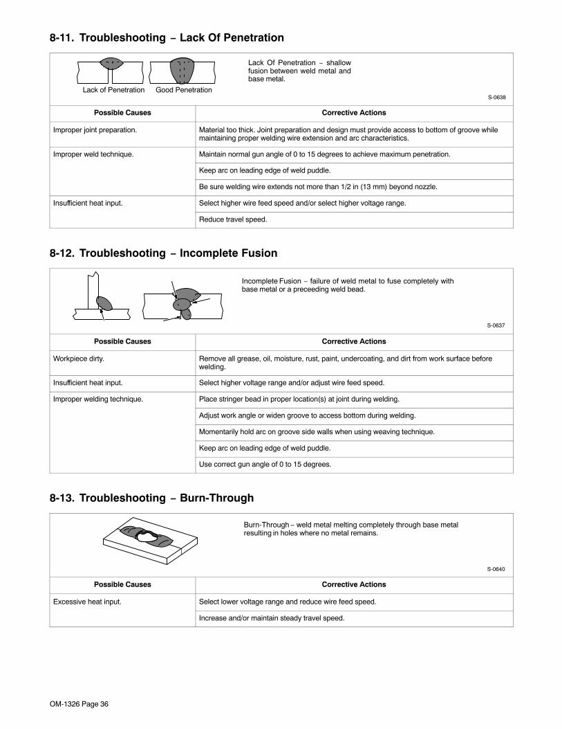
OM-1326 Page 36
8-11. Troubleshooting − Lack Of Penetration
Lack Of Penetration − shallowfusion between weld metal andbase metal.
Lack of Penetration Good PenetrationS-0638
Possible Causes Corrective Actions
Improper joint preparation. Material too thick. Joint preparation and design must provide access to bottom of groove whilemaintaining proper welding wire extension and arc characteristics.
Improper weld technique. Maintain normal gun angle of 0 to 15 degrees to achieve maximum penetration.
Keep arc on leading edge of weld puddle.
Be sure welding wire extends not more than 1/2 in (13 mm) beyond nozzle.
Insufficient heat input. Select higher wire feed speed and/or select higher voltage range.
Reduce travel speed.
8-12. Troubleshooting − Incomplete Fusion
Incomplete Fusion − failure of weld metal to fuse completely withbase metal or a preceeding weld bead.
S-0637
Possible Causes Corrective Actions
Workpiece dirty. Remove all grease, oil, moisture, rust, paint, undercoating, and dirt from work surface beforewelding.
Insufficient heat input. Select higher voltage range and/or adjust wire feed speed.
Improper welding technique. Place stringer bead in proper location(s) at joint during welding.
Adjust work angle or widen groove to access bottom during welding.
Momentarily hold arc on groove side walls when using weaving technique.
Keep arc on leading edge of weld puddle.
Use correct gun angle of 0 to 15 degrees.
8-13. Troubleshooting − Burn-Through
Burn-Through − weld metal melting completely through base metalresulting in holes where no metal remains.
S-0640
Possible Causes Corrective Actions
Excessive heat input. Select lower voltage range and reduce wire feed speed.
Increase and/or maintain steady travel speed.
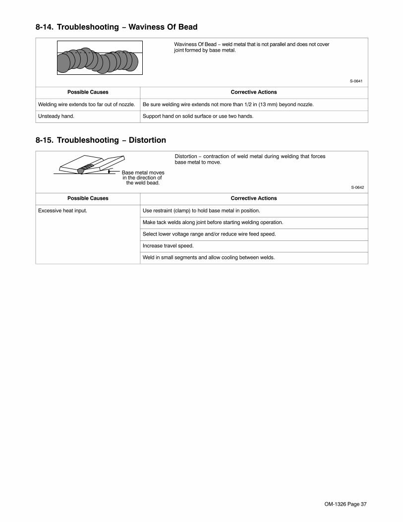
OM-1326 Page 37
8-14. Troubleshooting − Waviness Of Bead
Waviness Of Bead − weld metal that is not parallel and does not coverjoint formed by base metal.
S-0641
Possible Causes Corrective Actions
Welding wire extends too far out of nozzle. Be sure welding wire extends not more than 1/2 in (13 mm) beyond nozzle.
Unsteady hand. Support hand on solid surface or use two hands.
8-15. Troubleshooting − Distortion
Distortion − contraction of weld metal during welding that forcesbase metal to move.
Base metal movesin the direction of
the weld bead.S-0642
Possible Causes Corrective Actions
Excessive heat input. Use restraint (clamp) to hold base metal in position.
Make tack welds along joint before starting welding operation.
Select lower voltage range and/or reduce wire feed speed.
Increase travel speed.
Weld in small segments and allow cooling between welds.

OM-1326 Page 38
8-16. Common MIG Shielding GasesThis is a general chart for common gases and where they are used. Many different combinations (mixtures) ofshielding gases have been developed over the years. The most commonly used shielding gases are listed in thefollowing table.
Application
GasSpray Arc Steel Short Circuiting Steel
Short CircuitingStainless Steel
Aluminum
Argon X
Argon + 25% CO2 X
80% or greater Argon +balance CO2 or Oxygen
X X1
100% CO2 X
Tri-Mix2 X1 Limited short circuiting use
2 90% HE + 7-1/2% AR + 2-1/2% CO2
8-17. Troubleshooting Guide For Semiautomatic Welding Equipment
Problem Probable Cause Remedy
Wire feed motor operates, butwire does not feed
Too little pressure on wire feed rolls. Increase pressure setting on wire feed rolls.wire does not feed.
Incorrect wire feed rolls. Check size stamped on wire feed rolls, replace to matchwire size and type if necessary.
Wire spool brake pressure too high. Decrease brake pressure on wire spool.
Restriction in the gun and/or assembly. Check and replace cable, gun, and contact tip ifdamaged. Check size of contact tip and cable liner,replace if necessary.
Wire curling up in front of thewire feed rolls (bird nesting)
Too much pressure on wire feed rolls. Decrease pressure setting on wire feed rolls.wire feed rolls (bird nesting).
Incorrect cable liner or gun contact tip size. Check size of contact tip and check cable liner lengthand diameter, replace if necessary.
Gun end not inserted into drive housing properly. Loosen gun securing bolt in drive housing and push gunend into housing just enough so it does not touch wirefeed rolls.
Dirty or damaged (kinked) liner. Replace liner.
Wire feeds, but no gas flows. Gas cylinder empty. Replace empty gas cylinder.
Gas nozzle plugged. Clean or replace gas nozzle.
Gas cylinder valve not open or flowmeter not adjusted. Open gas valve at cylinder and adjust flow rate.
Restriction in gas line. Check gas hose between flowmeter and wire feeder, andgas hose in gun and cable assembly.
Loose or broken wires to gas solenoid. Have Factory Authorized Service Agent repair wiring.
Gas solenoid valve not operating. Have Factory Authorized Service Agent replace gassolenoid valve.
Incorrect primary voltage connected to welding powersource.
Check primary voltage and relink welding power sourcefor correct voltage.

OM-1326 Page 39
Problem RemedyProbable Cause
Welding arc not stable. Wire slipping in drive rolls. Adjust pressure setting on wire feed rolls. Replace worndrive rolls if necessary.
Wrong size gun liner or contact tip. Match liner and contact tip to wire size and type.
Incorrect voltage setting for selected wire feed speed onwelding power source.
Readjust welding parameters.
Loose connections at the gun weld cable or work cable. Check and tighten all connections.
Gun in poor shape or loose connection inside gun. Repair or replace gun as necessary.
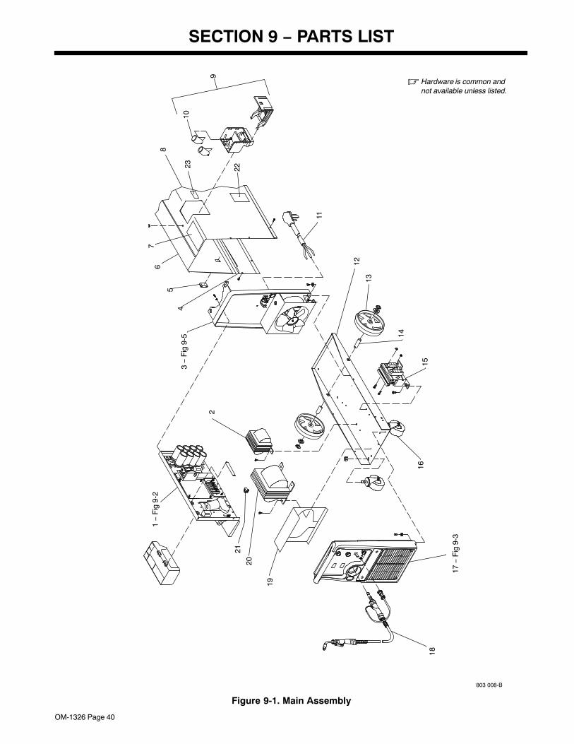
OM-1326 Page 40
SECTION 9 − PARTS LIST
803 008-B
� Hardware is common andnot available unless listed.
20
21
23
1516
14
13
12
22
45
6
10
11
7
8
9
19
2
1 −
Fig
9-2
17 −
Fig
9-3
3 −
Fig
9-5
18
Figure 9-1. Main Assembly
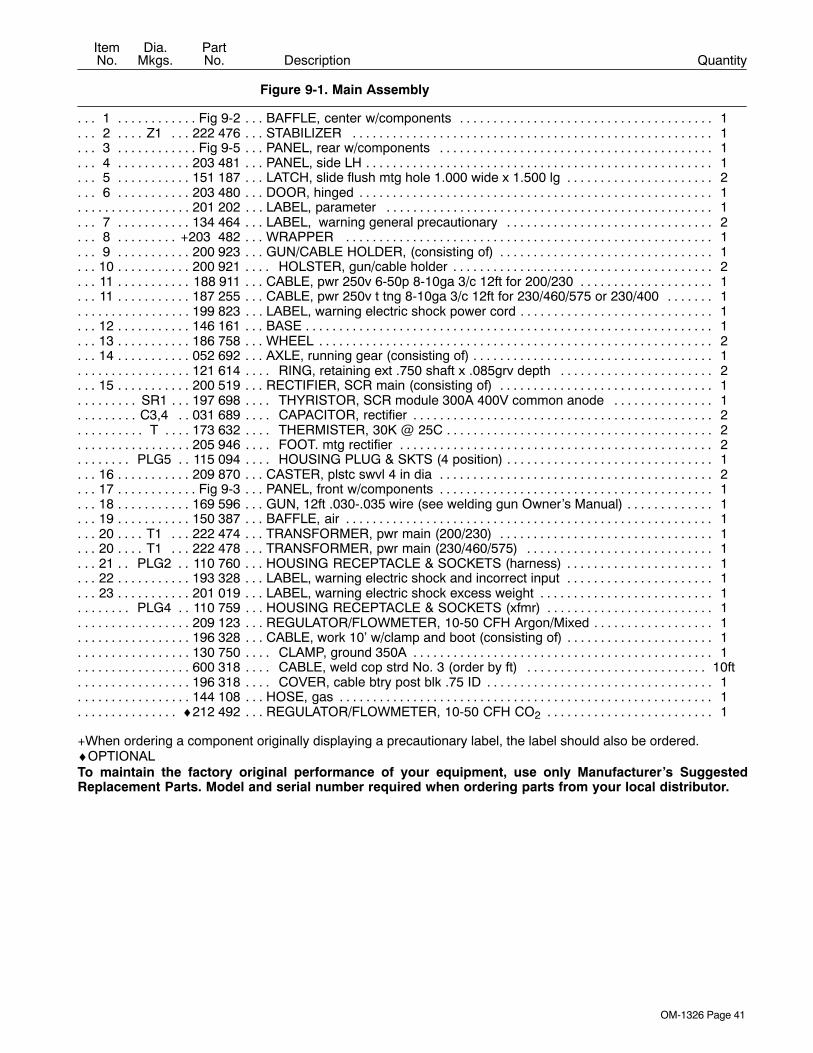
OM-1326 Page 41
DescriptionPartNo.
Dia.Mkgs.
ItemNo.
Figure 9-1. Main Assembly
Quantity
1 Fig 9-2 BAFFLE, center w/components 1. . . . . . . . . . . . . . . . . . . . . . . . . . . . . . . . . . . . . . . . . . . . . . . . . . . . . . . . 2 Z1 222 476 STABILIZER 1. . . . . . . . . . . . . . . . . . . . . . . . . . . . . . . . . . . . . . . . . . . . . . . . . . . . . . . . . . . . . . . . . . . 3 Fig 9-5 PANEL, rear w/components 1. . . . . . . . . . . . . . . . . . . . . . . . . . . . . . . . . . . . . . . . . . . . . . . . . . . . . . . . . . . 4 203 481 PANEL, side LH 1. . . . . . . . . . . . . . . . . . . . . . . . . . . . . . . . . . . . . . . . . . . . . . . . . . . . . . . . . . . . . . . . . . . . . 5 151 187 LATCH, slide flush mtg hole 1.000 wide x 1.500 lg 2. . . . . . . . . . . . . . . . . . . . . . . . . . . . . . . . . . . . . . . 6 203 480 DOOR, hinged 1. . . . . . . . . . . . . . . . . . . . . . . . . . . . . . . . . . . . . . . . . . . . . . . . . . . . . . . . . . . . . . . . . . . . . .
201 202 LABEL, parameter 1. . . . . . . . . . . . . . . . . . . . . . . . . . . . . . . . . . . . . . . . . . . . . . . . . . . . . . . . . . . . . . . . . . . . . 7 134 464 LABEL, warning general precautionary 2. . . . . . . . . . . . . . . . . . . . . . . . . . . . . . . . . . . . . . . . . . . . . . . . 8 +203 482 WRAPPER 1. . . . . . . . . . . . . . . . . . . . . . . . . . . . . . . . . . . . . . . . . . . . . . . . . . . . . . . . . . . . . . . . . . . . . . 9 200 923 GUN/CABLE HOLDER, (consisting of) 1. . . . . . . . . . . . . . . . . . . . . . . . . . . . . . . . . . . . . . . . . . . . . . . . .
10 200 921 HOLSTER, gun/cable holder 2. . . . . . . . . . . . . . . . . . . . . . . . . . . . . . . . . . . . . . . . . . . . . . . . . . . . . . . . . 11 188 911 CABLE, pwr 250v 6-50p 8-10ga 3/c 12ft for 200/230 1. . . . . . . . . . . . . . . . . . . . . . . . . . . . . . . . . . . . . 11 187 255 CABLE, pwr 250v t tng 8-10ga 3/c 12ft for 230/460/575 or 230/400 1. . . . . . . . . . . . . . . . . . . . . . . .
199 823 LABEL, warning electric shock power cord 1. . . . . . . . . . . . . . . . . . . . . . . . . . . . . . . . . . . . . . . . . . . . . . . . . 12 146 161 BASE 1. . . . . . . . . . . . . . . . . . . . . . . . . . . . . . . . . . . . . . . . . . . . . . . . . . . . . . . . . . . . . . . . . . . . . . . . . . . . . . 13 186 758 WHEEL 2. . . . . . . . . . . . . . . . . . . . . . . . . . . . . . . . . . . . . . . . . . . . . . . . . . . . . . . . . . . . . . . . . . . . . . . . . . . . 14 052 692 AXLE, running gear (consisting of) 1. . . . . . . . . . . . . . . . . . . . . . . . . . . . . . . . . . . . . . . . . . . . . . . . . . . . .
121 614 RING, retaining ext .750 shaft x .085grv depth 2. . . . . . . . . . . . . . . . . . . . . . . . . . . . . . . . . . . . . . . . . . . . 15 200 519 RECTIFIER, SCR main (consisting of) 1. . . . . . . . . . . . . . . . . . . . . . . . . . . . . . . . . . . . . . . . . . . . . . . . .
SR1 197 698 THYRISTOR, SCR module 300A 400V common anode 1. . . . . . . . . . . . . . . . . . . . . . . . . . . . . . . C3,4 031 689 CAPACITOR, rectifier 2. . . . . . . . . . . . . . . . . . . . . . . . . . . . . . . . . . . . . . . . . . . . . . . . . . . . . . . . . . . .
T 173 632 THERMISTER, 30K @ 25C 2. . . . . . . . . . . . . . . . . . . . . . . . . . . . . . . . . . . . . . . . . . . . . . . . . . . . . . . . . . 205 946 FOOT. mtg rectifier 2. . . . . . . . . . . . . . . . . . . . . . . . . . . . . . . . . . . . . . . . . . . . . . . . . . . . . . . . . . . . . . . . . . . .
PLG5 115 094 HOUSING PLUG & SKTS (4 position) 1. . . . . . . . . . . . . . . . . . . . . . . . . . . . . . . . . . . . . . . . . . . . . 16 209 870 CASTER, plstc swvl 4 in dia 2. . . . . . . . . . . . . . . . . . . . . . . . . . . . . . . . . . . . . . . . . . . . . . . . . . . . . . . . . . 17 Fig 9-3 PANEL, front w/components 1. . . . . . . . . . . . . . . . . . . . . . . . . . . . . . . . . . . . . . . . . . . . . . . . . . . . . . . . . . . 18 169 596 GUN, 12ft .030-.035 wire (see welding gun Owner’s Manual) 1. . . . . . . . . . . . . . . . . . . . . . . . . . . . . . 19 150 387 BAFFLE, air 1. . . . . . . . . . . . . . . . . . . . . . . . . . . . . . . . . . . . . . . . . . . . . . . . . . . . . . . . . . . . . . . . . . . . . . . . 20 T1 222 474 TRANSFORMER, pwr main (200/230) 1. . . . . . . . . . . . . . . . . . . . . . . . . . . . . . . . . . . . . . . . . . . . . 20 T1 222 478 TRANSFORMER, pwr main (230/460/575) 1. . . . . . . . . . . . . . . . . . . . . . . . . . . . . . . . . . . . . . . . . 21 PLG2 110 760 HOUSING RECEPTACLE & SOCKETS (harness) 1. . . . . . . . . . . . . . . . . . . . . . . . . . . . . . . . 22 193 328 LABEL, warning electric shock and incorrect input 1. . . . . . . . . . . . . . . . . . . . . . . . . . . . . . . . . . . . . . . 23 201 019 LABEL, warning electric shock excess weight 1. . . . . . . . . . . . . . . . . . . . . . . . . . . . . . . . . . . . . . . . . . .
PLG4 110 759 HOUSING RECEPTACLE & SOCKETS (xfmr) 1. . . . . . . . . . . . . . . . . . . . . . . . . . . . . . . . . . . . . . 209 123 REGULATOR/FLOWMETER, 10-50 CFH Argon/Mixed 1. . . . . . . . . . . . . . . . . . . . . . . . . . . . . . . . . . . . . . 196 328 CABLE, work 10’ w/clamp and boot (consisting of) 1. . . . . . . . . . . . . . . . . . . . . . . . . . . . . . . . . . . . . . . . . . 130 750 CLAMP, ground 350A 1. . . . . . . . . . . . . . . . . . . . . . . . . . . . . . . . . . . . . . . . . . . . . . . . . . . . . . . . . . . . . . . . . . 600 318 CABLE, weld cop strd No. 3 (order by ft) 10ft. . . . . . . . . . . . . . . . . . . . . . . . . . . . . . . . . . . . . . . . . . . . . . . . 196 318 COVER, cable btry post blk .75 ID 1. . . . . . . . . . . . . . . . . . . . . . . . . . . . . . . . . . . . . . . . . . . . . . . . . . . . . . . 144 108 HOSE, gas 1. . . . . . . . . . . . . . . . . . . . . . . . . . . . . . . . . . . . . . . . . . . . . . . . . . . . . . . . . . . . . . . . . . . . . . . . . . . .
♦212 492 REGULATOR/FLOWMETER, 10-50 CFH CO2 1. . . . . . . . . . . . . . . . . . . . . . . . . . . . . . . . . . . . . . . . . . .
+When ordering a component originally displaying a precautionary label, the label should also be ordered.♦OPTIONALTo maintain the factory original performance of your equipment, use only Manufacturer’s SuggestedReplacement Parts. Model and serial number required when ordering parts from your local distributor.
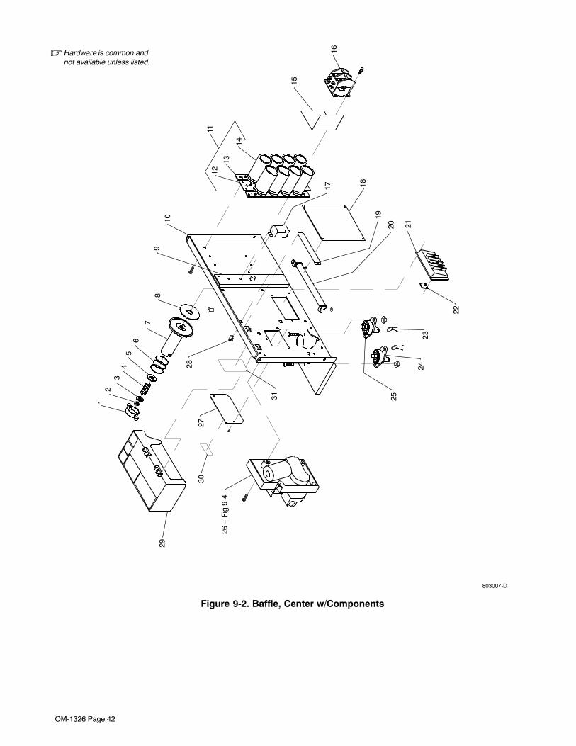
OM-1326 Page 42
803007-D
� Hardware is common andnot available unless listed.
12
34
56
78
910
1112
13
14
15
1617 18
19
20 21
22
2324
25
27
28
29
30
31
26 −
Fig
9-4
Figure 9-2. Baffle, Center w/Components

OM-1326 Page 43
DescriptionPartNo.
Dia.Mkgs.
ItemNo.
Figure 9-2. Baffle, Center w/Components (Fig 9-1 Item 1)
Quantity
1 058 427 RING, retaining spool 1. . . . . . . . . . . . . . . . . . . . . . . . . . . . . . . . . . . . . . . . . . . . . . . . . . . . . . . . . . . . . . . . 2 085 980 NUT, stl hex full .625-11 1. . . . . . . . . . . . . . . . . . . . . . . . . . . . . . . . . . . . . . . . . . . . . . . . . . . . . . . . . . . . . . 3 605 941 WASHER, flat stl .640 ID x 1.000 OD x 14ga thk 1. . . . . . . . . . . . . . . . . . . . . . . . . . . . . . . . . . . . . . . . 4 186 437 SPRING, cprsn .845 OD x .110 wire x 1.500 1. . . . . . . . . . . . . . . . . . . . . . . . . . . . . . . . . . . . . . . . . . . . 5 057 971 WASHER, flat stl keyed 1.500dia x .125thk 1. . . . . . . . . . . . . . . . . . . . . . . . . . . . . . . . . . . . . . . . . . . . . 6 057 745 SPRING, cprsn 2.430 OD x .090 wire x 2.500 1. . . . . . . . . . . . . . . . . . . . . . . . . . . . . . . . . . . . . . . . . . . 7 186 435 HUB, spool 1. . . . . . . . . . . . . . . . . . . . . . . . . . . . . . . . . . . . . . . . . . . . . . . . . . . . . . . . . . . . . . . . . . . . . . . . . 8 186 436 WASHER, brake 1. . . . . . . . . . . . . . . . . . . . . . . . . . . . . . . . . . . . . . . . . . . . . . . . . . . . . . . . . . . . . . . . . . . . 9 177 307 REEL, support 1. . . . . . . . . . . . . . . . . . . . . . . . . . . . . . . . . . . . . . . . . . . . . . . . . . . . . . . . . . . . . . . . . . . . . .
198425 CAP, finishing 1.19 X .37 2. . . . . . . . . . . . . . . . . . . . . . . . . . . . . . . . . . . . . . . . . . . . . . . . . . . . . . . . . . . . . . . . 198426 WASHER, cap 2. . . . . . . . . . . . . . . . . . . . . . . . . . . . . . . . . . . . . . . . . . . . . . . . . . . . . . . . . . . . . . . . . . . . . . . . .
10 211 413 BAFFLE, center 1. . . . . . . . . . . . . . . . . . . . . . . . . . . . . . . . . . . . . . . . . . . . . . . . . . . . . . . . . . . . . . . . . . . . . 11 186 998 CAPACITOR ASSEMBLY KIT, (consisting of) 1. . . . . . . . . . . . . . . . . . . . . . . . . . . . . . . . . . . . . . . . . . . 12 082 902 STRIP, mtg center capacitor 1. . . . . . . . . . . . . . . . . . . . . . . . . . . . . . . . . . . . . . . . . . . . . . . . . . . . . . . . . 13 185 643 STRIP, mtg capacitors 2. . . . . . . . . . . . . . . . . . . . . . . . . . . . . . . . . . . . . . . . . . . . . . . . . . . . . . . . . . . . . .
083 147 GROMMET, scr No. 8/10 panel hole .312sq .500 high 6. . . . . . . . . . . . . . . . . . . . . . . . . . . . . . . . . . . . . . 14 C5 184 584 CAPACITOR, elctlt 15000uf 45VDC 8. . . . . . . . . . . . . . . . . . . . . . . . . . . . . . . . . . . . . . . . . . . . . . .
187 752 INSULATOR, capacitor 1. . . . . . . . . . . . . . . . . . . . . . . . . . . . . . . . . . . . . . . . . . . . . . . . . . . . . . . . . . . . . . . . . 15 204 318 BRACKET, mtg 1. . . . . . . . . . . . . . . . . . . . . . . . . . . . . . . . . . . . . . . . . . . . . . . . . . . . . . . . . . . . . . . . . . . . . 16 W 204 319 CONTACTOR, def prp 25A 2P 36VDC 1. . . . . . . . . . . . . . . . . . . . . . . . . . . . . . . . . . . . . . . . . . . . . 17 CR1 052 964 RELAY, 24V DPDT 10A/120VAC 1. . . . . . . . . . . . . . . . . . . . . . . . . . . . . . . . . . . . . . . . . . . . . . . . .
VR1 144 425 VARISTOR, w/leads 1. . . . . . . . . . . . . . . . . . . . . . . . . . . . . . . . . . . . . . . . . . . . . . . . . . . . . . . . . . . . . . . 18 PC1 220 069 CIRCUIT CARD, control 1. . . . . . . . . . . . . . . . . . . . . . . . . . . . . . . . . . . . . . . . . . . . . . . . . . . . . . . .
PLG1 162 382 HOUSING PLUG & SOCKETS 1. . . . . . . . . . . . . . . . . . . . . . . . . . . . . . . . . . . . . . . . . . . . . . . . . . . PLG3 130 203 HOUSING RECEPTACLE & SOCKETS 1. . . . . . . . . . . . . . . . . . . . . . . . . . . . . . . . . . . . . . . . . . . . PLG7 115 092 HOUSING RECEPTACLE & SOCKETS 1. . . . . . . . . . . . . . . . . . . . . . . . . . . . . . . . . . . . . . . . . . . . PLG8 115 093 HOUSING PLUG & SOCKETS 1. . . . . . . . . . . . . . . . . . . . . . . . . . . . . . . . . . . . . . . . . . . . . . . . . . .
19 196 894 COVER 1. . . . . . . . . . . . . . . . . . . . . . . . . . . . . . . . . . . . . . . . . . . . . . . . . . . . . . . . . . . . . . . . . . . . . . . . . . . 20 R1 119 998 RESISTOR, WW fxd 300W 5 ohm 1. . . . . . . . . . . . . . . . . . . . . . . . . . . . . . . . . . . . . . . . . . . . . . . . . 21 TE1 188 910 TERMINAL ASSEMBLY, pri 1ph double voltage (200/230 or 230/400) 1. . . . . . . . . . . . . . . . . 21 TE1 192 907 TERMINAL ASSEMBLY, pri 1ph triple voltage (230/460/575) 1. . . . . . . . . . . . . . . . . . . . . . . . 22 038 618 LINK, jumper term bd pri as req.. . . . . . . . . . . . . . . . . . . . . . . . . . . . . . . . . . . . . . . . . . . . . . . . . . . . . . . . . . . 23 C7,8 128 750 CAPACITOR 2. . . . . . . . . . . . . . . . . . . . . . . . . . . . . . . . . . . . . . . . . . . . . . . . . . . . . . . . . . . . . . . . . 24 POS 097 421 TERMINAL, pwr output red 1. . . . . . . . . . . . . . . . . . . . . . . . . . . . . . . . . . . . . . . . . . . . . . . . . . . . . 25 NEG 097 416 TERMINAL, pwr output black 1. . . . . . . . . . . . . . . . . . . . . . . . . . . . . . . . . . . . . . . . . . . . . . . . . . . 26 Fig 9-4 WIRE DRIVE & GEARS 1. . . . . . . . . . . . . . . . . . . . . . . . . . . . . . . . . . . . . . . . . . . . . . . . . . . . . . . . . . . . . . 27 188 917 DOOR, access changeover 1. . . . . . . . . . . . . . . . . . . . . . . . . . . . . . . . . . . . . . . . . . . . . . . . . . . . . . . . . . . 28 134 201 STAND-OFF SUPPORT, PC card 4. . . . . . . . . . . . . . . . . . . . . . . . . . . . . . . . . . . . . . . . . . . . . . . . . . . . . 29 197 555 TOOL TRAY 1. . . . . . . . . . . . . . . . . . . . . . . . . . . . . . . . . . . . . . . . . . . . . . . . . . . . . . . . . . . . . . . . . . . . . . . . 30 021 469 LABEL, warning high voltage 1. . . . . . . . . . . . . . . . . . . . . . . . . . . . . . . . . . . . . . . . . . . . . . . . . . . . . . . . . 31 199 824 LABEL, warning electric shock and pinch points 1. . . . . . . . . . . . . . . . . . . . . . . . . . . . . . . . . . . . . . . . .
+When ordering a component originally displaying a precautionary label, the label should also be ordered.To maintain the factory original performance of your equipment, use only Manufacturer’s SuggestedReplacement Parts. Model and serial number required when ordering parts from your local distributor.
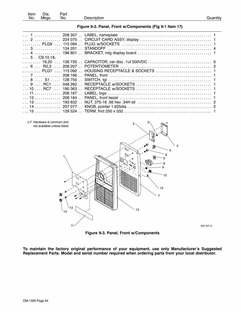
OM-1326 Page 44
DescriptionPartNo.
Dia.Mkgs.
ItemNo.
Figure 9-3. Panel, Front w/Components (Fig 9-1 Item 17)
Quantity
1 208 357 LABEL, nameplate 1. . . . . . . . . . . . . . . . . . . . . . . . . . . . . . . . . . . . . . . . . . . . . . . . . . . . . . . . . . . . . . . . 2 224 075 CIRCUIT CARD ASSY, display 1. . . . . . . . . . . . . . . . . . . . . . . . . . . . . . . . . . . . . . . . . . . . . . . . . . . . . .
PLG9 115 094 PLUG w/SOCKETS 1. . . . . . . . . . . . . . . . . . . . . . . . . . . . . . . . . . . . . . . . . . . . . . . . . . . . . . . . . . . . 3 134 201 STANDOFF 4. . . . . . . . . . . . . . . . . . . . . . . . . . . . . . . . . . . . . . . . . . . . . . . . . . . . . . . . . . . . . . . . . . . . . . 4 196 801 BRACKET, mtg display board 1. . . . . . . . . . . . . . . . . . . . . . . . . . . . . . . . . . . . . . . . . . . . . . . . . . . . . . . 5 C9,10,18,. . . .
19,20 136 735 CAPACITOR, cer disc .1uf 500VDC 5. . . . . . . . . . . . . . . . . . . . . . . . . . . . . . . . . . . . . . . . . . . . . . 6 R2,3 208 207 POTENTIOMETER 2. . . . . . . . . . . . . . . . . . . . . . . . . . . . . . . . . . . . . . . . . . . . . . . . . . . . . . . . . .
PLG7 115 092 HOUSING RECEPTACLE & SOCKETS 1. . . . . . . . . . . . . . . . . . . . . . . . . . . . . . . . . . . . . . . . . . . 7 208 166 PANEL, front 1. . . . . . . . . . . . . . . . . . . . . . . . . . . . . . . . . . . . . . . . . . . . . . . . . . . . . . . . . . . . . . . . . . . . . 8 S1 128 755 SWITCH, tgl 1. . . . . . . . . . . . . . . . . . . . . . . . . . . . . . . . . . . . . . . . . . . . . . . . . . . . . . . . . . . . . . . . . . 9 RC1 048 282 RECEPTACLE w/SOCKETS 1. . . . . . . . . . . . . . . . . . . . . . . . . . . . . . . . . . . . . . . . . . . . . . . . . . .
10 RC7 190 363 RECEPTACLE w/SOCKETS 1. . . . . . . . . . . . . . . . . . . . . . . . . . . . . . . . . . . . . . . . . . . . . . . . . . . 11 208 167 LABEL, logo 1. . . . . . . . . . . . . . . . . . . . . . . . . . . . . . . . . . . . . . . . . . . . . . . . . . . . . . . . . . . . . . . . . . . . . . 12 208 164 PANEL, front bezel 1. . . . . . . . . . . . . . . . . . . . . . . . . . . . . . . . . . . . . . . . . . . . . . . . . . . . . . . . . . . . . . . . 13 193 632 NUT, 375-16 .56 hex .34H stl 2. . . . . . . . . . . . . . . . . . . . . . . . . . . . . . . . . . . . . . . . . . . . . . . . . . . . . . . 14 207 077 KNOB, pointer 1.625dia 2. . . . . . . . . . . . . . . . . . . . . . . . . . . . . . . . . . . . . . . . . . . . . . . . . . . . . . . . . . . . 15 129 524 TERM, frict 250 x 032 1. . . . . . . . . . . . . . . . . . . . . . . . . . . . . . . . . . . . . . . . . . . . . . . . . . . . . . . . . . . . . .
� Hardware is common andnot available unless listed.
803 307-A
1
2 3
45
65
89
10
15
7
12
11
1413
Figure 9-3. Panel, Front w/Components
To maintain the factory original performance of your equipment, use only Manufacturer’s SuggestedReplacement Parts. Model and serial number required when ordering parts from your local distributor.
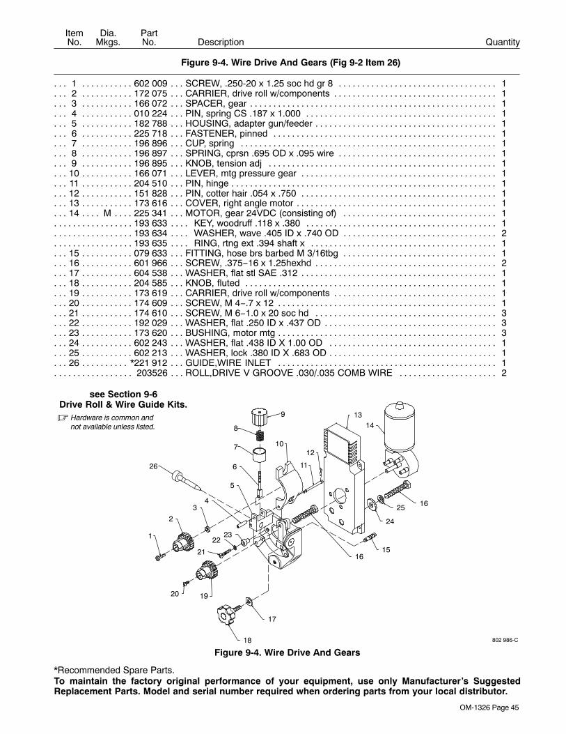
OM-1326 Page 45
DescriptionPartNo.
Dia.Mkgs.
ItemNo.
Figure 9-4. Wire Drive And Gears (Fig 9-2 Item 26)
Quantity
1 602 009 SCREW, .250-20 x 1.25 soc hd gr 8 1. . . . . . . . . . . . . . . . . . . . . . . . . . . . . . . . . . . . . . . . . . . . . . . . . . . 2 172 075 CARRIER, drive roll w/components 1. . . . . . . . . . . . . . . . . . . . . . . . . . . . . . . . . . . . . . . . . . . . . . . . . . . . 3 166 072 SPACER, gear 1. . . . . . . . . . . . . . . . . . . . . . . . . . . . . . . . . . . . . . . . . . . . . . . . . . . . . . . . . . . . . . . . . . . . . . 4 010 224 PIN, spring CS .187 x 1.000 1. . . . . . . . . . . . . . . . . . . . . . . . . . . . . . . . . . . . . . . . . . . . . . . . . . . . . . . . . . 5 182 788 HOUSING, adapter gun/feeder 1. . . . . . . . . . . . . . . . . . . . . . . . . . . . . . . . . . . . . . . . . . . . . . . . . . . . . . . . 6 225 718 FASTENER, pinned 1. . . . . . . . . . . . . . . . . . . . . . . . . . . . . . . . . . . . . . . . . . . . . . . . . . . . . . . . . . . . . . . . . 7 196 896 CUP, spring 1. . . . . . . . . . . . . . . . . . . . . . . . . . . . . . . . . . . . . . . . . . . . . . . . . . . . . . . . . . . . . . . . . . . . . . . . 8 196 897 SPRING, cprsn .695 OD x .095 wire 1. . . . . . . . . . . . . . . . . . . . . . . . . . . . . . . . . . . . . . . . . . . . . . . . . . . 9 196 895 KNOB, tension adj 1. . . . . . . . . . . . . . . . . . . . . . . . . . . . . . . . . . . . . . . . . . . . . . . . . . . . . . . . . . . . . . . . . .
10 166 071 LEVER, mtg pressure gear 1. . . . . . . . . . . . . . . . . . . . . . . . . . . . . . . . . . . . . . . . . . . . . . . . . . . . . . . . . . . 11 204 510 PIN, hinge 1. . . . . . . . . . . . . . . . . . . . . . . . . . . . . . . . . . . . . . . . . . . . . . . . . . . . . . . . . . . . . . . . . . . . . . . . . . 12 151 828 PIN, cotter hair .054 x .750 1. . . . . . . . . . . . . . . . . . . . . . . . . . . . . . . . . . . . . . . . . . . . . . . . . . . . . . . . . . . 13 173 616 COVER, right angle motor 1. . . . . . . . . . . . . . . . . . . . . . . . . . . . . . . . . . . . . . . . . . . . . . . . . . . . . . . . . . . . 14 M 225 341 MOTOR, gear 24VDC (consisting of) 1. . . . . . . . . . . . . . . . . . . . . . . . . . . . . . . . . . . . . . . . . . . . . . .
193 633 KEY, woodruff .118 x .380 1. . . . . . . . . . . . . . . . . . . . . . . . . . . . . . . . . . . . . . . . . . . . . . . . . . . . . . . . . . . . . . 193 634 WASHER, wave .405 ID x .740 OD 2. . . . . . . . . . . . . . . . . . . . . . . . . . . . . . . . . . . . . . . . . . . . . . . . . . . . . . 193 635 RING, rtng ext .394 shaft x 1. . . . . . . . . . . . . . . . . . . . . . . . . . . . . . . . . . . . . . . . . . . . . . . . . . . . . . . . . . . . .
15 079 633 FITTING, hose brs barbed M 3/16tbg 1. . . . . . . . . . . . . . . . . . . . . . . . . . . . . . . . . . . . . . . . . . . . . . . . . . 16 601 966 SCREW, .375−16 x 1.25hexhd 2. . . . . . . . . . . . . . . . . . . . . . . . . . . . . . . . . . . . . . . . . . . . . . . . . . . . . . . . 17 604 538 WASHER, flat stl SAE .312 1. . . . . . . . . . . . . . . . . . . . . . . . . . . . . . . . . . . . . . . . . . . . . . . . . . . . . . . . . . . 18 204 585 KNOB, fluted 1. . . . . . . . . . . . . . . . . . . . . . . . . . . . . . . . . . . . . . . . . . . . . . . . . . . . . . . . . . . . . . . . . . . . . . . 19 173 619 CARRIER, drive roll w/components 1. . . . . . . . . . . . . . . . . . . . . . . . . . . . . . . . . . . . . . . . . . . . . . . . . . . . 20 174 609 SCREW, M 4−.7 x 12 1. . . . . . . . . . . . . . . . . . . . . . . . . . . . . . . . . . . . . . . . . . . . . . . . . . . . . . . . . . . . . . . . 21 174 610 SCREW, M 6−1.0 x 20 soc hd 3. . . . . . . . . . . . . . . . . . . . . . . . . . . . . . . . . . . . . . . . . . . . . . . . . . . . . . . . 22 192 029 WASHER, flat .250 ID x .437 OD 3. . . . . . . . . . . . . . . . . . . . . . . . . . . . . . . . . . . . . . . . . . . . . . . . . . . . . . 23 173 620 BUSHING, motor mtg 3. . . . . . . . . . . . . . . . . . . . . . . . . . . . . . . . . . . . . . . . . . . . . . . . . . . . . . . . . . . . . . . . 24 602 243 WASHER, flat .438 ID X 1.00 OD 1. . . . . . . . . . . . . . . . . . . . . . . . . . . . . . . . . . . . . . . . . . . . . . . . . . . . . 25 602 213 WASHER, lock .380 ID X .683 OD 1. . . . . . . . . . . . . . . . . . . . . . . . . . . . . . . . . . . . . . . . . . . . . . . . . . . . . 26 *221 912 GUIDE,WIRE INLET 1. . . . . . . . . . . . . . . . . . . . . . . . . . . . . . . . . . . . . . . . . . . . . . . . . . . . . . . . . . . . . . .
203526 ROLL,DRIVE V GROOVE .030/.035 COMB WIRE 2. . . . . . . . . . . . . . . . . . . . . . . . . . . . . . . . . . . . . . . . .
� Hardware is common andnot available unless listed.
802 986-C
see Section 9-6Drive Roll & Wire Guide Kits.
9
8
7
16
25
24
2322
21
20 19
18
17
16
15
1413
12
11
10
6
5
43
2
1
26
Figure 9-4. Wire Drive And Gears
*Recommended Spare Parts.To maintain the factory original performance of your equipment, use only Manufacturer’s SuggestedReplacement Parts. Model and serial number required when ordering parts from your local distributor.
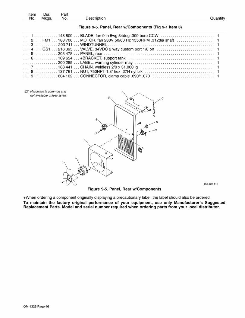
OM-1326 Page 46
DescriptionPartNo.
Dia.Mkgs.
ItemNo.
Figure 9-5. Panel, Rear w/Components (Fig 9-1 Item 3)
Quantity
1 148 809 BLADE, fan 9 in 5wg 34deg .309 bore CCW 1. . . . . . . . . . . . . . . . . . . . . . . . . . . . . . . . . . . . . . . . . . . . 2 FM1 188 706 MOTOR, fan 230V 50/60 Hz 1550RPM .312dia shaft 1. . . . . . . . . . . . . . . . . . . . . . . . . . . . . . . 3 203 711 WINDTUNNEL 1. . . . . . . . . . . . . . . . . . . . . . . . . . . . . . . . . . . . . . . . . . . . . . . . . . . . . . . . . . . . . . . . . . . . . . 4 GS1 216 395 VALVE, 34VDC 2 way custom port 1/8 orf 1. . . . . . . . . . . . . . . . . . . . . . . . . . . . . . . . . . . . . . . . . 5 203 478 PANEL, rear 1. . . . . . . . . . . . . . . . . . . . . . . . . . . . . . . . . . . . . . . . . . . . . . . . . . . . . . . . . . . . . . . . . . . . . . . . 6 169 654 +BRACKET, support tank 1. . . . . . . . . . . . . . . . . . . . . . . . . . . . . . . . . . . . . . . . . . . . . . . . . . . . . . . . . . . .
200 285 LABEL, warning cylinder may 1. . . . . . . . . . . . . . . . . . . . . . . . . . . . . . . . . . . . . . . . . . . . . . . . . . . . . . . . . . . . 7 188 441 CHAIN, weldless 2/0 x 31.000 lg 1. . . . . . . . . . . . . . . . . . . . . . . . . . . . . . . . . . . . . . . . . . . . . . . . . . . . . . 8 137 761 NUT, 750NPT 1.31hex .27H nyl blk 1. . . . . . . . . . . . . . . . . . . . . . . . . . . . . . . . . . . . . . . . . . . . . . . . . . . . 9 604 102 CONNECTOR, clamp cable .690/1.070 1. . . . . . . . . . . . . . . . . . . . . . . . . . . . . . . . . . . . . . . . . . . . . . . .
Ref. 803 011
� Hardware is common andnot available unless listed.
12
3
4
5
6
7
8
9
Figure 9-5. Panel, Rear w/Components
+When ordering a component originally displaying a precautionary label, the label should also be ordered.To maintain the factory original performance of your equipment, use only Manufacturer’s SuggestedReplacement Parts. Model and serial number required when ordering parts from your local distributor.

OM-1326 Page 47
9-6. Drive Roll And Wire Guide Kits
Note Base selection of drive rolls upon the following recommended usages:
1 V-Grooved rolls for hard wire.
2 U-Grooved rolls for soft and soft shelled cored wires.
3 U-Cogged rolls for extremely soft shelled wires (usually hard surfacing types).4 V-Knurled rolls for hard shelled cored wires.
5 Drive roll types may be mixed to suit particular requirements (example: V-Knurled roll in combinationwith U-Grooved).
Ref. S-0026-B/7-91
Wire Diameter
Fraction Decimal Metric
.023/.025 in.
.030 in.
.035 in.
.045 in.
.023/.025 in.
.030 in.
.035 in.
.045 in.
0.6 mm
0.8 mm
0.9 mm
1.2 mm
Kit No.
087 131
079 594
079 595
079 596
Drive Roll
Part No. Type
087 130
053 695
053 700
053 697
V-Grooved
V-Grooved
V-Grooved
V-Grooved
Inlet
056 192
056 192
056 192
056 193
Wire Guide
.030/.035 in. .030/.035 in. 0.8/0.9 mm 204 579 203 526 V-Grooved 056 192

Notes

Notes

Notes
Warranty Questions?
Call1-800-4-A-MILLERfor your localMiller distributor.
miller_warr 2006−01
Your distributor also givesyou ...
ServiceYou always get the fast,reliable response youneed. Most replacementparts can be in yourhands in 24 hours.
SupportNeed fast answers to thetough welding questions?Contact your distributor.The expertise of thedistributor and Miller isthere to help you, everystep of the way.
Effective January 1, 2006(Equipment with a serial number preface of “LG” or newer)This limited warranty supersedes all previous Miller warranties and is exclusive with no other
guarantees or warranties expressed or implied.LIMITED WARRANTY − Subject to the terms and conditionsbelow, Miller Electric Mfg. Co., Appleton, Wisconsin, warrants toits original retail purchaser that new Miller equipment sold afterthe effective date of this limited warranty is free of defects inmaterial and workmanship at the time it is shipped by Miller. THISWARRANTY IS EXPRESSLY IN LIEU OF ALL OTHERWARRANTIES, EXPRESS OR IMPLIED, INCLUDING THEWARRANTIES OF MERCHANTABILITY AND FITNESS.
Within the warranty periods listed below, Miller will repair orreplace any warranted parts or components that fail due to suchdefects in material or workmanship. Miller must be notified inwriting within thirty (30) days of such defect or failure, at whichtime Miller will provide instructions on the warranty claimprocedures to be followed.
Miller shall honor warranty claims on warranted equipment listedbelow in the event of such a failure within the warranty timeperiods. All warranty time periods start on the date that theequipment was delivered to the original retail purchaser, or oneyear after the equipment is sent to a North American distributoror eighteen months after the equipment is sent to anInternational distributor.
1. 5 Years Parts — 3 Years Labor
* Original main power rectifiers
2. 3 Years — Parts and Labor
* Transformer/Rectifier Power Sources* Plasma Arc Cutting Power Sources* Process Controllers* Semi-Automatic and Automatic Wire Feeders* Inverter Power Sources (Unless Otherwise Stated)* Water Coolant Systems (Integrated)* Intellitig* Engine Driven Welding Generators
(NOTE: Engines are warranted separately by theengine manufacturer.)
3. 1 Year — Parts and Labor Unless Specified
* Motor Driven Guns (w/exception of SpoolmateSpoolguns)
* Positioners and Controllers* Automatic Motion Devices* RFCS Foot Controls* Induction Heating Power Sources, Coolers, and
ElectronicControls/Recorders
* Water Coolant Systems (Non-Integrated)* Flowgauge and Flowmeter Regulators (No Labor)* HF Units* Grids* Spot Welders* Load Banks* Arc Stud Power Sources & Arc Stud Guns* Racks* Running Gear/Trailers* Plasma Cutting Torches (except APT & SAF
Models)* Field Options
(NOTE: Field options are covered under True Blue®for the remaining warranty period of the product theyare installed in, or for a minimum of one year —whichever is greater.)
* Bernard-Branded Mig Guns (No Labor)* Weldcraft-Branded TIG Torches (No Labor)* Subarc Wire Drive Assemblies
4. 6 Months — Batteries
5. 90 Days — Parts
* MIG Guns/TIG Torches and Subarc (SAW) Guns
* Induction Heating Coils and Blankets, Cables, andNon-Electronic Controls
* APT & SAF Model Plasma Cutting Torches* Remote Controls* Accessory (Kits)* Replacement Parts (No labor)* Spoolmate Spoolguns* Canvas Covers
Miller’s True Blue® Limited Warranty shall not apply to:
1. Consumable components; such as contact tips,cutting nozzles, contactors, brushes, slip rings, relaysor parts that fail due to normal wear. (Exception:brushes, slip rings, and relays are covered on Bobcat,Trailblazer, and Legend models.)
2. Items furnished by Miller, but manufactured by others, suchas engines or trade accessories. These items are coveredby the manufacturer’s warranty, if any.
3. Equipment that has been modified by any party other thanMiller, or equipment that has been improperly installed,improperly operated or misused based upon industrystandards, or equipment which has not had reasonable andnecessary maintenance, or equipment which has beenused for operation outside of the specifications for theequipment.
MILLER PRODUCTS ARE INTENDED FOR PURCHASE ANDUSE BY COMMERCIAL/INDUSTRIAL USERS AND PERSONSTRAINED AND EXPERIENCED IN THE USE ANDMAINTENANCE OF WELDING EQUIPMENT.
In the event of a warranty claim covered by this warranty, theexclusive remedies shall be, at Miller’s option: (1) repair; or (2)replacement; or, where authorized in writing by Miller inappropriate cases, (3) the reasonable cost of repair orreplacement at an authorized Miller service station; or (4)payment of or credit for the purchase price (less reasonabledepreciation based upon actual use) upon return of the goods atcustomer’s risk and expense. Miller’s option of repair orreplacement will be F.O.B., Factory at Appleton, Wisconsin, orF.O.B. at a Miller authorized service facility as determined byMiller. Therefore no compensation or reimbursement fortransportation costs of any kind will be allowed.
TO THE EXTENT PERMITTED BY LAW, THE REMEDIESPROVIDED HEREIN ARE THE SOLE AND EXCLUSIVEREMEDIES. IN NO EVENT SHALL MILLER BE LIABLE FORDIRECT, INDIRECT, SPECIAL, INCIDENTAL ORCONSEQUENTIAL DAMAGES (INCLUDING LOSS OFPROFIT), WHETHER BASED ON CONTRACT, TORT OR ANYOTHER LEGAL THEORY.
ANY EXPRESS WARRANTY NOT PROVIDED HEREIN ANDANY IMPLIED WARRANTY, GUARANTY ORREPRESENTATION AS TO PERFORMANCE, AND ANYREMEDY FOR BREACH OF CONTRACT TORT OR ANYOTHER LEGAL THEORY WHICH, BUT FOR THISPROVISION, MIGHT ARISE BY IMPLICATION, OPERATIONOF LAW, CUSTOM OF TRADE OR COURSE OF DEALING,INCLUDING ANY IMPLIED WARRANTY OFMERCHANTABILITY OR FITNESS FOR PARTICULARPURPOSE, WITH RESPECT TO ANY AND ALL EQUIPMENTFURNISHED BY MILLER IS EXCLUDED AND DISCLAIMEDBY MILLER.
Some states in the U.S.A. do not allow limitations of how long animplied warranty lasts, or the exclusion of incidental, indirect,special or consequential damages, so the above limitation orexclusion may not apply to you. This warranty provides specificlegal rights, and other rights may be available, but may vary fromstate to state.
In Canada, legislation in some provinces provides for certainadditional warranties or remedies other than as stated herein,and to the extent that they may not be waived, the limitations andexclusions set out above may not apply. This Limited Warrantyprovides specific legal rights, and other rights may be available,but may vary from province to province.

PRINTED IN USA © 2006 Miller Electric Mfg. Co.2006−01
Miller Electric Mfg. Co.An Illinois Tool Works Company1635 West Spencer StreetAppleton, WI 54914 USA
International Headquarters−USAUSA Phone: 920-735-4505 Auto-AttendedUSA & Canada FAX: 920-735-4134International FAX: 920-735-4125
European Headquarters −United KingdomPhone: 44 (0) 1204-593493FAX: 44 (0) 1204-598066
www.MillerWelds.com
Model Name Serial/Style Number
Purchase Date (Date which equipment was delivered to original customer.)
Distributor
Address
City
State Zip
Please complete and retain with your personal records.
Always provide Model Name and Serial/Style Number.
Contact a DISTRIBUTOR or SERVICE AGENCY near you.
Welding Supplies and Consumables
Options and Accessories
Personal Safety Equipment
Service and Repair
Replacement Parts
Training (Schools, Videos, Books)
Technical Manuals (Servicing Informationand Parts)
Circuit Diagrams
Welding Process Handbooks
Contact the Delivering Carrier to:
For Service
Owner’s Record
File a claim for loss or damage duringshipment.
For assistance in filing or settling claims, contactyour distributor and/or equipment manufacturer’sTransportation Department.
Contact your Distributor for:
To locate a Distributor or Service Agency visitwww.millerwelds.com or call 1-800-4-A-Miller