MILITARY COMPUTERS
29
UNIVAC i/o description UNIVAC MILITARY COMPUTERS
Transcript of MILITARY COMPUTERS

$1=E~Y-<~ UNIVAC
i/o description UNIVAC MILITARY COMPUTERS

MILITARY COMPUTERS
i/o description
Si=EI«Y~~ UNIVAC DEFENSE SYSTEMS ST. PAUL, MINNESOTA 55165

CONTENTS
Page
INTRODUCTION ......................................... 1
FUNCTIONAL INTERFACE ............... a ••••••••••••••• 1
General Information .................................... 1 Control Communication ................................. 2 Defmition of Control Signals. . . . . . . . . . . . . . . . . . . . . . . . . . . . .. 3 Sequence of Input/Output Events .......................... 3
Data Output .................................... ' ..... 3 Function Output .... . ......... -. . .................. 4 Data Input . . . . . . . . . . . . . . . . . . . . . . . . . . . . . . . . . . . . . . . . .. 4 Interrupt Input ...................................... 5
COMPUTER-TO-COMPUTER INTERFACE .................... 6
Data and Control Signals . . . . . . . . . . . . . . . . . . . . . . . . . . . . . . . .. 6 Definition of Control Signals. . . . . . . . . . . . . . . . . . . . . . . . . . . . .. 6 Sequence of Events - Information Transfers ................. 6
Function Word Transfers (Commands) .. ' .................. 6 Data Transfers ...... . . . . . . . . . . . . . . . . . . . . . .. . . . . . . . .. . 7
ELECTRICAL INTERFACE ................................ 8
Input and Output Functional Specifications ......... ; ........ 8 Minus 15 Volt Interface - Input and
Output Circuit Specifications .............. ., ............ 9 General System Considerations ... . . . . . . . . . . . . . . . . . . . . .. 10
Minus 3 Volt Interface - Input and Output Circuit Specifications .......................... 10
Plus 3.5 Volt Interface - Input and Output Circuit Specifications .......................... 11
Timing of Input and Output Data and Control Lines. .. .... 13 Output of Data and External Equipment Commands ........ 13 Input of Data and Interrupt Status Codes
to Computer .. ................................... 14
PHYSICAL INTERFACE ................................. 17
Interconnecting Cables. . . . . . . . . . . . . . . . . . . . . . . . . . . . . . . . .. 21 Cable Connectors . . . . . . . . . . . . . . . . . . . . . . . . . . . . . . . . . . . . .. 21
iii
Figure
1
ILLUSTRATIONS
Page
Computer-To-Peripheral Equipment Interface. .. . ..... 3
2 Computer-To-Computer Interface ................... 6
3 -15 Volt Interface Timing .. . . . . . . . . .. . . . . . . . . . . . .. 12
4 Output Data and External Function Timing (-3.0 Volt Interface) (+3.5 Volt Interface) .......... 15
5 Input Data and External Interrupt Timing (-3.0 Volt Interface) (+3.5 Volt Interface) .......... 16
TABLES
Table. Page
1 Control Signals Used in Input/Output ................ 2
2 Control Signals Used in Intercomputer Communication ................................. 7
3 I/O Control and Data Line Timing .. . . . . . . . . . . . . . .. 18
4 Interface Circuits and Cable Lengths. . . . . . . . . . . . . . .. 19
5 Connector Pin Assignments ............... ' . . . . . . .. 20
6 Cable and Cabinet Connectors. . . . . . . . . . . . . . . . . . . .. 21
v

INTRODUCTION
This document is a guide for the design of the electrical interface in a peripheral device that will communicate with UNIV AC® Military Computers. Any unit of peripheral equipment (or another computer) that is to communicate with these computers on an input or output channel must comply with the applicable requirements. Since this document includes data on a number of computers, :ertain individual requirements apply for the capability discussed. It is limited to interface characteristics; i.e., physical, functional, and electrical; it does not describe the input/output section of any equipment.
The Functional Interface subsection explains the philosophy of equipment input and output procedures. Following this the Electrical Interface discussion establishes the functional and timing specifications applicable thereto.
The timing data specified. herein should not be considered typical or actual. Values denoting minimum time should be interpreted as such. The response of certain computers and other devices used as peripherals may be significantly slower but may not be faster if positive response is expected.
FUNCTIONAL INTERFACE
GENERAL INFORMATION
All references to input or output in this discussion of Functional Interface are made from the standpoint of the computer; that is, input is always input to the computer and output is always output from the computer.
Communication with the computer is carried on in a parallel mode over the input/output channels. These channels are assembled in groups, each of which contains four identical input/output channels. Two different types of operation can be used with the computers: one communicates with the peripheral equipment only, and the other communicates either with ~eripheral equipment or with another computer. The conversion from a standard peripheral equipment channel to intercomputer communication, externally specified index or externally specified address mode of operation requires input/output circuit changes of varying complexities in the different computers (viz., switch change, P.C. card or chassis change, etc.).
The output registers (one for each group) hold information for peripheral equipment during out-
1
put or external function transfers. Each acts as a buffer register for four output channels. Peripheral devices similarly must provide a buffer register to hold information on the input lines of the com~ puter until it can gate that information into memory.
Anyone of the operating groups can be provided with a -3 volt, or -15 volt interface and some have an additional +3.5 volt option. Computers with dual channel operation capability must have the same interface on both affected groups if dual channel operation is used.
The -15 volt interface provides communications transfer rates of up to a maximum of 41,667 words per channel. The -3 volt and +3.5 volt provide transfer rates of up to the maximum capability of the computer. Individual equipment specifications list the applicable transfer rates.
The transfer of input and output data words is asynchronous or in parallel with the computer program. In some computers, transmission of External Functions may be handled the same as data transmission.. To utilize this method, the peripheral

equipment must set a line indicating it is capable of accepting a 'command word from a buffer; therefore, the transmission of the wQrd need not be synchronized with the computer program. Transmission of External Functions to equipment not containing logic for requesting functions (commands) is provided by the Force External Function instruction in the computer repertoire.
CONTROL COMMUNICATION
Each of the input channels and output channels communicates over an associated cctble containing information lines plus control lines. The computer is designed to use a d-c level·input/output system. Signals are d-c levels which may be changed upon interchange of control or data information.
TABLE 1. CONTROL SIGNALS USED IN INPUT/OUTPUT
SIGNAL NAME ORIGIN MEANING
Input External Interrupt Computer "I have enabled my input Channel Enable (EI E)* section to honor an Inter-
rupt from you"
Input Data Peripheral Ii I have a data word on Request (lOR) Equipment your input lines ready
for you to accept."
Input Acknowledge Computer "I have sampled the word , ~. (lA) from you," - '
External Interrupt Peripheral "I have an Interrupt code Request fEI R) Equipment word on your input lines
ready for you to accept.'1
Output Output Data Peripheral III am in a condition to Channel Request (ODR) Equipment accept a word of data
from. you.'::
Output Computer "1 have put a data WOt~ Acknowledge (OA) . for you on my output lines;
sample them now."
External Function " Peripheral "I am in a condition to Request (EFR)* Equipment . accept an External Function
message from you ,II
External Function Computer "f have put an External Acknowledg~ (E FA) Function message for you
on my output fines; sampte them now.it
*See applicable equipment specifications.
2

DEFINITION OF CONTROL SIGNALS
The con trol signals used fo r input and output operation are defined in Table I , and the lines which carry them are similarly identified. These control lines are ca ll ed in the same way as the data lines and have the same voltage levels. Equipment recognizes each" I" received on any control line (except the Interrupt Enab le line) by detecting the change in voltage level of the signal. I t does not recognize another" I " on that control line until its circuitry has been reset by a change in the voltage level of the signal in the opposite direction (a "0"). All control signals are detected by the input amplifier circuit as a transition except that for the External Interrupt Enab le line, the input logic of peripheral equipment need not detect the transsit ion but rather the actual state of the signa l on the line. Some computers are equipped with Externa l Interrupt Enab le logic and some peripheral devices are designed with External Function Request logic for those respective interface lines. (See applicable equipment specifications.)
SEQUENCE OF INPUT/OUTPUT EVENTS
An input/output channel will transfer control and data words by means of the reciprocal interaction specified herein for each form of comm uni cation. Examples will clarify the use of the control lines.
Figure I shows the computer communicating with peripheral equipment over both input and output cab les. "Request" signals always originate at the peripheral equipment. . "Acknowledge" and "Enable" signals always originate at the computer.
The seq uence of events for each of the four cases of communication between the computer and peripheral eq uipment is given below. The order of steps a) and b) may be interchanged when an input/ output or function buffer sequence is initiated.
Data Output
A normal output sequence for data transfer from computer-to-peripheral eq uipment (buffer mode) is as follows:
a) Computer initiates output data buffer for given channel;
b) Peripheral equipment sets the Output Data Request line when it is in a condition to accept data ;
c) Computer de tects the se tting of the Cutput Data Request line;
d) I n accordance with internal priorities, the computer places a word of data on the Output Data lines ;
EXTERNAL FUNCTION REQUEST* EXTERNAL FUNCTION ACKNOWLEDGE
OUTPUT DATA REQUEST OUTPUT ACKNOWLEDGE
OUTPUT DATA LINES
INTERRUPT ENABLE* INTERRUPT REQUEST
INPUT DATA REQUEST INPUT ACKNOWLEDGE
INPUT DATA LINES
FIGURE 1. COMPUTER-TO-PERIPHERAL EQUIPMENT INTERFACE
*See applicable equipment specification.
3

e) Computer sets the Output Acknowledge line to indicate that a word of data is on the Output Data lines;
f) Peripheral equipment detects the setting of the Output Acknowledge line;
g) Peripheral equipment may clear the Output Data. Request line any time after detecting the setting of the Output Acknowledge line but it must clear the Output Data Request line before the computer will recognize the next Output Data Request;
h) Peripheral equipment reads the data word which is on the Output Data lines;
i) Computer clears the Output Acknowledge line before it places the next word on the Output Data lines.
Steps b) through i) of this sequence are repeated for every data word until the number of words specified in the output buffer have been transferred.
F unction Output
The following sequence of events <?ccurs when the computer is transmitting External Function messages to external equipment (buffer mode):
a) Computer initiates External Function buffer for given channel;
b) Peripheral equipment sets the External Function Request line indicating that it is in a condition to accept External Function messages;*
c) Computer detects External Function Request;
d) Computer places an External Function message on the output information lines
'according to internal priority;
*Peripheral equipment not equipped with External Function Request logic should have the ability to accept Forced External Functions when in the Idle or Ready state by responding' to sequence steps d), e), f), and h).
4
e) Computer sets the External Function Acknowledge line indicating that an External Function message is ready for sampling;
f) Peripheral equipment detects the External Function line change to the" I " state;
g) Peripheral equipment may clear the External Function Request any time after detecting the External Function;
h) Peripheral equipment samples the External Function message on the information lines;
i) Computer clears the External Function Acknowledge line before it places another word on the output lines.
Steps b) through i) of this sequence are repeated for every External Function message until the number of words specified in the External Function buffer have been transferred.
Whenever the current instruction of the computer program is a "Force External Function" or a "Force Output" instruction, the computer will transfer to the peripheral device on the specified channel that function or data word specified by the Buffer Control Word whether or not the respective request line is set (if such line exists on that channel). The peripheral device must respond to the events of steps d), e), f), h), and i) of the applicable output sequence.
Data Input
Normal input sequence for data transfer to the computer with peripheral equipment is as follows:
,a) Computer initiates, input data buffer for given channel;
b) Peripheral equipment places a word of data on the Input Data lines;

c) Peripheral equipment sets the Input Data Request line to indicate that a word of data is on the Input Data lines;
d) Computer detects the setting of the Input Data Request line;
e) In accordance with internal priorities, the computer reads the data word which is on the Input Data lines;
o Computer sets the Input Acknowledge line indicating that it has read the data word on the Input Data lines;
g) Peripheral equipment detects the setting of the Input Acknowledge line;
h) The peripheral equipment may clear the Input Data Request line any time after detecting the setting of the Input Acknowledge line, but it must clear the Input Data Request before the computer will recognize the next Input Data Request;
i) Computer clears the Input Acknowledge line before it reads the next word on the Input Data lines.
Steps b) through i) of this sequence are repeated for every data word until the number of words specified in the input buffer have been transferred.
I nterrupt Input
Sequence for transmitting an Interrupt from peripheral equipment to the computer is as follows:
a) Computer sets the External Interrupt Enable line when it is ready to accept an External Interrupt;
b) Peripheral equipment detects the state of the External Interrupt Epable line;
5
c) If peripheral equipment status requires computer to be interrupted,' it places an External Interrupt Code word on the Input Data lines;
d) Peripheral equipment sets the External Interrupt Request line to indicate that the External Interrupt Code word is on the Input Data lines;
e) Computer detects the setting of the External Interrupt Request line;
o In accordance with internal priorities,: the computer reads the External Interrupt Code word which is on the Input Data lines;
g) Computer clears the, External Interrupt Enable line;
h) Computer sets the Input Acknowledge line;
i) Peripheral equipment detects the setting of the Input Acknowledge line;
j) The I?eripheral equipment may clear the External Interrupt Request line any time after detecting the setting of the Input Acknowledge line, but it must clear the External Interrupt Request line before the computer will recognize the next External Interrupt Request;
k) Computer clears the Input Acknowledge line before it reads the next word on the Input Data lines.
The Input Acknowledge of an Interrupt will be initiated at approximately the same time that the External . Interrupt Enable is cleared. The synchronized occurrence of these conditions should be used by peripheral equipment to differentiate between. the "Acknowledge" of an Interrupt Request and the "Acknowledge" of a data Input Request. Peripheral devices no,t equipped with Interrupt Enable logic may interrupt the program by using sequence steps c), d), e), 0, h), i), j), and k). Computers not equipped with the External Interrupt Enable line will respond in like manner.

COMPUTER-TO-COMPUTER INTERFACE
DATA AND CONTROL SIGNALS
Since many input/output channels of the computer can be intercomputer channels, it is possible for a computer to communicate with a number of other computers. The control signals and lines governing intercomputer communication are shown in Figure 2 to illustrate the interface between two computers. Computer A is transmitting to Computer B. The selection of a given channel as an intercomputer channel affects only the logic concerned with the output and ex ternal function buffers. A channel, which is sending data or external function messages to a given peripheral equipment, holds the data in the output registers for a fixed minimum time period after which another Output or External Function Request on a channel can cause the data to be changed. However, an intercomputer channel sending data or External Function messages to another computer must hold the information in the output register until the receiving computer acknowledges receipt of those data or until an Intercomputer Time Out Interrupt in the transmitting computer permits a resolution. The acknowledge signal is received on what is known as the Output Request line when not in intercomputer mode. This line, in the intercomputer mode, is known as the Resume line.
EXTE RNAL FUNCTION REQUEST
EXTE RNAL FUNCTION
ACKNOWLEDGE
READY
RESUME
OUTPUT DATA LINES
DEFINITION OF CONTROL SIGNALS
The control signals in the input cable are the same for intercomputer communication as for communication with peripheral equipment. In the output cable, Ready and Resume signals are used to control intercomputer transfer of data. The control signals used for intercomputer communication are defined in Table 2. Computer A is assuming the output channel.
SEQUENCE OF EVENTS- INFORMATION TRANSFERS
The sequence of events for each of the two cases of intercomputer communication appears below.
Function Word Transfers (Commands)
Intercomputer command word transfer from Computer A to Computer B follows the sequence:
a) Computer A initiates an External Function Buffer on the Intercomputer channel;
b) Computer B sets its External Interrupt Enable when it is ready to accept a command word from Computer A;
EXTERNAL INTERRUPT
ENABLE
EXTERNAL INTERRUPT
REQUEST
INPUT DATA REQUEST
INPUT ACKNOWLEDGE
INPUT DATA LINES
FIGURE 2. COMPUTER-TO-COMPUTER INTERFACE
6

TABLE 2. CONTROL SIGNALS USED IN INTERCOMPUTER COMMUNICATION
SIGNAL NAME ORIGIN MEANING
Inter- External Interrupt Enable Computer B "1 have enabled my input computer (EIE) section to honor a 2Q!!l: Channel mand word from you."
Ready Computer A "1 have a data word on your input lines ready for you to accept."
Resume Computer B "1 have sampled my input lines."
External Interrupt Computer A "I have a command code Request (EI R) word on your input lines
ready for you to accept."
(All other lines are the same as for peripheral equipment communication)
c) Computer A recognizes the Interrupt Enable as an External Function Request in accordance with internal priorities;
d) Computer A places an External Command word on the Output Data lines;
e) Computer A sets the External Function Acknowledge line to indicate that the External Command word is on the Data lines;
f) Computer B detects the setting of the External Function Acknowledge line and interprets it as an External Interrupt Request;
g) In accordance with its internal priorities, Computer B reads its Input Data lines;
h) Computer B sets its Input Acknowledge line to indicate that it has sampled the Data Lines;
i) Computer B clears its Interrupt Enable line (synchronized with h);
j) Computer A recognizes the Input Acknowledge as a Resume and clears its External Function Acknowledge line before it places another word on the Output Data lines;
7
k) Computer B clears its Input Acknowledge line before it reads the next word on its Input Data lines.
Not all computers have the External Interrupt Enable line (refer to appropriate computer technical description). In the event that Computer A sets the External Function line while the Interrupt Enable line is cleared, or does not exist (this is possible when a "Force External Function" instruction is used), all communications on the associated group of output channels in A will be suspended until Computer B acknowledges receipt of the External Interrupt or until an Intercomputer Time-out Interrupt in A permits A to resolve the problem. Computers not connected with External Interrupt Enable logic transmit functions by using steps d), e), f), g), h), j), and k) of the above sequence.
Data Transfers
Intercomputer data transfer from Computer A to Computer B follows the sequence:
a) Computer B initiates an input buffer and Computer A initiates an output buffer for

the required channel. The output buffer of Computer A must be less than or equal to the input buffer of Computer B;
b) Computer A places a data word on its Output Data lines;
c) Computer A sets the Ready line to indicate that the data are on the lines;
d) Computer B recognizes the Ready signal as an Input Data Request signal and according to its internal priorities, accepts the data word;
e) Computer B sets the Input Acknowledge;
f) Computer A recognizes the Input Acknowlas a Resume signal and clears the Ready line before it places the next word on the lines;
g) Computer B clears its Input Acknowledge line before it reads the next word transferred by Computer A.
Steps b) through g) of this sequence are repeated for every data word until the number of words specified in the output buffer have been, transferred.
ELECTRICAL INTERFACE
INPUT AND OUTPUT FUNCTIONAL SPECI FICATIONS
The following basic rules apply to the timing and electrical interface characteristics of control signals and data lines between the computer and peripheral equipment.
a) Data lines must be stable at the time they are gated into storage elements. They need not be cleared to the "zero" state between successive words as in the case with control lines. For output, the computer must provide a suitable delay between gating information to the output lines and raising the Output or External Function Acknowledge signals to ensure that data lines are stable for sampling any time the Output or External Function Acknowledge signals are, set. For input, the computer may sample the data lines immediately.
b) A Request signal, once set, must remain set until acknowledge in order to maintain synchronism in the transfer of data or interrupt codes between the units. If, however, loss of data is of secondary importance an
8
Input Data Request may be dropped in favor of an External Interrupt Request when an urgent interrupt code is to be sent to the computer. The converse is also permitted. (Refer to page 17 for timing restrictions.) This case is philosophically similar to the computer sending a Forced External Function or Forced Output in that the computer risks destroying data or an unexecuted command.
c) All control lines must be resynchronized. That is, the control lines must return to the logical "zero" state between successive recognition of control signals. Resynchronization will be accomplished by sensing the control signal's transition from the "zero" to the "one" state and gating the generated signal with a steady "one" state of the control signal.
d) An output circuit will be any circuit in the computer or in the peripheral equipment that applies data or control information to an intercommunication cable.
e) An input circuit will be any circuit in the computer or in the peripheral equipment

that receives data or contrbl information from an intercommunication cable.
f) The input circuit will be such that if the input wire is disconnected, the effect will be as though a "zero" were present at the input.
g) The binary "zero" and "one" voltage levels will be measured at the driving end terminals of an output circuit.
MINUS 15 VOLT INTERFACE - INPUT AND OUTPUT CI RCUIT SPECI FICATIONS
The -15 volt interface is characterized by nominal values of 0 volt and -15 volts to represent "1" and "0" respectively, and by a switching threshold of 6.0 ± 1.5 volts.
Each interface input amplifier circuit that takes its input from an interconnecting input cable must have the following characteristics:
a) The output of the circuit will switch from "0" to "1" whenever the input signal changes in the positive direction through the range of -7.5 volts to -4.5 volts.
b) The output of the circuit will switch from "1" to "0" whenever the input signal changes in the negative direction through the range of -4.5 volts to -7.5 volts.
c) The output of the circuit will not switch as a result of any input transient pulse signal that has an integrated amplitude-duration of less than 15 volt-microseconds (delay of 1.5 ±0.5 microseconds with a l5-volt step input).
d) The output of the circuit will be "0" whenever its input is an open circuit.
e) The circuit will not draw more than 4.0 milliamperes for a steady state" 1" nor more than 1.0 milliampere for a steady state "0".
9
f) The output of the circuit will be "0" whenever the steady state input signal is more negative than -7.5 volts.
g) The output of the circuit will be "1" whenever the steady state input signal is more positive than -4.5 volts.
Each interface output line driver circuit must have the following.characteristics when driving a line with any capacitance of up to 6000* picofarads.
a) The steady state output voltage representing " 1" will be between -1.5 volts and + 1.5 volts.
b) The steady state output voltage representing "0" will be between -10.0 volts and -17.5 volts.
c) The voltage variation among all "O'~ output signals or all "1" output signals on one channel will not exceed 1.0 volt.
d)* The circuit will be capable of supplying 4.0 milliamperes for a steady state "1" output.
e) The circuit will be capable of sinking 1.0 milliampere for a steady state "0" output.
f) The output of the circuit will switch in not more than 6.0 microseconds (measured between the 10 and 90 percent amplitude points).
g) The output of the circuit will switch at a rate of not more than 5.0 volts per microsecond.
h)* The circuit will be capable of driving the line and its termination (input amplifier) while switching as well . as in the steady state condition.
i) The control line driver circuit will present not less than 100,000 ohms impedance to the cable line whenever power is removed
*Each data line driver circuit that drives more than one line (e.g., four data lines per circuit in computers) must have proportionally mor.e capability than specified here.

and the termination input amplifier is within the range of -1 0 to -17.5 volts.
General System Considerations
The foregoing requirements have been predicated on the use of low-capacitance, twistedpair, shielded cable of no more than 300 feet in length. This interface system described should prove practical for 90 percent of applications. However, if a need should arise to use a cable greater than 300 feet in length or should peculiarities of the peripheral equipment dictate a slightly different interface approach, certain deviations may be required. Each such case should be carefully and individually evaluated in view of the basic principles.
MINUS 3 VOLT INTERFACE - INPUT AND OUTPUT CIRCUIT SPECIFICATIONS
Because of the rigorous timing restrictions in interfacing equipment with fast data transfer characteristics it is strongly recommended that designers, of equipment that is compatible with this feature in UNIVAC computers, use output line drivers and input amplifiers with parameters as specified in this section.
. The -3 volt interface is characterized by nominal values of 0 volt and -3 volts to represent "1" and "0" respectively and by a switching threshold of -1.5 volts ±OA volt. Each interface input amplifier circuit that takes jts input from an interconnecting input cable will have the following characteristics:
a) The output of the circuit will switch from "0" to "1" whenever the input signal changes in the positive direction through the range of -1.9 volts to -1.1 volts.
b) The output of the circuit will switch from " 1" to "0" whenever the input signal changes in the negative direction through the range from -1.1 to -1. 9 volts.
10
c) The output of the circuit will not switch as a result of any input transient-pulse signal that has an amplitude of less than 7.5 volts if its duration and amplitude are common to both sides of the line (common mode).
d) The output of the circuit will be "0" whenever its input is an open circuit.
e) The circuit will not draw more than 1.5 milliamperes for a steady state "1" nor more than 0.5 milliampere for a steady state "0".
t) The output of the circuit will be "0" whenever the steady state input signal is more negative than -1.9 volts.
g) The output of the circuit shall be "1" whenever the steady state input signal is mote positive than -1.1 volts.
h) The input circuit will present a terminal impedance to the line equivalent to a resistance of 150 to 180 ohms in series with a capacitance of 0.0068 to 0.0100 microfarad.
Each interface output line driver circuit will have the following characteristics when driving a line with any characteristic impedance between 120 ohms and 180 ohms.*
a) The steady state output voltage representing " 1" will be between 0.0 volt and -0.5 volt.
b) The steady state output voltage representing "0" will be between -3.0 volts and -4.5 volts. I t may be more negative if the input circuit being dnven presents a more negative signal not exceeding -7.0 volts.
c)* The circuit will be capable of supplying 1.5 milliamperes for a steady state "1" output.
*Each data line driver circuit that drives more than one line (e.g., four data lines per circuit in computers) must have proportionally more capability than specified here.

d)* The circuit will be capable of sinking 0.5 milliampere for a steady state "0" output.
e) The output of the circuit will switch in not more than 0.4 microsecond (measured between the -0.5 volt and -3.0 volts amplitude points).
f) * The circuit will be capable of driving the line and its termination (input amplifier) while switching as well as in the steady state condition.
g) The circuit will present not less than 100,000 ohms impedance to the cable line whenever power is removed and the termination input amplifier is within the range of -3.0 to -7.0 volts.
PLUS 3.5 VOLT INTERFACE -INPUT AND OUTPUT CIRCUIT SPECIFICATIONS
The +3.5 volt interface is characterized by nominal values of 0 volt and +3.5 volts to represent binary "1" and binary "0" respectively, and by a switching threshold of +0.8 and +2.2 volts.
Each interface input amplifier circuit that takes its input from an interconnecting mput cable must have the following characteristics:
a) The output of the circuit switches from "0" to "1" whenever the input signal changes in the negative direction through the range of +2.2 volts to - +0.8 volt.
b) The output of the circuit switches from " 1 " to "0" whenever the input signal
11
changes in the positive direction through the range of +0.8 volt to +2.2 volts.
c) The output of the circuit will not switch as a result of any input transient-pulse signal that has an amplitude between +7.2 volts and -4.2 volts if its duration and amplitude are common to both sides of the line (common mode).
d) The output of the circuit is "0" whenever its input is ,an open circuit.
e) The circuit will not draw more than 2.5 milliamperes when a +3 volt signal is applied to the signal input terminal, and provides not more than 2.5 milliamperes when 0 volt is applied at the signal input terminal (return terminal grounded).
f) The output of the circuit will be "0" whenever the steady state input signal is more positive than +2.2 volts.
g) The output of the circuit will be "1" whenever the steady state input signal is more negative than +0.8 volt.
h) The input circuit presents a terminal impedance to the line equivalent to a resistance of 110 to 160 ohms in series with a capacitance of 0.0068 to 0.01 microfarad.
i) The input resistance of the signal input and return input terminals are matched to within ±8 percent.
Each interface output line driver circuit must have the following characteristics when driving a line with any characteristic impedance between 110 to 160 ohms: *
*Each data line driver circuit that drives more than one line (e.g., four data lines per circuit in computers) must have proportionally more capability than specified here.

ALL NUMBERS ARE IN MICROSECONDS AND ARE MINIMUMS UNLESS OTHERWISE STATED.
TIME MEASURED AT THE 10 AND 90 PERCENT LEVELS OF THE SLOPES.
INPUT DATA BIT OR
INTERRUPT CODE BIT (TO. COMPUTE R)
INPUT DATA REQUEST OR
INTERRUPT REQUEST (TO COMPUTER)
INPUT ACKNOWLEDGE (FROM COMPUTER)
EXTERNAL
INTERRUPT ENABLE
OUTPUT DATA REQUEST
OR EXTERNAL FUNCTION REQUEST (TO COMPUTER)
OUTPUT DATA BIT OR EXTERNAL FUNCTION
CODE BIT
o
11
o
o
o
DATA AND INTERRUPT CODE INPUT
1
o
1
(FROM COMPUTER) 0
EXTERNAL FUNCTION
ACKNOWLEDGE OR OUTPtJT ACKNOWLEDGE·
1
(FROM COMPUTER) 0
DATA AND EXTERNAL FUNCTION OUTPUT
FIGURE 3. -15 VOLT INTERFACE TIMING
12
COMPUTER SAMPLING TIME
RESET BY PROGRAM CONTROL

a)* The steady state output voltage representing "1" is between 0.0 and +0.45 volt. The output driver will sink a current of 40 milliamperes at the +0.45 volt level.
b)* The steady state output voltage representing "0" is:
(1) Plus 2.7 volts minimu~ when supplying 27 milliamperes.
(2) Plus 4.5 volts maximum when supplying 1 milliampere.
c)* The output voltage fall time (90% to 10%) will be less than 100 nanoseconds when the output of the line driver is loaded with a 100-ohm resistor connected to a 4-volt source.
d)* The output voltage rise time (10% to 90%) will be less than 100 nanoseconds when the output of the line driver is loaded with a 100 ohm resistor connected to ground.
e)* The circuit is capable of driving the lines and terminations (input amplifier) while switching 27 milliamperes at 250 kilocycles per second, as well as in the, steady state condition.
f) The circuit will present not less than 100,000 ohms impedance to the cable line whenever power is removed and the termination input amplifier is within the range of +3.0 to +7.0 volts.
TIMING OF INPUT AND OUTPUT DATA AND CONTROL LINES
Specific references are made to Figures 3, 4, and 5 and to certain items in Table 3 to describe the order of events and timing characteristics for the computer interfaces available. These references are
* Each data line driver that drives more than one line (e.g., four data lines per circuit in computers) must have proportionally more capability than specified herein.
13
noted throughout the discussion, as required, to explain each type of input/output activity. Definitions of control signals are found in Table 1.
Durations of signals and time between signals in any communication sequence will comply with the applicable limits specified in Figures 3, 4, and 5. These limits are neither absolute nor necessarily typical, but rather they are minimums that denote the following dual requirements.
a) Neither the initiation nor the termination of any control or data signal may occur sooner than specified.
b) Each device must be capable of recognizing data and control signals that occur at or any time later than specified, and that exist for any duration equal to or greater than specified.
Output of Data and External Equipment Commands
The discussion which follows pertains to the timing involved in the transfer of both data words and External Function (EF) words. A peripheral device sets the Output Request line or External Function Request line when it is in a condition to accept a data or External Function word from the computers. The Output or External Function Acknowledge signal indicates to the peripheral equipment that the requeste~ word is present on the data" lines, which should n0'Y be sampled. Figures 3 and 4 show the waveforms for both data and command code transfers to peripheral equipment.
No delay is required between detection of the Output or External Function Request signal and the placement of answering data on the lines. The maximum time depends upon the computer program, the priority of the particular channel, and the data rates of, petiph~ral equipment on other channels. Computer logic, however, delays setting the Output and External Function Acknowledge control line after placing data or command codes in its output register as 'shown in Item"--!' oF~fe'=3':~'

Peripheral equipment must be capable of recognizing, as an Output or an External Function Acknowledge, a signal which may exist in the stable "one" state for a limited time (I tern 3). The computer will maintain stable data on the lines for a minimum time after it starts to drop the Output or External Function Acknowledge (Item 2). An output word will be available to the peripheral equipment in a stable state for an interval which may be as short as shown in I tern 4 Table 3 if the computer is performing output operations at a maximum rate.
The peripheral device may drop the Output or External Function Request to the "zero" state any time after detecting the Output or the External Function Acknowledge. The Output or External Function Request cannot be reset immediately to indicate readiness to accept another word because the computer will not respond to another Output or External Function Request unless a minimum time delay (I tern 7) is allowed for clearing the line. The waveforms show that the timing would allow equipment that wishes to receive data from the computer at a maximum rate to set the Output or External Function Request to the "9ne" state for the second time before the first _Output or External Function Acknowledge has dropped to the "zero" state. However, this will not affect operation of the cycle since the minimum delay will again exist between the availability of the next word on the data lines and setting the next Output or External Function Request.
Devices having no provision for sending an External Function Request signal require computer programs that utilize the "External Functions with Force" instruction in order to command the device. External Functions with Force require no· request from the peripheral equipment. The computer places the External Function code on the output lines, and a minimum time later (l tern 1) sets the External Function Acknowledge line.
14
The peripheral equipment has no control over the rate at which "External Functions with 'Force" are sent. If two such computer instructions to the same peripheral device are executed consecutively, the resulting signal may be in the "zero" state for an interval which may be as shor~ as shown in I tern 6 of Table 3. If the peripheral equipment cannot accept External Functions at this rate, restrictions must be made in the programming of External Function instructions to the equipment.
I nput of Data and I nterrupt Status Codes to Computer
The Input Request sign~ indicates to the computer that data have been placed on the input lines. The Input Acknowledge indicates to peripheral equipment that the computer's data lines have been sampled. To ensure that the data will be accepted, the Input Request and the data must be maintained on the ··lines until an answering Input Acknowledge is received. When sending data to the computer, the input device may set the Input Request at the same time the data are placed on the lines or it may set the Input Request after the data lines are set. Figure 4 shows the waveforms for data or interrupt code and control lines to peripheral equipment. There is no delay required between sensing of the Input Request and the answering Input Acknowledge.
The Input Acknowledge signal is set for a fixed time interval. Peripheral equipment must be capable of detecting, as an Input Acknowledge, a signal which may exist in the stable "one" state for as little as shown in Item 3. The peripheral device may drop the Input Request line and the data lines to the "zero" state any time after detecting the Input Acknowledge. The Input Request cannot be reset immediately to indicate input of another data word because the computer will not respond to another Input Request unless a time delay as shown in I tern 7 is all~wed for

-3_0 VOLT INTERFACE
LOGIC LEVELS
-0.5v
OUTPUT DATA REQUEST OR EXTERNAL FUNCTION REQUEST TO COMPUTER
- -3.Ov
ALL NUMBERS BELOW ARE MINIMUM VALUES IN MICROSECONDS
o ----.... ~--....,
O.O--.... ~
PERIPHERAL EQUIPMENT SAMPLING TIME
-0.5v -- -- --
OUTPUT DATA BIT OR EXTERNAL FUNCTION
CODE BIT FROM COMPUTER
. -3.Ov
o
-0.5v
EXTERNAL FUNCTION ACKNOWLEDGE OR
OUTPUT ACKNOWLEDGE FROM COMPUTER
-3.0v o
FIGURE 4. OUTPUT DATA AND ·EXTERNAL FUNCTION TIMING (-3.0 VOLT INTERFACE) (+3.5 VOLT INTERFACE)
15
+3.5 VOLT INTERFACE
LOGIC LEVELS
o +2.7v
+O.45v
o
o

·3.0 VOLT INTERFACE
LOGIC LEVELS
·0.5v
INPUT DATA BIT OR INTERR UPT CODE BIT
TO COMPUTER
·3.0v _-_
o
·0.5v
INPUT REQUEST OR EXTERNAL INTERRUPT
REQUEST TO COMPUTER
·3.0v
0
·0.5v
INPUT
ACKNOWLEDGE FROM COMPUTER
·3.Ov 0
·0.5v
EXTERNAL INTERflUPT ENABLE FROM
COMPUTER (FOR INTERRUPT ONLY}
·3.0v
o
0.0
ALL NUMBERS BELOW ARE MINIMUM VALUES IN MICROSECONDS UNLESS
OTHERWISE STATED.
0.0
COMPUTER SAMPLING TI ME
+3.5 VOLT INTERFACE
LOGIC LEVELS
+2.7v
___________ ~.45y
+2.7v
+O.45v ------
2.2
------r-BY PROGRAM CONTROL
+2.7v
+O.45v
+2.7v
+O.45v
FIGURE 5. INPUT DATA AND EXTERNAL INTERRUPT TIMING (·3.0 VOLT INTERFACE) (+3.5 VOLT INTERFACE)
16
.:
o
0
0
o

clearing the line. The waveforms show that the timing would allow peripheral equipment wishing to transmit data at a maximum rate to set the Input Request to the "one" state for the second time before the first Input Acknowledge had dropped to the "zero" state. However, this will not affect operation of the cycle since the Input Request circuitry had been reset for further sensing when the Input Acknowledge was set.
If it becomes necessary to interrupt the computer after data have been presented with an Input Request and not yet acknowledged by the computer, the Input Data Request line must be cleared by the peripheral device at least 20 microseconds prior to setting the Interrupt code and the Interrupt Request lines. This will prevent the computer from interpreting the Interrupt code as a data word. *
Two methods of controlling the transmission of External Interrupts from peripheral equipment to the computer are used. Some computers are designed with the Interrupt Enable signal that indicates ability to honor an interrupt on a specific channel. Others do not inform the peripheral devices of this state. When sending an interrupt, the peripheral equipment may either place the Interrupt code on the data lines and then set the External Interrupt Request line, or set both simultaneously. In either case, the data lines may not be changed while the Interrupt Request line is set. The computer accepts the Interrupt code (at its convenience) and drops the Interrupt Enable. To ensure that the Interrupt code will be accepted, the Interrupt signal must be
maintained on the line until the Interrupt Enable is dropped and the Input Acknowledge is set (a synchronized occurrence). There is no delay required between sensing the Interrupt Request line and the dropping of the Interrupt Enable. Any delayed reaction time for a particular cycle, is determined by interaction with the computer program and the other input/output channels ..
When the computer sets the Input Acknowledge signal to inform the peripheral equipment that it has accepted the Interrupt code, it, clears the Interrupt Enable and will not reset it again until the computer p.rogram enables it. Peripheral equipment may be designed to initiate an interrupt transfer without monitoring the Interrupt Enable line from the computer. This does not alter the timing sequence since the computer still accepts the Interrupt code at its own convenience.
For certain computers the minimum timing shown for the External Interrupt Enable line in Figures 3 and 5 can be altered by program intervention. If the next instruction following an External Interrupt is "Remove Interrupt Lockout", these computers are capable of resetting the External Interrupt Enabfe line'before the minimum specified. In fact, using the -15 volt interface, these computers can reset the line before the peripheral equipment is capable of detecting it. (It may have been momentarily, or only partially cleared.) Consequently, for -15 volt interface, the input amplifier for an External Interrupt Enable line from these computers must not be a one-shot amplifier.
PHYSICAL INTERFACE
An input/output channel of any digital UNIVAC Defense Equipment shall be able to interconnect with an input/output channel of any compatible equipment by means of a pair of cables. The
* Applicable also in the converse situation.
17
interconnected equipment transfers input data and associated control signals on one cable, and transfers output data and associated control signals on the other cable.

TABLE 3. I/O CONTROL AND DATA LINE TIMING
MINIMUM TIME IN MICROSECONDS
ITEM DESCRIPTION -15 VOLT -3 VOLT & +3.5 VOL T
INTERFACE INTERFACE
COMPUTER
1 Delay - from setting data or 4.2 0.4 command code on output lines to setting the Output or External Function Acknowledge
2 Delay - from dropping the Output 4.3 0.5 or External Function Acknowledge to Dropping the data or code on output lines.
3 I nput, Output or External 8.0 2.2 Function Acknowledge in stable "1" state on control lines.
4 Data or function codes on output 16.7 3.2 lines in stable "1" state.
EXTERNAL FUNCTIONS W/FORCE
5 Delay - from dropping the External 4.3 0.5 Function Acknowledge to dropping the command code.
6 Consecutive External Functions with 2.8 0.8 . force; ExternatFunction I--
Acknowledge lines in "0" state.
PERIPHERAL EQUIPMENT ( Recommended)
7 Delay - from dropping the Input 7.0 1.2 Request, External Function Request, or Output Request to resetting.
ALL EQUIPMENT WITH MAXIMUM TIME IN COMMON INTERFACE MICROSECONDS
8 Transition Time of control and data 6.0 0.4 I ine signals.
9 Transition Rate of control and data 5.0 --line signals (volts per microsecond).
18

TABLE 4. INTERFACE CIRCUITS AND CABLE LENGTHS
Maximum length (feet) of Cable per Univac specification*
OS - 5177 DS-5192 Superseded by Superseded by
7956687 7956691-00 7956256 7956785 UNIVAC Printed Circuit Assembly 80 Conductor 84 Conductor 90 Conductor 120 Conductor
7956691-01 Part Number Description 90 Conductor
-15 Volt I nterface Drivers 4222130 Control Line 300 50 300 300 4222131 Control Line 300 300 300 300 4222140 Data Line 300 50 300 300 '4222141 Data Line 300 300 300 300 7002130 Control Line 300 50 300 300 7002131 Control Line 300 300 300 300 7002140 Data Line 300 50 300 300 7002141 Data Line 300 300 300 300
P" 7111520 Data & Control 300 150 300 300 7500830
' , Data Line 300 300 300 300 7500840 Control Line 300 300 300 300
-15 Volt Input Amplifiers 4222090 * 7002090 7111530 7500850 7500310 Timing Control --- --- --- ---
-3 Volt I nterface Drivers 4222330 Control Line 150 50 50 50 4222340 Data Line 150 50 50 50 7002331 Control Line 150 50 50 50 7002332 Control Line 200 150 200 200 7002341 Data Line 150 50 50 50 7002342 Data Line 200 150 200 200
~ 7111505 Data & Control 300 150 300 300 7500800 Data Line 300 150 300 300 7500810 Control Line 300 150 300 300
-3Volt Input Amplifiers 4222320
* 7002321 7111515 7500820 7500910 Timing Control --- --- --- ---
+3.5 ~It I nterface Drivers 7113330 Data & Control 300 150 300 300 7111105 Control Line 100 50 100 100
(LD-1A Bussed) 7111185 Driver & Input 100 50 100 100
(LD-1A Not Bussed) Amp. (Data) +3.5 Volt I nput Amplifiers -K 7113335
7111075 1.1.1J041 Timing. Control --- --- --- ---
*Specification Drawing does not include terminal connectors.
19

TABLE 5. CONNECTOR PIN ASSIGNMENTS
FUNCTION 120 PIN 90 PIN 85 PIN
OUTPUT CHANNEL INPUT CHANNE L CONNECTOR CONNECTOR SIGNAL RETURN SIGNAL RETURN SIGNAL RETURN
IN. DATA REO. OUT. ACK. B-5 A-5 1 11 1 6 IN. ACK. OUT. DATA REO. B-6 A-6 2 12 2 7 EXT. INT. REO. EXT. FUNCT. ACK. B-7 A-7 3 13 3 ' 8
~EX~T~.~I~N~T~.E~N~A~B~L~E~~E~X~T~.~F~U~N~C~T~.~R=E~O~. ~~B~~~~l~2~ ______ ,_A___ __1~_. ___ ._~ ___ ~ _______ ~ ___ ~_ 0-1 C-1 9 19 13 21 DATA BIT 00
DATA BIT 01 DATA BIT 02 DATA BIT 03 DATA BIT 04 DATA BIT 05 DATA BIT 06 DATA BIT 07 DATA BIT 08 DATA BIT 09 DATA BIT 10 DATA BIT 11 DATA BIT 12 DATA BIT 13 DATA BIT 14 DATA BIT 15 DATA BIT 16 DATA BIT 17 DATA BIT 18 DATA BIT 19 DATA BIT 20 DATA BIT 21 DATA BIT 22 DATA BIT 23 DATA BIT 24 DATA BIT 25 DATA BIT 26 DATA BIT 27 DATA BIT 28 DATA BIT 29 DATA BIT 30 DATA BIT 31 DATA BIT 32 DATA BIT 33 DATA BIT 34 DAT A,B.ITJ5 ,, __ -SHIELD' -. " SHIELD "'" SPARE SPARE SPARE SPARE SPARE SPARE SPARE SPARE SPARE SPARE Refer to the SPARE > individual SPARE cable drawing SPARE SPARE SPARE SPARE SPARE SPARE SPARE J
0-2 C-2 10 20 14 22 0-3 C-3 22 33 15 23 0-4 C-4 23 34 16 24 0-5 C-5 24 35 17 25 0-6 C-6 25 36 18 26 D-7C-7 26 37 29 39 0-8 C-8 27 38 30 40 0-9 C-9 28 39 31 41 0-10 C-10 29 40 32 42 0-11 C-11 30 41 33 43 0-12' C-12 31 42 34 44 G-1 H-1 32 43 35·.. 45" G-2 H-2 47 58 36 46 G-3 H-3 48 59 37 47 G-4 H-4 49 60 49 58 G-5 H-5 50 61 50 59 G-6 H-6 51 62 51 60 G-7 H-7 52 63 52 61 G-8 H-8 53 64 53 62 G-9 H-9 54 65 54 63 G-10 H-10 55 66 55 64 G-11 H-11 56 67 56 65 G-12 H-12 57 68 57 66 J-1 K-1 70 80 67 75 J-2 K-2 71 81 68 76 J-3 K-3 72 82 69 77 J-4 K-4 73 83 70 78 J-5 K-5 74 84 71 79 J-6 K-6 75 85 72 80 J-7 K-7 76 86 73 81 J-8 K-8 77 87 5 12 J-9 K-9 5 15 10 11 J-10 K-10 6 16 82 83 J-11 K-11 7 17 19 27
_ , ___ . _________ !.1~ .. ____ ~ __ ~-:~1._ .. _ ,_" __ .. ~ ___ .. __ ,!~ _______ .. 84 ~; "" ,I
B-2 B-3 B-4 B-9 8-10 8-11 B-12 F-1 F-2 F-3 F-4 F-5 F-6, F-7 F-8 F-9 F-10 F-11 F-12
A-1* ... 69* A-2 21 A-3 44 A-4 46 A-9 78 A-10 79 > Not Used
A-11 88 A-12 89 E-1 90 ... E-2 E-3 E-4 E-5 E-6 E-7 E-8 E-9 E-10 E-11 E-12
20} ~~ Not Used
48
*Pins A-1 and 69 are Secondary ShIeld connectIons.
Data bits and control lines not used by a device will have no connection
20

INTERCONNECTING CABLES
The allowable length of interconnection cables depends upon both the electrical characteristics of the cable and the driving circuits. Table 4 lists maximum allowable cable lengths for a variety of cables and interface driver circuit combinations used in UNIVAC equipment. Reliable information transfers are assured when compatible drivers and cables are used in systems which are also grounded in accordance with UNIVAC specification SB-IOI31.
Reliable transfers on cables longer than indicated in the table may be achieved in some cases.
Greater dependence is placed on grounding techniques, equipment in the system, equipment layout and environmental conditions. Each such case must be analyzed separately to determine maximum allowable cable lengths.
CABLE CONNECTORS
The input/output channel connectors mounted on UNIVAC equipment are given the data bit and control signal assignments as specified in Table 5. Where a channel has fewer control lines or less than 36 data lines, pins assigned to unused lines have no connections. Table 6 lists drawings of matching connectors.
TABLE 6. CABLE AND CABINET CONNECTORS
CABLE MOUNTED CABINET MOUNTED FEMALE CONNECTOR MALE CONNECTOR
DRAWING CONNECTOR DESCRIPTION DRAWING
259056-12 90 pin 908221 7084908-01 120 pin, small cable 7902244 7084865 120 pin, small cable 7902244 7084908-00 120 pin, large cable 7902244 7214384-00 85 pin, input 7902698-00 7214384-01 85 pin, output 7902698-01
21

10
1WISTED
TYPICAL +3.5 VOLT (ANEW) INTERFACE CIRCUIT IN UNIVAC DSD COMPUTERS AND PERIPHERALS
Q
+5V
4,(11 )
DATA REGISTER OR CONTROL LINE FLIP-FLOP
1.5 J.Lf, 50V
NOTE: (#) INDICATES CONNECTION FOR SECOND CIRCUIT
VOLTAGES ± 5% RESISTORS ± 5% CAPACITORS ± 10%
------- INPUT/OUTPUT CONNECTORS AND CABLE PER APPLICABLE EQUIPMENT AND OS 4772 PAIR
-10V
8
ENABLI:'---...,
47000 pf, 50V
+5V
390n (PULL-UP)
OUTPUT CAN BE WIRE OR'ED

TYPICAL - 3 VOLT (NTDS FAST OR 11 D8A) INTERFACE CIRCUIT IN UNIVAC DSD COMPUTERS AND PERIPHERALS
(CLAMP) -3V -16V
TWISTED -~aI--__
PAIR
-10V
8
ENABLE---'
4,{11 )
Q
+5V
DATA REGISTER OR CONTROL LINE FLIP-FLOP
rw 1.5 J.L f, 50V
NOTE: 7904200 - FAST 7904437 - 1108A NORMAL (#) INDICATES CONNECTION FOR
SECOND CI RCUIT VOLTAGES ± 5% RESISTORS ± 5% CAPACITORS ± 10%
INPUT/OUTPUT CONN ECTORS
AND CABLE PER APPLICABLE
EQUIPMENT AND OS 4772
47000 pf, 50V
+5V
390n (PULL-UP)
OUTPUT CAN BE WIRE OR'ED
(CLAMP)
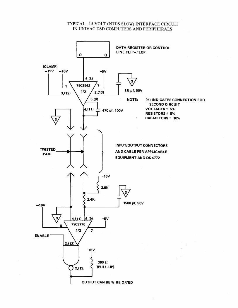
TYPICAL -15 VOLT (NTDS SLOW) INTERFACE CIRCUIT IN UNIVAC DSD COMPUTERS AND PERIPHERALS
Q
DATA REGISTER OR CONTROL LINE FLIP-FLOP
-15V -16V +5V
6,(8)
1
470 pt, 100V
1.5 tLt, 50V
NOTE: (#) INDICATES CONNECTION FOR SECOND CIRCUIT
VOLTAGES ± 5% RESISTORS ± 5% CAPACITORS ± 10%
TWISTED __ .... _---t ..
INPUT IOUTPUT CONN ECTORS
AND CABLE PER APPLICABLE
EQUIPMENT AND OS 4772 PAIR
-10V
8
ENABLE
-16V
3.9K
4 (11) _ 6,(9) +5V
+5V
390n (PULL-UP)
1500 pt, 50V
OUTPUT CAN BE WIRE OR'ED

SI=E~Y ~>= UNIVAC DEFENSE SYSTEMS ST. PAUL, MINNESOTA 55165
PX 34948
10-72