
Mil-Spec Connectors Design Guide - turck.us · Mil-Spec Connectors Originally, connectors that met...
80
Your Global Automation Partner Mil-Spec Connectors Design Guide
Transcript of Mil-Spec Connectors Design Guide - turck.us · Mil-Spec Connectors Originally, connectors that met...

Your Global Automation Partner
Mil-Spec Connectors Design Guide


A Global Leader in Industrial AutomationTurck’s sensors, connectivity, and fieldbus technology products are built to be
the best. As one of the most prominent sensor manufacturers in the world, we
even back our sensors with a lifetime warranty. Turck works by bringing rugged
engineering solutions to your industrial automation applications.
85,000+ 50+SOLUTIONS YEARS OF INNOVATION
EXTENSIVE WARRANTY
SUPPORT &DEDICATED SERVICE
RESPOND and SOLVE ov
er 1,200 inquiries per day
BUT LOCAL...GLOBAL
representations worldwide60
28 GLOBAL SUBSIDIARIESUSA
Strategically placed manufacturing facilities in the
with
4,000+APPLICATION EXPERTS
Developed innovative connectivity
solutions in response to our sensor customer needs
environments lead to I/O solutions
Pioneer in non-contact
sensing technology
Recognized need and advanced knowledge of harsh duty
2,000+EXPERIENCED SALES REPRESENTATIVES
4

TESTED
TURCK
TRUSTED
Contents06 Mil-Spec Connectors
07 The Turck Solution
08 Threaded
22 Bayonet
32 Reverse Bayonet
48 Bulk Cable
74 Glossary
76 Warranty Terms
and Conditions
5

Mil-Spec ConnectorsOriginally, connectors that met military specifications—also known as Mil-Spec
connectors—were created to ensure they met the toughest of requirements.
It was quickly realized that these strict Mil-Spec standards produced products
that are an ideal fit for rugged applications in areas such as automotive, mobile
equipment, and oil and gas applications among many more. Connectors that
meet the Mil-Spec requirements provide a robust, versatile solution for all
applications, even in harsh environments.
Dirt TempWater Wind Snow Vibration Impact
The Turck Solution
What Makes Turck Work?
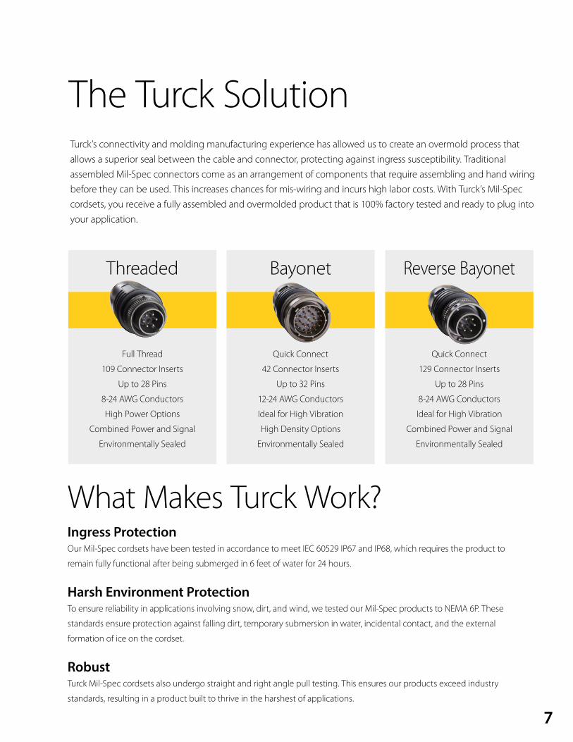
Turck’s connectivity and molding manufacturing experience has allowed us to create an overmold process that allows a superior seal between the cable and connector, protecting against ingress susceptibility. Traditional assembled Mil-Spec connectors come as an arrangement of components that require assembling and hand wiring before they can be used. This increases chances for mis-wiring and incurs high labor costs. With Turck’s Mil-Spec cordsets, you receive a fully assembled and overmolded product that is 100% factory tested and ready to plug into your application.
Full Thread
109 Connector Inserts
Up to 28 Pins
8-24 AWG Conductors
High Power Options
Combined Power and Signal
Environmentally Sealed
Quick Connect
42 Connector Inserts
Up to 32 Pins
12-24 AWG Conductors
Ideal for High Vibration
High Density Options
Environmentally Sealed
Quick Connect
129 Connector Inserts
Up to 28 Pins
8-24 AWG Conductors
Ideal for High Vibration
Combined Power and Signal
Environmentally Sealed
Ingress ProtectionOur Mil-Spec cordsets have been tested in accordance to meet IEC 60529 IP67 and IP68, which requires the product to
remain fully functional after being submerged in 6 feet of water for 24 hours.
Harsh Environment ProtectionTo ensure reliability in applications involving snow, dirt, and wind, we tested our Mil-Spec products to NEMA 6P. These
standards ensure protection against falling dirt, temporary submersion in water, incidental contact, and the external
formation of ice on the cordset.
RobustTurck Mil-Spec cordsets also undergo straight and right angle pull testing. This ensures our products exceed industry
standards, resulting in a product built to thrive in the harshest of applications.
Threaded Bayonet Reverse Bayonet
7

ThreadedTurck’s overmolded MIL-DTL-5015 threaded style connectors offer a fully threaded, tight connection that is ideal for
commercial applications. These connectors are available in a variety of shell sizes, number of contacts and layouts.
Overmolded Mil-Spec connectors provide a reduction in labor over traditional field-assembled connectors and
diminish the risk of mis-wiring by providing a complete overmolded cordset assembly, allowing you to decrease
downtime and save money. Turck’s overmold design technology provides the flexibility to seal the connectors to
a wide variety of different cable types. The threaded style connector is an ideal option for industrial applications,
including robotics, machine tools and welding. Variations in contact layouts allow for just power, just signal or a
mix of both contact types.
Applications:
• Conveyors
• Ships
• Trucks
• Trailers
• Encoders and other instrumentation
• Industrial machinery
• Factory automation
• Communications systems
8

Variety of cable options available
Fully threaded for tight seal
Meets NEMA 1, 3, 4, 6P
and IEC IP67, IP68 rated
Shell sizes 8-24
Provides more options for
power applications
Eyelet for closure cap lanyard
9
Mil-Spec Threaded
10
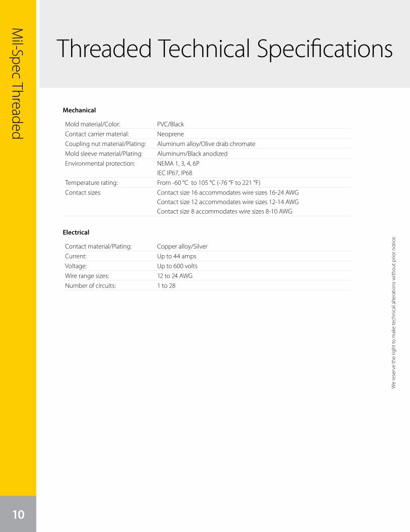
Threaded Technical Specifications
Mechanical
Electrical
Mold material/Color: PVC/BlackContact carrier material: NeopreneCoupling nut material/Plating: Aluminum alloy/Olive drab chromateMold sleeve material/Plating: Aluminum/Black anodizedEnvironmental protection: NEMA 1, 3, 4, 6P
IEC IP67, IP68Temperature rating: From -60 °C to 105 °C (-76 °F to 221 °F)Contact sizes: Contact size 16 accommodates wire sizes 16-24 AWG
Contact size 12 accommodates wire sizes 12-14 AWGContact size 8 accommodates wire sizes 8-10 AWG
Contact material/Plating: Copper alloy/SilverCurrent: Up to 44 ampsVoltage: Up to 600 voltsWire range sizes: 12 to 24 AWGNumber of circuits: 1 to 28
We
rese
rve
the
right
to m
ake
tech
nica
l alte
ratio
ns w
ithou
t prio
r not
ice.
We
rese
rve
the
right
to m
ake
tech
nica
l alte
ratio
ns w
ithou
t prio
r not
ice.
Mil-Spec Threaded
11For more information call Turck at 1-800-987-6543 or visit our website at www.turck.us
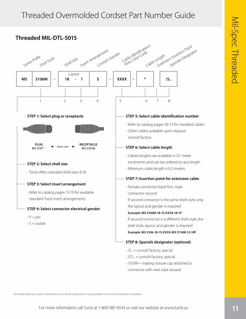
Threaded Overmolded Cordset Part Number Guide
STEP 1: Select plug or receptacle
STEP 2: Select shell size
- Turck offers standard shell sizes 8-24
STEP 3: Select insert arrangement
- Refer to catalog pages 13-19 for available
standard Turck insert arrangements
STEP 4: Select connector electrical gender
- P = pin
- S = socket
STEP 5: Select cable identification number
- Refer to catalog pages 50-73 for standard cables
- Other cables available upon request;
consult factory
STEP 6: Select cable length
- Cables lengths are available in 0.1 meter
increments and can be ordered to any length
- Minimum cable length is 0.2 meters
STEP 7: Insertion point for extension cable
- Female connector listed first, male
connector second
- If second connector is the same shell style, only
the layout and gender is required
Example: MS 3106M-18-1S-XXXX-18-1P
- If second connector is a different shell style, the
shell style, layout, and gender is required
Example: MS 3106-18-1S-XXXX-MS 3116M-12-10P
STEP 8: Specials designator (optional)
- /S.. = consult factory, special
- /CS.. = consult factory, special
- /S1599 = mating closure cap attached to
connector with wire rope lanyard
Series Prefix
1 2 3 4 5 6 7 8
Shell Style
Shell Size
Insert Arrangement
Contact Gender
Cable Identification/
Wire Color Code
Cable Length
MS 3106M - 18 - 1 S - XXXX - * /S..
Threaded MIL-DTL-5015
PLUGMS 3106M Mates with
RECEPTACLEMS 3101M
Layout
Specials Designator
Extension Insertion Point
Part Number Keys are to assist in identification only. Not all configurations may be available. Consult factory for product availability.
Mil-Spec Threaded
12
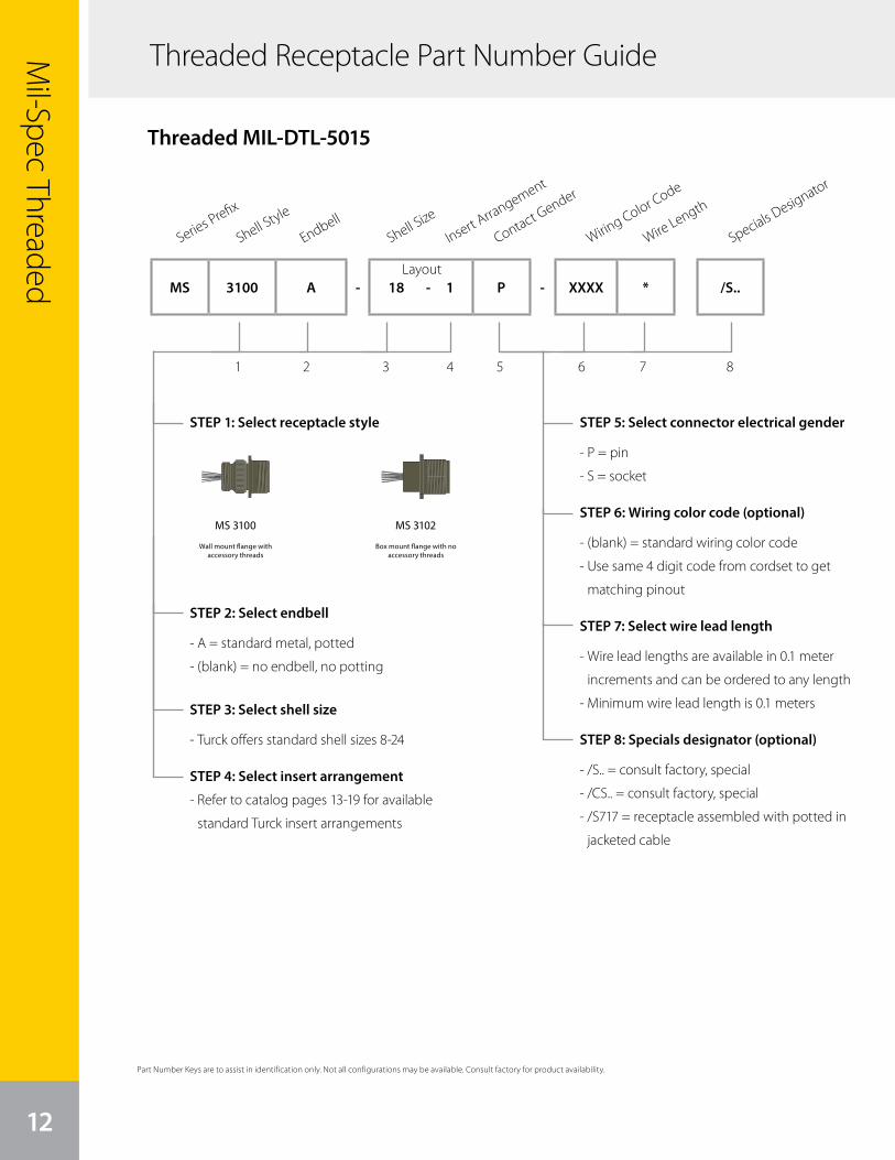
Threaded Receptacle Part Number Guide
STEP 1: Select receptacle style
STEP 2: Select endbell
- A = standard metal, potted
- (blank) = no endbell, no potting
STEP 3: Select shell size
- Turck offers standard shell sizes 8-24
STEP 4: Select insert arrangement
- Refer to catalog pages 13-19 for available
standard Turck insert arrangements
STEP 5: Select connector electrical gender
- P = pin
- S = socket
STEP 6: Wiring color code (optional)
- (blank) = standard wiring color code
- Use same 4 digit code from cordset to get
matching pinout
STEP 7: Select wire lead length
- Wire lead lengths are available in 0.1 meter
increments and can be ordered to any length
- Minimum wire lead length is 0.1 meters
STEP 8: Specials designator (optional)
- /S.. = consult factory, special
- /CS.. = consult factory, special
- /S717 = receptacle assembled with potted in
jacketed cable
Series Prefix
1 2 3 4 5 6 7 8
Shell Style
EndbellShell Size
Insert Arrangement
Contact Gender
Wire Length
Wiring Color Code
Specials Designator
MS 3100 A - 18 - 1 P - XXXX * /S..
Threaded MIL-DTL-5015
Layout
MS 3100
Wall mount flange with accessory threads
Box mount flange with no accessory threads
MS 3102
Part Number Keys are to assist in identification only. Not all configurations may be available. Consult factory for product availability.
We reserve the right to m
ake technical alterations without prior notice.
Specials Designator
Mil-Spec Threaded
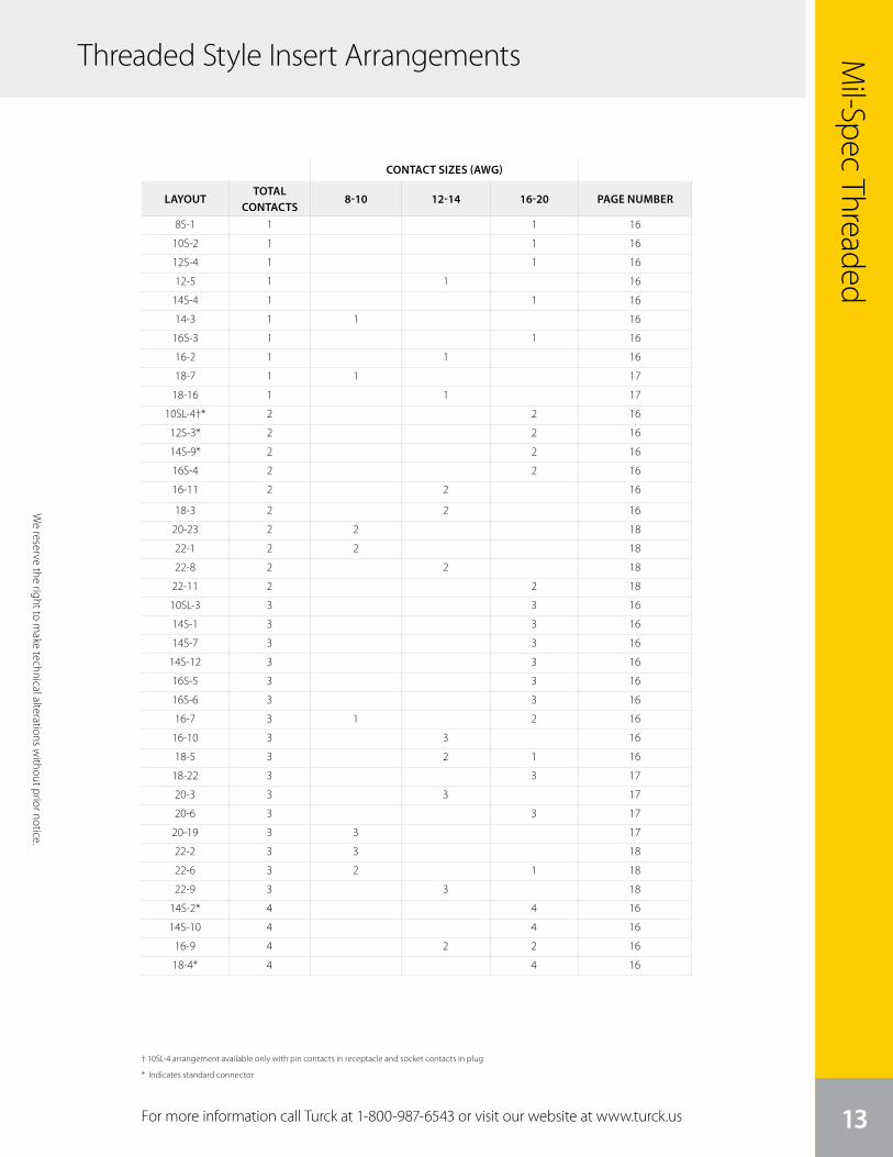
13For more information call Turck at 1-800-987-6543 or visit our website at www.turck.us
† 10SL-4 arrangement available only with pin contacts in receptacle and socket contacts in plug
* Indicates standard connector
We reserve the right to m
ake technical alterations without prior notice.
8S-1 1 1 16
10S-2 1 1 16
12S-4 1 1 16
12-5 1 1 16
14S-4 1 1 16
14-3 1 1 16
16S-3 1 1 16
16-2 1 1 16
18-7 1 1 17
18-16 1 1 17
10SL-4†* 2 2 16
12S-3* 2 2 16
14S-9* 2 2 16
16S-4 2 2 16
16-11 2 2 16
18-3 2 2 16
20-23 2 2 18
22-1 2 2 18
22-8 2 2 18
22-11 2 2 18
10SL-3 3 3 16
14S-1 3 3 16
14S-7 3 3 16
14S-12 3 3 16
16S-5 3 3 16
16S-6 3 3 16
16-7 3 1 2 16
16-10 3 3 16
18-5 3 2 1 16
18-22 3 3 17
20-3 3 3 17
20-6 3 3 17
20-19 3 3 17
22-2 3 3 18
22-6 3 2 1 18
22-9 3 3 18
14S-2* 4 4 16
14S-10 4 4 16
16-9 4 2 2 16
18-4* 4 4 16
CONTACT SIZES (AWG)
LAYOUTTOTAL
CONTACTS8-10 12-14 16-20 PAGE NUMBER
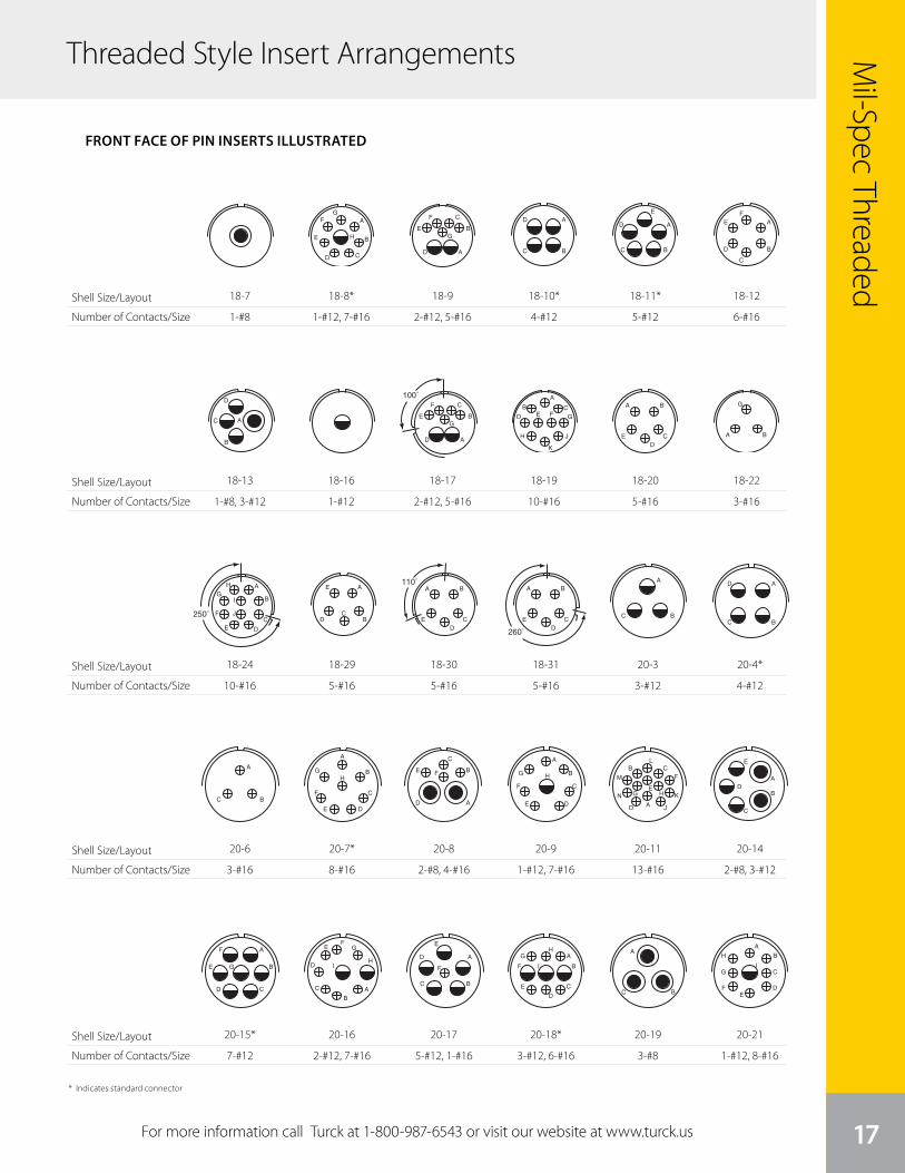
Threaded Style Insert Arrangements
14
Mil-Spec Threaded
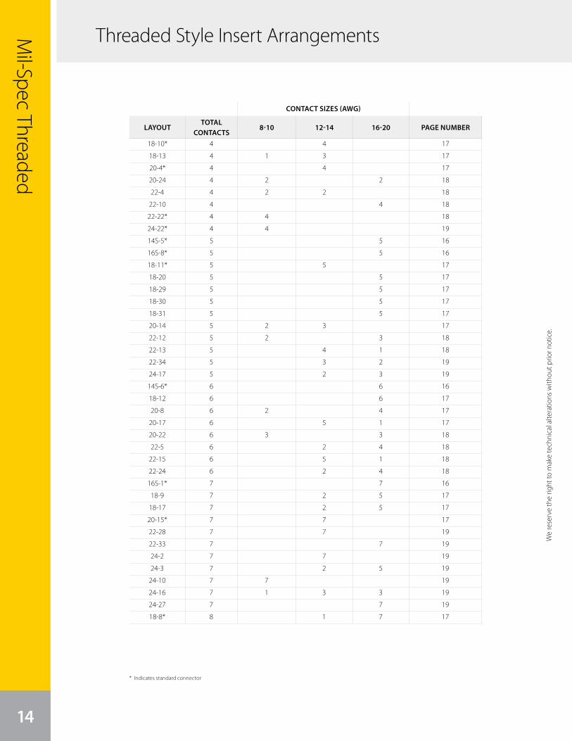
* Indicates standard connector
We
rese
rve
the
right
to m
ake
tech
nica
l alte
ratio
ns w
ithou
t prio
r not
ice.
CONTACT SIZES (AWG)
LAYOUTTOTAL
CONTACTS8-10 12-14 16-20 PAGE NUMBER
18-10* 4 4 17
18-13 4 1 3 17
20-4* 4 4 17
20-24 4 2 2 18
22-4 4 2 2 18
22-10 4 4 18
22-22* 4 4 18
24-22* 4 4 19
14S-5* 5 5 16
16S-8* 5 5 16
18-11* 5 5 17
18-20 5 5 17
18-29 5 5 17
18-30 5 5 17
18-31 5 5 17
20-14 5 2 3 17
22-12 5 2 3 18
22-13 5 4 1 18
22-34 5 3 2 19
24-17 5 2 3 19
14S-6* 6 6 16
18-12 6 6 17
20-8 6 2 4 17
20-17 6 5 1 17
20-22 6 3 3 18
22-5 6 2 4 18
22-15 6 5 1 18
22-24 6 2 4 18
16S-1* 7 7 16
18-9 7 2 5 17
18-17 7 2 5 17
20-15* 7 7 17
22-28 7 7 19
22-33 7 7 19
24-2 7 7 19
24-3 7 2 5 19
24-10 7 7 19
24-16 7 1 3 3 19
24-27 7 7 19
18-8* 8 1 7 17
Threaded Style Insert Arrangements
We reserve the right to m
ake technical alterations without prior notice.
We
rese
rve
the
right
to m
ake
tech
nica
l alte
ratio
ns w
ithou
t prio
r not
ice.
15
Mil-Spec Threaded
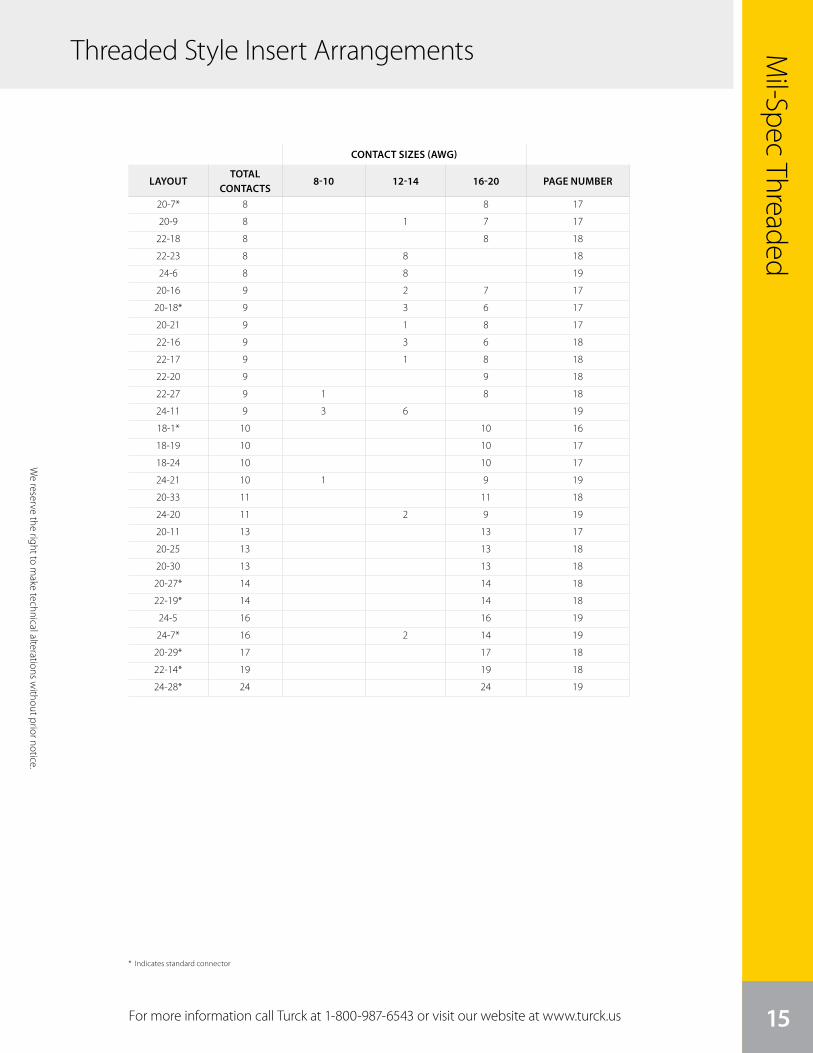
For more information call Turck at 1-800-987-6543 or visit our website at www.turck.us
We reserve the right to m
ake technical alterations without prior notice.
CONTACT SIZES (AWG)
LAYOUTTOTAL
CONTACTS8-10 12-14 16-20 PAGE NUMBER
* Indicates standard connector
20-7* 8 8 17
20-9 8 1 7 17
22-18 8 8 18
22-23 8 8 18
24-6 8 8 19
20-16 9 2 7 17
20-18* 9 3 6 17
20-21 9 1 8 17
22-16 9 3 6 18
22-17 9 1 8 18
22-20 9 9 18
22-27 9 1 8 18
24-11 9 3 6 19
18-1* 10 10 16
18-19 10 10 17
18-24 10 10 17
24-21 10 1 9 19
20-33 11 11 18
24-20 11 2 9 19
20-11 13 13 17
20-25 13 13 18
20-30 13 13 18
20-27* 14 14 18
22-19* 14 14 18
24-5 16 16 19
24-7* 16 2 14 19
20-29* 17 17 18
22-14* 19 19 18
24-28* 24 24 19
Threaded Style Insert Arrangements
Shell Size/Layout
Number of Contacts/Size
Shell Size/Layout
Number of Contacts/Size
Shell Size/Layout
Number of Contacts/Size
Shell Size/Layout
Number of Contacts/Size
26
front face of pin insert or rear face of socket insert illustrated
MS/Standardcontact arrangements
Insert Arrangement 8S-1 10S-2 10SL-3 10SL-4 12S-3 12S-4 12-5
Service Rating A A A A A D D
Number of Contacts 1 1 3 2 2 1 1
Contact Size 16 16 16 16 16 16 12
Insert Arrangement 14S-1 14S-2 14S-4 14S-5 14S-6 14S-7 14S-9
Service Rating A Inst. D Inst. Inst. A A
Number of Contacts 3 4 1 5 6 3 2
Contact Size 16 16 16 16 16 16 16
Insert Arrangement 14S-10 14S-12 14-3 16S-1 16S-3 16S-4
Service Rating Inst. A A A B D
Number of Contacts 4 3 1 7 1 2
Contact Size 16 16 8 16 16 16
Insert Arrangement 16S-5 16S-6 16S-8 16-2 16-7 16-9
Service Rating A A A E A A
Number of Contacts 3 3 5 1 1 2 2 2
Contact Size 16 16 16 12 8 16 12 16
CONTACT LEGEND 16 12 8 4 0
Front ofSocket Insert
Front ofSocket Insert
100° Rotationof 14S-2
100° Rotationof 14S-7
ABC
AB B A
A
BC
DA
B
C
D
E F A
B
CD
E A
B
C
AB
100˚A
BC
D
100˚
A
B
C
A
B
CD
E
F
G
AB
A
BC
A
B
C A
BC
D
E A B
C
A
B
C
D
A
B
C
8S-1
1-#16
26
front face of pin insert or rear face of socket insert illustrated
MS/Standardcontact arrangements
Insert Arrangement 8S-1 10S-2 10SL-3 10SL-4 12S-3 12S-4 12-5
Service Rating A A A A A D D
Number of Contacts 1 1 3 2 2 1 1
Contact Size 16 16 16 16 16 16 12
Insert Arrangement 14S-1 14S-2 14S-4 14S-5 14S-6 14S-7 14S-9
Service Rating A Inst. D Inst. Inst. A A
Number of Contacts 3 4 1 5 6 3 2
Contact Size 16 16 16 16 16 16 16
Insert Arrangement 14S-10 14S-12 14-3 16S-1 16S-3 16S-4
Service Rating Inst. A A A B D
Number of Contacts 4 3 1 7 1 2
Contact Size 16 16 8 16 16 16
Insert Arrangement 16S-5 16S-6 16S-8 16-2 16-7 16-9
Service Rating A A A E A A
Number of Contacts 3 3 5 1 1 2 2 2
Contact Size 16 16 16 12 8 16 12 16
CONTACT LEGEND 16 12 8 4 0
Front ofSocket Insert
Front ofSocket Insert
100° Rotationof 14S-2
100° Rotationof 14S-7
ABC
AB B A
A
BC
DA
B
C
D
E F A
B
CD
E A
B
C
AB
100˚A
BC
D
100˚
A
B
C
A
B
CD
E
F
G
AB
A
BC
A
B
C A
BC
D
E A B
C
A
B
C
D
A
B
C
14S-1
3-#16
26
front face of pin insert or rear face of socket insert illustrated
MS/Standardcontact arrangements
Insert Arrangement 8S-1 10S-2 10SL-3 10SL-4 12S-3 12S-4 12-5
Service Rating A A A A A D D
Number of Contacts 1 1 3 2 2 1 1
Contact Size 16 16 16 16 16 16 12
Insert Arrangement 14S-1 14S-2 14S-4 14S-5 14S-6 14S-7 14S-9
Service Rating A Inst. D Inst. Inst. A A
Number of Contacts 3 4 1 5 6 3 2
Contact Size 16 16 16 16 16 16 16
Insert Arrangement 14S-10 14S-12 14-3 16S-1 16S-3 16S-4
Service Rating Inst. A A A B D
Number of Contacts 4 3 1 7 1 2
Contact Size 16 16 8 16 16 16
Insert Arrangement 16S-5 16S-6 16S-8 16-2 16-7 16-9
Service Rating A A A E A A
Number of Contacts 3 3 5 1 1 2 2 2
Contact Size 16 16 16 12 8 16 12 16
CONTACT LEGEND 16 12 8 4 0
Front ofSocket Insert
Front ofSocket Insert
100° Rotationof 14S-2
100° Rotationof 14S-7
ABC
AB B A
A
BC
DA
B
C
D
E F A
B
CD
E A
B
C
AB
100˚A
BC
D
100˚
A
B
C
A
B
CD
E
F
G
AB
A
BC
A
B
C A
BC
D
E A B
C
A
B
C
D
A
B
C
14S-10
4-#16
26
front face of pin insert or rear face of socket insert illustrated
MS/Standardcontact arrangements
Insert Arrangement 8S-1 10S-2 10SL-3 10SL-4 12S-3 12S-4 12-5
Service Rating A A A A A D D
Number of Contacts 1 1 3 2 2 1 1
Contact Size 16 16 16 16 16 16 12
Insert Arrangement 14S-1 14S-2 14S-4 14S-5 14S-6 14S-7 14S-9
Service Rating A Inst. D Inst. Inst. A A
Number of Contacts 3 4 1 5 6 3 2
Contact Size 16 16 16 16 16 16 16
Insert Arrangement 14S-10 14S-12 14-3 16S-1 16S-3 16S-4
Service Rating Inst. A A A B D
Number of Contacts 4 3 1 7 1 2
Contact Size 16 16 8 16 16 16
Insert Arrangement 16S-5 16S-6 16S-8 16-2 16-7 16-9
Service Rating A A A E A A
Number of Contacts 3 3 5 1 1 2 2 2
Contact Size 16 16 16 12 8 16 12 16
CONTACT LEGEND 16 12 8 4 0
Front ofSocket Insert
Front ofSocket Insert
100° Rotationof 14S-2
100° Rotationof 14S-7
ABC
AB B A
A
BC
DA
B
C
D
E F A
B
CD
E A
B
C
AB
100˚A
BC
D
100˚
A
B
C
A
B
CD
E
F
G
AB
A
BC
A
B
C A
BC
D
E A B
C
A
B
C
D
A
B
C
16S-5
3-#16
26
front face of pin insert or rear face of socket insert illustrated
MS/Standardcontact arrangements
Insert Arrangement 8S-1 10S-2 10SL-3 10SL-4 12S-3 12S-4 12-5
Service Rating A A A A A D D
Number of Contacts 1 1 3 2 2 1 1
Contact Size 16 16 16 16 16 16 12
Insert Arrangement 14S-1 14S-2 14S-4 14S-5 14S-6 14S-7 14S-9
Service Rating A Inst. D Inst. Inst. A A
Number of Contacts 3 4 1 5 6 3 2
Contact Size 16 16 16 16 16 16 16
Insert Arrangement 14S-10 14S-12 14-3 16S-1 16S-3 16S-4
Service Rating Inst. A A A B D
Number of Contacts 4 3 1 7 1 2
Contact Size 16 16 8 16 16 16
Insert Arrangement 16S-5 16S-6 16S-8 16-2 16-7 16-9
Service Rating A A A E A A
Number of Contacts 3 3 5 1 1 2 2 2
Contact Size 16 16 16 12 8 16 12 16
CONTACT LEGEND 16 12 8 4 0
Front ofSocket Insert
Front ofSocket Insert
100° Rotationof 14S-2
100° Rotationof 14S-7
ABC
AB B A
A
BC
DA
B
C
D
E F A
B
CD
E A
B
C
AB
100˚A
BC
D
100˚
A
B
C
A
B
CD
E
F
G
AB
A
BC
A
B
C A
BC
D
E A B
C
A
B
C
D
A
B
C
14S-12
3-#16
26
front face of pin insert or rear face of socket insert illustrated
MS/Standardcontact arrangements
Insert Arrangement 8S-1 10S-2 10SL-3 10SL-4 12S-3 12S-4 12-5
Service Rating A A A A A D D
Number of Contacts 1 1 3 2 2 1 1
Contact Size 16 16 16 16 16 16 12
Insert Arrangement 14S-1 14S-2 14S-4 14S-5 14S-6 14S-7 14S-9
Service Rating A Inst. D Inst. Inst. A A
Number of Contacts 3 4 1 5 6 3 2
Contact Size 16 16 16 16 16 16 16
Insert Arrangement 14S-10 14S-12 14-3 16S-1 16S-3 16S-4
Service Rating Inst. A A A B D
Number of Contacts 4 3 1 7 1 2
Contact Size 16 16 8 16 16 16
Insert Arrangement 16S-5 16S-6 16S-8 16-2 16-7 16-9
Service Rating A A A E A A
Number of Contacts 3 3 5 1 1 2 2 2
Contact Size 16 16 16 12 8 16 12 16
CONTACT LEGEND 16 12 8 4 0
Front ofSocket Insert
Front ofSocket Insert
100° Rotationof 14S-2
100° Rotationof 14S-7
ABC
AB B A
A
BC
DA
B
C
D
E F A
B
CD
E A
B
C
AB
100˚A
BC
D
100˚
A
B
C
A
B
CD
E
F
G
AB
A
BC
A
B
C A
BC
D
E A B
C
A
B
C
D
A
B
C
16S-6
3-#16
26
front face of pin insert or rear face of socket insert illustrated
MS/Standardcontact arrangements
Insert Arrangement 8S-1 10S-2 10SL-3 10SL-4 12S-3 12S-4 12-5
Service Rating A A A A A D D
Number of Contacts 1 1 3 2 2 1 1
Contact Size 16 16 16 16 16 16 12
Insert Arrangement 14S-1 14S-2 14S-4 14S-5 14S-6 14S-7 14S-9
Service Rating A Inst. D Inst. Inst. A A
Number of Contacts 3 4 1 5 6 3 2
Contact Size 16 16 16 16 16 16 16
Insert Arrangement 14S-10 14S-12 14-3 16S-1 16S-3 16S-4
Service Rating Inst. A A A B D
Number of Contacts 4 3 1 7 1 2
Contact Size 16 16 8 16 16 16
Insert Arrangement 16S-5 16S-6 16S-8 16-2 16-7 16-9
Service Rating A A A E A A
Number of Contacts 3 3 5 1 1 2 2 2
Contact Size 16 16 16 12 8 16 12 16
CONTACT LEGEND 16 12 8 4 0
Front ofSocket Insert
Front ofSocket Insert
100° Rotationof 14S-2
100° Rotationof 14S-7
ABC
AB B A
A
BC
DA
B
C
D
E F A
B
CD
E A
B
C
AB
100˚A
BC
D
100˚
A
B
C
A
B
CD
E
F
G
AB
A
BC
A
B
C A
BC
D
E A B
C
A
B
C
D
A
B
C
16S-8*
5-#16
26
front face of pin insert or rear face of socket insert illustrated
MS/Standardcontact arrangements
Insert Arrangement 8S-1 10S-2 10SL-3 10SL-4 12S-3 12S-4 12-5
Service Rating A A A A A D D
Number of Contacts 1 1 3 2 2 1 1
Contact Size 16 16 16 16 16 16 12
Insert Arrangement 14S-1 14S-2 14S-4 14S-5 14S-6 14S-7 14S-9
Service Rating A Inst. D Inst. Inst. A A
Number of Contacts 3 4 1 5 6 3 2
Contact Size 16 16 16 16 16 16 16
Insert Arrangement 14S-10 14S-12 14-3 16S-1 16S-3 16S-4
Service Rating Inst. A A A B D
Number of Contacts 4 3 1 7 1 2
Contact Size 16 16 8 16 16 16
Insert Arrangement 16S-5 16S-6 16S-8 16-2 16-7 16-9
Service Rating A A A E A A
Number of Contacts 3 3 5 1 1 2 2 2
Contact Size 16 16 16 12 8 16 12 16
CONTACT LEGEND 16 12 8 4 0
Front ofSocket Insert
Front ofSocket Insert
100° Rotationof 14S-2
100° Rotationof 14S-7
ABC
AB B A
A
BC
DA
B
C
D
E F A
B
CD
E A
B
C
AB
100˚A
BC
D
100˚
A
B
C
A
B
CD
E
F
G
AB
A
BC
A
B
C A
BC
D
E A B
C
A
B
C
D
A
B
C
16-2
1-#12
26
front face of pin insert or rear face of socket insert illustrated
MS/Standardcontact arrangements
Insert Arrangement 8S-1 10S-2 10SL-3 10SL-4 12S-3 12S-4 12-5
Service Rating A A A A A D D
Number of Contacts 1 1 3 2 2 1 1
Contact Size 16 16 16 16 16 16 12
Insert Arrangement 14S-1 14S-2 14S-4 14S-5 14S-6 14S-7 14S-9
Service Rating A Inst. D Inst. Inst. A A
Number of Contacts 3 4 1 5 6 3 2
Contact Size 16 16 16 16 16 16 16
Insert Arrangement 14S-10 14S-12 14-3 16S-1 16S-3 16S-4
Service Rating Inst. A A A B D
Number of Contacts 4 3 1 7 1 2
Contact Size 16 16 8 16 16 16
Insert Arrangement 16S-5 16S-6 16S-8 16-2 16-7 16-9
Service Rating A A A E A A
Number of Contacts 3 3 5 1 1 2 2 2
Contact Size 16 16 16 12 8 16 12 16
CONTACT LEGEND 16 12 8 4 0
Front ofSocket Insert
Front ofSocket Insert
100° Rotationof 14S-2
100° Rotationof 14S-7
ABC
AB B A
A
BC
DA
B
C
D
E F A
B
CD
E A
B
C
AB
100˚A
BC
D
100˚
A
B
C
A
B
CD
E
F
G
AB
A
BC
A
B
C A
BC
D
E A B
C
A
B
C
D
A
B
C
16-7
1-#8, 2-#16
26
front face of pin insert or rear face of socket insert illustrated
MS/Standardcontact arrangements
Insert Arrangement 8S-1 10S-2 10SL-3 10SL-4 12S-3 12S-4 12-5
Service Rating A A A A A D D
Number of Contacts 1 1 3 2 2 1 1
Contact Size 16 16 16 16 16 16 12
Insert Arrangement 14S-1 14S-2 14S-4 14S-5 14S-6 14S-7 14S-9
Service Rating A Inst. D Inst. Inst. A A
Number of Contacts 3 4 1 5 6 3 2
Contact Size 16 16 16 16 16 16 16
Insert Arrangement 14S-10 14S-12 14-3 16S-1 16S-3 16S-4
Service Rating Inst. A A A B D
Number of Contacts 4 3 1 7 1 2
Contact Size 16 16 8 16 16 16
Insert Arrangement 16S-5 16S-6 16S-8 16-2 16-7 16-9
Service Rating A A A E A A
Number of Contacts 3 3 5 1 1 2 2 2
Contact Size 16 16 16 12 8 16 12 16
CONTACT LEGEND 16 12 8 4 0
Front ofSocket Insert
Front ofSocket Insert
100° Rotationof 14S-2
100° Rotationof 14S-7
ABC
AB B A
A
BC
DA
B
C
D
E F A
B
CD
E A
B
C
AB
100˚A
BC
D
100˚
A
B
C
A
B
CD
E
F
G
AB
A
BC
A
B
C A
BC
D
E A B
C
A
B
C
D
A
B
C
16-9
2-#12, 2-#16
26
front face of pin insert or rear face of socket insert illustrated
MS/Standardcontact arrangements
Insert Arrangement 8S-1 10S-2 10SL-3 10SL-4 12S-3 12S-4 12-5
Service Rating A A A A A D D
Number of Contacts 1 1 3 2 2 1 1
Contact Size 16 16 16 16 16 16 12
Insert Arrangement 14S-1 14S-2 14S-4 14S-5 14S-6 14S-7 14S-9
Service Rating A Inst. D Inst. Inst. A A
Number of Contacts 3 4 1 5 6 3 2
Contact Size 16 16 16 16 16 16 16
Insert Arrangement 14S-10 14S-12 14-3 16S-1 16S-3 16S-4
Service Rating Inst. A A A B D
Number of Contacts 4 3 1 7 1 2
Contact Size 16 16 8 16 16 16
Insert Arrangement 16S-5 16S-6 16S-8 16-2 16-7 16-9
Service Rating A A A E A A
Number of Contacts 3 3 5 1 1 2 2 2
Contact Size 16 16 16 12 8 16 12 16
CONTACT LEGEND 16 12 8 4 0
Front ofSocket Insert
Front ofSocket Insert
100° Rotationof 14S-2
100° Rotationof 14S-7
ABC
AB B A
A
BC
DA
B
C
D
E F A
B
CD
E A
B
C
AB
100˚A
BC
D
100˚
A
B
C
A
B
CD
E
F
G
AB
A
BC
A
B
C A
BC
D
E A B
C
A
B
C
D
A
B
C
14-3
1-#8
26
front face of pin insert or rear face of socket insert illustrated
MS/Standardcontact arrangements
Insert Arrangement 8S-1 10S-2 10SL-3 10SL-4 12S-3 12S-4 12-5
Service Rating A A A A A D D
Number of Contacts 1 1 3 2 2 1 1
Contact Size 16 16 16 16 16 16 12
Insert Arrangement 14S-1 14S-2 14S-4 14S-5 14S-6 14S-7 14S-9
Service Rating A Inst. D Inst. Inst. A A
Number of Contacts 3 4 1 5 6 3 2
Contact Size 16 16 16 16 16 16 16
Insert Arrangement 14S-10 14S-12 14-3 16S-1 16S-3 16S-4
Service Rating Inst. A A A B D
Number of Contacts 4 3 1 7 1 2
Contact Size 16 16 8 16 16 16
Insert Arrangement 16S-5 16S-6 16S-8 16-2 16-7 16-9
Service Rating A A A E A A
Number of Contacts 3 3 5 1 1 2 2 2
Contact Size 16 16 16 12 8 16 12 16
CONTACT LEGEND 16 12 8 4 0
Front ofSocket Insert
Front ofSocket Insert
100° Rotationof 14S-2
100° Rotationof 14S-7
ABC
AB B A
A
BC
DA
B
C
D
E F A
B
CD
E A
B
C
AB
100˚A
BC
D
100˚
A
B
C
A
B
CD
E
F
G
AB
A
BC
A
B
C A
BC
D
E A B
C
A
B
C
D
A
B
C
16S-1*
7-#16
26
front face of pin insert or rear face of socket insert illustrated
MS/Standardcontact arrangements
Insert Arrangement 8S-1 10S-2 10SL-3 10SL-4 12S-3 12S-4 12-5
Service Rating A A A A A D D
Number of Contacts 1 1 3 2 2 1 1
Contact Size 16 16 16 16 16 16 12
Insert Arrangement 14S-1 14S-2 14S-4 14S-5 14S-6 14S-7 14S-9
Service Rating A Inst. D Inst. Inst. A A
Number of Contacts 3 4 1 5 6 3 2
Contact Size 16 16 16 16 16 16 16
Insert Arrangement 14S-10 14S-12 14-3 16S-1 16S-3 16S-4
Service Rating Inst. A A A B D
Number of Contacts 4 3 1 7 1 2
Contact Size 16 16 8 16 16 16
Insert Arrangement 16S-5 16S-6 16S-8 16-2 16-7 16-9
Service Rating A A A E A A
Number of Contacts 3 3 5 1 1 2 2 2
Contact Size 16 16 16 12 8 16 12 16
CONTACT LEGEND 16 12 8 4 0
Front ofSocket Insert
Front ofSocket Insert
100° Rotationof 14S-2
100° Rotationof 14S-7
ABC
AB B A
A
BC
DA
B
C
D
E F A
B
CD
E A
B
C
AB
100˚A
BC
D
100˚
A
B
C
A
B
CD
E
F
G
AB
A
BC
A
B
C A
BC
D
E A B
C
A
B
C
D
A
B
C
16S-3
1-#16
26
front face of pin insert or rear face of socket insert illustrated
MS/Standardcontact arrangements
Insert Arrangement 8S-1 10S-2 10SL-3 10SL-4 12S-3 12S-4 12-5
Service Rating A A A A A D D
Number of Contacts 1 1 3 2 2 1 1
Contact Size 16 16 16 16 16 16 12
Insert Arrangement 14S-1 14S-2 14S-4 14S-5 14S-6 14S-7 14S-9
Service Rating A Inst. D Inst. Inst. A A
Number of Contacts 3 4 1 5 6 3 2
Contact Size 16 16 16 16 16 16 16
Insert Arrangement 14S-10 14S-12 14-3 16S-1 16S-3 16S-4
Service Rating Inst. A A A B D
Number of Contacts 4 3 1 7 1 2
Contact Size 16 16 8 16 16 16
Insert Arrangement 16S-5 16S-6 16S-8 16-2 16-7 16-9
Service Rating A A A E A A
Number of Contacts 3 3 5 1 1 2 2 2
Contact Size 16 16 16 12 8 16 12 16
CONTACT LEGEND 16 12 8 4 0
Front ofSocket Insert
Front ofSocket Insert
100° Rotationof 14S-2
100° Rotationof 14S-7
ABC
AB B A
A
BC
DA
B
C
D
E F A
B
CD
E A
B
C
AB
100˚A
BC
D
100˚
A
B
C
A
B
CD
E
F
G
AB
A
BC
A
B
C A
BC
D
E A B
C
A
B
C
D
A
B
C
16S-4
2-#16
26
front face of pin insert or rear face of socket insert illustrated
MS/Standardcontact arrangements
Insert Arrangement 8S-1 10S-2 10SL-3 10SL-4 12S-3 12S-4 12-5
Service Rating A A A A A D D
Number of Contacts 1 1 3 2 2 1 1
Contact Size 16 16 16 16 16 16 12
Insert Arrangement 14S-1 14S-2 14S-4 14S-5 14S-6 14S-7 14S-9
Service Rating A Inst. D Inst. Inst. A A
Number of Contacts 3 4 1 5 6 3 2
Contact Size 16 16 16 16 16 16 16
Insert Arrangement 14S-10 14S-12 14-3 16S-1 16S-3 16S-4
Service Rating Inst. A A A B D
Number of Contacts 4 3 1 7 1 2
Contact Size 16 16 8 16 16 16
Insert Arrangement 16S-5 16S-6 16S-8 16-2 16-7 16-9
Service Rating A A A E A A
Number of Contacts 3 3 5 1 1 2 2 2
Contact Size 16 16 16 12 8 16 12 16
CONTACT LEGEND 16 12 8 4 0
Front ofSocket Insert
Front ofSocket Insert
100° Rotationof 14S-2
100° Rotationof 14S-7
ABC
AB B A
A
BC
DA
B
C
D
E F A
B
CD
E A
B
C
AB
100˚A
BC
D
100˚
A
B
C
A
B
CD
E
F
G
AB
A
BC
A
B
C A
BC
D
E A B
C
A
B
C
D
A
B
C
10S-2
1-#16
26
front face of pin insert or rear face of socket insert illustrated
MS/Standardcontact arrangements
Insert Arrangement 8S-1 10S-2 10SL-3 10SL-4 12S-3 12S-4 12-5
Service Rating A A A A A D D
Number of Contacts 1 1 3 2 2 1 1
Contact Size 16 16 16 16 16 16 12
Insert Arrangement 14S-1 14S-2 14S-4 14S-5 14S-6 14S-7 14S-9
Service Rating A Inst. D Inst. Inst. A A
Number of Contacts 3 4 1 5 6 3 2
Contact Size 16 16 16 16 16 16 16
Insert Arrangement 14S-10 14S-12 14-3 16S-1 16S-3 16S-4
Service Rating Inst. A A A B D
Number of Contacts 4 3 1 7 1 2
Contact Size 16 16 8 16 16 16
Insert Arrangement 16S-5 16S-6 16S-8 16-2 16-7 16-9
Service Rating A A A E A A
Number of Contacts 3 3 5 1 1 2 2 2
Contact Size 16 16 16 12 8 16 12 16
CONTACT LEGEND 16 12 8 4 0
Front ofSocket Insert
Front ofSocket Insert
100° Rotationof 14S-2
100° Rotationof 14S-7
ABC
AB B A
A
BC
DA
B
C
D
E F A
B
CD
E A
B
C
AB
100˚A
BC
D
100˚
A
B
C
A
B
CD
E
F
G
AB
A
BC
A
B
C A
BC
D
E A B
C
A
B
C
D
A
B
C
14S-2*
4-#16
26
front face of pin insert or rear face of socket insert illustrated
MS/Standardcontact arrangements
Insert Arrangement 8S-1 10S-2 10SL-3 10SL-4 12S-3 12S-4 12-5
Service Rating A A A A A D D
Number of Contacts 1 1 3 2 2 1 1
Contact Size 16 16 16 16 16 16 12
Insert Arrangement 14S-1 14S-2 14S-4 14S-5 14S-6 14S-7 14S-9
Service Rating A Inst. D Inst. Inst. A A
Number of Contacts 3 4 1 5 6 3 2
Contact Size 16 16 16 16 16 16 16
Insert Arrangement 14S-10 14S-12 14-3 16S-1 16S-3 16S-4
Service Rating Inst. A A A B D
Number of Contacts 4 3 1 7 1 2
Contact Size 16 16 8 16 16 16
Insert Arrangement 16S-5 16S-6 16S-8 16-2 16-7 16-9
Service Rating A A A E A A
Number of Contacts 3 3 5 1 1 2 2 2
Contact Size 16 16 16 12 8 16 12 16
CONTACT LEGEND 16 12 8 4 0
Front ofSocket Insert
Front ofSocket Insert
100° Rotationof 14S-2
100° Rotationof 14S-7
ABC
AB B A
A
BC
DA
B
C
D
E F A
B
CD
E A
B
C
AB
100˚A
BC
D
100˚
A
B
C
A
B
CD
E
F
G
AB
A
BC
A
B
C A
BC
D
E A B
C
A
B
C
D
A
B
C
14S-4
1-#16
26
front face of pin insert or rear face of socket insert illustrated
MS/Standardcontact arrangements
Insert Arrangement 8S-1 10S-2 10SL-3 10SL-4 12S-3 12S-4 12-5
Service Rating A A A A A D D
Number of Contacts 1 1 3 2 2 1 1
Contact Size 16 16 16 16 16 16 12
Insert Arrangement 14S-1 14S-2 14S-4 14S-5 14S-6 14S-7 14S-9
Service Rating A Inst. D Inst. Inst. A A
Number of Contacts 3 4 1 5 6 3 2
Contact Size 16 16 16 16 16 16 16
Insert Arrangement 14S-10 14S-12 14-3 16S-1 16S-3 16S-4
Service Rating Inst. A A A B D
Number of Contacts 4 3 1 7 1 2
Contact Size 16 16 8 16 16 16
Insert Arrangement 16S-5 16S-6 16S-8 16-2 16-7 16-9
Service Rating A A A E A A
Number of Contacts 3 3 5 1 1 2 2 2
Contact Size 16 16 16 12 8 16 12 16
CONTACT LEGEND 16 12 8 4 0
Front ofSocket Insert
Front ofSocket Insert
100° Rotationof 14S-2
100° Rotationof 14S-7
ABC
AB B A
A
BC
DA
B
C
D
E F A
B
CD
E A
B
C
AB
100˚A
BC
D
100˚
A
B
C
A
B
CD
E
F
G
AB
A
BC
A
B
C A
BC
D
E A B
C
A
B
C
D
A
B
C
14S-5*
5-#16
26
front face of pin insert or rear face of socket insert illustrated
MS/Standardcontact arrangements
Insert Arrangement 8S-1 10S-2 10SL-3 10SL-4 12S-3 12S-4 12-5
Service Rating A A A A A D D
Number of Contacts 1 1 3 2 2 1 1
Contact Size 16 16 16 16 16 16 12
Insert Arrangement 14S-1 14S-2 14S-4 14S-5 14S-6 14S-7 14S-9
Service Rating A Inst. D Inst. Inst. A A
Number of Contacts 3 4 1 5 6 3 2
Contact Size 16 16 16 16 16 16 16
Insert Arrangement 14S-10 14S-12 14-3 16S-1 16S-3 16S-4
Service Rating Inst. A A A B D
Number of Contacts 4 3 1 7 1 2
Contact Size 16 16 8 16 16 16
Insert Arrangement 16S-5 16S-6 16S-8 16-2 16-7 16-9
Service Rating A A A E A A
Number of Contacts 3 3 5 1 1 2 2 2
Contact Size 16 16 16 12 8 16 12 16
CONTACT LEGEND 16 12 8 4 0
Front ofSocket Insert
Front ofSocket Insert
100° Rotationof 14S-2
100° Rotationof 14S-7
ABC
AB B A
A
BC
DA
B
C
D
E F A
B
CD
E A
B
C
AB
100˚A
BC
D
100˚
A
B
C
A
B
CD
E
F
G
AB
A
BC
A
B
C A
BC
D
E A B
C
A
B
C
D
A
B
C
14S-6*
6-#16
26
front face of pin insert or rear face of socket insert illustrated
MS/Standardcontact arrangements
Insert Arrangement 8S-1 10S-2 10SL-3 10SL-4 12S-3 12S-4 12-5
Service Rating A A A A A D D
Number of Contacts 1 1 3 2 2 1 1
Contact Size 16 16 16 16 16 16 12
Insert Arrangement 14S-1 14S-2 14S-4 14S-5 14S-6 14S-7 14S-9
Service Rating A Inst. D Inst. Inst. A A
Number of Contacts 3 4 1 5 6 3 2
Contact Size 16 16 16 16 16 16 16
Insert Arrangement 14S-10 14S-12 14-3 16S-1 16S-3 16S-4
Service Rating Inst. A A A B D
Number of Contacts 4 3 1 7 1 2
Contact Size 16 16 8 16 16 16
Insert Arrangement 16S-5 16S-6 16S-8 16-2 16-7 16-9
Service Rating A A A E A A
Number of Contacts 3 3 5 1 1 2 2 2
Contact Size 16 16 16 12 8 16 12 16
CONTACT LEGEND 16 12 8 4 0
Front ofSocket Insert
Front ofSocket Insert
100° Rotationof 14S-2
100° Rotationof 14S-7
ABC
AB B A
A
BC
DA
B
C
D
E F A
B
CD
E A
B
C
AB
100˚A
BC
D
100˚
A
B
C
A
B
CD
E
F
G
AB
A
BC
A
B
C A
BC
D
E A B
C
A
B
C
D
A
B
C
14S-7
3-#16
26
front face of pin insert or rear face of socket insert illustrated
MS/Standardcontact arrangements
Insert Arrangement 8S-1 10S-2 10SL-3 10SL-4 12S-3 12S-4 12-5
Service Rating A A A A A D D
Number of Contacts 1 1 3 2 2 1 1
Contact Size 16 16 16 16 16 16 12
Insert Arrangement 14S-1 14S-2 14S-4 14S-5 14S-6 14S-7 14S-9
Service Rating A Inst. D Inst. Inst. A A
Number of Contacts 3 4 1 5 6 3 2
Contact Size 16 16 16 16 16 16 16
Insert Arrangement 14S-10 14S-12 14-3 16S-1 16S-3 16S-4
Service Rating Inst. A A A B D
Number of Contacts 4 3 1 7 1 2
Contact Size 16 16 8 16 16 16
Insert Arrangement 16S-5 16S-6 16S-8 16-2 16-7 16-9
Service Rating A A A E A A
Number of Contacts 3 3 5 1 1 2 2 2
Contact Size 16 16 16 12 8 16 12 16
CONTACT LEGEND 16 12 8 4 0
Front ofSocket Insert
Front ofSocket Insert
100° Rotationof 14S-2
100° Rotationof 14S-7
ABC
AB B A
A
BC
DA
B
C
D
E F A
B
CD
E A
B
C
AB
100˚A
BC
D
100˚
A
B
C
A
B
CD
E
F
G
AB
A
BC
A
B
C A
BC
D
E A B
C
A
B
C
D
A
B
C
14S-9*
2-#16
26
front face of pin insert or rear face of socket insert illustrated
MS/Standardcontact arrangements
Insert Arrangement 8S-1 10S-2 10SL-3 10SL-4 12S-3 12S-4 12-5
Service Rating A A A A A D D
Number of Contacts 1 1 3 2 2 1 1
Contact Size 16 16 16 16 16 16 12
Insert Arrangement 14S-1 14S-2 14S-4 14S-5 14S-6 14S-7 14S-9
Service Rating A Inst. D Inst. Inst. A A
Number of Contacts 3 4 1 5 6 3 2
Contact Size 16 16 16 16 16 16 16
Insert Arrangement 14S-10 14S-12 14-3 16S-1 16S-3 16S-4
Service Rating Inst. A A A B D
Number of Contacts 4 3 1 7 1 2
Contact Size 16 16 8 16 16 16
Insert Arrangement 16S-5 16S-6 16S-8 16-2 16-7 16-9
Service Rating A A A E A A
Number of Contacts 3 3 5 1 1 2 2 2
Contact Size 16 16 16 12 8 16 12 16
CONTACT LEGEND 16 12 8 4 0
Front ofSocket Insert
Front ofSocket Insert
100° Rotationof 14S-2
100° Rotationof 14S-7
ABC
AB B A
A
BC
DA
B
C
D
E F A
B
CD
E A
B
C
AB
100˚A
BC
D
100˚
A
B
C
A
B
CD
E
F
G
AB
A
BC
A
B
C A
BC
D
E A B
C
A
B
C
D
A
B
C
10SL-3
3-#16
26
front face of pin insert or rear face of socket insert illustrated
MS/Standardcontact arrangements
Insert Arrangement 8S-1 10S-2 10SL-3 10SL-4 12S-3 12S-4 12-5
Service Rating A A A A A D D
Number of Contacts 1 1 3 2 2 1 1
Contact Size 16 16 16 16 16 16 12
Insert Arrangement 14S-1 14S-2 14S-4 14S-5 14S-6 14S-7 14S-9
Service Rating A Inst. D Inst. Inst. A A
Number of Contacts 3 4 1 5 6 3 2
Contact Size 16 16 16 16 16 16 16
Insert Arrangement 14S-10 14S-12 14-3 16S-1 16S-3 16S-4
Service Rating Inst. A A A B D
Number of Contacts 4 3 1 7 1 2
Contact Size 16 16 8 16 16 16
Insert Arrangement 16S-5 16S-6 16S-8 16-2 16-7 16-9
Service Rating A A A E A A
Number of Contacts 3 3 5 1 1 2 2 2
Contact Size 16 16 16 12 8 16 12 16
CONTACT LEGEND 16 12 8 4 0
Front ofSocket Insert
Front ofSocket Insert
100° Rotationof 14S-2
100° Rotationof 14S-7
ABC
AB B A
A
BC
DA
B
C
D
E F A
B
CD
E A
B
C
AB
100˚A
BC
D
100˚
A
B
C
A
B
CD
E
F
G
AB
A
BC
A
B
C A
BC
D
E A B
C
A
B
C
D
A
B
C
10SL-4*
2-#16
26
front face of pin insert or rear face of socket insert illustrated
MS/Standardcontact arrangements
Insert Arrangement 8S-1 10S-2 10SL-3 10SL-4 12S-3 12S-4 12-5
Service Rating A A A A A D D
Number of Contacts 1 1 3 2 2 1 1
Contact Size 16 16 16 16 16 16 12
Insert Arrangement 14S-1 14S-2 14S-4 14S-5 14S-6 14S-7 14S-9
Service Rating A Inst. D Inst. Inst. A A
Number of Contacts 3 4 1 5 6 3 2
Contact Size 16 16 16 16 16 16 16
Insert Arrangement 14S-10 14S-12 14-3 16S-1 16S-3 16S-4
Service Rating Inst. A A A B D
Number of Contacts 4 3 1 7 1 2
Contact Size 16 16 8 16 16 16
Insert Arrangement 16S-5 16S-6 16S-8 16-2 16-7 16-9
Service Rating A A A E A A
Number of Contacts 3 3 5 1 1 2 2 2
Contact Size 16 16 16 12 8 16 12 16
CONTACT LEGEND 16 12 8 4 0
Front ofSocket Insert
Front ofSocket Insert
100° Rotationof 14S-2
100° Rotationof 14S-7
ABC
AB B A
A
BC
DA
B
C
D
E F A
B
CD
E A
B
C
AB
100˚A
BC
D
100˚
A
B
C
A
B
CD
E
F
G
AB
A
BC
A
B
C A
BC
D
E A B
C
A
B
C
D
A
B
C
12S-3*
2-#16
26
front face of pin insert or rear face of socket insert illustrated
MS/Standardcontact arrangements
Insert Arrangement 8S-1 10S-2 10SL-3 10SL-4 12S-3 12S-4 12-5
Service Rating A A A A A D D
Number of Contacts 1 1 3 2 2 1 1
Contact Size 16 16 16 16 16 16 12
Insert Arrangement 14S-1 14S-2 14S-4 14S-5 14S-6 14S-7 14S-9
Service Rating A Inst. D Inst. Inst. A A
Number of Contacts 3 4 1 5 6 3 2
Contact Size 16 16 16 16 16 16 16
Insert Arrangement 14S-10 14S-12 14-3 16S-1 16S-3 16S-4
Service Rating Inst. A A A B D
Number of Contacts 4 3 1 7 1 2
Contact Size 16 16 8 16 16 16
Insert Arrangement 16S-5 16S-6 16S-8 16-2 16-7 16-9
Service Rating A A A E A A
Number of Contacts 3 3 5 1 1 2 2 2
Contact Size 16 16 16 12 8 16 12 16
CONTACT LEGEND 16 12 8 4 0
Front ofSocket Insert
Front ofSocket Insert
100° Rotationof 14S-2
100° Rotationof 14S-7
ABC
AB B A
A
BC
DA
B
C
D
E F A
B
CD
E A
B
C
AB
100˚A
BC
D
100˚
A
B
C
A
B
CD
E
F
G
AB
A
BC
A
B
C A
BC
D
E A B
C
A
B
C
D
A
B
C
12S-4
1-#16
26
front face of pin insert or rear face of socket insert illustrated
MS/Standardcontact arrangements
Insert Arrangement 8S-1 10S-2 10SL-3 10SL-4 12S-3 12S-4 12-5
Service Rating A A A A A D D
Number of Contacts 1 1 3 2 2 1 1
Contact Size 16 16 16 16 16 16 12
Insert Arrangement 14S-1 14S-2 14S-4 14S-5 14S-6 14S-7 14S-9
Service Rating A Inst. D Inst. Inst. A A
Number of Contacts 3 4 1 5 6 3 2
Contact Size 16 16 16 16 16 16 16
Insert Arrangement 14S-10 14S-12 14-3 16S-1 16S-3 16S-4
Service Rating Inst. A A A B D
Number of Contacts 4 3 1 7 1 2
Contact Size 16 16 8 16 16 16
Insert Arrangement 16S-5 16S-6 16S-8 16-2 16-7 16-9
Service Rating A A A E A A
Number of Contacts 3 3 5 1 1 2 2 2
Contact Size 16 16 16 12 8 16 12 16
CONTACT LEGEND 16 12 8 4 0
Front ofSocket Insert
Front ofSocket Insert
100° Rotationof 14S-2
100° Rotationof 14S-7
ABC
AB B A
A
BC
DA
B
C
D
E F A
B
CD
E A
B
C
AB
100˚A
BC
D
100˚
A
B
C
A
B
CD
E
F
G
AB
A
BC
A
B
C A
BC
D
E A B
C
A
B
C
D
A
B
C
12-5
1-#12
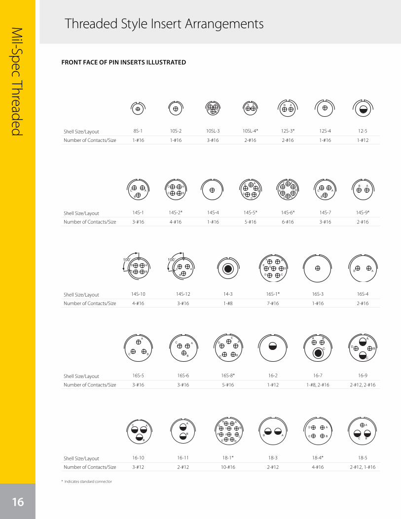
Mil-Spec Threaded
Threaded Style Insert Arrangements
16
FRONT FACE OF PIN INSERTS ILLUSTRATED
Shell Size/Layout
Number of Contacts/Size
27
front face of pin insert or rear face of socket insert illustrated
MS/Standardcontact arrangements
Insert Arrangement 16-10 16-11 16-12 16-13 18-1 18-3
Service Rating A A A A B, C, F, G = A; Bal. = Inst. D
Number of Contacts 3 2 1 2* 10 2
Contact Size 12 12 4 12 16 12
Insert Arrangement 18-4 18-5 18-6 18-7 18-8 18-9
Service Rating D D D B A Inst.
Number of Contacts 4 2 1 1 1 1 7 2 5
Contact Size 16 12 16 4 8 12 16 12 16
Insert Arrangement 18-10 18-11 18-12 18-13 18-14 18-15
Service Rating A A A A A A
Number of Contacts 4 5 6 1 3 1 1 4**
Contact Size 12 12 16 8 12 4 16 12
Insert Arrangement 18-16 18-17 18-19 18-20 18-22 18-24
Service Rating C Inst. A A D B, C, F, G = A; Bal. = Inst.
Number of Contacts 1 2 5 10 5 3 10
Contact Size 12 12 16 16 16 16 16
CONTACT LEGEND 16 12 8 4 0
* A = Iron; B = Constantan** A, C = Iron; B, D = Constantan
100° Rotationof 18-9
250° Rotationof 18-1
A
BC
A
B
C
D
B
C AA
B
AB
A
B
C
DE
F
G
H
I
J AB
A
BC
DA
B
CD
E
FG
H
A
B
C
D
E
F
G
A
BC
DA
BC
D
E
A
B
C
D
EF
A
B
A
B
C
D
A
B CD E F G
H
K
J
A B
CD
E A B
G100˚
A
B
C
D
E
F
G250˚
A
B
C
DE
F
G
H
I
J
16-10
3-#12
27
front face of pin insert or rear face of socket insert illustrated
MS/Standardcontact arrangements
Insert Arrangement 16-10 16-11 16-12 16-13 18-1 18-3
Service Rating A A A A B, C, F, G = A; Bal. = Inst. D
Number of Contacts 3 2 1 2* 10 2
Contact Size 12 12 4 12 16 12
Insert Arrangement 18-4 18-5 18-6 18-7 18-8 18-9
Service Rating D D D B A Inst.
Number of Contacts 4 2 1 1 1 1 7 2 5
Contact Size 16 12 16 4 8 12 16 12 16
Insert Arrangement 18-10 18-11 18-12 18-13 18-14 18-15
Service Rating A A A A A A
Number of Contacts 4 5 6 1 3 1 1 4**
Contact Size 12 12 16 8 12 4 16 12
Insert Arrangement 18-16 18-17 18-19 18-20 18-22 18-24
Service Rating C Inst. A A D B, C, F, G = A; Bal. = Inst.
Number of Contacts 1 2 5 10 5 3 10
Contact Size 12 12 16 16 16 16 16
CONTACT LEGEND 16 12 8 4 0
* A = Iron; B = Constantan** A, C = Iron; B, D = Constantan
100° Rotationof 18-9
250° Rotationof 18-1
A
BC
A
B
C
D
B
C AA
B
AB
A
B
C
DE
F
G
H
I
J AB
A
BC
DA
B
CD
E
FG
H
A
B
C
D
E
F
G
A
BC
DA
BC
D
E
A
B
C
D
EF
A
B
A
B
C
D
A
B CD E F G
H
K
J
A B
CD
E A B
G100˚
A
B
C
D
E
F
G250˚
A
B
C
DE
F
G
H
I
J
16-11
2-#12
27
front face of pin insert or rear face of socket insert illustrated
MS/Standardcontact arrangements
Insert Arrangement 16-10 16-11 16-12 16-13 18-1 18-3
Service Rating A A A A B, C, F, G = A; Bal. = Inst. D
Number of Contacts 3 2 1 2* 10 2
Contact Size 12 12 4 12 16 12
Insert Arrangement 18-4 18-5 18-6 18-7 18-8 18-9
Service Rating D D D B A Inst.
Number of Contacts 4 2 1 1 1 1 7 2 5
Contact Size 16 12 16 4 8 12 16 12 16
Insert Arrangement 18-10 18-11 18-12 18-13 18-14 18-15
Service Rating A A A A A A
Number of Contacts 4 5 6 1 3 1 1 4**
Contact Size 12 12 16 8 12 4 16 12
Insert Arrangement 18-16 18-17 18-19 18-20 18-22 18-24
Service Rating C Inst. A A D B, C, F, G = A; Bal. = Inst.
Number of Contacts 1 2 5 10 5 3 10
Contact Size 12 12 16 16 16 16 16
CONTACT LEGEND 16 12 8 4 0
* A = Iron; B = Constantan** A, C = Iron; B, D = Constantan
100° Rotationof 18-9
250° Rotationof 18-1
A
BC
A
B
C
D
B
C AA
B
AB
A
B
C
DE
F
G
H
I
J AB
A
BC
DA
B
CD
E
FG
H
A
B
C
D
E
F
G
A
BC
DA
BC
D
E
A
B
C
D
EF
A
B
A
B
C
D
A
B CD E F G
H
K
J
A B
CD
E A B
G100˚
A
B
C
D
E
F
G250˚
A
B
C
DE
F
G
H
I
J
18-1*
10-#16
27
front face of pin insert or rear face of socket insert illustrated
MS/Standardcontact arrangements
Insert Arrangement 16-10 16-11 16-12 16-13 18-1 18-3
Service Rating A A A A B, C, F, G = A; Bal. = Inst. D
Number of Contacts 3 2 1 2* 10 2
Contact Size 12 12 4 12 16 12
Insert Arrangement 18-4 18-5 18-6 18-7 18-8 18-9
Service Rating D D D B A Inst.
Number of Contacts 4 2 1 1 1 1 7 2 5
Contact Size 16 12 16 4 8 12 16 12 16
Insert Arrangement 18-10 18-11 18-12 18-13 18-14 18-15
Service Rating A A A A A A
Number of Contacts 4 5 6 1 3 1 1 4**
Contact Size 12 12 16 8 12 4 16 12
Insert Arrangement 18-16 18-17 18-19 18-20 18-22 18-24
Service Rating C Inst. A A D B, C, F, G = A; Bal. = Inst.
Number of Contacts 1 2 5 10 5 3 10
Contact Size 12 12 16 16 16 16 16
CONTACT LEGEND 16 12 8 4 0
* A = Iron; B = Constantan** A, C = Iron; B, D = Constantan
100° Rotationof 18-9
250° Rotationof 18-1
A
BC
A
B
C
D
B
C AA
B
AB
A
B
C
DE
F
G
H
I
J AB
A
BC
DA
B
CD
E
FG
H
A
B
C
D
E
F
G
A
BC
DA
BC
D
E
A
B
C
D
EF
A
B
A
B
C
D
A
B CD E F G
H
K
J
A B
CD
E A B
G100˚
A
B
C
D
E
F
G250˚
A
B
C
DE
F
G
H
I
J
18-3
2-#12
27
front face of pin insert or rear face of socket insert illustrated
MS/Standardcontact arrangements
Insert Arrangement 16-10 16-11 16-12 16-13 18-1 18-3
Service Rating A A A A B, C, F, G = A; Bal. = Inst. D
Number of Contacts 3 2 1 2* 10 2
Contact Size 12 12 4 12 16 12
Insert Arrangement 18-4 18-5 18-6 18-7 18-8 18-9
Service Rating D D D B A Inst.
Number of Contacts 4 2 1 1 1 1 7 2 5
Contact Size 16 12 16 4 8 12 16 12 16
Insert Arrangement 18-10 18-11 18-12 18-13 18-14 18-15
Service Rating A A A A A A
Number of Contacts 4 5 6 1 3 1 1 4**
Contact Size 12 12 16 8 12 4 16 12
Insert Arrangement 18-16 18-17 18-19 18-20 18-22 18-24
Service Rating C Inst. A A D B, C, F, G = A; Bal. = Inst.
Number of Contacts 1 2 5 10 5 3 10
Contact Size 12 12 16 16 16 16 16
CONTACT LEGEND 16 12 8 4 0
* A = Iron; B = Constantan** A, C = Iron; B, D = Constantan
100° Rotationof 18-9
250° Rotationof 18-1
A
BC
A
B
C
D
B
C AA
B
AB
A
B
C
DE
F
G
H
I
J AB
A
BC
DA
B
CD
E
FG
H
A
B
C
D
E
F
G
A
BC
DA
BC
D
E
A
B
C
D
EF
A
B
A
B
C
D
A
B CD E F G
H
K
J
A B
CD
E A B
G100˚
A
B
C
D
E
F
G250˚
A
B
C
DE
F
G
H
I
J
18-4*
4-#16
27
front face of pin insert or rear face of socket insert illustrated
MS/Standardcontact arrangements
Insert Arrangement 16-10 16-11 16-12 16-13 18-1 18-3
Service Rating A A A A B, C, F, G = A; Bal. = Inst. D
Number of Contacts 3 2 1 2* 10 2
Contact Size 12 12 4 12 16 12
Insert Arrangement 18-4 18-5 18-6 18-7 18-8 18-9
Service Rating D D D B A Inst.
Number of Contacts 4 2 1 1 1 1 7 2 5
Contact Size 16 12 16 4 8 12 16 12 16
Insert Arrangement 18-10 18-11 18-12 18-13 18-14 18-15
Service Rating A A A A A A
Number of Contacts 4 5 6 1 3 1 1 4**
Contact Size 12 12 16 8 12 4 16 12
Insert Arrangement 18-16 18-17 18-19 18-20 18-22 18-24
Service Rating C Inst. A A D B, C, F, G = A; Bal. = Inst.
Number of Contacts 1 2 5 10 5 3 10
Contact Size 12 12 16 16 16 16 16
CONTACT LEGEND 16 12 8 4 0
* A = Iron; B = Constantan** A, C = Iron; B, D = Constantan
100° Rotationof 18-9
250° Rotationof 18-1
A
BC
A
B
C
D
B
C AA
B
AB
A
B
C
DE
F
G
H
I
J AB
A
BC
DA
B
CD
E
FG
H
A
B
C
D
E
F
G
A
BC
DA
BC
D
E
A
B
C
D
EF
A
B
A
B
C
D
A
B CD E F G
H
K
J
A B
CD
E A B
G100˚
A
B
C
D
E
F
G250˚
A
B
C
DE
F
G
H
I
J
18-5
2-#12, 1-#16
* Indicates standard connector
Shell Size/Layout
Number of Contacts/Size
Shell Size/Layout
Number of Contacts/Size
Shell Size/Layout
Number of Contacts/Size
Shell Size/Layout
Number of Contacts/Size
Shell Size/Layout
Number of Contacts/Size
27
front face of pin insert or rear face of socket insert illustrated
MS/Standardcontact arrangements
Insert Arrangement 16-10 16-11 16-12 16-13 18-1 18-3
Service Rating A A A A B, C, F, G = A; Bal. = Inst. D
Number of Contacts 3 2 1 2* 10 2
Contact Size 12 12 4 12 16 12
Insert Arrangement 18-4 18-5 18-6 18-7 18-8 18-9
Service Rating D D D B A Inst.
Number of Contacts 4 2 1 1 1 1 7 2 5
Contact Size 16 12 16 4 8 12 16 12 16
Insert Arrangement 18-10 18-11 18-12 18-13 18-14 18-15
Service Rating A A A A A A
Number of Contacts 4 5 6 1 3 1 1 4**
Contact Size 12 12 16 8 12 4 16 12
Insert Arrangement 18-16 18-17 18-19 18-20 18-22 18-24
Service Rating C Inst. A A D B, C, F, G = A; Bal. = Inst.
Number of Contacts 1 2 5 10 5 3 10
Contact Size 12 12 16 16 16 16 16
CONTACT LEGEND 16 12 8 4 0
* A = Iron; B = Constantan** A, C = Iron; B, D = Constantan
100° Rotationof 18-9
250° Rotationof 18-1
A
BC
A
B
C
D
B
C AA
B
AB
A
B
C
DE
F
G
H
I
J AB
A
BC
DA
B
CD
E
FG
H
A
B
C
D
E
F
G
A
BC
DA
BC
D
E
A
B
C
D
EF
A
B
A
B
C
D
A
B CD E F G
H
K
J
A B
CD
E A B
G100˚
A
B
C
D
E
F
G250˚
A
B
C
DE
F
G
H
I
J
18-7
1-#8
27
front face of pin insert or rear face of socket insert illustrated
MS/Standardcontact arrangements
Insert Arrangement 16-10 16-11 16-12 16-13 18-1 18-3
Service Rating A A A A B, C, F, G = A; Bal. = Inst. D
Number of Contacts 3 2 1 2* 10 2
Contact Size 12 12 4 12 16 12
Insert Arrangement 18-4 18-5 18-6 18-7 18-8 18-9
Service Rating D D D B A Inst.
Number of Contacts 4 2 1 1 1 1 7 2 5
Contact Size 16 12 16 4 8 12 16 12 16
Insert Arrangement 18-10 18-11 18-12 18-13 18-14 18-15
Service Rating A A A A A A
Number of Contacts 4 5 6 1 3 1 1 4**
Contact Size 12 12 16 8 12 4 16 12
Insert Arrangement 18-16 18-17 18-19 18-20 18-22 18-24
Service Rating C Inst. A A D B, C, F, G = A; Bal. = Inst.
Number of Contacts 1 2 5 10 5 3 10
Contact Size 12 12 16 16 16 16 16
CONTACT LEGEND 16 12 8 4 0
* A = Iron; B = Constantan** A, C = Iron; B, D = Constantan
100° Rotationof 18-9
250° Rotationof 18-1
A
BC
A
B
C
D
B
C AA
B
AB
A
B
C
DE
F
G
H
I
J AB
A
BC
DA
B
CD
E
FG
H
A
B
C
D
E
F
G
A
BC
DA
BC
D
E
A
B
C
D
EF
A
B
A
B
C
D
A
B CD E F G
H
K
J
A B
CD
E A B
G100˚
A
B
C
D
E
F
G250˚
A
B
C
DE
F
G
H
I
J
18-13
1-#8, 3-#12
27
front face of pin insert or rear face of socket insert illustrated
MS/Standardcontact arrangements
Insert Arrangement 16-10 16-11 16-12 16-13 18-1 18-3
Service Rating A A A A B, C, F, G = A; Bal. = Inst. D
Number of Contacts 3 2 1 2* 10 2
Contact Size 12 12 4 12 16 12
Insert Arrangement 18-4 18-5 18-6 18-7 18-8 18-9
Service Rating D D D B A Inst.
Number of Contacts 4 2 1 1 1 1 7 2 5
Contact Size 16 12 16 4 8 12 16 12 16
Insert Arrangement 18-10 18-11 18-12 18-13 18-14 18-15
Service Rating A A A A A A
Number of Contacts 4 5 6 1 3 1 1 4**
Contact Size 12 12 16 8 12 4 16 12
Insert Arrangement 18-16 18-17 18-19 18-20 18-22 18-24
Service Rating C Inst. A A D B, C, F, G = A; Bal. = Inst.
Number of Contacts 1 2 5 10 5 3 10
Contact Size 12 12 16 16 16 16 16
CONTACT LEGEND 16 12 8 4 0
* A = Iron; B = Constantan** A, C = Iron; B, D = Constantan
100° Rotationof 18-9
250° Rotationof 18-1
A
BC
A
B
C
D
B
C AA
B
AB
A
B
C
DE
F
G
H
I
J AB
A
BC
DA
B
CD
E
FG
H
A
B
C
D
E
F
G
A
BC
DA
BC
D
E
A
B
C
D
EF
A
B
A
B
C
D
A
B CD E F G
H
K
J
A B
CD
E A B
G100˚
A
B
C
D
E
F
G250˚
A
B
C
DE
F
G
H
I
J
18-24
10-#16
28
front face of pin insert or rear face of socket insert illustrated
MS/Standardcontact arrangements
Insert Arrangement 18-29 18-30 18-31 20-2 20-3 20-4
Service Rating A A A D D D
Number of Contacts 5 5 5 1 3 4
Contact Size 16 16 16 0 12 12
Insert Arrangement 20-6 20-7 20-8 20-9 20-11 20-12
Service Rating D A, B, H, G = D; C, D, E, F = A Inst. H = D; Bal. = A Inst. A
Number of Contacts 3 8 2 4 1 7 13 1 1
Contact Size 16 16 8 16 12 16 16 4 16
Insert Arrangement 20-14 20-15 20-16 20-17 20-18 20-19
Service Rating A A A A A A
Number of Contacts 2 3 7 2 7 5 1 3 6 3
Contact Size 8 12 12 12 16 12 16 12 16 8
CONTACT LEGEND 16 12 8 4 0
110° Rotationof 18-20
260° Rotationof 18-20
A
BC
D
E A
BC
A
B
D
C
A
BC
A
B
C
DE
F
GH
A
B
C
D
E F
A
B
C
DE
F
G H
A
B C
D
E
F
G H
J
K
L
M
N
A
B
A
B
C
D
E A
B
CD
E G
F
AB
C
D
EF
G
HI
A
BC
D
E
F
A
B
C
D
E
F
GH
I
A
BC
110˚A B
CD
E
260˚
A B
CD
E
20-6
3-#16
28
front face of pin insert or rear face of socket insert illustrated
MS/Standardcontact arrangements
Insert Arrangement 18-29 18-30 18-31 20-2 20-3 20-4
Service Rating A A A D D D
Number of Contacts 5 5 5 1 3 4
Contact Size 16 16 16 0 12 12
Insert Arrangement 20-6 20-7 20-8 20-9 20-11 20-12
Service Rating D A, B, H, G = D; C, D, E, F = A Inst. H = D; Bal. = A Inst. A
Number of Contacts 3 8 2 4 1 7 13 1 1
Contact Size 16 16 8 16 12 16 16 4 16
Insert Arrangement 20-14 20-15 20-16 20-17 20-18 20-19
Service Rating A A A A A A
Number of Contacts 2 3 7 2 7 5 1 3 6 3
Contact Size 8 12 12 12 16 12 16 12 16 8
CONTACT LEGEND 16 12 8 4 0
110° Rotationof 18-20
260° Rotationof 18-20
A
BC
D
E A
BC
A
B
D
C
A
BC
A
B
C
DE
F
GH
A
B
C
D
E F
A
B
C
DE
F
G H
A
B C
D
E
F
G H
J
K
L
M
N
A
B
A
B
C
D
E A
B
CD
E G
F
AB
C
D
EF
G
HI
A
BC
D
E
F
A
B
C
D
E
F
GH
I
A
BC
110˚A B
CD
E
260˚
A B
CD
E
20-15*
7-#12
27
front face of pin insert or rear face of socket insert illustrated
MS/Standardcontact arrangements
Insert Arrangement 16-10 16-11 16-12 16-13 18-1 18-3
Service Rating A A A A B, C, F, G = A; Bal. = Inst. D
Number of Contacts 3 2 1 2* 10 2
Contact Size 12 12 4 12 16 12
Insert Arrangement 18-4 18-5 18-6 18-7 18-8 18-9
Service Rating D D D B A Inst.
Number of Contacts 4 2 1 1 1 1 7 2 5
Contact Size 16 12 16 4 8 12 16 12 16
Insert Arrangement 18-10 18-11 18-12 18-13 18-14 18-15
Service Rating A A A A A A
Number of Contacts 4 5 6 1 3 1 1 4**
Contact Size 12 12 16 8 12 4 16 12
Insert Arrangement 18-16 18-17 18-19 18-20 18-22 18-24
Service Rating C Inst. A A D B, C, F, G = A; Bal. = Inst.
Number of Contacts 1 2 5 10 5 3 10
Contact Size 12 12 16 16 16 16 16
CONTACT LEGEND 16 12 8 4 0
* A = Iron; B = Constantan** A, C = Iron; B, D = Constantan
100° Rotationof 18-9
250° Rotationof 18-1
A
BC
A
B
C
D
B
C AA
B
AB
A
B
C
DE
F
G
H
I
J AB
A
BC
DA
B
CD
E
FG
H
A
B
C
D
E
F
G
A
BC
DA
BC
D
E
A
B
C
D
EF
A
B
A
B
C
D
A
B CD E F G
H
K
J
A B
CD
E A B
G100˚
A
B
C
D
E
F
G250˚
A
B
C
DE
F
G
H
I
J
18-8*
1-#12, 7-#16
27
front face of pin insert or rear face of socket insert illustrated
MS/Standardcontact arrangements
Insert Arrangement 16-10 16-11 16-12 16-13 18-1 18-3
Service Rating A A A A B, C, F, G = A; Bal. = Inst. D
Number of Contacts 3 2 1 2* 10 2
Contact Size 12 12 4 12 16 12
Insert Arrangement 18-4 18-5 18-6 18-7 18-8 18-9
Service Rating D D D B A Inst.
Number of Contacts 4 2 1 1 1 1 7 2 5
Contact Size 16 12 16 4 8 12 16 12 16
Insert Arrangement 18-10 18-11 18-12 18-13 18-14 18-15
Service Rating A A A A A A
Number of Contacts 4 5 6 1 3 1 1 4**
Contact Size 12 12 16 8 12 4 16 12
Insert Arrangement 18-16 18-17 18-19 18-20 18-22 18-24
Service Rating C Inst. A A D B, C, F, G = A; Bal. = Inst.
Number of Contacts 1 2 5 10 5 3 10
Contact Size 12 12 16 16 16 16 16
CONTACT LEGEND 16 12 8 4 0
* A = Iron; B = Constantan** A, C = Iron; B, D = Constantan
100° Rotationof 18-9
250° Rotationof 18-1
A
BC
A
B
C
D
B
C AA
B
AB
A
B
C
DE
F
G
H
I
J AB
A
BC
DA
B
CD
E
FG
H
A
B
C
D
E
F
G
A
BC
DA
BC
D
E
A
B
C
D
EF
A
B
A
B
C
D
A
B CD E F G
H
K
J
A B
CD
E A B
G100˚
A
B
C
D
E
F
G250˚
A
B
C
DE
F
G
H
I
J
18-16
1-#12
28
front face of pin insert or rear face of socket insert illustrated
MS/Standardcontact arrangements
Insert Arrangement 18-29 18-30 18-31 20-2 20-3 20-4
Service Rating A A A D D D
Number of Contacts 5 5 5 1 3 4
Contact Size 16 16 16 0 12 12
Insert Arrangement 20-6 20-7 20-8 20-9 20-11 20-12
Service Rating D A, B, H, G = D; C, D, E, F = A Inst. H = D; Bal. = A Inst. A
Number of Contacts 3 8 2 4 1 7 13 1 1
Contact Size 16 16 8 16 12 16 16 4 16
Insert Arrangement 20-14 20-15 20-16 20-17 20-18 20-19
Service Rating A A A A A A
Number of Contacts 2 3 7 2 7 5 1 3 6 3
Contact Size 8 12 12 12 16 12 16 12 16 8
CONTACT LEGEND 16 12 8 4 0
110° Rotationof 18-20
260° Rotationof 18-20
A
BC
D
E A
BC
A
B
D
C
A
BC
A
B
C
DE
F
GH
A
B
C
D
E F
A
B
C
DE
F
G H
A
B C
D
E
F
G H
J
K
L
M
N
A
B
A
B
C
D
E A
B
CD
E G
F
AB
C
D
EF
G
HI
A
BC
D
E
F
A
B
C
D
E
F
GH
I
A
BC
110˚A B
CD
E
260˚
A B
CD
E
18-29
5-#16
28
front face of pin insert or rear face of socket insert illustrated
MS/Standardcontact arrangements
Insert Arrangement 18-29 18-30 18-31 20-2 20-3 20-4
Service Rating A A A D D D
Number of Contacts 5 5 5 1 3 4
Contact Size 16 16 16 0 12 12
Insert Arrangement 20-6 20-7 20-8 20-9 20-11 20-12
Service Rating D A, B, H, G = D; C, D, E, F = A Inst. H = D; Bal. = A Inst. A
Number of Contacts 3 8 2 4 1 7 13 1 1
Contact Size 16 16 8 16 12 16 16 4 16
Insert Arrangement 20-14 20-15 20-16 20-17 20-18 20-19
Service Rating A A A A A A
Number of Contacts 2 3 7 2 7 5 1 3 6 3
Contact Size 8 12 12 12 16 12 16 12 16 8
CONTACT LEGEND 16 12 8 4 0
110° Rotationof 18-20
260° Rotationof 18-20
A
BC
D
E A
BC
A
B
D
C
A
BC
A
B
C
DE
F
GH
A
B
C
D
E F
A
B
C
DE
F
G H
A
B C
D
E
F
G H
J
K
L
M
N
A
B
A
B
C
D
E A
B
CD
E G
F
AB
C
D
EF
G
HI
A
BC
D
E
F
A
B
C
D
E
F
GH
I
A
BC
110˚A B
CD
E
260˚
A B
CD
E
20-7*
8-#16
28
front face of pin insert or rear face of socket insert illustrated
MS/Standardcontact arrangements
Insert Arrangement 18-29 18-30 18-31 20-2 20-3 20-4
Service Rating A A A D D D
Number of Contacts 5 5 5 1 3 4
Contact Size 16 16 16 0 12 12
Insert Arrangement 20-6 20-7 20-8 20-9 20-11 20-12
Service Rating D A, B, H, G = D; C, D, E, F = A Inst. H = D; Bal. = A Inst. A
Number of Contacts 3 8 2 4 1 7 13 1 1
Contact Size 16 16 8 16 12 16 16 4 16
Insert Arrangement 20-14 20-15 20-16 20-17 20-18 20-19
Service Rating A A A A A A
Number of Contacts 2 3 7 2 7 5 1 3 6 3
Contact Size 8 12 12 12 16 12 16 12 16 8
CONTACT LEGEND 16 12 8 4 0
110° Rotationof 18-20
260° Rotationof 18-20
A
BC
D
E A
BC
A
B
D
C
A
BC
A
B
C
DE
F
GH
A
B
C
D
E F
A
B
C
DE
F
G H
A
B C
D
E
F
G H
J
K
L
M
N
A
B
A
B
C
D
E A
B
CD
E G
F
AB
C
D
EF
G
HI
A
BC
D
E
F
A
B
C
D
E
F
GH
I
A
BC
110˚A B
CD
E
260˚
A B
CD
E
20-16
2-#12, 7-#16
27
front face of pin insert or rear face of socket insert illustrated
MS/Standardcontact arrangements
Insert Arrangement 16-10 16-11 16-12 16-13 18-1 18-3
Service Rating A A A A B, C, F, G = A; Bal. = Inst. D
Number of Contacts 3 2 1 2* 10 2
Contact Size 12 12 4 12 16 12
Insert Arrangement 18-4 18-5 18-6 18-7 18-8 18-9
Service Rating D D D B A Inst.
Number of Contacts 4 2 1 1 1 1 7 2 5
Contact Size 16 12 16 4 8 12 16 12 16
Insert Arrangement 18-10 18-11 18-12 18-13 18-14 18-15
Service Rating A A A A A A
Number of Contacts 4 5 6 1 3 1 1 4**
Contact Size 12 12 16 8 12 4 16 12
Insert Arrangement 18-16 18-17 18-19 18-20 18-22 18-24
Service Rating C Inst. A A D B, C, F, G = A; Bal. = Inst.
Number of Contacts 1 2 5 10 5 3 10
Contact Size 12 12 16 16 16 16 16
CONTACT LEGEND 16 12 8 4 0
* A = Iron; B = Constantan** A, C = Iron; B, D = Constantan
100° Rotationof 18-9
250° Rotationof 18-1
A
BC
A
B
C
D
B
C AA
B
AB
A
B
C
DE
F
G
H
I
J AB
A
BC
DA
B
CD
E
FG
H
A
B
C
D
E
F
G
A
BC
DA
BC
D
E
A
B
C
D
EF
A
B
A
B
C
D
A
B CD E F G
H
K
J
A B
CD
E A B
G100˚
A
B
C
D
E
F
G250˚
A
B
C
DE
F
G
H
I
J
18-9
2-#12, 5-#16
27
front face of pin insert or rear face of socket insert illustrated
MS/Standardcontact arrangements
Insert Arrangement 16-10 16-11 16-12 16-13 18-1 18-3
Service Rating A A A A B, C, F, G = A; Bal. = Inst. D
Number of Contacts 3 2 1 2* 10 2
Contact Size 12 12 4 12 16 12
Insert Arrangement 18-4 18-5 18-6 18-7 18-8 18-9
Service Rating D D D B A Inst.
Number of Contacts 4 2 1 1 1 1 7 2 5
Contact Size 16 12 16 4 8 12 16 12 16
Insert Arrangement 18-10 18-11 18-12 18-13 18-14 18-15
Service Rating A A A A A A
Number of Contacts 4 5 6 1 3 1 1 4**
Contact Size 12 12 16 8 12 4 16 12
Insert Arrangement 18-16 18-17 18-19 18-20 18-22 18-24
Service Rating C Inst. A A D B, C, F, G = A; Bal. = Inst.
Number of Contacts 1 2 5 10 5 3 10
Contact Size 12 12 16 16 16 16 16
CONTACT LEGEND 16 12 8 4 0
* A = Iron; B = Constantan** A, C = Iron; B, D = Constantan
100° Rotationof 18-9
250° Rotationof 18-1
A
BC
A
B
C
D
B
C AA
B
AB
A
B
C
DE
F
G
H
I
J AB
A
BC
DA
B
CD
E
FG
H
A
B
C
D
E
F
G
A
BC
DA
BC
D
E
A
B
C
D
EF
A
B
A
B
C
D
A
B CD E F G
H
K
J
A B
CD
E A B
G100˚
A
B
C
D
E
F
G250˚
A
B
C
DE
F
G
H
I
J
18-17
2-#12, 5-#16
28
front face of pin insert or rear face of socket insert illustrated
MS/Standardcontact arrangements
Insert Arrangement 18-29 18-30 18-31 20-2 20-3 20-4
Service Rating A A A D D D
Number of Contacts 5 5 5 1 3 4
Contact Size 16 16 16 0 12 12
Insert Arrangement 20-6 20-7 20-8 20-9 20-11 20-12
Service Rating D A, B, H, G = D; C, D, E, F = A Inst. H = D; Bal. = A Inst. A
Number of Contacts 3 8 2 4 1 7 13 1 1
Contact Size 16 16 8 16 12 16 16 4 16
Insert Arrangement 20-14 20-15 20-16 20-17 20-18 20-19
Service Rating A A A A A A
Number of Contacts 2 3 7 2 7 5 1 3 6 3
Contact Size 8 12 12 12 16 12 16 12 16 8
CONTACT LEGEND 16 12 8 4 0
110° Rotationof 18-20
260° Rotationof 18-20
A
BC
D
E A
BC
A
B
D
C
A
BC
A
B
C
DE
F
GH
A
B
C
D
E F
A
B
C
DE
F
G H
A
B C
D
E
F
G H
J
K
L
M
N
A
B
A
B
C
D
E A
B
CD
E G
F
AB
C
D
EF
G
HI
A
BC
D
E
F
A
B
C
D
E
F
GH
I
A
BC
110˚A B
CD
E
260˚
A B
CD
E
18-30
5-#16
28
front face of pin insert or rear face of socket insert illustrated
MS/Standardcontact arrangements
Insert Arrangement 18-29 18-30 18-31 20-2 20-3 20-4
Service Rating A A A D D D
Number of Contacts 5 5 5 1 3 4
Contact Size 16 16 16 0 12 12
Insert Arrangement 20-6 20-7 20-8 20-9 20-11 20-12
Service Rating D A, B, H, G = D; C, D, E, F = A Inst. H = D; Bal. = A Inst. A
Number of Contacts 3 8 2 4 1 7 13 1 1
Contact Size 16 16 8 16 12 16 16 4 16
Insert Arrangement 20-14 20-15 20-16 20-17 20-18 20-19
Service Rating A A A A A A
Number of Contacts 2 3 7 2 7 5 1 3 6 3
Contact Size 8 12 12 12 16 12 16 12 16 8
CONTACT LEGEND 16 12 8 4 0
110° Rotationof 18-20
260° Rotationof 18-20
A
BC
D
E A
BC
A
B
D
C
A
BC
A
B
C
DE
F
GH
A
B
C
D
E F
A
B
C
DE
F
G H
A
B C
D
E
F
G H
J
K
L
M
N
A
B
A
B
C
D
E A
B
CD
E G
F
AB
C
D
EF
G
HI
A
BC
D
E
F
A
B
C
D
E
F
GH
I
A
BC
110˚A B
CD
E
260˚
A B
CD
E
20-8
2-#8, 4-#16
28
front face of pin insert or rear face of socket insert illustrated
MS/Standardcontact arrangements
Insert Arrangement 18-29 18-30 18-31 20-2 20-3 20-4
Service Rating A A A D D D
Number of Contacts 5 5 5 1 3 4
Contact Size 16 16 16 0 12 12
Insert Arrangement 20-6 20-7 20-8 20-9 20-11 20-12
Service Rating D A, B, H, G = D; C, D, E, F = A Inst. H = D; Bal. = A Inst. A
Number of Contacts 3 8 2 4 1 7 13 1 1
Contact Size 16 16 8 16 12 16 16 4 16
Insert Arrangement 20-14 20-15 20-16 20-17 20-18 20-19
Service Rating A A A A A A
Number of Contacts 2 3 7 2 7 5 1 3 6 3
Contact Size 8 12 12 12 16 12 16 12 16 8
CONTACT LEGEND 16 12 8 4 0
110° Rotationof 18-20
260° Rotationof 18-20
A
BC
D
E A
BC
A
B
D
C
A
BC
A
B
C
DE
F
GH
A
B
C
D
E F
A
B
C
DE
F
G H
A
B C
D
E
F
G H
J
K
L
M
N
A
B
A
B
C
D
E A
B
CD
E G
F
AB
C
D
EF
G
HI
A
BC
D
E
F
A
B
C
D
E
F
GH
I
A
BC
110˚A B
CD
E
260˚
A B
CD
E
20-17
5-#12, 1-#16
27
front face of pin insert or rear face of socket insert illustrated
MS/Standardcontact arrangements
Insert Arrangement 16-10 16-11 16-12 16-13 18-1 18-3
Service Rating A A A A B, C, F, G = A; Bal. = Inst. D
Number of Contacts 3 2 1 2* 10 2
Contact Size 12 12 4 12 16 12
Insert Arrangement 18-4 18-5 18-6 18-7 18-8 18-9
Service Rating D D D B A Inst.
Number of Contacts 4 2 1 1 1 1 7 2 5
Contact Size 16 12 16 4 8 12 16 12 16
Insert Arrangement 18-10 18-11 18-12 18-13 18-14 18-15
Service Rating A A A A A A
Number of Contacts 4 5 6 1 3 1 1 4**
Contact Size 12 12 16 8 12 4 16 12
Insert Arrangement 18-16 18-17 18-19 18-20 18-22 18-24
Service Rating C Inst. A A D B, C, F, G = A; Bal. = Inst.
Number of Contacts 1 2 5 10 5 3 10
Contact Size 12 12 16 16 16 16 16
CONTACT LEGEND 16 12 8 4 0
* A = Iron; B = Constantan** A, C = Iron; B, D = Constantan
100° Rotationof 18-9
250° Rotationof 18-1
A
BC
A
B
C
D
B
C AA
B
AB
A
B
C
DE
F
G
H
I
J AB
A
BC
DA
B
CD
E
FG
H
A
B
C
D
E
F
G
A
BC
DA
BC
D
E
A
B
C
D
EF
A
B
A
B
C
D
A
B CD E F G
H
K
J
A B
CD
E A B
G100˚
A
B
C
D
E
F
G250˚
A
B
C
DE
F
G
H
I
J
18-10*
4-#12
27
front face of pin insert or rear face of socket insert illustrated
MS/Standardcontact arrangements
Insert Arrangement 16-10 16-11 16-12 16-13 18-1 18-3
Service Rating A A A A B, C, F, G = A; Bal. = Inst. D
Number of Contacts 3 2 1 2* 10 2
Contact Size 12 12 4 12 16 12
Insert Arrangement 18-4 18-5 18-6 18-7 18-8 18-9
Service Rating D D D B A Inst.
Number of Contacts 4 2 1 1 1 1 7 2 5
Contact Size 16 12 16 4 8 12 16 12 16
Insert Arrangement 18-10 18-11 18-12 18-13 18-14 18-15
Service Rating A A A A A A
Number of Contacts 4 5 6 1 3 1 1 4**
Contact Size 12 12 16 8 12 4 16 12
Insert Arrangement 18-16 18-17 18-19 18-20 18-22 18-24
Service Rating C Inst. A A D B, C, F, G = A; Bal. = Inst.
Number of Contacts 1 2 5 10 5 3 10
Contact Size 12 12 16 16 16 16 16
CONTACT LEGEND 16 12 8 4 0
* A = Iron; B = Constantan** A, C = Iron; B, D = Constantan
100° Rotationof 18-9
250° Rotationof 18-1
A
BC
A
B
C
D
B
C AA
B
AB
A
B
C
DE
F
G
H
I
J AB
A
BC
DA
B
CD
E
FG
H
A
B
C
D
E
F
G
A
BC
DA
BC
D
E
A
B
C
D
EF
A
B
A
B
C
D
A
B CD E F G
H
K
J
A B
CD
E A B
G100˚
A
B
C
D
E
F
G250˚
A
B
C
DE
F
G
H
I
J
18-19
10-#16
28
front face of pin insert or rear face of socket insert illustrated
MS/Standardcontact arrangements
Insert Arrangement 18-29 18-30 18-31 20-2 20-3 20-4
Service Rating A A A D D D
Number of Contacts 5 5 5 1 3 4
Contact Size 16 16 16 0 12 12
Insert Arrangement 20-6 20-7 20-8 20-9 20-11 20-12
Service Rating D A, B, H, G = D; C, D, E, F = A Inst. H = D; Bal. = A Inst. A
Number of Contacts 3 8 2 4 1 7 13 1 1
Contact Size 16 16 8 16 12 16 16 4 16
Insert Arrangement 20-14 20-15 20-16 20-17 20-18 20-19
Service Rating A A A A A A
Number of Contacts 2 3 7 2 7 5 1 3 6 3
Contact Size 8 12 12 12 16 12 16 12 16 8
CONTACT LEGEND 16 12 8 4 0
110° Rotationof 18-20
260° Rotationof 18-20
A
BC
D
E A
BC
A
B
D
C
A
BC
A
B
C
DE
F
GH
A
B
C
D
E F
A
B
C
DE
F
G H
A
B C
D
E
F
G H
J
K
L
M
N
A
B
A
B
C
D
E A
B
CD
E G
F
AB
C
D
EF
G
HI
A
BC
D
E
F
A
B
C
D
E
F
GH
I
A
BC
110˚A B
CD
E
260˚
A B
CD
E
18-31
5-#16
28
front face of pin insert or rear face of socket insert illustrated
MS/Standardcontact arrangements
Insert Arrangement 18-29 18-30 18-31 20-2 20-3 20-4
Service Rating A A A D D D
Number of Contacts 5 5 5 1 3 4
Contact Size 16 16 16 0 12 12
Insert Arrangement 20-6 20-7 20-8 20-9 20-11 20-12
Service Rating D A, B, H, G = D; C, D, E, F = A Inst. H = D; Bal. = A Inst. A
Number of Contacts 3 8 2 4 1 7 13 1 1
Contact Size 16 16 8 16 12 16 16 4 16
Insert Arrangement 20-14 20-15 20-16 20-17 20-18 20-19
Service Rating A A A A A A
Number of Contacts 2 3 7 2 7 5 1 3 6 3
Contact Size 8 12 12 12 16 12 16 12 16 8
CONTACT LEGEND 16 12 8 4 0
110° Rotationof 18-20
260° Rotationof 18-20
A
BC
D
E A
BC
A
B
D
C
A
BC
A
B
C
DE
F
GH
A
B
C
D
E F
A
B
C
DE
F
G H
A
B C
D
E
F
G H
J
K
L
M
N
A
B
A
B
C
D
E A
B
CD
E G
F
AB
C
D
EF
G
HI
A
BC
D
E
F
A
B
C
D
E
F
GH
I
A
BC
110˚A B
CD
E
260˚
A B
CD
E
20-9
1-#12, 7-#16
28
front face of pin insert or rear face of socket insert illustrated
MS/Standardcontact arrangements
Insert Arrangement 18-29 18-30 18-31 20-2 20-3 20-4
Service Rating A A A D D D
Number of Contacts 5 5 5 1 3 4
Contact Size 16 16 16 0 12 12
Insert Arrangement 20-6 20-7 20-8 20-9 20-11 20-12
Service Rating D A, B, H, G = D; C, D, E, F = A Inst. H = D; Bal. = A Inst. A
Number of Contacts 3 8 2 4 1 7 13 1 1
Contact Size 16 16 8 16 12 16 16 4 16
Insert Arrangement 20-14 20-15 20-16 20-17 20-18 20-19
Service Rating A A A A A A
Number of Contacts 2 3 7 2 7 5 1 3 6 3
Contact Size 8 12 12 12 16 12 16 12 16 8
CONTACT LEGEND 16 12 8 4 0
110° Rotationof 18-20
260° Rotationof 18-20
A
BC
D
E A
BC
A
B
D
C
A
BC
A
B
C
DE
F
GH
A
B
C
D
E F
A
B
C
DE
F
G H
A
B C
D
E
F
G H
J
K
L
M
N
A
B
A
B
C
D
E A
B
CD
E G
F
AB
C
D
EF
G
HI
A
BC
D
E
F
A
B
C
D
E
F
GH
I
A
BC
110˚A B
CD
E
260˚
A B
CD
E
20-18*
3-#12, 6-#16
27
front face of pin insert or rear face of socket insert illustrated
MS/Standardcontact arrangements
Insert Arrangement 16-10 16-11 16-12 16-13 18-1 18-3
Service Rating A A A A B, C, F, G = A; Bal. = Inst. D
Number of Contacts 3 2 1 2* 10 2
Contact Size 12 12 4 12 16 12
Insert Arrangement 18-4 18-5 18-6 18-7 18-8 18-9
Service Rating D D D B A Inst.
Number of Contacts 4 2 1 1 1 1 7 2 5
Contact Size 16 12 16 4 8 12 16 12 16
Insert Arrangement 18-10 18-11 18-12 18-13 18-14 18-15
Service Rating A A A A A A
Number of Contacts 4 5 6 1 3 1 1 4**
Contact Size 12 12 16 8 12 4 16 12
Insert Arrangement 18-16 18-17 18-19 18-20 18-22 18-24
Service Rating C Inst. A A D B, C, F, G = A; Bal. = Inst.
Number of Contacts 1 2 5 10 5 3 10
Contact Size 12 12 16 16 16 16 16
CONTACT LEGEND 16 12 8 4 0
* A = Iron; B = Constantan** A, C = Iron; B, D = Constantan
100° Rotationof 18-9
250° Rotationof 18-1
A
BC
A
B
C
D
B
C AA
B
AB
A
B
C
DE
F
G
H
I
J AB
A
BC
DA
B
CD
E
FG
H
A
B
C
D
E
F
G
A
BC
DA
BC
D
E
A
B
C
D
EF
A
B
A
B
C
D
A
B CD E F G
H
K
J
A B
CD
E A B
G100˚
A
B
C
D
E
F
G250˚
A
B
C
DE
F
G
H
I
J
18-11*
5-#12
27
front face of pin insert or rear face of socket insert illustrated
MS/Standardcontact arrangements
Insert Arrangement 16-10 16-11 16-12 16-13 18-1 18-3
Service Rating A A A A B, C, F, G = A; Bal. = Inst. D
Number of Contacts 3 2 1 2* 10 2
Contact Size 12 12 4 12 16 12
Insert Arrangement 18-4 18-5 18-6 18-7 18-8 18-9
Service Rating D D D B A Inst.
Number of Contacts 4 2 1 1 1 1 7 2 5
Contact Size 16 12 16 4 8 12 16 12 16
Insert Arrangement 18-10 18-11 18-12 18-13 18-14 18-15
Service Rating A A A A A A
Number of Contacts 4 5 6 1 3 1 1 4**
Contact Size 12 12 16 8 12 4 16 12
Insert Arrangement 18-16 18-17 18-19 18-20 18-22 18-24
Service Rating C Inst. A A D B, C, F, G = A; Bal. = Inst.
Number of Contacts 1 2 5 10 5 3 10
Contact Size 12 12 16 16 16 16 16
CONTACT LEGEND 16 12 8 4 0
* A = Iron; B = Constantan** A, C = Iron; B, D = Constantan
100° Rotationof 18-9
250° Rotationof 18-1
A
BC
A
B
C
D
B
C AA
B
AB
A
B
C
DE
F
G
H
I
J AB
A
BC
DA
B
CD
E
FG
H
A
B
C
D
E
F
G
A
BC
DA
BC
D
E
A
B
C
D
EF
A
B
A
B
C
D
A
B CD E F G
H
K
J
A B
CD
E A B
G100˚
A
B
C
D
E
F
G250˚
A
B
C
DE
F
G
H
I
J
18-20
5-#16
28
front face of pin insert or rear face of socket insert illustrated
MS/Standardcontact arrangements
Insert Arrangement 18-29 18-30 18-31 20-2 20-3 20-4
Service Rating A A A D D D
Number of Contacts 5 5 5 1 3 4
Contact Size 16 16 16 0 12 12
Insert Arrangement 20-6 20-7 20-8 20-9 20-11 20-12
Service Rating D A, B, H, G = D; C, D, E, F = A Inst. H = D; Bal. = A Inst. A
Number of Contacts 3 8 2 4 1 7 13 1 1
Contact Size 16 16 8 16 12 16 16 4 16
Insert Arrangement 20-14 20-15 20-16 20-17 20-18 20-19
Service Rating A A A A A A
Number of Contacts 2 3 7 2 7 5 1 3 6 3
Contact Size 8 12 12 12 16 12 16 12 16 8
CONTACT LEGEND 16 12 8 4 0
110° Rotationof 18-20
260° Rotationof 18-20
A
BC
D
E A
BC
A
B
D
C
A
BC
A
B
C
DE
F
GH
A
B
C
D
E F
A
B
C
DE
F
G H
A
B C
D
E
F
G H
J
K
L
M
N
A
B
A
B
C
D
E A
B
CD
E G
F
AB
C
D
EF
G
HI
A
BC
D
E
F
A
B
C
D
E
F
GH
I
A
BC
110˚A B
CD
E
260˚
A B
CD
E
20-3
3-#12
28
front face of pin insert or rear face of socket insert illustrated
MS/Standardcontact arrangements
Insert Arrangement 18-29 18-30 18-31 20-2 20-3 20-4
Service Rating A A A D D D
Number of Contacts 5 5 5 1 3 4
Contact Size 16 16 16 0 12 12
Insert Arrangement 20-6 20-7 20-8 20-9 20-11 20-12
Service Rating D A, B, H, G = D; C, D, E, F = A Inst. H = D; Bal. = A Inst. A
Number of Contacts 3 8 2 4 1 7 13 1 1
Contact Size 16 16 8 16 12 16 16 4 16
Insert Arrangement 20-14 20-15 20-16 20-17 20-18 20-19
Service Rating A A A A A A
Number of Contacts 2 3 7 2 7 5 1 3 6 3
Contact Size 8 12 12 12 16 12 16 12 16 8
CONTACT LEGEND 16 12 8 4 0
110° Rotationof 18-20
260° Rotationof 18-20
A
BC
D
E A
BC
A
B
D
C
A
BC
A
B
C
DE
F
GH
A
B
C
D
E F
A
B
C
DE
F
G H
A
B C
D
E
F
G H
J
K
L
M
N
A
B
A
B
C
D
E A
B
CD
E G
F
AB
C
D
EF
G
HI
A
BC
D
E
F
A
B
C
D
E
F
GH
I
A
BC
110˚A B
CD
E
260˚
A B
CD
E
20-11
13-#16
28
front face of pin insert or rear face of socket insert illustrated
MS/Standardcontact arrangements
Insert Arrangement 18-29 18-30 18-31 20-2 20-3 20-4
Service Rating A A A D D D
Number of Contacts 5 5 5 1 3 4
Contact Size 16 16 16 0 12 12
Insert Arrangement 20-6 20-7 20-8 20-9 20-11 20-12
Service Rating D A, B, H, G = D; C, D, E, F = A Inst. H = D; Bal. = A Inst. A
Number of Contacts 3 8 2 4 1 7 13 1 1
Contact Size 16 16 8 16 12 16 16 4 16
Insert Arrangement 20-14 20-15 20-16 20-17 20-18 20-19
Service Rating A A A A A A
Number of Contacts 2 3 7 2 7 5 1 3 6 3
Contact Size 8 12 12 12 16 12 16 12 16 8
CONTACT LEGEND 16 12 8 4 0
110° Rotationof 18-20
260° Rotationof 18-20
A
BC
D
E A
BC
A
B
D
C
A
BC
A
B
C
DE
F
GH
A
B
C
D
E F
A
B
C
DE
F
G H
A
B C
D
E
F
G H
J
K
L
M
N
A
B
A
B
C
D
E A
B
CD
E G
F
AB
C
D
EF
G
HI
A
BC
D
E
F
A
B
C
D
E
F
GH
I
A
BC
110˚A B
CD
E
260˚
A B
CD
E
20-19
3-#8
27
front face of pin insert or rear face of socket insert illustrated
MS/Standardcontact arrangements
Insert Arrangement 16-10 16-11 16-12 16-13 18-1 18-3
Service Rating A A A A B, C, F, G = A; Bal. = Inst. D
Number of Contacts 3 2 1 2* 10 2
Contact Size 12 12 4 12 16 12
Insert Arrangement 18-4 18-5 18-6 18-7 18-8 18-9
Service Rating D D D B A Inst.
Number of Contacts 4 2 1 1 1 1 7 2 5
Contact Size 16 12 16 4 8 12 16 12 16
Insert Arrangement 18-10 18-11 18-12 18-13 18-14 18-15
Service Rating A A A A A A
Number of Contacts 4 5 6 1 3 1 1 4**
Contact Size 12 12 16 8 12 4 16 12
Insert Arrangement 18-16 18-17 18-19 18-20 18-22 18-24
Service Rating C Inst. A A D B, C, F, G = A; Bal. = Inst.
Number of Contacts 1 2 5 10 5 3 10
Contact Size 12 12 16 16 16 16 16
CONTACT LEGEND 16 12 8 4 0
* A = Iron; B = Constantan** A, C = Iron; B, D = Constantan
100° Rotationof 18-9
250° Rotationof 18-1
A
BC
A
B
C
D
B
C AA
B
AB
A
B
C
DE
F
G
H
I
J AB
A
BC
DA
B
CD
E
FG
H
A
B
C
D
E
F
G
A
BC
DA
BC
D
E
A
B
C
D
EF
A
B
A
B
C
D
A
B CD E F G
H
K
J
A B
CD
E A B
G100˚
A
B
C
D
E
F
G250˚
A
B
C
DE
F
G
H
I
J
18-12
6-#16
27
front face of pin insert or rear face of socket insert illustrated
MS/Standardcontact arrangements
Insert Arrangement 16-10 16-11 16-12 16-13 18-1 18-3
Service Rating A A A A B, C, F, G = A; Bal. = Inst. D
Number of Contacts 3 2 1 2* 10 2
Contact Size 12 12 4 12 16 12
Insert Arrangement 18-4 18-5 18-6 18-7 18-8 18-9
Service Rating D D D B A Inst.
Number of Contacts 4 2 1 1 1 1 7 2 5
Contact Size 16 12 16 4 8 12 16 12 16
Insert Arrangement 18-10 18-11 18-12 18-13 18-14 18-15
Service Rating A A A A A A
Number of Contacts 4 5 6 1 3 1 1 4**
Contact Size 12 12 16 8 12 4 16 12
Insert Arrangement 18-16 18-17 18-19 18-20 18-22 18-24
Service Rating C Inst. A A D B, C, F, G = A; Bal. = Inst.
Number of Contacts 1 2 5 10 5 3 10
Contact Size 12 12 16 16 16 16 16
CONTACT LEGEND 16 12 8 4 0
* A = Iron; B = Constantan** A, C = Iron; B, D = Constantan
100° Rotationof 18-9
250° Rotationof 18-1
A
BC
A
B
C
D
B
C AA
B
AB
A
B
C
DE
F
G
H
I
J AB
A
BC
DA
B
CD
E
FG
H
A
B
C
D
E
F
G
A
BC
DA
BC
D
E
A
B
C
D
EF
A
B
A
B
C
D
A
B CD E F G
H
K
J
A B
CD
E A B
G100˚
A
B
C
D
E
F
G250˚
A
B
C
DE
F
G
H
I
J
18-22
3-#16
28
front face of pin insert or rear face of socket insert illustrated
MS/Standardcontact arrangements
Insert Arrangement 18-29 18-30 18-31 20-2 20-3 20-4
Service Rating A A A D D D
Number of Contacts 5 5 5 1 3 4
Contact Size 16 16 16 0 12 12
Insert Arrangement 20-6 20-7 20-8 20-9 20-11 20-12
Service Rating D A, B, H, G = D; C, D, E, F = A Inst. H = D; Bal. = A Inst. A
Number of Contacts 3 8 2 4 1 7 13 1 1
Contact Size 16 16 8 16 12 16 16 4 16
Insert Arrangement 20-14 20-15 20-16 20-17 20-18 20-19
Service Rating A A A A A A
Number of Contacts 2 3 7 2 7 5 1 3 6 3
Contact Size 8 12 12 12 16 12 16 12 16 8
CONTACT LEGEND 16 12 8 4 0
110° Rotationof 18-20
260° Rotationof 18-20
A
BC
D
E A
BC
A
B
D
C
A
BC
A
B
C
DE
F
GH
A
B
C
D
E F
A
B
C
DE
F
G H
A
B C
D
E
F
G H
J
K
L
M
N
A
B
A
B
C
D
E A
B
CD
E G
F
AB
C
D
EF
G
HI
A
BC
D
E
F
A
B
C
D
E
F
GH
I
A
BC
110˚A B
CD
E
260˚
A B
CD
E
20-4*
4-#12
28
front face of pin insert or rear face of socket insert illustrated
MS/Standardcontact arrangements
Insert Arrangement 18-29 18-30 18-31 20-2 20-3 20-4
Service Rating A A A D D D
Number of Contacts 5 5 5 1 3 4
Contact Size 16 16 16 0 12 12
Insert Arrangement 20-6 20-7 20-8 20-9 20-11 20-12
Service Rating D A, B, H, G = D; C, D, E, F = A Inst. H = D; Bal. = A Inst. A
Number of Contacts 3 8 2 4 1 7 13 1 1
Contact Size 16 16 8 16 12 16 16 4 16
Insert Arrangement 20-14 20-15 20-16 20-17 20-18 20-19
Service Rating A A A A A A
Number of Contacts 2 3 7 2 7 5 1 3 6 3
Contact Size 8 12 12 12 16 12 16 12 16 8
CONTACT LEGEND 16 12 8 4 0
110° Rotationof 18-20
260° Rotationof 18-20
A
BC
D
E A
BC
A
B
D
C
A
BC
A
B
C
DE
F
GH
A
B
C
D
E F
A
B
C
DE
F
G H
A
B C
D
E
F
G H
J
K
L
M
N
A
B
A
B
C
D
E A
B
CD
E G
F
AB
C
D
EF
G
HI
A
BC
D
E
F
A
B
C
D
E
F
GH
I
A
BC
110˚A B
CD
E
260˚
A B
CD
E
20-14
2-#8, 3-#12
29
front face of pin insert or rear face of socket insert illustrated
MS/Standardcontact arrangements
Insert Arrangement 20-20 20-21 20-22 20-23 20-24 20-25
Service Rating A A A A A Inst.
Number of Contacts 1 3 1 8 3 3 2 2 2 13
Contact Size 4 12 12 16 8 16 8 8 16 16
Insert Arrangement 20-27 20-29 20-30 20-33 22-1 22-2
Service Rating A A Inst. A D D
Number of Contacts 14 17 13 11 2 3
Contact Size 16 16 16 16 8 8
Insert Arrangement 22-4 22-5 22-6 22-7 22-8
Service Rating A D D E E
Number of Contacts 2 2 2 4 2 1 1 2
Contact Size 8 12 12 16 8 16 0 12
CONTACT LEGEND 16 12 8 4 0
250° Rotationof 20-11
100° Rotationof 20-11
A
B
C
DA
B
C
DE
F
G
H
I A
B
C
D
E
FA
B
A
B
C
D
AB
CD
EF
G
H
IJ
K
L
M
N
A BC
D
E
FGH
J
K
L
MN
PT
S R
AB
C
D
EF
K
H
JM
L AB
A
BC
A
B
C
D
A
B
CD
E
F A
B
C
AB
250˚A
B C
D
E
F
G H
J
K
L
M
N
100˚
A
B C
D
E
F
G H
J
K
L
M
N
20-21
1-#12, 8-#16
Mil-Spec Threaded
Threaded Style Insert Arrangements
17For more information call Turck at 1-800-987-6543 or visit our website at www.turck.us
* Indicates standard connector
FRONT FACE OF PIN INSERTS ILLUSTRATED
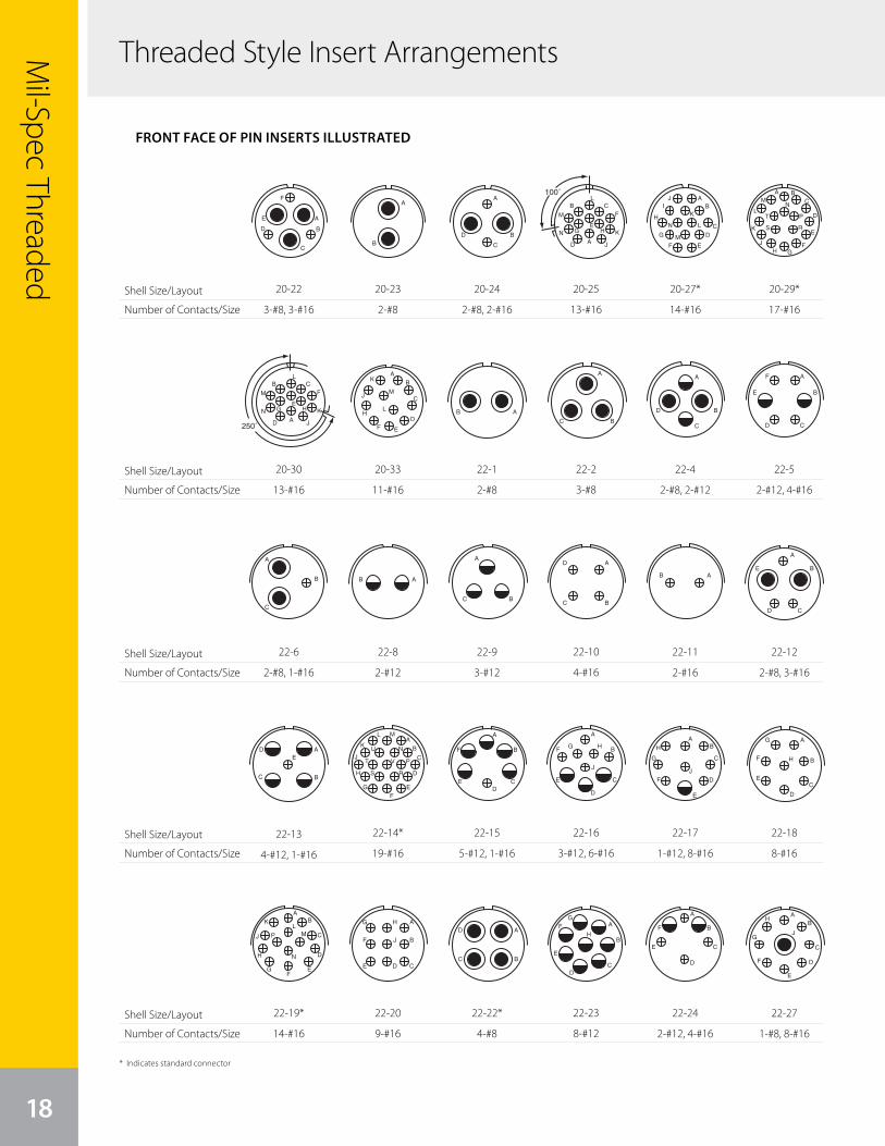
Threaded Style Insert Arrangements
18
Mil-Spec Threaded
Shell Size/Layout
Number of Contacts/Size
Shell Size/Layout
Number of Contacts/Size
Shell Size/Layout
Number of Contacts/Size
Shell Size/Layout
Number of Contacts/Size
Shell Size/Layout
Number of Contacts/Size29
front face of pin insert or rear face of socket insert illustrated
MS/Standardcontact arrangements
Insert Arrangement 20-20 20-21 20-22 20-23 20-24 20-25
Service Rating A A A A A Inst.
Number of Contacts 1 3 1 8 3 3 2 2 2 13
Contact Size 4 12 12 16 8 16 8 8 16 16
Insert Arrangement 20-27 20-29 20-30 20-33 22-1 22-2
Service Rating A A Inst. A D D
Number of Contacts 14 17 13 11 2 3
Contact Size 16 16 16 16 8 8
Insert Arrangement 22-4 22-5 22-6 22-7 22-8
Service Rating A D D E E
Number of Contacts 2 2 2 4 2 1 1 2
Contact Size 8 12 12 16 8 16 0 12
CONTACT LEGEND 16 12 8 4 0
250° Rotationof 20-11
100° Rotationof 20-11
A
B
C
DA
B
C
DE
F
G
H
I A
B
C
D
E
FA
B
A
B
C
D
AB
CD
EF
G
H
IJ
K
L
M
N
A BC
D
E
FGH
J
K
L
MN
PT
S R
AB
C
D
EF
K
H
JM
L AB
A
BC
A
B
C
D
A
B
CD
E
F A
B
C
AB
250˚A
B C
D
E
F
G H
J
K
L
M
N
100˚
A
B C
D
E
F
G H
J
K
L
M
N
20-22
3-#8, 3-#16
29
front face of pin insert or rear face of socket insert illustrated
MS/Standardcontact arrangements
Insert Arrangement 20-20 20-21 20-22 20-23 20-24 20-25
Service Rating A A A A A Inst.
Number of Contacts 1 3 1 8 3 3 2 2 2 13
Contact Size 4 12 12 16 8 16 8 8 16 16
Insert Arrangement 20-27 20-29 20-30 20-33 22-1 22-2
Service Rating A A Inst. A D D
Number of Contacts 14 17 13 11 2 3
Contact Size 16 16 16 16 8 8
Insert Arrangement 22-4 22-5 22-6 22-7 22-8
Service Rating A D D E E
Number of Contacts 2 2 2 4 2 1 1 2
Contact Size 8 12 12 16 8 16 0 12
CONTACT LEGEND 16 12 8 4 0
250° Rotationof 20-11
100° Rotationof 20-11
A
B
C
DA
B
C
DE
F
G
H
I A
B
C
D
E
FA
B
A
B
C
D
AB
CD
EF
G
H
IJ
K
L
M
N
A BC
D
E
FGH
J
K
L
MN
PT
S R
AB
C
D
EF
K
H
JM
L AB
A
BC
A
B
C
D
A
B
CD
E
F A
B
C
AB
250˚A
B C
D
E
F
G H
J
K
L
M
N
100˚
A
B C
D
E
F
G H
J
K
L
M
N
20-29*
17-#16
29
front face of pin insert or rear face of socket insert illustrated
MS/Standardcontact arrangements
Insert Arrangement 20-20 20-21 20-22 20-23 20-24 20-25
Service Rating A A A A A Inst.
Number of Contacts 1 3 1 8 3 3 2 2 2 13
Contact Size 4 12 12 16 8 16 8 8 16 16
Insert Arrangement 20-27 20-29 20-30 20-33 22-1 22-2
Service Rating A A Inst. A D D
Number of Contacts 14 17 13 11 2 3
Contact Size 16 16 16 16 8 8
Insert Arrangement 22-4 22-5 22-6 22-7 22-8
Service Rating A D D E E
Number of Contacts 2 2 2 4 2 1 1 2
Contact Size 8 12 12 16 8 16 0 12
CONTACT LEGEND 16 12 8 4 0
250° Rotationof 20-11
100° Rotationof 20-11
A
B
C
DA
B
C
DE
F
G
H
I A
B
C
D
E
FA
B
A
B
C
D
AB
CD
EF
G
H
IJ
K
L
M
N
A BC
D
E
FGH
J
K
L
MN
PT
S R
AB
C
D
EF
K
H
JM
L AB
A
BC
A
B
C
D
A
B
CD
E
F A
B
C
AB
250˚A
B C
D
E
F
G H
J
K
L
M
N
100˚
A
B C
D
E
F
G H
J
K
L
M
N
22-5
2-#12, 4-#16
30
front face of pin insert or rear face of socket insert illustrated
MS/Standardcontact arrangements
Insert Arrangement 22-9 22-10 22-11 22-12 22-13
Service Rating E E B D E = D; A, B, C, D = A
Number of Contacts 3 4 2 2 3 4 1
Contact Size 12 16 16 8 16 12 16
Insert Arrangement 22-14 22-15 22-16 22-17 22-18
Service Rating A D = E; A, B, C, E, F = A A A = D; Bal. = A A, B, F, G, H = D; C, D, E = A
Number of Contacts 19 5 1 3 6 1 8 8
Contact Size 16 12 16 12 16 12 16 16
Insert Arrangement 22-19 22-20 22-21 22-22 22-23
Service Rating A A A A H = D; Bal. = A
Number of Contacts 14 9 1 2 4 8
Contact Size 16 16 0 16 8 12
CONTACT LEGEND 16 12 8 4 0
A
BC
A
BC
D
AB
A
B
CD
E A
BC
DE
A
B
C
D
EF
G
H
J
K
L M
NU
V
RS
T P
A
B
E
F
CD
A
B
C
D
E
F G H
J
AB
C
D
E
F
G
H
J
A
B
C
D
E
F
G
H
AB
C
D
EF
G
H
J
KL
M
N
P
A
B
CDE
F
G H
J
A
B
C A
BC
DA
B
CD
E
FG
H
22-12
2-#8, 3-#16
30
front face of pin insert or rear face of socket insert illustrated
MS/Standardcontact arrangements
Insert Arrangement 22-9 22-10 22-11 22-12 22-13
Service Rating E E B D E = D; A, B, C, D = A
Number of Contacts 3 4 2 2 3 4 1
Contact Size 12 16 16 8 16 12 16
Insert Arrangement 22-14 22-15 22-16 22-17 22-18
Service Rating A D = E; A, B, C, E, F = A A A = D; Bal. = A A, B, F, G, H = D; C, D, E = A
Number of Contacts 19 5 1 3 6 1 8 8
Contact Size 16 12 16 12 16 12 16 16
Insert Arrangement 22-19 22-20 22-21 22-22 22-23
Service Rating A A A A H = D; Bal. = A
Number of Contacts 14 9 1 2 4 8
Contact Size 16 16 0 16 8 12
CONTACT LEGEND 16 12 8 4 0
A
BC
A
BC
D
AB
A
B
CD
E A
BC
DE
A
B
C
D
EF
G
H
J
K
L M
NU
V
RS
T P
A
B
E
F
CD
A
B
C
D
E
F G H
J
AB
C
D
E
F
G
H
J
A
B
C
D
E
F
G
H
AB
C
D
EF
G
H
J
KL
M
N
P
A
B
CDE
F
G H
J
A
B
C A
BC
DA
B
CD
E
FG
H
22-18
8-#16
29
front face of pin insert or rear face of socket insert illustrated
MS/Standardcontact arrangements
Insert Arrangement 20-20 20-21 20-22 20-23 20-24 20-25
Service Rating A A A A A Inst.
Number of Contacts 1 3 1 8 3 3 2 2 2 13
Contact Size 4 12 12 16 8 16 8 8 16 16
Insert Arrangement 20-27 20-29 20-30 20-33 22-1 22-2
Service Rating A A Inst. A D D
Number of Contacts 14 17 13 11 2 3
Contact Size 16 16 16 16 8 8
Insert Arrangement 22-4 22-5 22-6 22-7 22-8
Service Rating A D D E E
Number of Contacts 2 2 2 4 2 1 1 2
Contact Size 8 12 12 16 8 16 0 12
CONTACT LEGEND 16 12 8 4 0
250° Rotationof 20-11
100° Rotationof 20-11
A
B
C
DA
B
C
DE
F
G
H
I A
B
C
D
E
FA
B
A
B
C
D
AB
CD
EF
G
H
IJ
K
L
M
N
A BC
D
E
FGH
J
K
L
MN
PT
S R
AB
C
D
EF
K
H
JM
L AB
A
BC
A
B
C
D
A
B
CD
E
F A
B
C
AB
250˚A
B C
D
E
F
G H
J
K
L
M
N
100˚
A
B C
D
E
F
G H
J
K
L
M
N
20-23
2-#8
29
front face of pin insert or rear face of socket insert illustrated
MS/Standardcontact arrangements
Insert Arrangement 20-20 20-21 20-22 20-23 20-24 20-25
Service Rating A A A A A Inst.
Number of Contacts 1 3 1 8 3 3 2 2 2 13
Contact Size 4 12 12 16 8 16 8 8 16 16
Insert Arrangement 20-27 20-29 20-30 20-33 22-1 22-2
Service Rating A A Inst. A D D
Number of Contacts 14 17 13 11 2 3
Contact Size 16 16 16 16 8 8
Insert Arrangement 22-4 22-5 22-6 22-7 22-8
Service Rating A D D E E
Number of Contacts 2 2 2 4 2 1 1 2
Contact Size 8 12 12 16 8 16 0 12
CONTACT LEGEND 16 12 8 4 0
250° Rotationof 20-11
100° Rotationof 20-11
A
B
C
DA
B
C
DE
F
G
H
I A
B
C
D
E
FA
B
A
B
C
D
AB
CD
EF
G
H
IJ
K
L
M
N
A BC
D
E
FGH
J
K
L
MN
PT
S R
AB
C
D
EF
K
H
JM
L AB
A
BC
A
B
C
D
A
B
CD
E
F A
B
C
AB
250˚A
B C
D
E
F
G H
J
K
L
M
N
100˚
A
B C
D
E
F
G H
J
K
L
M
N
20-30
13-#16
29
front face of pin insert or rear face of socket insert illustrated
MS/Standardcontact arrangements
Insert Arrangement 20-20 20-21 20-22 20-23 20-24 20-25
Service Rating A A A A A Inst.
Number of Contacts 1 3 1 8 3 3 2 2 2 13
Contact Size 4 12 12 16 8 16 8 8 16 16
Insert Arrangement 20-27 20-29 20-30 20-33 22-1 22-2
Service Rating A A Inst. A D D
Number of Contacts 14 17 13 11 2 3
Contact Size 16 16 16 16 8 8
Insert Arrangement 22-4 22-5 22-6 22-7 22-8
Service Rating A D D E E
Number of Contacts 2 2 2 4 2 1 1 2
Contact Size 8 12 12 16 8 16 0 12
CONTACT LEGEND 16 12 8 4 0
250° Rotationof 20-11
100° Rotationof 20-11
A
B
C
DA
B
C
DE
F
G
H
I A
B
C
D
E
FA
B
A
B
C
D
AB
CD
EF
G
H
IJ
K
L
M
N
A BC
D
E
FGH
J
K
L
MN
PT
S R
AB
C
D
EF
K
H
JM
L AB
A
BC
A
B
C
D
A
B
CD
E
F A
B
C
AB
250˚A
B C
D
E
F
G H
J
K
L
M
N
100˚
A
B C
D
E
F
G H
J
K
L
M
N
22-6
2-#8, 1-#16
30
front face of pin insert or rear face of socket insert illustrated
MS/Standardcontact arrangements
Insert Arrangement 22-9 22-10 22-11 22-12 22-13
Service Rating E E B D E = D; A, B, C, D = A
Number of Contacts 3 4 2 2 3 4 1
Contact Size 12 16 16 8 16 12 16
Insert Arrangement 22-14 22-15 22-16 22-17 22-18
Service Rating A D = E; A, B, C, E, F = A A A = D; Bal. = A A, B, F, G, H = D; C, D, E = A
Number of Contacts 19 5 1 3 6 1 8 8
Contact Size 16 12 16 12 16 12 16 16
Insert Arrangement 22-19 22-20 22-21 22-22 22-23
Service Rating A A A A H = D; Bal. = A
Number of Contacts 14 9 1 2 4 8
Contact Size 16 16 0 16 8 12
CONTACT LEGEND 16 12 8 4 0
A
BC
A
BC
D
AB
A
B
CD
E A
BC
DE
A
B
C
D
EF
G
H
J
K
L M
NU
V
RS
T P
A
B
E
F
CD
A
B
C
D
E
F G H
J
AB
C
D
E
F
G
H
J
A
B
C
D
E
F
G
H
AB
C
D
EF
G
H
J
KL
M
N
P
A
B
CDE
F
G H
J
A
B
C A
BC
DA
B
CD
E
FG
H
22-13
4-#12, 1-#16
30
front face of pin insert or rear face of socket insert illustrated
MS/Standardcontact arrangements
Insert Arrangement 22-9 22-10 22-11 22-12 22-13
Service Rating E E B D E = D; A, B, C, D = A
Number of Contacts 3 4 2 2 3 4 1
Contact Size 12 16 16 8 16 12 16
Insert Arrangement 22-14 22-15 22-16 22-17 22-18
Service Rating A D = E; A, B, C, E, F = A A A = D; Bal. = A A, B, F, G, H = D; C, D, E = A
Number of Contacts 19 5 1 3 6 1 8 8
Contact Size 16 12 16 12 16 12 16 16
Insert Arrangement 22-19 22-20 22-21 22-22 22-23
Service Rating A A A A H = D; Bal. = A
Number of Contacts 14 9 1 2 4 8
Contact Size 16 16 0 16 8 12
CONTACT LEGEND 16 12 8 4 0
A
BC
A
BC
D
AB
A
B
CD
E A
BC
DE
A
B
C
D
EF
G
H
J
K
L M
NU
V
RS
T P
A
B
E
F
CD
A
B
C
D
E
F G H
J
AB
C
D
E
F
G
H
J
A
B
C
D
E
F
G
H
AB
C
D
EF
G
H
J
KL
M
N
P
A
B
CDE
F
G H
J
A
B
C A
BC
DA
B
CD
E
FG
H
22-19*
14-#1629
front face of pin insert or rear face of socket insert illustrated
MS/Standardcontact arrangements
Insert Arrangement 20-20 20-21 20-22 20-23 20-24 20-25
Service Rating A A A A A Inst.
Number of Contacts 1 3 1 8 3 3 2 2 2 13
Contact Size 4 12 12 16 8 16 8 8 16 16
Insert Arrangement 20-27 20-29 20-30 20-33 22-1 22-2
Service Rating A A Inst. A D D
Number of Contacts 14 17 13 11 2 3
Contact Size 16 16 16 16 8 8
Insert Arrangement 22-4 22-5 22-6 22-7 22-8
Service Rating A D D E E
Number of Contacts 2 2 2 4 2 1 1 2
Contact Size 8 12 12 16 8 16 0 12
CONTACT LEGEND 16 12 8 4 0
250° Rotationof 20-11
100° Rotationof 20-11
A
B
C
DA
B
C
DE
F
G
H
I A
B
C
D
E
FA
B
A
B
C
D
AB
CD
EF
G
H
IJ
K
L
M
N
A BC
D
E
FGH
J
K
L
MN
PT
S R
AB
C
D
EF
K
H
JM
L AB
A
BC
A
B
C
D
A
B
CD
E
F A
B
C
AB
250˚A
B C
D
E
F
G H
J
K
L
M
N
100˚
A
B C
D
E
F
G H
J
K
L
M
N
20-24
2-#8, 2-#16
29
front face of pin insert or rear face of socket insert illustrated
MS/Standardcontact arrangements
Insert Arrangement 20-20 20-21 20-22 20-23 20-24 20-25
Service Rating A A A A A Inst.
Number of Contacts 1 3 1 8 3 3 2 2 2 13
Contact Size 4 12 12 16 8 16 8 8 16 16
Insert Arrangement 20-27 20-29 20-30 20-33 22-1 22-2
Service Rating A A Inst. A D D
Number of Contacts 14 17 13 11 2 3
Contact Size 16 16 16 16 8 8
Insert Arrangement 22-4 22-5 22-6 22-7 22-8
Service Rating A D D E E
Number of Contacts 2 2 2 4 2 1 1 2
Contact Size 8 12 12 16 8 16 0 12
CONTACT LEGEND 16 12 8 4 0
250° Rotationof 20-11
100° Rotationof 20-11
A
B
C
DA
B
C
DE
F
G
H
I A
B
C
D
E
FA
B
A
B
C
D
AB
CD
EF
G
H
IJ
K
L
M
N
A BC
D
E
FGH
J
K
L
MN
PT
S R
AB
C
D
EF
K
H
JM
L AB
A
BC
A
B
C
D
A
B
CD
E
F A
B
C
AB
250˚A
B C
D
E
F
G H
J
K
L
M
N
100˚
A
B C
D
E
F
G H
J
K
L
M
N
20-33
11-#16
29
front face of pin insert or rear face of socket insert illustrated
MS/Standardcontact arrangements
Insert Arrangement 20-20 20-21 20-22 20-23 20-24 20-25
Service Rating A A A A A Inst.
Number of Contacts 1 3 1 8 3 3 2 2 2 13
Contact Size 4 12 12 16 8 16 8 8 16 16
Insert Arrangement 20-27 20-29 20-30 20-33 22-1 22-2
Service Rating A A Inst. A D D
Number of Contacts 14 17 13 11 2 3
Contact Size 16 16 16 16 8 8
Insert Arrangement 22-4 22-5 22-6 22-7 22-8
Service Rating A D D E E
Number of Contacts 2 2 2 4 2 1 1 2
Contact Size 8 12 12 16 8 16 0 12
CONTACT LEGEND 16 12 8 4 0
250° Rotationof 20-11
100° Rotationof 20-11
A
B
C
DA
B
C
DE
F
G
H
I A
B
C
D
E
FA
B
A
B
C
D
AB
CD
EF
G
H
IJ
K
L
M
N
A BC
D
E
FGH
J
K
L
MN
PT
S R
AB
C
D
EF
K
H
JM
L AB
A
BC
A
B
C
D
A
B
CD
E
F A
B
C
AB
250˚A
B C
D
E
F
G H
J
K
L
M
N
100˚
A
B C
D
E
F
G H
J
K
L
M
N
22-8
2-#12
30
front face of pin insert or rear face of socket insert illustrated
MS/Standardcontact arrangements
Insert Arrangement 22-9 22-10 22-11 22-12 22-13
Service Rating E E B D E = D; A, B, C, D = A
Number of Contacts 3 4 2 2 3 4 1
Contact Size 12 16 16 8 16 12 16
Insert Arrangement 22-14 22-15 22-16 22-17 22-18
Service Rating A D = E; A, B, C, E, F = A A A = D; Bal. = A A, B, F, G, H = D; C, D, E = A
Number of Contacts 19 5 1 3 6 1 8 8
Contact Size 16 12 16 12 16 12 16 16
Insert Arrangement 22-19 22-20 22-21 22-22 22-23
Service Rating A A A A H = D; Bal. = A
Number of Contacts 14 9 1 2 4 8
Contact Size 16 16 0 16 8 12
CONTACT LEGEND 16 12 8 4 0
A
BC
A
BC
D
AB
A
B
CD
E A
BC
DE
A
B
C
D
EF
G
H
J
K
L M
NU
V
RS
T P
A
B
E
F
CD
A
B
C
D
E
F G H
J
AB
C
D
E
F
G
H
J
A
B
C
D
E
F
G
H
AB
C
D
EF
G
H
J
KL
M
N
P
A
B
CDE
F
G H
J
A
B
C A
BC
DA
B
CD
E
FG
H
22-14*
19-#16
30
front face of pin insert or rear face of socket insert illustrated
MS/Standardcontact arrangements
Insert Arrangement 22-9 22-10 22-11 22-12 22-13
Service Rating E E B D E = D; A, B, C, D = A
Number of Contacts 3 4 2 2 3 4 1
Contact Size 12 16 16 8 16 12 16
Insert Arrangement 22-14 22-15 22-16 22-17 22-18
Service Rating A D = E; A, B, C, E, F = A A A = D; Bal. = A A, B, F, G, H = D; C, D, E = A
Number of Contacts 19 5 1 3 6 1 8 8
Contact Size 16 12 16 12 16 12 16 16
Insert Arrangement 22-19 22-20 22-21 22-22 22-23
Service Rating A A A A H = D; Bal. = A
Number of Contacts 14 9 1 2 4 8
Contact Size 16 16 0 16 8 12
CONTACT LEGEND 16 12 8 4 0
A
BC
A
BC
D
AB
A
B
CD
E A
BC
DE
A
B
C
D
EF
G
H
J
K
L M
NU
V
RS
T P
A
B
E
F
CD
A
B
C
D
E
F G H
J
AB
C
D
E
F
G
H
J
A
B
C
D
E
F
G
H
AB
C
D
EF
G
H
J
KL
M
N
P
A
B
CDE
F
G H
J
A
B
C A
BC
DA
B
CD
E
FG
H
22-20
9-#16
29
front face of pin insert or rear face of socket insert illustrated
MS/Standardcontact arrangements
Insert Arrangement 20-20 20-21 20-22 20-23 20-24 20-25
Service Rating A A A A A Inst.
Number of Contacts 1 3 1 8 3 3 2 2 2 13
Contact Size 4 12 12 16 8 16 8 8 16 16
Insert Arrangement 20-27 20-29 20-30 20-33 22-1 22-2
Service Rating A A Inst. A D D
Number of Contacts 14 17 13 11 2 3
Contact Size 16 16 16 16 8 8
Insert Arrangement 22-4 22-5 22-6 22-7 22-8
Service Rating A D D E E
Number of Contacts 2 2 2 4 2 1 1 2
Contact Size 8 12 12 16 8 16 0 12
CONTACT LEGEND 16 12 8 4 0
250° Rotationof 20-11
100° Rotationof 20-11
A
B
C
DA
B
C
DE
F
G
H
I A
B
C
D
E
FA
B
A
B
C
D
AB
CD
EF
G
H
IJ
K
L
M
N
A BC
D
E
FGH
J
K
L
MN
PT
S R
AB
C
D
EF
K
H
JM
L AB
A
BC
A
B
C
D
A
B
CD
E
F A
B
C
AB
250˚A
B C
D
E
F
G H
J
K
L
M
N
100˚
A
B C
D
E
F
G H
J
K
L
M
N
22-1
2-#8
30
front face of pin insert or rear face of socket insert illustrated
MS/Standardcontact arrangements
Insert Arrangement 22-9 22-10 22-11 22-12 22-13
Service Rating E E B D E = D; A, B, C, D = A
Number of Contacts 3 4 2 2 3 4 1
Contact Size 12 16 16 8 16 12 16
Insert Arrangement 22-14 22-15 22-16 22-17 22-18
Service Rating A D = E; A, B, C, E, F = A A A = D; Bal. = A A, B, F, G, H = D; C, D, E = A
Number of Contacts 19 5 1 3 6 1 8 8
Contact Size 16 12 16 12 16 12 16 16
Insert Arrangement 22-19 22-20 22-21 22-22 22-23
Service Rating A A A A H = D; Bal. = A
Number of Contacts 14 9 1 2 4 8
Contact Size 16 16 0 16 8 12
CONTACT LEGEND 16 12 8 4 0
A
BC
A
BC
D
AB
A
B
CD
E A
BC
DE
A
B
C
D
EF
G
H
J
K
L M
NU
V
RS
T P
A
B
E
F
CD
A
B
C
D
E
F G H
J
AB
C
D
E
F
G
H
J
A
B
C
D
E
F
G
H
AB
C
D
EF
G
H
J
KL
M
N
P
A
B
CDE
F
G H
J
A
B
C A
BC
DA
B
CD
E
FG
H
22-9
3-#12
30
front face of pin insert or rear face of socket insert illustrated
MS/Standardcontact arrangements
Insert Arrangement 22-9 22-10 22-11 22-12 22-13
Service Rating E E B D E = D; A, B, C, D = A
Number of Contacts 3 4 2 2 3 4 1
Contact Size 12 16 16 8 16 12 16
Insert Arrangement 22-14 22-15 22-16 22-17 22-18
Service Rating A D = E; A, B, C, E, F = A A A = D; Bal. = A A, B, F, G, H = D; C, D, E = A
Number of Contacts 19 5 1 3 6 1 8 8
Contact Size 16 12 16 12 16 12 16 16
Insert Arrangement 22-19 22-20 22-21 22-22 22-23
Service Rating A A A A H = D; Bal. = A
Number of Contacts 14 9 1 2 4 8
Contact Size 16 16 0 16 8 12
CONTACT LEGEND 16 12 8 4 0
A
BC
A
BC
D
AB
A
B
CD
E A
BC
DE
A
B
C
D
EF
G
H
J
K
L M
NU
V
RS
T P
A
B
E
F
CD
A
B
C
D
E
F G H
J
AB
C
D
E
F
G
H
J
A
B
C
D
E
F
G
H
AB
C
D
EF
G
H
J
KL
M
N
P
A
B
CDE
F
G H
J
A
B
C A
BC
DA
B
CD
E
FG
H
22-15
5-#12, 1-#16
30
front face of pin insert or rear face of socket insert illustrated
MS/Standardcontact arrangements
Insert Arrangement 22-9 22-10 22-11 22-12 22-13
Service Rating E E B D E = D; A, B, C, D = A
Number of Contacts 3 4 2 2 3 4 1
Contact Size 12 16 16 8 16 12 16
Insert Arrangement 22-14 22-15 22-16 22-17 22-18
Service Rating A D = E; A, B, C, E, F = A A A = D; Bal. = A A, B, F, G, H = D; C, D, E = A
Number of Contacts 19 5 1 3 6 1 8 8
Contact Size 16 12 16 12 16 12 16 16
Insert Arrangement 22-19 22-20 22-21 22-22 22-23
Service Rating A A A A H = D; Bal. = A
Number of Contacts 14 9 1 2 4 8
Contact Size 16 16 0 16 8 12
CONTACT LEGEND 16 12 8 4 0
A
BC
A
BC
D
AB
A
B
CD
E A
BC
DE
A
B
C
D
EF
G
H
J
K
L M
NU
V
RS
T P
A
B
E
F
CD
A
B
C
D
E
F G H
J
AB
C
D
E
F
G
H
J
A
B
C
D
E
F
G
H
AB
C
D
EF
G
H
J
KL
M
N
P
A
B
CDE
F
G H
J
A
B
C A
BC
DA
B
CD
E
FG
H
22-22*
4-#829
front face of pin insert or rear face of socket insert illustrated
MS/Standardcontact arrangements
Insert Arrangement 20-20 20-21 20-22 20-23 20-24 20-25
Service Rating A A A A A Inst.
Number of Contacts 1 3 1 8 3 3 2 2 2 13
Contact Size 4 12 12 16 8 16 8 8 16 16
Insert Arrangement 20-27 20-29 20-30 20-33 22-1 22-2
Service Rating A A Inst. A D D
Number of Contacts 14 17 13 11 2 3
Contact Size 16 16 16 16 8 8
Insert Arrangement 22-4 22-5 22-6 22-7 22-8
Service Rating A D D E E
Number of Contacts 2 2 2 4 2 1 1 2
Contact Size 8 12 12 16 8 16 0 12
CONTACT LEGEND 16 12 8 4 0
250° Rotationof 20-11
100° Rotationof 20-11
A
B
C
DA
B
C
DE
F
G
H
I A
B
C
D
E
FA
B
A
B
C
D
AB
CD
EF
G
H
IJ
K
L
M
N
A BC
D
E
FGH
J
K
L
MN
PT
S R
AB
C
D
EF
K
H
JM
L AB
A
BC
A
B
C
D
A
B
CD
E
F A
B
C
AB
250˚A
B C
D
E
F
G H
J
K
L
M
N
100˚
A
B C
D
E
F
G H
J
K
L
M
N
20-25
13-#16
29
front face of pin insert or rear face of socket insert illustrated
MS/Standardcontact arrangements
Insert Arrangement 20-20 20-21 20-22 20-23 20-24 20-25
Service Rating A A A A A Inst.
Number of Contacts 1 3 1 8 3 3 2 2 2 13
Contact Size 4 12 12 16 8 16 8 8 16 16
Insert Arrangement 20-27 20-29 20-30 20-33 22-1 22-2
Service Rating A A Inst. A D D
Number of Contacts 14 17 13 11 2 3
Contact Size 16 16 16 16 8 8
Insert Arrangement 22-4 22-5 22-6 22-7 22-8
Service Rating A D D E E
Number of Contacts 2 2 2 4 2 1 1 2
Contact Size 8 12 12 16 8 16 0 12
CONTACT LEGEND 16 12 8 4 0
250° Rotationof 20-11
100° Rotationof 20-11
A
B
C
DA
B
C
DE
F
G
H
I A
B
C
D
E
FA
B
A
B
C
D
AB
CD
EF
G
H
IJ
K
L
M
N
A BC
D
E
FGH
J
K
L
MN
PT
S R
AB
C
D
EF
K
H
JM
L AB
A
BC
A
B
C
D
A
B
CD
E
F A
B
C
AB
250˚A
B C
D
E
F
G H
J
K
L
M
N
100˚
A
B C
D
E
F
G H
J
K
L
M
N
22-2
3-#8
30
front face of pin insert or rear face of socket insert illustrated
MS/Standardcontact arrangements
Insert Arrangement 22-9 22-10 22-11 22-12 22-13
Service Rating E E B D E = D; A, B, C, D = A
Number of Contacts 3 4 2 2 3 4 1
Contact Size 12 16 16 8 16 12 16
Insert Arrangement 22-14 22-15 22-16 22-17 22-18
Service Rating A D = E; A, B, C, E, F = A A A = D; Bal. = A A, B, F, G, H = D; C, D, E = A
Number of Contacts 19 5 1 3 6 1 8 8
Contact Size 16 12 16 12 16 12 16 16
Insert Arrangement 22-19 22-20 22-21 22-22 22-23
Service Rating A A A A H = D; Bal. = A
Number of Contacts 14 9 1 2 4 8
Contact Size 16 16 0 16 8 12
CONTACT LEGEND 16 12 8 4 0
A
BC
A
BC
D
AB
A
B
CD
E A
BC
DE
A
B
C
D
EF
G
H
J
K
L M
NU
V
RS
T P
A
B
E
F
CD
A
B
C
D
E
F G H
J
AB
C
D
E
F
G
H
J
A
B
C
D
E
F
G
H
AB
C
D
EF
G
H
J
KL
M
N
P
A
B
CDE
F
G H
J
A
B
C A
BC
DA
B
CD
E
FG
H
22-10
4-#16
30
front face of pin insert or rear face of socket insert illustrated
MS/Standardcontact arrangements
Insert Arrangement 22-9 22-10 22-11 22-12 22-13
Service Rating E E B D E = D; A, B, C, D = A
Number of Contacts 3 4 2 2 3 4 1
Contact Size 12 16 16 8 16 12 16
Insert Arrangement 22-14 22-15 22-16 22-17 22-18
Service Rating A D = E; A, B, C, E, F = A A A = D; Bal. = A A, B, F, G, H = D; C, D, E = A
Number of Contacts 19 5 1 3 6 1 8 8
Contact Size 16 12 16 12 16 12 16 16
Insert Arrangement 22-19 22-20 22-21 22-22 22-23
Service Rating A A A A H = D; Bal. = A
Number of Contacts 14 9 1 2 4 8
Contact Size 16 16 0 16 8 12
CONTACT LEGEND 16 12 8 4 0
A
BC
A
BC
D
AB
A
B
CD
E A
BC
DE
A
B
C
D
EF
G
H
J
K
L M
NU
V
RS
T P
A
B
E
F
CD
A
B
C
D
E
F G H
J
AB
C
D
E
F
G
H
J
A
B
C
D
E
F
G
H
AB
C
D
EF
G
H
J
KL
M
N
P
A
B
CDE
F
G H
J
A
B
C A
BC
DA
B
CD
E
FG
H
22-16
3-#12, 6-#16
30
front face of pin insert or rear face of socket insert illustrated
MS/Standardcontact arrangements
Insert Arrangement 22-9 22-10 22-11 22-12 22-13
Service Rating E E B D E = D; A, B, C, D = A
Number of Contacts 3 4 2 2 3 4 1
Contact Size 12 16 16 8 16 12 16
Insert Arrangement 22-14 22-15 22-16 22-17 22-18
Service Rating A D = E; A, B, C, E, F = A A A = D; Bal. = A A, B, F, G, H = D; C, D, E = A
Number of Contacts 19 5 1 3 6 1 8 8
Contact Size 16 12 16 12 16 12 16 16
Insert Arrangement 22-19 22-20 22-21 22-22 22-23
Service Rating A A A A H = D; Bal. = A
Number of Contacts 14 9 1 2 4 8
Contact Size 16 16 0 16 8 12
CONTACT LEGEND 16 12 8 4 0
A
BC
A
BC
D
AB
A
B
CD
E A
BC
DE
A
B
C
D
EF
G
H
J
K
L M
NU
V
RS
T P
A
B
E
F
CD
A
B
C
D
E
F G H
J
AB
C
D
E
F
G
H
J
A
B
C
D
E
F
G
H
AB
C
D
EF
G
H
J
KL
M
N
P
A
B
CDE
F
G H
J
A
B
C A
BC
DA
B
CD
E
FG
H
22-23
8-#12
29
front face of pin insert or rear face of socket insert illustrated
MS/Standardcontact arrangements
Insert Arrangement 20-20 20-21 20-22 20-23 20-24 20-25
Service Rating A A A A A Inst.
Number of Contacts 1 3 1 8 3 3 2 2 2 13
Contact Size 4 12 12 16 8 16 8 8 16 16
Insert Arrangement 20-27 20-29 20-30 20-33 22-1 22-2
Service Rating A A Inst. A D D
Number of Contacts 14 17 13 11 2 3
Contact Size 16 16 16 16 8 8
Insert Arrangement 22-4 22-5 22-6 22-7 22-8
Service Rating A D D E E
Number of Contacts 2 2 2 4 2 1 1 2
Contact Size 8 12 12 16 8 16 0 12
CONTACT LEGEND 16 12 8 4 0
250° Rotationof 20-11
100° Rotationof 20-11
A
B
C
DA
B
C
DE
F
G
H
I A
B
C
D
E
FA
B
A
B
C
D
AB
CD
EF
G
H
IJ
K
L
M
N
A BC
D
E
FGH
J
K
L
MN
PT
S R
AB
C
D
EF
K
H
JM
L AB
A
BC
A
B
C
D
A
B
CD
E
F A
B
C
AB
250˚A
B C
D
E
F
G H
J
K
L
M
N
100˚
A
B C
D
E
F
G H
J
K
L
M
N
20-27*
14-#16
29
front face of pin insert or rear face of socket insert illustrated
MS/Standardcontact arrangements
Insert Arrangement 20-20 20-21 20-22 20-23 20-24 20-25
Service Rating A A A A A Inst.
Number of Contacts 1 3 1 8 3 3 2 2 2 13
Contact Size 4 12 12 16 8 16 8 8 16 16
Insert Arrangement 20-27 20-29 20-30 20-33 22-1 22-2
Service Rating A A Inst. A D D
Number of Contacts 14 17 13 11 2 3
Contact Size 16 16 16 16 8 8
Insert Arrangement 22-4 22-5 22-6 22-7 22-8
Service Rating A D D E E
Number of Contacts 2 2 2 4 2 1 1 2
Contact Size 8 12 12 16 8 16 0 12
CONTACT LEGEND 16 12 8 4 0
250° Rotationof 20-11
100° Rotationof 20-11
A
B
C
DA
B
C
DE
F
G
H
I A
B
C
D
E
FA
B
A
B
C
D
AB
CD
EF
G
H
IJ
K
L
M
N
A BC
D
E
FGH
J
K
L
MN
PT
S R
AB
C
D
EF
K
H
JM
L AB
A
BC
A
B
C
D
A
B
CD
E
F A
B
C
AB
250˚A
B C
D
E
F
G H
J
K
L
M
N
100˚
A
B C
D
E
F
G H
J
K
L
M
N
22-4
2-#8, 2-#12
30
front face of pin insert or rear face of socket insert illustrated
MS/Standardcontact arrangements
Insert Arrangement 22-9 22-10 22-11 22-12 22-13
Service Rating E E B D E = D; A, B, C, D = A
Number of Contacts 3 4 2 2 3 4 1
Contact Size 12 16 16 8 16 12 16
Insert Arrangement 22-14 22-15 22-16 22-17 22-18
Service Rating A D = E; A, B, C, E, F = A A A = D; Bal. = A A, B, F, G, H = D; C, D, E = A
Number of Contacts 19 5 1 3 6 1 8 8
Contact Size 16 12 16 12 16 12 16 16
Insert Arrangement 22-19 22-20 22-21 22-22 22-23
Service Rating A A A A H = D; Bal. = A
Number of Contacts 14 9 1 2 4 8
Contact Size 16 16 0 16 8 12
CONTACT LEGEND 16 12 8 4 0
A
BC
A
BC
D
AB
A
B
CD
E A
BC
DE
A
B
C
D
EF
G
H
J
K
L M
NU
V
RS
T P
A
B
E
F
CD
A
B
C
D
E
F G H
J
AB
C
D
E
F
G
H
J
A
B
C
D
E
F
G
H
AB
C
D
EF
G
H
J
KL
M
N
P
A
B
CDE
F
G H
J
A
B
C A
BC
DA
B
CD
E
FG
H
22-11
2-#16
30
front face of pin insert or rear face of socket insert illustrated
MS/Standardcontact arrangements
Insert Arrangement 22-9 22-10 22-11 22-12 22-13
Service Rating E E B D E = D; A, B, C, D = A
Number of Contacts 3 4 2 2 3 4 1
Contact Size 12 16 16 8 16 12 16
Insert Arrangement 22-14 22-15 22-16 22-17 22-18
Service Rating A D = E; A, B, C, E, F = A A A = D; Bal. = A A, B, F, G, H = D; C, D, E = A
Number of Contacts 19 5 1 3 6 1 8 8
Contact Size 16 12 16 12 16 12 16 16
Insert Arrangement 22-19 22-20 22-21 22-22 22-23
Service Rating A A A A H = D; Bal. = A
Number of Contacts 14 9 1 2 4 8
Contact Size 16 16 0 16 8 12
CONTACT LEGEND 16 12 8 4 0
A
BC
A
BC
D
AB
A
B
CD
E A
BC
DE
A
B
C
D
EF
G
H
J
K
L M
NU
V
RS
T P
A
B
E
F
CD
A
B
C
D
E
F G H
J
AB
C
D
E
F
G
H
J
A
B
C
D
E
F
G
H
AB
C
D
EF
G
H
J
KL
M
N
P
A
B
CDE
F
G H
J
A
B
C A
BC
DA
B
CD
E
FG
H
22-17
1-#12, 8-#16
31
A
B
C
D
E
F
G
H
front face of pin insert or rear face of socket insert illustrated
MS/Standardcontact arrangements
Insert Arrangement 22-24 22-27 22-28 22-33 22-36
Service Rating C, D, E = D; A, B, F = A J = D; Bal. = A A A, B, C, D = D; E, F, G = A H = D; Bal. = A*
Number of Contacts 2 4 1 8 7 7 8
Contact Size 12 16 8 16 12 16 12
Insert Arrangement 22-34 24-2 24-3 24-5 24-6
Service Rating D D D A A, G, H = D; Bal. = A
Number of Contacts 3 2 7 2 5 16 8
Contact Size 12 16 12 12 16 16 12
Insert Arrangement 24-7 24-9 24-10 24-11 24-12
Service Rating A A A A A
Number of Contacts 2 14 2 7 3 6 2 3
Contact Size 12 16 4 8 8 12 4 12
CONTACT LEGEND 16 12 8 4 0
A
B
C
D
E
F
AB
C
D
E
F
G
H
J
A
B
C
E
F
G
D
A
BCE
FG
D
A
BC
DE
A
B
CD
E
F
G
A
B
C
E
F
G
D
A BC
D EF G H
J KL M N
PS
R
AB
C
D
E
F
G
H
AB
C
D
E
FG
H
J
KL
M
NP
I O
AB
A
B
CD
E
FG
A B C
D E F
G
H
I
A
B
C
D
E
* A, C, E, G = IronB, D, F, H = Constantan
22-24
2-#12, 4-#16
31
A
B
C
D
E
F
G
H
front face of pin insert or rear face of socket insert illustrated
MS/Standardcontact arrangements
Insert Arrangement 22-24 22-27 22-28 22-33 22-36
Service Rating C, D, E = D; A, B, F = A J = D; Bal. = A A A, B, C, D = D; E, F, G = A H = D; Bal. = A*
Number of Contacts 2 4 1 8 7 7 8
Contact Size 12 16 8 16 12 16 12
Insert Arrangement 22-34 24-2 24-3 24-5 24-6
Service Rating D D D A A, G, H = D; Bal. = A
Number of Contacts 3 2 7 2 5 16 8
Contact Size 12 16 12 12 16 16 12
Insert Arrangement 24-7 24-9 24-10 24-11 24-12
Service Rating A A A A A
Number of Contacts 2 14 2 7 3 6 2 3
Contact Size 12 16 4 8 8 12 4 12
CONTACT LEGEND 16 12 8 4 0
A
B
C
D
E
F
AB
C
D
E
F
G
H
J
A
B
C
E
F
G
D
A
BCE
FG
D
A
BC
DE
A
B
CD
E
F
G
A
B
C
E
F
G
D
A BC
D EF G H
J KL M N
PS
R
AB
C
D
E
F
G
H
AB
C
D
E
FG
H
J
KL
M
NP
I O
AB
A
B
CD
E
FG
A B C
D E F
G
H
I
A
B
C
D
E
* A, C, E, G = IronB, D, F, H = Constantan
22-27
1-#8, 8-#16
* Indicates standard connector
FRONT FACE OF PIN INSERTS ILLUSTRATED

For more information call Turck at 1-800-987-6543 or visit our website at www.turck.us
Threaded Style Insert Arrangements
19
Mil-Spec Threaded
Shell Size/Layout
Number of Contacts/Size
Shell Size/Layout
Number of Contacts/Size
Shell Size/Layout
Number of Contacts/Size
32
front face of pin insert or rear face of socket insert illustrated
MS/Standardcontact arrangements
Insert Arrangement 24-16 24-17 24-20 24-21 24-22
Service Rating A, B, F, G = D; C, D, E, = A D D D D
Number of Contacts 1 3 3 2 3 2 9 1 9 4
Contact Size 8 12 16 12 16 12 16 8 16 8
Insert Arrangement 24-27 24-28 28-1 28-2 28-3
Service Rating E Inst. A, J, E = D; Bal. = A D E
Number of Contacts 7 24 3 6 2 12 3
Contact Size 16 16 8 12 12 16 8
Insert Arrangement 28-4 28-5 28-6 28-7
Service Rating G, P, S = E; Bal. = D D D D
Number of Contacts 2 7 2 1 2 3 2
Contact Size 12 16 4 12 16 4 4
CONTACT LEGEND 16 12 8 4 0
AB
C
D
E
AB
C
D
EF
G
H
J
K L
AB
C
D
E
F
G
H
J K
A
BC
D
A
B
C
D
E
F
G
A B C D
E F G H J
K L M N P Q
R S T U V
W X Y Z
A B
C
DEF
G
H
J
A
B
C
D
EF
G
H
J
K
L
M
N
P
A
BC
A B
C DP
S
E FG
A
B
CD
E
A
BC
AB
A
B
C
D
E
FG
24-17
2-#12, 3-#16
31
A
B
C
D
E
F
G
H
front face of pin insert or rear face of socket insert illustrated
MS/Standardcontact arrangements
Insert Arrangement 22-24 22-27 22-28 22-33 22-36
Service Rating C, D, E = D; A, B, F = A J = D; Bal. = A A A, B, C, D = D; E, F, G = A H = D; Bal. = A*
Number of Contacts 2 4 1 8 7 7 8
Contact Size 12 16 8 16 12 16 12
Insert Arrangement 22-34 24-2 24-3 24-5 24-6
Service Rating D D D A A, G, H = D; Bal. = A
Number of Contacts 3 2 7 2 5 16 8
Contact Size 12 16 12 12 16 16 12
Insert Arrangement 24-7 24-9 24-10 24-11 24-12
Service Rating A A A A A
Number of Contacts 2 14 2 7 3 6 2 3
Contact Size 12 16 4 8 8 12 4 12
CONTACT LEGEND 16 12 8 4 0
A
B
C
D
E
F
AB
C
D
E
F
G
H
J
A
B
C
E
F
G
D
A
BCE
FG
D
A
BC
DE
A
B
CD
E
F
G
A
B
C
E
F
G
D
A BC
D EF G H
J KL M N
PS
R
AB
C
D
E
F
G
H
AB
C
D
E
FG
H
J
KL
M
NP
I O
AB
A
B
CD
E
FG
A B C
D E F
G
H
I
A
B
C
D
E
* A, C, E, G = IronB, D, F, H = Constantan
24-5
16-#16
31
A
B
C
D
E
F
G
H
front face of pin insert or rear face of socket insert illustrated
MS/Standardcontact arrangements
Insert Arrangement 22-24 22-27 22-28 22-33 22-36
Service Rating C, D, E = D; A, B, F = A J = D; Bal. = A A A, B, C, D = D; E, F, G = A H = D; Bal. = A*
Number of Contacts 2 4 1 8 7 7 8
Contact Size 12 16 8 16 12 16 12
Insert Arrangement 22-34 24-2 24-3 24-5 24-6
Service Rating D D D A A, G, H = D; Bal. = A
Number of Contacts 3 2 7 2 5 16 8
Contact Size 12 16 12 12 16 16 12
Insert Arrangement 24-7 24-9 24-10 24-11 24-12
Service Rating A A A A A
Number of Contacts 2 14 2 7 3 6 2 3
Contact Size 12 16 4 8 8 12 4 12
CONTACT LEGEND 16 12 8 4 0
A
B
C
D
E
F
AB
C
D
E
F
G
H
J
A
B
C
E
F
G
D
A
BCE
FG
D
A
BC
DE
A
B
CD
E
F
G
A
B
C
E
F
G
D
A BC
D EF G H
J KL M N
PS
R
AB
C
D
E
F
G
H
AB
C
D
E
FG
H
J
KL
M
NP
I O
AB
A
B
CD
E
FG
A B C
D E F
G
H
I
A
B
C
D
E
* A, C, E, G = IronB, D, F, H = Constantan
22-28
7-#12
31
A
B
C
D
E
F
G
H
front face of pin insert or rear face of socket insert illustrated
MS/Standardcontact arrangements
Insert Arrangement 22-24 22-27 22-28 22-33 22-36
Service Rating C, D, E = D; A, B, F = A J = D; Bal. = A A A, B, C, D = D; E, F, G = A H = D; Bal. = A*
Number of Contacts 2 4 1 8 7 7 8
Contact Size 12 16 8 16 12 16 12
Insert Arrangement 22-34 24-2 24-3 24-5 24-6
Service Rating D D D A A, G, H = D; Bal. = A
Number of Contacts 3 2 7 2 5 16 8
Contact Size 12 16 12 12 16 16 12
Insert Arrangement 24-7 24-9 24-10 24-11 24-12
Service Rating A A A A A
Number of Contacts 2 14 2 7 3 6 2 3
Contact Size 12 16 4 8 8 12 4 12
CONTACT LEGEND 16 12 8 4 0
A
B
C
D
E
F
AB
C
D
E
F
G
H
J
A
B
C
E
F
G
D
A
BCE
FG
D
A
BC
DE
A
B
CD
E
F
G
A
B
C
E
F
G
D
A BC
D EF G H
J KL M N
PS
R
AB
C
D
E
F
G
H
AB
C
D
E
FG
H
J
KL
M
NP
I O
AB
A
B
CD
E
FG
A B C
D E F
G
H
I
A
B
C
D
E
* A, C, E, G = IronB, D, F, H = Constantan
24-6
8-#12
32
front face of pin insert or rear face of socket insert illustrated
MS/Standardcontact arrangements
Insert Arrangement 24-16 24-17 24-20 24-21 24-22
Service Rating A, B, F, G = D; C, D, E, = A D D D D
Number of Contacts 1 3 3 2 3 2 9 1 9 4
Contact Size 8 12 16 12 16 12 16 8 16 8
Insert Arrangement 24-27 24-28 28-1 28-2 28-3
Service Rating E Inst. A, J, E = D; Bal. = A D E
Number of Contacts 7 24 3 6 2 12 3
Contact Size 16 16 8 12 12 16 8
Insert Arrangement 28-4 28-5 28-6 28-7
Service Rating G, P, S = E; Bal. = D D D D
Number of Contacts 2 7 2 1 2 3 2
Contact Size 12 16 4 12 16 4 4
CONTACT LEGEND 16 12 8 4 0
AB
C
D
E
AB
C
D
EF
G
H
J
K L
AB
C
D
E
F
G
H
J K
A
BC
D
A
B
C
D
E
F
G
A B C D
E F G H J
K L M N P Q
R S T U V
W X Y Z
A B
C
DEF
G
H
J
A
B
C
D
EF
G
H
J
K
L
M
N
P
A
BC
A B
C DP
S
E FG
A
B
CD
E
A
BC
AB
A
B
C
D
E
FG
24-20
2-#12, 9-#16
32
front face of pin insert or rear face of socket insert illustrated
MS/Standardcontact arrangements
Insert Arrangement 24-16 24-17 24-20 24-21 24-22
Service Rating A, B, F, G = D; C, D, E, = A D D D D
Number of Contacts 1 3 3 2 3 2 9 1 9 4
Contact Size 8 12 16 12 16 12 16 8 16 8
Insert Arrangement 24-27 24-28 28-1 28-2 28-3
Service Rating E Inst. A, J, E = D; Bal. = A D E
Number of Contacts 7 24 3 6 2 12 3
Contact Size 16 16 8 12 12 16 8
Insert Arrangement 28-4 28-5 28-6 28-7
Service Rating G, P, S = E; Bal. = D D D D
Number of Contacts 2 7 2 1 2 3 2
Contact Size 12 16 4 12 16 4 4
CONTACT LEGEND 16 12 8 4 0
AB
C
D
E
AB
C
D
EF
G
H
J
K L
AB
C
D
E
F
G
H
J K
A
BC
D
A
B
C
D
E
F
G
A B C D
E F G H J
K L M N P Q
R S T U V
W X Y Z
A B
C
DEF
G
H
J
A
B
C
D
EF
G
H
J
K
L
M
N
P
A
BC
A B
C DP
S
E FG
A
B
CD
E
A
BC
AB
A
B
C
D
E
FG
24-16
1-#8, 3-#12, 3-#16
32
front face of pin insert or rear face of socket insert illustrated
MS/Standardcontact arrangements
Insert Arrangement 24-16 24-17 24-20 24-21 24-22
Service Rating A, B, F, G = D; C, D, E, = A D D D D
Number of Contacts 1 3 3 2 3 2 9 1 9 4
Contact Size 8 12 16 12 16 12 16 8 16 8
Insert Arrangement 24-27 24-28 28-1 28-2 28-3
Service Rating E Inst. A, J, E = D; Bal. = A D E
Number of Contacts 7 24 3 6 2 12 3
Contact Size 16 16 8 12 12 16 8
Insert Arrangement 28-4 28-5 28-6 28-7
Service Rating G, P, S = E; Bal. = D D D D
Number of Contacts 2 7 2 1 2 3 2
Contact Size 12 16 4 12 16 4 4
CONTACT LEGEND 16 12 8 4 0
AB
C
D
E
AB
C
D
EF
G
H
J
K L
AB
C
D
E
F
G
H
J K
A
BC
D
A
B
C
D
E
F
G
A B C D
E F G H J
K L M N P Q
R S T U V
W X Y Z
A B
C
DEF
G
H
J
A
B
C
D
EF
G
H
J
K
L
M
N
P
A
BC
A B
C DP
S
E FG
A
B
CD
E
A
BC
AB
A
B
C
D
E
FG
24-28*
24-#1631
A
B
C
D
E
F
G
H
front face of pin insert or rear face of socket insert illustrated
MS/Standardcontact arrangements
Insert Arrangement 22-24 22-27 22-28 22-33 22-36
Service Rating C, D, E = D; A, B, F = A J = D; Bal. = A A A, B, C, D = D; E, F, G = A H = D; Bal. = A*
Number of Contacts 2 4 1 8 7 7 8
Contact Size 12 16 8 16 12 16 12
Insert Arrangement 22-34 24-2 24-3 24-5 24-6
Service Rating D D D A A, G, H = D; Bal. = A
Number of Contacts 3 2 7 2 5 16 8
Contact Size 12 16 12 12 16 16 12
Insert Arrangement 24-7 24-9 24-10 24-11 24-12
Service Rating A A A A A
Number of Contacts 2 14 2 7 3 6 2 3
Contact Size 12 16 4 8 8 12 4 12
CONTACT LEGEND 16 12 8 4 0
A
B
C
D
E
F
AB
C
D
E
F
G
H
J
A
B
C
E
F
G
D
A
BCE
FG
D
A
BC
DE
A
B
CD
E
F
G
A
B
C
E
F
G
D
A BC
D EF G H
J KL M N
PS
R
AB
C
D
E
F
G
H
AB
C
D
E
FG
H
J
KL
M
NP
I O
AB
A
B
CD
E
FG
A B C
D E F
G
H
I
A
B
C
D
E
* A, C, E, G = IronB, D, F, H = Constantan
24-11
3-#8, 6-#12
32
front face of pin insert or rear face of socket insert illustrated
MS/Standardcontact arrangements
Insert Arrangement 24-16 24-17 24-20 24-21 24-22
Service Rating A, B, F, G = D; C, D, E, = A D D D D
Number of Contacts 1 3 3 2 3 2 9 1 9 4
Contact Size 8 12 16 12 16 12 16 8 16 8
Insert Arrangement 24-27 24-28 28-1 28-2 28-3
Service Rating E Inst. A, J, E = D; Bal. = A D E
Number of Contacts 7 24 3 6 2 12 3
Contact Size 16 16 8 12 12 16 8
Insert Arrangement 28-4 28-5 28-6 28-7
Service Rating G, P, S = E; Bal. = D D D D
Number of Contacts 2 7 2 1 2 3 2
Contact Size 12 16 4 12 16 4 4
CONTACT LEGEND 16 12 8 4 0
AB
C
D
E
AB
C
D
EF
G
H
J
K L
AB
C
D
E
F
G
H
J K
A
BC
D
A
B
C
D
E
F
G
A B C D
E F G H J
K L M N P Q
R S T U V
W X Y Z
A B
C
DEF
G
H
J
A
B
C
D
EF
G
H
J
K
L
M
N
P
A
BC
A B
C DP
S
E FG
A
B
CD
E
A
BC
AB
A
B
C
D
E
FG
24-27
7-#1631
A
B
C
D
E
F
G
H
front face of pin insert or rear face of socket insert illustrated
MS/Standardcontact arrangements
Insert Arrangement 22-24 22-27 22-28 22-33 22-36
Service Rating C, D, E = D; A, B, F = A J = D; Bal. = A A A, B, C, D = D; E, F, G = A H = D; Bal. = A*
Number of Contacts 2 4 1 8 7 7 8
Contact Size 12 16 8 16 12 16 12
Insert Arrangement 22-34 24-2 24-3 24-5 24-6
Service Rating D D D A A, G, H = D; Bal. = A
Number of Contacts 3 2 7 2 5 16 8
Contact Size 12 16 12 12 16 16 12
Insert Arrangement 24-7 24-9 24-10 24-11 24-12
Service Rating A A A A A
Number of Contacts 2 14 2 7 3 6 2 3
Contact Size 12 16 4 8 8 12 4 12
CONTACT LEGEND 16 12 8 4 0
A
B
C
D
E
F
AB
C
D
E
F
G
H
J
A
B
C
E
F
G
D
A
BCE
FG
D
A
BC
DE
A
B
CD
E
F
G
A
B
C
E
F
G
D
A BC
D EF G H
J KL M N
PS
R
AB
C
D
E
F
G
H
AB
C
D
E
FG
H
J
KL
M
NP
I O
AB
A
B
CD
E
FG
A B C
D E F
G
H
I
A
B
C
D
E
* A, C, E, G = IronB, D, F, H = Constantan
24-7*
2-#12, 14-#16
32
front face of pin insert or rear face of socket insert illustrated
MS/Standardcontact arrangements
Insert Arrangement 24-16 24-17 24-20 24-21 24-22
Service Rating A, B, F, G = D; C, D, E, = A D D D D
Number of Contacts 1 3 3 2 3 2 9 1 9 4
Contact Size 8 12 16 12 16 12 16 8 16 8
Insert Arrangement 24-27 24-28 28-1 28-2 28-3
Service Rating E Inst. A, J, E = D; Bal. = A D E
Number of Contacts 7 24 3 6 2 12 3
Contact Size 16 16 8 12 12 16 8
Insert Arrangement 28-4 28-5 28-6 28-7
Service Rating G, P, S = E; Bal. = D D D D
Number of Contacts 2 7 2 1 2 3 2
Contact Size 12 16 4 12 16 4 4
CONTACT LEGEND 16 12 8 4 0
AB
C
D
E
AB
C
D
EF
G
H
J
K L
AB
C
D
E
F
G
H
J K
A
BC
D
A
B
C
D
E
F
G
A B C D
E F G H J
K L M N P Q
R S T U V
W X Y Z
A B
C
DEF
G
H
J
A
B
C
D
EF
G
H
J
K
L
M
N
P
A
BC
A B
C DP
S
E FG
A
B
CD
E
A
BC
AB
A
B
C
D
E
FG
24-21
1-#8, 9-#1631
A
B
C
D
E
F
G
H
front face of pin insert or rear face of socket insert illustrated
MS/Standardcontact arrangements
Insert Arrangement 22-24 22-27 22-28 22-33 22-36
Service Rating C, D, E = D; A, B, F = A J = D; Bal. = A A A, B, C, D = D; E, F, G = A H = D; Bal. = A*
Number of Contacts 2 4 1 8 7 7 8
Contact Size 12 16 8 16 12 16 12
Insert Arrangement 22-34 24-2 24-3 24-5 24-6
Service Rating D D D A A, G, H = D; Bal. = A
Number of Contacts 3 2 7 2 5 16 8
Contact Size 12 16 12 12 16 16 12
Insert Arrangement 24-7 24-9 24-10 24-11 24-12
Service Rating A A A A A
Number of Contacts 2 14 2 7 3 6 2 3
Contact Size 12 16 4 8 8 12 4 12
CONTACT LEGEND 16 12 8 4 0
A
B
C
D
E
F
AB
C
D
E
F
G
H
J
A
B
C
E
F
G
D
A
BCE
FG
D
A
BC
DE
A
B
CD
E
F
G
A
B
C
E
F
G
D
A BC
D EF G H
J KL M N
PS
R
AB
C
D
E
F
G
H
AB
C
D
E
FG
H
J
KL
M
NP
I O
AB
A
B
CD
E
FG
A B C
D E F
G
H
I
A
B
C
D
E
* A, C, E, G = IronB, D, F, H = Constantan
24-10
7-#8
32
front face of pin insert or rear face of socket insert illustrated
MS/Standardcontact arrangements
Insert Arrangement 24-16 24-17 24-20 24-21 24-22
Service Rating A, B, F, G = D; C, D, E, = A D D D D
Number of Contacts 1 3 3 2 3 2 9 1 9 4
Contact Size 8 12 16 12 16 12 16 8 16 8
Insert Arrangement 24-27 24-28 28-1 28-2 28-3
Service Rating E Inst. A, J, E = D; Bal. = A D E
Number of Contacts 7 24 3 6 2 12 3
Contact Size 16 16 8 12 12 16 8
Insert Arrangement 28-4 28-5 28-6 28-7
Service Rating G, P, S = E; Bal. = D D D D
Number of Contacts 2 7 2 1 2 3 2
Contact Size 12 16 4 12 16 4 4
CONTACT LEGEND 16 12 8 4 0
AB
C
D
E
AB
C
D
EF
G
H
J
K L
AB
C
D
E
F
G
H
J K
A
BC
D
A
B
C
D
E
F
G
A B C D
E F G H J
K L M N P Q
R S T U V
W X Y Z
A B
C
DEF
G
H
J
A
B
C
D
EF
G
H
J
K
L
M
N
P
A
BC
A B
C DP
S
E FG
A
B
CD
E
A
BC
AB
A
B
C
D
E
FG
24-22*
4-#8
31
A
B
C
D
E
F
G
H
front face of pin insert or rear face of socket insert illustrated
MS/Standardcontact arrangements
Insert Arrangement 22-24 22-27 22-28 22-33 22-36
Service Rating C, D, E = D; A, B, F = A J = D; Bal. = A A A, B, C, D = D; E, F, G = A H = D; Bal. = A*
Number of Contacts 2 4 1 8 7 7 8
Contact Size 12 16 8 16 12 16 12
Insert Arrangement 22-34 24-2 24-3 24-5 24-6
Service Rating D D D A A, G, H = D; Bal. = A
Number of Contacts 3 2 7 2 5 16 8
Contact Size 12 16 12 12 16 16 12
Insert Arrangement 24-7 24-9 24-10 24-11 24-12
Service Rating A A A A A
Number of Contacts 2 14 2 7 3 6 2 3
Contact Size 12 16 4 8 8 12 4 12
CONTACT LEGEND 16 12 8 4 0
A
B
C
D
E
F
AB
C
D
E
F
G
H
J
A
B
C
E
F
G
D
A
BCE
FG
D
A
BC
DE
A
B
CD
E
F
G
A
B
C
E
F
G
D
A BC
D EF G H
J KL M N
PS
R
AB
C
D
E
F
G
H
AB
C
D
E
FG
H
J
KL
M
NP
I O
AB
A
B
CD
E
FG
A B C
D E F
G
H
I
A
B
C
D
E
* A, C, E, G = IronB, D, F, H = Constantan
22-33
7-#16
31
A
B
C
D
E
F
G
H
front face of pin insert or rear face of socket insert illustrated
MS/Standardcontact arrangements
Insert Arrangement 22-24 22-27 22-28 22-33 22-36
Service Rating C, D, E = D; A, B, F = A J = D; Bal. = A A A, B, C, D = D; E, F, G = A H = D; Bal. = A*
Number of Contacts 2 4 1 8 7 7 8
Contact Size 12 16 8 16 12 16 12
Insert Arrangement 22-34 24-2 24-3 24-5 24-6
Service Rating D D D A A, G, H = D; Bal. = A
Number of Contacts 3 2 7 2 5 16 8
Contact Size 12 16 12 12 16 16 12
Insert Arrangement 24-7 24-9 24-10 24-11 24-12
Service Rating A A A A A
Number of Contacts 2 14 2 7 3 6 2 3
Contact Size 12 16 4 8 8 12 4 12
CONTACT LEGEND 16 12 8 4 0
A
B
C
D
E
F
AB
C
D
E
F
G
H
J
A
B
C
E
F
G
D
A
BCE
FG
D
A
BC
DE
A
B
CD
E
F
G
A
B
C
E
F
G
D
A BC
D EF G H
J KL M N
PS
R
AB
C
D
E
F
G
H
AB
C
D
E
FG
H
J
KL
M
NP
I O
AB
A
B
CD
E
FG
A B C
D E F
G
H
I
A
B
C
D
E
* A, C, E, G = IronB, D, F, H = Constantan
22-34
3-#12, 2-#16
31
A
B
C
D
E
F
G
H
front face of pin insert or rear face of socket insert illustrated
MS/Standardcontact arrangements
Insert Arrangement 22-24 22-27 22-28 22-33 22-36
Service Rating C, D, E = D; A, B, F = A J = D; Bal. = A A A, B, C, D = D; E, F, G = A H = D; Bal. = A*
Number of Contacts 2 4 1 8 7 7 8
Contact Size 12 16 8 16 12 16 12
Insert Arrangement 22-34 24-2 24-3 24-5 24-6
Service Rating D D D A A, G, H = D; Bal. = A
Number of Contacts 3 2 7 2 5 16 8
Contact Size 12 16 12 12 16 16 12
Insert Arrangement 24-7 24-9 24-10 24-11 24-12
Service Rating A A A A A
Number of Contacts 2 14 2 7 3 6 2 3
Contact Size 12 16 4 8 8 12 4 12
CONTACT LEGEND 16 12 8 4 0
A
B
C
D
E
F
AB
C
D
E
F
G
H
J
A
B
C
E
F
G
D
A
BCE
FG
D
A
BC
DE
A
B
CD
E
F
G
A
B
C
E
F
G
D
A BC
D EF G H
J KL M N
PS
R
AB
C
D
E
F
G
H
AB
C
D
E
FG
H
J
KL
M
NP
I O
AB
A
B
CD
E
FG
A B C
D E F
G
H
I
A
B
C
D
E
* A, C, E, G = IronB, D, F, H = Constantan
24-2
7-#12
31
A
B
C
D
E
F
G
H
front face of pin insert or rear face of socket insert illustrated
MS/Standardcontact arrangements
Insert Arrangement 22-24 22-27 22-28 22-33 22-36
Service Rating C, D, E = D; A, B, F = A J = D; Bal. = A A A, B, C, D = D; E, F, G = A H = D; Bal. = A*
Number of Contacts 2 4 1 8 7 7 8
Contact Size 12 16 8 16 12 16 12
Insert Arrangement 22-34 24-2 24-3 24-5 24-6
Service Rating D D D A A, G, H = D; Bal. = A
Number of Contacts 3 2 7 2 5 16 8
Contact Size 12 16 12 12 16 16 12
Insert Arrangement 24-7 24-9 24-10 24-11 24-12
Service Rating A A A A A
Number of Contacts 2 14 2 7 3 6 2 3
Contact Size 12 16 4 8 8 12 4 12
CONTACT LEGEND 16 12 8 4 0
A
B
C
D
E
F
AB
C
D
E
F
G
H
J
A
B
C
E
F
G
D
A
BCE
FG
D
A
BC
DE
A
B
CD
E
F
G
A
B
C
E
F
G
D
A BC
D EF G H
J KL M N
PS
R
AB
C
D
E
F
G
H
AB
C
D
E
FG
H
J
KL
M
NP
I O
AB
A
B
CD
E
FG
A B C
D E F
G
H
I
A
B
C
D
E
* A, C, E, G = IronB, D, F, H = Constantan
24-3
2-#12, 5-#16
* Indicates standard connector
FRONT FACE OF PIN INSERTS ILLUSTRATED
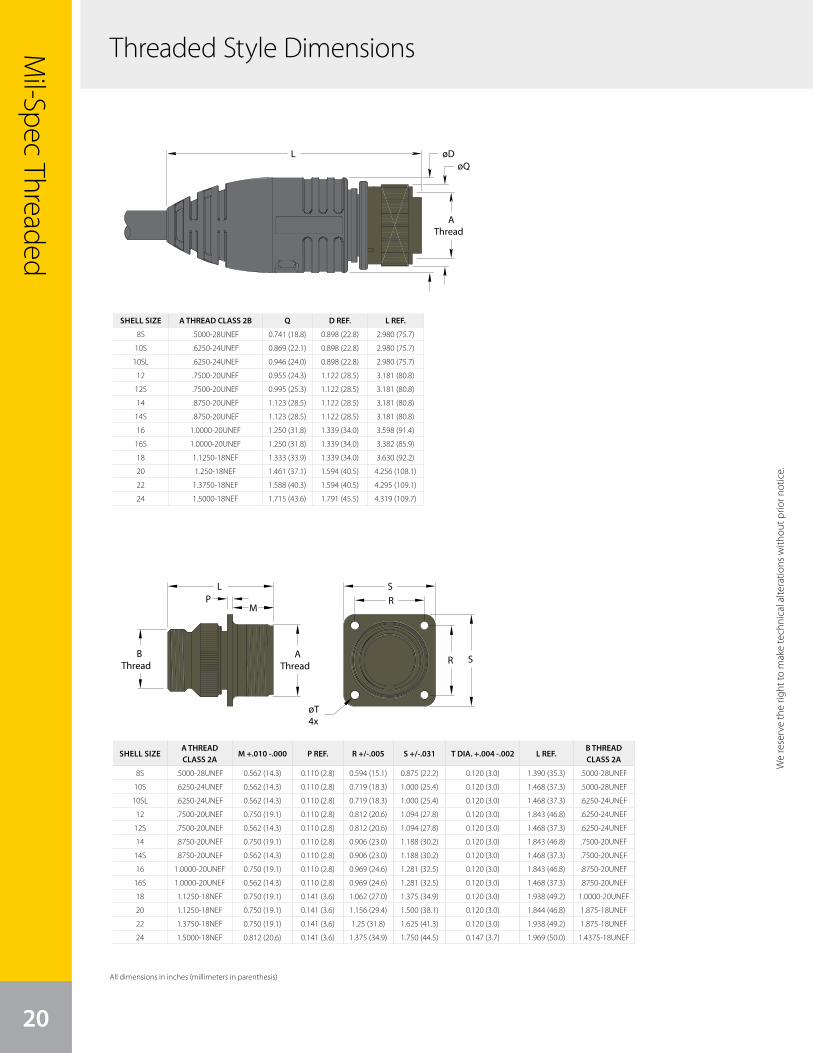
20
Mil-Spec Threaded
SHELL SIZE A THREAD CLASS 2B Q D REF. L REF.
8S .5000-28UNEF 0.741 (18.8) 0.898 (22.8) 2.980 (75.7)
10S .6250-24UNEF 0.869 (22.1) 0.898 (22.8) 2.980 (75.7)
10SL .6250-24UNEF 0.946 (24.0) 0.898 (22.8) 2.980 (75.7)
12 .7500-20UNEF 0.955 (24.3) 1.122 (28.5) 3.181 (80.8)
12S .7500-20UNEF 0.995 (25.3) 1.122 (28.5) 3.181 (80.8)
14 .8750-20UNEF 1.123 (28.5) 1.122 (28.5) 3.181 (80.8)
14S .8750-20UNEF 1.123 (28.5) 1.122 (28.5) 3.181 (80.8)
16 1.0000-20UNEF 1.250 (31.8) 1.339 (34.0) 3.598 (91.4)
16S 1.0000-20UNEF 1.250 (31.8) 1.339 (34.0) 3.382 (85.9)
18 1.1250-18NEF 1.333 (33.9) 1.339 (34.0) 3.630 (92.2)
20 1.250-18NEF 1.461 (37.1) 1.594 (40.5) 4.256 (108.1)
22 1.3750-18NEF 1.588 (40.3) 1.594 (40.5) 4.295 (109.1)
24 1.5000-18NEF 1.715 (43.6) 1.791 (45.5) 4.319 (109.7)
SHELL SIZEA THREAD CLASS 2A
M +.010 -.000 P REF. R +/-.005 S +/-.031 T DIA. +.004 -.002 L REF.B THREAD CLASS 2A
8S .5000-28UNEF 0.562 (14.3) 0.110 (2.8) 0.594 (15.1) 0.875 (22.2) 0.120 (3.0) 1.390 (35.3) .5000-28UNEF
10S .6250-24UNEF 0.562 (14.3) 0.110 (2.8) 0.719 (18.3) 1.000 (25.4) 0.120 (3.0) 1.468 (37.3) .5000-28UNEF
10SL .6250-24UNEF 0.562 (14.3) 0.110 (2.8) 0.719 (18.3) 1.000 (25.4) 0.120 (3.0) 1.468 (37.3) .6250-24UNEF
12 .7500-20UNEF 0.750 (19.1) 0.110 (2.8) 0.812 (20.6) 1.094 (27.8) 0.120 (3.0) 1.843 (46.8) .6250-24UNEF
12S .7500-20UNEF 0.562 (14.3) 0.110 (2.8) 0.812 (20.6) 1.094 (27.8) 0.120 (3.0) 1.468 (37.3) .6250-24UNEF
14 .8750-20UNEF 0.750 (19.1) 0.110 (2.8) 0.906 (23.0) 1.188 (30.2) 0.120 (3.0) 1.843 (46.8) .7500-20UNEF
14S .8750-20UNEF 0.562 (14.3) 0.110 (2.8) 0.906 (23.0) 1.188 (30.2) 0.120 (3.0) 1.468 (37.3) .7500-20UNEF
16 1.0000-20UNEF 0.750 (19.1) 0.110 (2.8) 0.969 (24.6) 1.281 (32.5) 0.120 (3.0) 1.843 (46.8) .8750-20UNEF
16S 1.0000-20UNEF 0.562 (14.3) 0.110 (2.8) 0.969 (24.6) 1.281 (32.5) 0.120 (3.0) 1.468 (37.3) .8750-20UNEF
18 1.1250-18NEF 0.750 (19.1) 0.141 (3.6) 1.062 (27.0) 1.375 (34.9) 0.120 (3.0) 1.938 (49.2) 1.0000-20UNEF
20 1.1250-18NEF 0.750 (19.1) 0.141 (3.6) 1.156 (29.4) 1.500 (38.1) 0.120 (3.0) 1.844 (46.8) 1.875-18UNEF
22 1.3750-18NEF 0.750 (19.1) 0.141 (3.6) 1.25 (31.8) 1.625 (41.3) 0.120 (3.0) 1.938 (49.2) 1.875-18UNEF
24 1.5000-18NEF 0.812 (20.6) 0.141 (3.6) 1.375 (34.9) 1.750 (44.5) 0.147 (3.7) 1.969 (50.0) 1.4375-18UNEF
We
rese
rve
the
right
to m
ake
tech
nica
l alte
ratio
ns w
ithou
t prio
r not
ice.
AThread
LP
BThread
S
R
øT4x
R
S
M
øDøQ
L
A Thread
Threaded Style Dimensions
We reserve the right to m
ake technical alterations without prior notice.
All dimensions in inches (millimeters in parenthesis)
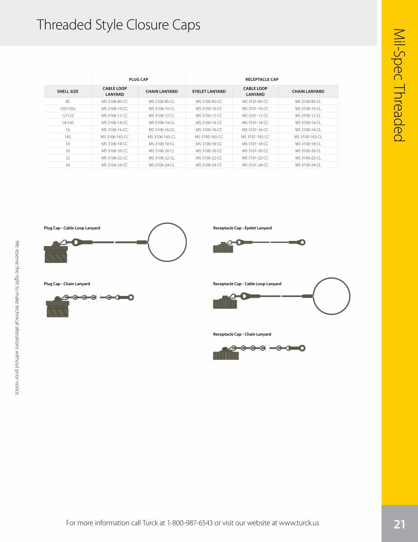
We
rese
rve
the
right
to m
ake
tech
nica
l alte
ratio
ns w
ithou
t prio
r not
ice.
Mil-Spec Threaded
21For more information call Turck at 1-800-987-6543 or visit our website at www.turck.us
PLUG CAP RECEPTACLE CAP
SHELL SIZECABLE LOOP
LANYARDCHAIN LANYARD EYELET LANYARD
CABLE LOOP LANYARD
CHAIN LANYARD
8S MS 3106-8S-CC MS 3106-8S-CL MS 3100-8S-CC MS 3101-8S-CC MS 3100-8S-CL
10S/10SL MS 3106-10-CC MS 3106-10-CL MS 3100-10-CC MS 3101-10-CC MS 3100-10-CL
12/12S MS 3106-12-CC MS 3106-12-CL MS 3100-12-CC MS 3101-12-CC MS 3100-12-CL
14/14S MS 3106-14-CC MS 3106-14-CL MS 3100-14-CC MS 3101-14-CC MS 3100-14-CL
16 MS 3106-16-CC MS 3106-16-CL MS 3100-16-CC MS 3101-16-CC MS 3100-16-CL
16S MS 3106-16S-CC MS 3106-16S-CL MS 3100-16S-CC MS 3101-16S-CC MS 3100-16S-CL
18 MS 3106-18-CC MS 3106-18-CL MS 3100-18-CC MS 3101-18-CC MS 3100-18-CL
20 MS 3106-20-CC MS 3106-20-CL MS 3100-20-CC MS 3101-20-CC MS 3100-20-CL
22 MS 3106-22-CC MS 3106-22-CL MS 3100-22-CC MS 3101-22-CC MS 3100-22-CL
24 MS 3106-24-CC MS 3106-24-CL MS 3100-24-CC MS 3101-24-CC MS 3100-24-CL
We reserve the right to m
ake technical alterations without prior notice.
Plug Cap - Cable Loop Lanyard Receptacle Cap - Eyelet Lanyard
Receptacle Cap - Cable Loop Lanyard
Receptacle Cap - Chain Lanyard
Plug Cap - Chain Lanyard
Threaded Style Closure Caps

BayonetTurck’s overmolded MIL-DTL- 26482 Series I bayonet style connectors provide a quick-connect and disconnect
solution that is well-equipped to handle applications with vibration and a high number of circuits. Overmolded
Mil-Spec connectors provide a reduction in labor over traditional field-assembled connectors and diminish the
risk of mis-wiring by providing a fully overmolded cordset assembly, allowing you to decrease downtime and save
money. Turck’s overmold design technology provides the flexibility to seal the connectors to a wide variety of
different cable types. An industry standard for connecting to instrumentation on mobile equipment, including
off-road vehicles, heavy-duty construction vehicles and data vans, the bayonet style connector is an ideal solution
for harsh applications, applications where mating and unmating are frequent, and where higher pin counts are
needed for a high number of circuits or signals.
Applications:
• Off-road vehicles
• Heavy duty construction vehicles
• Ships
• Engines
• Power Generators
• Telecommunication applications
• Industrial machinery
• Instrumentation applications such as temperature, pressure, and flow monitoring
22

Variety of cable options available
Quick connect/disconnect
“Clicks” into place
Meets NEMA 1, 3, 4, 6P
and IEC IP67, IP68 rated
Eyelet for closure cap lanyard
Shell sizes 8-24
Higher pin counts for applications with a high
number of circuits or signals
23
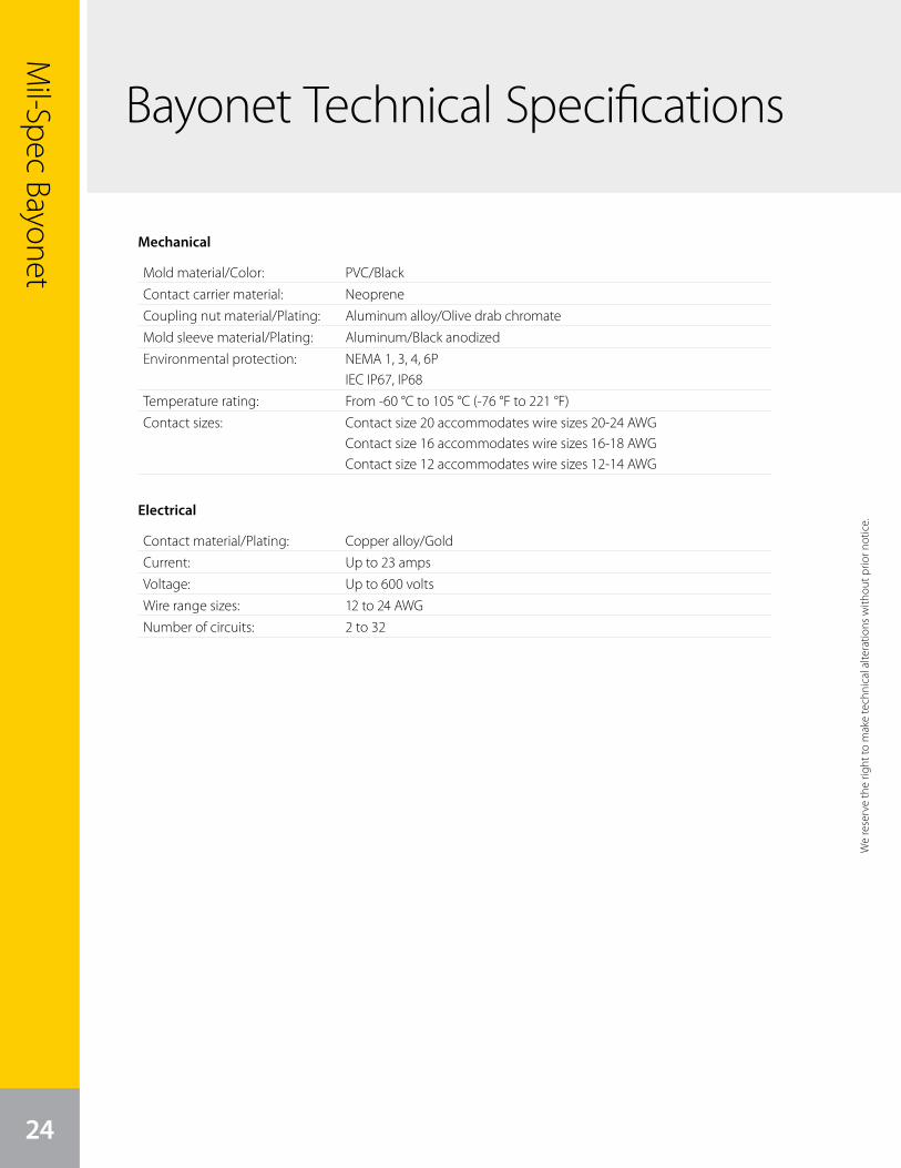
Mil-Spec Bayonet
24
Bayonet Technical Specifications
Electrical
Mold material/Color: PVC/BlackContact carrier material: NeopreneCoupling nut material/Plating: Aluminum alloy/Olive drab chromateMold sleeve material/Plating: Aluminum/Black anodizedEnvironmental protection: NEMA 1, 3, 4, 6P
IEC IP67, IP68Temperature rating: From -60 °C to 105 °C (-76 °F to 221 °F)Contact sizes: Contact size 20 accommodates wire sizes 20-24 AWG
Contact size 16 accommodates wire sizes 16-18 AWGContact size 12 accommodates wire sizes 12-14 AWG
Contact material/Plating: Copper alloy/GoldCurrent: Up to 23 ampsVoltage: Up to 600 voltsWire range sizes: 12 to 24 AWGNumber of circuits: 2 to 32
Mechanical
We
rese
rve
the
right
to m
ake
tech
nica
l alte
ratio
ns w
ithou
t prio
r not
ice.
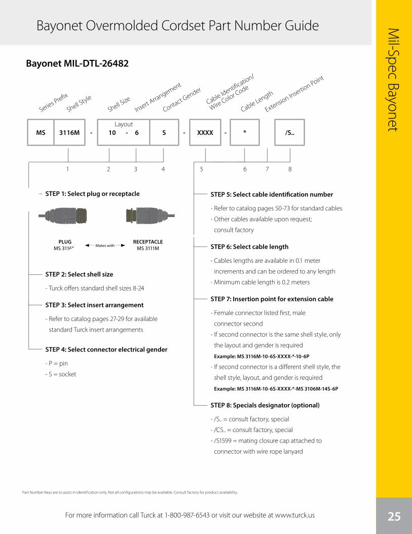
We
rese
rve
the
right
to m
ake
tech
nica
l alte
ratio
ns w
ithou
t prio
r not
ice.
Mil-Spec Bayonet
25For more information call Turck at 1-800-987-6543 or visit our website at www.turck.us
Bayonet Overmolded Cordset Part Number Guide
STEP 1: Select plug or receptacle
Series Prefix
1 2 3 4 5 6 7 8
Shell Style
Shell Size
Insert Arrangement
Contact Gender
Cable Length
Extension Insertion Point
MS 3116M - 10 - 6 S - XXXX - * /S..
Bayonet MIL-DTL-26482
Layout
STEP 2: Select shell size
- Turck offers standard shell sizes 8-24
STEP 3: Select insert arrangement
- Refer to catalog pages 27-29 for available
standard Turck insert arrangements
STEP 4: Select connector electrical gender
- P = pin
- S = socket
STEP 5: Select cable identification number
- Refer to catalog pages 50-73 for standard cables
- Other cables available upon request;
consult factory
STEP 6: Select cable length
- Cables lengths are available in 0.1 meter
increments and can be ordered to any length
- Minimum cable length is 0.2 meters
STEP 7: Insertion point for extension cable
- Female connector listed first, male
connector second
- If second connector is the same shell style, only
the layout and gender is required
Example: MS 3116M-10-6S-XXXX-*-10-6P
- If second connector is a different shell style, the
shell style, layout, and gender is required
Example: MS 3116M-10-6S-XXXX-*-MS 3106M-14S-6P
STEP 8: Specials designator (optional)
- /S.. = consult factory, special
- /CS.. = consult factory, special
- /S1599 = mating closure cap attached to
connector with wire rope lanyard
Cable Identification/
Wire Color Code
Part Number Keys are to assist in identification only. Not all configurations may be available. Consult factory for product availability.
PLUGMS 3116M Mates with
RECEPTACLEMS 3111M
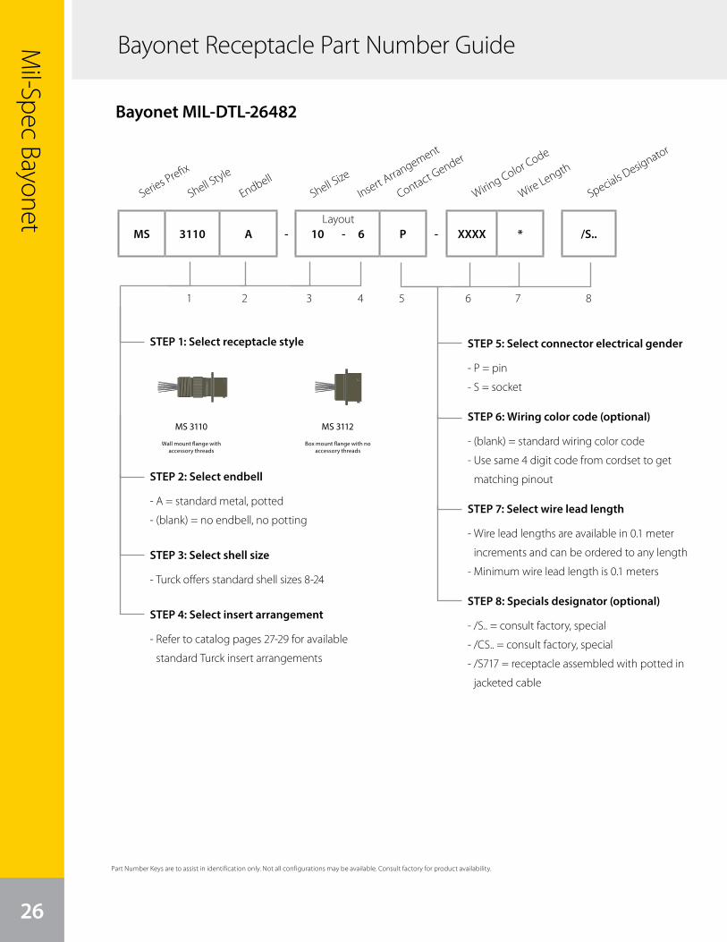
Mil-Spec Bayonet
26
Part Number Keys are to assist in identification only. Not all configurations may be available. Consult factory for product availability.
Bayonet Receptacle Part Number Guide
STEP 1: Select receptacle style
1 2 3
Bayonet MIL-DTL-26482
STEP 2: Select endbell
- A = standard metal, potted
- (blank) = no endbell, no potting
STEP 3: Select shell size
- Turck offers standard shell sizes 8-24
STEP 4: Select insert arrangement
- Refer to catalog pages 27-29 for available
standard Turck insert arrangements
STEP 5: Select connector electrical gender
- P = pin
- S = socket
STEP 6: Wiring color code (optional)
- (blank) = standard wiring color code
- Use same 4 digit code from cordset to get
matching pinout
STEP 7: Select wire lead length
- Wire lead lengths are available in 0.1 meter
increments and can be ordered to any length
- Minimum wire lead length is 0.1 meters
STEP 8: Specials designator (optional)
- /S.. = consult factory, special
- /CS.. = consult factory, special
- /S717 = receptacle assembled with potted in
jacketed cable
Series Prefix
64 5 7 8
Shell Style
EndbellShell Size
Insert Arrangement
Contact Gender
Wire Length
Wiring Color Code
Specials Designator
MS 3110 A - 10 - 6 P - XXXX * /S..Layout
MS 3110 MS 3112
We reserve the right to m
ake technical alterations without prior notice.
Wall mount flange with accessory threads
Box mount flange with no accessory threads
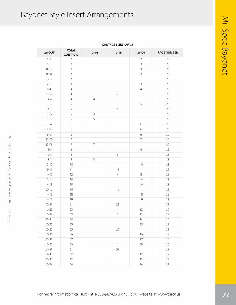
Specials Designator
Mil-Spec Bayonet
27For more information call Turck at 1-800-987-6543 or visit our website at www.turck.us
8-2 2 2 28
8-3 3 3 28
8-33 3 3 28
8-98 3 3 28
12-3 3 3 28
14-91 3 3 28
8-4 4 4 28
12-4 4 4 28
14-4 4 4 28
10-5 5 5 28
14-5 5 5 28
14-22 5 4 1 28
18-5 5 5 28
10-6 6 6 28
10-98 6 6 28
18-91 6 6 29
20-90 7 7 29
22-96 7 7 29
12-8 8 8 28
16-8 8 8 28
18-8 8 8 28
12-10 10 10 28
18-11 11 11 28
14-12 12 4 8 28
12-14 14 14 28
14-15 15 1 14 28
20-16 16 16 29
14-18 18 18 28
14-19 19 19 28
22-21 21 21 29
16-23 23 1 22 28
16-99 23 2 21 28
20-24 24 24 29
20-25 25 25 29
22-25 25 25 29
16-26 26 26 28
20-27 27 27 29
18-30 30 1 29 28
24-31 31 31 29
18-32 32 32 29
22-32 32 32 29
22-34 34 34 29
CONTACT SIZES (AWG)
LAYOUTTOTAL
CONTACTS12-14 16-18 20-24 PAGE NUMBER
We reserve the right to m
ake technical alterations without prior notice.
Bayonet Style Insert Arrangements
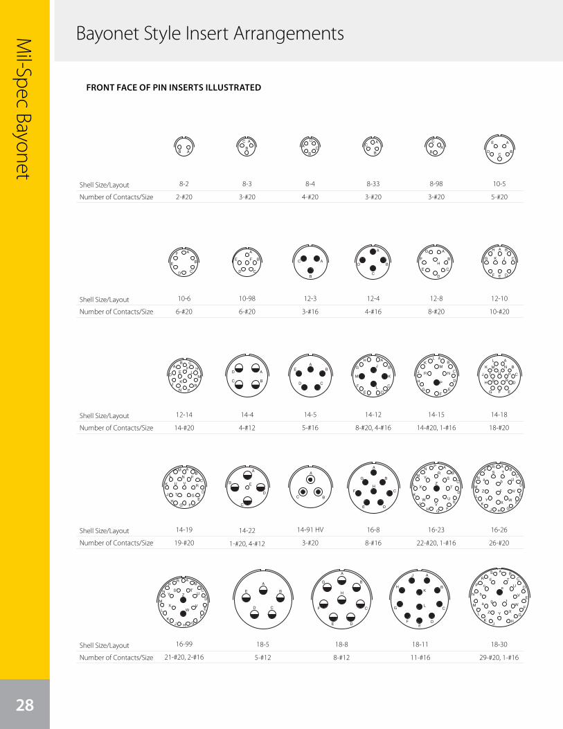
28
Mil-Spec Bayonet
Bayonet Style Insert Arrangements
Shell Size/Layout
Number of Contacts/Size
Shell Size/Layout
Number of Contacts/Size
Shell Size/Layout
Number of Contacts/Size
Shell Size/Layout
Number of Contacts/Size
Shell Size/Layout
Number of Contacts/Size
8
AB
A
B
CA
B
C
D AC
BA
C
B
A
DC
B
EAF
E
D C
B
A
FE
D C
B AC
B
A
D
C
B
A
H
G
F
E
D
C
B
A
K J
H
G
F E D
C
BA
PN
ML
KJ
HFE
D
CB
R
A
D
C
B
H
G
F
E
M
L
K
J
A
H
GF
E
D
C
BM
LK
J R
P
N
A
D
C
B
H
G F E
M
L
K
J P
N
UT
S R
A
D
C
B
HG F
E
M
L
K
J T S
R
PN
U V
Amphenol Miniature Cylindricalinsert arrangements
®
front face of pin inserts illustrated
Insert Arrangement 6-1 8-2 8-3 8-4 8-33 8-98 10-2
Service Rating I I I I I I I
Number of Contacts 1 2 3 4 3 3 2
Contact Size 20 20 20 20 20 20 16
Insert Arrangement 10-5 10-6 10-70 10-98 12-3 12-4 12-8
Service Rating I I Coax I II I I
Number of Contacts 5 6 1 6 3 4 8
Contact Size 20 20 8 Coax 20 16 16 20
Insert Arrangement 12-10 12-14 12-98 14-2 14-4 14-5 14-8
Service Rating I I I II I II I
Number of Contacts 10 14 10 2 4 5 6 2
Contact Size 20 20 20 12 12 16 20 12
Insert Arrangement 14-12 14-15 14-18 14-19 14-22 14-71 14-91HV
Service Rating I I I I I I
Number of Contacts 8 4 14 1 18 19 1 4 3 1 3
Contact Size 20 16 20 16 20 20 20 12 16 8 Coax 20
For contact legend see page 61.
A
D
C
B E
D A
C
BA
C B
AD
BC
Flashover5,000 VAC (RMS)
B A
A BC
DE
F
GH
JK
A
BH
C
D
E
F
G
AE
D C
B
8-2
2-#20
8
AB
A
B
CA
B
C
D AC
BA
C
B
A
DC
B
EAF
E
D C
B
A
FE
D C
B AC
B
A
D
C
B
A
H
G
F
E
D
C
B
A
K J
H
G
F E D
C
BA
PN
ML
KJ
HFE
D
CB
R
A
D
C
B
H
G
F
E
M
L
K
J
A
H
GF
E
D
C
BM
LK
J R
P
N
A
D
C
B
H
G F E
M
L
K
J P
N
UT
S R
A
D
C
B
HG F
E
M
L
K
J T S
R
PN
U V
Amphenol Miniature Cylindricalinsert arrangements
®
front face of pin inserts illustrated
Insert Arrangement 6-1 8-2 8-3 8-4 8-33 8-98 10-2
Service Rating I I I I I I I
Number of Contacts 1 2 3 4 3 3 2
Contact Size 20 20 20 20 20 20 16
Insert Arrangement 10-5 10-6 10-70 10-98 12-3 12-4 12-8
Service Rating I I Coax I II I I
Number of Contacts 5 6 1 6 3 4 8
Contact Size 20 20 8 Coax 20 16 16 20
Insert Arrangement 12-10 12-14 12-98 14-2 14-4 14-5 14-8
Service Rating I I I II I II I
Number of Contacts 10 14 10 2 4 5 6 2
Contact Size 20 20 20 12 12 16 20 12
Insert Arrangement 14-12 14-15 14-18 14-19 14-22 14-71 14-91HV
Service Rating I I I I I I
Number of Contacts 8 4 14 1 18 19 1 4 3 1 3
Contact Size 20 16 20 16 20 20 20 12 16 8 Coax 20
For contact legend see page 61.
A
D
C
B E
D A
C
BA
C B
AD
BC
Flashover5,000 VAC (RMS)
B A
A BC
DE
F
GH
JK
A
BH
C
D
E
F
G
AE
D C
B
10-6
6-#20
8
AB
A
B
CA
B
C
D AC
BA
C
B
A
DC
B
EAF
E
D C
B
A
FE
D C
B AC
B
A
D
C
B
A
H
G
F
E
D
C
B
A
K J
H
G
F E D
C
BA
PN
ML
KJ
HFE
D
CB
R
A
D
C
B
H
G
F
E
M
L
K
J
A
H
GF
E
D
C
BM
LK
J R
P
N
A
D
C
B
H
G F E
M
L
K
J P
N
UT
S R
A
D
C
B
HG F
E
M
L
K
J T S
R
PN
U V
Amphenol Miniature Cylindricalinsert arrangements
®
front face of pin inserts illustrated
Insert Arrangement 6-1 8-2 8-3 8-4 8-33 8-98 10-2
Service Rating I I I I I I I
Number of Contacts 1 2 3 4 3 3 2
Contact Size 20 20 20 20 20 20 16
Insert Arrangement 10-5 10-6 10-70 10-98 12-3 12-4 12-8
Service Rating I I Coax I II I I
Number of Contacts 5 6 1 6 3 4 8
Contact Size 20 20 8 Coax 20 16 16 20
Insert Arrangement 12-10 12-14 12-98 14-2 14-4 14-5 14-8
Service Rating I I I II I II I
Number of Contacts 10 14 10 2 4 5 6 2
Contact Size 20 20 20 12 12 16 20 12
Insert Arrangement 14-12 14-15 14-18 14-19 14-22 14-71 14-91HV
Service Rating I I I I I I
Number of Contacts 8 4 14 1 18 19 1 4 3 1 3
Contact Size 20 16 20 16 20 20 20 12 16 8 Coax 20
For contact legend see page 61.
A
D
C
B E
D A
C
BA
C B
AD
BC
Flashover5,000 VAC (RMS)
B A
A BC
DE
F
GH
JK
A
BH
C
D
E
F
G
AE
D C
B
12-14
14-#20
8
AB
A
B
CA
B
C
D AC
BA
C
B
A
DC
B
EAF
E
D C
B
A
FE
D C
B AC
B
A
D
C
B
A
H
G
F
E
D
C
B
A
K J
H
G
F E D
C
BA
PN
ML
KJ
HFE
D
CB
R
A
D
C
B
H
G
F
E
M
L
K
J
A
H
GF
E
D
C
BM
LK
J R
P
N
A
D
C
B
H
G F E
M
L
K
J P
N
UT
S R
A
D
C
B
HG F
E
M
L
K
J T S
R
PN
U V
Amphenol Miniature Cylindricalinsert arrangements
®
front face of pin inserts illustrated
Insert Arrangement 6-1 8-2 8-3 8-4 8-33 8-98 10-2
Service Rating I I I I I I I
Number of Contacts 1 2 3 4 3 3 2
Contact Size 20 20 20 20 20 20 16
Insert Arrangement 10-5 10-6 10-70 10-98 12-3 12-4 12-8
Service Rating I I Coax I II I I
Number of Contacts 5 6 1 6 3 4 8
Contact Size 20 20 8 Coax 20 16 16 20
Insert Arrangement 12-10 12-14 12-98 14-2 14-4 14-5 14-8
Service Rating I I I II I II I
Number of Contacts 10 14 10 2 4 5 6 2
Contact Size 20 20 20 12 12 16 20 12
Insert Arrangement 14-12 14-15 14-18 14-19 14-22 14-71 14-91HV
Service Rating I I I I I I
Number of Contacts 8 4 14 1 18 19 1 4 3 1 3
Contact Size 20 16 20 16 20 20 20 12 16 8 Coax 20
For contact legend see page 61.
A
D
C
B E
D A
C
BA
C B
AD
BC
Flashover5,000 VAC (RMS)
B A
A BC
DE
F
GH
JK
A
BH
C
D
E
F
G
AE
D C
B
14-19
19-#20
9
Insert Arrangement 18-75 18-76 18-80 18-91 HV
Service Rating Coax II I, Coax
Number of Contacts 4 3 1 6 2 6
Contact Size 8 Coax 12 Coax 8 Coax 20 8 Coax 20
A
D
C
B
H
G
F
E
A
H GF
E
D
C
B
PN
M
L
K
J
Z
Y
X
WV
U
T
SR
A
Z
YX
W
V
U
TSR
P
N
M
L
K
J HG
F
E
D
C
B
a b
c
A
M
LK
J
H
G
F
E
D
C
B
PN
A
M
L
KJ H G
F
E
D
C
B
TS
RP
NZY
XW
V
U
A
E
D C
B
A
H
G
F
E D
C
B
A
L
K
J
H
G
FE
D
C
B
A
Z Y X
W
V
U
T
S
R
P
N
M
L
KJ
H
G
F
E
D
CB
a
b
c
d
e
fg
A
Z
Y
X
W
VU
TSR
P
N
M
L
KJ H
G
F
E
D
C
B
a
b
c
d
e
f
g
h
j
AH
G
FE
D
C
B
J
A
D
C
B
A
G
F
E
D
C
BH
Amphenol Miniature Cylindricalinsert arrangements
®
front face of pin inserts illustrated
Insert Arrangement 14-AA 16-8 16-23 16-26 16-70
Service Rating I II I I N/A
Number of Contacts 4 8 22 1 26 14 1
Contact Size 12 16 20 16 20 20 12 Coax
Insert Arrangement 16-76 16-99 18-5 18-8 18-11
Service Rating I II I II
Number of Contacts 8 1 5 21 2 5 8 11
Contact Size 20 12* 2 Coax* 20 16 12 12 16
Insert Arrangement 18-30 18-32 18-71 18-72
Service Rating I I II, Coax N/A
Number of Contacts 29 1 32 8 1 10 4
Contact Size 20 16 20 16 8 Coax 20 12 Coax
Flashover1.500 VAC (RMS)
*Contact Positions Optional
AH
B
J
K
DL
R
E
M
F
N
GP
C
A
B
C
MP
L
ND
E
H
F
G
J
K
AD
C B
A
D
C
B
Flashover5,000 VAC (RMS)
A
F
E
D C
B
16-99
21-#20, 2-#16
8
AB
A
B
CA
B
C
D AC
BA
C
B
A
DC
B
EAF
E
D C
B
A
FE
D C
B AC
B
A
D
C
B
A
H
G
F
E
D
C
B
A
K J
H
G
F E D
C
BA
PN
ML
KJ
HFE
D
CB
R
A
D
C
B
H
G
F
E
M
L
K
J
A
H
GF
E
D
C
BM
LK
J R
P
N
A
D
C
B
H
G F E
M
L
K
J P
N
UT
S R
A
D
C
B
HG F
E
M
L
K
J T S
R
PN
U V
Amphenol Miniature Cylindricalinsert arrangements
®
front face of pin inserts illustrated
Insert Arrangement 6-1 8-2 8-3 8-4 8-33 8-98 10-2
Service Rating I I I I I I I
Number of Contacts 1 2 3 4 3 3 2
Contact Size 20 20 20 20 20 20 16
Insert Arrangement 10-5 10-6 10-70 10-98 12-3 12-4 12-8
Service Rating I I Coax I II I I
Number of Contacts 5 6 1 6 3 4 8
Contact Size 20 20 8 Coax 20 16 16 20
Insert Arrangement 12-10 12-14 12-98 14-2 14-4 14-5 14-8
Service Rating I I I II I II I
Number of Contacts 10 14 10 2 4 5 6 2
Contact Size 20 20 20 12 12 16 20 12
Insert Arrangement 14-12 14-15 14-18 14-19 14-22 14-71 14-91HV
Service Rating I I I I I I
Number of Contacts 8 4 14 1 18 19 1 4 3 1 3
Contact Size 20 16 20 16 20 20 20 12 16 8 Coax 20
For contact legend see page 61.
A
D
C
B E
D A
C
BA
C B
AD
BC
Flashover5,000 VAC (RMS)
B A
A BC
DE
F
GH
JK
A
BH
C
D
E
F
G
AE
D C
B
8-3
3-#20
8
AB
A
B
CA
B
C
D AC
BA
C
B
A
DC
B
EAF
E
D C
B
A
FE
D C
B AC
B
A
D
C
B
A
H
G
F
E
D
C
B
A
K J
H
G
F E D
C
BA
PN
ML
KJ
HFE
D
CB
R
A
D
C
B
H
G
F
E
M
L
K
J
A
H
GF
E
D
C
BM
LK
J R
P
N
A
D
C
B
H
G F E
M
L
K
J P
N
UT
S R
A
D
C
B
HG F
E
M
L
K
J T S
R
PN
U V
Amphenol Miniature Cylindricalinsert arrangements
®
front face of pin inserts illustrated
Insert Arrangement 6-1 8-2 8-3 8-4 8-33 8-98 10-2
Service Rating I I I I I I I
Number of Contacts 1 2 3 4 3 3 2
Contact Size 20 20 20 20 20 20 16
Insert Arrangement 10-5 10-6 10-70 10-98 12-3 12-4 12-8
Service Rating I I Coax I II I I
Number of Contacts 5 6 1 6 3 4 8
Contact Size 20 20 8 Coax 20 16 16 20
Insert Arrangement 12-10 12-14 12-98 14-2 14-4 14-5 14-8
Service Rating I I I II I II I
Number of Contacts 10 14 10 2 4 5 6 2
Contact Size 20 20 20 12 12 16 20 12
Insert Arrangement 14-12 14-15 14-18 14-19 14-22 14-71 14-91HV
Service Rating I I I I I I
Number of Contacts 8 4 14 1 18 19 1 4 3 1 3
Contact Size 20 16 20 16 20 20 20 12 16 8 Coax 20
For contact legend see page 61.
A
D
C
B E
D A
C
BA
C B
AD
BC
Flashover5,000 VAC (RMS)
B A
A BC
DE
F
GH
JK
A
BH
C
D
E
F
G
AE
D C
B
10-98
6-#20
8
AB
A
B
CA
B
C
D AC
BA
C
B
A
DC
B
EAF
E
D C
B
A
FE
D C
B AC
B
A
D
C
B
A
H
G
F
E
D
C
B
A
K J
H
G
F E D
C
BA
PN
ML
KJ
HFE
D
CB
R
A
D
C
B
H
G
F
E
M
L
K
J
A
H
GF
E
D
C
BM
LK
J R
P
N
A
D
C
B
H
G F E
M
L
K
J P
N
UT
S R
A
D
C
B
HG F
E
M
L
K
J T S
R
PN
U V
Amphenol Miniature Cylindricalinsert arrangements
®
front face of pin inserts illustrated
Insert Arrangement 6-1 8-2 8-3 8-4 8-33 8-98 10-2
Service Rating I I I I I I I
Number of Contacts 1 2 3 4 3 3 2
Contact Size 20 20 20 20 20 20 16
Insert Arrangement 10-5 10-6 10-70 10-98 12-3 12-4 12-8
Service Rating I I Coax I II I I
Number of Contacts 5 6 1 6 3 4 8
Contact Size 20 20 8 Coax 20 16 16 20
Insert Arrangement 12-10 12-14 12-98 14-2 14-4 14-5 14-8
Service Rating I I I II I II I
Number of Contacts 10 14 10 2 4 5 6 2
Contact Size 20 20 20 12 12 16 20 12
Insert Arrangement 14-12 14-15 14-18 14-19 14-22 14-71 14-91HV
Service Rating I I I I I I
Number of Contacts 8 4 14 1 18 19 1 4 3 1 3
Contact Size 20 16 20 16 20 20 20 12 16 8 Coax 20
For contact legend see page 61.
A
D
C
B E
D A
C
BA
C B
AD
BC
Flashover5,000 VAC (RMS)
B A
A BC
DE
F
GH
JK
A
BH
C
D
E
F
G
AE
D C
B
14-4
4-#12
8
AB
A
B
CA
B
C
D AC
BA
C
B
A
DC
B
EAF
E
D C
B
A
FE
D C
B AC
B
A
D
C
B
A
H
G
F
E
D
C
B
A
K J
H
G
F E D
C
BA
PN
ML
KJ
HFE
D
CB
R
A
D
C
B
H
G
F
E
M
L
K
J
A
H
GF
E
D
C
BM
LK
J R
P
N
A
D
C
B
H
G F E
M
L
K
J P
N
UT
S R
A
D
C
B
HG F
E
M
L
K
J T S
R
PN
U V
Amphenol Miniature Cylindricalinsert arrangements
®
front face of pin inserts illustrated
Insert Arrangement 6-1 8-2 8-3 8-4 8-33 8-98 10-2
Service Rating I I I I I I I
Number of Contacts 1 2 3 4 3 3 2
Contact Size 20 20 20 20 20 20 16
Insert Arrangement 10-5 10-6 10-70 10-98 12-3 12-4 12-8
Service Rating I I Coax I II I I
Number of Contacts 5 6 1 6 3 4 8
Contact Size 20 20 8 Coax 20 16 16 20
Insert Arrangement 12-10 12-14 12-98 14-2 14-4 14-5 14-8
Service Rating I I I II I II I
Number of Contacts 10 14 10 2 4 5 6 2
Contact Size 20 20 20 12 12 16 20 12
Insert Arrangement 14-12 14-15 14-18 14-19 14-22 14-71 14-91HV
Service Rating I I I I I I
Number of Contacts 8 4 14 1 18 19 1 4 3 1 3
Contact Size 20 16 20 16 20 20 20 12 16 8 Coax 20
For contact legend see page 61.
A
D
C
B E
D A
C
BA
C B
AD
BC
Flashover5,000 VAC (RMS)
B A
A BC
DE
F
GH
JK
A
BH
C
D
E
F
G
AE
D C
B
14-22
1-#20, 4-#12
9
Insert Arrangement 18-75 18-76 18-80 18-91 HV
Service Rating Coax II I, Coax
Number of Contacts 4 3 1 6 2 6
Contact Size 8 Coax 12 Coax 8 Coax 20 8 Coax 20
A
D
C
B
H
G
F
E
A
H GF
E
D
C
B
PN
M
L
K
J
Z
Y
X
WV
U
T
SR
A
Z
YX
W
V
U
TSR
P
N
M
L
K
J HG
F
E
D
C
B
a b
c
A
M
LK
J
H
G
F
E
D
C
B
PN
A
M
L
KJ H G
F
E
D
C
B
TS
RP
NZY
XW
V
U
A
E
D C
B
A
H
G
F
E D
C
B
A
L
K
J
H
G
FE
D
C
B
A
Z Y X
W
V
U
T
S
R
P
N
M
L
KJ
H
G
F
E
D
CB
a
b
c
d
e
fg
A
Z
Y
X
W
VU
TSR
P
N
M
L
KJ H
G
F
E
D
C
B
a
b
c
d
e
f
g
h
j
AH
G
FE
D
C
B
J
A
D
C
B
A
G
F
E
D
C
BH
Amphenol Miniature Cylindricalinsert arrangements
®
front face of pin inserts illustrated
Insert Arrangement 14-AA 16-8 16-23 16-26 16-70
Service Rating I II I I N/A
Number of Contacts 4 8 22 1 26 14 1
Contact Size 12 16 20 16 20 20 12 Coax
Insert Arrangement 16-76 16-99 18-5 18-8 18-11
Service Rating I II I II
Number of Contacts 8 1 5 21 2 5 8 11
Contact Size 20 12* 2 Coax* 20 16 12 12 16
Insert Arrangement 18-30 18-32 18-71 18-72
Service Rating I I II, Coax N/A
Number of Contacts 29 1 32 8 1 10 4
Contact Size 20 16 20 16 8 Coax 20 12 Coax
Flashover1.500 VAC (RMS)
*Contact Positions Optional
AH
B
J
K
DL
R
E
M
F
N
GP
C
A
B
C
MP
L
ND
E
H
F
G
J
K
AD
C B
A
D
C
B
Flashover5,000 VAC (RMS)
A
F
E
D C
B
18-5
5-#12
9
Insert Arrangement 18-75 18-76 18-80 18-91 HV
Service Rating Coax II I, Coax
Number of Contacts 4 3 1 6 2 6
Contact Size 8 Coax 12 Coax 8 Coax 20 8 Coax 20
A
D
C
B
H
G
F
E
A
H GF
E
D
C
B
PN
M
L
K
J
Z
Y
X
WV
U
T
SR
A
Z
YX
W
V
U
TSR
P
N
M
L
K
J HG
F
E
D
C
B
a b
c
A
M
LK
J
H
G
F
E
D
C
B
PN
A
M
L
KJ H G
F
E
D
C
B
TS
RP
NZY
XW
V
U
A
E
D C
B
A
H
G
F
E D
C
B
A
L
K
J
H
G
FE
D
C
B
A
Z Y X
W
V
U
T
S
R
P
N
M
L
KJ
H
G
F
E
D
CB
a
b
c
d
e
fg
A
Z
Y
X
W
VU
TSR
P
N
M
L
KJ H
G
F
E
D
C
B
a
b
c
d
e
f
g
h
j
AH
G
FE
D
C
B
J
A
D
C
B
A
G
F
E
D
C
BH
Amphenol Miniature Cylindricalinsert arrangements
®
front face of pin inserts illustrated
Insert Arrangement 14-AA 16-8 16-23 16-26 16-70
Service Rating I II I I N/A
Number of Contacts 4 8 22 1 26 14 1
Contact Size 12 16 20 16 20 20 12 Coax
Insert Arrangement 16-76 16-99 18-5 18-8 18-11
Service Rating I II I II
Number of Contacts 8 1 5 21 2 5 8 11
Contact Size 20 12* 2 Coax* 20 16 12 12 16
Insert Arrangement 18-30 18-32 18-71 18-72
Service Rating I I II, Coax N/A
Number of Contacts 29 1 32 8 1 10 4
Contact Size 20 16 20 16 8 Coax 20 12 Coax
Flashover1.500 VAC (RMS)
*Contact Positions Optional
AH
B
J
K
DL
R
E
M
F
N
GP
C
A
B
C
MP
L
ND
E
H
F
G
J
K
AD
C B
A
D
C
B
Flashover5,000 VAC (RMS)
A
F
E
D C
B
18-8
8-#12
9
Insert Arrangement 18-75 18-76 18-80 18-91 HV
Service Rating Coax II I, Coax
Number of Contacts 4 3 1 6 2 6
Contact Size 8 Coax 12 Coax 8 Coax 20 8 Coax 20
A
D
C
B
H
G
F
E
A
H GF
E
D
C
B
PN
M
L
K
J
Z
Y
X
WV
U
T
SR
A
Z
YX
W
V
U
TSR
P
N
M
L
K
J HG
F
E
D
C
B
a b
c
A
M
LK
J
H
G
F
E
D
C
B
PN
A
M
L
KJ H G
F
E
D
C
B
TS
RP
NZY
XW
V
U
A
E
D C
B
A
H
G
F
E D
C
B
A
L
K
J
H
G
FE
D
C
B
A
Z Y X
W
V
U
T
S
R
P
N
M
L
KJ
H
G
F
E
D
CB
a
b
c
d
e
fg
A
Z
Y
X
W
VU
TSR
P
N
M
L
KJ H
G
F
E
D
C
B
a
b
c
d
e
f
g
h
j
AH
G
FE
D
C
B
J
A
D
C
B
A
G
F
E
D
C
BH
Amphenol Miniature Cylindricalinsert arrangements
®
front face of pin inserts illustrated
Insert Arrangement 14-AA 16-8 16-23 16-26 16-70
Service Rating I II I I N/A
Number of Contacts 4 8 22 1 26 14 1
Contact Size 12 16 20 16 20 20 12 Coax
Insert Arrangement 16-76 16-99 18-5 18-8 18-11
Service Rating I II I II
Number of Contacts 8 1 5 21 2 5 8 11
Contact Size 20 12* 2 Coax* 20 16 12 12 16
Insert Arrangement 18-30 18-32 18-71 18-72
Service Rating I I II, Coax N/A
Number of Contacts 29 1 32 8 1 10 4
Contact Size 20 16 20 16 8 Coax 20 12 Coax
Flashover1.500 VAC (RMS)
*Contact Positions Optional
AH
B
J
K
DL
R
E
M
F
N
GP
C
A
B
C
MP
L
ND
E
H
F
G
J
K
AD
C B
A
D
C
B
Flashover5,000 VAC (RMS)
A
F
E
D C
B
18-11
11-#16
9
Insert Arrangement 18-75 18-76 18-80 18-91 HV
Service Rating Coax II I, Coax
Number of Contacts 4 3 1 6 2 6
Contact Size 8 Coax 12 Coax 8 Coax 20 8 Coax 20
A
D
C
B
H
G
F
E
A
H GF
E
D
C
B
PN
M
L
K
J
Z
Y
X
WV
U
T
SR
A
Z
YX
W
V
U
TSR
P
N
M
L
K
J HG
F
E
D
C
B
a b
c
A
M
LK
J
H
G
F
E
D
C
B
PN
A
M
L
KJ H G
F
E
D
C
B
TS
RP
NZY
XW
V
U
A
E
D C
B
A
H
G
F
E D
C
B
A
L
K
J
H
G
FE
D
C
B
A
Z Y X
W
V
U
T
S
R
P
N
M
L
KJ
H
G
F
E
D
CB
a
b
c
d
e
fg
A
Z
Y
X
W
VU
TSR
P
N
M
L
KJ H
G
F
E
D
C
B
a
b
c
d
e
f
g
h
j
AH
G
FE
D
C
B
J
A
D
C
B
A
G
F
E
D
C
BH
Amphenol Miniature Cylindricalinsert arrangements
®
front face of pin inserts illustrated
Insert Arrangement 14-AA 16-8 16-23 16-26 16-70
Service Rating I II I I N/A
Number of Contacts 4 8 22 1 26 14 1
Contact Size 12 16 20 16 20 20 12 Coax
Insert Arrangement 16-76 16-99 18-5 18-8 18-11
Service Rating I II I II
Number of Contacts 8 1 5 21 2 5 8 11
Contact Size 20 12* 2 Coax* 20 16 12 12 16
Insert Arrangement 18-30 18-32 18-71 18-72
Service Rating I I II, Coax N/A
Number of Contacts 29 1 32 8 1 10 4
Contact Size 20 16 20 16 8 Coax 20 12 Coax
Flashover1.500 VAC (RMS)
*Contact Positions Optional
AH
B
J
K
DL
R
E
M
F
N
GP
C
A
B
C
MP
L
ND
E
H
F
G
J
K
AD
C B
A
D
C
B
Flashover5,000 VAC (RMS)
A
F
E
D C
B
18-30
29-#20, 1-#16
8
AB
A
B
CA
B
C
D AC
BA
C
B
A
DC
B
EAF
E
D C
B
A
FE
D C
B AC
B
A
D
C
B
A
H
G
F
E
D
C
B
A
K J
H
G
F E D
C
BA
PN
ML
KJ
HFE
D
CB
R
A
D
C
B
H
G
F
E
M
L
K
J
A
H
GF
E
D
C
BM
LK
J R
P
N
A
D
C
B
H
G F E
M
L
K
J P
N
UT
S R
A
D
C
B
HG F
E
M
L
K
J T S
R
PN
U V
Amphenol Miniature Cylindricalinsert arrangements
®
front face of pin inserts illustrated
Insert Arrangement 6-1 8-2 8-3 8-4 8-33 8-98 10-2
Service Rating I I I I I I I
Number of Contacts 1 2 3 4 3 3 2
Contact Size 20 20 20 20 20 20 16
Insert Arrangement 10-5 10-6 10-70 10-98 12-3 12-4 12-8
Service Rating I I Coax I II I I
Number of Contacts 5 6 1 6 3 4 8
Contact Size 20 20 8 Coax 20 16 16 20
Insert Arrangement 12-10 12-14 12-98 14-2 14-4 14-5 14-8
Service Rating I I I II I II I
Number of Contacts 10 14 10 2 4 5 6 2
Contact Size 20 20 20 12 12 16 20 12
Insert Arrangement 14-12 14-15 14-18 14-19 14-22 14-71 14-91HV
Service Rating I I I I I I
Number of Contacts 8 4 14 1 18 19 1 4 3 1 3
Contact Size 20 16 20 16 20 20 20 12 16 8 Coax 20
For contact legend see page 61.
A
D
C
B E
D A
C
BA
C B
AD
BC
Flashover5,000 VAC (RMS)
B A
A BC
DE
F
GH
JK
A
BH
C
D
E
F
G
AE
D C
B
8-4
4-#20
8
AB
A
B
CA
B
C
D AC
BA
C
B
A
DC
B
EAF
E
D C
B
A
FE
D C
B AC
B
A
D
C
B
A
H
G
F
E
D
C
B
A
K J
H
G
F E D
C
BA
PN
ML
KJ
HFE
D
CB
R
A
D
C
B
H
G
F
E
M
L
K
J
A
H
GF
E
D
C
BM
LK
J R
P
N
A
D
C
B
H
G F E
M
L
K
J P
N
UT
S R
A
D
C
B
HG F
E
M
L
K
J T S
R
PN
U V
Amphenol Miniature Cylindricalinsert arrangements
®
front face of pin inserts illustrated
Insert Arrangement 6-1 8-2 8-3 8-4 8-33 8-98 10-2
Service Rating I I I I I I I
Number of Contacts 1 2 3 4 3 3 2
Contact Size 20 20 20 20 20 20 16
Insert Arrangement 10-5 10-6 10-70 10-98 12-3 12-4 12-8
Service Rating I I Coax I II I I
Number of Contacts 5 6 1 6 3 4 8
Contact Size 20 20 8 Coax 20 16 16 20
Insert Arrangement 12-10 12-14 12-98 14-2 14-4 14-5 14-8
Service Rating I I I II I II I
Number of Contacts 10 14 10 2 4 5 6 2
Contact Size 20 20 20 12 12 16 20 12
Insert Arrangement 14-12 14-15 14-18 14-19 14-22 14-71 14-91HV
Service Rating I I I I I I
Number of Contacts 8 4 14 1 18 19 1 4 3 1 3
Contact Size 20 16 20 16 20 20 20 12 16 8 Coax 20
For contact legend see page 61.
A
D
C
B E
D A
C
BA
C B
AD
BC
Flashover5,000 VAC (RMS)
B A
A BC
DE
F
GH
JK
A
BH
C
D
E
F
G
AE
D C
B
12-3
3-#16
8
AB
A
B
CA
B
C
D AC
BA
C
B
A
DC
B
EAF
E
D C
B
A
FE
D C
B AC
B
A
D
C
B
A
H
G
F
E
D
C
B
A
K J
H
G
F E D
C
BA
PN
ML
KJ
HFE
D
CB
R
A
D
C
B
H
G
F
E
M
L
K
J
A
H
GF
E
D
C
BM
LK
J R
P
N
A
D
C
B
H
G F E
M
L
K
J P
N
UT
S R
A
D
C
B
HG F
E
M
L
K
J T S
R
PN
U V
Amphenol Miniature Cylindricalinsert arrangements
®
front face of pin inserts illustrated
Insert Arrangement 6-1 8-2 8-3 8-4 8-33 8-98 10-2
Service Rating I I I I I I I
Number of Contacts 1 2 3 4 3 3 2
Contact Size 20 20 20 20 20 20 16
Insert Arrangement 10-5 10-6 10-70 10-98 12-3 12-4 12-8
Service Rating I I Coax I II I I
Number of Contacts 5 6 1 6 3 4 8
Contact Size 20 20 8 Coax 20 16 16 20
Insert Arrangement 12-10 12-14 12-98 14-2 14-4 14-5 14-8
Service Rating I I I II I II I
Number of Contacts 10 14 10 2 4 5 6 2
Contact Size 20 20 20 12 12 16 20 12
Insert Arrangement 14-12 14-15 14-18 14-19 14-22 14-71 14-91HV
Service Rating I I I I I I
Number of Contacts 8 4 14 1 18 19 1 4 3 1 3
Contact Size 20 16 20 16 20 20 20 12 16 8 Coax 20
For contact legend see page 61.
A
D
C
B E
D A
C
BA
C B
AD
BC
Flashover5,000 VAC (RMS)
B A
A BC
DE
F
GH
JK
A
BH
C
D
E
F
G
AE
D C
B
14-5
5-#16
8
AB
A
B
CA
B
C
D AC
BA
C
B
A
DC
B
EAF
E
D C
B
A
FE
D C
B AC
B
A
D
C
B
A
H
G
F
E
D
C
B
A
K J
H
G
F E D
C
BA
PN
ML
KJ
HFE
D
CB
R
A
D
C
B
H
G
F
E
M
L
K
J
A
H
GF
E
D
C
BM
LK
J R
P
N
A
D
C
B
H
G F E
M
L
K
J P
N
UT
S R
A
D
C
B
HG F
E
M
L
K
J T S
R
PN
U V
Amphenol Miniature Cylindricalinsert arrangements
®
front face of pin inserts illustrated
Insert Arrangement 6-1 8-2 8-3 8-4 8-33 8-98 10-2
Service Rating I I I I I I I
Number of Contacts 1 2 3 4 3 3 2
Contact Size 20 20 20 20 20 20 16
Insert Arrangement 10-5 10-6 10-70 10-98 12-3 12-4 12-8
Service Rating I I Coax I II I I
Number of Contacts 5 6 1 6 3 4 8
Contact Size 20 20 8 Coax 20 16 16 20
Insert Arrangement 12-10 12-14 12-98 14-2 14-4 14-5 14-8
Service Rating I I I II I II I
Number of Contacts 10 14 10 2 4 5 6 2
Contact Size 20 20 20 12 12 16 20 12
Insert Arrangement 14-12 14-15 14-18 14-19 14-22 14-71 14-91HV
Service Rating I I I I I I
Number of Contacts 8 4 14 1 18 19 1 4 3 1 3
Contact Size 20 16 20 16 20 20 20 12 16 8 Coax 20
For contact legend see page 61.
A
D
C
B E
D A
C
BA
C B
AD
BC
Flashover5,000 VAC (RMS)
B A
A BC
DE
F
GH
JK
A
BH
C
D
E
F
G
AE
D C
B
14-12
8-#20, 4-#16
8
AB
A
B
CA
B
C
D AC
BA
C
B
A
DC
B
EAF
E
D C
B
A
FE
D C
B AC
B
A
D
C
B
A
H
G
F
E
D
C
B
A
K J
H
G
F E D
C
BA
PN
ML
KJ
HFE
D
CB
R
A
D
C
B
H
G
F
E
M
L
K
J
A
H
GF
E
D
C
BM
LK
J R
P
N
A
D
C
B
H
G F E
M
L
K
J P
N
UT
S R
A
D
C
B
HG F
E
M
L
K
J T S
R
PN
U V
Amphenol Miniature Cylindricalinsert arrangements
®
front face of pin inserts illustrated
Insert Arrangement 6-1 8-2 8-3 8-4 8-33 8-98 10-2
Service Rating I I I I I I I
Number of Contacts 1 2 3 4 3 3 2
Contact Size 20 20 20 20 20 20 16
Insert Arrangement 10-5 10-6 10-70 10-98 12-3 12-4 12-8
Service Rating I I Coax I II I I
Number of Contacts 5 6 1 6 3 4 8
Contact Size 20 20 8 Coax 20 16 16 20
Insert Arrangement 12-10 12-14 12-98 14-2 14-4 14-5 14-8
Service Rating I I I II I II I
Number of Contacts 10 14 10 2 4 5 6 2
Contact Size 20 20 20 12 12 16 20 12
Insert Arrangement 14-12 14-15 14-18 14-19 14-22 14-71 14-91HV
Service Rating I I I I I I
Number of Contacts 8 4 14 1 18 19 1 4 3 1 3
Contact Size 20 16 20 16 20 20 20 12 16 8 Coax 20
For contact legend see page 61.
A
D
C
B E
D A
C
BA
C B
AD
BC
Flashover5,000 VAC (RMS)
B A
A BC
DE
F
GH
JK
A
BH
C
D
E
F
G
AE
D C
B
14-15
14-#20, 1-#16
8
AB
A
B
CA
B
C
D AC
BA
C
B
A
DC
B
EAF
E
D C
B
A
FE
D C
B AC
B
A
D
C
B
A
H
G
F
E
D
C
B
A
K J
H
G
F E D
C
BA
PN
ML
KJ
HFE
D
CB
R
A
D
C
B
H
G
F
E
M
L
K
J
A
H
GF
E
D
C
BM
LK
J R
P
N
A
D
C
B
H
G F E
M
L
K
J P
N
UT
S R
A
D
C
B
HG F
E
M
L
K
J T S
R
PN
U V
Amphenol Miniature Cylindricalinsert arrangements
®
front face of pin inserts illustrated
Insert Arrangement 6-1 8-2 8-3 8-4 8-33 8-98 10-2
Service Rating I I I I I I I
Number of Contacts 1 2 3 4 3 3 2
Contact Size 20 20 20 20 20 20 16
Insert Arrangement 10-5 10-6 10-70 10-98 12-3 12-4 12-8
Service Rating I I Coax I II I I
Number of Contacts 5 6 1 6 3 4 8
Contact Size 20 20 8 Coax 20 16 16 20
Insert Arrangement 12-10 12-14 12-98 14-2 14-4 14-5 14-8
Service Rating I I I II I II I
Number of Contacts 10 14 10 2 4 5 6 2
Contact Size 20 20 20 12 12 16 20 12
Insert Arrangement 14-12 14-15 14-18 14-19 14-22 14-71 14-91HV
Service Rating I I I I I I
Number of Contacts 8 4 14 1 18 19 1 4 3 1 3
Contact Size 20 16 20 16 20 20 20 12 16 8 Coax 20
For contact legend see page 61.
A
D
C
B E
D A
C
BA
C B
AD
BC
Flashover5,000 VAC (RMS)
B A
A BC
DE
F
GH
JK
A
BH
C
D
E
F
G
AE
D C
B
14-18
18-#20
8
AB
A
B
CA
B
C
D AC
BA
C
B
A
DC
B
EAF
E
D C
B
A
FE
D C
B AC
B
A
D
C
B
A
H
G
F
E
D
C
B
A
K J
H
G
F E D
C
BA
PN
ML
KJ
HFE
D
CB
R
A
D
C
B
H
G
F
E
M
L
K
J
A
H
GF
E
D
C
BM
LK
J R
P
N
A
D
C
B
H
G F E
M
L
K
J P
N
UT
S R
A
D
C
B
HG F
E
M
L
K
J T S
R
PN
U V
Amphenol Miniature Cylindricalinsert arrangements
®
front face of pin inserts illustrated
Insert Arrangement 6-1 8-2 8-3 8-4 8-33 8-98 10-2
Service Rating I I I I I I I
Number of Contacts 1 2 3 4 3 3 2
Contact Size 20 20 20 20 20 20 16
Insert Arrangement 10-5 10-6 10-70 10-98 12-3 12-4 12-8
Service Rating I I Coax I II I I
Number of Contacts 5 6 1 6 3 4 8
Contact Size 20 20 8 Coax 20 16 16 20
Insert Arrangement 12-10 12-14 12-98 14-2 14-4 14-5 14-8
Service Rating I I I II I II I
Number of Contacts 10 14 10 2 4 5 6 2
Contact Size 20 20 20 12 12 16 20 12
Insert Arrangement 14-12 14-15 14-18 14-19 14-22 14-71 14-91HV
Service Rating I I I I I I
Number of Contacts 8 4 14 1 18 19 1 4 3 1 3
Contact Size 20 16 20 16 20 20 20 12 16 8 Coax 20
For contact legend see page 61.
A
D
C
B E
D A
C
BA
C B
AD
BC
Flashover5,000 VAC (RMS)
B A
A BC
DE
F
GH
JK
A
BH
C
D
E
F
G
AE
D C
B
14-91 HV
3-#20
8
AB
A
B
CA
B
C
D AC
BA
C
B
A
DC
B
EAF
E
D C
B
A
FE
D C
B AC
B
A
D
C
B
A
H
G
F
E
D
C
B
A
K J
H
G
F E D
C
BA
PN
ML
KJ
HFE
D
CB
R
A
D
C
B
H
G
F
E
M
L
K
J
A
H
GF
E
D
C
BM
LK
J R
P
N
A
D
C
B
H
G F E
M
L
K
J P
N
UT
S R
A
D
C
B
HG F
E
M
L
K
J T S
R
PN
U V
Amphenol Miniature Cylindricalinsert arrangements
®
front face of pin inserts illustrated
Insert Arrangement 6-1 8-2 8-3 8-4 8-33 8-98 10-2
Service Rating I I I I I I I
Number of Contacts 1 2 3 4 3 3 2
Contact Size 20 20 20 20 20 20 16
Insert Arrangement 10-5 10-6 10-70 10-98 12-3 12-4 12-8
Service Rating I I Coax I II I I
Number of Contacts 5 6 1 6 3 4 8
Contact Size 20 20 8 Coax 20 16 16 20
Insert Arrangement 12-10 12-14 12-98 14-2 14-4 14-5 14-8
Service Rating I I I II I II I
Number of Contacts 10 14 10 2 4 5 6 2
Contact Size 20 20 20 12 12 16 20 12
Insert Arrangement 14-12 14-15 14-18 14-19 14-22 14-71 14-91HV
Service Rating I I I I I I
Number of Contacts 8 4 14 1 18 19 1 4 3 1 3
Contact Size 20 16 20 16 20 20 20 12 16 8 Coax 20
For contact legend see page 61.
A
D
C
B E
D A
C
BA
C B
AD
BC
Flashover5,000 VAC (RMS)
B A
A BC
DE
F
GH
JK
A
BH
C
D
E
F
G
AE
D C
B
8-33
3-#20
8
AB
A
B
CA
B
C
D AC
BA
C
B
A
DC
B
EAF
E
D C
B
A
FE
D C
B AC
B
A
D
C
B
A
H
G
F
E
D
C
B
A
K J
H
G
F E D
C
BA
PN
ML
KJ
HFE
D
CB
R
A
D
C
B
H
G
F
E
M
L
K
J
A
H
GF
E
D
C
BM
LK
J R
P
N
A
D
C
B
H
G F E
M
L
K
J P
N
UT
S R
A
D
C
B
HG F
E
M
L
K
J T S
R
PN
U V
Amphenol Miniature Cylindricalinsert arrangements
®
front face of pin inserts illustrated
Insert Arrangement 6-1 8-2 8-3 8-4 8-33 8-98 10-2
Service Rating I I I I I I I
Number of Contacts 1 2 3 4 3 3 2
Contact Size 20 20 20 20 20 20 16
Insert Arrangement 10-5 10-6 10-70 10-98 12-3 12-4 12-8
Service Rating I I Coax I II I I
Number of Contacts 5 6 1 6 3 4 8
Contact Size 20 20 8 Coax 20 16 16 20
Insert Arrangement 12-10 12-14 12-98 14-2 14-4 14-5 14-8
Service Rating I I I II I II I
Number of Contacts 10 14 10 2 4 5 6 2
Contact Size 20 20 20 12 12 16 20 12
Insert Arrangement 14-12 14-15 14-18 14-19 14-22 14-71 14-91HV
Service Rating I I I I I I
Number of Contacts 8 4 14 1 18 19 1 4 3 1 3
Contact Size 20 16 20 16 20 20 20 12 16 8 Coax 20
For contact legend see page 61.
A
D
C
B E
D A
C
BA
C B
AD
BC
Flashover5,000 VAC (RMS)
B A
A BC
DE
F
GH
JK
A
BH
C
D
E
F
G
AE
D C
B
12-4
4-#16
9
Insert Arrangement 18-75 18-76 18-80 18-91 HV
Service Rating Coax II I, Coax
Number of Contacts 4 3 1 6 2 6
Contact Size 8 Coax 12 Coax 8 Coax 20 8 Coax 20
A
D
C
B
H
G
F
E
A
H GF
E
D
C
B
PN
M
L
K
J
Z
Y
X
WV
U
T
SR
A
Z
YX
W
V
U
TSR
P
N
M
L
K
J HG
F
E
D
C
B
a b
c
A
M
LK
J
H
G
F
E
D
C
B
PN
A
M
L
KJ H G
F
E
D
C
B
TS
RP
NZY
XW
V
U
A
E
D C
B
A
H
G
F
E D
C
B
A
L
K
J
H
G
FE
D
C
B
A
Z Y X
W
V
U
T
S
R
P
N
M
L
KJ
H
G
F
E
D
CB
a
b
c
d
e
fg
A
Z
Y
X
W
VU
TSR
P
N
M
L
KJ H
G
F
E
D
C
B
a
b
c
d
e
f
g
h
j
AH
G
FE
D
C
B
J
A
D
C
B
A
G
F
E
D
C
BH
Amphenol Miniature Cylindricalinsert arrangements
®
front face of pin inserts illustrated
Insert Arrangement 14-AA 16-8 16-23 16-26 16-70
Service Rating I II I I N/A
Number of Contacts 4 8 22 1 26 14 1
Contact Size 12 16 20 16 20 20 12 Coax
Insert Arrangement 16-76 16-99 18-5 18-8 18-11
Service Rating I II I II
Number of Contacts 8 1 5 21 2 5 8 11
Contact Size 20 12* 2 Coax* 20 16 12 12 16
Insert Arrangement 18-30 18-32 18-71 18-72
Service Rating I I II, Coax N/A
Number of Contacts 29 1 32 8 1 10 4
Contact Size 20 16 20 16 8 Coax 20 12 Coax
Flashover1.500 VAC (RMS)
*Contact Positions Optional
AH
B
J
K
DL
R
E
M
F
N
GP
C
A
B
C
MP
L
ND
E
H
F
G
J
K
AD
C B
A
D
C
B
Flashover5,000 VAC (RMS)
A
F
E
D C
B
16-8
8-#16
9
Insert Arrangement 18-75 18-76 18-80 18-91 HV
Service Rating Coax II I, Coax
Number of Contacts 4 3 1 6 2 6
Contact Size 8 Coax 12 Coax 8 Coax 20 8 Coax 20
A
D
C
B
H
G
F
E
A
H GF
E
D
C
B
PN
M
L
K
J
Z
Y
X
WV
U
T
SR
A
Z
YX
W
V
U
TSR
P
N
M
L
K
J HG
F
E
D
C
B
a b
c
A
M
LK
J
H
G
F
E
D
C
B
PN
A
M
L
KJ H G
F
E
D
C
B
TS
RP
NZY
XW
V
U
A
E
D C
B
A
H
G
F
E D
C
B
A
L
K
J
H
G
FE
D
C
B
A
Z Y X
W
V
U
T
S
R
P
N
M
L
KJ
H
G
F
E
D
CB
a
b
c
d
e
fg
A
Z
Y
X
W
VU
TSR
P
N
M
L
KJ H
G
F
E
D
C
B
a
b
c
d
e
f
g
h
j
AH
G
FE
D
C
B
J
A
D
C
B
A
G
F
E
D
C
BH
Amphenol Miniature Cylindricalinsert arrangements
®
front face of pin inserts illustrated
Insert Arrangement 14-AA 16-8 16-23 16-26 16-70
Service Rating I II I I N/A
Number of Contacts 4 8 22 1 26 14 1
Contact Size 12 16 20 16 20 20 12 Coax
Insert Arrangement 16-76 16-99 18-5 18-8 18-11
Service Rating I II I II
Number of Contacts 8 1 5 21 2 5 8 11
Contact Size 20 12* 2 Coax* 20 16 12 12 16
Insert Arrangement 18-30 18-32 18-71 18-72
Service Rating I I II, Coax N/A
Number of Contacts 29 1 32 8 1 10 4
Contact Size 20 16 20 16 8 Coax 20 12 Coax
Flashover1.500 VAC (RMS)
*Contact Positions Optional
AH
B
J
K
DL
R
E
M
F
N
GP
C
A
B
C
MP
L
ND
E
H
F
G
J
K
AD
C B
A
D
C
B
Flashover5,000 VAC (RMS)
A
F
E
D C
B
16-23
22-#20, 1-#16
9
Insert Arrangement 18-75 18-76 18-80 18-91 HV
Service Rating Coax II I, Coax
Number of Contacts 4 3 1 6 2 6
Contact Size 8 Coax 12 Coax 8 Coax 20 8 Coax 20
A
D
C
B
H
G
F
E
A
H GF
E
D
C
B
PN
M
L
K
J
Z
Y
X
WV
U
T
SR
A
Z
YX
W
V
U
TSR
P
N
M
L
K
J HG
F
E
D
C
B
a b
c
A
M
LK
J
H
G
F
E
D
C
B
PN
A
M
L
KJ H G
F
E
D
C
B
TS
RP
NZY
XW
V
U
A
E
D C
B
A
H
G
F
E D
C
B
A
L
K
J
H
G
FE
D
C
B
A
Z Y X
W
V
U
T
S
R
P
N
M
L
KJ
H
G
F
E
D
CB
a
b
c
d
e
fg
A
Z
Y
X
W
VU
TSR
P
N
M
L
KJ H
G
F
E
D
C
B
a
b
c
d
e
f
g
h
j
AH
G
FE
D
C
B
J
A
D
C
B
A
G
F
E
D
C
BH
Amphenol Miniature Cylindricalinsert arrangements
®
front face of pin inserts illustrated
Insert Arrangement 14-AA 16-8 16-23 16-26 16-70
Service Rating I II I I N/A
Number of Contacts 4 8 22 1 26 14 1
Contact Size 12 16 20 16 20 20 12 Coax
Insert Arrangement 16-76 16-99 18-5 18-8 18-11
Service Rating I II I II
Number of Contacts 8 1 5 21 2 5 8 11
Contact Size 20 12* 2 Coax* 20 16 12 12 16
Insert Arrangement 18-30 18-32 18-71 18-72
Service Rating I I II, Coax N/A
Number of Contacts 29 1 32 8 1 10 4
Contact Size 20 16 20 16 8 Coax 20 12 Coax
Flashover1.500 VAC (RMS)
*Contact Positions Optional
AH
B
J
K
DL
R
E
M
F
N
GP
C
A
B
C
MP
L
ND
E
H
F
G
J
K
AD
C B
A
D
C
B
Flashover5,000 VAC (RMS)
A
F
E
D C
B
16-26
26-#20
8
AB
A
B
CA
B
C
D AC
BA
C
B
A
DC
B
EAF
E
D C
B
A
FE
D C
B AC
B
A
D
C
B
A
H
G
F
E
D
C
B
A
K J
H
G
F E D
C
BA
PN
ML
KJ
HFE
D
CB
R
A
D
C
B
H
G
F
E
M
L
K
J
A
H
GF
E
D
C
BM
LK
J R
P
N
A
D
C
B
H
G F E
M
L
K
J P
N
UT
S R
A
D
C
B
HG F
E
M
L
K
J T S
R
PN
U V
Amphenol Miniature Cylindricalinsert arrangements
®
front face of pin inserts illustrated
Insert Arrangement 6-1 8-2 8-3 8-4 8-33 8-98 10-2
Service Rating I I I I I I I
Number of Contacts 1 2 3 4 3 3 2
Contact Size 20 20 20 20 20 20 16
Insert Arrangement 10-5 10-6 10-70 10-98 12-3 12-4 12-8
Service Rating I I Coax I II I I
Number of Contacts 5 6 1 6 3 4 8
Contact Size 20 20 8 Coax 20 16 16 20
Insert Arrangement 12-10 12-14 12-98 14-2 14-4 14-5 14-8
Service Rating I I I II I II I
Number of Contacts 10 14 10 2 4 5 6 2
Contact Size 20 20 20 12 12 16 20 12
Insert Arrangement 14-12 14-15 14-18 14-19 14-22 14-71 14-91HV
Service Rating I I I I I I
Number of Contacts 8 4 14 1 18 19 1 4 3 1 3
Contact Size 20 16 20 16 20 20 20 12 16 8 Coax 20
For contact legend see page 61.
A
D
C
B E
D A
C
BA
C B
AD
BC
Flashover5,000 VAC (RMS)
B A
A BC
DE
F
GH
JK
A
BH
C
D
E
F
G
AE
D C
B
8-98
3-#20
8
AB
A
B
CA
B
C
D AC
BA
C
B
A
DC
B
EAF
E
D C
B
A
FE
D C
B AC
B
A
D
C
B
A
H
G
F
E
D
C
B
A
K J
H
G
F E D
C
BA
PN
ML
KJ
HFE
D
CB
R
A
D
C
B
H
G
F
E
M
L
K
J
A
H
GF
E
D
C
BM
LK
J R
P
N
A
D
C
B
H
G F E
M
L
K
J P
N
UT
S R
A
D
C
B
HG F
E
M
L
K
J T S
R
PN
U V
Amphenol Miniature Cylindricalinsert arrangements
®
front face of pin inserts illustrated
Insert Arrangement 6-1 8-2 8-3 8-4 8-33 8-98 10-2
Service Rating I I I I I I I
Number of Contacts 1 2 3 4 3 3 2
Contact Size 20 20 20 20 20 20 16
Insert Arrangement 10-5 10-6 10-70 10-98 12-3 12-4 12-8
Service Rating I I Coax I II I I
Number of Contacts 5 6 1 6 3 4 8
Contact Size 20 20 8 Coax 20 16 16 20
Insert Arrangement 12-10 12-14 12-98 14-2 14-4 14-5 14-8
Service Rating I I I II I II I
Number of Contacts 10 14 10 2 4 5 6 2
Contact Size 20 20 20 12 12 16 20 12
Insert Arrangement 14-12 14-15 14-18 14-19 14-22 14-71 14-91HV
Service Rating I I I I I I
Number of Contacts 8 4 14 1 18 19 1 4 3 1 3
Contact Size 20 16 20 16 20 20 20 12 16 8 Coax 20
For contact legend see page 61.
A
D
C
B E
D A
C
BA
C B
AD
BC
Flashover5,000 VAC (RMS)
B A
A BC
DE
F
GH
JK
A
BH
C
D
E
F
G
AE
D C
B
12-8
8-#20
8
AB
A
B
CA
B
C
D AC
BA
C
B
A
DC
B
EAF
E
D C
B
A
FE
D C
B AC
B
A
D
C
B
A
H
G
F
E
D
C
B
A
K J
H
G
F E D
C
BA
PN
ML
KJ
HFE
D
CB
R
A
D
C
B
H
G
F
E
M
L
K
J
A
H
GF
E
D
C
BM
LK
J R
P
N
A
D
C
B
H
G F E
M
L
K
J P
N
UT
S R
A
D
C
B
HG F
E
M
L
K
J T S
R
PN
U V
Amphenol Miniature Cylindricalinsert arrangements
®
front face of pin inserts illustrated
Insert Arrangement 6-1 8-2 8-3 8-4 8-33 8-98 10-2
Service Rating I I I I I I I
Number of Contacts 1 2 3 4 3 3 2
Contact Size 20 20 20 20 20 20 16
Insert Arrangement 10-5 10-6 10-70 10-98 12-3 12-4 12-8
Service Rating I I Coax I II I I
Number of Contacts 5 6 1 6 3 4 8
Contact Size 20 20 8 Coax 20 16 16 20
Insert Arrangement 12-10 12-14 12-98 14-2 14-4 14-5 14-8
Service Rating I I I II I II I
Number of Contacts 10 14 10 2 4 5 6 2
Contact Size 20 20 20 12 12 16 20 12
Insert Arrangement 14-12 14-15 14-18 14-19 14-22 14-71 14-91HV
Service Rating I I I I I I
Number of Contacts 8 4 14 1 18 19 1 4 3 1 3
Contact Size 20 16 20 16 20 20 20 12 16 8 Coax 20
For contact legend see page 61.
A
D
C
B E
D A
C
BA
C B
AD
BC
Flashover5,000 VAC (RMS)
B A
A BC
DE
F
GH
JK
A
BH
C
D
E
F
G
AE
D C
B
10-5
5-#20
8
AB
A
B
CA
B
C
D AC
BA
C
B
A
DC
B
EAF
E
D C
B
A
FE
D C
B AC
B
A
D
C
B
A
H
G
F
E
D
C
B
A
K J
H
G
F E D
C
BA
PN
ML
KJ
HFE
D
CB
R
A
D
C
B
H
G
F
E
M
L
K
J
A
H
GF
E
D
C
BM
LK
J R
P
N
A
D
C
B
H
G F E
M
L
K
J P
N
UT
S R
A
D
C
B
HG F
E
M
L
K
J T S
R
PN
U V
Amphenol Miniature Cylindricalinsert arrangements
®
front face of pin inserts illustrated
Insert Arrangement 6-1 8-2 8-3 8-4 8-33 8-98 10-2
Service Rating I I I I I I I
Number of Contacts 1 2 3 4 3 3 2
Contact Size 20 20 20 20 20 20 16
Insert Arrangement 10-5 10-6 10-70 10-98 12-3 12-4 12-8
Service Rating I I Coax I II I I
Number of Contacts 5 6 1 6 3 4 8
Contact Size 20 20 8 Coax 20 16 16 20
Insert Arrangement 12-10 12-14 12-98 14-2 14-4 14-5 14-8
Service Rating I I I II I II I
Number of Contacts 10 14 10 2 4 5 6 2
Contact Size 20 20 20 12 12 16 20 12
Insert Arrangement 14-12 14-15 14-18 14-19 14-22 14-71 14-91HV
Service Rating I I I I I I
Number of Contacts 8 4 14 1 18 19 1 4 3 1 3
Contact Size 20 16 20 16 20 20 20 12 16 8 Coax 20
For contact legend see page 61.
A
D
C
B E
D A
C
BA
C B
AD
BC
Flashover5,000 VAC (RMS)
B A
A BC
DE
F
GH
JK
A
BH
C
D
E
F
G
AE
D C
B
12-10
10-#20
FRONT FACE OF PIN INSERTS ILLUSTRATED
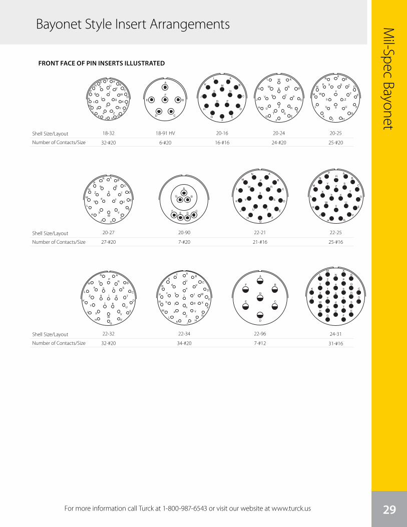
29For more information call Turck at 1-800-987-6543 or visit our website at www.turck.us
Mil-Spec Bayonet
Bayonet Style Insert Arrangements
9
Insert Arrangement 18-75 18-76 18-80 18-91 HV
Service Rating Coax II I, Coax
Number of Contacts 4 3 1 6 2 6
Contact Size 8 Coax 12 Coax 8 Coax 20 8 Coax 20
A
D
C
B
H
G
F
E
A
H GF
E
D
C
B
PN
M
L
K
J
Z
Y
X
WV
U
T
SR
A
Z
YX
W
V
U
TSR
P
N
M
L
K
J HG
F
E
D
C
B
a b
c
A
M
LK
J
H
G
F
E
D
C
B
PN
A
M
L
KJ H G
F
E
D
C
B
TS
RP
NZY
XW
V
U
A
E
D C
B
A
H
G
F
E D
C
B
A
L
K
J
H
G
FE
D
C
B
A
Z Y X
W
V
U
T
S
R
P
N
M
L
KJ
H
G
F
E
D
CB
a
b
c
d
e
fg
A
Z
Y
X
W
VU
TSR
P
N
M
L
KJ H
G
F
E
D
C
B
a
b
c
d
e
f
g
h
j
AH
G
FE
D
C
B
J
A
D
C
B
A
G
F
E
D
C
BH
Amphenol Miniature Cylindricalinsert arrangements
®
front face of pin inserts illustrated
Insert Arrangement 14-AA 16-8 16-23 16-26 16-70
Service Rating I II I I N/A
Number of Contacts 4 8 22 1 26 14 1
Contact Size 12 16 20 16 20 20 12 Coax
Insert Arrangement 16-76 16-99 18-5 18-8 18-11
Service Rating I II I II
Number of Contacts 8 1 5 21 2 5 8 11
Contact Size 20 12* 2 Coax* 20 16 12 12 16
Insert Arrangement 18-30 18-32 18-71 18-72
Service Rating I I II, Coax N/A
Number of Contacts 29 1 32 8 1 10 4
Contact Size 20 16 20 16 8 Coax 20 12 Coax
Flashover1.500 VAC (RMS)
*Contact Positions Optional
AH
B
J
K
DL
R
E
M
F
N
GP
C
A
B
C
MP
L
ND
E
H
F
G
J
K
AD
C B
A
D
C
B
Flashover5,000 VAC (RMS)
A
F
E
D C
B
18-32
32-#20
10
A
M
L
K
J
H
GF
E
D
C
B
S
R P
N
A
Z
Y
XW
V
U
T S
R
P
N
ML
K
J
H
GF
E
D
C
B
a
A
Z
Y
X
W
V U
T
S
R
PN
M
L
KJ H
G
F
E
DC
B
a
b
A
Z
Y
XW
V
U
T
S
R
P
N
M
L
K
J H
G
F
E
D
C
B
a
b
cd
A
Z
YX
WVU
T
S
R
P
N
ML K J
H
G
F
E
D
C
B
ar
p n
m
kj
h
g
fe d
c
b
i
q
A
Z
YX
WV
U
T
S
R
PN
M LK
J
H
G
F
E
D
CB
ats
r
pq
n
mk
j
i
h
g
fe d
c
b
A
P
N
M
LK
J
G
F ED
C
B
H
A
G
FE D
C
B
A
G
D
C
BF
E
A
X
W
V
U T
S
R
P
N
M
L
K
J
HG
F
E
D
C
B
A
ZY
X
WV
U
T
S
RP
N
M
L
K
J
H G
F
E
D
C
B
ab
A
RP
N
M Bb
Sa h c
Z T
L Cjg d
Y
X
K
J
HW
V
GF
UE
Df e
Amphenol Miniature Cylindricalinsert arrangements
®
front face of pin inserts illustrated
Insert Arrangement 20-16 20-24 20-25 20-26
Service Rating II I I I
Number of Contacts 16 24 25 20 6
Contact Size 16 20 20 20 12
Insert Arrangement 20-27 20-39 20-41 20-70
Service Rating I I I Coax
Number of Contacts 27 37 2 41 10 4
Contact Size 20 20 16 20 20 8 Coax
Insert Arrangement 20-90 22-7 22-21 22-25
Service Rating Hi-Voltage Coax II I
Number of Contacts 7 7 21 25
Contact Size 20 8 Coax 16 16
Insert Arrangement 22-32 22-34 22-36 22-41
Service Rating I I I I
Number of Contacts 32 34 36 27 14
Contact Size 20 20 20 20 16
A
Z
Y
X
W
V
U
T
S
R
P
N
M
L
K JH
G
F
E
D
C
B
a
lk
jh
g
f
ed
c
b
ATS
BV
UR
Cf
WP
D
m hge
XN
E
n
l jd
M
L
KJ
a
c
b Z
Y
HG
F
k
AZY
X
W
V
U
T
S
R
PN M L
KJ
H
G
F
E
D
CB
a
t
s
r
q
p
n
m
k
j
i
hg
f
ed
c
b
A
B CD
E
F
GH
JK
LM
N
P
RS T
UV
W
X
Y
Z
a
bc
20-27
27-#20
10
A
M
L
K
J
H
GF
E
D
C
B
S
R P
N
A
Z
Y
XW
V
U
T S
R
P
N
ML
K
J
H
GF
E
D
C
B
a
A
Z
Y
X
W
V U
T
S
R
PN
M
L
KJ H
G
F
E
DC
B
a
b
A
Z
Y
XW
V
U
T
S
R
P
N
M
L
K
J H
G
F
E
D
C
B
a
b
cd
A
Z
YX
WVU
T
S
R
P
N
ML K J
H
G
F
E
D
C
B
ar
p n
m
kj
h
g
fe d
c
b
i
q
A
Z
YX
WV
U
T
S
R
PN
M LK
J
H
G
F
E
D
CB
ats
r
pq
n
mk
j
i
h
g
fe d
c
b
A
P
N
M
LK
J
G
F ED
C
B
H
A
G
FE D
C
B
A
G
D
C
BF
E
A
X
W
V
U T
S
R
P
N
M
L
K
J
HG
F
E
D
C
B
A
ZY
X
WV
U
T
S
RP
N
M
L
K
J
H G
F
E
D
C
B
ab
A
RP
N
M Bb
Sa h c
Z T
L Cjg d
Y
X
K
J
HW
V
GF
UE
Df e
Amphenol Miniature Cylindricalinsert arrangements
®
front face of pin inserts illustrated
Insert Arrangement 20-16 20-24 20-25 20-26
Service Rating II I I I
Number of Contacts 16 24 25 20 6
Contact Size 16 20 20 20 12
Insert Arrangement 20-27 20-39 20-41 20-70
Service Rating I I I Coax
Number of Contacts 27 37 2 41 10 4
Contact Size 20 20 16 20 20 8 Coax
Insert Arrangement 20-90 22-7 22-21 22-25
Service Rating Hi-Voltage Coax II I
Number of Contacts 7 7 21 25
Contact Size 20 8 Coax 16 16
Insert Arrangement 22-32 22-34 22-36 22-41
Service Rating I I I I
Number of Contacts 32 34 36 27 14
Contact Size 20 20 20 20 16
A
Z
Y
X
W
V
U
T
S
R
P
N
M
L
K JH
G
F
E
D
C
B
a
lk
jh
g
f
ed
c
b
ATS
BV
UR
Cf
WP
D
m hge
XN
E
n
l jd
M
L
KJ
a
c
b Z
Y
HG
F
k
AZY
X
W
V
U
T
S
R
PN M L
KJ
H
G
F
E
D
CB
a
t
s
r
q
p
n
m
k
j
i
hg
f
ed
c
b
A
B CD
E
F
GH
JK
LM
N
P
RS T
UV
W
X
Y
Z
a
bc
22-32
32-#20
10
A
M
L
K
J
H
GF
E
D
C
B
S
R P
N
A
Z
Y
XW
V
U
T S
R
P
N
ML
K
J
H
GF
E
D
C
B
a
A
Z
Y
X
W
V U
T
S
R
PN
M
L
KJ H
G
F
E
DC
B
a
b
A
Z
Y
XW
V
U
T
S
R
P
N
M
L
K
J H
G
F
E
D
C
B
a
b
cd
A
Z
YX
WVU
T
S
R
P
N
ML K J
H
G
F
E
D
C
B
ar
p n
m
kj
h
g
fe d
c
b
i
q
A
Z
YX
WV
U
T
S
R
PN
M LK
J
H
G
F
E
D
CB
ats
r
pq
n
mk
j
i
h
g
fe d
c
b
A
P
N
M
LK
J
G
F ED
C
B
H
A
G
FE D
C
B
A
G
D
C
BF
E
A
X
W
V
U T
S
R
P
N
M
L
K
J
HG
F
E
D
C
B
A
ZY
X
WV
U
T
S
RP
N
M
L
K
J
H G
F
E
D
C
B
ab
A
RP
N
M Bb
Sa h c
Z T
L Cjg d
Y
X
K
J
HW
V
GF
UE
Df e
Amphenol Miniature Cylindricalinsert arrangements
®
front face of pin inserts illustrated
Insert Arrangement 20-16 20-24 20-25 20-26
Service Rating II I I I
Number of Contacts 16 24 25 20 6
Contact Size 16 20 20 20 12
Insert Arrangement 20-27 20-39 20-41 20-70
Service Rating I I I Coax
Number of Contacts 27 37 2 41 10 4
Contact Size 20 20 16 20 20 8 Coax
Insert Arrangement 20-90 22-7 22-21 22-25
Service Rating Hi-Voltage Coax II I
Number of Contacts 7 7 21 25
Contact Size 20 8 Coax 16 16
Insert Arrangement 22-32 22-34 22-36 22-41
Service Rating I I I I
Number of Contacts 32 34 36 27 14
Contact Size 20 20 20 20 16
A
Z
Y
X
W
V
U
T
S
R
P
N
M
L
K JH
G
F
E
D
C
B
a
lk
jh
g
f
ed
c
b
ATS
BV
UR
Cf
WP
D
m hge
XN
E
n
l jd
M
L
KJ
a
c
b Z
Y
HG
F
k
AZY
X
W
V
U
T
S
R
PN M L
KJ
H
G
F
E
D
CB
a
t
s
r
q
p
n
m
k
j
i
hg
f
ed
c
b
A
B CD
E
F
GH
JK
LM
N
P
RS T
UV
W
X
Y
Z
a
bc
22-34
34-#20
11
A
Z
YXW
V
UT
S
R
P
N
M
LK J
H
G
F
E
D
CB
a
xw v
ut
s
rq
pn
m
y
k
j
i
hg
f ed
c
b
z
HHGG
FFEE
DD
CCBB
AA
A
G
F
E
D
C
B
H J
A
G
F
E
D
C
B
A
G
F
E
D
C
B
A
X
W
VU
T
S
R
Q
P
Y
N
M
L
K
J
H
G F
E
D
C
B
Z
a
g
f
e
d
c
b
AZ
Y
X
W
V
U
T
S
RP
N M LK
J
H
G
F
E
D
CBa
z
y
x
wvu
t
s
r
p
nm
q
kj
i
h
g
f
e
dc
b
AA
PP
NN
MM
LL
KK
JJ
HHGG
FF
EE
DD
CC BB
a
e
C
B
Dd
f
E
g
F
i
Gh
j
m
p
n
q
rAABB
bX t
y
ZY
A
W
V
U
T
SR
PN M
LK
J
H
z
w
k
vx
s
u
c
Amphenol Miniature Cylindricalinsert arrangements
®
front face of pin inserts illustrated
Insert Arrangement 22-55 22-70 22-71 22-72
Service Rating I I, Coax I, Coax N/A
Number of Contacts 55 13 6 2 7 12 4 3
Contact Size 20 20 8 Coax 20 8 Coax 20 16 8 Coax
Insert Arrangement 22-78 22-96 24-31 24-51
Service Rating Coax II I I
Number of Contacts 7 7 31 47 4
Contact Size 8 Coax 12 for 16 20 12 Coax
# 10 wire
Insert Arrangement 24-61 24-71 24-79
Service Rating I N/A Coax
Number of Contacts 61 45 2 2 1 5
Contact Size 20 20 16 8 Coax 20 8 Coax
Contact Legend
Symbol Contact Size
20
16
12
HV
12 Coax
8 Coax
VK DT P
B
L C
E
H
M
J
F
G
RS
N
A
U
A
V
FE
N
L
T
J
H D
MR
G
P
S
U
C
K B
BC
D
E
F
G
H
K
ij
NP
R
S
T
U
V
W
X
YZ
a A
b
d
e
f
J
M
h
mn
p
q
r
y
t
L
g
BBDD
CC
AA
u c
v
z
s
x
k
w
F
AD
E BC
22-96
7-#12
11
A
Z
YXW
V
UT
S
R
P
N
M
LK J
H
G
F
E
D
CB
a
xw v
ut
s
rq
pn
m
y
k
j
i
hg
f ed
c
b
z
HHGG
FFEE
DD
CCBB
AA
A
G
F
E
D
C
B
H J
A
G
F
E
D
C
B
A
G
F
E
D
C
B
A
X
W
VU
T
S
R
Q
P
Y
N
M
L
K
J
H
G F
E
D
C
B
Z
a
g
f
e
d
c
b
AZ
Y
X
W
V
U
T
S
RP
N M LK
J
H
G
F
E
D
CBa
z
y
x
wvu
t
s
r
p
nm
q
kj
i
h
g
f
e
dc
b
AA
PP
NN
MM
LL
KK
JJ
HHGG
FF
EE
DD
CC BB
a
e
C
B
Dd
f
E
g
F
i
Gh
j
m
p
n
q
rAABB
bX t
y
ZY
A
W
V
U
T
SR
PN M
LK
J
H
z
w
k
vx
s
u
c
Amphenol Miniature Cylindricalinsert arrangements
®
front face of pin inserts illustrated
Insert Arrangement 22-55 22-70 22-71 22-72
Service Rating I I, Coax I, Coax N/A
Number of Contacts 55 13 6 2 7 12 4 3
Contact Size 20 20 8 Coax 20 8 Coax 20 16 8 Coax
Insert Arrangement 22-78 22-96 24-31 24-51
Service Rating Coax II I I
Number of Contacts 7 7 31 47 4
Contact Size 8 Coax 12 for 16 20 12 Coax
# 10 wire
Insert Arrangement 24-61 24-71 24-79
Service Rating I N/A Coax
Number of Contacts 61 45 2 2 1 5
Contact Size 20 20 16 8 Coax 20 8 Coax
Contact Legend
Symbol Contact Size
20
16
12
HV
12 Coax
8 Coax
VK DT P
B
L C
E
H
M
J
F
G
RS
N
A
U
A
V
FE
N
L
T
J
H D
MR
G
P
S
U
C
K B
BC
D
E
F
G
H
K
ij
NP
R
S
T
U
V
W
X
YZ
a A
b
d
e
f
J
M
h
mn
p
q
r
y
t
L
g
BBDD
CC
AA
u c
v
z
s
x
k
w
F
AD
E BC
24-31
31-#16
10
A
M
L
K
J
H
GF
E
D
C
B
S
R P
N
A
Z
Y
XW
V
U
T S
R
P
N
ML
K
J
H
GF
E
D
C
B
a
A
Z
Y
X
W
V U
T
S
R
PN
M
L
KJ H
G
F
E
DC
B
a
b
A
Z
Y
XW
V
U
T
S
R
P
N
M
L
K
J H
G
F
E
D
C
B
a
b
cd
A
Z
YX
WVU
T
S
R
P
N
ML K J
H
G
F
E
D
C
B
ar
p n
m
kj
h
g
fe d
c
b
i
q
A
Z
YX
WV
U
T
S
R
PN
M LK
J
H
G
F
E
D
CB
ats
r
pq
n
mk
j
i
h
g
fe d
c
b
A
P
N
M
LK
J
G
F ED
C
B
H
A
G
FE D
C
B
A
G
D
C
BF
E
A
X
W
V
U T
S
R
P
N
M
L
K
J
HG
F
E
D
C
B
A
ZY
X
WV
U
T
S
RP
N
M
L
K
J
H G
F
E
D
C
B
ab
A
RP
N
M Bb
Sa h c
Z T
L Cjg d
Y
X
K
J
HW
V
GF
UE
Df e
Amphenol Miniature Cylindricalinsert arrangements
®
front face of pin inserts illustrated
Insert Arrangement 20-16 20-24 20-25 20-26
Service Rating II I I I
Number of Contacts 16 24 25 20 6
Contact Size 16 20 20 20 12
Insert Arrangement 20-27 20-39 20-41 20-70
Service Rating I I I Coax
Number of Contacts 27 37 2 41 10 4
Contact Size 20 20 16 20 20 8 Coax
Insert Arrangement 20-90 22-7 22-21 22-25
Service Rating Hi-Voltage Coax II I
Number of Contacts 7 7 21 25
Contact Size 20 8 Coax 16 16
Insert Arrangement 22-32 22-34 22-36 22-41
Service Rating I I I I
Number of Contacts 32 34 36 27 14
Contact Size 20 20 20 20 16
A
Z
Y
X
W
V
U
T
S
R
P
N
M
L
K JH
G
F
E
D
C
B
a
lk
jh
g
f
ed
c
b
ATS
BV
UR
Cf
WP
D
m hge
XN
E
n
l jd
M
L
KJ
a
c
b Z
Y
HG
F
k
AZY
X
W
V
U
T
S
R
PN M L
KJ
H
G
F
E
D
CB
a
t
s
r
q
p
n
m
k
j
i
hg
f
ed
c
b
A
B CD
E
F
GH
JK
LM
N
P
RS T
UV
W
X
Y
Z
a
bc
22-21
21-#16
10
A
M
L
K
J
H
GF
E
D
C
B
S
R P
N
A
Z
Y
XW
V
U
T S
R
P
N
ML
K
J
H
GF
E
D
C
B
a
A
Z
Y
X
W
V U
T
S
R
PN
M
L
KJ H
G
F
E
DC
B
a
b
A
Z
Y
XW
V
U
T
S
R
P
N
M
L
K
J H
G
F
E
D
C
B
a
b
cd
A
Z
YX
WVU
T
S
R
P
N
ML K J
H
G
F
E
D
C
B
ar
p n
m
kj
h
g
fe d
c
b
i
q
A
Z
YX
WV
U
T
S
R
PN
M LK
J
H
G
F
E
D
CB
ats
r
pq
n
mk
j
i
h
g
fe d
c
b
A
P
N
M
LK
J
G
F ED
C
B
H
A
G
FE D
C
B
A
G
D
C
BF
E
A
X
W
V
U T
S
R
P
N
M
L
K
J
HG
F
E
D
C
B
A
ZY
X
WV
U
T
S
RP
N
M
L
K
J
H G
F
E
D
C
B
ab
A
RP
N
M Bb
Sa h c
Z T
L Cjg d
Y
X
K
J
HW
V
GF
UE
Df e
Amphenol Miniature Cylindricalinsert arrangements
®
front face of pin inserts illustrated
Insert Arrangement 20-16 20-24 20-25 20-26
Service Rating II I I I
Number of Contacts 16 24 25 20 6
Contact Size 16 20 20 20 12
Insert Arrangement 20-27 20-39 20-41 20-70
Service Rating I I I Coax
Number of Contacts 27 37 2 41 10 4
Contact Size 20 20 16 20 20 8 Coax
Insert Arrangement 20-90 22-7 22-21 22-25
Service Rating Hi-Voltage Coax II I
Number of Contacts 7 7 21 25
Contact Size 20 8 Coax 16 16
Insert Arrangement 22-32 22-34 22-36 22-41
Service Rating I I I I
Number of Contacts 32 34 36 27 14
Contact Size 20 20 20 20 16
A
Z
Y
X
W
V
U
T
S
R
P
N
M
L
K JH
G
F
E
D
C
B
a
lk
jh
g
f
ed
c
b
ATS
BV
UR
Cf
WP
D
m hge
XN
E
n
l jd
M
L
KJ
a
c
b Z
Y
HG
F
k
AZY
X
W
V
U
T
S
R
PN M L
KJ
H
G
F
E
D
CB
a
t
s
r
q
p
n
m
k
j
i
hg
f
ed
c
b
A
B CD
E
F
GH
JK
LM
N
P
RS T
UV
W
X
Y
Z
a
bc
22-25
25-#16
10
A
M
L
K
J
H
GF
E
D
C
B
S
R P
N
A
Z
Y
XW
V
U
T S
R
P
N
ML
K
J
H
GF
E
D
C
B
a
A
Z
Y
X
W
V U
T
S
R
PN
M
L
KJ H
G
F
E
DC
B
a
b
A
Z
Y
XW
V
U
T
S
R
P
N
M
L
K
J H
G
F
E
D
C
B
a
b
cd
A
Z
YX
WVU
T
S
R
P
N
ML K J
H
G
F
E
D
C
B
ar
p n
m
kj
h
g
fe d
c
b
i
q
A
Z
YX
WV
U
T
S
R
PN
M LK
J
H
G
F
E
D
CB
ats
r
pq
n
mk
j
i
h
g
fe d
c
b
A
P
N
M
LK
J
G
F ED
C
B
H
A
G
FE D
C
B
A
G
D
C
BF
E
A
X
W
V
U T
S
R
P
N
M
L
K
J
HG
F
E
D
C
B
A
ZY
X
WV
U
T
S
RP
N
M
L
K
J
H G
F
E
D
C
B
ab
A
RP
N
M Bb
Sa h c
Z T
L Cjg d
Y
X
K
J
HW
V
GF
UE
Df e
Amphenol Miniature Cylindricalinsert arrangements
®
front face of pin inserts illustrated
Insert Arrangement 20-16 20-24 20-25 20-26
Service Rating II I I I
Number of Contacts 16 24 25 20 6
Contact Size 16 20 20 20 12
Insert Arrangement 20-27 20-39 20-41 20-70
Service Rating I I I Coax
Number of Contacts 27 37 2 41 10 4
Contact Size 20 20 16 20 20 8 Coax
Insert Arrangement 20-90 22-7 22-21 22-25
Service Rating Hi-Voltage Coax II I
Number of Contacts 7 7 21 25
Contact Size 20 8 Coax 16 16
Insert Arrangement 22-32 22-34 22-36 22-41
Service Rating I I I I
Number of Contacts 32 34 36 27 14
Contact Size 20 20 20 20 16
A
Z
Y
X
W
V
U
T
S
R
P
N
M
L
K JH
G
F
E
D
C
B
a
lk
jh
g
f
ed
c
b
ATS
BV
UR
Cf
WP
D
m hge
XN
E
n
l jd
M
L
KJ
a
c
b Z
Y
HG
F
k
AZY
X
W
V
U
T
S
R
PN M L
KJ
H
G
F
E
D
CB
a
t
s
r
q
p
n
m
k
j
i
hg
f
ed
c
b
A
B CD
E
F
GH
JK
LM
N
P
RS T
UV
W
X
Y
Z
a
bc
20-90
7-#20
10
A
M
L
K
J
H
GF
E
D
C
B
S
R P
N
A
Z
Y
XW
V
U
T S
R
P
N
ML
K
J
H
GF
E
D
C
B
a
A
Z
Y
X
W
V U
T
S
R
PN
M
L
KJ H
G
F
E
DC
B
a
b
A
Z
Y
XW
V
U
T
S
R
P
N
M
L
K
J H
G
F
E
D
C
B
a
b
cd
A
Z
YX
WVU
T
S
R
P
N
ML K J
H
G
F
E
D
C
B
ar
p n
m
kj
h
g
fe d
c
b
i
q
A
Z
YX
WV
U
T
S
R
PN
M LK
J
H
G
F
E
D
CB
ats
r
pq
n
mk
j
i
h
g
fe d
c
b
A
P
N
M
LK
J
G
F ED
C
B
H
A
G
FE D
C
B
A
G
D
C
BF
E
A
X
W
V
U T
S
R
P
N
M
L
K
J
HG
F
E
D
C
B
A
ZY
X
WV
U
T
S
RP
N
M
L
K
J
H G
F
E
D
C
B
ab
A
RP
N
M Bb
Sa h c
Z T
L Cjg d
Y
X
K
J
HW
V
GF
UE
Df e
Amphenol Miniature Cylindricalinsert arrangements
®
front face of pin inserts illustrated
Insert Arrangement 20-16 20-24 20-25 20-26
Service Rating II I I I
Number of Contacts 16 24 25 20 6
Contact Size 16 20 20 20 12
Insert Arrangement 20-27 20-39 20-41 20-70
Service Rating I I I Coax
Number of Contacts 27 37 2 41 10 4
Contact Size 20 20 16 20 20 8 Coax
Insert Arrangement 20-90 22-7 22-21 22-25
Service Rating Hi-Voltage Coax II I
Number of Contacts 7 7 21 25
Contact Size 20 8 Coax 16 16
Insert Arrangement 22-32 22-34 22-36 22-41
Service Rating I I I I
Number of Contacts 32 34 36 27 14
Contact Size 20 20 20 20 16
A
Z
Y
X
W
V
U
T
S
R
P
N
M
L
K JH
G
F
E
D
C
B
a
lk
jh
g
f
ed
c
b
ATS
BV
UR
Cf
WP
D
m hge
XN
E
n
l jd
M
L
KJ
a
c
b Z
Y
HG
F
k
AZY
X
W
V
U
T
S
R
PN M L
KJ
H
G
F
E
D
CB
a
t
s
r
q
p
n
m
k
j
i
hg
f
ed
c
b
A
B CD
E
F
GH
JK
LM
N
P
RS T
UV
W
X
Y
Z
a
bc
20-16
16-#16
10
A
M
L
K
J
H
GF
E
D
C
B
S
R P
N
A
Z
Y
XW
V
U
T S
R
P
N
ML
K
J
H
GF
E
D
C
B
a
A
Z
Y
X
W
V U
T
S
R
PN
M
L
KJ H
G
F
E
DC
B
a
b
A
Z
Y
XW
V
U
T
S
R
P
N
M
L
K
J H
G
F
E
D
C
B
a
b
cd
A
Z
YX
WVU
T
S
R
P
N
ML K J
H
G
F
E
D
C
B
ar
p n
m
kj
h
g
fe d
c
b
i
q
A
Z
YX
WV
U
T
S
R
PN
M LK
J
H
G
F
E
D
CB
ats
r
pq
n
mk
j
i
h
g
fe d
c
b
A
P
N
M
LK
J
G
F ED
C
B
H
A
G
FE D
C
B
A
G
D
C
BF
E
A
X
W
V
U T
S
R
P
N
M
L
K
J
HG
F
E
D
C
B
A
ZY
X
WV
U
T
S
RP
N
M
L
K
J
H G
F
E
D
C
B
ab
A
RP
N
M Bb
Sa h c
Z T
L Cjg d
Y
X
K
J
HW
V
GF
UE
Df e
Amphenol Miniature Cylindricalinsert arrangements
®
front face of pin inserts illustrated
Insert Arrangement 20-16 20-24 20-25 20-26
Service Rating II I I I
Number of Contacts 16 24 25 20 6
Contact Size 16 20 20 20 12
Insert Arrangement 20-27 20-39 20-41 20-70
Service Rating I I I Coax
Number of Contacts 27 37 2 41 10 4
Contact Size 20 20 16 20 20 8 Coax
Insert Arrangement 20-90 22-7 22-21 22-25
Service Rating Hi-Voltage Coax II I
Number of Contacts 7 7 21 25
Contact Size 20 8 Coax 16 16
Insert Arrangement 22-32 22-34 22-36 22-41
Service Rating I I I I
Number of Contacts 32 34 36 27 14
Contact Size 20 20 20 20 16
A
Z
Y
X
W
V
U
T
S
R
P
N
M
L
K JH
G
F
E
D
C
B
a
lk
jh
g
f
ed
c
b
ATS
BV
UR
Cf
WP
D
m hge
XN
E
n
l jd
M
L
KJ
a
c
b Z
Y
HG
F
k
AZY
X
W
V
U
T
S
R
PN M L
KJ
H
G
F
E
D
CB
a
t
s
r
q
p
n
m
k
j
i
hg
f
ed
c
b
A
B CD
E
F
GH
JK
LM
N
P
RS T
UV
W
X
Y
Z
a
bc
20-25
25-#20
10
A
M
L
K
J
H
GF
E
D
C
B
S
R P
N
A
Z
Y
XW
V
U
T S
R
P
N
ML
K
J
H
GF
E
D
C
B
a
A
Z
Y
X
W
V U
T
S
R
PN
M
L
KJ H
G
F
E
DC
B
a
b
A
Z
Y
XW
V
U
T
S
R
P
N
M
L
K
J H
G
F
E
D
C
B
a
b
cd
A
Z
YX
WVU
T
S
R
P
N
ML K J
H
G
F
E
D
C
B
ar
p n
m
kj
h
g
fe d
c
b
i
q
A
Z
YX
WV
U
T
S
R
PN
M LK
J
H
G
F
E
D
CB
ats
r
pq
n
mk
j
i
h
g
fe d
c
b
A
P
N
M
LK
J
G
F ED
C
B
H
A
G
FE D
C
B
A
G
D
C
BF
E
A
X
W
V
U T
S
R
P
N
M
L
K
J
HG
F
E
D
C
B
A
ZY
X
WV
U
T
S
RP
N
M
L
K
J
H G
F
E
D
C
B
ab
A
RP
N
M Bb
Sa h c
Z T
L Cjg d
Y
X
K
J
HW
V
GF
UE
Df e
Amphenol Miniature Cylindricalinsert arrangements
®
front face of pin inserts illustrated
Insert Arrangement 20-16 20-24 20-25 20-26
Service Rating II I I I
Number of Contacts 16 24 25 20 6
Contact Size 16 20 20 20 12
Insert Arrangement 20-27 20-39 20-41 20-70
Service Rating I I I Coax
Number of Contacts 27 37 2 41 10 4
Contact Size 20 20 16 20 20 8 Coax
Insert Arrangement 20-90 22-7 22-21 22-25
Service Rating Hi-Voltage Coax II I
Number of Contacts 7 7 21 25
Contact Size 20 8 Coax 16 16
Insert Arrangement 22-32 22-34 22-36 22-41
Service Rating I I I I
Number of Contacts 32 34 36 27 14
Contact Size 20 20 20 20 16
A
Z
Y
X
W
V
U
T
S
R
P
N
M
L
K JH
G
F
E
D
C
B
a
lk
jh
g
f
ed
c
b
ATS
BV
UR
Cf
WP
D
m hge
XN
E
n
l jd
M
L
KJ
a
c
b Z
Y
HG
F
k
AZY
X
W
V
U
T
S
R
PN M L
KJ
H
G
F
E
D
CB
a
t
s
r
q
p
n
m
k
j
i
hg
f
ed
c
b
A
B CD
E
F
GH
JK
LM
N
P
RS T
UV
W
X
Y
Z
a
bc
20-24
24-#20
9
Insert Arrangement 18-75 18-76 18-80 18-91 HV
Service Rating Coax II I, Coax
Number of Contacts 4 3 1 6 2 6
Contact Size 8 Coax 12 Coax 8 Coax 20 8 Coax 20
A
D
C
B
H
G
F
E
A
H GF
E
D
C
B
PN
M
L
K
J
Z
Y
X
WV
U
T
SR
A
Z
YX
W
V
U
TSR
P
N
M
L
K
J HG
F
E
D
C
B
a b
c
A
M
LK
J
H
G
F
E
D
C
B
PN
A
M
L
KJ H G
F
E
D
C
B
TS
RP
NZY
XW
V
U
A
E
D C
B
A
H
G
F
E D
C
B
A
L
K
J
H
G
FE
D
C
B
A
Z Y X
W
V
U
T
S
R
P
N
M
L
KJ
H
G
F
E
D
CB
a
b
c
d
e
fg
A
Z
Y
X
W
VU
TSR
P
N
M
L
KJ H
G
F
E
D
C
B
a
b
c
d
e
f
g
h
j
AH
G
FE
D
C
B
J
A
D
C
B
A
G
F
E
D
C
BH
Amphenol Miniature Cylindricalinsert arrangements
®
front face of pin inserts illustrated
Insert Arrangement 14-AA 16-8 16-23 16-26 16-70
Service Rating I II I I N/A
Number of Contacts 4 8 22 1 26 14 1
Contact Size 12 16 20 16 20 20 12 Coax
Insert Arrangement 16-76 16-99 18-5 18-8 18-11
Service Rating I II I II
Number of Contacts 8 1 5 21 2 5 8 11
Contact Size 20 12* 2 Coax* 20 16 12 12 16
Insert Arrangement 18-30 18-32 18-71 18-72
Service Rating I I II, Coax N/A
Number of Contacts 29 1 32 8 1 10 4
Contact Size 20 16 20 16 8 Coax 20 12 Coax
Flashover1.500 VAC (RMS)
*Contact Positions Optional
AH
B
J
K
DL
R
E
M
F
N
GP
C
A
B
C
MP
L
ND
E
H
F
G
J
K
AD
C B
A
D
C
B
Flashover5,000 VAC (RMS)
A
F
E
D C
B
18-91 HV
6-#20
Shell Size/Layout
Number of Contacts/Size
Shell Size/Layout
Number of Contacts/Size
Shell Size/Layout
Number of Contacts/Size
FRONT FACE OF PIN INSERTS ILLUSTRATED
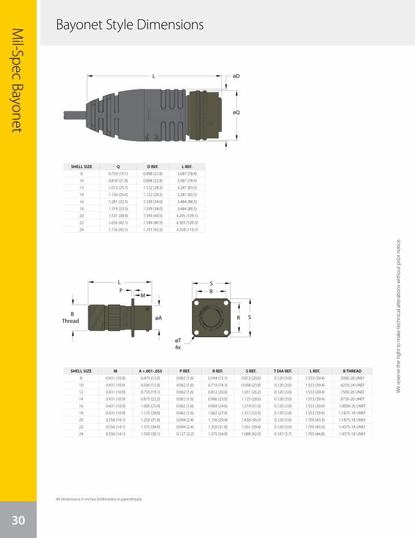
SHELL SIZE Q D REF. L REF.
8 0.750 (19.1) 0.898 (22.8) 3.087 (78.4)
10 0.859 (21.8) 0.898 (22.8) 3.087 (78.4)
12 1.013 (25.7) 1.122 (28.5) 3.287 (83.5)
14 1.156 (29.4) 1.122 (28.5) 3.287 (83.5)
16 1.281 (32.5) 1.339 (34.0) 3.484 (88.5)
18 1.319 (33.5) 1.339 (34.0) 3.484 (88.5)
20 1.531 (38.9) 1.594 (40.5) 4.295 (109.1)
22 1.656 (42.1) 1.594 (40.5) 4.303 (109.3)
24 1.776 (45.1) 1.791 (45.5) 4.358 (110.7)
SHELL SIZE M A +.001-.055 P REF. R REF. S REF. T DIA REF. L REF. B THREAD
8 0.431 (10.9) 0.473 (12.0) 0.062 (1.6) 0.594 (15.1) 0.812 (20.6) 0.120 (3.0) 1.553 (39.4) .5000-28 UNEF
10 0.431 (10.9) 0.590 (15.0) 0.062 (1.6) 0.719 (18.3) 0.938 (23.8) 0.120 (3.0) 1.553 (39.4) .6250-24 UNEF
12 0.431 (10.9) 0.750 (19.1) 0.062 (1.6) 0.812 (20.6) 1.031 (26.2) 0.120 (3.0) 1.553 (39.4) .7500-20 UNEF
14 0.431 (10.9) 0.875 (22.2) 0.062 (1.6) 0.906 (23.0) 1.125 (28.6) 0.120 (3.0) 1.553 (39.4) .8750-20 UNEF
16 0.431 (10.9) 1.000 (25.4) 0.062 (1.6) 0.969 (24.6) 1.219 (31.0) 0.120 (3.0) 1.553 (39.4) 1.0000-20 UNEF
18 0.431 (10.9) 1.125 (28.6) 0.062 (1.6) 1.062 (27.0) 1.312 (33.3) 0.120 (3.0) 1.553 (39.4) 1.1875-18 UNEF
20 0.556 (14.1) 1.250 (31.8) 0.094 (2.4) 1.156 (29.4) 1.438 (36.5) 0.120 (3.0) 1.703 (43.3) 1.1875-18 UNEF
22 0.556 (14.1) 1.375 (34.9) 0.094 (2.4) 1.250 (31.8) 1.561 (39.6) 0.120 (3.0) 1.703 (43.3) 1.4375-18 UNEF
24 0.556 (14.1) 1.500 (38.1) 0.127 (3.2) 1.375 (34.9) 1.688 (42.9) 0.147 (3.7) 1.765 (44.8) 1.4375-18 UNEF
Mil-Spec Bayonet
3030
We
rese
rve
the
right
to m
ake
tech
nica
l alte
ratio
ns w
ithou
t prio
r not
ice.
L
B Thread
S
R
R
S
øT4x
øA
PM
øD
øQ
L
Bayonet Style Dimensions
We reserve the right to m
ake technical alterations without prior notice.
All dimensions in inches (millimeters in parenthesis)
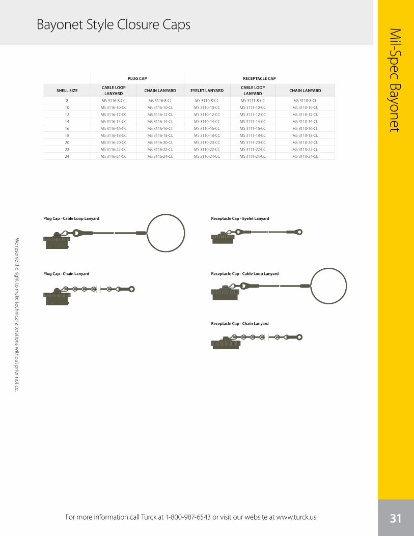
We
rese
rve
the
right
to m
ake
tech
nica
l alte
ratio
ns w
ithou
t prio
r not
ice.
Mil-Spec Bayonet
31
PLUG CAP RECEPTACLE CAP
SHELL SIZECABLE LOOP
LANYARDCHAIN LANYARD EYELET LANYARD
CABLE LOOP LANYARD
CHAIN LANYARD
8 MS 3116-8-CC MS 3116-8-CL MS 3110-8-CC MS 3111-8-CC MS 3110-8-CL
10 MS 3116-10-CC MS 3116-10-CL MS 3110-10-CC MS 3111-10-CC MS 3110-10-CL
12 MS 3116-12-CC MS 3116-12-CL MS 3110-12-CC MS 3111-12-CC MS 3110-12-CL
14 MS 3116-14-CC MS 3116-14-CL MS 3110-14-CC MS 3111-14-CC MS 3110-14-CL
16 MS 3116-16-CC MS 3116-16-CL MS 3110-16-CC MS 3111-16-CC MS 3110-16-CL
18 MS 3116-18-CC MS 3116-18-CL MS 3110-18-CC MS 3111-18-CC MS 3110-18-CL
20 MS 3116-20-CC MS 3116-20-CL MS 3110-20-CC MS 3111-20-CC MS 3110-20-CL
22 MS 3116-22-CC MS 3116-22-CL MS 3110-22-CC MS 3111-22-CC MS 3110-22-CL
24 MS 3116-24-CC MS 3116-24-CL MS 3110-24-CC MS 3111-24-CC MS 3110-24-CL
We reserve the right to m
ake technical alterations without prior notice.
For more information call Turck at 1-800-987-6543 or visit our website at www.turck.us
Plug Cap - Cable Loop Lanyard Receptacle Cap - Eyelet Lanyard
Receptacle Cap - Cable Loop Lanyard
Receptacle Cap - Chain Lanyard
Plug Cap - Chain Lanyard
Bayonet Style Closure Caps

Reverse BayonetTurck’s overmolded GT Series reverse bayonet style connectors replace the threaded coupling in MIL-DTL-5015 connectors with a quick-mating, reverse bayonet lock for improved performance. Overmolded Mil-Spec connectors provide a reduction in labor over traditional field-assembled connectors and diminish the risk of mis-wiring by providing a fully overmolded cordset assembly, allowing you to decrease downtime and save money. Turck’s overmold design technology provides the flexibility to seal the connectors to a wide variety of different cable types. An industry standard for mobile equipment applications—including rail, mass transit and ground vehicles—the reverse bayonet style connector is an ideal option for harsh applications. The reverse bayonet style uses the same shell dimensions, contact layouts, contacts and performance characteristics as the MIL-DTL-5015 threaded connectors; however, the two series do not intermate. The connectors are sealed to withstand moisture, condensation and vibration. Variations in contact layouts allow for just power, just signal or a mix of both contact types.
Applications:• Ships
• Railway equipment
• Mass transit
• Off-road construction equipment
• Telecommunications• Industrial machinery• Power generators• Applications involving sensors or motion control
32
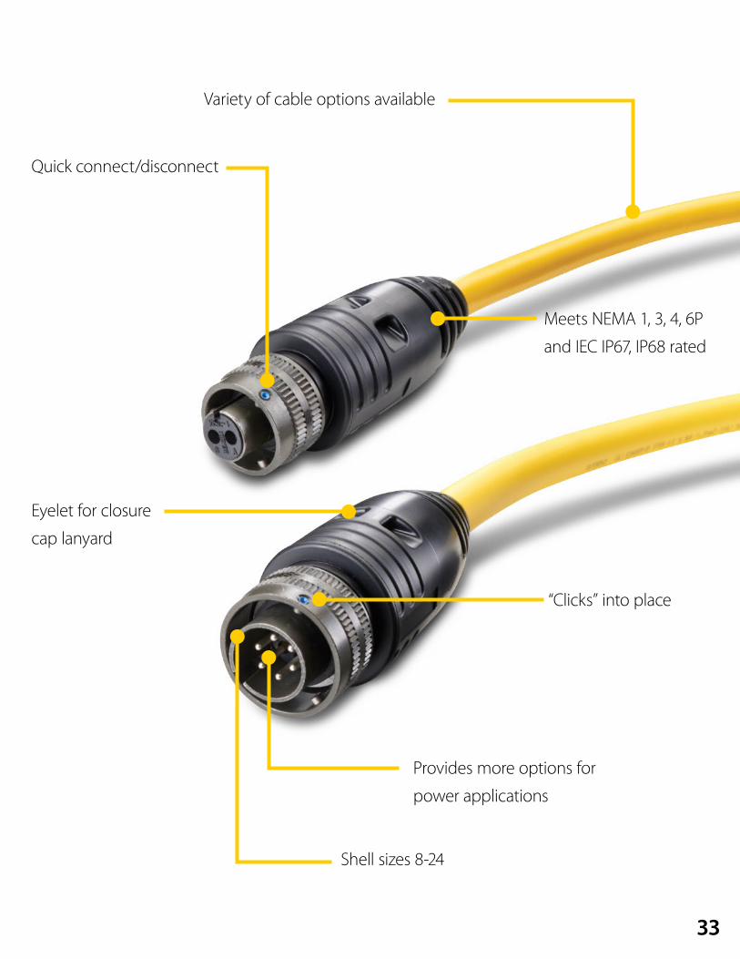
Variety of cable options available
Quick connect/disconnect
“Clicks” into place
Meets NEMA 1, 3, 4, 6P
and IEC IP67, IP68 rated
Eyelet for closure
cap lanyard
Shell sizes 8-24
Provides more options for
power applications
33
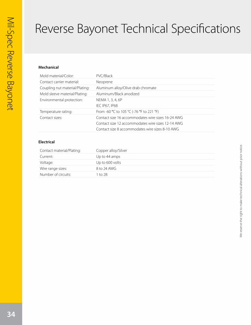
Mil-Spec Reverse Bayonet
34
Reverse Bayonet Technical Specifications
Mechanical
Electrical
Mold material/Color: PVC/BlackContact carrier material: NeopreneCoupling nut material/Plating: Aluminum alloy/Olive drab chromateMold sleeve material/Plating: Aluminum/Black anodizedEnvironmental protection: NEMA 1, 3, 4, 6P
IEC IP67, IP68Temperature rating: From -60 °C to 105 °C (-76 °F to 221 °F)Contact sizes: Contact size 16 accommodates wire sizes 16-24 AWG
Contact size 12 accommodates wire sizes 12-14 AWGContact size 8 accommodates wire sizes 8-10 AWG
Contact material/Plating: Copper alloy/SilverCurrent: Up to 44 ampsVoltage: Up to 600 voltsWire range sizes: 8 to 24 AWGNumber of circuits: 1 to 28
We
rese
rve
the
right
to m
ake
tech
nica
l alte
ratio
ns w
ithou
t prio
r not
ice.
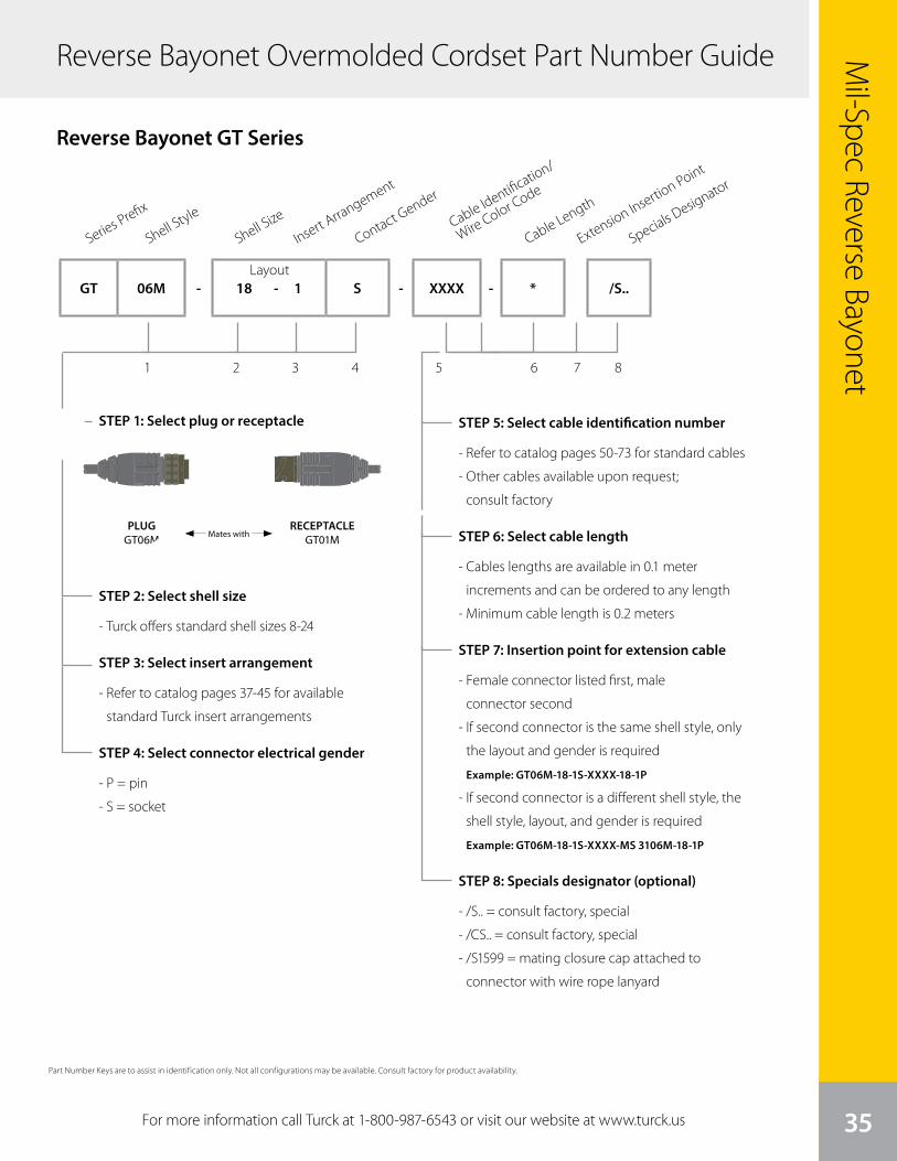
We
rese
rve
the
right
to m
ake
tech
nica
l alte
ratio
ns w
ithou
t prio
r not
ice.
Mil-Spec Reverse Bayonet
35For more information call Turck at 1-800-987-6543 or visit our website at www.turck.us
Reverse Bayonet Overmolded Cordset Part Number Guide
STEP 1: Select plug or receptacle
Series Prefix
1 2 3 4 5 6 7 8
Shell Style
Shell Size
Insert Arrangement
Contact Gender
Cable Length
GT 06M - 18 - 1 S - XXXX - * /S..
Reverse Bayonet GT Series
Layout
Specials Designator
Extension Insertion Point
STEP 2: Select shell size
- Turck offers standard shell sizes 8-24
STEP 3: Select insert arrangement
- Refer to catalog pages 37-45 for available
standard Turck insert arrangements
STEP 4: Select connector electrical gender
- P = pin
- S = socket
STEP 5: Select cable identification number
- Refer to catalog pages 50-73 for standard cables
- Other cables available upon request;
consult factory
STEP 6: Select cable length
- Cables lengths are available in 0.1 meter
increments and can be ordered to any length
- Minimum cable length is 0.2 meters
STEP 7: Insertion point for extension cable
- Female connector listed first, male
connector second
- If second connector is the same shell style, only
the layout and gender is required
Example: GT06M-18-1S-XXXX-18-1P
- If second connector is a different shell style, the
shell style, layout, and gender is required
Example: GT06M-18-1S-XXXX-MS 3106M-18-1P
STEP 8: Specials designator (optional)
- /S.. = consult factory, special
- /CS.. = consult factory, special
- /S1599 = mating closure cap attached to
connector with wire rope lanyard
Cable Identification/
Wire Color Code
Part Number Keys are to assist in identification only. Not all configurations may be available. Consult factory for product availability.
PLUGGT06M Mates with
RECEPTACLEGT01M

Mil-Spec Reverse Bayonet
36
Reverse Bayonet Receptacle Part Number Guide
STEP 1: Select receptacle style
1 2 3 4 5
Reverse Bayonet GT Series
STEP 5: Select connector electrical gender
- P = pin
- S = socket
STEP 6: Wiring color code (optional)
- (blank) = standard wiring color code
- Use same 4 digit code from cordset to get
matching pinout
STEP 7: Select wire lead length
- Wire lead lengths are available in 0.1 meter
increments and can be ordered to any length
- Minimum wire lead length is 0.1 meters
STEP 8: Specials designator (optional)
- /S.. = consult factory, special
- /CS.. = consult factory, special
- /S717 = receptacle assembled with potted in
jacketed cable
Series Prefix
6 7 8
Shell Style
EndbellShell Size
Insert Arrangement
Contact Gender
Wire Length
Wiring Color Code
Specials Designator
GT 00 A - 18 - 1 S - XXXX * /S..Layout
STEP 2: Select endbell
- A = standard metal, potted
- (blank) = no endbell, no potting
STEP 3: Select shell size
- Turck offers standard shell sizes 8-24
STEP 4: Select insert arrangement
- Refer to catalog pages 37-45 for available
standard Turck insert arrangements
GT00
Wall mount flange with accessory threads
Box mount flange with no accessory threads
GT02
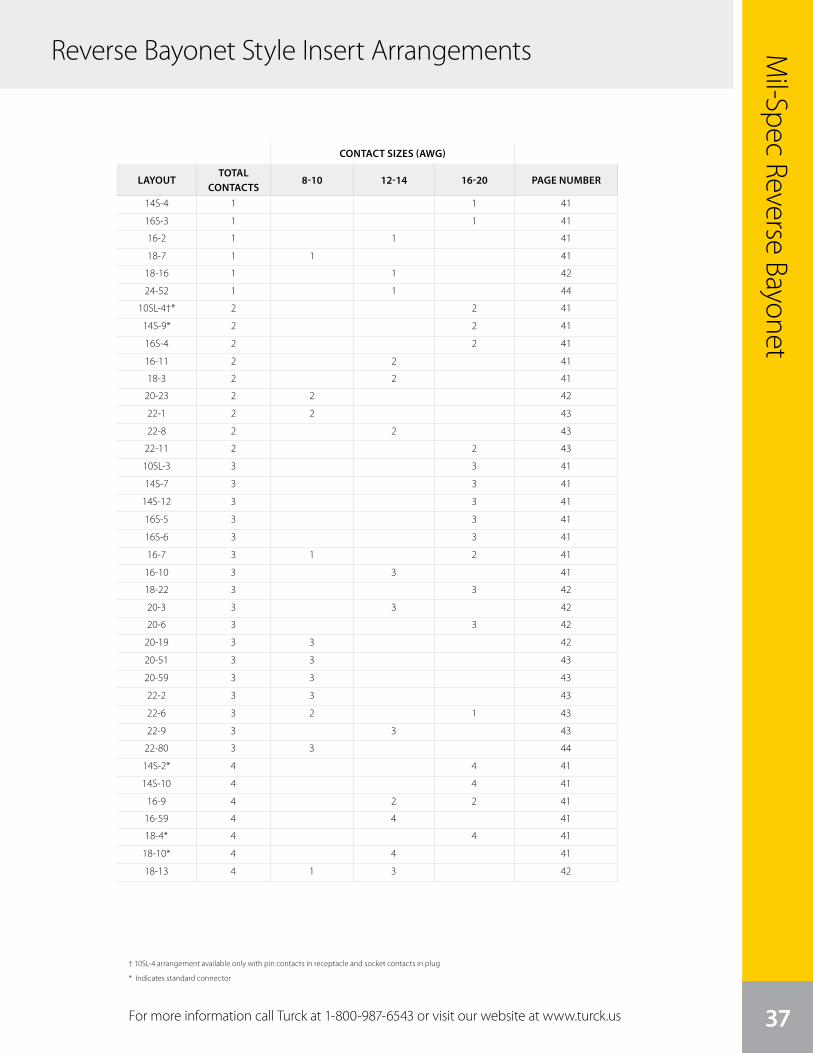
Specials Designator
Mil-Spec Reverse Bayonet
37For more information call Turck at 1-800-987-6543 or visit our website at www.turck.us
CONTACT SIZES (AWG)
LAYOUTTOTAL
CONTACTS8-10 12-14 16-20 PAGE NUMBER
14S-4 1 1 41
16S-3 1 1 41
16-2 1 1 41
18-7 1 1 41
18-16 1 1 42
24-52 1 1 44
10SL-4†* 2 2 41
14S-9* 2 2 41
16S-4 2 2 41
16-11 2 2 41
18-3 2 2 41
20-23 2 2 42
22-1 2 2 43
22-8 2 2 43
22-11 2 2 43
10SL-3 3 3 41
14S-7 3 3 41
14S-12 3 3 41
16S-5 3 3 41
16S-6 3 3 41
16-7 3 1 2 41
16-10 3 3 41
18-22 3 3 42
20-3 3 3 42
20-6 3 3 42
20-19 3 3 42
20-51 3 3 43
20-59 3 3 43
22-2 3 3 43
22-6 3 2 1 43
22-9 3 3 43
22-80 3 3 44
14S-2* 4 4 41
14S-10 4 4 41
16-9 4 2 2 41
16-59 4 4 41
18-4* 4 4 41
18-10* 4 4 41
18-13 4 1 3 42
† 10SL-4 arrangement available only with pin contacts in receptacle and socket contacts in plug
* Indicates standard connector
Reverse Bayonet Style Insert Arrangements
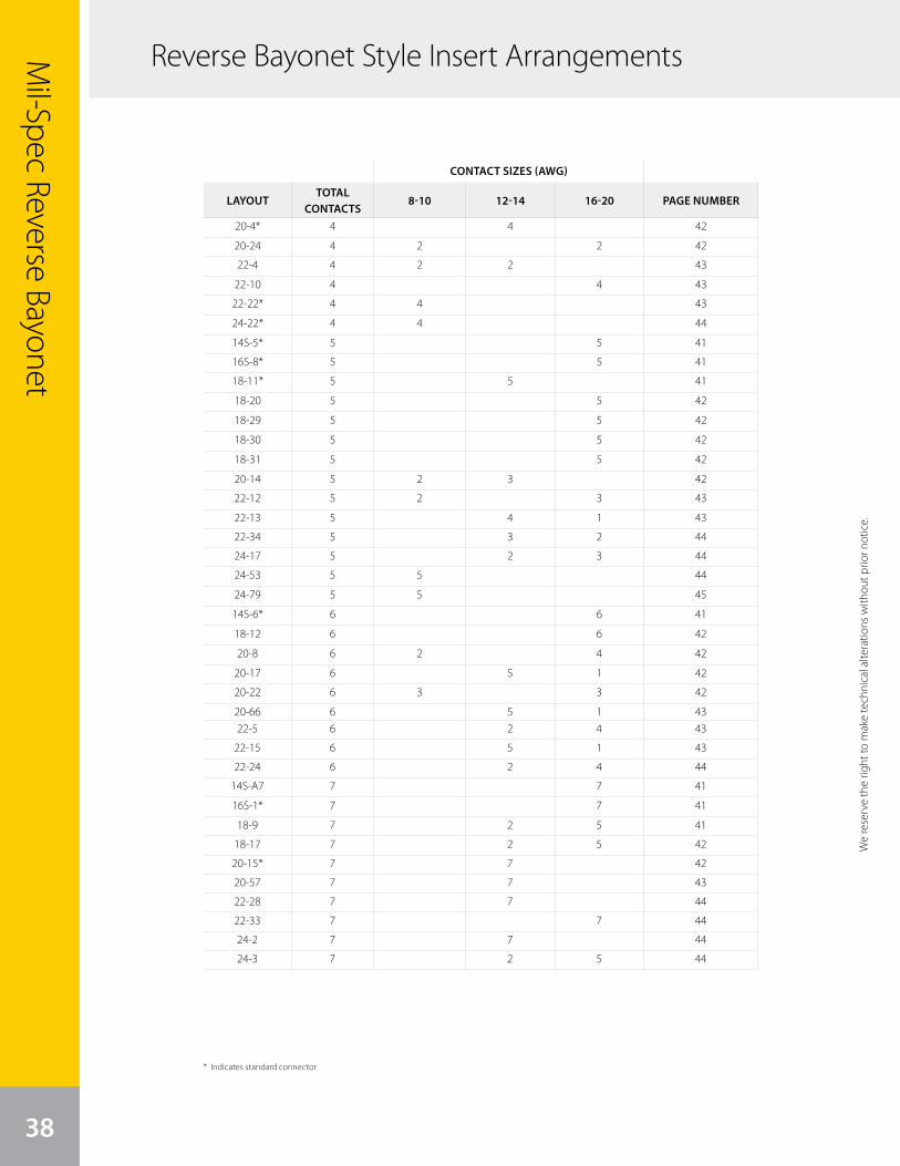
38
Mil-Spec Reverse Bayonet
CONTACT SIZES (AWG)
LAYOUTTOTAL
CONTACTS8-10 12-14 16-20 PAGE NUMBER
20-4* 4 4 42
20-24 4 2 2 42
22-4 4 2 2 43
22-10 4 4 43
22-22* 4 4 43
24-22* 4 4 44
14S-5* 5 5 41
16S-8* 5 5 41
18-11* 5 5 41
18-20 5 5 42
18-29 5 5 42
18-30 5 5 42
18-31 5 5 42
20-14 5 2 3 42
22-12 5 2 3 43
22-13 5 4 1 43
22-34 5 3 2 44
24-17 5 2 3 44
24-53 5 5 44
24-79 5 5 45
14S-6* 6 6 41
18-12 6 6 42
20-8 6 2 4 42
20-17 6 5 1 42
20-22 6 3 3 42
20-66 6 5 1 4322-5 6 2 4 43
22-15 6 5 1 43
22-24 6 2 4 44
14S-A7 7 7 41
16S-1* 7 7 41
18-9 7 2 5 41
18-17 7 2 5 42
20-15* 7 7 42
20-57 7 7 43
22-28 7 7 44
22-33 7 7 44
24-2 7 7 44
24-3 7 2 5 44
* Indicates standard connector
We
rese
rve
the
right
to m
ake
tech
nica
l alte
ratio
ns w
ithou
t prio
r not
ice.
Reverse Bayonet Style Insert Arrangements
We reserve the right to m
ake technical alterations without prior notice.
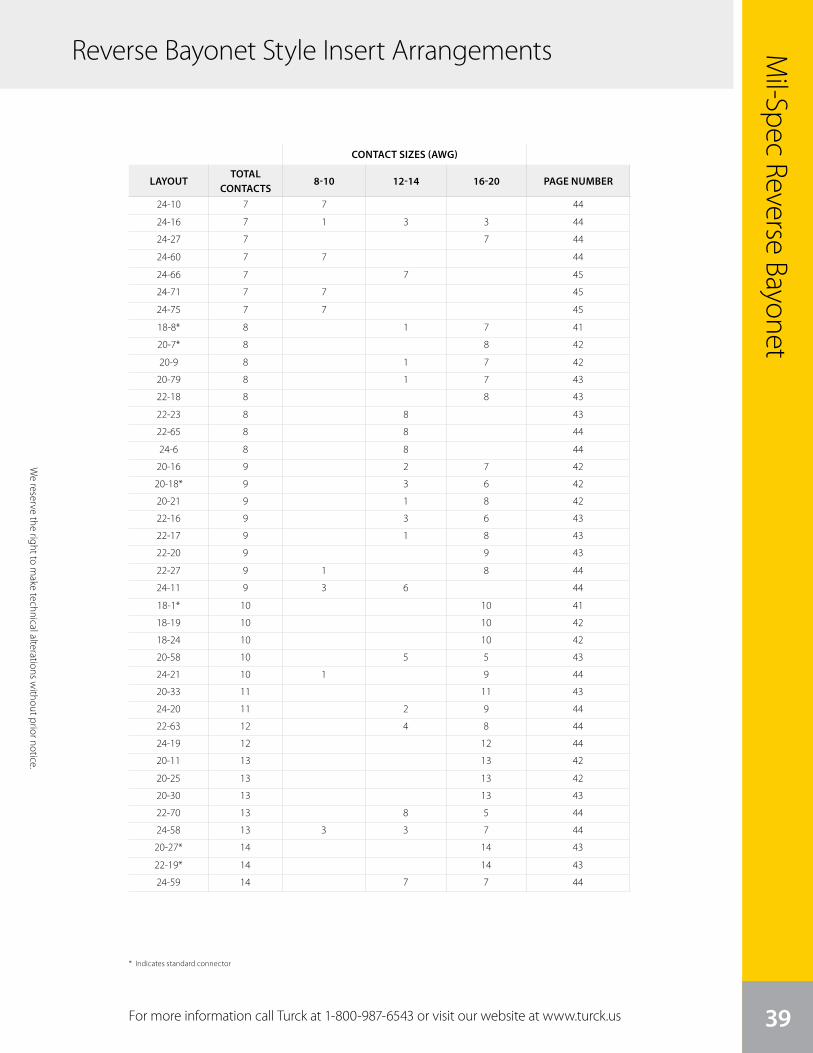
We
rese
rve
the
right
to m
ake
tech
nica
l alte
ratio
ns w
ithou
t prio
r not
ice.
39
Mil-Spec Reverse Bayonet
For more information call Turck at 1-800-987-6543 or visit our website at www.turck.us
We reserve the right to m
ake technical alterations without prior notice.
CONTACT SIZES (AWG)
LAYOUTTOTAL
CONTACTS8-10 12-14 16-20 PAGE NUMBER
24-10 7 7 44
24-16 7 1 3 3 44
24-27 7 7 44
24-60 7 7 44
24-66 7 7 45
24-71 7 7 45
24-75 7 7 45
18-8* 8 1 7 41
20-7* 8 8 42
20-9 8 1 7 42
20-79 8 1 7 43
22-18 8 8 43
22-23 8 8 43
22-65 8 8 44
24-6 8 8 44
20-16 9 2 7 42
20-18* 9 3 6 42
20-21 9 1 8 42
22-16 9 3 6 43
22-17 9 1 8 43
22-20 9 9 43
22-27 9 1 8 44
24-11 9 3 6 44
18-1* 10 10 41
18-19 10 10 42
18-24 10 10 42
20-58 10 5 5 43
24-21 10 1 9 44
20-33 11 11 43
24-20 11 2 9 44
22-63 12 4 8 44
24-19 12 12 44
20-11 13 13 42
20-25 13 13 42
20-30 13 13 43
22-70 13 8 5 44
24-58 13 3 3 7 44
20-27* 14 14 43
22-19* 14 14 43
24-59 14 7 7 44
* Indicates standard connector
Reverse Bayonet Style Insert Arrangements
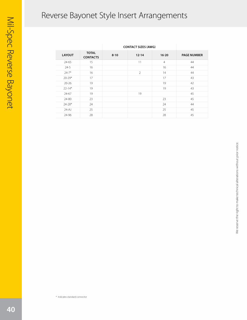
40
Mil-Spec Reverse Bayonet
CONTACT SIZES (AWG)
LAYOUTTOTAL
CONTACTS8-10 12-14 16-20 PAGE NUMBER
24-65 15 11 4 44
24-5 16 16 44
24-7* 16 2 14 44
20-29* 17 17 43
20-26 19 19 42
22-14* 19 19 43
24-67 19 19 45
24-80 23 23 45
24-28* 24 24 44
24-AJ 25 25 45
24-96 28 28 45
We
rese
rve
the
right
to m
ake
tech
nica
l alte
ratio
ns w
ithou
t prio
r not
ice.
* Indicates standard connector
Reverse Bayonet Style Insert Arrangements
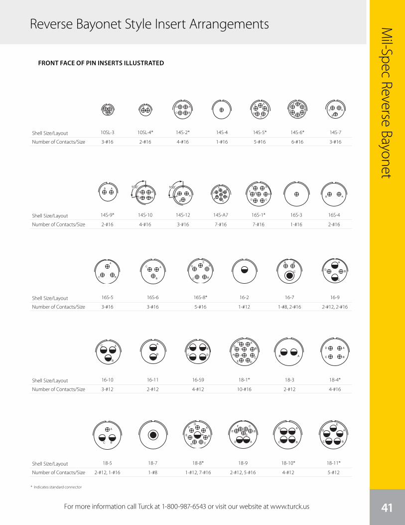
We
rese
rve
the
right
to m
ake
tech
nica
l alte
ratio
ns w
ithou
t prio
r not
ice.
41
Mil-Spec Reverse Bayonet
For more information call Turck at 1-800-987-6543 or visit our website at www.turck.us
Reverse Bayonet Style Insert Arrangements
Shell Size/Layout
Number of Contacts/Size
Shell Size/Layout
Number of Contacts/Size
Shell Size/Layout
Number of Contacts/Size
Shell Size/Layout
Number of Contacts/Size
6
ABC
AB A
BC
DA
B
C
D
E
F A
B
CD
E A
B
C
AB100˚
A
BC
D
100˚
A
B
C
A
B
CD
E
F
G
AB
A
BC
A
B
C A
BC
D
E A B
C
A
B
C
D
A
F
ED
C
BG
front face of pin insert or rear face of socket insert illustrated
GT Seriescontact arrangements
Insert Arrangement 10SL-3 10SL-4 14S-2 14S-4 14S-5
Service Rating A A Inst. D Inst.
Number of Contacts 3 2 4 1 5
Contact Size 16 16 16 16 16
Insert Arrangement 14S-6 14S-7 14S-9 14S-10 14S-12
Service Rating Inst. A A Inst. A
Number of Contacts 6 3 2 4 3
Contact Size 16 16 16 16 16
Insert Arrangement 14S-A7 16S-1 16S-3 16S-4 16S-5
Service Rating A A B D A
Number of Contacts 7 7 1 2 3
Contact Size 16 16 16 16 16
Insert Arrangement 16S-6 16S-8 16-2 16-7 16-9
Service Rating A A E A A
Number of Contacts 3 5 1 1 2 2 2
Contact Size 16 16 12 8 16 12 16
CONTACT LEGEND 16 12 8 4 0
Front ofSocket Insert
Front ofSocket Insert
100° Rotationof 14S-2
100° Rotationof 14S-7
10SL-3
3-#16
6
ABC
AB A
BC
DA
B
C
D
E
F A
B
CD
E A
B
C
AB100˚
A
BC
D
100˚
A
B
C
A
B
CD
E
F
G
AB
A
BC
A
B
C A
BC
D
E A B
C
A
B
C
D
A
F
ED
C
BG
front face of pin insert or rear face of socket insert illustrated
GT Seriescontact arrangements
Insert Arrangement 10SL-3 10SL-4 14S-2 14S-4 14S-5
Service Rating A A Inst. D Inst.
Number of Contacts 3 2 4 1 5
Contact Size 16 16 16 16 16
Insert Arrangement 14S-6 14S-7 14S-9 14S-10 14S-12
Service Rating Inst. A A Inst. A
Number of Contacts 6 3 2 4 3
Contact Size 16 16 16 16 16
Insert Arrangement 14S-A7 16S-1 16S-3 16S-4 16S-5
Service Rating A A B D A
Number of Contacts 7 7 1 2 3
Contact Size 16 16 16 16 16
Insert Arrangement 16S-6 16S-8 16-2 16-7 16-9
Service Rating A A E A A
Number of Contacts 3 5 1 1 2 2 2
Contact Size 16 16 12 8 16 12 16
CONTACT LEGEND 16 12 8 4 0
Front ofSocket Insert
Front ofSocket Insert
100° Rotationof 14S-2
100° Rotationof 14S-714S-9*
2-#16
6
ABC
AB A
BC
DA
B
C
D
E
F A
B
CD
E A
B
C
AB100˚
A
BC
D
100˚
A
B
C
A
B
CD
E
F
G
AB
A
BC
A
B
C A
BC
D
E A B
C
A
B
C
D
A
F
ED
C
BG
front face of pin insert or rear face of socket insert illustrated
GT Seriescontact arrangements
Insert Arrangement 10SL-3 10SL-4 14S-2 14S-4 14S-5
Service Rating A A Inst. D Inst.
Number of Contacts 3 2 4 1 5
Contact Size 16 16 16 16 16
Insert Arrangement 14S-6 14S-7 14S-9 14S-10 14S-12
Service Rating Inst. A A Inst. A
Number of Contacts 6 3 2 4 3
Contact Size 16 16 16 16 16
Insert Arrangement 14S-A7 16S-1 16S-3 16S-4 16S-5
Service Rating A A B D A
Number of Contacts 7 7 1 2 3
Contact Size 16 16 16 16 16
Insert Arrangement 16S-6 16S-8 16-2 16-7 16-9
Service Rating A A E A A
Number of Contacts 3 5 1 1 2 2 2
Contact Size 16 16 12 8 16 12 16
CONTACT LEGEND 16 12 8 4 0
Front ofSocket Insert
Front ofSocket Insert
100° Rotationof 14S-2
100° Rotationof 14S-7
16S-5
3-#16
7
A
B
AB
AB
A
BC
DA
BC
A
B
CD
E
FG
H
A
B
C
D
E
F
G
A
BC
DA
BC
D
E
A
B
C
D
EF
A
B
C
D
A
B
A
B
C
D
100˚
A
B
C
D
E
F
G
A
B CD E F G
H
K
J
A B
CD
E
front face of pin insert or rear face of socket insert illustrated
GT Seriescontact arrangements
Insert Arrangement 16-10 16-11 16-12 16-13 16-59
Service Rating A A A A A
Number of Contacts 3 2 1 2* 4
Contact Size 12 12 4 12 12
Insert Arrangement 18-1 18-3 18-4 18-5 18-6 18-7
Service Rating B, C, F, G = A; Bal. = Inst. D D D D B
Number of Contacts 10 2 4 2 1 1 1
Contact Size 16 12 16 12 16 4 8
Insert Arrangement 18-8 18-9 18-10 18-11 18-12 18-13
Service Rating A Inst. A A A A
Number of Contacts 1 7 2 5 4 5 6 1 3
Contact Size 12 16 12 16 12 12 16 8 12
Insert Arrangement 18-14 18-15 18-16 18-17 18-19 18-20
Service Rating A A C Inst. A A
Number of Contacts 1 1 4** 1 2 5 10 5
Contact Size 4 16 12 12 12 16 16 16
CONTACT LEGEND 16 12 8 4 0
* A = Iron; B = Constantan**A, C = Iron; B, D = Constantan
100° Rotationof 18-9
A
B
C
DE
F
G
H
I
J
B
C AA B
C D
16-10
3-#12
6
ABC
AB A
BC
DA
B
C
D
E
F A
B
CD
E A
B
C
AB100˚
A
BC
D
100˚
A
B
C
A
B
CD
E
F
G
AB
A
BC
A
B
C A
BC
D
E A B
C
A
B
C
D
A
F
ED
C
BG
front face of pin insert or rear face of socket insert illustrated
GT Seriescontact arrangements
Insert Arrangement 10SL-3 10SL-4 14S-2 14S-4 14S-5
Service Rating A A Inst. D Inst.
Number of Contacts 3 2 4 1 5
Contact Size 16 16 16 16 16
Insert Arrangement 14S-6 14S-7 14S-9 14S-10 14S-12
Service Rating Inst. A A Inst. A
Number of Contacts 6 3 2 4 3
Contact Size 16 16 16 16 16
Insert Arrangement 14S-A7 16S-1 16S-3 16S-4 16S-5
Service Rating A A B D A
Number of Contacts 7 7 1 2 3
Contact Size 16 16 16 16 16
Insert Arrangement 16S-6 16S-8 16-2 16-7 16-9
Service Rating A A E A A
Number of Contacts 3 5 1 1 2 2 2
Contact Size 16 16 12 8 16 12 16
CONTACT LEGEND 16 12 8 4 0
Front ofSocket Insert
Front ofSocket Insert
100° Rotationof 14S-2
100° Rotationof 14S-7
16S-6
3-#16
7
A
B
AB
AB
A
BC
DA
BC
A
B
CD
E
FG
H
A
B
C
D
E
F
G
A
BC
DA
BC
D
E
A
B
C
D
EF
A
B
C
D
A
B
A
B
C
D
100˚
A
B
C
D
E
F
G
A
B CD E F G
H
K
J
A B
CD
E
front face of pin insert or rear face of socket insert illustrated
GT Seriescontact arrangements
Insert Arrangement 16-10 16-11 16-12 16-13 16-59
Service Rating A A A A A
Number of Contacts 3 2 1 2* 4
Contact Size 12 12 4 12 12
Insert Arrangement 18-1 18-3 18-4 18-5 18-6 18-7
Service Rating B, C, F, G = A; Bal. = Inst. D D D D B
Number of Contacts 10 2 4 2 1 1 1
Contact Size 16 12 16 12 16 4 8
Insert Arrangement 18-8 18-9 18-10 18-11 18-12 18-13
Service Rating A Inst. A A A A
Number of Contacts 1 7 2 5 4 5 6 1 3
Contact Size 12 16 12 16 12 12 16 8 12
Insert Arrangement 18-14 18-15 18-16 18-17 18-19 18-20
Service Rating A A C Inst. A A
Number of Contacts 1 1 4** 1 2 5 10 5
Contact Size 4 16 12 12 12 16 16 16
CONTACT LEGEND 16 12 8 4 0
* A = Iron; B = Constantan**A, C = Iron; B, D = Constantan
100° Rotationof 18-9
A
B
C
DE
F
G
H
I
J
B
C AA B
C D
16-11
2-#12
7
A
B
AB
AB
A
BC
DA
BC
A
B
CD
E
FG
H
A
B
C
D
E
F
G
A
BC
DA
BC
D
E
A
B
C
D
EF
A
B
C
D
A
B
A
B
C
D
100˚
A
B
C
D
E
F
G
A
B CD E F G
H
K
J
A B
CD
E
front face of pin insert or rear face of socket insert illustrated
GT Seriescontact arrangements
Insert Arrangement 16-10 16-11 16-12 16-13 16-59
Service Rating A A A A A
Number of Contacts 3 2 1 2* 4
Contact Size 12 12 4 12 12
Insert Arrangement 18-1 18-3 18-4 18-5 18-6 18-7
Service Rating B, C, F, G = A; Bal. = Inst. D D D D B
Number of Contacts 10 2 4 2 1 1 1
Contact Size 16 12 16 12 16 4 8
Insert Arrangement 18-8 18-9 18-10 18-11 18-12 18-13
Service Rating A Inst. A A A A
Number of Contacts 1 7 2 5 4 5 6 1 3
Contact Size 12 16 12 16 12 12 16 8 12
Insert Arrangement 18-14 18-15 18-16 18-17 18-19 18-20
Service Rating A A C Inst. A A
Number of Contacts 1 1 4** 1 2 5 10 5
Contact Size 4 16 12 12 12 16 16 16
CONTACT LEGEND 16 12 8 4 0
* A = Iron; B = Constantan**A, C = Iron; B, D = Constantan
100° Rotationof 18-9
A
B
C
DE
F
G
H
I
J
B
C AA B
C D
16-59
4-#12
7
A
B
AB
AB
A
BC
DA
BC
A
B
CD
E
FG
H
A
B
C
D
E
F
G
A
BC
DA
BC
D
E
A
B
C
D
EF
A
B
C
D
A
B
A
B
C
D
100˚
A
B
C
D
E
F
G
A
B CD E F G
H
K
J
A B
CD
E
front face of pin insert or rear face of socket insert illustrated
GT Seriescontact arrangements
Insert Arrangement 16-10 16-11 16-12 16-13 16-59
Service Rating A A A A A
Number of Contacts 3 2 1 2* 4
Contact Size 12 12 4 12 12
Insert Arrangement 18-1 18-3 18-4 18-5 18-6 18-7
Service Rating B, C, F, G = A; Bal. = Inst. D D D D B
Number of Contacts 10 2 4 2 1 1 1
Contact Size 16 12 16 12 16 4 8
Insert Arrangement 18-8 18-9 18-10 18-11 18-12 18-13
Service Rating A Inst. A A A A
Number of Contacts 1 7 2 5 4 5 6 1 3
Contact Size 12 16 12 16 12 12 16 8 12
Insert Arrangement 18-14 18-15 18-16 18-17 18-19 18-20
Service Rating A A C Inst. A A
Number of Contacts 1 1 4** 1 2 5 10 5
Contact Size 4 16 12 12 12 16 16 16
CONTACT LEGEND 16 12 8 4 0
* A = Iron; B = Constantan**A, C = Iron; B, D = Constantan
100° Rotationof 18-9
A
B
C
DE
F
G
H
I
J
B
C AA B
C D
18-1*
10-#16
7
A
B
AB
AB
A
BC
DA
BC
A
B
CD
E
FG
H
A
B
C
D
E
F
G
A
BC
DA
BC
D
E
A
B
C
D
EF
A
B
C
D
A
B
A
B
C
D
100˚
A
B
C
D
E
F
G
A
B CD E F G
H
K
J
A B
CD
E
front face of pin insert or rear face of socket insert illustrated
GT Seriescontact arrangements
Insert Arrangement 16-10 16-11 16-12 16-13 16-59
Service Rating A A A A A
Number of Contacts 3 2 1 2* 4
Contact Size 12 12 4 12 12
Insert Arrangement 18-1 18-3 18-4 18-5 18-6 18-7
Service Rating B, C, F, G = A; Bal. = Inst. D D D D B
Number of Contacts 10 2 4 2 1 1 1
Contact Size 16 12 16 12 16 4 8
Insert Arrangement 18-8 18-9 18-10 18-11 18-12 18-13
Service Rating A Inst. A A A A
Number of Contacts 1 7 2 5 4 5 6 1 3
Contact Size 12 16 12 16 12 12 16 8 12
Insert Arrangement 18-14 18-15 18-16 18-17 18-19 18-20
Service Rating A A C Inst. A A
Number of Contacts 1 1 4** 1 2 5 10 5
Contact Size 4 16 12 12 12 16 16 16
CONTACT LEGEND 16 12 8 4 0
* A = Iron; B = Constantan**A, C = Iron; B, D = Constantan
100° Rotationof 18-9
A
B
C
DE
F
G
H
I
J
B
C AA B
C D
18-3
2-#12
7
A
B
AB
AB
A
BC
DA
BC
A
B
CD
E
FG
H
A
B
C
D
E
F
G
A
BC
DA
BC
D
E
A
B
C
D
EF
A
B
C
D
A
B
A
B
C
D
100˚
A
B
C
D
E
F
G
A
B CD E F G
H
K
J
A B
CD
E
front face of pin insert or rear face of socket insert illustrated
GT Seriescontact arrangements
Insert Arrangement 16-10 16-11 16-12 16-13 16-59
Service Rating A A A A A
Number of Contacts 3 2 1 2* 4
Contact Size 12 12 4 12 12
Insert Arrangement 18-1 18-3 18-4 18-5 18-6 18-7
Service Rating B, C, F, G = A; Bal. = Inst. D D D D B
Number of Contacts 10 2 4 2 1 1 1
Contact Size 16 12 16 12 16 4 8
Insert Arrangement 18-8 18-9 18-10 18-11 18-12 18-13
Service Rating A Inst. A A A A
Number of Contacts 1 7 2 5 4 5 6 1 3
Contact Size 12 16 12 16 12 12 16 8 12
Insert Arrangement 18-14 18-15 18-16 18-17 18-19 18-20
Service Rating A A C Inst. A A
Number of Contacts 1 1 4** 1 2 5 10 5
Contact Size 4 16 12 12 12 16 16 16
CONTACT LEGEND 16 12 8 4 0
* A = Iron; B = Constantan**A, C = Iron; B, D = Constantan
100° Rotationof 18-9
A
B
C
DE
F
G
H
I
J
B
C AA B
C D
18-4*
4-#16
6
ABC
AB A
BC
DA
B
C
D
E
F A
B
CD
E A
B
C
AB100˚
A
BC
D
100˚
A
B
C
A
B
CD
E
F
G
AB
A
BC
A
B
C A
BC
D
E A B
C
A
B
C
D
A
F
ED
C
BG
front face of pin insert or rear face of socket insert illustrated
GT Seriescontact arrangements
Insert Arrangement 10SL-3 10SL-4 14S-2 14S-4 14S-5
Service Rating A A Inst. D Inst.
Number of Contacts 3 2 4 1 5
Contact Size 16 16 16 16 16
Insert Arrangement 14S-6 14S-7 14S-9 14S-10 14S-12
Service Rating Inst. A A Inst. A
Number of Contacts 6 3 2 4 3
Contact Size 16 16 16 16 16
Insert Arrangement 14S-A7 16S-1 16S-3 16S-4 16S-5
Service Rating A A B D A
Number of Contacts 7 7 1 2 3
Contact Size 16 16 16 16 16
Insert Arrangement 16S-6 16S-8 16-2 16-7 16-9
Service Rating A A E A A
Number of Contacts 3 5 1 1 2 2 2
Contact Size 16 16 12 8 16 12 16
CONTACT LEGEND 16 12 8 4 0
Front ofSocket Insert
Front ofSocket Insert
100° Rotationof 14S-2
100° Rotationof 14S-7
16S-8*
5-#16
6
ABC
AB A
BC
DA
B
C
D
E
F A
B
CD
E A
B
C
AB100˚
A
BC
D
100˚
A
B
C
A
B
CD
E
F
G
AB
A
BC
A
B
C A
BC
D
E A B
C
A
B
C
D
A
F
ED
C
BG
front face of pin insert or rear face of socket insert illustrated
GT Seriescontact arrangements
Insert Arrangement 10SL-3 10SL-4 14S-2 14S-4 14S-5
Service Rating A A Inst. D Inst.
Number of Contacts 3 2 4 1 5
Contact Size 16 16 16 16 16
Insert Arrangement 14S-6 14S-7 14S-9 14S-10 14S-12
Service Rating Inst. A A Inst. A
Number of Contacts 6 3 2 4 3
Contact Size 16 16 16 16 16
Insert Arrangement 14S-A7 16S-1 16S-3 16S-4 16S-5
Service Rating A A B D A
Number of Contacts 7 7 1 2 3
Contact Size 16 16 16 16 16
Insert Arrangement 16S-6 16S-8 16-2 16-7 16-9
Service Rating A A E A A
Number of Contacts 3 5 1 1 2 2 2
Contact Size 16 16 12 8 16 12 16
CONTACT LEGEND 16 12 8 4 0
Front ofSocket Insert
Front ofSocket Insert
100° Rotationof 14S-2
100° Rotationof 14S-7
16-2
1-#12
6
ABC
AB A
BC
DA
B
C
D
E
F A
B
CD
E A
B
C
AB100˚
A
BC
D
100˚
A
B
C
A
B
CD
E
F
G
AB
A
BC
A
B
C A
BC
D
E A B
C
A
B
C
D
A
F
ED
C
BG
front face of pin insert or rear face of socket insert illustrated
GT Seriescontact arrangements
Insert Arrangement 10SL-3 10SL-4 14S-2 14S-4 14S-5
Service Rating A A Inst. D Inst.
Number of Contacts 3 2 4 1 5
Contact Size 16 16 16 16 16
Insert Arrangement 14S-6 14S-7 14S-9 14S-10 14S-12
Service Rating Inst. A A Inst. A
Number of Contacts 6 3 2 4 3
Contact Size 16 16 16 16 16
Insert Arrangement 14S-A7 16S-1 16S-3 16S-4 16S-5
Service Rating A A B D A
Number of Contacts 7 7 1 2 3
Contact Size 16 16 16 16 16
Insert Arrangement 16S-6 16S-8 16-2 16-7 16-9
Service Rating A A E A A
Number of Contacts 3 5 1 1 2 2 2
Contact Size 16 16 12 8 16 12 16
CONTACT LEGEND 16 12 8 4 0
Front ofSocket Insert
Front ofSocket Insert
100° Rotationof 14S-2
100° Rotationof 14S-7
16-7
1-#8, 2-#16
6
ABC
AB A
BC
DA
B
C
D
E
F A
B
CD
E A
B
C
AB100˚
A
BC
D
100˚
A
B
C
A
B
CD
E
F
G
AB
A
BC
A
B
C A
BC
D
E A B
C
A
B
C
D
A
F
ED
C
BG
front face of pin insert or rear face of socket insert illustrated
GT Seriescontact arrangements
Insert Arrangement 10SL-3 10SL-4 14S-2 14S-4 14S-5
Service Rating A A Inst. D Inst.
Number of Contacts 3 2 4 1 5
Contact Size 16 16 16 16 16
Insert Arrangement 14S-6 14S-7 14S-9 14S-10 14S-12
Service Rating Inst. A A Inst. A
Number of Contacts 6 3 2 4 3
Contact Size 16 16 16 16 16
Insert Arrangement 14S-A7 16S-1 16S-3 16S-4 16S-5
Service Rating A A B D A
Number of Contacts 7 7 1 2 3
Contact Size 16 16 16 16 16
Insert Arrangement 16S-6 16S-8 16-2 16-7 16-9
Service Rating A A E A A
Number of Contacts 3 5 1 1 2 2 2
Contact Size 16 16 12 8 16 12 16
CONTACT LEGEND 16 12 8 4 0
Front ofSocket Insert
Front ofSocket Insert
100° Rotationof 14S-2
100° Rotationof 14S-7
16-9
2-#12, 2-#16
6
ABC
AB A
BC
DA
B
C
D
E
F A
B
CD
E A
B
C
AB100˚
A
BC
D
100˚
A
B
C
A
B
CD
E
F
G
AB
A
BC
A
B
C A
BC
D
E A B
C
A
B
C
D
A
F
ED
C
BG
front face of pin insert or rear face of socket insert illustrated
GT Seriescontact arrangements
Insert Arrangement 10SL-3 10SL-4 14S-2 14S-4 14S-5
Service Rating A A Inst. D Inst.
Number of Contacts 3 2 4 1 5
Contact Size 16 16 16 16 16
Insert Arrangement 14S-6 14S-7 14S-9 14S-10 14S-12
Service Rating Inst. A A Inst. A
Number of Contacts 6 3 2 4 3
Contact Size 16 16 16 16 16
Insert Arrangement 14S-A7 16S-1 16S-3 16S-4 16S-5
Service Rating A A B D A
Number of Contacts 7 7 1 2 3
Contact Size 16 16 16 16 16
Insert Arrangement 16S-6 16S-8 16-2 16-7 16-9
Service Rating A A E A A
Number of Contacts 3 5 1 1 2 2 2
Contact Size 16 16 12 8 16 12 16
CONTACT LEGEND 16 12 8 4 0
Front ofSocket Insert
Front ofSocket Insert
100° Rotationof 14S-2
100° Rotationof 14S-7
10SL-4*
2-#16
6
ABC
AB A
BC
DA
B
C
D
E
F A
B
CD
E A
B
C
AB100˚
A
BC
D
100˚
A
B
C
A
B
CD
E
F
G
AB
A
BC
A
B
C A
BC
D
E A B
C
A
B
C
D
A
F
ED
C
BG
front face of pin insert or rear face of socket insert illustrated
GT Seriescontact arrangements
Insert Arrangement 10SL-3 10SL-4 14S-2 14S-4 14S-5
Service Rating A A Inst. D Inst.
Number of Contacts 3 2 4 1 5
Contact Size 16 16 16 16 16
Insert Arrangement 14S-6 14S-7 14S-9 14S-10 14S-12
Service Rating Inst. A A Inst. A
Number of Contacts 6 3 2 4 3
Contact Size 16 16 16 16 16
Insert Arrangement 14S-A7 16S-1 16S-3 16S-4 16S-5
Service Rating A A B D A
Number of Contacts 7 7 1 2 3
Contact Size 16 16 16 16 16
Insert Arrangement 16S-6 16S-8 16-2 16-7 16-9
Service Rating A A E A A
Number of Contacts 3 5 1 1 2 2 2
Contact Size 16 16 12 8 16 12 16
CONTACT LEGEND 16 12 8 4 0
Front ofSocket Insert
Front ofSocket Insert
100° Rotationof 14S-2
100° Rotationof 14S-714S-10
4-#16
6
ABC
AB A
BC
DA
B
C
D
E
F A
B
CD
E A
B
C
AB100˚
A
BC
D
100˚
A
B
C
A
B
CD
E
F
G
AB
A
BC
A
B
C A
BC
D
E A B
C
A
B
C
D
A
F
ED
C
BG
front face of pin insert or rear face of socket insert illustrated
GT Seriescontact arrangements
Insert Arrangement 10SL-3 10SL-4 14S-2 14S-4 14S-5
Service Rating A A Inst. D Inst.
Number of Contacts 3 2 4 1 5
Contact Size 16 16 16 16 16
Insert Arrangement 14S-6 14S-7 14S-9 14S-10 14S-12
Service Rating Inst. A A Inst. A
Number of Contacts 6 3 2 4 3
Contact Size 16 16 16 16 16
Insert Arrangement 14S-A7 16S-1 16S-3 16S-4 16S-5
Service Rating A A B D A
Number of Contacts 7 7 1 2 3
Contact Size 16 16 16 16 16
Insert Arrangement 16S-6 16S-8 16-2 16-7 16-9
Service Rating A A E A A
Number of Contacts 3 5 1 1 2 2 2
Contact Size 16 16 12 8 16 12 16
CONTACT LEGEND 16 12 8 4 0
Front ofSocket Insert
Front ofSocket Insert
100° Rotationof 14S-2
100° Rotationof 14S-714S-12
3-#16
6
ABC
AB A
BC
DA
B
C
D
E
F A
B
CD
E A
B
C
AB100˚
A
BC
D
100˚
A
B
C
A
B
CD
E
F
G
AB
A
BC
A
B
C A
BC
D
E A B
C
A
B
C
D
A
F
ED
C
BG
front face of pin insert or rear face of socket insert illustrated
GT Seriescontact arrangements
Insert Arrangement 10SL-3 10SL-4 14S-2 14S-4 14S-5
Service Rating A A Inst. D Inst.
Number of Contacts 3 2 4 1 5
Contact Size 16 16 16 16 16
Insert Arrangement 14S-6 14S-7 14S-9 14S-10 14S-12
Service Rating Inst. A A Inst. A
Number of Contacts 6 3 2 4 3
Contact Size 16 16 16 16 16
Insert Arrangement 14S-A7 16S-1 16S-3 16S-4 16S-5
Service Rating A A B D A
Number of Contacts 7 7 1 2 3
Contact Size 16 16 16 16 16
Insert Arrangement 16S-6 16S-8 16-2 16-7 16-9
Service Rating A A E A A
Number of Contacts 3 5 1 1 2 2 2
Contact Size 16 16 12 8 16 12 16
CONTACT LEGEND 16 12 8 4 0
Front ofSocket Insert
Front ofSocket Insert
100° Rotationof 14S-2
100° Rotationof 14S-7
14S-A7
7-#16
6
ABC
AB A
BC
DA
B
C
D
E
F A
B
CD
E A
B
C
AB100˚
A
BC
D
100˚
A
B
C
A
B
CD
E
F
G
AB
A
BC
A
B
C A
BC
D
E A B
C
A
B
C
D
A
F
ED
C
BG
front face of pin insert or rear face of socket insert illustrated
GT Seriescontact arrangements
Insert Arrangement 10SL-3 10SL-4 14S-2 14S-4 14S-5
Service Rating A A Inst. D Inst.
Number of Contacts 3 2 4 1 5
Contact Size 16 16 16 16 16
Insert Arrangement 14S-6 14S-7 14S-9 14S-10 14S-12
Service Rating Inst. A A Inst. A
Number of Contacts 6 3 2 4 3
Contact Size 16 16 16 16 16
Insert Arrangement 14S-A7 16S-1 16S-3 16S-4 16S-5
Service Rating A A B D A
Number of Contacts 7 7 1 2 3
Contact Size 16 16 16 16 16
Insert Arrangement 16S-6 16S-8 16-2 16-7 16-9
Service Rating A A E A A
Number of Contacts 3 5 1 1 2 2 2
Contact Size 16 16 12 8 16 12 16
CONTACT LEGEND 16 12 8 4 0
Front ofSocket Insert
Front ofSocket Insert
100° Rotationof 14S-2
100° Rotationof 14S-7
16S-1*
7-#16
6
ABC
AB A
BC
DA
B
C
D
E
F A
B
CD
E A
B
C
AB100˚
A
BC
D
100˚
A
B
C
A
B
CD
E
F
G
AB
A
BC
A
B
C A
BC
D
E A B
C
A
B
C
D
A
F
ED
C
BG
front face of pin insert or rear face of socket insert illustrated
GT Seriescontact arrangements
Insert Arrangement 10SL-3 10SL-4 14S-2 14S-4 14S-5
Service Rating A A Inst. D Inst.
Number of Contacts 3 2 4 1 5
Contact Size 16 16 16 16 16
Insert Arrangement 14S-6 14S-7 14S-9 14S-10 14S-12
Service Rating Inst. A A Inst. A
Number of Contacts 6 3 2 4 3
Contact Size 16 16 16 16 16
Insert Arrangement 14S-A7 16S-1 16S-3 16S-4 16S-5
Service Rating A A B D A
Number of Contacts 7 7 1 2 3
Contact Size 16 16 16 16 16
Insert Arrangement 16S-6 16S-8 16-2 16-7 16-9
Service Rating A A E A A
Number of Contacts 3 5 1 1 2 2 2
Contact Size 16 16 12 8 16 12 16
CONTACT LEGEND 16 12 8 4 0
Front ofSocket Insert
Front ofSocket Insert
100° Rotationof 14S-2
100° Rotationof 14S-7
16S-3
1-#16
6
ABC
AB A
BC
DA
B
C
D
E
F A
B
CD
E A
B
C
AB100˚
A
BC
D
100˚
A
B
C
A
B
CD
E
F
G
AB
A
BC
A
B
C A
BC
D
E A B
C
A
B
C
D
A
F
ED
C
BG
front face of pin insert or rear face of socket insert illustrated
GT Seriescontact arrangements
Insert Arrangement 10SL-3 10SL-4 14S-2 14S-4 14S-5
Service Rating A A Inst. D Inst.
Number of Contacts 3 2 4 1 5
Contact Size 16 16 16 16 16
Insert Arrangement 14S-6 14S-7 14S-9 14S-10 14S-12
Service Rating Inst. A A Inst. A
Number of Contacts 6 3 2 4 3
Contact Size 16 16 16 16 16
Insert Arrangement 14S-A7 16S-1 16S-3 16S-4 16S-5
Service Rating A A B D A
Number of Contacts 7 7 1 2 3
Contact Size 16 16 16 16 16
Insert Arrangement 16S-6 16S-8 16-2 16-7 16-9
Service Rating A A E A A
Number of Contacts 3 5 1 1 2 2 2
Contact Size 16 16 12 8 16 12 16
CONTACT LEGEND 16 12 8 4 0
Front ofSocket Insert
Front ofSocket Insert
100° Rotationof 14S-2
100° Rotationof 14S-7
16S-4
2-#16
6
ABC
AB A
BC
DA
B
C
D
E
F A
B
CD
E A
B
C
AB100˚
A
BC
D
100˚
A
B
C
A
B
CD
E
F
G
AB
A
BC
A
B
C A
BC
D
E A B
C
A
B
C
D
A
F
ED
C
BG
front face of pin insert or rear face of socket insert illustrated
GT Seriescontact arrangements
Insert Arrangement 10SL-3 10SL-4 14S-2 14S-4 14S-5
Service Rating A A Inst. D Inst.
Number of Contacts 3 2 4 1 5
Contact Size 16 16 16 16 16
Insert Arrangement 14S-6 14S-7 14S-9 14S-10 14S-12
Service Rating Inst. A A Inst. A
Number of Contacts 6 3 2 4 3
Contact Size 16 16 16 16 16
Insert Arrangement 14S-A7 16S-1 16S-3 16S-4 16S-5
Service Rating A A B D A
Number of Contacts 7 7 1 2 3
Contact Size 16 16 16 16 16
Insert Arrangement 16S-6 16S-8 16-2 16-7 16-9
Service Rating A A E A A
Number of Contacts 3 5 1 1 2 2 2
Contact Size 16 16 12 8 16 12 16
CONTACT LEGEND 16 12 8 4 0
Front ofSocket Insert
Front ofSocket Insert
100° Rotationof 14S-2
100° Rotationof 14S-7
14S-2*
4-#16
6
ABC
AB A
BC
DA
B
C
D
E
F A
B
CD
E A
B
C
AB100˚
A
BC
D
100˚
A
B
C
A
B
CD
E
F
G
AB
A
BC
A
B
C A
BC
D
E A B
C
A
B
C
D
A
F
ED
C
BG
front face of pin insert or rear face of socket insert illustrated
GT Seriescontact arrangements
Insert Arrangement 10SL-3 10SL-4 14S-2 14S-4 14S-5
Service Rating A A Inst. D Inst.
Number of Contacts 3 2 4 1 5
Contact Size 16 16 16 16 16
Insert Arrangement 14S-6 14S-7 14S-9 14S-10 14S-12
Service Rating Inst. A A Inst. A
Number of Contacts 6 3 2 4 3
Contact Size 16 16 16 16 16
Insert Arrangement 14S-A7 16S-1 16S-3 16S-4 16S-5
Service Rating A A B D A
Number of Contacts 7 7 1 2 3
Contact Size 16 16 16 16 16
Insert Arrangement 16S-6 16S-8 16-2 16-7 16-9
Service Rating A A E A A
Number of Contacts 3 5 1 1 2 2 2
Contact Size 16 16 12 8 16 12 16
CONTACT LEGEND 16 12 8 4 0
Front ofSocket Insert
Front ofSocket Insert
100° Rotationof 14S-2
100° Rotationof 14S-7
14S-4
1-#16
6
ABC
AB A
BC
DA
B
C
D
E
F A
B
CD
E A
B
C
AB100˚
A
BC
D
100˚
A
B
C
A
B
CD
E
F
G
AB
A
BC
A
B
C A
BC
D
E A B
C
A
B
C
D
A
F
ED
C
BG
front face of pin insert or rear face of socket insert illustrated
GT Seriescontact arrangements
Insert Arrangement 10SL-3 10SL-4 14S-2 14S-4 14S-5
Service Rating A A Inst. D Inst.
Number of Contacts 3 2 4 1 5
Contact Size 16 16 16 16 16
Insert Arrangement 14S-6 14S-7 14S-9 14S-10 14S-12
Service Rating Inst. A A Inst. A
Number of Contacts 6 3 2 4 3
Contact Size 16 16 16 16 16
Insert Arrangement 14S-A7 16S-1 16S-3 16S-4 16S-5
Service Rating A A B D A
Number of Contacts 7 7 1 2 3
Contact Size 16 16 16 16 16
Insert Arrangement 16S-6 16S-8 16-2 16-7 16-9
Service Rating A A E A A
Number of Contacts 3 5 1 1 2 2 2
Contact Size 16 16 12 8 16 12 16
CONTACT LEGEND 16 12 8 4 0
Front ofSocket Insert
Front ofSocket Insert
100° Rotationof 14S-2
100° Rotationof 14S-7
14S-5*
5-#16
6
ABC
AB A
BC
DA
B
C
D
E
F A
B
CD
E A
B
C
AB100˚
A
BC
D
100˚
A
B
C
A
B
CD
E
F
G
AB
A
BC
A
B
C A
BC
D
E A B
C
A
B
C
D
A
F
ED
C
BG
front face of pin insert or rear face of socket insert illustrated
GT Seriescontact arrangements
Insert Arrangement 10SL-3 10SL-4 14S-2 14S-4 14S-5
Service Rating A A Inst. D Inst.
Number of Contacts 3 2 4 1 5
Contact Size 16 16 16 16 16
Insert Arrangement 14S-6 14S-7 14S-9 14S-10 14S-12
Service Rating Inst. A A Inst. A
Number of Contacts 6 3 2 4 3
Contact Size 16 16 16 16 16
Insert Arrangement 14S-A7 16S-1 16S-3 16S-4 16S-5
Service Rating A A B D A
Number of Contacts 7 7 1 2 3
Contact Size 16 16 16 16 16
Insert Arrangement 16S-6 16S-8 16-2 16-7 16-9
Service Rating A A E A A
Number of Contacts 3 5 1 1 2 2 2
Contact Size 16 16 12 8 16 12 16
CONTACT LEGEND 16 12 8 4 0
Front ofSocket Insert
Front ofSocket Insert
100° Rotationof 14S-2
100° Rotationof 14S-714S-6*
6-#16
6
ABC
AB A
BC
DA
B
C
D
E
F A
B
CD
E A
B
C
AB100˚
A
BC
D
100˚
A
B
C
A
B
CD
E
F
G
AB
A
BC
A
B
C A
BC
D
E A B
C
A
B
C
D
A
F
ED
C
BG
front face of pin insert or rear face of socket insert illustrated
GT Seriescontact arrangements
Insert Arrangement 10SL-3 10SL-4 14S-2 14S-4 14S-5
Service Rating A A Inst. D Inst.
Number of Contacts 3 2 4 1 5
Contact Size 16 16 16 16 16
Insert Arrangement 14S-6 14S-7 14S-9 14S-10 14S-12
Service Rating Inst. A A Inst. A
Number of Contacts 6 3 2 4 3
Contact Size 16 16 16 16 16
Insert Arrangement 14S-A7 16S-1 16S-3 16S-4 16S-5
Service Rating A A B D A
Number of Contacts 7 7 1 2 3
Contact Size 16 16 16 16 16
Insert Arrangement 16S-6 16S-8 16-2 16-7 16-9
Service Rating A A E A A
Number of Contacts 3 5 1 1 2 2 2
Contact Size 16 16 12 8 16 12 16
CONTACT LEGEND 16 12 8 4 0
Front ofSocket Insert
Front ofSocket Insert
100° Rotationof 14S-2
100° Rotationof 14S-714S-7
3-#16
Shell Size/Layout
Number of Contacts/Size
7
A
B
AB
AB
A
BC
DA
BC
A
B
CD
E
FG
H
A
B
C
D
E
F
G
A
BC
DA
BC
D
E
A
B
C
D
EF
A
B
C
D
A
B
A
B
C
D
100˚
A
B
C
D
E
F
G
A
B CD E F G
H
K
J
A B
CD
E
front face of pin insert or rear face of socket insert illustrated
GT Seriescontact arrangements
Insert Arrangement 16-10 16-11 16-12 16-13 16-59
Service Rating A A A A A
Number of Contacts 3 2 1 2* 4
Contact Size 12 12 4 12 12
Insert Arrangement 18-1 18-3 18-4 18-5 18-6 18-7
Service Rating B, C, F, G = A; Bal. = Inst. D D D D B
Number of Contacts 10 2 4 2 1 1 1
Contact Size 16 12 16 12 16 4 8
Insert Arrangement 18-8 18-9 18-10 18-11 18-12 18-13
Service Rating A Inst. A A A A
Number of Contacts 1 7 2 5 4 5 6 1 3
Contact Size 12 16 12 16 12 12 16 8 12
Insert Arrangement 18-14 18-15 18-16 18-17 18-19 18-20
Service Rating A A C Inst. A A
Number of Contacts 1 1 4** 1 2 5 10 5
Contact Size 4 16 12 12 12 16 16 16
CONTACT LEGEND 16 12 8 4 0
* A = Iron; B = Constantan**A, C = Iron; B, D = Constantan
100° Rotationof 18-9
A
B
C
DE
F
G
H
I
J
B
C AA B
C D
18-5
2-#12, 1-#16
7
A
B
AB
AB
A
BC
DA
BC
A
B
CD
E
FG
H
A
B
C
D
E
F
G
A
BC
DA
BC
D
E
A
B
C
D
EF
A
B
C
D
A
B
A
B
C
D
100˚
A
B
C
D
E
F
G
A
B CD E F G
H
K
J
A B
CD
E
front face of pin insert or rear face of socket insert illustrated
GT Seriescontact arrangements
Insert Arrangement 16-10 16-11 16-12 16-13 16-59
Service Rating A A A A A
Number of Contacts 3 2 1 2* 4
Contact Size 12 12 4 12 12
Insert Arrangement 18-1 18-3 18-4 18-5 18-6 18-7
Service Rating B, C, F, G = A; Bal. = Inst. D D D D B
Number of Contacts 10 2 4 2 1 1 1
Contact Size 16 12 16 12 16 4 8
Insert Arrangement 18-8 18-9 18-10 18-11 18-12 18-13
Service Rating A Inst. A A A A
Number of Contacts 1 7 2 5 4 5 6 1 3
Contact Size 12 16 12 16 12 12 16 8 12
Insert Arrangement 18-14 18-15 18-16 18-17 18-19 18-20
Service Rating A A C Inst. A A
Number of Contacts 1 1 4** 1 2 5 10 5
Contact Size 4 16 12 12 12 16 16 16
CONTACT LEGEND 16 12 8 4 0
* A = Iron; B = Constantan**A, C = Iron; B, D = Constantan
100° Rotationof 18-9
A
B
C
DE
F
G
H
I
J
B
C AA B
C D
18-7
1-#8
7
A
B
AB
AB
A
BC
DA
BC
A
B
CD
E
FG
H
A
B
C
D
E
F
G
A
BC
DA
BC
D
E
A
B
C
D
EF
A
B
C
D
A
B
A
B
C
D
100˚
A
B
C
D
E
F
G
A
B CD E F G
H
K
J
A B
CD
E
front face of pin insert or rear face of socket insert illustrated
GT Seriescontact arrangements
Insert Arrangement 16-10 16-11 16-12 16-13 16-59
Service Rating A A A A A
Number of Contacts 3 2 1 2* 4
Contact Size 12 12 4 12 12
Insert Arrangement 18-1 18-3 18-4 18-5 18-6 18-7
Service Rating B, C, F, G = A; Bal. = Inst. D D D D B
Number of Contacts 10 2 4 2 1 1 1
Contact Size 16 12 16 12 16 4 8
Insert Arrangement 18-8 18-9 18-10 18-11 18-12 18-13
Service Rating A Inst. A A A A
Number of Contacts 1 7 2 5 4 5 6 1 3
Contact Size 12 16 12 16 12 12 16 8 12
Insert Arrangement 18-14 18-15 18-16 18-17 18-19 18-20
Service Rating A A C Inst. A A
Number of Contacts 1 1 4** 1 2 5 10 5
Contact Size 4 16 12 12 12 16 16 16
CONTACT LEGEND 16 12 8 4 0
* A = Iron; B = Constantan**A, C = Iron; B, D = Constantan
100° Rotationof 18-9
A
B
C
DE
F
G
H
I
J
B
C AA B
C D
18-8*
1-#12, 7-#16
7
A
B
AB
AB
A
BC
DA
BC
A
B
CD
E
FG
H
A
B
C
D
E
F
G
A
BC
DA
BC
D
E
A
B
C
D
EF
A
B
C
D
A
B
A
B
C
D
100˚
A
B
C
D
E
F
G
A
B CD E F G
H
K
J
A B
CD
E
front face of pin insert or rear face of socket insert illustrated
GT Seriescontact arrangements
Insert Arrangement 16-10 16-11 16-12 16-13 16-59
Service Rating A A A A A
Number of Contacts 3 2 1 2* 4
Contact Size 12 12 4 12 12
Insert Arrangement 18-1 18-3 18-4 18-5 18-6 18-7
Service Rating B, C, F, G = A; Bal. = Inst. D D D D B
Number of Contacts 10 2 4 2 1 1 1
Contact Size 16 12 16 12 16 4 8
Insert Arrangement 18-8 18-9 18-10 18-11 18-12 18-13
Service Rating A Inst. A A A A
Number of Contacts 1 7 2 5 4 5 6 1 3
Contact Size 12 16 12 16 12 12 16 8 12
Insert Arrangement 18-14 18-15 18-16 18-17 18-19 18-20
Service Rating A A C Inst. A A
Number of Contacts 1 1 4** 1 2 5 10 5
Contact Size 4 16 12 12 12 16 16 16
CONTACT LEGEND 16 12 8 4 0
* A = Iron; B = Constantan**A, C = Iron; B, D = Constantan
100° Rotationof 18-9
A
B
C
DE
F
G
H
I
J
B
C AA B
C D
18-9
2-#12, 5-#16
7
A
B
AB
AB
A
BC
DA
BC
A
B
CD
E
FG
H
A
B
C
D
E
F
G
A
BC
DA
BC
D
E
A
B
C
D
EF
A
B
C
D
A
B
A
B
C
D
100˚
A
B
C
D
E
F
G
A
B CD E F G
H
K
J
A B
CD
E
front face of pin insert or rear face of socket insert illustrated
GT Seriescontact arrangements
Insert Arrangement 16-10 16-11 16-12 16-13 16-59
Service Rating A A A A A
Number of Contacts 3 2 1 2* 4
Contact Size 12 12 4 12 12
Insert Arrangement 18-1 18-3 18-4 18-5 18-6 18-7
Service Rating B, C, F, G = A; Bal. = Inst. D D D D B
Number of Contacts 10 2 4 2 1 1 1
Contact Size 16 12 16 12 16 4 8
Insert Arrangement 18-8 18-9 18-10 18-11 18-12 18-13
Service Rating A Inst. A A A A
Number of Contacts 1 7 2 5 4 5 6 1 3
Contact Size 12 16 12 16 12 12 16 8 12
Insert Arrangement 18-14 18-15 18-16 18-17 18-19 18-20
Service Rating A A C Inst. A A
Number of Contacts 1 1 4** 1 2 5 10 5
Contact Size 4 16 12 12 12 16 16 16
CONTACT LEGEND 16 12 8 4 0
* A = Iron; B = Constantan**A, C = Iron; B, D = Constantan
100° Rotationof 18-9
A
B
C
DE
F
G
H
I
J
B
C AA B
C D
18-10*
4-#12
7
A
B
AB
AB
A
BC
DA
BC
A
B
CD
E
FG
H
A
B
C
D
E
F
G
A
BC
DA
BC
D
E
A
B
C
D
EF
A
B
C
D
A
B
A
B
C
D
100˚
A
B
C
D
E
F
G
A
B CD E F G
H
K
J
A B
CD
E
front face of pin insert or rear face of socket insert illustrated
GT Seriescontact arrangements
Insert Arrangement 16-10 16-11 16-12 16-13 16-59
Service Rating A A A A A
Number of Contacts 3 2 1 2* 4
Contact Size 12 12 4 12 12
Insert Arrangement 18-1 18-3 18-4 18-5 18-6 18-7
Service Rating B, C, F, G = A; Bal. = Inst. D D D D B
Number of Contacts 10 2 4 2 1 1 1
Contact Size 16 12 16 12 16 4 8
Insert Arrangement 18-8 18-9 18-10 18-11 18-12 18-13
Service Rating A Inst. A A A A
Number of Contacts 1 7 2 5 4 5 6 1 3
Contact Size 12 16 12 16 12 12 16 8 12
Insert Arrangement 18-14 18-15 18-16 18-17 18-19 18-20
Service Rating A A C Inst. A A
Number of Contacts 1 1 4** 1 2 5 10 5
Contact Size 4 16 12 12 12 16 16 16
CONTACT LEGEND 16 12 8 4 0
* A = Iron; B = Constantan**A, C = Iron; B, D = Constantan
100° Rotationof 18-9
A
B
C
DE
F
G
H
I
J
B
C AA B
C D
18-11*
5-#12
* Indicates standard connector
FRONT FACE OF PIN INSERTS ILLUSTRATED
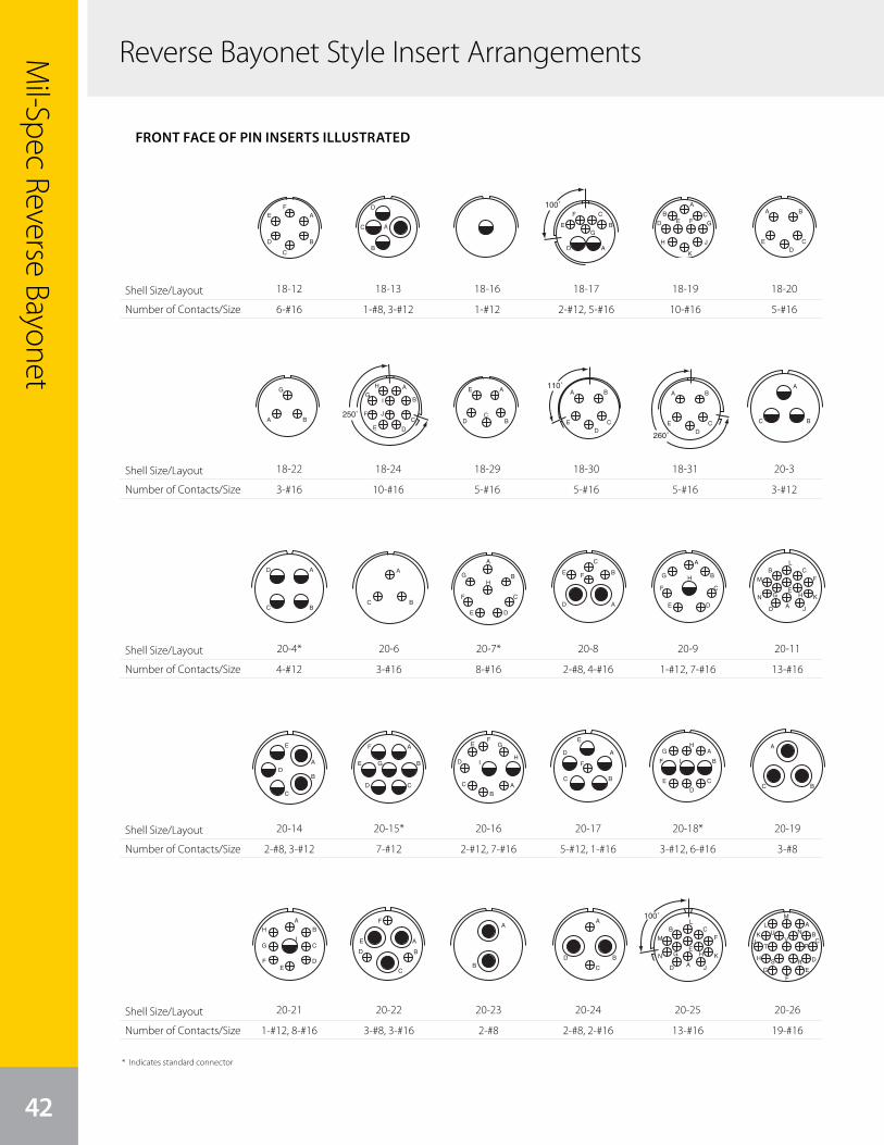
Mil-Spec Reverse Bayonet
42
Reverse Bayonet Style Insert Arrangements
Shell Size/Layout
Number of Contacts/Size
Shell Size/Layout
Number of Contacts/Size
Shell Size/Layout
Number of Contacts/Size
Shell Size/Layout
Number of Contacts/Size
Shell Size/Layout
Number of Contacts/Size
7
A
B
AB
AB
A
BC
DA
BC
A
B
CD
E
FG
H
A
B
C
D
E
F
G
A
BC
DA
BC
D
E
A
B
C
D
EF
A
B
C
D
A
B
A
B
C
D
100˚
A
B
C
D
E
F
G
A
B CD E F G
H
K
J
A B
CD
E
front face of pin insert or rear face of socket insert illustrated
GT Seriescontact arrangements
Insert Arrangement 16-10 16-11 16-12 16-13 16-59
Service Rating A A A A A
Number of Contacts 3 2 1 2* 4
Contact Size 12 12 4 12 12
Insert Arrangement 18-1 18-3 18-4 18-5 18-6 18-7
Service Rating B, C, F, G = A; Bal. = Inst. D D D D B
Number of Contacts 10 2 4 2 1 1 1
Contact Size 16 12 16 12 16 4 8
Insert Arrangement 18-8 18-9 18-10 18-11 18-12 18-13
Service Rating A Inst. A A A A
Number of Contacts 1 7 2 5 4 5 6 1 3
Contact Size 12 16 12 16 12 12 16 8 12
Insert Arrangement 18-14 18-15 18-16 18-17 18-19 18-20
Service Rating A A C Inst. A A
Number of Contacts 1 1 4** 1 2 5 10 5
Contact Size 4 16 12 12 12 16 16 16
CONTACT LEGEND 16 12 8 4 0
* A = Iron; B = Constantan**A, C = Iron; B, D = Constantan
100° Rotationof 18-9
A
B
C
DE
F
G
H
I
J
B
C AA B
C D
18-12
6-#16
8
110˚A B
CD
E
A
BC
A
BC
A
B
C
DE
F
GH
A
B
C
D
E F
A
B
C
DE
F
G H
A
B C
D
E
F
G H
J
K
L
M
N
A
B
A
B
C
D
E A
B
CD
E G
F
AB
C
D
EF
G
HI
A
BC
D
E
F
260˚
A B
CD
E
front face of pin insert or rear face of socket insert illustrated
GT Seriescontact arrangements
Insert Arrangement 18-22 18-24 18-29 18-30 18-31 20-2
Service Rating D B, C, F, G = A; Bal. = Inst. A A A D
Number of Contacts 3 10 5 5 5 1
Contact Size 16 16 16 16 16 0
Insert Arrangement 20-3 20-4 20-6 20-7 20-8 20-9
Service Rating D D D A, B, H, G = D; C, D, E, F = A Inst. H = D; Bal. = A
Number of Contacts 3 4 3 8 2 4 1 7
Contact Size 12 12 16 16 8 16 12 16
Insert Arrangement 20-11 20-12 20-14 20-15 20-16 20-17
Service Rating Inst. A A A A A
Number of Contacts 13 1 1 2 3 7 2 7 5 1
Contact Size 16 4 16 8 12 12 12 16 12 16
CONTACT LEGEND 16 12 8 4 0
110° Rotationof 18-20
A
BC
D
E
A
B
D
C
250˚
A
B
C
DE
F
G
H
I
JA B
G
250° Rotationof 18-1
260° Rotationof 18-2018-22
3-#16
8
110˚A B
CD
E
A
BC
A
BC
A
B
C
DE
F
GH
A
B
C
D
E F
A
B
C
DE
F
G H
A
B C
D
E
F
G H
J
K
L
M
N
A
B
A
B
C
D
E A
B
CD
E G
F
AB
C
D
EF
G
HI
A
BC
D
E
F
260˚
A B
CD
E
front face of pin insert or rear face of socket insert illustrated
GT Seriescontact arrangements
Insert Arrangement 18-22 18-24 18-29 18-30 18-31 20-2
Service Rating D B, C, F, G = A; Bal. = Inst. A A A D
Number of Contacts 3 10 5 5 5 1
Contact Size 16 16 16 16 16 0
Insert Arrangement 20-3 20-4 20-6 20-7 20-8 20-9
Service Rating D D D A, B, H, G = D; C, D, E, F = A Inst. H = D; Bal. = A
Number of Contacts 3 4 3 8 2 4 1 7
Contact Size 12 12 16 16 8 16 12 16
Insert Arrangement 20-11 20-12 20-14 20-15 20-16 20-17
Service Rating Inst. A A A A A
Number of Contacts 13 1 1 2 3 7 2 7 5 1
Contact Size 16 4 16 8 12 12 12 16 12 16
CONTACT LEGEND 16 12 8 4 0
110° Rotationof 18-20
A
BC
D
E
A
B
D
C
250˚
A
B
C
DE
F
G
H
I
JA B
G
250° Rotationof 18-1
260° Rotationof 18-20
20-4*
4-#12
8
110˚A B
CD
E
A
BC
A
BC
A
B
C
DE
F
GH
A
B
C
D
E F
A
B
C
DE
F
G H
A
B C
D
E
F
G H
J
K
L
M
N
A
B
A
B
C
D
E A
B
CD
E G
F
AB
C
D
EF
G
HI
A
BC
D
E
F
260˚
A B
CD
E
front face of pin insert or rear face of socket insert illustrated
GT Seriescontact arrangements
Insert Arrangement 18-22 18-24 18-29 18-30 18-31 20-2
Service Rating D B, C, F, G = A; Bal. = Inst. A A A D
Number of Contacts 3 10 5 5 5 1
Contact Size 16 16 16 16 16 0
Insert Arrangement 20-3 20-4 20-6 20-7 20-8 20-9
Service Rating D D D A, B, H, G = D; C, D, E, F = A Inst. H = D; Bal. = A
Number of Contacts 3 4 3 8 2 4 1 7
Contact Size 12 12 16 16 8 16 12 16
Insert Arrangement 20-11 20-12 20-14 20-15 20-16 20-17
Service Rating Inst. A A A A A
Number of Contacts 13 1 1 2 3 7 2 7 5 1
Contact Size 16 4 16 8 12 12 12 16 12 16
CONTACT LEGEND 16 12 8 4 0
110° Rotationof 18-20
A
BC
D
E
A
B
D
C
250˚
A
B
C
DE
F
G
H
I
JA B
G
250° Rotationof 18-1
260° Rotationof 18-20
20-14
2-#8, 3-#12
9
A
B
C
D
A
B
C
DE
F
G
H
I A
B
C
D
E
FA
B
A
B
C
D
100˚
A
B C
D
E
F
G H
J
K
L
M
N
AB
CD
EF
G
H
IJ
K
L
M
N
A BC
D
E
FGH
J
K
L
MN
PT
S R
250˚A
B C
D
E
F
G H
J
K
L
M
N
AB
C
D
EF
K
H
JM
L
front face of pin insert or rear face of socket insert illustrated
GT Seriescontact arrangements
Insert Arrangement 20-18 20-19 20-20 20-21 20-22 20-23
Service Rating A A A A A A
Number of Contacts 3 6 3 1 3 1 8 3 3 2
Contact Size 12 16 8 4 12 12 16 8 16 8
Insert Arrangement 20-24 20-25 20-26 20-27 20-29 20-30
Service Rating A Inst. A A A Inst.
Number of Contacts 2 2 13 19 14 17 13
Contact Size 8 16 16 16 16 16 16
Insert Arrangement 20-33 20-51 20-57 20-58 20-59 20-66
Service Rating A A A A A A
Number of Contacts 11 3* 7* 5 5 3* 1 5
Contact Size 16 8 12 for #14 or 16 wire 12 16 8 for #10 or 12 wire 16 12 for #10 wire
* Solderless CONTACT LEGEND 16 12 8 4 0
250° Rotationof 20-11
100° Rotationof 20-11
A
BC
A
B
C
D
E
F
GH
I
A
BC
D
EF
G
H S R
JT
VP
K
LM
U N
A
B
CA
B
CD
E G
FA
BC
D E
F
HJ
K
L
A
B
C A
BC
D
E
F
20-21
1-#12, 8-#16
7
A
B
AB
AB
A
BC
DA
BC
A
B
CD
E
FG
H
A
B
C
D
E
F
G
A
BC
DA
BC
D
E
A
B
C
D
EF
A
B
C
D
A
B
A
B
C
D
100˚
A
B
C
D
E
F
G
A
B CD E F G
H
K
J
A B
CD
E
front face of pin insert or rear face of socket insert illustrated
GT Seriescontact arrangements
Insert Arrangement 16-10 16-11 16-12 16-13 16-59
Service Rating A A A A A
Number of Contacts 3 2 1 2* 4
Contact Size 12 12 4 12 12
Insert Arrangement 18-1 18-3 18-4 18-5 18-6 18-7
Service Rating B, C, F, G = A; Bal. = Inst. D D D D B
Number of Contacts 10 2 4 2 1 1 1
Contact Size 16 12 16 12 16 4 8
Insert Arrangement 18-8 18-9 18-10 18-11 18-12 18-13
Service Rating A Inst. A A A A
Number of Contacts 1 7 2 5 4 5 6 1 3
Contact Size 12 16 12 16 12 12 16 8 12
Insert Arrangement 18-14 18-15 18-16 18-17 18-19 18-20
Service Rating A A C Inst. A A
Number of Contacts 1 1 4** 1 2 5 10 5
Contact Size 4 16 12 12 12 16 16 16
CONTACT LEGEND 16 12 8 4 0
* A = Iron; B = Constantan**A, C = Iron; B, D = Constantan
100° Rotationof 18-9
A
B
C
DE
F
G
H
I
J
B
C AA B
C D
18-13
1-#8, 3-#12
8
110˚A B
CD
E
A
BC
A
BC
A
B
C
DE
F
GH
A
B
C
D
E F
A
B
C
DE
F
G H
A
B C
D
E
F
G H
J
K
L
M
N
A
B
A
B
C
D
E A
B
CD
E G
F
AB
C
D
EF
G
HI
A
BC
D
E
F
260˚
A B
CD
E
front face of pin insert or rear face of socket insert illustrated
GT Seriescontact arrangements
Insert Arrangement 18-22 18-24 18-29 18-30 18-31 20-2
Service Rating D B, C, F, G = A; Bal. = Inst. A A A D
Number of Contacts 3 10 5 5 5 1
Contact Size 16 16 16 16 16 0
Insert Arrangement 20-3 20-4 20-6 20-7 20-8 20-9
Service Rating D D D A, B, H, G = D; C, D, E, F = A Inst. H = D; Bal. = A
Number of Contacts 3 4 3 8 2 4 1 7
Contact Size 12 12 16 16 8 16 12 16
Insert Arrangement 20-11 20-12 20-14 20-15 20-16 20-17
Service Rating Inst. A A A A A
Number of Contacts 13 1 1 2 3 7 2 7 5 1
Contact Size 16 4 16 8 12 12 12 16 12 16
CONTACT LEGEND 16 12 8 4 0
110° Rotationof 18-20
A
BC
D
E
A
B
D
C
250˚
A
B
C
DE
F
G
H
I
JA B
G
250° Rotationof 18-1
260° Rotationof 18-2018-24
10-#16
8
110˚A B
CD
E
A
BC
A
BC
A
B
C
DE
F
GH
A
B
C
D
E F
A
B
C
DE
F
G H
A
B C
D
E
F
G H
J
K
L
M
N
A
B
A
B
C
D
E A
B
CD
E G
F
AB
C
D
EF
G
HI
A
BC
D
E
F
260˚
A B
CD
E
front face of pin insert or rear face of socket insert illustrated
GT Seriescontact arrangements
Insert Arrangement 18-22 18-24 18-29 18-30 18-31 20-2
Service Rating D B, C, F, G = A; Bal. = Inst. A A A D
Number of Contacts 3 10 5 5 5 1
Contact Size 16 16 16 16 16 0
Insert Arrangement 20-3 20-4 20-6 20-7 20-8 20-9
Service Rating D D D A, B, H, G = D; C, D, E, F = A Inst. H = D; Bal. = A
Number of Contacts 3 4 3 8 2 4 1 7
Contact Size 12 12 16 16 8 16 12 16
Insert Arrangement 20-11 20-12 20-14 20-15 20-16 20-17
Service Rating Inst. A A A A A
Number of Contacts 13 1 1 2 3 7 2 7 5 1
Contact Size 16 4 16 8 12 12 12 16 12 16
CONTACT LEGEND 16 12 8 4 0
110° Rotationof 18-20
A
BC
D
E
A
B
D
C
250˚
A
B
C
DE
F
G
H
I
JA B
G
250° Rotationof 18-1
260° Rotationof 18-20
20-6
3-#16
8
110˚A B
CD
E
A
BC
A
BC
A
B
C
DE
F
GH
A
B
C
D
E F
A
B
C
DE
F
G H
A
B C
D
E
F
G H
J
K
L
M
N
A
B
A
B
C
D
E A
B
CD
E G
F
AB
C
D
EF
G
HI
A
BC
D
E
F
260˚
A B
CD
E
front face of pin insert or rear face of socket insert illustrated
GT Seriescontact arrangements
Insert Arrangement 18-22 18-24 18-29 18-30 18-31 20-2
Service Rating D B, C, F, G = A; Bal. = Inst. A A A D
Number of Contacts 3 10 5 5 5 1
Contact Size 16 16 16 16 16 0
Insert Arrangement 20-3 20-4 20-6 20-7 20-8 20-9
Service Rating D D D A, B, H, G = D; C, D, E, F = A Inst. H = D; Bal. = A
Number of Contacts 3 4 3 8 2 4 1 7
Contact Size 12 12 16 16 8 16 12 16
Insert Arrangement 20-11 20-12 20-14 20-15 20-16 20-17
Service Rating Inst. A A A A A
Number of Contacts 13 1 1 2 3 7 2 7 5 1
Contact Size 16 4 16 8 12 12 12 16 12 16
CONTACT LEGEND 16 12 8 4 0
110° Rotationof 18-20
A
BC
D
E
A
B
D
C
250˚
A
B
C
DE
F
G
H
I
JA B
G
250° Rotationof 18-1
260° Rotationof 18-20
20-15*
7-#12
9
A
B
C
D
A
B
C
DE
F
G
H
I A
B
C
D
E
FA
B
A
B
C
D
100˚
A
B C
D
E
F
G H
J
K
L
M
N
AB
CD
EF
G
H
IJ
K
L
M
N
A BC
D
E
FGH
J
K
L
MN
PT
S R
250˚A
B C
D
E
F
G H
J
K
L
M
N
AB
C
D
EF
K
H
JM
L
front face of pin insert or rear face of socket insert illustrated
GT Seriescontact arrangements
Insert Arrangement 20-18 20-19 20-20 20-21 20-22 20-23
Service Rating A A A A A A
Number of Contacts 3 6 3 1 3 1 8 3 3 2
Contact Size 12 16 8 4 12 12 16 8 16 8
Insert Arrangement 20-24 20-25 20-26 20-27 20-29 20-30
Service Rating A Inst. A A A Inst.
Number of Contacts 2 2 13 19 14 17 13
Contact Size 8 16 16 16 16 16 16
Insert Arrangement 20-33 20-51 20-57 20-58 20-59 20-66
Service Rating A A A A A A
Number of Contacts 11 3* 7* 5 5 3* 1 5
Contact Size 16 8 12 for #14 or 16 wire 12 16 8 for #10 or 12 wire 16 12 for #10 wire
* Solderless CONTACT LEGEND 16 12 8 4 0
250° Rotationof 20-11
100° Rotationof 20-11
A
BC
A
B
C
D
E
F
GH
I
A
BC
D
EF
G
H S R
JT
VP
K
LM
U N
A
B
CA
B
CD
E G
FA
BC
D E
F
HJ
K
L
A
B
C A
BC
D
E
F
20-22
3-#8, 3-#16
7
A
B
AB
AB
A
BC
DA
BC
A
B
CD
E
FG
H
A
B
C
D
E
F
G
A
BC
DA
BC
D
E
A
B
C
D
EF
A
B
C
D
A
B
A
B
C
D
100˚
A
B
C
D
E
F
G
A
B CD E F G
H
K
J
A B
CD
E
front face of pin insert or rear face of socket insert illustrated
GT Seriescontact arrangements
Insert Arrangement 16-10 16-11 16-12 16-13 16-59
Service Rating A A A A A
Number of Contacts 3 2 1 2* 4
Contact Size 12 12 4 12 12
Insert Arrangement 18-1 18-3 18-4 18-5 18-6 18-7
Service Rating B, C, F, G = A; Bal. = Inst. D D D D B
Number of Contacts 10 2 4 2 1 1 1
Contact Size 16 12 16 12 16 4 8
Insert Arrangement 18-8 18-9 18-10 18-11 18-12 18-13
Service Rating A Inst. A A A A
Number of Contacts 1 7 2 5 4 5 6 1 3
Contact Size 12 16 12 16 12 12 16 8 12
Insert Arrangement 18-14 18-15 18-16 18-17 18-19 18-20
Service Rating A A C Inst. A A
Number of Contacts 1 1 4** 1 2 5 10 5
Contact Size 4 16 12 12 12 16 16 16
CONTACT LEGEND 16 12 8 4 0
* A = Iron; B = Constantan**A, C = Iron; B, D = Constantan
100° Rotationof 18-9
A
B
C
DE
F
G
H
I
J
B
C AA B
C D
18-16
1-#12
8
110˚A B
CD
E
A
BC
A
BC
A
B
C
DE
F
GH
A
B
C
D
E F
A
B
C
DE
F
G H
A
B C
D
E
F
G H
J
K
L
M
N
A
B
A
B
C
D
E A
B
CD
E G
F
AB
C
D
EF
G
HI
A
BC
D
E
F
260˚
A B
CD
E
front face of pin insert or rear face of socket insert illustrated
GT Seriescontact arrangements
Insert Arrangement 18-22 18-24 18-29 18-30 18-31 20-2
Service Rating D B, C, F, G = A; Bal. = Inst. A A A D
Number of Contacts 3 10 5 5 5 1
Contact Size 16 16 16 16 16 0
Insert Arrangement 20-3 20-4 20-6 20-7 20-8 20-9
Service Rating D D D A, B, H, G = D; C, D, E, F = A Inst. H = D; Bal. = A
Number of Contacts 3 4 3 8 2 4 1 7
Contact Size 12 12 16 16 8 16 12 16
Insert Arrangement 20-11 20-12 20-14 20-15 20-16 20-17
Service Rating Inst. A A A A A
Number of Contacts 13 1 1 2 3 7 2 7 5 1
Contact Size 16 4 16 8 12 12 12 16 12 16
CONTACT LEGEND 16 12 8 4 0
110° Rotationof 18-20
A
BC
D
E
A
B
D
C
250˚
A
B
C
DE
F
G
H
I
JA B
G
250° Rotationof 18-1
260° Rotationof 18-2018-29
5-#16
8
110˚A B
CD
E
A
BC
A
BC
A
B
C
DE
F
GH
A
B
C
D
E F
A
B
C
DE
F
G H
A
B C
D
E
F
G H
J
K
L
M
N
A
B
A
B
C
D
E A
B
CD
E G
F
AB
C
D
EF
G
HI
A
BC
D
E
F
260˚
A B
CD
E
front face of pin insert or rear face of socket insert illustrated
GT Seriescontact arrangements
Insert Arrangement 18-22 18-24 18-29 18-30 18-31 20-2
Service Rating D B, C, F, G = A; Bal. = Inst. A A A D
Number of Contacts 3 10 5 5 5 1
Contact Size 16 16 16 16 16 0
Insert Arrangement 20-3 20-4 20-6 20-7 20-8 20-9
Service Rating D D D A, B, H, G = D; C, D, E, F = A Inst. H = D; Bal. = A
Number of Contacts 3 4 3 8 2 4 1 7
Contact Size 12 12 16 16 8 16 12 16
Insert Arrangement 20-11 20-12 20-14 20-15 20-16 20-17
Service Rating Inst. A A A A A
Number of Contacts 13 1 1 2 3 7 2 7 5 1
Contact Size 16 4 16 8 12 12 12 16 12 16
CONTACT LEGEND 16 12 8 4 0
110° Rotationof 18-20
A
BC
D
E
A
B
D
C
250˚
A
B
C
DE
F
G
H
I
JA B
G
250° Rotationof 18-1
260° Rotationof 18-20
20-7*
8-#16
8
110˚A B
CD
E
A
BC
A
BC
A
B
C
DE
F
GH
A
B
C
D
E F
A
B
C
DE
F
G H
A
B C
D
E
F
G H
J
K
L
M
N
A
B
A
B
C
D
E A
B
CD
E G
F
AB
C
D
EF
G
HI
A
BC
D
E
F
260˚
A B
CD
E
front face of pin insert or rear face of socket insert illustrated
GT Seriescontact arrangements
Insert Arrangement 18-22 18-24 18-29 18-30 18-31 20-2
Service Rating D B, C, F, G = A; Bal. = Inst. A A A D
Number of Contacts 3 10 5 5 5 1
Contact Size 16 16 16 16 16 0
Insert Arrangement 20-3 20-4 20-6 20-7 20-8 20-9
Service Rating D D D A, B, H, G = D; C, D, E, F = A Inst. H = D; Bal. = A
Number of Contacts 3 4 3 8 2 4 1 7
Contact Size 12 12 16 16 8 16 12 16
Insert Arrangement 20-11 20-12 20-14 20-15 20-16 20-17
Service Rating Inst. A A A A A
Number of Contacts 13 1 1 2 3 7 2 7 5 1
Contact Size 16 4 16 8 12 12 12 16 12 16
CONTACT LEGEND 16 12 8 4 0
110° Rotationof 18-20
A
BC
D
E
A
B
D
C
250˚
A
B
C
DE
F
G
H
I
JA B
G
250° Rotationof 18-1
260° Rotationof 18-20
20-16
2-#12, 7-#16
9
A
B
C
D
A
B
C
DE
F
G
H
I A
B
C
D
E
FA
B
A
B
C
D
100˚
A
B C
D
E
F
G H
J
K
L
M
N
AB
CD
EF
G
H
IJ
K
L
M
N
A BC
D
E
FGH
J
K
L
MN
PT
S R
250˚A
B C
D
E
F
G H
J
K
L
M
N
AB
C
D
EF
K
H
JM
L
front face of pin insert or rear face of socket insert illustrated
GT Seriescontact arrangements
Insert Arrangement 20-18 20-19 20-20 20-21 20-22 20-23
Service Rating A A A A A A
Number of Contacts 3 6 3 1 3 1 8 3 3 2
Contact Size 12 16 8 4 12 12 16 8 16 8
Insert Arrangement 20-24 20-25 20-26 20-27 20-29 20-30
Service Rating A Inst. A A A Inst.
Number of Contacts 2 2 13 19 14 17 13
Contact Size 8 16 16 16 16 16 16
Insert Arrangement 20-33 20-51 20-57 20-58 20-59 20-66
Service Rating A A A A A A
Number of Contacts 11 3* 7* 5 5 3* 1 5
Contact Size 16 8 12 for #14 or 16 wire 12 16 8 for #10 or 12 wire 16 12 for #10 wire
* Solderless CONTACT LEGEND 16 12 8 4 0
250° Rotationof 20-11
100° Rotationof 20-11
A
BC
A
B
C
D
E
F
GH
I
A
BC
D
EF
G
H S R
JT
VP
K
LM
U N
A
B
CA
B
CD
E G
FA
BC
D E
F
HJ
K
L
A
B
C A
BC
D
E
F
20-23
2-#8
7
A
B
AB
AB
A
BC
DA
BC
A
B
CD
E
FG
H
A
B
C
D
E
F
G
A
BC
DA
BC
D
E
A
B
C
D
EF
A
B
C
D
A
B
A
B
C
D
100˚
A
B
C
D
E
F
G
A
B CD E F G
H
K
J
A B
CD
E
front face of pin insert or rear face of socket insert illustrated
GT Seriescontact arrangements
Insert Arrangement 16-10 16-11 16-12 16-13 16-59
Service Rating A A A A A
Number of Contacts 3 2 1 2* 4
Contact Size 12 12 4 12 12
Insert Arrangement 18-1 18-3 18-4 18-5 18-6 18-7
Service Rating B, C, F, G = A; Bal. = Inst. D D D D B
Number of Contacts 10 2 4 2 1 1 1
Contact Size 16 12 16 12 16 4 8
Insert Arrangement 18-8 18-9 18-10 18-11 18-12 18-13
Service Rating A Inst. A A A A
Number of Contacts 1 7 2 5 4 5 6 1 3
Contact Size 12 16 12 16 12 12 16 8 12
Insert Arrangement 18-14 18-15 18-16 18-17 18-19 18-20
Service Rating A A C Inst. A A
Number of Contacts 1 1 4** 1 2 5 10 5
Contact Size 4 16 12 12 12 16 16 16
CONTACT LEGEND 16 12 8 4 0
* A = Iron; B = Constantan**A, C = Iron; B, D = Constantan
100° Rotationof 18-9
A
B
C
DE
F
G
H
I
J
B
C AA B
C D
18-17
2-#12, 5-#16
8
110˚A B
CD
E
A
BC
A
BC
A
B
C
DE
F
GH
A
B
C
D
E F
A
B
C
DE
F
G H
A
B C
D
E
F
G H
J
K
L
M
N
A
B
A
B
C
D
E A
B
CD
E G
F
AB
C
D
EF
G
HI
A
BC
D
E
F
260˚
A B
CD
E
front face of pin insert or rear face of socket insert illustrated
GT Seriescontact arrangements
Insert Arrangement 18-22 18-24 18-29 18-30 18-31 20-2
Service Rating D B, C, F, G = A; Bal. = Inst. A A A D
Number of Contacts 3 10 5 5 5 1
Contact Size 16 16 16 16 16 0
Insert Arrangement 20-3 20-4 20-6 20-7 20-8 20-9
Service Rating D D D A, B, H, G = D; C, D, E, F = A Inst. H = D; Bal. = A
Number of Contacts 3 4 3 8 2 4 1 7
Contact Size 12 12 16 16 8 16 12 16
Insert Arrangement 20-11 20-12 20-14 20-15 20-16 20-17
Service Rating Inst. A A A A A
Number of Contacts 13 1 1 2 3 7 2 7 5 1
Contact Size 16 4 16 8 12 12 12 16 12 16
CONTACT LEGEND 16 12 8 4 0
110° Rotationof 18-20
A
BC
D
E
A
B
D
C
250˚
A
B
C
DE
F
G
H
I
JA B
G
250° Rotationof 18-1
260° Rotationof 18-2018-30
5-#16
8
110˚A B
CD
E
A
BC
A
BC
A
B
C
DE
F
GH
A
B
C
D
E F
A
B
C
DE
F
G H
A
B C
D
E
F
G H
J
K
L
M
N
A
B
A
B
C
D
E A
B
CD
E G
F
AB
C
D
EF
G
HI
A
BC
D
E
F
260˚
A B
CD
E
front face of pin insert or rear face of socket insert illustrated
GT Seriescontact arrangements
Insert Arrangement 18-22 18-24 18-29 18-30 18-31 20-2
Service Rating D B, C, F, G = A; Bal. = Inst. A A A D
Number of Contacts 3 10 5 5 5 1
Contact Size 16 16 16 16 16 0
Insert Arrangement 20-3 20-4 20-6 20-7 20-8 20-9
Service Rating D D D A, B, H, G = D; C, D, E, F = A Inst. H = D; Bal. = A
Number of Contacts 3 4 3 8 2 4 1 7
Contact Size 12 12 16 16 8 16 12 16
Insert Arrangement 20-11 20-12 20-14 20-15 20-16 20-17
Service Rating Inst. A A A A A
Number of Contacts 13 1 1 2 3 7 2 7 5 1
Contact Size 16 4 16 8 12 12 12 16 12 16
CONTACT LEGEND 16 12 8 4 0
110° Rotationof 18-20
A
BC
D
E
A
B
D
C
250˚
A
B
C
DE
F
G
H
I
JA B
G
250° Rotationof 18-1
260° Rotationof 18-20
20-8
2-#8, 4-#16
8
110˚A B
CD
E
A
BC
A
BC
A
B
C
DE
F
GH
A
B
C
D
E F
A
B
C
DE
F
G H
A
B C
D
E
F
G H
J
K
L
M
N
A
B
A
B
C
D
E A
B
CD
E G
F
AB
C
D
EF
G
HI
A
BC
D
E
F
260˚
A B
CD
E
front face of pin insert or rear face of socket insert illustrated
GT Seriescontact arrangements
Insert Arrangement 18-22 18-24 18-29 18-30 18-31 20-2
Service Rating D B, C, F, G = A; Bal. = Inst. A A A D
Number of Contacts 3 10 5 5 5 1
Contact Size 16 16 16 16 16 0
Insert Arrangement 20-3 20-4 20-6 20-7 20-8 20-9
Service Rating D D D A, B, H, G = D; C, D, E, F = A Inst. H = D; Bal. = A
Number of Contacts 3 4 3 8 2 4 1 7
Contact Size 12 12 16 16 8 16 12 16
Insert Arrangement 20-11 20-12 20-14 20-15 20-16 20-17
Service Rating Inst. A A A A A
Number of Contacts 13 1 1 2 3 7 2 7 5 1
Contact Size 16 4 16 8 12 12 12 16 12 16
CONTACT LEGEND 16 12 8 4 0
110° Rotationof 18-20
A
BC
D
E
A
B
D
C
250˚
A
B
C
DE
F
G
H
I
JA B
G
250° Rotationof 18-1
260° Rotationof 18-20
20-17
5-#12, 1-#16
9
A
B
C
D
A
B
C
DE
F
G
H
I A
B
C
D
E
FA
B
A
B
C
D
100˚
A
B C
D
E
F
G H
J
K
L
M
N
AB
CD
EF
G
H
IJ
K
L
M
N
A BC
D
E
FGH
J
K
L
MN
PT
S R
250˚A
B C
D
E
F
G H
J
K
L
M
N
AB
C
D
EF
K
H
JM
L
front face of pin insert or rear face of socket insert illustrated
GT Seriescontact arrangements
Insert Arrangement 20-18 20-19 20-20 20-21 20-22 20-23
Service Rating A A A A A A
Number of Contacts 3 6 3 1 3 1 8 3 3 2
Contact Size 12 16 8 4 12 12 16 8 16 8
Insert Arrangement 20-24 20-25 20-26 20-27 20-29 20-30
Service Rating A Inst. A A A Inst.
Number of Contacts 2 2 13 19 14 17 13
Contact Size 8 16 16 16 16 16 16
Insert Arrangement 20-33 20-51 20-57 20-58 20-59 20-66
Service Rating A A A A A A
Number of Contacts 11 3* 7* 5 5 3* 1 5
Contact Size 16 8 12 for #14 or 16 wire 12 16 8 for #10 or 12 wire 16 12 for #10 wire
* Solderless CONTACT LEGEND 16 12 8 4 0
250° Rotationof 20-11
100° Rotationof 20-11
A
BC
A
B
C
D
E
F
GH
I
A
BC
D
EF
G
H S R
JT
VP
K
LM
U N
A
B
CA
B
CD
E G
FA
BC
D E
F
HJ
K
L
A
B
C A
BC
D
E
F
20-24
2-#8, 2-#16
7
A
B
AB
AB
A
BC
DA
BC
A
B
CD
E
FG
H
A
B
C
D
E
F
G
A
BC
DA
BC
D
E
A
B
C
D
EF
A
B
C
D
A
B
A
B
C
D
100˚
A
B
C
D
E
F
G
A
B CD E F G
H
K
J
A B
CD
E
front face of pin insert or rear face of socket insert illustrated
GT Seriescontact arrangements
Insert Arrangement 16-10 16-11 16-12 16-13 16-59
Service Rating A A A A A
Number of Contacts 3 2 1 2* 4
Contact Size 12 12 4 12 12
Insert Arrangement 18-1 18-3 18-4 18-5 18-6 18-7
Service Rating B, C, F, G = A; Bal. = Inst. D D D D B
Number of Contacts 10 2 4 2 1 1 1
Contact Size 16 12 16 12 16 4 8
Insert Arrangement 18-8 18-9 18-10 18-11 18-12 18-13
Service Rating A Inst. A A A A
Number of Contacts 1 7 2 5 4 5 6 1 3
Contact Size 12 16 12 16 12 12 16 8 12
Insert Arrangement 18-14 18-15 18-16 18-17 18-19 18-20
Service Rating A A C Inst. A A
Number of Contacts 1 1 4** 1 2 5 10 5
Contact Size 4 16 12 12 12 16 16 16
CONTACT LEGEND 16 12 8 4 0
* A = Iron; B = Constantan**A, C = Iron; B, D = Constantan
100° Rotationof 18-9
A
B
C
DE
F
G
H
I
J
B
C AA B
C D
18-19
10-#16
8
110˚A B
CD
E
A
BC
A
BC
A
B
C
DE
F
GH
A
B
C
D
E F
A
B
C
DE
F
G H
A
B C
D
E
F
G H
J
K
L
M
N
A
B
A
B
C
D
E A
B
CD
E G
F
AB
C
D
EF
G
HI
A
BC
D
E
F
260˚
A B
CD
E
front face of pin insert or rear face of socket insert illustrated
GT Seriescontact arrangements
Insert Arrangement 18-22 18-24 18-29 18-30 18-31 20-2
Service Rating D B, C, F, G = A; Bal. = Inst. A A A D
Number of Contacts 3 10 5 5 5 1
Contact Size 16 16 16 16 16 0
Insert Arrangement 20-3 20-4 20-6 20-7 20-8 20-9
Service Rating D D D A, B, H, G = D; C, D, E, F = A Inst. H = D; Bal. = A
Number of Contacts 3 4 3 8 2 4 1 7
Contact Size 12 12 16 16 8 16 12 16
Insert Arrangement 20-11 20-12 20-14 20-15 20-16 20-17
Service Rating Inst. A A A A A
Number of Contacts 13 1 1 2 3 7 2 7 5 1
Contact Size 16 4 16 8 12 12 12 16 12 16
CONTACT LEGEND 16 12 8 4 0
110° Rotationof 18-20
A
BC
D
E
A
B
D
C
250˚
A
B
C
DE
F
G
H
I
JA B
G
250° Rotationof 18-1
260° Rotationof 18-2018-31
5-#16
8
110˚A B
CD
E
A
BC
A
BC
A
B
C
DE
F
GH
A
B
C
D
E F
A
B
C
DE
F
G H
A
B C
D
E
F
G H
J
K
L
M
N
A
B
A
B
C
D
E A
B
CD
E G
F
AB
C
D
EF
G
HI
A
BC
D
E
F
260˚
A B
CD
E
front face of pin insert or rear face of socket insert illustrated
GT Seriescontact arrangements
Insert Arrangement 18-22 18-24 18-29 18-30 18-31 20-2
Service Rating D B, C, F, G = A; Bal. = Inst. A A A D
Number of Contacts 3 10 5 5 5 1
Contact Size 16 16 16 16 16 0
Insert Arrangement 20-3 20-4 20-6 20-7 20-8 20-9
Service Rating D D D A, B, H, G = D; C, D, E, F = A Inst. H = D; Bal. = A
Number of Contacts 3 4 3 8 2 4 1 7
Contact Size 12 12 16 16 8 16 12 16
Insert Arrangement 20-11 20-12 20-14 20-15 20-16 20-17
Service Rating Inst. A A A A A
Number of Contacts 13 1 1 2 3 7 2 7 5 1
Contact Size 16 4 16 8 12 12 12 16 12 16
CONTACT LEGEND 16 12 8 4 0
110° Rotationof 18-20
A
BC
D
E
A
B
D
C
250˚
A
B
C
DE
F
G
H
I
JA B
G
250° Rotationof 18-1
260° Rotationof 18-20
20-9
1-#12, 7-#16
9
A
B
C
D
A
B
C
DE
F
G
H
I A
B
C
D
E
FA
B
A
B
C
D
100˚
A
B C
D
E
F
G H
J
K
L
M
N
AB
CD
EF
G
H
IJ
K
L
M
N
A BC
D
E
FGH
J
K
L
MN
PT
S R
250˚A
B C
D
E
F
G H
J
K
L
M
N
AB
C
D
EF
K
H
JM
L
front face of pin insert or rear face of socket insert illustrated
GT Seriescontact arrangements
Insert Arrangement 20-18 20-19 20-20 20-21 20-22 20-23
Service Rating A A A A A A
Number of Contacts 3 6 3 1 3 1 8 3 3 2
Contact Size 12 16 8 4 12 12 16 8 16 8
Insert Arrangement 20-24 20-25 20-26 20-27 20-29 20-30
Service Rating A Inst. A A A Inst.
Number of Contacts 2 2 13 19 14 17 13
Contact Size 8 16 16 16 16 16 16
Insert Arrangement 20-33 20-51 20-57 20-58 20-59 20-66
Service Rating A A A A A A
Number of Contacts 11 3* 7* 5 5 3* 1 5
Contact Size 16 8 12 for #14 or 16 wire 12 16 8 for #10 or 12 wire 16 12 for #10 wire
* Solderless CONTACT LEGEND 16 12 8 4 0
250° Rotationof 20-11
100° Rotationof 20-11
A
BC
A
B
C
D
E
F
GH
I
A
BC
D
EF
G
H S R
JT
VP
K
LM
U N
A
B
CA
B
CD
E G
FA
BC
D E
F
HJ
K
L
A
B
C A
BC
D
E
F
20-18*
3-#12, 6-#16
9
A
B
C
D
A
B
C
DE
F
G
H
I A
B
C
D
E
FA
B
A
B
C
D
100˚
A
B C
D
E
F
G H
J
K
L
M
N
AB
CD
EF
G
H
IJ
K
L
M
N
A BC
D
E
FGH
J
K
L
MN
PT
S R
250˚A
B C
D
E
F
G H
J
K
L
M
N
AB
C
D
EF
K
H
JM
L
front face of pin insert or rear face of socket insert illustrated
GT Seriescontact arrangements
Insert Arrangement 20-18 20-19 20-20 20-21 20-22 20-23
Service Rating A A A A A A
Number of Contacts 3 6 3 1 3 1 8 3 3 2
Contact Size 12 16 8 4 12 12 16 8 16 8
Insert Arrangement 20-24 20-25 20-26 20-27 20-29 20-30
Service Rating A Inst. A A A Inst.
Number of Contacts 2 2 13 19 14 17 13
Contact Size 8 16 16 16 16 16 16
Insert Arrangement 20-33 20-51 20-57 20-58 20-59 20-66
Service Rating A A A A A A
Number of Contacts 11 3* 7* 5 5 3* 1 5
Contact Size 16 8 12 for #14 or 16 wire 12 16 8 for #10 or 12 wire 16 12 for #10 wire
* Solderless CONTACT LEGEND 16 12 8 4 0
250° Rotationof 20-11
100° Rotationof 20-11
A
BC
A
B
C
D
E
F
GH
I
A
BC
D
EF
G
H S R
JT
VP
K
LM
U N
A
B
CA
B
CD
E G
FA
BC
D E
F
HJ
K
L
A
B
C A
BC
D
E
F
20-25
13-#16
7
A
B
AB
AB
A
BC
DA
BC
A
B
CD
E
FG
H
A
B
C
D
E
F
G
A
BC
DA
BC
D
E
A
B
C
D
EF
A
B
C
D
A
B
A
B
C
D
100˚
A
B
C
D
E
F
G
A
B CD E F G
H
K
J
A B
CD
E
front face of pin insert or rear face of socket insert illustrated
GT Seriescontact arrangements
Insert Arrangement 16-10 16-11 16-12 16-13 16-59
Service Rating A A A A A
Number of Contacts 3 2 1 2* 4
Contact Size 12 12 4 12 12
Insert Arrangement 18-1 18-3 18-4 18-5 18-6 18-7
Service Rating B, C, F, G = A; Bal. = Inst. D D D D B
Number of Contacts 10 2 4 2 1 1 1
Contact Size 16 12 16 12 16 4 8
Insert Arrangement 18-8 18-9 18-10 18-11 18-12 18-13
Service Rating A Inst. A A A A
Number of Contacts 1 7 2 5 4 5 6 1 3
Contact Size 12 16 12 16 12 12 16 8 12
Insert Arrangement 18-14 18-15 18-16 18-17 18-19 18-20
Service Rating A A C Inst. A A
Number of Contacts 1 1 4** 1 2 5 10 5
Contact Size 4 16 12 12 12 16 16 16
CONTACT LEGEND 16 12 8 4 0
* A = Iron; B = Constantan**A, C = Iron; B, D = Constantan
100° Rotationof 18-9
A
B
C
DE
F
G
H
I
J
B
C AA B
C D
18-20
5-#16
8
110˚A B
CD
E
A
BC
A
BC
A
B
C
DE
F
GH
A
B
C
D
E F
A
B
C
DE
F
G H
A
B C
D
E
F
G H
J
K
L
M
N
A
B
A
B
C
D
E A
B
CD
E G
F
AB
C
D
EF
G
HI
A
BC
D
E
F
260˚
A B
CD
E
front face of pin insert or rear face of socket insert illustrated
GT Seriescontact arrangements
Insert Arrangement 18-22 18-24 18-29 18-30 18-31 20-2
Service Rating D B, C, F, G = A; Bal. = Inst. A A A D
Number of Contacts 3 10 5 5 5 1
Contact Size 16 16 16 16 16 0
Insert Arrangement 20-3 20-4 20-6 20-7 20-8 20-9
Service Rating D D D A, B, H, G = D; C, D, E, F = A Inst. H = D; Bal. = A
Number of Contacts 3 4 3 8 2 4 1 7
Contact Size 12 12 16 16 8 16 12 16
Insert Arrangement 20-11 20-12 20-14 20-15 20-16 20-17
Service Rating Inst. A A A A A
Number of Contacts 13 1 1 2 3 7 2 7 5 1
Contact Size 16 4 16 8 12 12 12 16 12 16
CONTACT LEGEND 16 12 8 4 0
110° Rotationof 18-20
A
BC
D
E
A
B
D
C
250˚
A
B
C
DE
F
G
H
I
JA B
G
250° Rotationof 18-1
260° Rotationof 18-20
20-3
3-#12
8
110˚A B
CD
E
A
BC
A
BC
A
B
C
DE
F
GH
A
B
C
D
E F
A
B
C
DE
F
G H
A
B C
D
E
F
G H
J
K
L
M
N
A
B
A
B
C
D
E A
B
CD
E G
F
AB
C
D
EF
G
HI
A
BC
D
E
F
260˚
A B
CD
E
front face of pin insert or rear face of socket insert illustrated
GT Seriescontact arrangements
Insert Arrangement 18-22 18-24 18-29 18-30 18-31 20-2
Service Rating D B, C, F, G = A; Bal. = Inst. A A A D
Number of Contacts 3 10 5 5 5 1
Contact Size 16 16 16 16 16 0
Insert Arrangement 20-3 20-4 20-6 20-7 20-8 20-9
Service Rating D D D A, B, H, G = D; C, D, E, F = A Inst. H = D; Bal. = A
Number of Contacts 3 4 3 8 2 4 1 7
Contact Size 12 12 16 16 8 16 12 16
Insert Arrangement 20-11 20-12 20-14 20-15 20-16 20-17
Service Rating Inst. A A A A A
Number of Contacts 13 1 1 2 3 7 2 7 5 1
Contact Size 16 4 16 8 12 12 12 16 12 16
CONTACT LEGEND 16 12 8 4 0
110° Rotationof 18-20
A
BC
D
E
A
B
D
C
250˚
A
B
C
DE
F
G
H
I
JA B
G
250° Rotationof 18-1
260° Rotationof 18-20
20-11
13-#16
9
A
B
C
D
A
B
C
DE
F
G
H
I A
B
C
D
E
FA
B
A
B
C
D
100˚
A
B C
D
E
F
G H
J
K
L
M
N
AB
CD
EF
G
H
IJ
K
L
M
N
A BC
D
E
FGH
J
K
L
MN
PT
S R
250˚A
B C
D
E
F
G H
J
K
L
M
N
AB
C
D
EF
K
H
JM
L
front face of pin insert or rear face of socket insert illustrated
GT Seriescontact arrangements
Insert Arrangement 20-18 20-19 20-20 20-21 20-22 20-23
Service Rating A A A A A A
Number of Contacts 3 6 3 1 3 1 8 3 3 2
Contact Size 12 16 8 4 12 12 16 8 16 8
Insert Arrangement 20-24 20-25 20-26 20-27 20-29 20-30
Service Rating A Inst. A A A Inst.
Number of Contacts 2 2 13 19 14 17 13
Contact Size 8 16 16 16 16 16 16
Insert Arrangement 20-33 20-51 20-57 20-58 20-59 20-66
Service Rating A A A A A A
Number of Contacts 11 3* 7* 5 5 3* 1 5
Contact Size 16 8 12 for #14 or 16 wire 12 16 8 for #10 or 12 wire 16 12 for #10 wire
* Solderless CONTACT LEGEND 16 12 8 4 0
250° Rotationof 20-11
100° Rotationof 20-11
A
BC
A
B
C
D
E
F
GH
I
A
BC
D
EF
G
H S R
JT
VP
K
LM
U N
A
B
CA
B
CD
E G
FA
BC
D E
F
HJ
K
L
A
B
C A
BC
D
E
F
20-19
3-#8
9
A
B
C
D
A
B
C
DE
F
G
H
I A
B
C
D
E
FA
B
A
B
C
D
100˚
A
B C
D
E
F
G H
J
K
L
M
N
AB
CD
EF
G
H
IJ
K
L
M
N
A BC
D
E
FGH
J
K
L
MN
PT
S R
250˚A
B C
D
E
F
G H
J
K
L
M
N
AB
C
D
EF
K
H
JM
L
front face of pin insert or rear face of socket insert illustrated
GT Seriescontact arrangements
Insert Arrangement 20-18 20-19 20-20 20-21 20-22 20-23
Service Rating A A A A A A
Number of Contacts 3 6 3 1 3 1 8 3 3 2
Contact Size 12 16 8 4 12 12 16 8 16 8
Insert Arrangement 20-24 20-25 20-26 20-27 20-29 20-30
Service Rating A Inst. A A A Inst.
Number of Contacts 2 2 13 19 14 17 13
Contact Size 8 16 16 16 16 16 16
Insert Arrangement 20-33 20-51 20-57 20-58 20-59 20-66
Service Rating A A A A A A
Number of Contacts 11 3* 7* 5 5 3* 1 5
Contact Size 16 8 12 for #14 or 16 wire 12 16 8 for #10 or 12 wire 16 12 for #10 wire
* Solderless CONTACT LEGEND 16 12 8 4 0
250° Rotationof 20-11
100° Rotationof 20-11
A
BC
A
B
C
D
E
F
GH
I
A
BC
D
EF
G
H S R
JT
VP
K
LM
U N
A
B
CA
B
CD
E G
FA
BC
D E
F
HJ
K
L
A
B
C A
BC
D
E
F
20-26
19-#16
* Indicates standard connector
FRONT FACE OF PIN INSERTS ILLUSTRATED
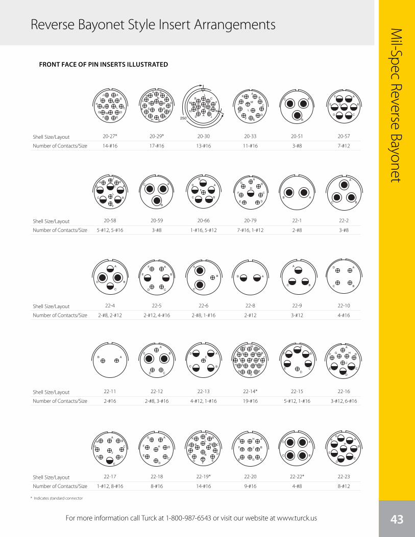
Mil-Spec Reverse Bayonet
Reverse Bayonet Style Insert Arrangements
43For more information call Turck at 1-800-987-6543 or visit our website at www.turck.us
Shell Size/Layout
Number of Contacts/Size
Shell Size/Layout
Number of Contacts/Size
Shell Size/Layout
Number of Contacts/Size
Shell Size/Layout
Number of Contacts/Size
Shell Size/Layout
Number of Contacts/Size
9
A
B
C
D
A
B
C
DE
F
G
H
I A
B
C
D
E
FA
B
A
B
C
D
100˚
A
B C
D
E
F
G H
J
K
L
M
N
AB
CD
EF
G
H
IJ
K
L
M
N
A BC
D
E
FGH
J
K
L
MN
PT
S R
250˚A
B C
D
E
F
G H
J
K
L
M
N
AB
C
D
EF
K
H
JM
L
front face of pin insert or rear face of socket insert illustrated
GT Seriescontact arrangements
Insert Arrangement 20-18 20-19 20-20 20-21 20-22 20-23
Service Rating A A A A A A
Number of Contacts 3 6 3 1 3 1 8 3 3 2
Contact Size 12 16 8 4 12 12 16 8 16 8
Insert Arrangement 20-24 20-25 20-26 20-27 20-29 20-30
Service Rating A Inst. A A A Inst.
Number of Contacts 2 2 13 19 14 17 13
Contact Size 8 16 16 16 16 16 16
Insert Arrangement 20-33 20-51 20-57 20-58 20-59 20-66
Service Rating A A A A A A
Number of Contacts 11 3* 7* 5 5 3* 1 5
Contact Size 16 8 12 for #14 or 16 wire 12 16 8 for #10 or 12 wire 16 12 for #10 wire
* Solderless CONTACT LEGEND 16 12 8 4 0
250° Rotationof 20-11
100° Rotationof 20-11
A
BC
A
B
C
D
E
F
GH
I
A
BC
D
EF
G
H S R
JT
VP
K
LM
U N
A
B
CA
B
CD
E G
FA
BC
D E
F
HJ
K
L
A
B
C A
BC
D
E
F
20-27*
14-#16
9
A
B
C
D
A
B
C
DE
F
G
H
I A
B
C
D
E
FA
B
A
B
C
D
100˚
A
B C
D
E
F
G H
J
K
L
M
N
AB
CD
EF
G
H
IJ
K
L
M
N
A BC
D
E
FGH
J
K
L
MN
PT
S R
250˚A
B C
D
E
F
G H
J
K
L
M
N
AB
C
D
EF
K
H
JM
L
front face of pin insert or rear face of socket insert illustrated
GT Seriescontact arrangements
Insert Arrangement 20-18 20-19 20-20 20-21 20-22 20-23
Service Rating A A A A A A
Number of Contacts 3 6 3 1 3 1 8 3 3 2
Contact Size 12 16 8 4 12 12 16 8 16 8
Insert Arrangement 20-24 20-25 20-26 20-27 20-29 20-30
Service Rating A Inst. A A A Inst.
Number of Contacts 2 2 13 19 14 17 13
Contact Size 8 16 16 16 16 16 16
Insert Arrangement 20-33 20-51 20-57 20-58 20-59 20-66
Service Rating A A A A A A
Number of Contacts 11 3* 7* 5 5 3* 1 5
Contact Size 16 8 12 for #14 or 16 wire 12 16 8 for #10 or 12 wire 16 12 for #10 wire
* Solderless CONTACT LEGEND 16 12 8 4 0
250° Rotationof 20-11
100° Rotationof 20-11
A
BC
A
B
C
D
E
F
GH
I
A
BC
D
EF
G
H S R
JT
VP
K
LM
U N
A
B
CA
B
CD
E G
FA
BC
D E
F
HJ
K
L
A
B
C A
BC
D
E
F
20-58
5-#12, 5-#16
10
A
BC
A
BC
D
AB
A
B
CD
E A
BC
DE
A
B
C
D
EF
G
H
J
K
L M
NU
V
RS
T P
A
B
E
F
CD
front face of pin insert or rear face of socket insert illustrated
GT Seriescontact arrangements
Insert Arrangement 20-79 22-1 22-2 22-4 22-5
Service Rating H=D; Bal. = A D D A D
Number of Contacts 7* 1* 2 3 2 2 2 4
Contact Size 16 12 for #16 wire 8 8 8 12 12 16
Insert Arrangement 22-6 22-7 22-8 22-9 22-10
Service Rating D E E E E
Number of Contacts 2 1 1 2 3 4
Contact Size 8 16 0 12 12 16
Insert Arrangement 22-11 22-12 22-13 22-14 22-15
Service Rating B D E = D; A, B, C, D = A A D = E; A, B, C, E, F = A
Number of Contacts 2 2 3 4 1 19 5 1
Contact Size 16 8 16 12 16 16 12 16
* Solderless CONTACT LEGEND 16 12 8 4 0
A
B
C
D
A
B
CD
E
F
A
B
C
AB
AB
A
BC
A
B
C
DE
F
G
H
22-4
2-#8, 2-#12
10
A
BC
A
BC
D
AB
A
B
CD
E A
BC
DE
A
B
C
D
EF
G
H
J
K
L M
NU
V
RS
T P
A
B
E
F
CD
front face of pin insert or rear face of socket insert illustrated
GT Seriescontact arrangements
Insert Arrangement 20-79 22-1 22-2 22-4 22-5
Service Rating H=D; Bal. = A D D A D
Number of Contacts 7* 1* 2 3 2 2 2 4
Contact Size 16 12 for #16 wire 8 8 8 12 12 16
Insert Arrangement 22-6 22-7 22-8 22-9 22-10
Service Rating D E E E E
Number of Contacts 2 1 1 2 3 4
Contact Size 8 16 0 12 12 16
Insert Arrangement 22-11 22-12 22-13 22-14 22-15
Service Rating B D E = D; A, B, C, D = A A D = E; A, B, C, E, F = A
Number of Contacts 2 2 3 4 1 19 5 1
Contact Size 16 8 16 12 16 16 12 16
* Solderless CONTACT LEGEND 16 12 8 4 0
A
B
C
D
A
B
CD
E
F
A
B
C
AB
AB
A
BC
A
B
C
DE
F
G
H
22-11
2-#16
11
A
B
C
D
E
F
AB
C
D
E
F
G
H
J
A
B
C
E
F
G
D
A
BCE
FG
D A
BC
DE
front face of pin insert or rear face of socket insert illustrated
GT Seriescontact arrangements
Insert Arrangement 22-16 22-17 22-18 22-19 22-20
Service Rating A A = D; Bal. = A A, B, F, G, H = D; C, D, E = A A A
Number of Contacts 3 6 1 8 8 14 9
Contact Size 12 16 12 16 16 16 16
Insert Arrangement 22-21 22-22 22-23 22-24 22-27
Service Rating A A H = D; Bal. = A C, D, E = D; A, B, F = A J = D; Bal. = A
Number of Contacts 1 2 4 8 2 4 1 8
Contact Size 0 16 8 12 12 16 8 16
Insert Arrangement 22-28 22-33 22-34 22-63 22-65
Service Rating A A, B, C, D = D; E. F. G = A D A H = D; Bal. = A
Number of Contacts 7 7 3 2 4 8 8*
Contact Size 12 16 12 16 12 16 12 for #14 or 16 wire
* Solderless CONTACT LEGEND 16 12 8 4 0
A
B
C
D
E
F G H
J
AB
C
D
E
F
G
H
J
A
B
C
D
E
F
G
H
AB
C
D
EF
G
H
J
KL
M
N
P
A
B
CDE
F
G H
J
A
B
C A
BC
DA
B
CD
E
FG
H
A
B C
EF
HJ
K
L
MN
D
A
B
CD
E
FG
H
22-17
1-#12, 8-#16
9
A
B
C
D
A
B
C
DE
F
G
H
I A
B
C
D
E
FA
B
A
B
C
D
100˚
A
B C
D
E
F
G H
J
K
L
M
N
AB
CD
EF
G
H
IJ
K
L
M
N
A BC
D
E
FGH
J
K
L
MN
PT
S R
250˚A
B C
D
E
F
G H
J
K
L
M
N
AB
C
D
EF
K
H
JM
L
front face of pin insert or rear face of socket insert illustrated
GT Seriescontact arrangements
Insert Arrangement 20-18 20-19 20-20 20-21 20-22 20-23
Service Rating A A A A A A
Number of Contacts 3 6 3 1 3 1 8 3 3 2
Contact Size 12 16 8 4 12 12 16 8 16 8
Insert Arrangement 20-24 20-25 20-26 20-27 20-29 20-30
Service Rating A Inst. A A A Inst.
Number of Contacts 2 2 13 19 14 17 13
Contact Size 8 16 16 16 16 16 16
Insert Arrangement 20-33 20-51 20-57 20-58 20-59 20-66
Service Rating A A A A A A
Number of Contacts 11 3* 7* 5 5 3* 1 5
Contact Size 16 8 12 for #14 or 16 wire 12 16 8 for #10 or 12 wire 16 12 for #10 wire
* Solderless CONTACT LEGEND 16 12 8 4 0
250° Rotationof 20-11
100° Rotationof 20-11
A
BC
A
B
C
D
E
F
GH
I
A
BC
D
EF
G
H S R
JT
VP
K
LM
U N
A
B
CA
B
CD
E G
FA
BC
D E
F
HJ
K
L
A
B
C A
BC
D
E
F
20-29*
17-#16
9
A
B
C
D
A
B
C
DE
F
G
H
I A
B
C
D
E
FA
B
A
B
C
D
100˚
A
B C
D
E
F
G H
J
K
L
M
N
AB
CD
EF
G
H
IJ
K
L
M
N
A BC
D
E
FGH
J
K
L
MN
PT
S R
250˚A
B C
D
E
F
G H
J
K
L
M
N
AB
C
D
EF
K
H
JM
L
front face of pin insert or rear face of socket insert illustrated
GT Seriescontact arrangements
Insert Arrangement 20-18 20-19 20-20 20-21 20-22 20-23
Service Rating A A A A A A
Number of Contacts 3 6 3 1 3 1 8 3 3 2
Contact Size 12 16 8 4 12 12 16 8 16 8
Insert Arrangement 20-24 20-25 20-26 20-27 20-29 20-30
Service Rating A Inst. A A A Inst.
Number of Contacts 2 2 13 19 14 17 13
Contact Size 8 16 16 16 16 16 16
Insert Arrangement 20-33 20-51 20-57 20-58 20-59 20-66
Service Rating A A A A A A
Number of Contacts 11 3* 7* 5 5 3* 1 5
Contact Size 16 8 12 for #14 or 16 wire 12 16 8 for #10 or 12 wire 16 12 for #10 wire
* Solderless CONTACT LEGEND 16 12 8 4 0
250° Rotationof 20-11
100° Rotationof 20-11
A
BC
A
B
C
D
E
F
GH
I
A
BC
D
EF
G
H S R
JT
VP
K
LM
U N
A
B
CA
B
CD
E G
FA
BC
D E
F
HJ
K
L
A
B
C A
BC
D
E
F
20-59
3-#8
10
A
BC
A
BC
D
AB
A
B
CD
E A
BC
DE
A
B
C
D
EF
G
H
J
K
L M
NU
V
RS
T P
A
B
E
F
CD
front face of pin insert or rear face of socket insert illustrated
GT Seriescontact arrangements
Insert Arrangement 20-79 22-1 22-2 22-4 22-5
Service Rating H=D; Bal. = A D D A D
Number of Contacts 7* 1* 2 3 2 2 2 4
Contact Size 16 12 for #16 wire 8 8 8 12 12 16
Insert Arrangement 22-6 22-7 22-8 22-9 22-10
Service Rating D E E E E
Number of Contacts 2 1 1 2 3 4
Contact Size 8 16 0 12 12 16
Insert Arrangement 22-11 22-12 22-13 22-14 22-15
Service Rating B D E = D; A, B, C, D = A A D = E; A, B, C, E, F = A
Number of Contacts 2 2 3 4 1 19 5 1
Contact Size 16 8 16 12 16 16 12 16
* Solderless CONTACT LEGEND 16 12 8 4 0
A
B
C
D
A
B
CD
E
F
A
B
C
AB
AB
A
BC
A
B
C
DE
F
G
H
22-5
2-#12, 4-#16
10
A
BC
A
BC
D
AB
A
B
CD
E A
BC
DE
A
B
C
D
EF
G
H
J
K
L M
NU
V
RS
T P
A
B
E
F
CD
front face of pin insert or rear face of socket insert illustrated
GT Seriescontact arrangements
Insert Arrangement 20-79 22-1 22-2 22-4 22-5
Service Rating H=D; Bal. = A D D A D
Number of Contacts 7* 1* 2 3 2 2 2 4
Contact Size 16 12 for #16 wire 8 8 8 12 12 16
Insert Arrangement 22-6 22-7 22-8 22-9 22-10
Service Rating D E E E E
Number of Contacts 2 1 1 2 3 4
Contact Size 8 16 0 12 12 16
Insert Arrangement 22-11 22-12 22-13 22-14 22-15
Service Rating B D E = D; A, B, C, D = A A D = E; A, B, C, E, F = A
Number of Contacts 2 2 3 4 1 19 5 1
Contact Size 16 8 16 12 16 16 12 16
* Solderless CONTACT LEGEND 16 12 8 4 0
A
B
C
D
A
B
CD
E
F
A
B
C
AB
AB
A
BC
A
B
C
DE
F
G
H
22-12
2-#8, 3-#16
11
A
B
C
D
E
F
AB
C
D
E
F
G
H
J
A
B
C
E
F
G
D
A
BCE
FG
D A
BC
DE
front face of pin insert or rear face of socket insert illustrated
GT Seriescontact arrangements
Insert Arrangement 22-16 22-17 22-18 22-19 22-20
Service Rating A A = D; Bal. = A A, B, F, G, H = D; C, D, E = A A A
Number of Contacts 3 6 1 8 8 14 9
Contact Size 12 16 12 16 16 16 16
Insert Arrangement 22-21 22-22 22-23 22-24 22-27
Service Rating A A H = D; Bal. = A C, D, E = D; A, B, F = A J = D; Bal. = A
Number of Contacts 1 2 4 8 2 4 1 8
Contact Size 0 16 8 12 12 16 8 16
Insert Arrangement 22-28 22-33 22-34 22-63 22-65
Service Rating A A, B, C, D = D; E. F. G = A D A H = D; Bal. = A
Number of Contacts 7 7 3 2 4 8 8*
Contact Size 12 16 12 16 12 16 12 for #14 or 16 wire
* Solderless CONTACT LEGEND 16 12 8 4 0
A
B
C
D
E
F G H
J
AB
C
D
E
F
G
H
J
A
B
C
D
E
F
G
H
AB
C
D
EF
G
H
J
KL
M
N
P
A
B
CDE
F
G H
J
A
B
C A
BC
DA
B
CD
E
FG
H
A
B C
EF
HJ
K
L
MN
D
A
B
CD
E
FG
H
22-18
8-#16
9
A
B
C
D
A
B
C
DE
F
G
H
I A
B
C
D
E
FA
B
A
B
C
D
100˚
A
B C
D
E
F
G H
J
K
L
M
N
AB
CD
EF
G
H
IJ
K
L
M
N
A BC
D
E
FGH
J
K
L
MN
PT
S R
250˚A
B C
D
E
F
G H
J
K
L
M
N
AB
C
D
EF
K
H
JM
L
front face of pin insert or rear face of socket insert illustrated
GT Seriescontact arrangements
Insert Arrangement 20-18 20-19 20-20 20-21 20-22 20-23
Service Rating A A A A A A
Number of Contacts 3 6 3 1 3 1 8 3 3 2
Contact Size 12 16 8 4 12 12 16 8 16 8
Insert Arrangement 20-24 20-25 20-26 20-27 20-29 20-30
Service Rating A Inst. A A A Inst.
Number of Contacts 2 2 13 19 14 17 13
Contact Size 8 16 16 16 16 16 16
Insert Arrangement 20-33 20-51 20-57 20-58 20-59 20-66
Service Rating A A A A A A
Number of Contacts 11 3* 7* 5 5 3* 1 5
Contact Size 16 8 12 for #14 or 16 wire 12 16 8 for #10 or 12 wire 16 12 for #10 wire
* Solderless CONTACT LEGEND 16 12 8 4 0
250° Rotationof 20-11
100° Rotationof 20-11
A
BC
A
B
C
D
E
F
GH
I
A
BC
D
EF
G
H S R
JT
VP
K
LM
U N
A
B
CA
B
CD
E G
FA
BC
D E
F
HJ
K
L
A
B
C A
BC
D
E
F
20-30
13-#16
9
A
B
C
D
A
B
C
DE
F
G
H
I A
B
C
D
E
FA
B
A
B
C
D
100˚
A
B C
D
E
F
G H
J
K
L
M
N
AB
CD
EF
G
H
IJ
K
L
M
N
A BC
D
E
FGH
J
K
L
MN
PT
S R
250˚A
B C
D
E
F
G H
J
K
L
M
N
AB
C
D
EF
K
H
JM
L
front face of pin insert or rear face of socket insert illustrated
GT Seriescontact arrangements
Insert Arrangement 20-18 20-19 20-20 20-21 20-22 20-23
Service Rating A A A A A A
Number of Contacts 3 6 3 1 3 1 8 3 3 2
Contact Size 12 16 8 4 12 12 16 8 16 8
Insert Arrangement 20-24 20-25 20-26 20-27 20-29 20-30
Service Rating A Inst. A A A Inst.
Number of Contacts 2 2 13 19 14 17 13
Contact Size 8 16 16 16 16 16 16
Insert Arrangement 20-33 20-51 20-57 20-58 20-59 20-66
Service Rating A A A A A A
Number of Contacts 11 3* 7* 5 5 3* 1 5
Contact Size 16 8 12 for #14 or 16 wire 12 16 8 for #10 or 12 wire 16 12 for #10 wire
* Solderless CONTACT LEGEND 16 12 8 4 0
250° Rotationof 20-11
100° Rotationof 20-11
A
BC
A
B
C
D
E
F
GH
I
A
BC
D
EF
G
H S R
JT
VP
K
LM
U N
A
B
CA
B
CD
E G
FA
BC
D E
F
HJ
K
L
A
B
C A
BC
D
E
F
20-66
1-#16, 5-#12
10
A
BC
A
BC
D
AB
A
B
CD
E A
BC
DE
A
B
C
D
EF
G
H
J
K
L M
NU
V
RS
T P
A
B
E
F
CD
front face of pin insert or rear face of socket insert illustrated
GT Seriescontact arrangements
Insert Arrangement 20-79 22-1 22-2 22-4 22-5
Service Rating H=D; Bal. = A D D A D
Number of Contacts 7* 1* 2 3 2 2 2 4
Contact Size 16 12 for #16 wire 8 8 8 12 12 16
Insert Arrangement 22-6 22-7 22-8 22-9 22-10
Service Rating D E E E E
Number of Contacts 2 1 1 2 3 4
Contact Size 8 16 0 12 12 16
Insert Arrangement 22-11 22-12 22-13 22-14 22-15
Service Rating B D E = D; A, B, C, D = A A D = E; A, B, C, E, F = A
Number of Contacts 2 2 3 4 1 19 5 1
Contact Size 16 8 16 12 16 16 12 16
* Solderless CONTACT LEGEND 16 12 8 4 0
A
B
C
D
A
B
CD
E
F
A
B
C
AB
AB
A
BC
A
B
C
DE
F
G
H
22-6
2-#8, 1-#16
10
A
BC
A
BC
D
AB
A
B
CD
E A
BC
DE
A
B
C
D
EF
G
H
J
K
L M
NU
V
RS
T P
A
B
E
F
CD
front face of pin insert or rear face of socket insert illustrated
GT Seriescontact arrangements
Insert Arrangement 20-79 22-1 22-2 22-4 22-5
Service Rating H=D; Bal. = A D D A D
Number of Contacts 7* 1* 2 3 2 2 2 4
Contact Size 16 12 for #16 wire 8 8 8 12 12 16
Insert Arrangement 22-6 22-7 22-8 22-9 22-10
Service Rating D E E E E
Number of Contacts 2 1 1 2 3 4
Contact Size 8 16 0 12 12 16
Insert Arrangement 22-11 22-12 22-13 22-14 22-15
Service Rating B D E = D; A, B, C, D = A A D = E; A, B, C, E, F = A
Number of Contacts 2 2 3 4 1 19 5 1
Contact Size 16 8 16 12 16 16 12 16
* Solderless CONTACT LEGEND 16 12 8 4 0
A
B
C
D
A
B
CD
E
F
A
B
C
AB
AB
A
BC
A
B
C
DE
F
G
H
22-13
4-#12, 1-#16
11
A
B
C
D
E
F
AB
C
D
E
F
G
H
J
A
B
C
E
F
G
D
A
BCE
FG
D A
BC
DE
front face of pin insert or rear face of socket insert illustrated
GT Seriescontact arrangements
Insert Arrangement 22-16 22-17 22-18 22-19 22-20
Service Rating A A = D; Bal. = A A, B, F, G, H = D; C, D, E = A A A
Number of Contacts 3 6 1 8 8 14 9
Contact Size 12 16 12 16 16 16 16
Insert Arrangement 22-21 22-22 22-23 22-24 22-27
Service Rating A A H = D; Bal. = A C, D, E = D; A, B, F = A J = D; Bal. = A
Number of Contacts 1 2 4 8 2 4 1 8
Contact Size 0 16 8 12 12 16 8 16
Insert Arrangement 22-28 22-33 22-34 22-63 22-65
Service Rating A A, B, C, D = D; E. F. G = A D A H = D; Bal. = A
Number of Contacts 7 7 3 2 4 8 8*
Contact Size 12 16 12 16 12 16 12 for #14 or 16 wire
* Solderless CONTACT LEGEND 16 12 8 4 0
A
B
C
D
E
F G H
J
AB
C
D
E
F
G
H
J
A
B
C
D
E
F
G
H
AB
C
D
EF
G
H
J
KL
M
N
P
A
B
CDE
F
G H
J
A
B
C A
BC
DA
B
CD
E
FG
H
A
B C
EF
HJ
K
L
MN
D
A
B
CD
E
FG
H
22-19*
14-#16
9
A
B
C
D
A
B
C
DE
F
G
H
I A
B
C
D
E
FA
B
A
B
C
D
100˚
A
B C
D
E
F
G H
J
K
L
M
N
AB
CD
EF
G
H
IJ
K
L
M
N
A BC
D
E
FGH
J
K
L
MN
PT
S R
250˚A
B C
D
E
F
G H
J
K
L
M
N
AB
C
D
EF
K
H
JM
L
front face of pin insert or rear face of socket insert illustrated
GT Seriescontact arrangements
Insert Arrangement 20-18 20-19 20-20 20-21 20-22 20-23
Service Rating A A A A A A
Number of Contacts 3 6 3 1 3 1 8 3 3 2
Contact Size 12 16 8 4 12 12 16 8 16 8
Insert Arrangement 20-24 20-25 20-26 20-27 20-29 20-30
Service Rating A Inst. A A A Inst.
Number of Contacts 2 2 13 19 14 17 13
Contact Size 8 16 16 16 16 16 16
Insert Arrangement 20-33 20-51 20-57 20-58 20-59 20-66
Service Rating A A A A A A
Number of Contacts 11 3* 7* 5 5 3* 1 5
Contact Size 16 8 12 for #14 or 16 wire 12 16 8 for #10 or 12 wire 16 12 for #10 wire
* Solderless CONTACT LEGEND 16 12 8 4 0
250° Rotationof 20-11
100° Rotationof 20-11
A
BC
A
B
C
D
E
F
GH
I
A
BC
D
EF
G
H S R
JT
VP
K
LM
U N
A
B
CA
B
CD
E G
FA
BC
D E
F
HJ
K
L
A
B
C A
BC
D
E
F
20-33
11-#16
10
A
BC
A
BC
D
AB
A
B
CD
E A
BC
DE
A
B
C
D
EF
G
H
J
K
L M
NU
V
RS
T P
A
B
E
F
CD
front face of pin insert or rear face of socket insert illustrated
GT Seriescontact arrangements
Insert Arrangement 20-79 22-1 22-2 22-4 22-5
Service Rating H=D; Bal. = A D D A D
Number of Contacts 7* 1* 2 3 2 2 2 4
Contact Size 16 12 for #16 wire 8 8 8 12 12 16
Insert Arrangement 22-6 22-7 22-8 22-9 22-10
Service Rating D E E E E
Number of Contacts 2 1 1 2 3 4
Contact Size 8 16 0 12 12 16
Insert Arrangement 22-11 22-12 22-13 22-14 22-15
Service Rating B D E = D; A, B, C, D = A A D = E; A, B, C, E, F = A
Number of Contacts 2 2 3 4 1 19 5 1
Contact Size 16 8 16 12 16 16 12 16
* Solderless CONTACT LEGEND 16 12 8 4 0
A
B
C
D
A
B
CD
E
F
A
B
C
AB
AB
A
BC
A
B
C
DE
F
G
H
20-79
7-#16, 1-#12
10
A
BC
A
BC
D
AB
A
B
CD
E A
BC
DE
A
B
C
D
EF
G
H
J
K
L M
NU
V
RS
T P
A
B
E
F
CD
front face of pin insert or rear face of socket insert illustrated
GT Seriescontact arrangements
Insert Arrangement 20-79 22-1 22-2 22-4 22-5
Service Rating H=D; Bal. = A D D A D
Number of Contacts 7* 1* 2 3 2 2 2 4
Contact Size 16 12 for #16 wire 8 8 8 12 12 16
Insert Arrangement 22-6 22-7 22-8 22-9 22-10
Service Rating D E E E E
Number of Contacts 2 1 1 2 3 4
Contact Size 8 16 0 12 12 16
Insert Arrangement 22-11 22-12 22-13 22-14 22-15
Service Rating B D E = D; A, B, C, D = A A D = E; A, B, C, E, F = A
Number of Contacts 2 2 3 4 1 19 5 1
Contact Size 16 8 16 12 16 16 12 16
* Solderless CONTACT LEGEND 16 12 8 4 0
A
B
C
D
A
B
CD
E
F
A
B
C
AB
AB
A
BC
A
B
C
DE
F
G
H
22-8
2-#12
10
A
BC
A
BC
D
AB
A
B
CD
E A
BC
DE
A
B
C
D
EF
G
H
J
K
L M
NU
V
RS
T P
A
B
E
F
CD
front face of pin insert or rear face of socket insert illustrated
GT Seriescontact arrangements
Insert Arrangement 20-79 22-1 22-2 22-4 22-5
Service Rating H=D; Bal. = A D D A D
Number of Contacts 7* 1* 2 3 2 2 2 4
Contact Size 16 12 for #16 wire 8 8 8 12 12 16
Insert Arrangement 22-6 22-7 22-8 22-9 22-10
Service Rating D E E E E
Number of Contacts 2 1 1 2 3 4
Contact Size 8 16 0 12 12 16
Insert Arrangement 22-11 22-12 22-13 22-14 22-15
Service Rating B D E = D; A, B, C, D = A A D = E; A, B, C, E, F = A
Number of Contacts 2 2 3 4 1 19 5 1
Contact Size 16 8 16 12 16 16 12 16
* Solderless CONTACT LEGEND 16 12 8 4 0
A
B
C
D
A
B
CD
E
F
A
B
C
AB
AB
A
BC
A
B
C
DE
F
G
H
22-14*
19-#16
11
A
B
C
D
E
F
AB
C
D
E
F
G
H
J
A
B
C
E
F
G
D
A
BCE
FG
D A
BC
DE
front face of pin insert or rear face of socket insert illustrated
GT Seriescontact arrangements
Insert Arrangement 22-16 22-17 22-18 22-19 22-20
Service Rating A A = D; Bal. = A A, B, F, G, H = D; C, D, E = A A A
Number of Contacts 3 6 1 8 8 14 9
Contact Size 12 16 12 16 16 16 16
Insert Arrangement 22-21 22-22 22-23 22-24 22-27
Service Rating A A H = D; Bal. = A C, D, E = D; A, B, F = A J = D; Bal. = A
Number of Contacts 1 2 4 8 2 4 1 8
Contact Size 0 16 8 12 12 16 8 16
Insert Arrangement 22-28 22-33 22-34 22-63 22-65
Service Rating A A, B, C, D = D; E. F. G = A D A H = D; Bal. = A
Number of Contacts 7 7 3 2 4 8 8*
Contact Size 12 16 12 16 12 16 12 for #14 or 16 wire
* Solderless CONTACT LEGEND 16 12 8 4 0
A
B
C
D
E
F G H
J
AB
C
D
E
F
G
H
J
A
B
C
D
E
F
G
H
AB
C
D
EF
G
H
J
KL
M
N
P
A
B
CDE
F
G H
J
A
B
C A
BC
DA
B
CD
E
FG
H
A
B C
EF
HJ
K
L
MN
D
A
B
CD
E
FG
H
22-20
9-#16
9
A
B
C
D
A
B
C
DE
F
G
H
I A
B
C
D
E
FA
B
A
B
C
D
100˚
A
B C
D
E
F
G H
J
K
L
M
N
AB
CD
EF
G
H
IJ
K
L
M
N
A BC
D
E
FGH
J
K
L
MN
PT
S R
250˚A
B C
D
E
F
G H
J
K
L
M
N
AB
C
D
EF
K
H
JM
L
front face of pin insert or rear face of socket insert illustrated
GT Seriescontact arrangements
Insert Arrangement 20-18 20-19 20-20 20-21 20-22 20-23
Service Rating A A A A A A
Number of Contacts 3 6 3 1 3 1 8 3 3 2
Contact Size 12 16 8 4 12 12 16 8 16 8
Insert Arrangement 20-24 20-25 20-26 20-27 20-29 20-30
Service Rating A Inst. A A A Inst.
Number of Contacts 2 2 13 19 14 17 13
Contact Size 8 16 16 16 16 16 16
Insert Arrangement 20-33 20-51 20-57 20-58 20-59 20-66
Service Rating A A A A A A
Number of Contacts 11 3* 7* 5 5 3* 1 5
Contact Size 16 8 12 for #14 or 16 wire 12 16 8 for #10 or 12 wire 16 12 for #10 wire
* Solderless CONTACT LEGEND 16 12 8 4 0
250° Rotationof 20-11
100° Rotationof 20-11
A
BC
A
B
C
D
E
F
GH
I
A
BC
D
EF
G
H S R
JT
VP
K
LM
U N
A
B
CA
B
CD
E G
FA
BC
D E
F
HJ
K
L
A
B
C A
BC
D
E
F
20-51
3-#8
10
A
BC
A
BC
D
AB
A
B
CD
E A
BC
DE
A
B
C
D
EF
G
H
J
K
L M
NU
V
RS
T P
A
B
E
F
CD
front face of pin insert or rear face of socket insert illustrated
GT Seriescontact arrangements
Insert Arrangement 20-79 22-1 22-2 22-4 22-5
Service Rating H=D; Bal. = A D D A D
Number of Contacts 7* 1* 2 3 2 2 2 4
Contact Size 16 12 for #16 wire 8 8 8 12 12 16
Insert Arrangement 22-6 22-7 22-8 22-9 22-10
Service Rating D E E E E
Number of Contacts 2 1 1 2 3 4
Contact Size 8 16 0 12 12 16
Insert Arrangement 22-11 22-12 22-13 22-14 22-15
Service Rating B D E = D; A, B, C, D = A A D = E; A, B, C, E, F = A
Number of Contacts 2 2 3 4 1 19 5 1
Contact Size 16 8 16 12 16 16 12 16
* Solderless CONTACT LEGEND 16 12 8 4 0
A
B
C
D
A
B
CD
E
F
A
B
C
AB
AB
A
BC
A
B
C
DE
F
G
H
22-1
2-#8
10
A
BC
A
BC
D
AB
A
B
CD
E A
BC
DE
A
B
C
D
EF
G
H
J
K
L M
NU
V
RS
T P
A
B
E
F
CD
front face of pin insert or rear face of socket insert illustrated
GT Seriescontact arrangements
Insert Arrangement 20-79 22-1 22-2 22-4 22-5
Service Rating H=D; Bal. = A D D A D
Number of Contacts 7* 1* 2 3 2 2 2 4
Contact Size 16 12 for #16 wire 8 8 8 12 12 16
Insert Arrangement 22-6 22-7 22-8 22-9 22-10
Service Rating D E E E E
Number of Contacts 2 1 1 2 3 4
Contact Size 8 16 0 12 12 16
Insert Arrangement 22-11 22-12 22-13 22-14 22-15
Service Rating B D E = D; A, B, C, D = A A D = E; A, B, C, E, F = A
Number of Contacts 2 2 3 4 1 19 5 1
Contact Size 16 8 16 12 16 16 12 16
* Solderless CONTACT LEGEND 16 12 8 4 0
A
B
C
D
A
B
CD
E
F
A
B
C
AB
AB
A
BC
A
B
C
DE
F
G
H
22-9
3-#12
10
A
BC
A
BC
D
AB
A
B
CD
E A
BC
DE
A
B
C
D
EF
G
H
J
K
L M
NU
V
RS
T P
A
B
E
F
CD
front face of pin insert or rear face of socket insert illustrated
GT Seriescontact arrangements
Insert Arrangement 20-79 22-1 22-2 22-4 22-5
Service Rating H=D; Bal. = A D D A D
Number of Contacts 7* 1* 2 3 2 2 2 4
Contact Size 16 12 for #16 wire 8 8 8 12 12 16
Insert Arrangement 22-6 22-7 22-8 22-9 22-10
Service Rating D E E E E
Number of Contacts 2 1 1 2 3 4
Contact Size 8 16 0 12 12 16
Insert Arrangement 22-11 22-12 22-13 22-14 22-15
Service Rating B D E = D; A, B, C, D = A A D = E; A, B, C, E, F = A
Number of Contacts 2 2 3 4 1 19 5 1
Contact Size 16 8 16 12 16 16 12 16
* Solderless CONTACT LEGEND 16 12 8 4 0
A
B
C
D
A
B
CD
E
F
A
B
C
AB
AB
A
BC
A
B
C
DE
F
G
H
22-15
5-#12, 1-#16
11
A
B
C
D
E
F
AB
C
D
E
F
G
H
J
A
B
C
E
F
G
D
A
BCE
FG
D A
BC
DE
front face of pin insert or rear face of socket insert illustrated
GT Seriescontact arrangements
Insert Arrangement 22-16 22-17 22-18 22-19 22-20
Service Rating A A = D; Bal. = A A, B, F, G, H = D; C, D, E = A A A
Number of Contacts 3 6 1 8 8 14 9
Contact Size 12 16 12 16 16 16 16
Insert Arrangement 22-21 22-22 22-23 22-24 22-27
Service Rating A A H = D; Bal. = A C, D, E = D; A, B, F = A J = D; Bal. = A
Number of Contacts 1 2 4 8 2 4 1 8
Contact Size 0 16 8 12 12 16 8 16
Insert Arrangement 22-28 22-33 22-34 22-63 22-65
Service Rating A A, B, C, D = D; E. F. G = A D A H = D; Bal. = A
Number of Contacts 7 7 3 2 4 8 8*
Contact Size 12 16 12 16 12 16 12 for #14 or 16 wire
* Solderless CONTACT LEGEND 16 12 8 4 0
A
B
C
D
E
F G H
J
AB
C
D
E
F
G
H
J
A
B
C
D
E
F
G
H
AB
C
D
EF
G
H
J
KL
M
N
P
A
B
CDE
F
G H
J
A
B
C A
BC
DA
B
CD
E
FG
H
A
B C
EF
HJ
K
L
MN
D
A
B
CD
E
FG
H
22-22*
4-#8
9
A
B
C
D
A
B
C
DE
F
G
H
I A
B
C
D
E
FA
B
A
B
C
D
100˚
A
B C
D
E
F
G H
J
K
L
M
N
AB
CD
EF
G
H
IJ
K
L
M
N
A BC
D
E
FGH
J
K
L
MN
PT
S R
250˚A
B C
D
E
F
G H
J
K
L
M
N
AB
C
D
EF
K
H
JM
L
front face of pin insert or rear face of socket insert illustrated
GT Seriescontact arrangements
Insert Arrangement 20-18 20-19 20-20 20-21 20-22 20-23
Service Rating A A A A A A
Number of Contacts 3 6 3 1 3 1 8 3 3 2
Contact Size 12 16 8 4 12 12 16 8 16 8
Insert Arrangement 20-24 20-25 20-26 20-27 20-29 20-30
Service Rating A Inst. A A A Inst.
Number of Contacts 2 2 13 19 14 17 13
Contact Size 8 16 16 16 16 16 16
Insert Arrangement 20-33 20-51 20-57 20-58 20-59 20-66
Service Rating A A A A A A
Number of Contacts 11 3* 7* 5 5 3* 1 5
Contact Size 16 8 12 for #14 or 16 wire 12 16 8 for #10 or 12 wire 16 12 for #10 wire
* Solderless CONTACT LEGEND 16 12 8 4 0
250° Rotationof 20-11
100° Rotationof 20-11
A
BC
A
B
C
D
E
F
GH
I
A
BC
D
EF
G
H S R
JT
VP
K
LM
U N
A
B
CA
B
CD
E G
FA
BC
D E
F
HJ
K
L
A
B
C A
BC
D
E
F
20-57
7-#12
10
A
BC
A
BC
D
AB
A
B
CD
E A
BC
DE
A
B
C
D
EF
G
H
J
K
L M
NU
V
RS
T P
A
B
E
F
CD
front face of pin insert or rear face of socket insert illustrated
GT Seriescontact arrangements
Insert Arrangement 20-79 22-1 22-2 22-4 22-5
Service Rating H=D; Bal. = A D D A D
Number of Contacts 7* 1* 2 3 2 2 2 4
Contact Size 16 12 for #16 wire 8 8 8 12 12 16
Insert Arrangement 22-6 22-7 22-8 22-9 22-10
Service Rating D E E E E
Number of Contacts 2 1 1 2 3 4
Contact Size 8 16 0 12 12 16
Insert Arrangement 22-11 22-12 22-13 22-14 22-15
Service Rating B D E = D; A, B, C, D = A A D = E; A, B, C, E, F = A
Number of Contacts 2 2 3 4 1 19 5 1
Contact Size 16 8 16 12 16 16 12 16
* Solderless CONTACT LEGEND 16 12 8 4 0
A
B
C
D
A
B
CD
E
F
A
B
C
AB
AB
A
BC
A
B
C
DE
F
G
H
22-2
3-#8
10
A
BC
A
BC
D
AB
A
B
CD
E A
BC
DE
A
B
C
D
EF
G
H
J
K
L M
NU
V
RS
T P
A
B
E
F
CD
front face of pin insert or rear face of socket insert illustrated
GT Seriescontact arrangements
Insert Arrangement 20-79 22-1 22-2 22-4 22-5
Service Rating H=D; Bal. = A D D A D
Number of Contacts 7* 1* 2 3 2 2 2 4
Contact Size 16 12 for #16 wire 8 8 8 12 12 16
Insert Arrangement 22-6 22-7 22-8 22-9 22-10
Service Rating D E E E E
Number of Contacts 2 1 1 2 3 4
Contact Size 8 16 0 12 12 16
Insert Arrangement 22-11 22-12 22-13 22-14 22-15
Service Rating B D E = D; A, B, C, D = A A D = E; A, B, C, E, F = A
Number of Contacts 2 2 3 4 1 19 5 1
Contact Size 16 8 16 12 16 16 12 16
* Solderless CONTACT LEGEND 16 12 8 4 0
A
B
C
D
A
B
CD
E
F
A
B
C
AB
AB
A
BC
A
B
C
DE
F
G
H
22-10
4-#16
11
A
B
C
D
E
F
AB
C
D
E
F
G
H
J
A
B
C
E
F
G
D
A
BCE
FG
D A
BC
DE
front face of pin insert or rear face of socket insert illustrated
GT Seriescontact arrangements
Insert Arrangement 22-16 22-17 22-18 22-19 22-20
Service Rating A A = D; Bal. = A A, B, F, G, H = D; C, D, E = A A A
Number of Contacts 3 6 1 8 8 14 9
Contact Size 12 16 12 16 16 16 16
Insert Arrangement 22-21 22-22 22-23 22-24 22-27
Service Rating A A H = D; Bal. = A C, D, E = D; A, B, F = A J = D; Bal. = A
Number of Contacts 1 2 4 8 2 4 1 8
Contact Size 0 16 8 12 12 16 8 16
Insert Arrangement 22-28 22-33 22-34 22-63 22-65
Service Rating A A, B, C, D = D; E. F. G = A D A H = D; Bal. = A
Number of Contacts 7 7 3 2 4 8 8*
Contact Size 12 16 12 16 12 16 12 for #14 or 16 wire
* Solderless CONTACT LEGEND 16 12 8 4 0
A
B
C
D
E
F G H
J
AB
C
D
E
F
G
H
J
A
B
C
D
E
F
G
H
AB
C
D
EF
G
H
J
KL
M
N
P
A
B
CDE
F
G H
J
A
B
C A
BC
DA
B
CD
E
FG
H
A
B C
EF
HJ
K
L
MN
D
A
B
CD
E
FG
H
22-16
3-#12, 6-#16
11
A
B
C
D
E
F
AB
C
D
E
F
G
H
J
A
B
C
E
F
G
D
A
BCE
FG
D A
BC
DE
front face of pin insert or rear face of socket insert illustrated
GT Seriescontact arrangements
Insert Arrangement 22-16 22-17 22-18 22-19 22-20
Service Rating A A = D; Bal. = A A, B, F, G, H = D; C, D, E = A A A
Number of Contacts 3 6 1 8 8 14 9
Contact Size 12 16 12 16 16 16 16
Insert Arrangement 22-21 22-22 22-23 22-24 22-27
Service Rating A A H = D; Bal. = A C, D, E = D; A, B, F = A J = D; Bal. = A
Number of Contacts 1 2 4 8 2 4 1 8
Contact Size 0 16 8 12 12 16 8 16
Insert Arrangement 22-28 22-33 22-34 22-63 22-65
Service Rating A A, B, C, D = D; E. F. G = A D A H = D; Bal. = A
Number of Contacts 7 7 3 2 4 8 8*
Contact Size 12 16 12 16 12 16 12 for #14 or 16 wire
* Solderless CONTACT LEGEND 16 12 8 4 0
A
B
C
D
E
F G H
J
AB
C
D
E
F
G
H
J
A
B
C
D
E
F
G
H
AB
C
D
EF
G
H
J
KL
M
N
P
A
B
CDE
F
G H
J
A
B
C A
BC
DA
B
CD
E
FG
H
A
B C
EF
HJ
K
L
MN
D
A
B
CD
E
FG
H
22-23
8-#12
* Indicates standard connector
FRONT FACE OF PIN INSERTS ILLUSTRATED
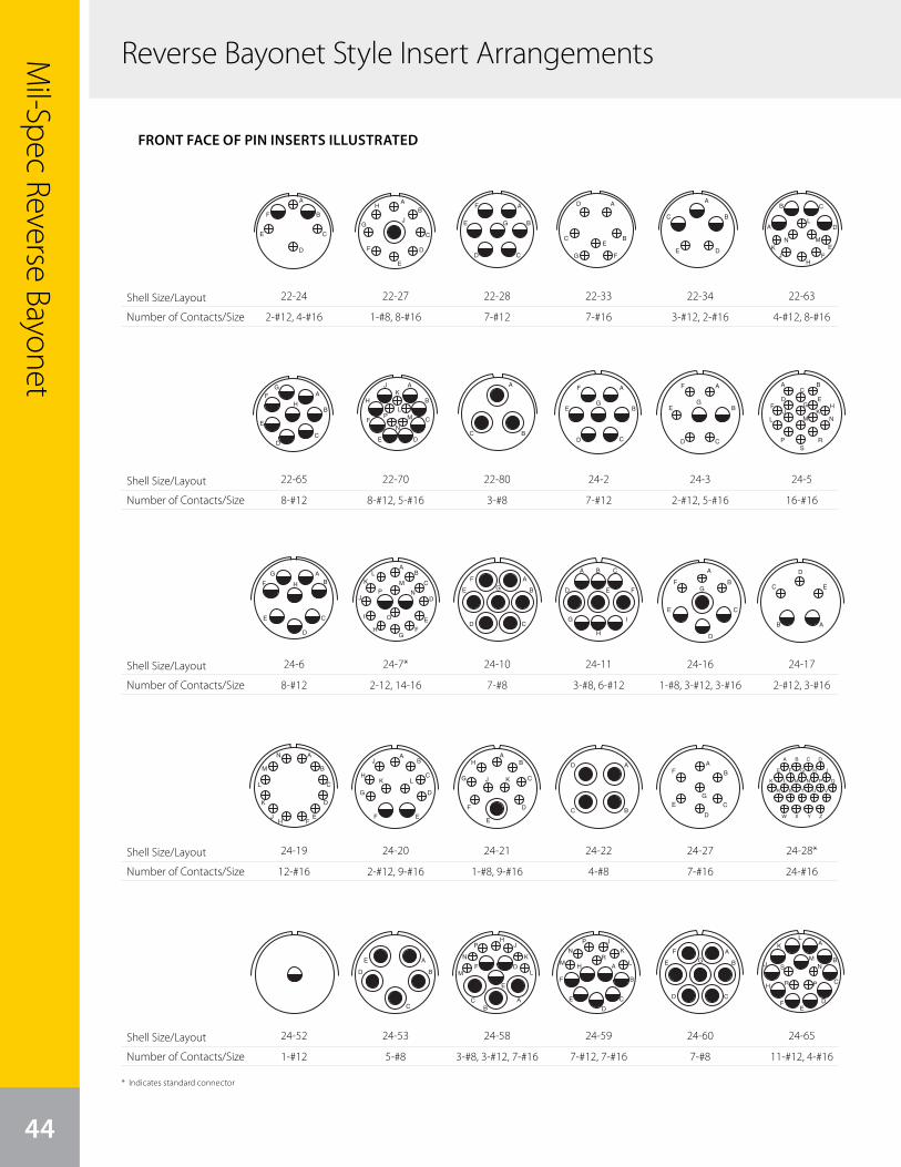
Reverse Bayonet Style Insert Arrangements
44
Mil-Spec Reverse Bayonet
Shell Size/Layout
Number of Contacts/Size
Shell Size/Layout
Number of Contacts/Size
Shell Size/Layout
Number of Contacts/Size
Shell Size/Layout
Number of Contacts/Size
Shell Size/Layout
Number of Contacts/Size
11
A
B
C
D
E
F
AB
C
D
E
F
G
H
J
A
B
C
E
F
G
D
A
BCE
FG
D A
BC
DE
front face of pin insert or rear face of socket insert illustrated
GT Seriescontact arrangements
Insert Arrangement 22-16 22-17 22-18 22-19 22-20
Service Rating A A = D; Bal. = A A, B, F, G, H = D; C, D, E = A A A
Number of Contacts 3 6 1 8 8 14 9
Contact Size 12 16 12 16 16 16 16
Insert Arrangement 22-21 22-22 22-23 22-24 22-27
Service Rating A A H = D; Bal. = A C, D, E = D; A, B, F = A J = D; Bal. = A
Number of Contacts 1 2 4 8 2 4 1 8
Contact Size 0 16 8 12 12 16 8 16
Insert Arrangement 22-28 22-33 22-34 22-63 22-65
Service Rating A A, B, C, D = D; E. F. G = A D A H = D; Bal. = A
Number of Contacts 7 7 3 2 4 8 8*
Contact Size 12 16 12 16 12 16 12 for #14 or 16 wire
* Solderless CONTACT LEGEND 16 12 8 4 0
A
B
C
D
E
F G H
J
AB
C
D
E
F
G
H
J
A
B
C
D
E
F
G
H
AB
C
D
EF
G
H
J
KL
M
N
P
A
B
CDE
F
G H
J
A
B
C A
BC
DA
B
CD
E
FG
H
A
B C
EF
HJ
K
L
MN
D
A
B
CD
E
FG
H
22-24
2-#12, 4-#16
11
A
B
C
D
E
F
AB
C
D
E
F
G
H
J
A
B
C
E
F
G
D
A
BCE
FG
D A
BC
DE
front face of pin insert or rear face of socket insert illustrated
GT Seriescontact arrangements
Insert Arrangement 22-16 22-17 22-18 22-19 22-20
Service Rating A A = D; Bal. = A A, B, F, G, H = D; C, D, E = A A A
Number of Contacts 3 6 1 8 8 14 9
Contact Size 12 16 12 16 16 16 16
Insert Arrangement 22-21 22-22 22-23 22-24 22-27
Service Rating A A H = D; Bal. = A C, D, E = D; A, B, F = A J = D; Bal. = A
Number of Contacts 1 2 4 8 2 4 1 8
Contact Size 0 16 8 12 12 16 8 16
Insert Arrangement 22-28 22-33 22-34 22-63 22-65
Service Rating A A, B, C, D = D; E. F. G = A D A H = D; Bal. = A
Number of Contacts 7 7 3 2 4 8 8*
Contact Size 12 16 12 16 12 16 12 for #14 or 16 wire
* Solderless CONTACT LEGEND 16 12 8 4 0
A
B
C
D
E
F G H
J
AB
C
D
E
F
G
H
J
A
B
C
D
E
F
G
H
AB
C
D
EF
G
H
J
KL
M
N
P
A
B
CDE
F
G H
J
A
B
C A
BC
DA
B
CD
E
FG
H
A
B C
EF
HJ
K
L
MN
D
A
B
CD
E
FG
H
22-65
8-#12
12
AB
C
D
E
AB
C
D
EF
G
H
J
K L
A
B
C
D
EFH
J
K
L
M
N
front face of pin insert or rear face of socket insert illustrated
GT Seriescontact arrangements
Insert Arrangement 22-70 22-80 24-2 24-3 24-5
Service Rating A A D D A
Number of Contacts 8 5 3* 7 2 5 16
Contact Size 12 16 8 for #10 or 12 wire 12 12 16 16
Insert Arrangement 24-6 24-7 24-9 24-10 24-11
Service Rating A, G, H = D; Bal. = A A A A A
Number of Contacts 8 2 14 2 7 3 6
Contact Size 12 12 16 4 8 8 12
Insert Arrangement 24-12 24-16 24-17 24-19 24-20
Service Rating A A, B, F, G = D; C, D, E = A D A D
Number of Contacts 2 3 1 3 3 2 3 12 2 9
Contact Size 4 12 8 12 16 12 16 16 12 16
* Solderless CONTACT LEGEND 16 12 8 4 0
A
B
CD
E
F
G
A
B
C
E
F
G
D
A BC
D EF G H
J KL M N
PS
R
AB
C
D
E
F
G
H
AB
C
D
E
FG
H
J
KL
M
NP
I O
AB
A
B
CD
E
FG
A B C
D E F
G
H
I
A
B
C
D
E
A
B
C
D
E
FG
A
B
C
DE
F
H
JK
LM
N
P
A
BC
24-6
8-#12
12
AB
C
D
E
AB
C
D
EF
G
H
J
K L
A
B
C
D
EFH
J
K
L
M
N
front face of pin insert or rear face of socket insert illustrated
GT Seriescontact arrangements
Insert Arrangement 22-70 22-80 24-2 24-3 24-5
Service Rating A A D D A
Number of Contacts 8 5 3* 7 2 5 16
Contact Size 12 16 8 for #10 or 12 wire 12 12 16 16
Insert Arrangement 24-6 24-7 24-9 24-10 24-11
Service Rating A, G, H = D; Bal. = A A A A A
Number of Contacts 8 2 14 2 7 3 6
Contact Size 12 12 16 4 8 8 12
Insert Arrangement 24-12 24-16 24-17 24-19 24-20
Service Rating A A, B, F, G = D; C, D, E = A D A D
Number of Contacts 2 3 1 3 3 2 3 12 2 9
Contact Size 4 12 8 12 16 12 16 16 12 16
* Solderless CONTACT LEGEND 16 12 8 4 0
A
B
CD
E
F
G
A
B
C
E
F
G
D
A BC
D EF G H
J KL M N
PS
R
AB
C
D
E
F
G
H
AB
C
D
E
FG
H
J
KL
M
NP
I O
AB
A
B
CD
E
FG
A B C
D E F
G
H
I
A
B
C
D
E
A
B
C
D
E
FG
A
B
C
DE
F
H
JK
LM
N
P
A
BC
24-19
12-#16
13
front face of pin insert or rear face of socket insert illustrated
GT Seriescontact arrangements
Insert Arrangement 24-21 24-22 24-27 24-28 24-51
Service Rating D D E Inst. A
Number of Contacts 1 9 4 7 24 5*
Contact Size 8 16 8 16 16 B, E for AN #10 or 12 wireA, C, D for AN #8 wire
Insert Arrangement 24-52 24-53 24-58 24-59 24-60
Service Rating Hi-Volt A A A A
Number of Contacts 1 5* 3 3 7 7 7 7*
Contact Size 12 8 8 12 16 12 16 8 for #10 or 12 wire
Insert Arrangement 24-65 24-66 24-67 24-71 24-75
Service Rating A D Inst. A A
Number of Contacts 11 4 7 19 2* 5* 5 2
Contact Size 12 16 12 12 8 8 for #10 or 12 wire 8 8 for #16 wire
* Solderless CONTACT LEGEND 16 12 8 4 0
A B C D
E F G H J
K L M N P Q
R S T U V
W X Y Z
AB
C
D
E
F
G
H
J K
A
BC
D A
B
C
D
E
F
G
A
B
C
D
E
F
H
J
K
LM
N
P
RA
B
CD
E
FG
A
B
C
DE
F
H
J
KL
MN
PR
S
A
B
CD
E
F
G
90˚
A
B
C
DE
F
G
H
J
KL
M
N
P
R
S
TU
V
A
B
CD
E
FG
A
B
C
D
E
A
B
C
D
E
AB
C
D
E
F
HJ
K
LM
N
P
A
B
CD
E
FG
24-52
1-#12
11
A
B
C
D
E
F
AB
C
D
E
F
G
H
J
A
B
C
E
F
G
D
A
BCE
FG
D A
BC
DE
front face of pin insert or rear face of socket insert illustrated
GT Seriescontact arrangements
Insert Arrangement 22-16 22-17 22-18 22-19 22-20
Service Rating A A = D; Bal. = A A, B, F, G, H = D; C, D, E = A A A
Number of Contacts 3 6 1 8 8 14 9
Contact Size 12 16 12 16 16 16 16
Insert Arrangement 22-21 22-22 22-23 22-24 22-27
Service Rating A A H = D; Bal. = A C, D, E = D; A, B, F = A J = D; Bal. = A
Number of Contacts 1 2 4 8 2 4 1 8
Contact Size 0 16 8 12 12 16 8 16
Insert Arrangement 22-28 22-33 22-34 22-63 22-65
Service Rating A A, B, C, D = D; E. F. G = A D A H = D; Bal. = A
Number of Contacts 7 7 3 2 4 8 8*
Contact Size 12 16 12 16 12 16 12 for #14 or 16 wire
* Solderless CONTACT LEGEND 16 12 8 4 0
A
B
C
D
E
F G H
J
AB
C
D
E
F
G
H
J
A
B
C
D
E
F
G
H
AB
C
D
EF
G
H
J
KL
M
N
P
A
B
CDE
F
G H
J
A
B
C A
BC
DA
B
CD
E
FG
H
A
B C
EF
HJ
K
L
MN
D
A
B
CD
E
FG
H
22-27
1-#8, 8-#16
12
AB
C
D
E
AB
C
D
EF
G
H
J
K L
A
B
C
D
EFH
J
K
L
M
N
front face of pin insert or rear face of socket insert illustrated
GT Seriescontact arrangements
Insert Arrangement 22-70 22-80 24-2 24-3 24-5
Service Rating A A D D A
Number of Contacts 8 5 3* 7 2 5 16
Contact Size 12 16 8 for #10 or 12 wire 12 12 16 16
Insert Arrangement 24-6 24-7 24-9 24-10 24-11
Service Rating A, G, H = D; Bal. = A A A A A
Number of Contacts 8 2 14 2 7 3 6
Contact Size 12 12 16 4 8 8 12
Insert Arrangement 24-12 24-16 24-17 24-19 24-20
Service Rating A A, B, F, G = D; C, D, E = A D A D
Number of Contacts 2 3 1 3 3 2 3 12 2 9
Contact Size 4 12 8 12 16 12 16 16 12 16
* Solderless CONTACT LEGEND 16 12 8 4 0
A
B
CD
E
F
G
A
B
C
E
F
G
D
A BC
D EF G H
J KL M N
PS
R
AB
C
D
E
F
G
H
AB
C
D
E
FG
H
J
KL
M
NP
I O
AB
A
B
CD
E
FG
A B C
D E F
G
H
I
A
B
C
D
E
A
B
C
D
E
FG
A
B
C
DE
F
H
JK
LM
N
P
A
BC
22-70
8-#12, 5-#16
12
AB
C
D
E
AB
C
D
EF
G
H
J
K L
A
B
C
D
EFH
J
K
L
M
N
front face of pin insert or rear face of socket insert illustrated
GT Seriescontact arrangements
Insert Arrangement 22-70 22-80 24-2 24-3 24-5
Service Rating A A D D A
Number of Contacts 8 5 3* 7 2 5 16
Contact Size 12 16 8 for #10 or 12 wire 12 12 16 16
Insert Arrangement 24-6 24-7 24-9 24-10 24-11
Service Rating A, G, H = D; Bal. = A A A A A
Number of Contacts 8 2 14 2 7 3 6
Contact Size 12 12 16 4 8 8 12
Insert Arrangement 24-12 24-16 24-17 24-19 24-20
Service Rating A A, B, F, G = D; C, D, E = A D A D
Number of Contacts 2 3 1 3 3 2 3 12 2 9
Contact Size 4 12 8 12 16 12 16 16 12 16
* Solderless CONTACT LEGEND 16 12 8 4 0
A
B
CD
E
F
G
A
B
C
E
F
G
D
A BC
D EF G H
J KL M N
PS
R
AB
C
D
E
F
G
H
AB
C
D
E
FG
H
J
KL
M
NP
I O
AB
A
B
CD
E
FG
A B C
D E F
G
H
I
A
B
C
D
E
A
B
C
D
E
FG
A
B
C
DE
F
H
JK
LM
N
P
A
BC
24-7*
2-12, 14-16
12
AB
C
D
E
AB
C
D
EF
G
H
J
K L
A
B
C
D
EFH
J
K
L
M
N
front face of pin insert or rear face of socket insert illustrated
GT Seriescontact arrangements
Insert Arrangement 22-70 22-80 24-2 24-3 24-5
Service Rating A A D D A
Number of Contacts 8 5 3* 7 2 5 16
Contact Size 12 16 8 for #10 or 12 wire 12 12 16 16
Insert Arrangement 24-6 24-7 24-9 24-10 24-11
Service Rating A, G, H = D; Bal. = A A A A A
Number of Contacts 8 2 14 2 7 3 6
Contact Size 12 12 16 4 8 8 12
Insert Arrangement 24-12 24-16 24-17 24-19 24-20
Service Rating A A, B, F, G = D; C, D, E = A D A D
Number of Contacts 2 3 1 3 3 2 3 12 2 9
Contact Size 4 12 8 12 16 12 16 16 12 16
* Solderless CONTACT LEGEND 16 12 8 4 0
A
B
CD
E
F
G
A
B
C
E
F
G
D
A BC
D EF G H
J KL M N
PS
R
AB
C
D
E
F
G
H
AB
C
D
E
FG
H
J
KL
M
NP
I O
AB
A
B
CD
E
FG
A B C
D E F
G
H
I
A
B
C
D
E
A
B
C
D
E
FG
A
B
C
DE
F
H
JK
LM
N
P
A
BC
24-20
2-#12, 9-#16
13
front face of pin insert or rear face of socket insert illustrated
GT Seriescontact arrangements
Insert Arrangement 24-21 24-22 24-27 24-28 24-51
Service Rating D D E Inst. A
Number of Contacts 1 9 4 7 24 5*
Contact Size 8 16 8 16 16 B, E for AN #10 or 12 wireA, C, D for AN #8 wire
Insert Arrangement 24-52 24-53 24-58 24-59 24-60
Service Rating Hi-Volt A A A A
Number of Contacts 1 5* 3 3 7 7 7 7*
Contact Size 12 8 8 12 16 12 16 8 for #10 or 12 wire
Insert Arrangement 24-65 24-66 24-67 24-71 24-75
Service Rating A D Inst. A A
Number of Contacts 11 4 7 19 2* 5* 5 2
Contact Size 12 16 12 12 8 8 for #10 or 12 wire 8 8 for #16 wire
* Solderless CONTACT LEGEND 16 12 8 4 0
A B C D
E F G H J
K L M N P Q
R S T U V
W X Y Z
AB
C
D
E
F
G
H
J K
A
BC
D A
B
C
D
E
F
G
A
B
C
D
E
F
H
J
K
LM
N
P
RA
B
CD
E
FG
A
B
C
DE
F
H
J
KL
MN
PR
S
A
B
CD
E
F
G
90˚
A
B
C
DE
F
G
H
J
KL
M
N
P
R
S
TU
V
A
B
CD
E
FG
A
B
C
D
E
A
B
C
D
E
AB
C
D
E
F
HJ
K
LM
N
P
A
B
CD
E
FG
24-53
5-#8
11
A
B
C
D
E
F
AB
C
D
E
F
G
H
J
A
B
C
E
F
G
D
A
BCE
FG
D A
BC
DE
front face of pin insert or rear face of socket insert illustrated
GT Seriescontact arrangements
Insert Arrangement 22-16 22-17 22-18 22-19 22-20
Service Rating A A = D; Bal. = A A, B, F, G, H = D; C, D, E = A A A
Number of Contacts 3 6 1 8 8 14 9
Contact Size 12 16 12 16 16 16 16
Insert Arrangement 22-21 22-22 22-23 22-24 22-27
Service Rating A A H = D; Bal. = A C, D, E = D; A, B, F = A J = D; Bal. = A
Number of Contacts 1 2 4 8 2 4 1 8
Contact Size 0 16 8 12 12 16 8 16
Insert Arrangement 22-28 22-33 22-34 22-63 22-65
Service Rating A A, B, C, D = D; E. F. G = A D A H = D; Bal. = A
Number of Contacts 7 7 3 2 4 8 8*
Contact Size 12 16 12 16 12 16 12 for #14 or 16 wire
* Solderless CONTACT LEGEND 16 12 8 4 0
A
B
C
D
E
F G H
J
AB
C
D
E
F
G
H
J
A
B
C
D
E
F
G
H
AB
C
D
EF
G
H
J
KL
M
N
P
A
B
CDE
F
G H
J
A
B
C A
BC
DA
B
CD
E
FG
H
A
B C
EF
HJ
K
L
MN
D
A
B
CD
E
FG
H
22-28
7-#12
12
AB
C
D
E
AB
C
D
EF
G
H
J
K L
A
B
C
D
EFH
J
K
L
M
N
front face of pin insert or rear face of socket insert illustrated
GT Seriescontact arrangements
Insert Arrangement 22-70 22-80 24-2 24-3 24-5
Service Rating A A D D A
Number of Contacts 8 5 3* 7 2 5 16
Contact Size 12 16 8 for #10 or 12 wire 12 12 16 16
Insert Arrangement 24-6 24-7 24-9 24-10 24-11
Service Rating A, G, H = D; Bal. = A A A A A
Number of Contacts 8 2 14 2 7 3 6
Contact Size 12 12 16 4 8 8 12
Insert Arrangement 24-12 24-16 24-17 24-19 24-20
Service Rating A A, B, F, G = D; C, D, E = A D A D
Number of Contacts 2 3 1 3 3 2 3 12 2 9
Contact Size 4 12 8 12 16 12 16 16 12 16
* Solderless CONTACT LEGEND 16 12 8 4 0
A
B
CD
E
F
G
A
B
C
E
F
G
D
A BC
D EF G H
J KL M N
PS
R
AB
C
D
E
F
G
H
AB
C
D
E
FG
H
J
KL
M
NP
I O
AB
A
B
CD
E
FG
A B C
D E F
G
H
I
A
B
C
D
E
A
B
C
D
E
FG
A
B
C
DE
F
H
JK
LM
N
P
A
BC
22-80
3-#8
12
AB
C
D
E
AB
C
D
EF
G
H
J
K L
A
B
C
D
EFH
J
K
L
M
N
front face of pin insert or rear face of socket insert illustrated
GT Seriescontact arrangements
Insert Arrangement 22-70 22-80 24-2 24-3 24-5
Service Rating A A D D A
Number of Contacts 8 5 3* 7 2 5 16
Contact Size 12 16 8 for #10 or 12 wire 12 12 16 16
Insert Arrangement 24-6 24-7 24-9 24-10 24-11
Service Rating A, G, H = D; Bal. = A A A A A
Number of Contacts 8 2 14 2 7 3 6
Contact Size 12 12 16 4 8 8 12
Insert Arrangement 24-12 24-16 24-17 24-19 24-20
Service Rating A A, B, F, G = D; C, D, E = A D A D
Number of Contacts 2 3 1 3 3 2 3 12 2 9
Contact Size 4 12 8 12 16 12 16 16 12 16
* Solderless CONTACT LEGEND 16 12 8 4 0
A
B
CD
E
F
G
A
B
C
E
F
G
D
A BC
D EF G H
J KL M N
PS
R
AB
C
D
E
F
G
H
AB
C
D
E
FG
H
J
KL
M
NP
I O
AB
A
B
CD
E
FG
A B C
D E F
G
H
I
A
B
C
D
E
A
B
C
D
E
FG
A
B
C
DE
F
H
JK
LM
N
P
A
BC
24-10
7-#8
13
front face of pin insert or rear face of socket insert illustrated
GT Seriescontact arrangements
Insert Arrangement 24-21 24-22 24-27 24-28 24-51
Service Rating D D E Inst. A
Number of Contacts 1 9 4 7 24 5*
Contact Size 8 16 8 16 16 B, E for AN #10 or 12 wireA, C, D for AN #8 wire
Insert Arrangement 24-52 24-53 24-58 24-59 24-60
Service Rating Hi-Volt A A A A
Number of Contacts 1 5* 3 3 7 7 7 7*
Contact Size 12 8 8 12 16 12 16 8 for #10 or 12 wire
Insert Arrangement 24-65 24-66 24-67 24-71 24-75
Service Rating A D Inst. A A
Number of Contacts 11 4 7 19 2* 5* 5 2
Contact Size 12 16 12 12 8 8 for #10 or 12 wire 8 8 for #16 wire
* Solderless CONTACT LEGEND 16 12 8 4 0
A B C D
E F G H J
K L M N P Q
R S T U V
W X Y Z
AB
C
D
E
F
G
H
J K
A
BC
D A
B
C
D
E
F
G
A
B
C
D
E
F
H
J
K
LM
N
P
RA
B
CD
E
FG
A
B
C
DE
F
H
J
KL
MN
PR
S
A
B
CD
E
F
G
90˚
A
B
C
DE
F
G
H
J
KL
M
N
P
R
S
TU
V
A
B
CD
E
FG
A
B
C
D
E
A
B
C
D
E
AB
C
D
E
F
HJ
K
LM
N
P
A
B
CD
E
FG
24-21
1-#8, 9-#16
13
front face of pin insert or rear face of socket insert illustrated
GT Seriescontact arrangements
Insert Arrangement 24-21 24-22 24-27 24-28 24-51
Service Rating D D E Inst. A
Number of Contacts 1 9 4 7 24 5*
Contact Size 8 16 8 16 16 B, E for AN #10 or 12 wireA, C, D for AN #8 wire
Insert Arrangement 24-52 24-53 24-58 24-59 24-60
Service Rating Hi-Volt A A A A
Number of Contacts 1 5* 3 3 7 7 7 7*
Contact Size 12 8 8 12 16 12 16 8 for #10 or 12 wire
Insert Arrangement 24-65 24-66 24-67 24-71 24-75
Service Rating A D Inst. A A
Number of Contacts 11 4 7 19 2* 5* 5 2
Contact Size 12 16 12 12 8 8 for #10 or 12 wire 8 8 for #16 wire
* Solderless CONTACT LEGEND 16 12 8 4 0
A B C D
E F G H J
K L M N P Q
R S T U V
W X Y Z
AB
C
D
E
F
G
H
J K
A
BC
D A
B
C
D
E
F
G
A
B
C
D
E
F
H
J
K
LM
N
P
RA
B
CD
E
FG
A
B
C
DE
F
H
J
KL
MN
PR
S
A
B
CD
E
F
G
90˚
A
B
C
DE
F
G
H
J
KL
M
N
P
R
S
TU
V
A
B
CD
E
FG
A
B
C
D
E
A
B
C
D
E
AB
C
D
E
F
HJ
K
LM
N
P
A
B
CD
E
FG
24-58
3-#8, 3-#12, 7-#16
11
A
B
C
D
E
F
AB
C
D
E
F
G
H
J
A
B
C
E
F
G
D
A
BCE
FG
D A
BC
DE
front face of pin insert or rear face of socket insert illustrated
GT Seriescontact arrangements
Insert Arrangement 22-16 22-17 22-18 22-19 22-20
Service Rating A A = D; Bal. = A A, B, F, G, H = D; C, D, E = A A A
Number of Contacts 3 6 1 8 8 14 9
Contact Size 12 16 12 16 16 16 16
Insert Arrangement 22-21 22-22 22-23 22-24 22-27
Service Rating A A H = D; Bal. = A C, D, E = D; A, B, F = A J = D; Bal. = A
Number of Contacts 1 2 4 8 2 4 1 8
Contact Size 0 16 8 12 12 16 8 16
Insert Arrangement 22-28 22-33 22-34 22-63 22-65
Service Rating A A, B, C, D = D; E. F. G = A D A H = D; Bal. = A
Number of Contacts 7 7 3 2 4 8 8*
Contact Size 12 16 12 16 12 16 12 for #14 or 16 wire
* Solderless CONTACT LEGEND 16 12 8 4 0
A
B
C
D
E
F G H
J
AB
C
D
E
F
G
H
J
A
B
C
D
E
F
G
H
AB
C
D
EF
G
H
J
KL
M
N
P
A
B
CDE
F
G H
J
A
B
C A
BC
DA
B
CD
E
FG
H
A
B C
EF
HJ
K
L
MN
D
A
B
CD
E
FG
H
22-33
7-#16
12
AB
C
D
E
AB
C
D
EF
G
H
J
K L
A
B
C
D
EFH
J
K
L
M
N
front face of pin insert or rear face of socket insert illustrated
GT Seriescontact arrangements
Insert Arrangement 22-70 22-80 24-2 24-3 24-5
Service Rating A A D D A
Number of Contacts 8 5 3* 7 2 5 16
Contact Size 12 16 8 for #10 or 12 wire 12 12 16 16
Insert Arrangement 24-6 24-7 24-9 24-10 24-11
Service Rating A, G, H = D; Bal. = A A A A A
Number of Contacts 8 2 14 2 7 3 6
Contact Size 12 12 16 4 8 8 12
Insert Arrangement 24-12 24-16 24-17 24-19 24-20
Service Rating A A, B, F, G = D; C, D, E = A D A D
Number of Contacts 2 3 1 3 3 2 3 12 2 9
Contact Size 4 12 8 12 16 12 16 16 12 16
* Solderless CONTACT LEGEND 16 12 8 4 0
A
B
CD
E
F
G
A
B
C
E
F
G
D
A BC
D EF G H
J KL M N
PS
R
AB
C
D
E
F
G
H
AB
C
D
E
FG
H
J
KL
M
NP
I O
AB
A
B
CD
E
FG
A B C
D E F
G
H
I
A
B
C
D
E
A
B
C
D
E
FG
A
B
C
DE
F
H
JK
LM
N
P
A
BC
24-2
7-#12
12
AB
C
D
E
AB
C
D
EF
G
H
J
K L
A
B
C
D
EFH
J
K
L
M
N
front face of pin insert or rear face of socket insert illustrated
GT Seriescontact arrangements
Insert Arrangement 22-70 22-80 24-2 24-3 24-5
Service Rating A A D D A
Number of Contacts 8 5 3* 7 2 5 16
Contact Size 12 16 8 for #10 or 12 wire 12 12 16 16
Insert Arrangement 24-6 24-7 24-9 24-10 24-11
Service Rating A, G, H = D; Bal. = A A A A A
Number of Contacts 8 2 14 2 7 3 6
Contact Size 12 12 16 4 8 8 12
Insert Arrangement 24-12 24-16 24-17 24-19 24-20
Service Rating A A, B, F, G = D; C, D, E = A D A D
Number of Contacts 2 3 1 3 3 2 3 12 2 9
Contact Size 4 12 8 12 16 12 16 16 12 16
* Solderless CONTACT LEGEND 16 12 8 4 0
A
B
CD
E
F
G
A
B
C
E
F
G
D
A BC
D EF G H
J KL M N
PS
R
AB
C
D
E
F
G
H
AB
C
D
E
FG
H
J
KL
M
NP
I O
AB
A
B
CD
E
FG
A B C
D E F
G
H
I
A
B
C
D
E
A
B
C
D
E
FG
A
B
C
DE
F
H
JK
LM
N
P
A
BC
24-11
3-#8, 6-#12
13
front face of pin insert or rear face of socket insert illustrated
GT Seriescontact arrangements
Insert Arrangement 24-21 24-22 24-27 24-28 24-51
Service Rating D D E Inst. A
Number of Contacts 1 9 4 7 24 5*
Contact Size 8 16 8 16 16 B, E for AN #10 or 12 wireA, C, D for AN #8 wire
Insert Arrangement 24-52 24-53 24-58 24-59 24-60
Service Rating Hi-Volt A A A A
Number of Contacts 1 5* 3 3 7 7 7 7*
Contact Size 12 8 8 12 16 12 16 8 for #10 or 12 wire
Insert Arrangement 24-65 24-66 24-67 24-71 24-75
Service Rating A D Inst. A A
Number of Contacts 11 4 7 19 2* 5* 5 2
Contact Size 12 16 12 12 8 8 for #10 or 12 wire 8 8 for #16 wire
* Solderless CONTACT LEGEND 16 12 8 4 0
A B C D
E F G H J
K L M N P Q
R S T U V
W X Y Z
AB
C
D
E
F
G
H
J K
A
BC
D A
B
C
D
E
F
G
A
B
C
D
E
F
H
J
K
LM
N
P
RA
B
CD
E
FG
A
B
C
DE
F
H
J
KL
MN
PR
S
A
B
CD
E
F
G
90˚
A
B
C
DE
F
G
H
J
KL
M
N
P
R
S
TU
V
A
B
CD
E
FG
A
B
C
D
E
A
B
C
D
E
AB
C
D
E
F
HJ
K
LM
N
P
A
B
CD
E
FG
24-22
4-#8
13
front face of pin insert or rear face of socket insert illustrated
GT Seriescontact arrangements
Insert Arrangement 24-21 24-22 24-27 24-28 24-51
Service Rating D D E Inst. A
Number of Contacts 1 9 4 7 24 5*
Contact Size 8 16 8 16 16 B, E for AN #10 or 12 wireA, C, D for AN #8 wire
Insert Arrangement 24-52 24-53 24-58 24-59 24-60
Service Rating Hi-Volt A A A A
Number of Contacts 1 5* 3 3 7 7 7 7*
Contact Size 12 8 8 12 16 12 16 8 for #10 or 12 wire
Insert Arrangement 24-65 24-66 24-67 24-71 24-75
Service Rating A D Inst. A A
Number of Contacts 11 4 7 19 2* 5* 5 2
Contact Size 12 16 12 12 8 8 for #10 or 12 wire 8 8 for #16 wire
* Solderless CONTACT LEGEND 16 12 8 4 0
A B C D
E F G H J
K L M N P Q
R S T U V
W X Y Z
AB
C
D
E
F
G
H
J K
A
BC
D A
B
C
D
E
F
G
A
B
C
D
E
F
H
J
K
LM
N
P
RA
B
CD
E
FG
A
B
C
DE
F
H
J
KL
MN
PR
S
A
B
CD
E
F
G
90˚
A
B
C
DE
F
G
H
J
KL
M
N
P
R
S
TU
V
A
B
CD
E
FG
A
B
C
D
E
A
B
C
D
E
AB
C
D
E
F
HJ
K
LM
N
P
A
B
CD
E
FG
24-59
7-#12, 7-#16
11
A
B
C
D
E
F
AB
C
D
E
F
G
H
J
A
B
C
E
F
G
D
A
BCE
FG
D A
BC
DE
front face of pin insert or rear face of socket insert illustrated
GT Seriescontact arrangements
Insert Arrangement 22-16 22-17 22-18 22-19 22-20
Service Rating A A = D; Bal. = A A, B, F, G, H = D; C, D, E = A A A
Number of Contacts 3 6 1 8 8 14 9
Contact Size 12 16 12 16 16 16 16
Insert Arrangement 22-21 22-22 22-23 22-24 22-27
Service Rating A A H = D; Bal. = A C, D, E = D; A, B, F = A J = D; Bal. = A
Number of Contacts 1 2 4 8 2 4 1 8
Contact Size 0 16 8 12 12 16 8 16
Insert Arrangement 22-28 22-33 22-34 22-63 22-65
Service Rating A A, B, C, D = D; E. F. G = A D A H = D; Bal. = A
Number of Contacts 7 7 3 2 4 8 8*
Contact Size 12 16 12 16 12 16 12 for #14 or 16 wire
* Solderless CONTACT LEGEND 16 12 8 4 0
A
B
C
D
E
F G H
J
AB
C
D
E
F
G
H
J
A
B
C
D
E
F
G
H
AB
C
D
EF
G
H
J
KL
M
N
P
A
B
CDE
F
G H
J
A
B
C A
BC
DA
B
CD
E
FG
H
A
B C
EF
HJ
K
L
MN
D
A
B
CD
E
FG
H
22-34
3-#12, 2-#16
12
AB
C
D
E
AB
C
D
EF
G
H
J
K L
A
B
C
D
EFH
J
K
L
M
N
front face of pin insert or rear face of socket insert illustrated
GT Seriescontact arrangements
Insert Arrangement 22-70 22-80 24-2 24-3 24-5
Service Rating A A D D A
Number of Contacts 8 5 3* 7 2 5 16
Contact Size 12 16 8 for #10 or 12 wire 12 12 16 16
Insert Arrangement 24-6 24-7 24-9 24-10 24-11
Service Rating A, G, H = D; Bal. = A A A A A
Number of Contacts 8 2 14 2 7 3 6
Contact Size 12 12 16 4 8 8 12
Insert Arrangement 24-12 24-16 24-17 24-19 24-20
Service Rating A A, B, F, G = D; C, D, E = A D A D
Number of Contacts 2 3 1 3 3 2 3 12 2 9
Contact Size 4 12 8 12 16 12 16 16 12 16
* Solderless CONTACT LEGEND 16 12 8 4 0
A
B
CD
E
F
G
A
B
C
E
F
G
D
A BC
D EF G H
J KL M N
PS
R
AB
C
D
E
F
G
H
AB
C
D
E
FG
H
J
KL
M
NP
I O
AB
A
B
CD
E
FG
A B C
D E F
G
H
I
A
B
C
D
E
A
B
C
D
E
FG
A
B
C
DE
F
H
JK
LM
N
P
A
BC
24-3
2-#12, 5-#16
12
AB
C
D
E
AB
C
D
EF
G
H
J
K L
A
B
C
D
EFH
J
K
L
M
N
front face of pin insert or rear face of socket insert illustrated
GT Seriescontact arrangements
Insert Arrangement 22-70 22-80 24-2 24-3 24-5
Service Rating A A D D A
Number of Contacts 8 5 3* 7 2 5 16
Contact Size 12 16 8 for #10 or 12 wire 12 12 16 16
Insert Arrangement 24-6 24-7 24-9 24-10 24-11
Service Rating A, G, H = D; Bal. = A A A A A
Number of Contacts 8 2 14 2 7 3 6
Contact Size 12 12 16 4 8 8 12
Insert Arrangement 24-12 24-16 24-17 24-19 24-20
Service Rating A A, B, F, G = D; C, D, E = A D A D
Number of Contacts 2 3 1 3 3 2 3 12 2 9
Contact Size 4 12 8 12 16 12 16 16 12 16
* Solderless CONTACT LEGEND 16 12 8 4 0
A
B
CD
E
F
G
A
B
C
E
F
G
D
A BC
D EF G H
J KL M N
PS
R
AB
C
D
E
F
G
H
AB
C
D
E
FG
H
J
KL
M
NP
I O
AB
A
B
CD
E
FG
A B C
D E F
G
H
I
A
B
C
D
E
A
B
C
D
E
FG
A
B
C
DE
F
H
JK
LM
N
P
A
BC
24-16
1-#8, 3-#12, 3-#16
13
front face of pin insert or rear face of socket insert illustrated
GT Seriescontact arrangements
Insert Arrangement 24-21 24-22 24-27 24-28 24-51
Service Rating D D E Inst. A
Number of Contacts 1 9 4 7 24 5*
Contact Size 8 16 8 16 16 B, E for AN #10 or 12 wireA, C, D for AN #8 wire
Insert Arrangement 24-52 24-53 24-58 24-59 24-60
Service Rating Hi-Volt A A A A
Number of Contacts 1 5* 3 3 7 7 7 7*
Contact Size 12 8 8 12 16 12 16 8 for #10 or 12 wire
Insert Arrangement 24-65 24-66 24-67 24-71 24-75
Service Rating A D Inst. A A
Number of Contacts 11 4 7 19 2* 5* 5 2
Contact Size 12 16 12 12 8 8 for #10 or 12 wire 8 8 for #16 wire
* Solderless CONTACT LEGEND 16 12 8 4 0
A B C D
E F G H J
K L M N P Q
R S T U V
W X Y Z
AB
C
D
E
F
G
H
J K
A
BC
D A
B
C
D
E
F
G
A
B
C
D
E
F
H
J
K
LM
N
P
RA
B
CD
E
FG
A
B
C
DE
F
H
J
KL
MN
PR
S
A
B
CD
E
F
G
90˚
A
B
C
DE
F
G
H
J
KL
M
N
P
R
S
TU
V
A
B
CD
E
FG
A
B
C
D
E
A
B
C
D
E
AB
C
D
E
F
HJ
K
LM
N
P
A
B
CD
E
FG
24-27
7-#16
13
front face of pin insert or rear face of socket insert illustrated
GT Seriescontact arrangements
Insert Arrangement 24-21 24-22 24-27 24-28 24-51
Service Rating D D E Inst. A
Number of Contacts 1 9 4 7 24 5*
Contact Size 8 16 8 16 16 B, E for AN #10 or 12 wireA, C, D for AN #8 wire
Insert Arrangement 24-52 24-53 24-58 24-59 24-60
Service Rating Hi-Volt A A A A
Number of Contacts 1 5* 3 3 7 7 7 7*
Contact Size 12 8 8 12 16 12 16 8 for #10 or 12 wire
Insert Arrangement 24-65 24-66 24-67 24-71 24-75
Service Rating A D Inst. A A
Number of Contacts 11 4 7 19 2* 5* 5 2
Contact Size 12 16 12 12 8 8 for #10 or 12 wire 8 8 for #16 wire
* Solderless CONTACT LEGEND 16 12 8 4 0
A B C D
E F G H J
K L M N P Q
R S T U V
W X Y Z
AB
C
D
E
F
G
H
J K
A
BC
D A
B
C
D
E
F
G
A
B
C
D
E
F
H
J
K
LM
N
P
RA
B
CD
E
FG
A
B
C
DE
F
H
J
KL
MN
PR
S
A
B
CD
E
F
G
90˚
A
B
C
DE
F
G
H
J
KL
M
N
P
R
S
TU
V
A
B
CD
E
FG
A
B
C
D
E
A
B
C
D
E
AB
C
D
E
F
HJ
K
LM
N
P
A
B
CD
E
FG
24-60
7-#8
11
A
B
C
D
E
F
AB
C
D
E
F
G
H
J
A
B
C
E
F
G
D
A
BCE
FG
D A
BC
DE
front face of pin insert or rear face of socket insert illustrated
GT Seriescontact arrangements
Insert Arrangement 22-16 22-17 22-18 22-19 22-20
Service Rating A A = D; Bal. = A A, B, F, G, H = D; C, D, E = A A A
Number of Contacts 3 6 1 8 8 14 9
Contact Size 12 16 12 16 16 16 16
Insert Arrangement 22-21 22-22 22-23 22-24 22-27
Service Rating A A H = D; Bal. = A C, D, E = D; A, B, F = A J = D; Bal. = A
Number of Contacts 1 2 4 8 2 4 1 8
Contact Size 0 16 8 12 12 16 8 16
Insert Arrangement 22-28 22-33 22-34 22-63 22-65
Service Rating A A, B, C, D = D; E. F. G = A D A H = D; Bal. = A
Number of Contacts 7 7 3 2 4 8 8*
Contact Size 12 16 12 16 12 16 12 for #14 or 16 wire
* Solderless CONTACT LEGEND 16 12 8 4 0
A
B
C
D
E
F G H
J
AB
C
D
E
F
G
H
J
A
B
C
D
E
F
G
H
AB
C
D
EF
G
H
J
KL
M
N
P
A
B
CDE
F
G H
J
A
B
C A
BC
DA
B
CD
E
FG
H
A
B C
EF
HJ
K
L
MN
D
A
B
CD
E
FG
H
22-63
4-#12, 8-#16
12
AB
C
D
E
AB
C
D
EF
G
H
J
K L
A
B
C
D
EFH
J
K
L
M
N
front face of pin insert or rear face of socket insert illustrated
GT Seriescontact arrangements
Insert Arrangement 22-70 22-80 24-2 24-3 24-5
Service Rating A A D D A
Number of Contacts 8 5 3* 7 2 5 16
Contact Size 12 16 8 for #10 or 12 wire 12 12 16 16
Insert Arrangement 24-6 24-7 24-9 24-10 24-11
Service Rating A, G, H = D; Bal. = A A A A A
Number of Contacts 8 2 14 2 7 3 6
Contact Size 12 12 16 4 8 8 12
Insert Arrangement 24-12 24-16 24-17 24-19 24-20
Service Rating A A, B, F, G = D; C, D, E = A D A D
Number of Contacts 2 3 1 3 3 2 3 12 2 9
Contact Size 4 12 8 12 16 12 16 16 12 16
* Solderless CONTACT LEGEND 16 12 8 4 0
A
B
CD
E
F
G
A
B
C
E
F
G
D
A BC
D EF G H
J KL M N
PS
R
AB
C
D
E
F
G
H
AB
C
D
E
FG
H
J
KL
M
NP
I O
AB
A
B
CD
E
FG
A B C
D E F
G
H
I
A
B
C
D
E
A
B
C
D
E
FG
A
B
C
DE
F
H
JK
LM
N
P
A
BC
24-5
16-#16
12
AB
C
D
E
AB
C
D
EF
G
H
J
K L
A
B
C
D
EFH
J
K
L
M
N
front face of pin insert or rear face of socket insert illustrated
GT Seriescontact arrangements
Insert Arrangement 22-70 22-80 24-2 24-3 24-5
Service Rating A A D D A
Number of Contacts 8 5 3* 7 2 5 16
Contact Size 12 16 8 for #10 or 12 wire 12 12 16 16
Insert Arrangement 24-6 24-7 24-9 24-10 24-11
Service Rating A, G, H = D; Bal. = A A A A A
Number of Contacts 8 2 14 2 7 3 6
Contact Size 12 12 16 4 8 8 12
Insert Arrangement 24-12 24-16 24-17 24-19 24-20
Service Rating A A, B, F, G = D; C, D, E = A D A D
Number of Contacts 2 3 1 3 3 2 3 12 2 9
Contact Size 4 12 8 12 16 12 16 16 12 16
* Solderless CONTACT LEGEND 16 12 8 4 0
A
B
CD
E
F
G
A
B
C
E
F
G
D
A BC
D EF G H
J KL M N
PS
R
AB
C
D
E
F
G
H
AB
C
D
E
FG
H
J
KL
M
NP
I O
AB
A
B
CD
E
FG
A B C
D E F
G
H
I
A
B
C
D
E
A
B
C
D
E
FG
A
B
C
DE
F
H
JK
LM
N
P
A
BC
24-17
2-#12, 3-#16
13
front face of pin insert or rear face of socket insert illustrated
GT Seriescontact arrangements
Insert Arrangement 24-21 24-22 24-27 24-28 24-51
Service Rating D D E Inst. A
Number of Contacts 1 9 4 7 24 5*
Contact Size 8 16 8 16 16 B, E for AN #10 or 12 wireA, C, D for AN #8 wire
Insert Arrangement 24-52 24-53 24-58 24-59 24-60
Service Rating Hi-Volt A A A A
Number of Contacts 1 5* 3 3 7 7 7 7*
Contact Size 12 8 8 12 16 12 16 8 for #10 or 12 wire
Insert Arrangement 24-65 24-66 24-67 24-71 24-75
Service Rating A D Inst. A A
Number of Contacts 11 4 7 19 2* 5* 5 2
Contact Size 12 16 12 12 8 8 for #10 or 12 wire 8 8 for #16 wire
* Solderless CONTACT LEGEND 16 12 8 4 0
A B C D
E F G H J
K L M N P Q
R S T U V
W X Y Z
AB
C
D
E
F
G
H
J K
A
BC
D A
B
C
D
E
F
G
A
B
C
D
E
F
H
J
K
LM
N
P
RA
B
CD
E
FG
A
B
C
DE
F
H
J
KL
MN
PR
S
A
B
CD
E
F
G
90˚
A
B
C
DE
F
G
H
J
KL
M
N
P
R
S
TU
V
A
B
CD
E
FG
A
B
C
D
E
A
B
C
D
E
AB
C
D
E
F
HJ
K
LM
N
P
A
B
CD
E
FG
24-28*
24-#16
13
front face of pin insert or rear face of socket insert illustrated
GT Seriescontact arrangements
Insert Arrangement 24-21 24-22 24-27 24-28 24-51
Service Rating D D E Inst. A
Number of Contacts 1 9 4 7 24 5*
Contact Size 8 16 8 16 16 B, E for AN #10 or 12 wireA, C, D for AN #8 wire
Insert Arrangement 24-52 24-53 24-58 24-59 24-60
Service Rating Hi-Volt A A A A
Number of Contacts 1 5* 3 3 7 7 7 7*
Contact Size 12 8 8 12 16 12 16 8 for #10 or 12 wire
Insert Arrangement 24-65 24-66 24-67 24-71 24-75
Service Rating A D Inst. A A
Number of Contacts 11 4 7 19 2* 5* 5 2
Contact Size 12 16 12 12 8 8 for #10 or 12 wire 8 8 for #16 wire
* Solderless CONTACT LEGEND 16 12 8 4 0
A B C D
E F G H J
K L M N P Q
R S T U V
W X Y Z
AB
C
D
E
F
G
H
J K
A
BC
D A
B
C
D
E
F
G
A
B
C
D
E
F
H
J
K
LM
N
P
RA
B
CD
E
FG
A
B
C
DE
F
H
J
KL
MN
PR
S
A
B
CD
E
F
G
90˚
A
B
C
DE
F
G
H
J
KL
M
N
P
R
S
TU
V
A
B
CD
E
FG
A
B
C
D
E
A
B
C
D
E
AB
C
D
E
F
HJ
K
LM
N
P
A
B
CD
E
FG
24-65
11-#12, 4-#16
* Indicates standard connector
FRONT FACE OF PIN INSERTS ILLUSTRATED
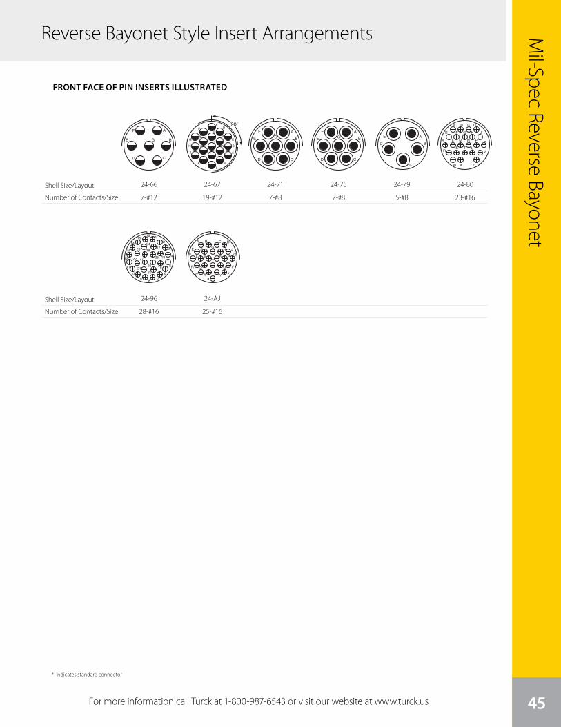
Reverse Bayonet Style Insert Arrangements
45
Mil-Spec Reverse Bayonet
For more information call Turck at 1-800-987-6543 or visit our website at www.turck.us
Shell Size/Layout
Number of Contacts/Size
Shell Size/Layout
Number of Contacts/Size13
front face of pin insert or rear face of socket insert illustrated
GT Seriescontact arrangements
Insert Arrangement 24-21 24-22 24-27 24-28 24-51
Service Rating D D E Inst. A
Number of Contacts 1 9 4 7 24 5*
Contact Size 8 16 8 16 16 B, E for AN #10 or 12 wireA, C, D for AN #8 wire
Insert Arrangement 24-52 24-53 24-58 24-59 24-60
Service Rating Hi-Volt A A A A
Number of Contacts 1 5* 3 3 7 7 7 7*
Contact Size 12 8 8 12 16 12 16 8 for #10 or 12 wire
Insert Arrangement 24-65 24-66 24-67 24-71 24-75
Service Rating A D Inst. A A
Number of Contacts 11 4 7 19 2* 5* 5 2
Contact Size 12 16 12 12 8 8 for #10 or 12 wire 8 8 for #16 wire
* Solderless CONTACT LEGEND 16 12 8 4 0
A B C D
E F G H J
K L M N P Q
R S T U V
W X Y Z
AB
C
D
E
F
G
H
J K
A
BC
D A
B
C
D
E
F
G
A
B
C
D
E
F
H
J
K
LM
N
P
RA
B
CD
E
FG
A
B
C
DE
F
H
J
KL
MN
PR
S
A
B
CD
E
F
G
90˚
A
B
C
DE
F
G
H
J
KL
M
N
P
R
S
TU
V
A
B
CD
E
FG
A
B
C
D
E
A
B
C
D
E
AB
C
D
E
F
HJ
K
LM
N
P
A
B
CD
E
FG
24-66
7-#12
14
front face of pin insert or rear face of socket insert illustrated
GT Seriescontact arrangements
Insert Arrangement 24-79 24-80 24-84 24-96 24-AJ
Service Rating A Inst. A Inst. A
Number of Contacts 5 23 1 18 28 25
Contact Size 8 16 12 12 (Coax) RG-188/U 16 16
or RG-174/U
Insert Arrangement 28-1 28-2 28-3 28-4
Service Rating A, J, E = D; Bal. = A D E G, P, S = E; Bal. = D
Number of Contacts 3 6 2 12 3 2 7
Contact Size 8 12 12 16 8 12 16
Insert Arrangement 28-5 28-6 28-7 28-8
Service Rating D D D L, M = E; B = D; Bal. = A
Number of Contacts 2 1 2 3 2 2 10
Contact Size 4 12 16 4 4 12 16
CONTACT LEGEND 16 12 8 4 0
A B
C
DEF
G
H
J
A
B
C
D
EF
G
H
J
K
L
M
N
P
A
BC
A B
C DP
S
E FG
A
B
CD
E
A
BC
AB
A
B
C
D
E
A B C D
E F G H J
K L M N P Q
RS T U
V
W X Z
90˚
A
B
C
DE
F
G
H
J
KL
M
N
P
R
S
TU
V
12
3
4
5
6
789
10
11
12
13
14
1516
17
18
1920
21
22
23
24
25
26
27
28
A B C D
E FG
H JK
L M N PQ
R S
T
U V
W X ZYa
A
B
C
D
E
F
G
H
J
K
L
M
24-96
28-#1613
front face of pin insert or rear face of socket insert illustrated
GT Seriescontact arrangements
Insert Arrangement 24-21 24-22 24-27 24-28 24-51
Service Rating D D E Inst. A
Number of Contacts 1 9 4 7 24 5*
Contact Size 8 16 8 16 16 B, E for AN #10 or 12 wireA, C, D for AN #8 wire
Insert Arrangement 24-52 24-53 24-58 24-59 24-60
Service Rating Hi-Volt A A A A
Number of Contacts 1 5* 3 3 7 7 7 7*
Contact Size 12 8 8 12 16 12 16 8 for #10 or 12 wire
Insert Arrangement 24-65 24-66 24-67 24-71 24-75
Service Rating A D Inst. A A
Number of Contacts 11 4 7 19 2* 5* 5 2
Contact Size 12 16 12 12 8 8 for #10 or 12 wire 8 8 for #16 wire
* Solderless CONTACT LEGEND 16 12 8 4 0
A B C D
E F G H J
K L M N P Q
R S T U V
W X Y Z
AB
C
D
E
F
G
H
J K
A
BC
D A
B
C
D
E
F
G
A
B
C
D
E
F
H
J
K
LM
N
P
RA
B
CD
E
FG
A
B
C
DE
F
H
J
KL
MN
PR
S
A
B
CD
E
F
G
90˚
A
B
C
DE
F
G
H
J
KL
M
N
P
R
S
TU
V
A
B
CD
E
FG
A
B
C
D
E
A
B
C
D
E
AB
C
D
E
F
HJ
K
LM
N
P
A
B
CD
E
FG
24-67
19-#12
14
front face of pin insert or rear face of socket insert illustrated
GT Seriescontact arrangements
Insert Arrangement 24-79 24-80 24-84 24-96 24-AJ
Service Rating A Inst. A Inst. A
Number of Contacts 5 23 1 18 28 25
Contact Size 8 16 12 12 (Coax) RG-188/U 16 16
or RG-174/U
Insert Arrangement 28-1 28-2 28-3 28-4
Service Rating A, J, E = D; Bal. = A D E G, P, S = E; Bal. = D
Number of Contacts 3 6 2 12 3 2 7
Contact Size 8 12 12 16 8 12 16
Insert Arrangement 28-5 28-6 28-7 28-8
Service Rating D D D L, M = E; B = D; Bal. = A
Number of Contacts 2 1 2 3 2 2 10
Contact Size 4 12 16 4 4 12 16
CONTACT LEGEND 16 12 8 4 0
A B
C
DEF
G
H
J
A
B
C
D
EF
G
H
J
K
L
M
N
P
A
BC
A B
C DP
S
E FG
A
B
CD
E
A
BC
AB
A
B
C
D
E
A B C D
E F G H J
K L M N P Q
RS T U
V
W X Z
90˚
A
B
C
DE
F
G
H
J
KL
M
N
P
R
S
TU
V
12
3
4
5
6
789
10
11
12
13
14
1516
17
18
1920
21
22
23
24
25
26
27
28
A B C D
E FG
H JK
L M N PQ
R S
T
U V
W X ZYa
A
B
C
D
E
F
G
H
J
K
L
M
24-AJ
25-#1613
front face of pin insert or rear face of socket insert illustrated
GT Seriescontact arrangements
Insert Arrangement 24-21 24-22 24-27 24-28 24-51
Service Rating D D E Inst. A
Number of Contacts 1 9 4 7 24 5*
Contact Size 8 16 8 16 16 B, E for AN #10 or 12 wireA, C, D for AN #8 wire
Insert Arrangement 24-52 24-53 24-58 24-59 24-60
Service Rating Hi-Volt A A A A
Number of Contacts 1 5* 3 3 7 7 7 7*
Contact Size 12 8 8 12 16 12 16 8 for #10 or 12 wire
Insert Arrangement 24-65 24-66 24-67 24-71 24-75
Service Rating A D Inst. A A
Number of Contacts 11 4 7 19 2* 5* 5 2
Contact Size 12 16 12 12 8 8 for #10 or 12 wire 8 8 for #16 wire
* Solderless CONTACT LEGEND 16 12 8 4 0
A B C D
E F G H J
K L M N P Q
R S T U V
W X Y Z
AB
C
D
E
F
G
H
J K
A
BC
D A
B
C
D
E
F
G
A
B
C
D
E
F
H
J
K
LM
N
P
RA
B
CD
E
FG
A
B
C
DE
F
H
J
KL
MN
PR
S
A
B
CD
E
F
G
90˚
A
B
C
DE
F
G
H
J
KL
M
N
P
R
S
TU
V
A
B
CD
E
FG
A
B
C
D
E
A
B
C
D
E
AB
C
D
E
F
HJ
K
LM
N
P
A
B
CD
E
FG
24-71
7-#8
13
front face of pin insert or rear face of socket insert illustrated
GT Seriescontact arrangements
Insert Arrangement 24-21 24-22 24-27 24-28 24-51
Service Rating D D E Inst. A
Number of Contacts 1 9 4 7 24 5*
Contact Size 8 16 8 16 16 B, E for AN #10 or 12 wireA, C, D for AN #8 wire
Insert Arrangement 24-52 24-53 24-58 24-59 24-60
Service Rating Hi-Volt A A A A
Number of Contacts 1 5* 3 3 7 7 7 7*
Contact Size 12 8 8 12 16 12 16 8 for #10 or 12 wire
Insert Arrangement 24-65 24-66 24-67 24-71 24-75
Service Rating A D Inst. A A
Number of Contacts 11 4 7 19 2* 5* 5 2
Contact Size 12 16 12 12 8 8 for #10 or 12 wire 8 8 for #16 wire
* Solderless CONTACT LEGEND 16 12 8 4 0
A B C D
E F G H J
K L M N P Q
R S T U V
W X Y Z
AB
C
D
E
F
G
H
J K
A
BC
D A
B
C
D
E
F
G
A
B
C
D
E
F
H
J
K
LM
N
P
RA
B
CD
E
FG
A
B
C
DE
F
H
J
KL
MN
PR
S
A
B
CD
E
F
G
90˚
A
B
C
DE
F
G
H
J
KL
M
N
P
R
S
TU
V
A
B
CD
E
FG
A
B
C
D
E
A
B
C
D
E
AB
C
D
E
F
HJ
K
LM
N
P
A
B
CD
E
FG
24-75
7-#8
14
front face of pin insert or rear face of socket insert illustrated
GT Seriescontact arrangements
Insert Arrangement 24-79 24-80 24-84 24-96 24-AJ
Service Rating A Inst. A Inst. A
Number of Contacts 5 23 1 18 28 25
Contact Size 8 16 12 12 (Coax) RG-188/U 16 16
or RG-174/U
Insert Arrangement 28-1 28-2 28-3 28-4
Service Rating A, J, E = D; Bal. = A D E G, P, S = E; Bal. = D
Number of Contacts 3 6 2 12 3 2 7
Contact Size 8 12 12 16 8 12 16
Insert Arrangement 28-5 28-6 28-7 28-8
Service Rating D D D L, M = E; B = D; Bal. = A
Number of Contacts 2 1 2 3 2 2 10
Contact Size 4 12 16 4 4 12 16
CONTACT LEGEND 16 12 8 4 0
A B
C
DEF
G
H
J
A
B
C
D
EF
G
H
J
K
L
M
N
P
A
BC
A B
C DP
S
E FG
A
B
CD
E
A
BC
AB
A
B
C
D
E
A B C D
E F G H J
K L M N P Q
RS T U
V
W X Z
90˚
A
B
C
DE
F
G
H
J
KL
M
N
P
R
S
TU
V
12
3
4
5
6
789
10
11
12
13
14
1516
17
18
1920
21
22
23
24
25
26
27
28
A B C D
E FG
H JK
L M N PQ
R S
T
U V
W X ZYa
A
B
C
D
E
F
G
H
J
K
L
M
24-79
5-#8
14
front face of pin insert or rear face of socket insert illustrated
GT Seriescontact arrangements
Insert Arrangement 24-79 24-80 24-84 24-96 24-AJ
Service Rating A Inst. A Inst. A
Number of Contacts 5 23 1 18 28 25
Contact Size 8 16 12 12 (Coax) RG-188/U 16 16
or RG-174/U
Insert Arrangement 28-1 28-2 28-3 28-4
Service Rating A, J, E = D; Bal. = A D E G, P, S = E; Bal. = D
Number of Contacts 3 6 2 12 3 2 7
Contact Size 8 12 12 16 8 12 16
Insert Arrangement 28-5 28-6 28-7 28-8
Service Rating D D D L, M = E; B = D; Bal. = A
Number of Contacts 2 1 2 3 2 2 10
Contact Size 4 12 16 4 4 12 16
CONTACT LEGEND 16 12 8 4 0
A B
C
DEF
G
H
J
A
B
C
D
EF
G
H
J
K
L
M
N
P
A
BC
A B
C DP
S
E FG
A
B
CD
E
A
BC
AB
A
B
C
D
E
A B C D
E F G H J
K L M N P Q
RS T U
V
W X Z
90˚
A
B
C
DE
F
G
H
J
KL
M
N
P
R
S
TU
V
12
3
4
5
6
789
10
11
12
13
14
1516
17
18
1920
21
22
23
24
25
26
27
28
A B C D
E FG
H JK
L M N PQ
R S
T
U V
W X ZYa
A
B
C
D
E
F
G
H
J
K
L
M
24-80
23-#16
* Indicates standard connector
FRONT FACE OF PIN INSERTS ILLUSTRATED
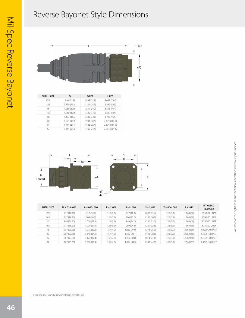
SHELL SIZE Q D REF. L REF.
10SL .898 (22.8) 0.898 (22.8) 3.087 (78.4)
14S 1.150 (29.2) 1.122 (28.5) 3.299 (83.8)
16 1.260 (32.0) 1.339 (34.0) 3.756 (95.4)
16S 1.260 (32.0) 1.339 (34.0) 3.500 (88.9)
18 1.437 (36.5) 1.339 (34.0) 3.799 (96.5)
20 1.571 (39.9) 1.594 (40.5) 4.445 (112.9)
22 1.697 (43.1) 1.594 (40.5) 4.445 (112.9)
24 1.835 (46.6) 1.791 (45.5) 4.445 (112.9)
SHELL SIZE M +.016-.000 A +.000-.006 P +/- .008 R +/- .004 S +/- .012 T +.004-.000 L + .012B THREAD CLASS 2A
10SL .717 (18.20) .717 (18.2) .110 (2.8) .717 (18.2) 1.000 (25.4) .126 (3.2) 1.969 (50) .6250-24 UNEF
14S .717 (18.20) .969 (24.6) .126 (3.2) .906 (23.0) 1.181 (30.0) .126 (3.2) 1.969 (50) .7500-20 UNEF
16 .846 (21.50) 1.079 (27.4) .126 (3.2) .969 (24.6) 1.280 (32.5) .126 (3.2) 2.362 (60) .8750-20 UNEF
16S .717 (18.20) 1.079 (27.4) .126 (3.2) .969 (24.6) 1.280 (32.5) .126 (3.2) 1.969 (50) .8750-20 UNEF
18 .907 (23.05) 1.213 (30.8) .157 (4.0) 1.063 (27.0) 1.378 (35.0) .126 (3.2) 2.362 (60) 1.0000-20 UNEF
20 .907 (23.05) 1.346 (34.2) .157 (4.0) 1.157 (29.4) 1.496 (38.0) .126 (3.2) 2.362 (60) 1.1875-18 UNEF
22 .907 (23.05) 1.472 (37.4) .157 (4.0) 1.252 (31.8) 1.614 (41.0) .126 (3.2) 2.362 (60) 1.1875-18 UNEF
24 .907 (23.05) 1.610 (40.9) .157 (4.0) 1.374 (34.9) 1.752 (44.5) .146 (3.7) 2.560 (65) 1.4375-18 UNEF
Mil-Spec Reverse Bayonet
46
We
rese
rve
the
right
to m
ake
tech
nica
l alte
ratio
ns w
ithou
t prio
r not
ice.
øA
L S
R
øT4x
R
SBThread
PM
øD
øQ
L
Reverse Bayonet Style Dimensions
We reserve the right to m
ake technical alterations without prior notice.
All dimensions in inches (millimeters in parenthesis)
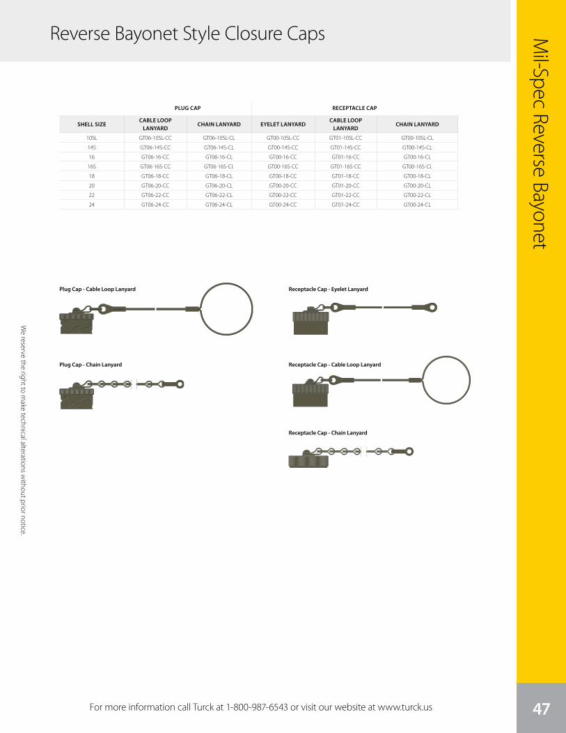
We
rese
rve
the
right
to m
ake
tech
nica
l alte
ratio
ns w
ithou
t prio
r not
ice.
Mil-Spec Reverse Bayonet
47
PLUG CAP RECEPTACLE CAP
SHELL SIZECABLE LOOP
LANYARDCHAIN LANYARD EYELET LANYARD
CABLE LOOP LANYARD
CHAIN LANYARD
10SL GT06-10SL-CC GT06-10SL-CL GT00-10SL-CC GT01-10SL-CC GT00-10SL-CL
14S GT06-14S-CC GT06-14S-CL GT00-14S-CC GT01-14S-CC GT00-14S-CL
16 GT06-16-CC GT06-16-CL GT00-16-CC GT01-16-CC GT00-16-CL
16S GT06-16S-CC GT06-16S-CL GT00-16S-CC GT01-16S-CC GT00-16S-CL
18 GT06-18-CC GT06-18-CL GT00-18-CC GT01-18-CC GT00-18-CL
20 GT06-20-CC GT06-20-CL GT00-20-CC GT01-20-CC GT00-20-CL
22 GT06-22-CC GT06-22-CL GT00-22-CC GT01-22-CC GT00-22-CL
24 GT06-24-CC GT06-24-CL GT00-24-CC GT01-24-CC GT00-24-CL
For more information call Turck at 1-800-987-6543 or visit our website at www.turck.us
We reserve the right to m
ake technical alterations without prior notice.
Plug Cap - Cable Loop Lanyard Receptacle Cap - Eyelet Lanyard
Receptacle Cap - Cable Loop Lanyard
Receptacle Cap - Chain Lanyard
Plug Cap - Chain Lanyard
Reverse Bayonet Style Closure Caps

Bulk CableProper cable selection is critical to product performance. Turck offers high quality cables with a wide variety of options to
ensure we can provide our customers with the optimal cable solution for their application challenges. Not only do we have
cable solutions for flexing, welding, and extreme temperatures, but we also have the capability of utilizing our internal cable
design team to create custom cables to fit specific application requirements.
Turck’s breadth of standard cable offerings provide UL approved solutions anywhere from 2 to 35 conductors and gauge sizes
between 8 to 28 AWG, along with multiple cable jacket material options. Additionally, there are many options for network media
cables as well as solutions with foil or braided shielding for RFI and EMI noise immunity.
Standard Cable Types:
• PVC
• TPU
• TPE
• Flexlife®-20
• Extremelife™
48
PVC Jacketed Cables (page 50)
Turck’s PVC (Polyvinyl Chloride) jacketed cables offer the most features and highest quality available in the
market while remaining a cost effective solution. These cables carry UL ITC and PLTC listings, are flame retardant
to FT4, oil resistant to UL I and II, resistant to many industrial chemicals and solvents, and are sunlight resistant.
While these cables are designed for high flex life, they are also flexible for ease of use and installation. Cables are
available with Exposed Run (ER) and Direct Burial (DB) listings, meaning they meet the same crush and impact
requirements as metal clad cables, but without the weight, size, or expense of metal.
TPU (page 62)
TPU (Thermoplastic Polyurethane) jacketed cables have long been considered the most cut-through and
abrasion resistant cables available. Turck offers cables with UL and CSA AWM recognition, -40 °C to + 90 °C
operating temperatures with an FT1 flame rating. TPU is highly resistant to oil and lubricants including cutting oils,
transmission fluids, and gasoline. These cables offer excellent flex life, and can also be made into retractile cords in
a wide variety of lengths and sizes.
TPE (page 66)
Turck’s TPE (Thermo-Plastic Elastomer) jacketed cables are robust and reliable in many demanding applications.
Very flexible for ease of use, these cables are also oil resistant to UL Oil Res I and II, UV resistant, and are resistant to
cut through and abrasion. Turck’s TPE jacket material also offers excellent resistance to weld slag buildup. Cables
carry UL ITC and PLTC listings and are available with Exposed Run (ER) and Direct Burial (DB) listings, meaning they
meet the same crush and impact requirements as metal clad cables, but without the weight, size, or expense of
metal.
Flexlife-20 (page 70)
Engineered for robotic, motion systems, and C-tracks, Turck’s Flexlife-20 cables are guaranteed* for 20 million flex
cycles whether the flexing is a tick-tock motion, torsional bend and flex, or in a C-Track. Available with Turck’s TPE
jacket material, they are oil resistant, weld spatter resistant and UV resistant.
(*when properly installed)
Extremelife (page 72)
Turck’s unique Extremelife-60 cable family is full featured and agency approved for even the harshest applications,
including oil and gas, agricultural equipment, construction equipment, or anywhere else extreme conditions
require extreme performance. These cables have earned many listings, including UL ITC, PLTC, TC, Exposed Run
(ER), Direct Burial (DB), and CSA CIC, CIC/TC. They remain flexible enough to work with at even -40 °C and carry UL
-60 °C cold bend and UL/CSA -40 °C cold impact listings. They also are FT 4 flame retardant, UL Oil Resistant I and
II, and UV resistant. No other cable family on the market can claim all of these features while also providing a cost
effective solution.
Types of Cable Mil-Spec Bulk Cable
49
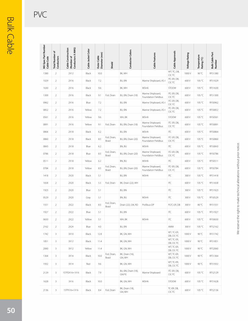
Mil-
Spec
Par
t Num
ber
Cabl
e Co
de
Tota
l Num
ber o
f Co
nduc
tors
Cabl
e Co
nstr
uctio
n (N
umbe
r of
Cond
ucto
rs X
AW
G)
Cabl
e Ja
cket
Col
or
Out
er C
able
D
iam
eter
(mm
)
Shie
ld
Cond
ucto
r Col
ors
Cabl
e Fe
atur
es
Cabl
e A
ppro
vals
Volta
ge R
atin
g
Tem
pera
ture
Ra
ting
(°C)
Bulk
Cab
le P
art
Num
ber
1380 2 2X12 Black 10.0 BK, WHWT, TC, DB, CIC-TC
1000 V 90 °C RF51380
1029 2 2X16 Black 7.2 BU, BN Marine Shipboard, AS-IITC-ER, DB, CIC-TC
600 V 105 °C RF51029
1630 2 2X16 Black 9.6 BK, WH MSHA STOOW 600 V 105 °C RF51630
1300 2 2X16 Black 9.1 Foil, Drain BU, BN, Drain (18)Marine Shipboard, Foundation Fieldbus
ITC-ER, DB, CIC-TC
600 V 105 °C RF51300
0962 2 2X16 Blue 7.2 BU, BN Marine Shipboard, AS-IITC-ER, DB, CIC-TC
600 V 105 °C RF50962
0852 2 2X16 Yellow 7.2 BU, BN Marine Shipboard, AS-IITC-ER, DB, CIC-TC
600 V 105 °C RF50852
0561 2 2X16 Yellow 9.6 WH, BK MSHA STOOW 600 V 105 °C RF50561
0891 2 2X16 Yellow 9.1 Foil, Drain BU, BN, Drain (18)Marine Shipboard, Foundation Fieldbus
ITC-ER, DB, CIC-TC
600 V 105 °C RF50891
0864 2 2X18 Black 6.2 BU, BN MSHA ITC 600 V 105 °C RF50864
0860 2 2X18 Black 8.5Foil, Drain, Braid
BU, BN, Drain (20)Marine Shipboard, Foundation Fieldbus
ITC-ER, DB, CIC-TC
600 V 105 °C RF50860
0843 2 2X18 Blue 6.2 BN, BU MSHA ITC 600 V 105 °C RF50843
0786 2 2X18 Blue 8.5Foil, Drain, Braid
BU, BN, Drain (20)Marine Shipboard, Foundation Fieldbus
ITC-ER, DB, CIC-TC
600 V 105 °C RF50786
0511 2 2X18 Yellow 6.2 BN, BU MSHA ITC 600 V 105 °C RF50511
0784 2 2X18 Yellow 8.5Foil, Drain, Braid
BU, BN, Drain (20)Marine Shipboard, Foundation Fieldbus
ITC-ER, DB, CIC-TC
600 V 105 °C RF50784
1418 2 2X20 Black 5.1 BU, BN MSHA ITC 300 V 105 °C RF51418
1658 2 2X20 Black 5.5 Foil, Drain BK, Drain (22), WH ITC 600 V 105 °C RF51658
1923 2 2X20 Blue 5.1 BU, BN ITC 300 V 105 °C RF51923
0529 2 2X20 Gray 5.1 BN, BU MSHA ITC 300 V 105 °C RF50529
1551 2 2X22 Black 8.5Foil, Drain, Braid
Drain (22), GN, RD Profibus-DP PLTC-ER, DB 300 V 80 °C RF51551
1927 2 2X22 Blue 5.1 BU, BN ITC 600 V 105 °C RF51927
0650 2 2X22 Yellow 5.1 WH, BK MSHA ITC 600 V 105 °C RF50650
2162 2 2X24 Blue 4.0 BU, BN AWM 300 V 105 °C RF52162
1742 3 3X10 Black 12.8 BK, GN, WHWT, TC-ER, DB, CIC-TC
1000 V 90 °C RF51742
1851 3 3X12 Black 11.4 BK, GN, WHWT, TC-ER, DB, CIC-TC
1000 V 90 °C RF51851
2060 3 3X12 Yellow 11.4 BK, GN, WHWT, TC-ER, DB, CIC-TC
1000 V 90 °C RF52060
1364 3 3X14 Black 10.0Foil, Drain, Braid
BK, Drain (16), GN, WH
WT, TC-ER, DB, CIC-TC
1000 V 90 °C RF51364
1932 3 3X14 Red 9.6 BK, GN, WHWT, TC-ER, DB, CIC-TC
1000 V 90 °C RF51932
2129 3 1STPDX16+1X16 Black 7.9BU, BN, Drain (18), GN/YE
Marine ShipboardITC-ER, DB, CIC-TC
600 V 105 °C RF52129
1628 3 3X16 Black 10.0 BK, GN, WH MSHA STOOW 600 V 105 °C RF51628
2136 3 1STPX16+1X16 Black 8.4 Foil, DrainBK, Drain (18), GN, WH
TC-ER, DB, CIC-TC
600 V 105 °C RF52136
Bulk Cable
50
PVC
We
rese
rve
the
right
to m
ake
tech
nica
l alte
ratio
ns w
ithou
t prio
r not
ice.
We reserve the right to m
ake technical alterations without prior notice.
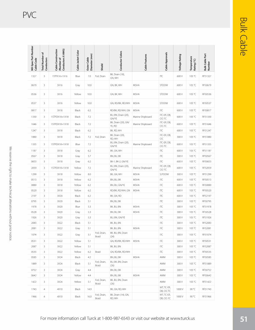
For more information call Turck at 1-800-987-6543 or visit our website at www.turck.us
PVC Bulk Cable
51
Mil-
Spec
Par
t Num
ber
Cabl
e Co
de
Tota
l Num
ber o
f Co
nduc
tors
Cabl
e Co
nstr
uctio
n (N
umbe
r of
Cond
ucto
rs X
AW
G)
Cabl
e Ja
cket
Col
or
Out
er C
able
D
iam
eter
(mm
)
Shie
ld
Cond
ucto
r Col
ors
Cabl
e Fe
atur
es
Cabl
e A
ppro
vals
Volta
ge R
atin
g
Tem
pera
ture
Ra
ting
(°C)
Bulk
Cab
le P
art
Num
ber
1327 3 1STPX16+1X16 Blue 7.0 Foil, DrainBK, Drain (18), GN, WH
ITC 600 V 105 °C RF51327
0679 3 3X16 Gray 10.0 GN, BK, WH MSHA STOOW 600 V 105 °C RF50679
0536 3 3X16 Yellow 10.0 GN, BK, WH MSHA STOOW 600 V 105 °C RF50536
0537 3 3X16 Yellow 10.0 GN, RD/BK, RD/WH MSHA STOOW 600 V 105 °C RF50537
0817 3 3X18 Black 6.2 RD/BK, RD/WH, GN MSHA ITC 600 V 105 °C RF50817
1330 3 1STPDX18+1X18 Black 7.2BU, BN, Drain (20), GN/YE
Marine ShipboardITC-ER, DB, CIC-TC
600 V 105 °C RF51330
1646 3 1STPDX18+1X18 Black 7.2BK, Drain (20), GN/YE, RD
Marine ShipboardITC-ER, DB, CIC-TC
600 V 105 °C RF51646
1247 3 3X18 Black 6.2 BK, RD, WH ITC 600 V 105 °C RF51247
1880 3 3X18 Black 7.2 Foil, DrainBK, Drain (20), RD, WH
ITC-ER, DB, CIC
300 V 105 °C RF51880
1335 3 1STPDX18+1X18 Blue 7.2BU, BN, Drain (20), GN/YE
Marine ShipboardITC-ER, DB, CIC-TC
600 V 105 °C RF51335
1187 3 3X18 Gray 6.2 BK, GN, WH ITC 600 V 105 °C RF51187
0567 3 3X18 Gray 5.7 BN, BU, BK ITC 300 V 105 °C RF50567
0653 3 3X18 Gray 6.2 BK-1, BK-2, GN/YE ITC 600 V 105 °C RF50653
2059 3 1STPDX18+1X18 Yellow 7.2BU, BN, Drain (20), GN/YE
Marine ShipboardITC-ER, DB, CIC-TC
600 V 105 °C RF52059
1299 3 3X18 Yellow 8.0 BK, GN, WH MSHA SJTOOW 300 V 105 °C RF51299
0513 3 3X18 Yellow 6.2 BN, BU, BK MSHA ITC 600 V 105 °C RF50513
0880 3 3X18 Yellow 6.2 BN, BU, GN/YE MSHA ITC 600 V 105 °C RF50880
0520 3 3X18 Yellow 6.2 RD/BK, RD/WH, GN MSHA ITC 600 V 105 °C RF50520
2197 3 3X20 Black 6.2 BK, GN, RD ITC 600 V 105 °C RF52197
0795 3 3X20 Black 5.1 BN, BU, BK ITC 300 V 105 °C RF50795
1978 3 3X20 Blue 5.3 BK, BU, BN MSHA ITC 300 V 105 °C RF51978
0528 3 3X20 Gray 5.3 BN, BU, BK MSHA ITC 300 V 105 °C RF50528
1926 3 3X20 Gray 5.3 BU, BN, GN/YE ITC 300 V 105 °C RF51926
2083 3 3X22 Black 5.1 BK, BU, BN ITC 300 V 105 °C RF52083
2081 3 3X22 Gray 5.1 BK, BU, BN MSHA ITC 300 V 105 °C RF52081
1074 3 3X22 Gray 5.1Foil, Drain, Braid
BK, BU, BN, Drain (24)
ITC 300 V 105 °C RF51074
0531 3 3X22 Yellow 5.1 GN, RD/BK, RD/WH MSHA ITC 300 V 105 °C RF50531
2087 3 3X22 Yellow 5.1 BK, BU, BN ITC 300 V 105 °C RF52087
0535 3 3X22 Yellow 6.2 Braid GN, RD/BK, RD/WH ITC 300 V 105 °C RF50535
0585 3 3X24 Black 4.2 BN, BU, BK MSHA AWM 300 V 105 °C RF50585
1889 3 3X24 Black 5.1Foil, Drain, Braid
BU, BK, BN, Drain (26)
AWM 300 V 105 °C RF51889
0752 3 3X24 Gray 4.4 BN, BU, BK AWM 300 V 105 °C RF50752
0642 3 3X24 Yellow 4.4 BN, BU, BK MSHA AWM 300 V 105 °C RF50642
1422 3 3X24 Yellow 5.1Foil, Drain, Braid
BK, BU, BN, Drain (26)
AWM 300 V 105 °C RF51422
1743 4 4X10 Black 14.9 BK, GN, RD, WHWT, TC-ER, DB, CIC-TC
1000 V 90 °C RF51743
1966 4 4X10 Black 16.0Foil, Drain, Braid
BK, Drain (14), GN, RD, WH
WT, TC-ER, DB, CIC-TC
1000 V 90 °C RF51966
We
rese
rve
the
right
to m
ake
tech
nica
l alte
ratio
ns w
ithou
t prio
r not
ice.
We reserve the right to m
ake technical alterations without prior notice.
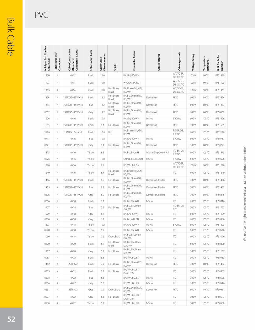
Bulk Cable
52
PVC
We
rese
rve
the
right
to m
ake
tech
nica
l alte
ratio
ns w
ithou
t prio
r not
ice.
Mil-
Spec
Par
t Num
ber
Cabl
e Co
de
Tota
l Num
ber o
f Co
nduc
tors
Cabl
e Co
nstr
uctio
n (N
umbe
r of
Cond
ucto
rs X
AW
G)
Cabl
e Ja
cket
Col
or
Out
er C
able
D
iam
eter
(mm
)
Shie
ld
Cond
ucto
r Col
ors
Cabl
e Fe
atur
es
Cabl
e A
ppro
vals
Volta
ge R
atin
g
Tem
pera
ture
Ra
ting
(°C)
Bulk
Cab
le P
art
Num
ber
1850 4 4X12 Black 12.6 BK, GN, RD, WHWT, TC-ER, DB, CIC-TC
1000 V 90 °C RF51850
1193 4 4X14 Black 10.0 WH, GN, BK, RDWT, TC-ER, DB, CIC-TC
1000 V 90 °C RF51193
1363 4 4X14 Black 10.8Foil, Drain, Braid
BK, Drain (16), GN, RD, WH
WT, TC-ER, DB, CIC-TC
1000 V 90 °C RF51363
1454 4 1STPX15+1STPX18 Black 11.2Foil, Drain, Braid
BK, BU, Drain (18), RD, WH
DeviceNet PLTC 600 V 80 °C RF51454
1453 4 1STPX15+1STPX18 Blue 11.2Foil, Drain, Braid
BK, BU, Drain (18), RD, WH
DeviceNet PLTC 600 V 80 °C RF51453
0652 4 1STPX15+1STPX18 Gray 11.2Foil, Drain, Braid
BK, BU, Drain (18), RD, WH
DeviceNet PLTC 600 V 80 °C RF50652
1626 4 4X16 Black 10.8 BK, GN, RD, WH MSHA STOOW 600 V 105 °C RF51626
1655 4 1STPX16+1STPX20 Black 8.4 Foil, DrainBK, BU, Drain (20), RD, WH
DeviceNet PLTC 300 V 80 °C RF51655
2139 4 1STRDX16+1X16 Black 10.8 FoilBK, Drain (18), GN, RD, WH
TC-ER, DB, CIC-TC
600 V 105 °C RF52139
0717 4 4X16 Blue 10.8 BK, GN, RD, WH MSHA STOOW 600 V 105 °C RF50717
0721 4 1STPX16+1STPX20 Gray 8.4 Foil, DrainBK, BU, Drain (20), RD, WH
DeviceNet PLTC 300 V 80 °C RF50721
1875 4 4X16 Yellow 8.5 BK, BU, BN, WH Marine Shipboard, AS-IITC-ER, DB, CIC-TC
600 V 105 °C RF51875
0626 4 4X16 Yellow 10.8 GN/YE, BU, BN, WH MSHA STOOW 600 V 105 °C RF50626
1220 4 4X16 Yellow 9.1 RD, WH, BK, GNWT, TC-ER, DB, CIC-TC
1000 V 90 °C RF51220
1249 4 4X16 Yellow 8.4Foil, Drain, Braid
BK, Drain (18), GN, RD, WH
ITC 600 V 105 °C RF51249
1456 4 1STPX17+1STPX20 Black 8.9 Foil, DrainBK, BU, Drain (20), RD, WH
DeviceNet, Flexlife PLTC 300 V 80 °C RF51456
1455 4 1STPX17+1STPX20 Blue 8.9 Foil, DrainBK, BU, Drain (20), RD, WH
DeviceNet, Flexlife PLTC 300 V 80 °C RF51455
0876 4 1STPX17+1STPX20 Gray 8.9 Foil, DrainBK, BU, Drain (20), RD, WH
DeviceNet, Flexlife PLTC 300 V 80 °C RF50876
0816 4 4X18 Black 6.7 BK, BU, BN, WH MSHA ITC 600 V 105 °C RF50816
1727 4 4X18 Blue 7.2 Foil, DrainBK, BU, BN, Drain (20), WH
ITC-ER, DB, CIC
300 V 105 °C RF51727
1929 4 4X18 Gray 6.7 BK, GN, RD, WH MSHA ITC 600 V 105 °C RF51929
0580 4 4X18 Gray 6.7 BK, BU, WH, BN MSHA ITC 600 V 105 °C RF50580
1693 4 4X18 Yellow 10.2 BK, GN, RD, WH MSHA STOOW 600 V 105 °C RF51693
0548 4 4X18 Yellow 6.7 BK, BU, BN, WH MSHA ITC 600 V 105 °C RF50548
1096 4 4X18 Yellow 7.2 Drain, BraidBK, BU, BN, Drain (20), WH
ITC 600 V 105 °C RF51096
0820 4 4X20 Black 6.7Foil, Drain, Braid
BK, BU, BN, Drain (22), WH
ITC 600 V 105 °C RF50820
1167 4 4X20 Gray 5.9 Foil, DrainBK, BU, BN, Drain (22), WH
ITC 300 V 105 °C RF51167
0983 4 4X22 Black 5.3 BN, WH, BU, BK MSHA ITC 300 V 105 °C RF50983
1452 4 2STPX22 Black 7.2 Foil, DrainBK, BU, Drain (22), RD, WH
DeviceNet PLTC 300 V 80 °C RF51452
0805 4 4X22 Black 5.3 Foil, DrainBN, WH, BU, BK, Drain (22)
ITC 300 V 105 °C RF50805
0598 4 4X22 Blue 5.3 BN, WH, BU, BK MSHA ITC 300 V 105 °C RF50598
0516 4 4X22 Gray 5.3 BN, WH, BU, BK MSHA ITC 300 V 105 °C RF50516
0651 4 2STPX22 Gray 7.9 Drain, BraidBK, BU, Drain (22), RD, WH
DeviceNet PLTC 600 V 80 °C RF50651
0577 4 4X22 Gray 5.3 Foil, DrainBN, WH, BU, BK, Drain (22)
ITC 300 V 105 °C RF50577
0530 4 4X22 Yellow 5.3 BN, WH, BU, BK MSHA ITC 300 V 105 °C RF50530
We reserve the right to m
ake technical alterations without prior notice.
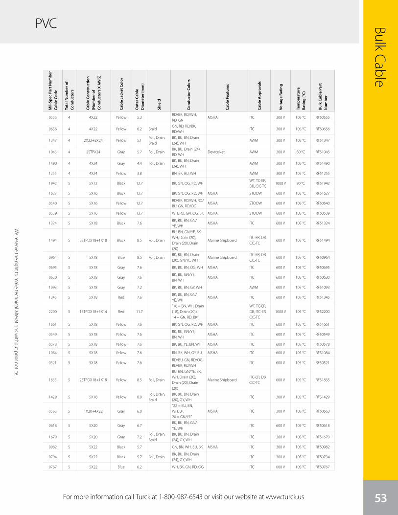
We
rese
rve
the
right
to m
ake
tech
nica
l alte
ratio
ns w
ithou
t prio
r not
ice.
PVC Bulk Cable
53For more information call Turck at 1-800-987-6543 or visit our website at www.turck.us
We reserve the right to m
ake technical alterations without prior notice.
Mil-
Spec
Par
t Num
ber
Cabl
e Co
de
Tota
l Num
ber o
f Co
nduc
tors
Cabl
e Co
nstr
uctio
n (N
umbe
r of
Cond
ucto
rs X
AW
G)
Cabl
e Ja
cket
Col
or
Out
er C
able
D
iam
eter
(mm
)
Shie
ld
Cond
ucto
r Col
ors
Cabl
e Fe
atur
es
Cabl
e A
ppro
vals
Volta
ge R
atin
g
Tem
pera
ture
Ra
ting
(°C)
Bulk
Cab
le P
art
Num
ber
0555 4 4X22 Yellow 5.3RD/BK, RD/WH, RD, GN
MSHA ITC 300 V 105 °C RF50555
0656 4 4X22 Yellow 6.2 BraidGN, RD, RD/BK, RD/WH
ITC 300 V 105 °C RF50656
1347 4 2X22+2X24 Yellow 5.1Foil, Drain, Braid
BK, BU, BN, Drain (24), WH
AWM 300 V 105 °C RF51347
1045 4 2STPX24 Gray 5.7 Foil, DrainBK, BU, Drain (24), RD, WH
DeviceNet AWM 300 V 80 °C RF51045
1490 4 4X24 Gray 4.4 Foil, DrainBK, BU, BN, Drain (24), WH
AWM 300 V 105 °C RF51490
1255 4 4X24 Yellow 3.8 BN, BK, BU, WH AWM 300 V 105 °C RF51255
1942 5 5X12 Black 12.7 BK, GN, OG, RD, WHWT, TC-ER, DB, CIC-TC
1000 V 90 °C RF51942
1627 5 5X16 Black 12.7 BK, GN, OG, RD, WH MSHA STOOW 600 V 105 °C RF51627
0540 5 5X16 Yellow 12.7RD/BK, RD/WH, RD/BU, GN, RD/OG
MSHA STOOW 600 V 105 °C RF50540
0539 5 5X16 Yellow 12.7 WH, RD, GN, OG, BK MSHA STOOW 600 V 105 °C RF50539
1324 5 5X18 Black 7.6BK, BU, BN, GN/YE, WH
MSHA ITC 600 V 105 °C RF51324
1494 5 2STPDX18+1X18 Black 8.5 Foil, Drain
BU, BN, GN/YE, BK, WH, Drain (20), Drain (20), Drain (20)
Marine ShipboardITC-ER, DB, CIC-TC
600 V 105 °C RF51494
0964 5 5X18 Blue 8.5 Foil, DrainBK, BU, BN, Drain (20), GN/YE, WH
Marine ShipboardITC-ER, DB, CIC-TC
600 V 105 °C RF50964
0695 5 5X18 Gray 7.6 BK, BU, BN, OG, WH MSHA ITC 600 V 105 °C RF50695
0630 5 5X18 Gray 7.6BK, BU, GN/YE, BN, WH
MSHA ITC 600 V 105 °C RF50630
1093 5 5X18 Gray 7.2 BK, BU, BN, GY, WH AWM 600 V 105 °C RF51093
1345 5 5X18 Red 7.6BK, BU, BN, GN/YE, WH
MSHA ITC 600 V 105 °C RF51345
2200 5 1STPDX18+3X14 Red 11.7"18 = BN, WH, Drain (18), Drain (20)z14 = GN, RD, BK”
WT, TC-ER, DB, ITC-ER, CIC-TC
1000 V 105 °C RF52200
1661 5 5X18 Yellow 7.6 BK, GN, OG, RD, WH MSHA ITC 600 V 105 °C RF51661
0549 5 5X18 Yellow 7.6BK, BU, GN/YE, BN, WH
MSHA ITC 600 V 105 °C RF50549
0578 5 5X18 Yellow 7.6 BK, BU, YE, BN, WH MSHA ITC 600 V 105 °C RF50578
1084 5 5X18 Yellow 7.6 BN, BK, WH, GY, BU MSHA ITC 600 V 105 °C RF51084
0521 5 5X18 Yellow 7.6RD/BU, GN, RD/OG, RD/BK, RD/WH
ITC 600 V 105 °C RF50521
1835 5 2STPDX18+1X18 Yellow 8.5 Foil, Drain
BU, BN, GN/YE, BK, WH, Drain (20), Drain (20), Drain (20)
Marine ShipboardITC-ER, DB, CIC-TC
600 V 105 °C RF51835
1429 5 5X18 Yellow 8.0Foil, Drain, Braid
BK, BU, BN, Drain (20), GY, WH
ITC 300 V 105 °C RF51429
0563 5 1X20+4X22 Gray 6.0"22 = BU, BN, WH, BK 20 = GN/YE”
MSHA ITC 300 V 105 °C RF50563
0618 5 5X20 Gray 6.7BK, BU, BN, GN/YE, WH
ITC 600 V 105 °C RF50618
1679 5 5X20 Gray 7.2Foil, Drain, Braid
BK, BU, BN, Drain (24), GY, WH
ITC 300 V 105 °C RF51679
0982 5 5X22 Black 5.7 GN, BN, WH, BU, BK MSHA ITC 300 V 105 °C RF50982
0794 5 5X22 Black 5.7 Foil, DrainBK, BU, BN, Drain (24), GY, WH
ITC 300 V 105 °C RF50794
0767 5 5X22 Blue 6.2 WH, BK, GN, RD, OG ITC 600 V 105 °C RF50767

PVCBulk Cable
54
We
rese
rve
the
right
to m
ake
tech
nica
l alte
ratio
ns w
ithou
t prio
r not
ice.
Mil-
Spec
Par
t Num
ber
Cabl
e Co
de
Tota
l Num
ber o
f Co
nduc
tors
Cabl
e Co
nstr
uctio
n (N
umbe
r of
Cond
ucto
rs X
AW
G)
Cabl
e Ja
cket
Col
or
Out
er C
able
D
iam
eter
(mm
)
Shie
ld
Cond
ucto
r Col
ors
Cabl
e Fe
atur
es
Cabl
e A
ppro
vals
Volta
ge R
atin
g
Tem
pera
ture
Ra
ting
(°C)
Bulk
Cab
le P
art
Num
ber
0543 5 5X22 Gray 5.7 GY, BN, WH, BU, BK MSHA ITC 300 V 105 °C RF50543
1967 5 2STPDX22+1X22 Gray 8.5 Foil, DrainBU, WH, BK, RD, Drain (22), Drain (22)
CAN AWM 300 V 80 °C RF51967
0713 5 5X22 Gray 6.6Foil, Drain, Braid
BN, WH, BU, BK, GY, Drain (24)
ITC 600 V 105 °C RF50713
0684 5 5X22 Yellow 5.7 BN, WH, GY, BK, BU MSHA ITC 300 V 105 °C RF50684
0556 5 5X22 Yellow 5.7RD/BK, RD/WH, RD, GN, RD/YE
MSHA ITC 300 V 105 °C RF50556
0756 5 2UTPX22+1X22 Yellow 7.2Foil, Drain, Braid
BK, BU, BN, Drain (24), GY, WH
ITC 300 V 105 °C RF50756
1905 5 5X24 Gray 4.8Foil, Drain, Braid
BN, WH, BU, BK, GY, Drain (26)
AWM 300 V 105 °C RF51905
1823 5 5X24 Yellow 4.5 BK, BU, BN, GY, WH AWM 300 V 105 °C RF51823
1884 6 4X8+2X14 Black 27.6
"14 = BU/YEL (-), BU/YE (+) 8 = BK V, BK U, GN/YE, BK W”
WT, TC-ER, STOOW, CIC-TC
1000 V 90 °C RF51884
2072 6 4X12+2X14 Black 20.1
"14 = BU/YE (-), BU/YE (+) 12 = BK V, BK U, GN/YE, BK W”
WT, TC-ER, STOOW, CIC-TC
1000 V 90 °C RF52072
1078 6 6X14 Yellow 12.0WH, RD, GN, OG, BK, BU
ITC 600 V 105 °C RF51078
1736 6 4X16+1STPDX20 Black 9.6Foil, Drain, Braid
BK, BU, Drain (20), GN, LightBU, LightBU/WH, RD
ITC 600 V 105 °C RF51736
1909 6 6X16 Blue 10.0BK, BU, GN, OG, RD, WH
Marine ShipboardITC-ER, DB, CIC-TC
600 V 105 °C RF51909
1329 6 6X16 Blue 9.6 Foil, DrainBK, BU, Drain (18), GN, OG, RD, WH
ITC 600 V 105 °C RF51329
1030 6 6X16 Yellow 9.0GN, BK, WH, RD, OG, BU
ITC 600 V 105 °C RF51030
1535 6 6X16 Yellow 9.8Foil, Drain, Braid
BK, BU, Drain (18), GN, OG, RD, WH
ITC 600 V 105 °C RF51535
1600 6 1STPDX18+4X16 Black 12.5BK, BU, Drain (18), GN, OG, RD, WH
Marine Shipboard, CANITC-ER, DB, CIC-TC
600 V 105 °C RF51600
1641 6 6X18 Black 8.4BU, BN, GY, GN, WH, YE
MSHA ITC 600 V 105 °C RF51641
0551 6 6X18 Black 8.4 Foil, DrainBU, WH, BK, GN, RD, OG, Drain (20)
MSHA ITC 600 V 105 °C RF50551
2009 6 3STPX18 Black 9.8 Foil, DrainBK/WH, BU/WH, BN/WH, Drain (20), WH/BK, WH/BU, WH/BN
ITC-ER, DB, CIC-TC
600 V 105 °C RF52009
1588 6 6X18 Blue 8.4 Foil, DrainBK, BU, Drain (20), GN, OG, RD, WH
MSHA ITC 600 V 105 °C RF51588
1662 6 6X18 Yellow 8.4BK, BU, GN, OG, RD, WH
MSHA ITC 600 V 105 °C RF51662
1085 6 6X18 Yellow 8.4BN, WH, BU, BK, GY, PK
ITC 600 V 105 °C RF51085
0575 6 6X18 Yellow 8.4WH, GN, YE, GY, BN, BU
ITC 600 V 105 °C RF50575
1430 6 6X18 Yellow 7.6Foil, Drain, Braid
BK, BU, BN, Drain (20), GY, PK, WH
ITC 300 V 105 °C RF51430
1735 6 1STPDX20+4X12 Black 11.3Foil, Drain, Braid
"12 = GN, RD, BU, BK, Drain (16) 20 = LT BU/WH, LT BU, Drain (22)”
AWM 600 V 105 °C RF51735
0640 6 6X20 Gray 6.7BK, BU, GN, OG, RD, WH
MSHA ITC 300 V 105 °C RF50640
We reserve the right to m
ake technical alterations without prior notice.
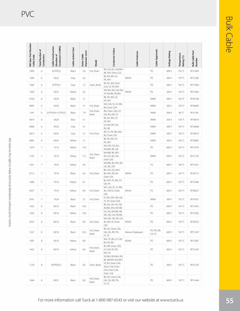
We
rese
rve
the
right
to m
ake
tech
nica
l alte
ratio
ns w
ithou
t prio
r not
ice.
Bulk Cable
55
PVC
For more information call Turck at 1-800-987-6543 or visit our website at www.turck.us
We reserve the right to m
ake technical alterations without prior notice.
Mil-
Spec
Par
t Num
ber
Cabl
e Co
de
Tota
l Num
ber o
f Co
nduc
tors
Cabl
e Co
nstr
uctio
n (N
umbe
r of
Cond
ucto
rs X
AW
G)
Cabl
e Ja
cket
Col
or
Out
er C
able
D
iam
eter
(mm
)
Shie
ld
Cond
ucto
r Col
ors
Cabl
e Fe
atur
es
Cabl
e A
ppro
vals
Volta
ge R
atin
g
Tem
pera
ture
Ra
ting
(°C)
Bulk
Cab
le P
art
Num
ber
1809 6 3UTPX22 Black 9.6 Foil, DrainRD, GN, BU, GN/WH, BK, WH, Drain (22)
ITC 600 V 105 °C RF51809
1284 6 6X22 Gray 6.2BK, BU, BN, GY, PK, WH
MSHA ITC 300 V 105 °C RF51284
1964 6 3STPX22 Gray 7.2 Drain, BraidBK, BU, BN, Drain (24), GY, PK, WH
ITC 300 V 105 °C RF51964
1003 6 6X22 Yellow 6.2RD/WH, RD, GN, RD/YE, RD/BK, RD/BU
MSHA ITC 300 V 105 °C RF51003
0758 6 6X24 Black 5.1BK, BU, BN, GY, PK, WH
AWM 300 V 105 °C RF50758
0845 6 6X24 Black 5.1 Foil, DrainWH, GN, YE, GY, BN, BU, Drain (24)
AWM 300 V 105 °C RF50845
1341 6 2UTPX24+1UTPX22 Black 7.9Foil, Drain, Braid
BN, Drain (26), GY, GN, RD, WH, YE
AWM 300 V 80 °C RF51341
0619 6 6X24 Blue 5.1BK, BU, BN, GY, PK, WH
AWM 300 V 105 °C RF50619
0608 6 6X24 Gray 5.1GY, BN, WH, PK, BU, BK
AWM 300 V 105 °C RF50608
0610 6 6X24 Gray 5.1 Foil, DrainBK, GY, PK, BN, WH, BU, Drain (24)
AWM 300 V 105 °C RF50610
0885 6 6X24 Yellow 5.1BK, BU, BN, GY, PK, WH
AWM 300 V 105 °C RF50885
1079 7 7X14 Yellow 12.0WH, RD, OG, BU, WH/BK, BK, GN
ITC 600 V 105 °C RF51079
1192 7 7X14 Yellow 11.2Foil, Drain, Braid
WH/BK, BK, WH, RD, OG, BU, GN, Drain (20)
AWM 600 V 105 °C RF51192
1031 7 7X16 Yellow 9.6WH/BK, BK, WH, RD, OG, BU, GN
ITC 600 V 105 °C RF51031
0715 7 7X18 Black 8.4 Foil, DrainBK, GN, OG, WH/BK, WH, RD, BU, Drain (20)
MSHA ITC 600 V 105 °C RF50715
1086 7 7X18 Yellow 8.1BU, WH, YE, BN, GY, GN, PK
ITC 600 V 105 °C RF51086
0637 7 7X18 Yellow 8.4 Foil, DrainWH, GN, YE, GY, BN, BU, GN/YE, Drain (20)
MSHA ITC 600 V 105 °C RF50637
0761 7 7X24 Black 5.1 Foil, DrainGY, BU, WH, BN, GN, YE, PK, Drain (24)
AWM 300 V 105 °C RF50761
1625 8 8X16 Black 10.0BK, BU, GN, OG, RD, RD/BK, WH, WH/BK
ITC 600 V 105 °C RF51625
1032 8 8X16 Yellow 10.0OG, BU, WH/BK, BK, WH, RD, GN, RD/BK
ITC 600 V 105 °C RF51032
0552 8 8X18 Black 8.9 Foil, DrainWH, BK, GN, RD, OG, BU, BN, YE, Drain (20)
MSHA ITC 600 V 105 °C RF50552
1547 8 8X18 Black 10.5Foil, Drain, Braid
BK, BU, Drain (20), GN, OG, RD, TN, VT, YE
Marine ShipboardITC-ER, DB, CIC-TC
600 V 105 °C RF51547
1087 8 8X18 Yellow 8.9WH, YE, BN, GY, GN, BU, PK, RD
MSHA ITC 600 V 105 °C RF51087
1432 8 8X18 Yellow 9.6Foil, Drain, Braid
BU, BN, Drain (20), GY, GN, PK, RD, WH, YE
ITC 600 V 105 °C RF51432
1276 8 4STPDX22 Black 8.5 Drain, Braid
YE/WH, RD/WH, RD, BK, BK/WH, BU/WH, YE, BU, Drain (24), Drain (24), Drain (24), Drain (24), Drain (24)
ITC 300 V 105 °C RF51276
1644 8 8X22 Black 8.0Foil, Drain, Braid
BK, BU, Drain (24), GN, OG, RD, TN, VT, YE
ITC 600 V 105 °C RF51644
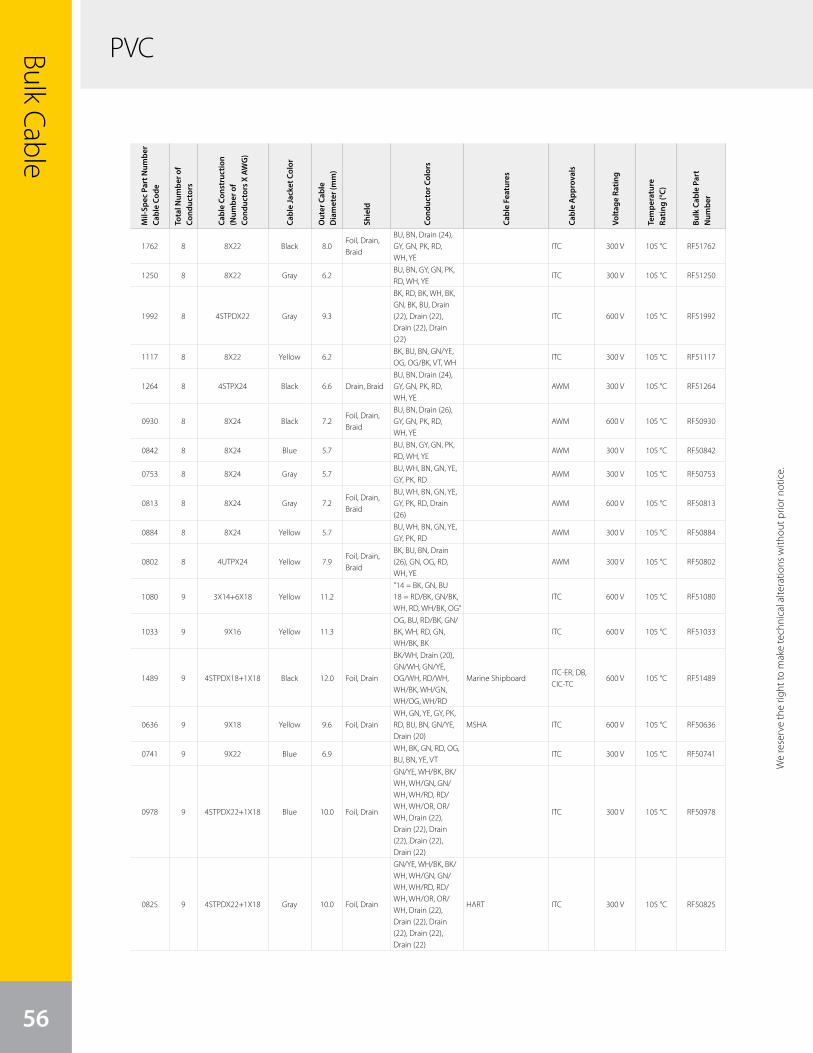
PVCBulk Cable
56
We
rese
rve
the
right
to m
ake
tech
nica
l alte
ratio
ns w
ithou
t prio
r not
ice.
Mil-
Spec
Par
t Num
ber
Cabl
e Co
de
Tota
l Num
ber o
f Co
nduc
tors
Cabl
e Co
nstr
uctio
n (N
umbe
r of
Cond
ucto
rs X
AW
G)
Cabl
e Ja
cket
Col
or
Out
er C
able
D
iam
eter
(mm
)
Shie
ld
Cond
ucto
r Col
ors
Cabl
e Fe
atur
es
Cabl
e A
ppro
vals
Volta
ge R
atin
g
Tem
pera
ture
Ra
ting
(°C)
Bulk
Cab
le P
art
Num
ber
1762 8 8X22 Black 8.0Foil, Drain, Braid
BU, BN, Drain (24), GY, GN, PK, RD, WH, YE
ITC 300 V 105 °C RF51762
1250 8 8X22 Gray 6.2BU, BN, GY, GN, PK, RD, WH, YE
ITC 300 V 105 °C RF51250
1992 8 4STPDX22 Gray 9.3
BK, RD, BK, WH, BK, GN, BK, BU, Drain (22), Drain (22), Drain (22), Drain (22)
ITC 600 V 105 °C RF51992
1117 8 8X22 Yellow 6.2BK, BU, BN, GN/YE, OG, OG/BK, VT, WH
ITC 300 V 105 °C RF51117
1264 8 4STPX24 Black 6.6 Drain, BraidBU, BN, Drain (24), GY, GN, PK, RD, WH, YE
AWM 300 V 105 °C RF51264
0930 8 8X24 Black 7.2Foil, Drain, Braid
BU, BN, Drain (26), GY, GN, PK, RD, WH, YE
AWM 600 V 105 °C RF50930
0842 8 8X24 Blue 5.7BU, BN, GY, GN, PK, RD, WH, YE
AWM 300 V 105 °C RF50842
0753 8 8X24 Gray 5.7BU, WH, BN, GN, YE, GY, PK, RD
AWM 300 V 105 °C RF50753
0813 8 8X24 Gray 7.2Foil, Drain, Braid
BU, WH, BN, GN, YE, GY, PK, RD, Drain (26)
AWM 600 V 105 °C RF50813
0884 8 8X24 Yellow 5.7BU, WH, BN, GN, YE, GY, PK, RD
AWM 300 V 105 °C RF50884
0802 8 4UTPX24 Yellow 7.9Foil, Drain, Braid
BK, BU, BN, Drain (26), GN, OG, RD, WH, YE
AWM 300 V 105 °C RF50802
1080 9 3X14+6X18 Yellow 11.2"14 = BK, GN, BU 18 = RD/BK, GN/BK, WH, RD, WH/BK, OG”
ITC 600 V 105 °C RF51080
1033 9 9X16 Yellow 11.3OG, BU, RD/BK, GN/BK, WH, RD, GN, WH/BK, BK
ITC 600 V 105 °C RF51033
1489 9 4STPDX18+1X18 Black 12.0 Foil, Drain
BK/WH, Drain (20), GN/WH, GN/YE, OG/WH, RD/WH, WH/BK, WH/GN, WH/OG, WH/RD
Marine ShipboardITC-ER, DB, CIC-TC
600 V 105 °C RF51489
0636 9 9X18 Yellow 9.6 Foil, DrainWH, GN, YE, GY, PK, RD, BU, BN, GN/YE, Drain (20)
MSHA ITC 600 V 105 °C RF50636
0741 9 9X22 Blue 6.9WH, BK, GN, RD, OG, BU, BN, YE, VT
ITC 300 V 105 °C RF50741
0978 9 4STPDX22+1X18 Blue 10.0 Foil, Drain
GN/YE, WH/BK, BK/WH, WH/GN, GN/WH, WH/RD, RD/WH, WH/OR, OR/WH, Drain (22), Drain (22), Drain (22), Drain (22), Drain (22)
ITC 300 V 105 °C RF50978
0825 9 4STPDX22+1X18 Gray 10.0 Foil, Drain
GN/YE, WH/BK, BK/WH, WH/GN, GN/WH, WH/RD, RD/WH, WH/OR, OR/WH, Drain (22), Drain (22), Drain (22), Drain (22), Drain (22)
HART ITC 300 V 105 °C RF50825
We reserve the right to m
ake technical alterations without prior notice.
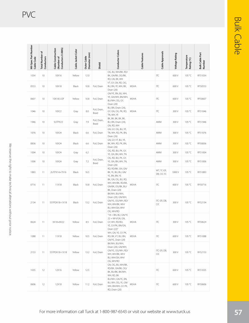
We
rese
rve
the
right
to m
ake
tech
nica
l alte
ratio
ns w
ithou
t prio
r not
ice.
Bulk Cable
57
PVC
For more information call Turck at 1-800-987-6543 or visit our website at www.turck.us
We reserve the right to m
ake technical alterations without prior notice.
Mil-
Spec
Par
t Num
ber
Cabl
e Co
de
Tota
l Num
ber o
f Co
nduc
tors
Cabl
e Co
nstr
uctio
n (N
umbe
r of
Cond
ucto
rs X
AW
G)
Cabl
e Ja
cket
Col
or
Out
er C
able
D
iam
eter
(mm
)
Shie
ld
Cond
ucto
r Col
ors
Cabl
e Fe
atur
es
Cabl
e A
ppro
vals
Volta
ge R
atin
g
Tem
pera
ture
Ra
ting
(°C)
Bulk
Cab
le P
art
Num
ber
1034 10 10X16 Yellow 12.0OG, BU, WH/BK, RD/BK, GN/BK, OG/BK, RD, GN, BK, WH
ITC 600 V 105 °C RF51034
0553 10 10X18 Black 10.8 Foil, DrainVT, GY, GN, RD, OG, BU, BN, YE, WH, BK, Drain (20)
MSHA ITC 600 V 105 °C RF50553
0607 10 10X18.S-DF Yellow 10.8 Foil, Drain
GN/YE, BN, BU, WH, YE, GN/WH, BN/WH, BU/WH, OG, GY, Drain (20)
MSHA ITC 600 V 105 °C RF50607
1046 10 10X22 Gray 8.0Foil, Drain, Braid
BU, BN, Drain (24), GY, GN, OG, PK, RD, TN, WH, YE
MSHA ITC 300 V 105 °C RF51046
1946 10 5UTPX22 Gray 7.9Foil, Drain, Braid
BK, BK, BK, BK, BK, BU, BN, Drain (24), GN, RD, WH
AWM 300 V 105 °C RF51946
1076 10 10X24 Black 6.6 Foil, DrainGN, GY, OG, BU, YE, TN, WH, RD, PK, BN, Drain (26)
AWM 300 V 105 °C RF51076
0836 10 10X24 Black 6.6 Foil, DrainGN, GY, VT, BU, YE, BK, WH, RD, PK, BN, Drain (26)
AWM 300 V 105 °C RF50836
1004 10 10X24 Gray 6.2OG, RD, BU, PK, GY, YE, GN, BN, WH, TN
AWM 300 V 105 °C RF51004
1006 10 10X24 Gray 7.2Foil, Drain, Braid
OG, RD, BU, PK, GY, YE, GN, BN, WH, TN, Drain (26)
AWM 300 V 105 °C RF51006
1883 11 2UTPX14+7X16 Black 16.5RD, RD/BK, GN, GN/BK, YE, BU, BU, GN/YE, BN, BN, YE
WT, TC-ER, DB, CIC-TC
1000 V 105 °C RF51883
0716 11 11X18 Black 10.8 Foil, Drain
BK, GN, OG, BU, RD, WH, WH/BK, RD/BK, GN/BK, OG/BK, BU/BK, Drain (20)
MSHA ITC 600 V 105 °C RF50716
2134 11 5STPDX18+1X18 Black 13.2 Foil, Drain
BK/WH, BU/WH, Drain (20), GN/WH, GN/YE, OG/WH, RD/WH, WH/BK, WH/BU, WH/GN, WH/OG, WH/RD
ITC-ER, DB, CIC
300 V 105 °C RF52134
0624 11 3X18+8X22 Yellow 8.5 Foil, Drain
"18 = BN, BU, GN/YE 22 = WH/GN, GN, GY, WH, RD/BU, YE, GY/PK, BN/GN, Drain (22)”
MSHA ITC 300 V 105 °C RF50624
1088 11 11X18 Yellow 10.5 Foil, DrainWH, GN, YE, GY, PK, RD, BK, VT, BU, BN, GN/YE, Drain (20)
MSHA ITC 600 V 105 °C RF51088
2153 11 5STPDX18+1X18 Yellow 13.2 Foil, Drain
BK/WH, BU/WH, Drain (20), GN/WH, GN/YE, OG/WH, RD/WH, WH/BK, WH/BU, WH/GN, WH/OG, WH/RD
ITC-ER, DB, CIC
300 V 105 °C RF52153
1035 12 12X16 Yellow 12.5
GN, OG, BU, WH/BK, RD/BK, GN/BK, OG/BK, BU/BK, BK/WH, WH, RD, BK
ITC 600 V 105 °C RF51035
0606 12 12X18 Yellow 11.2 Foil, Drain
BU/WH, GN/YE, BN, BU, WH, OG, YE, GN/WH, BN/WH, GY, PK, RD, Drain (20)
MSHA ITC 600 V 105 °C RF50606
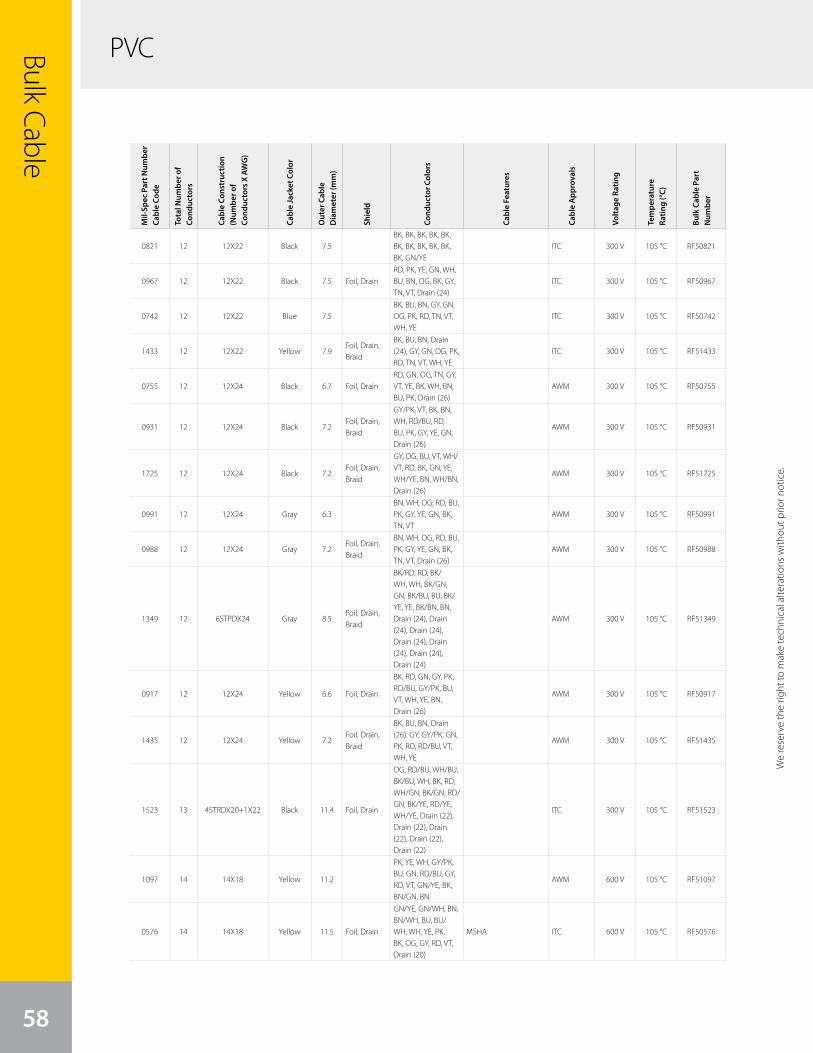
PVCBulk Cable
58
We
rese
rve
the
right
to m
ake
tech
nica
l alte
ratio
ns w
ithou
t prio
r not
ice.
Mil-
Spec
Par
t Num
ber
Cabl
e Co
de
Tota
l Num
ber o
f Co
nduc
tors
Cabl
e Co
nstr
uctio
n (N
umbe
r of
Cond
ucto
rs X
AW
G)
Cabl
e Ja
cket
Col
or
Out
er C
able
D
iam
eter
(mm
)
Shie
ld
Cond
ucto
r Col
ors
Cabl
e Fe
atur
es
Cabl
e A
ppro
vals
Volta
ge R
atin
g
Tem
pera
ture
Ra
ting
(°C)
Bulk
Cab
le P
art
Num
ber
0821 12 12X22 Black 7.5BK, BK, BK, BK, BK, BK, BK, BK, BK, BK, BK, GN/YE
ITC 300 V 105 °C RF50821
0967 12 12X22 Black 7.5 Foil, DrainRD, PK, YE, GN, WH, BU, BN, OG, BK, GY, TN, VT, Drain (24)
ITC 300 V 105 °C RF50967
0742 12 12X22 Blue 7.5BK, BU, BN, GY, GN, OG, PK, RD, TN, VT, WH, YE
ITC 300 V 105 °C RF50742
1433 12 12X22 Yellow 7.9Foil, Drain, Braid
BK, BU, BN, Drain (24), GY, GN, OG, PK, RD, TN, VT, WH, YE
ITC 300 V 105 °C RF51433
0755 12 12X24 Black 6.7 Foil, DrainRD, GN, OG, TN, GY, VT, YE, BK, WH, BN, BU, PK, Drain (26)
AWM 300 V 105 °C RF50755
0931 12 12X24 Black 7.2Foil, Drain, Braid
GY/PK, VT, BK, BN, WH, RD/BU, RD, BU, PK, GY, YE, GN, Drain (26)
AWM 300 V 105 °C RF50931
1725 12 12X24 Black 7.2Foil, Drain, Braid
GY, OG, BU, VT, WH/VT, RD, BK, GN, YE, WH/YE, BN, WH/BN, Drain (26)
AWM 300 V 105 °C RF51725
0991 12 12X24 Gray 6.3BN, WH, OG, RD, BU, PK, GY, YE, GN, BK, TN, VT
AWM 300 V 105 °C RF50991
0988 12 12X24 Gray 7.2Foil, Drain, Braid
BN, WH, OG, RD, BU, PK, GY, YE, GN, BK, TN, VT, Drain (26)
AWM 300 V 105 °C RF50988
1349 12 6STPDX24 Gray 8.5Foil, Drain, Braid
BK/RD, RD, BK/WH, WH, BK/GN, GN, BK/BU, BU, BK/YE, YE, BK/BN, BN, Drain (24), Drain (24), Drain (24), Drain (24), Drain (24), Drain (24), Drain (24)
AWM 300 V 105 °C RF51349
0917 12 12X24 Yellow 6.6 Foil, Drain
BK, RD, GN, GY, PK, RD/BU, GY/PK, BU, VT, WH, YE, BN, Drain (26)
AWM 300 V 105 °C RF50917
1435 12 12X24 Yellow 7.2Foil, Drain, Braid
BK, BU, BN, Drain (26), GY, GY/PK, GN, PK, RD, RD/BU, VT, WH, YE
AWM 300 V 105 °C RF51435
1523 13 4STRDX20+1X22 Black 11.4 Foil, Drain
OG, RD/BU, WH/BU, BK/BU, WH, BK, RD, WH/GN, BK/GN, RD/GN, BK/YE, RD/YE, WH/YE, Drain (22), Drain (22), Drain (22), Drain (22), Drain (22)
ITC 300 V 105 °C RF51523
1097 14 14X18 Yellow 11.2
PK, YE, WH, GY/PK, BU, GN, RD/BU, GY, RD, VT, GN/YE, BK, BN/GN, BN
AWM 600 V 105 °C RF51097
0576 14 14X18 Yellow 11.5 Foil, Drain
GN/YE, GN/WH, BN, BN/WH, BU, BU/WH, WH, YE, PK, BK, OG, GY, RD, VT, Drain (20)
MSHA ITC 600 V 105 °C RF50576
We reserve the right to m
ake technical alterations without prior notice.
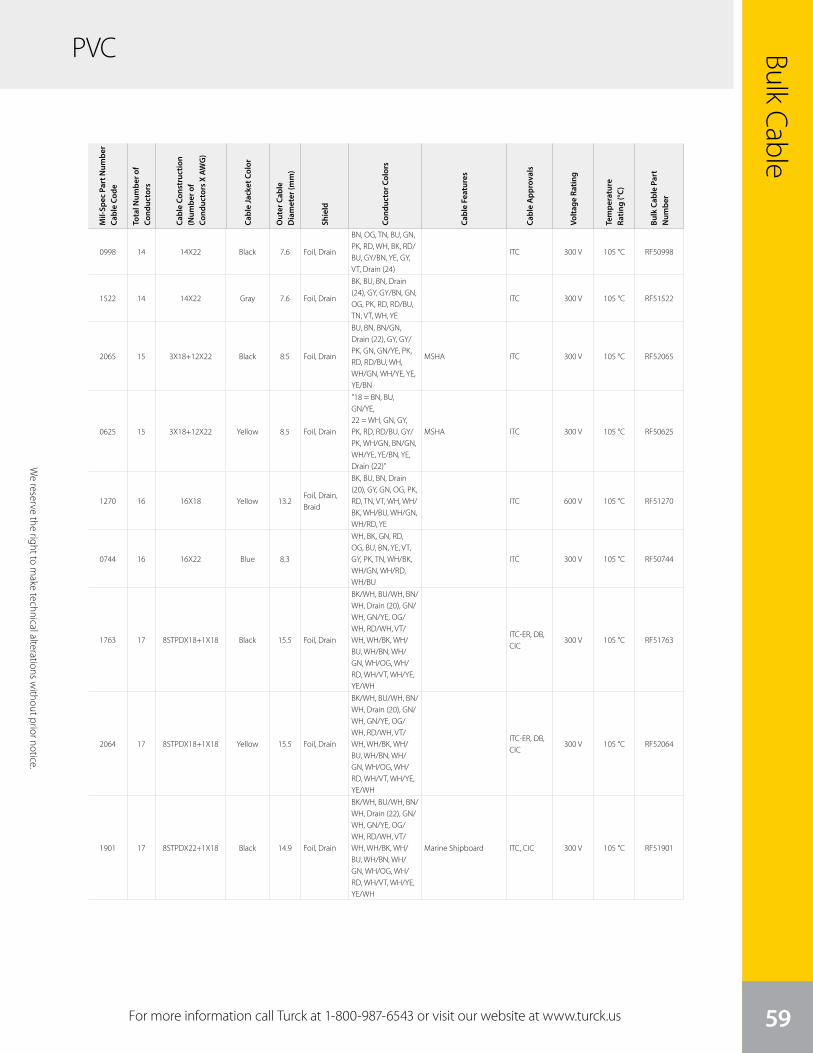
We
rese
rve
the
right
to m
ake
tech
nica
l alte
ratio
ns w
ithou
t prio
r not
ice.
Bulk Cable
59
PVC
For more information call Turck at 1-800-987-6543 or visit our website at www.turck.us
We reserve the right to m
ake technical alterations without prior notice.
Mil-
Spec
Par
t Num
ber
Cabl
e Co
de
Tota
l Num
ber o
f Co
nduc
tors
Cabl
e Co
nstr
uctio
n (N
umbe
r of
Cond
ucto
rs X
AW
G)
Cabl
e Ja
cket
Col
or
Out
er C
able
D
iam
eter
(mm
)
Shie
ld
Cond
ucto
r Col
ors
Cabl
e Fe
atur
es
Cabl
e A
ppro
vals
Volta
ge R
atin
g
Tem
pera
ture
Ra
ting
(°C)
Bulk
Cab
le P
art
Num
ber
0998 14 14X22 Black 7.6 Foil, Drain
BN, OG, TN, BU, GN, PK, RD, WH, BK, RD/BU, GY/BN, YE, GY, VT, Drain (24)
ITC 300 V 105 °C RF50998
1522 14 14X22 Gray 7.6 Foil, Drain
BK, BU, BN, Drain (24), GY, GY/BN, GN, OG, PK, RD, RD/BU, TN, VT, WH, YE
ITC 300 V 105 °C RF51522
2065 15 3X18+12X22 Black 8.5 Foil, Drain
BU, BN, BN/GN, Drain (22), GY, GY/PK, GN, GN/YE, PK, RD, RD/BU, WH, WH/GN, WH/YE, YE, YE/BN
MSHA ITC 300 V 105 °C RF52065
0625 15 3X18+12X22 Yellow 8.5 Foil, Drain
"18 = BN, BU, GN/YE, 22 = WH, GN, GY, PK, RD, RD/BU, GY/PK, WH/GN, BN/GN, WH/YE, YE/BN, YE, Drain (22)”
MSHA ITC 300 V 105 °C RF50625
1270 16 16X18 Yellow 13.2Foil, Drain, Braid
BK, BU, BN, Drain (20), GY, GN, OG, PK, RD, TN, VT, WH, WH/BK, WH/BU, WH/GN, WH/RD, YE
ITC 600 V 105 °C RF51270
0744 16 16X22 Blue 8.3
WH, BK, GN, RD, OG, BU, BN, YE, VT, GY, PK, TN, WH/BK, WH/GN, WH/RD, WH/BU
ITC 300 V 105 °C RF50744
1763 17 8STPDX18+1X18 Black 15.5 Foil, Drain
BK/WH, BU/WH, BN/WH, Drain (20), GN/WH, GN/YE, OG/WH, RD/WH, VT/WH, WH/BK, WH/BU, WH/BN, WH/GN, WH/OG, WH/RD, WH/VT, WH/YE, YE/WH
ITC-ER, DB, CIC
300 V 105 °C RF51763
2064 17 8STPDX18+1X18 Yellow 15.5 Foil, Drain
BK/WH, BU/WH, BN/WH, Drain (20), GN/WH, GN/YE, OG/WH, RD/WH, VT/WH, WH/BK, WH/BU, WH/BN, WH/GN, WH/OG, WH/RD, WH/VT, WH/YE, YE/WH
ITC-ER, DB, CIC
300 V 105 °C RF52064
1901 17 8STPDX22+1X18 Black 14.9 Foil, Drain
BK/WH, BU/WH, BN/WH, Drain (22), GN/WH, GN/YE, OG/WH, RD/WH, VT/WH, WH/BK, WH/BU, WH/BN, WH/GN, WH/OG, WH/RD, WH/VT, WH/YE, YE/WH
Marine Shipboard ITC, CIC 300 V 105 °C RF51901
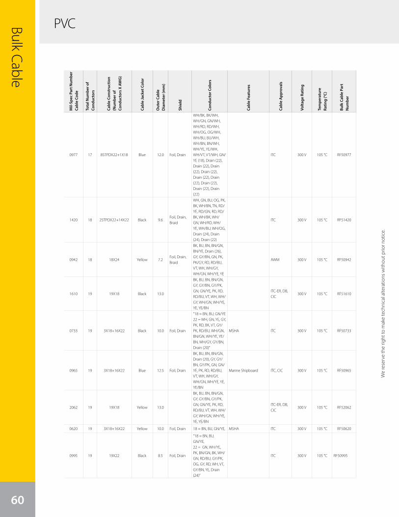
PVCBulk Cable
60
We
rese
rve
the
right
to m
ake
tech
nica
l alte
ratio
ns w
ithou
t prio
r not
ice.
Mil-
Spec
Par
t Num
ber
Cabl
e Co
de
Tota
l Num
ber o
f Co
nduc
tors
Cabl
e Co
nstr
uctio
n (N
umbe
r of
Cond
ucto
rs X
AW
G)
Cabl
e Ja
cket
Col
or
Out
er C
able
D
iam
eter
(mm
)
Shie
ld
Cond
ucto
r Col
ors
Cabl
e Fe
atur
es
Cabl
e A
ppro
vals
Volta
ge R
atin
g
Tem
pera
ture
Ra
ting
(°C)
Bulk
Cab
le P
art
Num
ber
0977 17 8STPDX22+1X18 Blue 12.0 Foil, Drain
WH/BK, BK/WH, WH/GN, GN/WH, WH/RD, RD/WH, WH/OG, OG/WH, WH/BU, BU/WH, WH/BN, BN/WH, WH/YE, YE/WH, WH/VT, VT/WH, GN/YE (18), Drain (22), Drain (22), Drain (22), Drain (22), Drain (22), Drain (22), Drain (22), Drain (22), Drain (22)
ITC 300 V 105 °C RF50977
1420 18 2STPDX22+14X22 Black 9.6Foil, Drain, Braid
WH, GN, BU, OG, PK, BK, WH/BN, TN, RD/YE, RD/GN, RD, RD/BK, WH/BK, WH/GN, WH/RD, WH/YE, WH/BU, WH/OG, Drain (24), Drain (24), Drain (22)
ITC 300 V 105 °C RF51420
0942 18 18X24 Yellow 7.2Foil, Drain, Braid
BK, BU, BN, BN/GN, BN/YE, Drain (26), GY, GY/BN, GN, PK, PK/GY, RD, RD/BU, VT, WH, WH/GY, WH/GN, WH/YE, YE
AWM 300 V 105 °C RF50942
1610 19 19X18 Black 13.0
BK, BU, BN, BN/GN, GY, GY/BN, GY/PK, GN, GN/YE, PK, RD, RD/BU, VT, WH, WH/GY, WH/GN, WH/YE, YE, YE/BN
ITC-ER, DB, CIC
300 V 105 °C RF51610
0733 19 3X18+16X22 Black 10.0 Foil, Drain
"18 = BN, BU, GN/YE 22 = WH, GN, YE, GY, PK, RD, BK, VT, GY/PK, RD/BU, WH/GN, BN/GN, WH/YE, YE/BN, WH/GY, GY/BN, Drain (20)”
MSHA ITC 300 V 105 °C RF50733
0965 19 3X18+16X22 Blue 12.5 Foil, Drain
BK, BU, BN, BN/GN, Drain (20), GY, GY/BN, GY/PK, GN, GN/YE, PK, RD, RD/BU, VT, WH, WH/GY, WH/GN, WH/YE, YE, YE/BN
Marine Shipboard ITC, CIC 300 V 105 °C RF50965
2062 19 19X18 Yellow 13.0
BK, BU, BN, BN/GN, GY, GY/BN, GY/PK, GN, GN/YE, PK, RD, RD/BU, VT, WH, WH/GY, WH/GN, WH/YE, YE, YE/BN
ITC-ER, DB, CIC
300 V 105 °C RF52062
0620 19 3X18+16X22 Yellow 10.0 Foil, Drain 18 = BN, BU, GN/YE, MSHA ITC 300 V 105 °C RF50620
0995 19 19X22 Black 8.5 Foil, Drain
"18 = BN, BU, GN/YE, 22 = GN, WH/YE, PK, BN/GN, BK, WH/GN, RD/BU, GY/PK, OG, GY, RD, WH, VT, GY/BN, YE, Drain (24)”
ITC 300 V 105 °C RF50995
We reserve the right to m
ake technical alterations without prior notice.
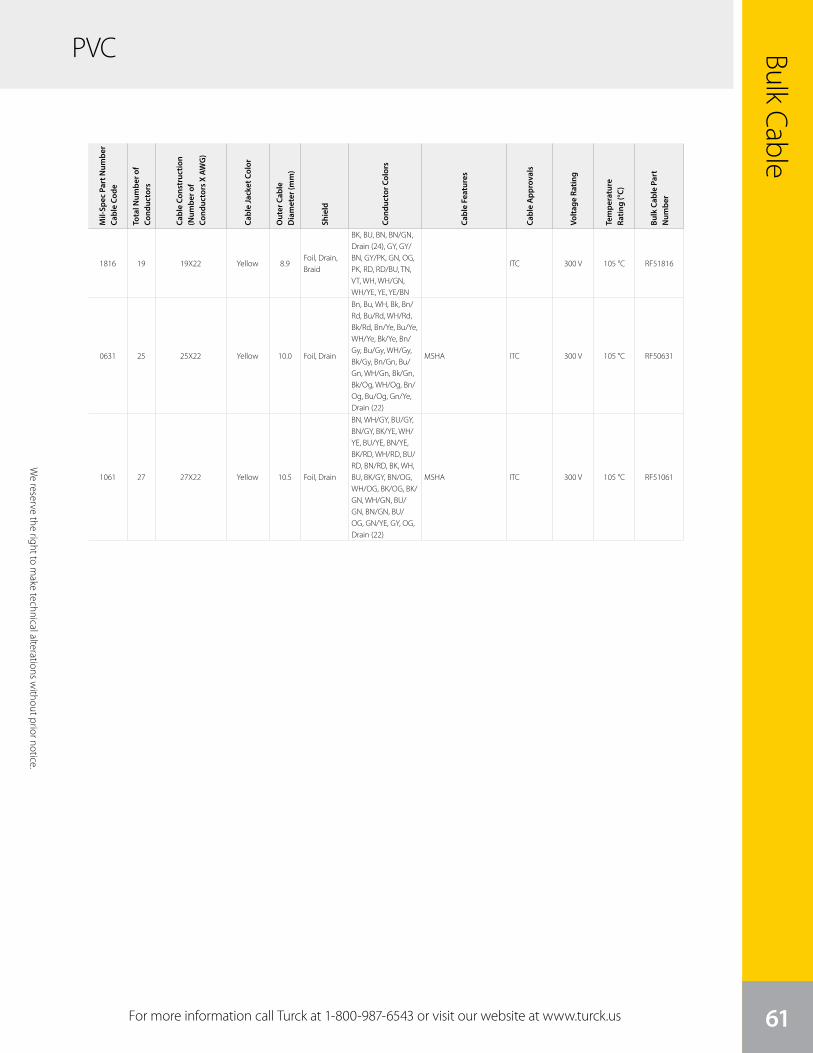
We
rese
rve
the
right
to m
ake
tech
nica
l alte
ratio
ns w
ithou
t prio
r not
ice.
Bulk Cable
61
PVC
Mil-
Spec
Par
t Num
ber
Cabl
e Co
de
Tota
l Num
ber o
f Co
nduc
tors
Cabl
e Co
nstr
uctio
n (N
umbe
r of
Cond
ucto
rs X
AW
G)
Cabl
e Ja
cket
Col
or
Out
er C
able
D
iam
eter
(mm
)
Shie
ld
Cond
ucto
r Col
ors
Cabl
e Fe
atur
es
Cabl
e A
ppro
vals
Volta
ge R
atin
g
Tem
pera
ture
Ra
ting
(°C)
Bulk
Cab
le P
art
Num
ber
For more information call Turck at 1-800-987-6543 or visit our website at www.turck.us
We reserve the right to m
ake technical alterations without prior notice.
1816 19 19X22 Yellow 8.9Foil, Drain, Braid
BK, BU, BN, BN/GN, Drain (24), GY, GY/BN, GY/PK, GN, OG, PK, RD, RD/BU, TN, VT, WH, WH/GN, WH/YE, YE, YE/BN
ITC 300 V 105 °C RF51816
0631 25 25X22 Yellow 10.0 Foil, Drain
Bn, Bu, WH, Bk, Bn/Rd, Bu/Rd, WH/Rd, Bk/Rd, Bn/Ye, Bu/Ye, WH/Ye, Bk/Ye, Bn/Gy, Bu/Gy, WH/Gy, Bk/Gy, Bn/Gn, Bu/Gn, WH/Gn, Bk/Gn, Bk/Og, WH/Og, Bn/Og, Bu/Og, Gn/Ye, Drain (22)
MSHA ITC 300 V 105 °C RF50631
1061 27 27X22 Yellow 10.5 Foil, Drain
BN, WH/GY, BU/GY, BN/GY, BK/YE, WH/YE, BU/YE, BN/YE, BK/RD, WH/RD, BU/RD, BN/RD, BK, WH, BU, BK/GY, BN/OG, WH/OG, BK/OG, BK/GN, WH/GN, BU/GN, BN/GN, BU/OG, GN/YE, GY, OG, Drain (22)
MSHA ITC 300 V 105 °C RF51061
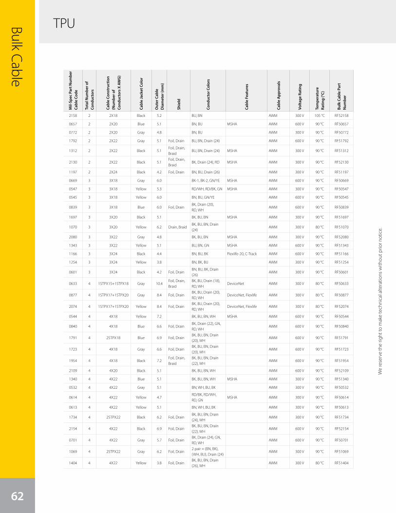
TPUBulk Cable
62
We
rese
rve
the
right
to m
ake
tech
nica
l alte
ratio
ns w
ithou
t prio
r not
ice.
We reserve the right to m
ake technical alterations without prior notice.
Mil-
Spec
Par
t Num
ber
Cabl
e Co
de
Tota
l Num
ber o
f Co
nduc
tors
Cabl
e Co
nstr
uctio
n (N
umbe
r of
Cond
ucto
rs X
AW
G)
Cabl
e Ja
cket
Col
or
Out
er C
able
D
iam
eter
(mm
)
Shie
ld
Cond
ucto
r Col
ors
Cabl
e Fe
atur
es
Cabl
e A
ppro
vals
Volta
ge R
atin
g
Tem
pera
ture
Ra
ting
(°C)
Bulk
Cab
le P
art
Num
ber
2158 2 2X18 Black 5.2 BU, BN AWM 300 V 105 °C RF52158
0657 2 2X20 Blue 5.1 BN, BU MSHA AWM 600 V 90 °C RF50657
0772 2 2X20 Gray 4.8 BN, BU AWM 300 V 90 °C RF50772
1792 2 2X22 Gray 5.1 Foil, Drain BU, BN, Drain (24) AWM 600 V 90 °C RF51792
1312 2 2X22 Black 5.1Foil, Drain, Braid
BU, BN, Drain (24) MSHA AWM 300 V 90 °C RF51312
2130 2 2X22 Black 5.1Foil, Drain, Braid
BK, Drain (24), RD MSHA AWM 300 V 90 °C RF52130
1197 2 2X24 Black 4.2 Foil, Drain BN, BU, Drain (26) AWM 300 V 90 °C RF51197
0669 3 3X18 Gray 6.0 BK-1, BK-2, GN/YE MSHA AWM 600 V 90 °C RF50669
0547 3 3X18 Yellow 5.3 RD/WH, RD/BK, GN MSHA AWM 300 V 90 °C RF50547
0545 3 3X18 Yellow 6.0 BN, BU, GN/YE AWM 600 V 90 °C RF50545
0839 3 3X18 Blue 6.0 Foil, DrainBK, Drain (20), RD, WH
AWM 600 V 90 °C RF50839
1697 3 3X20 Black 5.1 BK, BU, BN MSHA AWM 300 V 90 °C RF51697
1070 3 3X20 Yellow 6.2 Drain, BraidBK, BU, BN, Drain (24)
AWM 300 V 80 °C RF51070
2080 3 3X22 Gray 4.8 BK, BU, BN MSHA AWM 300 V 90 °C RF52080
1343 3 3X22 Yellow 5.1 BU, BN, GN MSHA AWM 600 V 90 °C RF51343
1166 3 3X24 Black 4.4 BN, BU, BK Flexlife-20, C-Track AWM 600 V 90 °C RF51166
1254 3 3X24 Yellow 3.8 BN, BK, BU AWM 300 V 90 °C RF51254
0601 3 3X24 Black 4.2 Foil, DrainBN, BU, BK, Drain (26)
AWM 300 V 90 °C RF50601
0633 4 1STPX15+1STPX18 Gray 10.4Foil, Drain, Braid
BK, BU, Drain (18), RD, WH
DeviceNet AWM 300 V 80 °C RF50633
0877 4 1STPX17+1STPX20 Gray 8.4 Foil, DrainBK, BU, Drain (20), RD, WH
DeviceNet, Flexlife AWM 300 V 80 °C RF50877
2074 4 1STPX17+1STPX20 Yellow 8.4 Foil, DrainBK, BU, Drain (20), RD, WH
DeviceNet, Flexlife AWM 300 V 80 °C RF52074
0544 4 4X18 Yellow 7.2 BK, BU, BN, WH MSHA AWM 600 V 90 °C RF50544
0840 4 4X18 Blue 6.6 Foil, DrainBK, Drain (22), GN, RD, WH
AWM 600 V 90 °C RF50840
1791 4 2STPX18 Blue 6.9 Foil, DrainBK, BU, BN, Drain (20), WH
AWM 600 V 90 °C RF51791
1723 4 4X18 Gray 6.6 Foil, DrainBK, BU, BN, Drain (20), WH
AWM 600 V 90 °C RF51723
1954 4 4X18 Black 7.2Foil, Drain, Braid
BK, BU, BN, Drain (22), WH
AWM 600 V 90 °C RF51954
2109 4 4X20 Black 5.1 BK, BU, BN, WH AWM 600 V 90 °C RF52109
1340 4 4X22 Blue 5.1 BK, BU, BN, WH MSHA AWM 300 V 90 °C RF51340
0532 4 4X22 Gray 5.1 BN, WH, BU, BK AWM 300 V 90 °C RF50532
0614 4 4X22 Yellow 4.7RD/BK, RD/WH, RD, GN
MSHA AWM 300 V 90 °C RF50614
0613 4 4X22 Yellow 5.1 BN, WH, BU, BK AWM 300 V 90 °C RF50613
1734 4 2STPX22 Black 6.2 Foil, DrainBK, BU, BN, Drain (24), WH
AWM 300 V 90 °C RF51734
2154 4 4X22 Black 6.9 Foil, DrainBK, BU, BN, Drain (22), WH
AWM 600 V 90 °C RF52154
0701 4 4X22 Gray 5.7 Foil, DrainBK, Drain (24), GN, RD, WH
AWM 600 V 90 °C RF50701
1069 4 2STPX22 Gray 6.2 Foil, Drain2 pair = (BN, BK), (WH, BU), Drain (24)
AWM 300 V 90 °C RF51069
1404 4 4X22 Yellow 3.8 Foil, DrainBK, BU, BN, Drain (26), WH
AWM 300 V 80 °C RF51404

We
rese
rve
the
right
to m
ake
tech
nica
l alte
ratio
ns w
ithou
t prio
r not
ice.
Bulk Cable
63
TPU
For more information call Turck at 1-800-987-6543 or visit our website at www.turck.us
We reserve the right to m
ake technical alterations without prior notice.
Mil-
Spec
Par
t Num
ber
Cabl
e Co
de
Tota
l Num
ber o
f Co
nduc
tors
Cabl
e Co
nstr
uctio
n (N
umbe
r of
Cond
ucto
rs X
AW
G)
Cabl
e Ja
cket
Col
or
Out
er C
able
D
iam
eter
(mm
)
Shie
ld
Cond
ucto
r Col
ors
Cabl
e Fe
atur
es
Cabl
e A
ppro
vals
Volta
ge R
atin
g
Tem
pera
ture
Ra
ting
(°C)
Bulk
Cab
le P
art
Num
ber
0810 4 4X22 Gray 6.2Foil, Drain, Braid
BN, WH, BU, BK, Drain (22)
AWM 600 V 90 °C RF50810
1746 4 2X22+2X24 Yellow 5.1Foil, Drain, Braid
BK, BU, BN, Drain (24), WH
AWM 300 V 90 °C RF51746
1477 4 4X24 Black 3.8 BK, BU, BN, WH AWM 300 V 90 °C RF51477
1256 4 4X24 Yellow 3.8 BN, BK, BU, WH AWM 300 V 90 °C RF51256
0935 4 4X26 Black 4.4 BN, WH, BU, BK Flexlife-20, C-Track AWM 600 V 90 °C RF50935
1481 5 5X16 Yellow 8.0 BK, GN, OG, RD, WH AWM 600 V 90 °C RF51481
1914 5 5X18 Black 7.2BK, BU, BN, GN/YE, WH
MSHA AWM 600 V 90 °C RF51914
1656 5 5X18 Gray 7.2 BK, BU, BN, GY, WH AWM 600 V 90 °C RF51656
0751 5 5X18 Yellow 7.2WH, BK, BU, GN/YE, BN
MSHA AWM 600 V 90 °C RF50751
2073 5 3X18+2X20 Gray 7.2 Foil, DrainBK, BK/WH, BU, BN, Drain (20), GN/YE
AWM 600 V 90 °C RF52073
1521 5 3X20+1STPDX24 Black 6.7 BraidBK, BU, Drain (24), RD, RD/BK, WH
AWM 300 V 80 °C RF51521
0649 5 5X22 Gray 5.3 GY, BN, WH, BU, BK MSHA AWM 300 V 90 °C RF50649
1552 5 5X22 Yellow 5.3 BK, BU, BN, GY, WH AWM 300 V 90 °C RF51552
1507 5 5X22 Black 5.7Foil, Drain, Braid
BK, BU, BN, Drain (24), GY, WH
AWM 300 V 90 °C RF51507
1856 5 5X24 Black 4.5 BK, BU, BN, GY, WH AWM 300 V 90 °C RF51856
0928 5 5X24 Blue 5.7 Foil, DrainBU, OG, RD, YE, BK, Drain (24)
MSHA AWM 600 V 90 °C RF50928
1137 6 6X16 Yellow 9.0BK, WH, RD, OG, BU, GN
AWM 600 V 90 °C RF51137
0662 6 6X18 Yellow 6.7 Foil, DrainWH, GN, YE, GY, BN, BU, Drain (20)
AWM 300 V 90 °C RF50662
2088 6 1UTPX20+4X20 Black 7.1BK, BU, GN, OG, RD, YE
AWM 300 V 80 °C RF52088
0728 6 6X24 Black 5.1GY, BN, WH, PK, BU, BK
MSHA AWM 300 V 90 °C RF50728
0646 6 6X24 Gray 5.1GY, BN, WH, PK, BU, BK
MSHA AWM 300 V 90 °C RF50646
1120 6 6X24 Yellow 6.2 BraidBN, WH, PK, BU, BK, GY
AWM 300 V 90 °C RF51120
1541 6 3STPX24 Black 7.2 Drain, Braid
BU/WH, Drain (24), GN/WH, OG/WH, WH/BU, WH/GN, WH/OG
AWM 300 V 80 °C RF51541
1082 6 6X26 Black 5.1BN, WH, BU, BK, GY, PK
Flexlife-20, C-Track AWM 600 V 90 °C RF51082
1138 7 7X16 Yellow 9.0BK, WH, RD, OG, BU, GN, WH/BK
AWM 600 V 90 °C RF51138
0676 7 7X18 Yellow 6.7 Foil, DrainWH, GN, YE, GY, BN, BU, GN/YE, Drain (20)
MSHA AWM 300 V 90 °C RF50676
2179 7 7X20 Black 6.6BU/BK, GN/BK, OG/BK, RD, RD/BK, WH/BK, YE/BK
AWM 300 V 80 °C RF52179
1139 8 8X16 Yellow 10.0BU, WH/BK, BK, WH, RD, RD/BK, GN, OG
AWM 600 V 90 °C RF51139
1680 8 8X24 Black 5.7BU, BN, GY, GN, PK, RD, WH, YE
MSHA AWM 300 V 90 °C RF51680
0984 8 8X24 Gray 5.7BU, WH, BN, GN, YE, GY, PK, RD
MSHA AWM 300 V 90 °C RF50984
1994 8 8X24 Yellow 5.7BU, BN, GY, GN, PK, RD, WH, YE
MSHA AWM 300 V 90 °C RF51994
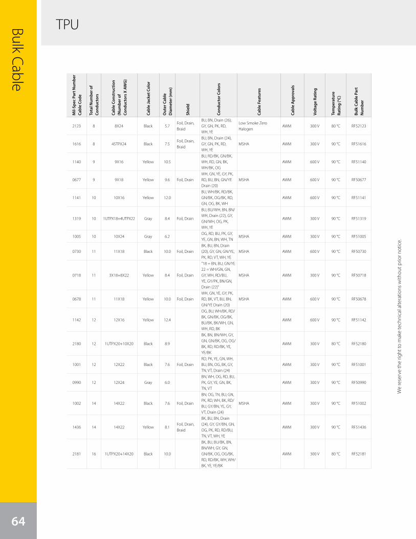
TPUBulk Cable
64
Mil-
Spec
Par
t Num
ber
Cabl
e Co
de
Tota
l Num
ber o
f Co
nduc
tors
Cabl
e Co
nstr
uctio
n (N
umbe
r of
Cond
ucto
rs X
AW
G)
Cabl
e Ja
cket
Col
or
Out
er C
able
D
iam
eter
(mm
)
Shie
ld
Cond
ucto
r Col
ors
Cabl
e Fe
atur
es
Cabl
e A
ppro
vals
Volta
ge R
atin
g
Tem
pera
ture
Ra
ting
(°C)
Bulk
Cab
le P
art
Num
ber
2123 8 8X24 Black 5.7Foil, Drain, Braid
BU, BN, Drain (26), GY, GN, PK, RD, WH, YE
Low Smoke Zero Halogen
AWM 300 V 80 °C RF52123
1616 8 4STPX24 Black 7.5Foil, Drain, Braid
BU, BN, Drain (24), GY, GN, PK, RD, WH, YE
MSHA AWM 300 V 90 °C RF51616
1140 9 9X16 Yellow 10.5BU, RD/BK, GN/BK, WH, RD, GN, BK, WH/BK, OG
AWM 600 V 90 °C RF51140
0677 9 9X18 Yellow 9.6 Foil, DrainWH, GN, YE, GY, PK, RD, BU, BN, GN/YE Drain (20)
MSHA AWM 600 V 90 °C RF50677
1141 10 10X16 Yellow 12.0BU, WH/BK, RD/BK, GN/BK, OG/BK, RD, GN, OG, BK, WH
AWM 600 V 90 °C RF51141
1319 10 1UTPX18+4UTPX22 Gray 8.4 Foil, Drain
BU, BU/WH, BN, BN/WH, Drain (22), GY, GN/WH, OG, PK, WH, YE
AWM 300 V 90 °C RF51319
1005 10 10X24 Gray 6.2OG, RD, BU, PK, GY, YE, GN, BN, WH, TN
MSHA AWM 300 V 90 °C RF51005
0730 11 11X18 Black 10.0 Foil, DrainBK, BU, BN, Drain (20), GY, GN, GN/YE, PK, RD, VT, WH, YE
MSHA AWM 600 V 90 °C RF50730
0718 11 3X18+8X22 Yellow 8.4 Foil, Drain
"18 = BN, BU, GN/YE22 = WH/GN, GN, GY, WH, RD/BU, YE, GY/PK, BN/GN, Drain (22)”
MSHA AWM 300 V 90 °C RF50718
0678 11 11X18 Yellow 10.0 Foil, DrainWH, GN, YE, GY, PK, RD, BK, VT, BU, BN, GN/YE Drain (20)
MSHA AWM 600 V 90 °C RF50678
1142 12 12X16 Yellow 12.4
OG, BU, WH/BK, RD/BK, GN/BK, OG/BK, BU/BK, BK/WH, GN, WH, RD, BK
AWM 600 V 90 °C RF51142
2180 12 1UTPX20+10X20 Black 8.9
BK, BN, BN/WH, GY, GN, GN/BK, OG, OG/BK, RD, RD/BK, YE, YE/BK
AWM 300 V 80 °C RF52180
1001 12 12X22 Black 7.6 Foil, DrainRD, PK, YE, GN, WH, BU, BN, OG, BK, GY, TN, VT, Drain (24)
AWM 300 V 90 °C RF51001
0990 12 12X24 Gray 6.0BN, WH, OG, RD, BU, PK, GY, YE, GN, BK, TN, VT
AWM 300 V 90 °C RF50990
1002 14 14X22 Black 7.6 Foil, Drain
BN, OG, TN, BU, GN, PK, RD, WH, BK, RD/BU, GY/BN, YE, GY, VT, Drain (24)
MSHA AWM 300 V 90 °C RF51002
1436 14 14X22 Yellow 8.1Foil, Drain, Braid
BK, BU, BN, Drain (24), GY, GY/BN, GN, OG, PK, RD, RD/BU, TN, VT, WH, YE
AWM 300 V 90 °C RF51436
2181 16 1UTPX20+14X20 Black 10.0
BK, BU, BU/BK, BN, BN/WH, GY, GN, GN/BK, OG, OG/BK, RD, RD/BK, WH, WH/BK, YE, YE/BK
AWM 300 V 80 °C RF52181
We
rese
rve
the
right
to m
ake
tech
nica
l alte
ratio
ns w
ithou
t prio
r not
ice.
We reserve the right to m
ake technical alterations without prior notice.
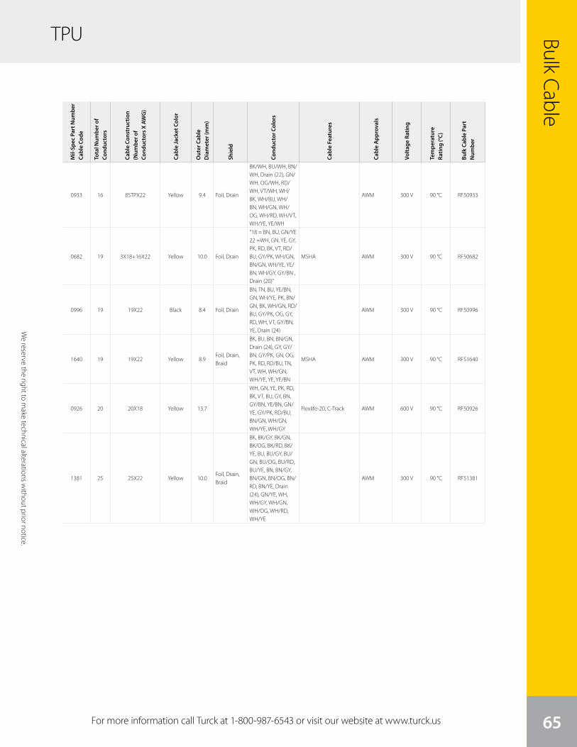
We
rese
rve
the
right
to m
ake
tech
nica
l alte
ratio
ns w
ithou
t prio
r not
ice.
Bulk Cable
65
TPU
Mil-
Spec
Par
t Num
ber
Cabl
e Co
de
Tota
l Num
ber o
f Co
nduc
tors
Cabl
e Co
nstr
uctio
n (N
umbe
r of
Cond
ucto
rs X
AW
G)
Cabl
e Ja
cket
Col
or
Out
er C
able
D
iam
eter
(mm
)
Shie
ld
Cond
ucto
r Col
ors
Cabl
e Fe
atur
es
Cabl
e A
ppro
vals
Volta
ge R
atin
g
Tem
pera
ture
Ra
ting
(°C)
Bulk
Cab
le P
art
Num
ber
0933 16 8STPX22 Yellow 9.4 Foil, Drain
BK/WH, BU/WH, BN/WH, Drain (22), GN/WH, OG/WH, RD/WH, VT/WH, WH/BK, WH/BU, WH/BN, WH/GN, WH/OG, WH/RD, WH/VT, WH/YE, YE/WH
AWM 300 V 90 °C RF50933
0682 19 3X18+16X22 Yellow 10.0 Foil, Drain
"18 = BN, BU, GN/YE22 =WH, GN, YE, GY, PK, RD, BK, VT, RD/BU, GY/PK, WH/GN, BN/GN, WH/YE, YE/BN, WH/GY, GY/BN , Drain (20)”
MSHA AWM 300 V 90 °C RF50682
0996 19 19X22 Black 8.4 Foil, Drain
BN, TN, BU, YE/BN, GN, WH/YE, PK, BN/GN, BK, WH/GN, RD/BU, GY/PK, OG, GY, RD, WH, VT, GY/BN, YE, Drain (24)
AWM 300 V 90 °C RF50996
1640 19 19X22 Yellow 8.9Foil, Drain, Braid
BK, BU, BN, BN/GN, Drain (24), GY, GY/BN, GY/PK, GN, OG, PK, RD, RD/BU, TN, VT, WH, WH/GN, WH/YE, YE, YE/BN
MSHA AWM 300 V 90 °C RF51640
0926 20 20X18 Yellow 13.7
WH, GN, YE, PK, RD, BK, VT, BU, GY, BN, GY/BN, YE/BN, GN/YE, GY/PK, RD/BU, BN/GN, WH/GN, WH/YE, WH/GY
Flexlife-20, C-Track AWM 600 V 90 °C RF50926
1381 25 25X22 Yellow 10.0Foil, Drain, Braid
BK, BK/GY, BK/GN, BK/OG, BK/RD, BK/YE, BU, BU/GY, BU/GN, BU/OG, BU/RD, BU/YE, BN, BN/GY, BN/GN, BN/OG, BN/RD, BN/YE, Drain (24), GN/YE, WH, WH/GY, WH/GN, WH/OG, WH/RD, WH/YE
AWM 300 V 90 °C RF51381
For more information call Turck at 1-800-987-6543 or visit our website at www.turck.us
We reserve the right to m
ake technical alterations without prior notice.
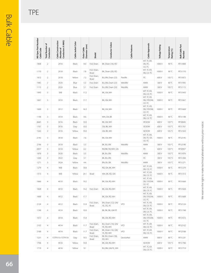
TPEBulk Cable
66
Mil-
Spec
Par
t Num
ber
Cabl
e Co
de
Tota
l Num
ber o
f Co
nduc
tors
Cabl
e Co
nstr
uctio
n (N
umbe
r of
Cond
ucto
rs X
AW
G)
Cabl
e Ja
cket
Col
or
Out
er C
able
D
iam
eter
(mm
)
Shie
ld
Cond
ucto
r Col
ors
Cabl
e Fe
atur
es
Cabl
e A
ppro
vals
Volta
ge R
atin
g
Tem
pera
ture
Ra
ting
(°C)
Bulk
Cab
le P
art
Num
ber
1808 2 2X16 Black 8.0 Foil, Drain BK, Drain (16), RDWT, TC-ER, DB, ITC, CIC-TC
1000 V 90 °C RF51808
1770 2 2X18 Black 7.8Foil, Drain, Braid
BK, Drain (20), RDWT, TC-ER, DB, CIC-TC
1000 V 90 °C RF51770
1872 2 2X18 Yellow 7.2Foil, Drain, Braid
BU, BN, Drain (22) Flexlife ITC 600 V 105 °C RF51872
1945 2 2X20 Blue 5.3 Foil, Drain BU, BN, Drain (22) Weldlife AWM 300 V 80 °C RF51945
1115 2 2X24 Blue 5.1 Foil, Drain BU, BN, Drain (24) Weldlife AWM 300 V 105 °C RF51115
1943 3 3X8 Black 17.2 BK, GN, WHWT, TC-ER, DB, CIC-TC
1000 V 90 °C RF51943
1667 3 3X10 Black 17.7 BK, GN, WHWT, TC-ER, DB, STOOW, CIC-TC
1000 V 90 °C RF51667
1669 3 3X12 Black 16.3 BK, GN, WHWT, TC-ER, DB, STOOW, CIC-TC
1000 V 90 °C RF51669
1198 3 3X14 Black 9.6 WH, GN, BKWT, TC-ER, DB, CIC-TC
1000 V 90 °C RF51198
0645 3 3X16 Black 10.0 BK, GN, WH SEOOW 600 V 105 °C RF50645
1767 3 3X16 Gray 10.0 GN, BK, WH SEOOW 600 V 105 °C RF51767
1563 3 3X16 Yellow 10.0 GN, BK, WH SEOOW 600 V 105 °C RF51563
2145 3 3X18 Black 7.6 BK, GN, WHWT, TC-ER, DB, ITC-ER, CIC-TC
1000 V 90 °C RF52145
2196 3 3X18 Black 5.3 BK, BU, BN Weldlife AWM 300 V 105 °C RF52196
0957 3 3X18 Yellow 6.2 RD/BK, RD/WH, GN ITC 600 V 105 °C RF50957
1876 3 3X20 Black 5.3 BK, BU, BN Weldlife AWM 300 V 105 °C RF51876
1266 3 3X22 Gray 5.1 BK, BU, BN ITC 300 V 105 °C RF51266
1271 3 3X24 Yellow 4.4 BN, BU, BK Weldlife AWM 300 V 105 °C RF51271
1279 4 4X8 Black 18.8 RD, GN, BK, WHWT, TC-ER, DB, CIC-TC
1000 V 90 °C RF51279
1313 4 4X8 Yellow 20.1 Braid WH, BK, RD, GNWT, TC-ER, DB, CIC-TC
1000 V 90 °C RF51313
1666 4 4X10 Black 19.2 BK, GN, RD, WHWT, TC-ER, DB, STOOW, CIC-TC
1000 V 90 °C RF51666
1828 4 4X10 Black 14.2 Foil, Drain BK, GN, RD, WHWT, TC-ER, DB, CIC-TC
1000 V 90 °C RF51828
1668 4 4X12 Black 17.7 BK, GN, RD, WHWT, TC-ER, DB, STOOW, CIC-TC
1000 V 90 °C RF51668
2124 4 4X12 Black 15.9Foil, Drain, Braid
BN, Drain (12), GN/YE, OG, YE
VFDWT, TC-ER, DB, CIC-TC
1000 V 90 °C RF52124
1748 4 4X14 Black 10.0 BK, BK, BK, GN/YEWT, TC-ER, DB, CIC-TC
1000 V 90 °C RF51748
1672 4 4X14 Black 15.4 BK, GN, RD, WHWT, TC-ER, DB, STOOW, CIC-TC
1000 V 90 °C RF51672
2102 4 4X14 Black 11.7Foil, Drain, Braid
BU, Drain (14), GN/YE, RD, WH
VFDWT, TC-ER, DB, CIC-TC
1000 V 90 °C RF52102
2188 4 4X14 Black 11.7Foil, Drain, Braid
BK, Drain (14), GN/YE, RD, WH
VFDWT, TC-ER, DB, CIC-TC
1000 V 90 °C RF52188
1231 4 1STPX15+1STPX18 Gray 10.5Foil, Drain, Braid
BK, BU, Drain (18), RD, WH
DeviceNet AWM 600 V 80 °C RF51231
1706 4 4X16 Yellow 10.8 BK, GN, RD, WH SEOOW 600 V 105 °C RF51706
1719 4 4X16 Yellow 9.1 BU, BN, GN/YE, WHWT, TC-ER, DB, CIC-TC
1000 V 90 °C RF51719
We
rese
rve
the
right
to m
ake
tech
nica
l alte
ratio
ns w
ithou
t prio
r not
ice.
We reserve the right to m
ake technical alterations without prior notice.
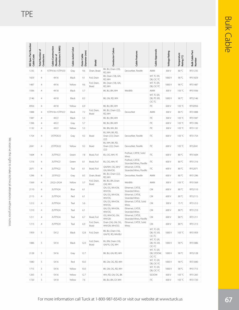
We
rese
rve
the
right
to m
ake
tech
nica
l alte
ratio
ns w
ithou
t prio
r not
ice.
Bulk Cable
67
TPE
Mil-
Spec
Par
t Num
ber
Cabl
e Co
de
Tota
l Num
ber o
f Co
nduc
tors
Cabl
e Co
nstr
uctio
n (N
umbe
r of
Cond
ucto
rs X
AW
G)
Cabl
e Ja
cket
Col
or
Out
er C
able
D
iam
eter
(mm
)
Shie
ld
Cond
ucto
r Col
ors
Cabl
e Fe
atur
es
Cabl
e A
ppro
vals
Volta
ge R
atin
g
Tem
pera
ture
Ra
ting
(°C)
Bulk
Cab
le P
art
Num
ber
1235 4 1STPX16+1STPX20 Gray 9.6 Drain, BraidBK, BU, Drain (20), RD, WH
DeviceNet, Flexlife AWM 300 V 80 °C RF51235
1829 4 4X16 Black 9.1 Foil, DrainBK, Drain (18), GN, RD, WH
WT, TC-ER, DB, CIC-TC
1000 V 90 °C RF51829
1487 4 4X16 Yellow 9.6Foil, Drain, Braid
BK, Drain (18), GN, RD, WH
WT, TC-ER, DB, CIC-TC
1000 V 90 °C RF51487
1936 4 4X18 Black 5.7 BK, BU, BN, WH Weldlife AWM 300 V 105 °C RF51936
2146 4 4X18 Black 8.3 BK, GN, RD, WHWT, TC-ER, DB, ITC-ER, CIC-TC
1000 V 90 °C RF52146
0956 4 4X18 Yellow 6.9 BK, BU, BN, WH ITC 600 V 105 °C RF50956
1888 4 1STPX18+1STPX22 Black 7.2Foil, Drain, Braid
BK, BU, Drain (22), RD, WH
DeviceNet AWM 300 V 80 °C RF51888
1947 4 4X22 Black 5.3 BK, BU, BN, WH ITC 300 V 105 °C RF51947
1396 4 4X22 Gray 5.7 BK, BU, BN, WH ITC 600 V 105 °C RF51396
1132 4 4X22 Yellow 5.3 BK, BN, WH, BU ITC 300 V 105 °C RF51132
1754 4 2STPDX22 Gray 9.3 BraidBU, WH, BK, RD, Drain (22), Drain (22)
DeviceNet, Flexlife ITC 600 V 105 °C RF51754
2041 4 2STPDX22 Yellow 9.3 BraidBU, WH, BK, RD, Drain (22), Drain (22)
DeviceNet, Flexlife ITC 600 V 105 °C RF52041
1604 4 2UTPX22 Green 7.8 Braid, Foil BU, OG, WH, YEProfinet, CAT5E, Solid Wires
ITC 600 V 80 °C RF51604
1216 4 2UTPX22 Green 8.1 Braid, Foil BU, OG, WH, YEProfinet, CAT5E, Stranded Wires, Flexlife
ITC 600 V 80 °C RF51216
2071 4 2UTPX22 Teal 8.1 Braid, FoilGN/WH, OG, WH/GN, WH/OG
Ethernet, CAT5E, Stranded Wires, Flexlife
ITC 600 V 80 °C RF52071
1296 4 2STPX22 Gray 8.5 Drain, BraidBK, BU, Drain (22), RD, WH
DeviceNet, Flexlife AWM 600 V 80 °C RF51296
1569 4 2X22+2X24 Yellow 5.7Foil, Drain, Braid
BK, BU, BN, Drain (24), WH
Weldlife AWM 300 V 105 °C RF51569
2110 4 2UTPX24 Blue 6.1GN, OG, WH/GN, WH/OG
Ethernet, CAT5E, Stranded Wires
CM 600 V 80 °C RF52110
2115 4 2UTPX24 Red 6.1GN, OG, WH/GN, WH/OG
Ethernet, CAT5E, Stranded Wires
CM 600 V 80 °C RF52115
1212 4 2UTPX24 Teal 5.6GN, OG, WH/GN, WH/OG
Ethernet, CAT5E, Solid Wires
CM 300 V 75 °C RF51212
1210 4 2UTPX24 Teal 6.1GN, OG, WH/GN, WH/OG
Ethernet, CAT5E, Stranded Wires
CM 600 V 80 °C RF51210
1211 4 2UTPX24 Teal 6.7 Braid, FoilOG, WH/OG, GN, WH/GN
Ethernet, CAT5E, Stranded Wires, Flexlife
CM 600 V 80 °C RF51211
1213 4 2UTPX24 Teal 6.9Foil, Drain, Braid
Drain (24), GN, OG, WH/GN, WH/OG
Ethernet, CAT5E, Solid Wires
CM 600 V 80 °C RF51213
1959 5 5X12 Black 12.8 Foil, DrainBK, BU, Drain (16), GN/YE, RD, WH/BU
WT, TC-ER, DB, ITC-ER, CIC-TC
1000 V 105 °C RF51959
1886 5 5X14 Black 12.0Foil, Drain, Braid
BU, BN, Drain (18), GN/YE, OG, WH
WT, TC-ER, DB, ITC-ER, CIC-TC
1000 V 90 °C RF51886
2128 5 5X16 Gray 12.7 BK, BU, GN, RD, WHWT, TC-ER, DB, STOOW, CIC-TC
1000 V 90 °C RF52128
1840 5 5X16 Red 10.0 BK, GN, OG, RD, WHWT, TC-ER, DB, CIC-TC
1000 V 90 °C RF51840
1715 5 5X16 Yellow 10.0 BK, GN, OG, RD, WHWT, TC-ER, DB, CIC-TC
1000 V 90 °C RF51715
1265 5 5X16 Yellow 12.7 WH, RD, GN, OG, BK SEOOW 600 V 105 °C RF51265
1720 5 5X18 Yellow 7.6 BK, BU, BN, GY, WH ITC 600 V 105 °C RF51720
For more information call Turck at 1-800-987-6543 or visit our website at www.turck.us
We reserve the right to m
ake technical alterations without prior notice.

TPE
Mil-
Spec
Par
t Num
ber
Cabl
e Co
de
Tota
l Num
ber o
f Co
nduc
tors
Cabl
e Co
nstr
uctio
n (N
umbe
r of
Cond
ucto
rs X
AW
G)
Cabl
e Ja
cket
Col
or
Out
er C
able
D
iam
eter
(mm
)
Shie
ld
Cond
ucto
r Col
ors
Cabl
e Fe
atur
es
Cabl
e A
ppro
vals
Volta
ge R
atin
g
Tem
pera
ture
Ra
ting
(°C)
Bulk
Cab
le P
art
Num
ber
TPEBulk Cable
68
0958 5 5X18 Yellow 7.6RD/BU, GN, RD/OG, RD/BK, RD/WH
ITC 600 V 105 °C RF50958
1898 5 5X22 Yellow 5.7 BK, BU, BN, GY, WH ITC 300 V 105 °C RF51898
1963 6 4X10+2X14 Black 20.6
"14 = BU/YEL (-), BU/YE (+)10 = BK V, BK U, GN/YE, BK W”
WT, TC-ER, DB, STOOW, CIC-TC
1000 V 90 °C RF51963
1059 6 6X12 Yellow 14.7BK, RD, BU, OG, YE, BN
WT, TC-ER, DB, CIC-TC
1000 V 90 °C RF51059
1716 6 6X16 Yellow 11.1BK, BU, GN, OG, RD, WH
WT, TC-ER, DB, CIC-TC
1000 V 90 °C RF51716
1564 6 6X16 Yellow 13.6WH, RD, GN, OG, BK, BU
SEOOW 600 V 105 °C RF51564
2132 6 6X18 Black 9.6BK, BU, GN, OG, RD, WH
WT, TC-ER, DB, ITC-ER, CIC-TC
1000 V 90 °C RF52132
1274 6 6X18 Gray 7.9GN, YE, GY, BN, BU, WH
ITC 300 V 105 °C RF51274
1009 7 7X16 Yellow 9.6BK, WH, RD, OG, BU, GN, WH/BK
ITC 600 V 105 °C RF51009
1314 8 4X8+4X18 Black 18.8"8 = WH, RD, GN, BK 18 = BU, BN, WH, BK”
WT, TC-ER, DB, CIC-TC
1000 V 90 °C RF51314
1287 8 4X12+4X18 Yellow 13.2
"12= BU, GN, WH, BK18= OG, RD, WH/BK, RD/BK”
WT, TC-ER, DB, CIC-TC
1000 V 90 °C RF51287
1011 8 8X16 Yellow 10.0BU, WH/BK, BK, WH, RD, RD/BK, GN, OG
ITC 600 V 105 °C RF51011
2156 8 8X18 Black 10.2BK, BU, GN, OG, RD, RD/BK, WH, WH/BK
WT, TC-ER, DB, ITC-ER, CIC-TC
1000 V 90 °C RF52156
1692 8 8X18 Black 11.2Foil, Drain, Braid
BK, BU, BN, Drain (20), OG, RD, TN, VT, YE
WT, TC-ER, DB, ITC-ER, CIC-TC
1000 V 105 °C RF51692
2113 8 4UTPX22 Teal 8.8 Braid, FoilBU, BN, GN/WH, OG, WH/BU, WH/BN, WH/GN, WH/OG
Ethernet, CAT5E, Stranded Wires, Flexlife
ITC 600 V 80 °C RF52113
2151 8 4UTPX24 Red 6.3BU, BN, GN, OG, WH/BU, WH/BN, WH/GN, WH/OG
Flexlife, Ethernet, CAT5E, Stranded Wires
CM 600 V 80 °C RF52151
1462 8 4UTPX24 Teal 6.1BU, BN, GN, OG, WH/BU, WH/BN, WH/GN, WH/OG
Ethernet, CAT5E, Solid Wires
CM 300 V 75 °C RF51462
1460 8 4UTPX24 Teal 6.3BU, BN, GN, OG, WH/BU, WH/BN, WH/GN, WH/OG
Flexlife, Ethernet, CAT5E, Stranded Wires
CM 600 V 80 °C RF51460
2173 8 8X24 Yellow 5.7BU, BN, GY, GN, PK, RD, WH, YE
Weldlife AWM 300 V 105 °C RF52173
1624 8 4UTPX24 Black 7.7 Braid, FoilBU, BN, GN, OG, WH/BU, WH/BN, WH/GN, WH/OG
Flexlife, Ethernet, CAT5E, Stranded Wires
CM 600 V 80 °C RF51624
1348 8 4UTPX24 Gray 7.7 Braid, FoilBU, BN, GN, OG, WH/BU, WH/BN, WH/GN, WH/OG
Flexlife, Ethernet, CAT5E, Stranded Wires
CM 600 V 80 °C RF51348
0893 8 4UTPX24 Teal 7.7 Braid, FoilBU, BN, GN, OG, WH/BU, WH/BN, WH/GN, WH/OG
Flexlife, Ethernet, CAT5E, Stranded Wires
CM 600 V 80 °C RF50893
1756 8 4STPX24 Black 6.7 Foil, DrainBU, BN, Drain (26), GY, GN, PK, RD, WH, YE
Weldlife AWM 600 V 105 °C RF51756
1757 8 4UTPX24 Black 6.2 Foil, DrainBU, BN, Drain (26), GY, GN, PK, RD, WH, YE
Weldlife AWM 600 V 105 °C RF51757
We
rese
rve
the
right
to m
ake
tech
nica
l alte
ratio
ns w
ithou
t prio
r not
ice.
We reserve the right to m
ake technical alterations without prior notice.

We
rese
rve
the
right
to m
ake
tech
nica
l alte
ratio
ns w
ithou
t prio
r not
ice.
TPE
Mil-
Spec
Par
t Num
ber
Cabl
e Co
de
Tota
l Num
ber o
f Co
nduc
tors
Cabl
e Co
nstr
uctio
n (N
umbe
r of
Cond
ucto
rs X
AW
G)
Cabl
e Ja
cket
Col
or
Out
er C
able
D
iam
eter
(mm
)
Shie
ld
Cond
ucto
r Col
ors
Cabl
e Fe
atur
es
Cabl
e A
ppro
vals
Volta
ge R
atin
g
Tem
pera
ture
Ra
ting
(°C)
Bulk
Cab
le P
art
Num
ber
Bulk Cable
69
TPE
1463 8 4UTPX24 Teal 7.2Foil, Drain, Braid
BU, BN, Drain (24), GN, OG, WH/BU, WH/BN, WH/GN, WH/OG
Ethernet, CAT5E, Solid Wires
CM 600 V 80 °C RF51463
1013 9 9X16 Yellow 11.2BU, RD/BK, GN/BK, WH, RD, GN, BK, WH/BK, OG
ITC 600 V 105 °C RF51013
1751 10 10X16 Yellow 14.2BK, BU, GN, GN/BK, OG, OG/BK, RD, RD/BK, WH, WH/BK
WT, TC-ER, DB, CIC-TC
1000 V 90 °C RF51751
1714 12 12X16 Yellow 14.6
BK, BK/WH, BU, BU/BK, GN, GN/BK, OG, OG/BK, RD, RD/BK, WH, WH/BK
WT, TC-ER, DB, CIC-TC
1000 V 90 °C RF51714
2157 12 12X18 Black 12.2
BK, BK/WH, BU, BU/BK, GN, GN/BK, OG, OG/BK, RD, RD/BK, WH, WH/BK
WT, TC-ER, DB, ITC-ER, CIC-TC
1000 V 90 °C RF52157
1691 12 1STPDX18+10X18 Black 13.2Foil, Drain, Braid
BK/OG, BK/YE, BU/BK, BU/RD, BN/BK, BN/OG, Drain (20), OG/BK, OG/WH, RD/BK, RD/WH, VT/WH, YE/BK
WT, TC-ER, DB, ITC-ER, CIC-TC
600 V 105 °C RF51691
For more information call Turck at 1-800-987-6543 or visit our website at www.turck.us
We reserve the right to m
ake technical alterations without prior notice.
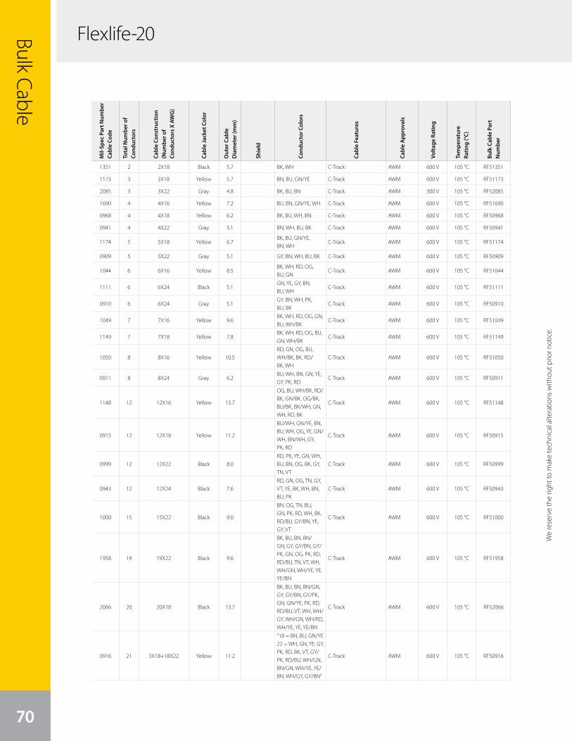
Flexlife-20Bulk Cable
70
We
rese
rve
the
right
to m
ake
tech
nica
l alte
ratio
ns w
ithou
t prio
r not
ice.
Mil-
Spec
Par
t Num
ber
Cabl
e Co
de
Tota
l Num
ber o
f Co
nduc
tors
Cabl
e Co
nstr
uctio
n (N
umbe
r of
Cond
ucto
rs X
AW
G)
Cabl
e Ja
cket
Col
or
Out
er C
able
D
iam
eter
(mm
)
Shie
ld
Cond
ucto
r Col
ors
Cabl
e Fe
atur
es
Cabl
e A
ppro
vals
Volta
ge R
atin
g
Tem
pera
ture
Ra
ting
(°C)
Bulk
Cab
le P
art
Num
ber
1351 2 2X18 Black 5.7 BK, WH C-Track AWM 600 V 105 °C RF51351
1173 3 3X18 Yellow 5.7 BN, BU, GN/YE C-Track AWM 600 V 105 °C RF51173
2085 3 3X22 Gray 4.8 BK, BU, BN C-Track AWM 300 V 105 °C RF52085
1690 4 4X16 Yellow 7.2 BU, BN, GN/YE, WH C-Track AWM 600 V 105 °C RF51690
0968 4 4X18 Yellow 6.2 BK, BU, WH, BN C-Track AWM 600 V 105 °C RF50968
0941 4 4X22 Gray 5.1 BN, WH, BU, BK C-Track AWM 600 V 105 °C RF50941
1174 5 5X18 Yellow 6.7BK, BU, GN/YE, BN, WH
C-Track AWM 600 V 105 °C RF51174
0909 5 5X22 Gray 5.1 GY, BN, WH, BU, BK C-Track AWM 600 V 105 °C RF50909
1044 6 6X16 Yellow 8.5BK, WH, RD, OG, BU, GN
C-Track AWM 600 V 105 °C RF51044
1111 6 6X24 Black 5.1GN, YE, GY, BN, BU, WH
C-Track AWM 600 V 105 °C RF51111
0910 6 6X24 Gray 5.1GY, BN, WH, PK, BU, BK
C-Track AWM 600 V 105 °C RF50910
1049 7 7X16 Yellow 9.6BK, WH, RD, OG, GN, BU, WH/BK
C-Track AWM 600 V 105 °C RF51049
1149 7 7X18 Yellow 7.8BK, WH, RD, OG, BU, GN, WH/BK
C-Track AWM 600 V 105 °C RF51149
1050 8 8X16 Yellow 10.5RD, GN, OG, BU, WH/BK, BK, RD/BK, WH
C-Track AWM 600 V 105 °C RF51050
0911 8 8X24 Gray 6.2BU, WH, BN, GN, YE, GY, PK, RD
C-Track AWM 600 V 105 °C RF50911
1148 12 12X16 Yellow 13.7
OG, BU, WH/BK, RD/BK, GN/BK, OG/BK, BU/BK, BK/WH, GN, WH, RD, BK
C-Track AWM 600 V 105 °C RF51148
0915 12 12X18 Yellow 11.2
BU/WH, GN/YE, BN, BU, WH, OG, YE, GN/WH, BN/WH, GY, PK, RD
C-Track AWM 600 V 105 °C RF50915
0999 12 12X22 Black 8.0RD, PK, YE, GN, WH, BU, BN, OG, BK, GY, TN, VT
C-Track AWM 600 V 105 °C RF50999
0943 12 12X24 Black 7.6RD, GN, OG, TN, GY, VT, YE, BK, WH, BN, BU, PK
C-Track AWM 600 V 105 °C RF50943
1000 15 15X22 Black 9.0
BN, OG, TN, BU, GN, PK, RD, WH, BK, RD/BU, GY/BN, YE, GY, VT
C-Track AWM 600 V 105 °C RF51000
1958 19 19X22 Black 9.6
BK, BU, BN, BN/GN, GY, GY/BN, GY/PK, GN, OG, PK, RD, RD/BU, TN, VT, WH, WH/GN, WH/YE, YE, YE/BN
C-Track AWM 600 V 105 °C RF51958
2066 20 20X18 Black 13.7
BK, BU, BN, BN/GN, GY, GY/BN, GY/PK, GN, GN/YE, PK, RD, RD/BU, VT, WH, WH/GY, WH/GN, WH/RD, WH/YE, YE, YE/BN
C-Track AWM 600 V 105 °C RF52066
0916 21 3X18+18X22 Yellow 11.2
"18 = BN, BU, GN/YE22 = WH, GN, YE, GY, PK, RD, BK, VT, GY/PK, RD/BU, WH/GN, BN/GN, WH/YE, YE/BN, WH/GY, GY/BN”
C-Track AWM 600 V 105 °C RF50916
We reserve the right to m
ake technical alterations without prior notice.
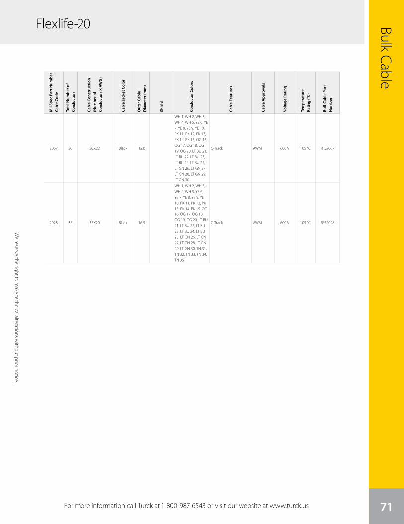
We
rese
rve
the
right
to m
ake
tech
nica
l alte
ratio
ns w
ithou
t prio
r not
ice.
Bulk Cable
71
Flexlife-20
For more information call Turck at 1-800-987-6543 or visit our website at www.turck.us
We reserve the right to m
ake technical alterations without prior notice.
Mil-
Spec
Par
t Num
ber
Cabl
e Co
de
Tota
l Num
ber o
f Co
nduc
tors
Cabl
e Co
nstr
uctio
n (N
umbe
r of
Cond
ucto
rs X
AW
G)
Cabl
e Ja
cket
Col
or
Out
er C
able
D
iam
eter
(mm
)
Shie
ld
Cond
ucto
r Col
ors
Cabl
e Fe
atur
es
Cabl
e A
ppro
vals
Volta
ge R
atin
g
Tem
pera
ture
Ra
ting
(°C)
Bulk
Cab
le P
art
Num
ber
2067 30 30X22 Black 12.0
WH 1, WH 2, WH 3, WH 4, WH 5, YE 6, YE 7, YE 8, YE 9, YE 10, PK 11, PK 12, PK 13, PK 14, PK 15, OG 16, OG 17, OG 18, OG 19, OG 20, LT BU 21, LT BU 22, LT BU 23, LT BU 24, LT BU 25, LT GN 26, LT GN 27, LT GN 28, LT GN 29, LT GN 30
C-Track AWM 600 V 105 °C RF52067
2028 35 35X20 Black 16.5
WH 1, WH 2, WH 3, WH 4, WH 5, YE 6, YE 7, YE 8, YE 9, YE 10, PK 11, PK 12, PK 13, PK 14, PK 15, OG 16, OG 17, OG 18, OG 19, OG 20, LT BU 21, LT BU 22, LT BU 23, LT BU 24, LT BU 25, LT GN 26, LT GN 27, LT GN 28, LT GN 29, LT GN 30, TN 31, TN 32, TN 33, TN 34, TN 35
C-Track AWM 600 V 105 °C RF52028
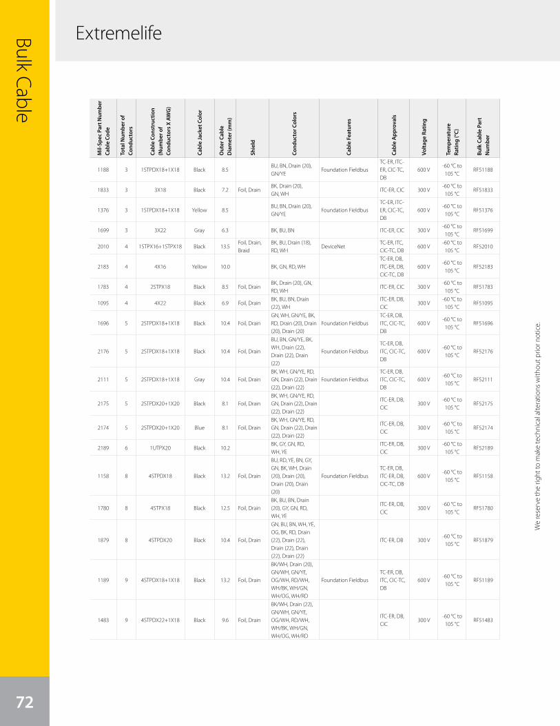
ExtremelifeBulk Cable
72
We
rese
rve
the
right
to m
ake
tech
nica
l alte
ratio
ns w
ithou
t prio
r not
ice.
Mil-
Spec
Par
t Num
ber
Cabl
e Co
de
Tota
l Num
ber o
f Co
nduc
tors
Cabl
e Co
nstr
uctio
n (N
umbe
r of
Cond
ucto
rs X
AW
G)
Cabl
e Ja
cket
Col
or
Out
er C
able
D
iam
eter
(mm
)
Shie
ld
Cond
ucto
r Col
ors
Cabl
e Fe
atur
es
Cabl
e A
ppro
vals
Volta
ge R
atin
g
Tem
pera
ture
Ra
ting
(°C)
Bulk
Cab
le P
art
Num
ber
1188 3 1STPDX18+1X18 Black 8.5BU, BN, Drain (20), GN/YE
Foundation FieldbusTC-ER, ITC-ER, CIC-TC, DB
600 V-60 °C to 105 °C
RF51188
1833 3 3X18 Black 7.2 Foil, DrainBK, Drain (20), GN, WH
ITC-ER, CIC 300 V-60 °C to 105 °C
RF51833
1376 3 1STPDX18+1X18 Yellow 8.5BU, BN, Drain (20), GN/YE
Foundation FieldbusTC-ER, ITC-ER, CIC-TC, DB
600 V-60 °C to 105 °C
RF51376
1699 3 3X22 Gray 6.3 BK, BU, BN ITC-ER, CIC 300 V-60 °C to 105 °C
RF51699
2010 4 1STPX16+1STPX18 Black 13.5Foil, Drain, Braid
BK, BU, Drain (18), RD, WH
DeviceNetTC-ER, ITC, CIC-TC, DB
600 V-60 °C to 105 °C
RF52010
2183 4 4X16 Yellow 10.0 BK, GN, RD, WHTC-ER, DB, ITC-ER, DB, CIC-TC, DB
600 V-60 °C to 105 °C
RF52183
1783 4 2STPX18 Black 8.5 Foil, DrainBK, Drain (20), GN, RD, WH
ITC-ER, CIC 300 V-60 °C to 105 °C
RF51783
1095 4 4X22 Black 6.9 Foil, DrainBK, BU, BN, Drain (22), WH
ITC-ER, DB, CIC
300 V-60 °C to 105 °C
RF51095
1696 5 2STPDX18+1X18 Black 10.4 Foil, DrainGN, WH, GN/YE, BK, RD, Drain (20), Drain (20), Drain (20)
Foundation FieldbusTC-ER, DB, ITC, CIC-TC, DB
600 V-60 °C to 105 °C
RF51696
2176 5 2STPDX18+1X18 Black 10.4 Foil, Drain
BU, BN, GN/YE, BK, WH, Drain (22), Drain (22), Drain (22)
Foundation FieldbusTC-ER, DB, ITC, CIC-TC, DB
600 V-60 °C to 105 °C
RF52176
2111 5 2STPDX18+1X18 Gray 10.4 Foil, DrainBK, WH, GN/YE, RD, GN, Drain (22), Drain (22), Drain (22)
Foundation FieldbusTC-ER, DB, ITC, CIC-TC, DB
600 V-60 °C to 105 °C
RF52111
2175 5 2STPDX20+1X20 Black 8.1 Foil, DrainBK, WH, GN/YE, RD, GN, Drain (22), Drain (22), Drain (22)
ITC-ER, DB, CIC
300 V-60 °C to 105 °C
RF52175
2174 5 2STPDX20+1X20 Blue 8.1 Foil, DrainBK, WH, GN/YE, RD, GN, Drain (22), Drain (22), Drain (22)
ITC-ER, DB, CIC
300 V-60 °C to 105 °C
RF52174
2189 6 1UTPX20 Black 10.2BK, GY, GN, RD, WH, YE
ITC-ER, DB, CIC
300 V-60 °C to 105 °C
RF52189
1158 8 4STPDX18 Black 13.2 Foil, Drain
BU, RD, YE, BN, GY, GN, BK, WH, Drain (20), Drain (20), Drain (20), Drain (20)
Foundation FieldbusTC-ER, DB, ITC-ER, DB, CIC-TC, DB
600 V-60 °C to 105 °C
RF51158
1780 8 4STPX18 Black 12.5 Foil, DrainBK, BU, BN, Drain (20), GY, GN, RD, WH, YE
ITC-ER, DB, CIC
300 V-60 °C to 105 °C
RF51780
1879 8 4STPDX20 Black 10.4 Foil, Drain
GN, BU, BN, WH, YE, OG, BK, RD, Drain (22), Drain (22), Drain (22), Drain (22), Drain (22)
ITC-ER, DB 300 V-60 °C to 105 °C
RF51879
1189 9 4STPDX18+1X18 Black 13.2 Foil, Drain
BK/WH, Drain (20), GN/WH, GN/YE, OG/WH, RD/WH, WH/BK, WH/GN, WH/OG, WH/RD
Foundation FieldbusTC-ER, DB, ITC, CIC-TC, DB
600 V-60 °C to 105 °C
RF51189
1483 9 4STPDX22+1X18 Black 9.6 Foil, Drain
BK/WH, Drain (22), GN/WH, GN/YE, OG/WH, RD/WH, WH/BK, WH/GN, WH/OG, WH/RD
ITC-ER, DB, CIC
300 V-60 °C to 105 °C
RF51483
We reserve the right to m
ake technical alterations without prior notice.
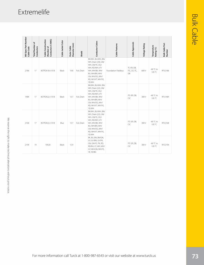
We
rese
rve
the
right
to m
ake
tech
nica
l alte
ratio
ns w
ithou
t prio
r not
ice.
Bulk Cable
73
Extremelife
For more information call Turck at 1-800-987-6543 or visit our website at www.turck.us
We reserve the right to m
ake technical alterations without prior notice.
Mil-
Spec
Par
t Num
ber
Cabl
e Co
de
Tota
l Num
ber o
f Co
nduc
tors
Cabl
e Co
nstr
uctio
n (N
umbe
r of
Cond
ucto
rs X
AW
G)
Cabl
e Ja
cket
Col
or
Out
er C
able
D
iam
eter
(mm
)
Shie
ld
Cond
ucto
r Col
ors
Cabl
e Fe
atur
es
Cabl
e A
ppro
vals
Volta
ge R
atin
g
Tem
pera
ture
Ra
ting
(°C)
Bulk
Cab
le P
art
Num
ber
2186 17 8STPDX18+1X18 Black 19.8 Foil, Drain
BK/WH, BU/WH, BN/WH, Drain (20), GN/WH, GN/YE, OG/WH, RD/WH, VT/WH, WH/BK, WH/BU, WH/BN, WH/GN, WH/OG, WH/RD, WH/VT, WH/YE, YE/WH
Foundation FieldbusTC-ER, DB, ITC, CIC-TC, DB
600 V-60 °C to 105 °C
RF52186
1484 17 8STPDX22+1X18 Black 13.7 Foil, Drain
BK/WH, BU/WH, BN/WH, Drain (22), GN/WH, GN/YE, OG/WH, RD/WH, VT/WH, WH/BK, WH/BU, WH/BN, WH/GN, WH/OG, WH/RD, WH/VT, WH/YE, YE/WH
ITC-ER, DB, CIC
300 V-60 °C to 105 °C
RF51484
2168 17 8STPDX22+1X18 Blue 13.7 Foil, Drain
BK/WH, BU/WH, BN/WH, Drain (22), GN/WH, GN/YE, OG/WH, RD/WH, VT/WH, WH/BK, WH/BU, WH/BN, WH/GN, WH/OG, WH/RD, WH/VT, WH/YE, YE/WH
ITC-ER, DB, CIC
300 V-60 °C to 105 °C
RF52168
2194 19 19X20 Black 15.9
BK, BU, BN, BN/GN, GY, GY/BN, GY/PK, GN, GN/YE, PK, RD, RD/BU, VT, WH, WH/GY, WH/GN, WH/YE, YE, YE/BN
ITC-ER, DB, CIC
300 V-60 °C to 105 °C
RF52194
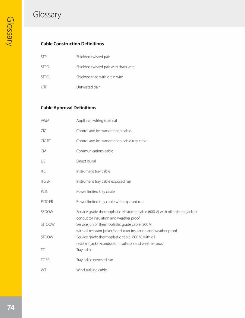
Glossary
74
Glossary
Cable Construction Definitions
STP Shielded twisted pair
STPD Shielded twisted pair with drain wire
STRD Shielded triad with drain wire
UTP Untwisted pair
Cable Approval Definitions
AWM Appliance wiring material
CIC Control and instrumentation cable
CIC-TC Control and instrumentation cable tray cable
CM Communications cable
DB Direct burial
ITC Instrument tray cable
ITC-ER Instrument tray cable exposed run
PLTC Power limited tray cable
PLTC-ER Power limited tray cable with exposed run
SEOOW Service grade thermoplastic elastomer cable (600 V) with oil resistant jacket/
conductor insulation and weather proof
SJTOOW Service junior thermoplastic grade cable (300 V)
with oil resistant jacket/conductor insulation and weather proof
STOOW Service grade thermoplastic cable (600 V) with oil
resistant jacket/conductor insulation and weather proof
TC Tray cable
TC-ER Tray cable exposed run
WT Wind turbine cable

Notes
75
Notes

76
RISK OF LOSS
Delivery of the equipment to a common carrier shall constitute delivery to the Purchaser and the risk of loss shall transfer at that time to Purchaser. Should delivery be delayed due to an act or omission on the part of the Purchaser, risk of loss shall transfer to the Purchaser upon notification by Turck Inc. that the order is complete and ready for shipment.
WARRANTIES
Turck Inc. (hereinafter “Turck”) offers five (5) WARRANTIES to cover all products sold. They are as follows:1) The 12-MONTH WARRANTY is available for the products listed - generally those not covered by
LIFETIME, 5-YEAR, 24-MONTH or 18-MONTH warranty. No registration required.2) The 18-MONTH WARRANTY is available for the products listed - generally those not covered by
LIFETIME or 5-YEAR WARRANTY. No registration is required.3) The 24-MONTH WARRANTY is available for the products listed - generally those not covered by
LIFETIME, 5-YEAR or 18-MONTH. No registration is required.4) The 5-YEAR WARRANTY is available generally for the products listed. No registration is required.5) A LIFETIME WARRANTY is available for the products listed. It becomes effective when the accompanying
TURCK LIFETIME WARRANTY REGISTRATION is completed and returned to Turck.
GENERAL TERMS AND CONDITIONS FOR ALL WARRANTIES
• 12-MONTH STANDARD WARRANTY• 18-MONTH STANDARD WARRANTY• 24-MONTH STANDARD WARRANTY• 5-YEAR WARRANTY• LIFETIME WARRANTY
Turck warrants the Products covered by the respective WARRANTY AGREEMENTS to be free from defects in material and workmanship under normal and proper usage for the respective time periods listed above from the date of shipment from Turck. In addition, certain specific terms apply to the various WARRANTIES.
THESE EXPRESS WARRANTIES ARE IN LIEU OF AND EXCLUDE ALL OTHER REPRESENTATIONS MADE - BOTH EXPRESSED AND IMPLIED. THERE ARE NO WARRANTIES OF MERCHANTABILITY OR OF FITNESS FOR A PARTICULAR PURPOSE FOR PRODUCTS COVERED BY THESE TERMS AND CONDITIONS.
Turck warrants that the goods sold are as described, but no promise, description, affirmation of fact, sample model or representation, oral or written shall be part of an order, unless set forth in these terms and conditions, or are in writing and signed by an authorized representative of Turck. These WARRANTIES do not apply to any Product which has been subject to misuse, negligence, or accident - or to any Product which has been modified or repaired, improperly installed, altered, or disassembled - except according to Turck’s written instructions.
These WARRANTIES are subject to the following conditions:1) These WARRANTIES are limited to the electronic and mechanical performance only, as
expressly detailed in the Product specifications and NOT to cosmetic performance.2) These WARRANTIES shall not apply to any cables attached to, or integrated with the Product.
However, the 18-MONTH WARRANTY shall apply to cables sold separately by Turck.3) These WARRANTIES shall not apply to any Products which are stored, or utilized, in harsh
environmental or electrical conditions outside Turck’s written specifications.4) The WARRANTIES are applicable only to Products shipped from Turck subsequent
to January 1, 1988.
ADDITIONAL SPECIFIC TERMS FOR:(12-MONTH STANDARD WARRANTY) for Linear Displacement Transducers, EZ Track, RFID Products, Draw Wire Assemblies and Slip Rings.
(18-MONTH STANDARD WARRANTY) FOR Q-TRACK INDUCTIVE SENSORS, ULTRASONIC SENSORS, FLOW SENSORS, PRESSURE SENSORS, TEMPERATURE SENSORS, INCLINOMETERS, CABLES AND ALL NON-SENSING PRODUCTS SOLD BY TURCK INC. INCLUDING MULTI-SAFE, MULTI-MODUL, MULTI-CART AND RELATED AMPLIFIER PRODUCTS, RELAYS AND TIMERS.
(24-MONTH STANDARD WARRANTY) FOR ENCODERS excluding Draw Wire Assemblies.
5-YEAR WARRANTY FOR INDUCTIVE AND CAPACITIVE PROXIMITY SENSORS: The periods covered for the above WARRANTIES and Products shall be 12 MONTHS, 18-MONTHS, 24-MONTHS and 5-YEARS, respectively, from the date of shipment from Turck.
LIFETIME WARRANTY (OPTIONAL - REGISTRATION REQUIRED) FOR INDUCTIVE, INDUCTIVE MAGNET OPERATED AND CAPACITIVE PROXIMITY SENSORS SOLD TO THE ORIGINAL PURCHASER FOR THE LIFETIME OF THE ORIGINAL APPLICATION.
Warranty Terms and Conditions

77
THE FOLLOWING TERMS APPLY TO THE LIFETIME WARRANTY IN ADDITION TO THE GENERAL TERMS:
1) This WARRANTY shall be effective only when the LIFETIME WARRANTY REGISTRATION has been completed, signed by the End User and an authorized Turck Representative or Distributor and has been received by Turck no later than six (6) months after installation in the End User’s Plant, or two (2) years from the date product was shipped from Turck, whichever is sooner.
2) This warranty is available only to Turck’s authorized Representatives, Distributors and to the Original User. (The term “Original User” means that person, firm, or corporation which first uses the Product on a continuous basis in connection with the operation of a production line, piece of machinery, equipment, or similar device.) In the event the ownership of the product is transferred to a person, firm or corporation other than the Original User, this WARRANTY shall terminate.
3) This WARRANTY is applicable only to the Original Application. In the event the machinery, equipment, or production line to which the Product is connected, or on which it is installed, is substituted, changed, moved or replaced, the WARRANTY shall terminate.
4) This WARRANTY shall be valid only if the Product was purchased by the Original User from Turck, or from an authorized Turck Distributor, or was an integral part of a piece of machinery and equipment obtained by the Original user from an Original Equipment Manufacturer, which itself, was purchased directly from Turck or from an authorized Distributor.
PURCHASER’S REMEDIES
This Remedy shall apply to all WARRANTIES. If a Turck Distributor desires to make a WARRANTY Claim, the Distributor shall, if requested by Turck, ship the Product to Turck’s factory in Minneapolis, Minnesota, postage or freight prepaid. If the User desires to make a WARRANTY Claim, they shall notify the authorized Turck Distributor from whom it was purchased or, if such Distributor is unknown, shall notify Turck. Turck shall, at its option, take any of the following two courses of action for any products which Turck determines are defective in materials or workmanship.
1) Repair or replace the Product and ship the Product to the Original Purchaser or to the authorized Turck Distributor, postage or freight prepaid; or
2) Repay to the Original Purchaser that price paid by the Original Purchaser; provided that if the claim is made under the LIFETIME WARRANTY, and such Product is not then being manufactured by Turck, then the amount to be repaid by Turck to the Original Purchaser shall be reduced according to the following schedule:
Number of Years Since Date Percent of Original Purchase of Purchase by Original Purchaser Price To Be Paid by Turck 10 50% 15 25% 20 10% More than 20 5%
PURCHASER’S REMEDIES SHALL BE LIMITED EXCLUSIVELY TO THE RIGHT OF REPLACEMENT, REPAIR OR REPAYMENT AS PROVIDED AND DOES NOT INCLUDE ANY LABOR COST OR REPLACEMENT AT ORIGINAL PURCHASER’S SITE. TURCK SHALL NOT BE LIABLE FORANY CONSEQUENTIAL DAMAGES RESULTING FROM ANY BREACH OF ANY WARRANTY, EXPRESSED OR IMPLIED, APPLICABLE TO THE PRODUCT, INCLUDING WITHOUT LIMITATION, ANY DAMAGES RESULTING FROM PROPERTY DAMAGE, PERSONAL INJURY OR BUSINESS INTERRUPTION.
CONSIDER SAFETY AND PROTECTION PRECAUTIONS
Turck takes great care to design and build reliable and dependable products, however, some products can fail eventually. You must take precautions to design your equipment to prevent property damage and personal injury in the unlikely event of failure. As a matter of policy, Turck does NOT recommend the installation of electronic controls as the sole device FOR THE PROTECTION OF PERSONNEL in connection with power driven presses, brakes, shears and similar equipment and, therefore, the customer should build in redundancy or dual control using approved safety devices for these applications.


Turck Inc. sells its products through Authorized Distributors. These distributors provide our customers with technical support, service and local stock. Turck
distributors are located nationwide – including all major metropolitan marketing areas.
For Application Assistance or for the location
of your nearest Turck distributor, call:
1-800-544-7769
Specifications in this manual are subject to change with out notice. Turck also reserves the right to make
modifications and makes no guarantee of the accuracy of the information contained herein.
Literature and Media questions or concerns?Contact Turck USA Marketing – [email protected]

28 subsidiaries and over 60 representations worldwide!
www.turck.comB2406 A 02/16©2016 by Turck Inc. All rights reserved. No part of the
publication may be reproduced without written permission.
Printed in USA


