MIL-PRF-8805F SUPERSEDING MIL-PRF-8805F …everyspec.com/MIL-PRF/MIL-PRF-000100-09999/... ·...
55
Comments, suggestions or questions on this document should be addressed to Defense Supply Center Columbus, ATTN: VAT, Post Office Box 3990, Columbus, OH 43218-3990, or emailed to [email protected] . Since contact information can change, you may want to verify the currency of this address information using the ASSIST Online database at https://assist.daps.dla.mil/ . AMSC N/A FSC 5930 INCH-POUND MIL-PRF-8805F w/Amendment 3 14 June 2010 SUPERSEDING MIL-PRF-8805F w/Amendment 2 27 April 2009 PERFORMANCE SPECIFICATION SWITCHES AND SWITCH ASSEMBLIES, SENSITIVE, SNAP ACTION (BASIC, LIMIT, PUSH BUTTON AND TOGGLE SWITCHES), GENERAL SPECIFICATION FOR This specification is approved for use by all Departments and Agencies of the Department of Defense. 1. SCOPE 1.1 Scope . This specification covers the general requirements for snap action sensitive switches and switch assemblies. The sensitive switch assemblies include limit, push-button, and toggle operated types. The term switches includes switch assemblies, see 6.5.19 . For intended use and application see 6.1 . For definitions of terms used in this specification, see 6.5. 1.2 Classification . 1.2.1 Enclosure requirement . The enclosure requirement is identified by a single digit in accordance with table I. TABLE I. Enclosure requirement (see 6.5.9) . Symbol Seal 1 2 3 4 5 6 Unsealed Dusttight Watertight Resilient Hermetic Splashproof 1.2.2 Temperature characteristic . The temperature characteristic is identified by a single digit, indicating the temperature range of the switch, in accordance with table II. Downloaded from http://www.everyspec.com
Transcript of MIL-PRF-8805F SUPERSEDING MIL-PRF-8805F …everyspec.com/MIL-PRF/MIL-PRF-000100-09999/... ·...
Comments, suggestions or questions on this document should be addressed to Defense Supply Center Columbus, ATTN: VAT, Post Office Box 3990, Columbus, OH 43218-3990, or emailed to [email protected]. Since contact information can change, you may want to verify the currency of this address information using the ASSIST Online database at https://assist.daps.dla.mil/. AMSC N/A FSC 5930
INCH-POUND MIL-PRF-8805F w/Amendment 3 14 June 2010 SUPERSEDING MIL-PRF-8805F w/Amendment 2 27 April 2009
PERFORMANCE SPECIFICATION
SWITCHES AND SWITCH ASSEMBLIES, SENSITIVE, SNAP ACTION (BASIC, LIMIT, PUSH BUTTON AND TOGGLE SWITCHES), GENERAL SPECIFICATION FOR
This specification is approved for use by all Departments and Agencies of the Department of Defense.
1. SCOPE
1.1 Scope. This specification covers the general requirements for snap action sensitive switches and switch assemblies. The sensitive switch assemblies include limit, push-button, and toggle operated types. The term switches includes switch assemblies, see 6.5.19. For intended use and application see 6.1. For definitions of terms used in this specification, see 6.5.
1.2 Classification.
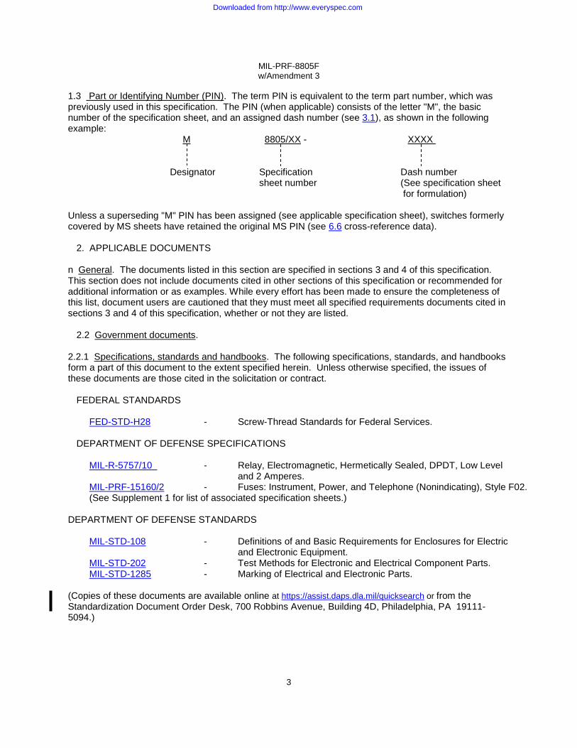
1.2.1 Enclosure requirement. The enclosure requirement is identified by a single digit in accordance with table I.
TABLE I. Enclosure requirement (see 6.5.9).
Symbol
Seal
1 2 3 4 5 6
Unsealed Dusttight
Watertight Resilient Hermetic
Splashproof
1.2.2 Temperature characteristic. The temperature characteristic is identified by a single digit, indicating the temperature range of the switch, in accordance with table II.
Downloaded from http://www.everyspec.com

MIL-PRF-8805F w/Amendment 3
2
TABLE II. Temperature characteristic.
Symbol Temperature range
Minimum Maximum
1 2 3 4
-55°C -65°C -65°C -65°C
+85°C +125°C +200°C +350°C
1.2.3 Shock type. The shock type is identified by a single letter in accordance with table III.
TABLE III. Shock type.
Symbol Shock type
M
H
100 g (sawtooth), test condition I, method 213 of MIL-STD-202 High impact
1.2.4 Sinusoidal vibration grade. The vibration grade is identified by a single digit in accordance with
table IV. TABLE IV. Sinusoidal vibration grade.
Symbol
Frequency range Acceleration level
1 2 3
Hertz
10 - 500 swept sinusoidal 10 - 2,000 swept sinusoidal 10 - 3,000 swept sinusoidal
10 g peak 15 g peak 30 g peak
1.2.5 Random vibration category (when specified, see 3.1). The random vibration category is identified by a single digit in accordance with table V. TABLE V. Random vibration categories.
Symbol
Power spectral
density
Overall RMS g
Frequency range (Hz)
A B C D E F
.02 .04 .06 .1 .2 .3
5.35 7.56 9.26 11.95 16.91 20.71
50 - 2,000 50 - 2,000 50 - 2,000 50 - 2,000 50 - 2,000 50 - 2,000
Downloaded from http://www.everyspec.com
MIL-PRF-8805F w/Amendment 3
3
1.3 Part or Identifying Number (PIN). The term PIN is equivalent to the term part number, which was previously used in this specification. The PIN (when applicable) consists of the letter "M", the basic number of the specification sheet, and an assigned dash number (see 3.1), as shown in the following example:
M 8805/XX - XXXX
Designator Specification Dash number sheet number (See specification sheet for formulation) Unless a superseding "M" PIN has been assigned (see applicable specification sheet), switches formerly covered by MS sheets have retained the original MS PIN (see 6.6 cross-reference data).
2. APPLICABLE DOCUMENTS
n General. The documents listed in this section are specified in sections 3 and 4 of this specification. This section does not include documents cited in other sections of this specification or recommended for additional information or as examples. While every effort has been made to ensure the completeness of this list, document users are cautioned that they must meet all specified requirements documents cited in sections 3 and 4 of this specification, whether or not they are listed.
2.2 Government documents.
2.2.1 Specifications, standards and handbooks. The following specifications, standards, and handbooks form a part of this document to the extent specified herein. Unless otherwise specified, the issues of these documents are those cited in the solicitation or contract. FEDERAL STANDARDS
FED-STD-H28 - Screw-Thread Standards for Federal Services.
DEPARTMENT OF DEFENSE SPECIFICATIONS
MIL-R-5757/10 - Relay, Electromagnetic, Hermetically Sealed, DPDT, Low Level and 2 Amperes.
MIL-PRF-15160/2 - Fuses: Instrument, Power, and Telephone (Nonindicating), Style F02. (See Supplement 1 for list of associated specification sheets.)
DEPARTMENT OF DEFENSE STANDARDS
MIL-STD-108 - Definitions of and Basic Requirements for Enclosures for Electric
and Electronic Equipment. MIL-STD-202 - Test Methods for Electronic and Electrical Component Parts. MIL-STD-1285 - Marking of Electrical and Electronic Parts.
(Copies of these documents are available online at https://assist.daps.dla.mil/quicksearch or from the
Standardization Document Order Desk, 700 Robbins Avenue, Building 4D, Philadelphia, PA 19111-5094.)
Downloaded from http://www.everyspec.com

MIL-PRF-8805F w/Amendment 3
4
2.3 Non-Government publications. The following documents form a part of this document to the extent specified herein. Unless otherwise specified, the issues of the documents which are those cited in the solicitation or contract.
AMERICAN NATIONAL STANDARDS INSTITUTE (ANSI)
NCSL Z540.1 - Calibration Laboratories and Measuring and Test Equipment. (Application for copies can be found online at http://www.ansi.org/ or 25 West 43rd Street, New York, NY 10036-8002, telephone 212-642-4900, fax 212-302-1286)
AMERICAN SOCIETY FOR TESTING AND MATERIALS (ASTM International)
ASTM D4066 - Nylon Injection and Extrusion Materials. (Application for copies can be found online at http://www.astm.org/ or should be addressed to the American Society for Testing and Materials, 100 Barr Harbor Drive, P.O.Box C700, West Conshohocken, PA, 19428-2959).
ELECTRONIC INDUSTRIES ASSOCIATION (EIA)
EIA RS448-4 - Standard Test Methods for Electromechanical Switches. EIA448-22 - Resistance to Soldering Heat, Soldering Method
EIA/IPC/ J-STD-002 - Solderability Tests for Component Leads, Terminations, Lugs,
Terminals and Wires. (Application for copies can be found online at http://www.eia.org or should be addressed to EIA Engineering Department, Standards Sales Office, 2500 Wilson Blvd., Arlington, VA 22201-3834.)
INTERNATIONAL ORGANIZATION FOR STANDARDS (ISO)
ISO 10012-1 - Quality Assurance Requirements for Measuring Equipment Part 1; Meteorological Confirmation System for Measuring Equipment
(Application for copies can be found online at http://www.ansi.org or should be addressed to the American National Standards Institute (ANSI), 25 West 43rd Street, New York, NY 10036-8002, telephone 212-642-4900, fax 212-302-1286).
SOCIETY OF AUTOMOTIVE ENGINEERS INTERNATIONAL (SAE) SAE-AS58091 - Circuit Breakers, Trip-Free, Aircraft, General Specification for. SAE-AS7928 - Terminal, Lug Splices, Conductor, Crimp-Style, Copper, General
Specification for. SAE-AS25244 - Circuit Breaker, Trip Free, Push Pull, 5 Thru 50 Ampere, TypeI.
(Application for copies can be found online at http://www.sae.org or should be addressed to the Society Of Automotive Engineers (SAE) World Headquarters, 400 commonwealth Drive, Warrendale, PA 15096-0001)
Downloaded from http://www.everyspec.com

MIL-PRF-8805F w/Amendment 3
5
UNDERWRITERS' LABORATORIES, INC. (UL)
UL94 - Tests for Flammability of Plastic Materials for Parts in Devices and Appliances.
(Application for copies should be addressed to the Underwriters' Laboratories, Inc., 333 Pfingsten Road, Northbrook, IL 60062-2096or online at http://www.ul.com) (Industry association specifications and standards are generally available for reference from libraries. They are also distributed among technical groups and using Federal agencies.)
2.4 Order of precedence. In the event of a conflict between the text of this document and the references
cited herein (except for related specification sheets), the text of this document takes precedence. Nothing in this document, however, supersedes applicable laws and regulations unless a specific exemption has been obtained.
3. REQUIREMENTS
3.1 Specification sheets. The individual item requirements shall be as specified herein and in accordance with the applicable specification sheet. In the event of any conflict between the requirements of this specification and the specification sheet, the latter shall govern.
3.2 Switch categories. Switches furnished under this specification shall be category I or II as defined in 3.2.1 and 3.2.2 respectively.
3.2.1 Category I switches. Switches completely defined by a specification sheet (see 3.1). Category I switches shall be ordered in accordance with 6.2.1.
3.2.2 Category II switches. Switches the same as category I switches except for minor differences which do not change the basic materials, design or construction of the qualified switch, and which do not effect performance. Unless otherwise specified (see 3.1), these variations are limited to the addition of legends; variation in size, shape or dimensions of terminations; selected switches with tighter tolerances on operating characteristics; and variations in color of operating buttons or levers, bezels, mounting flanges, barriers, and mounting bushings. Category II switches shall be acquired from a source listed on the applicable qualified products list for the particular similar product in category I. Category II switches shall be ordered in accordance with 6.2.2. These switches are nonstandard.
3.3 Qualification. Category I switches furnished under this specification shall be products that are manufactured by a manufacturer authorized by the qualifying activity for listing on the applicable qualified products list before contract award. (See 4.4 and 6.3).
3.4 Material. Material shall be as specified herein. However, when a definite material is not specified, a material shall be used which will enable the switches to meet the performance requirements of this specification. Acceptance or approval of any constituent material shall not be construed as a guaranty of the acceptance of the finished product.
3.4.1 Metals. All metal parts, other than current-carrying parts, shall be of corrosion-resistant material
or shall be suitably protected to resist corrosion.
3.4.1.1 Ferrous material. Ferrous material shall not be used for current-carrying parts except for feed-through terminals in headers and for switches having temperature characteristics with a maximum temperature rating of 125°C or higher.
Downloaded from http://www.everyspec.com
MIL-PRF-8805F w/Amendment 3
6
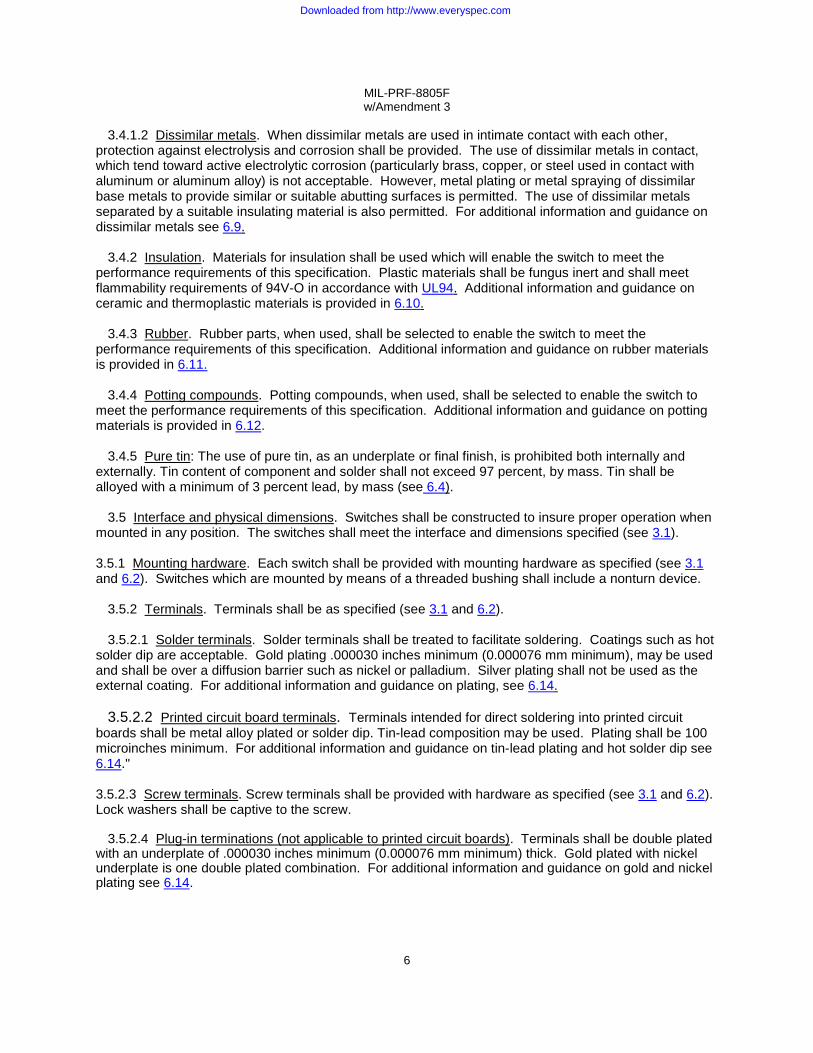
3.4.1.2 Dissimilar metals. When dissimilar metals are used in intimate contact with each other, protection against electrolysis and corrosion shall be provided. The use of dissimilar metals in contact, which tend toward active electrolytic corrosion (particularly brass, copper, or steel used in contact with aluminum or aluminum alloy) is not acceptable. However, metal plating or metal spraying of dissimilar base metals to provide similar or suitable abutting surfaces is permitted. The use of dissimilar metals separated by a suitable insulating material is also permitted. For additional information and guidance on dissimilar metals see 6.9. 3.4.2 Insulation. Materials for insulation shall be used which will enable the switch to meet the performance requirements of this specification. Plastic materials shall be fungus inert and shall meet flammability requirements of 94V-O in accordance with UL94. Additional information and guidance on ceramic and thermoplastic materials is provided in 6.10.
3.4.3 Rubber. Rubber parts, when used, shall be selected to enable the switch to meet the performance requirements of this specification. Additional information and guidance on rubber materials is provided in 6.11.
3.4.4 Potting compounds. Potting compounds, when used, shall be selected to enable the switch to meet the performance requirements of this specification. Additional information and guidance on potting materials is provided in 6.12.
3.4.5 Pure tin: The use of pure tin, as an underplate or final finish, is prohibited both internally and
externally. Tin content of component and solder shall not exceed 97 percent, by mass. Tin shall be alloyed with a minimum of 3 percent lead, by mass (see 6.4).
3.5 Interface and physical dimensions. Switches shall be constructed to insure proper operation when mounted in any position. The switches shall meet the interface and dimensions specified (see 3.1).
3.5.1 Mounting hardware. Each switch shall be provided with mounting hardware as specified (see 3.1 and 6.2). Switches which are mounted by means of a threaded bushing shall include a nonturn device.
3.5.2 Terminals. Terminals shall be as specified (see 3.1 and 6.2).
3.5.2.1 Solder terminals. Solder terminals shall be treated to facilitate soldering. Coatings such as hot solder dip are acceptable. Gold plating .000030 inches minimum (0.000076 mm minimum), may be used and shall be over a diffusion barrier such as nickel or palladium. Silver plating shall not be used as the external coating. For additional information and guidance on plating, see 6.14. 3.5.2.2 Printed circuit board terminals. Terminals intended for direct soldering into printed circuit boards shall be metal alloy plated or solder dip. Tin-lead composition may be used. Plating shall be 100 microinches minimum. For additional information and guidance on tin-lead plating and hot solder dip see 6.14."
3.5.2.3 Screw terminals. Screw terminals shall be provided with hardware as specified (see 3.1 and 6.2). Lock washers shall be captive to the screw. 3.5.2.4 Plug-in terminations (not applicable to printed circuit boards). Terminals shall be double plated with an underplate of .000030 inches minimum (0.000076 mm minimum) thick. Gold plated with nickel underplate is one double plated combination. For additional information and guidance on gold and nickel plating see 6.14.
Downloaded from http://www.everyspec.com

MIL-PRF-8805F w/Amendment 3
7
3.5.3 Screw threads. Screw threads on removable threaded parts shall be in accordance with the unified thread series of FED-STD-H28 or equivalent industry standard. All threaded parts shall engage by at least two full threads. Threading of nonmetallic parts is not be permitted.
n Weight. The weight shall be as specified (see 3.1 and 6.2).
3.6 Solderability (applicable to solderable terminations). When switches are tested as specified in 4.7.2,
the criteria for acceptable solderability shall be in accordance with EIA/IPC/J-STD-002. 3.7 Seal.
3.7.1 Dusttight (applicable to enclosure requirement 2). When switches are tested as specified in
4.7.3.1, the switches shall be mechanically and electrically operative at the conclusion of the test, and there shall be no dust inside the switch.
3.7.2 Watertight (applicable to enclosure requirement 3). When switches are tested as specified in 4.7.3.2, there shall be no leakage as indicated by a continuous stream of the bubbles coming from within the switch enclosure. At the conclusion of the test, switches shall meet the dielectric withstanding voltage requirements as specified in 3.8.
3.7.3 Resilient (applicable to enclosure requirement 4). When switches are tested as specified in 4.7.3.3, the equivalent standard leakage rate shall not exceed 1 x 10⁻⁶ standard atmosphere cubic centimeters per second (atm cm3/s).
3.7.4 Hermetic (applicable to enclosure requirement 5). When switches are tested as specified in 4.7.3.4, the equivalent standard leakage rate shall not exceed 1 x 10⁻⁸ standard atmosphere cubic centimeters per second (atm cm3/s).
3.7.5 Splashproof (applicable to enclosure requirement 6). When switches are tested as specified in 4.7.3.5, there shall be no leakage of water through the panel seal or into the switch as determined by visual inspection. At the conclusion of the test, switches shall meet the dielectric withstanding voltage requirements as specified in 3.8.
3.8 Dielectric withstanding voltage. When switches are tested as specified in 4.7.4, there shall be no
flashover, arcing, or current flow in excess of 500 microamperes.
3.9 Insulation resistance. When switches are tested as specified in 4.7.5, the insulation resistance shall be not less than 1,000 megohms.
3.10 Contact resistance. When measured as specified in 4.7.6, the contact resistance shall not exceed
25 milliohms initially and 40 milliohms after the mechanical endurance test. After electrical endurance, the contact resistance shall not exceed 1 percent of the load impedance using the electrical parameters of the electrical endurance test load. For switches with integral lead wires, the contact resistance shall be as specified (see 3.1).
3.11 Operating characteristics. When switches are tested as specified in 4.7.7, the operating characteristics shall be as specified (see 3.1 and 6.2). Unless otherwise specified (see 3.1 and 6.2), switch action for each individual pole shall be momentary, break-before-make.
3.11.1 Coincidence of operating and releasing points (applicable to multipole switches only). When switches are tested as specified in 4.7.7.1, all poles shall have actuated (transfer of contacts) within the limits specified (see 3.1).
Downloaded from http://www.everyspec.com
MIL-PRF-8805F w/Amendment 3
8
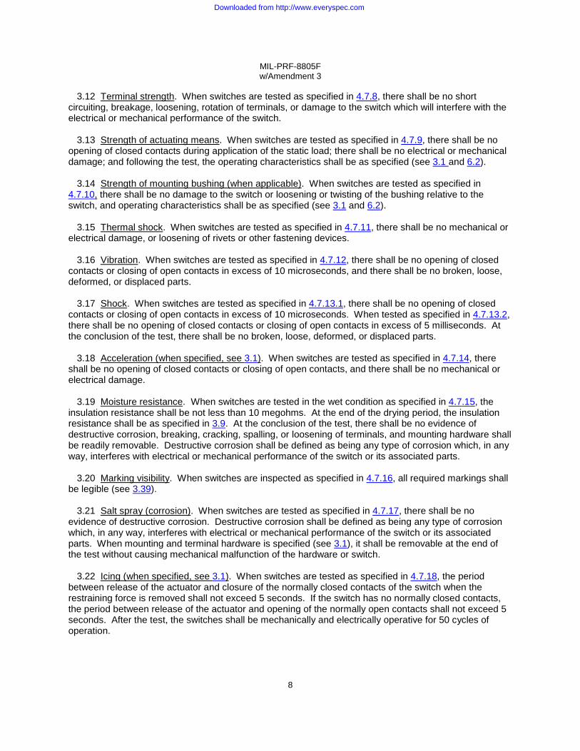
3.12 Terminal strength. When switches are tested as specified in 4.7.8, there shall be no short circuiting, breakage, loosening, rotation of terminals, or damage to the switch which will interfere with the electrical or mechanical performance of the switch.
3.13 Strength of actuating means. When switches are tested as specified in 4.7.9, there shall be no
opening of closed contacts during application of the static load; there shall be no electrical or mechanical damage; and following the test, the operating characteristics shall be as specified (see 3.1 and 6.2).
3.14 Strength of mounting bushing (when applicable). When switches are tested as specified in
4.7.10, there shall be no damage to the switch or loosening or twisting of the bushing relative to the switch, and operating characteristics shall be as specified (see 3.1 and 6.2).
3.15 Thermal shock. When switches are tested as specified in 4.7.11, there shall be no mechanical or electrical damage, or loosening of rivets or other fastening devices.
3.16 Vibration. When switches are tested as specified in 4.7.12, there shall be no opening of closed contacts or closing of open contacts in excess of 10 microseconds, and there shall be no broken, loose, deformed, or displaced parts.
3.17 Shock. When switches are tested as specified in 4.7.13.1, there shall be no opening of closed contacts or closing of open contacts in excess of 10 microseconds. When tested as specified in 4.7.13.2, there shall be no opening of closed contacts or closing of open contacts in excess of 5 milliseconds. At the conclusion of the test, there shall be no broken, loose, deformed, or displaced parts.
3.18 Acceleration (when specified, see 3.1). When switches are tested as specified in 4.7.14, there shall be no opening of closed contacts or closing of open contacts, and there shall be no mechanical or electrical damage.
3.19 Moisture resistance. When switches are tested in the wet condition as specified in 4.7.15, the insulation resistance shall be not less than 10 megohms. At the end of the drying period, the insulation resistance shall be as specified in 3.9. At the conclusion of the test, there shall be no evidence of destructive corrosion, breaking, cracking, spalling, or loosening of terminals, and mounting hardware shall be readily removable. Destructive corrosion shall be defined as being any type of corrosion which, in any way, interferes with electrical or mechanical performance of the switch or its associated parts.
3.20 Marking visibility. When switches are inspected as specified in 4.7.16, all required markings shall be legible (see 3.39).
3.21 Salt spray (corrosion). When switches are tested as specified in 4.7.17, there shall be no evidence of destructive corrosion. Destructive corrosion shall be defined as being any type of corrosion which, in any way, interferes with electrical or mechanical performance of the switch or its associated parts. When mounting and terminal hardware is specified (see 3.1), it shall be removable at the end of the test without causing mechanical malfunction of the hardware or switch.
3.22 Icing (when specified, see 3.1). When switches are tested as specified in 4.7.18, the period between release of the actuator and closure of the normally closed contacts of the switch when the restraining force is removed shall not exceed 5 seconds. If the switch has no normally closed contacts, the period between release of the actuator and opening of the normally open contacts shall not exceed 5 seconds. After the test, the switches shall be mechanically and electrically operative for 50 cycles of operation.
Downloaded from http://www.everyspec.com
MIL-PRF-8805F w/Amendment 3
9
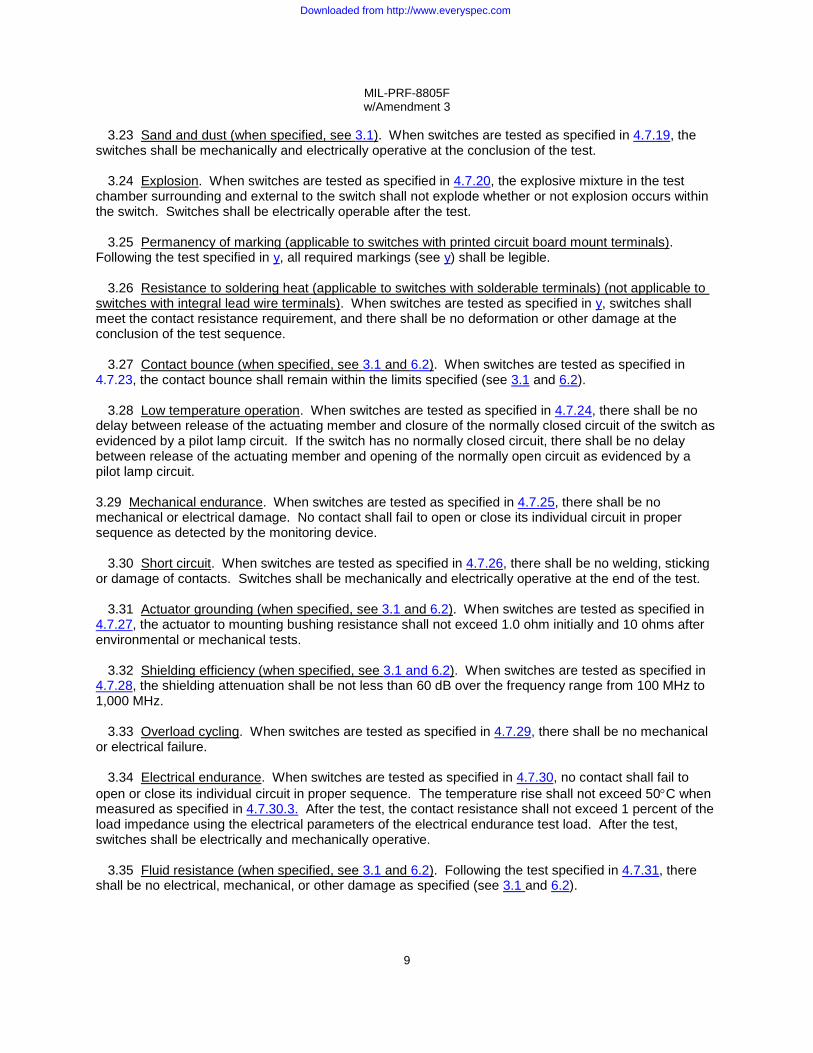
3.23 Sand and dust (when specified, see 3.1). When switches are tested as specified in 4.7.19, the switches shall be mechanically and electrically operative at the conclusion of the test.
3.24 Explosion. When switches are tested as specified in 4.7.20, the explosive mixture in the test
chamber surrounding and external to the switch shall not explode whether or not explosion occurs within the switch. Switches shall be electrically operable after the test.
3.25 Permanency of marking (applicable to switches with printed circuit board mount terminals).
Following the test specified in y, all required markings (see y) shall be legible. 3.26 Resistance to soldering heat (applicable to switches with solderable terminals) (not applicable to
switches with integral lead wire terminals). When switches are tested as specified in y, switches shall meet the contact resistance requirement, and there shall be no deformation or other damage at the conclusion of the test sequence.
3.27 Contact bounce (when specified, see 3.1 and 6.2). When switches are tested as specified in 4.7.23, the contact bounce shall remain within the limits specified (see 3.1 and 6.2).
3.28 Low temperature operation. When switches are tested as specified in 4.7.24, there shall be no delay between release of the actuating member and closure of the normally closed circuit of the switch as evidenced by a pilot lamp circuit. If the switch has no normally closed circuit, there shall be no delay between release of the actuating member and opening of the normally open circuit as evidenced by a pilot lamp circuit.
3.29 Mechanical endurance. When switches are tested as specified in 4.7.25, there shall be no mechanical or electrical damage. No contact shall fail to open or close its individual circuit in proper sequence as detected by the monitoring device.
3.30 Short circuit. When switches are tested as specified in 4.7.26, there shall be no welding, sticking
or damage of contacts. Switches shall be mechanically and electrically operative at the end of the test.
3.31 Actuator grounding (when specified, see 3.1 and 6.2). When switches are tested as specified in 4.7.27, the actuator to mounting bushing resistance shall not exceed 1.0 ohm initially and 10 ohms after environmental or mechanical tests.
3.32 Shielding efficiency (when specified, see 3.1 and 6.2). When switches are tested as specified in
4.7.28, the shielding attenuation shall be not less than 60 dB over the frequency range from 100 MHz to 1,000 MHz.
3.33 Overload cycling. When switches are tested as specified in 4.7.29, there shall be no mechanical or electrical failure. 3.34 Electrical endurance. When switches are tested as specified in 4.7.30, no contact shall fail to open or close its individual circuit in proper sequence. The temperature rise shall not exceed 50°C when measured as specified in 4.7.30.3. After the test, the contact resistance shall not exceed 1 percent of the load impedance using the electrical parameters of the electrical endurance test load. After the test, switches shall be electrically and mechanically operative.
3.35 Fluid resistance (when specified, see 3.1 and 6.2). Following the test specified in 4.7.31, there shall be no electrical, mechanical, or other damage as specified (see 3.1 and 6.2).
Downloaded from http://www.everyspec.com
MIL-PRF-8805F w/Amendment 3
10
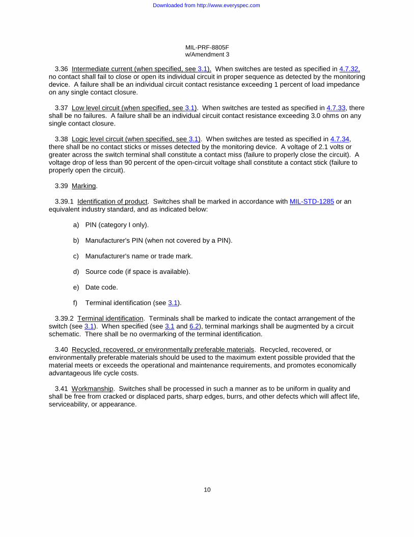
3.36 Intermediate current (when specified, see 3.1). When switches are tested as specified in 4.7.32, no contact shall fail to close or open its individual circuit in proper sequence as detected by the monitoring device. A failure shall be an individual circuit contact resistance exceeding 1 percent of load impedance on any single contact closure.
3.37 Low level circuit (when specified, see 3.1). When switches are tested as specified in 4.7.33, there
shall be no failures. A failure shall be an individual circuit contact resistance exceeding 3.0 ohms on any single contact closure.
3.38 Logic level circuit (when specified, see 3.1). When switches are tested as specified in 4.7.34,
there shall be no contact sticks or misses detected by the monitoring device. A voltage of 2.1 volts or greater across the switch terminal shall constitute a contact miss (failure to properly close the circuit). A voltage drop of less than 90 percent of the open-circuit voltage shall constitute a contact stick (failure to properly open the circuit).
3.39 Marking.
3.39.1 Identification of product. Switches shall be marked in accordance with MIL-STD-1285 or an equivalent industry standard, and as indicated below:
a) PIN (category I only). b) Manufacturer's PIN (when not covered by a PIN). c) Manufacturer's name or trade mark. d) Source code (if space is available). e) Date code. f) Terminal identification (see 3.1).
3.39.2 Terminal identification. Terminals shall be marked to indicate the contact arrangement of the
switch (see 3.1). When specified (see 3.1 and 6.2), terminal markings shall be augmented by a circuit schematic. There shall be no overmarking of the terminal identification.
3.40 Recycled, recovered, or environmentally preferable materials. Recycled, recovered, or environmentally preferable materials should be used to the maximum extent possible provided that the material meets or exceeds the operational and maintenance requirements, and promotes economically advantageous life cycle costs.
3.41 Workmanship. Switches shall be processed in such a manner as to be uniform in quality and shall be free from cracked or displaced parts, sharp edges, burrs, and other defects which will affect life, serviceability, or appearance.
Downloaded from http://www.everyspec.com

MIL-PRF-8805F w/Amendment 3
11
4. VERIFICATION
4.1 Classification of inspections. The inspection requirements specified herein are classified as follows:
a) Qualification inspection (see 4.4). b) Conformance inspection (see 4.5). c) Periodic inspection (see 4.6)
4.2 Test equipment and inspection facilities. Test and measuring equipment and inspection facilities of
sufficient accuracy, quality and quantity to permit performance of the required inspection shall be established and maintained by the contractor. The establishment and maintenance of a calibration system to control the accuracy of the measuring and test equipment shall be in accordance with ANSI/NCSL Z540-1, ISO 10012-1 or approved equivalent.
4.3 Inspection conditions. Unless otherwise specified herein, all inspections shall be performed in accordance with the test conditions specified in the "general requirements" of MIL-STD-202.
4.4 Qualification inspection. Qualification inspection shall be performed at a laboratory acceptable to
the Government (see 6.3) on sample units produced with equipment and procedures normally used in production.
4.4.1 Sample size. The number of switches to be subjected to qualification inspection shall be as specified in table VII. For group submission, the sample submitted shall consist of switches of one basic type as specified on the applicable specification sheet and additional sample units of each of the other types, of the number of varieties specified, and in the quantity specified on the applicable specification sheet.
4.4.2 Inspection routine. Sample units of switches shall be subjected to the qualification inspection in table VII, in the order shown. All sample units shall be subjected to the inspection of group I. The sample units shall then be divided as specified in table VII, group II through group XI as applicable, and subjected to the inspection for their particular group. Any switch failing any inspection shall not be subjected to further inspection.
4.4.3 Failures. One or more failures shall be cause for refusal to grant qualification approval.
4.4.4 Extent of qualification.
4.4.4.1 Single submission. Qualification shall be restricted to the type submitted.
4.4.4.2 Group submission. The extent of qualification shall be in accordance with the applicable specification sheet.
4.4.5 Verification of qualification. Every 12 months, the manufacturer shall provide verification of qualification to the qualifying activity. Continuation is based on meeting the following requirements:
a) Design of switch has not been modified. b) Verification of group A lot acceptance. c) Periodic group B inspection.
4.4.6 Inspection requirements for category II switches. Additional tests to verify suitability of the variations from the category I switches shall be performed as provided (see 6.2.2). Inspection shall be performed by the contractor, after award of contract, and prior to production.
Downloaded from http://www.everyspec.com

MIL-PRF-8805F w/Amendment 3
12
TABLE VII. Qualification inspection.
Inspection Requirement paragraph
Test method paragraph
Group I (all sample units) Visual and mechanical inspection 1/ Seal, watertight (when specified, see 3.1) Seal, resilient (when specified, see 3.1) Seal, hermetic (when specified, see 3.1) Seal, splashproof (when specified, see 3.1) Dielectric withstanding voltage Insulation resistance Contact resistance Operating characteristics Coincidence of operating and releasing points (when applicable) Group II (4 sample units) 3/ 4/ Terminal strength 5/ Strength of actuating means 5/ Strength of mounting bushing (when applicable) 5/ Thermal shock Swept sinusoidal vibration Random vibration (when specified, see 3.1) Shock Acceleration (when specified, see 3.1) Moisture resistance Seal, watertight (when specified, see 3.1) Seal, splashproof (when specified, see 3.1) Dielectric withstanding voltage Operating characteristics Coincidence of operating and releasing points (when applicable) Seal, resilient (when specified, see 3.1) Seal, hermetic (when specified, see 3.1) Marking visibility Group III (2 sample units) Salt spray (except enclosure requirements 1 and 6) Icing (when specified, see 3.1) Dielectric withstanding voltage Insulation resistance Sand and dust (when specified, see 3.1) Operating characteristics Coincidence of operating and releasing points (when applicable) Marking visibility
3.1, 3.4, 3.5, 3.39 and 3.41
3.7.2 3.7.3 3.7.4 3.7.5 3.8 3.9
3.10 3.11
3.11.1
3.12 3.13 3.14 3.15 3.16 3.16 3.17 3.18 3.19 3.7.2 3.7.5 3.8
3.11
3.11.1 3.7.3 3.7.4 3.20
3.21 3.22 3.8 3.9
3.23 3.11
3.11.1 3.20
4.7.1 4.7.3.2 4.7.3.3 4.7.3.4 4.7.3.5 4.7.4 4.7.5 4.7.6 4.7.7
4.7.7.1
4.7.8 4.7.9
4.7.10 4.7.11 4.7.12 4.7.12 4.7.13 4.7.14 4.7.15 4.7.3.2 4.7.3.5 4.7.4 4.7.7
4.7.7.1 4.7.3.3 4.7.3.4 4.7.16
4.7.17 4.7.18 4.7.4 4.7.5
4.7.19 4.7.7
4.7.7.1 4.7.16
See footnotes at end of table
Downloaded from http://www.everyspec.com

MIL-PRF-8805F w/Amendment 3
13
TABLE VII. Qualification inspection - Continued.
Inspection Requirement paragraph
Test method paragraph
Group IV (2 sample units) Salt Spray (enclosure requirements 1 and 6) Marking visibility Group V (2 sample units) Explosion Operating characteristics Coincidence of operating and releasing points (when applicable) Group VI (4 sample units) 4/ Permanency of marking (when applicable) 9/ Resistance to soldering heat (when applicable) Contact resistance Contact bounce (when specified, see 3.1) Low temperature operation 5/ Mechanical endurance at low temperature 5/ 6/ Mechanical endurance at high temperature 5/ Contact resistance Short circuit Dielectric withstanding voltage Operating characteristics Coincidence of operating and releasing points (when applicable) Actuator grounding (when specified, see 3.1) Shielding efficiency (when specified, see 3.1) Group VII (2 sample units for each electrical load, see 3.1) 7/ Overload cycling (all group VII sample units) Electrical endurance 7/ Resistive load, dc Inductive load, dc Motor load, dc Lamp load, dc Resistive load, ac Inductive load, ac Lamp load, ac Motor load, ac Temperature rise Contact resistance Dielectric withstanding voltage 8/ Operating characteristics (all group VII sample units) Coincidence of operating and releasing points (when applicable) (all group VII sample units)
3.21 3.20
3.24 3.11
3.11.1
3.25 3.26 3.10 3.27 3.28 3.29 3.29 3.10 3.30 3.8
3.11
3.11.1 3.31 3.32
3.33 3.34 3.34 3.34 3.34 3.34 3.34 3.34 3.34 3.34 3.34 3.10 3.8
3.11
3.11.1
4.7.17 4.7.16
4.7.20 4.7.7
4.7.7.1
4.7.21 4.7.22 4.7.6
4.7.23 4.7.24 4.7.25 4.7.25 4.7.6
4.7.26 4.7.4 4.7.7
4.7.7.1 4.7.27 4.7.28
4.7.29 4.7.30 4.7.30.2 4.7.30.2 4.7.30.2 4.7.30.2 4.7.30.2 4.7.30.2 4.7.30.2 4.7.30.2 4.7.30.3
4.7.6 4.7.4 4.7.7
4.7.7.1
See footnotes at end of table
Downloaded from http://www.everyspec.com

MIL-PRF-8805F w/Amendment 3
14
TABLE VII. Qualification inspection - Continued.
Inspection Requirement paragraph
Test method paragraph
Group VIII (2 sample units) (enclosure requirements 2, 3, 4, 5, and 6 only) Fluid resistance (when specified, see 3.1) Mechanical endurance at room ambient temperature Operating characteristics Coincidence of operating and releasing points (when applicable) Contact resistance Seal, dusttight (when specified, see 3.1) Seal, watertight (when specified, see 3.1) Seal, resilient (when specified, see 3.1) Seal, hermetic (when specified, see 3.1) Seal, splashproof (when specified, see 3.1) Group IX (2 sample units) Intermediate current (when specified, see 3.1) Operating characteristics Group X (Two sample units for each electrical load) Low level circuit (when specified, see 3.1) Logic level circuit (when specified, see 3.1) Operating characteristics Group XI (4 sample units) Solderability (when applicable) 2/
3.35 3.29 3.11
3.11.1 3.10 3.7.1 3.7.2 3.7.3 3.7.4 3.7.5
3.36 3.11
3.37 3.38 3.11
3.6
4.7.31 4.7.25 4.7.7
4.7.7.1 4.7.6
4.7.3.1 4.7.3.2 4.7.3.3 4.7.3.4 4.7.3.5
4.7.32 4.7.7
4.7.33 4.7.34 4.7.7
4.7.2
1/ Only four of the sample units shall be inspected for compliance to physical dimensions. 2/ Samples subjected to solderability testing need not be subjected to any further testing.
3/ Four additional sample units required for additional qualification of identical switches for method II (high impact shock), or higher vibration grades.
4/ Four additional sample units required for additional qualification of identical switches for a higher temperature characteristic.
5/ Two sample units only. 6/ Same sample units as for low temperature operation. 7/ Two additional sample units for each electrical load required for additional qualification of
identical switches for a higher temperature characteristic. At the option of the qualifying activity, a reduced number of load conditions tested may be authorized for assemblies utilizing QPL-8805 listed basic sensitive switches with suitable electrical ratings and temperature characteristics. As a minimum, however, all sealed assemblies, enclosure requirements 2, 3, 4, and 5 shall be tested with loads as specified in table X regardless of whether the basic switch is acquired to a DoD specification or not.
8/ Sea level dielectric withstanding voltage test (4.7.4.1) is to be conducted only on those units which are tested for sea level electrical endurance (4.7.30). Altitude dielectric withstanding voltage test (4.7.4.2) is to be conducted on those units which were tested for altitude electrical endurance tests (4.7.30).
9/ Four sample units only.
Downloaded from http://www.everyspec.com

MIL-PRF-8805F w/Amendment 3
15
4.5 Conformance inspection. Conformance inspection shall consist of group A inspection.
4.5.1 Inspection lot. An inspection lot shall consist of all category I and category II switches of the same specification sheet, of the same enclosure design, temperature characteristic, vibration grade, shock type, and design and construction, produced under essentially the same conditions, and offered for inspection at one time. Similar switches conforming to these requirements but having different circuitry may be combined to form a lot.
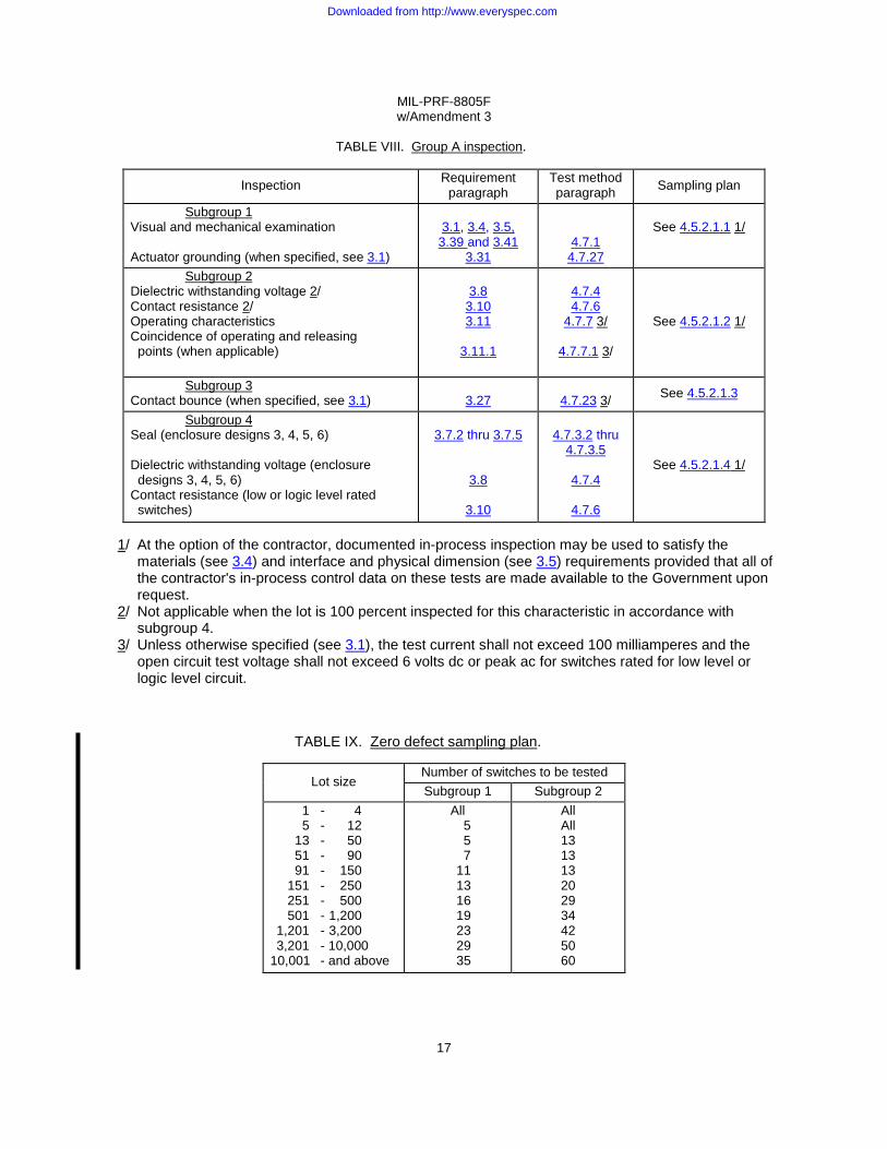
4.5.2 Group A inspection. Group A inspection shall consist of the inspections specified in table VIII. The inspections may be performed in any order, except dielectric withstanding voltage shall be performed after seal testing.
4.5.2.1 Sampling plan. Statistical sampling shall be in accordance with table VIII and table IX. A randomly selected group(s) of samples is required for subgroups 1, 2, and 3. For acceptance of the lot there shall be zero occurrences of defects.
4.5.2.1.1 Subgroup 1. A sample of parts shall be randomly selected in accordance with table IX, subgroup 1 sampling plan.
4.5.2.1.2 Subgroup 2. A sample of parts shall be randomly selected in accordance with table IX, subgroup 2 sampling plan.
4.5.2.1.3 Subgroup 3 (contact bounce) (when specified, see 3.1). Two samples shall be randomly selected from each inspection lot.
4.5.2.1.4 Subgroup 4 . The lot shall be 100 percent inspected to the subgroup 4 tests as applicable.
4.5.2.2 Rejected lots. If an inspection lot is rejected, the lot shall be 100 percent inspected for the defects noted. The contractor may correct all of the defects or remove all of the defective units from the lot. The lot shall then be sampled again in accordance with tables VIII and IX. For acceptance, there shall be zero occurrences of defects. If there are one or more defects in this second sample for the same characteristic that caused the original lot rejection, the lot is rejected. Such lots shall be separate from new lots and shall be clearly identified as reinspected lots.
4.6 Periodic inspection. Periodic inspection shall consist of group B. Except where the results of these
inspections show noncompliance with the applicable requirements (see 4.6.1.5), delivery of products which have passed group A inspection shall not be delayed pending the results of these periodic inspections. 4.6.1 Group B inspection. Group B inspection shall consist of the inspections specified in table X, in the order shown. When a manufacturer has similar products qualified under different specification sheets, the qualifying activity may authorize group B tests which do not require redundant testing on the similar features of these products. Group B inspection shall be performed on sample units selected from inspection lots which have passed group A inspection. A manufacturer's normal quality control tests, production tests, environment tests, and so forth may be used to fulfill all or part of group B inspections; however, all of group B inspections shall be completed as specified.
Downloaded from http://www.everyspec.com
MIL-PRF-8805F w/Amendment 3
16
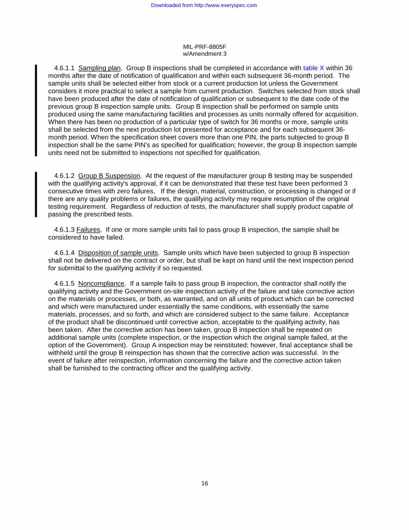
4.6.1.1 Sampling plan. Group B inspections shall be completed in accordance with table X within 36 months after the date of notification of qualification and within each subsequent 36-month period. The sample units shall be selected either from stock or a current production lot unless the Government considers it more practical to select a sample from current production. Switches selected from stock shall have been produced after the date of notification of qualification or subsequent to the date code of the previous group B inspection sample units. Group B inspection shall be performed on sample units produced using the same manufacturing facilities and processes as units normally offered for acquisition. When there has been no production of a particular type of switch for 36 months or more, sample units shall be selected from the next production lot presented for acceptance and for each subsequent 36-month period. When the specification sheet covers more than one PIN, the parts subjected to group B inspection shall be the same PIN's as specified for qualification; however, the group B inspection sample units need not be submitted to inspections not specified for qualification. 4.6.1.2 Group B Suspension. At the request of the manufacturer group B testing may be suspended with the qualifying activity's approval, if it can be demonstrated that these test have been performed 3 consecutive times with zero failures, If the design, material, construction, or processing is changed or if there are any quality problems or failures, the qualifying activity may require resumption of the original testing requirement. Regardless of reduction of tests, the manufacturer shall supply product capable of passing the prescribed tests.
4.6.1.3 Failures. If one or more sample units fail to pass group B inspection, the sample shall be
considered to have failed. 4.6.1.4 Disposition of sample units. Sample units which have been subjected to group B inspection
shall not be delivered on the contract or order, but shall be kept on hand until the next inspection period for submittal to the qualifying activity if so requested.
4.6.1.5 Noncompliance. If a sample fails to pass group B inspection, the contractor shall notify the
qualifying activity and the Government on-site inspection activity of the failure and take corrective action on the materials or processes, or both, as warranted, and on all units of product which can be corrected and which were manufactured under essentially the same conditions, with essentially the same materials, processes, and so forth, and which are considered subject to the same failure. Acceptance of the product shall be discontinued until corrective action, acceptable to the qualifying activity, has been taken. After the corrective action has been taken, group B inspection shall be repeated on additional sample units (complete inspection, or the inspection which the original sample failed, at the option of the Government). Group A inspection may be reinstituted; however, final acceptance shall be withheld until the group B reinspection has shown that the corrective action was successful. In the event of failure after reinspection, information concerning the failure and the corrective action taken shall be furnished to the contracting officer and the qualifying activity.
Downloaded from http://www.everyspec.com
MIL-PRF-8805F w/Amendment 3
17
TABLE VIII. Group A inspection.
Inspection Requirement paragraph
Test method paragraph Sampling plan
Subgroup 1 Visual and mechanical examination Actuator grounding (when specified, see 3.1)
3.1, 3.4, 3.5,
3.39 and 3.41 3.31
4.7.1 4.7.27
See 4.5.2.1.1 1/
Subgroup 2 Dielectric withstanding voltage 2/ Contact resistance 2/ Operating characteristics Coincidence of operating and releasing points (when applicable)
3.8
3.10 3.11
3.11.1
4.7.4 4.7.6
4.7.7 3/
4.7.7.1 3/
See 4.5.2.1.2 1/
Subgroup 3 Contact bounce (when specified, see 3.1)
3.27
4.7.23 3/ See 4.5.2.1.3
Subgroup 4 Seal (enclosure designs 3, 4, 5, 6) Dielectric withstanding voltage (enclosure designs 3, 4, 5, 6) Contact resistance (low or logic level rated switches)
3.7.2 thru 3.7.5
3.8
3.10
4.7.3.2 thru
4.7.3.5
4.7.4
4.7.6
See 4.5.2.1.4 1/
1/ At the option of the contractor, documented in-process inspection may be used to satisfy the
materials (see 3.4) and interface and physical dimension (see 3.5) requirements provided that all of the contractor's in-process control data on these tests are made available to the Government upon request.
2/ Not applicable when the lot is 100 percent inspected for this characteristic in accordance with subgroup 4.
3/ Unless otherwise specified (see 3.1), the test current shall not exceed 100 milliamperes and the open circuit test voltage shall not exceed 6 volts dc or peak ac for switches rated for low level or logic level circuit.
TABLE IX. Zero defect sampling plan.
Lot size Number of switches to be tested Subgroup 1 Subgroup 2
1 - 4 5 - 12 13 - 50 51 - 90 91 - 150 151 - 250 251 - 500 501 - 1,200 1,201 - 3,200 3,201 - 10,000 10,001 - and above
All 5 5 7
11 13 16 19 23 29 35
All All 13 13 13 20 29 34 42 50 60
Downloaded from http://www.everyspec.com

MIL-PRF-8805F w/Amendment 3
18
4.7 Methods of inspection.
4.7.1 Visual and mechanical inspection. Switches shall be inspected to verify that the materials, interface and physical dimensions, marking, and workmanship are in accordance with the applicable requirements (see 3.1, 3.4, 3.5, 3.39 and 3.41). The switching operation of all poles shall be inspected by use of suitable test circuits for compliance with the applicable requirements (see 3.1 and 6.2). 4.7.2 Solderability (see 3.6) Solder type terminations shall be tested in accordance with method 208 of MIL-STD-202. A minimum of two terminals per switch shall be tested.”
4.7.3 Seal (see 3.7).
4.7.3.1 Dusttight (see 3.7.1) (applicable to enclosure requirement 2). Switches shall be tested in
accordance with method 110 of MIL-STD-202. During step 3, the switches shall be mechanically operated for 2,500 cycles. The cycling rate shall not exceed 60 cycles of operation per minute. The second 6-hour test at 63°C (145°F) shall be performed immediately after reaching stabilization in step 2. Subsequent to all applicable tests of table VII group VIII and table X samples 1 through 4, the switches shall be opened and inspected internally for dust. The inspection shall be made using 10-power magnification.
4.7.3.2 Watertight (see 3.7.2) (applicable to enclosure requirement 3). Switches shall be immersed in an enclosure to a depth of 2-3 inches in tap water. The resilient interfacial seal of a connector shall not be immersed in the water. The enclosure shall be subjected to an absolute pressure of 2.0 inches ±0.5 inches of mercury for a period of 2 minutes minimum. During this period the switches shall be observed for leakage as indicated by a continuous stream of bubbles coming from within the switch. A continuous stream of bubbles shall be two or more bubbles present in the water at the same time and originating from the same location on the switch. Bubbles which are the result of entrapped air on the exterior of the switches shall not be considered as leakage. During group A inspection only, switches shall be removed from the water before the pressure of the vacuum chamber is raised to atmospheric pressure. Final measurements: External moisture only shall be removed from the switches. Within 24 hours after removal from the water, atmospheric pressure dielectric withstanding voltage shall be measured as specified in 4.7.4.1. Switches shall be thoroughly dried to remove residual moisture after inspection.
4.7.3.3 Resilient (see 3.7.3) (applicable to enclosure requirement 4). Switches shall be tested in
accordance with method 112 of MIL-STD-202. The following details shall apply:
a) Test condition C.
b) Leakage-rate sensitivity shall be 1 x 10⁻⁶ atm cm3/s under standard conditions.
c) Procedure I, II, III, or IV (as applicable).
During the exposure of helium atmosphere, the differential pressure shall be one atmosphere between the interior and exterior of the switch under test. The vacuum shall be continuously monitored for traces of helium. At the completion of this test, the sample units may be backfilled with an inert gas or air and the bleeder tube pinched off. After pinch off, the pinch off area shall be carefully soldered to assist in obtaining the seal and the seal shall be tested for gross leaks using the watertight seal test (see 4.7.3.2).
Downloaded from http://www.everyspec.com

MIL-PRF-8805F w/Amendment 3
19
TABLE X. Group B inspection.
Inspection Requirement paragraph
Test method
paragraph Sample numbers
1 2 3 4 5 6 7 3 9 10 11 12 13 14 15 16
Solderability 1/ Strength of mounting bushing 1/ Thermal shock Shock Moisture resistance Salt spray (corrosion) Resistance to soldering heat 1/ Contact resistance Low temperature operation Mechanical endurance at low temperature Mechanical endurance at high temperature 2/ Overload cycling Electrical endurance 3/ Inductive load, dc 4/ Resistive load, ac 5/ Intermediate current 3/ 6/ Contact resistance Low level circuit 3/ 6/ Dielectric withstanding voltage Operating characteristics 7/ Coincidence of operating and release points 1/ 7/ Seal 1/ Dielectric withstanding voltage 8/ Marking visibility
3.6
3.14 3.15 3.17 3.19 3.21 3.26 3.10 3.28
3.29
3.29 3.33 3.34 3.34 3.34 3.36 3.10 3.37 3.8
3.11
3.11.1 3.7 3.8
3.20
4.7.2
4.7.10 4.7.11 4.7.13 4.7.15 4.7.17 4.7.22 4.7.6
4.7.24
4.7.25
4.7.25 4.7.29 4.7.30
4.7.30.2 4.7.30.2 4.7.32 4.7.6
4.7.33 4.7.4 4.7.7
4.7.7.1 4.7.3 4.7.4
4.7.16
X X X X
X
X X X X
X X X X
X
X X X X
X
X
X X X X
X
X
X X X X
X
X
X
X
X
X X
X
X
X
X
X
X
X
X X
X
X
X
X
X X
X
X
X
X
X X
X
X
X
X
X X
X
X
X
X
X
X X
X
X X
X
X
X
1/ When applicable. 2/ Mechanical endurance at high temperature is not required when the specified mechanical life is not
greater than the specified electrical life. 3/ All electrical endurance tests shall be completed as specified in this table for sealed switch
assemblies, enclosure designs 2, 3, 4, and 5, regardless of whether the basic switch used is procured to a DoD specification or not.
4/ If rated for use at altitude, test at the rated altitude only. 5/ The test shall be performed only at the sea level and maximum ambient operating temperature
conditions as specified (see 3.1). If no resistive ac load is specified, test resistive dc load. 6/ When specified (see 3.1). 7/ Not applicable for enclosure requirements 1 and 6, samples 3 and 4. 8/ Not applicable for enclosure requirements 1 and 6.
Downloaded from http://www.everyspec.com

MIL-PRF-8805F w/Amendment 3
20
4.7.3.4 Hermetic (see 3.7.4) (applicable to enclosure requirement 5). Switches shall be tested in accordance with method 112 of MIL-STD-202. The following details shall apply:
a) Test condition C.
b) Leakage-rate sensitivity shall be 1 x 10⁻⁸ atm cm3/s under standard conditions.
c) Procedure I, II, III, or IV (as applicable). During the exposure to helium atmosphere (see figure 1), the differential pressure shall be one atmosphere between the interior and exterior of the switch under test. The vacuum shall be continuously monitored for traces of helium. At the completion of this test, the sample units may be backfilled with an inert gas or air and the bleeder tube pinched off. After pinch off, the pinch off area shall be carefully soldered to assist in obtaining the seal and the seal shall be tested for gross leaks using the watertight seal test (see 4.7.3.2).
4.7.3.5 Splashproof (see 3.7.5) (applicable to enclosure requirement 6). With the switch mounted by its normal means, the switch shall be subjected to the splashproof test of MIL-STD-108. During the test, the switch shall be subjected to 20 cycles of actuation without an electrical load. Within 24 hours after removal from the water, atmospheric pressure dielectric withstanding voltage shall be measured as specified in 4.7.4.1.
4.7.4 Dielectric withstanding voltage (see 3.8). Switches shall be tested in accordance with 4.7.4.1 and, when applicable, in accordance with 4.7.4.2 (see 3.1 and 6.2.2).
FIGURE 1. Hermetic seal test setup.
Downloaded from http://www.everyspec.com

MIL-PRF-8805F w/Amendment 3
21
4.7.4.1 At atmospheric pressure. Switches shall be tested in accordance with method 301 of MIL-STD-202. The following details shall apply:
a) Test potential: 1,000 volts rms.
b) Duration of applications shall be one minute for qualification and group B tests; two to five seconds for group A tests.
c) Points of application:
1) Between all terminals and exposed noncurrent carrying metal or grounded parts.
2) Between all terminals of mutually insulated circuits, including between poles.
3) Between all open terminals of the same pole. This measurement is not applicable after electrical endurance.
d) Inspection after test: Switches shall be inspected for evidence of arcing, flashover,
breakdown of insulation, and damage. These tests shall be performed with the switch in normal position, and shall then be repeated for other operating positions.
4.7.4.2 At reduced barometric pressure. Switches rated for operation above 10,000 feet (see 3.1) shall be tested as specified in 4.7.4.1 and in accordance with method 105 of MIL-STD-202. The following details and exceptions shall apply:
a) Test voltage shall be 500 volts rms unless otherwise specified (see 3.1).
b) Unless otherwise specified, test condition C (70,000 feet) (see 3.1).
4.7.5 Insulation resistance (see 3.9). Switches shall be tested in accordance with method 302 of MIL-STD-202. The following details shall apply:
a) Test condition B (500 volts ±10%).
b) Points of measurement:
1) Between each terminal and exposed noncurrent carrying metal or grounded parts. 2) Between all terminals of mutually insulated circuits, including between poles. 3) Between all open terminals of the same pole.
These tests shall be performed with the switch in normal position, and then shall be repeated for other operating positions.
Downloaded from http://www.everyspec.com

MIL-PRF-8805F w/Amendment 3
22
4.7.6 Contact resistance (see 3.10). Switch contacts shall be tested in accordance with method 307 of MIL-STD-202. The following details shall apply:
a) Measurements shall be made between the terminals of the contacts of the same pole forming
a switching circuit. Measurements shall be made for all poles in a switch at each of the actuators extreme positions.
b) Test current: 0.1 ampere. After electrical endurance, use the electrical parameters of the
electrical endurance test load (this also applies to 4.7.6c).
c) Open-circuit test voltage: 6 V dc ±1 V dc.
d) Number of actuations prior to measurement: Three.
e) Number of test actuations: Three.
f) Number of measurements per actuation: One.
4.7.7 Operating characteristics (see 3.11). Switches shall be measured for operating characteristics as specified (see 3.1 and 6.2).
4.7.7.1 Coincidence of operating and releasing points (see 3.11.1). Coincidence of operating (releasing) points of all poles of a multipole switch shall be determined with suitable indicating circuits. The switch shall be rigidly held in a suitable fixture allowing the actuator to be moved in its intended manner. The actuator shall be advanced and retracted slowly and uniformly with no external vibratory influence while passing through the operating and releasing points, at a rate not exceeding 0.001 inch or 1 degree per second.
4.7.8 Terminal strength (see 3.12). Switches shall be mounted by their normal mounting means and
subjected to the tests of 4.7.8.1 through 4.7.8.3, as applicable. After the test, the switches shall be inspected for evidence of short-circuiting, breakage, loosening of terminals, or damage to the body of the switch. A circuit, such as a pilot light, shall be used to monitor the test. No terminal shall be tested in more than one direction.
4.7.8.1 Screw terminals. Screw terminals shall be subjected to the tests specified in 4.7.8.1.1 and 4.7.8.1.2.
4.7.8.1.1 Pull. The terminals shall be subjected to a pull of the applicable static force specified in Table XI. The following details shall apply:
a) Duration shall be one minute.
b) Direction of the pull shall be along the axis of the terminal screw, perpendicular to the axis of the terminal screw, and in the direction most likely to cause failure.
4.7.8.1.2 Torque. Terminals of the switches shall be tested in accordance with method 211 of
MIL-STD-202. The following details and exceptions shall apply:
a) Test condition E, except thread size 10-24 the torque shall be 24.0 pound-inches.
b) Direction of torque shall be in the direction which will tighten the screws.
Downloaded from http://www.everyspec.com

MIL-PRF-8805F w/Amendment 3
23
TABLE XI. Static values of force.
Thread size
Force in pounds
4-40 6-32 8-32 10-32 10-24 1/4-28
5 30 35 40 40 50
4.7.8.2 Solder terminals. Switches shall be tested in accordance with method 211 of MIL-STD-202.
The following details and exceptions shall apply:
a) Test condition A.
b) Applied force shall be 9 pounds; 3 pounds minimum pull for terminals designed for direct insertion into printed circuit boards.
c) Directions of force shall be parallel to the long axis of the terminal, perpendicular to the long axis of the terminals, and in the direction most likely to cause failure.
4.7.8.3 Wire-lead terminals. Switches shall be tested in accordance with method 211 of MIL-STD-202.
The following details and exceptions shall apply:
a) Test condition A.
b) Applied force shall be 15 pounds.
4.7.9 Strength of actuating means (see y). With the switches mounted by their normal mounting means, a static load of 10 pounds shall be gradually applied to the actuator and maintained for a period of 1 minute. The force resulting from application of the static load shall be in a direction to cause actuation of the switch. A circuit, such as a pilot light, shall be used to monitor the normally open switch contacts to assure that they do not open during the application of the static load.
4.7.10 Strength of mounting bushing (see 3.14). Bushing-mounted switches shall be mounted on a
metal panel by their normal mounting means with the hardware specified (see 3.1 and 6.2). A torque of 15 pound-inches shall be applied to the mounting nut. If the unit incorporates a nonturn device, the mounted switch body shall be subjected to a torque of 5 pound-inches.
4.7.11 Thermal shock (see 3.15). Switches shall be tested in accordance with method 107 of MIL-STD-202. The following details shall apply:
a) Test condition: A, for temperature characteristic 1; B, for temperature characteristic 2; C, for temperature characteristic 3; D, for temperature characteristic 4.
b) Measurements before and after cycling: Not applicable. c) Inspections after test: Switches shall be inspected for mechanical and electrical damage and
loosening of rivets or other fastening devices.
Downloaded from http://www.everyspec.com

MIL-PRF-8805F w/Amendment 3
24
4.7.12 Vibration (see 3.16). Switches shall be tested as specified in 4.7.12.1, and in addition, when specified (see 3.1 and 6.2), as specified in 4.7.12.2. The following details and exceptions shall apply to swept sinusoidal and random vibration:
a) Tests and measurements prior to vibration: Not applicable. b) Mounting: Switches shall be rigidly mounted by their normal mounting means on a rigid
metal panel. The mounting fixture shall be free from resonance’s over the test frequency range. Where connectors are part of the switch, the complete connector shall be tested with the switch.
c) Monitoring of open and closed circuits: All open and closed circuits shall be monitored.
Unless otherwise specified (see 3.1), half of the alternate action units shall be tested with the actuating means in one position and the other half of the units shall be tested with the actuating means in an alternate position. Open circuits may be connected in parallel and monitored for closing, and closed circuits may be connected in series and monitored for opening. With the circuits so wired, in the event of indication of failure, the test shall be modified by successive testing with the contacts monitored, switch by switch, to determine which, if any, contacts are defective. If one or more contacts fail singularly, the switches shall be considered to have failed.
d) Test and measurements during vibration: Switch-contact stability shall be continuously
monitored during vibration, using method 310 of MIL-STD-202, test condition A, test circuit B.
e) Tests and measurements after vibration: Not applicable. f) Inspections after test: Switches shall be inspected for evidence of broken, deformed,
displaced, or loose parts. 4.7.12.1 Swept sinusoidal. Switches shall be tested in accordance with method 204 of MIL-STD-202.
The following details and exceptions shall apply:
Test condition: A, for vibration grade 1; B, for vibration grade 2; D, for vibration grade 3, except that acceleration level shall be 30 G and the upper level of the frequency range shall be 3,000 hertz.
4.7.12.2 Random vibration (when specified, see 3.1 and 6.2). Switches shall be tested in accordance
with method 214 of MIL-STD-202, test condition I. Duration of test shall be 90 minutes in each of three mutually perpendicular directions, one of which shall be in the direction of actuator movement. The test condition letter is identified as follows:
A through F, for random vibration categories A through F respectively.
Downloaded from http://www.everyspec.com
MIL-PRF-8805F w/Amendment 3
25
4.7.13 Shock (see 3.17). Unless otherwise specified (see 3.1), switches shall be tested as specified in 4.7.13.1, method I, and in addition, when specified (see 3.1), as specified in 4.7.13.2, method II. The following details and exceptions shall apply to method I and method II:
a) Special mounting means: Switches shall be mounted on a rigid metal panel by their normal mounting means.
b) Electrical load conditions: The electrical load shall consist of the monitor circuit only.
c) Half of the alternate action units shall be tested with the actuating means in one position and
the other half of the units shall be tested with the actuating means in an alternate position. Open circuits may be connected in parallel and monitored for closing. Closed circuits may be connected in series and monitored for opening. In the event of indication of opening or closing of contacts greater than that allowed, the test shall be modified by applying successive identical blows in the same plane to monitor contacts, switch by switch, to determine if a switch is defective.
d) Measurements during shock: Switch-contact stability shall be continuously monitored during
shock using method 310 of MIL-STD-202, test circuit B.
e) Measurement after shock: Not applicable.
f) Measurement after test: There shall be no evidence of broken, deformed, displaced, or loose parts.
4.7.13.1 Method I (applicable to shock type M). Switches shall be tested in accordance with method
213 of MIL-STD-202. The following details shall apply:
a) Test condition I (100 g, sawtooth).
b) Monitoring: Method 310 of MIL-STD-202, test condition A. 4.7.13.2 Method II (applicable to shock type H, high impact). Switches shall be tested in accordance
with method 207 of MIL-STD-202. Switch contacts shall be monitored in accordance with method 310 of MIL-STD-202, test condition D.
4.7.14 Acceleration (see 3.18). When specified (see 3.1), switches shall be subjected to an
acceleration force of 20 G attained within 2 minutes. The force shall be maintained for 1 minute in each direction along each of its three mutually perpendicular axis. The switches shall be monitored for opening of closed contacts and closing of open contacts with a circuit such as a pilot lamp. Half of the units shall be tested with the actuating means in one position and the other half of the units shall be tested with the actuating means in an alternate position.
4.7.15 Moisture resistance (see 3.19). Switches shall be tested in accordance with method 106 of
MIL-STD-202. The following details and exceptions shall apply:
a) Mounting: By normal mounting means on a corrosion-resistant metal panel extending beyond the switch, positioned 15 degrees from vertical and uninsulated. Half of the alternate action units shall be tested with the actuating means in one position and the other half of the units shall be tested with the actuating means in an alternate position.
b) Polarization: During steps 1 to 6 inclusive, a polarizing voltage of 100 volts dc shall be
applied between all terminals tied together and the metal panel. The negative polarity shall
Downloaded from http://www.everyspec.com

MIL-PRF-8805F w/Amendment 3
26
be applied to the metal panel. Steps 7a and 7b are not applicable.
c) Load voltage: Not applicable.
d) Final measurements: Within 5 minutes after conclusion of the test and while the switches are still wet, insulation resistance shall be measured as specified in 4.7.5. At the end of the 24-hour drying period, insulation resistance shall again be measured as specified in 4.7.5. If the insulation resistance at the 5 minute reading is greater than the required 24 hour readings, no measurement is required at 24 hours.
e) Inspections during final measurement and after test: Switches shall be inspected for evidence
of corrosion, breaking, cracking, or spalling. Mounting hardware shall be removed at the end of the test.
f) Water, steam, distilled or deionized water shall be used for this test.
4.7.16 Marking visibility (see 3.20). Subsequent to the inspections of groups II, III and IV of table VII and the applicable inspections of table X, switches shall be inspected for legibility of required marking (see 3.39). Maximum magnification of 5X may be used.
4.7.17 Salt spray (corrosion) (see 3.21). Switches shall be tested in accordance with method 101 of MIL-STD-202 with associated mounting and terminal hardware assembled. The following details and exceptions shall apply:
a) Test condition A. b) Switches, of enclosure design 2, shall be subjected to 10 cycles of operation of making and
breaking the rated resistive current at the lowest dc voltage specified (see 3.1 and 6.2), immediately after the gentle wash or dip and light brushing. Sealed switches (designs 3, 4, and 5) shall be subjected to these 10 cycles of operation after a 6-hour drying period in a forced-draft oven at a temperature of approximately 57°C.
c) Unless otherwise specified five percent salt solution.
4.7.18 Icing (when specified, see 3.1) (see 3.22). Switches shall be carefully cleaned to remove
grease or other foreign material from surfaces that will be in contact with the ice. Switches with test leads attached shall be mounted by their normal mounting means within individual fixtures so designed that the actuator of the switch can be individually and suddenly released from its full overtravel position. The fixture shall not impede or assist the fracture of the ice or the subsequent release of the actuator. The fixture shall be so designed that releasing the switch actuator does not exert any stress upon the ice coating except the stress applied by the test switch itself. The fixture shall be designed to support and continuously maintain the test switch in an attitude such that the actuating member moves upward when released by the fixture. The fixture shall be designed to provide a minimum of heat transfer between the fixture and the test switch. (See figure 2 for suggested icing test fixtures.) During the test, no part of the ice coating shall come into physical contact with any surface other than that of the fixture or test switch or the water during immersion. It shall not be exposed to warm drafts, and shall not be brought into close proximity to any heated object or surface. The fixture, with switch installed, shall be conditioned at -8°C for at least 10 hours immediately prior to the first water immersion. Clear glaze-ice coatings shall be formed over the switch by alternately dipping it in distilled water at 0°C to +1°C for 5 seconds and placing it in a cold chamber at -8°C for at least 30 minutes. The switch shall not be removed from the temperature chamber for a longer period than 15 seconds to perform the immersion cycle. Ice cubes made from distilled water may be placed in the water bath to aid in maintaining its temperature, but the
Downloaded from http://www.everyspec.com

MIL-PRF-8805F w/Amendment 3
27
ice coating shall not be allowed to touch floating ice. During the 5-second immersion, the switch shall be completely submerged and shall remain stationary; the water shall not be stirred while the switch is immersed. The ice coating shall be not less than .062-inch thick. The ice coating shall not be mechanically disturbed before the fixture releases the switch actuating member for evaluation. At the conclusion of the final low temperature exposure, the fixture containing the switch shall be removed from the low temperature chamber and, within 20 seconds, a pilot lamp circuit shall be connected to the test leads attached to the switch terminals and the fixture shall suddenly and completely release the switch actuator and operate for 50 cycles of operation at room ambient temperature.
4.7.19 Sand and dust (when specified, see 3.1) (see 3.23). Switches shall be tested in accordance
with method 110 of MIL-STD-202. During step 3, the switches shall be mechanically operated for 2,500 cycles. The cycling rate shall not exceed 60 cycles of operation per minute. The second 6-hour test at 63°C (145°F) shall be performed immediately after reaching stabilization in step 2.
4.7.20 Explosion (see 3.24). Switches shall be tested in accordance with method 109 of MIL-STD-202. Switches shall be operated at their maximum rated dc inductive current and open-circuit voltage (see 3.1 and 6.2).
4.7.21 Permanency of marking (see 3.25) (applicable to switches with printed circuit board mount terminals. Switches shall be tested in accordance with MIL-STD-202, method 215. The following details shall apply:
a) Portion of switch to be brushed: Brush strokes of each solvent solution shall be evenly divided between required identification, terminal, and circuit schematic markings.
b) Mechanical or electrical damage: There shall be no damage to the switch at the conclusion of the test sequence.
4.7.22 Resistance to soldering heat (see 3.26) (applicable to switches with solderable terminals) (not
applicable to switches with integral leadwire terminals). Switches with wire connection terminals shall be tested in accordance with 4.7.22.1. Switches with printed circuit (PC) terminal pins shall be tested in accordance with 4.7.22.2. Following completion of the procedure, a visual inspection for deformation or other damage shall be performed at 7X magnification. Subsequent to all applicable follow-on testing of tables VII and X, the switches shall be opened and inspected at 7X magnification for deformation or other damage.
4.7.22.1 Resistance to soldering heat (for wire connection terminals). Switches shall be tested in
accordance with EIA-448-22 as follows:
a) A temperature controlled soldering iron capable of maintaining the idling tip temperature within ±10°C, rated for 25 watts with a wedge tip shall be used.
b) The solder shall be lead-tin alloy with a nominal tin content of 60 to 63 percent. It will be in
the form of flux cored solder wire of no more than 0.062 inch nominal outside diameter, with an R or RMA flux core which occupies approximately 3.3 percent by weight.
c) The test shall be performed on all of the solder terminations of the switch. d) The applicable copper wire, of the size required for the electrical endurance test, properly
prepared for the solder eye size, shall be inserted in the appropriate manner. If the switch terminals are of the wraparound type, the wire shall be wound around the applicable portion of the terminal 1/2 to 3/4 turn.
Downloaded from http://www.everyspec.com
MIL-PRF-8805F w/Amendment 3
28
e) The soldering iron shall be heated to 360°C ±10°C. The time of application shall be 4 to 5 seconds during which the solder shall also be applied in an amount commensurate with good soldering technique.
f) The soldering iron and the solder shall be applied to that portion of the terminal that is
intended to receive the connecting wire and is closest to the switch housing.
g) During application of the solder and soldering iron, a force of 3 to 4 ounces shall be applied to the terminal by the soldering iron in a direction perpendicular to the major flat or diameter portion of the terminal intended to receive the connecting wire.
4.7.22.2 Resistance to soldering heat (applicable to switches with terminals intended for direct insertion
into printed circuit boards). Switches shall be tested in accordance with method 210 of MIL-STD-202. The following details shall apply:
a. Depth of immersion: Terminals shall be immersed to within 2 to 2.5 mm (.079 inch to .099inch) of the switch body.
b. Test condition B.
c. Cooling time: Not applicable.
d. Inspections and measurements:
1) Before: None. 2) After: See 4.7.22.
4.7.23 Contact bounce (when specified, see 3.1 and 6.2) (see 3.27). The contact bounce occurring
under the initial conditions of closing contacts shall be measured by mechanically actuating the plunger in a direction parallel to the allowable plunger travel by means of a mechanical cycler. The method of observing shall be by means of an oscilloscope trace or equivalent test method. The oscilloscope band width shall be not less than 50,000 Hz. The mechanical cycling means shall include a triggering circuit such that the quiescent contact state shall be viewed prior to the initial closing of the contacts. An example of a typical recording of contact bounce is shown on figure 3. The electrical circuit shown on figure 4, or an equivalent, shall be utilized. The actuation rate shall be as specified in 4.7.23.1 or 4.7.23.2, as applicable. The contact bounce readings shall be the maximum occurring in ten consecutive readings.
4.7.23.1 Sensitive and limit switches. Sensitive and limit type switches shall be tested with a plunger
actuation rate of .001 inch ±.0005 inch per second. 4.7.23.2 Manual switches. Manual switches shall be tested with an actuator rate of 6 inches ± 2 inches
per second.
Downloaded from http://www.everyspec.com

MIL-PRF-8805F w/Amendment 3
29
Inches mm Inches mm
.001 0.03 .093 2.36 .005 0.13 .094 2.39 .010 0.25 .096 2.44 .015 0.38 .099 2.51
| | | | | | | .031 0.79 .125 3.18 | Actuator DIA | .062 | .093 | .125 | .250 | .375 | .062 1.57 .250 6.35 | | | | | | | .375 9.53 | "A" DIA | .015 | .031 | .031 | .062 | .062 |
NOTES: 1. Dimensions are in inches. 2. Metric equivalents are given for information only. 3. Fixture is not to be dipped deeper than ice thickness indicator.
FIGURE 2. Suggested icing test fixtures.
Downloaded from http://www.everyspec.com
MIL-PRF-8805F w/Amendment 3
30
4.7.24 Low temperature operation (see 3.28). Half of the sample units shall be mounted in a fixture
which depresses the actuating member to its full overtravel position; and half of the sample units shall be similarly mounted with actuating members depressed with the normally open contacts closed, and the actuator held in the differential travel range. The fixtures shall be designed to afford a minimum of heat transfer between the fixture and switch. The fixtures shall permit free circulation of air around the test switch, and shall be designed to provide sudden and complete release of the switch actuating member. The fixtures containing the sample units shall be placed in a low temperature chamber provided with forced circulation, and the chamber shall be brought to the minimum temperature specified (see 3.1 and 6.2). The temperature shall then be maintained at this level for 24 hours. With the test chamber maintained at the specified low temperature, the fixtures shall be removed from the chamber individually, and within 5 seconds, the test switch actuating member shall be suddenly and fully released by the fixture. A pilot lamp circuit shall be used to observe switch behavior.
4.7.25 Mechanical endurance (see 3.29). Switches shall be subjected to mechanical operation cycling at a rate of 60 cycles ±5 cycles per minute for momentary action units and 30 cycles ±5 cycles per minute for alternate action units. Unless otherwise specified (see 3.1), each stroke of the actuating means shall include the full range of travel from free position to full overtravel position and return to the fully released position. The actuation force applied to the switch actuator shall be the force required to reach the extreme position of travel +30 percent -0 percent. Switch contacts shall be monitored for circuit continuity a minimum of one minute per hour for the duration of the test. Two switches shall be tested at each ambient temperature condition: rated high temperature, and rated low temperature. The switches shall be subjected to the number of cycles specified (see 3.1 and 6.2).
4.7.26 Short circuit (see 3.30 and 3.1). Switches shall be tested as specified in 4.7.26.1, method I, or
when specified (see 3.1), switches shall be tested as specified in 4.7.26.2, method II.
4.7.26.1 Method I. The switch shall be inserted in a circuit calibrated to supply current equal to 60 times the rated resistive load at the lowest rated dc voltage specified (see 3.1). The switch shall be connected in series to a thermal-type circuit breaker or a fuse in accordance with figure 5. A circuit breaker shall be used for switches having a rated resistive load of 10 amperes or greater, and a fuse for switches having a rated resistive load less than 10 amperes. The connecting wire shall be of a size for single use in free air as specified in table XII as determined by the rated resistive load of the switch (see 3.1). If the rated load of the switch does not coincide with a wire size, the next larger wire size shall be used. The terminals shall be in accordance with SAE-AS7928. The circuit breaker and fuse shall be in accordance with SAE-AS58091 and MIL-PRF-15160/2, respectively, and in accordance with table XII. If the rated load of the switch does not coincide with a circuit breaker or fuse current rating, the next larger breaker or fuse shall be employed. Calibration shall be made with a substitute circuit breaker (or equivalent fuse), less the test switch and with the switch leads in the circuit. With both the switch under test and the circuit breaker (or fuse) in a closed position as shown on figure 5, the circuit shall be closed manually by switch S1. The test shall be conducted five times. A minimum of 2 minutes shall elapse between the successive closings of switch S1. The circuit breaker shall be reset or the fuse replaced after each closure. For double-throw switches, half the switches shall be tested in one position, and the remaining half shall be tested in the alternate position.
4.7.26.2 Method II. Method II is similar to method I except as follows: The calibrated circuit shall be closed by the switch under test, and after the circuit breaker or fuse interrupts the circuit, the test switch shall be returned to the "off" position. After the test switch actuator is returned to the "off" position, the switch contacts shall be checked for proper opening by any suitable continuity test method. This procedure shall be repeated 10 times. The switch contacts under test must open after each closure operation, and there shall be no mechanical failure or damage to the switch case.
Downloaded from http://www.everyspec.com
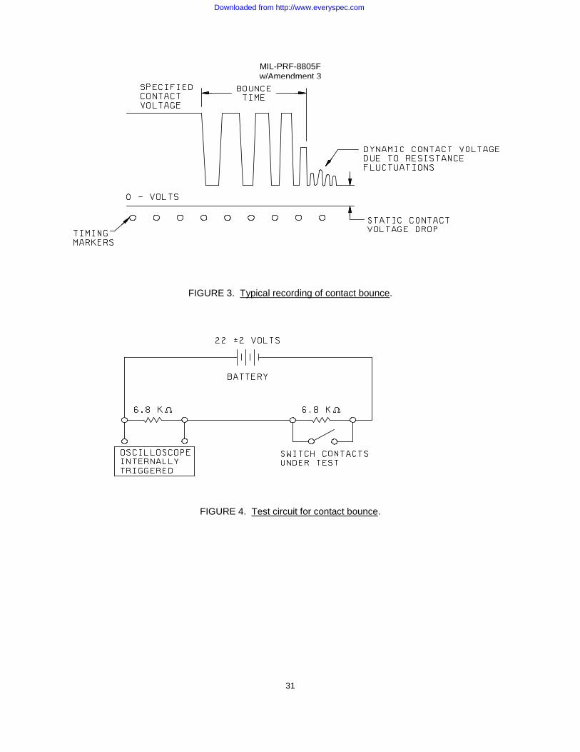
MIL-PRF-8805F w/Amendment 3
31
FIGURE 3. Typical recording of contact bounce. FIGURE 4. Test circuit for contact bounce.
Downloaded from http://www.everyspec.com

MIL-PRF-8805F w/Amendment 3
32
FIGURE 5. Circuit diagram for short circuit test.
TABLE XII. Wire size, circuit breaker and fuse requirements for
short circuit and electrical endurance tests.
Resistive rating at lowest voltage Wire size Circuit breaker or fuse Less than 10 amperes
10 amperes 15 amperes 18 amperes 20 amperes 25 amperes 30 amperes 40 amperes
AN-20
AN-18 AN-18 AN-16 AN-16 AN-14 AN-14 AN-12
MIL-PRF-15160/2, characteristics "A" rating, as applicable
MS25244-10 1/
MS25244-15 1/ MS25244-20 1/ MS25244-20 1/ MS25244-25 1/ MS25244-30 1/ MS25244-50 1/
1/ Military Standard Drawing MS25244 is canceled and supersede by SAE-AS25244 although the part
numbers shall conform to the example below: MS25244 P 10 Basic part number Mounting and /or Amperage rating terminal configuration
Downloaded from http://www.everyspec.com

MIL-PRF-8805F w/Amendment 3
33
4.7.27 Actuator grounding (when specified, see 3.1 and 6.2) (see 3.31). Resistance between the mounting bushing and the actuator shall be measured in accordance with method 307 of MIL-STD-202. The following details and exceptions shall apply:
a) Method of connection: Between a suitable exterior point on the mounting bushing and the switch actuator (or shield when applicable).
b) Test current: 100 ±10 milliamperes.
c) Maximum open-circuit test voltage: 6 V dc.
d) Number of actuations prior to measurement: Three.
e) Number of test actuations: Three.
f) Number of measurements per actuation: One.
g) Measurement shall be made in each actuator position including all momentary positions.
There shall be no exterior force applied to actuator during measurement in maintained positions.
4.7.28 Shielding efficiency (when specified, see 3.1 and 6.2) (see 3.32). Switches shall be tested
utilizing a test setup (or equivalent) as shown on figure 6. Measurements shall be made as follows:
a) With the door open and the antennas in the "initial setup" position, establish a test level over the 200 MHz to 1 GHz range such that the received signal level is at least as many dB above the RF ambient level as that of the shielded enclosure attenuation.
b) Record the received signal level and the signal generator output level. Repeat
measurements at 100, 200, 400, 600, 800, and 1,000 MHz.
c) Move the antennas to the final test positions, close the door, and with a RF-tight blank panel between the antennas, measure the integrity of the enclosure by setting the signal generator to the same output and record the received signal level for each frequency used in step b. The shielded enclosure attenuation is then calculated using the following equation:
Attenuation (dB) = 20 log
Where E1 is the receiver reading in step b and E2 is the receiver reading in step c.
d) Mount the test switch in the blank panel with the rear of the switch outside of the shielded enclosure (toward the signal generator antenna). The switch shall be mounted as it would be for normal installation using the mounting hardware supplied or recommended. Repeat the measurements of step c above and calculate the shielding attenuation of the switch using the new receiver readings.
E1 E2
Downloaded from http://www.everyspec.com
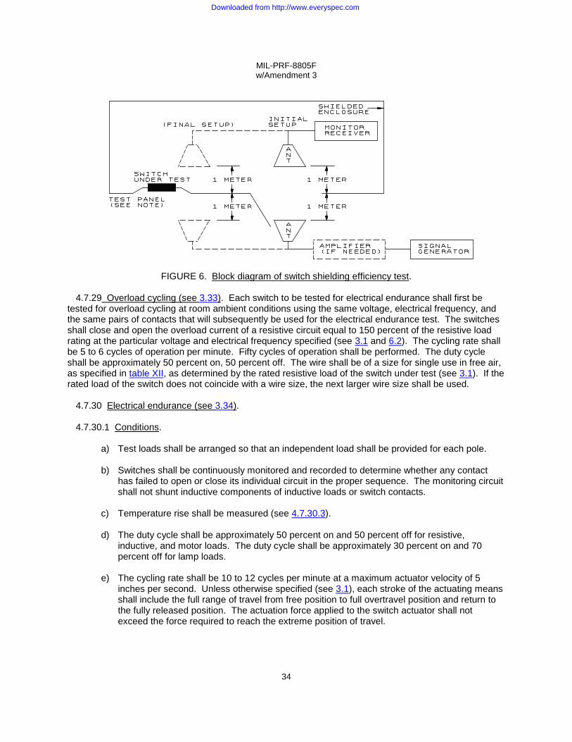
MIL-PRF-8805F w/Amendment 3
34
FIGURE 6. Block diagram of switch shielding efficiency test.
4.7.29 Overload cycling (see 3.33). Each switch to be tested for electrical endurance shall first be tested for overload cycling at room ambient conditions using the same voltage, electrical frequency, and the same pairs of contacts that will subsequently be used for the electrical endurance test. The switches shall close and open the overload current of a resistive circuit equal to 150 percent of the resistive load rating at the particular voltage and electrical frequency specified (see 3.1 and 6.2). The cycling rate shall be 5 to 6 cycles of operation per minute. Fifty cycles of operation shall be performed. The duty cycle shall be approximately 50 percent on, 50 percent off. The wire shall be of a size for single use in free air, as specified in table XII, as determined by the rated resistive load of the switch under test (see 3.1). If the rated load of the switch does not coincide with a wire size, the next larger wire size shall be used.
4.7.30 Electrical endurance (see 3.34).
4.7.30.1 Conditions.
a) Test loads shall be arranged so that an independent load shall be provided for each pole. b) Switches shall be continuously monitored and recorded to determine whether any contact
has failed to open or close its individual circuit in the proper sequence. The monitoring circuit shall not shunt inductive components of inductive loads or switch contacts.
c) Temperature rise shall be measured (see 4.7.30.3). d) The duty cycle shall be approximately 50 percent on and 50 percent off for resistive,
inductive, and motor loads. The duty cycle shall be approximately 30 percent on and 70 percent off for lamp loads.
e) The cycling rate shall be 10 to 12 cycles per minute at a maximum actuator velocity of 5
inches per second. Unless otherwise specified (see 3.1), each stroke of the actuating means shall include the full range of travel from free position to full overtravel position and return to the fully released position. The actuation force applied to the switch actuator shall not exceed the force required to reach the extreme position of travel.
Downloaded from http://www.everyspec.com

MIL-PRF-8805F w/Amendment 3
35
f) For double throw switches, one half of the switches shall be tested with the load circuit connected to one throw, and the remaining half of the switches shall be tested with the load circuit connected to the other throw.
g) In any of the specified load tests, each conductor shall be of an applicable size for single use
in free air as listed in table XII. If the switch rating under test does not coincide with a wire size, the next larger diameter wire shall be used.
h) One side of the power supply, one side of the test load, the switch mounting plate, metal case
(if applicable), and the actuating member, if metal, shall be connected to a common ground.
i) Altitude tests and motor load tests shall be conducted at room ambient air temperature condition only. All switches tested to all other loads shall be subjected to the number of cycles specified (see 3.1 and 6.2) at the maximum ambient air temperature as identified by the temperature characteristic (see 3.1 and 6.2). Each segment of electrical endurance cycling at high temperature shall be continuous for a minimum of 4 hours.
j) The dc power source shall provide the rated or inrush current on resistive loads within 300
microseconds after closing the circuit with a bounceless contact device. Oscillograms shall be provided with the test report documenting this power source characteristic.
k) Electrical tolerances are as follows:
1) Voltage: ±5 percent for dc; ±7 percent for ac. 2) Frequency: ±5 percent. 3) Current: ±5 percent.
4.7.30.2 Loads. Voltage, current, frequency, altitude, and operating cycles shall be as specified (see
3.1 and 6.2). Unless otherwise specified, ac tests are to be 60 Hz. Where different current ratings for 60 and 400 Hz are shown, both 60 and 400 Hz tests are to be performed. The loads are as follows:
a) Resistive load, dc. b) Inductive load, dc shall use inductors which have response and stored energy values as
indicated in figure 7 and figure 8.
c) Lamp load, dc: Tungsten lamps, which provide the rated, steady state lamp current shall be used. The circuit shall be arranged so as to provide a minimum of 15 seconds cooling time preceding each time a lamp is energized. Only tungsten lamps having a nominal wattage not to exceed 50 watts, at the switch voltage specified (see 3.1 and 6.2), shall be used to make up the load. At the option of the manufacturer, a synthetic lamp load may be used for this test. The synthetic lamp load shall consist of making 10 times the rated lamp load and breaking the rated lamp load. The duration of the 10 times inrush current shall be 0.015 seconds minimum.
d) Motor load, dc: The duration of the inrush current shall be not less than .05 second. Only
resistive components shall be used. Switches shall make 6 times the rated load, and break the rated load.
e) Resistive load, ac.
f) Inductive load, ac: Inductive ac load test circuits shall consist of inductive and resistive load
element connected in series. The circuit parameters shall be rated inductive load current at 0.7 ±0.05 lagging power factor at 115 volts.
Downloaded from http://www.everyspec.com
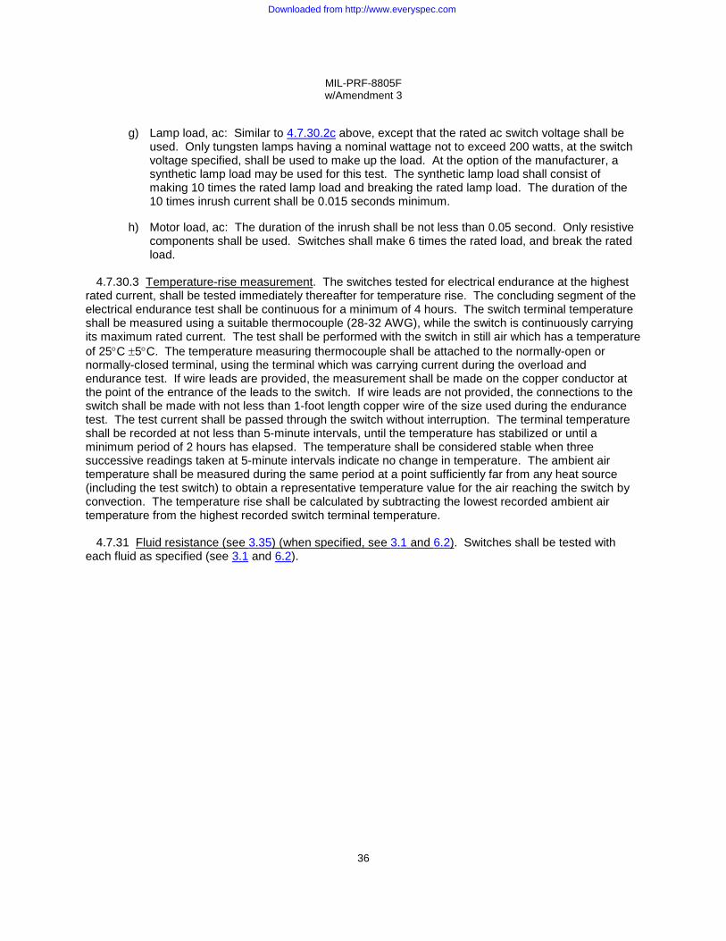
MIL-PRF-8805F w/Amendment 3
36
g) Lamp load, ac: Similar to 4.7.30.2c above, except that the rated ac switch voltage shall be
used. Only tungsten lamps having a nominal wattage not to exceed 200 watts, at the switch voltage specified, shall be used to make up the load. At the option of the manufacturer, a synthetic lamp load may be used for this test. The synthetic lamp load shall consist of making 10 times the rated lamp load and breaking the rated lamp load. The duration of the 10 times inrush current shall be 0.015 seconds minimum.
h) Motor load, ac: The duration of the inrush shall be not less than 0.05 second. Only resistive
components shall be used. Switches shall make 6 times the rated load, and break the rated load.
4.7.30.3 Temperature-rise measurement. The switches tested for electrical endurance at the highest rated current, shall be tested immediately thereafter for temperature rise. The concluding segment of the electrical endurance test shall be continuous for a minimum of 4 hours. The switch terminal temperature shall be measured using a suitable thermocouple (28-32 AWG), while the switch is continuously carrying its maximum rated current. The test shall be performed with the switch in still air which has a temperature of 25°C ±5°C. The temperature measuring thermocouple shall be attached to the normally-open or normally-closed terminal, using the terminal which was carrying current during the overload and endurance test. If wire leads are provided, the measurement shall be made on the copper conductor at the point of the entrance of the leads to the switch. If wire leads are not provided, the connections to the switch shall be made with not less than 1-foot length copper wire of the size used during the endurance test. The test current shall be passed through the switch without interruption. The terminal temperature shall be recorded at not less than 5-minute intervals, until the temperature has stabilized or until a minimum period of 2 hours has elapsed. The temperature shall be considered stable when three successive readings taken at 5-minute intervals indicate no change in temperature. The ambient air temperature shall be measured during the same period at a point sufficiently far from any heat source (including the test switch) to obtain a representative temperature value for the air reaching the switch by convection. The temperature rise shall be calculated by subtracting the lowest recorded ambient air temperature from the highest recorded switch terminal temperature.
4.7.31 Fluid resistance (see 3.35) (when specified, see 3.1 and 6.2). Switches shall be tested with each fluid as specified (see 3.1 and 6.2).
Downloaded from http://www.everyspec.com

MIL-PRF-8805F w/Amendment 3
37
4.7.32 Intermediate current (when specified, see 3.1) (see 3.36). One throw of each pole of the switches under test shall be connected into a circuit having a 27 +3, -0 volt dc source and a load consisting of the coil of relay M5757/10-039 of MIL-R-5757/10, or equivalent. Switch performance during the test shall be continuously monitored. The monitoring equipment shall provide a record of the number of cycles and shall record failures or discontinue the test if a failure occurs. During each closure, the contact potential shall be monitored for at least 40 percent of the time the contacts are closed. Unless otherwise specified (see 3.1) the number of operations shall be 50,000 cycles. The switch shall be cycled by a mechanical actuating device. During each cycle of operation, the actuating member of the switch shall be moved once to each extreme of its travel. Double-throw switches shall be tested with half of the sample lot controlling the load with the normally open contacts and half controlling the load with the normally closed contacts. Each multipole switch shall be connected with all normally open circuits loaded simultaneously or all normally closed circuits loaded simultaneously. The frequency of actuation shall be compatible with the time response characteristics of the switch and monitoring device. Prior to testing, each switch shall be subjected to a 24-hour minimum conditioning in air at the maximum rated temperature as identified by the temperature characteristic (see 3.1 and 6.2). The test shall then be performed at the following operating temperatures:
a) Twenty-five percent of the test cycles at the minimum ambient air temperature as identified by the temperature characteristic (see 3.1 and 6.2).
b) Fifty percent of the test cycles at room ambient air temperature.
c) Twenty-five percent of the cycles at the maximum ambient air temperature as identified by
the temperature characteristic (see 3.1 and 6.2). 4.7.33 Low level circuit (when specified, see 3.1 and 6.2) (see 3.37). Switches shall be tested for the
number of cycles specified (see 3.1 and 6.2), as follows:
a) Contact load: Each switch contact shall make, carry, and break a resistive load of 10 milliamperes maximum at an open circuit voltage of 30 millivolts maximum dc or peak ac. Both normally open and normally closed contacts shall be loaded. Contacts shall be connected to individual loads.
b) Operate cycles: Rate not to exceed 60 cycles per minute with nominally equal "on" and "off"
times.
c) Monitoring circuit: The monitoring equipment shall provide a record of the number of cycles and shall record failures or discontinue the test if a failure occurs. During each closure, the contact potential shall be monitored for at least 50 percent of the time the contacts are closed.
d) Operating temperatures:
(1) Twenty-five percent of the test cycles at the minimum ambient air temperature as identified
by the temperature characteristic (see 3.1 and 6.2).
(2) Twenty-five percent of the test cycles at room ambient air temperature.
(3) Fifty percent of the cycles at the maximum ambient air temperature as identified by the temperature characteristic (see 3.1 and 6.2).
Downloaded from http://www.everyspec.com

MIL-PRF-8805F w/Amendment 3
38
4.7.34 Logic level circuit (when specified, see 3.1) (see 3.38). Switches shall be tested in accordance with EIA RS-448-4, method 17 as follows:
a) Contact load: Each switch contact shall make, carry, and break a resistive load of 10 mA ±1 mA at an open circuit voltage of 5.0 V dc ±0.5 V dc. Both normally open and normally closed contacts shall be loaded. Contacts shall be connected to individual loads.
b) Cycles of operation. Unless otherwise specified (see 3.1 and 6.2), the number of cycles of
operation shall be 50,000. The actuation rate shall be 120 cycles per minute maximum. Unless otherwise specified (see 3.1 and 6.2), each stroke of the actuating means shall include the full range of travel from free position to full overtravel position and return to the fully released position. The actuation force applied to the switch actuator shall not exceed the force required to reach the extreme position of travel unless so authorized by the manufacturer.
c) Monitoring: During each closure of the contacts, the voltage drop across the switch terminals
shall be monitored for a duration of no less than 50 percent of each contact static closure. The switch contacts need not be monitored until 10 milliseconds after the initial contact closure to exclude any contact bounce. During each opening of the contacts, the voltage drop across the switch terminals shall be monitored for a duration of no less than 50 percent of each contact opening. The monitoring device shall either record the number of contact closures at which sticks or misses occur, or discontinue the test when sticks or misses occur.
5. PACKAGING
5.1 Packaging. For acquisition purposes, the packaging requirements shall be as specified in the contract or order (see 6.2). When packaging of materiel is to be performed by DoD or in-house contractor personnel, these personnel need to contact the responsible packaging activity to ascertain packaging requirements. Packaging requirements are maintained by the Inventory Control Point's packaging activities within the Military Service or Defense Agency, or within the military service's system commands. Packaging data retrieval is available from the managing Military Department's or Defense Agency's automated packaging files, CD-ROM products, or by contacting the responsible packaging activity.
Downloaded from http://www.everyspec.com
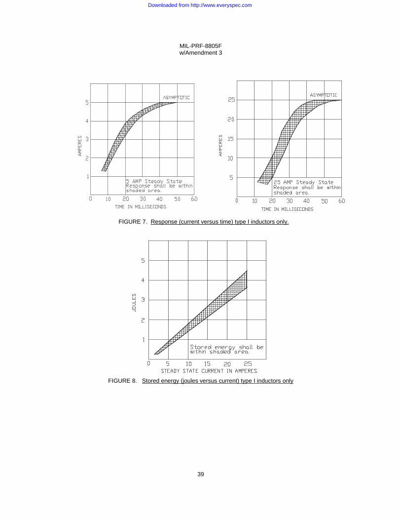
MIL-PRF-8805F w/Amendment 3
39
FIGURE 7. Response (current versus time) type I inductors only.
FIGURE 8. Stored energy (joules versus current) type I inductors only
Downloaded from http://www.everyspec.com

MIL-PRF-8805F w/Amendment 3
40
6. NOTES
(This section contains information of a general or explanatory nature that may be helpful, but is not mandatory.) 6.1 Intended use . Switches covered by this specification are intended for use in ac and dc applications. Unless otherwise specified, switches are for single phase use only and are not to be used to transfer from phase-to-phase. Contacts may be paralleled for reasons of redundancy or to reduce the total contact resistance, but they must not be paralleled for the purpose of switching currents greater than the published ratings of a single contact. Another switch with suitable contact rating must be used. These switches are military unique due to the fact that these devices must be able to operate satisfactorily in military systems under the following demanding conditions: -65°C to +350°C operating temperature range, 100 Gs of shock, and 30 Gs of sinusoidal vibration. In addition these military requirements are verified under a qualification system. Commercial components are not designed to withstand these military environmental conditions.
6.1.1 Electrical load handling capability. Switches have electrical load ratings specified by the
specification sheet. The electrical load ratings normally reflect the maximum electrical load that the switch can properly control for a specified minimum cycles of operation. In selecting a switch for a particular application electrical load, the electrical ratings of the switch should be compatible with the application load. For application loads with sufficient voltage and current to cause arcing (approximately 8 volts and 0.5 ampere), any switch with higher electrical ratings will properly control the application load. For application loads with insufficient voltage to cause arcing but with sufficient voltage to melt the contact material, (approximately .5 to 8 volts), a switch with logic load ratings should be selected. For application loads with lower voltages (below .5 volt), a switch with low level ratings should be selected. The load handling capability of an unsealed basic sensitive switch may be affected when used in sealed switch assemblies. Each contact rating and temperature characteristic must be evaluated on the sealed switch assembly.
6.1.2 Control of electronic logic circuits. Contact bounce and transfer time of most sensitive, snap action basic switches is of concern when used to control devices having very fast response time. In the case of a double throw, break-before-make, snap action switch, there is no circuit through either contact during the transfer (snap over) time. Thus, there will be a definite interval between the time one circuit opens and the other closes. Associated with circuit closure is contact bounce. When the moving contact strikes the stationary contact, the kinetic energy is converted to heat and potential energy in the form of deformation of the contacts. As a result of elastic deformation, the moving contact rebounds from the stationary contact, the contact pair being reclosed by the contact force. This can occur one or more times until bouncing ceases and the contact system reaches static equilibrium. In general, the combined transfer time and bounce time will usually not exceed five milliseconds and cause no problems on slow responding devices. On fast responding electronic logic circuits, each contact bounce may be erroneously interpreted by the circuit as a separate signal causing a false output. To compensate for the contact bounce of the switch, a ten millisecond buffering circuit is usually adequate to prevent false outputs of the logic circuit. The environmental conditions in which a switch must control a logic load level or low level electrical load may directly affect its performance in the application. Under these electrical load conditions, there is no arc present to remove contamination from the contact interfaces which prevent proper contact closure. The probability of proper contact closure under nonarcing conditions is inversely proportional to the contamination in the environment. The detrimental effects of environmental contamination can be significantly reduced by one or more of the following:
a) Enclosure: By enclosing the contacts in a sealed enclosure, the contacts are protected from
Downloaded from http://www.everyspec.com

MIL-PRF-8805F w/Amendment 3
41
the environment.
b) Contact material: The use of gold at the contact interface will prevent the formation of sulfides and oxides.
c) Contact configuration: There are two basic contact concepts specifically suited for nonarcing
electrical loads:
(1) Multiple-point contact designs to provide redundancy such as bifurcated contacts. (2) Point-to-plane or point-to-point contact designs such as wedge-shaped contacts,
crossed-cylinder contacts, or crossed-prism contacts.
6.1.3 Intermediate current capability (minimum current). The intermediate current test is used to test the low energy capability of a power switch (see 4.7.32).
6.1.4 Low level capability. Where a switch is intended to "make" and "break" a low level circuit, the low level test requirement should be used (see 4.7.33) and, if possible, a switch with sealed contact areas should be utilized.
6.1.5 Panel seal boots. Boots, when used to provide a panel seal, should be in accordance with MIL-DTL-5423, "Boots, Dust and Water Seal (For Toggle and Push-Button Switches, Circuit Breakers, and Rotary-Actuated Parts), General Specification for".
6.1.6 Intermetallic contact. The finishing of metallic areas to be placed in intimate contact by assembly presents a special problem, since intermetallic contact of dissimilar metals results in electrolytic couples which promote corrosion through galvanic action. To provide the required corrosion protection, intermetallic couples should be restricted to those permitted by MIL-STD-889.
6.1.7 Submarine application. Switches using phenolic plastics are not to be used for submarine applications.
6.1.8 Human engineering. Government contracts commonly specify that military standard components be used and that MIL-STD-1472, Human Engineering Design Criteria For Military Systems, Equipment and Facilities, applies. Due to performance and environmental requirements, or other factors, military specification switches frequently do not meet the requirements of MIL-STD-1472. To provide the desired operability, it is suggested that equipment designers select the military specification switches which can most closely conform to the human interface requirements of MIL-STD-1472 without sacrificing reliability.
Downloaded from http://www.everyspec.com

MIL-PRF-8805F w/Amendment 3
42
6.2 Acquisition requirements. 6.2.1 Category I switches (items covered by specification sheets, see 3.2.1). The acquisition document
should specify the following:
a) Title, number, and date of the specification.
b) Title, number, and date of the applicable specification sheet and the PIN.
c) Type and amount of hardware to be included with switch, if other than that specified on the applicable specification sheet.
d) ASSIST Online database at https://assist.daps.dla.mil/ should be cited in the solicitation, and if
required, the specific issue of individual documents referenced (see 2.1).
e) Packaging requirements (see 5.1)
6.2.2 Category II switches (qualified switches with minor modification, see 3.2.2). The acquisition document should specify the following:
a) Title, number, and date of this specification.
b) Title, number, and date of applicable specification sheet.
c) Type and amount of hardware to be included with switch, if other than that specified on the applicable specification sheet.
d) ASSIST Online database at https://assist.daps.dla.mil/ should be cited in the solicitation, and if
required, the specific issue of individual documents referenced (see 2.1).
e) Switch is category II.
f) PIN of qualified switch.
g) Manufacturer's PIN of modified switch (see 3.39.1b).
h) Details of the variations from the specification sheet. A copy of the drawing furnished, including the description of the variations from the specification sheet, should be sent to the agent activity specified at the bottom of page 1 of this document.
i) Inspection requirements (in addition to group A): To verify suitability of variations from
category I switches. Available manufacturing test data showing compliance may be substituted as meeting these requirements at option of contracting activity.
a. Tests to be performed (if any). b. The laboratory at which inspection is to be performed.
c. Samples and submission of data if other than that specified.
j) Packaging requirements (see 5.1).
Downloaded from http://www.everyspec.com
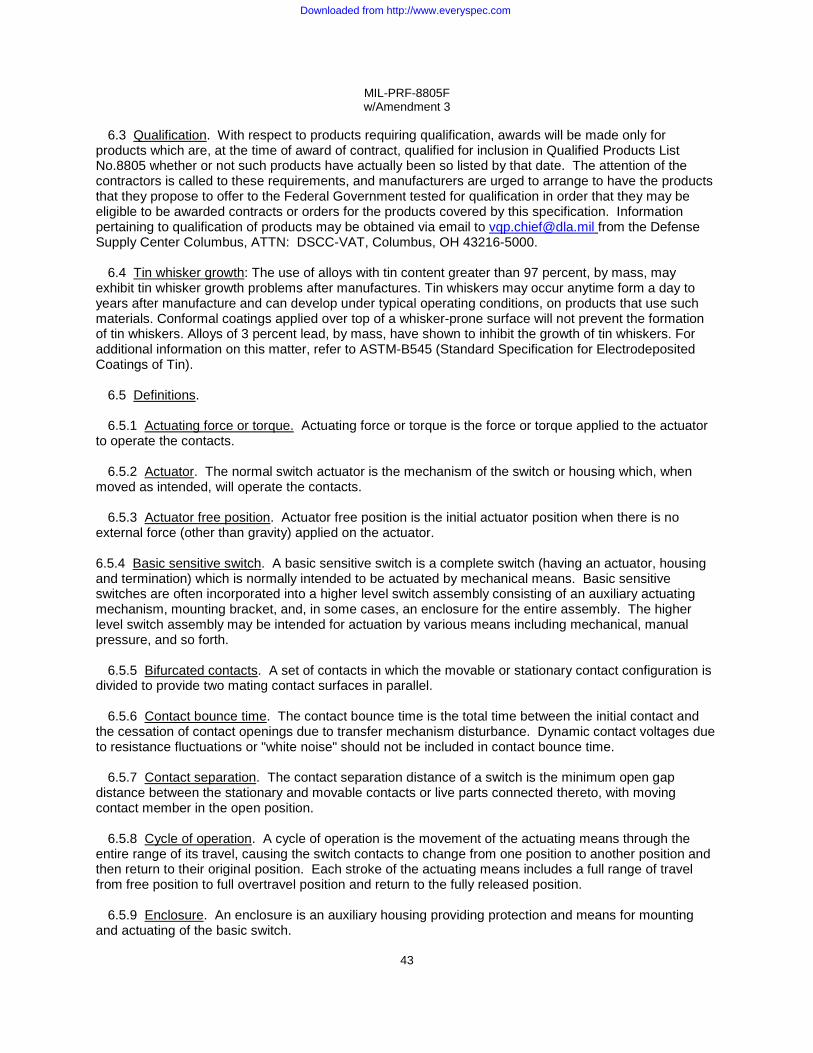
MIL-PRF-8805F w/Amendment 3
43
6.3 Qualification. With respect to products requiring qualification, awards will be made only for products which are, at the time of award of contract, qualified for inclusion in Qualified Products List No.8805 whether or not such products have actually been so listed by that date. The attention of the contractors is called to these requirements, and manufacturers are urged to arrange to have the products that they propose to offer to the Federal Government tested for qualification in order that they may be eligible to be awarded contracts or orders for the products covered by this specification. Information pertaining to qualification of products may be obtained via email to [email protected] from the Defense Supply Center Columbus, ATTN: DSCC-VAT, Columbus, OH 43216-5000.
6.4 Tin whisker growth: The use of alloys with tin content greater than 97 percent, by mass, may exhibit tin whisker growth problems after manufactures. Tin whiskers may occur anytime form a day to years after manufacture and can develop under typical operating conditions, on products that use such materials. Conformal coatings applied over top of a whisker-prone surface will not prevent the formation of tin whiskers. Alloys of 3 percent lead, by mass, have shown to inhibit the growth of tin whiskers. For additional information on this matter, refer to ASTM-B545 (Standard Specification for Electrodeposited Coatings of Tin).
6.5 Definitions.
6.5.1 Actuating force or torque. Actuating force or torque is the force or torque applied to the actuator
to operate the contacts.
6.5.2 Actuator. The normal switch actuator is the mechanism of the switch or housing which, when moved as intended, will operate the contacts.
6.5.3 Actuator free position. Actuator free position is the initial actuator position when there is no external force (other than gravity) applied on the actuator.
6.5.4 Basic sensitive switch. A basic sensitive switch is a complete switch (having an actuator, housing
and termination) which is normally intended to be actuated by mechanical means. Basic sensitive switches are often incorporated into a higher level switch assembly consisting of an auxiliary actuating mechanism, mounting bracket, and, in some cases, an enclosure for the entire assembly. The higher level switch assembly may be intended for actuation by various means including mechanical, manual pressure, and so forth.
6.5.5 Bifurcated contacts. A set of contacts in which the movable or stationary contact configuration is divided to provide two mating contact surfaces in parallel.
6.5.6 Contact bounce time. The contact bounce time is the total time between the initial contact and the cessation of contact openings due to transfer mechanism disturbance. Dynamic contact voltages due to resistance fluctuations or "white noise" should not be included in contact bounce time.
6.5.7 Contact separation. The contact separation distance of a switch is the minimum open gap distance between the stationary and movable contacts or live parts connected thereto, with moving contact member in the open position.
6.5.8 Cycle of operation. A cycle of operation is the movement of the actuating means through the
entire range of its travel, causing the switch contacts to change from one position to another position and then return to their original position. Each stroke of the actuating means includes a full range of travel from free position to full overtravel position and return to the fully released position.
6.5.9 Enclosure. An enclosure is an auxiliary housing providing protection and means for mounting and actuating of the basic switch.
Downloaded from http://www.everyspec.com

MIL-PRF-8805F w/Amendment 3
44
6.5.9.1 Unsealed switch. Unsealed switches are switches with contact areas open to the atmosphere.
6.5.9.2 Dusttight switch. Dusttight switches are switches with contact areas sealed to meet the requirements of 3.7.1.
6.5.9.3 Watertight switch. Watertight switches are switches with contact areas sealed to meet the requirements of 3.7.2.
6.5.9.4 Resilient switch. Resilient switches are switches with contact areas sealed to meet the requirements of 3.7.3.
6.5.9.5 Hermetic switch. Hermetic switches are switches with an enclosure constructed to be gas tight by complete sealing of glass or ceramic to metal or bonding metal to metal by fusion. They should meet the requirements of 3.7.4.
6.5.9.6 Splashproof switch. Splashproof switches are switches designed to seal the panel and contact areas to meet the requirements of 3.7.5.
6.5.10 Gold contacts. Contacts in which the mating surfaces are gold or gold alloy throughout the rated life of the switch. (In some instances, gold plating may be used for shelf life or multi-rating capability and is fully expected to be destroyed during life.)
6.5.11 Limit switch. A limit switch is a switch adapted to or intended for non-manual operation.
6.5.12 Manual switch assembly. A manual switch assembly is a switch assembly adapted to or intended for hand operation; explicitly to be depressed or operated manually and subject to operator variations.
6.5.13 Movement differential. Movement differential is the distance or angle through which the
actuator travels from the operating position to the releasing position.
6.5.14 Overtravel. Overtravel is the distance or angle between the operating position and the extreme position to which the actuator may be moved.
6.5.15 Overtravel force or torque. Overtravel force or torque is the force or torque applied to actuating mechanism to move the actuator to the overtravel limit position.
6.5.16 Pretravel. Pretravel is the distance or angle through which the actuator moves from free position to operating position.
6.5.17 Releasing force or torque. The releasing force or torque is the value to which the force or torque on the actuator must be reduced to permit the contacts to return to the unoperated position after operation.
6.5.18 Sensitive switch. A sensitive switch is a switch having a snap action, microgap mechanism
which is operated directly by a defined force through a defined travel.
6.5.19 Sensitive switch assembly. A sensitive switch assembly is one or more basic sensitive switches that are permanently fixed to a bracket or enclosure having a common actuating means, that is, lever, button, or plunger.
6.5.20 Silver contacts. Contacts in which the mating surfaces are silver or silver alloy throughout the rated life of the switch.
Downloaded from http://www.everyspec.com

MIL-PRF-8805F w/Amendment 3
45
6.5.21 Snap action. Snap action is that type of contact action in which speed of the moving contacts is relatively independent of the speed of the actuating mechanism.
6.6 Cross-reference. A cross-reference of MIL-PRF-8805 switches formerly covered by "MS" Standards, "AN" Air Force-Navy Aeronautical Standards, or JAN-S-63 is provided in table XIII. Unless a superseding PIN has been assigned (see table XIII), the superseding MIL-PRF-8805 specification sheet has retained the original MS or AN PIN as the item identifying number; that is, only the MS or AN document itself has been canceled, not the "MS" or "AN" PIN. Where superseding PIN's have been assigned (see table XIII), they are interchangeable with and replace the former "MS" or "SS" (JAN-S-63) PIN’s
6.7 Part or Identifying Number (PIN). See 1.3.
6.8 Subject term (key word) listing.
Controls Interlock Microswitch Trigger
6.9 Dissimilar metals (see 3.4.1.2). Dissimilar metals and compatibility couples are defined in MIL-
STD-889.
6.10 Insulation (see 3.4.2).
6.10.1 Ceramic. It is recommended that SAE-AMS-I-10 grade L422 be considered for ceramic materials.
6.10.2 Thermoplastic. It is recommended that thermoplastic materials be tested in accordance with MIL-M-24519 to the requirements specified in 3.4.2.
6.11 Rubber (see 3.4.3). It is recommended that rubber parts in accordance with A-A-59588 or MIL-R-25988 be considered for use.
6.12 Potting compounds (see 3.4.4). It is recommended that potting compounds that meet the hydrolytic stability requirements of MIL-PRF-8516, MIL-PRF-23586, MIL-I-81550, MIL-M-24041 or MIL-I-16923 be considered for use. 6.13 Environmentally preferable material. Environmentally preferable materials should be used to the maximum extent possible to meet the requirements of this specification. As of the dating of this document, the U.S. Environmental Protection Agency (EPA) is focusing efforts on reducing 31 priority chemicals. The list of chemicals and additional information is available on their website at http://www.epa.gov/osw/hazard/wastemin/priority.htm. Included in the EPA list of 31 priority chemicals are cadmium, lead, and mercury. Use of these materials should be minimized or eliminated unless needed to meet the requirements specified herein (see Section 3).
6.14 Terminal finishes and plating (see 3.5.2.1, 3.5.2.2, 3.5.2.4).
6.14.1 Gold plating. It is recommended that SAE-AMS-2422, type II, class 1 be considered for meeting the gold plating requirements of this specification.
Downloaded from http://www.everyspec.com

MIL-PRF-8805F w/Amendment 3
46
6.14.2 Tin lead plating. It is recommended that SAE-AMS-P-81728 be considered for meeting the tin lead plating requirements of this specification.
6.14.3 Nickel plating. It is recommended that SAE-AMS-QQ-P-290 be considered for meeting the nickel plating requirements of this specification.
6.14.4 Silver plating. It is recommended that ASTM B700 be considered for meeting the silver plating
requirements of this specification.
6.14.5 Hot solder dip. It is recommended that solder dip (60-40 tin lead) in accordance with EIA/IPC J-STD-006 be considered for meeting the requirements of this specification.
6.15 Changes from previous issue. The margins of this specification are marked with vertical lines
to indicate where modifications from this amendment were made. This was done as a convenience only and the Government assumes no liability whatsoever for any inaccuracies in these notations. Bidders and contractors are cautioned to evaluate the requirements of this document based on the entire content irrespective of the marginal notations.
Downloaded from http://www.everyspec.com

MIL-PRF-8805F w/Amendment 3
47
TABLE XIII. Cross-reference - Canceled "MS", "AN", and JAN-S-63 documents to MIL-PRF-8805 specification sheets.
Canceled document Superseding MIL-PRF-8805 specification sheet MS16106 MS16712 MS17974 MS17975 MS21320 MS21321 MS24331 MS24420 MS24547 MS24594 MS25008 MS25011 MS25026 MS25039 MS25040 MS25085 MS25089 MS25253 MS25314 MS25342 MS25343 MS25344 MS25345 MS25346 MS25347 MS25348 MS25349 MS25350 MS25351 MS25352 MS25353 MS25354 MS25356 MS25357 MS25380 MS25383 MS25476 MS27216 MS27217 MS27240 MS27241 MS27257 MS27259 MS27903 MS27992 MS27993 MS27994 MS27995 MS27996 MS28134 MS35061 MS35062 MS35063 AN3166 AN3167 AN3168 AN3169 AN3170 AN3215 AN3217 AN3218 AN3233
JAN-S-63
/56 /20 /35 (Canceled) /36 (Canceled) /48 /39 /40 /49 /4 /41 /31 /47 /1 ("MS" PIN's superseded by "M" PIN's) /55 ("MS" PIN's superseded by "M" PIN's) /50 (Inactive for new design) /2 /3 /27 /51 (Inactive for new design) /11 /11 /11 /14 /14 /14 /15 /15 /5 (Canceled) /16 /33 (Canceled) /17 /34 /18 /19 /52 (Canceled) /29(Inactive for new design) /7 /8 /7 /43 /30 (Canceled) /76 /83 (Canceled) /38 /44 /45 /32 /42 /53 (Inactive for new design) /28 /1 ("MS PIN superseded by "M" PIN) /1 ("MS PIN superseded by "M" PIN) /1 ("MS PIN superseded by "M" PIN) /57 (Canceled) /58 (Inactive for new design) /58 (Inactive for new design) /59 (Inactive for new design) /60 (Canceled) /61 (Canceled) /62 (Canceled) /63 (Canceled) /54 (Canceled) /1 ("SS01" through "SS07" type designations superseded by "M" PIN's)
Downloaded from http://www.everyspec.com

MIL-PRF-8805F w/Amendment 3
APPENDIX A
48
APPLICATION INFORMATION
A.1. SCOPE
A.1. Scope. This appendix provides quick-reference design and performance information on each of
the active MIL-PRF-8805 specification sheets to assist users during the equipment design process. This Appendix is not a mandatory part of the specification. The information contained herein is intended for guidance only.
A.2. APPLICABLE DOCUMENTS
A.2.1. Applicable specification sheets. See supplement 1.
A.3. APPLICATION INFORMATION
A.3.1. Data. See table A-I. The information in table A- I is in a condensed format, does not include all significant parameters, and is intended for guidance only; users are cautioned to review and evaluate the latest issue of the specification sheet, in its entirety, and determine if qualified sources are available before making a design selection. TABLE A-I Design and performance information for active MIL-PRF-8805 specification sheets.
MIL-PRF-8805 slash sheet
Switch type, circuit and
action
Terminals Seal Temperature range
Vibration range Shock
Highest 28 V dc sea level resistive
load rating
Other special design and
performance capabilities
/1
Basic, SPDT with integral
actuator, momentary
Screw and
solder
Unsealed
-55°C to +85°C 10 Hz to 500 Hz 1/
100 g 1/
2 amp Acceleration
/2
Basic, SPDT, momentary
Solder
Unsealed
-55°C to +85°C 10 Hz to 500 Hz
100 g
5 amp low level circuit
logic level bifurcated contacts
gold contacts subminiature
/3
Push button, SPDT and SPST
double break, momentary and
push-pull
Solder Dusttight -55°C to +85°C
10 Hz to 2,000 Hz 100 g and high shock (for momentary action only)
10 amp low level circuit logic level
sand and dust
/4
Basic, SPDT, momentary
Solder and PC
Unsealed -55°C to +85°C 10 Hz to 500 Hz
100 g
7 amp Gold contacts low level circuit
logic level subminiature
/7
Basic, SPDT, double break, momentary
Solder Unsealed -65°C to +125°C
10 Hz to 2,000 Hz 100 g
10 amp
/8
Basic, SPDT with integral leaf actuator, momentary
Solder and leadwire
Hermetic -65°C to +125°C
10 Hz to 2,000 Hz 100 g or high impact
4 amp Low level circuit
See footnote at end of table.
Downloaded from http://www.everyspec.com
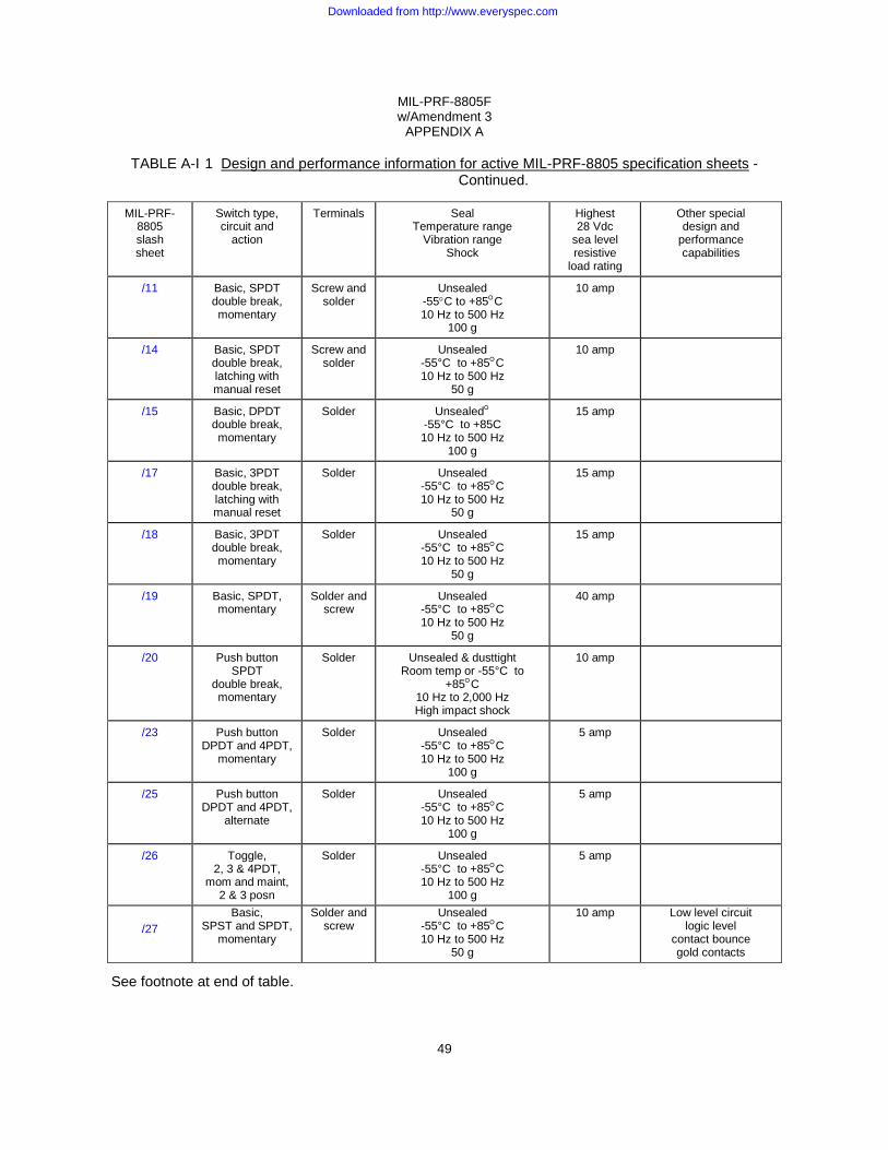
MIL-PRF-8805F w/Amendment 3
APPENDIX A
49
TABLE A-I 1 Design and performance information for active MIL-PRF-8805 specification sheets -Continued.
MIL-PRF-
8805 slash sheet
Switch type, circuit and
action
Terminals
Seal
Temperature range Vibration range
Shock
Highest 28 Vdc
sea level resistive
load rating
Other special design and
performance capabilities
/11
Basic, SPDT double break, momentary
Screw and
solder
Unsealed
-55°C to +85°C 10 Hz to 500 Hz
100 g
10 amp
/14
Basic, SPDT double break, latching with manual reset
Screw and
solder
Unsealed
-55°C to +85°C 10 Hz to 500 Hz
50 g
10 amp
/15
Basic, DPDT double break, momentary
Solder
Unsealed°
-55°C to +85C 10 Hz to 500 Hz
100 g
15 amp
/17
Basic, 3PDT double break, latching with manual reset
Solder
Unsealed
-55°C to +85°C 10 Hz to 500 Hz
50 g
15 amp
/18
Basic, 3PDT double break, momentary
Solder
Unsealed
-55°C to +85°C 10 Hz to 500 Hz
50 g
15 amp
/19
Basic, SPDT, momentary
Solder and
screw
Unsealed
-55°C to +85°C 10 Hz to 500 Hz
50 g
40 amp
/20
Push button
SPDT double break, momentary
Solder
Unsealed & dusttight
Room temp or -55°C to +85°C
10 Hz to 2,000 Hz High impact shock
10 amp
/23
Push button
DPDT and 4PDT, momentary
Solder
Unsealed
-55°C to +85°C 10 Hz to 500 Hz
100 g
5 amp
/25
Push button
DPDT and 4PDT, alternate
Solder
Unsealed
-55°C to +85°C 10 Hz to 500 Hz
100 g
5 amp
/26
Toggle,
2, 3 & 4PDT, mom and maint,
2 & 3 posn
Solder
Unsealed
-55°C to +85°C 10 Hz to 500 Hz
100 g
5 amp
/27
Basic, SPST and SPDT,
momentary
Solder and screw
Unsealed -55°C to +85°C 10 Hz to 500 Hz
50 g
10 amp Low level circuit logic level
contact bounce gold contacts
See footnote at end of table.
Downloaded from http://www.everyspec.com

MIL-PRF-8805F w/Amendment 3
APPENDIX A
50
TABLE A-I Design and performance information for active MIL-PRF-8805 specification sheets -Continued.
MIL-PRF-
8805 slash sheet
Switch type, circuit and
action
Terminals
Seal
Temperature range Vibration range
Shock
Highest 28 V dc sea level resistive
load rating
Other special design and
performance capabilities
/28
Basic, SPDT, momentary
Solder
Unsealed
-55°C to +85°C 10 Hz to 500 Hz
50 g
7.5 amp
/31
Basic, DPDT, momentary
Screw
Unsealed
-55°C to +85°C 10 Hz to 55 Hz
30 g
10 amp
/32
Basic, SPDT, momentary
Solder and leadwire
Watertight
-55°C to +85°C 10 Hz to 2,000 Hz
100 g
7 amp
Gold contacts
/34
Basic, SPDT double break, latching with manual reset
Screw and
solder
Unsealed
-55°C to +85°C 10 Hz to 500 Hz
50 g
40 amp
/38
Push button,
DPDT double break, momentary
Solder
Dusttight
-55°C to +85°C 10 Hz to 500 Hz
50 g
4 amp
Sand and dust, low level circuit,
logic level
/39
Limit,
DPDT and 4PDT, plunger,
momentary
Leadwire
Resilient
-55°C to + 85°C 10 Hz to 2,000 Hz
100 g
7 amp
Fluid resistance, hermetic terminal
header
/40
Limit,
SPDT and DPDT, single and
double break, plunger, mom
Leadwire
Resilient
-55°C to +85°C 10 Hz to 500 Hz
100 g
15 amp
Fluid resistance, hermetic terminal
header
/41
Limit,
DPDT, plunger,
momentary
Screw
Hermetic
-65 to +315°C 10 Hz to 500 Hz
100 g
5 amp
/43
Limit,
DPDT and 4PDT, plunger and
roller plunger, momentary
Leadwire
Resilient
-55°C to +85°C 10 Hz to 2,000 Hz
100 g
7 amp
Fluid resistance, low level circuit,
logic level, gold contacts,
hermetic term header
/44
Basic, SPDT, momentary
Solder and leadwire
Resilient
-55°C to +85°C or +125°C 10 Hz to 2,000 Hz
100 g
5 amp
See footnote at end of table.
Downloaded from http://www.everyspec.com

MIL-PRF-8805F w/Amendment 3
APPENDIX A
51
TABLE A-I. Design and performance information for active MIL-PRF-8805 specification sheets. - Continued.
MIL-PRF-
8805 slash sheet
Switch type, circuit and
action
Terminals
Seal
Temperature range Vibration range
Shock
Highest 28 V dc sea level resistive
load rating
Other special design and
performance capabilities
/45
Basic, SPDT, momentary
Solder and leadwire
Resilient
-55°C to +85°C or +125°C 10 Hz to 2,000 Hz
100 g
5 amp
/46
Basic, SPDT, momentary, with integral leaf actuator
Solder
Hermetic
-65°C to +125°C or +260°C and
-125°F to +350°F 10 Hz to 2,000 Hz
100 g
4 amp
Low level circuit
/47
Basic, SPDT, momentary, with integral leaf actuator
Screw
Hermetic
-55°C to +85°C 10 Hz to 500 Hz
100 g
25 amp
/48
Limit,
SPDT and DPDT single and
double break, roller lever, momentary
Leadwire
Resilient
-55°C to +85°C 10 Hz to 500 Hz
100 g
15 amp
Fluid resistance, hermetic terminal
header
/49
Limit,
SPDT and DPDT single and
double break, rotary lever,
nonself return
Leadwire
Resilient
-55°C to +85°C 10 Hz to 500 Hz
100 g
15 amp
Fluid resistance, hermetic terminal
header
/55
Foot operated microphone
switch, DPST, momentary
Screw
Unsealed or watertight
-40°C to +85°C 10 Hz to 500 Hz
50 g
0.75 amp inductive
Sand and dust
/56
Interlock,
SPDT, DPDT and 4PDT
Screw and
solder
Unsealed
-55°C to +85°C 10 Hz to 500 Hz
100 g
10 amp
/65
Limit, DPDT,
plunger, Momentary
Connector
Resilient
-55°C to +85°C 10 Hz to 2,000 Hz
High impact
5 amp
Hermetic termination
header
/68
Basic, SPDT
Solder and leadwire
Hermetic
-65°C to +125°C 10 Hz to 3,000 Hz
100 g
4 amp
Low level circuit,
Intermediate current
/70
Limit,
DPDT and 4PDT, plunger and
roller plunger, Momentary
Leadwire
Hermetic
-65°C to +85°C 10 Hz to 3,000 Hz
100 g
4 amp
Low level circuit,
Intermediate current
See footnote at end of table.
Downloaded from http://www.everyspec.com

MIL-PRF-8805F w/Amendment 3
APPENDIX A
52
TABLE A- I Design and performance information for active MIL-PRF-8805 specification sheets. Continued.
MIL-PRF-
8805 slash sheet
Switch type, circuit and
action
Terminals
Seal
Temperature range Vibration range
Shock
Highest 28 V dc sea level resistive
load rating
Other special design and
performance capabilities
/72
Limit, SPDT,
plunger, momentary
Leadwire
Hermetic
-65°C to +125°C 10 Hz to 3,000 Hz
100 g
4 amp
Low opr force,
low level circuit, intermediate current
/73
Limit, SPDT,
plunger, momentary
Leadwire
Hermetic
-65°C to +125°C 10 Hz to 8,000 Hz
100 g
4 amp
Low level circuit,
intermediate current
/74
Limit, SPDT, plunger and
roller plunger, momentary
Leadwire
Hermetic
-65°C to +125°C 10 Hz to 8,000 Hz
100 g
4 amp
Low opr force,
low level circuit, intermediate current
/76
Basic, SPDT double break, momentary
Solder
Unsealed
-65°C to +125°C 10 Hz to 2,000 Hz
100 g
8 amp
/77
Basic, DPDT double break, momentary
Solder
Unsealed
-65°C to +125°C 10 Hz to 2,000 Hz
100 g
10 amp
/80
Limit, DPDT
double break, plunger,
momentary
Lead wire
Hermetic
-55°C to +125°C 10 Hz to 2,000 Hz
200 g
5 amp
Fluid resistance
Icing Sand and dust
intermediate current
/82
Basic, SPDT, with integral leaf actuator, momentary
Solder, braze
Hermetic
-65°C to +350°C -125°F to +350°F 10 Hz to 2,000 Hz
100 g
4 amp
Low level circuit
/84
Basic, SPDT double break,
plunger or roller leaf actuator,
momentary
Solder or leadwire
Watertight
-55°C to +85°C 10 Hz to 500 Hz
100 g
10 amp
Intermediate current
/90
Basic
SPST and SPDT, momentary
Screw
Unsealed
-55°C to +85°C 10 Hz to 500 Hz
50 g
10 amp
Low opr force
See footnote at end of table.
Downloaded from http://www.everyspec.com
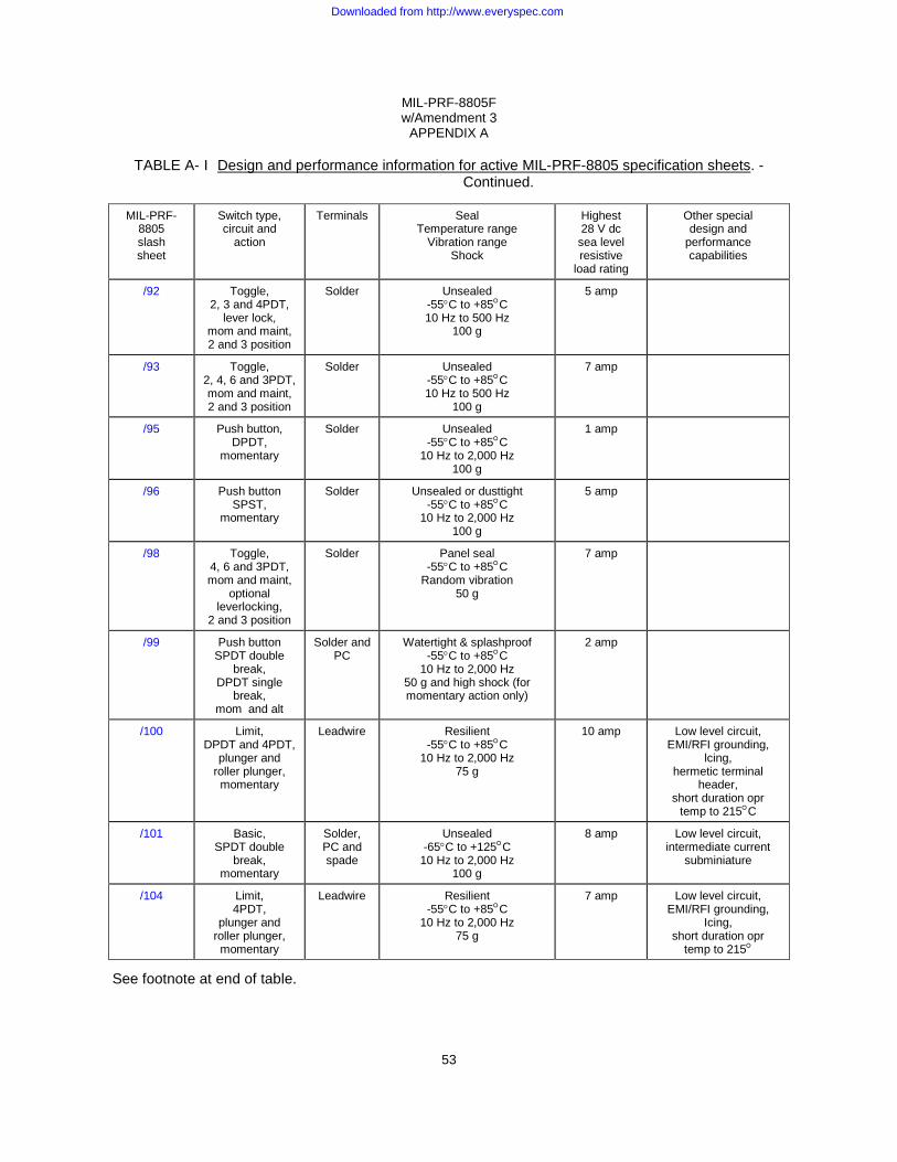
MIL-PRF-8805F w/Amendment 3
APPENDIX A
53
TABLE A- I Design and performance information for active MIL-PRF-8805 specification sheets. - Continued.
MIL-PRF-
8805 slash sheet
Switch type, circuit and
action
Terminals
Seal
Temperature range Vibration range
Shock
Highest 28 V dc sea level resistive
load rating
Other special design and
performance capabilities
/92
Toggle,
2, 3 and 4PDT, lever lock,
mom and maint, 2 and 3 position
Solder
Unsealed
-55°C to +85°C 10 Hz to 500 Hz
100 g
5 amp
/93
Toggle,
2, 4, 6 and 3PDT, mom and maint, 2 and 3 position
Solder
Unsealed
-55°C to +85°C 10 Hz to 500 Hz
100 g
7 amp
/95
Push button,
DPDT, momentary
Solder
Unsealed
-55°C to +85°C 10 Hz to 2,000 Hz
100 g
1 amp
/96
Push button
SPST, momentary
Solder
Unsealed or dusttight
-55°C to +85°C 10 Hz to 2,000 Hz
100 g
5 amp
/98
Toggle,
4, 6 and 3PDT, mom and maint,
optional leverlocking,
2 and 3 position
Solder
Panel seal
-55°C to +85°C Random vibration
50 g
7 amp
/99
Push button
SPDT double break,
DPDT single break,
mom and alt
Solder and
PC
Watertight & splashproof
-55°C to +85°C 10 Hz to 2,000 Hz
50 g and high shock (for momentary action only)
2 amp
/100
Limit,
DPDT and 4PDT, plunger and
roller plunger, momentary
Leadwire
Resilient
-55°C to +85°C 10 Hz to 2,000 Hz
75 g
10 amp
Low level circuit,
EMI/RFI grounding, lcing,
hermetic terminal header,
short duration opr temp to 215°C
/101
Basic,
SPDT double break,
momentary
Solder, PC and spade
Unsealed
-65°C to +125°C 10 Hz to 2,000 Hz
100 g
8 amp
Low level circuit,
intermediate current subminiature
/104
Limit, 4PDT,
plunger and roller plunger, momentary
Leadwire
Resilient
-55°C to +85°C 10 Hz to 2,000 Hz
75 g
7 amp
Low level circuit,
EMI/RFI grounding, Icing,
short duration opr temp to 215°
See footnote at end of table.
Downloaded from http://www.everyspec.com

MIL-PRF-8805F w/Amendment 3
APPENDIX A
54
TABLE A- I Design and performance information for active MIL-PRF-8805 specification sheets. - Continued.
MIL-PRF-
8805 slash sheet
Switch type, circuit and
action
Terminals
Seal
Temperature range Vibration range
Shock
Highest 28 V dc sea level resistive
load rating
Other special design and
performance capabilities
/106 MIL-PRF-8805
Solder
Unsealed -55°C to 205°C
10 Hz to 2,000 Hz 100 g
2 amp
High temperature, low level circuit, small differential,
travel subminiature
/107 Switches and
Switch Assemblies, Sensitive, Snap Action (Basic, Limit, Push Button and Toggle Switches), General Specification for
Solder
Dusttight
-55°C to +85°C 10 Hz to 2,000 Hz
100 g
10 amp
Intermediate current
sand and dust, large overtravel
/109 MIL-PRF-8805
Solder
Unsealed -55°C to +85°C 10 Hz to 500 Hz
100 g
7 amp
Thin base,
low level circuit, gold or silver
contact material, intermediate current
/110 Switches and
Switch Assemblies, Sensitive, Snap Action (Basic, Limit, Push Button and Toggle Switches), General Specification for
Solder and
PC
Dusttight or watertight,
-55°C to +85°C 10 Hz to 2,000 Hz
100 g
2.5 amp
Subminiature, sand and dust, low level circuit,
logic level, intermediate current
/111 MIL-PRF-8805
Solder
Unsealed -55°C to +85°C
10 Hz to 2,000 Hz 100 g
7 amp
Gold or silver
contact materials, intermediate current
/114
Switches and Switch Assemblies, Sensitive, Snap Action (Basic, Limit, Push Button and Toggle Switches), General Specification for
Leadwire
with connector
Watertight
-55°C to +85°C 10 Hz to 500 Hz
100 g
7 amp
Sand and dust
/115
Switches, Pushbutton, Momentary, Double Pole, 4 Amperes, Low Level, Sealed
Solder Watertight -40° C to +85°C 10 Hz to 500 Hz
4 amp Sand and dust Low level circuit
1/ MIL-PRF-8805/1 contacts are not monitored during vibration and shock testing.
Downloaded from http://www.everyspec.com
MIL-PRF-8805F w/Amendment 3
55
Custodians: Preparing activity:
Army - CR DLA - CC Navy - EC Air Force - 85 (Project 5930-2010-031) DLA - CC NASA - NA
Review activities:
Army - AR, AV, MI Navy - AS, MC, OS, SH Air Force - 19
NOTE: The activities listed above were interested in this document as of the date of this document. Since organizations and responsibilities can change, you should verify the currency of the information above using the ASSIST Online database at https://assist.daps.dla.mil/ .
Downloaded from http://www.everyspec.com


![INCH-POUND MIL-PRF-13830B MIL-O-13830A …eksmaoptics.com/out/fck_file/MIL-PRF-13830B[1].pdf · INCH-POUND MIL-PRF-13830B 9 January 1997 SUPERSEDING MIL-O-13830A 11 September 1963](https://static.fdocuments.net/doc/165x107/5aa212137f8b9ac67a8ca0b5/inch-pound-mil-prf-13830b-mil-o-13830a-1pdfinch-pound-mil-prf-13830b-9-january.jpg)