MIL-PRF-52109H SUPERSEDING PERFORMANCE...
22
Comments, suggestions, or questions on this document should be addressed to U.S. Army RDECOM, Tank Automotive Research, Development and Engineering Center, ATTN: RDTA-EN/STND/TRANS MS #268, 6501 E. 11 Mile Road, Warren, MI 48397-5000 or emailed to [email protected] . Since contact information can change, you may want to verify the currency of this address information using the ASSIST Online database at https://assist.daps.dla.mil . AMSC N/A FSC 4320 INCH-POUND MIL-PRF-52109H 21 December 2010 SUPERSEDING MIL-PRF-52109G 13 August 1998 PERFORMANCE SPECIFICATION PUMPING ASSEMBLIES, PORTABLE, BULK TRANSFER FUEL AND WATER PUMPING SERVICE This specification is approved for use by all Departments and Agencies of the Department of Defense. 1. SCOPE 1.1 Scope . This specification covers portable, self-priming, centrifugal pumping assemblies for fuel and water service. 1.2 Classification . The pumping assemblies will be of the following types, sizes, and classes as specified (see 6.2): Type I Pumping Assembly, Fuel Size 1 - 50 GPM capacity at 100 feet total head Size 2 - 100 GPM capacity at 80 feet total head Type II Pumping Assembly, Water Size 1 - 65 GPM capacity at 50 feet total head Class 1 - Electric-motor driven (EMD) Class 2 - Diesel-engine driven (DED) Size 2 - 125 GPM capacity at 50 feet total head Downloaded from http://www.everyspec.com
Transcript of MIL-PRF-52109H SUPERSEDING PERFORMANCE...
Comments, suggestions, or questions on this document should be addressed to
U.S. Army RDECOM, Tank Automotive Research, Development and Engineering Center,
ATTN: RDTA-EN/STND/TRANS MS #268, 6501 E. 11 Mile Road, Warren, MI 48397-5000
or emailed to [email protected]. Since contact information can
change, you may want to verify the currency of this address information using the ASSIST
Online database at https://assist.daps.dla.mil.
AMSC N/A FSC 4320
INCH-POUND
MIL-PRF-52109H
21 December 2010
SUPERSEDING
MIL-PRF-52109G
13 August 1998
PERFORMANCE SPECIFICATION
PUMPING ASSEMBLIES, PORTABLE, BULK TRANSFER
FUEL AND WATER PUMPING SERVICE
This specification is approved for use by all Departments and Agencies of the Department of
Defense.
1. SCOPE
1.1 Scope. This specification covers portable, self-priming, centrifugal pumping
assemblies for fuel and water service.
1.2 Classification. The pumping assemblies will be of the following types, sizes, and
classes as specified (see 6.2):
Type I Pumping Assembly, Fuel
Size 1 - 50 GPM capacity at 100 feet total head
Size 2 - 100 GPM capacity at 80 feet total head
Type II Pumping Assembly, Water
Size 1 - 65 GPM capacity at 50 feet total head
Class 1 - Electric-motor driven (EMD)
Class 2 - Diesel-engine driven (DED)
Size 2 - 125 GPM capacity at 50 feet total head
Downloaded from http://www.everyspec.com
MIL-PRF-52109H
2
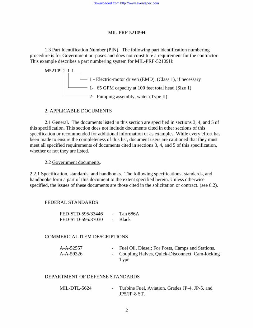
1.3 Part Identification Number (PIN). The following part identification numbering
procedure is for Government purposes and does not constitute a requirement for the contractor.
This example describes a part numbering system for MIL-PRF-52109H:
M52109-2-1-1
1 - Electric-motor driven (EMD), (Class 1), if necessary
1- 65 GPM capacity at 100 feet total head (Size 1)
2- Pumping assembly, water (Type II)
2. APPLICABLE DOCUMENTS
2.1 General. The documents listed in this section are specified in sections 3, 4, and 5 of
this specification. This section does not include documents cited in other sections of this
specification or recommended for additional information or as examples. While every effort has
been made to ensure the completeness of this list, document users are cautioned that they must
meet all specified requirements of documents cited in sections 3, 4, and 5 of this specification,
whether or not they are listed.
2.2 Government documents.
2.2.1 Specification, standards, and handbooks. The following specifications, standards, and
handbooks form a part of this document to the extent specified herein. Unless otherwise
specified, the issues of these documents are those cited in the solicitation or contract. (see 6.2).
FEDERAL STANDARDS
FED-STD-595/33446 - Tan 686A
FED-STD-595/37030 - Black
COMMERCIAL ITEM DESCRIPTIONS
A-A-52557 - Fuel Oil, Diesel; For Posts, Camps and Stations.
A-A-59326 - Coupling Halves, Quick-Disconnect, Cam-locking
Type
DEPARTMENT OF DEFENSE STANDARDS
MIL-DTL-5624 - Turbine Fuel, Aviation, Grades JP-4, JP-5, and
JP5/JP-8 ST.
Downloaded from http://www.everyspec.com
MIL-PRF-52109H
3
MIL-DTL-83133 - Turbine Fuels, Aviation, Kerosene Types, NATO
F-34 (JP-8), NATO F-35, and JP-8+100.
MIL-DTL-64159 - Coating, Water Dispersible Aliphatic Polyurethane,
Chemical Agent Resistant.
(Copies of these documents are available from https://assist.daps.dla.mil/quicksearch/ or from
Document Automation and Production Service, Building 4/D, 700 Robbins Avenue,
Philadelphia, PA 19111-5094)
2.2.2 Other Government documents, drawings, and publications. The following other
Government documents, drawings, and publications form a part of this document to the extent
specified herein. Unless otherwise specified, the issues of these documents are those cited in the
solicitation or contract.
NORTH ATLANTIC TREATY ORGANIZATION (NATO)
STANAG 1135 - Interchangeability of Fuels, Lubricants, and
Associated Products Used by the Armed Forces
of the North Atlantic Treaty Nations.
STANAG 4074 - Auxiliary Power Unit Connection for Starting
Tactical Land Vehicles.
(Copies of North Atlantic Treaty Organization (NATO) are available from NATO Blvd
Leopold III, 1110 Brussels, Belgium.)
2.3 Non-Government publications. The following documents form a part of this
document to the extent specified herein. Unless otherwise specified, the issues of these
documents are those cited in the solicitation or contract. (see 6.2).
AMERICAN NATIONAL STANDARD INSTITUTE (ANSI)
ANSI Z 535.2 - Environmental and Facility Safety Signs
(Applications for copies should be addressed to the American National Standard Institute,
25 West 43rd Street, New York, NY 10036 or from http://www.ansi.org.)
AMERICAN SOCIETY OF MECHANICAL ENGINEERS (ASME)
ASME B 1.1 - Pipe Threads, General Purpose (Inch).
ASME B 1.20.3 - Unified Inch Screw Threads (UN and UNR Thread
Form).
Downloaded from http://www.everyspec.com
MIL-PRF-52109H
4
(Copies of these documents are available online at http://www.asme.org or from American
Society of Mechanical Engineers, Orders/Inquiries, P.O. Box 2300, Fairfield, NJ 07007-2300.)
ASTM INTERNATIONAL
ASTM D 975 - Standard Specification for Diesel Fuels Oils (DoD
Adopted).
ASTM D 1655 - Standard Specification for Aviation Turbine Fuels
(DoD Adopted).
(Application for copies of ASTM publications may be obtained from the American Society for
Testing and Materials, 100 Barr Harbor Drive, PO Box C700, West Conshohocken, PA 19428-
2959 or from http://www.astm.org.)
HYDRAULIC INSTITUTE
ANSI/HI 1.1-1.5 - Centrifugal Pumps.
ANSI/HI 1.6 - Centrifugal Pump Tests.
(Application for copies should be addressed to the Hydraulic Institute, 6 Campus Drive, First
Floor North, Parsippany NJ, 07054-4406 or from http://www.pumps.org.)
NATIONAL ELECTRIC MANUFACTURERS ASSOCIATION (NEMA)
NEMA MG 1 - Motors and Generators.
(Application for copies should be addressed to the National Electrical Manufacturers
Association, 1300 N. 17th Street, Suite 1847, Rosslyn, VA 22209 or from http://www.nema.org.)
SAE INTERNATIONAL
SAE-J 513 - Refrigeration Tube Fittings (DoD Adopted).
(Application for copies should be addressed to the SAE World Headquerters,
400 Commonwealth Drive, Warrendale, PA 15096 or from http://www.sae.org.)
2.4 Order of precedence. Unless otherwise noted herein or in the contract, in the event of
a conflict between the text of this document and the references cited herein, the text of this
document takes precedence. Nothing in this document, however, supersedes applicable laws and
regulations unless a specific exemption has been obtained.
Downloaded from http://www.everyspec.com
MIL-PRF-52109H
5
3. REQUIREMENTS
3.1 First article. When specified (see 6.2), a sample shall be subjected to first article
inspection in accordance with (IAW) 4.1.1.
3.2 Materials. The materials selected for construction are the responsibility of the
contractor. The materials shall be of sufficient durability to meet all the performance
requirements as specified herein. Lead, zinc, or cadmium plating shall not be used. Type I
pumping assemblies may be constructed of any other materials suitable for fuel pumping service,
with the exceptions that the use of brass, bronze and other copper bearing alloys shall not be
permitted in contact with pumpage (fuel). Type II pumping assemblies may be constructed of
any other materials suitable for drinking water pumping service. The finished Type II pumping
assembly shall contain no materials or substances that might leak or disintegrate and cause the
pumped water to become non-potable. The materials shall have no adverse effect on the health
of personnel when used for its intended purpose. The lines and all surfaces that contact potable
water shall conform to the applicable Federal regulations for use with potable water.
3.2.1 Deterioration, prevention, and control. The manufacturer shall select materials
capable of meeting all the operational and environmental requirements specified herein. The
pumping assemblies shall be fabricated from compatible materials, inherently corrosion resistant
or treated to provide protection against corrosion and deterioration during storage and
operational conditions experienced.
3.2.1.1 Dissimilar metals. Dissimilar metals shall not be used in intimate contact with
each other unless protected against galvanic corrosion.
3.2.2 Recycled, recovered, or environmentally preferable materials. Recycled, recovered,
or environmentally preferable materials should be used to the maximum extent possible provided
that the material meets or exceeds the operational and maintenance requirements, and promotes
economically advantageous life cycle costs. Used, rebuilt, or remanufactured components shall
not be incorporated into the pump assembly.
3.3 Operational and Design Requirements.
3.3.1 Hydrostatic pressure. The pumps shall withstand an internal hydrostatic pressure of
80 pounds per square inch (psi) for Type II, and 100 psi for Type I, without rupture or distortion
to any component and without leakage through the pump, fittings, piping, or joints.
3.3.2 Capacity. The pumps shall meet the rated flow capacities indicated below using the
appropriate liquid at standard conditions, as specified by the Hydraulic Institute ANSI/HI 1.1-1.6
Centrifugal Pumps and Tests.
Downloaded from http://www.everyspec.com
MIL-PRF-52109H
6
a. Type I, Size 1 - 50 gallons per minute (GPM) with a total dynamic head of 100 feet.
b. Type I, Size 2 - 100 GPM with a total dynamic head of 80 feet.
c. Type II, Size 1 - 65 GPM with a total dynamic head of 50 feet.
d. Type II, Size 2 - 125 GPM with a total dynamic head of 50 feet.
3.3.3 Pump priming. The pump assembly shall prime automatically, after initial filling of
the case, and deliver not less than 85 % of rated flow (see 3.3.2) in not greater than 2 minutes
when operating at a static suction lift equivalent to 10 feet; at sea level and atmospheric
conditions of 29.92 inches of mercury, using water with a specific weight of 62.3 pounds per
cubic foot at 68 F.
3.3.4 Pump characteristics. All pumps shall contain drain plugs. All threaded parts shall
conform to ASME B 1.1 or ASME B 1.20.3, as applicable. Mechanical seals and wear rings
shall be suitable to intended service (see 1.2). The Type I, Size 1 pumping assembly shall be
provided with the accessories specified in the Appendix to this specification.
3.3.5 Controls.
3.3.5.1 Diesel engine. All pumping assemblies, except Type II, Size 1, Class 1 (EMD),
shall be provided with an industrial diesel engine capable of operating on a wide range of
military fuels to include JP-8, JP-5, and diesel fuels. The engine shall be furnished with, but not
limited to, the following accessories:
a. Throttle control assembly to permit manual adjustment and locking at any speed up to
the manufacturers maximum recommended speed. The control shall be labeled to indicate the
start and stop positions with a directional arrow to indicate increased speed.
b. A fuel tank shall be furnished with sufficient capacity for at least 2.5 hours of
continuous operation at the rated load. The tank shall include a hand-operated fuel shutoff valve
attached directly to the tank. The shutoff valve shall be provided with an arrow showing the
directions of valve operation. A corrosion-resistant, face-plate shall be mounted on or near the
fuel shutoff valve and shall be marked for “ON” and “OFF” positions.
c. The starting system shall be by either hand crank or recoil start. Secure storage for any
hand crank shall be provided. A low temperature assist starting system may be provided if
necessary for cold weather starting (see 4.6.2). If external electrical power is needed for any low
temperature assist starting system, then the pump assembly shall be provided with a Type 1
female receptacle per STANAG 4074 (see 6.5), which shall be used to receive external power.
There is no requirement for the pumping assembly to supply its own electrical source.
d. All diesel engines shall be furnished with a spark arresting muffler located away from
the fuel system and any other flammable pumping assembly components. The engine shall start
Downloaded from http://www.everyspec.com
MIL-PRF-52109H
7
within five minutes and develop full power within 15 minutes at all temperatures specified
herein. The engine shall deliver power at its continuous duty rating to meet the pump
performance requirements of 3.3.2.
3.3.5.2 Electric motor. The Type II, Size 1, Class 1 (EMD) pumping assembly shall be
provided with an electric motor of 208 volts-alternating-current (VAC), 60 hertz, 3 phase,
4-wire, NEMA MG 1, Design B. A 220 VAC, 60 cycle, single phase, 3-wire design will be
acceptable at the discretion of the contracting officer (see 6.2). The motor shall have a
continuous duty power rating sufficient to meet the pump performance requirements of 3.3.2.
The motor shall be a squirrel-cage, solid-shaft, induction type; totally enclosed, fan cooled, and
horizontally mounted. All electrical connections shall be watertight. A heavy duty power cord,
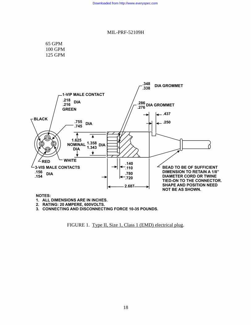
10 feet minimum, with a plug in accordance with Figure 1 shall be provided. A means to store
the power cord shall be provided.
3.3.5.3 Grounding assembly, Type I. Type I pumping assemblies shall be provided with
a ground terminal, ground rod, and ground wire. The Type I pumping assembly shall provide
complete electrical continuity throughout the unit, and shall include a metal-to-metal contact
from the pump to the ground. This includes all electrically conductive components of the unit
that the operator may come in contact with. All bonding and/or grounding connections shall be
mechanically secure and shall measure 1 (one) ohm or less. Ground rod and grounding wire
equipped with manual clamps requiring no tools shall be provided for grounding the pump
during operation. The grounding rod shall include an integral hammer and anvil, of sufficient
size to drive the rod into compact soil. The grounding rod, which may be collapsible, shall fit in
the dimensional envelope and shall be of sufficient total length to provide a minimum of
30 inches of ground penetration when in operational service configuration. Grounding wire shall
be provided on manual retracting reel mounted on the pump assembly. Grounding wire shall be
a minimum of 6 feet in length. The pump assembly shall include stowage/storage provisions for
all grounding equipment.
3.4 Interface requirements.
3.4.1 Size 1 connections. Suction and discharge connections shall face opposite sides
(180 degrees apart) of the pumping assembly, with both in the horizontal position; except the
Class 1 (EMD) that shall have both connections facing the same side, with both in the horizontal
position.
a. Suction connection shall be 1.50-inch, female, quick-disconnect couplings and gaskets
IAW A-A-59326, Class A, fitted with tethered dust plugs IAW A-A-59326/11, Class A.
b. Discharge connection shall be 1.50-inch, male, quick-disconnect couplings IAW
A-A-59326, Class A, fitted with tethered dust caps and gaskets IAW A-A-59326/10,
Class A.
3.4.2 Size 2 connections. Suction and discharge connections shall face opposite sides
Downloaded from http://www.everyspec.com
MIL-PRF-52109H
8
(180 degrees apart) of the pumping assembly, with both in the horizontal position.
a. Suction connection shall be 2-inch, female, quick-disconnect couplings and gaskets
IAW A-A-59326, Class A, fitted with tethered dust plugs IAW A-A-59326/11, Class A.
b. Discharge connection shall be 2-inch, male, quick-disconnect couplings IAW A-A-
59326, Class A, fitted with tethered dust caps and gaskets IAW A-A-59326/10, Class A.
3.4.3 Fuel compatibility. Except for Class 1 (EMD), the pumping assembly shall be
capable of operating on, all military and commercial kerosene based fuels conforming to, as a
minimum, those listed below without restrictions or kits. JP-8 shall be the designated primary
fuel for engine operation.
a. MIL-DTL-83133 (JP-8) (NATO F-34) (see 6.4)
b. MIL-DTL-5624 (JP-5) (NATO F-44) (see 6.4)
c. A-A-52557 (Diesel-military, including NATO F-54) (see 6.4)
d. ASTM-975 (Diesel-US commercial)
e. MIL-DTL-83133 (NATO F-35) (see 6.4)
f. ASTM-D 1655 (Jet A-1)
3.4.4 Dimensional and weight limits. The weight of the pumping assembly, with an
empty fuel tank and pump housing, shall not exceed 300 pounds.
3.4.4.1 Type I, Size 1. The pumping assembly, in its stored configuration, shall not
exceed 29.00 x 26.00 x 25.00 inches high.
3.4.4.2 Type I, Size 2. The pumping assembly, in its stored configuration, shall not
exceed 33.00 x 21.00 x 33.00 inches high.
3.4.4.3 Type II, Size 1, Class 1 (EMD). The pumping assembly, in its stored
configuration, shall not exceed 21.00 x 13.00 x 22.00 inches high.
3.4.4.4 Type II, Size 1, Class 2 (DED). The pumping assembly, in its stored
configuration, shall not exceed 30.00 x 25.00 x 30.00 inches high.
3.4.4.5 Type II, Size 2. The pumping assembly, in its stored configuration, shall not
exceed 37.00 x 27.00 x 31.00 inches high.
3.5 Ownership and support requirements.
3.5.1 Safety. All shafts or rotating parts shall be guarded when such parts are exposed to
contact with personnel or otherwise create a hazard. All hot surfaces of the equipment, including
exhaust components exposed to contact with personnel or that create a fire hazard, shall be fully
Downloaded from http://www.everyspec.com
MIL-PRF-52109H
9
guarded or insulated. Hot surfaces shall not be positioned near material that is flammable or that
could be melted. The fuel fill port shall be located to allow refueling without the need to open
any panels or doors. Fuel tanks shall be positioned to prevent spills or overflows from running
onto the engine, exhaust, or electrical components. Exhaust or discharges from the equipment
shall be directed away from the operator’s position. Electrical equipment shall be effectively
guarded and grounded to prevent electrical hazards.
3.5.2 Noise limits. Steady-state noise produced by the pump shall not exceed 85 decibels
(dB (A)) at the operator’s position and at occasionally occupied positions. If noise levels are
between 85 and 90 (dB(A)), or if procedures for noise suppression have been pursued and
documented to the satisfaction of the procuring activity and written permission to exceed the
85 dB(A) limit has been obtained, noise hazard signs shall be prominently displayed on the
equipment. Signs shall state:
DANGER
HEARING PROTECTION REQUIRED
WITHIN XX FEET
The word DANGER shall be on the first line and shall be white lettering on a red oval
background, which is inside a black rectangular panel in flat or lusterless colors. Other lettering
shall be in black on a white background in lusterless colors. FED-STD-595 may be used for
guidance. All lettering shall be readable at the maximum distance at which a noise level of
85 dB (A) is measured and this distance shall be inserted for XX.
3.5.2.1 Noise suppression methods. Any method of noise suppression may be used as
long as all components used by the operator are easily accessible without the use of tools. The
throttle control assembly shall be accessible and the pump assembly shall not exceed the required
noise level while operating at any set position. An enclosure shall be used as a last resort to
noise suppression; it shall be easily removable, for required field maintenance, and shall include
external provisions for carrying the pumping assembly. If the pumping assembly is enclosed,
adequate ventilation shall be provided so that the temperature inside the enclosure does not
exceed 150 F. Any noise reducing insulation used shall be non-flammable, non-combustible,
vermin proof, and shall not absorb fuel and oil.
3.5.3 Handling. The pumping assemblies shall be designed to permit easy accessibility
for maintenance and service in the field. The design shall prevent conditions hazardous to
personnel or deleterious to equipment. The pumping assembly shall have a means of being
carried by personnel. If the total weight of the pumping assembly is less than or equal to 200
pounds, the assembly shall be labeled or stenciled "MOS 92 - 2 PERSON LIFT”. If the total
weight of the pumping assembly is between 200 and up to 300 pounds, the assembly shall be
labeled or stenciled "MOS 92 - 3 PERSON LIFT”. The weight of the pumping assembly shall
be labeled or stenciled on the assembly (separate from the data plate requirement of 3.5.4). If a
noise enclosure is used, any access panels or doors shall be labeled or stenciled to indicate the
items accessed through them.
Downloaded from http://www.everyspec.com
MIL-PRF-52109H
10
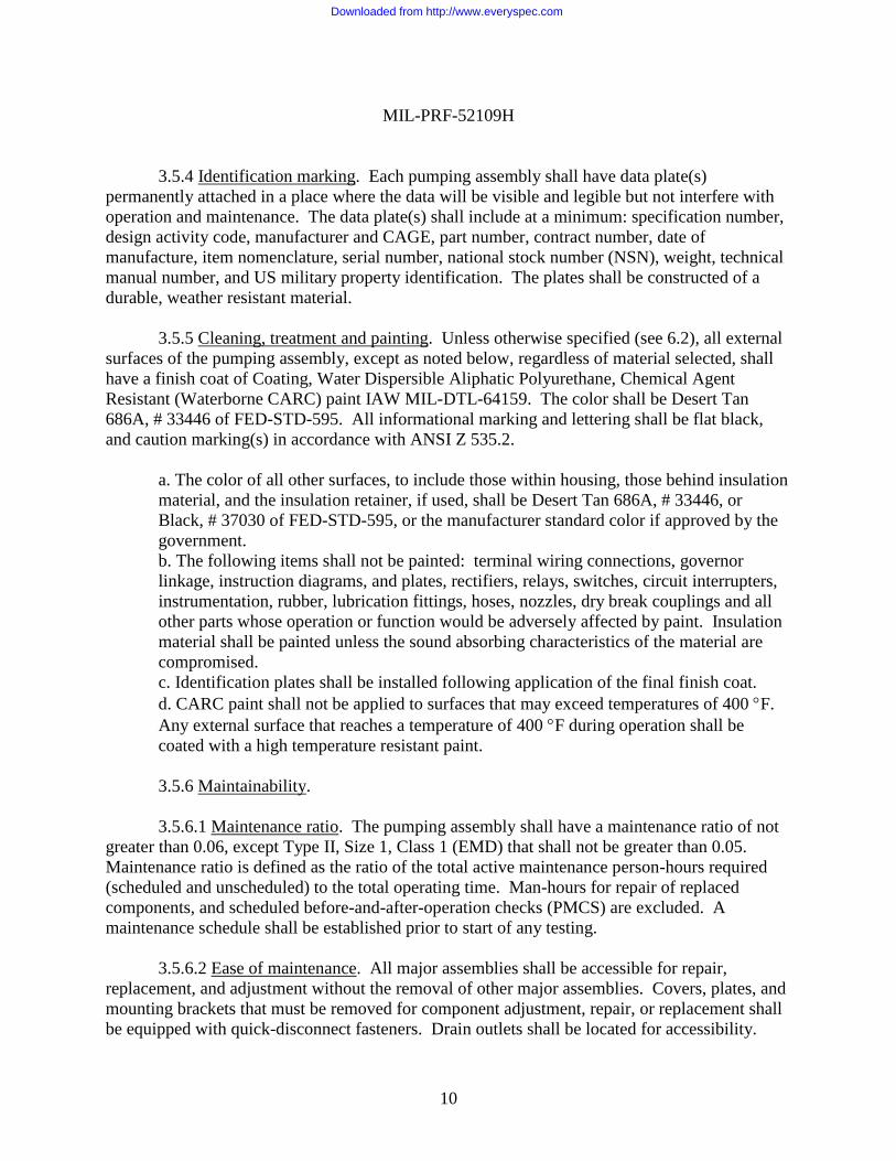
3.5.4 Identification marking. Each pumping assembly shall have data plate(s)
permanently attached in a place where the data will be visible and legible but not interfere with
operation and maintenance. The data plate(s) shall include at a minimum: specification number,
design activity code, manufacturer and CAGE, part number, contract number, date of
manufacture, item nomenclature, serial number, national stock number (NSN), weight, technical
manual number, and US military property identification. The plates shall be constructed of a
durable, weather resistant material.
3.5.5 Cleaning, treatment and painting. Unless otherwise specified (see 6.2), all external
surfaces of the pumping assembly, except as noted below, regardless of material selected, shall
have a finish coat of Coating, Water Dispersible Aliphatic Polyurethane, Chemical Agent
Resistant (Waterborne CARC) paint IAW MIL-DTL-64159. The color shall be Desert Tan
686A, # 33446 of FED-STD-595. All informational marking and lettering shall be flat black,
and caution marking(s) in accordance with ANSI Z 535.2.
a. The color of all other surfaces, to include those within housing, those behind insulation
material, and the insulation retainer, if used, shall be Desert Tan 686A, # 33446, or
Black, # 37030 of FED-STD-595, or the manufacturer standard color if approved by the
government.
b. The following items shall not be painted: terminal wiring connections, governor
linkage, instruction diagrams, and plates, rectifiers, relays, switches, circuit interrupters,
instrumentation, rubber, lubrication fittings, hoses, nozzles, dry break couplings and all
other parts whose operation or function would be adversely affected by paint. Insulation
material shall be painted unless the sound absorbing characteristics of the material are
compromised.
c. Identification plates shall be installed following application of the final finish coat.
d. CARC paint shall not be applied to surfaces that may exceed temperatures of 400 F.
Any external surface that reaches a temperature of 400 F during operation shall be
coated with a high temperature resistant paint.
3.5.6 Maintainability.
3.5.6.1 Maintenance ratio. The pumping assembly shall have a maintenance ratio of not
greater than 0.06, except Type II, Size 1, Class 1 (EMD) that shall not be greater than 0.05.
Maintenance ratio is defined as the ratio of the total active maintenance person-hours required
(scheduled and unscheduled) to the total operating time. Man-hours for repair of replaced
components, and scheduled before-and-after-operation checks (PMCS) are excluded. A
maintenance schedule shall be established prior to start of any testing.
3.5.6.2 Ease of maintenance. All major assemblies shall be accessible for repair,
replacement, and adjustment without the removal of other major assemblies. Covers, plates, and
mounting brackets that must be removed for component adjustment, repair, or replacement shall
be equipped with quick-disconnect fasteners. Drain outlets shall be located for accessibility.
Downloaded from http://www.everyspec.com
MIL-PRF-52109H
11
Corrosion resistance preventive maintenance shall be limited to routine washing, periodic
inspection and repair of accidental damage.
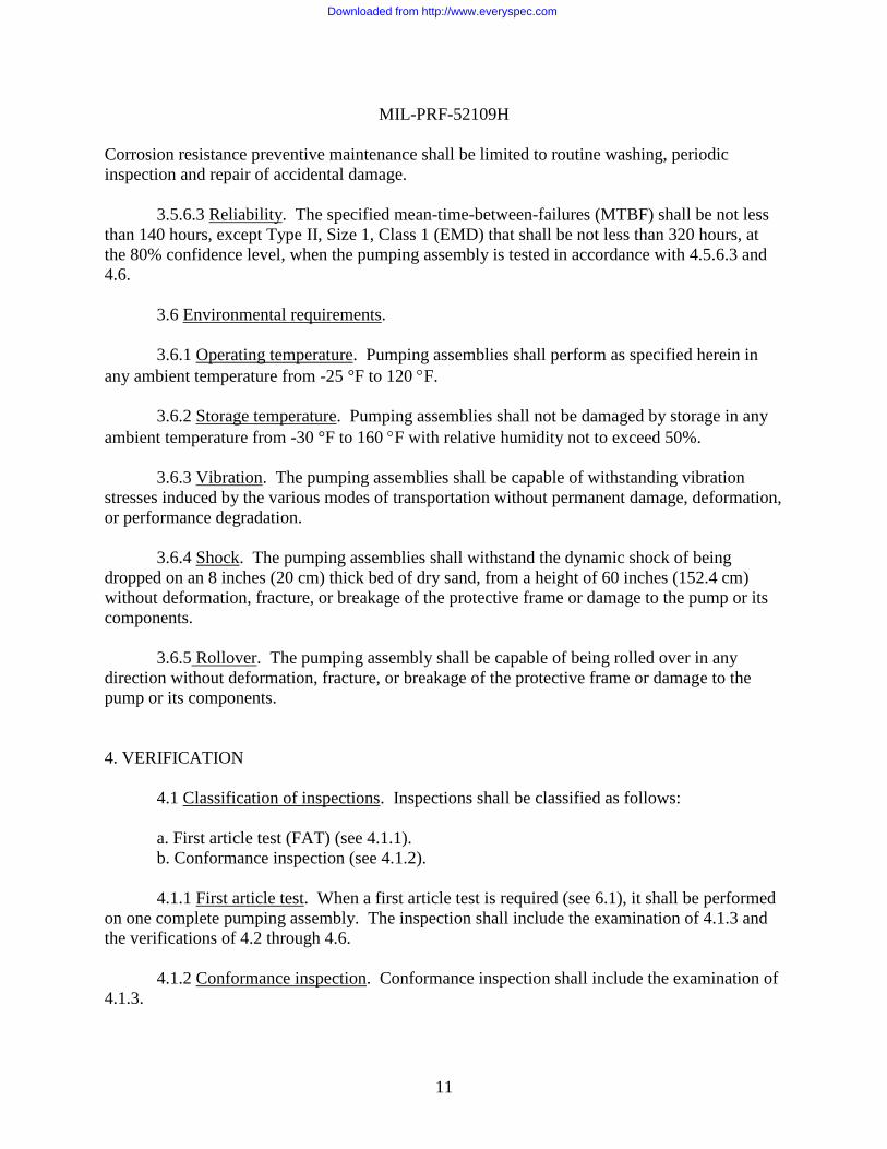
3.5.6.3 Reliability. The specified mean-time-between-failures (MTBF) shall be not less
than 140 hours, except Type II, Size 1, Class 1 (EMD) that shall be not less than 320 hours, at
the 80% confidence level, when the pumping assembly is tested in accordance with 4.5.6.3 and
4.6.
3.6 Environmental requirements.
3.6.1 Operating temperature. Pumping assemblies shall perform as specified herein in
any ambient temperature from -25 °F to 120 F.
3.6.2 Storage temperature. Pumping assemblies shall not be damaged by storage in any
ambient temperature from -30 °F to 160 F with relative humidity not to exceed 50%.
3.6.3 Vibration. The pumping assemblies shall be capable of withstanding vibration
stresses induced by the various modes of transportation without permanent damage, deformation,
or performance degradation.
3.6.4 Shock. The pumping assemblies shall withstand the dynamic shock of being
dropped on an 8 inches (20 cm) thick bed of dry sand, from a height of 60 inches (152.4 cm)
without deformation, fracture, or breakage of the protective frame or damage to the pump or its
components.
3.6.5 Rollover. The pumping assembly shall be capable of being rolled over in any
direction without deformation, fracture, or breakage of the protective frame or damage to the
pump or its components.
4. VERIFICATION
4.1 Classification of inspections. Inspections shall be classified as follows:
a. First article test (FAT) (see 4.1.1).
b. Conformance inspection (see 4.1.2).
4.1.1 First article test. When a first article test is required (see 6.1), it shall be performed
on one complete pumping assembly. The inspection shall include the examination of 4.1.3 and
the verifications of 4.2 through 4.6.
4.1.2 Conformance inspection. Conformance inspection shall include the examination of
4.1.3.
Downloaded from http://www.everyspec.com
MIL-PRF-52109H
12
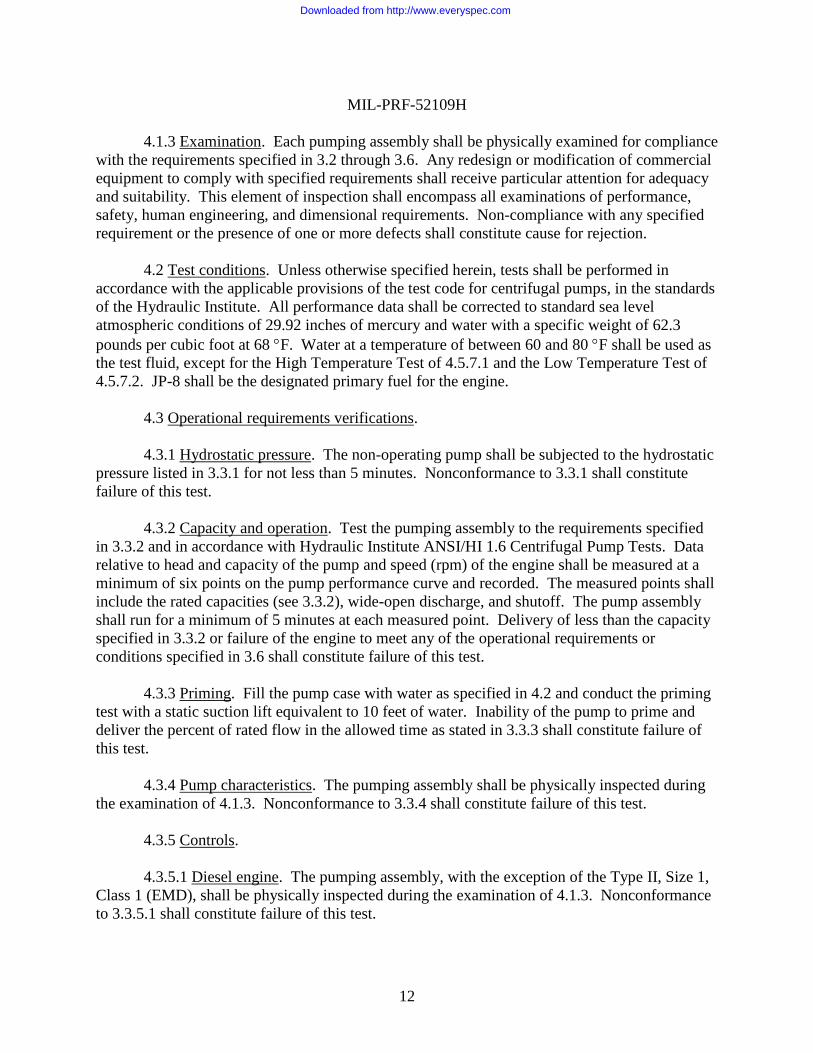
4.1.3 Examination. Each pumping assembly shall be physically examined for compliance
with the requirements specified in 3.2 through 3.6. Any redesign or modification of commercial
equipment to comply with specified requirements shall receive particular attention for adequacy
and suitability. This element of inspection shall encompass all examinations of performance,
safety, human engineering, and dimensional requirements. Non-compliance with any specified
requirement or the presence of one or more defects shall constitute cause for rejection.
4.2 Test conditions. Unless otherwise specified herein, tests shall be performed in
accordance with the applicable provisions of the test code for centrifugal pumps, in the standards
of the Hydraulic Institute. All performance data shall be corrected to standard sea level
atmospheric conditions of 29.92 inches of mercury and water with a specific weight of 62.3
pounds per cubic foot at 68 F. Water at a temperature of between 60 and 80 F shall be used as
the test fluid, except for the High Temperature Test of 4.5.7.1 and the Low Temperature Test of
4.5.7.2. JP-8 shall be the designated primary fuel for the engine.
4.3 Operational requirements verifications.
4.3.1 Hydrostatic pressure. The non-operating pump shall be subjected to the hydrostatic
pressure listed in 3.3.1 for not less than 5 minutes. Nonconformance to 3.3.1 shall constitute
failure of this test.
4.3.2 Capacity and operation. Test the pumping assembly to the requirements specified
in 3.3.2 and in accordance with Hydraulic Institute ANSI/HI 1.6 Centrifugal Pump Tests. Data
relative to head and capacity of the pump and speed (rpm) of the engine shall be measured at a
minimum of six points on the pump performance curve and recorded. The measured points shall
include the rated capacities (see 3.3.2), wide-open discharge, and shutoff. The pump assembly
shall run for a minimum of 5 minutes at each measured point. Delivery of less than the capacity
specified in 3.3.2 or failure of the engine to meet any of the operational requirements or
conditions specified in 3.6 shall constitute failure of this test.
4.3.3 Priming. Fill the pump case with water as specified in 4.2 and conduct the priming
test with a static suction lift equivalent to 10 feet of water. Inability of the pump to prime and
deliver the percent of rated flow in the allowed time as stated in 3.3.3 shall constitute failure of
this test.
4.3.4 Pump characteristics. The pumping assembly shall be physically inspected during
the examination of 4.1.3. Nonconformance to 3.3.4 shall constitute failure of this test.
4.3.5 Controls.
4.3.5.1 Diesel engine. The pumping assembly, with the exception of the Type II, Size 1,
Class 1 (EMD), shall be physically inspected during the examination of 4.1.3. Nonconformance
to 3.3.5.1 shall constitute failure of this test.
Downloaded from http://www.everyspec.com
MIL-PRF-52109H
13
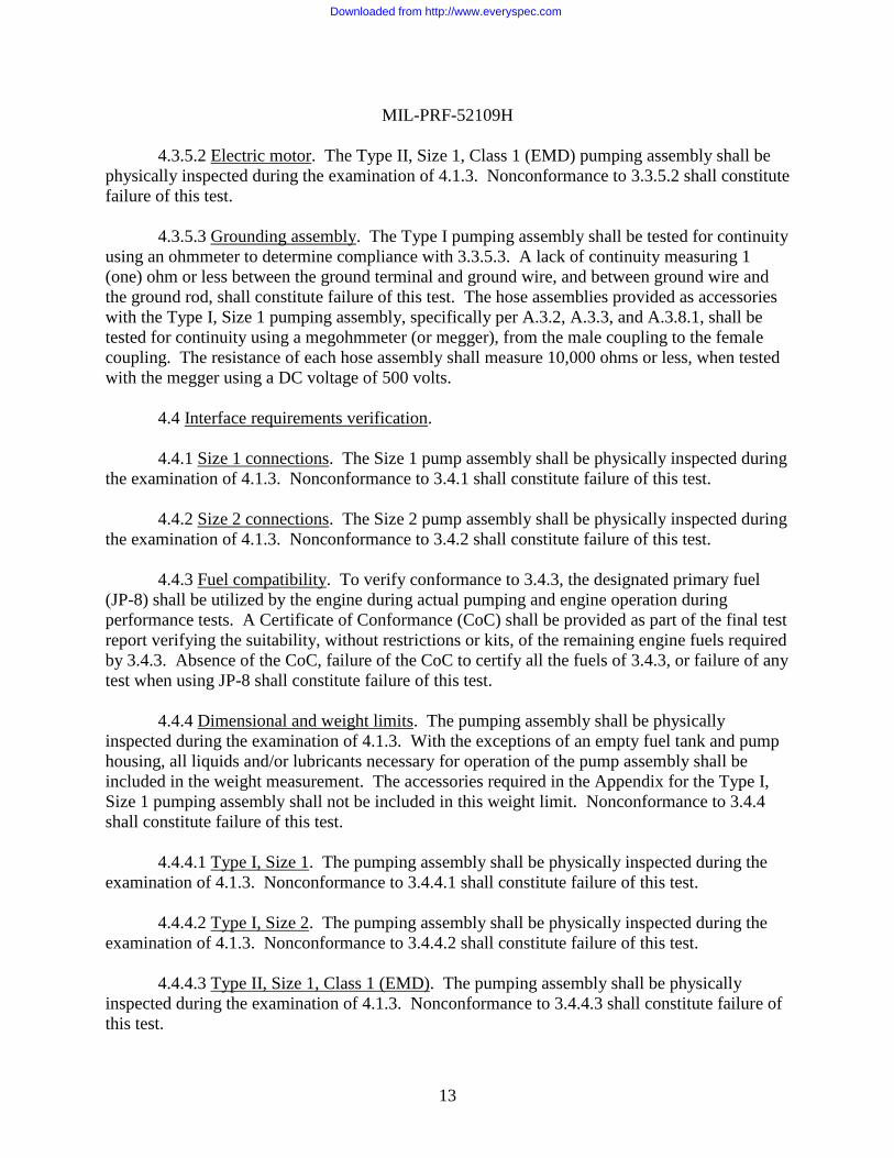
4.3.5.2 Electric motor. The Type II, Size 1, Class 1 (EMD) pumping assembly shall be
physically inspected during the examination of 4.1.3. Nonconformance to 3.3.5.2 shall constitute
failure of this test.
4.3.5.3 Grounding assembly. The Type I pumping assembly shall be tested for continuity
using an ohmmeter to determine compliance with 3.3.5.3. A lack of continuity measuring 1
(one) ohm or less between the ground terminal and ground wire, and between ground wire and
the ground rod, shall constitute failure of this test. The hose assemblies provided as accessories
with the Type I, Size 1 pumping assembly, specifically per A.3.2, A.3.3, and A.3.8.1, shall be
tested for continuity using a megohmmeter (or megger), from the male coupling to the female
coupling. The resistance of each hose assembly shall measure 10,000 ohms or less, when tested
with the megger using a DC voltage of 500 volts.
4.4 Interface requirements verification.
4.4.1 Size 1 connections. The Size 1 pump assembly shall be physically inspected during
the examination of 4.1.3. Nonconformance to 3.4.1 shall constitute failure of this test.
4.4.2 Size 2 connections. The Size 2 pump assembly shall be physically inspected during
the examination of 4.1.3. Nonconformance to 3.4.2 shall constitute failure of this test.
4.4.3 Fuel compatibility. To verify conformance to 3.4.3, the designated primary fuel
(JP-8) shall be utilized by the engine during actual pumping and engine operation during
performance tests. A Certificate of Conformance (CoC) shall be provided as part of the final test
report verifying the suitability, without restrictions or kits, of the remaining engine fuels required
by 3.4.3. Absence of the CoC, failure of the CoC to certify all the fuels of 3.4.3, or failure of any
test when using JP-8 shall constitute failure of this test.
4.4.4 Dimensional and weight limits. The pumping assembly shall be physically
inspected during the examination of 4.1.3. With the exceptions of an empty fuel tank and pump
housing, all liquids and/or lubricants necessary for operation of the pump assembly shall be
included in the weight measurement. The accessories required in the Appendix for the Type I,
Size 1 pumping assembly shall not be included in this weight limit. Nonconformance to 3.4.4
shall constitute failure of this test.
4.4.4.1 Type I, Size 1. The pumping assembly shall be physically inspected during the
examination of 4.1.3. Nonconformance to 3.4.4.1 shall constitute failure of this test.
4.4.4.2 Type I, Size 2. The pumping assembly shall be physically inspected during the
examination of 4.1.3. Nonconformance to 3.4.4.2 shall constitute failure of this test.
4.4.4.3 Type II, Size 1, Class 1 (EMD). The pumping assembly shall be physically
inspected during the examination of 4.1.3. Nonconformance to 3.4.4.3 shall constitute failure of
this test.
Downloaded from http://www.everyspec.com
MIL-PRF-52109H
14
4.4.4.4 Type II, Size 1, Class 2 (DED). The pumping assembly shall be physically
inspected during the examination of 4.1.3. Nonconformance to 3.4.4.4 shall constitute failure of
this test.
4.4.4.5 Type II, Size 2. The pumping assembly shall be physically inspected during the
examination of 4.1.3. Nonconformance to 3.4.4.5 shall constitute failure of this test.
4.5 Ownership and support requirements verifications.
4.5.1 Safety. The pumping assembly shall be physically inspected during the
examination of 4.1.3. Nonconformance to 3.5.1 shall constitute failure of this test.
4.5.2 Noise level test. Noise levels shall be measured when the pumping assembly is
operating under full load. Noise levels shall be measured at not fewer than 12 equidistant points
around the equipment including the operator's position and occasionally occupied positions. The
operator's position is defined as 24 inches horizontally from the throttle control and 12 inches
vertically above the throttle control. Occasionally occupied positions are defined as 39 inches
from the equipment and 55 inches above the ground. Noise levels shall be provided as a dB (A)
level. Failure to comply with 3.5.2 provisions shall constitute failure of this test.
4.5.2.1 Noise suppression methods. The pumping assembly shall be physically inspected
during the examination of 4.1.3. Nonconformance to 3.5.2.1 shall constitute failure of this test.
4.5.3 Handling. The pumping assembly shall be physically inspected during the
examination of 4.1.3. Nonconformance to 3.5.3 shall constitute failure of this test.
4.5.4 Identification marking. The pumping assembly shall be physically inspected during
the examination of 4.1.3. Nonconformance to 3.5.4 shall constitute failure of this test.
4.5.5 Cleaning, treatment, and painting. A Certificate of Conformance (CoC) shall be
provided verifying the application of Waterborne CARC per MIL-DTL-64159 and the color of
the coating(s). The pumping assembly shall also be physically inspected during the examination
of 4.1.3. Absence of the CoC, or nonconformance to 3.5.5 shall constitute failure of this test.
4.5.6 Maintainability.
4.5.6.1 Maintenance ratio. The maintenance ratio shall be computed from first article
testing operations of 4.5.6.3 and 4.6. Man-hours for repair of replaced components and
scheduled before-and-after operation checks are excluded. Nonconformance to 3.5.6.1 shall
constitute failure of this test.
4.5.6.2 Ease of maintenance. The pumping assembly shall be physically inspected during
the examination of 4.1.3, and the operations of 4.5.6.3 and 4.6. Nonconformance to 3.5.6.2 shall
Downloaded from http://www.everyspec.com
MIL-PRF-52109H
15
constitute failure of this test.
4.5.6.3 Reliability. The first article pumping assembly shall be operated at its rated
capacity under the standard conditions specified in 4.2. The pump assembly shall be
continuously operated for not less than 9 hours out of every 24 hours. The test shall continue for
a sufficient length of time to reach an “accept” or “reject” decision which meets the MTBF at the
80% confidence level. Total test hours shall be at least 2x and not greater than 5x the specified
MTBF. A failure is defined as any malfunction that:
a. Cannot be corrected within 30 minutes by adjustment, repair or replace using only
the maintenance tools and repair parts furnished with the equipment; or
b. May cause failure to commence operation, cessation of operation, or degradation of
performance below specified level; or
c. May damage pump assembly by continued operation; or
d. May cause a safety hazard to operating personnel.
Scheduled maintenance shall be performed in accordance with the manufacturer’s operation and
maintenance schedule. Nonconformance to 3.5.6.3 shall constitute failure of this test.
4.6 Environmental requirements verifications.
4.6.1 High temperature. The pumping assembly shall be stored at a temperature of 160
F for not less than 24 hours, relative humidity not to exceed 50%, and then the temperature
lowered to 120 F. After unit temperature stabilization at 120 F, the pumping assembly shall be
started and operated at rated capacity for not less than 3 hours. The ambient temperature during
the 3 hours of operation shall be maintained at a minimum of 120 F for the entire 3 hours.
Nonconformance to 3.6.1 or 3.6.2 shall constitute failure of this test.
4.6.2 Low temperature. The pumping assembly shall be stored at -30 F for not less than
24 hours, relative humidity not to exceed 50%, and then the temperature raised to -25 F. After
unit temperature stabilization at -25 F, the pumping assembly shall be started and operated at
rated capacity for not less than 3 hours. The ambient temperature during the 3 hours of operation
shall be maintained at a maximum of -25 F for the entire 3 hours. When water is used as the
test fluid, or pumpage, then measures shall be taken during operation to prevent the water from
dropping below the freezing point. Nonconformance to 3.6.1 or 3.6.2 shall constitute failure of
this test.
4.6.3 Vibration. The pumping assembly and any accessory boxes containing all the
accessories, if applicable, shall be subjected to a vibration test that simulates unrestrained, loose
cargo transport. The vibration test shall be conducted in a commercial package tester with a one
inch diameter orbital path at five hertz, for a period of 45 minutes. Upon conclusion of the
vibration, inspect the assembly for breakage, permanent deformation, or other damage to the
pump assembly or accessory boxes. The pumping assembly shall be started and operated at rated
capacity for not less than 3 hours. Any breakage, permanent deformation or failure of the
pumping assembly to operate as specified shall constitute failure of this test. Nicks, scrapes, and
Downloaded from http://www.everyspec.com
MIL-PRF-52109H
16
marred finish shall not be considered defects.
4.6.4 Shock. The pumping assembly shall be dropped on an 8 inches (20 cm) thick bed
of dry sand, from a height of 60 inches (152.4 cm). All drops shall be made so that the assembly
falls freely through the distance specified. The pump shall be dropped four times on each bottom
corner. Upon conclusion of the drops, inspect the assembly for breakage, permanent
deformation, or other damage to the pump assembly. The pumping assembly shall be started and
operated at rated capacity for not less than 3 hours. Breakage of the frame, or damage to the
pump or component(s), or failure of the pumping assembly to operate as specified shall
constitute failure of this test. Nicks, scrapes, and marred finish shall not be considered defects.
4.6.5 Rollover. The pumping assembly shall be placed on a flat, level concrete surface
and balanced on each bottom longitudinal edge and allowed to freely fall over onto its side. The
pump assembly shall balance and fall once for each of the bottom longitudinal edges, for a total
of four rollovers. Upon conclusion of the rollovers, inspect the assembly for breakage,
permanent deformation, or other damage to the pump assembly. The pumping assembly shall be
started and operated at rated capacity for not less than 3 hours. Breakage of the frame, or
damage to the pump or component(s), or failure of the pumping assembly to operate as specified
shall constitute failure of this test. Nicks, scrapes, and marred finish shall not be considered
defects.
5. PACKAGING
5.1 Packaging. For acquisition purposes, the packaging requirements shall be as
specified in the contract or order (see 6.2). When actual packaging of material is to be
performed by DoD personnel, these personnel need to contact the responsible packaging activity
to ascertain requisite packaging requirements. Packaging requirements are maintained by the
Inventory Control Point’s packaging activity within the Military Department or Defense Agency,
or within the Military Department’s System Command. Packaging data retrieval is available
from the managing Military Department’s or Defense Agency’s automated packaging files, CD-
ROM products, or by contacting the responsible packaging activity.
6. NOTES
(This section contains information of a general or explanatory nature that may be helpful,
but is not mandatory.)
6.1 Intended use. The pumping assemblies are intended for use as specified in 6.1.1 and
6.1.2. Because these items should operate under extreme environmental conditions (see 3.6),
they are military unique.
6.1.1 Type I. Type I pumping assemblies are intended for use in transferring
Downloaded from http://www.everyspec.com
MIL-PRF-52109H
17
hydrocarbon fuels to and from bulk storage facilities and dispensing into containers, vehicles,
and aircraft.
6.1.2 Type II. Type II pumping assemblies are intended for general purpose use in
drinking water pumping service.
6.2 Acquisition requirements. Acquisition documents will specify the following:
a. Title, number, and date of this publication
b. Type, Size, and Class of pump required (see 1.2)
c. Issue of DoDISS to be cited in the solicitation, and if required, the specific issue of
individual documents referenced (see 2.3, and A.2.3)
d. When a first article inspection is required, the number of units required, and the time
frame for submission (see 3.1)
e. When a 220V, single-phase motor is acceptable (see 3.3.5.2)
f. Color when other than as specified (see 3.5.5).
g. Packaging required (see 5.1).
6.3 Data Requirements. The contracting officer should include requirements for such
data as technical publications, instructional materials, illustrated parts lists, and contractor’s
maintenance and operation manuals to be furnished with each pumping assembly.
6.4 NATO fuel designations. STANAG 1135 describes the NATO fuel designations F-
34, F-35, F-44, and F-54.
6.5 NATO intervehicle receptacle, and cable and plug assembly. Drawing 11674728 is
provided as reference for a receptacle conforming to NATO STANAG 4074 Type 1.
6.6 Changes from previous issue. Marginal notations are not used in this revision to
identify changes with respect to the previous issue due to the extent of the changes.
6.7 Subject term (key word) listing.
centrifugal, self-priming
diesel-engine driven
electric-motor driven
potable water
50 GPM
Downloaded from http://www.everyspec.com
MIL-PRF-52109H
18
65 GPM
100 GPM
125 GPM
FIGURE 1. Type II, Size 1, Class 1 (EMD) electrical plug.
Downloaded from http://www.everyspec.com
MIL-PRF-52109H
APPENDIX A
19
ACCESSORIES FOR TYPE I, SIZE 1 PUMPING ASSEMBLY
A.1 SCOPE
A.1.1 Abstract. This appendix defines accessories for use with the Type I, Size 1
pumping assembly. The information contained herein is intended for compliance, as a
mandatory part of the specification.
A.2 APPLICABLE DOCUMENTS
A.2.1 General. The documents listed in this section are specified in section 3 of this
appendix. This section does not include documents cited in other sections of this specification or
recommended for additional information or as examples. While every effort has been made to
ensure the completeness of this list, document users are cautioned that they must meet all
specified requirements documents cited in section 3 of this appendix, whether or not they are
listed.
A.2.2 Government documents.
A.2.2.1 Specifications, standards, and handbooks. The following specifications, standards, and
handbooks form a part of this document to the extent specified herein. Unless otherwise
specified, the issues of these documents are those cited in the solicitation or contract. (see 6.2).
COMMERCIAL ITEM DESCRIPTIONS
A-A-52030 - Nozzles, Fuel and Oil Servicing, Non-automatic Shutoff and
Nozzles, Fuel Servicing, Automatic Shutoff.
A-A-59326 - Coupling Halves, Quick-Disconnect, Cam-locking Type
DEPARTMENT OF DEFENSE STANDARDS
MIL-PRF-370 - Hose and Hose Assemblies, Nonmetallic: Elastomeric,
Liquid Fuel
(Copies of these documents are available from https://assist.daps.dla.mil/quicksearch/ or from
Document Automation and Production Service, Building 4/D, 700 Robbins Avenue,
Philadelphia, PA 19111-5094)
Downloaded from http://www.everyspec.com
MIL-PRF-52109H
APPENDIX A
20
A.2.3 Non-Government publications. The following documents form a part of this
document to the extent specified herein. Unless otherwise specified, the issues of these
documents are those cited in the solicitation or contract. (see 6.2).
ASTM INTERNATIONAL
ASTM D 1149 - Ozone Resistance
(Application for copies of ASTM publications may be obtained from the American Society for
Testing and Materials, 100 Barr Harbor Drive, PO Box C700, West Conshohocken, PA 19428-
2959 or from http://www.astm.org.)
A.2.4 Order of precedence. Unless otherwise noted herein or in the contract, in the event
of a conflict between the text of this document and the references cited herein, the text of this
document takes precedence. Nothing in this document, however, supersedes applicable laws and
regulations unless a specific exemption has been obtained.
A.3 REQUIREMENTS
A.3.1 Nozzle assembly. The pumping assembly shall be equipped with two nozzle
assemblies. The nozzle assemblies shall consist of a nozzle in accordance with A-A-52030,
Type I, Size 2, Class A, Style 2, attached to a 1.50 inch, female, coupling half with gasket, fitted
with tethered dust plug in accordance with A-A-59326, Class A.
A.3.2 Suction hose. The pumping assembly shall be equipped with three of the following
suction hoses. The suction hose assembly shall be in accordance with MIL-PRF-370, Type B,
Size 05, Class 1, Style A, Material A, and 25 feet in length (Non-collapsible, 1.50 inch ID, male
and female end fitting, cam-locking end fittings, aluminum material end fitting).
A.3.3 Discharge hose. The pumping assembly shall be equipped with three of the
following discharge hoses. The discharge hose assembly shall be in accordance with MIL-PRF-
370, Type A, Size 05, Class 1, Style A, Material A, and 25 feet in length (Collapsible, 1.50 inch
ID, male and female end fitting, cam-locking end fittings, aluminum material end fitting).
A.3.4 Y connector, double male. The pumping assembly shall be equipped with a Y
connector, single female, 1.50 inch, by two male, 1.50 inch, quick disconnect coupling in
accordance with A-A-59326, Class A. The distance from the ends of the male couplings to the
center of the connector shall be 4.00 +/- 0.5 inches.
A.3.5 Y connector, double female. The pumping assembly shall be equipped with a Y
connector, single male, 1.50 inch, by two female, 1.50 inch, quick disconnect coupling in
accordance with A-A-59326, Class A. The distance from the ends of the female couplings to the
center of the connector shall be 5.00 +/- 0.5 inches. The distance from the end of the male
Downloaded from http://www.everyspec.com
MIL-PRF-52109H
APPENDIX A
21
coupling to the center of the connector shall be 3.00 +/- 0.5 inches.
A.3.6 Coupling half, quick disconnect, female. The pumping assembly shall be equipped
with a 1.50 inch, male NPT, by 1.50 inch, female, quick disconnect coupling with gasket in
accordance with A-A-59326, Class A.
A.3.7 Coupling half, quick disconnect, male. The pumping assembly shall be equipped
with a 1.50 inch, female NPT, by 1.50 inch, male, quick disconnect coupling in accordance with
A-A-59326, Class A.
A.3.8 Drum unloader assembly. The pumping assembly shall be equipped with one drum
unloader assembly that consists of the following equipment.
A.3.8.1 Hose assembly. The pumping assembly shall be equipped with two of the
following hoses. The drum unloader hoses shall be in accordance with MIL-PRF-370, Type B,
Size 05, Class 1, Style A, Material A, and 10 feet in length (Non-collapsible, 1.50 inch ID, male
and female end fitting, cam-locking end fittings, aluminum material end fitting).
A.3.8.2 Adapter, 1.50 to 2 inch. The pumping assembly shall be equipped with a 2 inch,
female, by 1.50 inch, male, quick disconnect coupling in accordance with A-A-59326, Class A.
A.3.8.3 Drum suction stub. The pumping assembly shall be equipped with one drum
suction stub consisting of a 1.50 inch, female NPT by 1.50 inch, 90, male adapter half with
tethered dust cap, in accordance with A-A-59326, Class A. It shall be attached to a 36.50 inch x
1.50 inch pipe of the same material, with a 1.50 inch male NPT thread. The opposite pipe end
shall terminate at a 305angle cut.
A.3.9 Storage chest. The pumping assembly shall be equipped with two storage chests.
All listed Type I, Size 1 accessories shall fit within the two storage chests. The use of cardboard
or wood in the storage chests shall be prohibited. Each storage chest shall be not greater than 44
inches long, 20 inches wide and 17 inches high. Each storage chest shall have a minimum of
four carrying handles, and when loaded, weigh not greater than 140 pounds.
A.3.9.1 Identification marking. Each storage chest shall have data plate(s) permanently
attached in a place where the data will be visible and legible but not interfere with operation and
maintenance. A minimum of one data plate shall include, at a minimum: Name of the system the
storage chest is associated with (eg. 50 gpm pump and NSN), Chest # of 2, Weight, and packing
list of enclosed components. A separate date plate shall also include a label for weight lifting
requirement (eg. Weight in pounds, “MOS 92 - 2 person lift”). The data plates shall be
constructed of a durable, weather resistant material.
Downloaded from http://www.everyspec.com
MIL-PRF-52109H
22
Custodians: Preparing activity:
Army - AT Army - AT
Navy - SH
Air Force - 99
Review activity: (Project 4320-2011-001)
DLA - CC
NOTE: The activities listed above were interested in this document as of the date of this
document. Since organizations and responsibilities can change, you should verify the currency of
the information above using the ASSIST database at https://assist.daps.dla.mil/.
Downloaded from http://www.everyspec.com