MIL-PRF-32479 28 FEB 2014 SUPERSEDING PEFORMANCE …
36
Comments, suggestions, or questions on this document should be addressed to: WR-ALC/AFLCMC/WNZEC, Robins AFB GA 31098-1813. Since contact information can change, you may want to verify the currency of this address information using the ASSIST Online database at https://assist.dla.mil . AMSC N/A FSC 1730 DISTRIBUTION STATEMENT A. Approved for public release; distribution is unlimited. INCH-POUND MIL-PRF-32479 28 FEB 2014 SUPERSEDING MIL-T-26225B (USAF) 01 MAR 1995 MIL-T-26310A (USAF) 08 JUL 1959 (See 6.3) PEFORMANCE SPECIFICATION FOR TRAILERS, LIFT - AIRCRAFT AND MISSILE ENGINE This specification is approved for use by the Department of the Air Force and is available for use by all Departments and Agencies of the Department of Defense. 1. SCOPE 1.1 Scope. This specification covers Trailers, Lift - Aircraft and Missile Engine; herein referred to as, Aircraft and Missile Engine Lift Trailers. The aircraft and missile engine lift trailers are designated ETU-8/E (T4000) and ETU-9/E (T4100), for removal, transfer and installation of aircraft engines and comparable heavy aircraft and missile components. This specification consolidates the requirements of both aircraft and missile trailers into one universal trailer with two different types. 1.2 Classification. Engine trailers are one of the following types as specified (see 6.2). Type 1 – ETU-8/E, (T4000), 8,000 pound capacity Type 2 – ETU-9/E, (T4100), 10,000 pound capacity These requirements are generally the same, and the differences are tabulated in Table II as specified herein. Downloaded from http://www.everyspec.com
Transcript of MIL-PRF-32479 28 FEB 2014 SUPERSEDING PEFORMANCE …

Comments, suggestions, or questions on this document should be addressed to: WR-ALC/AFLCMC/WNZEC, Robins AFB GA 31098-1813. Since contact information can change, you may want to verify the currency of this address information using the ASSIST Online database at https://assist.dla.mil . AMSC N/A FSC 1730 DISTRIBUTION STATEMENT A. Approved for public release; distribution is unlimited.
INCH-POUND MIL-PRF-32479 28 FEB 2014 SUPERSEDING MIL-T-26225B (USAF) 01 MAR 1995 MIL-T-26310A (USAF) 08 JUL 1959 (See 6.3)
PEFORMANCE SPECIFICATION
FOR
TRAILERS, LIFT - AIRCRAFT AND MISSILE ENGINE
This specification is approved for use by the Department of the Air Force and is available for use by all Departments and Agencies of the Department of Defense.
1. SCOPE 1.1 Scope. This specification covers Trailers, Lift - Aircraft and Missile Engine; herein referred to as, Aircraft and Missile Engine Lift Trailers. The aircraft and missile engine lift trailers are designated ETU-8/E (T4000) and ETU-9/E (T4100), for removal, transfer and installation of aircraft engines and comparable heavy aircraft and missile components. This specification consolidates the requirements of both aircraft and missile trailers into one universal trailer with two different types. 1.2 Classification. Engine trailers are one of the following types as specified (see 6.2).
Type 1 – ETU-8/E, (T4000), 8,000 pound capacity Type 2 – ETU-9/E, (T4100), 10,000 pound capacity
These requirements are generally the same, and the differences are tabulated in Table II as specified herein.
Downloaded from http://www.everyspec.com

MIL-PRF-32479
2
1.3 Part or Identifying Number (PIN). The following PIN procedure is for Government purposes and does not constitute a requirement for the contractor. The PINs to be used for these Aircraft and Missile Engine Lift Trailers acquired to this specification are created as follows: M prefix: Specification number: 32479 2. APPLICABLE DOCUMENTS 2.1 General. The documents listed in this section are specified in sections 3 and 4 of this specification. This section does not include documents cited in other sections of this specification or recommended for additional information or as examples. While every effort has been made to ensure the completeness of this list, document users are cautioned that they must meet all specified requirements of documents cited in sections 3 and 4 of this specification, whether or not they are listed. 2.2 Government documents. 2.2.1 Specifications, standards, and handbooks. The following specifications, standards, and handbooks form a part of this document to the extent specified herein. Unless otherwise specified, the issues of these documents are those cited in the solicitation or contract. FEDERAL STANDARDS
FED-STD-595/26173 Gray, Semigloss FED-STD-595/31136 Red, Lusterless FED-STD-595/37038 Black, Lusterless
COMMERCIAL ITEM DESCRIPTIONS
A-A-52464 Coupler, Drawbar, Ring; Light Duty, 60,000 Lb GVW; Offset (Taper Shank), 60,000 Lb GVW; and Heavy Duty 120,000 Lb GVW
DEPARTMENT OF DEFENSE SPECIFICATIONS
MIL-PRF-23377 Primer Coatings: Epoxy, High-Solids MIL-PRF-26915 Primer Coating, for Steel Surfaces
Type: 1 - ETU-8/E, 8,000 pound capacity Type: 2 - ETU-9/E, 10,000 pound capacity
M 32479 - 2
Downloaded from http://www.everyspec.com

MIL-PRF-32479
3
MIL-DTL-53030 Primer Coating, Epoxy, Water Based, Lead and Chromate Free
MIL-DTL-81706 Chemical Conversion Materials for Coating Aluminum and Aluminum Alloys
MIL-PRF-85285 Coating: Polyurethane, Aircraft and Support Equipment DEPARTMENT OF DEFENSE STANDARDS
MIL-STD-130 Identification Marking of U.S. Military Property MIL-STD-810 Environmental Engineering Considerations and
Laboratory Tests MIL-STD-882 Standard Practice System Safety MIL-STD-889 Dissimilar Metals MIL-STD-1366 Interface Standard for Transportability Criteria MIL-STD-1472 Human Engineering MIL-STD-1791 Designing for Internal Aerial Delivery in Fixed Wing
Aircraft (Copies of these documents are available online at http://quicksearch.dla.mil/ or from the Standardization Document Order Desk, 700 Robbins Avenue, Building 4D, Philadelphia PA 19111-5094.) 2.2.2 Other Government documents, drawings, and publications. The following other Government documents, drawings, and publications form a part of this document to the extent specified herein. Unless otherwise specified, the issues of these documents are those cited in the solicitation or contract. AIR FORCE INSTRUCTION (AFI)
AFI 32-7086 Hazardous Materials Management (Copies of this document are available online at http://www.e-publishing.af.mil/.) TEST OPERATIONS PROCEDURE (TOP)
TOP 2-2-800 Center of Gravity (Copies of this document can be obtained from https://vdls.atc.army.mil/.) 2.3 Non-Government publications. The following documents form a part of this document to the extent specified herein. Unless otherwise specified, the issues of these documents are those cited in the solicitation or contract. AMERICAN WELDING SOCIETY (AWS)
D1.1/D1.1M Structural Welding Code–Steel
Downloaded from http://www.everyspec.com
MIL-PRF-32479
4
D1.2/D1.2M Structural Welding Code–Aluminum (Application for copies should be addressed to American Welding Society, 550 N.W. LeJeune Road, Miami FL 33126 or on-line at http://www.aws.org.) SOCIETY OF AUTOMOTIVE ENGINEERS (SAE)
AS8090 Mobility, Towed Aerospace Ground Equipment, General Specification For
(Application for copies should be addressed to SAE International, 400 Commonwealth Drive, Warrendale PA 15096 or on-line at http://www.sae.org.) TIRE AND RIM ASSOCIATION (TRA)
TRA YEAR BOOK Tire and Rim Association, Year Book (Application for copies should be addressed to The Tire and Rim Association, Inc., 175 Montrose West Ave., Suite 150, Copley OH 44321 or on-line at http://www.us-tra.org .) 2.4 Order of precedence. Unless otherwise noted herein or in the contract, in the event of a conflict between the text of this document and the references cited herein, the text of this document takes precedence. Nothing in this document, however, supersedes applicable laws and regulations unless a specific exemption has been obtained. 3. REQUIREMENTS 3.1 First article. When specified (see 6.2), one sample of each type (as applicable) shall be subjected to first article inspection in accordance with 4.2. 3.2 Engine trailers description. The engine trailer is a mobile, hydraulically self-supporting trailer, which is made up of a set of rails connected to an elevating main frame by a hydraulically controlled linkage system. A towbar forward and a pintle hook aft provide means of transporting the trailers individually or in groups. 3.3 Design and construction. The trailers shall be designed and constructed in accordance with all applicable European Union (EU) requirements in order to have the “CE” marking affixed (see 3.3.3.1). They shall be designed and constructed so that no parts will work loose in service, and to withstand the strains, jars, vibrations, and other conditions incident to shipping, storage, installation, and service. They shall be weatherproof and designed to prevent the intrusion of water, sand, and dust into critical operating components. 3.3.1 Materials, protective coatings, and finish. 3.3.1.1 Recycled, recovered, or environmentally preferable materials. Recycled, recovered, or environmentally preferable materials should be used to the maximum extent possible provided
Downloaded from http://www.everyspec.com

MIL-PRF-32479
5
that the material meets or exceeds the operational and maintenance requirements, and promotes economically advantageous life cycle costs. However, used, rebuilt, or refurbished items shall not be provided. 3.3.1.2 Protective coatings. Materials that deteriorate when exposed to sunlight, weather, or operational conditions normally encountered during the service life of the item shall not be used or shall have means of protection against such deterioration that does not prevent compliance with the performance requirements specified herein. Protective coatings that chip, crack, or scale with age or extremes of climatic conditions or when exposed to heat shall not be used. Exposed surfaces of fasteners, handles, and fittings shall also be primed and painted. 3.3.1.2.1 Surface preparation and pretreatment. Surface preparation and pretreatment shall be in accordance with the respective primer and topcoat specifications. Structures shall be cleaned, degreased, and scuffed or blasted prior to priming; primer shall be applied before any oxidation or rusting occurs. Aluminum surfaces shall have MIL-DTL-81706, Type II, Class 1A, chemical conversion coating applied in accordance with the manufacturer’s directions prior to priming.
3.3.1.2.2 Primer. Raw metal edges, to include fastener and drain holes, shall be coated with primer before applying topcoat. 3.3.1.2.2.1 Ferrous surfaces. Ferrous structures and surfaces shall be primed with a water reducible zinc rich primer in accordance with MIL-PRF-26915, Type II, Class B; this shall be followed, within four hours, by a coat of MIL-DTL-53030 intermediate primer in a wet-to-wet primer application. This two part primer system shall yield a dry-film thickness of 2.0-2.5 mils for the zinc primer and 0.9 to 1.1 mils for the intermediate primer. The two-primer system shall be allowed to dry and fully cure in accordance with the primer manufacturer's directions prior to top coating. 3.3.1.2.2.2 Aluminum and mixed aluminum and ferrous surfaces. Aluminum and mixed aluminum and ferrous structures and surfaces shall be primed with an epoxy primer, Type II, Class N of MIL-PRF-23377. This single part primer system shall yield a dry-film thickness of 0.6 to 0.8 mils. 3.3.1.2.3 Topcoat. Topcoat shall be polyurethane in accordance with Type I, Class H of MIL-PRF-85285. Neither Chemical Agent Resistant Coating (CARC) nor powder coating shall be used. Topcoat shall be applied to a dry film thickness of 1.6 to 2.4 mils in all instances, regardless of the primer system utilized. The coating shall be free from runs, sags, orange peel, or other defects. 3.3.1.3 Dissimilar metals. Dissimilar metals, as defined in MIL-STD-889, shall not be in contact with each other. Metal plating or metal spraying of dissimilar base metals to provide electromotively compatible abutting surfaces is acceptable. The use of dissimilar metals only when separated by suitable insulating material is permitted, except in systems where bridging of insulation materials by an electrically conductive fluid can occur. Sealants or gel type gasket materials shall be used between faying surfaces and butt joints.
Downloaded from http://www.everyspec.com
MIL-PRF-32479
6
3.3.1.4 Finish. The exterior finish color of the engine trailer shall be Semigloss Gray, Color Number 26173 of FED-STD-595. 3.3.1.5 Exclusion of water. The design of the trailer shall be such as to prevent water leaking into, or being driven into, any part of the trailer interior when either in an operating or travelling configuration. All windows, doors, panels, covers, etc., shall be provided with sealing arrangements such that the entry of water is minimized when these items are correctly closed. Particular care shall be taken to prevent wetting of equipment, insulation, and sound proofing materials. Sharp corners and recesses shall be avoided so that moisture and solid matter cannot accumulate to initiate localized attack. Sealed floors with suitable drainage shall be provided for storage compartments, engine compartments, and other areas in the trailer that could collect and retain water. 3.3.1.5.1 Fluid traps and faying surfaces. There shall be no fluid traps on the engine trailer. Faying surfaces of all structural joints, except welded joints, shall be sealed to preclude fluid intrusion. 3.3.1.5.2 Ventilation. Ventilation shall be sufficient to prevent moisture retention and buildup. 3.3.1.5.3 Drainage. Drain holes shall be provided to prevent collection or entrapment of water or other unwanted fluid in areas where exclusion is impractical. All designs shall include considerations for the prevention of water or fluid entrapment and ensure that drain holes are located to effect maximum drainage of accumulated fluids. The number and location of drain holes shall be sufficient to permit drainage of all fluids when the unit is in a 10 degree incline in any plane. The minimum size of the drain holes shall be 0.25 inch. 3.3.2 Markings. All external devices which require an operational or maintenance interface shall be marked in accordance with MIL-STD-130. Markings shall be applied with decals and shall be 1-inch high block letters unless prohibited by the available space. In such cases, the markings shall be the largest size possible. Markings, Information/Caution shall be Lusterless Black, Color Number 37038 of FED-STD-595, and Markings, Warning/Danger shall be Lusterless Red, Color Number 31136 of FED-STD-595. The center of gravity of the trailer shall be stenciled on the unit within 1.0 inch of the calculated center of gravity. 3.3.3 Identification and information plates. 3.3.3.1 Identification plate. An identification plate in accordance with MIL-STD-130 shall be securely attached to the engine trailer in a readily accessible location. The identification plate shall contain the following information: nomenclature, part number, serial number, date of manufacture, manufacturer’s name, Commercial and Government Entity (CAGE) code, date of warranty expiration, and National Stock Number (NSN). The engine trailer and any of its components for which the Government’s unit cost is more than $5,000, is serially managed, or the procuring agency determines is mission essential, shall have Unique Identification (UID) (also known as Item Unique Identification (IUID)) information permanently affixed on or near the respective identification plate(s), marked in accordance with MIL-STD-130. UID information shall be included as both a bar code and human readable markings. The “CE”
Downloaded from http://www.everyspec.com

MIL-PRF-32479
7
marking shall be affixed in accordance with EU requirements on or adjacent to the identification plate. 3.3.3.2 Transportation data plate. A transportation data plate shall be securely attached to the engine trailer in a readily accessible location. The plate shall contain at least the following information:
a. Side and rear silhouette views of the engine trailer. b. Horizontal and vertical location of the center of gravity of the engine trailer in air
transportable configuration, marked on the silhouette views. c. Shipping weight. d. Loading cubage. e. Overall height, width, and length. f. Front and rear axle loads. g. Tie down information.
3.3.4 Miscellaneous design requirements. 3.3.4.1 Commercial parts. Commercially available components shall be utilized throughout the design of the trailer. Commercially available components shall be defined as components that can be obtained from more than one manufacturer with standard interface and dimension characteristics. For utility components such as screws, bolts, nuts, and cotter pins it is required that standard parts (MS or AN) be utilized to the maximum extent possible. 3.3.4.2 Specially manufactured components. 3.3.4.2.1 Cast components. Cast components are permitted in the design of the trailer. Impact loading, toughness, fatigue resistance, and wear resistance are some examples of properties to consider in the casting component design. 3.3.4.3 Interchangeability. Fabrication and assembly processes and techniques shall be such as to support, without degradation, the interchangeability requirements of the design. Like units, assemblies, subassemblies, and parts shall be physically and functionally interchangeable without modification of such items or of the equipment. 3.3.5 Maintainability. The engine trailers shall be designed for maintainability in accordance with 5.9 through 5.9.18 of MIL-STD-1472; forces shall not exceed those specified for both males and females.
Downloaded from http://www.everyspec.com

MIL-PRF-32479
8
3.3.6 Operators. The trailers shall be designed such that a maximum number of three operators are needed, which are two pumpers and one spotter. The desired number of operators is one pumper and one spotter. 3.3.7 Service life. The trailers shall be designed for a minimum service life of 25 years. 3.3.8 Safety. 3.3.8.1 Environment, Safety, and Occupational Health (ESOH). 3.3.8.1.1 System safety. The design of the engine trailer shall not contain any system safety mishap risk categories greater than medium as defined in Table III of MIL-STD-882. 3.3.8.1.2 Hazardous material. The design shall minimize and control hazards associated with the inclusion or use of hazardous or toxic materials (including hexavalent chromium) and the generation of toxic or noxious gases. The engine trailer shall not generate or use Class I or Class II Ozone Depleting Substances (ODS) during operation, maintenance, or disposal. For the purposes of this requirement, the Class I ODS and controlled substances identified in Chapter 4 of AFI 32-7086 shall not be used in any system, component, or process. 3.3.8.2 Component protection. All space in which work is performed during operation, service, and maintenance shall be free of hazardous protrusions, sharp edges, or other features which may cause injury to personnel. All rotating and reciprocating parts and all parts subject to high operational temperatures or subject to being electrically energized, that are of such nature or so located as to be hazardous to personnel, shall be guarded or insulated to eliminate the hazard. All wires, cables, tubes, and hoses shall be supported and protected to minimize chafing and abrasion and shall be located so as to provide adequate clearance from moving parts and high operational temperatures. Grommets shall be provided wherever wires, cables, tubes, or hoses pass through bulkheads, partitions, or structural members. 3.3.8.3 Foolproofness. Where improper installation of an item causes a malfunction, an asymmetric mounting system shall be provided, where practical, to ensure proper mounting of the item. 3.3.8.4 Foreign object damage (FOD). All loose metal parts, such as pins or connector covers, shall be securely attached to the engine trailer with wire ropes or chains. "Dog tag" style beaded chains shall not be provided. Removable panels, if provided, shall be attached with captive fasteners. Tire valve stem caps shall be made of plastic. 3.3.9 Human engineering. The engine trailers shall be designed in accordance with MIL-STD-1472 for ease of operation, inspection, and maintenance, including the use of arctic mittens and Mission-Oriented Protective Posture (MOPP) Level 4 Chemical Warfare Gear. 3.3.10 Fastening devices. All screws, bolts, nuts, pins, and other fastening devices shall be properly designed, manufactured, and installed with adequate means of preventing loss of torque or adjustment. Cotter pins, lock washers, or nylon patches shall not be used for this purpose,
Downloaded from http://www.everyspec.com

MIL-PRF-32479
9
except for the attachment of trim items or as provided in commercial components. Tapped threads shall have a minimum thread engagement in accordance with Table I.
TABLE I. Minimum thread engagement.
Material
Minimum Thread Engagement
Steel 1.0 times the nominal fastener diameter Cast iron, brass, or bronze 1.5 times the nominal fastener diameter Aluminum, zinc, or plastic 2.0 times the nominal fastener diameter
3.4 Environmental conditions. 3.4.1 Operating temperature range. The engine trailer shall be capable of operating in ambient temperatures ranging from -65 degrees Fahrenheit F to +140 degrees Fahrenheit. 3.4.2 Storage temperature range. The engine trailer shall be capable of being stored in ambient temperatures ranging from -65 degrees Fahrenheit F to +140 degrees Fahrenheit. 3.4.3 Precipitation. 3.4.3.1 Rain. The engine trailer shall be capable of storage and operation during rainfall of 5-inches per hour for three consecutive hours and 10 inches per hour for 10 consecutive minutes, with winds of up to 35 knots; and with 6 inches of rain per hour impinging on the engine trailer at angles from vertical to 45°. 3.4.3.2 Snow. The engine trailer shall be capable of storage and operation during accretion of wet snow up to 2 inches per hour for at least 12 hours on exposed horizontal surfaces. 3.4.3.3 Ice. The engine trailer shall be capable of storage and operation with ice accretion up to 1.5 inches on exposed horizontal surfaces. 3.4.4 Solar radiation. The engine trailer shall not be adversely affected by full time exposure to solar radiation, such as those conditions encountered in desert environments and high altitudes. 3.4.5 Fungus. All materials used in the engine trailer shall be fungus resistant or shall be suitably treated to resist fungus. Materials treated for fungus resistance shall retain their original electronic and physical properties, shall not present toxic hazards, and treatment shall last for the entire service life of the part. The engine trailer shall be suitable for operation and storage in conditions encountered in a tropical environment. 3.4.6 Salt fog. The engine trailer shall be capable of storage and operation in high temperature, high humidity, salt laden, and sea coast environments without damage or deterioration of performance.
Downloaded from http://www.everyspec.com

MIL-PRF-32479
10
3.4.7 Sand and dust. The engine trailer shall be capable of storage and operation during exposure to wind-blown sand or dust without damage or deterioration of performance. 3.4.8 Humidity. Relative humidity up to 100 percent, including conditions wherein condensation takes place in the form of water, frost, and ice.
3.5 Weight, dimensions, and capacities. Overall weight, dimensions, and capacities in air transport configuration shall be in accordance with Table II.
TABLE II. Weights, dimensions, and capacities.
Requirement
Type 1 Type 2
Rated load (pounds) 8,000 10,000 Proof load (pounds) 16,000 20,000 Center of Gravity above center of rails (inches) 18 29
Minimum height without spacers (inches) 29 29
Maximum height without spacers (inches) 79 105
Maximum weight 2760 3170 Rail length (inches) 152 ± 0.25 174 ± 0.25 Wheelbase (inches) 126 148 Overall width (inches) 80 80 Tread (inches) 72±1.0 72±1.0 Minimum curb-to-curb turning radius (feet) 14 22.5
3.6 Performance. 3.6.1 Rated load. The trailers shall be capable of transporting a component that weighs its maximum rated load in accordance with Table II. The trailers shall be designed for a minimum safety factor of 3.0 based on the rated load as specified in Table II and minimum material properties. 3.6.1.1 Tension load. When subjected to the rated load as specified in Table II placed on one end of the trailer, the loaded end of the rails shall not deflect more than 4-inches and the opposite end of the rails shall not deflect more than 5-inches when measured from the top of the rail to the top of the main frame. 3.6.2 Proof load. Each trailer type shall be capable of withstanding the respective proof load as specified in Table II. The center of gravity of the load shall be placed at the height specified for each trailer type in Table II. The load shall be applied to two points 30 ±1 inches either side of the longitudinal center of the rails (60 ±2 inches apart) for Type 1 trailer and to two points 60 ±1
Downloaded from http://www.everyspec.com
MIL-PRF-32479
11
inches either side of the longitudinal center of the rails (120 ±2 inches apart) for Type 2 trailer. The trailers shall be capable of being raised to their maximum height with spacer and lowered to the low position while subjected to the proof load. The wheel lift cylinders shall also be subjected to this proof load and shall operate through their entire range.
3.6.3 Endurance. The trailers shall be capable of withstanding repeated operations as specified in 4.5.8 3.6.4 Mobility. The trailer with rated load in low position shall be designed and constructed to meet the general requirements of SAE AS8090 and those specified for Type II mobility with the following additional requirements and limitations. The low position is defined as the trailer with its wheels in maximum height position and the rails in lowest position with the spacers in place. Reflectors are not required. 3.6.4.1 Terrain. 3.6.4.1.1 Paved surfaces. The engine trailer shall be towable at speeds up to 20.0 miles per hour (mph) over paved surfaces (unloaded in low position) and at speeds up to 10.0 mph (with rated load in low position). 3.6.4.1.2 Graded gravel. The engine trailer shall be towable at speeds up to 10.0 mph over graded gravel with rated load in low position. 3.6.4.1.3 Belgian block. The engine trailer shall be towable at speeds up to 8.0 mph over Belgian block with rated load in low position. 3.6.4.2 Towing force. The towing force shall be in accordance with 3.3.4 of SAE AS8090. 3.6.4.3 Minimum turning radius. Each trailer size shall have a minimum turning radius as specified in Table II. 3.7 Chassis. The mainframe supporting the structure shall be capable of holding the load in any position. Type 1 and Type 2 trailer shall have stabilizers (previously known as foot assemblies), one each at the four corners of the main frame. The stabilizers shall have at least 12 inches of adjustment using pull pins and a series of holes at 2 inch increments. For the Type 2 trailer only, extendable outriggers (previously known as stabilizers) shall be provided, one each at the four corners of the main frame to increase the stability of the trailer. The outriggers shall extend at least 18 inches from the side of the chassis and incorporate manual screw-type jacks capable of at least 12 inches of adjustment. The outriggers shall retract and stow securely when not in use. The outriggers shall be exempt from the 3.0 safety factors specified in 3.6.1. The trailer shall be equipped with a mechanism to hydraulically raise the main frame independently at each end by raising or lowering the wheels (see 3.7.1 and 3.7.2). 3.7.1 Tires and wheels. The tires shall be in accordance with the TRA Year Book requirements for this application, 7.50-10 NHS, 10 ply rating, or larger. The wheels shall be retractable by hydraulic lifts, with the two front wheels interconnected and steerable. The wheels shall turn 90º
Downloaded from http://www.everyspec.com
MIL-PRF-32479
12
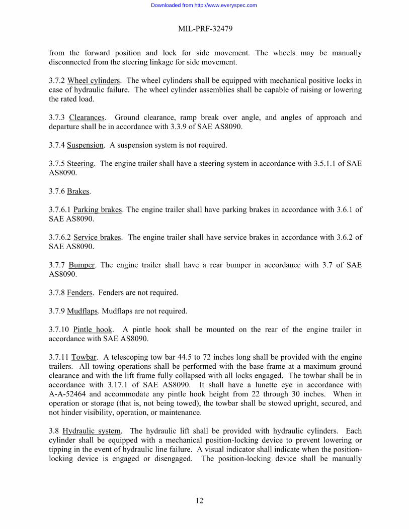
from the forward position and lock for side movement. The wheels may be manually disconnected from the steering linkage for side movement. 3.7.2 Wheel cylinders. The wheel cylinders shall be equipped with mechanical positive locks in case of hydraulic failure. The wheel cylinder assemblies shall be capable of raising or lowering the rated load. 3.7.3 Clearances. Ground clearance, ramp break over angle, and angles of approach and departure shall be in accordance with 3.3.9 of SAE AS8090. 3.7.4 Suspension. A suspension system is not required. 3.7.5 Steering. The engine trailer shall have a steering system in accordance with 3.5.1.1 of SAE AS8090. 3.7.6 Brakes. 3.7.6.1 Parking brakes. The engine trailer shall have parking brakes in accordance with 3.6.1 of SAE AS8090. 3.7.6.2 Service brakes. The engine trailer shall have service brakes in accordance with 3.6.2 of SAE AS8090. 3.7.7 Bumper. The engine trailer shall have a rear bumper in accordance with 3.7 of SAE AS8090. 3.7.8 Fenders. Fenders are not required. 3.7.9 Mudflaps. Mudflaps are not required. 3.7.10 Pintle hook. A pintle hook shall be mounted on the rear of the engine trailer in accordance with SAE AS8090. 3.7.11 Towbar. A telescoping tow bar 44.5 to 72 inches long shall be provided with the engine trailers. All towing operations shall be performed with the base frame at a maximum ground clearance and with the lift frame fully collapsed with all locks engaged. The towbar shall be in accordance with 3.17.1 of SAE AS8090. It shall have a lunette eye in accordance with A-A-52464 and accommodate any pintle hook height from 22 through 30 inches. When in operation or storage (that is, not being towed), the towbar shall be stowed upright, secured, and not hinder visibility, operation, or maintenance. 3.8 Hydraulic system. The hydraulic lift shall be provided with hydraulic cylinders. Each cylinder shall be equipped with a mechanical position-locking device to prevent lowering or tipping in the event of hydraulic line failure. A visual indicator shall indicate when the position-locking device is engaged or disengaged. The position-locking device shall be manually
Downloaded from http://www.everyspec.com
MIL-PRF-32479
13
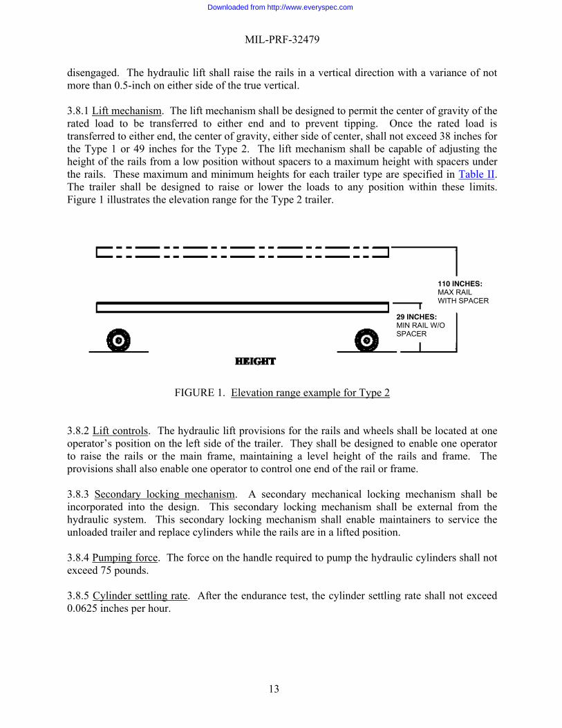
disengaged. The hydraulic lift shall raise the rails in a vertical direction with a variance of not more than 0.5-inch on either side of the true vertical. 3.8.1 Lift mechanism. The lift mechanism shall be designed to permit the center of gravity of the rated load to be transferred to either end and to prevent tipping. Once the rated load is transferred to either end, the center of gravity, either side of center, shall not exceed 38 inches for the Type 1 or 49 inches for the Type 2. The lift mechanism shall be capable of adjusting the height of the rails from a low position without spacers to a maximum height with spacers under the rails. These maximum and minimum heights for each trailer type are specified in Table II. The trailer shall be designed to raise or lower the loads to any position within these limits. Figure 1 illustrates the elevation range for the Type 2 trailer.
FIGURE 1. Elevation range example for Type 2
3.8.2 Lift controls. The hydraulic lift provisions for the rails and wheels shall be located at one operator’s position on the left side of the trailer. They shall be designed to enable one operator to raise the rails or the main frame, maintaining a level height of the rails and frame. The provisions shall also enable one operator to control one end of the rail or frame. 3.8.3 Secondary locking mechanism. A secondary mechanical locking mechanism shall be incorporated into the design. This secondary locking mechanism shall be external from the hydraulic system. This secondary locking mechanism shall enable maintainers to service the unloaded trailer and replace cylinders while the rails are in a lifted position. 3.8.4 Pumping force. The force on the handle required to pump the hydraulic cylinders shall not exceed 75 pounds. 3.8.5 Cylinder settling rate. After the endurance test, the cylinder settling rate shall not exceed 0.0625 inches per hour.
110 INCHES: MAX RAIL WITH SPACER
29 INCHES: MIN RAIL W/O SPACER
Downloaded from http://www.everyspec.com

MIL-PRF-32479
14
3.9 Rails. Each trailer type shall have parallel rails with a rail length as specified in Table II. The rail gage shall be 48 ± 0.12 inches along the entire length of the rail. The rail shall have a 3.33 ± 0.125 inch working face on each rail. The working face or flange of each rail shall have a minimum clearance of 0.90 inch on the inside and a minimum clearance of 0.55 inch on the outside. These clearances shall extend 3 inches below the face of the rail as specified in Figure 2. The end of each rail shall be square within +30, -0 minutes to ensure contact on the top of the rails. The ends of the parallel rails shall be in the same plane within 0.0625 inches. The top face of the rails shall be in the same plane within 0.0625 inches.
FIGURE 2. Rail clearances
Downloaded from http://www.everyspec.com

MIL-PRF-32479
15
3.9.1 Adjustments. The rails shall be joined together to obtain the following minimum adjustments as shown in Figure 3 through Figure 6 below at any height shown in Table II (with and without spacers) and with any load from no load and the proof load.
NOTES: 1. Yaw shall be 2.25º each direction from the centerline. 2. Roll shall be 10º each side of the horizontal centerline. 3. Lateral shall be 3 inches in each direction from the vertical centerline of the trailer. 4. Tilt shall be 10º from the horizontal at each end of the rails.
FIGURE 3. Yaw adjustment
2.25°
2.25°
Downloaded from http://www.everyspec.com

MIL-PRF-32479
16
FIGURE 4. Roll adjustment range
FIGURE 5. Lateral adjustment range
Downloaded from http://www.everyspec.com

MIL-PRF-32479
17
FIGURE 6. Tilt adjustment range
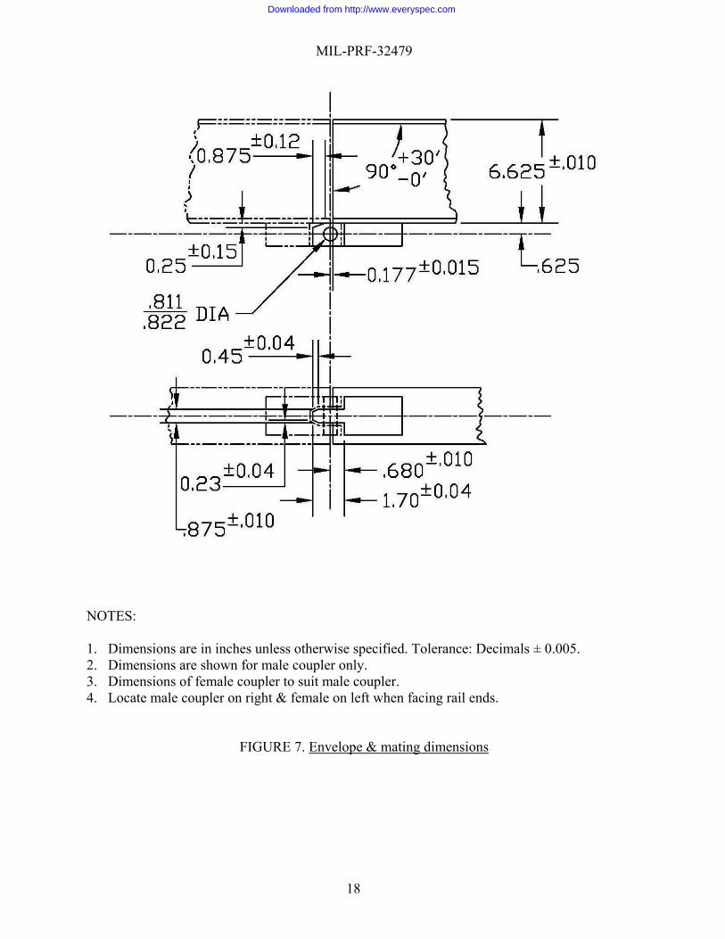
3.9.1.1 Control mechanisms. The mechanism for yaw, roll, and lateral adjustments shall be of the mechanical-type drive. The tilt adjustment shall be obtained by actuating the main hydraulic lift cylinders on each end of the trailer. The adjusting mechanisms shall be operable by hand while the respective size trailer is under its rated load as specified in Table II. The controls shall be located on the left side. A minimum clearance radius of 21.5 inches, with spacers installed (see 3.8.1), shall be provided between the rails and structure for mounting required components. 3.9.1.2 Spacers. Removable spacers shall be provided between the rails and lift structure. Removing the spacers shall permit the rails to be lowered 5.0 inches. 3.9.1.3 Control knobs. Control knobs shall have a 1/2-inch square drive for use with a 1/2-inch male wrench. 3.9.2 Overload. The trailer shall be so designed that the adjustments specified in 3.9.1 can be accomplished with standard 1/2-inch drive wrenches when each trailer is under its respective proof load as specified in Table II. While under its proof load, the trailer shall not tip or overturn when a 1,000 pound side load is applied at the side of the rails and the rails are raised to their maximum height with spacers installed (see 3.9.1.2). 3.9.3 Couplings. Each rail shall be equipped with a male and female coupling. The mating dimensions of the couplings shall be in accordance with Figure 7. The female coupling shall be provided with a quick-release, positive-lock-type pin. The pin shall be 3/4-inch in diameter, and permanently attached to the coupler by a steel cable. The pin shall have a double shear value in excess of 70,000 pounds.
Downloaded from http://www.everyspec.com
MIL-PRF-32479
18
NOTES: 1. Dimensions are in inches unless otherwise specified. Tolerance: Decimals ± 0.005. 2. Dimensions are shown for male coupler only. 3. Dimensions of female coupler to suit male coupler. 4. Locate male coupler on right & female on left when facing rail ends.
FIGURE 7. Envelope & mating dimensions
Downloaded from http://www.everyspec.com
MIL-PRF-32479
19
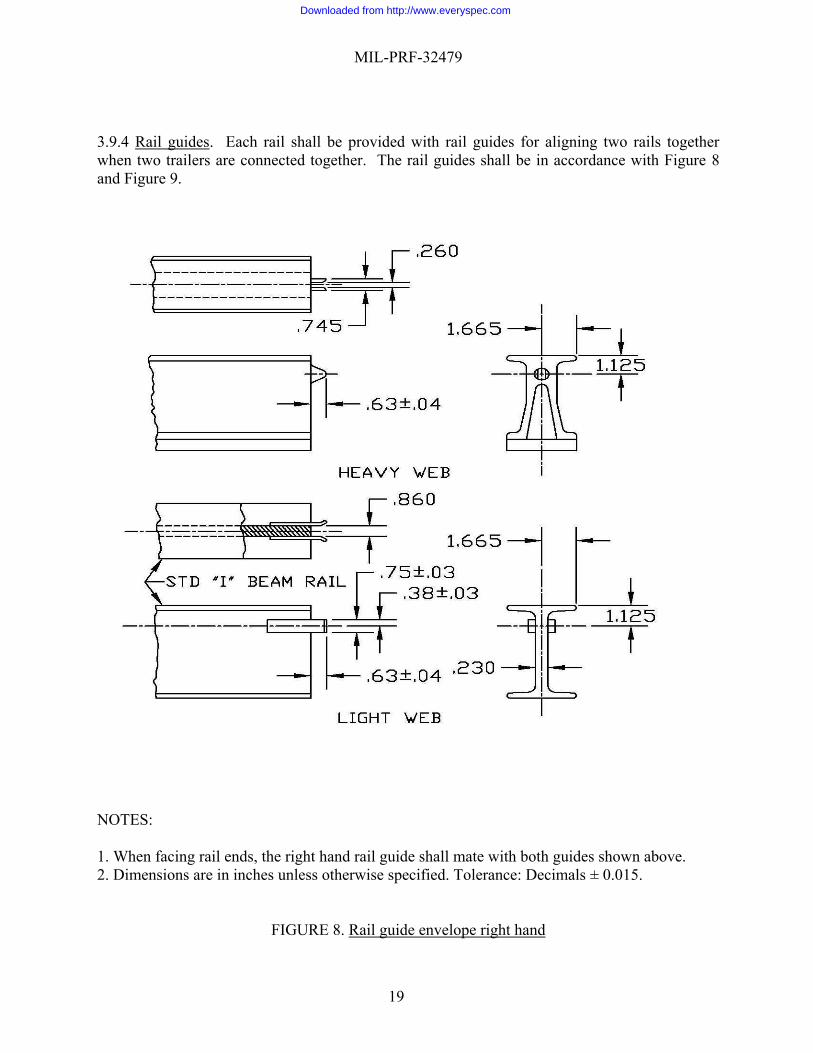
3.9.4 Rail guides. Each rail shall be provided with rail guides for aligning two rails together when two trailers are connected together. The rail guides shall be in accordance with Figure 8 and Figure 9.
NOTES: 1. When facing rail ends, the right hand rail guide shall mate with both guides shown above. 2. Dimensions are in inches unless otherwise specified. Tolerance: Decimals ± 0.015.
FIGURE 8. Rail guide envelope right hand
Downloaded from http://www.everyspec.com

MIL-PRF-32479
20
NOTES: 1. When facing rail ends, the left hand rail guide shall mate with both guides shown above. 2. Dimensions are in inches unless otherwise specified. Tolerance: Decimals: 0.015.
FIGURE 9. Rail guide envelope left hand
Downloaded from http://www.everyspec.com

MIL-PRF-32479
21
3.9.5 Rail stops. A positive, mechanical-type stop shall be provided near the extreme ends of each rail. In the event of failure to lock a roller adapter to the rails, the stops shall be designed to hold a component (weighing the rated load of Table II) from rolling off the rails. The stops shall be spring-loaded and manually retractable to permit a roller adapter to pass or roll along the rails to another trailer or into the aircraft. The rail stops shall be hand-operated and shall extend 0.5-inch above the face of the rails when fully extended. The rail stops shall engage the vertical face of the roller adapter. 3.10 Winch. A winch is not required. 3.11 Transportability. 3.11.1 Surface transportability. The engine trailers shall be transportable via all modes of surface shipment (highway, rail, and water) in accordance with MIL-STD-1366, and shall be capable of withstanding the mechanical shock and vibration characteristics of highway, rail, and water transport, except that design for rail impact testing (see 5.2.5 of MIL-STD-1366) is not required. 3.11.2 Air transportability. The trailers shall be transportable on C-130, C-17, and C-5 aircraft in accordance with MIL-STD-1791. In all air transport configurations, the trailers shall be capable of being restrained and withstanding, without loss of serviceability, 2.0 G up and 4.5 G down accelerations, and shall be capable of being restrained and withstanding, without loss of structural integrity, 3.0 G forward, 1.5 G aft, and 1.5 G lateral accelerations. The trailers shall be equipped with pressure relief devices or configured for air transport to prevent any part from becoming a projectile in the event of catastrophic loss of aircraft cabin pressure. The trailers shall roll on and off the aircraft, negotiating the required maximum ramp angles without shoring. 3.11.2.1 Shoring. The engine trailer shall be air transportable without shoring. 3.11.2.2 Tire pressure. Tire pressure shall not exceed 100 pounds per square inch (psi) and shall not be reduced for air transport. 3.11.2.3 Winch points. Winch points shall be provided at the front and rear of the engine trailer for aircraft loading using the aircraft’s winch. 3.11.2.4 Equipment removal and reconfiguration. Preparation for air transport shall take no more than 15 minutes and restoration to operating configuration shall take no more than 15 minutes for two persons using common hand tools (see 6.4.1). The only item that may be removed is the tow bar; if removed, it shall be stored on the engine trailer. 3.11.3 Tie downs. The trailers shall be symmetrically restrained during air and ground transport with tie down rings. Tie down points shall be rated at a minimum of 10,000 pounds, marked for capacity, with a clear opening compatible with the appropriate devices. Each end of each tie down device shall terminate at a tie down point and not pass through any other tie down point. There shall be no interference between tie down devices and the trailers.
Downloaded from http://www.everyspec.com

MIL-PRF-32479
22
3.11.4 Welders and welding. All welders shall be certified to weld in accordance with AWS D1.1 and AWS D1.2. The contractor shall make available to the Government certifications for all welders being utilized on the trailers. Welding procedures and all welding on the trailers shall be in accordance with AWS D1.1 and AWS D1.2. The surface parts to be welded shall be free from rust, scale, paint, grease, and other foreign matter. Welds shall be of sufficient size and shape to develop the full strength of the welded parts. Welds shall transmit stress without cracking or permanent distortion when the parts connected by the welds are subjected to test, proof, and service loadings. 3.12 Workmanship. The engine trailer including all parts and accessories, shall be constructed and finished in a thoroughly workmanlike manner. Workmanship objectives shall include freedom from blemishes, defects, burrs and sharp corners and edges; accuracy of dimensions, surface finish, and radii of fillets; thoroughness of welding, painting, and riveting; marking of parts and assemblies; and proper alignment of parts and tightness of assembly fasteners. 3.12.1 Bolted connections. Bolt holes shall be accurately punched or drilled and shall be deburred. Threaded fasteners shall be tight and shall not work loose during testing or service usage. 3.12.2 Riveted connections. Rivet holes shall be accurately punched or drilled and shall be deburred. Rivets shall be driven with pressure tools and shall completely fill the holes. Rivet heads shall be full, neatly made, concentric with the rivet holes and in full contact with the surface of the component. 3.12.3 Gear and lever assemblies. Gear and lever assemblies shall be properly aligned and meshed and shall be operable without interference, tight spots, loose spots, or other irregularities. Where required for accurate adjustment, gear assemblies shall be free of excessive backlash. 3.12.4 Cleaning. The engine trailer shall be thoroughly cleaned. Loose, spattered, or excess solder; welding slag; stray bolts, nuts, and washers; rust; metal particles; pipe compound; and other foreign matter shall be removed during and after final assembly. 4. VERIFICATION 4.1 Classification of inspections. The inspection requirements specified herein are classified as follows:
a. First article inspection (see 4.2). b. Conformance inspection (see 4.3)
Requirements shall be verified in accordance with Table III.
Downloaded from http://www.everyspec.com

MIL-PRF-32479
23
TABLE III. Requirement verification matrix
Section 3 Requirement Verification Method
Section 4 Verification
3.1 First article Not Applicable (N/A)
3.2 Engine trailer description. N/A 3.3 Design and construction. Examination 4.5.1 Examination of product. 3.3.1 Materials, protective coatings, and finish. N/A
3.3.1.1 Recycled, recovered, or environmentally preferable materials.
Examination 4.5.1 Examination of product.
3.3.1.2 Protective coatings. Examination 4.5.1 Examination of product. 3.3.1.2.1 Surface preparation and pretreatment. Examination 4.5.1 Examination of product.
3.3.1.2.2 Primer. Examination 4.5.1 Examination of product. 3.3.1.2.2.1 Ferrous surfaces. Examination 4.5.1 Examination of product. 3.3.1.2.2.2 Aluminum and mixed aluminum and ferrous surfaces. Examination 4.5.1 Examination of product.
3.3.1.2.3 Topcoat. Examination 4.5.1 Examination of product. 3.3.1.3 Dissimilar metals. Examination 4.5.1 Examination of product. 3.3.1.4 Finish. Examination 4.5.1 Examination of product. 3.3.1.5 Exclusion of water. Examination 4.5.1 Examination of product. 3.3.1.5.1 Fluid traps and faying surfaces. Examination 4.5.1 Examination of product.
3.3.1.5.2 Ventilation. Examination 4.5.1 Examination of product. 3.3.1.5.3 Drainage. Examination 4.5.1 Examination of product. 3.3.2 Markings. Examination 4.5.1 Examination of product. 3.3.3 Identification and information plates. N/A
3.3.3.1 Identification plate. Examination 4.5.1 Examination of product. 3.3.3.2 Transportation data plate. Examination 4.5.1 Examination of product. 3.3.5 Maintainability. Examination 4.5.1 Examination of product. 3.3.6 Operators. Examination 4.5.1 Examination of product. 3.3.7 Service life. Analysis 4.5.3 Service life analysis. 3.3.8 Safety. N/A 3.3.8.1 Environment, Safety, and Occupational Health (ESOH). N/A
3.3.8.1.1 System safety. Analysis 4.5.2 System safety hazard analysis.
3.3.8.1.2 Hazardous materials. Examination 4.5.1 Examination of product.
Downloaded from http://www.everyspec.com

MIL-PRF-32479
24
TABLE III. Requirement verification matrix - Continued
Section 3 Requirement
Verification Method
Section 4 Verification
3.3.8.2 Component protection. Examination 4.5.1 Examination of product.
3.3.8.3 Foolproofness. Examination 4.5.1 Examination of product. 3.3.8.4 Foreign object damage (FOD). Examination 4.5.1 Examination of product.
3.3.9 Human engineering. Examination 4.5.1 Examination of product. 3.3.10 Fastening devices. Examination 4.5.1 Examination of product. 3.4 Environmental conditions. N/A
3.4.1 Operating temperature range. Test
4.5.4.1 High temperature storage and operation test. 4.5.4.2 Low temperature storage and operation test.
3.4.2 Storage temperature range. Test
4.5.4.1 High temperature storage and operation test. 4.5.4.2 Low temperature storage and operation test.
3.4.3 Precipitation. N/A 3.4.3.1 Rain. Test 4.5.4.5 Rain test. 3.4.3.2 Snow. Analysis 4.5.4.6 Snow load analysis.
3.4.3.3 Ice. Test 4.5.4.7 Ice accretion test
3.4.4 Solar radiation. Examination 4.5.1 Examination of product. 3.4.5 Fungus. Examination 4.5.1 Examination of product. 3.4.6 Salt fog. Test 4.5.4.4 Salt fog test. 3.4.7 Sand and dust. Test 4.5.4.8 Sand and dust test. 3.4.8 Humidity Test 4.5.4.3 Humidity test
3.5 Weight, dimensions, and capacities. Test
4.5.5 Weight and dimension tests. 4.5.5.1 Weight and center of gravity test. 4.5.5.2 Dimension measurement.
3.6 Performance. N/A
3.6.1 Rated load. Test 4.5.7 Rated load test. Analysis 4.5.7.1 Structural analysis.
3.6.1.1 Tension load. Test 4.5.7.2 Tension load test. 3.6.2 Proof load. Test 4.5.7.3 Proof load test. 3.6.3 Endurance. Test 4.5.8 Endurance tests.
3.6.4 Mobility. Test 4.5.11 Mobility tests. 4.5.11.1 Towing test.
Downloaded from http://www.everyspec.com

MIL-PRF-32479
25
TABLE III. Requirement verification matrix - Continued
Section 3 Requirement
Verification Method
Section 4 Verification
3.6.4.1 Terrain. N/A
3.6.4.1.1 Paved surfaces. Test 4.5.11 Mobility tests. 4.5.11.1 Towing test.
3.6.4.1.2 Graded gravel. Test 4.5.11 Mobility tests. 4.5.11.1 Towing test.
3.6.4.1.3 Belgian block. Test 4.5.11 Mobility tests 4.5.11.1 Towing test..
3.6.4.2 Towing force. Test 4.5.11.1 Towing test. 3.6.4.3 Minimum curb-to-curb turning radius. Test 4.5.11.2 Turning radius test.
3.7 Chassis. Examination 4.5.1 Examination of product. 3.7.1 Tires and wheels. Examination 4.5.1 Examination of product. 3.7.2 Wheel cylinders. Test 4.5.12 Wheel cylinder tests. 3.7.3 Clearances. Test 4.5.5.2 Dimension measurement.
3.7.4 Suspension. Examination 4.5.1 Examination of product. Test 4.5.11 Mobility tests.
3.7.5 Steering. Examination 4.5.1 Examination of product. Test 4.5.11 Mobility tests.
3.7.6 Brakes. N/A 4.5.20 Brake tests. 3.7.6.1 Parking brakes. Test 4.5.20.1 Parking brake test. 3.7.6.2 Service brakes. Test 4.5.20.2 Service brake test. 3.7.7 Bumper. Examination 4.5.1 Examination of product. 3.7.8 Fenders. Examination 4.5.1 Examination of product. 3.7.9 Mudflaps. Examination 4.5.1 Examination of product. 3.7.10 Pintle hook. Examination 4.5.1 Examination of product. 3.7.11 Towbar. Examination 4.5.1 Examination of product. 3.8 Hydraulic system. Examination 4.5.1 Examination of product. 3.8.1 Lift mechanism. Examination 4.5.1 Examination of product. 3.8.2 Lift controls. Examination 4.5.1 Examination of product. 3.8.3 Secondary locking mechanism. Examination 4.5.1 Examination of product.
3.8.4 Pumping force. Test 4.5.9 Pumping force test. 3.8.5 Cylinder settling rate. Test 4.5.10 Cylinder settling rate test. 3.9 Rails. Examination 4.5.1 Examination of product. 3.9.1 Adjustments. Test 4.5.13 Adjustment controls. 3.9.1.1 Control mechanisms. Examination 4.5.1 Examination of product. 3.9.1.2 Spacers. Examination 4.5.1 Examination of product. 3.9.1.3 Control knobs. Examination 4.5.1 Examination of product.
Downloaded from http://www.everyspec.com
MIL-PRF-32479
26
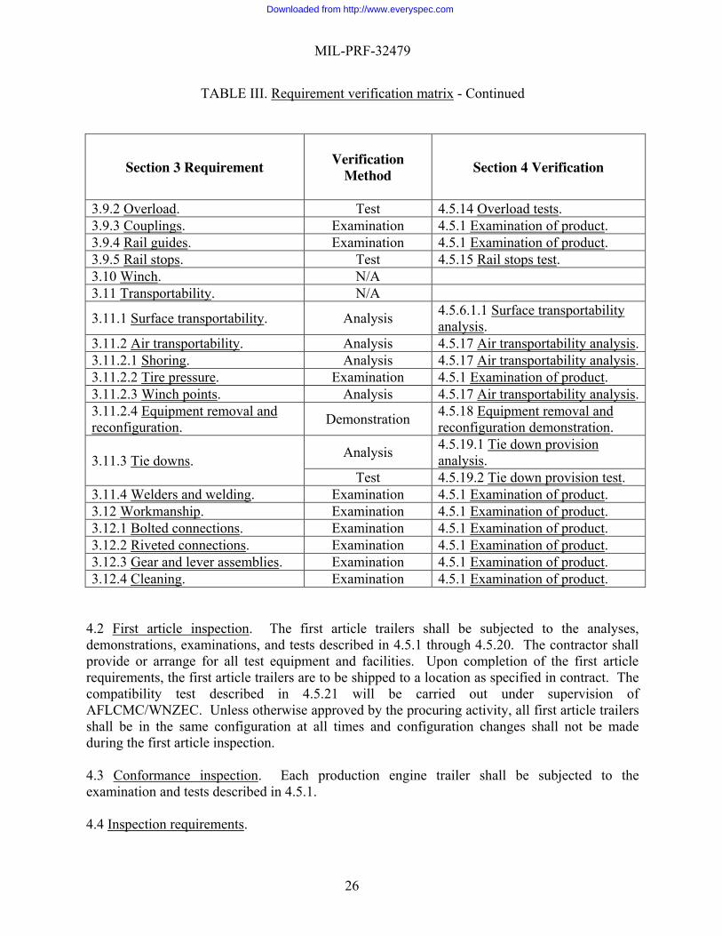
TABLE III. Requirement verification matrix - Continued
Section 3 Requirement
Verification Method
Section 4 Verification
3.9.2 Overload. Test 4.5.14 Overload tests. 3.9.3 Couplings. Examination 4.5.1 Examination of product. 3.9.4 Rail guides. Examination 4.5.1 Examination of product. 3.9.5 Rail stops. Test 4.5.15 Rail stops test. 3.10 Winch. N/A 3.11 Transportability. N/A
3.11.1 Surface transportability. Analysis 4.5.6.1.1 Surface transportability analysis.
3.11.2 Air transportability. Analysis 4.5.17 Air transportability analysis. 3.11.2.1 Shoring. Analysis 4.5.17 Air transportability analysis. 3.11.2.2 Tire pressure. Examination 4.5.1 Examination of product. 3.11.2.3 Winch points. Analysis 4.5.17 Air transportability analysis. 3.11.2.4 Equipment removal and reconfiguration. Demonstration 4.5.18 Equipment removal and
reconfiguration demonstration.
3.11.3 Tie downs. Analysis 4.5.19.1 Tie down provision analysis.
Test 4.5.19.2 Tie down provision test. 3.11.4 Welders and welding. Examination 4.5.1 Examination of product. 3.12 Workmanship. Examination 4.5.1 Examination of product. 3.12.1 Bolted connections. Examination 4.5.1 Examination of product. 3.12.2 Riveted connections. Examination 4.5.1 Examination of product. 3.12.3 Gear and lever assemblies. Examination 4.5.1 Examination of product. 3.12.4 Cleaning. Examination 4.5.1 Examination of product.
4.2 First article inspection. The first article trailers shall be subjected to the analyses, demonstrations, examinations, and tests described in 4.5.1 through 4.5.20. The contractor shall provide or arrange for all test equipment and facilities. Upon completion of the first article requirements, the first article trailers are to be shipped to a location as specified in contract. The compatibility test described in 4.5.21 will be carried out under supervision of AFLCMC/WNZEC. Unless otherwise approved by the procuring activity, all first article trailers shall be in the same configuration at all times and configuration changes shall not be made during the first article inspection. 4.3 Conformance inspection. Each production engine trailer shall be subjected to the examination and tests described in 4.5.1. 4.4 Inspection requirements.
Downloaded from http://www.everyspec.com

MIL-PRF-32479
27
4.4.1 General inspection requirements. Apparatus used in conjunction with the inspections specified herein shall be laboratory precision type, calibrated at proper intervals to ensure laboratory accuracy. 4.4.2 Data. During all testing specified herein, at least the following data, unless not applicable, shall be recorded at intervals not to exceed 30 minutes. Additional data and/or shorter intervals shall be provided as appropriate for any specific test.
a. Date. b. Time started. c. Time finished. d. Ambient temperature.
e. Ambient humidity.
4.4.3 Test rejection criteria. Throughout all tests specified herein, the engine trailers shall be closely observed for the following conditions, which shall be cause for rejection.
a. Failure to conform to design or performance requirements specified herein or in the contractor's technical proposal.
b. Any spillage or leakage of any liquid, including lubricant, or hydraulic fluid, under
any condition, except as allowed herein.
c. Structural failure of any component, including permanent deformation, or evidence of impending failure.
d. Evidence of excessive wear. If excessive wear is suspected, the original equipment
manufacturer’s (OEM’s) specifications or tolerances shall be utilized for making a determination.
e. Evidence of corrosion or deterioration.
f. Misalignment of components.
g. Conditions that present a safety hazard to personnel during operation, servicing, or
maintenance. h. Interference between the engine trailer components or between the engine trailers the
ground, and all required obstacles, with the exception of normal contact by the tires.
i. Evidence of undesirable mobility characteristics, including instability in handling during cornering, braking, and while traversing all required terrain.
Downloaded from http://www.everyspec.com

MIL-PRF-32479
28
4.4.4 Failure reporting, analysis, and corrective action system (FRACAS). A closed loop system shall be used to collect data, analyze, and record timely corrective action for all potential failures that occur during the first article. The contractor's existing FRACAS shall be utilized with the minimum changes necessary to conform to this specification. The system shall cover all test samples, interfaces between test samples, test instrumentation, test facilities, test procedures, test personnel, and the handling and operating instructions. The contractor shall establish and maintain a FRACAS database; all information shall be entered into the database. Authorized procuring activity personnel shall have read-only access to the FRACAS database. 4.4.4.1 Problem and failure action. At the occurrence of a problem or potential failure that affects satisfactory operation of a test sample, entries shall be made in the appropriate data logs and the failed test sample shall be removed from test, with minimum interruption to the other test samples continuing on test. 4.4.4.1.1 Problem and failure reporting. A failure report shall be initiated at the occurrence of each problem or potential failure of the contractor hardware. The report shall contain the information required to permit determination of the origin and correction of the failure. The contractor’s existing failure report form may be used with minimum changes necessary to conform to the requirements of this specification. The failure report form shall include the information specified in a through c:
a. Descriptions of failure symptoms, conditions surrounding the failure, failed hardware identification, and operating time (or cycles) at the time of failure.
b. Information on each independent and dependent failure and the extent of confirmation of
the failure symptoms, the identification of failure modes, and a description of all repair actions taken to return the test sample to operational readiness.
c. Information describing the results of the investigation, the analysis of all part failures, an
analysis of the system design, and the corrective action taken to prevent failure recurrence. If no corrective action is taken, the rationale for this decision shall be recorded.
4.4.4.1.2 Identification and control of failed items. A failure tag shall be affixed to the failed part immediately upon the detection of any failure or suspected failure. The failure tag shall provide space for the failure report serial number and for other pertinent entries from the test sample failure record. All failed parts shall be marked conspicuously or tagged and controlled to ensure disposal in accordance with contract requirements. Failed parts shall not be handled in any manner which may obliterate facts which might be pertinent to the analysis. Failed parts shall be stored pending disposition by the authorized approval agency of the failure analysis. 4.4.4.1.3 Problem and failure investigations. An investigation and analysis of each reported failure shall be performed. Investigation and analysis shall be conducted to the level of hardware or software necessary to identify causes, mechanisms, and potential effects of the failure. Any applicable method (for example, test, microscopic analysis, applications study, dissection, X-ray
Downloaded from http://www.everyspec.com

MIL-PRF-32479
29
analysis, spectrographic analysis) of investigation and analysis which may be needed to determine failure cause shall be used. When the removed part is not defective or the cause of failure is external to the part, the analysis shall be extended to include the circuit, higher hardware assembly, test procedures, and subsystem if necessary. This determination shall be documented for notification of the procuring activity. 4.4.4.1.4 Failure verification. Reported failures shall be verified as actual failures or an acceptable explanation provided to the procuring activity for lack of failure verification. Failure verification is determined either by repeating the failure mode of the reported part or by physical or electrical evidence of failure (for example, leakage residue or damaged hardware). Lack of failure verification, by itself, is not sufficient rationale to conclude the absence of a failure. 4.4.4.1.5 Corrective action. When the cause of failure has been determined, a corrective action shall be developed to eliminate or reduce the recurrence of the failure. Repairs shall be made in accordance with normal field operating procedures and manuals. The procuring activity shall review the corrective actions at the scheduled test status review prior to implementation. In all cases the failure analysis and the resulting corrective actions shall be documented. 4.4.4.1.6 Problem and failure tracking and closeout. The closed loop failure reporting system shall include provisions for tracking problems, failures, analyses, and corrective actions. Status of corrective actions for all problems and failures shall be reviewed at scheduled test status reviews. Problem and failure closeout shall be reviewed to assure their adequacy. 4.5 Test methods. 4.5.1 Examination of product. Each engine trailer shall be examined to verify compliance with the requirements herein prior to accomplishing any other demonstrations or tests listed in 4.5. A contractor-generated, Government-approved checklist (part of the test procedure) shall be used to identify each requirement not verified by an analysis, certification, demonstration, or test, and shall be used to document the examination results. Particular attention shall be given to materials, workmanship, dimensions, surface finishes, protective coatings and sealants and their application, welding, fastening, and markings. Proper operation of each engine trailer function shall be verified. Certifications and analyses shall be provided in accordance with Table IV. Each production engine trailer shall be inspected to a Government-approved reduced version of the checklist.
Downloaded from http://www.everyspec.com

MIL-PRF-32479
30
TABLE IV. Certifications and analyses.
Paragraph
Required Certifications and Analyses
3.3 Design and construction. Contractor documentation that the engine
trailer is in accordance with all applicable EU requirements in order to have the “CE” marking affixed.
3.3.7 Service life. Contractor analysis of the service life requirement (see 4.5.3).
3.3.8.1 System safety. Contractor system safety hazard analysis (see 4.5.2).
3.4.3.2 Snow. Contractor analysis of the snow load requirement (see 4.5.4.6)
3.4.4 Solar radiation. Contractor certification that the engine trailer performance is not adversely affected by full time exposure to solar radiation, such as those conditions encountered in desert environments.
3.4.5 Fungus. Contractor certifications that the materials used in construction of the engine trailer are fungus resistant or suitably treated to resist fungus.
3.11.1 Surface transportability. Contractor surface transportability analysis (see 4.5.6.1.1.) and certification that the engine trailer is transportable via all modes of surface shipment (highway, rail, and water) in accordance with MIL-STD-1366, and shall be capable of withstanding the mechanical shock and vibration characteristics of highway, rail, and water transport, except that design for rail impact testing (see 5.2.5 of MIL-STD-1366) is not required.
3.11.2 Air transportability. 3.11.2.1 Shoring. and 3.11.2.3 Winch points.
Contractor air transportability analysis (see 4.5.17).
3.11.3 Tie downs. Contractor tie down provision analysis (see 4.5.19.1).
3.11.4 Welders and welding. Contractor welder certifications. 4.5.2 System safety hazard analysis. A system safety hazard analysis of the engine trailer shall be conducted in accordance with 4.3.1 through 4.3.8 of MIL-STD-882 to demonstrate compliance with the mishap risk requirement of 3.3.8.1.1. 4.5.3 Service life analysis. An engineering analysis shall be performed to demonstrate compliance with the service life requirement of 3.3.7.
Downloaded from http://www.everyspec.com

MIL-PRF-32479
31
4.5.4 Environmental testing. 4.5.4.1 High temperature storage and operation test. A first article engine trailer of each type shall be tested in accordance with MIL-STD-810, Method 501.5, Procedures I and II, to demonstrate compliance with the high temperature storage and operating requirements of 3.4.1 and 3.4.2. Test duration shall be one 24-hour cycle for each procedure. At the end of the soaking period, the trailer shall be raised to its maximum height. The trailer shall then be tested in accordance with 4.5.7 and 4.5.9. Upon completion of high temperature testing the trailer shall be immediately road tested over improved roads for 5 miles at 20 mph and over unimproved roads for 5 miles at 5 mph. After the road test, the trailer shall be operated through all its operations under rated load. The lift mechanisms and the tilt, yaw, roll, and winch shall be operated through their full range. 4.5.4.2 Low temperature storage and operation test. A first article engine trailer of each type shall be tested in accordance with MIL-STD-810, Method 502.5, Procedures I and II, to demonstrate compliance with the low temperature storage and operating requirements of 3.4.1 and 3.4.2. Test duration shall be one 24-hour cycle for each procedure. At the end of the soaking period, the trailer shall be raised to its maximum height. The trailer shall then be tested in accordance with 4.5.7 and 4.5.9. Upon completion of low temperature testing the trailer shall be immediately road tested over improved roads for 5 miles at 20 mph and over unimproved roads for 5 miles at 5 mph. After the road test, the trailer shall be operated through all its operations under rated load. The lift mechanisms and the tilt, yaw, roll, and winch shall be operated through their full range. 4.5.4.3 Humidity test. A first article engine trailer of each type shall be tested in accordance with MIL-STD-810, Method 506.5, Procedure I, to demonstrate compliance with 3.4.8. The trailer shall then be tested in accordance with 4.5.7. Upon completion of humidity testing the trailer shall be immediately road tested over improved roads for 5 miles at 20 mph and over unimproved roads for 5 miles at 5 mph. After the road test, the trailer shall be operated through all its operations under rated load. The lift mechanisms and the tilt, yaw, roll, and winch shall be operated through their full range. 4.5.4.4 Salt fog test. A first article engine trailer of each type shall be tested in accordance with MIL-STD-810, Method 509.5, to demonstrate compliance with 3.4.6. Test duration shall be alternating 24-hour periods of salt fog exposure and drying conditions for 24-hour periods (two wet and two dry). The trailer shall then be tested in accordance with 4.5.7. Upon completion of salt spray testing the trailer shall be immediately road tested over improved roads for 5 miles at 20 mph and over unimproved roads for 5 miles at 5 mph. After the road test, the trailer shall be operated through all its operations under rated load. The lift mechanisms and the tilt, yaw, roll, and winch shall be operated through their full range. 4.5.4.5 Rain test. A first article engine trailer of each type shall be tested in accordance with MIL-STD-810, Method 506.5, Procedure I, to demonstrate compliance with 3.4.3.1.
Downloaded from http://www.everyspec.com

MIL-PRF-32479
32
4.5.4.6 Snow load analysis. An engineering analysis of each type shall be performed to demonstrate compliance with the snow load requirement of 3.4.3.2, using a specific gravity of snow of 0.1 (Ref. 5.3 of MIL-STD-810). 4.5.4.7 Ice accretion test. A first article engine trailer of each type shall be tested in accordance with MIL-STD-810, Method 521.3 with an ice thickness of 1.5-inches to demonstrate compliance with the ice accretion requirement of 3.4.3.3. The contractor shall identify those areas of the engine trailers where ice removal is required prior to operation. 4.5.4.8 Sand and dust test. A first article engine trailer of each type shall be tested in accordance with MIL-STD-810, Method 510.5, Procedures I (12 hours) and II (90 minutes per side), to demonstrate compliance with 3.4.7. 4.5.5 Weight and dimension tests. 4.5.5.1 Weight and center of gravity test. The weight of the first article engine trailers shall be measured to demonstrate compliance with the weight requirement of 3.5. The center of gravity shall be measured in accordance with 4.4 of TOP 2-2-800. 4.5.5.2 Dimension measurement. A first article engine trailers shall be measured to demonstrate compliance with the dimensional requirements of 3.5 and the clearance requirements of 3.7.3. 4.5.6 Transportability verification. 4.5.6.1 Surface transportability verification. 4.5.6.1.1 Surface transportability analysis. An engineering analysis shall be performed to demonstrate compliance with 3.6.1. The engineering analysis shall utilize the data for road transportation in accordance with MIL-STD-810, Method 514.6, Table 514.6C-II. 4.5.7 Rated load test. For each type trailer, its rated load shall be placed in the center of the rails support from two points on each rail and raised. The load shall then be shifted to each end of the trailer and the capability of the hydraulic cylinders shall be demonstrated. The load shall be applied in such a manner as to enable compression and tension loads to be applied to all lift cylinders. During this test, all controls shall be operated through their entire ranges. No binding or roughness of operation shall be evident. 4.5.7.1 Structural analysis. A structural analysis shall be performed to demonstrate compliance with the safety factor requirement of 3.6.1. 4.5.7.2 Tension load test. A first article engine trailer of each type shall be tested to demonstrate compliance with 3.6.1.1. 4.5.7.3 Proof load test. A first article engine trailer of each type shall be tested to demonstrate compliance with 3.6.2.
Downloaded from http://www.everyspec.com

MIL-PRF-32479
33
4.5.8 Endurance tests. An endurance test shall be conducted on the hydraulic system of a first article engine trailer of each type. The test shall consist of 50 cycles of raising its rated load as specified in Table II. One cycle shall consist of raising the trailer from collapsed height to the fully extended height and returning to the collapsed position. 4.5.9 Pumping force test. A first article engine trailer of each type shall be tested to demonstrate compliance with 3.8.4. 4.5.10 Cylinder settling rate test. A first article engine trailer of each type shall be tested to demonstrate compliance with 3.8.5. The settling rate shall be measured at 10, 50, and 90 percent of height adjustment. 4.5.11 Mobility tests. A first article engine trailer of each type shall be tested in accordance with Table VIII of SAE AS8090 to demonstrate compliance with the mobility requirements of 3.6.4. Note that the maximum towing force is 75 pounds per ton of gross weight, in accordance with 3.3.4 of SAE AS8090, rather than 50 pounds per ton of gross weight as stated in Table VIII of SAE AS8090. 4.5.11.1 Towing test. While carrying the rated load in low position, a first article engine trailer of each type shall be tested for type II mobility in accordance with SAE AS8090. The level paved highway distance may be performed for 200 miles, instead of the 600 miles defined for AS8090 Type II. Maximum test speed shall be 10.0 mph over paved surfaces, 10.0 mph over graded gravel, and 8.0 mph over Belgian block. The graded gravel road distance may be performed for 50 miles, instead of the 100 miles defined for AS8090 Type II. 4.5.11.2 Turning radius test. A first article engine trailer of each type shall be tested in both directions to demonstrate compliance with the turning radius requirement of 3.6.4.3. 4.5.12 Wheel cylinder tests. A first article engine trailer of each type shall be tested to demonstrate compliance with the wheel cylinder requirements of 3.7.2. 4.5.13 Adjustment controls. A first article engine trailer of each type shall be tested to demonstrate compliance with the adjustment requirements of 3.9.1. 4.5.14 Overload tests. A first article engine trailer of each type shall be tested to demonstrate compliance with 3.9.2. 4.5.15 Rail stops test. A first article engine trailer of each type shall be tested to demonstrate compliance with 3.9.5. 4.5.16 Winch test. Not applicable. 4.5.17 Air transportability analysis. An engineering analysis shall be performed to demonstrate compliance with the air transportability requirements of 3.11.2 and tie down requirements of 3.11.3. The analysis shall include the tie downs and all major components and their ability to withstand the accelerations specified in MIL-STD-1791. The evaluation shall also include a
Downloaded from http://www.everyspec.com

MIL-PRF-32479
34
dimensional analysis for each type trailer while traversing the ramp and while loaded aboard a C-130 aircraft. 4.5.18 Equipment removal and reconfiguration demonstration. A first article engine trailer of each type shall be configured for transport on aircraft and then reconfigured for operation to demonstrate compliance with 3.11.2.4. It shall be demonstrated that the forces required do not exceed those allowed in MIL-STD-1472. 4.5.19 Tie down provision verification. 4.5.19.1 Tie down provision analysis. An engineering analysis shall be performed on each type to demonstrate compliance with the tie down provision requirements of 3.11.3. 4.5.19.2 Tie down provision test. A first article engine trailer of each type shall be tested to demonstrate compliance with the tie down provision requirements of 3.11.3. 4.5.20 Brake tests. 4.5.20.1 Parking brake test. A first article engine trailer of each type shall be tested in accordance with 4.5.7.1 of SAE AS8090 to demonstrate compliance with 3.7.6.1. 4.5.20.2 Service brake test. A first article engine trailer of each type shall be tested in accordance with 4.5.7.2 and 4.5.8 of SAE AS8090 to demonstrate compliance with 3.7.6.2. 4.5.21 Compatibility test. A first article engine trailer of each type shall be fit tested to the aircraft and missile engines/adapter cradles for which they were designed to carry or a suitable substitute as deemed by the AFLCMC/WNZEC engineering authority. Upon completion of mounting the adapters and loading the engines on each engine trailer, the trailers shall be operated through all of its operations under rated load with the engines and adapters attached. The lift mechanisms and the tilt, yaw, roll, and winch shall be operated through their full range. Failure to properly mate the trailers with their respective engines/adapter cradles and complying with the required operations under load test shall be cause for rejection. 5. PACKAGING 5.1 Packaging. For acquisition purposes, the packaging requirements shall be as specified in the contract or order (see 6.2). When actual packaging of materiel is to be performed by DoD personnel, these personnel need to contact the responsible packaging activity to ascertain requisite packaging requirements. Packaging requirements are maintained by the Inventory Control Point's packaging activity within the Military Department or Defense Agency, or within the Military Department's System Command. Packaging data retrieval is available from the managing Military Department's or Defense Agency's automated packaging files, CD-ROM products, or by contacting the responsible packaging activity.
Downloaded from http://www.everyspec.com
MIL-PRF-32479
35
6. NOTES (This section contains information of a general or explanatory nature that may be helpful, but is not mandatory.) 6.1 Intended use. The ETU-8/E AND ETU-9/E Lift Trailers covered by this specification are intended for removal, transfer, and installation of aircraft engines and comparable heavy aircraft and missiles components. In addition, they are intended for use in some forms of field maintenance of aircraft engines. 6.2 Acquisition requirements. Acquisition documents should specify the following:
a. Title, number, and date of this specification.
b. Type of trailer required (see 1.2). c. If first article inspection is required (see 3.1). d. Packaging requirements (see 5.1).
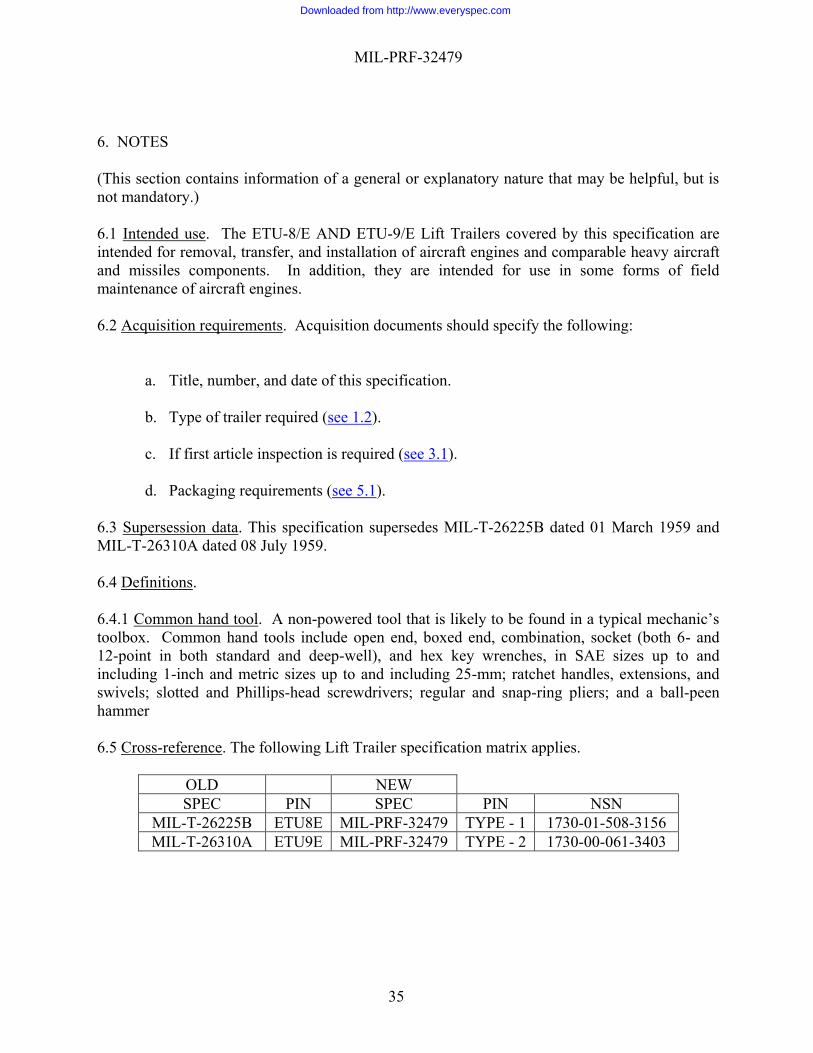
6.3 Supersession data. This specification supersedes MIL-T-26225B dated 01 March 1959 and MIL-T-26310A dated 08 July 1959. 6.4 Definitions. 6.4.1 Common hand tool. A non-powered tool that is likely to be found in a typical mechanic’s toolbox. Common hand tools include open end, boxed end, combination, socket (both 6- and 12-point in both standard and deep-well), and hex key wrenches, in SAE sizes up to and including 1-inch and metric sizes up to and including 25-mm; ratchet handles, extensions, and swivels; slotted and Phillips-head screwdrivers; regular and snap-ring pliers; and a ball-peen hammer 6.5 Cross-reference. The following Lift Trailer specification matrix applies.
OLD NEW SPEC PIN SPEC PIN NSN
MIL-T-26225B ETU8E MIL-PRF-32479 TYPE - 1 1730-01-508-3156 MIL-T-26310A ETU9E MIL-PRF-32479 TYPE - 2 1730-00-061-3403
Downloaded from http://www.everyspec.com

MIL-PRF-32479
36
6.6 Subject term (Key word) listing. Coupler Elevating lift Engine lift Hydraulic system Lift capacity Mobile transport Pintle hook Rails Towbar
NOTE: The activities listed above were interested in this document as of the date of this document. Since organizations and responsibilities can change, you should verify the currency of the information above using the ASSIST Online database at https://assist.dla.mil/ .
Custodians: Preparing Activity: Air Force - 84 Air Force – 84 (Project 1730-2014-001) Reviewers: Agent: Air Force - 11, 85, 99 Air Force – 99
Downloaded from http://www.everyspec.com