MIL-DTL-46100E (MR)
59
ADMINISTRATIVE NOTICE INCH-POUND MIL-DTL-46100E (MR) w/AMENDMENT 1 NOTICE 1 11 February 2009 DETAIL SPECIFICATION ARMOR PLATE, STEEL, WROUGHT, HIGH-HARDNESS The superseding information for MIL-DTL-46100E (MR) w/Amendment 1, dated 24 October 2008 is incorrect. It should read: SUPERSEDING, MIL-DTL-46100E (MR), dated 9 July 2008. Custodian: Preparing activity: Army - MR Army - MR Review activities: Army - AR, AT, TE DLA - IS NOTE: The activities listed above were interested in this document as of the date of this document. Since organizations and responsibilities can change, you should verify the currency of the information above using the ASSIST Online database at http://assist.daps.dla.mil . AMSC N/A FSC 9515 Source: http://www.assistdocs.com -- Downloaded: 2013-10-02T11:37Z Check the source to verify that this is the current version before use.
Transcript of MIL-DTL-46100E (MR)

ADMINISTRATIVE NOTICE
INCH-POUND
MIL-DTL-46100E (MR) w/AMENDMENT 1 NOTICE 1 11 February 2009
DETAIL SPECIFICATION
ARMOR PLATE, STEEL, WROUGHT, HIGH-HARDNESS The superseding information for MIL-DTL-46100E (MR) w/Amendment 1, dated 24 October 2008 is incorrect. It should read: SUPERSEDING, MIL-DTL-46100E (MR), dated 9 July 2008. Custodian: Preparing activity: Army - MR Army - MR Review activities: Army - AR, AT, TE DLA - IS NOTE: The activities listed above were interested in this document as of the date of this document. Since organizations and responsibilities can change, you should verify the currency of the information above using the ASSIST Online database at http://assist.daps.dla.mil. AMSC N/A FSC 9515
Source: http://www.assistdocs.com -- Downloaded: 2013-10-02T11:37ZCheck the source to verify that this is the current version before use.

INCH-POUND MIL-DTL-46100E (MR) w/AMENDMENT 1 24 October 2008
_
SUPERSEDING MIL-DTL-46100E (MR) 9 July 2006
DETAIL SPECIFICATION
ARMOR PLATE, STEEL, WROUGHT, HIGH-HARDNESS
This specification is approved for use by the Department of the Army and is available for use by all Departments and Agencies of the Department of Defense
1. SCOPE 1.1 Scope. This specification covers quenched and tempered high-hardness wrought steel armor plate for lightweight armor applications for ordered thicknesses from 0.118 inches (3 mm) up to an ordered thickness of 2.000 inches (50.8 mm), inclusive (see 6.1, 6.2, and 6.3). 1.2 Classification. Wrought armor should be of the following classes as specified in the contract or purchase order (see 6.2). If no class is specified then Class 1 should be supplied. 1.2.1 Class 1. Wrought armor plate which is liquid (e.g., water or oil) quenched and tempered. 1.2.2 Class 2. Wrought armor plate which is air quenched and tempered/autotempered.
Comments, suggestions, or questions on this document should be addressed to: Director, U.S. Army Research Laboratory, Weapons and Materials Research Directorate, Materials Applications Branch, Attn: AMSRD-ARL-WM-MC, Aberdeen Proving Ground, MD 21005-5069 or emailed to [email protected]. Since contact information can change, you may want to verify the currency of this address information using the ASSIST Online database at http://assist.daps.dla.mil/.
AMSC N/A FSC 9515 DISTRIBUTION STATEMENT A. Approved for public release; distribution is unlimited.
Source: http://www.assistdocs.com -- Downloaded: 2013-10-02T11:36ZCheck the source to verify that this is the current version before use.

MIL-DTL-46100E (MR) w/AMENDMENT 1
2. APPLICABLE DOCUMENTS 2.1 General. The documents listed in this section are specified in sections 3, 4, or 5 of this specification. This section does not include documents cited in other sections of this specification or recommended for additional information or as examples. While every effort has been made to ensure the completeness of this list, document users are cautioned that they must meet all specified requirements of documents cited in sections 3, 4, or 5 of this specification, whether or not they are listed. 2.2 Government documents. 2.2.1 Specifications, standards, and handbooks. The following specifications, standards, and handbooks form a part of this document to the extent specified herein. Unless otherwise specified, the issues of these documents are those cited in the solicitation or contract. DEPARTMENT OF DEFENSE STANDARDS
MIL-STD-129 - Military Marking for Shipment and Storage (Copies of these documents are available online at http://assist.daps.dla.mil/quicksearch/ or http://assist.daps.dla.mil/ or from the Standardization Document Order Desk, 700 Robbins Avenue, Building 4D, Philadelphia, PA 19111-5094.) 2.2.2 Other Government documents, drawings, and publications. The following other Government documents, drawings, and publications form a part of this document to the extent specified herein. Unless otherwise specified, the issues of these documents are those cited in the solicitation or contract. USADTC TOP 2-2-710 - Ballistic Tests of Armor Materials ITOP 2-2-713 - Ballistic Testing of Armor (Application for copies is available online at http://www.dtic.mil/ or from the Defense Technical Information Center, 8725 John J. Kingman Road, Suite 0944, Fort Belvoir, VA 22060-6218.) 2.3 Non-Government publications. The following documents form a part of this document to the extent specified herein. Unless otherwise specified, the issues of these documents are those cited in the solicitation or contract.
AMERICAN SOCIETY OF NONDESTRUCTIVE TESTING ANSI/ASNT CP-189-2006 - ASNT Standard for Qualification and Certification of Nondestructive Testing Personnel
2 Source: http://www.assistdocs.com -- Downloaded: 2013-10-02T11:36ZCheck the source to verify that this is the current version before use.

MIL-DTL-46100E (MR) w/AMENDMENT 1
(Copies of ANSI/ASNT publications are available from http:// www.asnt.org/shop/ or from the American Society for Nondestructive Testing, P.O. Box 28518, 1711 Arlingate Lane, Columbus, OH 43228-0518) ASTM INTERNATIONAL
ASTM A6/A6M - Standard Specification for General Requirements for Rolled Structural Steel Bars, Plates, Shapes and Sheet Piling ASTM A370 - Standard Test Methods and Definitions for
Mechanical Testing of Steel Products ASTM A578/ A578M - Standard Specification for Straight-Beam
Ultrasonic Examination of Rolled Steel Plates for Special Applications ASTM A751 - Standard Test Methods, Practices, and Terminology for Chemical Analysis of Steel Products
ASTM E10 - Standard Test Method for Brinell Hardness of Metallic Materials
ASTM E23 - Standard Test Methods for Notched Bar Impact Testing of Metallic Materials
ASTM E110 - Standard Test Method for Indentation Hardness of Metallic Materials by Portable Hardness Testers
ASTM E290 - Standard Test Methods for Bend Testing of Material for Ductility (DoD adopted) (Copies of these documents are available from www.astm.org or ASTM International, 100 Barr Harbor Drive, P.O. Box C700, West Conshohocken, PA 19428-2959.) 2.4 Order of precedence. Unless otherwise noted herein or in the contract, in the event of a conflict between the text of this document and the references cited herein (except for related specification sheets), the text of this document takes precedence. Nothing in this document, however, supersedes applicable laws and regulations unless a specific exemption has been obtained. 3. REQUIREMENTS 3.1 First article. When specified in the contract or purchase order (see 6.2, 6.4, and 6.9), a sample or samples of the specified item shall be made available to the contracting officer or his authorized representative for approval in accordance with 4.4. The contractor shall comply with this requirement at the time of his first order or contract and at any time that the supplier has not furnished the same class of high hard armor in the applicable thickness range (within the same nominal thickness ranges of Table V) under this specification within a period of 37 months. The approval of the first article samples authorizes the commencement of shipment but does not relieve the supplier of responsibility for compliance with all applicable provisions of this specification, namely conformance or
3 Source: http://www.assistdocs.com -- Downloaded: 2013-10-02T11:36ZCheck the source to verify that this is the current version before use.

MIL-DTL-46100E (MR) w/AMENDMENT 1
production acceptance. The first article samples and test plates shall be manufactured by the process proposed for use on production armor. The manufacturer's declared chemical analysis shall be submitted to the contracting agency (or purchasing activity) and to the ballistic test agency. The ballistic test agency shall record the first article ballistic test plates submitted, showing the dates tested. Requests from the procuring activity to the ballistic test agency as to prior conformance with first article tests shall be accompanied by copies of the first article test firing records. Any deviation(s) noticed by the ballistic agency shall be brought to the attention of the contracting activity and to the manufacturer. After first article testing has been accepted by the contracting activity, the composition and processing shall be considered fixed. If either of these change, outside the limitations allowed, then a new first article test shall be required. 3.1.1 First time producer. First time producers wishing to qualify to this specification shall follow the instructions of 6.7. 3.2 Production acceptance. 3.2.1 Chemical composition. A declared chemistry shall be submitted to the contracting agency or its authorized representative and to the ballistic test agency for each lot of material. The chemical composition of the declared chemistry shall conform to the requirements of Table I, column A, unless otherwise specified in the contract or purchase order (see 6.2). The chemical composition shall be determined by a product analysis (values shall be listed as weight percent) in accordance with 4.6.1.1 and 4.8.1. The first article samples and the production test plates shall utilize the same declared chemistry within the allowable ranges proposed for use in production. A statement showing the heat analysis of each melt and one product analysis of each lot and complete details of the heat treatment of each lot shall be furnished for the files of the purchaser at no cost. All elements of the chemical composition specified in Table I shall be shown in the statement. This statement shall be attached to the completed High Hard Armor Test Data Form (see Figure 1). 3.2.2 Carbon equivalence. Carbon equivalence (CE) shall be calculated for each heat per ASTM A6/A6M, i.e., CE = C + [Mn/6] + [(Cr + Mo + V)/5] + [(Ni + Cu)/15]
where the elements are expressed in wt%. 3.2.2.1 Class 1. Class 1 steels shall have a CE of less than 0.80 wt%. 3.2.2.2 Class 2. Class 2 steels shall have no CE limit unless otherwise specified in the contract or purchase order (see 6.2). 3.2.3 Heat treatment. All plates in each lot, including samples, shall receive the same heat treatment except for such variations in tempering temperature as shall be necessary to produce the prescribed hardness. Unless otherwise specified in the contract or purchase order (see 6.2), local or general heating shall not be performed after the final heat treating operation. This does not include preheating for welding or flame cutting, as long as the
4 Source: http://www.assistdocs.com -- Downloaded: 2013-10-02T11:36ZCheck the source to verify that this is the current version before use.

MIL-DTL-46100E (MR) w/AMENDMENT 1
tempering temperature is not exceeded (see 6.6 and 6.11). Tempering temperature shall be reported on Figure 1.
TABLE I. Chemical composition and precision (product analysis). 4/
ELEMENT
COLUMN A MAXIMUM LIMIT for
FIRST ARTICLE & PRODUCTION CHEMISTRY
(WEIGHT PERCENT)
COLUMN B 5/ ALLOWABLE RANGE
for FUTURE PRODUCTION LOTS (WEIGHT PERCENT)
Carbon 0.32 3/
Manganese
NONE REQUIRED, HOWEVER IF: < 1.00 > 1.00
± 0.15 ± 0.20
Phosphorus 0.020 1/ 3/ Sulfur 0.010 1/ 3/
Silicon
NONE REQUIRED, HOWEVER IF: < 0.60
> 0.60 to < 1.00 > 1.00
± 0.10 ± 0.15 ± 0.20
Nickel NONE REQUIRED 2/ ± 0.25
Chromium NONE REQUIRED, HOWEVER IF:
< 1.25 2/ > 1.25
± 0.15 ± 0.25
Molybdenum NONE REQUIRED, HOWEVER IF:
< 0.20 2/ > 0.20
± 0.035 ± 0.075
Vanadium NONE REQUIRED 2/ ± 0.075 Boron 0.003 3/ Copper 0.25 2/ 3/
Titanium 0.10 2/ 3/ Zirconium 0.10 2/ 3/ Aluminum 0.10 2/ 3/
Lead 0.01 2/ 3/ Tin 0.02 2/ 3/
Antimony 0.02 2/ 3/ Arsenic 0.02 2/ 3/
1/ Phosphorus and sulfur should be controlled to the lowest attainable levels, but in no case shall the combined phosphorus and sulfur contents exceed 0.025 wt%. 2/ When the amount of an element is less than 0.02 wt% the analysis may be reported as [ < 0.02 wt%]. 3/ Product analysis values may not exceed those listed as the maximum limit. 4/ Elements not listed in table, but intentionally added, shall be reported. 5/ Values are actual tolerance limits NOT percent tolerances. The analysis from the First Article sample is the “Declared Chemistry” which is used to calculate the range.
5 Source: http://www.assistdocs.com -- Downloaded: 2013-10-02T11:36ZCheck the source to verify that this is the current version before use.

MIL-DTL-46100E (MR) w/AMENDMENT 1
REQUEST FOR BALLISTIC TEST OF HIGH HARD ARMOR (MIL-DTL-46100) FIRING RECORD: DATE: REVISION: E AMENDMENT:1 Plate MANUFACTURER / PRODUCER: PRIME CONTRACTOR: Name: Name:
Address: Address:
POC: POC:
Phone No: Phone No:
Fax No: Fax No:
CONTRACT NO: ATC PROJECT NO:
DCAS REGION: BALLISTIC TEST CONTRACT NO:
TEST ITEM IDENTIFICATION: Lot No. ________ Plate No._______ CLASSIFICATION (CLASS):_________ Carbon Equivalence (CE):________ Ordered Thickness:_________
Bend Test:
Plate Thickness
Inside Radius
1)_________
1)_________
2)_________
2)_________
Pass / Fail
Pass / Fail
Tempering Temp (Class 1 only):________
Alloy and Temper:________________
Heat Treatment:__________________
PURPOSE: ___ Acceptance ___ First Article ___ Development SAMPLE: ___ Primary ___ Retest (See below)
Additional Requirements Specified in Contract: YES / NO (Firing Record No. of Failed Sample_________________)
Comments:
CHEMISTRY ANALYSIS C Mn P S Si Ni Cr Mo V
FIRST ARTICLE RESULTS:
PRODUCTION RESULTS:
ACCEPTANCE (Pass / Fail)
B: Cu: Ti: Zr: Al: Pb: Sn: Sb: As:
MECHANICAL PROPERTIES: CHARPY IMPACT @ -40 Degs. F. Specimen Size: _______________ HARDNESS:_________ LT Direction:1:_____ 2: ______3:_______ TL Direction:1:_ ____2: _ 3:_______
BALLISTIC TEST RESULTS: SEPARATELY HEAT TREATED TEST PLATE : YES_____NO_____
Obl.
(deg)
Actual
Thickness (in)
Required V50 (fps)
Actual V50 (fps)
Pass/
Fail
Test Projectile
Notes
LOTS REPRESENTED BY:
Reduced Testing Audit Testing
Lot [ met ] [failed to meet ] the ballistic requirements of specification MIL-DTL-46100.
Government Representative
Date Supplier Representative Date
FIGURE 1. High Hard Armor Test Data Form.
6 Source: http://www.assistdocs.com -- Downloaded: 2013-10-02T11:36ZCheck the source to verify that this is the current version before use.

MIL-DTL-46100E (MR) w/AMENDMENT 1
3.2.4 Condition. Unless otherwise specified in the contract or purchase order (see 6.2), plates shall be in the as-heat treated condition; surfaces shall not be pickled. 3.2.5 Mechanical properties. 3.2.5.1 Hardness. The surface hardness of each plate, including first article samples, shall be within the range of HBW 477 - HBW 534. The diameters of Brinell hardness impressions on any individual plate shall not vary by more than 0.15 mm (see 4.8.2). 3.2.5.2 Impact resistance. The minimum average Charpy V-notch impact resistance requirement of the armor plate shall be as shown in Table II. The Charpy V-notch specimens shall be obtained in both the TL orientation (i.e., transverse to the major direction of rolling with the notch perpendicular to the plate surface so that the crack shall propagate in the longitudinal direction) and the LT orientation (i.e., parallel to the major direction of rolling).
TABLE II. Minimum Charpy V-notch impact resistance requirements at -40°F ± 2°F.
SPECIMEN ORIENTATION
IMPACT RESISTANCE FOR STANDARD DEPTH SPECIMENS (ft. lbs.)
Standard width 3/4 width 1/2 width 1/4 width Transverse (T-L) 12.0 9.0 6.0 3.0
Longitudinal (L-T) 14.0 10.5 7.0 3.5 3.2.6 Bend test. All bend test samples from that lot shall be capable of being bent to the requirements specified in Table III without cracking as determined by visual inspection for thicknesses of 0.500 and under. When specified in the contract or purchase order (see 6.2), the bend test shall be performed on material thicker than 0.500 inch. Dimensions for thickness over 0.500 inches are listed in Table III for information purposes only. Two bend test samples shall be tested in the transverse direction per ASTM E290, transverse bend test, at room temperature through an included angle of 90° (unrestrained) to the inside radii shown below. After bending, samples shall be free of cracks as determined by visual inspection unless otherwise specified in the contract or order (see 6.2).
TABLE III. Bend test requirements.
PLATE THICKNESS (T) INSIDE RADIUS 0.118 to 0.3125 4T
Over 0.3125 to 0.500 6T
Over 0.500 to 0.750 8T Over 0.750 to 1.000 10T Over 1.000 to 2.000 12T
7 Source: http://www.assistdocs.com -- Downloaded: 2013-10-02T11:36ZCheck the source to verify that this is the current version before use.
MIL-DTL-46100E (MR) w/AMENDMENT 1
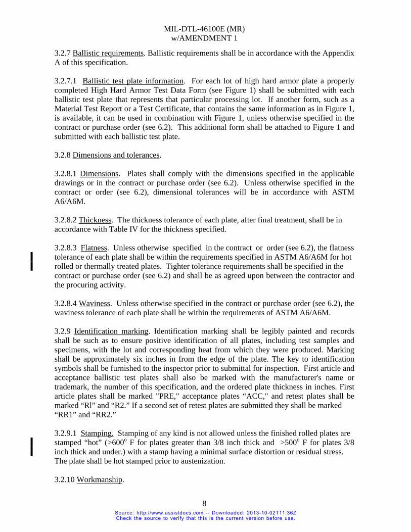
3.2.7 Ballistic requirements. Ballistic requirements shall be in accordance with the Appendix A of this specification. 3.2.7.1 Ballistic test plate information. For each lot of high hard armor plate a properly completed High Hard Armor Test Data Form (see Figure 1) shall be submitted with each ballistic test plate that represents that particular processing lot. If another form, such as a Material Test Report or a Test Certificate, that contains the same information as in Figure 1, is available, it can be used in combination with Figure 1, unless otherwise specified in the contract or purchase order (see 6.2). This additional form shall be attached to Figure 1 and submitted with each ballistic test plate. 3.2.8 Dimensions and tolerances. 3.2.8.1 Dimensions. Plates shall comply with the dimensions specified in the applicable drawings or in the contract or purchase order (see 6.2). Unless otherwise specified in the contract or order (see 6.2), dimensional tolerances will be in accordance with ASTM A6/A6M. 3.2.8.2 Thickness. The thickness tolerance of each plate, after final treatment, shall be in accordance with Table IV for the thickness specified. 3.2.8.3 Flatness. Unless otherwise specified in the contract or order (see 6.2), the flatness tolerance of each plate shall be within the requirements specified in ASTM A6/A6M for hot rolled or thermally treated plates. Tighter tolerance requirements shall be specified in the contract or purchase order (see 6.2) and shall be as agreed upon between the contractor and the procuring activity. 3.2.8.4 Waviness. Unless otherwise specified in the contract or purchase order (see 6.2), the waviness tolerance of each plate shall be within the requirements of ASTM A6/A6M. 3.2.9 Identification marking. Identification marking shall be legibly painted and records shall be such as to ensure positive identification of all plates, including test samples and specimens, with the lot and corresponding heat from which they were produced. Marking shall be approximately six inches in from the edge of the plate. The key to identification symbols shall be furnished to the inspector prior to submittal for inspection. First article and acceptance ballistic test plates shall also be marked with the manufacturer's name or trademark, the number of this specification, and the ordered plate thickness in inches. First article plates shall be marked "PRE," acceptance plates “ACC," and retest plates shall be marked “Rl” and “R2.” If a second set of retest plates are submitted they shall be marked “RR1” and “RR2.” 3.2.9.1 Stamping. Stamping of any kind is not allowed unless the finished rolled plates are stamped “hot” (>600o F for plates greater than 3/8 inch thick and >500o F for plates 3/8 inch thick and under.) with a stamp having a minimal surface distortion or residual stress. The plate shall be hot stamped prior to austenization. 3.2.10 Workmanship.
8 Source: http://www.assistdocs.com -- Downloaded: 2013-10-02T11:36ZCheck the source to verify that this is the current version before use.

MIL-DTL-46100E (MR) w/AMENDMENT 1
TABLE IV. Thickness tolerances for ordered thickness 1/, inches (over and under) 2/.
Tolerances over and under ordered thickness for widths given, inches
Specified Thickness,
inches
to 72 excl.
72 to 84 excl.
84 to 96 excl.
96 to 108 excl.
108 to 120 excl.
120 to 132 excl.
132 to 144 incl.
0.1180 0.016 0.016 0.019 0.019 0.023 --- --- 0.1250 0.016 0.016 0.019 0.019 0.023 --- --- 0.1875 0.016 0.016 0.019 0.019 0.023 --- --- 0.2500 0.016 0.016 0.019 0.019 0.023 --- --- 0.3125 0.016 0.019 0.019 0.019 0.023 0.026 --- 0.3750 0.016 0.019 0.019 0.023 0.023 0.026 --- 0.4375 0.016 0.019 0.019 0.023 0.026 0.026 0.031 0.5000 0.016 0.019 0.019 0.023 0.026 0.026 0.031 0.5625 0.019 0.019 0.019 0.023 0.026 0.031 0.031 0.6250 0.019 0.019 0.019 0.023 0.026 0.031 0.031 0.6875 0.019 0.019 0.019 0.023 0.026 0.031 0.031 0.7500 0.019 0.019 0.023 0.023 0.026 0.031 0.039 0.8125 0.023 0.023 0.023 0.026 0.031 0.031 0.039 0.8750 0.023 0.023 0.026 0.026 0.031 0.031 0.039 0.9375 0.023 0.023 0.026 0.026 0.031 0.036 0.043 1.0000 0.026 0.026 0.026 0.026 0.031 0.036 0.043 1.0625 0.026 0.026 0.026 0.031 0.031 0.036 0.043 1.1250 0.026 0.026 0.026 0.031 0.031 0.039 0.043 1.1875 0.031 0.031 0.031 0.031 0.036 0.043 0.048 1.2500 0.031 0.031 0.031 0.036 0.036 0.043 0.048 1.3125 0.031 0.031 0.031 0.036 0.036 0.043 0.053 1.3750 0.031 0.031 0.031 0.036 0.039 0.048 0.053 1.4375 0.036 0.036 0.036 0.036 0.043 0.048 0.058 1.5000 0.036 0.036 0.036 0.039 0.043 0.048 0.058 1.5625 0.036 0.036 0.036 0.039 0.043 0.058 0.058 1.6250 0.036 0.036 0.036 0.043 0.048 0.058 0.063 1.6875 0.039 0.039 0.039 0.043 0.048 0.058 0.063 1.7500 0.039 0.039 0.039 0.043 0.048 0.058 0.068 1.8125 0.043 0.043 0.043 0.048 0.053 0.058 0.068 1.8750 0.043 0.043 0.043 0.048 0.053 0.063 0.068 1.9375 0.043 0.043 0.043 0.048 0.053 0.063 0.076 2.0000 0.043 0.043 0.043 0.048 0.053 0.063 0.076
1/ For intermediate thickness, the tolerance of the closer specified gage shall apply. In case of mid-point, the tolerance for lower gage or interpolated value shall apply. 2/ When plates under 60 inches are rolled double width, the equivalent wider plate tolerance shall apply.
9 Source: http://www.assistdocs.com -- Downloaded: 2013-10-02T11:36ZCheck the source to verify that this is the current version before use.

MIL-DTL-46100E (MR) w/AMENDMENT 1
3.2.10.1 Surface condition. The top and bottom surface of each plate shall be free from the following surface defects: slivers, laps, checks, seams, blisters, snakes, cold shuts, cracks, burning, mechanical seams, mechanical gouges and laminations (see 6.10). The surface of each plate shall be such that mill scale or oxidation product shall not interfere with determination of acceptability. Imperfections listed above, which are of such a nature as to affect the fabrication of the materials, shall be rejected. 3.2.10.1.1 Depth of imperfections. The depth of rolled-in scale, scale pitting or snakes shall not exceed 0.015 inch and shall not reduce the steel thickness below the allowable minimum. Isolated individual pits over 0.015 inch deep but not over 0.03 inch deep and not within 6 inches of each other and which do not violate the minimum allowable thickness, as specified in the applicable drawings and fabrication documents, are acceptable. 3.2.10.2 Internal soundness. One plate from every lot that has an ordered thickness greater than 0.500 inch shall be ultrasonically examined for internal soundness in accordance with 4.8.6. The acceptance level shall be C, unless otherwise specified in the contract or purchase order (see 6.2). 3.2.10.3 Edge preparation and quality. 3.2.10.3.1 Plate. Thermal cutting of production plate shall be permitted after final heat treatment provided the procedure, which may include grinding after thermal cutting, is such that no cracks develop on any thermally cut edge whether detected by nondestructive inspection, or as agreed upon in the contract. The heat affected zone of thermally cut plates (up to and including 0.500 inches in thickness) shall not exceed 1.2 times the plate’s thickness from the cut edge. For plates over 0.500 inches thick, the heat affected zone shall not exceed 0.625 inches from the cut edge. Approval shall be obtained from the procuring activity and shall be as specified in the contract or purchase order (see 6.2) in order to have the heat affected zone exceed these limits. To reduce the potential for plate cracking, plates shall not be cut by cold shearing after final heat treatment, unless otherwise specified in the contract or purchase order (see 6.2). For plates that will be cut with a pattern of piece parts from within the edges of the plate, the condition of the discarded material shall not require inspection as long as cracks do not infringe into the pattern. 3.2.10.3.2 Piece parts cut from plate. For sections of production plate that are cut to size for a specific order from the vehicle fabricator, the supplier shall practice such necessary process controls to prevent edge cracking. For all piece parts, the supplier shall institute such necessary process inspection such that any cut edges shall comply with the requirements of 3.2.10.3.2.1.1 and 3.2.10.3.2.1.2 , using magnetic particle inspection, or liquid penetrant inspection. 3.2.10.3.2.1 Acceptance criteria. 3.2.10.3.2.1.1 Single linear indications. In any four inches of length a single linear indication shall not exceed twice the plate thickness.
10 Source: http://www.assistdocs.com -- Downloaded: 2013-10-02T11:36ZCheck the source to verify that this is the current version before use.

MIL-DTL-46100E (MR) w/AMENDMENT 1
3.2.10.3.2.1.2 Multiple linear indications. Multiple linear indications shall not exceed 1.5 times the plate thickness if two or more lie in the same plane. The total length of indications in one plane, in any four inch length, shall not exceed twice the plate thickness. No more than ten indications, whether in one plane or multiple planes, are permitted in any four inch length. 3.2.10.3.2.1.3 Removal of large indications. Rejectable indications shall be removed by the manufacturer or processor by grinding, provided the resulting cavity does not exceed 10 % of the ordered thickness. Weld repair is acceptable as long as it is done before the final heat treatment. 4. VERIFICATION 4.1 Classification of inspection. The inspection requirements specified herein are classified as follows: a. First article inspection (see 4.4). b. Production acceptance inspection (see 4.5). 4.2 Testing responsibility and facilities. Unless otherwise specified in the contract or purchase order (see 6.2), the contractor is responsible for the performance of all the requirements as specified herein. Unless otherwise specified in the contract or purchase order (see 6.2), the contractor may use his own or any other facilities suitable for the performance of the requirements specified herein, except ballistic tests (see 4.2.1), unless disapproved by the Government. The Government reserves the right to perform or check any of the inspections set forth in this specification where such inspections are deemed necessary to assure supplies and services conform to prescribed requirements and to determine the validity of the certifications. 4.2.1 Ballistic testing facility. Unless otherwise specified in the contract or purchase order (see 6.2), the ballistic test plates shall be forwarded to the Commander, USA ATC, ATTN: TEDT-AT-SLV, Building 358, 400 Colleran Road, APG, MD 21005-5059 or to an approved Government facility for ballistic testing (see 6.8) for first article or production acceptance. Alternate ballistic testing facilities shall be considered as indicated in 6.8. 4.3 Lot. A lot shall consist of all production and ballistic test plates of the same melt of steel, of the same ordered thickness, having the same treatment, and heat treated with the same thermal cycle in the same production furnace(s) in the same facility. When specified by the procuring activity (see 4.3.1 and 6.2), production and ballistic test plates shall be allowed to be heat treated separately. The test plate shall be heat treated in a production furnace. 4.3.1 Separately heat treated ballistic test plate. When the procuring activity allows a ballistic test plate to be heat treated separately from the production plates it represents (see 4.3), it shall be so stated in the data (see 6.6).
11 Source: http://www.assistdocs.com -- Downloaded: 2013-10-02T11:36ZCheck the source to verify that this is the current version before use.

MIL-DTL-46100E (MR) w/AMENDMENT 1
4.4 First article inspection. When required (see 6.2) first article inspection, except as otherwise indicated in this specification, shall utilize the same requirements and test methods as the production acceptance inspection shown in 4.5. 4.5 Production acceptance inspection. Production acceptance inspection shall include the examination of 4.7 and the tests of 4.8. 4.6 Sampling. 4.6.1 For first article inspection. 4.6.1.1 Chemical analysis samples. One sample for chemical analysis shall be taken from each plate submitted. 4.6.1.2 Impact samples. At least three (3) impact test specimens in each direction (TL & LT) shall be taken from each test plate submitted for ballistic testing. 4.6.1.3 Ballistic samples. Two (2) ballistic test plates of the same ordered thickness for each nominal thickness range shown in Table V shall be submitted for ballistic testing and shall represent any other thickness in the range. One sample shall be taken from the first plate heat treated and one from the last plate heat treated in the initial lot produced. When only one plate is heat treated, a sample shall be taken from each end of the plate. The ballistic test plates shall be 12 inches by 36 inches.
TABLE V. Thickness ranges and corresponding test projectiles for first article testing.
Nominal thickness range, in
Obliquity, degrees
Test Projectile Table
0.118 to 0.300 incl. 30 Cal .30 AP, M2 A-I 0.301 to 0.590 incl. 30 Cal .50 AP, M2 A-II 0.591 to 0.765 incl. 30 14.5 mm API, B32 A-III 0.766 to 1.130 incl. 30 14.5 mm API, BS41 A-IV 1.131 to 2.000 incl. 0 20 mm API-T, M602 A-V
4.6.1.4 Bend test samples. Unless otherwise specified in the contract or purchase order (see 6.2), two (2) samples shall be taken from each submitted test plate and shall be tested in accordance with 4.8.4 and shall meet the requirements of 3.2.6. 4.6.2 Sampling for production acceptance inspection. 4.6.2.1 For chemical analysis. At least one (1) sample for chemical analysis shall be taken from each heat in accordance with the applicable method specified in ASTM A751 (see 6.5). 4.6.2.2 For hardness tests. The Brinell hardness of each plate, as heat treated, shall be measured in two places, one at each end of a diagonal on one surface of the plate. Image
12 Source: http://www.assistdocs.com -- Downloaded: 2013-10-02T11:36ZCheck the source to verify that this is the current version before use.

MIL-DTL-46100E (MR) w/AMENDMENT 1
analysis systems may be used to read the indent and compute the hardness and if the heat treating process is continuous (not batch or oscillation), then the amount of testing may be reduced to one measurement per plate. For Class 2 materials, hardness tests shall be conducted in six places on each plate, one at each corner and roughly at both edges at the center of one surface of the plate. If consistent hardness readings are obtained with established process controls, hardness measurements may be reduced to 2 places on each diagonal corner. 4.6.2.3 For Charpy V-notch impact tests. A sample shall be taken from a plate representing each lot for Charpy V-notch impact tests. The sample shall be the same thickness as the plate it represents and large enough to obtain at least six specimens from the sample in accordance with 4.8.3. 4.6.2.4 For ballistic acceptance testing. One (1) plate, of each thickness to be supplied on the contract, shall be randomly taken from each lot for ballistic testing. In the event that plates of the same heat rolled to the same nominal thickness but with overlapping thickness tolerance ranges can be represented by one ballistic test plate, then only one of the ordered thicknesses need be submitted for acceptance testing. The other ordered thickness, however, shall be included on the applicable reporting form with the words indicating that it is represented by the sample to be tested. However, if the two ordered thicknesses are such that each thickness requires testing with a different type projectile as shown in Table IV, then each of the ordered thicknesses shall be ballistically tested. Unless otherwise specified in the contract or purchase order (see 6.2), the plates shall be 12 inches by 36 inches. Test projectiles shall be as specified in Table V. 4.6.2.5 Bend test samples. Unless otherwise specified in the contract or purchase order (see 6.2), two (2) samples shall be randomly taken from each lot for these tests representing the entire lot of material; however, when an entire heat represents only one lot the samples shall be taken from the first and last usable portion of the heat. Testing shall be conducted in accordance with 4.8.4 and shall meet the requirements of 3.2.6. 4.7 Examination. 4.7.1 Visual. All steel plate shall be subject to visual inspection for compliance with the requirements for identification marking (see 3.2.9) and for workmanship (see 3.2.10). 4.7.2 Dimensional. All steel plate shall be subject to inspection for compliance with dimensional and tolerance requirements (see 3.2.8). 4.7.3 Preparation for shipment. Examination shall be made to determine compliance with the requirements for preparation for shipment (see section 5). 4.8 Tests. 4.8.1 Chemical analysis. Chemical analysis shall be conducted in accordance with the applicable method specified in ASTM A751 (see 6.5). The analysis shall comply with the declared composition established in accordance with the requirements of Table I (see 3.2.1).
13 Source: http://www.assistdocs.com -- Downloaded: 2013-10-02T11:36ZCheck the source to verify that this is the current version before use.

MIL-DTL-46100E (MR) w/AMENDMENT 1
4.8.2 Hardness tests. Brinell hardness tests (HBW) shall be conducted in accordance with ASTM E10 or ASTM E110 (for portable testing), using a 10 mm carbide ball and a 3000 kilogram load. Surface scale and decarburization shall be removed from the areas where the tests are to be made. However, no more that 0.060 inches shall be removed from the test area. 4.8.2.1 Hardness tests for thin gage. For plates less than 0.187 inches (4.75 mm) in thickness, a Brinell hardness test shall be conducted in accordance with ASTM E10 or ASTM E110 (for portable testing), using either a 5 mm carbide ball and a 750 kilogram load or a 10 mm carbide ball and a 1500 kilogram load. 4.8.3 Charpy V-notch impact tests. At least three (3) Charpy V-notch impact test specimens per direction for a total of at least six (6) Charpy V-notch impact test specimens shall be taken from the sample and shall be prepared and tested in accordance with ASTM E23 and ASTM A370. Charpy V-notch impact test specimens shall be taken in both the TL orientation and in the LT orientation from locations midway between the top and bottom surfaces of the plate and at least 4 inches or 2T; whichever is less, from any quenched edge as well as outside the heat affected zone of any thermally-cut edge. The largest attainable subsize Charpy V-notch impact specimens shown in Figure 7 of ASTM E23 shall be used. 4.8.4 Bend test. The bend test shall be conducted in accordance with ASTM E290 using method referred to as the Guided-Bend Test, Figure 3. 4.8.5 Ballistic tests. Ballistic testing of armor plate shall be conducted at a Government approved test facility specified in 4.2.1, unless otherwise specified in the contract or purchase order (see 6.2). Testing shall be conducted in accordance with the requirements of Appendix A of this specification. 4.8.6 Ultrasonic examination. 4.8.6.1 Inspection equipment. The ultrasonic soundness inspection equipment shall conform to ASTM A578/A578M. 4.8.6.2 Procedure. Unless otherwise specified in the contract or purchase order (see 6.2), the ultrasonic examination shall be carried out in accordance with ASTM A578/A578M (see 3.2.10.2) with the following exceptions. (a) Scanning shall be continuous over 100% of the plate surface. (b) Scanning rate shall be at a speed where recordable discontinuities can be detected. (c) The testing frequency shall be a minimum of 2 megahertz (MHz). (d) Any area within a plate where a discontinuity produces a continuous total loss of back reflection accompanied by continuous indications on the same plane that cannot be encompassed within a circle whose diameter is 1 inch shall be cause for rejection of that plate. All discontinuities shall be evaluated using a frequency of 2 megahertz (MHz).
14 Source: http://www.assistdocs.com -- Downloaded: 2013-10-02T11:36ZCheck the source to verify that this is the current version before use.

MIL-DTL-46100E (MR) w/AMENDMENT 1
4.8.6.3 Certification of inspection personnel. Unless otherwise specified in the contract or purchase order (see 6.2), personnel performing ultrasonic inspection shall comply with the qualification requirements of ANSI/ASNT CP-189-2006. 4.9 Reduced testing. At the discretion of the procuring activity, the amount of testing shall be reduced provided the results on consecutive lots indicate that a satisfactory uniform product meeting the testing requirements is being produced and shall be specified in the contract or purchase order (see 6.2). Reduced testing shall be in accordance with a system previously approved or established by the procuring activity involved. 4.10 Rejection and retest for non-ballistic requirements. 4.10.1 Rejection. Unless otherwise specified in the contract or order (see 6.2), failure of the first article samples to meet the requirements of this specification shall be cause for rejection of the process, failure of the acceptance samples to meet the requirements of this specification shall be cause for rejection of the lot (see 4.10.2). For ballistic rejection procedures, see A.4.1.2. 4.10.2 Retest. Unless specific retest procedure is specified in the contract or order (see 6.2), two retest samples shall be submitted for each failed sample. Failure of either of the retest samples (plates) shall be cause for rejection of the material. First article retests shall not be permitted until the supplier has made the necessary corrections in the processing of the material to the satisfaction of the procuring activity. For ballistic retest procedures, see A.4.1.2. 5. PACKAGING 5.1 Packaging. For acquisition purposes, the packaging requirements shall be as specified in the contract or order (see 6.2). When packaging of materiel is to be performed by DoD or in-house contractor personnel, these personnel need to contact the responsible packaging activity to ascertain packaging requirements. Packaging requirements are maintained by the Inventory Control Point’s packaging activities within the Military Service or Defense Agency, or within the military service’s system command. Packaging data retrieval is available from the managing Military Department’s or Defense Agency’s automated packaging files, CD-ROM products, or by contacting the responsible packaging activity. 6. NOTES (This section contains information of a general or explanatory nature that may be helpful, but is not mandatory.) 6.1 Intended use. The steel armor covered by this specification is intended for lightweight applications where resistance to ball and armor piercing types of ammunition and multiple hit capabilities are required. 6.1.1 Class 1. Class 1 high hardness armor is intended for use in welded structures and appliqué.
15 Source: http://www.assistdocs.com -- Downloaded: 2013-10-02T11:36ZCheck the source to verify that this is the current version before use.

MIL-DTL-46100E (MR) w/AMENDMENT 1
6.1.2 Class 2. Class 2 high hardness armor is intended for use in welded structures and appliqué. However, its higher carbon equivalence (CE) may make it more difficult to weld than Class 1. 6.2 Acquisition requirements. Acquisition documents should specify the following:
a. Title, number and date of this specification. b. Specify ordered thickness (see 1.1) c. Specify class of steel (see 1.2).
d. If first article samples are required (see 3.1 and 4.4). e. If the declared chemistry composition can be different (see 3.2.1). f. Specify CE limit for Class 2 material, if required (see 3.2.2.2). g. If local or general heating can be performed after final heat treating (see 3.2.3). h. If plates may be furnished in a condition other than that specified (see 3.2.4). i. If a bend test is required for material greater than 0.500 inch in thickness (see
3.2.6). j. If another inspection for determining cracks is required (see 3.2.6 and 6.13). k. If a substitute form can not be used in place of Figure 1 (see 3.2.7.1). l. Specify dimensions (see 3.2.8.1). m. If dimensional tolerances can be other than in accordance with ASTM A6/A6M
(see 3.2.8.1). n. If the flatness tolerance is different than those specified (see 3.2.8.3). o. If tighter flatness tolerance requirements are to be specified (see 3.2.8.3). p. If the waviness tolerance is different than those specified (see 3.2.8.4). q. Specify the acceptance level for internal soundness if other than Level C as
defined in ASTM A578/A578M (see 3.2.10.2) r. If the limits specified for heat affected zone can to be exceeded (see 3.2.10.3.1). s. If plates can be cut by cold shearing after final heat treatment (see 3.2.10.3.1).
t. If someone other than the contractor is responsible for the performance of all the requirements of the specification (see 4.2).
u. If the contractor can’t use his own facility or any other facility for testing (see 4.2).
v. If the ballistic tests are to be conducted at another location (see 4.2.1 and 4.8.5). w. If production and ballistic test plates can be heat treated separately (see 4.3). x. If the number of bend test samples is different (see 4.6.1.4). y. If the size of the ballistic test plates can be different (see 4.6.2.4). z. If the bend test samples are selected other than randomly (see 4.6.2.5). aa. If the ultrasonic test procedures are different than that specified (see 4.8.6.2). ab. If a different certification for inspection personnel is required (see 4.8.6.3). ac. Specify reduced testing plan when applicable (see 4.9). ad. If rejection requirements differ (see 4.10.1). ae. If retest requirements differ (see 4.10.2). af. Preparation for delivery requirements (see section 5).
6.3 Fabrication. The armor plate covered by this specification is subject to fabrication involving cutting, drilling, forming, and welding. It is intended that selection and control of chemical composition, cleanliness, and plate processing will be such that the armor will be
16 Source: http://www.assistdocs.com -- Downloaded: 2013-10-02T11:36ZCheck the source to verify that this is the current version before use.

MIL-DTL-46100E (MR) w/AMENDMENT 1
suitable for fabrication in accordance with TACOM code 12479550, TACOM Ground Combat Vehicle Welding Code-Steel. Copies of this document are available from U.S. Army Tank-Automotive and Armaments Command, Warren, MI 48397-6000. The long dimension of the plate is normally the rolling direction. If a forming operation is to be performed, the rolling direction should be tracked so that bending is preferably not performed longitudinal to the rolling direction. 6.4 Special first article ballistic test. Special first article ballistic tests are required when the manufacturer changes either the heat treatment or the declared chemistry of the armor. 6.5 Chemical analysis. Suggested ASTM instrumental methods that can be used for chemical analysis are E322 and E415. ASTM A751 should be consulted for a complete list of methods. 6.6 Production plates. Material made to this specification has tendency to develop stress cracks if not tempered as soon as possible after austenitizing treatment. To avoid this situation, all plates should be left in the hot rolled or tempered condition while waiting for the ballistic test results. 6.7 Potential suppliers. Potential suppliers who have not previously supplied armor plate to MIL-DTL-46100 and wish to have their material ballistic tested, may do so at their own expense. It is recommended that inquiries for such testing be directed to Commander, USA ATC, ATTN: TEDT-AT-SLV, Building 358, 400 Colleran Road, APG, MD 21005-5059. 6.8 Alternate ballistic testing facility. Request for approval for an alternate ballistic testing facility should be forwarded by the procuring activity to the Director, U.S. Army Research Laboratory, Weapons and Materials Research Directorate, Specifications and Standards Office, Attn: AMSRD-ARL-WM-MC, Aberdeen Proving Ground, MD 21005-5069 and should be obtained prior to the contract award. 6.9 New contracts sponsored by government agencies. At the time that a new contract is initiated for the production of combat vehicles, the contractor's supplier is to estimate the number, size and delivery schedule of the ballistic test plates which are to be submitted for first article or acceptance testing (see 6.2). A lead time of 60 days after the contract has been signed is to be allowed prior to shipment of the first ballistic test(s) to APG to insure that all administrative functions for the establishment of a new ATC project have been completed in preparation for the test. The contracting government activity is to initiate the new project through a letter to Commander, USA ATC, ATTN: TEDT-AT-SLV, Building 358, 400 Colleran Road, APG, MD 21005-5059 requesting a cost estimate for the ballistic testing of the applicable number and sizes of plates. In the case of increases in scope of existing projects, similar correspondence is needed. 6.10 Definitions. 6.10.1 Slivers. An imperfection consisting of a very thin elongated piece of metal attached by only one end to the parent metal into whose surface it has been worked.
17 Source: http://www.assistdocs.com -- Downloaded: 2013-10-02T11:36ZCheck the source to verify that this is the current version before use.

MIL-DTL-46100E (MR) w/AMENDMENT 1
6.10.2 Laps. A surface imperfection with the appearance of a seam, caused by hot metal, fins or sharp corners being folded over and thus being forged or rolled into the surface but without being welded. 6.10.3 Checks. Checks are numerous very fine cracks at the surface of a metal part. Checks may appear during processing or during service and are most often associated with thermal cycling or thermal treatment. Also called check marks, checking, heat checks. 6.10.4 Seams. Seams are an unwelded fold or lap that appears as a crack, usually resulting from a discontinuity on a metal surface. 6.10.5 Blisters. A raised area, often dome shaped, resulting from delamination under pressure of expanding gas trapped in metal in a near sub-surface zone. Very small blisters may be called pinhead blisters or pepper blisters. 6.10.6 Snakes. Any crooked surface imperfection in a metal plate, resembling a snake. 6.10.7 Cold shuts. A lap on the surface of a forging or billet that was closed without fusion during deformation. 6.10.8 Burning. Permanently damaged metal due to overheating enough to cause incipient melting or intergranular oxidation. Note: This condition is usually obscured by normal cleaning methods and would require deep pickling and/or metallography to note the continuous oxidation (chicken wire effect) of the enlarged grain boundaries. This defect is usually not limited to the surface and may be sub-surface or at interior locations when associated with heavy mechanical working. Metal with this condition will be scrapped. 6.10.9 Laminations. A type of discontinuity with separation or weakness generally aligned parallel to direction of the worked surface of the metal and may be the result of pipe blisters, seams, inclusions, or segregation elongated and made directional by working. 6.10.10 Linear indication. For nondestructive examination purposes, a linear indication is evidence of a discontinuity that requires interpretation to determine its significance. 6.10.11 Autotempering. When the martensite start temperature (MS) lies well above room temperature, carbide precipitation (tempering) occurs upon quenching, after the transformation to martensite. Also called quench tempering. 6.11 Tempering. Any tempering should be performed as soon as possible after quenching. It is recommended that the delay after quenching be no greater than 24 hours. 6.12 Plates in the as-rolled condition. When the fabricator performs the final quench and temper of plates, it will be his responsibility that the mechanical and ballistic requirements of the plates, meet this specification. 6.13 Bend test inspection tests. If additional tests are required in the contract or purchase order, the following could be specified: “After bending, samples should be free of cracks as
18 Source: http://www.assistdocs.com -- Downloaded: 2013-10-02T11:36ZCheck the source to verify that this is the current version before use.

MIL-DTL-46100E (MR) w/AMENDMENT 1
19
determined by either penetrate inspection per ASTM E1417 or magnetic particle inspection per ASTM E1444 (see 3.2.6).” 6.14 Metric units. When metric dimensions are required, units for inch, foot, foot-pounds and feet per second may be converted to the metric equivalent by multiplying them by the following conversion factors listed in Table VI.
TABLE VI. Conversion factors.
English Multiply by Equals Metric SI unit inch 0.0254 = meter (m) foot 0.3048 = meter (m) pound 0.4536 = kilogram (kg) foot-lb 1.3558 = joule (j) feet/sec 0.3048 = meter per second (m/s)
Note: Conversion factors can be associated with ASTM E380 entitled “Metric Practice Guide.” 6.15 Subject term (key word) listing.
Ballistic testing Batch tempering Continuous tempering Lightweight armor Heat treated plates
6.16 Changes from previous issue. The margins of this standard are marked with vertical lines to indicate modifications generated by this change. This was done as a convenience only and the Government assumes no liability whatsoever for any inaccuracies in these notations. Bidders and contractors are cautioned to evaluate the requirements of this document based on the entire content irrespective of the marginal notations.
Source: http://www.assistdocs.com -- Downloaded: 2013-10-02T11:36ZCheck the source to verify that this is the current version before use.

MIL-DTL-46100E (MR) w/AMENDMENT 1
APPENDIX A
BALLISTIC TESTING OF ARMOR PLATE, STEEL, WROUGHT HIGH HARDNESS
A.1 SCOPE A.1.1 This appendix covers the requirements for ballistic testing of high hardness steel armor plate. A.2 DEFINITIONS A.2.1 Fair impact. A fair impact is an impact resulting from the striking of the test plate by a projectile in normal flight (no yawing or tumbling) and separated from another impact or the edge of the plate, hole, crack, or spalled area by an undisturbed area of at least two test projectile diameters. A.2.2 Witness sheet. A witness sheet is normally a 0.014 inch thick sheet of 5052 H36 aluminum alloy (or a 0.020 inch thick sheet of 2024 -T3 aluminum alloy) placed 6 inches (+ 0.5 inch) behind and parallel to the test plate or other ballistic sample. A.2.3 Complete penetration, protection, CP(P). A protection complete penetration is a penetration in which the projectile or one or more fragments of the projectile or plate pass beyond the back of the test plate and perforates the witness plate. A.2.4 Partial penetration, protection, PP(P). A partial penetration is any impact that is not a complete penetration. A.2.5 Gap. The difference in velocity between the high partial penetration velocity and the low complete penetration velocity used in computing the ballistic limit where the high partial penetration velocity is lower than the low complete penetration velocity. A.2.6 V50 protection ballistic limit, BL(P). The protection V50 ballistic limit is defined as the average of 6 fair impact velocities comprising the three lowest velocities resulting in complete penetration and the three highest velocities resulting in partial penetration. A maximum spread of 150 feet per second (fps) shall be permitted between the lowest and highest velocities employed in determination of ballistic limits. In only those cases where the lowest complete penetration velocity is lower than the highest partial penetration velocity by more than 150 fps shall the ballistic limit be based on 10 velocities (the 5 lowest velocities that resulted in complete penetration and the 5 highest velocities that resulted in partial penetrations). When the 10-round excessive spread, ballistic limit is used, the velocity spread shall be reduced to the lowest practical level (as close to 150 fps as possible). When a 10-round ballistic limit is used, this shall be noted in all reports. The normal up-and-down firing method shall be used in the determination of all BL(P)'s, all velocities being corrected to striking velocity. In the event that the ballistic limit computed is less than 30 fps above the minimum required and if a gap (high partial penetration velocity below the low complete penetration velocity) of 30 fps or more exists, firing shall
20 Source: http://www.assistdocs.com -- Downloaded: 2013-10-02T11:36ZCheck the source to verify that this is the current version before use.

MIL-DTL-46100E (MR) w/AMENDMENT 1
APPENDIX A
continue as needed to reduce this gap to 25 fps or less. (This procedure shall insure better evaluation of the steel when the ballistic limit is near the minimum required.) A.2.7 Thickness, impact area. The thickness of ballistic test plates used for determining ballistic limits shall be that of the area subjected to the ballistic testing. A.3 REQUIREMENTS A.3.1 Resistance to penetration. The minimum ballistic limits shall be in accordance with the values shown in Tables A-I, A-II, A-III, A-IV or A-V, as applicable. A.3.2 Resistance to cracking. Ballistic test plates when visually examined after testing shall not develop any through-crack greater in length than five calibers of the projectile. A.4 TESTS A.4.1 Ballistic tests. V50 ballistic tests shall be performed in accordance with USADTC TOP 2-2-710, Ballistic Tests of Armor Materials or ITOP 2-2-713, Ballistic Testing of Armor to determine compliance with the requirements of Tables A-I through A-V. A.4.1.1 Plate thickness. Plate thickness as measured by the ballistic test agency shall be used to determine the required ballistic limit for the plate. Individual thickness measurements are to be read from a micrometer to the nearest 0.001 inch and the average of these readings reported to the nearest 0.001 inch. At least one measurement shall be taken along each edge of the plate at a distance of at least one inch from the edge, but preferably in the area which shall be impacted. The average of the measurements to the nearest 0.001 inch shall be used to determine the minimum ballistic limit requirements in the appropriate tables (Tables A-I through A-V). The required ballistic limit shall be determined by interpolation, if necessary, in the Tables in the Appendix. A.4.1.2 Rejection and retest of ballistic plates. A.4.1.2.1 First article tests (rejection). Unless noted otherwise in the contract or order, failure of either of the first article test plates to meet the minimum ballistic requirements as specified in the Appendix to this specification indicates failure of the product and process. A.4.1.2.2 First article (retests). Resubmission of ballistic retest plates shall not be made until the manufacturer has made the necessary corrections in the processing of the material to the satisfaction of the procuring activity. Two retest plates must be submitted for first article testing and both must pass.
21 Source: http://www.assistdocs.com -- Downloaded: 2013-10-02T11:36ZCheck the source to verify that this is the current version before use.

MIL-DTL-46100E (MR) w/AMENDMENT 1
APPENDIX A
A.4.1.2.3 Acceptance tests (rejection). Unless otherwise noted in the contract or order, failure of a test plate to meet the ballistic requirements indicates failure of the lot, however, the final decision shall depend on the outcome of retests, if submitted. A.4.1.2.4 Acceptance tests (retests). If a test plate representing a lot fails to meet the ballistic requirements, the manufacturer has the following options. Immediately upon notification of the failure:
(1) At manufacturer’s expense submit two additional test plates from the same lot for ballistic retest, or
(2) First reheat treat (quenching and tempering) the lot and then submit a test plate from the retreated lot, or
(3) Scrap the lot and submit a plate representing a new lot for acceptance. If the manufacturer chooses any one of these options and the ballistic retest plate (or plates) meets the requirements, then the lot represented is acceptable. If option (1) is chosen and one or both of the retest plates fail, the manufacturer may reheat treat the lot and submit a test plate from the retreated lot. If this plate fails, the lot is rejected. If option (3) is chosen and the test plate fails, any one of the three options may be chosen again. The manufacturer shall report the processing used on the failed plates. A.4.1.3 Disposition of ballistic test plates. A.4.1.3.1 First article test plates. Upon request of the applicant within 15 days after ballistic testing, first article plates shall be returned "as is" to the applicant, at his expense, unless the plates were destroyed in testing. A.4.1.3.2 Acceptance test plates. Acceptance test plates that comply with the requirements of this specification are considered as part of the lot of steel they represent and ownership of them passes to the Government with the acceptance of that lot. Acceptance test plates that fail to comply with the requirements of this specification are considered as part of the lot they represent and remain the property of the producer just as the rejected lot does. The failed plates shall be returned, upon request, as in A.4.1.3.1.
22 Source: http://www.assistdocs.com -- Downloaded: 2013-10-02T11:36ZCheck the source to verify that this is the current version before use.

MIL-DTL-46100E (MR) w/AMENDMENT 1
APPENDIX A
TABLE A-I. Minimum required ballistic limits - caliber .30 AP M2 projectile at 30 degrees obliquity.
Thickness
inches Required
BL(P), ft/sec Thickness
inches Required
BL(P), ft/sec Thickness
inches Required
BL(P), ft/sec
0.100 616 0.180 1647 0.265 2329 0.105 694 0.185 1697 0.270 2359 0.110 770 0.190 1746 0.275 2389 0.115 845 0.195 1793 0.280 2418
0.118 1/ 889 0.200 1839 0.285 2447 0.120 917 0.205 1884 0.290 2474 0.125 988 0.210 1927 0.295 2501 0.130 1057 0.215 1969 0.300 2/ 2527 0.135 1123 0.220 2010 0.305 2553 0.140 1188 0.225 2050 0.310 2578 0.145 1251 0.230 2088 0.315 2603 0.150 1313 0.235 2126 0.320 2627 0.155 1373 0.240 2162 0.325 2650 0.160 1431 0.245 2197 0.330 2674 0.165 1487 0.250 2232 0.335 2697 0.170 1542 0.255 2265 0.340 2719 0.175 1595 0.260 2297
1/ Specification requirements begin for this ordered thickness. 2/ Specification requirements end for this ordered thickness.
Note: Tabulated values on either side of the ordered thicknesses are for interpolation of BL(P) requirements on undersize or oversize plates.
23 Source: http://www.assistdocs.com -- Downloaded: 2013-10-02T11:36ZCheck the source to verify that this is the current version before use.
MIL-DTL-46100E (MR) w/AMENDMENT 1
APPENDIX A
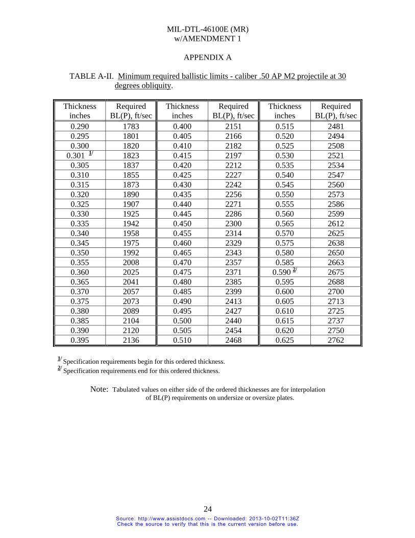
TABLE A-II. Minimum required ballistic limits - caliber .50 AP M2 projectile at 30
degrees obliquity.
Thickness inches
Required BL(P), ft/sec
Thickness inches
Required BL(P), ft/sec
Thickness inches
Required BL(P), ft/sec
0.290 1783 0.400 2151 0.515 2481 0.295 1801 0.405 2166 0.520 2494 0.300 1820 0.410 2182 0.525 2508
0.301 1/ 1823 0.415 2197 0.530 2521 0.305 1837 0.420 2212 0.535 2534 0.310 1855 0.425 2227 0.540 2547 0.315 1873 0.430 2242 0.545 2560 0.320 1890 0.435 2256 0.550 2573 0.325 1907 0.440 2271 0.555 2586 0.330 1925 0.445 2286 0.560 2599 0.335 1942 0.450 2300 0.565 2612 0.340 1958 0.455 2314 0.570 2625 0.345 1975 0.460 2329 0.575 2638 0.350 1992 0.465 2343 0.580 2650 0.355 2008 0.470 2357 0.585 2663 0.360 2025 0.475 2371 0.590 2/ 2675 0.365 2041 0.480 2385 0.595 2688 0.370 2057 0.485 2399 0.600 2700 0.375 2073 0.490 2413 0.605 2713 0.380 2089 0.495 2427 0.610 2725 0.385 2104 0.500 2440 0.615 2737 0.390 2120 0.505 2454 0.620 2750 0.395 2136 0.510 2468 0.625 2762
1/ Specification requirements begin for this ordered thickness. 2/ Specification requirements end for this ordered thickness.
Note: Tabulated values on either side of the ordered thicknesses are for interpolation of BL(P) requirements on undersize or oversize plates.
24 Source: http://www.assistdocs.com -- Downloaded: 2013-10-02T11:36ZCheck the source to verify that this is the current version before use.

MIL-DTL-46100E (MR) w/AMENDMENT 1
APPENDIX A
TABLE A-III. Minimum required ballistic limits – 14.5 mm API B32 projectile at 30
degrees obliquity.
Thickness inches
Required BL(P), ft/sec
Thickness inches
Required BL(P), ft/sec
Thickness inches
Required BL(P), ft/sec
0.575 2320 0.645 2469 0.720 2621 0.580 2331 0.650 2480 0.725 2630 0.585 2342 0.655 2490 0.730 2640 0.590 2353 0.660 2500 0.735 2650
0.591 1/ 2355 0.665 2511 0.740 2659 0.595 2364 0.670 2521 0.745 2669 0.600 2374 0.675 2531 0.750 2679 0.605 2385 0.680 2541 0.755 2688 0.610 2396 0.685 2551 0.760 2698 0.615 2407 0.690 2561 0.765 2/ 2707 0.620 2417 0.695 2571 0.770 2717 0.625 2428 0.700 2581 0.775 2726 0.630 2438 0.705 2591 0.780 2736 0.635 2449 0.710 2601 0.785 2745 0.640 2459 0.715 2611 0.790 2754
1/ Specification requirements begin for this ordered thickness. 2/ Specification requirements end for this ordered thickness.
Note: Tabulated values on either side of the ordered thicknesses are for interpolation of BL(P) requirements on undersize or oversize plates.
25 Source: http://www.assistdocs.com -- Downloaded: 2013-10-02T11:36ZCheck the source to verify that this is the current version before use.

MIL-DTL-46100E (MR) w/AMENDMENT 1
APPENDIX A
TABLE A-IV. Minimum required ballistic limits – 14.5 mm API BS41 projectile at 30
degrees obliquity.
Thickness inches
Required BL(P), ft/sec
Thickness inches
Required BL(P), ft/sec
Thickness inches
Required BL(P), ft/sec
0.740 2212 0.880 2564 1.025 2886 0.745 2225 0.885 2576 1.030 2896 0.750 2239 0.890 2588 1.035 2907 0.755 2252 0.895 2599 1.040 2917 0.760 2265 0.900 2611 1.045 2927 0.765 2278 0.905 2622 1.050 2938
0.766 1/ 2281 0.910 2634 1.055 2948 0.770 2292 0.915 2645 1.060 2958 0.775 2305 0.920 2657 1.065 2968 0.780 2318 0.925 2668 1.070 2979 0.785 2331 0.930 2679 1.075 2988 0.790 2343 0.935 2690 1.080 2998 0.795 2356 0.940 2702 1.085 3008 0.800 2369 0.945 2713 1.090 3018 0.805 2382 0.950 2724 1.095 3027 0.810 2394 0.955 2735 1.100 3036 0.815 2407 0.960 2746 1.105 3046 0.820 2419 0.965 2757 1.110 3056 0.825 2431 0.970 2768 1.115 3065 0.830 2444 0.975 2779 1.120 3075 0.835 2456 0.980 2790 1.125 3084 0.840 2468 0.985 2800 1.130 2/ 3094 0.845 2481 0.990 2811 1.135 3103 0.850 2493 0.995 2822 1.140 3112 0.855 2505 1.000 2832 1.145 3122 0.860 2517 1.005 2843 1.150 3131 0.865 2529 1.010 2854 1.155 3140 0.870 2540 1.015 2865 1.160 3149 0.875 2552 1.020 2875 1.165 3158
1/ Specification requirements begin for this ordered thickness. 2/ Specification requirements end for this ordered thickness.
Note: Tabulated values on either side of the ordered thicknesses are for interpolation of BL(P) requirements on undersize or oversize plates.
26 Source: http://www.assistdocs.com -- Downloaded: 2013-10-02T11:36ZCheck the source to verify that this is the current version before use.

MIL-DTL-46100E (MR) w/AMENDMENT 1
APPENDIX A
TABLE A-V. Minimum required ballistic limits – 20 mm API-T M602 projectile at 0
degrees obliquity.
Thickness inches
Required BL(P), ft/sec
Thickness inches
Required BL(P), ft/sec
Thickness inches
Required BL(P), ft/sec
1.070 1848 1.240 2127 1.415 2382 1.075 1857 1.245 2135 1.420 2389 1.080 1866 1.250 2143 1.425 2396 1.085 1874 1.255 2150 1.430 2402 1.090 1883 1.260 2158 1.435 2409 1.095 1892 1.265 2165 1.440 2416 1.100 1900 1.270 2173 1.445 2423 1.105 1909 1.275 2180 1.450 2430 1.110 1917 1.280 2188 1.455 2436 1.115 1926 1.285 2195 1.460 2443 1.120 1934 1.290 2203 1.465 2450 1.125 1943 1.295 2210 1.470 2457 1.130 1951 1.300 2218 1.475 2463
1.131 1/ 1953 1.305 2225 1.480 2470 1.135 1959 1.310 2232 1.485 2477 1.140 1968 1.315 2240 1.490 2483 1.145 1976 1.320 2247 1.495 2490 1.150 1984 1.325 2254 1.500 2496 1.155 1992 1.330 2262 1.505 2503 1.160 2001 1.335 2269 1.510 2510 1.165 2009 1.340 2276 1.515 2516 1.170 2017 1.345 2283 1.520 2523 1.175 2025 1.350 2290 1.525 2529 1.180 2033 1.355 2298 1.530 2536 1.185 2041 1.360 2305 1.535 2542 1.190 2049 1.365 2312 1.540 2549 1.195 2057 1.370 2319 1.545 2555 1.200 2065 1.375 2326 1.550 2561 1.205 2073 1.380 2333 1.555 2568 1.210 2081 1.385 2340 1.560 2574 1.215 2088 1.390 2347 1.565 2581 1.220 2096 1.395 2354 1.570 2587 1.225 2104 1.400 2361 1.575 2593 1.230 2112 1.405 2368 1.580 2600 1.235 2120 1.410 2375 1.585 2606
1/ Specification requirements begin for this ordered thickness.
Note: Tabulated values on either side of the ordered thicknesses are for interpolation of BL(P) requirements on undersize or oversize plates.
27 Source: http://www.assistdocs.com -- Downloaded: 2013-10-02T11:36ZCheck the source to verify that this is the current version before use.

MIL-DTL-46100E (MR) w/AMENDMENT 1
APPENDIX A
28
TABLE A-V. Minimum required ballistic limits - 20 mm API-T M602 projectile at 0 degrees obliquity – Continued.
Thickness inches
Required BL(P), ft/sec
Thickness inches
Required BL(P), ft/sec
Thickness inches
Required BL(P), ft/sec
1.590 2612 1.760 2819 1.930 3012 1.595 2619 1.765 2825 1.935 3017 1.600 2625 1.770 2831 1.940 3023 1.605 2631 1.775 2836 1.945 3028 1.610 2637 1.780 2842 1.950 3033 1.615 2644 1.785 2848 1.955 3039 1.620 2650 1.790 2854 1.960 3044 1.625 2656 1.795 2860 1.965 3050 1.630 2662 1.800 2865 1.970 3055 1.635 2669 1.805 2871 1.975 3061 1.640 2675 1.810 2877 1.980 3066 1.645 2681 1.815 2883 1.985 3071 1.650 2687 1.820 2888 1.990 3077 1.655 2693 1.825 2894 1.995 3082 1.660 2699 1.830 2900 2.000 2/ 3088 1.665 2705 1.835 2905 2.005 3093 1.670 2711 1.840 2911 2.010 3098 1.675 2718 1.845 2917 2.015 3104 1.680 2724 1.850 2922 2.020 3109 1.685 2730 1.855 2928 2.025 3114 1.690 2736 1.860 2934 2.030 3120 1.695 2742 1.865 2939 2.035 3125 1.700 2748 1.870 2945 2.040 3130 1.705 2754 1.875 2951 2.045 3135 1.710 2760 1.880 2956 2.050 3141 1.715 2766 1.885 2962 2.055 3146 1.720 2772 1.890 2967 2.060 3151 1.725 2778 1.895 2973 2.065 3156 1.730 2784 1.900 2978 2.070 3162 1.735 2789 1.905 2984 2.075 3167 1.740 2795 1.910 2990 2.080 3172 1.745 2801 1.915 2995 2.085 3177 1.750 2807 1.920 3001 2.090 3183 1.755 2813 1.925 3006
2/ Specification requirements end for this ordered thickness.
Note: Tabulated values on either side of the ordered thicknesses are for interpolation of BL(P) requirements on undersize or oversize plates.
Source: http://www.assistdocs.com -- Downloaded: 2013-10-02T11:36ZCheck the source to verify that this is the current version before use.
MIL-DTL-46100E (MR) w/AMENDMENT 1
CONCLUDING MATERIAL Custodian: Preparing activity: Army - MR Army - MR Review activities: Project 9515-2008-003 Army - AR, AT, TE DLA - IS NOTE: The activities listed above were interested in this document as of the date of this document. Since organizations and responsibilities can change, you should verify the currency of the information above using the ASSIST Online database at http://assist.daps.dla.mil/.
29 Source: http://www.assistdocs.com -- Downloaded: 2013-10-02T11:36ZCheck the source to verify that this is the current version before use.

INCH-POUND MIL-DTL-46100E (MR) 9 July 2008 .
SUPERSEDING MIL-A-46100D (MR) w/INT. AMENDMENT 2 13 July 2007
DETAIL SPECIFICATION
ARMOR PLATE, STEEL, WROUGHT, HIGH-HARDNESS
This specification is approved for use by the Department of the Army and is available for use by all Departments and Agencies of the Department of Defense
1. SCOPE 1.1 Scope. This specification covers quenched and tempered high-hardness wrought steel armor plate for lightweight armor applications for ordered thicknesses from 0.118 inches (3 mm) up to an ordered thickness of 2.000 inches (50.8 mm), inclusive (see 6.1, 6.2, and 6.3). 1.2 Classification. Wrought armor should be of the following classes as specified in the contract or purchase order (see 6.2). If no class is specified then Class 1 should be supplied. 1.2.1 Class 1. Wrought armor plate which is liquid (e.g., water or oil) quenched and tempered. 1.2.2 Class 2. Wrought armor plate which is air quenched and tempered/autotempered.
Comments, suggestions, or questions on this document should be addressed to: Director, U.S. Army Research Laboratory, Weapons and Materials Research Directorate, Materials Applications Branch, Attn: AMSRD-ARL-WM-MC, Aberdeen Proving Ground, MD 21005-5069 or emailed to [email protected]. Since contact information can change, you may want to verify the currency of this address information using the ASSIST Online database at Hhttp://assist.daps.dla.mil/H.
AMSC N/A FSC 9515 DISTRIBUTION STATEMENT A. Approved for public release; distribution is unlimited.
Source: http://www.assistdocs.com -- Downloaded: 2013-10-02T11:35ZCheck the source to verify that this is the current version before use.

MIL-DTL-46100E (MR)
2. APPLICABLE DOCUMENTS 2.1 General. The documents listed in this section are specified in sections 3, 4, or 5 of this specification. This section does not include documents cited in other sections of this specification or recommended for additional information or as examples. While every effort has been made to ensure the completeness of this list, document users are cautioned that they must meet all specified requirements of documents cited in sections 3, 4, or 5 of this specification, whether or not they are listed. 2.2 Government documents. 2.2.1 Specifications, standards, and handbooks. The following specifications, standards, and handbooks form a part of this document to the extent specified herein. Unless otherwise specified (see 6.2), the issues of these documents are those cited in the solicitation or contract. DEPARTMENT OF DEFENSE STANDARDS
MIL-STD-129 - Military Marking for Shipment and Storage (Copies of these documents are available online at http://assist.daps.dla.mil/quicksearch/ or http://assist.daps.dla.mil/ or from the Standardization Document Order Desk, 700 Robbins Avenue, Building 4D, Philadelphia, PA 19111-5094.) 2.2.2 Other Government documents, drawings, and publications. The following other Government documents, drawings, and publications form a part of this document to the extent specified herein. Unless otherwise specified (see 6.2), the issues of these documents are those cited in the solicitation or contract. USADTC TOP 2-2-710 - Ballistic Tests of Armor Materials ITOP 2-2-713 - Ballistic Testing of Armor (Application for copies is available online at http://www.dtic.mil/ or from the Defense Technical Information Center, 8725 John J. Kingman Road, Suite 0944, Fort Belvoir, VA 22060-6218.) 2.3 Non-Government publications. The following documents form a part of this document to the extent specified herein. Unless otherwise specified (see 6.2), the issues of these documents are those cited in the solicitation or contract.
NATIONAL AEROSPACE STANDARDS NAS 410 - NAS Certification and Qualification of Nondestructive Test Personnel (Application for copies of NAS publications should be addressed to Aerospace Industries Association of America, Inc., 1250 I Street NW, Suite 1100, Washington DC 20005-3924.)
2 Source: http://www.assistdocs.com -- Downloaded: 2013-10-02T11:35ZCheck the source to verify that this is the current version before use.

MIL-DTL-46100E (MR)
ASTM INTERNATIONAL
ASTM A6/A6M - Standard Specification for General Requirements for Rolled Structural Steel Bars, Plates, Shapes and Sheet Piling ASTM A370 - Standard Test Methods and Definitions for
Mechanical Testing of Steel Products ASTM A578/ A578M - Standard Specification for Straight-Beam
Ultrasonic Examination of Rolled Steel Plates for Special Applications ASTM A751 - Standard Test Methods, Practices, and Terminology for Chemical Analysis of Steel Products
ASTM E10 - Standard Test Method for Brinell Hardness of Metallic Materials
ASTM E18 - Standard Test Methods for Rockwell Hardness of Metallic Materials
ASTM E23 - Standard Test Methods for Notched Bar Impact Testing of Metallic Materials
ASTM E110 - Standard Test Method for Indentation Hardness of Metallic Materials by Portable Hardness Testers
ASTM E290 - Standard Test Methods for Bend Testing of Material for Ductility (DoD adopted) (Copies of these documents are available from www.astm.org or ASTM International, 100 Barr Harbor Drive, P.O. Box C700, West Conshohocken, PA 19428-2959.) 2.4 Order of precedence. Unless otherwise noted herein or in the contract, in the event of a conflict between the text of this document and the references cited herein (except for related specification sheets), the text of this document takes precedence. Nothing in this document, however, supersedes applicable laws and regulations unless a specific exemption has been obtained. 3. REQUIREMENTS 3.1 First article. When specified in the contract or purchase order (see 6.2, 6.4, and 6.9), a sample or samples of the specified item shall be made available to the contracting officer or his authorized representative for approval in accordance with 4.4. The contractor shall comply with this requirement at the time of his first order or contract and at any time that the supplier has not furnished the same class of high hard armor in the applicable thickness range under this specification within a period of 37 months. The approval of the first article samples authorizes the commencement of shipment but does not relieve the supplier of responsibility for compliance with all applicable provisions of this specification, namely conformance or production acceptance. The first article samples and test plates shall be manufactured by the process proposed for use on production armor. The manufacturer's declared chemical analysis shall be submitted to the contracting agency (or purchasing
3 Source: http://www.assistdocs.com -- Downloaded: 2013-10-02T11:35ZCheck the source to verify that this is the current version before use.

MIL-DTL-46100E (MR)
activity) and to the ballistic test agency. The ballistic test agency shall record the first article ballistic test plates submitted, showing the dates tested. Requests from the procuring activity to the ballistic test agency as to prior conformance with first article tests shall be accompanied by copies of the first article test firing records. Any deviation(s) noticed by the ballistic agency shall be brought to the attention of the contracting activity and to the manufacturer. 3.1.1 First time producer. First time producers wishing to qualify to this specification shall follow the instructions of 6.7. 3.2 Production acceptance. 3.2.1 Chemical composition. A declared chemistry shall be submitted to the contracting agency or its authorized representative and to the ballistic test agency. The chemical composition of the declared chemistry shall conform to the requirements of Table I, column A, unless otherwise specified in the contract or purchase order (see 6.2). The chemical composition shall be determined by a product analysis (values shall be listed as weight percent) in accordance with 4.6.1.1 and 4.8.1. The first article samples and the production test plates shall utilize the same declared chemistry within the allowable ranges proposed for use in production. A statement showing the heat analysis of each melt and one product analysis of each lot and complete details of the heat treatment of each lot shall be furnished for the files of the purchaser at no cost. All elements of the chemical composition specified in Table I shall be shown in the statement. This statement shall be attached to the completed High Hard Armor Test Data Form (see Figure 1). 3.2.2 Carbon equivalence. Carbon equivalence (CE) shall be calculated for each heat per ASTM A6/A6M, i.e., CE = C + [Mn/6] + [(Cr + Mo + V)/5] + [(Ni + Cu)/15]
where the elements are expressed in wt%. 3.2.2.1 Class 1. Class 1 steels shall have a CE of less than 0.80 wt%. 3.2.2.2 Class 2. Class 2 steels shall have no CE limit unless otherwise specified in the contract or purchase order (see 6.2). 3.2.3 Heat treatment. All plates in each lot, including samples, shall receive the same heat treatment except for such variations in tempering temperature as shall be necessary to produce the prescribed hardness. Unless otherwise specified in the contract or purchase order (see 6.2), local or general heating shall not be performed after the final heat treating operation. This does not include preheating for welding or flame cutting, as long as the tempering temperature is not exceeded (see 6.6 and 6.11). Tempering temperature shall be reported on Figure 1. 3.2.4 Condition. Unless otherwise specified in the contract or purchase order (see 6.2), plates shall be in the as-heat treated condition; surfaces shall not be pickled.
4 Source: http://www.assistdocs.com -- Downloaded: 2013-10-02T11:35ZCheck the source to verify that this is the current version before use.

MIL-DTL-46100E (MR)
TABLE I. Chemical composition and precision (product analysis) 4/ .
ELEMENT
COLUMN A MAXIMUM LIMIT for
DECLARED CHEMISTRY (WEIGHT PERCENT)
COLUMN B 5/ ALLOWABLE RANGE
for FUTURE PRODUCTION LOTS (WEIGHT PERCENT)
Carbon 0.32 + 0 , - 0.05 Manganese
NONE REQUIRED, HOWEVER IF:
< 1.00 > 1.00
± 0.15 ± 0.20
Phosphorus 0.020 1/ 3/ Sulfur 0.010 1/ 3/ Silicon NONE REQUIRED, HOWEVER IF:
< 0.60 > 0.60 to < 1.00
> 1.00
± 0.10 ± 0.15 ± 0.20
Nickel NONE REQUIRED 2/ ± 0.25 Chromium NONE REQUIRED, HOWEVER IF:
< 1.25 2/ > 1.25
± 0.15 ± 0.25
Molybdenum NONE REQUIRED, HOWEVER IF: < 0.20 2/
> 0.20
± 0.035 ± 0.075
Vanadium NONE REQUIRED 2/ ± 0.075 Boron 0.003 3/ Copper 0.25 2/ 3/
Nitrogen 0.03 2/ 3/ Titanium 0.10 2/ 3/
Zirconium 0.10 2/ 3/ Aluminum 0.10 2/ 3/
Lead 0.10 2/ 3/ Tin 0.02 2/ 3/
Antimony 0.02 2/ 3/ Arsenic 0.02 2/ 3/
1/ Phosphorus and sulfur should be controlled to the lowest attainable levels, but in no case shall the combined phosphorus and sulfur contents exceed 0.025 wt%. 2/ When the amount of an element is less than 0.02 wt% the analysis may be reported as [ < 0.02 wt%]. 3/ Product analysis values may not exceed those listed as the maximum limit. 4/ Elements not listed in table, but intentionally added, shall be reported. 5/ Values are actual tolerance limits NOT percent tolerances.
5 Source: http://www.assistdocs.com -- Downloaded: 2013-10-02T11:35ZCheck the source to verify that this is the current version before use.

MIL-DTL-46100E (MR)
REQUEST FOR BALLISTIC TEST OF HIGH HARD ARMOR (MIL-DTL-46100) FIRING RECORD: DATE: REVISION: E AMENDMENT: Plate MANUFACTURER / PRODUCER: PRIME CONTRACTOR: Name: Name: Address: Address: POC: POC: Phone No: Phone No: Fax No: Fax No: CONTRACT NO: ATC PROJECT NO: DCAS REGION: BALLISTIC TEST CONTRACT NO:
TEST ITEM IDENTIFICATION: CLASSIFICATION (CLASS):_____Lot No. _________ Plate No.________
Carbon Equivalence (CE):________ Ordered Thickness:__________
Tempering Temp (Class 1 only):________ Alloy and Temper:________________Heat Treatment:__________________
PURPOSE: ___ Acceptance ___ First Article ___ Development SAMPLE: ___ Primary ___ Retest (Firing Record No. of Failed Sample__________________) CHEMISTRY ANALYSIS C Mn P S Si Ni Cr Mo V FIRST ARTICLE RESULTS: PRODUCTION RESULTS: ACCEPTANCE (Pass / Fail) B: Cu: Ti: Zr: Al: Pb: Sn: Sb: N: As: MECHANICAL PROPERTIES: CHARPY IMPACT @ -40 Degs. F. Specimen Size: _______________ HARDNESS:_________ LT Direction:1:_____ 2: ______3:_______ TL Direction:1:_ ____2: _ 3:_______
BALLISTIC TEST RESULTS: SEPARATELY HEAT TREATED TEST PLATE : YES_____NO_____
Obl. (deg)
Actual Thickness (in)
Required V50 (fps)
Actual V50 (fps)
Pass/ Fail
Test Projectile
Notes
LOTS REPRESENTED BY:
Reduced Testing Audit Testing
Lot [ met ] [failed to meet ] the ballistic requirements of specification MIL-DTL-46100.
Government Representative
Date Supplier Representative Date
FIGURE 1. High Hard Armor Test Data Form.
6 Source: http://www.assistdocs.com -- Downloaded: 2013-10-02T11:35ZCheck the source to verify that this is the current version before use.

MIL-DTL-46100E (MR)
3.2.5 Mechanical properties. 3.2.5.1 Hardness. The surface hardness of each plate, including first article samples, shall be within the range of HB 477 - HB 534. The diameters of Brinell hardness impressions on any individual plate shall not vary by more than 0.15 mm (see 4.8.2). 3.2.5.2 Impact resistance. The minimum Charpy V-notch impact resistance requirement of the armor plate shall be as shown in Table II. The Charpy V-notch specimens shall be obtained in both the TL orientation (i.e., transverse to the major direction of rolling with the notch perpendicular to the plate surface so that the crack shall propagate in the longitudinal direction) and the LT orientation (i.e., parallel to the major direction of rolling).
TABLE II. Minimum Charpy V-notch impact resistance requirements at -40°F ± 2°F.
SPECIMEN ORIENTATION
IMPACT RESISTANCE FOR STANDARD DEPTH SPECIMENS (ft. lbs.)
Standard width 3/4 width 1/2 width 1/4 width Transverse (T-L) 12.0 9.0 6.0 3.0
Longitudinal (L-T) 14.0 10.5 7.0 3.5 3.2.6 Bend test. All bend test samples from that lot shall be capable of being bent to the requirements specified in Table III without cracking as determined by visual inspection for thicknesses of 0.500 and under. When specified in the contract or purchase order (see 6.2), the bend test shall be performed on material thicker than 0.500 inch. Dimensions for thickness over 0.500 inches are listed in Table III for information purposes only. Two bend test samples shall be tested in the transverse direction per ASTM E290, transverse bend test, at room temperature through an included angle of 90° (unrestrained) to the inside radii shown below. After bending, samples shall be free of cracks as determined by visual inspection unless otherwise specified in the contract or order (see 6.2).
TABLE III. Bend test requirements.
PLATE THICKNESS (T) INSIDE RADIUS 0.118 to 0.3125 4T
Over 0.3125 to 0.500 6T
Over 0.500 to 0.750 8T Over 0.750 to 1.000 10T Over 1.000 to 2.000 12T
3.2.7 Ballistic requirements. Ballistic requirements shall be in accordance with the Appendix A of this specification.
7 Source: http://www.assistdocs.com -- Downloaded: 2013-10-02T11:35ZCheck the source to verify that this is the current version before use.

MIL-DTL-46100E (MR)
3.2.7.1 Ballistic test plate information. For each lot of high hard armor plate a properly completed High Hard Armor Test Data Form (see Figure 1) shall be submitted with each ballistic test plate that represents that particular processing lot. If another form, such as a Material Test Report or a Test Certificate, that contains the same information as in Figure 1, is available, it can be used in combination with Figure 1, unless otherwise specified in the contract or purchase order (see 6.2). This additional form shall be attached to Figure 1 and submitted with each ballistic test plate. 3.2.8 Dimensions and tolerances. 3.2.8.1 Dimensions. Plates shall comply with the dimensions specified in the applicable drawings or in the contract or purchase order (see 6.2). Unless otherwise specified in the contract or order (see 6.2), dimensional tolerances will be in accordance with ASTM A6/A6M. 3.2.8.2 Thickness. The thickness tolerance of each plate, after final treatment, shall be in accordance with Table IV for the thickness specified. 3.2.8.3 Flatness. Unless otherwise specified in the contract or order (see 6.2), the flatness tolerance of each plate shall be within the requirements specified in ASTM A6/A6M. Tighter tolerance requirements shall be specified in the contract or purchase order (see 6.2) and shall be as agreed upon between the contractor and the procuring activity. 3.2.8.4 Waviness. Unless otherwise specified in the contract or purchase order (see 6.2), the waviness tolerance of each plate shall be within the requirements of ASTM A6/A6M. 3.2.9 Identification marking. Identification marking shall be legibly painted and records shall be such as to ensure positive identification of all plates, including test samples and specimens, with the lot and corresponding heat from which they were produced. Marking shall be approximately six inches in from the edge of the plate. The key to identification symbols shall be furnished to the inspector prior to submittal for inspection. First article and acceptance ballistic test plates shall also be marked with the manufacturer's name or trademark, the number of this specification, and the ordered plate thickness in inches. First article plates shall be marked "PRE," acceptance plates “ACC," and retest plates shall be marked “Rl” and “R2.” If a second set of retest plates are submitted they shall be marked “RR1” and “RR2.” 3.2.9.1 Stamping. Stamping of any kind is not allowed unless the finished rolled plates are stamped “hot” (>600o F) with a stamp having a minimal surface distortion or residual stress. The plate shall be hot stamped prior to austenization. 3.2.10 Workmanship. 3.2.10.1 Surface condition. The top and bottom surface of each plate shall be free from the following surface defects: slivers, laps, checks, seams, blisters, snakes, cold shuts, cracks, burning, mechanical seams, mechanical gouges and laminations (see 6.10). The surface of
8 Source: http://www.assistdocs.com -- Downloaded: 2013-10-02T11:35ZCheck the source to verify that this is the current version before use.

MIL-DTL-46100E (MR)
each plate shall be such that mill scale or oxidation product shall not interfere with determination of acceptability. Imperfections listed above, which are of such a nature as to affect the fabrication of the materials, shall be rejected.
TABLE IV. Thickness tolerances for ordered thickness 1/, inches (over and under) 2/.
Tolerances over and under ordered thickness for widths given, inches
Specified Thickness,
inches
to 72 excl.
72 to 84 excl.
84 to 96 excl.
96 to 108 excl.
108 to 120 excl.
120 to 132 excl.
132 to 144 incl.
0.1180 0.016 0.016 0.019 0.019 0.023 --- --- 0.1250 0.016 0.016 0.019 0.019 0.023 --- --- 0.1875 0.016 0.016 0.019 0.019 0.023 --- --- 0.2500 0.016 0.016 0.019 0.019 0.023 --- --- 0.3125 0.016 0.019 0.019 0.019 0.023 0.026 --- 0.3750 0.016 0.019 0.019 0.023 0.023 0.026 --- 0.4375 0.016 0.019 0.019 0.023 0.026 0.026 0.031 0.5000 0.016 0.019 0.019 0.023 0.026 0.026 0.031 0.5625 0.019 0.019 0.019 0.023 0.026 0.031 0.031 0.6250 0.019 0.019 0.019 0.023 0.026 0.031 0.031 0.6875 0.019 0.019 0.019 0.023 0.026 0.031 0.031 0.7500 0.019 0.019 0.023 0.023 0.026 0.031 0.039 0.8125 0.023 0.023 0.023 0.026 0.031 0.031 0.039 0.8750 0.023 0.023 0.026 0.026 0.031 0.031 0.039 0.9375 0.023 0.023 0.026 0.026 0.031 0.036 0.043 1.0000 0.026 0.026 0.026 0.026 0.031 0.036 0.043 1.0625 0.026 0.026 0.026 0.031 0.031 0.036 0.043 1.1250 0.026 0.026 0.026 0.031 0.031 0.039 0.043 1.1875 0.031 0.031 0.031 0.031 0.036 0.043 0.048 1.2500 0.031 0.031 0.031 0.036 0.036 0.043 0.048 1.3125 0.031 0.031 0.031 0.036 0.036 0.043 0.053 1.3750 0.031 0.031 0.031 0.036 0.039 0.048 0.053 1.4375 0.036 0.036 0.036 0.036 0.043 0.048 0.058 1.5000 0.036 0.036 0.036 0.039 0.043 0.048 0.058 1.5625 0.036 0.036 0.036 0.039 0.043 0.058 0.058 1.6250 0.036 0.036 0.036 0.043 0.048 0.058 0.063 1.6875 0.039 0.039 0.039 0.043 0.048 0.058 0.063 1.7500 0.039 0.039 0.039 0.043 0.048 0.058 0.068 1.8125 0.043 0.043 0.043 0.048 0.053 0.058 0.068 1.8750 0.043 0.043 0.043 0.048 0.053 0.063 0.068 1.9375 0.043 0.043 0.043 0.048 0.053 0.063 0.076 2.0000 0.043 0.043 0.043 0.048 0.053 0.063 0.076
1/ For intermediate thickness, the tolerance of the closer specified gage shall apply. In case of mid-point, the tolerance for lower gage or interpolated value shall apply. 2/ When plates under 60 inches are rolled double width, the equivalent wider plate tolerance shall apply.
9 Source: http://www.assistdocs.com -- Downloaded: 2013-10-02T11:35ZCheck the source to verify that this is the current version before use.

MIL-DTL-46100E (MR)
3.2.10.1.1 Depth of imperfections. The depth of rolled-in scale, scale pitting or snakes shall not exceed 0.015 inch and shall not reduce the steel thickness below the allowable minimum. Isolated individual pits over 0.015 inch deep but not over 0.03 inch deep and not within 6 inches of each other and which do not violate the minimum allowable thickness, as specified in the applicable drawings and fabrication documents, are acceptable. 3.2.10.2 Internal soundness. One plate from every lot that has an ordered thickness greater than 0.500 inch shall be ultrasonically examined for internal soundness in accordance with 4.8.6. The acceptance level shall be C, unless otherwise specified in the contract or purchase order (see 6.2). 3.2.10.3 Edge preparation and quality. 3.2.10.3.1 Plate. Thermal cutting of production plate shall be permitted after final heat treatment provided the procedure, which may include grinding after thermal cutting, is such that no cracks develop on any thermally cut edge whether detected by nondestructive inspection, or as agreed upon in the contract. The heat affected zone of thermally cut plates (up to and including 0.500 inches in thickness) shall not exceed 1.2 times the plate’s thickness from the cut edge. For plates over 0.500 inches thick, the heat affected zone shall not exceed 0.625 inches from the cut edge. Approval shall be obtained from the procuring activity and shall be as specified in the contract or purchase order (see 6.2) in order to have the heat affected zone exceed these limits. To reduce the potential for plate cracking, plates shall not be cut by cold shearing after final heat treatment, unless otherwise specified in the contract or purchase order (see 6.2). For plates that will be cut with a pattern of piece parts from within the edges of the plate, the condition of the discarded material shall not require inspection as long as cracks do not infringe into the pattern. 3.2.10.3.2 Piece parts cut from plate. For sections of production plate that are cut to size for a specific order from the vehicle fabricator, the supplier shall practice such necessary process controls to prevent edge cracking. For all piece parts, the supplier shall institute such necessary process inspection such that any cut edges shall comply with the requirements of 3.2.10.3.2.1.1 and 3.2.10.3.2.1.2 , using magnetic particle inspection, or liquid penetrant inspection. 3.2.10.3.2.1 Acceptance criteria. 3.2.10.3.2.1.1 Single linear indications. In any four inches of length a single linear indication shall not exceed twice the plate thickness. 3.2.10.3.2.1.2 Multiple linear indications. Multiple linear indications shall not exceed 1.5 times the plate thickness if two or more lie in the same plane. The total length of indications in one plane, in any four inch length, shall not exceed twice the plate thickness. No more than ten indications, whether in one plane or multiple planes, are permitted in any four inch length.
10 Source: http://www.assistdocs.com -- Downloaded: 2013-10-02T11:35ZCheck the source to verify that this is the current version before use.

MIL-DTL-46100E (MR)
3.2.10.3.2.1.3 Removal of large indications. Rejectable indications shall be removed by the manufacturer or processor by grinding, provided the resulting cavity does not exceed 10 % of the ordered thickness. Weld repair is acceptable as long as it is done before the final heat treatment. 4. VERIFICATION 4.1 Classification of inspection. The inspection requirements specified herein are classified as follows: a. First article inspection (see 4.4). b. Production acceptance inspection (see 4.5). 4.2 Testing responsibility and facilities. Unless otherwise specified in the contract or purchase order (see 6.2), the contractor is responsible for the performance of all the requirements as specified herein. Unless otherwise specified in the contract or purchase order (see 6.2), the contractor may use his own or any other facilities suitable for the performance of the requirements specified herein, except ballistic tests (see 4.2.1), unless disapproved by the Government. The Government reserves the right to perform or check any of the inspections set forth in this specification where such inspections are deemed necessary to assure supplies and services conform to prescribed requirements and to determine the validity of the certifications. 4.2.1 Ballistic testing facility. Unless otherwise specified in the contract or purchase order (see 6.2), the ballistic test plates shall be forwarded to the Commander, USA ATC, ATTN: TEDT-AT-SLV, Building 358, 400 Colleran Road, APG, MD 21005-5059 or to an approved Government facility for ballistic testing (see 6.8) for first article or production acceptance. Alternate ballistic testing facilities shall be considered as indicated in 6.8. 4.3 Lot. A lot shall consist of all production and ballistic test plates of the same melt of steel, of the same thickness, having the same treatment, and heat treated with the same thermal cycle in the same production furnace(s) in the same facility. When specified by the procuring activity (see 4.3.1 and 6.2), production and ballistic test plates shall be allowed to be heat treated separately. The test plate shall be heat treated in a production furnace. 4.3.1 Separately heat treated ballistic test plate. When the procuring activity allows a ballistic test plate to be heat treated separately from the production plates it represents (see 4.3), it shall be so stated in the data (see 6.6). 4.4 First article inspection. When required (see 6.2) first article inspection, except as otherwise indicated in this specification, shall utilize the same requirements and test methods as the production acceptance inspection shown in 4.5. 4.5 Production acceptance inspection. Production acceptance inspection shall include the examination of 4.7 and the tests of 4.8. 4.6 Sampling.
11 Source: http://www.assistdocs.com -- Downloaded: 2013-10-02T11:35ZCheck the source to verify that this is the current version before use.

MIL-DTL-46100E (MR)
4.6.1 For first article inspection. 4.6.1.1 Chemical analysis samples. One sample for chemical analysis shall be taken from each plate submitted. 4.6.1.2 Impact samples. At least three (3) impact test specimens in each direction (TL & LT) shall be taken from each test plate submitted for ballistic testing. 4.6.1.3 Ballistic samples. Two (2) ballistic test plates of the same ordered thickness for each nominal thickness range shown in Table V shall be submitted for ballistic testing and shall represent any other thickness in the range. One sample shall be taken from the first plate heat treated and one from the last plate heat treated in the initial lot produced. When only one plate is heat treated, a sample shall be taken from each end of the plate. The ballistic test plates shall be 12 inches by 36 inches.
TABLE V. Thickness ranges and corresponding test projectiles for first article testing.
Nominal thickness range, in
Obliquity, degrees
Test Projectile Table
0.118 to 0.300 incl. 30 Cal .30 AP, M2 A-I 0.301 to 0.590 incl. 30 Cal .50 AP, M2 A-II 0.591 to 0.765 incl. 30 14.5 mm API, B32 A-III 0.766 to 1.130 incl. 30 14.5 mm API, BS41 A-IV 1.131 to 2.000 incl. 0 20 mm API-T, M602 A-V
4.6.1.4 Bend test samples. Unless otherwise specified in the contract or purchase order (see 6.2), two (2) samples shall be taken from each submitted test plate and shall be tested in accordance with 4.8.4 and shall meet the requirements of 3.2.6. 4.6.2 Sampling for production acceptance inspection. 4.6.2.1 For chemical analysis. At least one (1) sample for chemical analysis shall be taken from each heat in accordance with the applicable method specified in ASTM A751 (see 6.5). 4.6.2.2 For hardness tests. The Brinell hardness of each plate, as heat treated, shall be measured in two places, one at each end of a diagonal on one surface of the plate. Image analysis systems may be used to read the indent and compute the hardness and if the heat treating process is continuous (not batch or oscillation), then the amount of testing may be reduced to one measurement per plate. For Class 2 materials, hardness tests shall be conducted in six places on each plate, one at each corner and roughly at both edges at the center of one surface of the plate. If consistent hardness readings are obtained with established process controls, hardness measurements may be reduced to 2 places on each diagonal corner.
12 Source: http://www.assistdocs.com -- Downloaded: 2013-10-02T11:35ZCheck the source to verify that this is the current version before use.

MIL-DTL-46100E (MR)
4.6.2.3 For Charpy V-notch impact tests. A sample shall be taken from a plate representing each lot for Charpy V-notch impact tests. The sample shall be the same thickness as the plate it represents and large enough to obtain at least six specimens from the sample in accordance with 4.8.3. 4.6.2.4 For ballistic acceptance testing. One (1) plate, of each thickness to be supplied on the contract, shall be randomly taken from each lot for ballistic testing. In the event that plates of the same heat rolled to the same nominal thickness but with overlapping thickness tolerance ranges can be represented by one ballistic test plate, then only one of the ordered thicknesses need be submitted for acceptance testing. The other ordered thickness, however, shall be included on the applicable reporting form with the words indicating that it is represented by the sample to be tested. However, if the two ordered thicknesses are such that each thickness requires testing with a different type projectile as shown in Table IV, then each of the ordered thicknesses shall be ballistically tested. Unless otherwise specified in the contract or purchase order (see 6.2), the plates shall be 12 inches by 36 inches. Test projectiles shall be as specified in Table V. 4.6.2.5 Bend test samples. Unless otherwise specified in the contract or purchase order (see 6.2), two (2) samples shall be randomly taken from each lot for these tests representing the entire lot of material; however, when an entire heat represents only one lot the samples shall be taken from the first and last usable portion of the heat. Testing shall be conducted in accordance with 4.8.4 and shall meet the requirements of 3.2.6. 4.7 Examination. 4.7.1 Visual. All steel plate shall be subject to visual inspection for compliance with the requirements for identification marking (see 3.2.9) and for workmanship (see 3.2.10). 4.7.2 Dimensional. All steel plate shall be subject to inspection for compliance with dimensional and tolerance requirements (see 3.2.8). 4.7.3 Preparation for shipment. Examination shall be made to determine compliance with the requirements for preparation for shipment (see section 5). 4.8 Tests. 4.8.1 Chemical analysis. Chemical analysis shall be conducted in accordance with the applicable method specified in ASTM A751 (see 6.5). The analysis shall comply with the declared composition established in accordance with the requirements of Table I (see 3.2.1). 4.8.2 Hardness tests. Brinell hardness tests (HB) shall be conducted in accordance with ASTM E10 or ASTM E110 (for portable testing), using a 10 mm carbide ball and a 3000 kilogram load. Surface scale and decarburization shall be removed from the areas where the tests are to be made. However, no more that 0.060 inches shall be removed from the test area.
13 Source: http://www.assistdocs.com -- Downloaded: 2013-10-02T11:35ZCheck the source to verify that this is the current version before use.

MIL-DTL-46100E (MR)
4.8.2.1 Hardness tests for thin gage. For plates less than 0.187 inches (4.75 mm) in thickness, a Brinell hardness test shall be conducted in accordance with ASTM E10 or ASTM E110 (for portable testing), using either a 5 mm carbide ball and a 750 kilogram load or a 10 mm carbide ball and a 1500 kilogram load. 4.8.3 Charpy V-notch impact tests. At least six (6) Charpy V-notch impact test specimens shall be taken from the sample and shall be prepared and tested in accordance with ASTM E23 and ASTM A370. Charpy V-notch impact test specimens shall be taken in both the TL orientation and in the LT orientation from locations midway between the top and bottom surfaces of the plate and at least 4 inches or 2T; whichever is less, from any quenched edge as well as outside the heat affected zone of any thermally-cut edge. The largest attainable subsize Charpy V-notch impact specimens shown in Figure 7 of ASTM E23 shall be used. 4.8.4 Bend test. The bend test shall be conducted in accordance with ASTM E290 using method referred to as the Guided-Bend Test, Figure 3. 4.8.5 Ballistic tests. Ballistic testing of armor plate shall be conducted at a Government approved test facility specified in 4.2.1, unless otherwise specified in the contract or purchase order (see 6.2). Testing shall be conducted in accordance with the requirements of Appendix A of this specification. 4.8.6 Ultrasonic examination. 4.8.6.1 Inspection equipment. The ultrasonic soundness inspection equipment shall conform to ASTM A578/A578M. 4.8.6.2 Procedure. Unless otherwise specified in the contract or purchase order (see 6.2), the ultrasonic examination shall be carried out in accordance with ASTM A578/A578M (see 3.2.10.2) with the following exceptions. (a) Scanning shall be continuous over 100% of the plate surface. (b) Scanning rate shall be at a speed where recordable discontinuities can be detected. (c) The testing frequency shall be a minimum of 2 megahertz (MHz). (d) Any area within a plate where a discontinuity produces a continuous total loss of back reflection accompanied by continuous indications on the same plane that cannot be encompassed within a circle whose diameter is 1 inch shall be cause for rejection of that plate. All discontinuities shall be evaluated using a frequency of 2 megahertz (MHz). 4.8.6.3 Certification of inspection personnel. Unless otherwise specified in the contract or purchase order (see 6.2), personnel performing ultrasonic inspection shall comply with the qualification requirements of NAS 410. 4.9 Reduced testing. At the discretion of the procuring activity, the amount of testing shall be reduced provided the results on consecutive lots indicate that a satisfactory uniform
14 Source: http://www.assistdocs.com -- Downloaded: 2013-10-02T11:35ZCheck the source to verify that this is the current version before use.

MIL-DTL-46100E (MR)
product meeting the testing requirements is being produced and shall be specified in the contract or purchase order (see 6.2). Reduced testing shall be in accordance with a system previously approved or established by the procuring activity involved. 4.10 Rejection and retest for non-ballistic requirements. 4.10.1 Rejection. Unless otherwise specified in the contract or order (see 6.2), failure of the first article samples to meet the requirements of this specification shall be cause for rejection of the process, failure of the acceptance samples to meet the requirements of this specification shall be cause for rejection of the lot (see 4.10.2). For ballistic rejection procedures, see A.4.1.2. 4.10.2 Retest. Unless specific retest procedure is specified in the contract or order (see 6.2), two retest samples shall be submitted for each failed sample. Failure of either of the retest samples (plates) shall be cause for rejection of the material. First article retests shall not be permitted until the supplier has made the necessary corrections in the processing of the material to the satisfaction of the procuring activity. For ballistic retest procedures, see A.4.1.2. 5. PACKAGING 5.1 Packaging. For acquisition purposes, the packaging requirements shall be as specified in the contract or order (see 6.2). When packaging of materiel is to be performed by DoD or in-house contractor personnel, these personnel need to contact the responsible packaging activity to ascertain packaging requirements. Packaging requirements are maintained by the Inventory Control Point’s packaging activities within the Military Service or Defense Agency, or within the military service’s system command. Packaging data retrieval is available from the managing Military Department’s or Defense Agency’s automated packaging files, CD-ROM products, or by contacting the responsible packaging activity. 6. NOTES (This section contains information of a general or explanatory nature that may be helpful, but is not mandatory.) 6.1 Intended use. The steel armor covered by this specification is intended for lightweight applications where resistance to ball and armor piercing types of ammunition and multiple hit capabilities are required. 6.1.1 Class 1. Class 1 high hardness armor is intended for use in welded structures and appliqué. 6.1.2 Class 2. Class 2 high hardness armor is intended for use in welded structures and appliqué. However, its higher carbon equivalence (CE) may make it more difficult to weld than Class 1.
15 Source: http://www.assistdocs.com -- Downloaded: 2013-10-02T11:35ZCheck the source to verify that this is the current version before use.

MIL-DTL-46100E (MR)
6.2 Ordering data. Procurement documents should specify the following:
a. Title, number and date of this specification. b. Specify ordered thickness (see 1.1) c. Specify class of steel (see 1.2).
d. If issues of documents are different (see 2.2.1). e. If a different issue is to be used (see 2.2.2 and 2.3) f. If first article samples are required (see 3.1 and 4.4). g. If the declared chemistry composition can be different (see 3.2.1). h. Specify CE limit for Class 2 material, if required (see 3.2.2.2). i. If local or general heating can be performed after final heat treating (see 3.2.3). j. If plates may be furnished in a condition other than that specified (see 3.2.4). k. If a bend test is required for material greater than 0.500 inch in thickness (see
3.2.6). l. If another inspection for determining cracks is required (see 3.2.6 and 6.13). m. If a substitute form can not be used in place of Figure 1 (see 3.2.7.1). n. Specify dimensions (see 3.2.8.1). o. If dimensional tolerances can be other than in accordance with ASTM A6/A6M
(see 3.2.8.1). p. If the flatness tolerance is different than those specified (see 3.2.8.3). q. If tighter flatness tolerance requirements are to be specified (see 3.2.8.3). r. If the waviness tolerance is different than those specified (see 3.2.8.4). s. Specify the acceptance level for internal soundness if other than Level C as
defined in ASTM A578/A578M (see 3.2.10.2) t. If the limits specified for heat affected zone can to be exceeded (see 3.2.10.3.1). u. If plates can be cut by cold shearing after final heat treatment (see 3.2.10.3.1).
v. If someone other than the contractor is responsible for the performance of all the requirements of the specification (see 4.2).
w. If the contractor can’t use his own facility or any other facility for testing (see 4.2).
x. If the ballistic tests are to be conducted at another location (see 4.2.1 and 4.8.5). y. If production and ballistic test plates can be heat treated separately (see 4.3). z. If the number of bend test samples is different (see 4.6.1.4). aa. If the size of the ballistic test plates can be different (see 4.6.2.4). ab. If the bend test samples are selected other than randomly (see 4.6.2.5). ac. If the ultrasonic test procedures are different than that specified (see 4.8.6.2). ad. If a different certification for inspection personnel is required (see 4.8.6.3). ae. Specify reduced testing plan when applicable (see 4.9). af. If rejection requirements differ (see 4.10.1). ag. If retest requirements differ (see 4.10.2). ah. Preparation for delivery requirements (see section 5).
6.3 Fabrication. The armor plate covered by this specification is subject to fabrication involving cutting, drilling, forming, and welding. It is intended that selection and control of chemical composition, cleanliness, and plate processing will be such that the armor will be suitable for fabrication in accordance with TACOM code 12479550, TACOM Ground Combat Vehicle Welding Code-Steel. Copies of this document are available from U.S.
16 Source: http://www.assistdocs.com -- Downloaded: 2013-10-02T11:35ZCheck the source to verify that this is the current version before use.

MIL-DTL-46100E (MR)
Army Tank-Automotive and Armaments Command, Warren, MI 48397-6000. The long dimension of the plate is normally the rolling direction. If a forming operation is to be performed, the rolling direction should be tracked so that bending is preferably not performed longitudinal to the rolling direction. 6.4 Special first article ballistic test. Special first article ballistic tests are required when the manufacturer changes either the heat treatment or the declared chemistry of the armor. 6.5 Chemical analysis. Suggested ASTM instrumental methods that can be used for chemical analysis are E322 and E415. ASTM A751 should be consulted for a complete list of methods. 6.6 Production plates. Material made to this specification has tendency to develop stress cracks if not tempered as soon as possible after austenitizing treatment. To avoid this situation, all plates should be left in the hot rolled or tempered condition while waiting for the ballistic test results. 6.7 Potential suppliers. Potential suppliers who have not previously supplied armor plate to MIL-DTL-46100 and wish to have their material ballistic tested, may do so at their own expense. It is recommended that inquiries for such testing be directed to Commander, USA ATC, ATTN: TEDT-AT-SLV, Building 358, 400 Colleran Road, APG, MD 21005-5059. 6.8 Alternate ballistic testing facility. Request for approval for an alternate ballistic testing facility should be forwarded by the procuring activity to the Director, U.S. Army Research Laboratory, Weapons and Materials Research Directorate, Specifications and Standards Office, Attn: AMSRD-ARL-WM-MC, Aberdeen Proving Ground, MD 21005-5069 and should be obtained prior to the contract award. 6.9 New contracts sponsored by government agencies. At the time that a new contract is initiated for the production of combat vehicles, the contractor's supplier is to estimate the number, size and delivery schedule of the ballistic test plates which are to be submitted for first article or acceptance testing (see 6.2). A lead time of 60 days after the contract has been signed is to be allowed prior to shipment of the first ballistic test(s) to APG to insure that all administrative functions for the establishment of a new ATC project have been completed in preparation for the test. The contracting government activity is to initiate the new project through a letter to Commander, USA ATC, ATTN: TEDT-AT-SLV, Building 358, 400 Colleran Road, APG, MD 21005-5059 requesting a cost estimate for the ballistic testing of the applicable number and sizes of plates. In the case of increases in scope of existing projects, similar correspondence is needed. 6.10 Definitions. 6.10.1 Slivers. An imperfection consisting of a very thin elongated piece of metal attached by only one end to the parent metal into whose surface it has been worked.
17 Source: http://www.assistdocs.com -- Downloaded: 2013-10-02T11:35ZCheck the source to verify that this is the current version before use.

MIL-DTL-46100E (MR)
6.10.2 Laps. A surface imperfection with the appearance of a seam, caused by hot metal, fins or sharp corners being folded over and thus being forged or rolled into the surface but without being welded. 6.10.3 Checks. Checks are numerous very fine cracks at the surface of a metal part. Checks may appear during processing or during service and are most often associated with thermal cycling or thermal treatment. Also called check marks, checking, heat checks. 6.10.4 Seams. Seams are an unwelded fold or lap that appears as a crack, usually resulting from a discontinuity on a metal surface. 6.10.5 Blisters. A raised area, often dome shaped, resulting from delamination under pressure of expanding gas trapped in metal in a near sub-surface zone. Very small blisters may be called pinhead blisters or pepper blisters. 6.10.6 Snakes. Any crooked surface imperfection in a metal plate, resembling a snake. 6.10.7 Cold shuts. A lap on the surface of a forging or billet that was closed without fusion during deformation. 6.10.8 Burning. Permanently damaged metal due to overheating enough to cause incipient melting or intergranular oxidation. Note: This condition is usually obscured by normal cleaning methods and would require deep pickling and/or metallography to note the continuous oxidation (chicken wire effect) of the enlarged grain boundaries. This defect is usually not limited to the surface and may be sub-surface or at interior locations when associated with heavy mechanical working. Metal with this condition will be scrapped. 6.10.9 Laminations. A type of discontinuity with separation or weakness generally aligned parallel to direction of the worked surface of the metal and may be the result of pipe blisters, seams, inclusions, or segregation elongated and made directional by working. 6.10.10 Linear indication. For nondestructive examination purposes, a linear indication is evidence of a discontinuity that requires interpretation to determine its significance. 6.10.11 Autotempering. When the martensite start temperature (MS) lies well above room temperature, carbide precipitation (tempering) occurs upon quenching, after the transformation to martensite. Also called quench tempering. 6.11 Tempering. Any tempering should be performed as soon as possible after quenching. It is recommended that the delay after quenching be no greater than 24 hours. 6.12 Plates in the as-rolled condition. When the fabricator performs the final quench and temper of plates, it will be his responsibility that the mechanical and ballistic requirements of the plates, meet this specification. 6.13 Bend test inspection tests. If additional tests are required in the contract or purchase order, the following could be specified: “After bending, samples should be free of cracks as
18 Source: http://www.assistdocs.com -- Downloaded: 2013-10-02T11:35ZCheck the source to verify that this is the current version before use.
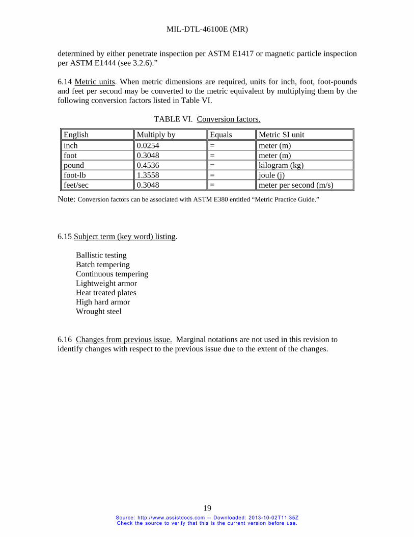
MIL-DTL-46100E (MR)
19
determined by either penetrate inspection per ASTM E1417 or magnetic particle inspection per ASTM E1444 (see 3.2.6).” 6.14 Metric units. When metric dimensions are required, units for inch, foot, foot-pounds and feet per second may be converted to the metric equivalent by multiplying them by the following conversion factors listed in Table VI.
TABLE VI. Conversion factors.
English Multiply by Equals Metric SI unit inch 0.0254 = meter (m) foot 0.3048 = meter (m) pound 0.4536 = kilogram (kg) foot-lb 1.3558 = joule (j) feet/sec 0.3048 = meter per second (m/s)
Note: Conversion factors can be associated with ASTM E380 entitled “Metric Practice Guide.” 6.15 Subject term (key word) listing.
Ballistic testing Batch tempering Continuous tempering Lightweight armor Heat treated plates High hard armor Wrought steel
6.16 Changes from previous issue. Marginal notations are not used in this revision to identify changes with respect to the previous issue due to the extent of the changes.
Source: http://www.assistdocs.com -- Downloaded: 2013-10-02T11:35ZCheck the source to verify that this is the current version before use.

MIL-DTL-46100E (MR)
APPENDIX A
BALLISTIC TESTING OF ARMOR PLATE, STEEL, WROUGHT HIGH HARDNESS A.1 SCOPE A.1.1 This appendix covers the requirements for ballistic testing of high hardness steel armor plate. A.2 DEFINITIONS A.2.1 Fair impact. A fair impact is an impact resulting from the striking of the test plate by a projectile in normal flight (no yawing or tumbling) and separated from another impact or the edge of the plate, hole, crack, or spalled area by an undisturbed area of at least two test projectile diameters. A.2.2 Witness sheet. A witness sheet is normally a 0.014 inch thick sheet of 5052 H36 aluminum alloy (or a 0.020 inch thick sheet of 2024 -T3 aluminum alloy) placed 6 inches (+ 0.5 inch) behind and parallel to the test plate or other ballistic sample. A.2.3 Complete penetration, protection, CP(P). A protection complete penetration is a penetration in which the projectile or one or more fragments of the projectile or plate pass beyond the back of the test plate and perforates the witness plate. A.2.4 Partial penetration, protection, PP(P). A partial penetration is any impact that is not a complete penetration. A.2.5 Gap. The difference in velocity between the high partial penetration velocity and the low complete penetration velocity used in computing the ballistic limit where the high partial penetration velocity is lower than the low complete penetration velocity. A.2.6 V50 protection ballistic limit, BL(P). The protection V50 ballistic limit is defined as the average of 6 fair impact velocities comprising the three lowest velocities resulting in complete penetration and the three highest velocities resulting in partial penetration. A maximum spread of 150 feet per second (fps) shall be permitted between the lowest and highest velocities employed in determination of ballistic limits. In only those cases where the lowest complete penetration velocity is lower than the highest partial penetration velocity by more than 150 fps shall the ballistic limit be based on 10 velocities (the 5 lowest velocities that resulted in complete penetration and the 5 highest velocities that resulted in partial penetrations). When the 10-round excessive spread, ballistic limit is used, the velocity spread shall be reduced to the lowest practical level (as close to 150 fps as possible). When a 10-round ballistic limit is used, this shall be noted in all reports. The normal up-and-down firing method shall be used in the determination of all BL(P)'s, all velocities being corrected to striking velocity. In the event that the ballistic limit computed is less than 30 fps above the minimum required and if a gap (high partial penetration velocity below the low complete penetration velocity) of 30 fps or more exists, firing shall
20 Source: http://www.assistdocs.com -- Downloaded: 2013-10-02T11:35ZCheck the source to verify that this is the current version before use.
MIL-DTL-46100E (MR)
APPENDIX A
continue as needed to reduce this gap to 25 fps or less. (This procedure shall insure better evaluation of the steel when the ballistic limit is near the minimum required.) A.2.7 Thickness, impact area. The thickness of ballistic test plates used for determining ballistic limits shall be that of the area subjected to the ballistic testing. A.3 REQUIREMENTS A.3.1 Resistance to penetration. The minimum ballistic limits shall be in accordance with the values shown in Tables A-I, A-II, A-III, A-IV or A-V, as applicable. A.3.2 Resistance to cracking. Ballistic test plates when visually examined after testing shall not develop any through-crack greater in length than five calibers of the projectile. A.4 TESTS A.4.1 Ballistic tests. V50 ballistic tests shall be performed in accordance with USADTC TOP 2-2-710, Ballistic Tests of Armor Materials or ITOP 2-2-713, Ballistic Testing of Armor to determine compliance with the requirements of Tables A-I through A-V. A.4.1.1 Plate thickness. Plate thickness as measured by the ballistic test agency shall be used to determine the required ballistic limit for the plate. Individual thickness measurements are to be read from a micrometer to the nearest 0.001 inch and the average of these readings reported to the nearest 0.001 inch. At least one measurement shall be taken along each edge of the plate at a distance of at least one inch from the edge, but preferably in the area which shall be impacted. The average of the measurements to the nearest 0.001 inch shall be used to determine the minimum ballistic limit requirements in the appropriate tables (Tables A-I through A-V). The required ballistic limit shall be determined by interpolation, if necessary, in the Tables in the Appendix. A.4.1.2 Rejection and retest of ballistic plates. A.4.1.2.1 First article tests (rejection). Unless noted otherwise in the contract or order, failure of either of the first article test plates to meet the minimum ballistic requirements as specified in the Appendix to this specification indicates failure of the product and process. A.4.1.2.2 First article (retests). Resubmission of ballistic retest plates shall not be made until the manufacturer has made the necessary corrections in the processing of the material to the satisfaction of the procuring activity. Two retest plates must be submitted for first article testing and both must pass. A.4.1.2.3 Acceptance tests (rejection). Unless otherwise noted in the contract or order, failure of a test plate to meet the ballistic requirements indicates failure of the lot, however, the final decision shall depend on the outcome of retests, if submitted.
21 Source: http://www.assistdocs.com -- Downloaded: 2013-10-02T11:35ZCheck the source to verify that this is the current version before use.

MIL-DTL-46100E (MR)
APPENDIX A
A.4.1.2.4 Acceptance tests (retests). If a test plate representing a lot fails to meet the ballistic requirements, the manufacturer has the following options. Immediately upon notification of the failure:
(1) At manufacturer’s expense submit two additional test plates from the same lot for ballistic retest, or
(2) First reheat treat (quenching and tempering) the lot and then submit a test plate from the retreated lot, or
(3) Scrap the lot and submit a plate representing a new lot for acceptance. If the manufacturer chooses any one of these options and the ballistic retest plate (or plates) meets the requirements, then the lot represented is acceptable. If option (1) is chosen and one or both of the retest plates fail, the manufacturer may reheat treat the lot and submit a test plate from the retreated lot. If this plate fails, the lot is rejected. If option (3) is chosen and the test plate fails, any one of the three options may be chosen again. The manufacturer shall report the processing used on the failed plates. A.4.1.3 Disposition of ballistic test plates. A.4.1.3.1 First article test plates. Upon request of the applicant within 15 days after ballistic testing, first article plates shall be returned "as is" to the applicant, at his expense, unless the plates were destroyed in testing. A.4.1.3.2 Acceptance test plates. Acceptance test plates that comply with the requirements of this specification are considered as part of the lot of steel they represent and ownership of them passes to the Government with the acceptance of that lot. Acceptance test plates that fail to comply with the requirements of this specification are considered as part of the lot they represent and remain the property of the producer just as the rejected lot does. The failed plates shall be returned, upon request, as in A.4.1.3.1.
22 Source: http://www.assistdocs.com -- Downloaded: 2013-10-02T11:35ZCheck the source to verify that this is the current version before use.

MIL-DTL-46100E (MR)
APPENDIX A
TABLE A-I. Minimum required ballistic limits - caliber .30 AP M2 projectile at 30 degrees obliquity.
Thickness
inches Required
BL(P), ft/sec Thickness
inches Required
BL(P), ft/sec Thickness
inches Required
BL(P), ft/sec
0.100 616 0.180 1647 0.265 2329 0.105 694 0.185 1697 0.270 2359 0.110 770 0.190 1746 0.275 2389 0.115 845 0.195 1793 0.280 2418
0.118 1/ 889 0.200 1839 0.285 2447 0.120 917 0.205 1884 0.290 2474 0.125 988 0.210 1927 0.295 2501 0.130 1057 0.215 1969 0.300 2/ 2527 0.135 1123 0.220 2010 0.305 2553 0.140 1188 0.225 2050 0.310 2578 0.145 1251 0.230 2088 0.315 2603 0.150 1313 0.235 2126 0.320 2627 0.155 1373 0.240 2162 0.325 2650 0.160 1431 0.245 2197 0.330 2674 0.165 1487 0.250 2232 0.335 2697 0.170 1542 0.255 2265 0.340 2719 0.175 1595 0.260 2297
1/ Specification requirements begin for this ordered thickness. 2/ Specification requirements end for this ordered thickness.
Note: Tabulated values on either side of the ordered thicknesses are for interpolation of BL(P) requirements on undersize or oversize plates.
23 Source: http://www.assistdocs.com -- Downloaded: 2013-10-02T11:35ZCheck the source to verify that this is the current version before use.

MIL-DTL-46100E (MR)
APPENDIX A
TABLE A-II. Minimum required ballistic limits - caliber .50 AP M2 projectile at 30 degrees obliquity.
Thickness
inches Required
BL(P), ft/sec Thickness
inches Required
BL(P), ft/secThickness
inches Required
BL(P), ft/sec
0.290 1783 0.400 2151 0.515 2481 0.295 1801 0.405 2166 0.520 2494 0.300 1820 0.410 2182 0.525 2508
0.301 1/ 1823 0.415 2197 0.530 2521 0.305 1837 0.420 2212 0.535 2534 0.310 1855 0.425 2227 0.540 2547 0.315 1873 0.430 2242 0.545 2560 0.320 1890 0.435 2256 0.550 2573 0.325 1907 0.440 2271 0.555 2586 0.330 1925 0.445 2286 0.560 2599 0.335 1942 0.450 2300 0.565 2612 0.340 1958 0.455 2314 0.570 2625 0.345 1975 0.460 2329 0.575 2638 0.350 1992 0.465 2343 0.580 2650 0.355 2008 0.470 2357 0.585 2663 0.360 2025 0.475 2371 0.590 2/ 2675 0.365 2041 0.480 2385 0.595 2688 0.370 2057 0.485 2399 0.600 2700 0.375 2073 0.490 2413 0.605 2713 0.380 2089 0.495 2427 0.610 2725 0.385 2104 0.500 2440 0.615 2737 0.390 2120 0.505 2454 0.620 2750 0.395 2136 0.510 2468 0.625 2762
1/ Specification requirements begin for this ordered thickness. 2/ Specification requirements end for this ordered thickness.
Note: Tabulated values on either side of the ordered thicknesses are for interpolation of BL(P) requirements on undersize or oversize plates.
24 Source: http://www.assistdocs.com -- Downloaded: 2013-10-02T11:35ZCheck the source to verify that this is the current version before use.

MIL-DTL-46100E (MR)
APPENDIX A
TABLE A-III. Minimum required ballistic limits – 14.5 mm API B32 projectile at 30 degrees obliquity.
Thickness
inches Required
BL(P), ft/sec Thickness
inches Required
BL(P), ft/secThickness
inches Required
BL(P), ft/sec
0.575 2320 0.645 2469 0.720 2621 0.580 2331 0.650 2480 0.725 2630 0.585 2342 0.655 2490 0.730 2640 0.590 2353 0.660 2500 0.735 2650
0.591 1/ 2355 0.665 2511 0.740 2659 0.595 2364 0.670 2521 0.745 2669 0.600 2374 0.675 2531 0.750 2679 0.605 2385 0.680 2541 0.755 2688 0.610 2396 0.685 2551 0.760 2698 0.615 2407 0.690 2561 0.765 2/ 2707 0.620 2417 0.695 2571 0.770 2717 0.625 2428 0.700 2581 0.775 2726 0.630 2438 0.705 2591 0.780 2736 0.635 2449 0.710 2601 0.785 2745 0.640 2459 0.715 2611 0.790 2754
1/ Specification requirements begin for this ordered thickness. 2/ Specification requirements end for this ordered thickness.
Note: Tabulated values on either side of the ordered thicknesses are for interpolation of BL(P) requirements on undersize or oversize plates.
25 Source: http://www.assistdocs.com -- Downloaded: 2013-10-02T11:35ZCheck the source to verify that this is the current version before use.

MIL-DTL-46100E (MR)
APPENDIX A
TABLE A-IV. Minimum required ballistic limits – 14.5 mm API BS41 projectile at 30 degrees obliquity.
Thickness
inches Required
BL(P), ft/sec Thickness
inches Required
BL(P), ft/secThickness
inches Required
BL(P), ft/sec
0.740 2212 0.880 2564 1.025 2886 0.745 2225 0.885 2576 1.030 2896 0.750 2239 0.890 2588 1.035 2907 0.755 2252 0.895 2599 1.040 2917 0.760 2265 0.900 2611 1.045 2927 0.765 2278 0.905 2622 1.050 2938
0.766 1/ 2281 0.910 2634 1.055 2948 0.770 2292 0.915 2645 1.060 2958 0.775 2305 0.920 2657 1.065 2968 0.780 2318 0.925 2668 1.070 2979 0.785 2331 0.930 2679 1.075 2988 0.790 2343 0.935 2690 1.080 2998 0.795 2356 0.940 2702 1.085 3008 0.800 2369 0.945 2713 1.090 3018 0.805 2382 0.950 2724 1.095 3027 0.810 2394 0.955 2735 1.100 3036 0.815 2407 0.960 2746 1.105 3046 0.820 2419 0.965 2757 1.110 3056 0.825 2431 0.970 2768 1.115 3065 0.830 2444 0.975 2779 1.120 3075 0.835 2456 0.980 2790 1.125 3084 0.840 2468 0.985 2800 1.130 2/ 3094 0.845 2481 0.990 2811 1.135 3103 0.850 2493 0.995 2822 1.140 3112 0.855 2505 1.000 2832 1.145 3122 0.860 2517 1.005 2843 1.150 3131 0.865 2529 1.010 2854 1.155 3140 0.870 2540 1.015 2865 1.160 3149 0.875 2552 1.020 2875 1.165 3158
1/ Specification requirements begin for this ordered thickness. 2/ Specification requirements end for this ordered thickness.
Note: Tabulated values on either side of the ordered thicknesses are for interpolation of BL(P) requirements on undersize or oversize plates.
26 Source: http://www.assistdocs.com -- Downloaded: 2013-10-02T11:35ZCheck the source to verify that this is the current version before use.

MIL-DTL-46100E (MR)
APPENDIX A
TABLE A-V. Minimum required ballistic limits – 20 mm API-T M602 projectile at 0 degrees obliquity.
Thickness inches
Required BL(P), ft/sec
Thickness inches
Required BL(P), ft/sec
Thickness inches
Required BL(P), ft/sec
1.070 1848 1.245 2135 1.425 2396 1.075 1857 1.250 2143 1.430 2402 1.080 1866 1.255 2150 1.435 2409 1.085 1874 1.260 2158 1.440 2416 1.090 1883 1.265 2165 1.445 2423 1.095 1892 1.270 2173 1.450 2430 1.100 1900 1.275 2180 1.455 2436 1.105 1909 1.280 2188 1.460 2443 1.110 1917 1.285 2195 1.465 2450 1.115 1926 1.290 2203 1.470 2457 1.120 1934 1.295 2210 1.475 2463 1.125 1943 1.300 2218 1.480 2470 1.130 1951 1.305 2225 1.485 2477
1.131 1/ 1953 1.310 2232 1.490 2483 1.135 1959 1.315 2240 1.495 2490 1.140 1968 1.320 2247 1.500 2496 1.145 1976 1.325 2254 1.505 2503 1.150 1984 1.330 2262 1.510 2510 1.155 1992 1.335 2269 1.515 2516 1.160 2001 1.340 2276 1.520 2523 1.165 2009 1.345 2283 1.525 2529 1.170 2017 1.350 2290 1.530 2536 1.175 2025 1.355 2298 1.535 2542 1.180 2033 1.360 2305 1.540 2549 1.185 2041 1.365 2312 1.545 2555 1.190 2049 1.370 2319 1.550 2561 1.195 2057 1.375 2326 1.555 2568 1.200 2065 1.380 2333 1.560 2574 1.205 2073 1.385 2340 1.565 2581 1.210 2081 1.390 2347 1.570 2587 1.215 2088 1.395 2354 1.575 2593 1.220 2096 1.400 2361 1.580 2600 1.225 2104 1.405 2368 1.585 2606 1.230 2112 1.410 2375 1.590 2612 1.235 2120 1.415 2382 1.595 2619 1.240 2127 1.420 2389 1.600 2625
1/ Specification requirements begin for this ordered thickness.
Note: Tabulated values on either side of the ordered thicknesses are for interpolation of BL(P) requirements on undersize or oversize plates.
27 Source: http://www.assistdocs.com -- Downloaded: 2013-10-02T11:35ZCheck the source to verify that this is the current version before use.

MIL-DTL-46100E (MR)
APPENDIX A
28
TABLE A-V. Minimum required ballistic limits - 20 mm API-T M602 projectile at 0 degrees obliquity – Continued.
Thickness inches
Required BL(P), ft/sec
Thickness inches
Required BL(P), ft/sec
Thickness inches
Required BL(P), ft/sec
1.605 2631 1.770 2831 1.935 3017 1.610 2637 1.775 2836 1.940 3023 1.615 2644 1.780 2842 1.945 3028 1.620 2650 1.785 2848 1.950 3033 1.625 2656 1.790 2854 1.955 3039 1.630 2662 1.795 2860 1.960 3044 1.635 2669 1.800 2865 1.965 3050 1.640 2675 1.805 2871 1.970 3055 1.645 2681 1.810 2877 1.975 3061 1.650 2687 1.815 2883 1.980 3066 1.655 2693 1.820 2888 1.985 3071 1.660 2699 1.825 2894 1.990 3077 1.665 2705 1.830 2900 1.995 3082 1.670 2711 1.835 2905 2.000 2/ 3088 1.675 2718 1.840 2911 2.005 3093 1.680 2724 1.845 2917 2.010 3098 1.685 2730 1.850 2922 2.015 3104 1.690 2736 1.855 2928 2.020 3109 1.695 2742 1.860 2934 2.025 3114 1.700 2748 1.865 2939 2.030 3120 1.705 2754 1.870 2945 2.035 3125 1.710 2760 1.875 2951 2.040 3130 1.715 2766 1.880 2956 2.045 3135 1.720 2772 1.885 2962 2.050 3141 1.725 2778 1.890 2967 2.055 3146 1.730 2784 1.895 2973 2.060 3151 1.735 2789 1.900 2978 2.065 3156 1.740 2795 1.905 2984 2.070 3162 1.745 2801 1.910 2990 2.075 3167 1.750 2807 1.915 2995 2.080 3172 1.755 2813 1.920 3001 2.085 3177 1.760 2819 1.925 3006 2.090 3183 1.765 2825 1.930 3012
2/ Specification requirements end for this ordered thickness.
Note: Tabulated values on either side of the ordered thicknesses are for interpolation of BL(P) requirements on undersize or oversize plates.
Source: http://www.assistdocs.com -- Downloaded: 2013-10-02T11:35ZCheck the source to verify that this is the current version before use.

MIL-DTL-46100E (MR)
CONCLUDING MATERIAL Custodian: Preparing activity: Army - MR Army - MR Review activities: Project 9515-2007-007 Army - AR, AT, TE DLA - IS NOTE: The activities listed above were interested in this document as of the date of this document. Since organizations and responsibilities can change, you should verify the currency of the information above using the ASSIST Online database at http://assist.daps.dla.mil/.
29 Source: http://www.assistdocs.com -- Downloaded: 2013-10-02T11:35ZCheck the source to verify that this is the current version before use.