MIL-DTL-38999, Series I LJT, II JT, III TV, HD · 2 Contact Amphenol Aerospace for more information...
27
2 Contact Amphenol Aerospace for more information at 800-678-0141 • www.amphenol-aerospace.com 38999 III SJT I II Access Aquacon MIL-DTL- 27599 Hermetics Contact Size JT II LJT I TV III III JT/LJT Solder Crimp Class H Class Y TV* Service Rating Total Contacts 23 HD 22D 22M 22 20 16 12 12 (Coax) 10 (Power) 8 (Coax) 8†† (Twinax) 8-2n P M 2 2 8-3n X NA P P M 3 3 9-3n X 9-5Hn Grounded 1 1 8-6 X X P P M 6 6 9-6 X X P P 9-7n X M 7 7 9-9n N 9 9 9-22n X I 2 2 8-35 X P P M 6 6 9-35 9-35 A35 X P P P 8-44 X P P M 4 4 9-44 X 9-94n u M 2 2 8-97n X M 4 2 2 8-98 S X P P I 3 3 9-98 9-98 A98 X X P P P 11-2H 11-2H B2 X P** I 2 2 10-4 3 I 4 4 11-4 11-4 X 2 10-5 X X P P I 5 5 11-5 11-5 B5 X X P 11-6n S I 6 6 10-13 X X P/S P/S M 13 13 11-13 X X P/S P/S 11-19n N 19 19 10-35 X P/S P/S M 13 13 11-35 11-35 B35 X P/S P/S P 11-54n X u II 4 4 10-98 X X P/S P/S I 6 6 11-98 11-98 B98 X X P/S P/S P 10-99 X P P I 7 7 11-99 11-99 B99 X X P 12-3 X X u P P II 3 3 13-3n P 12-4 X X P P I 4 4 13-4H 13-4H C4 X X P P P 12-8 X X P P I 8 8 13-8 13-8 C8 X X P P P 13-13n I, Fiber Optic 4 2** 2 12-22 X P/S P/S M 22 22 13-22 X X P/S P/S 13-26n 2 M 8 6 2 13-32n N 32 32 12-35 X P/S P/S M 22 22 13-35 13-35 C35 X P/S P/S P 13-63n u l 4 2 2 12-98 X X P/S P/S I 10 10 13-98 13-98 C98 X X P/S P/S P 15-ATn X I 13 10 3 14-4n 2 I 4 4 15-4n 15-4n 2 u 14-5 X X P P II 5 5 15-5H 15-5H D5 X X P P P MIL-DTL-38999, Series I LJT, II JT, III TV, HD Insert Availability and Identification Chart Series Series Series Military X Completely tooled. + Majority of tooling is completed (contact Amphenol Aerospace for availability). u Not tooled for 02-R. P Available with Pin contacts only S Available with Socket contacts only P/S Available with Pin contacts or Socket contacts H Ground plane proprietary option available. Arrg. 9-5 is exclusively ground plane type. n Not Mil-Qualified. G 21-75 is Mil-Qualified with twinax contacts only. Note: MS connector 21-75 is supplied with size 8 twinax. Commercial connector 21-75 is supplied with size 8 coax. HD designates High Density 38999 Series III insert patterns which use size 23 contacts only. Not rated over 175°C. * Hermetic inserts - solder termination standard. (Contact Amphenol Aerospace for optional PCB or eyelet termination). ** Two size 16 contacts dedicated to fiber optics. See the Fiber Optic section for more information. *** For use in MIL-STD-1760 applications (see pages 75 and 76). † For RG 180/U and RG 195/U cables only. †† Size 8 Coax and Twinax are interchangeable. (2) Not Tooled for RP or 02RE (3) Pin inserts only, not tooled for RP or 02RE (Consult Amphenol Aerospace for avail.) (5) MS Connector 21-79 has provision for two size 8 coax contacts. Coax contacts are not supplied unless specified by customer.
Transcript of MIL-DTL-38999, Series I LJT, II JT, III TV, HD · 2 Contact Amphenol Aerospace for more information...

2 Contact Amphenol Aerospace for more information at 800-678-0141 • www.amphenol-aerospace.com
38999 III
SJT
I
II
Access
Aquacon
MIL-DTL-27599
Hermetics Contact Size
JT II LJT I TV III III JT/LJTSolder
Crimp ClassH
ClassY
TV* Service Rating
Total Contacts
23HD
22D 22M 22 20 16 12 12(Coax)
10(Power)
8(Coax)
8††(Twinax)
8-2n P M 2 28-3n X NA P P M 3 39-3n X
9-5Hn Grounded 1 18-6 X X P P M 6 69-6 X X P P
9-7n X M 7 79-9n N 9 9
9-22n X I 2 28-35 X P P M 6 69-35 9-35 A35 X P P P8-44 X P P M 4 49-44 X
9-94n u M 2 28-97n X M 4 2 28-98 S X P P I 3 39-98 9-98 A98 X X P P P
11-2H 11-2H B2 X P** I 2 210-4 3 I 4 411-4 11-4 X 210-5 X X P P I 5 511-5 11-5 B5 X X P
11-6n S I 6 610-13 X X P/S P/S M 13 1311-13 X X P/S P/S
11-19n N 19 1910-35 X P/S P/S M 13 1311-35 11-35 B35 X P/S P/S P
11-54n X u II 4 410-98 X X P/S P/S I 6 611-98 11-98 B98 X X P/S P/S P10-99 X P P
I 7 711-99 11-99 B99 X X P
12-3 X X u P PII 3 3
13-3n P12-4 X X P P
I 4 413-4H 13-4H C4 X X P P P
12-8 X X P PI 8 813-8 13-8 C8 X X P P P
13-13nI, Fiber Optic 4 2** 2
12-22 X P/S P/S M 22 2213-22 X X P/S P/S13-26n 2 M 8 6 213-32n N 32 32
12-35 X P/S P/S M 22 2213-35 13-35 C35 X P/S P/S P13-63n u l 4 2 2
12-98 X X P/S P/S I 10 1013-98 13-98 C98 X X P/S P/S P15-ATn X I 13 10 3
14-4n 2I 4 4
15-4n 15-4n 2 u
14-5 X X P PII 5 515-5H 15-5H D5 X X P P P
MIL-DTL-38999, Series I LJT, II JT, III TV, HDInsert Availability and Identification Chart
Series Series Series Military
X Completely tooled. + Majority of tooling is completed
(contact Amphenol Aerospace for availability).u Not tooled for 02-R.P Available with Pin contacts onlyS Available with Socket contacts onlyP/S Available with Pin contacts or Socket contactsH Ground plane proprietary option available. Arrg. 9-5 is exclusively
ground plane type. n Not Mil-Qualified.G 21-75 is Mil-Qualified with twinax contacts only.
Note: MS connector 21-75 is supplied with size 8 twinax. Commercial connector 21-75 is supplied with size 8 coax.
HD designates High Density 38999 Series III insert patterns which use size 23 contacts only. Not rated over 175°C.
* Hermetic inserts - solder termination standard. (Contact Amphenol Aerospace for optional PCB or eyelet termination).
** Two size 16 contacts dedicated to fiber optics. See the Fiber Optic section for more information.
*** For use in MIL-STD-1760 applications (see pages 75 and 76).† For RG 180/U and RG 195/U cables only.†† Size 8 Coax and Twinax are interchangeable.(2) Not Tooled for RP or 02RE(3) Pin inserts only, not tooled for RP or 02RE (Consult Amphenol
Aerospace for avail.)(5) MS Connector 21-79 has provision for two size 8 coax contacts.
Coax contacts are not supplied unless specified by customer.

3Contact Amphenol Aerospace for more information at 800-678-0141 • www.amphenol-aerospace.com
38999 III
SJT
I
II
Access
Aquacon
MIL-DTL-38999, Series I LJT, II JT, III TV, HDInsert Availability and Identification Chart
MIL-DTL-27599
Hermetics Contact Size
JT II LJT I TV III III JT/LJTSolder
Crimp Class H
ClassY
TV* Service Rating
Total Contacts
23HD
22D 22M 22 20 16 12 12(Coax)
8(Coax)
8††(Twinax)
4
14-15 X X P P I15 14 1
15-15 15-15 D15 X X P/S P/S P I14-18 X X P/S P/S
I 18 1815-18 15-18 D18 X X P/S P/S P
14-19n X XI 19 19
15-19 15-19 D19 X P P P14-35 X P P
M 37 3715-35 15-35 D35 X P/S P/S P
14-37 X X P PM 37 37
15-37 X X P P15-55n N 55 55
14-68n 2 P P1 8 8
15-68n X X14-97 X P P
I 12 8 415-97 15-97 D97 X X P P P17-2 17-2 E2 X u M 39 38 1
17-EAn M 19 10 3 2 417-ECn M 41 32 9
16-6 X P PI 6 6
17-6 17-6 E6 X P P P16-8 X X P P
II 8 817-8H 17-8H E8 X X P/S P/S P
16-13n 2I 13 13
17-13n 217-22n 17-22Hn u Coax 4 2 217-25n 17-25n 2 M 24 22 2
16-26 X X P/S P/SI 26 26
17-26 17-26 E26 X X P/S P/S P16-35 X P P
M 55 5517-35 17-35 E35 X X P P P
16-42 XM 42 42
17-42n P17-52n X u M 2 2
16-55 X X P/S P/SM 55 55
17-55 X X P/S P/S17-60n X I/Coax 10 8 217-73n N 73 73
16-99 X X P PI 23 21 2
17-99 17-99 E99 X X P P19-ADn X u Inst. 17 16 119-FAn M 23 6 8 7 2
18-11 X X P PII 11 11
19-11H 19-11H F11 X X P P P19-18 19-18 F18 2 2 M 18 14 4
18-28 X XI 28 26 2
19-28n 19-28 F28 X P X18-30 X X
I 30 29 119-30n X P
19-31n X M 15 12 1 218-32 X X P/S P/S
I 32 3219-32 19-32 F32 X X P/S P/S P
18-35 X P PM 66 66
19-35 19-35 F35 X P P P18-53 X X
M 53 5319-53n P
18-66 X X P PM 66 66
19-66 X P P19-67n X 3 S S M 67 67
18-68n 2I 18 18
19-68n 19-68n 3 S18-96n 2 I 9 9
19-88n N 88 8820-1 X P P
M 79 7921-1 X P/S P/S
Series Series Series Military

4 Contact Amphenol Aerospace for more information at 800-678-0141 • www.amphenol-aerospace.com
38999 III
SJT
I
II
Access
Aquacon
MIL-DTL-27599
Crimp Hermetics Service Rating
Total Contact Size
JT II LJT I TV III III JT/LJTSolder
H Y TV* 23HD
22D 22M 22 20 16 16 (Cx)
12 12(Cx)
10(Power)
8(Power)
8(Cx)
8††(Twinax)
4
20-2 X M 65 6521-2n X20-11n 3 I 11 1121-11H 21-11H G11 X20-16 X X P/S P/S
II 16 1621-16H 21-16H G16 X X P P P21-25n I 25 2521-27n X I 27 27
21-29n X I 27 19 4 420-35 X P P M 79 7921-35 21-35 G35 X P/S P/S P20-39 X X P P I 39 37 221-39 21-39 G39 X X P P P20-41 X X P P
I 41 4121-41 21-41 G41 X X P/S P/S P21-48n M 4 4
21-75H 21-75HG G75 2 X N M 4 4 (4) 21-79n 21-79n 2 X II 19 17 2 (2)
21-121n N 121 12122-1 X P/S P/S
M 100 10023-1 X P P
22-2 X X P PM 85 85
23-2 X X P P23-6Hn 23-6Hn X P M 6 6
22-14n 2 uI 14 14
23-14n 23-14n 2 u
22-21 X X P PII 21 21
23-21H 23-21H H21 X X P P P22-32 X X P P
I 32 3223-32n X P23-34n X I 34 34
22-35 X P/S P/S M 100 10023-35 23-35 H35 X P P P
22-53n P I 53 5323-53 23-53 H53 X X P/S P/S P
23-54 n X M 53 40 9 422-55 X X P P I 55 55
23-55 23-55 H55 X P23-63 n S M 57 49 4 4
23-97n X II 16 1623-99n X II 11 11
23-151 n N 151 15124-1 X P P
M 128 12825-1 X P P
24-2 XM 100 100
25-2 X24-4 X P P I 56 48 825-4 25-4 J4 X P
25-7n 25-7 J7 X M Twx 99 97 225-8H J8 u Twinax 8 825-11*** J11 2 u N 11 2 925-16n M 8 6 225-17n u M 42 36 6
24-19n X P PI 19 1925-19H 25-19H J19 X P
25-20n 25-20*** J20 2 u N 30 10 13 4 3
MIL-DTL-38999, Series I LJT, II JT, III TV, HDInsert Availability and Identification Chart
X Completely tooled.+ Majority of tooling is completed
(contact Amphenol Aerospace for availability).u Not tooled for 02-R.P Available with Pin contacts onlyS Available with Socket contacts onlyP/S Available with Pin contacts or Socket contactsH Ground plane proprietary option available. Arrg. 9-5, 26-62 is exclusively
ground plane type. n Not Mil-Qualified.G 21-75 is Mil-Qualified with twinax contacts only. * Hermetic inserts - solder termination standard. (Contact Amphenol
Aerospace for optional PCB or eyelet termination).
HD designates High Density 38999 Series III insert patterns which use size 23 contacts only. Not rated over 175°C.
** Two size 16 contacts dedicated to fiber optics. See the Fiber Optic Section for more information.
*** For use in MIL-STD-1760 applications (see pages 75 and 76).† For RG 180/U and RG 195/U cables only.†† Size 8 Coax and Twinax are interchangeable.(2) Not Tooled for RP or 02RE(3) Pin inserts only, not tooled for RP or 02RE (Consult Amphenol for avail.)(4) MS connector 21-75 is supplied with size 8 twinax.
Commercial connector 21-75 is supplied with size 8 coax.(5) MS Connector 21-79 has provision for two size 8 coax contacts.
Coax contacts are not supplied unless specified by customer.(PWR) Suffix at end of part number to replace coax, twinax, and fiber contacts
with power contacts.
Series Series Series Military

5Contact Amphenol Aerospace for more information at 800-678-0141 • www.amphenol-aerospace.com
38999 III
SJT
I
II
Access
Aquacon
(Insert arrangements requiring non-standard shells)
X Completely tooled.+ Majority of tooling is completed (contact
Amphenol Aerospace for availability).u Not tooled for 02-R.P Pin inserts only (contact Amphenol Aerospace
for socket availability).H Ground plane proprietary option available.
Arrangement 9-5, 25-62 is exclusively ground plane type.
n Not Mil-Qualified.* Hermetic inserts - solder termination standard.
(Contact Amphenol Aerospace for optional PCB or eyelet termination).
** Two size 16 contacts dedicated to fiber optics.See the Fiber Optic section for more information.
*** For use in MIL-STD-1760 applications (pgs. 75 and 76).
† For RG 180/U and RG 195/U cables only.†† Size 8 Coax and Twinax are interchangeable.Note: 25L-3 and 25L-7 use longer shells.(PWR) Suffix at end of part number to replace coax,
twinax, and fiber contacts with power contacts.
SELECT NON-STANDARD SHELL SIZE- Special Insert Arrangement
Contact Size
Shell Size-Insert Arrg.
Crimp Hermetics* Service Rating
Total Contacts
Comments 22D 20 16 12
9-2 X I 2 Formerly Pyle 215-4 X II 4 Formerly Pyle 4
15-25 X M 25 Formerly Pyle 22 317-20 X M 20 Formerly Pyle 16 421-12 X I 12 Formerly Pyle 3 921-21 X M/Inst. 41 Improved sealing 32 921-99 X M 16 Formerly Pyle 5 1125-92 X M 101 Formerly Pyle 92 925-97 X M 42 Formerly Pyle 26 3 13
Contact Size
Shell Size- Insert Arrg.
Crimp Hermetics* Service Rating
Total Con-tacts
22D 20 8 4 0
25L-3 X II 3 1 225L-7 X II 7 733-3 X II 3 1 233-5 X II 5 533-6 X II 6 2 437-5 X II 4 4
SELECT SHELL SIZE - SPECIAL INSERT ARRANGEMENT (Not Mil-Spec Qualified)
MIL-DTL-27599
HermeticsContact Size
JT II LJT I TV III III JT/LJTSolder
Crimp H Y TV* Service Rating
Total Contacts
23HD
22D 20 16 12 (Fiber)
12 12 (Coax)
10 8(Coax)
8††(Twinax
8Quadrax
4
24-24 X P PI 24 12 12
25-24H 25-24H J24 X P P25-26nH F I 25 16 5 4
24-29 XI 29 29
25-29H 25-29H J29 X X24-35 X P P New
128 12825-35 25-35 J35 X P P P M
24-37 XI 37 37
25-37H 25-37H J37 X25-41n N Inst. 41 22 3 11 2 3
24-43n 3I 43 23 20
25-43 25-43 J43 X 2 u
25-46 25-46 J46 2 u I 46 40 4 224-61 X X P P
I 61 6125-61 25-61 J61 X X P P P
25-62 nH X u I 12 8 425-90 J90 u I 46 40 4 225-187 n N 187 18725-1A n N 8 4 425-AT n X M 60 31 12 11 2 2 225-F4 n X M/I 66 49 13 4
TV SERIES III
MIL-DTL-38999, Series I LJT, II JT, III TV, HD Insert Availability and Identification Chart
Series Series Series Military
Contact Size
Shell Size-Insert Arrg.
Crimp Service Rating
Total Contacts
Comments 22D 20 16 12
25-64 X 64 Formerly Pyle 40 8 10 6
LJT SERIES ISELECT SHELL SIZE - SPECIAL INSERT ARRANGEMENT (Not Mil-Spec Qualified)

6 Contact Amphenol Aerospace for more information at 800-678-0141 • www.amphenol-aerospace.com
38999 III
SJT
I
II
Access
Aquacon
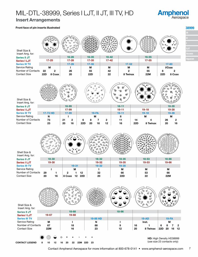
Front face of pin inserts illustrated
MIL-DTL-38999, Series I LJT, II JT, III TV, HD Insert Arrangements
CONTACT LEGEND 8 10 12 16 20 22 22M 22D 23
AB
A
B
C 12
3
45
61
2
345
67
82
197
35 4
6
A
B
51
64
3
21
23
4
B AA
BC
DC A
B
AB
8-2 8-3 8-6 8-35 8-44 8-97 8-989-3 9-6 9-7 9-22 9-35 9-44 9-98 11-2
9-5 9-9 HD 9-35 9-94 9-98 11-2M M Grounded M M N I M M M M I I2 3 1 6 7 9 2 6 4 2 2 2 3 220 20 8 Twinax 22M 22M 23 20 22D 22 20 22M 20 20 16
12
13
19
18
17
16 15
149
8
4
5
6
10
111
2
3
1413
12 11 10
2829
3015
16
25
2627
3839
414036
24
35
3433
20
32
31
17
1819
21 2223
37
98
7
6
5
4
321 1
6
11
17
30
A
B
C
D
E
F
A
B
C
DE
F
G
H
AB
C
D
EF
G
H
J
K
LN M
A
D
C
B
16-6 16-8 16-1317-2 17-6 17-8 17-13 17-22
17-EA 17-EC 17-2 17-6 17-8 17-22M I II I Coax
10 3 2 4 32 9 38 1 6 8 13 2 222D 20 16 12 22D 20 22D 8 Twinax 12 16 16 12 Coax 8 Coax
HD: High Density HD38999 (use size 23 contacts only)
AB
CD
E
FG
H 22
1
20
A
CDE
F B 1829
32
1 1
2122
AB
C
D
AB
C
DE
F
G
H
JK
A
10 76
53 4
BC
1
2
9 8
A
BC
DA
B
CD
E
12-8 12-22 12-35 12-98 14-4 14-513-8 13-22 13-35 13-98 15-4 15-513-8 13-26 13-32 HD 13-35 13-63 13-98 15-AT 15-4 15-5
I M M N M I I I I II8 22 6 2 32 22 2 2 10 10 3 4 520 22M 22D 12 23 22D 16 12 20 22D 12 12 16
A
BC
D A
BC
D
EA
B
CD
E
F1
2
3
456
7
8
910
11
1213
1 2
3
4
567
89
10 1716
1918
15
1413
1211
12
3
456
7
8
910
11
1213A
B
D
C
A
B
CD
E FA
B
CD
E
F
GA
B
C
A
B
C
D
10-4 10-5 10-13 10-35 10-98 10-99 12-3 12-411-4 11-5 11-6 11-13 11-35 11-98 11-99 13-3 13-411-4 11-5 11-19 HD 11-35 11-54 11-98 11-99 13-4
I I I M N M II I I II I4 5 6 13 19 13 4 6 7 3 420 20 20 22M 23 22D 22D 20 20 16 16
AB
C
DE
FG
H
J
KL
MN
P
R
A
B
C
D
EFG
H
J
KL
M N
P
RS
T U
AB
C
D
EFGH
J
K
LM
N P
R
ST
U V
321
13
12
11
4
5
6
78
910
1415
1617
181920
2322
21
24
25
1
2131
1
11
2131
39
16
241731253932
465247
40
5553
1041 A
B
C
DE
F
GH
AB
C
D
EFG
H
JK
L
M
14-15 14-18 14-19 14-35 14-37 14-68 14-9715-15 15-18 15-19 15-35 15-37 15-68 15-9715-15 15-18 15-19 15-25 15-35 15-55 HD 15-97
I I I M M M N I I14 1 18 19 22 3 37 37 55 8 8 420 16 20 20 22D 16 22D 22M 23 16 20 16
Shell Size & Insert Arrg. for:
Series II JTSeries I LJTSeries III TVService RatingNumber of ContactsContact Size
Shell Size & Insert Arrg. for:
Series II JTSeries I LJTSeries III TVService RatingNumber of ContactsContact Size
Shell Size & Insert Arrg. for:
Series II JTSeries I LJTSeries III TVService RatingNumber of ContactsContact Size
Shell Size & Insert Arrg. for:
Series II JTSeries I LJTSeries III TVService RatingNumber of ContactsContact Size
Shell Size & Insert Arrg. for:
Series II JTSeries I LJTSeries III TVService RatingNumber of ContactsContact Size
7Contact Amphenol Aerospace for more information at 800-678-0141 • www.amphenol-aerospace.com
38999 III
SJT
I
II
Access
Aquacon
Front face of pin inserts illustrated
MIL-DTL-38999, Series I LJT, II JT, III TV, HD Insert Arrangements
CONTACT LEGEND 8 10 12 16 20 22 22M 22D 23
HD: High Density HD38999 (use size 23 contacts only)
12
3
4
56
789
10
1112
13 14
15 16
17
1819
20
2122
23
24
AB
C
D
E
FGHJ
KL
M
N
P
RS T
U
V
WX
Y
Z
ab
c
1
3
4
9
10
16
17
24
25
31
32
39
40
47
46
52
53
55
1
21
42
41
31
11
A
B
1
3
4
9
10
16
17
2431
2532
39
40
46
47
52
53
55
1
5
28
9 310
7
6 4
16-26 16-35 16-42 16-5517-25 17-26 17-35 17-42 17-55
17-26 17-35 17-52 17-60M I M M M M I/Coax
22 2 26 55 42 2 55 8 222D 8 Coax 20 22D 22 8 Twinax 22M 22D 8 Coax
1 273
8 15
241625
33
4250
5967
72 73
7166
5849
4132
AB
C
D
E
FGHJ
KL
M
N
P
R
S TU
VWX
YZ
1
2
3
4
5
678
9
10
11
12
18
19 17
1623
15
22
20
21 14
13 A
B
C
D
E
F
G
H
J
K
L
A
B
C
DE
F
G
H
J
K
L
M
N
P
R
S
T
U
AB
C
D
E
FG
H
R
JK
LM
N
P
ST
UV
W
X
Y
Za
b
c
d
e
16-99 18-11 18-2817-99 19-11 19-18 19-28
17-73 HD 17-99 19-FA 19-11 19-18 19-28N I M II M M73 21 2 6 8 7 2 11 14 4 26 223 20 16 22D 20 16 12 16 22D 8 Twinax 20 16
AB
C
D
E
FG
HJKL
M
N
PR
S
TU
V
W
XY
Za
b
cd
e
g f
A
BC
EK
M
N
R
S
U
VW
gh
f AB
C
D
E
F
GH
JK
L
M
N
P
R
ST
UV
W
X
YZa
bc
d
ef
gh
j1
2
3
4
9
10
16
17
24
25
33
34
42
43
50
51
57
58
63
64
66
1
41
515253
3111
21
1
2
3
4
9
10
2416
1725
33
34
42
43
50
51
57
58
63
64
66
18-30 18-32 18-35 18-53 18-6619-30 19-32 19-35 19-53 19-66
19-31 19-32 19-35I M 1 M M M
29 1 2 1 12 32 66 53 6620 16 8 Coax 12 22D 20 22D 22 22M
1
3
4
9
10
16
17
24
25
34
35
43
44
51
52
58
59
64
65
67
ABL
CK
DJ
EH
FGR
U
M
T N
S P
1
88
84
73
55
31
30 A
BH
C
DF
E
G J
1215 314
13
12
4
5
11 8
710
16
89
A
12
13
19
18
17
16 15
149
8
4
5
6
10
111
2
3
18-68 18-9619-67 19-68
19-88 HD 19-AD 19-FAM I N I Inst. M67 18 88 9 16 1 6 8 7 2
22M 16 23 12 20 8 Twinax 22D 20 16 12
Shell Size & Insert Arrg. for:
Series II JTSeries I LJTSeries III TVService RatingNumber of ContactsContact Size
Shell Size & Insert Arrg. for:
Series II JTSeries I LJTSeries III TVService RatingNumber of ContactsContact Size
Shell Size & Insert Arrg. for:
Series II JTSeries I LJTSeries III TVService RatingNumber of ContactsContact Size
Shell Size & Insert Arrg. for:
Series II JTSeries I LJTSeries III TVService RatingNumber of ContactsContact Size

8 Contact Amphenol Aerospace for more information at 800-678-0141 • www.amphenol-aerospace.com
38999 III
SJT
I
II
Access
Aquacon
Front face of pin inserts illustrated
MIL-DTL-38999, Series I LJT, II JT, III TV, HD Insert Arrangements
AB
C
D
E
F
GHJ
K
L
M
N
PR
S
T
U
VW
X
Y
Z
a
b
cd
1 2
3
45
6
7
8
91011
1213
14
15
16
17
1819
20
2122
24
23
25
2627
1
11
21
31
41
51
6171
79
AB
C
D
E
F
GH
JKLM
NP
R
S
TU
V W
XY
Z
a
bc
de
f
gh
ij
k
mn
p
qr
AB
C
D
E
F
G
HJ
KLMN
P
R
S
T
UV
W
XY
Z
a
bc
def
g
h
i
jk
m
npq
r
s
t
20-35 20-39 20-4121-27 21-35 21-39 21-41
21-29 21-35 21-39 21-41I I M 1 I
27 19 4 4 79 37 2 4120 20 16 12 22D 20 16 20
HD: High Density HD38999 (use size 23 contacts only)Note: MS connector 21-75 is supplied with four size 8 twinax contacts. Commercial connector 21-75 is supplied with four size 8 coax contacts.MS connector 21-79 has provision for two size 8 coax contacts. Coax contacts are not supplied unless specified by customers.
CONTACT LEGEND 8 10 12 16 20 22 22M 22D 23
1
21
31
41
51
6171
79
11
1
31
21
11
41
51
61
65
A
B
C
D
E
F
G
H
J
K
L
A
B
C
D
EF
G
H
J
K
L
M
N
PR
S
AB
C
D
E
F
GHJ
K
L
M
N
PR
S
T
UV
W
XY
Za
b
20-1 20-2 20-11 20-1621-1 21-2 21-11 21-16 21-25
21-11 21-16M II I II I79 65 11 16 25
22M 22 12 16 20
A
B
C
DA
BC
D
AB
C
D
E
FG
H
J
KL
M
N
P
RS
T
U V
1 5
6 13
232214
32
33 4344 55
56 6667 78
79 89
90 99
100 108
109 116
117 121
1
2
3
45
6
7
8
15
16
24
25
34
35
45
46
55
56
66
67
76
77
85
86
93
94
95
9697
98
99
100
1
4
5
11
12
19
20
28
29
38
39
47
48
57
58
66
67
74
75
81
82
85
22-1 22-221-75 21-79 23-1 23-2
21-48 21-75 21-79 21-121 HDM N II N M M4 4 17 (See Note) 121 100 85
8 power (See Note) 22D 23 22M 22
Shell Size & Insert Arrg. for:
Series II JTSeries I LJTSeries III TVService RatingNumber of ContactsContact Size
Shell Size & Insert Arrg. for:
Series II JTSeries I LJTSeries III TVService RatingNumber of ContactsContact Size
Shell Size & Insert Arrg. for:
Series II JTSeries I LJTSeries III TVService RatingNumber of ContactsContact Size

9Contact Amphenol Aerospace for more information at 800-678-0141 • www.amphenol-aerospace.com
38999 III
SJT
I
II
Access
Aquacon
Front face of pin inserts illustrated
12
34
56
7
8
15
16
24
25
34
35
45
46
55
56
66
67
76
77
85
86
93
94
9596
9798
99
100
AB
C
D
E
F
GH
J
K
L
M
N
P
RS
TU
VW
X
Y
Zab
cd
ef
g
h
km
np
qr
s
t
A B
uv
wx
y
zA B
CC
DDEE
FF
GGHH
1 23
456
7
89
1011
12131415
1617
18
1920
2122
2324 25
2627
2829
30
3132
3334
35
3637
3839
40
4142
4344
45 46
47
484950
51
52
53
AB
C
D
E
F
G
HJKL
M
N
P
R
S
TU V
WX
Y
Z
a
bc
def
gh
i
j
k
mn
pq
r
s
t
vw
x
yz
AABB
CC
u
DDEEFF
GGHH
2423
2221
2019
1817
1615
14131211
109
8
7
65
43
21 25
4443
4241
40
39
383736
3534
33
3231
30
2928
2726
45 46
51
56
49
48
54
46
5347
55
5057
22-35 22-53 22-5523-35 23-53 23-5523-35 23-53 23-54 23-55 23-63
M I M I M100 53 40 9 4 55 49 4 422D 20 22D 16 12 20 22D 16
Coax12
Coax
AB
C
D
E
FG
H
J
K
L
M
N
P
R
S
A
B
C
DE
F
G
HJ
K
L
1 4
5 11
2221
12
3233 44
45 5758 69
70 8283 94
95
130108
140120
147131
107119
141151148
1
7
8
14
24
25
48
58
59
70
71
81
94
104
105
114
115
121
125
35
15
1
2
3
1940 51
73
92
99
100
24-1 24-223-97 23-99 25-1 25-2
23-151 HDII II N M M
16 11 151 128 10016 16 23 22M 22
MIL-DTL-38999, Series I LJT, II JT, III TV, HD Insert Arrangements
CONTACT LEGEND 8 10 12 16 20 22 22M 22D 23
HD: High Density HD38999 (use size 23 contacts only)
A
B
CD
EF
A
BK
CJ LP
MN
DH
EG
F
A
B
C
D
E
FG
HJ
K
L
M P
R
S
N
TU
V
W
X
AB
C
D
EF
GH
J
K
L
MN
P R
S
T
U
VWX
Y
Z
a
b
c
d
ef
g
h
j
AB
CD
E
F
G
HJK
L
M
N
P
R
ST
UV
W
X
YZ
a
b
c
de
f
g
hj
kl
22-14 22-21 22-3223-6 23-14 23-21 23-32 23-3423-6 23-21
M I II I I6 14 21 32 34
8 Twinax 12 16 20 20
Shell Size & Insert Arrg. for:
Series II JTSeries I LJTSeries III TVService RatingNumber of ContactsContact Size
Shell Size & Insert Arrg. for:
Series II JTSeries I LJTSeries III TVService RatingNumber of ContactsContact Size
Shell Size & Insert Arrg. for:
Series II JTSeries I LJTSeries III TVService RatingNumber of ContactsContact Size

10 Contact Amphenol Aerospace for more information at 800-678-0141 • www.amphenol-aerospace.com
38999
Ser
ies
III, I
I, I
III
SJT
I
II
Access
Aquacon
10
Front face of pin inserts illustrated
A
B
C
D
E
FG
H
A B
C
D
E
F
G
H
JKL
M
N
P
R
S
T
U
V
W
XY
Z
ab
cd
e
f
gh
km
np
q r st
uv
w
A B
C
D
E
FGH
J
K
L
M
N P
R
ST
U V
A B
C
D
E
F
G
H
J
K
L
M
N
P
R
S
T
U
VWX
Y
Z
1
23
4
5
67
24-1925-19 25-20
25-16 25-17 25-19 25-20***M M I N
6 2 36 6 19 10 13 3 420 4 22D 8 Twinax 12 20 16 8 Twinax 12 Coax
(With Matched Impedance)
AB
C
D
E
F
GH
JK
L
M
N
P
RS
T
U
VW
X
Y Z
a
1
2
3
4
5
6
78
9
10
11
12
13
14
15
1617
18 19 20
21
222324
25
AB
C
D
E
F
GHJ
K
L
M
N
P
RS T
U
V
W
XY
Z
a
b c
d
e
f
1
4
7
8
14
15
24
25
35
36
47
48
58
59
70
71
81
82
93
94
104
105
114
115
121
125
128
24-24 24-29 24-3525-24 25-29 25-3525-24 25-26 25-29 25-35
I I I M12 12 16 5 4 29 12816 12 20 12 8 Coax 16 22D
MIL-DTL-38999, Series I LJT, II JT, III TV Insert Arrangements
CONTACT LEGEND 8 10 12 16 20 22 22M 22D 23
*** For use in MIL-STD-1760 applications (see pages 75 and 76).
A BC
D
E
F
G
H
J
KL
M
NP
RS
T
U
V
W
X
YZ a
bc
d
ef
g
hk
mn
p
q
r
t
u
vw
x
y
zs JJ
KK
LL
AA
BBCC
DD
EE
FF
GG
HH
1
6
7
15
16
18
19
21
22
24
26
28
29
32
33
41
42
46
53
59
60
64
67
68
72
74
76
78
79
81
82
84
85
93
94
99
25 75
AB
C
D
E
F
G
H
A
B
C
D
EF
G
HJ
KL
24-425-4 25-7 25-1125-4 25-7 25-8 25-11***
I M Twinax N
48 8 97 2 8 2 9
20 16 22D 8 Twinax 8 Twinax 20 10
Shell Size & Insert Arrg. for:
Series II JTSeries I LJTSeries III TVService RatingNumber of ContactsContact Size
Shell Size & Insert Arrg. for:
Series II JTSeries I LJTSeries III TVService RatingNumber of ContactsContact Size
Shell Size & Insert Arrg. for:
Series II JTSeries I LJTSeries III TVService RatingNumber of ContactsContact Size

11Contact Amphenol Aerospace for more information at 800-678-0141 • www.amphenol-aerospace.com
38999 III
SJT
I
II
Access
Aquacon
† Coax contacts for RG180/U or RG195/U cable.
A B
C
D
E
F
G
HJ
K
LM
N
P
R
S
T
U
VW
X
Y
Z
ab
c
d
e
fg
hk
m
np
qr
BP
CN
DM
EL
F
GH
J
K
A
RY
X S
W
Z
T
UV
de
np
q g
ac
bj
k h
ms t
r
i
A BC
D
E
F
G
H
JK
LMNP
R
S
T
U
V
W
XY
Za
b
c
d
ef
g
h
k
m
n p
q
r
stu
v
w
x
24-37 25-4325-37 25-4325-37 25-41 25-43
I N/Inst. I37 22 3 11 2 3 23 2016 22D 20 16 12 Coax 8 Twinax 20 16
Front face of pin inserts illustrated
AB
C
D
E
F
G
H
JKL
M
N
P
R
S
T
U
V
W
XY
Za
b
cd
e
fgh
k
mn
p
qr
s
tu
v
w
xy
z
AA
AB
C
D
E
F
G
H
J
KLMN
PR
S
T
U
V
W
X
YZa b
c
d
e
f
g
hi
jkmn
p
q
r
s
tu
v
w
x
y
z
BBCC
DD
EE
FF
GG HH
JJ
KK
LL
MM
NN
AA
PP
D A
C B
18
45
7 2
6 3
A
B
C
D
E
F
G
H
JKLM
N
a
P
R
S
T
U
V
W
X
Y
Z
b
c
d
efgh
AA
k
q
m
n
p
r
st
u
v
w
xy
z
24-6125-46 25-6125-46 25-61 25-62 25-90
I I I I40 4 2 61 8 4 40 4 220 16 8 Coax † 20 16 8 20 16 8 Twinax
Ground Plane Only
MIL-DTL-38999, Series I LJT, II JT, III TV, HDInsert Arrangements
CONTACT LEGEND 8 10 12 16 20 22 22M 22D 23
1
17
18
19
49
35
20
21
22
23
1615
48
59
60 66 64
65
37 50 51 41 42 4331
3038 39 40 29
2726
25
24
54636261
36
325352
4455
56
57
46
3414
13
45
12
11
10
9
8
7
6
5
43
2
33
28
47
58
1
4 11
212012
32
33 45
46 59
60 72
73 86
87 101
102
142116
155
129
167
143
115128
177176
185
184
187
156
168
3
B
H
C
D
G
E
A
F
1 2
34
5
6
7
8
9
10
11
12131415
16
17
18
19
20
2122
23
24
2526
27
28
29
3045
57
52
51
59
6031
32
334653
4734
353637
544838
39
40
41
42
4344
50
5658
49 55
25-F4 25-187 HD 25-1A 25-AT
Size 22D=M, Balance =I N N N
49 13 4 187 4 4 2 2 13 12 3122D 16 12 23 16 4 10 12 16 20 22D
HD: High Density HD38999 (use size 23 contacts only)
Shell Size & Insert Arrg. for:
Series II JTSeries I LJTSeries III TVService RatingNumber of ContactsContact Size
Shell Size & Insert Arrg. for:
Series II JTSeries I LJTSeries III TVService RatingNumber of ContactsContact Size
Shell Size & Insert Arrg. for:
Series II JTSeries I LJTSeries III TVService RatingNumber of ContactsContact Size

12 Contact Amphenol Aerospace for more information at 800-678-0141 • www.amphenol-aerospace.com
III
SJT
38999
I
II
Access
Aquacon
Ser
ies
III
A
AJ
H
G
F E
D
C
B
M
L
K
S
R P
N
98
100
101
90
7967
57
4624
36
13
5
1
4
1223
3545
56 66 7889
97
2
3
99
M A
L BN
K C
J D
H E
G F
Y W
Xa UZ Vr m
p n ksb
cd
e PR
S
Tjw
hgfu
vt
Shell Size & Insert Arrg. for:
B A
D
C B
A3
2113
12
11
4
5
6
78
910
1415
1617
181920
2322
21
24
25
Series III TV 9-2 15-4* 15-25Service Rating I II MNumber of Contacts 2 4 22 3Contact Size 20 16 22D 16
Shell Size & Insert Arrg. for:
Series III TV 21-99 25-92 25-97Service Rating M M MNumber of Contacts 5 11 92 9 26 3 13Contact Size 22D 12 22D 16 22D 16 12
Front face of pin inserts illustrated
MIL-DTL-38999, Series III TVSpecial Insert Arrangements
NOTE: Some specials shown here were formerly known as Pyle arrangements. Consult Amphenol for how to order information for connectors with these inserts. For further information on special arrangements consult Amphenol Aerospace, Sidney NY.* Pyle 15-4 does not mate with Amphenol Tri-Start 15-4 insert.
CONTACT LEGEND 8 10 12 16 20 22 22M 22D 23*
A
D
C
B
161514
13
12
11 10
9 8
7 6
5
4
32
1
J
H
G
F
E
K
D
LC
B
A
M
1
2
3
4
56
7
8
9 10 A
B
C
DE
F
G
HJ
11 12
13
14
1516
1718
19
20
2122
23 24
25 26
2728
29
303132
Shell Size & Insert Arrg. for:
Series III TV 17-20 21-12 21-21Service Rating M I M/Inst.Number of Contacts 16 4 3 9 32 9Contact Size 22D 12 20 12 22D 12

13Contact Amphenol Aerospace for more information at 800-678-0141 • www.amphenol-aerospace.com
38999 III
SJT
I
II
Access
Aquacon
Series III
A
Front face of pin inserts illustrated
CONTACT LEGEND
NOTE: Some specials shown here were formerly known as Pyle arrangements. Consult Amphenol for how to order information for connectors with these inserts.Consult Amphenol Aerospace for longer shell drawings.
A
B
C
A
B
CD
E
F
G
B
C A
A
B
CD
E
A
B
CD
E
F
A
B
C
D
840 22D
MIL-DTL-38999, Series III TV Special Insert Arrangements
Shell Size & Insert Arrg. for:
Series III TV 25L-3 25L-7Service Rating II IINumber of Contacts 1 2 7Contact Size 8 4 8
Shell Size & Insert Arrg. for:
Series III TV 33-3 33-5 33-6Service Rating II II IINumber of Contacts 1 2 5 2 4Contact Size 4 0 4 8 4
Shell Size & Insert Arrg. for:
Series III TV 37-5Service Rating IINumber of Contacts 4Contact Size 0
Non-Standard Shells or Large Contacts

5 1
4 2
3
.045
.045
.078
.090
.078
6
C A
B
.079
.018
.056
.056
INSERT ARRANGEMENT #8-35 / 9-35
Connector Type:JT
MIL-DTL-38999 Series II
LJT MIL-DTL-38999
Series I
Tri-Start MIL-DTL-38999
Series IIINumber of Contacts
Contact Size
Service Rating
Insert Designation: 8-35 9-35 9-35 6 22D M
All dimensions for reference only. For alternate rotations see page 46 for Series III, page 86 for Series II, and page 114 for Series I.Note: Shown in this catalog are the most common insert patterns for PCB applications. For availability of other arrangements, consult Amphenol Aerospace.
INSERT ARRANGEMENT #8-3 / 9-3
Connector Type:JT
MIL-DTL-38999 Series II
LJT MIL-DTL-38999
Series I
Tri-Start MIL-DTL-38999
Series IIINumber of Contacts
Contact Size
Service Rating
Insert Designation: 8-3 9-3 NA 3 20 M
*Service Rating: M for MIL-DTL-38999
Contact LocationsFront face of pin insert shown
Contact LocationsFront face of pin insert shown
14 Contact Amphenol Aerospace for more information at 800-678-0141 • www.amphenol-aerospace.com
38999
Ser
ies
III, I
I, I
III
SJT
I
II
Access
Aquacon
PCB Contacts 38999, Series I LJT, II JT, III TV Insert Arrangements

AC
B
.038
.075
.065
.065
INSERT ARRANGEMENT #8-98 / 9-98
Connector Type:JT
MIL-DTL-38999 Series II
LJT MIL-DTL-38999
Series I
Tri-Start MIL-DTL-38999
Series IIINumber of Contacts
Contact Size
Service Rating
Insert Designation: 8-98 9-98 9-98 3 20 I
Contact LocationsFront face of pin insert shown
AE
D BC
.065
.065
.130.056
.065
.113
.113
INSERT ARRANGEMENT #10-5 / 11-5
Connector Type:JT
MIL-DTL-38999 Series II
LJT MIL-DTL-38999
Series I
Tri-Start MIL-DTL-38999
Series III
Insert Designation: 10-5 11-5 11-5
Contact LocationsFront face of pin insert shown
All dimensions for reference only. For alternate rotations see page 46 Series III, page 86 Series II, and page 114 Series I.Note: Shown in this catalog are the most common insert patterns for PCB applications. For availability of other arrangements, consult Amphenol Aerospace.
Number of Contacts
Contact Size
Service Rating
5 20 I
15Contact Amphenol Aerospace for more information at 800-678-0141 • www.amphenol-aerospace.com
38999
Series III, II, I
III
SJT
I
II
Access
Aquacon
PCB Contacts 38999, Series I LJT, II JT, III TV Insert Arrangements
.118
.045
.035
.146
.049
.045
.118
.146 .056
.085
.138
5
2
133
1011
6
7
12
48
9
1
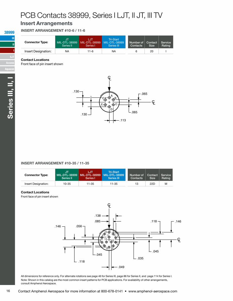
INSERT ARRANGEMENT #10-6 / 11-6
Connector Type:JT
MIL-DTL-38999 Series II
LJT MIL-DTL-38999
Series I
Tri-Start MIL-DTL-38999
Series IIINumber of Contacts
Contact Size
Service Rating
Insert Designation: NA 11-6 NA 6 20 I
Contact LocationsFront face of pin insert shown
All dimensions for reference only. For alternate rotations see page 46 for Series III, page 86 for Series II, and page 114 for Series I.Note: Shown in this catalog are the most common insert patterns for PCB applications. For availability of other arrangements, consult Amphenol Aerospace.
AB
C
D
E
F
.065
.113
.130
.065.130
INSERT ARRANGEMENT #10-35 / 11-35
Connector Type:JT
MIL-DTL-38999 Series II
LJT MIL-DTL-38999
Series I
Tri-Start MIL-DTL-38999
Series IIINumber of Contacts
Contact Size
Service Rating
Insert Designation: 10-35 11-35 11-35 13 22D M
Contact LocationsFront face of pin insert shown
PCB Contacts 38999, Series I LJT, II JT, III TV Insert Arrangements
16 Contact Amphenol Aerospace for more information at 800-678-0141 • www.amphenol-aerospace.com
38999
Ser
ies
III, I
I, I
III
SJT
I
II
Access
Aquacon

B
.094
.058
.111
AC
INSERT ARRANGEMENT #12-3 / 13-3
Connector Type:JT
MIL-DTL-38999 Series II
LJT MIL-DTL-38999
Series I
Tri-Start MIL-DTL-38999
Series III
Insert Designation: 12-3 13-3 NA
Contact LocationsFront face of pin insert shown
All dimensions for reference only. For alternate rotations see page 46 for Series III, page 86 for Series II, and page 114 for Series I.Note: Shown in this catalog are the most common insert patterns for PCB applications. For availability of other arrangements, consult Amphenol Aerospace.
11
.030
.026
.088.107
.158
.197
.203
.093
.120
.075
.045
.117
.126
.182
21
1
INSERT ARRANGEMENT #12-35 / 13-35
Connector Type:JT
MIL-DTL-38999 Series II
LJT MIL-DTL-38999
Series I
Tri-Start MIL-DTL-38999
Series III
Insert Designation: 12-35 13-35 13-35
Contact LocationsFront face of pin insert shown
Number of Contacts
Contact Size
Service Rating
22 22D M
Number of Contacts
Contact Size
Service Rating
3 16 II
PCB Contacts 38999, Series I LJT, II JT, III TV Insert Arrangements
17Contact Amphenol Aerospace for more information at 800-678-0141 • www.amphenol-aerospace.com
38999
Series III, II, I
III
SJT
I
II
Access
Aquacon

UT
S R
P
NM
L
K
J
H
G F E
D
A
B
C
.113
.225
.252.113
.260
.065
.130
.195.195
.130
.065
.260
INSERT ARRANGEMENT #14-18 / 15-18
Connector Type:JT
MIL-DTL-38999 Series II
LJT MIL-DTL-38999
Series I
Tri-Start MIL-DTL-38999
Series IIINumber of Contacts
Contact Size
Service Rating
Insert Designation: 14-18 15-18 15-18 18 20 I
Contact LocationsFront face of pin insert shown
All dimensions for reference only. For alternate rotations see page 46 for Series III, page 86 for Series II, and page 114 for Series I.Note: Shown in this catalog are the most common insert patterns for PCB applications. For availability of other arrangements, consult Amphenol Aerospace.
.065
C
BA
E
D
FG
J
H
U
T
L
K
N
M
V R
S
.225
.225
.065
.113
.113
.195
.260.195
.260
.130 .130
INSERT ARRANGEMENT #14-19 / 15-19
Connector Type:JT
MIL-DTL-38999 Series II
LJT MIL-DTL-38999
Series I
Tri-Start MIL-DTL-38999
Series IIINumber of Contacts
Contact Size
Service Rating
Insert Designation: 14-19 15-19 15-19 19 20 I
Contact LocationsFront face of pin insert shown
PCB Contacts 38999, Series I LJT, II JT, III TV Insert Arrangements
18 Contact Amphenol Aerospace for more information at 800-678-0141 • www.amphenol-aerospace.com
38999
Ser
ies
III, I
I, I
III
SJT
I
II
Access
Aquacon

Contact Hole Locations
Contact Number
Location
X Axis Y Axis
R –.131 +.293
S –.070 +.177
T +.070 +.177
U +.175 +.094
V +.178 –.036
W +.119 –.151
X .000 –.203
Y –.119 –.151
Z –.178 –.036
a –.175 +.094
b .000 +.065
c .000 –.065
F
E
AB
G
C
D
HJKL
M
N
P
RTS
U
V
WX
Y
Z
a b
c
Contact Hole Locations
Contact Number
Location
X Axis Y Axis
1 +.045 +.262
2 +.123 +.217
3 +.211 +.160
4 +.254 +.080
5 +.266 –.010
6 +.247 –.098
7 +.200 –.175
8 +.130 –.232
9 +.045 –.262
10 –.045 –.262
11 –.130 –.232
12 –.200 –.175
13 –.247 –.098
14 –.266 –.010
15 –.254 +.080
16 –.211 +.160
17 –.123 +.217
18 –.045 +.262
INSERT ARRANGEMENT #14-35 / 15-35
Connector Type:JT
MIL-DTL-38999 Series II
LJT MIL-DTL-38999
Series I
Tri-Start MIL-DTL-38999
Series IIINumber of Contacts
Contact Size
Service Rating
Insert Designation: 14-35 15-35 15-35 37 22D M
Contact LocationsFront face of pin insert shown
1
2131
11
All dimensions for reference only. For alternate rotations see page 46 for Series III, page 86 for Series II, and page 114 for Series I.Note: Shown in this catalog are the most common insert patterns for PCB applications. For availability of other arrangements, consult Amphenol Aerospace.
INSERT ARRANGEMENT #16-26 / 17-26
Connector Type:JT
MIL-DTL-38999 Series II
LJT MIL-DTL-38999
Series I
Tri-Start MIL-DTL-38999
Series IIINumber of Contacts
Contact Size
Service Rating
Insert Designation: NA 17-26 17-26 26 20 I
Contact LocationsFront face of pin insert shown
Contact Hole Locations
Contact Number
Location
X Axis Y Axis
A .000 +.321
B +.131 +.293
C +.239 +.214
D +.305 +.099
E +.319 –.034
F +.278 –.161
G +.189 –.260
H +.067 –.314
J –.067 –.314
K –.189 –.260
L –.278 –.161
M –.319 –.034
N –.305 +.099
P –.239 +.214
PCB Contacts 38999, Series I LJT, II JT, III TV Insert Arrangements
Contact Hole Locations
Contact Number
Location
X Axis Y Axis
19 +.045 +.172
20 +.123 +.119
21 +.170 +.040
22 +.170 –.050
23 +.123 –.127
24 +.045 –.172
25 –.045 –.172
26 –.123 –.127
27 –.170 –.050
28 –.170 +.040
29 –.123 +.119
30 –.045 +.172
31 +.045 +.074
32 +.090 –.004
33 +.045 –.082
34 –.045 –.082
35 –.090 –.004
36 –.045 +.074
37 .000 –.004
19Contact Amphenol Aerospace for more information at 800-678-0141 • www.amphenol-aerospace.com
38999
Series III, II, I
III
SJT
I
II
Access
Aquacon

All dimensions for reference only. For alternate rotations see page 46 for Series III, page 86 for Series II, and page 114 for Series I.Note: Shown in this catalog are the most common insert patterns for PCB applications. For availability of other arrangements, consult Amphenol Aerospace.
INSERT ARRANGEMENT #16-35 / 17-35
Connector Type:JT
MIL-DTL-38999 Series II
LJT MIL-DTL-38999
Series I
Tri-Start MIL-DTL-38999
Series IIINumber of Contacts
Contact Size
Service Rating
Insert Designation: 16-35 17-35 17-35 55 22D M
Contact LocationsFront face of pin insert shown Contact Hole Locations
Contact Number
LocationX Axis Y Axis
28 .000 –.004
29 .000 –.094
30 .000 –.184
31 .000 –.274
32 +.089 +.316
33 +.078 +.221
34 +.078 +.131
35 +.078 +.041
36 +.078 –.049
37 +.078 –.139
38 +.078 –.229
39 +.078 –.319
40 +.172 +.279
41 +.156 +.176
42 +.156 +.086
43 +.156 –.004
44 +.156 –.094
45 +.156 –.184
46 +.156 –.274
47 +.242 +.221
48 +.234 +.131
49 +.234 +.041
50 +.234 –.049
51 +.234 –.139
52 +.234 –.229
53 +.312 +.086
54 +.312 –.004
55 +.312 –.094
1710
4
1
39
1624 31
25 32
39
40
46
47
52
53
55
Contact Hole Locations
Contact Number
LocationX Axis Y Axis
1 –.312 +.086
2 –.312 –.004
3 –.312 –.094
4 –.242 +.221
5 –.234 +.131
6 –.234 +.041
7 –.234 –.049
8 –.234 –.139
9 –.234 –.229
10 –.172 +.279
11 –.156 +.176
12 –.156 +.086
13 –.156 –.004
14 –.156 –.094
15 –.156 –.184
16 –.156 –.274
17 –.089 +.316
18 –.078 +.221
19 –.078 +.131
20 –.078 +.041
21 –.078 –.049
22 –.078 –.139
23 –.078 –.229
24 –.078 –.319
25 .000 +.329
26 .000 +.176
27 .000 +.086
PCB Contacts 38999, Series I LJT, II JT, III TV Insert Arrangements
20 Contact Amphenol Aerospace for more information at 800-678-0141 • www.amphenol-aerospace.com
38999
Ser
ies
III, I
I, I
III
SJT
I
II
Access
Aquacon

L
K
J
H
G
F
E
D
A
B
C
.105
.132
.092
.053
.179
.275
.215.281
.260
.105
.250
INSERT ARRANGEMENT #18-11 / 19-11
Connector Type:JT
MIL-DTL-38999 Series II
LJT MIL-DTL-38999
Series INumber of Contacts
Contact Size
Service Rating
Insert Designation: 18-11 19-11 11 16 II
Contact LocationsFront face of pin insert shown
UT
S
R
P
N
g
f
M
LK
JH
G
F
E
D
h
AB
C
ab
c
e
d
V
W
X
YZ
j
INSERT ARRANGEMENT #18-32 / 19-32
Connector Type:JT
MIL-DTL-38999 Series II
LJT MIL-DTL-38999
Series I
Tri-Start MIL-DTL-38999
Series IIINumber of Contacts
Contact Size
Service Rating
Insert Designation: 18-32 19-32 19-32 32 20 I
Contact LocationsFront face of pin insert shown
Contact Hole Locations
Contact Letter
LocationX Axis Y Axis
A +.066 +.353
B +.189 +.305
C +.286 +.217
D +.345 +.098
E +.357 –.033
F +.321 –.160
G +.242 –.265
H +.130 –.335
J .000 –.359
K –.130 –.335
L –.242 –.265
M –.321 –.160
N –.357 –.033
P –.345 +.098
R –.286 +.217
S –.189 +.305
Contact Hole Locations
Contact Letter
LocationX Axis Y Axis
T –.066 +.353
U .000 +.230
V +.124 +.193
W +.209 +.095
X +.228 –.033
Y +.174 –.151
Z +.065 –.221
a –.065 –.221
b –.174 –.151
c –.228 –.033
d –.209 +.095
e –.124 +.193
f .000 +.096
g +.096 .000
h .000 –.096
j –.096 .000
All dimensions for reference only. For alternate rotations see page 46 for Series III, page 86 for Series II, and page 114 for Series I.Note: Shown in this catalog are the most common insert patterns for PCB applications. For availability of other arrangements, consult Amphenol Aerospace.
PCB Contacts 38999, Series I LJT, II JT, III TV Insert Arrangements
21Contact Amphenol Aerospace for more information at 800-678-0141 • www.amphenol-aerospace.com
38999
Series III, II, I
III
SJT
I
II
Access
Aquacon

1
.357
.279
.201
.123
.045
.045
.090
.135
.180
.225
.270
.315.360
410
1725 34
4351
58
64
66
6357
5042332416
9
3
INSERT ARRANGEMENT #18-35 / 19-35
Connector Type:JT
MIL-DTL-38999 Series II
LJT MIL-DTL-38999
Series I
Tri-Start MIL-DTL-38999
Series IIINumber of Contacts
Contact Size
Service Rating
Insert Designation: 18-35 19-35 19-35 66 22D M
Contact LocationsFront face of pin insert shown
A
B
C
D
S
T
E
FU
V
G
H
W
J
c
b
K
X
d
aP
R
L
M Y
ZN
.275
.225
.125
.400
.150
.275
.300
.200
.050
.025
.100
.150
.250
.375.150
.250
.400
.225
.100
.375 .400
INSERT ARRANGEMENT #20-27 / 21-27
Connector Type:JT
MIL-DTL-38999 Series II
LJT MIL-DTL-38999
Series I
Tri-Start MIL-DTL-38999
Series IIINumber of Contacts
Contact Size
Service Rating
Insert Designation: 20-27 21-27 NA 27 20 I
Contact LocationsFront face of pin insert shown
All dimensions for reference only. For alternate rotations see page 46 for Series III, page 86 for Series II, and page 114 for Series I.Note: Shown in this catalog are the most common insert patterns for PCB applications. For availability of other arrangements, consult Amphenol.
PCB Contacts 38999, Series I LJT, II JT, III TV Insert Arrangements
22 Contact Amphenol Aerospace for more information at 800-678-0141 • www.amphenol-aerospace.com
38999
Ser
ies
III, I
I, I
III
SJT
I
II
Access
Aquacon

INSERT ARRANGEMENT #20-35 / 21-35
Connector Type:JT
MIL-DTL-38999 Series II
LJT MIL-DTL-38999
Series I
Tri-Start MIL-DTL-38999
Series IIINumber of Contacts
Contact Size
Service Rating
Insert Designation: 20-35 21-35 21-35 79 22D M
Contact LocationsFront face of pin insert shown
Contact Hole Locations
Contact Number
Location
X Axis Y Axis
1 +.053 +.426
2 +.146 +.404
3 +.232 +.362
4 +.306 +.302
5 +.365 +.227
6 +.406 +.141
7 +.427 +.048
8 +.427 –.048
Contact Hole Locations
Contact Number
Location
X Axis Y Axis
9 +.406 –.141
10 +.365 –.227
11 +.306 –.302
12 +.232 –.362
13 +.146 –.404
14 +.053 –.426
15 –.053 –.426
16 –.146 –.404
17 –.232 –.362
18 –.306 –.302
19 –.365 –.227
20 –.406 –.141
21 –.427 –.048
22 –.427 +.048
23 –.406 +.141
24 –.365 +.227
25 –.306 +.302
26 –.232 +.362
27 –.146 +.404
28 –.053 +.426
29 .000 +.323
30 +.098 +.322
31 +.184 +.280
32 +.258 +.220
33 +.311 +.141
34 +.332 +.048
35 +.332 –.048
36 +.311 –.141
37 +.258 –.220
38 +.184 –.280
39 +.098 –.322
40 .000 –.347
41 –.098 –.322
42 –.184 –.280
Contact Hole Locations
Contact Number
Location
X Axis Y Axis
43 –.258 –.220
44 –.311 –.141
45 –.332 –.048
46 –.332 +.048
47 –.311 +.141
48 –.258 +.220
49 –.184 +.280
50 –.098 +.322
51 –.048 +.241
52 +.048 +.241
53 +.134 +.199
54 +.208 +.139
55 +.237 +.048
56 +.237 –.048
57 +.208 –.139
58 +.134 –.199
59 +.048 –.241
60 –.048 –.241
61 –.134 –.199
62 –.208 –.139
63 –.237 –.048
64 –.237 +.048
65 –.208 +.139
66 –.134 +.199
67 –.048 +.146
68 +.048 +.146
69 +.125 +.090
70 +.155 .000
71 +.125 –.090
72 +.048 –.146
73 –.048 –.146
74 –.125 –.090
75 –.155 .000
76 –.125 +.090
77 .000 +.053
78 +.048 –.029
79 –.048 –.029
1
31
79
61
41
21
11
71
51
All dimensions for reference only. For alternate rotations see page 46 for Series III, page 86 for Series II, and page 114 for Series I.Note: Shown in this catalog are the most common insert patterns for PCB applications. For availability of other arrangements, consult Amphenol Aerospace.
PCB Contacts 38999, Series I LJT, II JT, III TV Insert Arrangements
23Contact Amphenol Aerospace for more information at 800-678-0141 • www.amphenol-aerospace.com
38999
Series III, II, I
III
SJT
I
II
Access
Aquacon

U
T
S
R
P
N
g
f
ML K
JH
G
F
E
D
sh
ij
VW A
kY
BC
mZ
ar
n
t
q p
b
c
e d
X
.300 DIA.
.567 DIA.
.835 DIA.
INSERT ARRANGEMENT #20-41 / 21-41
Connector Type:JT
MIL-DTL-38999 Series II
LJT MIL-DTL-38999
Series I
Tri-Start MIL-DTL-38999
Series IIINumber of Contacts
Contact Size
Service Rating
Insert Designation: 20-41 21-41 21-41 41 20 I
Contact LocationsFront face of pin insert shown
All dimensions for reference only. For alternate rotations see page 46 for Series III, page 86 for Series II, and page 114 for Series I.Note: Shown in this catalog are the most common insert patterns for PCB applications. For availability of other arrangements, consult Amphenol Aerospace.
PCB Contacts 38999, Series I LJT, II JT, III TV Insert Arrangements
24 Contact Amphenol Aerospace for more information at 800-678-0141 • www.amphenol-aerospace.com
38999
Ser
ies
III, I
I, I
III
SJT
I
II
Access
Aquacon

INSERT ARRANGEMENT #22-35 / 23-35
Connector Type:JT
MIL-DTL-38999 Series II
LJT MIL-DTL-38999
Series I
Tri-Start MIL-DTL-38999
Series IIINumber of Contacts
Contact Size
Service Rating
Insert Designation: 22-35 23-35 23-35 100 22D M
Contact LocationsFront face of pin insert shown
Contact Hole Locations
Contact Number
LocationX Axis Y Axis
1 –.428 +.241
2 –.467 +.154
3 –.488 +.061
4 –.415 .000
5 –.488 –.061
6 –.428 –.142
7 –.428 –.237
8 –.332 +.333
9 –.332 +.238
10 –.332 +.143
11 –.332 +.048
12 –.332 –.047
13 –.332 –.142
14 –.332 –.237
15 –.332 –.332
16 –.249 +.380
17 –.249 +.285
18 –.249 +.190
19 –.249 +.095
Contact Hole Locations
Contact Number
LocationX Axis Y Axis
20 –.249 .000
21 –.249 –.095
22 –.249 –.190
23 –.249 –.285
24 –.249 –.380
25 –.166 +.428
26 –.166 +.333
27 –.166 +.238
28 –.166 +.143
29 –.166 +.048
30 –.166 –.047
31 –.166 –.142
32 –.166 –.237
33 –.166 –.332
34 –.166 –.427
35 –.083 +.475
36 –.083 +.380
37 –.083 +.285
38 –.083 +.190
39 –.083 +.095
40 –.083 .000
41 –.083 –.095
42 –.083 –.190
43 –.083 –.285
44 –.083 –.380
45 –.083 –.475
46 .000 +.428
47 .000 +.333
48 .000 +.238
49 .000 +.143
50 .000 +.048
51 .000 –.047
52 .000 –.142
53 .000 –.237
54 .000 –.332
55 .000 –.427
56 +.083 +.475
57 +.083 +.380
58 +.083 +.285
59 +.083 +.190
Contact Hole Locations
Contact Number
LocationX Axis Y Axis
60 +.083 +.095
61 +.083 .000
62 +.083 –.095
63 +.083 –.190
64 +.083 –.285
65 +.083 –.380
66 +.083 –.475
67 +.166 +.428
68 +.166 +.333
69 +.166 +.238
70 +.166 +.143
71 +.166 +.048
72 +.166 –.047
73 +.166 –.142
74 +.166 –.237
75 +.166 –.332
76 +.166 –.427
77 +.249 +.380
78 +.249 +.285
79 +.249 +.190
80 +.249 +.095
81 +.249 .000
82 +.249 –.095
83 +.249 –.190
84 +.249 –.285
85 +.249 –.380
86 +.332 +.333
87 +.332 +.238
88 +.332 +.143
89 +.332 +.048
90 +.332 –.047
91 +.332 –.142
92 +.332 –.237
93 +.332 –.332
94 +.428 +.241
95 +.467 +.154
96 +.488 +.061
97 +.415 .000
98 +.488 –.061
99 +.428 –.142
100 +.428 –.237
95
9796
100
98
99
9385
76665 5
4 53 4
2 415
7
6
5
4
3
2
1
816
25 354 6
56 6777
86
94
All dimensions for reference only. For alternate rotations see page 46 for Series III, page 86 for Series II, and page 114 for Series I.Note: Shown in this catalog are the most common insert patterns for PCB applications. For availability of other arrangements, consult Amphenol Aerospace.
PCB Contacts 38999, Series I LJT, II JT, III TV Insert Arrangements
25Contact Amphenol Aerospace for more information at 800-678-0141 • www.amphenol-aerospace.com
38999
Series III, II, I
III
SJT
I
II
Access
Aquacon

B
Z
D
C
E
F
G
YXW
p
V
UT
nSm
AA qr
sa
b
DDtEE
uc
Hd
vw
eJK
Lf
gM
FFy
CCBB
GGz
iHH
xh
N
jP
R k
A.260
.225
.112
.336
.065
.450
.195
.455
.325
.130
.390
INSERT ARRANGEMENT #22-55 / 23-55
Connector Type:JT
MIL-DTL-38999 Series II
LJT MIL-DTL-38999
Series I
Tri-Start MIL-DTL-38999
Series III
Number of Contacts
Contact Size
Service Rating
Insert Designation: 22-55 23-55 23-55 55 20 I
Contact LocationsFront face of pin insert shown
A
.474
.158.316
.091
.273
.455
.182
.364
B
C
D
E
FG
H
J
K
YZ
Xe
d
T
WV
U
S
c
g
f
L
M
NP
Qb
a
R
INSERT ARRANGEMENT #24-31 / 25-31
Connector Type:JT
MIL-DTL-38999 Series II
LJT MIL-DTL-38999
Series I
Tri-Start MIL-DTL-38999
Series IIINumber of Contacts
Contact Size
Service Rating
Insert Designation: 24-31 NA NA 31 16 I
Contact LocationsFront face of pin insert shown
All dimensions for reference only. For alternate rotations see page 46 for Series III, page 86 for Series II, and page 114 for Series I.Note: Shown in this catalog are the most common insert patterns for PCB applications. For availability of other arrangements, consult Amphenol Aerospace.
PCB Contacts 38999, Series I LJT, II JT, III TV Insert Arrangements
26 Contact Amphenol Aerospace for more information at 800-678-0141 • www.amphenol-aerospace.com
38999
Ser
ies
III, I
I, I
III
SJT
I
II
Access
Aquacon

1
8 1525 36
4859
7182
94105115
125
121
114104
9381705847
3524
14
4
7
INSERT ARRANGEMENT #24-35 / 25-35
Connector Type:JT
MIL-DTL-38999 Series II
LJT MIL-DTL-38999
Series I
Tri-Start MIL-DTL-38999
Series IIINumber of Contacts
Contact Size
Service Rating
Insert Designation: 24-35 25-35 25-35 128 22D M
Contact LocationsFront face of pin insert shown
Contact Hole Locations
Contact Number
LocationX Axis Y Axis
1 –.479 +.2792 –.520 +.1903 –.546 +.0954 –.555 .0005 –.546 –.0956 –.520 –.1907 –.479 –.2798 –.424 +.3579 –.415 +.19010 –.415 +.09511 –.415 .00012 –.415 –.09513 –.415 –.19014 –.424 –.35715 –.332 +.44416 –.332 +.33217 –.332 +.23718 –.332 +.14219 –.332 +.04720 –.332 –.04721 –.332 –.14222 –.332 –.23723 –.332 –.33224 –.332 –.42725 –.249 +.49626 –.249 +.38027 –.249 +.28528 –.249 +.190
Contact Hole Locations
Contact Number
LocationX Axis Y Axis
29 –.249 +.09530 –.249 .00031 –.249 –.09532 –.249 –.19033 –.249 –.28534 –.249 –.38035 –.249 –.47536 –.160 +.53137 –.166 +.42738 –.166 +.33239 –.166 +.23740 –.166 +.14241 –.166 +.04742 –.166 –.04743 –.166 –.14244 –.166 –.23745 –.166 –.33246 –.166 –.42747 –.166 –.52248 –.083 +.47549 –.083 +.38050 –.083 +.28551 –.083 +.19052 –.083 +.09553 –.083 .00054 –.083 –.09555 –.083 –.19056 –.083 –.28557 –.083 –.38058 –.083 –.47559 .000 +.52260 .000 +.42761 .000 +.33262 .000 +.23763 .000 +.14264 .000 +.04765 .000 –.04766 .000 –.14267 .000 –.23768 .000 –.33269 .000 –.42770 .000 –.55571 +.083 +.47572 +.083 +.38073 +.083 +.28574 +.083 +.19075 +.083 +.09576 +.083 .00077 +.083 –.09578 +.083 –.190
Contact Hole Locations
Contact Number
LocationX Axis Y Axis
79 +.083 –.28580 +.083 –.38081 +.083 –.47582 +.160 +.53183 +.166 +.42784 +.166 +.33285 +.166 +.23786 +.166 +.14287 +.166 +.04788 +.166 –.04789 +.166 –.14290 +.166 –.23791 +.166 –.33292 +.166 –.42793 +.166 –.52294 +.249 +.49695 +.249 +.38096 +.249 +.28597 +.249 +.19098 +.249 +.09599 +.249 .000100 +.249 –.095101 +.249 –.190102 +.249 –.285103 +.249 –.380104 +.249 –.475105 +.332 +.444106 +.332 +.332107 +.332 +.237108 +.332 +.142109 +.332 +.047110 +.332 –.047111 +.332 –.142112 +.332 –.237113 +.332 –.332114 +.332 –.427115 +.424 +.357116 +.415 +.190117 +.415 +.095118 +.415 .000119 +.415 –.095120 +.415 –.190121 +.424 –.357122 +.479 +.279123 +.520 +.190124 +.546 +.095125 +.555 .000126 +.546 –.095127 +.520 –.190128 +.479 –.279
All dimensions for reference only. For alternate rotations see page 46 for Series III, page 86 for Series II, and page 114 for Series I.Note: Shown in this catalog are the most common insert patterns for PCB applications. For availability of other arrangements, consult Amphenol Aerospace.
PCB Contacts 38999, Series I LJT, II JT, III TV Insert Arrangements
27Contact Amphenol Aerospace for more information at 800-678-0141 • www.amphenol-aerospace.com
38999
Series III, II, I
III
SJT
I
II
Access
Aquacon

INSERT ARRANGEMENT #24-61 / 25-61
Connector Type:JT
MIL-DTL-38999 Series II
LJT MIL-DTL-38999
Series I
Tri-Start MIL-DTL-38999
Series IIINumber of Contacts
Contact Size
Service Rating
Insert Designation: 24-61 25-61 25-61 61 20 I
Contact LocationsFront face of pin insert shown
A
E
B
C
D
F
G
H
J
K
V
LMN
pR
S
T
U
XY
Za b
W
c
d
e
jkm
f
h
i
r
gq
s
t
uv
w
x
y
z
AABBCC
DD
EE
FF
GG HH
MM
NN JJPP
KK
LL
P
All dimensions for reference only.For alternate rotations see page 46 for Series III, page 86 for Series II, and page 114 for Series I.Note: Shown in this catalog are the most common insert patterns for PCB applications. For availability of other arrangements, consult Amphenol Aerospace.
Contact Hole Locations
Contact Number
Location
X Axis Y Axis
A +.196 +.500
B +.314 +.435
C +.413 +.343
D +.485 +.230
E +.527 +.101
F +.536 –.030
G +.511 –.164
H +.454 –.287
J +.368 –.391
K +.259 –.470
L +.134 –.519
M .000 –.537
N –.134 –.519
P –.259 –.470
R –.368 –.391
S –.454 –.287
T –.511 –.164
U –.536 –.030
V –.527 +.101
W –.485 +.230
X –.413 +.343
Y –.314 +.435
Z –.196 +.500
a –.068 +.454
b +.068 +.454
c +.173 +.363
d +.285 +.283
e +.362 +.175
f +.399 +.046
g +.392 –.088
Contact Hole Locations
Contact Number
Location
X Axis Y Axis
h +.341 –.213
i +.251 –.314
j +.133 –.379
k .000 –.402
m –.133 –.379
n –.251 –.314
p –.341 –.213
q –.392 –.088
r –.399 +.046
s –.362 +.175
t –.285 +.283
u –.173 +.363
v .000 +.338
w +.147 +.223
x +.237 +.122
y +.267 –.010
z +.228 –.139
AA +.131 –.233
BB .000 –.267
CC –.131 –.233
DD –.228 –.139
EE –.267 –.010
FF –.237 +.122
GG –.147 +.223
HH .000 +.200
JJ +.105 +.094
KK +.135 –.041
LL .000 –.132
MM –.135 –.041
NN –.105 +.094
PP .000 .000
28 Contact Amphenol Aerospace for more information at 800-678-0141 • www.amphenol-aerospace.com
38999
Ser
ies
III, I
I, I
III
SJT
I
II
Access
Aquacon
PCB Contacts 38999, Series I LJT, II JT, III TV Insert Arrangements