MIL-DTL-28689C Containers, Shipping and Storage, Steel ...
26
I I EEEmIm MIL-DTL-28689C Januaw 17.1997 SUPERSEDING ~C-28689B(YD) 21 May 1993 DETAIL SPECIFICATION CONTAINERS, SHIPPING AND STORAGE, STEEL WALL (’WITHAND WITHOUTcABrmTRY) This specification is approved for use by ztll Departments and Agencies of the Department of Defense. 1. SCOPE 1.1 Scope. This specification covers equipment containers used to store and ship items listed in Naval Construction Force tables of allowance. The containers are of two sizes and either empty for bulk loading of materials or configured with cabinetry to simplifj locating parts and equipment for distribution. 1.2 Classification. 1.2.1 Containers. Containers covered by this specification shall be classified by the following type and styles (see 6.2): Type I - 8-foot by 8-foot (2 438 mmby2438 mm) by 20-foot (6 096 mm) wntainer (ISO Series “lC”). Type II - 8-foot by 8-foot (2 438 mmby2438 mm) by 6-foot 5.5-inch (1 968 mm) container (TRICON). Style 1 - Empty container, for loading of large bulk material. Style 2 - Container with cabi.netry installed. Beneficial comments, recommendations, additions, deletions, clarifications, etc. and any data which may improve this document should be sent to: Commanding Officer (Code 1581), Naval Construction Battalion Center, Port Hueneme, CA 93043-4301, by using the Standardization Document Improvement Proposal (DD Form 1426) appearing at the end of this document or by letter. AMSC N/A FSC 8145 DISTRIBUTION STATEMENT A. Approved for public release; distribution is urdhnited. Downloaded from http://www.everyspec.com
Transcript of MIL-DTL-28689C Containers, Shipping and Storage, Steel ...

I
I
EEEmImMIL-DTL-28689CJanuaw 17.1997SUPERSEDING~C-28689B(YD)21 May 1993
DETAIL SPECIFICATION
CONTAINERS, SHIPPING AND STORAGE, STEEL WALL(’WITHAND WITHOUTcABrmTRY)
This specification is approved for use by ztll Departments and Agencies of theDepartment of Defense.
1. SCOPE
1.1 Scope. This specification covers equipment containers used to store and ship items listed inNaval Construction Force tables of allowance. The containers are of two sizes and either emptyfor bulk loading of materials or configured with cabinetry to simplifj locating parts and equipmentfor distribution.
1.2 Classification.
1.2.1 Containers. Containers covered by this specification shall be classified by the followingtype and styles (see 6.2):
Type I - 8-foot by 8-foot (2 438 mmby2438 mm) by 20-foot (6 096 mm) wntainer(ISO Series “lC”).
Type II - 8-foot by 8-foot (2 438 mmby2438 mm) by 6-foot 5.5-inch (1 968 mm)container (TRICON).
Style 1 - Empty container, for loading of large bulk material.Style 2 - Container with cabi.netryinstalled.
Beneficial comments, recommendations, additions, deletions, clarifications, etc. and any datawhich may improve this document should be sent to: Commanding Officer (Code 1581), NavalConstruction Battalion Center, Port Hueneme, CA 93043-4301, by using the StandardizationDocument Improvement Proposal (DD Form 1426) appearing at the end of this document or byletter.
AMSC N/A FSC 8145
DISTRIBUTION STATEMENT A. Approved for public release; distribution is urdhnited.
Downloaded from http://www.everyspec.com

MJL-DTL-28689C
1.2.2 Cabinet~. Cabinetry used in style 2 containers shall be of the configuration shown in thedrawings (see 3.1.2).
2. APPLICABLE DOCUMENTS
2.1 General. The documents listed in this section are specified in sections 3 and 4 of thisspecification. This section does not include documents cited in other sections of this specificationor remrnmended for additional itiormation or as examples. While every effort has been made toensure the completeness of this list, document users are cautioned that they must meet allspecified requirements documents cited in sections 3 and 4 of this specification, whether or notthey are listed.
2.2 Government documents.
2.2.1 Specifications and standards. The following specifications and standards forma part of thisdocument to the extent specified herein. Unless otherwise specified, the issues of thesedocuments are those listed in the issue of the Department of Defense Index of Specifications andStandards (DoDISS) and supplement thereto, cited i.nthe solicitation (see 6.2).
SPECIFICATIONS
FEDERAL
FF-S-2738 - Seals, Antipilferage.
MILITARY
A-A-50271 - Plate, Identification.MIL-P-2444U20 - Paint, Epoxy-Polyamide, Green Primer, Formula 150, Type 1.ML-P-2444 1/22 - Paint, Epoxy-Polyamide, Topcoat, White, Formula 152, Type 1.ML-C-46168 - Coating, Aliphatic Polyurethane, Chemical Agent Resistant.MIL-P-53022 - Primer, Epoxy Coating, Corrosion Inhibiting, Lead and Chromate
Free.MIL-C-53039 - Coating, Mphatic Polyurethane, Single Component, Chemical
Agent Resistant.MIL-C-53072 - Chemical Agent Resistant Coating (CARC) System Application
Procedures and QuaMy Control Inspection.
STANDARDS
FEDEIL%L
FED-STD-595 - Colors Used in Government Procurement.
Downloaded from http://www.everyspec.com

MIL-DTL-28689C
(Unless otherwise indicated, copies of the above specifications and standards are available fromthe Standardization Documents Order Desk Bldg. 4D, 700 Robbins Avenue, Philadelphi~ PA19111-5094.)
2.2.2 Other Government r.mblications. The following other Government publications forma partof this document to the extent specified herein. Unless otherwise specified, the issues are thosecited in the solicitation.
DEPARTMENT OF TIL4NSPORTATION @oT)
Code of Federal Regulations (CFR), Title 49, Part 450- Safety Approval of Cargo Containers.Code of Federal Re&lations (CFR), Title 49, Part 451- Testing ~-d Approval of Containers.
(Application for copies should be addressed to the Superintendent of Documents, U.S.Government Printing Office, Washington, DC 20402.)
DRAWINGS
NAVAL FACILITIES ENGINEERING COMMAND (NAVFAC)
6028532- NCF Container Wall Configurations - 2A/2B.6028533- NCF Container Wall Configurations - 3A/3B.6028534- NCF Container Wall Configurations - 4A/4B.6028535- NCF Container Wall Configurations - 5A/5B.6028536- NCF Container Wall Configurations - DIA/DIB.6028537- NCF Container Wall Configurations - D2A/D2B.6028538- NCF Container Wall Configurations - D3C.6139128- Armo~, Air Det (TIUCON).6139129- Armory, Air Echelon (ISO Series “IC”).
(Copies of these drawings are available from Commanding Officer, Naval Construction BattalionCenter, Code 1581, 1000 23rd Avenue, Port Hueneme, CA 93043 -4301.)
2.3 Non-Government publications. The following other documents form a part of this documentto the extent specified herein. Unless othenvise specified, the issues of the documents which areDoD adopted are those listed in the issue of the DoDISS cited in the solicitation. Unlessotherwise specified, the issues of documents not listed in the DoDISS are the issues of thedocuments cited in the solicitation (see 6.2).
ASTM
ASTM B 633 - Electrodeposited Coatings of Zinc on Iron and Steel.ASTM B 650 - Electrodeposited Engineering Chromium Coatings on Ferrous Substrates.ASTM D 746 - Brittleness Temperature of Plastics and Elastomers by Impact.ASTM D 1640 - Drying, Curing, or Film Formation of Organic Coatings at Room Temperature.
3
Downloaded from http://www.everyspec.com

MIL-DTL-28689C
ASTMD3359 -Measuring Adhesion byTapeTest.ASTM D 4417 - Field Measurement of Surface Profile of Blast Cleaned Steel,
(Applications for copies should be addressed to the ASTM, 100 Barr Harbor Drive, WestConshohocke~ PA 19428-2959.)
AMERICAN WELDING SOCIETY (AWS)
AWS D1. 1- Structural Welding Code - Steel.
(Applications for copies should be addressed to the American Welding Society, 550 N.W.LeJeune Road, Miami, FL 33126.)
NATIONAL HARDWOOD LUMBER ASSOCIATION (NHLA)
Rules for the Measurement and Inspection of Hardwood and Cypress Lumber.
(Applications for copies should be addressed to the National Hardwood Lumber Associatio~I P.0~ Box 34518, Memphis, TN 38134,)I
INTERNATIONAL ORGANIZATION FOR STANDARDIZATION (1S0)
1s0 668 - Series 1 Freight Containers - Classificatio~ Dimensions and Ratings.1S0 1161 - Series 1 I?reight Containers - Comer Fittings.1S0 1496-1- Series 1 Freight Containers - Specification and Testing - Part 1: General Cargo
Containers for General Purposes.1S0 6346 - Freight Containers - Coding, Identification and Marking.
(Applications for copies should be addressed to the American National Standards Institute,11 West 42nd Street, New York NY 1,0036.)
STEEL STRUCTURES PAINTING COUNCIL (SSPC)
SSPC-SP 10 - Joint Surface Preparation Standard for Near-WWe Blast Cleaning.SSPC-PA 1 - Shop, Field, and Maintenance Painting.SSPC-PA 2 - Measurement of Dry Paint Thickness with Magnetic Gages.SSPC-VIS 1 - Visual Standard for Abrasive Blast Cleaned Steel.
(Applications for copies should be addressed to the Steel Structures Painting Council, 4516 HenryStreet, Suite 301, Pittsburg~ PA 15213-3728.)
2.4 Order of txecedence. IrI the event of a conflict between the text of this document and thereferences cited herein, the text of this document takes precedence. Nothing in this document,however, supersedes applicable laws and regulations unless a specific exemption has beenobtained.
4
Downloaded from http://www.everyspec.com

MIL-DTL-28689C
3. REQUIREMENTS
3.1 Descrirmion. Containers covered by this specification shall be of the type and style specifiedin the contract. The term “cabinet@’ as used in this specification, shall refer to cabinets withdrawers or shelves.
3.1.1 Containers. The containers shall be closed-van general-purpose freight containers, asdefined in 1S0 668. Three type II containers coupled end-to-end, using captive connectingcouplers described in 3.4.13, shall form an integral 20-foot (6 096 mm) module dimensionallyequivalent to the type I container. Each container shall have a current Convention for SafeContainers (CSC) certification issued by an “approved authori~ designated as such by theUnited States Coast Guard in accordance with 49 CFR 450, subpart B. CSC certification testsfor type It containers shall be performed on three coupled containers in the lC configuration.Definition of container term~nology and classification shall conform to 1S0 668.
3.1.2 Cabinets. The cabinets shall consist of a housing containing a combination of drawers orshelves in various configurations as shown in NAVFAC Drawings Nos. 6028532, 6028533,6028534, 6028535, 6028536, 6028537, 6028538, 6139128, and 6139129. Configuration numberidentified with an “A” suffix is installed on the right side of the container as viewed horn thecontainer entrance. A “B” suffix indicates the configuration mounted on the left side of thecontainer. The configuration with a “C” suflix is designed to be installed against the end wall of atype II container. Cabinet design shall make maximum use of available space inside containerwithin the constraints established by this specification. The cabinet~, excluding weapons storageracks, shall be provided by a single manufacturer to insure modularity and interchangeability ofparts.
3.2 .First article. The supplier shall fimish the number of containers and of the type, style, andconfiguration as specified in 6.2 for first article examination and test, to prove that his productionmethods will produce finished containers that comply with the requirements of this specification.Examination and test shall be those specified herein and shall be subjected to surveillance andapproval by the Government.
3.3 Materials. Materials used shall be free from defects which would adversely affect theperformance or maintainability of individual components or of the overall assembly. Materials notspecified herein shall be of the same quality used for the intended purpose in commercial practice.Unless otherwise specified herei~ all equipment, material, and articles incorporated in the workcovered by this specification are to be new and fabricated using materials produced fromrecovered materials to the maximum extent possible without jeopardizing the intended use. Theterm “recovered materials” means materials which have been collected or recovered born solidwaste and reprocessed to become a source of raw materials, as opposed to virgin raw materials.Unless otherwise specified, none of the above shall be interpreted to mean that the use of used orrebuilt products is allowed under this specification.
Downloaded from http://www.everyspec.com

MIL-.DTL-28689C
3.3.1 Dissimilar metals. Intimate contact of dissimilar metals which can be expected to causegalvanic corrosion shall be avoided. When such contact cannot be avoided, an interposinginsulating material shall be provided to minimize the corrosive effect.
3.4 Container construction. ANcontainers shall be new and unused. Each container shall beconstructed on a steel fi-amewith bottom crossmembers, steel corrugated walls, steel corrugatedroot metal doors, and 1S0 corner fittings at all comers. Containers shall be constructed so as tobe free of any recesses and voids in which contraband can be concealed or where moisture canaccumulate. No part of the container shall protrude beyond the outside sutiaces of the comerfittings. Caulking shall not be used on any interior or exterior container surface. Containers shallbe designed and constructed to withstand the static and dyntic loads induced by the testsspecified in 4.5. M containers shall be designed and constructed to be weatherproof Any waterleakage, either during the simulated rainfall test of 4.5.4 or during actual rain conditions, will beconsidered evidence that the container is not weatherproof.
3.4.1 Weight. Container weight limits shall be as given in table 1. Actual tare weight in pounds
(ibs) (Wograms (kg)) of style 2 containers shall be the sum of the weight of the empty containerplus the weight of installed cabinetry.
TABLE I. Container wei~ht limits.
Container Maximum Tare Weight Maximum GrossWithout Cabinetry Rating
Type I 5,000 lbs (2 268 kg) 44,800 Ibs (20 321 kg)Type II 2,700 Ibs (1 225 kg) 14,900 Ibs ( 6759 kg)
3.4.2 Dimensions. The minimum internal dimensions and actual external dimensions andtolerances shall be in accordance with 1S0 668, as modified in table H.
TABLE II. Dimensions.
Container Height (inches) (mm) Width (inches) (mm) Length (inches) (mm)Type I Interior 87(2 210) min. 91 3/4(2 230) min. 231 (5 867) min.
Exterior 96+ O,-3/16 96+ O,-3/16 238 1/2 + 0,-1/4(2 438+ O,-5) (2 438+ O,-5) (6 058+ O,-5)
Type II Interior 86 1/2 (2 197) min. 90 l/2(2 299) min. 73 (1 854) min.Exterior 96+ 0, -3/16 96+0,-3/16 77 1/2+ O,-3/ 16
(2 438 + O,-5) (2 438+ O,-5) (1 968+ O,-5)
3.4.3 Scuff boards. The interior of the front end wall, opposite the doors, of type 1, style 1containers shall have scuff boards installed. The scuff boards shall be nominal0.75-inch (19 mm) by 12-inch (305 mm) by length of the wall of class A vehicle grade apitongconforming to the requirements of the NHLA Rules for the Measurement and Inspection ofHardwood and Cypress Lumber or of comparable size and gage of galvanized steel beam guardrail. The lower edge of the scuff board shall be 2.5 + O.5-inch (63 * 13 mm) above the bottom
6
Downloaded from http://www.everyspec.com

MIL-DTL-28689C
frame rail. Fasteners shall be located at intervals adequate to hold the scuff boards securely inplace. Fasteners shall not penetrate the outside wall of the container. The scuff boards shall notbe installed until all interior material surfaces have been cleaned, and painted as specified in 3.8and 3.8.1.
3.4.4 .Floor construction. The floor shall be of solid hardwood boards. The boards shall runlongitudinally except that the width of the longitudinal edge boards maybe different, if required.When the widths of both longitudinal edge boards differ from the intermediate plank widt~ theyshall be of the same width as each other. The board edges shall be jointed by shiplapconstruction. The boards shall be attached to the crossmembers by means of not less than threefasteners per board, per crossmembers, for boards over 7 inches (178 mm) wide, and twofweners per board, per crossmembers, for boards less than 7 inches (1.78 mm) wide.Countersunk head fasteners, not less than 0.25-inch (6 mm) diameter, either of the self-tappingscrew type, or machine screw with self-locking nuts, shall be installed so that each head is Oto0.0625-inch (Oto 1.6 mm) below the board surface and at least 1-inch (25 mm) from the boardedge. The floor shall be installed to permit lateral variations in floorboard width due to swelling.
3.4.5 Understructure. Container bottom site rails and bottom end frame members shall notdeflect more than 0.25-inch (6 mm) below the bottom plane of the bottom comer fittings whenthe container is tested as specified in 4.5. Crossmembers shall not deflect below the bottom planeof the bottom comer fitting when the container is tested as specified in 4.5. All cross-membersshall be of the same configuration and strength and shall have a center-to-center distance of notgreater than 12 inches (305 mm), except where the 14-inch(356 mm) wide forldifi pockets arelocated on the type 1 containers.
3.4.5.1 Forklift Dockets. Each container shall have collared design forklift pockets. Type Icontainers shall have two sets of forklift pockets. The first set of forklifl pockets shall be not lessthan 14 inches (356 mm) wide by not less than 4.5 inches(114 mm) high; spacing for forkliftpockets shall be81*2inches(2057 *51 mm), center-to-center of the forklift pockets. Thesecond set of forklift pockets shall be not less than 12 inches (305 mm) wide by not less than4 inches (101 mm) high; spacing for forldft pockets shall be 35.5 + 2 inches (902+51 mm),center-to-center of the forklift pockets. Type II containers shall have lift entry from both sidesand from the closed end of the container; the forklift pockets shall be not less than 12 inches(305 mm) wide by not less than 4 inches (102 mm) high; spacing for forklift pockets shall be35.5 * 2 inches (902* 51 mm), center-to-center of the forldifi pockets. All fork.lifipockets shallbe in accordance with 1S0 1496-1, Annex C. Type I containers shall be clearly marked “USE8-FOOT TINES ONLY’ and “INNER FORKLIFT POCKETS ARE FOR HANDLINGUNLOADED CONTAINERS ONLY.” Letters shall be 2 inches (51 mm) high.
3.4.6 Roof construction. The roof shall be self-draining, and of corrugated construction. If roofbows are fastened to the roof sheet, they shall be bonded by a suitable bonding agent. In the caseof roof bows that are not fastened to the roof sheet, antichafing material shall be af%xedto theroof bows on the surfaces facing the roof sheets. The roof sheet roof rails, and upper end fhmemembers shall be not less than 0.25-inch (6 mm) below the top plane of the top comer fittings.
Downloaded from http://www.everyspec.com

MIL-DTL-28689C
3.4.7 Doors. Door openings shall conform to ISO 1496-1. Doors in type II containers shall behung in the nominal 6-foot 8-inch (2 032 mm) wide container frame to provide a clear interioropening of not less than 84 inches (2 134 mm) high and 70-3/4 inches (1 797 mm) wide. Fourheavy-duty pin hinges per door, equally spaced, recessed within the comer structure shall beprovided on each door allowing the door to fold back against the sides of the body. Steel hingesshall include nylatron bushings to permit smooth door operation. Means shall be provided to holdthe doors in the fill open position. Each door shall have two or more heavy-duty, hand operated,cam locking handles with anti-rack provisions. Handles shall be between 12 inches (305 mm) and18 inches (457 mm) above the bottom plane of the comer fittings. All locking device handlesshall be finished with provisions for padlocking and customs sealing.
3.4.7.1 Door gasket. The door weather seal gaskets shall be ethylene propylene with dienemonomer (EPDM) synthetic rubber extruded shape with flexible double type flanges. The EPDMmaterial must meet or exceed the low temperature brittleness test o.fASTM D 746 to -40 degrees “
Fahrenheit ~F) (-40 degrees Celsius ~C)), The gaskets shall be provided around the entireperiphery of each door, except for the vertical right side of the left hand door. The leil hand doorshall be designed to mate with the right hand door gasket. The right hand door shall open firstand close last. The major seal flange shall petiorm as an internal gasket on the frame. Both sealflanges shall be shaped to yield firmer seats with increasing positive external pressure. Thecorners of the gaskets shall be mitered at 45 degrees and heat bonded into one (1) continuoussection. Mechanical fasteners shall be used to attach the gasket material to the door. The doors,when closed, shall form a weatherproof seal. Door gaskets shall be black.
3.4.8 Comer fittings. Type I containers shall be constructed with top and bottom comer fittingsconforming to 1S0 1161. Bottom comer fittings conforming to 1S0 1161 will be installed onboth top and bottom comer fitting locations of Type II containers.
3.4.9 Antinilfera~e Provisions. I%nge-pins and screws, bolts, and other fasteners used forsecuring the hinges and closing devices to the container and for holdlng the essential parts of thesides, ends, and roof. Fasteners shall be tack welded or otherwise secured in such a manner as toprevent access to the interior of the container without leasing visible signs of tampering. Wheresuch welding destroys the protective coating on the items being welded or on other containerparts, the weld and surrounding area shall be thoroughly cleaned, treated, and painted inaccordance with 3.8. All locking device handles shall be fi.n-nishedwith provisions for padlockingand customs sealing.
3.4.10 Bulk load restraint svstem. A barrier type restraint system for bulk loaded material shallbe designed into the door frame of all containers. The system shall provide for positioning threehorizontal 2-inch by 6-inch (51 mm by 152 mm) beams at nominal 2 feet (610 mm), 4 feet(1 219 mm), and 6 feet (1 829 mm) above the floor. In style 2 containers, when there isinsufficient clearance between the cabinetry and the iiont comer post, the barrier restraint systemis not required.
3.4.11 Tie-down eves. Tie-down eyes shall be installed in the style 1 container and on the emptyor partially empty wall in the style 2 container. Tie-down eyes shall be welded to the interior of
8
Downloaded from http://www.everyspec.com
MCL-DTL-28689C
the container on the base frame and roof fiarne, set into the recess of wall corrugations. In type Icontainers, seven eyes shall be evenly spaced approximately 45 inches (1 143 mm) apart alongeach side wall base and roof hrne. One tie-down eye shall be mounted at the center of the endwall base fiarne; this arrangement shall be duplicated on the end wall roof frame. In type IIcontainers, five eyes shall be spaced approximately 24 inches (61,Omm) apart along each side walland one mounted at the center of the end wall. This arrangement applies to both the bottom andtop fhmes. All tie-down eyes shall be rated at not less than 4,000 pounds (1 814 kg).
3.4.12 Tie-down rods. Tie-down rods shall be 0.625-inch (16 mm) smooth rod. Each rod shallbe of one piece for the fbll length of the wall. Rods shall be welded horizontally to all the interiorwalls of style 1 containers and on the empty wall space, not covered by cabinetry in style 2containers. Rods shall be located at 6 * 0.25 inches (152+ 6 mm), 24 * 0.25 inches(610 + 6 mm),48*0.25inches(1219 + 6 mm), and 72 * 0.25 inches (1 829 * 6 mm), above thebase frame. On end walk which have scuff boards, the rods shall be welded at 24 + 0.25 inches(610 * 6 mm),48*0.25inches(1219 * 6 mm), and 72 + 0.25 inches (1 829 + 6 mm) above thebase fhme. Rebar is not allowed.
3.4.13 Captive connecting couolers. Each type II container shall be provided with three captiveconnecting couplers conforming to NSN 5410-01-363-7086. Suitable storage space for thesecouplers shall be provided in the container. Location of storage space shaUbe in such a mannerthat it will not interfere with drawer or cabinet door use with or without captive connectingcouplers installed.
3.4.14 Power sur)~lv cord Dort. Each container shall have a power supply cord port. The powersupply port shali be located approximately at the midpoint of the end wall, except in the TRICONarmory and D3C configurations. Port for the TR.ICON armory and D3C configurations shall belocated on right wall, looking into the container, approximately 24 inches (61Omm) below theheader and 24 inches (61Omm) from the comer post. Power supply cord port shall be located insuch a manner that it will not interfere with or be covered by the cabinets, rifle racks, or cabinetdoors. Power supply cord port shall consist of a 2-inch (51 mm) inside diameter pipe nipple,inserted into an appropriately sized hole through and welded to the crest of the corrugation of theend wall. The exterior pipe end shall not protrude beyond the container envelope. The interiorpipe end shall not protrude beyond highest point of corrugation on the interior of the wail, &internal feller plug shall be provided to make a weatherproof seal. The feller plug, when installed,shall not protrude beyond the tie-down rod. The plug shall also be capable of being installed orremoved without use of tools.
3.4.15 Container vents. All type I and type H containers shall have passive venting system. Theventing system shall dissipate condensed moisture within the container during field operations.The venting system shall be similar to commonly used venting systems in commercial 1S0containers. A vent cover shall be an integral part of the vent. The vents shall be capable of beingopened and closed from the outside without use of tools. Two vents shall be located in each sidewall, at opposite end of the containers. Vents shall be located as close to the top of the wall aspractical. The venting system shall not violate MO envelope requirements, nor shall the ventsprotrude into the interior beyond the protective tie-bar system. The vents, when ope~ shall not
9
Downloaded from http://www.everyspec.com

NUL-DTL-28689C
permit wind driven rain or splash to enter the container. The vent, when closed, shall forma tightseal. The gasket material shall be mechanically fastened to the vent. Gasket material shall not bepainted.
3.5 Cabinet construction. The cabinets shall be designed and constmcted to withstand the staticand dynamic loads induced by the tests specified in 4.5.
3.5.1 Cabinet housing. The cabinet housing shall be of frame reinforced sheet metal constructio~shall have a depth of 22 * 1 inches (559* 25 mm), or 27.5 + 1 inches (699* 25 mm), as shownon the applicable drawing, but shall be no greater than that which will allow an aisle between thetwo rows of cabinet~ of not less than 27 inches (686 mm) between cabinets in type II (TRICON)containers and 30 inches (762 mm) wide in the type I (STD 20) containers. Cabinet housingsshall be 28 to 30 inches (711 to 762 mm), 42 to 47 inches (1 067 to 1.194 mm) or 56 to 60 inches(1 422 to 1524 mm) in width (herein identified as 30 inches (762 mm) wide, 45 inches(1 143 mm) wide, and 60 inches (1 524 mm) wide respectively). Shelf and drawer installationmethod shall be so designed as to aid flexibility in arrangement. To accomplish this, the mountingsystem for shelves and drawers shd be adjustable in increments of not greater than 1.5-inch(38 mm) to allow raising or lowering of the shelves and drawers.
3.5.2 Drawers. Drawers shall be of a design which allows installation of partitions and dividersand makes possible a wide range of subdivisions to accommodate small parts. Compartments assmall as 2-inch by 2-inch(51 mm by 51 mm) shall be attainable. Drawers shall be capable ofbeing open fidly to allow fill visibility of the contents. Side wall height shall be not less than70 percent of usable height of drawer.
3.5.2.1 Workinszload. The static working load per drawer shall be not less than 400 pounds(181 kg). The drawers shall also be capable of withstanding the dynamic loading induced by thetesting specified in 4.5.3.1 thru 4.5.3.3 when loaded as specified in 4.5.3.
3.5.2.2 Suspension wstem. Drawers shall have a suspension system of metal construction withball or roller bearings which will allow smooth movement, even when the drawers are loaded totheir 400 pounds (18 1 kg) capacity.
3.5.2.3 Lock-in. lock-out. All drawers shall have individual lock-in lock-out (LILO) latcheswhich lock drawers i.nclosed or filly extended position. The LILO latches shall be engineeredchrome (with a thickness of not less than 2.0 roils (0.051 mm) as specified in ASTM B 650) orstainless steel or electrodeposited zinc wating (with a thickness of not less than 0.5 rnils(0.013 mm), as specified in ASTMB 633).
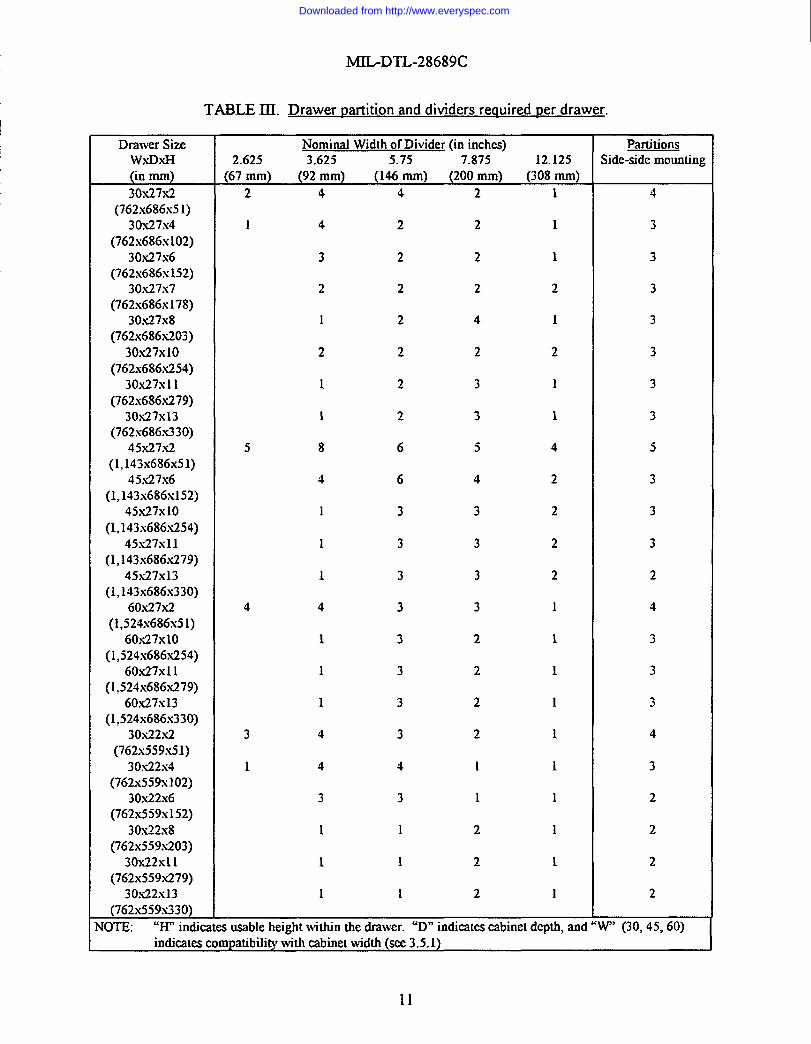
3.5.2.4 Drawer partitions. Each drawer shall be provided with partitions and dividers as specifiedin table III. Installation of the partitions shall utilize machine screws and self-locking nuts tofasten the partitions to the drawer bottom. The height of the partitions and dividers shall be suchthat the tops of all partitions and dividers fdl within 0.25-inch (6 mm) of the top of the drawerside walls, but not extend above any side wall.
10
Downloaded from http://www.everyspec.com
1
I
I
MJL-DTL-28689C
TABLE III. Drawer ~artition and dividers reauired Derdrawer.
Drawer Size Nominal Width of Divider (in inches) PartitionsW.XD.XH 2.625 3.625 5.75 7.875 12.125 Side-side mounting(in mm) (67 mm) (92 MM) (146 mm) (200mm) (308mm)30X27X2 2 4 4 2 1 4
(762x686x51)30.X27X4 1 4 2 2 1 3
(762x686x102)30x27x6 3 2 2 1 3
(762x686x152)30.X27X7 2 2 2 2 3
(762x686x178)30,x27x8 1 2 4 1. 3
(76ZX686X203)30X27XI0 2 2 2 2 3
(762x686.x254)30.X27X11 1 2 3 1 3
(762x686.x279)30X27X13 1 2 3 1 3
(762x686x330)45x27.x2 5 8 6 5 4 5
(1,143x686x51)45,x27x6 4 6 4 2 3
(1,143x686x152)45.X27X1O 1 3 3 2 3
(1,143x686.x254)45X27X11 1 3 3 2 3
(1,143x686.x279)45X27X13 1 3 3 2 2
(1,143x686x330)60.x27.x2 4 4 3 3 1 4
(1,524x686x51)6OS27X1O 1 3 2 1 3
(1,524x686x254)60.x27x11 1 3 2 1 3
(1,524s686.s279)60.x27x13 1 3 2 1 3
(1,524x686x330)30x22x.2 3 4 3 2 1 4
(762x559.x51)30.x22x4 1 4 4 I 1 3
(762.x559x102)30s22s6 3 3 1 1 2
(762.s559x152)30s22x8 1 1 2 1 2
(762.x559.x203)30x22x11 1 1 2 1 2
(762x559x279)30.x22x13 1 1 2 1 2
(762s559s330)Nom: “H” indicatesusable height within the drawer. “D” indicates cabinet depm ~d ‘W” (30, 45, 60) ~
indiealescompatibilitywith cabinetwidth (see3.5.1)
11
Downloaded from http://www.everyspec.com

MIL-DTL-28689C
TABLE ITIa. Drawer t)er wall configuration.
2
6 2
12 8
Drawer Size Nominal Width of Divider (in inches) PartitionsWXDXH STD 20 TRICON D2A or D3C
(in mm) 2A or 2B 4A or 4B 5A or 5B ARMORY AKMORY D2B30X27X2 4 6 2 2
(762x686x51)30X27X4 7 10 1 1
(762x686x102)30x.27x6 4 2 2 1
(762x686x152)30.X27X7 1
(762x686x178)30.X27X8 2
(762x686x203)30X27XI0 1
(762x686x254)30X27X11 1
(762x686.x279)30.X27X13 4 1
(762x686,x330)45.x27.x2 2
(l,143x686.s51)45,x27x6 1
(1,143x686x152)45X27X1O 1
(1,143x686.x254)45.X27X11 1
(1,143x686x279)45.X27X13 3 1
(1,143x686,x330)60.x27x2 1
(1,524x686x5J)6OS27X1O I
(l,524x686.x254)60,x27xI1 2 1
(1,524x686.x279)60x27x13 5 3
(1,524x686.x330)30x22.x2 8
(762x559x51)30s22x4 5
(762x559x102)30.x22x6 6
(762,x559x152)30.x22x8 2
(762x559.x203)30.s22s11 2
(762x559,x279)30x22x13 2
(762x559x330)
12
Downloaded from http://www.everyspec.com

MIL-DTIA8689C
3.5.2.5 Partition anddivider installation. Partitions anddividers shall not reinstalled inthedrawers, but shall be packaged with ail necessary screws and nuts in groups broken down bydrawer heights for all cabinets within a container. These groups shall be clearly marked andshipped in a separate box within the cabinetry configured containers,
3.5.2.6 Drawer covers. In cabinets having drawers of approximately 2 inches(51 mm) usableheight, the top two drawers shall be provided with a rigid clear plastic cover to prevent smallparts from bouncing out of their designated compartments during container handling andtransport. The covers shall be provided with a means of securing them in the closed position.
3.5.2.7 Handles. Drawer handles shall run the fidl length of the drawer fion~ and shall have nosharp edges or protrusions. Handles shall be recessed and shall not extend beyond the front of thecabinet housing. Each handle shall have a snap-on label holder to identi.@the location address ofthe drawer.
3.5.2.8 Interchan~eability. Drawers of the same dimensions shall be interchangeable with oneanother.
3.5.3 Shelves. Slotted shelves shall be provided as required in the drawings. A method ofattaching the shelves that prevent the shelves from vibrating loose from the cabinet housing duringcontainer handling and transport shall be provided, All shelves shall be provided with doors asdescribed in 3.5.4 and 3.5.5.
3.5.3.1 Shelf tie-down strains. Adequate tie-down straps or other restraining devices shall beprovided for each shelf shown in the cabinet~ configuration drawings.
3.5.4 Retractable overhead doors. Where mounting is possible, shelves shall be provided withretractable overhead doors. Each retractable door shall have a positive latching mechanism whichwill secure the door in the fblly closed position.
3.5.5 Hinzed swintin~ doors. Shelf combinations with a height exceeding that which can becovered by a retractable overhead door, shall be provided with hinged swinging doors, hinged atthe outer edge of the cabinet opening. Double doors shall be used on 45-inch (1 143 mm) widecabinets. Each individual door shall have a positive latching mechanism which will secure thedoor in the fblly closed position.
3.5.6 Locking bars. All drawers and doors shall be provided with fill-length vertical hinged barlocks. Each bar lock shall be capable of securing the drawers for the entire cabinet to which it ismounted. Retractable doors shall be provided with hinged locking bars on both sides of theopening. Double doors shall have a single vertical locking bar which will secure both doors at thesame time.
3.6 WeaRons storage racks. The weapons storage racks installed in the armory configurationshown in NAVFAC .Drawing nos. 61,39128and 6139129 shall conform to NSN 1095-00+07-0674.
13
Downloaded from http://www.everyspec.com

MIL-DTL-28689C
3.7 Cabinetrv installation. Cabinetry installation shall be petiormed in a manner which will ensuresecure storage of all equipment and parts for which the containers are intended. As a rninimu~the requirements of 3.7.1 shall be met. Additional provisions required for secure mounting ofcabinetry, which are not specified herein, but are determined by the manufacturer to be necessary,shall be included.
3.7.1 Cabinew mounting. Cabinetry base mount shall extend the fi.dllength of the cabine~ andshall be of sufficient size and strength to withstand the loads imposed by handling when cabinetsare fhlly loaded. The base mount shall be secured to the base of the cabinet and to the floor.Securing the base mount to the floor shall not protrude into the forklift tineways. Cabinetmounting bolts shall not penetrate sheet metal walls of the container. Overhead crossmembers(horizontal struts) shall be securely attached to cabinetry on both sides of the aisle at the top ofeach cabinet. Cabinetry shall be mounted in such a manner that it does not interfere with therestraint system specified in 3.4.10.
3.7.2 Fasteners. All fasteners used in cabinetry installation shall be cadmium plated and shall beof the self-locking type.
3.8 Cleankw and r)ainting. Container and cabinetry surfaces shall be shop-prepared and shop-painted, in accordance with SSPC-SP 10, SSI?C-PA 1, and as specified herein. The surfaceprofile, as measured by ASTM D 4417, shall be 1 to 1.5 roils (0.025 to 0.038 mm) for intenorsurfaca and cabh-tetry,and not greater than 1 mil (0.025 mm) for exterior surfaces and othersurfaces specified in 3.8.2. The appearance of the sutiaces shall be similar to SSPC-VIS 1photograph ASP-10, and the condition of the surfaces shall pass the “water-break” test ofMIL-C-53072, 4.3.3.1. The surfaces shall comply with the specified degree of cleaning, and shallbe dry, immediately prior to application of primers. The total paint films shaJl pass the thickness,adhesio~ and cure tests as specified, and shall be free from runs, sags, orange peel, and otherdefects. Door seals shall not be painted.
3.8.1 Interior Dainting. Painting of container interior surfaces, except as noted in 3.8.2, shallconsist of not less than one coat of primer and one finish coat. The primer shall conform toformula 150, type 1, of MIL-P-2444 U20, and shall be applied to the specified cleq dry surfaceimmediately after cleaning. The dry film thickness of the primer shall be not less than 3.0 roils(0.076 mm) over the entire surface. Paint for the finish coat shall cotiorm to formula 152, type 1,of MIL-P-2444U22, applied to a dry film thickness of not less than 3.0 rnils (O.076 mm) over theentire surface. The total dry film thickness shall be not less than 6.0 rnils (O.152 mm), asmeasured by SSPC-PA 2, and the film shall pass the dry-through test of ASTM D 1640, and theadhesion test of ASTM D 3359, rating 3A. Cabinetry finish shall be as specified in 3.8.3. Thescuff boards shall be treated and painted in accordance with the manufacturer’s standard practice.
3.S.2 Exterior Daintinq. Painting of container exterior surfaces, intenor of the doors, header, anddoor posts shall consist of not less than one coat of primer and not less than two finish coats. Theprimer shall conform to MIL-P-53022, and shall be applied to the specified clean, dry surfaceimmediately afier cleaning. The dry film thickness of the primer shall be not less than 1.5 nils(0.038 mm) over the entire surface. Paint for the finish coat shall be Green 383, conforming to
14
Downloaded from http://www.everyspec.com
MIL-DTL-28689C
either MIL-C-53039 or type IV of ML-C-46168. Before application of the finish coat, spectralreflectance characteristics of the material shall be validated as specified in paragraph 4.2.4 of thespecification selected. The dry film thickness of each applied coat shall be not less than 1.8 rrds(0.046 mm). The dry film thickness of the finish coat shall be not less than 3.6 roils (0.0!31 mm)over the entire surface. The total dry film thickness shall be not less than 5.1 roils (O.13 mm), asmeasured by SSPC-PA 2, and the film shall pass the adhesion test of ASTM D 3359, rating 3A.The cured coating shall pass the d~-through test of ASTM D 1640, arid the solvent wipe test ofM&C-53072, 4.3.3.2.
/
3.8.3 Cabinetw mintinq. Painting of cabinetry surfaces shall consist of not less than one coat of
I primer and one finish coat. The primer shall cunform to formula 150, type 1, of MIL-P-24441/20,and shall be applied to the specified clew dry surface immediately after cleaning. The dry filmthickness of the primer shall be not less than 2.0 roils (0.051 mm) over the entire surface. Paintfor the finish coat shall conform to formula 1.52,type 1, of MIL-P-24441/22, applied to a dry filmthickness of not less than 2.0 roils (0.051 mm) over the entire surface. The total dry film thicknessshall be not less than 4.0 nils (O.102 mm), as measured by SSPC-PA 2, and the film shall pass thedry-through test of ASTM D 1640, and the adhesion test of ASTM D 3359, rating 3A.
3.8.4 Cabinetw hardware. All cabinet~ hardware that is not painted shall be engineered chrome(with a thickness of not less than 2.0 roils (0,051 mm) as specified in ASTM B 650) or stainlesssteeI or electrodeposited zinc coating (with a thickness of not less than 0.5 rnds (0.013 mm), asspecified in ASTM B 633).
3.9 Identification marking. All letters shall be Gothic or Futura capitals with Arabic numeralsand shall read horn left to right. The stenciling medium shall be white color 37875 ofFED-STD-595, confotingtoMIL-C-46168. Stenciling medium shall not rub off of the exteriorsurface of the container when the medium is dry.
3.9.1 Exterior markinq. AUcontainers shall be marked as specified herein. The followinginformation shall be stenciled on the right hand door in 2-inch (51 mm) letters and numerals inaccordance to 1S0 Standards: Tare weight (see 3.4. 1), maximum gross rating, air shipmentmaximum operating weight (type 1 -25,000 pounds (11 340 kg), type II -10,000 pounds(4 536 kg)), shipping cube, and nominal outside dimensions.
3.9.1.1 Data dates. A notierrous metal data plate conforming to A-A-5027 1, shall be aflixed tothe center of the external surface of the right hand door. The method of attachment shall be eitherriveting or bolting. The data plate shall contain the following itiormation (NSNS shall beprovided by the contracting officer):
Downloaded from http://www.everyspec.com

MIL-DTL-28689C
U. S. NAfWCONTAINER SHIPPING AND STORAGE, STEEL WALL (SPECIFY TYPE AND STYLE)SPECIFICATION: M3L-DTL-28689(YD)NSN:Iso coNTHR CONTROL NUMBER:TARE WEIGHT: LBS KGCONTRACT NUMBER:MFD BY:DATE (MONTH & YEAR):
3.9.1.2 ISO container control number. The 1S0 container control number (ICCN) consists ofeleven characters: four letters for the owners code, a six-digit serial number, and a check digit.The ICCN shall be 4 inches (102 mm) hig~ located in accordance with 1S0 6346. The stencilingmedium shall be as specified in 3.9. The ICCNS shall be provided by the contracting officer.
3.9.1.3 CSC dates. A Convention for Safe Containers (CSC) safety approval plate conformingto 49 CFR451, subpart C, with the appropriate itiorrnation stamped, etched, or engraved on itshall be riveted or bolted to the lower left comer of the exterior face of the left hand door of eachcontainer.
3.9.2 Interior marking. The ICCN shall be stamped or welded in characters not less than0.5-inch (13 mm) high on an intenor surface of the upper rear horizontal frame member. Thenumber shall be located where it will not be obscured.
3.10 Workmanshi~. All parts, components, and assemblies of the container including castings,forgings, molded parts, stampings, seals and sealing agents, machined sutiaces, and welded partsshall be clean and free fi-omany defects that will reduce the capability of the container to meet therequirements specified herein. Any components and assemblies which have been repaired ormodified to overcome deficiencies shall not be used without prior specific approval of thecontracting officer. External sutiaces shall be free from burrs, slag, sharp edges, and comersexcept where sharp edges and comers are required. The internal cargo space shall be bee fromsharp protrusions that could damage cargo.
3.10.1 Metal fabrication. Metal used in the fabrication of equipment shall be free iiom kinks andsharp bends. The straightening of material shall be done by methods that will not cause injury tothe metal. Shearing and clipping shall be done neatly and accurately. Comers shall be square andtrue. Flame cutting, using a tip suitable for the thickness of the metal, may be employed insteadof shearing or sawing. Burned surfaces of flame-cut material shall be bee of slag. All bends of amajor character shall be made with controlled means in order to insure uniformity of size andshape. Precautions shall be taken to avoid overheating, and heated metal shall be allowed to coolslowly.
3.10.2 Bolted and riveted connections. Bolt and rivet holes shall be accurately punched or drilledand shall have the burrs removed. Washers, lochvashers, or lock nuts shall be provided where
1,6
Downloaded from http://www.everyspec.com

MIL-DTL-28689C
necessary and all bolts, nuts, and screws shall be tight. Rivet heads, when not countersunk orflattened, shall be of uniform size and shape for the same diameter of rive~ concentric with therivet holes, and in fill contact with the surface of the members.
3.10.3 Welders and welding.
3.10.3.1 Welders. Before assigning any welder to manual welding work covered by thisspecificatio~ the contractor shall provide the contracting officer with certification that the welderassigned to perform welding responsibilities covered by this specification has passed qualificationtest prescribed by AWS D1.1,Section 5, for the type of welding operations to be performed andthat such qualifications are effective as defined by the code.
3.10.3.2 Welding. The surface of parts to be welded shall be free from rust, scale, paint, grease,or other foreign matter. All weld spatter and projections on mating surfaces where members arein contact for fabrication or assembly shall be ground to a suitable flat surface. Weld penetrationshall be such as to provide transference of maximum design stress through the base metaljuncture. Fillet welds shall be provided when necessary to reduce stress concentration. Manualand machine welding processes and materials shall be in accordance with AWS D1. 1.
3.10.4 Machine work. All parts shall be manufactured to gage through the use of jigs andtires and shall provide interchangeability of parts as manufactured.
3.10.5 Castinm. Castings shall be sound and free from patchin~ misplaced coring, warping, ordefects which might render the castings unsound for use.
3.11 Interchangeability. All units of the same classification fimished with similar options under aspecific contract shall be identical to the extent necessary to ensure interchangeability ofcomponent parts, assemblies, accessories, and spare pans.
4. QUALITY ASSURANCE PROVISIONS
4.1 Resuonsibilitv for inspection. Unless otherwise specified in the contract, the contractor isresponsible for the performance of all inspection requirements (examinations and tests) asspecified herein. Except as otherwise specified in the contract, the contractor may use his own orany other facilities suitable for the performance of the inspection requirements specified here@unless disapproved by the Government. The Government reserves the right to petiorm any of theinspections set forth in the specification, where such inspections are deemed necessary to ensuresupplies and setices cotiorm to prescribed requirements.
4.1.1 Res~onsibilitv for compliance. All items shall meet all requirements of sections 3 and 5.The inspection set forth in this document shall become a part of the contractor’s overall inspectionsystem or quality program. The absence of any inspection requirements in this document shall notrelieve the contractor of the responsibility of ensuring that all products or supplies submitted tothe Government for acceptance comply with all requirements of the contract. Samplinginspection, as part of manufacturing operations, is an acceptable practice to ascertain
17
Downloaded from http://www.everyspec.com

MIL-DTL-28689C
cofiormance to requirements, however, this does not authorize submission of known defectivematerial, either indicated or actual, nor does it commit the Government to accept defectivematerial.
4.1.2 Comuonent and material inspection, Components and materials shall be inspected inaccordance with ail the requirements specified herein and in applicable referenced documents.
4.2 Classification of inst)ections. The inspection requirements specified herein are classified asfollows:
a. First article inspection (see 4.2.1).b. Quality cotiormance inspection (see 4.2.2).
4.2.1 First article inspection. The first article inspection shall be performed on the containerslisted in 3.2 when a first article is required (see 3.2 and 6,2). This inspection shall include theexamination of4.4 and the tests of4.5.2 thru 4.5.4. The tests of4.5.3 shall be performed on threetype II, style 1 containers coupled in the equivalent of an ISO series lC configuration. The firstarticle test shall be performed by the contractor under the direction and in the presence ofGovernment representatives. Failure to pass any of the required tests shall be cause for theGovernment to refise acceptance of all containers until corrective action has been taken. Thefirst article may be either a first production item or a standard production item born the supplier’scurrent inventory provided the item meets the requirements of this specification and isrepresentative of the design, construction, and manufacturing technique applicable to theremaining items to be firnished under the contract. In the event the contractor desires to deliverthe test model as a contract ite~ it shall be delivered as the last item on the contract only after thecontractor, at tis own cost and expense, shall have completely cleaned, reconditioned, andoverhauled the unit, making such replacements and modifications thereto as are required to makethe unit acceptable as a contract item. Acceptance of first article shall not constitute a waiver bythe Government of its rights under provisions of the contract.
4.2.1.1 CSC certification. A copy of test reports documenting the results of containercertification testing conducted in accordance with 4.5.1, shall be made available for Governmentinspection prior to the first article inspection.
4.2.1.2 Standards compliance. The contractor shall make available to the contracting officer orhis authorized representative evidence of compliance with the applicable standards cited in thisspecification.
4.2.2 Oualitv conformance ins~ection. The quality conformance inspection shall be petiorrned onitems selected in accordance with 4.3 and shall consist of the examination of 4.4.
4.3 Ins~ection. All containers offered for delivery at one time shall be inspected for conformanceto all contract requirements. If a container is rejected, the contractor may rework it to correct thedefects, and resubmit for a complete reinspection, Resubmitted containers shall be reinspectedusing tightened inspection. If the rejected container was screened, reinspection shall be limited to
18
Downloaded from http://www.everyspec.com

.. . .
MIL-DTL-28689C
the defect causing rejection. Rejected containers shall be separate from new containers, and shallbe clearly identified as reinspected containers.
4.4 Examination. The first article, and each container selected thereafter in accordance with 4.3,shall be examined for compliance with the requirements specified in section 3 and table IV of thisspecification.
TABLE IV. Classification of defects.
Classification Defects RequirementParagraph
Major:101102103104105106107108109110111112113114115116117118119120121122123124125
126127128129130131
Materials not as specified.Container construction not as specified.Weight not as specified.Dimensions not as specified.Floor construction not as specified.“Understructure not as specified.Forklift pockets not as specified.Roof construction not as specified.Doors not constructed as specified.Door gasket not as specified.Comer fittings not as specified.Antipilferage provisions not as specified.Restraint system not as specified.Tie-down eyes not as specified.Tie-down rods not as specified.Captive couplers not as specified.Power suppiy cord port not as specified.Container vents not as specified.* Housing not as specified.* Drawers not as specified.* Drawer working load not as specified.* Suspension system not as specified.* Lock-in lock-out system not as specified.* Drawer partitions not as specified.* Insufficient number of drawer partitions
and dividers.* Drawer covers not as specified.* Handles not as specified.* Drawers not interchangeable.* Shelves not as specified.* Doors not as specified.* Locking bars not as specified.
3.33.43.4.13.4.23.4.43.4.53.4.5.13.4.63.4.73.4.7.13.4.83.4.93.4.103.4.113.4.123.4.133.4.143.4.153.5.1.3.5.23.5.2.13.5.2.23.5.2.33.5.2.43.5.2.4.1
3.5.2.53.5.2.63.5.2.73.5.33.5.4,3.5.53.5.6
19
Downloaded from http://www.everyspec.com
MIL-DTL-28689C
I TABLE IV. Classification of defects. - Continued
1 Classification Defects RequirementParagraph
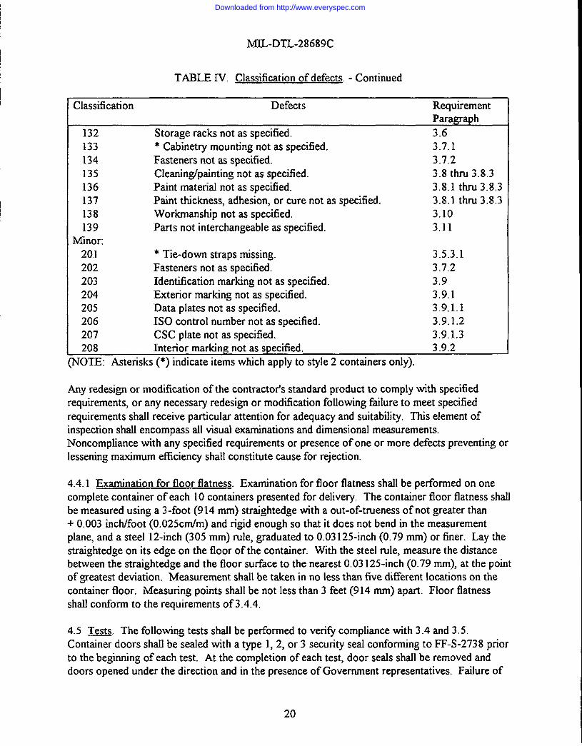
132 Storage racks not as specified. 3.6133 * Cabinetry mounting not as specified. 3.7.1134 Fasteners not as specified. 3.7.2135 Cleaning/painting not as specified. 3.8 thru 3.8.3136 Paint material not as specified. 3.8.1 thru 3.8.3137 Paint thickness, adhesion, or cure not as specified. 3.8.1 thru 3.8.3138 Workmanship not as specified. 3.10139 Parts not interchangeable as specified. 3.11
I I Minor:201 * Tie-down straps missing. 3.5.3.1202 Fasteners not as specified. 3.7.2203 Identification marking not as specified. 3,9204 Exterior marking not as specified. 3.9.1205 Data plates not as specified. 3.9.1.1206 1S0 control number not as specified. 3.9.1.2207 CSC piate not as specified. 3.9.1.3208 Interior marking not as specified. 3.9.2
(NOTE: Asterisks (*) indicate items which apply to style 2 containers only).
Any redesign or modification of the contractor’s standard product to comply with specifiedrequirements, or any necessary redesign or modification following ftilure to meet specifiedrequirements shall receive particular attention for adequacy and suitability. This element ofinspection shall encompass all visual examinations and dimensional measurements.Noncompliance with any specified requirements or presence of one or more defects preventing orlessening maximum efficiency shall constitute cause for rejection.
4.4.1 Examination for floor flatness. Examination for floor flatness shall be pefiormed on onecomplete container of each 10 containers presented for delive~. The container floor flatness shallbe measured using a 3-foot (914 mm) straightedge with a out-of-tmeness of not greater than+ 0.003 inch/foot (0.025 Cm/m) and rigid enough so that it does not bend in the measurement
plane, and a steel 12-inch (305 mm) rule, graduated to 0.03 125-inch (0.79 mm) or finer. Lay thestraightedge on its edge on the floor of the container. With the steel rule, measure the distancebetween the straightedge and the floor surface to the nearest 0.03 125-inch (0.79 mm), at the pointof greatest deviation. Measurement shall be taken in no less than five different locations on thecontainer floor. Measuring points shall be not less than 3 feet (914 mm) apart. Floor flatnessshall conform to the requirements of 3.4.4,
4.5 Tests. The following tests shall be performed to veri@ compliance with 3.4 and 3.5.Container doors shall be sealed with a type 1,2, or 3 security seal conforming to FF-S-2738 priorto the beginning of each test. At the completion of each test, door seals shall be removed anddoors opened under the direction and in the presence of Government representatives. Failure of
20
Downloaded from http://www.everyspec.com

MIL-DTL-28689C
Iany test shall be cause for rejection of containers and shall be cause for the Government to deferfbture acceptance until objective evidence finished by the supplier indicates that deficienciesrevealed by the tests have been corrected. The CSC certification tests and the test of 4.5.4 shallbe performed on container, with all cabinetry removed from the container.
4.5. I CSC certification tests. Container certification test shall be witnessed by and CSC certifiedby an authority approved by the United States Coast Guard. For CSC certificatio~ type Icontainers shall be tested as specified in 1S0 1496-1, type XIcontainers (TRICONS) shall betested as specified in 4.5.1.1 thru 4.5,1.11. Test No. 8 of 1S0 1496-1 does not apply to type II
Icontainers. Test 13 of 1S0 1496-1 shall be petiormed last.
I
4.5.1.1 Test No. 1: Stacking. Three coupled containers in the lC configuration shall be testedfor stacking in accordance with 1S0 1496-1. The value of R shall be 44,800 pounds (20 321 kg)Ifor each tier of lC containers or configurations.
4.5.1.2 Test No. 2: Lifting from the to~ comer fittinas. Three coupled containers in the lCconfiguration shall be tested for Mling from the top comer fittings with the IiRing forces appliedvertically in accordance with 1S0 1496- 1,,and the value of R shall be 44,800 pounds (20 321 kg)for the lC configuration. The single type II container (TRICON) shall be tested with theappropriate sling angle, and the value of R shall be 14,900 pounds (6 759 kg).
4.5.1.3 Test No. 3: Lifting I%omthe bottom comer fittirws. Three coupled TRICONS in thelC configuration shall be tested for IiRingfrom the bottom comer fittings in accordance with1S0 1496-1, in which case the sling angle is 45 degrees to the horizontid and the value of R is44,800 pounds (20 321 kg). The single TRICON shall be tested, in which case the sling angle is60 degrees to the horizontal and the value of R is 14,900 pounds (6 759 kg).
4.5.1.4 Test No. 4: Restraint. Three coupled TRICONS in the 1C configuration shall be testedfor restraint in the longitudinal direction in accordance with 1S0 1496-1 and the value of R shallbe 44,800 pounds (20321 kg). The single TRICON shall be tested for restraint in the lateraldirection and the value of R shall be 14,900 pounds (6 759 kg).
4.5.1.5 Test No. 5: Strerwth of end walls. One end wall, defined by the height and width of asingle TRICON, shall be tested for strength in accordance with 1S0 1496-1. The value of P shallbe 12,200 pounds (5 534 kg) (14,900 pounds (6 759 kg) maximum gross weight minus2,700 pounds (1 225 kg) maximum tare weight without cabinetry). Testing the end walls of the1C configuration is not required.
4.5.1.6 Test No. 6: Stremzth of side walls. Both side walls, defined by the height and length of asingle TIUCON, shall be tested for strength, one at a time, The test procedure shall be the sameas the end wall testing of the TRICON in 4.5.1.5 in accordance with 1S0 1496-1. Three coupledTRICONS in the lC configuration shall be tested for strength of sided wall in accordance with1S0 1496-1. The test of coupled containers is to determine the adequacy of the connectors andframes as well as the side panels. Both side walls shaJlbe tested, one at a time. The value of Pshall be 36,600 pounds (16 602 kg) (12,200 pounds (5 534 kg) per container).
21
Downloaded from http://www.everyspec.com

MIL-DTL-2S689C
4.5.1.7 Test No. 7: Stren,@hof the roof. The roof of a single TRICON shall be tested inaccordance with ISO 1496-1,
4.5. ”1.8Test No. 9: Transverse riziditv. Three coupled TRICONS in the lC configuration shallbe tested for transverse rigidity in accordance with 1S0 1496-1.
4.5.1.9 Test No. 10: Longitudinal rigidity. Three coupled TRICONS in the 1C configurationshall be tested for longitudinal rigidity in accordance with ISO 1496-1.
.4.5.1.10 Test No. 11: LifhR from forklift Dockets. The lateral forklift tineways of a singleTRICON, with one set of pockets on each side of the container, shall be tested in accordance with1S0 1496-1. The value of R shall be 14,900 pounds (6 759 kg).
4.5.1.11 Test No. 13: Weathemroofhess, Each of the three type II containers shall be tested forweatherproofiess in accordance with 1S0 1496-1.
4.5.2 Door test. The doors of the containers shall be opened and engaged to the securing deviceson the side walls. Each door, while secured, shall be pulled with a force of 150 pounds (68 kg).Failure of the door to remain attached to the securing device shaIl constitute ftilure of the test.The doors shall then be closed. Failure of the doors to close tightly or fiiilure of the handles tolock shall constitute failure of the test.
4.5.3 Simulated load test. The first article containers shall have the load determined in thefollowing manner. For the bulk containers (style 1), the manufacturer shall determine the totalweight of the container (tare weight as defined in 3.4.1). This figure shall then be subtracted fromthe maximum operating weight of 25,000 pounds(11 340 kg) for type 1, and 10,000 pounds(4 536 kg) for type II containers. The result is the load capacity (L) for that container. The testload shall be evenly distributed in the container. The test load shall be secured to prevent it fromshifting during the test. For the configured containers (style 2), the manufacturer shall determinethe total weight of the container and installed cabinetry (tare weight as defined in 3.4.1). Thisfigure shall then be subtracted from the air shipping maximum operating weight of 25,000 pounds(11 340 kg) for type I, and ‘1O,OOOpounds (4 536 kg) for type II. The result is the L for thatcontainer. One drawer or shelves in each stack of cabinetry shall be loaded with 240 pounds(109 kg). These test loads shall be distributed to various levels within the wall configuratio~ withno more than two of these weights at any particular level. All other drawers and shelves shall beloaded with 160 pounds (73 kg), except drawers with less than 4 inches(102 mm) of usable heightmay have less than 160 pounds (73 kg). After loading all drawers and shelves with the prescribedtest weights, sufficient weight shall be loaded in the aisles to bring the total test weight of thecontainers to 25,000 pounds (11 340 kg) for a type I container, and 10,000 pounds (4 536 kg) for atype II container. Three type II containers coupled using captive connecting devices described in3.4.13, shall form an integral 20-foot (6 096 mm) equivalent unit (TEU). Each of the type Icontainers and the TEU (connected type II containers) shall then be tested as described in 4.5.3.1thru 4.5.3.3. Test of4.5.3.2 is for style 2 containers only.
22
Downloaded from http://www.everyspec.com

MIL-DTL-28689C
4.5.3.1 Rotational drop test. Place one bottom rail of thecontainer being tested onanominaJ4-iich (102 mm) high block. Raise the opposite bottom rail of the container 12 inches (305 mm)and then allow the unit to fall freely onto a concrete surface using the 4-inch (102 mm) block as apivot. Perform this test once on each of the four bottom rails of the container.
4.5.3.2 Rail impact test. The railcars shall be American Association of Railroads (AAR)approved for domestic rail freight service. The test car (hammer car) shall be AAR approved forcontainer on flatcar service. The buffer cars shall have no cushioning devices other than standardpocket draft gears. The containers shall be secured to the test car using the test car’s AARapproved locking fittings. The container being tested, loaded as described in 4.5.3, shall bemounted on a rail car and subjected to a series of impacts at 4 to 6 miles per hour (mph) (6.4 to9.7 kdometers per hour (km/h)) against five empty freight cars with their brakes set and drafl gearextended. Each container shall be impacted twice in each direction at 4 to 6 mph(6.4 to 9.7 (km/h)) for a total of four impacts. Once the test has begun, there shall be noreadjustment of load, nor any reconditioning of the tie-downs except as necessary to reverse thedirection of the container.
4.5.3.3 Movhw test. The container being tested shall be mounted on a single chassis with tandembogie and platform body, loaded as specified. The container shall be towed for not less than250 miles (403 km) at variable speeds up to 55 mph (89 km/h) over hard surface roads, and fornot less than 100 miles (161 km) at variable speeds up to 35 mph (56 km/h) over unpaved roads.
4.5.4 Simulated rainfall test. Simulated rainfall test shall be performed on one complete containerof each 10 containers presented for delive~. Simulated rainfidl shall be produced by a waterdistribution device of such design that the water is emitted in the form of droplets, is disperseduniformly over the top, side surfaces, and doors of the container, and impinges directly on thesurfaces at an angle of 45 degrees from the vertical, The top and each side of the container shallbe exposed to simulated rainfall, at a constant rate of 4.5 * 0.5 inches(114 k 13 mm) per hour,for a period of 15 minutes on each side of the container. The use of tape, sheet plastic, caulkingor any other weatherproofing techniques is not permitted. Any water leakage, either during therain test or during actual rain conditions (should they occur) will be considered evidence that thecontainer is not weatherproof, and will require repair and additional testing prior to acceptance.
4.5.5 Failure criteria. Each container shall be inspected after evety test for compliance.Cabinetry is not to be removed from containers between tests. Any of the following shallconstitute ftilure of any of the tests specified in 4.5:
a. Deflection of the container bottom side rails or bottom end frame members of more than0.25-inch (6 mm) below the bottom plane of the bottom comer fittings.
b. Deflection of the container crossmembers below the limits specified in 3.4.5.
c. Evidence of weld failure.
d. Permanent deformation.
23
Downloaded from http://www.everyspec.com
MIL-DTL-28689C
e.
f
fii
h.
i.
j.
k.
1.
m
n.
o.
Any broken or tom component.
Any detachment of a gasket.
Inability of one man standing on the ground to open or close a door without the use oftools while the container is sitting on level ground.
Inability of one man standing on the ground to operate a latching mechanism without theuse of tools while the container is sitting on level ground.
Detachment of cabinet~ 120mmounting system.
Failure of any cabinetry mounting and bracing system components.
Failure of drawers and shelves to support specified loads.
Failure of drawers to operate without binding.
Any dimensions after a test not within the specified tolerance.
Penetration of water into the interior of the container.
Failure of the captive connecting devices to maintain a tight connection (type 11containers).
5. PACKAGING. The presemation, packing, and marking shall be as specified in the contractororder.
6. NOTES
(This section contains information of a general or explanatory nature that maybe helpfld, but isnot mandato~.)
6.1 Acquisition recwirements. Acquisition documents must speci~ the following:
a. Title, number, and date of this specification.b. Type and style required (see 1.2.l).c. Number of containers, and of the type, style, and configuration required for and approval
(See 3.2 and 4.2.1).
24
Downloaded from http://www.everyspec.com

.MIL-DTL-28689C
6.2 National Stock Numbers (NSN). NSNS applicable to this document areas follows;
NSN Nomenclature1095-00-407-0674 Gun rack5410-01-363-7086 Connectors8110-01-286-7464 Plug, expansion 2-inch inside
8145-01-287-32938145-01-287-32948145-01-287-32958145-0’1-287-85638145-01-287-85648145-01-287-85658145-01-287-85668145-01-287-85678145-01-288-96978145-01-289-09448145-01-289-09458145-01-289-33668145-01-289-33678145-01-289-33688145-01-289-43298145-01-290-1382
container
STD 20TRICONSTD 20TR.ICONTRICONSTD 20STD 20STD 20STD 20STD 20TRICONSTD 20STD 20STD 20TIUCONSm 20
Wall Confkuration
- -/5BBulk4A/4BAJmolyD3CArmory5A/5BBulk4A15B4A/3BD2A/D2B3A/ 2B2A/5B3A/5BDIA/DIB4A/--
6.3 Subject term (kev word) listing.
BulkConfiguredISO containerTRICON
6.4 Datareauirements. When this specification isusedin an acquisition and dataare required tobe delivered, thedata requirements shall be developed asspecified by anapprovedData ItemDescnption(DDForm 1664) and delivered inaccordance with the approved ContractDataRequirementsLkt(DDForm1423) incorporated intothecontract. When the provisionsofDoDFederal Acquisition Regulations(FAR) Supplement,Part 27, Sub-Part 227.405-70 areinvokedandtheDD Form 1423 is not used, the data should be delivered bythe contractor in accordancewith the contract or purchase order requirements.
25
Downloaded from http://www.everyspec.com
MIL-DTL-28689C
6.5 first article. When a first article inspection is required, the item will be tested and should
first production item, or it may be a standard production item from the contractor% current
invento~ as specified in 4.2.1. The first article should consist of one of each style of type Icontainer and three of the type Ill containers. The contracting offker should include specific
be a
instructions in acquisition documents regarding arrangements for examination, test, and approvalof the first article.
Custodian: Pre~arin~ Activity:Navy -YDl Navy - YDlA&my - GL
Review Activities: (Project 8145-0061)
Navy - OS
26
Downloaded from http://www.everyspec.com