
MIL-D-18641F(SH) MILITARY SPECIFICATION DISTILLATION …
64
MIL-D-18641F(SH) 5 April 1993 SUPERSEDING MIL-D-18641E(SHIPS) 30 August 1%0 MILITARY SPECIFICATION DISTILLATION UNITS, WATER STEAM, OR FLASHED VAPOR OPERATED, OR HOT FRESH WATER HEATED, LOW PRESSURE NAVAL SHIPBOARD This specification is approved for use by the Naval Sea Systems Command Department of the Navy, and is available for use by all Departments and Agencies of the Department of Defense. 1. SCOPE 1.1 Scope This specification covers low pressure steam or hot fresh water (heat recovery) heated vacuum operated distillation units for making fresh water from sea water in, Naval shipboard installations. 1.2 Classification. 1.2.1 Types Distillation units should be of the following types as specified (see 6.2): Type I Submerged tube type, low pressure steam operated Type II Flash type, low pressure steam operated Type III Vertical basket type, low pressure steam operated Type IV Flash type, hot fresh water heated (heat recovery) Type V Submerged tube, hot fresh water heated (heat recovery) Beneficial comments (recommendations, additions, deletions) and any pertinent data which may be of use in improving this document should be addressed to: Commander, Naval Sea Systems Command SEA 05Q42, 2431 Jefferson Davis Hwy, Arlington, VA 22242-5160 by using the self- addressed Standardization Document Improvement Proposal (DD Form 1426) appearing at the end of this document or by letter. AMSC N/A FSC 4620 DISTRIBUTlON STATEMENT A. Approved for public release; distribution is unlimited. Downloaded from http://www.everyspec.com
Transcript of MIL-D-18641F(SH) MILITARY SPECIFICATION DISTILLATION …
MIL-D-18641F(SH)5 April 1993SUPERSEDINGMIL-D-18641E(SHIPS)30 August 1%0
MILITARY SPECIFICATION
DISTILLATION UNITS, WATER STEAM, OR FLASHED VAPOR OPERATED, ORHOT FRESH WATER HEATED, LOW PRESSURE NAVAL SHIPBOARD
This specification is approved for use by the Naval Sea Systems Command Departmentof the Navy, and is available for use by all Departments and Agencies of theDepartment of Defense.
1. SCOPE
1.1 Scope This specification covers low pressure steam or hot fresh water (heat recovery)heated vacuum operated distillation units for making fresh water from sea water in, Naval shipboardinstallations.
1.2 Classification.
1.2.1 Types Distillation units should be of the following types as specified (see 6.2):
Type I Submerged tube type, low pressure steam operatedType II Flash type, low pressure steam operatedType III Vertical basket type, low pressure steam operatedType IV Flash type, hot fresh water heated (heat recovery)Type V Submerged tube, hot fresh water heated (heat recovery)
Beneficial comments (recommendations, additions, deletions) and any pertinent data which maybe of use in improving this document should be addressed to: Commander, Naval Sea SystemsCommand SEA 05Q42, 2431 Jefferson Davis Hwy, Arlington, VA 22242-5160 by using the self-addressed Standardization Document Improvement Proposal (DD Form 1426) appearing at theend of this document or by letter.
AMSC N/A FSC 4620
DISTRIBUTlON STATEMENT A. Approved for public release; distribution is unlimited.
Downloaded from http://www.everyspec.com

MIL-D-18641F(SH)
1.2.2 Classes Distillation units should be of the following classes, as specified (see 6.2):
class 1 Composition 70-30 copper-nickel alloy for submarineapplication
class 2 Composition 90-10 copper-nickel alloy for surface shipapplication.
2. APPLICABLE DOCUMENTS
2.1 Government documents.
2.1.1 Specifications, standards, and handbooks. The following specifications, standards, andhandbooks form a part of this document to the extent specified herein. Unless otherwise specified,the issues of these documents shall be those listed in the issue of the Department of DefenseIndex of Specifications and Standards (DODISS) and supplement thereto, cited in the solicitation(see 6.2).
SPECIFICATIONS
FEDERAL
PPP-B-601PPP-B-621QQ-N-281
QQ-N-286
QQ-N-288
TT-P-28
MILITARY
MIL-C-104
MIL-P-116
MIL-B-121
MIL-C-132MIL-S-901
Boxes, Wood, Cleated-PlywoodBoxes, Wood, Nailed and Lock-CornerNickel-Copper Alloy Bar, Rod, Plate, Sheet, Strip, Wire,Forgings, and Structural and Special Shaped SectionsNickel-Copper-Aluminum Alloy, Wrought (UNS N05500)
Nickel-Copper Alloy and Nickel-Copper-Silicon Alloy Castings
Paint, Aluminum, Heat Resisting (1200 °F)
Crates, Wood: Lumber and Plywood Sheathed, Nailed andBolted
Preservation, Methods of .
Barrier Material, Greaseproof Waterproofed, Flexible
Crate, Wood Open; Maximum Capacity 2,500 PoundsShock Tests, HI (High Impact); Shipboard Machinery,Equipment and Systems, Requirements for
2
Downloaded from http://www.everyspec.com

MIL-D-18641F(SH)
MIL-E-917
MIL-S-1222
MIL-M-2082
MIL-G-2860MIL-C-3774
MIL-P-5425
MIL-G-5514
MIL-T-15005
MIL-P-15024
MIL-P-l5024/5
MIL-S-15103MIL-E-15465MIL-C-15726
MIL-P-15742
MIL-E-15809MIL-V-16556
MIL-I-17244
MIL-P-17639
MS 17828
MIL-P-17840
MIL-V-l8030
MS 18116
Electric Power Equipment BasicShipboard Use)Studs, Bolts, Hex Cap Screws, SocketNuts
Meters, Flow, Mechanical, Volumetric
Requirements (Naval
Head Cap Screws, and
Positive Displacement,Liquid, Cold Water and Hot Water Type, Naval ShipboardUse
Glasses, Sight-Flow, Clear, Borosilicate
Crates, Wood; Open 12,000- and 16,000-Pound Capacity
Plastic Sheet, Acrylic, Heat Resistant
Gland Design, Packings, Hydraulic, General Requirement for
Tubes, 70-30 and 90-10 Copper Nickel AlloyHeat ExchangerPlates, Tags and Bands for Identification of
Condenser and
Equipment
Plates, Identification
Salinity Indicating EquipmentEjector Assemblies, Air
Copper-Nickel Alloy, Sheet, Plate, Strip, Bar, Rod and Wire
Plugs, Plastic (Heat-Exchanger-Tube)
Expander, Tube, Condenser and Heat ExchangersValve, solenoid, Three-Way Bypass (Naval Shipboard Use)Indicators, Temperature, Direct-Reading, Bimetallic, (3 and5 Inch Dial)
Pump, Centfigal, Miscellaneous Service, (Naval Shipboarduse)
Nut, Self-Locking, Hexagon, Regular-Height, (Non-MetallicInsert) 250 “F, Nickel-Copper Alloy
Pumps, Centrifugal, Close-Coupled, Navy Standard (ForSurface Ship Application)
.
Valves, Control, Air-Diaphragm-Operated (Complete withinstrumentation)Bolt, Stud, and Socket Head Cap Screw, Nickel-Copper-Aluminum Alloy
3
Downloaded from http://www.everyspec.com

MIL-D-18641F(SH)
MS 18288MIL-P-18472
MIL-V-18683
MIL-G-18997MIL-A-19521
MIL-T-19646
MIL-I-20037
MIL-V-20065
MIL-C-20159MIL-R-21252
MIL-P-21397
MIL-E-21562
MIL-G-21610
MIL-E-22200MIL-E-22200/3
MIL-E-22200/4
MIL-N-24106MIL-T-24107
MIL-T-24270
MIL-L-24479
MIL-B-24480
LockplatePumps, Centrifugal, Condensate, Feed Booster Waste HeatBoiler and Distilling Plant
Vacuum Pumps, Power Driven, Centrifugal Pump PrimingService, Naval Shipboard
Gauge, Pressure, Dial Indicating
Anodes, Corrosion Preventive, Zinc and Plugs, Zinc AnodeRetaining; Design of and Installation in Shipboard Condensersand Heat Exchangers
Thermometers, Remote Reading, Self-Indicating Dial, GasActuatedIndicators, Sight, Liquid Level, Direct/Indirect Reading,Tubular Glass/PlasticValves, Angle, Pressure Relief, Naval Shipboard, for SteamServiceCopper-Nickel Alloy Castings (UNS No. C76200 and C76400)Rubber Sheet, Solid, Synthetic, Shipboard Water EvaporatorGasketingProportioning Unit, Chemical (For Distilling Plants NavalShipboard Use)Electrodes and Rods – Welding, Bare, Nickel Alloy
Gaskets, Heat Exchanger, Various Cross Section Rings,Synthetic Rubber
Electrodes, Welding, Covered: General Specification forElectrodes, Welding, Covered: Nickel Base Alloy and CobaltBase Alloy
Electrodes, Welding, Covered, Copper-Nickel Alloy
Nickel-Copper Alloy Bars, Rods, and ForgingsTube, Copper (Seamless) (Copper Alloy Numbers C10100,C10200, C10300, C10800, C12000, C12200, and C14200)
Thermowells for Thermometers and Electrical TemperatureSensors, General Specification for
Lubricant, Red Lead and Graphite in Mineral OilBronze, Nickel-Aluminum (UNS No. C95800) Castings, forSeawater Service
4
Downloaded from http://www.everyspec.com

MIL-D-18641F(SH)
MIL-C-24643
DOD-D-24577
MIL-A-24696
MIL-P-24691
MIL-P-24691/l
MIL-R-83248
STANDARDS
MILITARY
MIL-STD-129
MIL-STD-167-1
MIL-STD-271
MIL-STD-278MIL-STD-438
MIL-STD-740-1
MIL-STD-740-2
MIL-STD-777
Cables and Cords Electrical, Low Smoke, for Shipboard Use,General Specification for
Distiller Scale Preventative Treatment Formulations (Metric)Gasket, Sheet, Non-AsbestosPipe and Tube, Carbon, Alloy and Stainless Steel, Seamlessand Welded, General Specification for
Pipe and Tube, Carbon Steel, Seamless
Rubber, Fluorocarbon Elastoner, High Temperature, Fluid,and Compression Set Resistant
Marking for Shipment and Storage
Mechanical Vibrations of Shipboard Equipment (Type I -Environmental and Type II - Internally Excited)Requirements for Nondestructive Testing MethodsWelding and Casting Standard
Schedule of Piping, Valves, Fittings, and’ Associated PipingComponents for Submarines Service
Airborne Sound Measurements and Acceptance Criteria ofShipboard Equipment
Structureborne Vibratory Acceleration Measurements andAcceptance Criteria of Shipboard Equipment
Schedule of Piping, Valves, Fittings, and Associated PipingComponents for Naval Surface Ships
DOD-STD-1399, Interface Standard for Shipboard Systems Ship MotionSection 301 and Attitude (Metric)
(Unless otherwise indicated, copies of federal and military specification, standards, and handbooksare available from the Naval Publications and Forms Center, (ATTN: NPODS), 5801 TaborAvenue, Philadelphia, PA 19120-5099.)
.
2 .1 .2 o ther Government documents drawing and publications. The following otherGovernment documents drawings, and publications form a part of this document to the extentspecified herein. Unless otherwise specified, the issues are those cited in the solicitation.
5
Downloaded from http://www.everyspec.com

MIL-D-18641F(SH)
DRAWINGS
NAVAL SEA SYSTEMS COMMAND (NAVSEA)
B 214 Root Connections for Attaching Pipe803-5959186 Submarine Heat Exchanger Anode Plug803-1385541 Valves, Bronze Flanged, B-135, Globe
(Application for copies should be addressed to: Commander, Portsmouth Naval Shipyard, Code202.2, Portsmouth, NH 03801.)
PUBLICATIONS
NAVSEA
0900-LP-001-7000 Fabrication and Inspection of Brazed Piping SystemO9O8-LP-OOO-3O1O Surface Ship Shock Design CriteriaT9070-M-DDT-010/(C) Design Data for Submarine Combatants, Nuclear PoweredSUBS Ship Motion Design Criteria
(Application for copies should be addressed to the Naval Publications and Forms Center, (ATTN:NPODS), 5801 Tabor Avenue, Philadelphia, PA 19120-5099.)
2.2 Non-Government publications. The following documents form a part of this documentto the extent specified herein. Unless otherwise specified, the issues of the documents which areDOD adopted are those listed in the issue of the DODISS cited in the solicitation. Unlessotherwise specified the issues of documents not listed in the DODISS are the issues of thedocuments cited in the solicitation (see 6.2).
AMERICAN NATIONAL STANDARDS INSTITUTE (ANSI)
B1.1 Unified Inch Screw Threads (UN and UNR Thread Form); (DOD adopted)B1.12 Class 5 Interference-Fit Thread
(Application for copies should be addressed to the American National Standards Institute, 1430Broadway, New York, NY 10018.)
Downloaded from http://www.everyspec.com

MIL-D- 18641F(SH)
AMERICAN SOCIETY OF MECHANICAL ENGINEERS (ASME)
Boiler and Pressure Vessel Code, Section 111, Nuclear Power Plant Components
(Application for spies should be addressed to the American Society of Mechanical Engineers,345 East 47th Street, New York, NY 10007.)
AMERICAN SOCIETY FOR TESTING AND MATERIALS (ASTM)
A 285
A 515
B 61B 111
B 127
B 151
B 152
B 164
B 171
B 584
D 512
D 3951F 1166
Standard Specification for Pressure Vessel Plates, Carbon Steel, Low- andIntermediate-Tensile Strength; (DOD adopted)Standard Specification for Pressure Vessel Plates, Carbon Steel, forIntermediate- and Higher-Temperature Service; (DOD adopted)Standard Specification for Steam or Valve Bronze Castings; (DOD adopted)Standard Specification for Copper and Copper-Alloy Seamless Condenser Tubesand Ferrule Stock; (DOD adopted)
Standard Specification for Nickel-Copper Alloy (UNS N04400) Plate, Sheet,and Strip; (DOD adopted)
Standard Specification for Copper-Nickel-Zinc Alloy (Nickel Silver) andCopper-Nickel Rod and Bar; (DOD adopted)
Standard Specification for Copper Sheet, Strip, Plate, and Rolled Bar:(DOD adopted) .Standard Specification for Nickel-Copper Alloy Rod, Bar, and Wire;(DOD adopted)Standard Specification for Copper-Alloy Plate and Sheet for PressureVessels, Condensers, and Heat Exchangers
Standard Specification for Copper Alloy Sand Castings for GeneralApplications; (DOD adopted)
Standard Test Methods for Chloride Ion in WaterStandard Practice for Commercial Packaging; (DOD adopted)
Standard Practice for Human Engineering Design for Marine Systems,Equipment, and Facilities
(Application for copies should be addressed to the American Society for Testing and Materials,1916 Race Street, Philadelphia, PA 19103.)
(Non-Government standards and other publications are normally available from the organizationsthat prepare or disribute the documents. These documents also may be available in or throughlibraries or other informational services.)
Downloaded from http://www.everyspec.com

2.3 Order of precedence In thethe references cited herein, the text of
MIL-D-18641F(SH)
event of a conflict between the text of this document andthis document takes precedence. Nothing in this document,
however, supersedes applicable laws and regulations unless a- specific exemption ‘has been obtained.
3. REQUIREMENTS
3.1 Qualification. Water distillation units furnished under this specification shall be productswhich are authorized by the qualifying activity for listing on the applicable qualified products listat the time of award of contract (see 4.2 and 6.5).
3.2 Shock resistance. Shock tests of complete distillation units or separately mountedcomponents thereof weighing approximately 400,000 pounds (this weight includes the weight of theunit or component, test fixture, ancillary equipment and fluids) or less are required (see 4.4 and6.2).
33 Dynamic analysis. Distilling units which cannot be shock tested shall be dynamicallyanalyzed in accordance with NAVSEA 0908-LP-000-3010. The distilling units, sub-bases, feet,structural members
3.4 vibration(see 4.5).
3.5 Airborne
and hold down bolts shall be included in the analysis.
Distilling units shall be subject to the requirements of MIL-STD-167-1
and structureborne noise. Distilling units shall meet the requirements of -MIL-STD-740-1 for airborne noise of grade B equipment and in accordance with MIL-STD-740-2for structureborne noise (see 4.6).
3.6 Reliability. The mean-time-between-failures (MTBF) and mean-time-to-repair (MTTR)shall be as specified (see 6.2 and 6.3).
3.7 Maintainability. The distilling unit shall be such that al! maintenance, both corrective andpreventive, can be accomplished at the organizational level with no outside assistance. Preventiveand corrective maintenance shall be demonstrated by successful completion of the maintainabilitydemonstration (see 6.3). Demonstration within the maintenance envelope dimensions is required.
3.8 Safety. Safety design features, including fail safe features, shall be incorporated into thedesign to prevent damage to equipment and to ensure optimal personnel protection duringoperation, repair or interchanging of any component or assembly.
3.8.1 One-button shutdow. Distilling units for submarines shall accommodate a one-buttonshutdown of the unit which will safely secure all steam supply, seawater feed, and brine dilution,trip all solenoid-operated dump valves, and secure all distilling plant pumps. The one-buttonshutdown system will be provided by the shipbuilder.
Downloaded from http://www.everyspec.com

MIL-D-18641F(SH)
3.9 Human engineering. Human engineering in accordance with ASTM F 1166 as applicableshall be applied to the distiller to preclude or minimize the possibility of failure through improperoperation or excessive and complicated maintenance procedures.
3.10 Size and weight. Distilling unit size and weight limitations shall be as specified (see 6.2).
3.11 Materials. The materials shall be as specified hereinafter. Any parts for which materialsare not specified shall be of material best suited for the purpose intended and shall be approvedby the drawing review activity.
3.11.1 Threaded parts. Threaded parts shall be in accordance with MIL-S-1222 except thatmaterials shall be as specified herein. The construction shall be such that standard wrenches canbe used throughout. Tapered pipe threads shall not be used. A class 5 interference fit inaccordance with ANSI B1.12 shall be used for assembly of tap-end of studs. Studs shall not bebottomed or shouldered. For the set end of studs, a class 3 fit used with sealing compound, gradeAV or AW of MIL-S-22473, may be substituted for a class 5 interference fit where temperaturesdo not exceed 220 degrees Fahrenheit (“F).
3.11.1.1 Thread lubricants. Threaded fasteners that have torque requirements shall belubricated before assembly. The lubricant shall be in accordance with the following:
a. For submarine distilling plants the thread lubricant for bolting in joints involvingseawater submergence pressure tightness shall be red lead and graphite in mineral oilper MIL-L-24479.
b. For fasteners exposed to steam or condensate, the thread lubricant shall be graphitein isopropanol in accordance with MIL-L-24131 (Military Symbol CGI).
c. For all other applications, the thread lubricant shall conform to one of the following:
(1) Graphite in isopropanol in accordance with MIL-L-24131 (Military Symbol CGI)(2) Molybdenum disulfide in isopropanol in accordance with MIL-L24478
3.11.1.2 Fastener types. Fastener types shall be in the following order of preference:
a. Through bolt or through (two-nut) studb. Tap-end stud (one-nut)c. cap screw.
3.11.13 cap screws. Cap screws shall not be used for waterbox-to-shell or waterbox-to-tubesheet bolting, for inspection cover bolting, or for corrosion-preventive anode support cover bolting.
3.11.1.4 Collar or stud bolts. Where collar bolts or stud bolts are used to make up a multipleflange joint, they shall have a square extension beyond the threads on one end for use of a wrenchto prevent turning of the bolt when the nuts are tightened or removed.
9
Downloaded from http://www.everyspec.com

MIL-D-18641F(SH)
3.11.15 Thread engagement. Stud engagement shall hold the maximum design load.Engagement shall be not less than the diameter of the fastener. Nuts shall be fully engaged. Fora threaded fastener, not less than one thread nor more than four threads shall protude beyond thecrown of the nut. For threaded fasteners that have torque requirements, the bolting shall betightened to a stipulated torque value by means of a torque wrench.
3.11.1.6 Screw thread selection.
3.11.1.6.1 Unified thread series. Unless otherwise specified herein, screw threads shall be ofthe unified thread series in accordance with ANSI B1.1.
3.11.162 Coarse and fine thread series. The coarse thread series shall be used unless thecomponent design indicates a necessity for the fine thread series.
3.11.1.63 Eight-thread series. For fasteners of diameter 1 inch and larger, the eight-threadseries shall be used.
3.11.2 Welding and allied processes. Welding and allied processes shall be in accordance withMIL-STD-278. Welded joints, except vent and drain nipple root connections, on the salt waterside of heat exchangers subject to submarine submergence pressure shall be radiographable.Brazed connections may be used for vent and drain attachments to the salt water side of heatexchanger subject to submarine submergence pressure only for the case of gun metal and castbronze water boxes; when used, they shall permit ultrasonic testing for bond and shall be fabricatedand inspected in accordance with NAVSEA 0900-LP-001-7000, except that requirements for useof pre-inserted rings do not apply to the root connection. Brazing alloy shall contain not less than43 percent silver. All pressure boundary welds regardless of size, fresh and sea water, shall bewelded inside and out. Joints accessible only from one side shall be purged and welded with 100percent penetration
3.113 Materials for type I evaporators and type V heat recovery units. The materials usedin the construction of the evaporators of class 1 distillation units shall be as shown in table I.Materials for class 2 distilling units shall be as specified in table I, except that copper-nickel alloyshall be 90-10 composition.
10
Downloaded from http://www.everyspec.com

.
MIL-D-18641F(SH)
TABLE I. Materials for class 1 distillation units, on type I evaporation andtype V heat recovery units.
11
Downloaded from http://www.everyspec.com
MIL-D-18641F(SH)
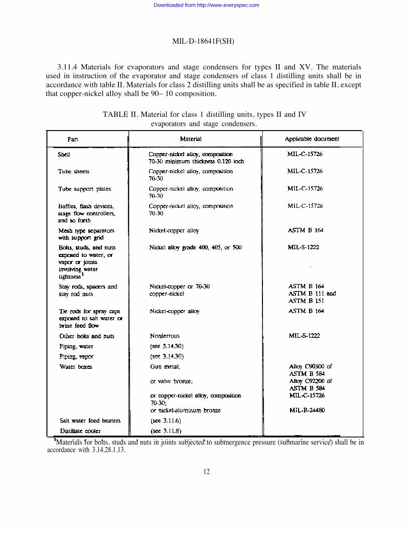
3.11.4 Materials for evaporators and stage condensers for types II and XV. The materialsused in instruction of the evaporator and stage condensers of class 1 distilling units shall be inaccordance with table II. Materials for class 2 distilling units shall be as specified in table II, exceptthat copper-nickel alloy shall be 90– 10 composition.
TABLE II. Material for class 1 distilling units, types II and IVevaporators and stage condensers.
‘Materials for bolts, studs and nuts in joints subjected to submergence pressure (submarine service) shall be inaccordance with 3.14.28.1.13.
12
Downloaded from http://www.everyspec.com

MIL-D-18641F(SH)
TABLE IV. Materials for class 1 distillation units, types II and IVsalt waler feed heaters.
3.11.7 Materials for distiller condensers for types I, III, and V. The materials used in theconstruction of the distiller condenser shall be as shown in table V or class 1. Class 2 materialsshall be the same as for class 1 except that copper-nickel alloy shall be of composition 90-10.
.
14
Downloaded from http://www.everyspec.com

MIL-D-18641F(SH)
3.11.5 Materials for type III evaporators. The materials used in the construction of theevaporators of class 1 distilling units shall be as specified in table III.
TABLE III. Materials for class 1 distillation units, type III evaporator.
3.11.6 Materials for types II and IV salt water feed heaters. The materials for constructionof the salt water feed heater shall be as shown in table IV for class 1 distillation units. Materialsfor salt water feed heaters of class 2 distilling units shall be as shown in table IV, except that allcopper-nickel alloy used shall be 90-10 composition.
.
Downloaded from http://www.everyspec.com

MIL-D-18641F(SH)
TABLE V. Material for class 1 distillation units, types I, III, and V
3.11.8 Materials for distillate coolers, all types. The materials used in the construction of the
distillate coder for class 1 distillation units shall be as show in table VI. Class 2 materials shallbe the same as for class 1 except that copper-nickel alloy shall be composition 90-10.
.
Downloaded from http://www.everyspec.com

MIL-D-18641F(SH)
TABLE VI. Materials for class 1, distillate coolers.
3.11.9 Materials for vapor feed heaters, types I and III. The materials used in theconstruction of the vapor feed heaters of class 1 distillation units shall be as shown in table VII.Class 2 materials shall be the same as for class 1 except that copper-nickel alloy shall becomposition 90-10.
16
Downloaded from http://www.everyspec.com

MIL-D-l8641F(SH)
TABLE VII. Materials for class 1 of types I and III vapor feed heaters.
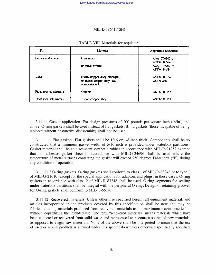
3.11.10 Materials for types I and III tube nest drain regulator and type II salt water feedheater drain regulator. The materials used in the construction of the regulator shall be as shownin table VIII.
17
Downloaded from http://www.everyspec.com
MIL-D-18641F(SH)
TABLE VIII. Materials for regulator.
3.11.11 Gasket application. For design pressures of 200 pounds per square inch (lb/in2) andabove, O-ring gaskets shall be used instead of flat gaskets. Blind gaskets (those incapable of beingreplaced without destructive disassembly) shall not be used.
3.11.11.1 Flat gaskets. Flat gaskets shall be 1/16 or 1/8-inch thick. Components shall be soconstructed that a minimum gasket width of 5/16 inch is provided under waterbox partitions.Gasket material shall be acid resistant synthetic rubber in accordance with MIL-R-21252 exemptthat non-asbestos gasket sheet in accordance with MIL-G-24696 shall be used where thetemperature of metal surfaces contacting the gasket will exceed 250 degrees Fahrenheit (“F’) duringany condition of operation.
3.11.11.2 O-ring gaskets. O-ring gaskets shall conform to class 1 of MIL-R-83248 or to type Iof MIL-G-21610, except for the special applications for adaptors and plugs; in these cases; O-ringgaskets in accordance with class 2 of MIL-R-83248 shall be used. O-ring segments for sealingunder waterbox partitions shall be integral with the peripheral O-ring. Design of retaining groovesfor O-ring gaskets shall conform to MIL-G-5514.
3.11.12 Recovered materials. Unless otherwise specified herein, all equipment material, andarticles incorporated in the products covered by this specification shall be new and may befabricated using materials produced from recovered materials to the maximum extent practicablewithout jeopardizing the intended use. The term “recovered materials” means materials which havebeen collected or recovered from solid waste and reprocessed to become a source of new materials,as opposed to virgin raw materials. None of the above shall be interpreted to mean that the useof used or rebuilt products is allowed under this specification unless otherwise specifically specified.
18
Downloaded from http://www.everyspec.com

3.11.13 Prohibited material. Thetest or inspection of distilling units:
MIL-D-18641F(SH)
following material shall not be used for service, manufacture,
a. Mercury (except fluorescent or mercury vapor lighting)b. Carcinogenic materialsc. Cadmium, magnesium, lead (except for thread lubricant for bolting in joints involving
seawater submarine submergence pressure tightness), or asbestos.
3.12 Operation.
3.12.1 Types I, II, and III. The distillation unit shall use steam at a pressure of 15 (lb/in2)gage or less, to distill to a final vacuum at the air ejector suction of 7-1/2 inches of mercury (Hg)absolute pressure, or less (see 6.2), and shall deliver the distillate at a temperature not exceeding95 ‘F with an initial temperature of seawater of 85 ‘F. For single effect units, the evaporator shellshall operate at a pressure of 11 to 14 inches of mercury absolute to distill seawater.
3.12.2 Type IV. The heat from hot fresh water at specified temperature (see 6.2) shall betransferred to seawater in a feedwater heater. The heated seawater shall then be injected into aflash chamber (or chambers in series) in which part of the seawater is flashed to vapor under avacuum. The vapor shall then be condensed in a condenser.
3.123 Type V. Hot fresh water at specified temperature (see 6.2) shall be circulated througha tube bundle. The tube bundle shall be enclosed in a shell and surrounded by the seawater whichis to be evaporated by transfer of heat from the fresh water. The vapor formal shall be condensedin a distiller condenser.
3.12.4 Types lV and V. Types IV and V shall distill to a final vacuum as required and shalldeliver the distillate at a temperature not exceeding 95 ‘F with85 ‘F.
3.12.5 Temperature In some cases, a higher distillateaccepted (see 6.2).
3.13 Rating. The average production rate shall be not less
an initial seawater temperature of
temperature than 95 ‘F may be
than the rated capacity of the unit(see 6.2) for 24 hours of continuous operation when supplied with seawater between 28 and 85 “Fand with designed brine density as indicated on the heat balance drawing and related technical dataafter 90 days of normal operation. The 90 days of operation shall be as nearly continuous aspracticable. Scale preventive treatment in accordance with DOD-D-24577 may be used duringcapacity tests.
3.13.1 Condition of operation. Unless otherwise specified (see 6.2), the distillation unit shallproduce distillate having a salinity content not exceeding 0.0325 equivalents per million of chlorides(0.125 grain of sea salts per gallon) under all conditions of operation, when evaporating seawater
19
Downloaded from http://www.everyspec.com

MIL-D-18641F(SH)
of not less than 1/32 density (that is: 32 pounds of seawater containing 1 pound of dissolved solids)under the ship motion conditions given in section 301 of DOD-STD-1399 (see 6.2).
3.13.1.1 Orientation. The contractor shall advise the contracting activity if limitations of hisdesign require orientation different from that specified for the distilling unit to meet the require-ments specified herein (see 6.2).
3.13.2 Brine concentration. The distillation unit shall operate with a brine concentration ofone and one-half thirty seconds density or less in the shell of the last evaporator effect or stage.This equates to a minimum seawater feed to distillate produced ratio of 3 to 1.
3.13.3 First stage. In type H distillation units the temperature of the feedwater entering thefirst stage feed inlet compartment shall be limited to between 165 and 175 “F.
3.13.4 Bacteriologically potable distillate. In type I, HI, IV, and V distillation units, provisionshall be made for raising the temperature of the feedwater or distillate to at least 165 “F at somepoint in the cycle to ensure that the distillate is bacteriologically potable when the unit is operatedwith seawater feed considered contaminated, or with brackish feed which may be contaminated, andcarry over of which would not register on the salinity indicators. Water shall not enter the unit ata lower temperature than 165 ‘F subsequent to the point at which the feed has been raised andheld for not less than 7 seconds at that temperature.
3.14 Design. General design shall be as follows (see 6.3 and appendix A):
a. Distillation units shall be of the lightest and most compact construction consistent withreliability.
b. Distillation units shall be constructed and furnished as complete package type units tothe extent that the shipbuilder need only to make external water supply and dischargeconnections, and external steam, air and electrical connections. Pumps, motors andcontrollers, steam pressure reducing valve (if required for proper operation of the unit),water meter, three way dump valve, and salinity indicating equipment shall beconveniently mounted on the unit and piped and wired by the distilling unit manufac-turer. Motor controllers and salinity indicating equipment shall be mounted on a steelpanel or panels l/4-inch minimum thickness. The distiller feed, brine, condensate drain,and distillate pumps may be located separately from the unit in order to permit readyaccessibility for maintenance and to provide a better net positive suction head (NPSH)on the pumps pumping from a vacuum. .
c. On units with mounted electrical equipment, the appropriate components shall becompletely wired in accordance with MIL-E-917 and MIL-C-24643. When required bysuction water level conditions,distilling unit manufacturer for
circulating and feed pumps shall be furnished by theseparate mounting by the shipbuilder (see 6.2).
.
20
Downloaded from http://www.everyspec.com

MIL-D-18641F(SH)
d. The distilling unit manufacturer shall furnish pumps of adequate capacity for thevarious services, with discharge pumping heads as determined by the shipbuilder(see 6.2), and with adequate motor horsepower as determined by these conditions.
e. Feed for types I and III distilling units shall be furnished normally under sufficientpressure from the distiller condenser circulating system by means of a back pressurevalve in the overboard discharge line, the valve to be furnished by the shipbuilder. Inthe case of multi-effect units, in which this would require excessive circulating pumppower, a separate feed pump shall be furnished (see 6.2).
f. Feed and circulating pumps shall be in accordance with MIL-P-17840 or MIL-P-17639where these pumps are not covered in the rating charts of MIL-P-17840. Distillate,brine, and condensate pumps shall be in accordance with MIL-P-18472, except that thebrine pump shall have mechanical seals in accordance with MIL-P-17639. The distillateand condensate pumps shall be furnished with stuffing box packing. Sealing water shallbe supplied from the discharge piping except for the brine overboard pump which shallbe supplied from the feed or circulating pump discharge. Individual motor driven pumpunits are required (double ended motor pump units are not permitted). Salinityindicating equipment shall be in accordance with MIL-S-5103. Steam pressure reducingvalve shall be in accordance with MIL-V-18030. Each steam pressure regulating valveshall be supplied with isolation valves and by-pass the throttling valve, Y-strainer andsupply and discharge pressure gauges. When specified (see 6.2), a water operatedeductor shall be provided in lieu of a brine overboard pump.
g. A drain regulator (see 3.22) or other type of automatic level controller shall befurnished for any component of the distillation unit fresh water system wherein aspecific water level must be maintained to permit operation of the unit.
h. When necessary (such as in submarine installation in which the seawater temperaturevaries rapidly when the depth of submergence changes), a thermostatically controlledvalve shall be provided either in the outlet circulating water line from the distillercondenser or to bleed air into the condenser, so as to prevent sudden changes invacuum and consequent unbalanced operation which will result in carry-over of saltwater from the evaporator to the distiller condenser.
i. Cleanout openings or flanges shall be provided as required to enable manual cleaningout of accumulated scale, mud or sand from any location in which such accumulation,after any length of time, will interfere with the proper operation of the unit. Examplesare:
(1) Seal pipes between effects or stages which may become clogged with flakes of scaleor with mud or sand which may accumulate.
21
Downloaded from http://www.everyspec.com

MIL-D-18641F(SH)
(2) Chambers in which orifices are installed for injection of feed into the evaporatingsection. (Dislodged scale or debris may accumulate and clog the orifices.)
3.14.1 Type I. A type I distillation unit shall consist of one or more evaporating effectscomposed of a shell or shells in which horizontal, straight or U-bent tube bundles are submergedin the salt water to be evaporated and supplied with heating steam or vapor inside the tubes, adistiller condenser, distillate cooler if necessary, air ejectors and after-condenser, vapor feed heatersif necessary, integral piping, valves and fittings, thermometers, gauges, flash tank drain regulators,meters, pumps, motors, controllers, and salinity indicating equipment.
3.14.2 Type II. A type II distillation unit shall consist of one or more evaporating stages ina single or multiple shell, a salt water feed heater, distillate cooler if necessary,air ejectors, aftercondenser, integral piping, valves and fittings, thermometers, gauges, drain regulators, meters,pumps, motors, controllers, and salinity indicating equipment. Each stage shall be equipped witha feed inlet with means for introducing the feed into the evaporator shell in proper form for mosteffective flashing of part of the water into vapor, necessary baffles and a vapor separator toprevent carry over of salt water, and a stage condenser to condense the vapor so flashed.
3.143 Type III. A type III distillation unit shall consist of one or more evaporating effects,each composed of a vertical, corrugated basket or multiple baskets surrounded by a shell, in whichthe salt water to be evaporated is contained between the shell and basket corrugations and theheating steam or vapor is contained inside the corrugated basket, a distiller condenser, distillatecooler if necessary, air ejector and after condenser, vapor feed heaters if necessary, integral piping,valves and fittings, thermometers, gauges, flash tank drain regulators, meters,, pumps, motors,controllers, and salinity indicating equipment.
3.14.4 Type IV. A type IV distillation unit shall consist of one or more evaporating stages ina single or in multiple shells, a salt water feed heater for transferring heat from the hot fresh waterto the sea water, distillate cooler if necessary, air ejector, after condenser or vacuum pump (see6.2), integral piping, valves and fittings, thermometers, gauges, drain regulators, meters, pumps,motors, controllers, and salinity indicating equipment. Each stage shall be equipped with a feedinlet with means for introducing the feed into the evaporator shell in proper form for mosteffective flashing of part of the water into vapor, necessary baffles and a vapor separator toprevent carry-over of salt water, and a stage condenser to condense the vapor so flashed.
3.14.5 Type V. A type V distillation unit shall consist of one or more evaporating effectscomprised of an evaporator shell or shells in which a tube bundle is submerged in the salt waterto be evaporated and the hot fresh water is circulated through the tubes. The remaining com-ponents shall consist of a mesh vapor separator, a distiller condenser, air, sea water, brine anddistillate pumps or eductors, distillate coder if necessary; valves, fittings, thermometers, gauges,drain regulators, meters, pump motors and controllers, and salinity indicating equipment.
3.14.6 Supports. Supporting feet or brackets shall secure the unit, its components oraccessories adequately against high impact shock or when the ship is listed, pitching, or rolling(see 3.13.1). Components shall not be supported by plates or brackets in such manner that the
22
Downloaded from http://www.everyspec.com

MIL-D-18641F(SH)
primary means of support is the clamping action of the bolts securing the shell end flange-tubesheet-water box flange joints of the components, nor shall nozzle flanges or piping constitute theprimary means of support of components or accessories.
3.14.6.1 Shock resistance
3.14.62 Bolts. Bolts to be stressed in shear shall be installed in holes not greater than thefollowing sizes:
Nominal bolt diameter Maximum diameter of holeinch inch
3/4 and smaller Nominal bolt diameterLarger than 3/4 Nominal bolt diameter
3.14.63 Rigid supports. Units that arc rigidly supported shall notstructures which can deflect relative to each other under shock loadings.
3.14.6.4 Shock mountings. Shock mountings shall not be used withoutNAVSEA
3.14.63 Braces. Where braces must be employed to afford stability under
plus 1/32plus 1/16
be attached to two
prior approval from
vibration, the bracesshall be constructed to fail under a load caused by a force equal to five times the weight of theunit. This bad shall be acting at the center of gravity of the unit.
3.14.6.6 Snubbers. Where snubbers must be employed to limit deflection under shock loading,the snubber shall be constructed in accordance with NAVSEA 0908-LP-000-3010.
3.14.697 Locking devices. The use of spring lock washers is not permitted. Acceptable lockingdevices are self locking nuts in accordance with MS 17828, lock tab washers in accordance withMS 18288 or lockwire.
3.14.7 Piping connections. Connection flanges (see 6.2) shall be in accordance with theapplicable schedule of MIL-STD-777 for surface ships or MIL-STD-438 for submarines asappropriate. Root connections shall be in accordance with Drawing B 214. In lieu of instructionshown on Drawing B 214, nozzles may be fabricated from short lengths to pipe provided with aslip-on flange welded to one end, and pads shall be bar stock or plate of requisite thickness forstuds. Nozzles shall be of the minimum length possible for installation or removal of through bolts,
3.14.7.1 Alternate flange construction. For surface ships, the main flanges of nonferrousfabricated water boxes or shells, the flanges of waterbox and shell nozzles, and the flanges of accessopenings when provided with a neck may be of steel in accordance with ASTM A 285, grade C.When the use of steel flanges is elected, they shall be constructed to ensure that the steel cannotcome in contact with seawater. This shall be accomplished by lining the steel flange to a depth of
23
Downloaded from http://www.everyspec.com

MIL-D-18641F(SH)
not less than 3/16 inch thick with nickel-copper alloy or 70-30 copper-nickel alloy in accordancewith MIL-E-22200 and MIL-E-22200/4 or type MIL-EN67 of MIL-E-21562, or nickel-copper alloyin accordance with MIL-9N10 of MIL-E-22200 and MIL-E-2200/3 or types MIL-RN60 orMIL-EN60 of MIL-E-21562. On the face of the flange this protection shall extend from the boreto at least the inner edge of the bolt holes. The 3/16 inch thickness of the protecting alloy is theminimum required after final machining of the flange. Inlay thickness shall be verified afterdepositing (allowance for machining shall be provided) and, after final machining of the flange.
3.14.8 Waterboxes. Components of the distillation unit which require salt water circulationthrough the tubes shall be provided with waterboxes so proportioned as to provide sufficient areaat all points for flow of the circulating water with a minimum of turbulence, and for uniformdistribution of the water to all tubes in each pass. Single pass components shall have an inletwaterbox depth measured normal to the tube sheet at the center of not less than one-half thediameter of the tube sheet exposed to circulating water flow. Multi-pass components shall havewaterboxes so constructed that the depth at each inlet pass, at the center thereof, shall be not lessthan one-half of the diameter of a circle of area equivalent to that portion of the tube sheetexposed to inlet circulating water flow. Waterboxes shall be provided with adequate vents, includingvent holes in the partitions between passage and with drains as necessary.
3.14.9 Flow velocity limits. The velocity of flow of circulating water or feed entering the inletnozzles of the distillate coder, distiller or stage condensers, air ejector pre-cooler and after-condenser, and vapor or salt water feed heaters shall not exceed 7.5 feet per second average underthe rated conditions. Salt water feed heaters of type II units using recirculated brine may bedesigned for an average velocity through the tubes of 8 feet per second. If divergent nozzles areprovided, this velocity shall not be exceeded at the actual entrance of the water into the waterbox.
3.14.10 Salt water feed beating. In types I and III, provision for heating the salt water feedshall be made by segregation of a section of the distiller condenser tubes, circulation of thefeedwater through the ejector after condenser, and provision of a vapor feed heater for eachevaporator effect except the last, the feedwater being circuited through these components inseries. The foregoing series may be varied as best suits the design of the unit for operation withvarying water temperatures. In types 11 and IV, provision for heating the sea water feed shall bemade by circulation of the feedwater through the distillate cooler, the stage condensers, the ejectorafter condenser, and the salt water feed heater in series.
3.14.11 Installation of salinity cells. Provision shall be made as applicable in the integralpiping or drain regulators for installation of salinity cells in the fresh water drains from eachcomponent of the distillation unit in which salt water leakage may contaminate the condensate ordistillate. The salinity cells shall be so oriented as to be submerged in water under any conditionof operation. Cells associated with dump valve operations shall be located a sufficient distanceupstream of the valve to prevent passage through the valve of any contamination sensed by thesalinity cell.
24
Downloaded from http://www.everyspec.com

MIL-D-18641F(SH)
3.14.12 Dump valve. A three-way solenoid operated distillate dump valve, the solenoid beingactuated by the salinity cell located in the line provided for final delivery of distillate (after all heatexchangers), shall be provided with the distillationMIL-V-16556.
3.14.12.1 Type III. An additional solenoidMIL-V-16556, actuated by the salinity cell located in
unit. The valve shall be in accordance with
operated dump valve, in accordance withthe air ejector after condenser drain line shall
be provided with type 111 distillation units using vertical distiller condensers unless the air offtakethereof and the air ejector are so located that there is no possibility of carry-over of saltcontaminated distillate into the after condenser.
3.14.12.2 Type II. On type II distillation units, a three-way solenoid-operated dump valve inaccordance with MIL-V-16556, actuated by a salinity cell located in the drain line from the saltwater feed heater, shall be installed in the salt water feed heater drain line. The drain line fromthe air ejector after condenser shall connect to the salt water feed heater hotwell through a loopseal.
3.14.13 Tubes. Tubes in the evaporators, vapor feed heaters, distiller condenser, stagecondensers, salt water feed heaters, and distillate coder shall be composition 90-10 in class 2distillation units, or composition 70-30 in class 1 distillation units, in accordance with MIL-T-15005.Tubes shall normally be 5/8 inch outside diameter (od), number 18 Birmingham wire gauge (BWG)(0.049 inch wall thickness). In small capacity units of up to 5,000 gallons per day of distillate, whenthe use of smaller diameter tubes will result in fewer passes in the above heat exhangers, the tubesmay be 3/8 inch od, number 18 BWG. In some submarine usage, the tubes may be requiredthicker than number 18 BWG (see 6.2).
3.14.13.1 U-bent tubes. When U-bent tubes are allowed (see 3.15.2, 3.16.1, 3.19.1, 3.20.1,3.21.1), the minimum radius of the U-bend shall be 5/8 inch for 3/8 inch od tubes, 15/16 inch for5/8 inch od tubes, and 1-1/8 inch for 3/4 inch od tubes.
3.14.13.l.1 Expansion of tubes. Tubes shall be expanded at each end into the tube sheets bymeans of an automatic tube expander control and with tube expanders in accordance withMIL-E-15809. The tube expander shall be adjusted so that expansion of the tube is stopped within1/8 inch of the inner face of the tube sheet. In double tube sheet heat exchangers, the expansionof the tubes in the inner tube sheet shall not start closer than 1/8 inch from the outer face of thattube sheet and shall stop within 1/8 inch of the inner face. Care shall be taken that there is noabrupt change in contour of the inner tube surface caused by the expanding operation. Theexpander shall be set such that a wall reduction of approximately 10 percent is attained. .
3.14.14 Tube sheet drilling. The holes for 3/8 inch od tubes shall be reamed to 0.376 inchdiameter with a plus tolerance of 0.005 inch. The holes for 5/8 inch od tubes shall be reamed to0.626 inch diameter with a plus tolerance of 0.005 inch- The holes for 3/4 inch od tubes shall bereamed to 0.751 inch diameter with a plus tolerance of 0.005 inch. The holes for the inlet ends ofthe tubes shall be flared on a radius of 5/16 inch for 3/8 inch od tubes, 1/2 inch for 5/8 inch od
25
— . . . . .
Downloaded from http://www.everyspec.com

MIL-D-18641F(SH)
tubes and 3/4 inch od tubes, to a diameter at the outer face of the tube sheet ofinch od tubes, 3/4 inch for 5/8 inch od tubes, and 7/8 inch for 3/4 inch od tubes.
1/2 inch for 3/8
3.14.15 Tube sheet thickness. The minimum acceptable tube sheet thickness shall be 3/4 inchfor 5/8 inch od tubes and 5/8 inch for 3/8 inch od tubes. (For 3/4 inch od tubes see 3.18.1.3.)
3.14.16 Tube spacing. The minimum acceptable tube spacing shall be 13/16 inch, center-to-center for 5/8 inch od tubes and 17/32 inch for 3/8 inch od tubes (For 3/4 inch od tubes see3.18.1.4.)
3.14.17 Support plates. Tubes of 3/8 inch and 5/8 inch od shall be supported by tube supportplates so that the maximum span between tube sheet and support plates or between support plateswill not exceed 2 feet and 3 feet respectively. If the construction is such that the cross-flow bafflesdrilled for the tubes are installed between the tube sheet and support plates and between supportplates, the thickness of the support plates and baffles shall be not less than 1/4 inch. If such cross-flow baffles are not installed, the support plates shall be not less than 9/16 inch thick. Holes fortubes in support plates shall be drilled not more than 1/64 inch diameter larger than the nominaloutside tube diameter. Holes for tubes shall be rounded on each face of the support plate to a1/16 inch radius. Holes in cross-flow baffles shall have sharp edges removed (For 3/4 inch od tubessee 3.18.1.5.)
3.14.18 Shell expansion. Provision shall be made for expansion and contraction of the shellof shell and tube type heat exchanger components ofshell expansion and contraction are:
a. One support shall be constructed to flexdrilled as specified in 3.14.6.2
b. Both supports shall be rigid. One support
distillation units. Acceptable provisions for
and the other support shall be rigid, both
shall be provided with slotted holes for thefoundation bolts. A bushing shall be provided around the foundation bolt, sodimensioned that the bolt head is prevented from binding the support when the nutis tightened. Clearance between a shoulder on the bushing and a machined or spot-faced surface surrounding the bolt hole shall not exceed 0.005 inch, in order tominimize impact on the foundation bolt under high impact shock load. Total clearancesof the inside diameter of the bushing over the nominal bolt diameter and the width ofthe slotted hole in the support over the od of the bushing shall not exceed thosespecified in 3.14.6.2 The other support shall be drilled as specified in 3.14.6.2
c. When U-bent tubes are used, an expansion joint shall be provided in the shell betweentwo rigid supports.
d. When one support constructed to flex is used, the rigid support shall be constructedto withstand the entire high impact shock load in the direction longitudinal of the heatexchanger. When a shell expansion joint is heated between two rigid supports, eachsupport shall be constructed to withstand the high impact shock load equivalent to the
26
Downloaded from http://www.everyspec.com

weight of theshell between
MIL-D-18641F(SH)
tube bundle plus that of the adjacent water box and that portion of thethe expansion joint and the shell end flange adjacent to the support, in
the direction longitudinal of the heat exchanger.
3.14.l8.l Unrestrained expansion and contraction. Provision for unrestrained expansion andcontraction of the tubes of all shell and straight tube type heat exchanger components of thedistillation unit shall be made by use of an expansion joint in the shell, located between onesupporting foot and the shell end flange, or by use of floating head instruction- In the case ofheat exchangers with an odd number of passes, restraint of tube expansion and contraction shallbe avoided by providing an expansion joint in the piping connected to the water box adjacent tothe shell expansion joint or the floating head. If the piping is integral with the distillation unit, theexpansion joint shall be provided with the piping.
3.14.19 Component removal provisions. Adequate guides, slides, lifting lugs, and accessopenings shall be provided to facilitate removal of the evaporator tube nests or baskets, meshvapor separators, stage condenser tube bundle and vapor feed heater tube nests from the shellsand for handling the water boxes of the distiller condenser, stage condensers, salt water feed heaterand the distillate cooler.
3.14.20 Jack screws. Jack screws shall be provided in all flanges ofbe disassembled for maintenance. Jack screws are not required for flangedO-ring face seals.
3.14-21 Bolts or stud bolts. The water box flange, tube sheet andcomponents shall be secured by through bolts or stud bolts. Studs shall
flanged joints that mustjoints which incorporate
shell flange joints of allnot be used unless it is
impracticable to use through or stud bolts. If through bobs are used, alternate bolts shall be collarbolts; if stud bolts are used they shall be driven into tapped holes in the tube sheets, so that thejoint between the tube sheet and shell flange will not be broken when the water boxes areremoved. Collar bobs shall be replaceable without removing the water boxes. Collar and stud boltsshall be provided with one square end for use of a wrench to prevent turning when the nut at thewater box flange end is removed.
3.14022 Sight glass. Sight glass assemblies, if glass is used, shall be composed of a metalflanged frame to be bolted to a boss or flange on the evaporator shell. The flame shall contain thesight glass. The glass shall be secured with gaskets by means of a ring screwed into the flame soas to obtain even pressure on the glass, and so that the pressure on the glass is not changed whenthe sight glass frame assembly is removed from the evaporator shell. Jack screws shall be providedin the flange of the frame. Glasses shall be in accordance with MIL-G-2860.
3.14.22.1 Plastics acrylic sight glass assemblies. The use of plastic acrylic heat resistant sheet.
shall be limited to applications having service temperatures below 150 “F. Sight glass assemblies,if plastic acrylic heat resistant sheet is used in lieu of glass, shall be a single flange, bolted to theface of a pad or flange on the evaporator shell, securing the plastic sheet thereto between resilientgaskets. The flange shall be provided with jack screws. The plastic sheet shall be finish A inaccordance with MIL-P-5425 and shall be of suitable thickness for the intended service.
27
Downloaded from http://www.everyspec.com

MIL-D-18641F(SH)
3.14.23 Vents and drains. Vents and drains shall be provided in each component as required.Low points in integral piping which will not drain when the distillation unit is shut down shall beprovided with a plugged drain so that they may be drained when the ship is secured and unheated.
3.14.24 Cathodic protection Readily replaceable zinc anodes in accordance with MIL-A-19521shall be installed in the salt water circuits of all heat exchangers of the distillation units except theevaporating shells in accordance with the following:
a. For submarine submergence pressure applications, threaded support plugs shall not beused. Cover plates secured by four or more threaded fasteners shall be used for supportof anodes.
b. For submarine non-submergence pressure applications, bolted rover plates or threadedplugs shall be used for support of anodes. If used, threaded plugs shall conform toDrawing 803-5959186.
c. For surface ship applications, support plugs shall be of the straight thread O-ring sealtype in accordance with MIL-A-19521. In exception to the material requirements ofMIL-A-19521, plug materials shall conform to the following:
Nickel-copper alloy QQ-N-281 or ASTM B 16470-30 Copper-nickel alloy MIL-C-15726 or alloy 715 of ASTM B 151
3.14.25 Air ejector assemblies. The air ejector assembly furnished with the distillation unitshall conform to type II of MIL-E-15465. The class shall be the same as specified for thedistillation unit, except for saturated steam propelled ships the air ejector assemblies shall beclass 3. Only one air ejector is required. Furnishing of a single or two stage air ejector unit shallbe determined by the distillation unit manufacturer as best fitting the vacuum requirements of thedistillation unit. A two stage air ejector shall be of the type which does not require an inter-condenser. The air ejector steam pressure and temperature shall be as specified (see 6.2).
3.14.25.1 Oversized air ejectors. Oversized air ejectors and their after condenser shall not beprovided for the purpose of obtaining extra feed heating by using the high pressure air ejectormotive steam and thus decreasing the number of stages or effects or the size of the evaporatorsor the salt water heater which uses low pressure auxiliary exhaust steam.
3.14.25.2 Check valve A check valve shall be provided in the air off-take line between thedistiller or stage condenser and the air inlet of the air ejector, or at the discharge of the airejector, to prevent loss of vacuum in the condenser due to sudden fluctuations in the steam supplyto the air ejector.
3.14253 Nozzles. Nozzles for units constructed with multi-stage air ejectors shall not beinterchangeable.
28
Downloaded from http://www.everyspec.com

MIL-D-18641F(SH)
3.14.25.4 Steam chests. Air ejector steam chests for all units shall be manufactured of a 400series stainless steel.
3.1425.5 Test orifice A test orifice connection with orifice plate and cut-out valve shall beinstalled in the air ejector suction piping. The test orifice connection shall be installed downstreamof the cut-out valve to allow a metered amount of air to the air ejector suction to check air ejectorperformance.
3.14.26 Vacuum pump. When specified (see 6.2), the vacuum pump for types IV and Vdistilling units shall be in accordance with MIL-V-18683. Pumps shall be single or multiple stageas required by vacuum conditions.
3.14.26.1 Eductor. In lieu of the vacuum pump specified in 3.14.26, a water operated eductormay be furnished. Materials shall be nickel-copper alloy for the eductor nozzle and bronze inaccordance with ASTM B 61 for the eductor body.
3.14.27 Flow meters. Flow meters shall be provided for each type I, III, or V distillation unit.Meters for flow of feed or brine shall be of a construction which is not readily affected by scaleformation. In particular, meters equipped with a guide rod on which the float rides, or with anindicating rod mounted on the float and extending through a guide or packing gland are not accep-table. If method of feed is such that the ratio of feed and distillate must be controlled feed anddistillate meters shall be provided; otherwise, only a feed meter will be required.
3.14.27.1 Water meter. A distillate water meter shall be provided with each unit. Meter shallconform to class B in accordance with MIL-M-2082, except that a magnetic drive shall be provided.
3.14.28 Distilling units for saturated steam propelled surface ships and submarines.
3.14.28.1 Submergence pressure. In submarines, the feed for the distilling unit will be reducedfrom submergence pressure to that required by the feed circuit of the unit by means of a pressurereducing valve furnished by the shipbuilder who will also furnish a relief valve to safeguard againstmalfunction of the reducing valve. Any parts of the distilling unit located ahead of the reducingvalve and thus subjected to submergence pressure shall be constructed to withstand this pressure.
3.14.28.1.1 Heat exchangers. Heat exchangers of the shell and tube type provided ascomponents of the distillation unit for saturated steam propelled surface ships or submarines shallbe provided with two tube sheets at each end, except when U-bent tubes are used, two tube sheetsshall be used at the inlet-outlet end. For straight tube bundle exchangers, the inner tube sheetsshall be welded to the shell. A space not less than 1/2 inch wide shall be provided between thetube sheets by use of a spacer ring or by machining one face of one or both tube sheets. Thespace shall be provided with a vent and drain to atmosphere. The joint between tube sheets orbetween tube sheet and spacer shall be welded. The contractor shall be responsible for providingthe proper span of tubes between double tube sheets, so that the tubes will not be overstresseddue to radial expansion differentials of the double tube sheets (see 6.3 and appendix C).
29
Downloaded from http://www.everyspec.com

MIL-D-18641F(SH)
3.14.28.1.1.1 Tube sheet tube holes. For submarines, in heat exchangers subjected tosubmergence pressure, the tube sheet shall be drilled as specified in 3.14.14 or 3.18.12, except thatthe holes for 3/8 inch, 5/8 inch or 3/4 inch od tubes in the outer tube sheets shall have threegrooves 1/8 inch wide and 0.012 inch deep, located 1/8 inch apart, and the holes for 3/8 inch,5/8 inch or 3/4 inch od tubes in the inner tube sheets shall have two grooves 1/8 inch wide and0.012 inch deep, located 1/8 inch apart. In heat exchangers not subjected to submergence pressurein submarines and in those for saturated steam propelled surface ships, the tube sheets shall bedrilled as specified in 3.14.14 or 3.18.1.2 except that the inner tube sheet holes shall have onegroove 1/8 inch wide and 0.012 inch deep.
3.14.28.1.1.2 Tube expansion. Tubes shall be expanded into both inner and outer tube sheetsat each end specified in 3.14.13.1.1. Minimum depth of expansion in the inner tube sheet shall be1/2 inch for 3/8 inch od tubes, 5/8 inch for 5/8 inch cd tubes and 3/4 inch for 3/4 inch od tubes,The expander shall be set such that a wall reduction of approximately 10 percent is attained. Afterexpansion of the tube ends, the specified water side hydrostatic test pressure shall be applied tothe spaces between the double tube sheets (see 4.3.1.1).
3.14.28.1.1.3 Water box flanges. The water boxes shall have either internal or external flanges.Internal water box flanges shall be studded, with nuts on the shell side of the inner tube sheet, andguide pins longer than the studs and inserted in holes having smaller diametrical clearance than theholes for the studs shall be provided to prevent damage to the threads on the studs when thewater boxes are installed. Through bolts shall be used with external water box flanges.
3.14.28 .1.1.4 Parts subjected to submergence pressure Parts subjected ‘to submergencepressure including structure composed of outer and inner tube sheets together with short sectionsof tubes between paired inner and outer tube sheets, shall be constructed in accordance with therequirements of the ASME Boiler and Pressure Vessel Code, Section III, Nuclear Power PlantComponents, class 1 components, as a minimum, except welding shall be in accordance withMIL-STD-278. Reinforcement of openings shall be integral with the water box shell or nozzle (orboth). Separate pads or saddle type reinforcements shall not be used. Welds shall be groundsmooth and the comers and fillets shall be well rounded as necessary to minimize notch effect.In the design of heat exchangers, the forces exerted by the circulating water inlet and dischargepiping on the respective water box nozzles shall be as follows:
30
Downloaded from http://www.everyspec.com

MIL-D-18641F(SH)
3.14.28 .1.1.4.1 Force loading. In the design of heat exchanger salt water sides, fullconsideration shall be given to the cyclic nature of the pressure and external force loading. Thedesign shall be based on the number of total depth changing cycles specified in NAVSEAT9070-AA-DDT-010/(C) SUBS, with associated temperature variation in conjunction with thatpiping reaction load (see 3. 14.28.l.l.4) that produces the highest stress, 8,000 cycles of start up andshut down, 200 cycles each of the specified hydrostatic test pressure when applied in the water boxor between the double tube sheets and 300 cycles of loss of seawater (see 6.3 and appendix C).The analysis shall be in accordance with the methods and criteria of ASME Boiler and PressureVessel Code, section III, division 1, class 1 components. Design fatigue curves for materialscommonly used in distillation units and design stress intensity values for materials not covered insection III (class 1 components) of ASME code shall be obtained from NAVSEA or the purchaser.Method of analysis of flat perforated plates shall be in accordance with Article A-8000, of SectionIII of ASME Code, division 1, appendices. Cumulative usage factor for all cyclic transients shallnot exceed 0.8.
3.14.28.1.1.4.2 Submergence pressure Heat exchangers subjected to submergence pressure shallhave an even number of salt water passes, so that the inlet and outlet salt water nozzles will beon the same water box. Thus the stiffness of the piping will not affect expansion or contractionof the heat exchanger tubes.
3.14.28.l.l.5 Bolts and studs composition Bolts and studs subjected to submergence pressureshall be nickel-copper alloy in accordance with QQ-N-281, class A, hot finished; or nickel-copperalloy in accordance with MIL-N-24106, cold drawn, and stress relieved or hot finished; or nickel-copper-aluminum alloy in accordance with QQ-N-286, class A, hot finished, annealed and agehardened or cold drawn, annealed and age hardened. Nuts for these bolts and studs shall be nickel-copper alloy in accordance with QQ-N-281, class A or B, hot finished condition; or nickel copperalloy in accordance with MIL-N-24106, cold drawn and stress relieved or hot finished; or nickel-copper alloy in accordance with ASTM B 164, hot finished. Nickel-copper-aluminim alloy bolts andstuds shall also conform to
a. Calculated boltstrength of the
MS 18116. ,
stress due to design pressure shall be limited to one-third of the yieldmaterial at the design temperature.
b. Maximum value of service stress average across bolt cross-section and neglecting stressconcentration factor shall be limited to two-thirds of the yield strength of the materialat the design temperature.
31
Downloaded from http://www.everyspec.com

MIL-D-18641F(SH)
c. Maximum value of service stress at periphery of the bolt cross-section resulting fromtension plus bending neglecting stress concentration factor shallstrength of the material at the design temperature.
d. Threaded fasteners with torque requirements shall be lubricatedmineral oil per MIL-L-24479.
e. The range of inefficient of friction for the lubricant shalldetermining torque value as follows:
(1) Using the hydrostatic test load or the load bawl on
be limited to the yield
with red-lead-graphite
be accounted for in
design pressure plusmaximum piping load on nozzles, whichever is greater, and high coefficient offriction @ = 0.13), determine torque using the following equation:
(2) Using the installation torque above and low coefficient of friction @ = 0.065),determine stress from the following equation:
P in this equation is the preload force in pounds, using the low coefficient offriction (0.065) and the installation torque calculated above. This calculated
stress when combined with other stresses specified in ASME shall not exceed the limits of ASMEBoiler and Pressure Vessel Code, section III.
f. Fatigue analysis of bolts shall be in accordance with section III, division 1, subsectionNB, class 1 of ASME Boiler and Pressure Vessel Code, except that cumulative usagefactor shall not exceed 0.8.
32
Downloaded from http://www.everyspec.com

MIL-D-18641F(SH)
g. Submergence pressure boundary studs and bolts shall be of a reduced shank design toreduce bending stresses.
3.14.281.1.5.1 Inspection openings. Threaded fasteners securing water box inspection openingsin submarine distilling plant heat exchangers subjected to submergence pressure shall be designedsuch that 200 inspection cover removal and reinstallation cycles and the cycles specified in3.14.28.1.1.4.1, will not cause the maximum cumulative usage factor to exceed 0.8. The effect onthreaded fastener stress levels caused by any movement between the inspection rover andinspection cover flange when the seawater side of the water box is pressurized shall be specificallyanalyzed. The amount of movement or relative slip used in above analysis shall be confirmedduring factory hydrostatic testing of first unit (see 4.3.1.1). The measured amount of relative slipshall be compared to the assumed value. The fastener shall meet the requirements of ASMEBoiler and Pressure Vessel Code, section III, division 1, subsection NB, class 1 components whenthe measured slip (rather than the assumed slip) is factored into the analysis.
3.14.28.1.1.6 Operation. Distillation units for submarines shall operate at an ambient pressureof 30 inches of Hg absolute with a variable of plus or minus 6 inches Hg and shall not be damagedwhen subjected to an ambient absolute pressure between 10 and 30 lb/inz with the minimuminternal pressure which will prevail under any condition of operation.
3.14928,2 Shutdown. Distilling units on saturated steam propelled surface ships and submarinesshall accommodate a one-button shutdown of the unit which will safely secure all steam, sea waterfeed and brine dilution, trip all solenoid operated dump valves and secure all distilling plant pumps.The one-button shutdown system will be provided by the shipbuilder.
3.14.283 Heating steam circuit For distilling units on saturated steam propelled surface ships,the heating steam circuit of the salt water feed heater shall be vented to atmosphere only. Thevent piping shall contain an orifice sized for normal operation. A bypass with globe valve shall beprovided around the orifice for use during start up.
3.14.29 Acid cleaning connections. Connections, with hose-gate valves, complete with chainand cap shall be provided in the integral piping of the unit, if feasible, or in shipbuilder furnishedexternal piping, for introduction, circulation and discharge of acid solution for chemically cleaningthe distilling unit. Type II units shall have the feedwater piping so arranged that reducing flangeswith 1 inch nominal pipe size nipples (to be furnished with the unit) may be installed to permitthe salt water heater, the air ejector after condenser and the stage condensers to be individuallychemically cleaned .
3.1430 Piping. Integral piping, valves, fittings and similar items shall be in accordance withMIL-STD-777 or MIL-STD-438 as applicable Seawater feed control valves for Types II and IVdistilling plants shall be in accordance with MIL-V-18030 or Drawing 803-1385S41 except that valvebody, seat and disc material shall be nickel copper alloy.
I
33
Downloaded from http://www.everyspec.com

MIL-D-18641F(SH)
3.1431 Scale preventive compound Connections shall be provided for introduction of scaleprevention compound into the salt water feed stream.
3.14.32 Proportioning pump. A proportioning pump and supply tank, in accordance withMIL-P-21397, shall be furnished for introduction of the scale preventive compound.
3.14.32.1 _Flow meter. A flow meter of design, materials, and measurement range for usc with. . .either feed treatment addition or on-line citric acid cleaning, shall be furnished.
3.15 Evaporators for type I, submerged tube type low pressure steam operated or type V heatreovery units.
3.15.1 Cleaning and descaling. The tubes and tube nests shall be arranged as to be readilyremovable and easily accessible for cleaning, descaling and repairs; and so that cleaning anddescaling can be accomplished with the removal of the least possible number of fittings andconnections.
3.15.2 Tubes. Two steam passes (type 1) or water passes (type V) shall be provided, Thetubes shall be so arranged that none of the heating surfaces will be exposed above the normalworking water level. The evaporator tubes may be straight and expanded into tube sheets at eachend or may be U-bent tubes expanded into an inlet/outlet tube sheet.
3.15.3 Scale preventive compound. The piping system of the distilling unit shall be providedwith a connection for injection of a scale preventing compound, so located that the compound willpass through the tubes of all salt water feed heaters and all of the compound will pass into thefirst effect evaporator shell with the feed.
3.15.4 Sump space An adequate sump space underneath the tubes shall be provided for scaleto lodge. A flat removable rover shall be provided so that the sump may be cleaned withoutremoving the tube nest.
3.15.5 Baffles. Baffles for suppression of wash and for moisture separation shall be fittedover the tube nest as necessary to meet the requirements of 3.13.1.
3.15.6 Heating surface The ratio of heating surface of tubes to the disengaging surface (watersurface) shall not exceed 14.5 (type I).
3.15.7 Shell. The shell of each evaporator effect shall be fitted with two sight glasses locatedjust above the working water level.
3.15.8 Air vents and valves Each tube nest shall be provided with adequate air vents, andvalves shall be provided for regulation thereof.
3.15.9 Strainers. Strainers shall be provided in the evaporator shells or in the integral pipingof the distillation unit for the brine overboard pump suction and for the evaporator feed betweeneffects. Access shall be provided for cleaning any strainer installed inside the shell.
34
Downloaded from http://www.everyspec.com

MIL-D-l864IF(SH)
3.5.10 Level controls. Adjustable or fixed weir type level controls shall be provided formaintaining a constant level of brine in each effect.
3.15.11 Evaporator. The following connections and fittings shall be provided for eachevaporator:
a. Evaporator shells: (minimum thickness 0.120 inch)
(1)(2)(3)(4)
(5)(6)(7)(8)(9)(l0)(11)
Feed inlet connectionBrine outlet connectionCompound pressure and vacuum gauge, 4-1/2 inch diameterWater gauge glass, with mark showing top of the tubes. When weir levelcontrols are provided, gauge glasses shall be located thereon.Relief valve (first effect only)Vapor discharge connectionSump with removal plate for cleaningFoundation fittings and necessary attachments for anti-rolling braces, where fittedDrain from vapor separator if external separator is providedSight glassesAir vent from brine pump in last effect shell only.
b. Evaporator steam heads
(1) Steam supply connections(2) Drain connection(3) Air vent connections(4) Relief valve (first effect only)(5) Gauge glass; except when drain regulators are provided, the gauge glass shall
be located thereon(6) Compound pressure and vacuum gauge, 4-1/2 inch diameter(7) Thermometer(8) Lifting and handling eyebolts or lugs.
3.15.12 Orifice plate One orifice plate with proper size orifice shall be provided with thetype I distillation unit for the steam supply to the fret-effect steam chest to limit the steam flowto that specified for rated capacity. Orifice plate shall be provided with a tab for pulling and shallbe stamped with the orifice size and manufacturer’s part number.
3.15.13 Desuperheater. A desuperheater shall be provided in the steam supply pipingfurnished with the distillation unit, if required for proper performance of the unit (type I).Desuperheater shall be supplied with a strainer and isolation valve.
35
. . “. —. . . . .
Downloaded from http://www.everyspec.com

MIL-D-18641F(SH)
3.15.14 Vapor separator. Each evaporator effect shall be provided with a mesh type vaporseparator, so constructed as to remove all entrained salt water from the vapor generated beforethe vapor passes into the vapor feed heater or the distiller condenser. The vapor separators shallbe removable from the evaporator shells without other component disassembly.
3.16 Evaporator and stage condensers for types II and IV.
3.l6.l Tubes. Tubes of the stage condensers may be straight and expended into tube sheetsat each end or may be U-bent and expanded into an inlet-outlet tube sheet.
3.162 Baffles. Baffles for suppression of swash and for moisture separation shall be fitted asnecessary to meet the requirements of 3.13.1.
3.163 Shell. The shell of each evaporator stage shall be fitted with a sightthickness for evaporator and stage condenser shell material shall be 0.120 inch.
3.16.4 Connection and fittings. The following connections and fittings shallrequired for the evaporators and the condensers:
a. Feed inlet connectionb. Feed outlet connectionc. Brine outlet connectiond. Distillate inlet from interstate drain regulator of preceding stagee. Distillate outletf. Ventg. Foundation fittings and necessary attachments for anti-rolling braces, i
glass. Minimum
be provided as
if requiredh. Sight glassesi. Vent connections from distillate and brine overbroad pumpsj. Thermometers and gaugesk. Lifting and handling eyebolts or lugs1. Drain connections and loop sealsm. Access openings for cleaning evaporator feed compartments (see 3.14i.)n. Access openings for cleaning seal pipes between stages (see 3.14i.).
3.16.5 Vapor separator. Each evaporator stage shall be provided with a mesh type vaporseparator, so constructed as to remove all entrained salt water from the vapor flashed before thevapor passes into the condenser of that stage. The vapor separators shall be removable from theevaporator shells\without other component disassembly.
3.17 Evaporators for type III.
3.17.1 Inspection. The evaporator shall be so arranged that the corrugated baskets will bereadily removable and easily accessible for inspection.
36
Downloaded from http://www.everyspec.com
3.17.1.1 Baskets.in submarines shall be
MIL-D-18641F(SH)
The dimensions of the corrugated baskets of distilling units to be installedsuch that the baskets can be removed through a standard hatch, or in case
there is no hatch in the compartment in which the distilling unit is to be installed, such that thebasket can be moved through bulkhead opening into a compartment provided with a hatch(see 6.2).
-- 3.17.12 - Welds. Radiographic examination of the welds joining the basket flanges to thecorrugated heating surface, the crimped ends of the fingers and the longitudinal welds of thefingers is required (see 4.3.4).
.3.17.2 Evaporator effect. The shell or door of each evaporator effect shall be provided with
sight glasses as necessary to observe operation and the extent of scaling of the basket.
3.17.3 Connections and fittings. The following connections and fittings shall be provided foreach evaporator:
a.b.c.d.e.f.g.h.i.j.k.1.m.n.o.P“
3.17.4
Feed inlet connectionBrine outlet connectionCompound pressure and vacuum gauge, 4-1/2 inch diameterWater gauge glassRelief valve and rupture discsVapor discharge connectionFoundation fittings and necessaryDrain from vapor separatorAir vent from brine pump in lastSteam supply connectionsDrain connectionsAir vent connectionsSight glassesThermometers
attachments for anti-rolling braces, where fitted
effect shell only
Lifting and handling eyebolts or lugsGauge connections.
Vapor separators. Each evaporator effect shall be provided with mesh type vaporseparators, so constructed as to remove all entrained salt water from vapor generated before thevapor passes into the vapor feed heater or the distiller condenser. The vapor separators shall beremovable without other component disassembly.
3.175 Desuperheater. A desuperheater shall be provided for the inlet steam to the first effectbaskets if required by the inlet steam conditions. Desuperheater shall be supplied with a strainerand isolation valve.
37
Downloaded from http://www.everyspec.com

MIL-D-18641F(SH)
3.17.6 Orifice plate. One orifice plate with proper size orifice shall be furnished with thedistillation unit to limit the steam flow to the first-effect steam chest to that required for ratedcapacity. Orifice plate shall be provided with a tab for pulling and shall be stamped with the orificesize and manufacturer’s part number.
3.17.7 Scale preventive compound. The piping system of the distilling unit shall be providedwith a connection for the injection of scale preventing compound, so located that the compoundwill pass through the tubes of the feed heaters and all of the compound will pass into the firsteffect evaporator shell with the feed.
3.17.8 Access openings. Access openings shall be provided for replacement, observation, andcleaning (manually and chemically) of vapor separators. Any drain piping connected to the vaporseparator shall be cleanable through such access openings.
3.18 Salt water heater for types II and IV.
3.18.1 Salt water feed heater. The salt water feed heater shall be constructed for circulationof the salt feedwater through the tubes. Baffling shall be provided to prevent direct impingementof the entering steam on adjacent tubes (type II). Surface shall be provided to insure conformanceto the requirements of 3.13.
3.18.1.1 Tubes. The tubes of the salt water feed heater shall be 3/4 inch od number 18 BWG(0.049 inch wall thickness) in accordance with MIL-T-15005. Tubes for feed heaters of class 2distilling units shall be 90-10 imposition and for class 1 they shall be 70-30 composition. Tubesshall be straight and shall be expanded into sheets at each end as specified in 3.14.13.1.1.
3.1$.1.2 Tube sheet tube holes. The holes for tubes in the tube sheets shall be reamed to0.751 inch diameter with a plus tolerance of 0.005 inch. The holes for the inlet tube ends shall bebelled to approximately 7/8 inch diameter on a 1/2 inch radius at the outer face of the tube sheet-Holes shall be provided with one centrally located groove 1/8 inch wide and 0.012 inch deep.Edges of all holes which are not belled shall be rounded on a 1/16 inch radius at the faces of thetube sheet.
3.18.1.3 Sheet thickness. The minimum thickness of tube sheets shall be 7/8 inch.
3.18.1.4 Tube spacing. The minimum center-to-center spacing of tubes shall be 15/16 inch.
3.18.1.5 Tube support plate. Tubes of 3/4 inch od shall be supported by tube support platesso that the maximum span between tube sheets and support plates or between support plates willnot exceed 4 feet. The support plates shall be 9/16 inch minimum thickness. Holes for tubes shallbe drilled not more than 49/64 inch diameter and shall be rounded at each face of the tubesupport to a 1/16 inch radius.
38
Downloaded from http://www.everyspec.com

MIL-D-18641F(SH)
3 . l 8 . l . 6 Transverse baffles. When transverse baffles are used in the feedwatcr heater fortype IV units to direct the flow of the hot fresh water across the tubes, the baffles shall be notless than 1/8 inch thick A sufficient number of these baffles shall be increased in thickness to 1/4inch to act as tube support plates. Holes for tubes in transverse baffles shall be drilled as specifiedin 3.18.1.5 and shall have all roughness removed from the faces of the baffles at the edges of thedrilled holes,
3.l8.1.7 Desuperheater. If required by inlet steam conditions, an adequate desuperheater shallbe provided for the feedwater heater steam (type II). Desuperheater shall be supplied with astrainer and isolation valve.
3.l8.l.8 Orifice plate An orifice plate with proper size orifice to limit the steam flow to thesalt water heater to that required for rated capacity shall be furnished (type II). Orifice plate shallbe provided with a tab for pulling and shall be stamped with the orifice size and manufacturer’spart number.
3.19 Distiller condenser for types I, III, and V.
3.19.1 Tubes. The distiller condenser shall be of the straight or U-bent tube, surface type withcooling water in the tubes. It shall be a component of the distillation unit and may be built integralwith the last evaporator effect or as a separate unit. Sufficient surface shall be provided forprecooking the air ejector suction and may be provided for subcooling the distillate to specifieddelivery temperature.
3.19.1.1 Tube surface. For types I, 111, and V distillation unit, the distiller condenser shallhave sufficient surface to condense the vapor from the last effect together with that flashed in theflash chamber from the tube nest drains of the last effect (types I and III) at the requisite vacuumwhen the distillation unit is operating in clean condition with initial sea water temperature of 85 ‘F.
3.19.2 Flash chamber. A flash chamber shall be provided for the distiller condenser of multipleeffects units. It shall receive the drains from the last evaporator effect tube nest through the drainregulator, and shall be provided with an adequate vent to the distiller condenser shell. The distillatefrom the distiller condenser shall combine with that portion of the last effect tube nest drainswhich is not flashed and this final product of the distillation unit shall drain to the distillate pumpsuction.
3.20 Distillate cooler for all types.
3.20.1 Cooler tube type. The distillate cooler shall be of the shell and straight or U-bent tubetype, arranged for circulation of the whole amount or part of circulating water required by thedistiller condenser (types I, III, and V) or the unit (types II and IV) through the tubes and forcirculation of the distillate drained from the distiller condenser flash chamber or the last stagecondenser across the tubes in the shell. If only part of the circulating water is used in the distillatecoder, the necessary bypass valves and piping shall be furnished with the cooler. The distillatecooler shall not be completely bypassed.
.
39
Downloaded from http://www.everyspec.com

MIL-D-18641F(SH)
3.20.2 Cooling surface The distillate cooler shall have sufficient surface to cool the distillatedrained from the distiller condenser flash chamber or the last stage condenser to the specifiedtemperature when supplied with seawater at 85 “F when the distillation unit is operating at ratedcapacity.
3.21 Vapor feed heaters for types I and III.
3.21.1 Vapor line A straight or U-bent tube type feed heater shall be provided in the vaporline from each effect evaporator except the last; the heating agent shall be the vapor from theevaporator shell which shall pass over the tubes with the feed passing through the tubes.
3.21.2 Feed heater. Each vapor feed heater shall be provided with the following connectionsand fittings.
a. Water
(1)(2)(3)(4)
b. Shells:
(1)(2)(3)(4)
boxes:
Feed inlet connectionFeed outlet connectionAir ventDrain connection.
Vapor inlet connectionVapor outlet connectionDrain connectionAttachments for foundation, if separate shell is furnished.
3.21.3 Heater construction. The vapor feed heaters may be built into the shell of theevaporator effect from which the vapor for heating is obtained, or may be furnished in a separateshell, as best fits the overall arrangement of the distillation unit. The tube nest shall, in either case,be removable from the shell.
3.22 Tube nest drain regulator for types I and III and salt water feedfor type II.
3.22.1 Drain regulator. A drain regulator shall consist of a cage
beater drain regulator
and rover enclosing abalanced cage valve operated by a ball float or by a diaphragm and air pilot operated control. Adrain regulator may also be built into the hotwell or sump of a salt water feed heater, therebyeliminating the east cage and equalizing connections.
40
Downloaded from http://www.everyspec.com

MIL-D-l8641F(SH)
3.22.2 Regulator equipment. Each regulator shall be provided with the following fittings andconnections:
a. Drain inlet connectionb. Discharge connectionc. External bypass suitably valved (May be omitted if valve can be jacked open manually)d. Air vente. Equalizing pipe to the part being drainedf. Water gauge glass, protectedg. External gear for hand operation (see item c).
3223 Regulator control. A drain regulator shall be provided for the control of the dischargeof the tube nest drain pump or salt water feed heater drain pump so as to maintain adequatesubmergence. The regulator shall be so located as to drain adequately the first effect steam chestor the salt water feed heater shell. The regulator shall be provided with equalizer connections tothe steam chest of the evaporator or the shell of the salt water feed heater.
3.22.3.1 Pressure differences. In cases where pressure differences between stages are too largefor use of loop seals, the regulator specified in 3.22.1 may be used as an interstate drain regulator.
3.22.3.2 Heat exchanger component. A drain regulator shall be provided for any heatexchanger component of a distillation unit, the design of which requires that a definite liquid levelbe maintained. The drain regulator shall be in accordance with 3.22.1.
.3.22.4 Compensation of pressure difference In case the first effect steam chest or the salt
water feed heater shell is to be drained into a main or auxiliary condenser instead of a steamchest drain pump or a salt water feed heater drain pump being used, means shall be provided bythe shipbuilder for compensation of the difference in pressure between the steam chest or saltwater feed heater and the condenser into which they are drained.
3.23 Fittings.
3.23.1 Gauge glasses. Gauge glasses shall be provided for therequired. They shall be protected and mounted in fittings in accordancethe indirect type.
different components aswith MIL-I-20037 and of
3.232 Relief valve Type I distillation units shall be provided with a relief valve on eachevaporator steam chest and shell. Types II and IV distillation units shall be provided with a reliefvalve of sufficient size to protect the evaporator shell should the brine overboard valve be closedwhen the feed pump is in operation or a suitable rupture disc shall be provided. Type II salt waterfeed heater shell shall also be provided with a relief valve. Type III distillation units shall beprovided with relief valves of sufficient size to protect the baskets from internal over-pressuring.Relief valves shall conform to type A-1, class C of MIL-V-20065.
41
Downloaded from http://www.everyspec.com

MIL-D-18641F(SH)
3233 Furnished gauges Gauges conforming to MIL-G-18997 shall be furnished as shownin table IX Unless otherwise specified (see 6.2), gauges will be furnished by the shipbuilder.Connections, as required, shall be provided on the distilling unit. Table IX covers the minimumgauges necessary for proper operation of the unit. Gauges shall mount on a gauge board suppliedby the shipbuilder (gauge board may, be furnished with the distillation unit) .- - -.
TABLE IX. Gauges.
Diameter(inches)
4-1/2
4-1/2
4-1/2
4-1/2
4-1/2
Types I, III, and V
Pressure orcompound
Pressure
Compound
Compound
Pressure
Compound
Type II
4-1/2
4-1/2
4-1/2
4-1/2
4-1/2
Compound
Compound
Compound
Pressure
Compound
4-1/2I
Compound
Graduated to pounds or inches of Hg Marking
Evaporator swam
(Name) pumpdischarge(Name) pumpdischarge
Salt water heatersteam
Last (number) stageshell
Feedwater heatershell
Name) pumpdischarge
42
Downloaded from http://www.everyspec.com

MIL-D-18641F(SH)
3.23.4 Thermometers. Unless otherwise specified (see 6.2), thermometer will be furnished bythe shipbuilder. Thermometers shall be in accordance with MIL-I-17244. Distant reading dial typethermometers in accordance with class C of MIL-T-19646 may be used when access to location forreading is difficult. Thermometers shall be furnished as specified in table X. Thermometersconsidered necessary for proper operation of the distilling unit shall include those required for heatbalance performance verification.
Downloaded from http://www.everyspec.com

MIL-D-18641F(SH)
TABLE X. Thermometers.
3.23.4.1 Thermometer wells. Thermometer wells shall be in accordance with MIL-T-24270.
3.23.5 Instrumentation. Instrumentation shall be installed to provide information for operationand troubleshooting and to permit verification of the distilling plant heat balance.
3.24 Painting. The distillation units shall be painted as follows:
a. External ferrous surfaces shall be thoroughly cleaned and coated with two coats of heatresisting paint in accordance with TT-P-28.
b. Nonferrous surfaces are not required to be painted. .
44
Downloaded from http://www.everyspec.com

MIL-D-18641F(SH)
3.25 identification plates. Identification plates of sheet or cast brass or bronze shall beprovided in accordance with MIL-P-15024 and MILP-15024/5. Identification plate data shall includethe following:
a. Manufacturer’s nameb. Government contract numberc. National stock number (allow 17 spaces)d. Date of manufacturee. Blank space for Government inspector’s stampf. Blank space for unit number (two spaces, stamped by shipyard).
3.26 Special tools. Special tools for maintenance of the distillation units shall be furnishedon a per ship basis. Such tools shall include a special device for removal of the vertical basket oftype III units, one tube expander of each size and type necessary for expanding the tubes of doubletube sheet heat exchangers, and a permanent tube plugging tool set (See 3.26.1) for saturatedsteam propelled ship seawater feed heaters.
3.26.1 Permanent tube plugging tool set For saturated steam propelled ship distilling plants,permanent tube plugging tool sets shall be furnished as specified (see 3.26) for surface ships, and(see 6.2) for submarines. Tool sets shall be based on the following
a. Tools shall be provided for removing the tube end from the hole in the outer tubesheet, across the space between the double tube sheets and for finishing the tube endflush with the outer face of the inner tube sheet free from burrs. Tools shall also beprovided for expanding the permanent tube plugs (see b) into the tube hole in theouter tube sheet and into the tube end in the inner tube sheet. Such tools shall bearranged for power operation.
b. Permanent tube plugs shall be fabricated from the stock of same material as the heatexchanger tubes and of proper gauge so that, when turned down to fit inside the tubeend in the inner tube sheet, the wall thickness will be not less than that of the heatexchanger tubes. An end plug in accordance with MIL-C-15726, composition 70-30 or90-10 as applicable, shall be welded into the small diameter end of the tube plug.Alternatively, the permanent tube plugs may be machined from bar stock in accordancewith MIL-C-15726, composition 70-30 or 90-10 as applicable, with above limitation asto wall thickness. Each permanent plug shall pass the inspections specified in 4.7.
c. Tapered phenolic tube plugs in accordance with MIL-P-15742 shall be provided forplugging the open end of the permanent tube plug after the permanent plug has beeninstalled and the installation proved satisfactory.
45
Downloaded from http://www.everyspec.com

MIL-D-18641F(SH)
3.26.1.1 Tools. Each tool set shall contain the following:
a.
b.
c.
d.
e.f.
Permanent tube plugs, 10 percent of the number of tubes but not to exceed 100
Tapered phenolic plugs equal to the number of permanent plugs
One each of all tools required to install the permanent plug (including bevel gear,extension, universal joint, or flexible shaft if required, however a drive motor shall notbe furnished)
One spare set of tube cutter bits (if tube cutter is used)One spare set of rollers for each expanderone copy of procedure and drawings specified in 6.6.
3.26.1.2 Tool box. Each tool set shall be contained in a sturdy metal tool box suitable for theintended purpose. The outside of each tool box shall be marked as follows:
a.
b.
c.d.e.f.
Nomenclature – “Tool Set for Permanent Plugging of Tubes in Double Tube SheetSeawater Feed Heater”
Tool Set NSN - (add if available)”Seawater feed heater manufacturer
Name of component and its CID (APL) numberContract numberApplicable ships
Tube plug NSN - (add if available).”
3.27 Interchangeability. In no caseunless such parts are also interchangeablestrength.
shall parts be physicallyor reversible with regard
interchangeable or reversibleto function, performance and
3.28 Workmanship. Distiller units shall be constructed, assembled and finished to ensurequality equipment is supplied to the Government. The productwill affect durability, operability, serviceability and safety.
4. QUALITY ASSURANCE PROVISIONS.
shall be free of imperfections that
.4.1 Responsibility for inspection. Unless otherwise specified in the contract or purchase order,
the contractor is responsible for the performance of all inspection requirements (examinations andtests) as specified herein. Except as otherwise specified in the contract or purchase order, thecontractor may use his own or any other facilities suitable for the performance of the inspection
46
Downloaded from http://www.everyspec.com

MIL-D-18641F(SH)
requirements specified herein, unless disapproved by the Government. The Government reservesthe tight to perform any of the inspections set forth in this specification where such inspectionsare deemed necessary to ensure supplies and services conform to prescribed requirements.
4.1.1 Responsibility for compliance. All items shall meet all requirements of sections 3 and5. The inspection set forth in this specification shall become a part of the contractor’s overallinspection system or quality program (see 6.2). The absence of any inspection requirements in thespecification shall not relieve the contractor of the responsibility of ensuring that all products orsupplies submitted to the Government for acceptance comply with all requirements of the contract.Sampling inspection, as part of the manufacturing operations, is an acceptable practice to ascertainconformance to requirements, however, this does not authorize submission of known defectivematerial, either indicated or actual, nor does it commit the Government to accept defectivematerial.
4.1.2 Critical materials. For parts of distilling units subjected to submergence pressure, thefollowing items are designated as critical materials. Each of these items shall have materialtraceability including heat lots, chemical and physical test reports. Critical materials shall consist ofthe following:
a. Tube sheets
b. Seawater vent and drain connections including double tube sheet void space vents anddrains
c. Heat transfer tubing
d. Water boxes, including all parts (except gaskets), subparts and access coverse. Nuts, studs, and bolts joining seawater containing parts
f. Permanent tube plugs including blind nipples.
Traceability records shall be retained by the contractor for 7 years from delivery. At the expirationof the retention period, all records shall be made available to NAVSEA or its authorizedrepresentative by written notification If no disposition is authorized within 6 months, the recordsmay be destroyed
4.2 Qualification tests. Qualification tests shall be conducted at a facility satisfactory toNAVSEA These tests shall consist of the tests specified in 4.21 and 433. The tests shall be basedonly on the use of natural seawater. These tests shall be run continuously shutdowns for weekendsduring the duration of the test will be permitted. .
4.2.1 Operation. The unit shall be mounted on a stable foundation and operated under theconditions specified in 3.121 or 3.124 for a sufficient time, to be determined by NAVSEA toallow evaluation of the suitability of design and materials, and to determine conformance to 3.13,and the distillate purity requirements of 3.13.1. Normal scale preventive treatment (see 3.13) maybe used during this test.
47
Downloaded from http://www.everyspec.com

MIL-D-18641F(SH)
422 Extension of qualification Qualification of type I, II or III units will be considered asqualifying type IV or V units. Qualification of type V units will be considered as qualifying type Iunits.
43 Tests.
43.1 Pressure tests. Parts of the plant shall be subject to hydrostatic pressure test as specifiedin table XI.
43.1.1exposed to
Hyrostatic pressure. Parts of distilling units for submarine installations which aresubmergence pressure shall be subjected to hydrostatic pressure equal to the specified
submergence test pressure (see 6.2). After installation of tubes, a hydrostatic test pressure equalto the specified submergence test pressure shall be applied to the spare between the double tubesheets. Any leak appearing at the tube end where tubes are expanded into the outer tube sheetshall be corrrected by re-rolling the individual leaking tube end. After this test, a hydrostaticpressure in the shell as specified in 4.3.1 shall be applied with the drain connection to the space
48
Downloaded from http://www.everyspec.com

MIL-D-18641F(SH)
between the double tube sheets open. Any indication of leakage of tube end expansion in theholes in the inner tube sheets shall be corrected by minimum possible re-rolling. Hydrostatic testto the pressure in 4.3.1 shall be applied to heat exchangers for saturated steam propelled surfaceships.
4.3.1.2 Test pressures. The hydrostatic test pressures specified in 43.1 shall be increased asnecessary to demonstrate that damage will not result under the conditions specified in 3.1428.1.1.6.
4.3.2 Performance tests after installation. After installation, at least three capacity tests shallbe made on each distillation unit. The test duration shall be 24 hours minimum for the first unitof a design For units which are exact duplicates of a design which has passed the 24 hour tests,the duration of the test may be reduced to 8 hours. Tests shall be as follows:
4.3.2.1 First test. The first test shall be made prior to the official trials of the ship, usingcirculating water as available at the ship’s berth. The capacity shall be as specified in 3.13. If thewater available is such as to foul the tubes of the unit, this test may be waived by the Government.
43.2.2 Second test. The second capacity test shall be made during the official preliminarytrials of the ship, the seawater used for feed being not less than 1/32 density. The capacity shallbe as specified in 3.13.
4.3.2.3 Final test. After 90 days of operation on the ship with seawater feed of not less than1/32 density, which operation shall be as nearly continuous as practicable, a final capacity test shallbe made to determine the ability of the unit to produce rated capacity (see 3.13).
433 Determination of salinity content. In case of any question as to the accuracy of thedetermination of the salinity content of the distillate by the methods available aboard the ship, asample of the distillate shall be submitted to a qualified laboratory for determination of the salinitycontent as specified in ASTM D 512.
43.4 Basket weld inspections. During or after fabrication of the corrugated baskets for typeIII units, the welds joining the basket flanges to the corrugated heating surface, the crimped overends of the fingers, and the longitudinal welds of the fingers shall be 100 percent radiographed inaccordance with MIL-STD-271 to prove them free from the following unacceptable defects:
a. Cracks of any lengthb. Incomplete penetration of any degreec. Lack of fusiond Any porositye. Any inclusion which may lead to a high stress area under alternating cyclesf. Any undercutting of the welds.
4.3.5 Experimental proof tests. For each heat exchanger salt water side which will besubjected to submarine Submergence pressure and which is not amenable to a fatigue loading
49
. . . . . . .
Downloaded from http://www.everyspec.com
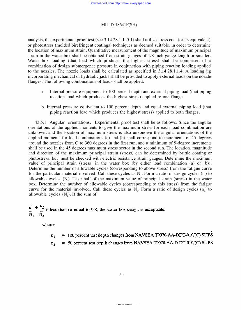
MIL-D-18641F(SH)
analysis, the experimental proof test (see 3.14.28.1.1 .5.1) shall utilize stress coat (or its equivalent)or photostress (molded birefringent coatings) techniques as deemed suitable, in order to determinethe location of maximum strain. Quantitative measurement of the magnitude of maximum principalstrain in the water box shall be obtained from strain gauges of 1/8 inch gauge length or smaller.Water box loading (that load which produces the highest stress) shall be comprised of acombination of design submergence pressure in conjunction with piping reaction loading appliedto the nozzles. The nozzle loads shall be calculated as specified in 3.14.28.1.1.4. A loading jigincorporating mechanical or hydraulic jacks shall be provided to apply external loads on the nozzleflanges. The following combinations of loads shall be applied.
a. Internal pressure equipment to 100 percent depth and external piping load (that pipingreaction load which produces the highest stress) applied to one flange
b. Internal pressure equivalent to 100 percent depth and equal external piping load (thatpiping reaction load which produces the highest stress) applied to both flanges.
43.5.1 Angular orientations. Experimental proof test shall be as follows. Since the angularorientations of the applied moments to give the maximum stress for each load combination areunknown, and the location of maximum stress is also unkonown the angular orientations of theapplied moments for load combinations (a) and (b) shall correspond to increments of 45 degreesaround the nozzles from O to 360 degrees in the first run, and a minimum of 9-degree incrementsshall be used in the 45 degrees maximum stress sector in the second run. The location, magnitudeand direction of the maximum principal strain (stress) can be determined by brittle coating orphotostress, but must be checked with electric resistance strain gauges. Determine the maximumvalue of principal strain (stress) in the water box (by either load combination (a) or (b)).Determine the number of allowable cycles (corresponding to above stress) from the fatigue curvefor the particular material involved. Call these cycles as N1. Form a ratio of design cycles (nl) toallowable cycles (Nl). Take half of the maximum value of principal strain (stress) in the waterbox. Determine the number of allowable cycles (corresponding to this stress) from the fatiguecurve for the material involved. Call these cycles as N2. Form a ratio of design cycles (n2) toallowable cycles (N2). If the sum of
50
Downloaded from http://www.everyspec.com
MIL-D-18641F(SH)
4.4 Shock resistance. Shock tests shall be conducted as specified in MIL-S-901 with thefollowing modifications:
a. Under the test procedure for medium weight equipment, the first blow in each groupshall be applied using the standard horizontal mounting adaptor; the second blow ineach group shall be applied with the unit mounted on adaptors holding it at a 30-degree angle from the horizontal in the direction of its least transverse strength.
b. Shock test extension will be considered for units if they are of a similar design,construction, weight, and materials to units which have successfully passed the test inaccordance with MIL-S-901. Shock test extension requests shall be prepared inaccordance with the instructions specified in MIL-S-901.
4.4.1 Shock resistance levels. As specified (see 6.2), shock resistance of distillation units shallbe in accordance with the following levels.
a. Level A - The distillation unit, after sustaining mechanical shock, shall operatenormally (see 3.12) and no parts thereof shall create a missile hazard to personnel orcontiguous apparatus or otherwise constitute a personnel hazard (such as a ruptureof parts containing steam or hot water, with consequent danger of scalding personnel)at the time of the shock.
b. Level B - The requirements of level B shall be the same as level A except that thedistillation unit need not operate normally after sustaining mechanical shock.
4.5 Vibration The distilling unit shall perform its function after the tests specified for typeI environmental vibrations of MIL-STD-167-1 (see 63).
4.6 Airborne and structureborne noise Airborne noise shall be measured in accordance withMIL-STD-740-1 for grade D equipment. Structureborne noise shall be measured at the mountingpoint in accordance with MIL-STD-740-2 (see 6.3).
4.6.1 Resilient mounts Equipment shall be mounted on resilient mounts even though theymay not be used in service.
4.6.2 Equipment shall be operating in the modes as specified (see 3.121 and 3.124).
4.7 Permanent tube plus Each permanent tube plug for saturated steam propelled surfaceship and submarine distilling plants shall be subjected to an internal hydrostatic test of not lessthan 1000 lbs/in2. Each plug shall be tight under this pressure and shall show no bulges, cracks,flaws, porous places, or other harmful defects. In addition, each permanent tube plug for submarinedistilling plants shall also be given a 100 percent liquid penetrant inspection in accordance withMIL-STD-271 on its outer surface after the hydrostatic test. The liquid penetrant inspectionstandards shall be as follows:
—
51
Downloaded from http://www.everyspec.com

MIL-D-18641F(SH)
a. Plugs which show the following liquid penetrant indications shall be subject to rejection:
(1)
(2)
(3)
Any liquid penetrant indications of cracks, seams, or laps, except scratches whosedepth is less than 5 percent of the wall thickness
Round indications 1/16 inch diameter or greater
Round indications which are linearly disposed whose center-to+enter distance isless than 3/16 inch.
b. Superficial polishing with 120 grit emery cloth may be used as an aid in determinationof the extent of the indications defined in a.(1), (2) and (3). Not more than 5 percentof the wall thickness shall be removed in the effort toprovided that design wall thickness is maintained.
c. If the vendor chooses to remove the defects, the areabe reinspected by liquid penetrant inspection afterindications have been removed.
remove the indications, always
containing the indication shallpolishing, to ensure that all
4.8 Inspection of packaging. Sample packages and packs, and the inspection of thepreservation, packing and marking for shipment and storage shall be in accordance with therequirements of section 5 and the documents specified therein.
5. PACKAGING
(The packaging requirements specified herein apply only forthe extent of applicability of the packaging, requirementssection 2, see 6.9.)
.
direct Government acquisition. Forof referenced documents listed in
5.1 Preservation. Preservation shall be level A or commercial as specified (see 6.2).
5.1.1 Level A. The distillation unit shall be preserved in accordance with method III of MIL-P-116. Interior surfaces shall be thoroughly dried after which openings shall be sealed with caps,plugs, or plywood blanks to prevent entry of foreign matter. Barrier material conforming to gradeA of MIL-B-121 shall be placed between the plywood blank and the mating flange.
5.1.1.1 Accessories. Gauges and thermometer shall be removed from the unit and individuallypreserved by methods IA and III respectively in accordance with MIL-P-116.
.
5.12 Commercial. The distillation unit shall be preserved in accordance with ASTM D 39-51.
5.2 Packing. Packing shall be level A, B, C, or commercial as specified (see 6.2).
52
Downloaded from http://www.everyspec.com

MIL-D-18641F(SH)
5.2.1 Levels A, B, and C with type, class, and style selection at the option of the contractor.The distillation unit shall be packed in a sheathed crate conforming to MIL-C-104. When specified(see 6.2), for levels B and C only, packing shall be in unsheathed crates conforming to MTLC-132 or MIL-C-3774. The closure and strapping of containers and the anchoring, blocking, bracing,cushioning and waterproofing of container contents shall be in accordance with the applicablecontainer specification or appendix thereto.
5.2.1.1 Detached accessories. Detached accessories, preserved as specified in 5.1.1.1 shall bepacked in boxes conforming to class 1 of PPP-B-621 or PPP-B-601 (domestic) and secured withinthe shipping containers with the complete unit.
5.2.2 Commercial. Distillation units, preserved as specified in 5.1, shall be individually packedin accordance with ASTM D 3951.
53 Marking. In addition to any special marking required (see 6.2), for levels A, B, and C,interior and exterior shipping containers shall be marked in accordance with MIL-STD-129,commercial containers in accordance with ASTM D 3951.
6. NOTES
(This section contains information of a general or explanatory nature that may be helpful, but isnot mandatory.)
6.1 Mended use. The distillation units specified herein are for making fresh water from sea-water in Naval shipboard installations with heated distillation units using low pressure steam orhot fresh water.
6.2 Acquisition requirements. Acquisition documents must specify the following:
ab.
c.
d.e.
f.
g.h.
Title, number and date of this specificationIssue of DODISS to be cited in the solicitation, and if required, the specific issue ofindividual documents referenced (see 2.1.1 and 2.2)Type of distillation unit to be supplied (see 1.2.1)
Class required (see 1.2.2)Level of resistance to mechanical shock (level A should be specified if operation of thedistillation unit is necessary to allow the ship to complete its immediate operation andto allow it to return to port) (see 3.2)
MTBF and MTTR (see 3.6)
Size and weight limitations, if applicable (see 3.10)
Limiting steam consumption for types 1, II, or III (low pressure steam for evaporatorsor salt water heater and high pressure steam for air ejectors) (see 3.121)
53
Downloaded from http://www.everyspec.com

MIL-D-18641F(SH)
i.
j.k.1.
m.n.
o.
p.q.r.
s.t.
u.
v.
w.
Amount and temperature of hot fresh water available for types IV or V (see 3.122and 3.12.3)
Temperature of distillate if higher than 95 ‘F is acceptable (see 3.12.5)
Rated capacity required (see 3.13 and 3.13.1)
Ship motion and attitude requirements, if other than specified (see 3.13.1)orientation of unit in the ship (see 3.13.1.1)
Whether circulating or feed pump must be mounted separately because of suctionwater level conditions (see 3.14 c)Discharge pumping heads required for pumps (see 3.14 d)
Whether feed pump is required (type I or III distilling units) (see 3.14 e)Whether brine overboard pump or brine eductor shall be furnished (see 3.14 f)
Whether air ejector and after condenser or vacuum pump is required (see 3.14.4 and3.14.26)Flange requirements, if different from those specified (see 3.14.7)Whether thicker tubes than number 18 BWG are required for submarine service(see 3.14.13)Steam pressure and temperature to air ejectors required (see 3.14.25) and to first effectsteam chest or salt water heaterVacuum pumps for types IV and V distilling units, when specified (see 3.14.26)
For submarine submergence pressure heat exchangers, requirements for attached sea-water piping (see 3.14.28.1.1.4)
x. Dimensions of hatch, bulkhead opening, or other access openings available for removalof corrugated basket of type III distilling units from the compartment in which the unitwill be installed (see 3.17.1.1)
y.. Whether gauges and thermometers, including replacements, shall be furnished with thedistilling unit (see 3.23.3 and 3.23.4)
z. Number of submarine distilling plant seawater feed heater permanent tube plugging testsets required (see 3.26.1 ) (It is intended that the tool set for submarines be carriedby the appropriate sub tenders and repair yards.) .
aa. For distilling plants exposed to submarine submergence pressure, MIL-Q-9858 shouldbe invoked for the quality assurance program. For all other distilling plants, either MIL-Q-9858 or MIL-I-45208 should be invoked for the quality assurance program (see 4.1and 4.1.1).
54
Downloaded from http://www.everyspec.com

MIL-D-18641F(SH)
bb. Hydrostatic pressure required (see 4.3.1)
u. If for submarine service, submergence test pressure (observe security requirements(see 4.3.1.1)
dd. Shock resistance level (see 4.4.1)ee. Selection of applicable levels of preservation and packing (see 5.1 and 5.2)ff. When packing shall be in unsheathed crates (see 5.21)
gg. Special marking required (see 5.3).
63 Consideration of data requirements. The following data requirements should be consideredwhen this specification is applied on a contract. The applicable Data Item Descriptions (DIDs)should be reviewed in conjunction with the specific acquisition to ensure that only essential dataare required/provided and that the DIDs are tailored to reflect the requirements of the specificacquisition. To ensure correct contractual application of the data requirements, a Contract DataRequirements List (DD Form 1423) must be prepared to obtain the data, except where DODFAR Supplement 27.475-1 exempts the requirement for a DD Form 1423.
Reference Paragraph
3.6
3.7
3.14 andappendix A
3.14.28.1.1,3.14.28.1.1.4.1,
and appendix C4.5
4.6
DID Number
DI-R-7085
DI-MNTY-80144
DI-DRPR-80651
DI-MISC-80652
UDI-T-23762
DI-HFAC-80272
DID Title Suggested Tailoring
Failure mode, effects,and criticality analysisreport
Maintainabilitydemonstration report
Engineering drawings
Technical informationreports
Report, vibration testing
Equipment airborne soundmeasurement test report
55
Level 3
Downloaded from http://www.everyspec.com

MIL-D-18641F(SH)
Reference Paragraph DID Number DID Title Suggested Tailoring
4.6 DI-HFAC-80274 Equipment structurebornevibratory accelerationmeasurement test report
4.4 DI-ENVR-80707 Shock test report
4.2 and 4.3.2 DI-MISC-80653 Test report
The above DIDs were those cleared as of the date of this specification. The current issue of DOD5010.12-L Acquisition Management Systems and Data Requirements Control List (AMSDL), mustbe researched to ensure that only current, cleared DIDs are cited on the DD Form 1423.
63.1 Special guidance when ordering equipment for the Naval Sea Systems Command(NAVSEA). The table below lists, as a separate line item, every candidate data deliverable arisingfrom this specification and lists the reference paragraph for the deliverable. When this specificationis invoked in a contract to purchase equipment for NAVSEA, items marked with a "Yes” shouldbe prepared and delivered:
Reference Paragraph
3.14 and appendix A
3.14.28.1.1 andappendix C
4.2
4.3.2
4.4
4.5
4.6
6.4 and appendix B
Name of Deliverable
Drawings
Design report
Report of qualification tests
Report of performance testsafter installation
Shock test report
Report of environmentalvibration text
Report of airborne andstructureborne noise tests
Technical manual
56
Desired on ordersfor equipment forNAVSEA
Yes
Yes
Yes
Yes
Yes
Yes
Yes
Yes
Downloaded from http://www.everyspec.com

MIL-D-18641F(SH)
6.4 Technical Manuals. The requirement for technical manuals should be considered whenthis specification is applied on a contract. If technical manuals are required, military specificationsand standards that have been cleared and listed in DOD 5010.12-L Acquisition ManagementSystems and Data Requirements Control List (AMSDL) must be listed on a separate ContractData Requirements List (DD Form 1423), which is included as an exhibit to the contract- Thetechnical manuals must be squired under separate contract line item in the contract. Technicalcontent should include the requirements of appendix B, titled ‘Technical Manual Technical ContentRequirements. w
6.5 Qualification. With respect to products requiring qualification, awards will be made onlyfor products which are, at the time of award of contract, qualified for inclusion in QualifiedProducts List No. 18641 whether or not such products have actually been so listed by that date.The attention of the contractors is called to these requirements, and manufacturers are urged toarrange to have the products that they propose to offer to the Federal Government tested forqualification in order that they may k eligible to be awarded contracts or purchase orders forthe products covered by this specification. The activity responsible for the Qualified Products Listis the Naval Sea Systems Command, SEA 05Q22, 2531 Jefferson Davis Hwy, Arlington, VA 22242-5160 and information pertaining to qualification of products may be obtained from that activity.Application for qualification tests must be made in accordance with “Provisions GoverningQualification SD-6” (see 6.5.1).
6.5.1 Copies of “Provisions Governing Qualification SD-6" may be obtained upon applicationto Standardization Documents Order Desk 700 Robbins Ave., Building 4D, Philadeiphia, PA19111-5094.
6.6 For saturated steam propelled ship distilling plants, distilling plant manufacturer shouldforward the following to NAVSEA:
a. Permanent tube plugging procedure
b. Drawings of the permanent tube plug and tools (including tapered tube plug)
c. Drawings showing the permanent plug and each tool inend or permanent plug.
6.6.1 The drawings and procedures specified in 6.6 should betechnical manual.
its proper position in the tube
included in the distilling plant
6.7 Provisioning. Provisioning Technical Documentation (PTD), spare parts, and repair parts.should be furnished as specified in the contract.
6.7.1 When ordering spare parts or repair parts for the equipment covered by this specification,the contract should state that such spare parts and repair parts should meet the same requirementsand quality assurance provisions as the parts used in the manufacture of the equipment. Packagingfor such parts should also be specified.
57
Downloaded from http://www.everyspec.com

MIL-D-18641F(SH)
6.8 Sub-contracted material and parts. The packaging requirements of referenced documentslisted in section 2 do not apply when material and parts are acquired by the contractor forincorporation into the equipment and lose their separate identity when the equipment is shipped.
6.9 Subject term (key word) listing.
BafflesBrineFlangeFlash chamberShellWaterbox
6.10 Changes from previous issue. Marginal notations are not used in this revision to identifychanges with respect to the previous issue due to the extensiveness of the changes.
Preparing activityNavy - SH
(Project 4620-N034)
58
Downloaded from http://www.everyspec.com

MIL-D-18641F(SH)APPENDIX A
ENGINEERING DRAWINGS TECHNICAL CONTENT REQUIREMENTS
10. SCOPE
10.1 Scope. This appendix covers the technical content that shall be included on drawingswhen required by the contract or order. This appendix is mandatory only when data itemdescription DI-DRPR-80651 is cited on the DD Form 1423.
20. APPLICABLE DOCUMENTS
This section is not applicable to this appendix.
30. DRAWING CONTENTS
30.1 Drawing types. The following types of drawings are required:
a. Outline drawings. Outline drawings are external arrangement drawings that shall showall necessary external views of the unit and shall include all external dimensionsrequired for reproduction on ship’s machinery arrangement drawings, for guidance ofthe shipyard in designing the foundation structure for the unit, for installation thereof,and for connection of the unit to the external piping. The drawing shall show thespace required for removal and replacement of tubes in the heat exchanger components,removal of water boxes, covers of access openings, zinc anodes, vapor separators,location of lifting lugs or eyebolts provided for handling of the unit or its componentsand size of openings therein provided for lifting.
b. Assembly drawings. Assembly drawings shall show complete longitudinal and transversecross sectional views of the unit, relationship of all parts, arrangement of tubes in heatexchanger components, method of tube end expansion, baffles, vapor separators, andwelding of adjacent parts. Liberal use of enlarged views or sections shall be made. Ifnecessary, subassembly drawings conforming to the above may be furnished forindividual components of the unit. The drawing shall be such that a thoroughunderstanding of the design and construction of the apparatus may be obtained withoutreference to the related detailed drawings.
c. List of materials. The assembly drawing shall contain a list of materials showing namesof parts with identifying numbers and materials of all parts. The identifying numbersshall also be shown adjacent to the part depicted in the various views, with arrowspointing to the parts.
59
Downloaded from http://www.everyspec.com

MIL-D-l8641F(SH)APPENDIX A
d.
. e.
f.
g.
Zinc anodes. The drawing shall indicate that the zinc anodes providedexchanger comply with the requirements of MIL-A-19521, as modified3.14.24).
Major parts. _ Detail drawings_of all major parts such as shells, water boxes,
in the heatherein (see
tube sheets,tube supports, baffles, vapor separators, demister, flash cones and air ejectors shall beprovided. The drawings shall be completety dimensioned with finishes and weldingsymbols indicated, as required for manufacture.l
Diagrammatic piping arrangement A diagrammatic piping arrangement drawing shallbe provided showing complete piping required for the operation of the apparatus, withpiping furnished with the apparatus and that to be furnished by the shipbuilder clearlyindicated. Location of gauges, thermometers, valves, orifice plates, acid cleaningconnections, and salinity indicators shall be indicated.
Electrical components. A wiring and connection drawing or drawings shall be providedfor such electrical components as are furnished as part of the unit.
30.2 Tabulation. Tabulated drawings are encouraged as a means to reduce drafting time,number and size of detail drawings.
30.3 Certification data sheets. Certification data sheets shall be provided and shalla tabulation of the following data:
a. Velocity of circulating water under rated conditions in the tube of each com
include
onent
b. Complete heat balance diagrams for showing capability of the unit to produce ratedcapacity over the required operating range. Diagrams for seawater temperatures of 28,60, and 85 “F are required. In addition for submarine service a diagram for 45 “F isrequired.
c. Hydrostatic test pressure for all components, list of on board repair parts furnished andall similar pertinent design data
d. A drawing list tabulation with columns for drawing title, manufacturer’s drawing numberand revision symbol. This list shall include all equipment drawings which comprise thedesign. The revision symbol column shall be kept up to date to the time of manufactureso that it will finally indicate for each drawing the revision applicable to the equipmentas buiit-
60
Downloaded from http://www.everyspec.com

MIL-D-18641F(SH)APPENDIX A
30.4 Sufficient drawings shall be provided to:
a.
b.
c.
d.
e.
Provide design information sufficient to ensure conformance to the requirements of thisspecification including compatibility with ship and ship systems
Evaluate the suitability of design for intended Naval use
Evaluate performance and maintenance capability
Enable shipyard installation without contractor’s assistance
Enable Naval ship and shore activities to repair and maintain the item withoutassistance from the original contractor.
30.5 Bolting torque. The bolting preload torque shall be specified in the applicable componentdrawings.
30.6 Critical materials. Critical materials shall be designated on drawings.
61
Downloaded from http://www.everyspec.com

MIL-D-18641F(SH)APPENDIX B
TECHNICAL MANUALS TECHNICAL CONTENT REQUIREMENTS
10. SCOPE
10.1 Scope This appendix covers the technical content that shall be included in technicalmanuals when required by the contract or order. This appendix is mandatory only when deliveryof a technical manual is required by contract.
20. APPLICABLE DOCUMENTS
This section is not applicable to this appendix.
30. TECHNICAL MANUAL CONTENTS
30.1 Content requirements. Technical manuals shall be in accordance with MIL-M-15071. Technical manuals shall include sufficient drawings to permit ship and shore activities torepair and maintain the unit without contractor’s assistance. The manual shall contain instructionsfor proper installation of locking devices and criteria for their renewal. The manual shall includetorque values for seawater containing element fasteners. The technical manual shall specify theexperimentally determined values of bolting preload torque. The technical manual shall includecomplete operating instructions including initial inspections, step-by-step startup procedure,operation checks and adjustments, operation maintenance and step-by-step shutdown procedure.
62
Downloaded from http://www.everyspec.com

MIL-D-18641F(SH)APPENDIX C
TECHNICAL REPORT TECHNICAL CONTENT
10. SCOPE
REQUIREMENTS
10.1 Scope. This appendix covers the technical content requirements that shall be includedin technical reports when required by the contract or order. This appendix is mandatory only whendata item description DI-MISC-80652 is cited on the DD Form 1423..
20. APPLICABLE DOCUMENTS
This section is not applicable to this appendix.
30. DESIGN REPORT
30.1 Design report content. When required by the contract or order, design report contentfor applications for which cyclic life requirements are established, shall contain an analysisdemonstrating the adequacy of the design. For heat exchangers designed for submergence pressure,a design report shall be included. The report shall be in a format to facilitate an independentreview of its content. lt is, therefore, imperative that it be simple to follow, free from ambiguity,and should
a.
b.c.d.
e.
f.
g.h.
i.
j.
contain the following as a minimum:
Description of design requirementstemperatures, and external loading
Regions of the component analyzed
such as steady state transient pressures,
Materials used and their mechanical properties
General description of the methods of analysis and assumptions
All reference sources shall be listed.
All computer programs shall be properly identified and described.
Report contains copies of the computer printouts (input and output).Stresses shall be tabulated for each area of investigation and compared to the allowablestresses for all stress categories.
Satisfaction of cyclic requirements including stress concentration factors used in thecyclic analysis.
Manufacturer shall submit calculations demonstrating that the free length of tubesprovided between the double tube sheets is sufficient to comply with 3.14.28.1.1.
63
Downloaded from http://www.everyspec.com

Downloaded from http://www.everyspec.com


![IINCH-POUND ] MIL-S-24235/16B (SH) 28 December 1992 …everyspec.com/MIL-SPECS/MIL-SPECS-MIL-S/download.php?... · iinch-pound ] mil-s-24235/16b (sh) 28 december 1992 superseding](https://static.fdocuments.net/doc/165x107/614879662918e2056c22b67c/iinch-pound-mil-s-2423516b-sh-28-december-1992-iinch-pound-mil-s-2423516b.jpg)