MIL-B-62346A(AT) SUPERSEDING MIL-B-62346(AT) MILITARY...
27
MIL-B-62346A(AT) 10 January 1983 SUPERSEDING MIL-B-62346(AT) 1 March 1982 MILITARY SPECIFICATION BATTERIES, STORAGE: LEAD-ACID (LOw-MAINTENANCE) This specification is approved for use by the US Army Tank- Automotive Command and is available for use by all Departments and Agencies of the Department of Defense. 1. SCOPE .1.1 .Scope. This “specification covers one type of waterproof, low maintenance, lead-acid batteries, furnished in charged and dry or charged and wet condition, for starting, “lighting, and ignition service in military vehicles. Battery designation shall be as follows: Type Ratsd reserve Ampere-Ho-urs “designation Voltage ~ity minutes (20 Hour Rate). -, ● 6TL 12 200 120 2* Government documents. 2.1.1 Specifications, standards, and handbooks. Unless other- wise specified, the following specifications, standards, and handbooks of the issue listed in that issue of the Department of Defense Index of Specifications and Standards (DoDISS) specified in the solicita- tion form a part of.this specification to the extent specified herein. Beneficial comments (recommendations , additions, deletions) and any pertinent data which may be of use in improving this document should be addressed to: US Army Tank-Automotive Command, ATTN: DRSTA-GSS, Warren, MI 48090, by using the self-acldressed Standardization Document Improvement Proposal (DD Form 1426) appearing at the end of this document, or by letter. FSC 6140 Downloaded from http://www.everyspec.com
Transcript of MIL-B-62346A(AT) SUPERSEDING MIL-B-62346(AT) MILITARY...

MIL-B-62346A(AT)10 January 1983SUPERSEDINGMIL-B-62346(AT)1 March 1982
MILITARY SPECIFICATION
BATTERIES, STORAGE: LEAD-ACID(LOw-MAINTENANCE)
This specification is approved for use by the US Army Tank-Automotive Command and is available for use by all Departmentsand Agencies of the Department of Defense.
1. SCOPE
.1.1 .Scope. This “specification covers one type of waterproof,low maintenance, lead-acid batteries, furnished in charged and dryor charged and wet condition, for starting, “lighting, and ignitionservice in military vehicles. Battery designation shall be asfollows:
Type Ratsd reserve Ampere-Ho-urs“designation Voltage ~ity minutes (20 Hour Rate).-,
● 6TL 12 200 120
2* Government documents.
2.1.1 Specifications, standards, and handbooks. Unless other-wise specified, the following specifications, standards, and handbooksof the issue listed in that issue of the Department of Defense Indexof Specifications and Standards (DoDISS) specified in the solicita-tion form a part of.this specification to the extent specifiedherein.
Beneficial comments (recommendations , additions, deletions) and anypertinent data which may be of use in improving this document shouldbe addressed to: US Army Tank-Automotive Command, ATTN: DRSTA-GSS,Warren, MI 48090, by using the self-acldressed StandardizationDocument Improvement Proposal (DD Form 1426) appearing at the end ofthis document, or by letter.
FSC 6140
Downloaded from http://www.everyspec.com
NIL-B-62346A(AT)
SPECIFICATIONS
FEDERAL
0-S-801
STANDARDS
FEDERAL
FED-STD-595FED-’STD-6O1
MILITARY
MIL-STD-105 Sampling Procedures and Tables forInspection by Attributes.
MIL-STD-129 - Marking for Shipment and Storage.MIL-STD-202 Test Methods for Electronic and
Electrical Component Parts.MIL-sTP-45662 - Calibration System Requirements .,MS52149 - Battery, Storage, Lead-Acid (Low-.
Maintenance) .
2.1.2 Other Government documents, drawings, and publications.The following other Government documents,
●drawings, and publicationsform a part of this specification to the extent specified herein.
DEPARTMENT OF TRANSPORTATION (DOT)Federal Motor Carrier Safety Regulations - 49 CFR ‘
(Application for copies should be addressed to the Department ofTransportation, Washington DC 20590) .
- Sulfuric Acid, Electrolyte; for StorageBatteries.
- Colors- Rubber, Sampling and Testing
Downloaded from http://www.everyspec.com

MIL-B-62346A(AT)
● (Copies of specifications, standards, handbooks, drawings, andpublications required by manufacturers in connection with specificacquisition functions should be obtained from the contractingactivity or as directed by the contracting officer) .
2.2 Other publications. The following documents form a partof this specification to the extent specified herein. The issuesof the documents whic”h are indicated as DoD adopted shall be theissue listed in the current DoDISS and the supplement thereto, ifapplicable.
UNIFORM CLASSIFICATION COMMITTEE
Consolidated Freight Classification Rating, Rules, andRegulations.
(.Application for copies should be addressed to the UniformClassification Committee, 222 South Riverside Plaza, Chicago, IL60606).
SOCIETY OF AIJTOMOTIVE ENGINEERS, INC. (SAE)SAE J537i - Storage Batteries.
(Application for copies ,should be addressed to’ the Society ofAutomotive Engineers, Inc. , 400 Commonwealth Drive, Warrendale, PA15096).
BAIrTERY couNcIL INTERNATIONAL (BcI)
Bulge .Characteristics of Storage Battery2 Manufacturing Industry Testing Procedures.
(Application for copies should be addressed to6~:;:~ry CouncilInternational, 111 East Wacker Drive, Chicago, IL .
(Industry association specifications and standards are generallyavailable for reference from libraries. They are also distributedamong technical groups and using Federal agencies).
Downloaded from http://www.everyspec.com
MIL-B-62346A(AT)
3. REQUIREMENTS
3.1 Qualification. The battery furnished under this speci-●
fication shall be’s product which is qualified for listing on theapplicable Qualified Product List (QPL) at the time set for openingof bids (see 4.6, and 6.3).
3.2 Materials. Materials shall be as specified herein and inreferenced specifications, standards and drawings. Material shallbe free of defects which adversely affect performance or service-ability of the finished product (see 6.4).
I3.2.1” Electrolyte. The electrolyte, use in filling batteries
procured in the charged and wet condition for test purposes, shallconform to Class 3 of 0-S-801.
I3.2.2 Active material. Active material reclaimed from plates
of other batteries shall not be used.
3.3 Construction. Batteries shall be constructed in accordancewith MS52149.
3.3.1 Containers,. Containers shall be molded to the dimensionsspecified in MS52149. The containers shall be free of leaks,blisters, cracks, or other defects that could adversely affect theperformance of the battery. Container color shall be lusterlessolive drab, conforming to color chip number 34087 of FED-STD-595.The container shall be made from nonabsorbent, acid-resistant, athermoplastic material meeting the physical requirements specified in
3.4.1 through 3.4.4. . ..
I3.3.2 Battery cover. Battery cover shall meet the same
physical and color requirements as the container material. Batterycover shall be of one-piece design and shall be sealed to thecontainer, thereby forming a case. Cover and base are to beparallel within 0.060, total. The seal shall mtiintain an acid tightjoint between case and cover under all test’ conditions specifiedherein.
3.4= Physical requirements.
tandrms)
3.4.1 Electrical breakdown.an alternating current potenper mil of thickness without
Thetialdam
batof
age.
tery100
convolt
tainer shall with-s root mean square
4 ,
●
Downloaded from http://www.everyspec.com
WIL-B-62346A(AT)
3.4.2 Acid absorption.
●The battery,container material shall
exhibit no cracks or blisters~ no more than 1.5 percent increase inweight, and no more than 2 percent increase in any physical dimensionin a 1.300 specific gravity electrolyte solution at 150° ~ 2°F(65.6° ~ I“C) for a period of 7 days.
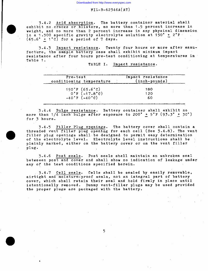
3.4.3 Impact. resistance. Twenty four hours or more after manu-facture, the sample battery case shall exhibit minimum impactresistance after four hours pre-test conditioning at temperatures inTable 1.
TABLE I. Impact resistance.
Pre-test Impact resistanceconditioning temperature (inch-p ounds)
150”F (65.6”C) 180O“F (-17.8”C)
-40”F (-40°c)12060
3.4.4 Bulge resistance. Battery container shall exhibit nomore than 1/4 inch’ bulge after exposure to 200” s 5°F (93.3° : 3C”)for 3 hours.
3.4.5 l?iller Plug opqnings. The battery cover shall contain a
●threaded vent filler plug opening for each cell (See 3.4.8). The ventfiller plug openings shallbe designed to permit easy determinationof the electrolyte level. Electrolyte level instructions shall beplainly marked, either on the battery cover or on the vent fillerplug.
3.4.6 Post seals. Post seals shall maintain an unbroken sealbetweeen post and cover and shall show no indication of leakage underany of the test conditions specified herein.
.3.4.7 Cell seals. Cells shall be sealed by easily removable,airtight and moisture-proof seals, not an integral part of batterycover, which shall retain their seal and hold firmly in place unti3intentionally removed. Dummy vent-filler plugs may be used providedthe proper plugs are packaged with the battery.
5
●
0
Downloaded from http://www.everyspec.com
I MIL-B-62346A(AT)
3.4.8 Vent filler plugs. Nonabsorbent, acid resistant fillerplugs shall be provided for each cell. The plugs shall have nominal7/8-9-UNC-2A threads for mating with the threaded 1/8 inch raised
aopenings in the cell cover. The vent filler plugs shall be of thesubmersible type, shall incorporate a vent with a check valve topermit the escape of gases from the battery, and shall be dualcolored (red top and natural body without pigment). The check valvesshall not leak more than two drops of water in 10 seconds when undera four foot head of water, and shall be designed to open beforeinternal pressure reaches 0.5 pounds per square inch (psi) in excessof the external pressure. The plugs shall withstand temperaturesfrom minus 65”’F (-53.9°C) to plus 250”F (121”C) without cracking,melting, or other damage.
3.4.9 Handles. Handles shall be rope type plastic of thedeveloped length specified in MS52149. Handles shall withstand theeffects of electrolyte conforming to Class 3 of 0-S-801 (see 3.2.1).Each handle shall be attached to the battery case in such manner asto withstand, without damage to the case, the handle, or the attach-ment, a force of 1.4 times the filled weight of the battery whentested in accordance with 4.8.8 at temperatures of 190”F ~ 2°F (88°+ l“C) and minus 65° ~ 2°F (-54” ~ 10).—
3.4.10 Grids and plates. Grids shall have no framing barscracked, broken ,or missing. After pasting of active material, platesshall evidence no holes in the active material.
3.4.10.1 Plates. Plates shall be”of the pasted type and the ~grid lead alloy shall conkain no antimony. Optional ”construction : ●Negative plate grids shall have non-antimony or low percent (not to’exceed 1.0 percent) antimony and positive plate grids (not to exceed3.5 ,percent) antimony.
, 3.4.11 Plate connections and intercell connectors. plates ofiike polarity in eachcell shall be integrally joined by intercellconnectors. The intercell connectors shall be of the burned-on,,.cast-on, or welded type. ,Each connector shall be of such size” andstrength as to provide. both electrical conduction and support foreach group of like polarity plates. Plate-connecting intercellconnectors of the up and over type shall not be used. ,,,
3.4.12 Separators. Separators shall be an envelope type, “enclosing the positive plates and shall extend a minimum of 3/32 inchabove plates after assembly.
.
Downloaded from http://www.everyspec.com

I
MIL-B-62346A(AT)
,. 3.4.13 Terminal posts. Terminal posts shall be of the designand-location specified on. the applicable standard.’
e
The positivetapered terminal post shall be identified by a “+” a “POS”, or a “P”and the negative tapered terminal by a “-” a ‘fNEG”, or “N” as shown onthe standard. All metal parts of terminal shall be lead or lead-coated’. Taper to be 1.33 inches per foot.
3.4.13.1 Terminal post torque resistance. Tapered terminalposts shall be withstand, without damage to the battery, a torque of250 inch-pounds.
3.5 Battery condition. Batteries shall be furnished in oneof the following conditions as specified (see 6.2):.-
1 Charged and dry - 65 pounds approximateCharged and wet - 84 pounds approximate
3.5.’1 Charged and dry. Batteries furnished in the charged anddry condition shall contain dry plates and separators. The moisturecontent of the separators shall not exceed 3.0 percent. .The moisturecontent of the plates shall not exceed 0.2 percent. NO electrolyteshall be furnished.
3.5.1.1 Dry cell internal resistance. The terminal-to-terminalresistance of each cell, measured after~sembly in the containerwith the ,top off, shall be no less than 50,000 ohms. If each cellof the battery has a minumum resistance of 5,000,000 ohms after
o assembly in the container, the moisture test in paragraph 4.8.10 maybe omitted.
3.,5.2 .Charged and wet. Batteries furnished in the. charged andwet condition .,shall be charged and dry ‘batteries filled to the properlevel with ,electrolyte as specified in 3.2.I and shall be fullycharged when shipped. When fully charged, the specific gravity of theelectrolyte shall be 1 .280 + .010, corrected to electrolyte tempera-ture of ‘80°F (’27°C) and the–open circuit, terminal-to-terminal voltageshall be not less than two volts per cell corrected to 80”F (27°C).
,“
‘,.
.,
. . 7
● ✌✌
Downloaded from http://www.everyspec.com
MIr,-B-62346A(AT)
3.6 Battery performance. ,.
3.6.1 Cold activation of dry Batteries furnished incharged. ●the charged and dry condition shall exhibit a terminal voltage’of 7.2volts or greater following a discharge rate of 450 amps for 60seconds, after stabilizing the dry charged battery at 30”F + 2°F(-l”c: I“C), and filling the battery with electrolyte also—stabilizedat the 30”F temperature.
3.6.2 Full charge capacity (80”F). Each battery shall yield acapacity of not less than 120 ampere hours at a controlled temperatureof 80° ~ 5°F (27°C ~ 3“C).
3.6.3 Reserve capacit~. Fully charged batteries stabilized at80 + 5°F (27 + 3“C) shall exhibit a minimum terminal voltage “of10.3 after a ~ischarge rate of 25 amp for 200 minutes.
3.6.4 Low temperature capacity. Fully charged batteries (1.280specific gravity, minimum) shall exhibit a minimum terminal voltage of7.2 volts after being discharged for 30 seconds at the rates and ““temperatures shown below:
Temperature Discharge rate
O“F 600 amps,.
-40”F 350 amps
3.6.5 Retention of charge. ‘Following 30 days storage at 105°F”(40.6°C), batteries shall successfully survive a discharge rate of 25
9
amps for 175 minutes to a minimum terminal voltage of 10~5 volts. ,,
3.6.6 Electrolyte retention. Batteries shall evidence noleakage or spillage when tilted through a angle of 45 degrees .frorn ~the normal plane of either major or minor axis.
3.6.6.1 Leakage. Each cell shall independently maintain apressure of 0.5 psi for a period of 30 seconds with a maximumpressure loss of 0.1 psi.
3.6.7 Extreme temperature resistance. Batteries shall show nocracking of containers, covers, sealers filler plugs, or ’other damagedue to temperature change between plus 190°F (88”C) and minus 65°F(minus 54°C) and no more than 0.1 psi pressure drop in 30 seconds,with 0.5 psi pressure applied to each cell individually after exposureto extreme test temperatures.
Downloaded from http://www.everyspec.com

MIL-B-62346A(AT)
—
3.6.8 Vibration resistance. Batteries shall maintain a
steady voltage and current with no loosening of terminal posts inthe cover; flooding of electrolyte at the top; intercell leakage;excessive sediment; broken connections, straps or plates; brokenor defective separators; or other damage while being subjected tovibration through an amplitude of 0.04!5 to 0.050 inches (0.090to 0.100 inch total excursion) at a frequency of 2000 to 2100cycles per minute. Vibration shall not decrease the reservecapacity of batteries below 190 minutes.
3.6.9 Life-cycle capacity. Battery shall withstand 235discharge/charge cycles. The life cycles attained by eachbattery shall be taken as the total actual cycles completed onlife cycle tests, plus each cycle attained on other tests.
3.6.10 Storage life. After 90 days of storage at standardtest conditions the battery shall meet the requirements of 3.6.1.
3.7 Identification marking. Marking data shall be appliedto a permanent, electrolyte-resistant type label or nameplate, ormay be molded on battery container. Labels and nameplates shall besecurely and permanently attached to the side of the battery.
3.7.1 Identification data. Identification marking shall showthe following:
a.
b.c.d.e.f.
g“h.i.j=
Battery identification (battery, storage, lead-acid, lowmaintenance).
Designation (Military and ,SAE, when applicable).MS part number.Voltage.Reserve capacity at 80”F (26.7’’C).High discharge capacity and rate at O°F (-17.8°C) and-40”F (-40”C).
Contract or order number.Date of manufacture (month and year) and lot numberManufacturer’s name.us
3.7.2 Instruction tag and label. Instruction tag and label/which provide complete information for placing battery in service,operation, and charging shall be attached in a conspicuous place oneach battery.
3=7.3 Instruction (charged and dl~. Instructions for chargedand dry batteries shall contain the folllowi.ng information:
9
.
Downloaded from http://www.everyspec.com
MIL-B-62346A(AT)
a. NOTE: This is a charged and dry storage battery. Whenplacing in service, mark top of battery with the dateactivated. ●
b. Remove and destroy sealing devices which seals cellsduring shipment and storage.
CAUTION: Do not remove sealing devices until ready to fillbattery.
d.
e.
f.
g“
h.
i.
j.k.
Fill each cell with electrolyte (sulfuric acid and watersolution) of 1.280 + .005 specific gravity at 80”F(26.7”C) to designa~ed level. Temperature of thebattery and the electrolyte must be above 60”F(15.6”C), but preferably not above 100”F (37.8”C).
Allow the battery to stand for 30 minutes after fillingthen check electrolyte specific gravity of each cellcorrecting the reading to 80”F (26.7”C). Add electro-lyte if necessary to bring to designated level.
The battery shall be charged fully before it is put intoservice.
The battery should be charged at a constant potential of15.0 volts until specific gravity becomes constant forthree consecutive 30-ninute readings. The temperature ofthe electrolyte during the charging period shall not beallowed to exceed 120”F (48.9”C)..Add electrolyte as required to bring to proper level.Add only distilled water or drinking water, afterinitial charge, to maintain proper level.
Keep the top and sides of the battery clean.and dry.Make sure vent-filler plugs are clean. When clean-ing is required~ wash with water.
Battery should be charged every 6 months and kept incool, dry storage, when not in use.
Electrolyte volume .—.Charging voltage:
—————15 volts, constant potential.
a
Downloaded from http://www.everyspec.com

MIL-B-62346A(AT)
●3.7.4 Instructions (charged and wet). Instructions for charged
and wet batteries shall contain the fol=wing information:
NOTE: This is a CHARGED and WET storage battery. It wasactivitated at time of manufacture and charged tofull rated capacity.
a.
b.
c*
d.e.
f.
~=
on the battery cover, indicate the date (month, andyear) of preparation for service.
Check, the electrolyte specific gravity and levels inall cells, and adjust to the proper levels by addingdistilled or drinking water as required. Charge at :a constant voltage of 15 until the specific gravityof the electrolyte remains constant for threeconsecutive reading taken at 30-minute intervals.
Check the electrolyte levels. Add distilled or ~drinking water, as required, to maintain proper level.Add the water only while the battery is being charged.
The battery is now ready for use.Keep the top and sides of the battery clean and dry.Make sure the vent-filler plugs are clean. Whencleaning is required, wash with water.
Battery should be charged every 6 months and kept incool, dry storage when not in use.
Charging voltage: 15 volts, constant potential.
e 3.8 Workmanship. Batteries shall be processed in such a manneras to be uniform in quality and free c)f defects that will affecttheir life, serviceability, or appearance. Containers, covers, andvent filler plugs shall be free of crscks, leaks, and “broken parts.Lead-burning shall be homogeneous and free of blow-holes or imperfectbonds between parts which have been burned together. Marking shallbe clear and distinct.
11
Downloaded from http://www.everyspec.com
MI L-B-62346 A(AT)
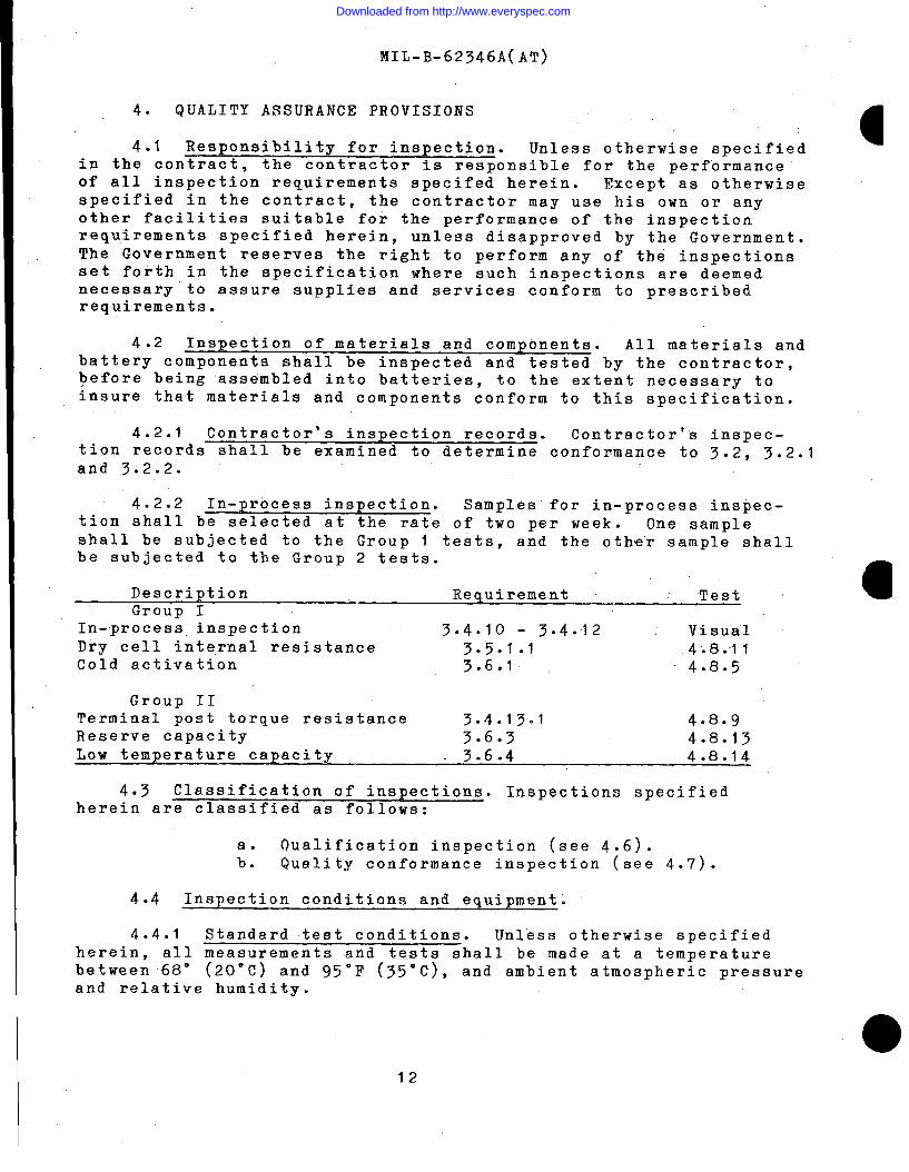
4. QUALITY ASSURANCE PROVISIONS
4*1 Responsibility for inspection. Unless otherwise specifieda
in the contract, the contractor is responsible for the performance’of all inspection requirements specifed herein. Except-as otherwisespecified in the contract, the contractor may use his own or anyother facilities suitable for the performance of the inspectionrequirements specified herein, unless disapproved by the Government.The Government reserves the right to perform any of the inspectionsset foith in the specification where such inspections are deemednecessary’to assure supplies and services conform to prescribedrequirements.
I 4.2 Inspection of materials and components. All materials andbattery components shall be inspected and tested by the contractor,before being ‘assembled into batteries, to the extent necessary toinsure that materials and components conform to this specification.
I4.2.1 Contractor’s inspection records. Contractor’s inspec-
tion records shall be examined to determine conformance to 3.Z, 3.2.Iand 3;2.2.
4.2.2 In-p recess inspection. Samples for in-process inspec-tion shall be selected at the rate of two per week. One sampleshall be subjected to the Group 1 tests, and the other sample shallbe subjected to the Group 2 tests.
Description Requirement Test aGroup I
IIn-process inspection 3.4.10 - 3.4.12 : Visu”a’1Dry cell internal resistance 3.5.1.1 4;8.11Cold activation 3.6.fl 4.8.5
Group 11Terminal post torque resistance 3.4.13.1 4.8.9Reserve capacity 3.6.3 4.8.13Low temperature capacity 3.6.4 4.8.14
4.3 Classification of inspections. Inspections specifiedherein are classified as follows:
a. Qualification inspection (see 4.6).b. Quality conformance inspection (see 4.7).
4.4 Inspection conditions and equipment.
4.4.1 Standard test conditions. Unless otherwise specifiedherein, all measurements and tests shall be made at a temperaturebetween 68° (20”C) and 95°F (35”C), and ambient atmospheric pressureand relative humidity.
12
Downloaded from http://www.everyspec.com

MIL-B-62346A(AT)
4.4.2herein, thetest’s sha.’ll
Temperature of electrolyte. Unless otherwise specifiedtemperature of the electrolyte at the beginning of thebe within ~ 2°1’ of the test temperature.
4.4.3 Test equipment. Test equipment shall be of sufficientaccuracy and quality to permit performance of the required tests.The contractor shall establish adequate calibration of test equip-ment to the satisfaction of the Government. Precision measuringinstruments shall conform to the requirements of MIL-STD-45662.
4.4.3.1 Hydrometer. The hydrometer shall provide a floataccuracy of plus or minus 3 points (.003) throughout the’ specificgravity scale and temperature range.
4.4.4 Instrument accuracy. .
4.4.4.1 Electrical indicating instruments. All voltmeters andammeters used in testing batteries shall be accurate within ~ 0.5percent of full scale value. The sensitivity of voltmeters shall beat least 20,000 ohms per volt. The voltmeter and ammeter ranges usedshall be such that all readings are taken on the upper half of thescale.
4.4.4.2 Resistor tolerances. In all tests involving dischargethrough a resistance, such resistance shall be accurate within+ 0.5 percent.—
4.5 Discharging and tiharging of test batteries.
4.5.1 Discharging. The fully charged battery shall be at atemperature of 80° I 5°F (26.7 ~ 3“C) and shall be discharged at the20 hour rate (that current in amperes equal to l/20th of thebattery’s rated ampere hour capacity), to a final average terminalvoltage equivalent to 1.75 volts per cell, unless otherwise speci-fied .
4.5.2 Charging. Batteries shall. be charged at a constantvoltage of 15.0 volts until specific gravity’ reading taken at 30minute intervals remains constant. The temperature of the electro-lyte during the charging period shall not be allowed to exceed 120°F(48.9”C). Optional: Batteries shall be charged as specified in SAEStandard J537.
4.5.3 Periodic charging. If the testing on any activatedbattery is temporarily stopped for a period of 48 hours,, the batteryshall be given a freshening charge at the specified rate until fullycharged (see 4.5.2) before testing is resumed. A battery shall neverbe stored for more than 24 hours after a discharge, without beingrecharged . \
13
Downloaded from http://www.everyspec.com
MIL-B-62346A(AT)
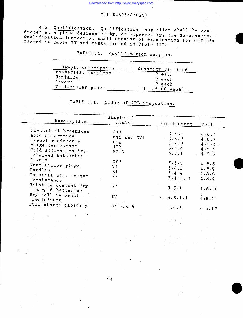
4.6 Qualification. Qualification inspection shall be con-ducted at a place designated by, or approved by, the GovernmentQualification inspection shall consist of examination for defects.listed in Table IV and tests listed in Table III.
TABLE II. Qualification samples.
Sample description QuantityBatteries, complete
required
Container8 each2 each
Covers 2 eachVent-filler plugs 1 set (6 each)
.
TABLE III. Order of QPL inspection.
——Samnle 1/ .—
,’
Descriptionr_- -!number Requirement Test —
Electrical breakdownAcid absorptionImpact resistanceBulge resistanceCold activation drycharged batteries
CoversVent filler plugsHandlesTerminal post torqueresistance
Moisture content drycharged batteries
Dry cell, internalresistance
Full charge capacity’
,,
CT1CT2 and CV1C!(’2CT2B2-6
CV2VIB1B7
B7”
B7
B4 and 5
3.4.13.4*23.4.33.4.43.6.1
4.8.14.8.24.8.34.8.44.8.5
3.3.23.4.83.4.93.4.13.1
3.5.1
3.5.1.1
3.6.2
4.8.64.8.7 0
4.8.84.8.9
4.8.10
4.8.11
4.8.12
I14
Downloaded from http://www.everyspec.com

MTL-B-62346A(AT)
..-,r
●
TABLE III. Order of QY’L inspection(Continued~
— —Sample ~l_/
-—
Description number Requirement Test—— .-
Reserve capacity B2-6 ~ 3.6.3 4.8.13Low temperature capacity B2-6 3.6.4 4.8.14Retention of charge B6 3.6.5 4.8.15Electrolyte retention B2 and 3 3.6.6 4.8.16Extreme temperature B2 and 3 3.6.7 4.8.17Vibration B2 and 3 3.6.8 4.8.18Life cycle capacity B4 and ~ 3.6.9 4.8.19Storage life B8 3.6.10 4.8.20’—
~/B= Battery sampleCT = Container sample.Cv = Cover samplev = Vent plug sample set (6)
4.6.1 Failure. Failure of a qualification sample to con-form to any of the requirements specified, or any deficiency ofa workmanship or material nature found as a result of the test,shall be cause for rejection. Further testing shall not be con-ducted until evidence has been provided by the contractor thatcorrective action has been taken to eliminate the deficiency.
4.7 Quality Conformance Inspectio~.
4.7*1 Sampling.
4.7.1.1 Lot formation. An inspection lot shall consist of aquantity”of batteries of any one part number, from an identifiableproduction period, from one manufacturer, submitted at one time foracceptance.,>,.,;.:,
,, ‘4.7.,1.2 Sampling for examination. Samples for quality con-formance-examination shall be selected at the rateof 2 per 1000batteries produced; except that not more than twenty, nor less thanten, ,batteries shall be selected in a 30 day period.
.“
,1.7.1.3 Sampling for acceptance testing. ‘Samples for accep-tancetesting shall be selected from batteries that have passed theexamination specified in 4.7.2.2. Two samples per week shall besubjected to acceptance testing.
15
Downloaded from http://www.everyspec.com

MIL-B-62346A(AT)
4.7.2. Quality conformance examination.
4.7.2.1 Acceptable quality level. Each sample, selected in
accordance with 4.7.1 .2, shall be subjected to the followingacceptable quality levels (AQLs)$ as defined in MIL-STD-105, on
the basis of percent defective:
ClassificationMajorMinor 4*O
4.7.2.2 Classification of defects. For examination purposes,
defects shall be classified as specified in Table IV.
TABLE IV. Classification of defects.
Method of
CategoriesCritical:
Major:101
102
103104
105
106
107
108
109
110
111
112113
Defects Inspection
None defined
Maximum dimensional limitations exceeded(see 3.3, 3.3.1, and 3=302)=
Location and polarity of terminal postsnot as specified (see 3.4.13).
Loose terminal posts.Terminal markings not as specified(see 3.4.13)0
Dimensions of terminal posts not asspecified (see 3.4.13)0
Low electrolyte level (charged and wetbatteries onlY) (see 3.5.2).Specific gravity of electrolyte out oflimits (charged and wet batteries only)(see 3.5.2).
Open-circuit, terminal to terminal voltageless than 2 volts per cell (charged andwet batteries only) (see 3.5.2).
Vent, holes not properly sealed (chargedand dry batteries only)(see 3.4.7).
Vent filler plugs and filler caps not asspecified (see 3.4.8)-
Post seals not as specified (see 3.4.6).Leaks or cracks’in container (see 3.3.1).Cover not properly sealed to container(see 3.3.2).
Scale ‘
Visual”
Manual’ ‘Visual
Scale
Visual
Hydrometer
Voltmeter
Visual
Visual
visualVisualVisual
16
Downloaded from http://www.everyspec.com
MIL-B-62346A(AT)
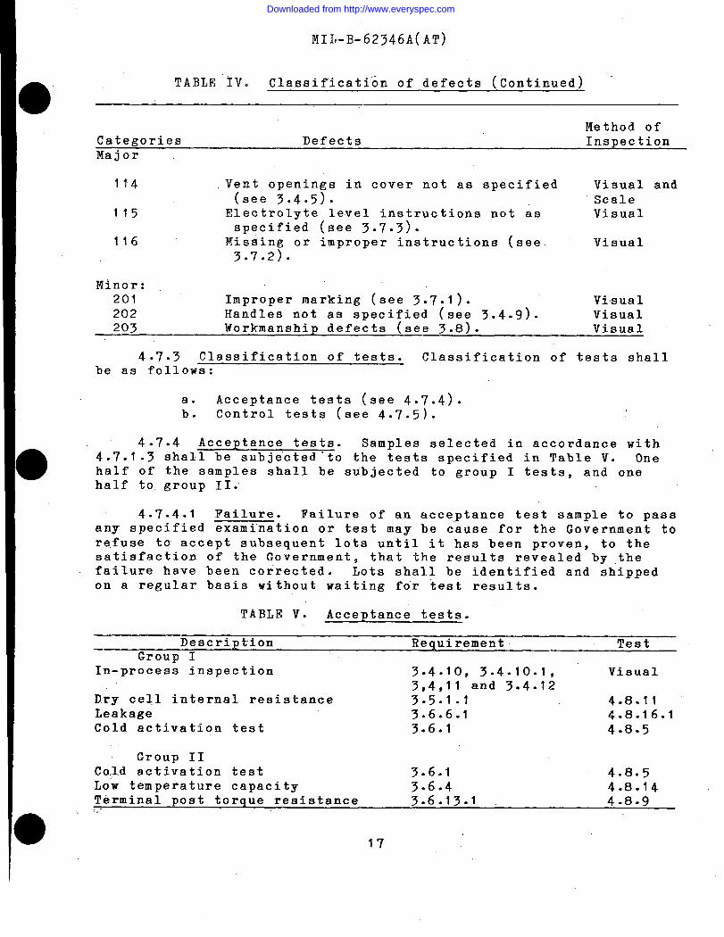
TABLE IV. Classification of defects (Continued) “
Method ofCategories Defects InspectionMajor
114 Vent openings in cover not as specified(see 3.4.5).
Visual andScale
115 Electrolyte level instructions not as Visualspecified (see 3.7.3).
116 Missing or improper instructions (see Visual3.7.2).
Minor:201 Improper marking (see 3.7.1). Visual202 Handles not as specified (see 3.4.9). Visual203 Workmanship defects (see 3.8). Visual
4.7.3 Classification of tests. Classification of tests shallbe as follows:
a. Acceptance tests (see 4.’7.4).b. Control tests (see 4.7.5).
4.7.4 Acceptance tests. Samples selected in accordance with4.7.1.3 shall be subjected ’to the tests specified in Table V. Onehalf of the samples shall be subjected to group I tests, and onehalf to group II.
4.7.4.1 Failure. Failure of an acceptance test sample to passany specified examination or test may be c“ause for the Government torefuse to accept subsequent lots until it has been proven, to thesatisfaction of the Governmentp that the results revealed by thefailure have been corrected. Lots shall be identified and shippedon a regular basis without waiting for test results.
TABLE V. Acceptance tests.
Description Requirement TestGroup I
In-process inspection 3.4910, 3.4.10.1, Visual3,4,11 and 3.4.12
Dry cell internal resistance 3.5.1.1 4.8.11Leakage 3.6.6.1 4.8.16.1Cold activation test 3.6.1 4.8.5
Group 11Co(l.dactivation test 3.6.1 4.8.5Low temperature capacity 3.6.4 4.8.14Terminal post torque resistance 3.6.13.1 4.8.9:.-
17
Downloaded from http://www.everyspec.com

NIL-B-62346A(AT)
4*7.5 Control tests. Control test samples shall be selected.at the rate of two of each 5,000 batteries produced, except that notless than two nor more than four shall be selected in a 30 dayperiod. Samples shall be examined for the defects specified inTable VI.
,’
4.7.5.1 Failure. Failure of a control” test sample to pass any
specified examination or test may be cause for the Government to re-fuse to accept subsequent lots until it has been proven, to the sat-isfaction of the Government? that the faults revealed by the failurehave been corrected. Lots shall be identified and shipped on a regu-lar basis without waiting for test results.
TABLE VI. Control tests
—.—.. ———.— —Description Requirement Test—— .
Vent filler Plugs 3.4.8 – 4.8.7Handles ‘ “ 3*4.9 4.8.8Cold activation 3.6.1 4.8.5Thermal shock 3.6.7 4.8.17Vibration 3.6.8 _ 4.8.18—. ——
4.8 Conformance verification.
4.8.1 Electrical breakdown test for containers. The batterycontainer shall be filled with lead or aluminum shot or fitted witha close fitting mandrel or other electrode to within 1/2 inch of thetop of the lowest point on the sides, ends, or partitions of the con-tainers. An alternating current potential of 100 volts root meansquare (rms) per mil of thickness shall be applied for 15 secondsafter full calculated voltage has been reached. Voltage shall besupplied by a transformer of not less than 1/2 kilovoltampere capa-city, using the electrodes in a manner that will subject each outerwall and inner partition of the container .to the electrode potential.Containers shall subsequently, be examined for leaks, imperfections,or other evidence of perforation or burn-through to” determine,”con-formance to 3.441.
.,, ,,,, . . .
,. ,4.8.2 Acid absorption test’ for containers. Two: &pecim;ns,
each 3 by 3 inches, shall be cut from ’the partitions of the , ‘container. The cut edges shall he neither poli$!e~ n?r sealed’”After being, measured With” calipers and weighe~ ,“inthe’ dry, con~div- .tion at plus 80° + 10”F (26:7” + 6°C),:each sPec$mien: shall be’,immersed in a cov~red vessel containing.,150 cqbid Cent”imeter-s (cc): ofsulfuric acid solution of 1,.500 specific gr&’Vity’at’~O°F (2’&.7”,c)..The Vessel shall be held for 7 days in an oven at 150°” ~ 5°F (65.6.”c+’ 3ec)* At the end of the heating period, the specimens shall be—.rinsed in water and dried on the surface. Specimens shall be
inspected for evidence of cracks or blisters and then measured and’weighed. The percentage increase in dimensions and weight shall be’calculated to determine conformance to 3.4.2.
18 .
Downloaded from http://www.everyspec.com

MIL-B-62346A(AT)
. 4.8.3 Impact resistance test. An undamaged specimen containershall be permitted to rest not less than 24 hours after manufacture.Before testing, the sample shall be conditioned for four hours ateach test temperature.(65.6°C + 2.8*C),
The test shall be conducted in an 150”F + 5°FOOF + 2°F (-17.8”C) and -40”F (-40”C) atmosphere.
Impact r~sistance shali be determined by a 2 pound + 0.05 pound solidsteel ball, used as free falling weight. When test~ng, the height ofdrop necessary to crack the container on the inside opposite the pointof impact is the impact value for that section. The impact resistanceshall be found by dropping the weight at the height necessary to pro-duce the minimum impact resistance requirement for the test tempera-ture (see Table I). The weight shall hit the container only once foreach drop. During the test, the container shall be positioned on aflat steel plate, about an inch longer and wider than the container.The container shall be positioned in such a manner that the ball willstrike one-third down from the top of the container on the centerlineof the sides of each cell and on the centen. of each cell cover area(where thickness is uniform). Testing of post cells, is not required.
4.8.4 Bulge resistance. The bulge resistance of battery con-”tainer shall be determined by test 2, Bulge Characteristics of Stor-age Battery Manufacturing Industry Testing Procedures?, BatteryCouncil International (BCI). The bulges in the container shall bemeasured to determine conformance to 3.4.4.
4.8.5 Cold activation. This test shall apply to batteriesfurnished in charged and dry condition and without supplementarycharge. The battery and electrolyte, 1.280 ~ .005 specific gravityat 80”F (26.7°C) shall be placed in a cold chamber at 30”F ~ 2°F, (-I”C+ I“C) for at least 18 hours prior to test and held until both battery=nd acid are at 30°F ~ 2°F (-I”C ~ I“C). The electrolyte shall conformto 3.2.1. Remove from cold chamber ”and immediately fill the batterywith the cold electrolyte. Allow battery to stand 30 minutes afterfilling last cell. Record specific gravity and temperature of theelectrolyte. Discharge the battery at 450 amperes. Note and recordthe terminal voltage at 60 seconds to determine conformance to 3.6.1.
4.8.6 Battery cover physical characteristics. Battery coversshall be tested as specified in 4.8.1, 4.8.2, and 4.8.3 with appro-
priate modifications in samples and procedures. Results shall be
evaluated as specified in referenced paragraphs to determine con-formance to 3.3.2.
19
Downloaded from http://www.everyspec.com

MIL-EI-62346A(AT)
I ,,4.8.7 Vent filler plug thermal and pressure resistance test. ‘
To determine conformance to 3.4.8, each vent filler plug from thebattery under test shall be placed in an ambient air temperature ofminus. 65” + 2°F (-54°C + I“C) for 2 hours. At the end of the cool-ing pe’riod~ the plugs s~all be removed and immediately placed in anoven at an ambient air temperature of plus 2!50° I 5°F (121°C ~ 3“C)for 90 minutes. The plugs shall then be removed and inspected forevidence of damage such as cracking or melting. After a coolingperiod of 1 hour, each vent filler plug shall be inserted in a fix-turle arranged so that water pressure can be applied on the upper sideof the plug~ and air pressure on the lower side. Using this fixture,the upper.side of each plug shall be subjected to a water pressurewhich exceeds the air pressure on the lower side by 1.75 psi (waterhead of 4 feet, if air pressure is atmospheric). The number of dropsof water that leak through each vent filler plug and the time re-quired therefore (not to be less than one minute) shall be recorded.The water pressure shall then be released and the air pressure on thelower side” increased to 0.5 psi above the pressure existing on theupper side. Plug shall open under specified pressure.
4.8.8 Handle test. The handle and bond areas shall be satu-rated with electrolyte conforming to 3.2.I and air dried twice dailyfor two days. The handles and bond areas shall again be saturated.The battery shall then be placed in an ambient air temperature of plus190° + 2°F (88” + l“C) for 60 minutes, allowed to cool to room tem-perature, and ag~in heated at 190° + 2°F (88” + l“C) for 60 minutes.The battery shall then be removed f~om the eve= and immediately placedin a test fixture similar to Figure 1 . The battery shall be ini- atially set on the removable support, and the angles and initial taut-ness of the handles shall be set with the support in place. Theballast weight equal to the weight of the test battery shall be placedon top of the test battery (a second similar battery may be used).“The support shall then be slowly removed and the battery and weight beallowed to hang freely by the handles for 60 seconds. The batteryshall then be removed and the handles and bond shall be examined forconformance to 3.4.9.
After the test, the battery shall be placed in an ambient air tem-perature of minus 65” ~ 2°F (-54° + lC”) for 24 hours. The batteryshall be removed from the cold box—and immediately subjected to thehandle test previously specified.
At the conclusion. of the test, the handles and bond shall be examinedfor conformance with 3.4.9.
20
Downloaded from http://www.everyspec.com

MIL-Br62346A(AT)
r 45° + 1° -Both S~des 7
Turnbuckle(See Note 3 See Note
umort
2
1
(See Note 1.)”
NOTES: 1. Support shall allow gradual and even removal so as tominimize shock and insure even loading of both handles.
2. A lightweight (less than 2 lbs. or 1 kg) shim may beused between battery and weight to prevent damage to caps,posts, or cover.
3. Turnbuckles shall be used to establish 45° angle ofhandles with test weight applied after removal of support.Turnbuckles shall include a device to support rope handlesover a length of 4% in~hes (l14mm) during test.
FIGURE 1. Handle test
20A
Downloaded from http://www.everyspec.com
MIL-B-62346A(AT)
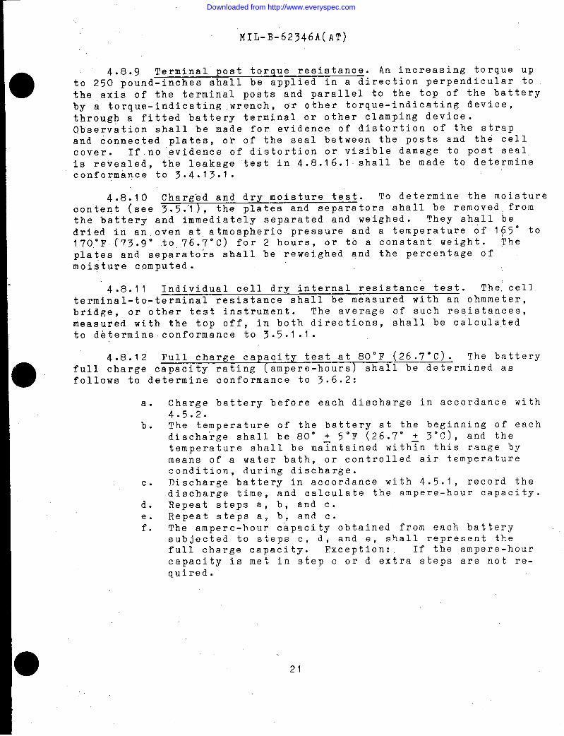
4.8.9 Terminal post torque resistance. An increasing torque upto 250 pound-inches shall be applied in a direction perpendicular tothe axis of the terminal posts and parallel to the top of the batteryby a torque-indicating .wrench, or other torque-indicating device,
through a fitted battery terminal or other clamping device.Observation shall be made for evidence of distortion of the strapand connected plates, or of the seal between the posts and the cellcover. If.no ‘evidence of distortion or visible damage to post sealis revealed, the leakage test in 4.8.16.1 shall be made to determineconformance to 3.4.13.1.
4.8.10 Charged and dry moisture test. To determine the moisturecontent (see 3.5.”1), the plates and separators shall be removed. fromthe battery and immediately separated and weighed. They shall bedried in an oven at atmospheric pressure and a temperature of 165° to170”F(73.9° .to,76.7°C) for 2 hours, or to a constant weight. Theplates and separators shall be reweighed and the percentage ofmoisture computed.
4.8.11 ~ internal resistance test. The, cellterminal-to-terminal resistance shall be measured with an ohmmeter,bridge, or other test instrument. The average of such resistances,measured with the top off, in both directions, shall be calculatedto determine conformance to 3.5.1.1.
4.8.12 Full charge capacity test at 80°F (26.7”C). The batteryfull charge capacity rating (ampere-hours) shall be determined asfollows to determine conformance to 3.6.2:
a.
b.
c.
d.e.f*
Charge battery before each discharge in accordance with4.5.2.The temperature of the battery at the beginning of eachdischarge shall be 80° + 5°F (26.7° + 3°C), and thetemperature shall be ma~ntained with~n this range bymeans of a water bath, or controlled air temperaturecondition, during discharge.Discharge battery in accordance with 4.5.1, record thedischarge time, and calculate the ampere-hour capacity.Repeat steps a, b, and c.Repeat steps a, b, and c.The ampere-hour capacity obtained from each batterysubjected to steps c, d, and e, shall represent thefull charge capacity. Exception: If the ampere-hourcapacity is met in step c or d extra steps are not re-quired.
21
Downloaded from http://www.everyspec.com

MIL-B-62346A(AT)
4.8.13conducted as
a.
b.
c.
d.e.f.
Reserve capacity test. Reserve capacity tests shall befollows to determine conformance to 3.6.3:
Charge battery before each discharge in accordancewith 4.5.2.The temperature of the battery at the beginning ofeach discharge shall be 80” s 5°F (26.7” ~ 3°C), andthe temperature shall be maintained within this raugeby means of a water bath, or controlled air tempera-ture condition, during discharge.Discharge battery at 25 + 0.25 amperes to a terminalvoltage of 10.5 volts. ~ecord the time of dischargein minutes.Repeat steps a, h, and c.Repeat steps a, b, and c.
,,
The longest time- of discharge obtained from eachbattery subjected to steps c, d, and e shall representthe reserve capacity of the battery. Exception: Ifthe reserve capacity requirement is met in step c orstep d, step e is not required.
The following correction factor shall be used to compensate forelectrolyte temperature variation from the stabilized 80° J 5°F (26.7: 3°c).
Mc = Mr (fl - 0.005 (Tf - 80)).Mc = Corrected minutes.Mr = Minutes run.Tf = Temperature at one end of discharge, “F ~/.0.005 = Temperature correction factor.
1/ Results not valid if electrolyte temperature is above 90°F—(32.3°C) or below 70”F (21°C) at completion of test.
4.8.14 Low temperature capacity test. The test for high dis-charge rate at O“F (-17.8°C) and minus 40”F (-40”C) shall be per-formed as follows to determine conformance to 3.6.4:
a. Charge battery in accordance with 4.5.2.be Place battery in cold chamber having a temperature of
minus 40° + 2°F.co When the e~ectrolyte has stabilized for one hour at
minus 40° + 2“F and immediately upon removal from thecold chamb=r the battery shall be discharged at 350amperes until the battery reaches a terminal voltage of7.2 vOlts.
22
Downloaded from http://www.everyspec.com
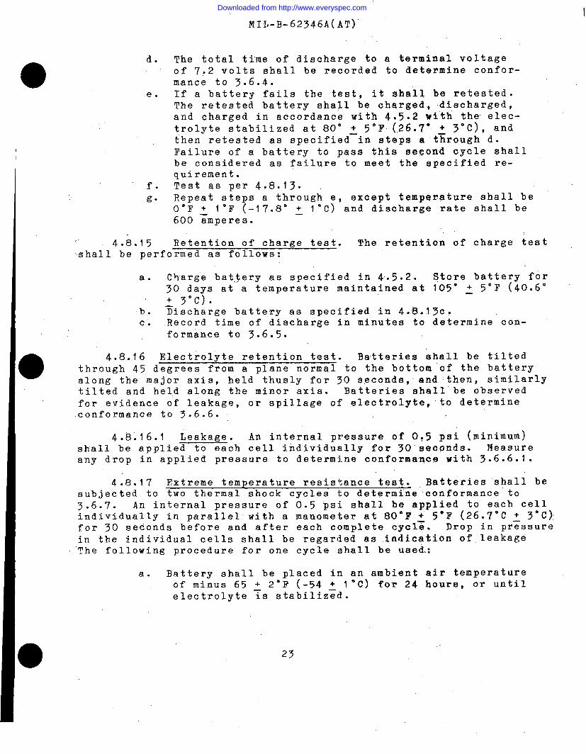
d.
e.
,. 4.8.15
MIL-B-62346A(AT)”
The total time of discharge to a terminal voltageof 7:2 volts shall be recorded to determine confor-mance to 3.6.4.If a battery fails the test, it shall be retested.The retested battery shall be charged, discharged,and charged in accordance with 4.5.2 wi”th the elec-trolyte stabilized at 80” + 5°F (.26.7” ~ 3“C), andthen retested as specified–in steps a through d.Failure of a battery to pass this se$ond cycle shallbe considered as failure to meet the specified re-quirement.Test as per 4.8.13.Repeat steps a through e, except temperature shall beOOF ~ l°F (-17.8° ~ I“C) and discharge rate shall be600 amperes.
Retention of charge test. The retention of charge testshall be performed as follows:
a. Charge batjery as specified in 4.5.2. Store battery for30 days at a temperature maintained at 105” j 5°F (40.6°
+ 3“C).b. ~ischarge battery as specified in 4.8.13c.c. Record time of discharge in minutes to determine con-
formance to 3.6.5.
4.8.16 Electrolyte retention test. Batteries shall be tiltedthrough 45 degrees from a plane normal to the bottom of the batteryalong the major axis, held thusly for 30 seconds, and then, similarlytilted and held along the minor axis. Batteries shall’ be observedfor evidence of leakage, or spillage of electrolyte, to determineconformance to 3.6.6.
4.8.16.1 Leakage. An internal pressure of 005 psi (minimum)shall be applied to each cell individually for 30 seapnds. Measureany drop in applied pressure to determine conformance with 3.6.6.1.
4.8.17 Extreme temperature resistance test.. Batteries “shall besubjected to two thermal shock cycles to determine conformance to3.’6.7. An internal pressure of 0.5 psi shall be appl$ed to each cellindividually in parallel with a manometer at 80”F + 5°F (26.7°C ~ 3“C):for 30 seconds before and after each complete cycl~. Drop in pressurein the individual cells shall be regarded as indication of leakage“’Thefollowing procedure for one cycle shall be used:
a. Battery shall be placed in an ambient air temperatureof minus 65 + 29F (-54 + 1°C) for 24 hours, or untilelectrolyte ~s stabiliz~d.
23
Downloaded from http://www.everyspec.com

MIL-B-62346A(AT)
b.
C*
4.8.18subjected to
The battery, shall be then placed in an, ambient airtemp.eraturq of190°F ~ 2°F (87.8 ~ l“C) for 24 “ ,,hours.The battery shall be allowed to cool gradually to 80”.+ IO”,F (26.7 + 6“c) for 24 hours.—.
Vibration resistance test. The test specimen shall be4.8.13a, b, and c and stabilized in an ambient air tem-
perature of 80°~.100F (26.7° + 6“C) prior to vibration. Apparatusshall include a hold-down .fram= to bear on the top edges of thebattery container, but not on the vent plugs or terminal posts.While in an ambient air temperature of 80° + IO”F (26;7° + 6°C), andmounted in the vibrating rnachine$ the speci~en shall be v~brated for 2hours at a frequency of “2000 to 2100 cycles per minute through anamplitude of 0.045 to 0.050 inch ”(total excursion 0.090 to 0.100inch) . During this test the battery shall be discharged at t$he20-hour rate. The test shall be repeated for one hour, except that thebattery shall be chilled to, and the electrolyte stabilized at, a tem-perature of minus 40° + 2°F (-40° ~ 2“C) for one hour immediatelybefore beginning vibra~i.on.: During the test, the battery shall beobserved for maintenance of steady voltage and current, and thereafterexamined for evidence of loosening of terminal posts in the covers andflooding of electrolyte at the top. The battery shall be removed. fromthe ,vibrating machine, allowed to warm to 80” ~ IO”F (26.7” + 6“c)until the electrolyte is stabilized, then subjected to 4.8.lTa, b, and
After testing the battery shall be disassembled and examined for~~mage to detemyine conformance to 3.6.8.
4.8.19 Lifa-cycle capacity tests. ,Life tests shall consist of a 9series of cycles of discharge and charge in accordance with the appli-cable test specified in 4.8.19.1. Immediately prior to the begin~~ngof the test, the battery shall be fully charged as specified in 4.5.2.Tests shall be performed with the batteryiri a water ba$h, with thetemperature maintained at1,00’~ 5°F (37.8 “i~”,c)i. waterg hallbe:,added as required to:each, cell to replace e~aporatton (except, duringthe capacity discharge test cycle for, ampere-hour capacity),:. .,When ‘theampere-hour capacity equals,or drops beiow 40 percent,,of the raied”,:,,ampere -hour capacity during the ,capacity discharge test cycle,,,the ~~battery shall be, fusly qharged,as specified in’ 4.5.2 and ’tested,as :,specified in4.8.12. If thecapacity”~s above,40 percent, of normal:, ,,full-charge value, the Iife’ test stiail ‘be continued. If.the capacityequals or falls below 40 percent,,,,the life cycle test. shall:-be te,r-,;minated: The life “cycle .attained’~y a battery shallbe taken’a’s’thetotal of the actual cycles completed on “the life t’est, plus’”each’’cyclereceived on other tests.
24
Downloaded from http://www.everyspec.com

MI L-B-62346 A(AT)
4.8.19.1 Life-capacity discharge cycles. To determine con-formance to 3.6.9, the test shall consist of a ‘total of 235discharge/charge cycles including normal and weekly cycles and cyclesattained on other tests:
a. Normal cycles. The normal cycles shall consist of aseries of 6-hour cycles (4 cycles per day orapproximately 24 per week) . Each cycle shall consist ofdischarge for 1.hour at 40 amperes and charge for 5hours at 10 amperes.
b. Weekly capacity discharge cycles. Ampere-hour capacityshall be determined at the completion of each seriesof 24 normal cycles. The battery shall be dischargedat the ampere rate for normal cycles, until a finalaverage terminal voltage of 1 .75 volts per cell hasbeen reached. The ampere-hour capacity shall becalculated as the product of the current rate inamperes and the time o,f discharge in hours. Followingthis discharge, the battery shall be fully chargedper SAE J537 and the normal cycle procedure shallbe continued. The bat”tery shall be placed on a dis-charge cycle which, with the charge cycle, shall con-stitute a full normal cycle.
4.8.20 Storage life test. Specimens shall be stored understandard test conditions (4.4.1) for 90 days. After storage thebattery shall be tested per 4.8.5 to determine conformance to 3.6.10.
,’
4.8.21 Inspection of packaging. Packaging inspection shallbeaccomplished in accordance with the quality assurance provisions o.fMIL-B-208, and the applicable packaging data sheet.
5. PACKAGING.,
5.1 Dry and wet charged batteries. “—
5.1.1 Preservation, packaging, packing, and marking” Unlessotherwise specified, charged wet and dry batteries shall be cleaned,dried, ,preserved, packaged, packed and marked in’ accordance with theapplicable packaging standard, and packaging data sheet? for thedesired level of protection. ‘Marking shall be i.n accordance withMIL-STD-129, including lot numbers, except for any special markingrequirements (see 6.2).
5.1.2 Transportation (charged and wet batteries). Charged andwet batteries shall be transported in conformance to PoT Regulation49 CFR.
25
Downloaded from http://www.everyspec.com

MII,-B-62346A(AT)
6. NOTES
6.1 Intended use. Batteries covered hy this specification areintended primarily for starting, lighting, and ignition service inmilitary vehicles including tactical and administrative vehicles,internal combustion engine driven industrial trucks and tractors,construction equipment and generator sets. The batteries will alsobe used for radio operation and as a source of electrical energy foroperating vehicular accessories, such as sighting devices’ and controlmechanisms.
.,
6.2 Ordering data. Procurement documents should specify thefollowing:
a. Title, number, and date of this specification.b. Battery condition (see 3.5).c. Any special marking requirements (see 5.1.1).d. Level of preservation and packaging, level of packing
required (see 5.1.1).
6.3 Qualification. Qualification samples shall be tested andapproved under the appropriate provisions of 7-104.55 of the DefenseAcquisition Regulation. The contracting officer should includespecific instructions in all procurement instruments regarding ar-rangements for examination, tests and approval of the qualification(see 3.1).
6.4 Recycled materials. The use of recycled materials whichmeet the requirements of the applicable material specifications with-out jeopardizing the intended use of the item shall be encouraged(see 3.2).
Custodian:Army - AT
Preparing activity:Army - AT
Project No. 6140-A582
i
26
Downloaded from http://www.everyspec.com