Miguel José Magalhães Lopes
251
Miguel José Magalhães Lopes outubro de 2013 A Mid-Level Framework for Independent Network Services Configuration Management Universidade do Minho Escola de Engenharia
Transcript of Miguel José Magalhães Lopes

Miguel José Magalhães Lopes
outubro de 2013
UM
inho
|201
3
A Mid-Level Framework for IndependentNetwork Services Configuration Management
Universidade do Minho
Escola de Engenharia
Mig
uel J
osé
Mag
alhã
es L
opes
A M
id-L
eve
l Fra
mew
ork
fo
r In
de
pe
nd
en
tN
etw
ork
Se
rvic
es
Co
nfi
gu
rati
on
Ma
na
ge
me
nt
outubro de 2013
Dissertação apresentada às Universidades de Minho, Aveiro e
Porto para cumprimento dos requisitos necessários à obtenção
do grau de Doutor no âmbito do doutoramento conjunto MAP-Tele,
realizada sob a orientação científica do Doutor Bruno Dias,
Professor Auxiliar do Departamento de Informática da
Universidade do Minho e do Doutor Antonio Costa, Professor
Auxiliar do Departamento de Informática da Universidade do
Minho.
Miguel José Magalhães Lopes
A Mid-Level Framework for IndependentNetwork Services ConfigurationManagement
Universidade do Minho
Escola de Engenharia
Programa Doutoral em Telecomunicaçãoesdas Universidades do Minho, de Aveiro e do Porto
Universidade do Minho
universidade de aveiro

Acknowledgements
I would like to thank to my PhD advisors Professor Bruno Dias and Professor AntonioCosta. I would like to thank you for encouraging my research and for allowing me togrow as a research scientist. Your advice on both research as well as on my career havebeen invaluable. I would also like to thank Professor Alexandre Santos hose advises wereessential for the realization of this project.
A special appreciation to the Department of Informatics of the School of Engineering ofthe University of Minho for providing all the logistics required.
Finally I want to thank my parents, dear wife Sonia and my son Miguel, hose love wasmy support and motivation.
i

ii

Abstract
Decades of evolution in communication network’s resulted in a high diversity of solutions,not only in terms of network elements but also in terms of the way they are managed.From a management perspective, having heterogeneous elements was a feasible scenarioover the last decades, where management activities were mostly considered as additionalfeatures. However, with the most recent advances on network technology, that includesproposals for future Internet as well as requirements for automation, scale and efficiency,new management methods are required and integrated network management became anessential issue.
Most recent solutions aiming to integrate the management of heterogeneous networkelements, rely on the application of semantic data translations to obtain a common rep-resentation between heterogeneous managed elements, thus enabling their managementintegration. However, the realization of semantic translations is very complex to be effec-tively achieved, requiring extensive processing of data to find equivalent representation,besides requiring the administrator’s intervention to create and validate conversions,since contemporary data models lack a formal semantic representation.
From these constrains a research question arose: Is it possible to integrate the config-uration management of heterogeneous network elements overcoming the use of manage-ment translations? In this thesis the author uses a network service abstraction to proposea framework for network service management, which comprehends the two essential man-agement operations: monitoring and configuring. This thesis focus on describing andexperimenting the subsystem responsible for the network services configurations man-agement, named Mid-level Network Service Configuration (MiNSC), being the thesismost important contribution.
The MiNSC subsystem proposes a new configuration management interface for in-tegrated network service management based on standard technologies that includes anuniversal information model implemented on unique data models. This overcomes theuse of management translations while providing advanced management functionalities,only available in more advanced research projects, that includes scalability and resilienceimprovement methods. Such functionalities are provided by using a two-layer distributedarchitecture, as well as over-provisioning of network elements. To demonstrate MiNSC’smanagement capabilities, a group of experiments was conducted, that included, configu-ration deployment, instance migration and expansion using a DNS management systemas test bed.
iii

Since MiNSC represents a new architectural approach, with no direct reference fora quantitative evaluation, a theoretical analysis was conducted in order to evaluate itagainst important integrated network management perspectives. It was concluded thatthere is a tendency to apply management translations, being the most straightforward so-lution when integrating the management of heterogeneous management interfaces and/ordata models. However, management translations are very complex to be realized, beingits effectiveness questionable for highly heterogeneous environments. The implemen-tation of MiNSC’s standard configuration management interface provides a simplifiedperspective that, by using universal configurations, removes translations from the man-agement system. Its distributed architecture uses independent/universal configurationsand over-provisioning of network elements to improve the service’s resilience and scala-bility, enabling as well a more efficient resource management by dynamically allocatingresources as needed.
iv

Contents
Acronyms xvii
1 Introduction 1
1.1 Motivation . . . . . . . . . . . . . . . . . . . . . . . . . . . . . . . . . . . 1
1.2 Objectives of this Thesis . . . . . . . . . . . . . . . . . . . . . . . . . . . . 4
1.3 Contributions of this Thesis . . . . . . . . . . . . . . . . . . . . . . . . . . 7
1.4 Document Organization . . . . . . . . . . . . . . . . . . . . . . . . . . . . 9
2 Network Management Landscape 11
2.1 Open Systems Interconnection (OSI) - Network Management . . . . . . . 11
2.1.1 Information Model . . . . . . . . . . . . . . . . . . . . . . . . . . . 12
2.1.2 Communication Model . . . . . . . . . . . . . . . . . . . . . . . . . 14
2.1.3 Functional Model . . . . . . . . . . . . . . . . . . . . . . . . . . . . 14
2.2 Internet-standard Network Management Framework (INMF) . . . . . . . 15
2.2.1 Architecture . . . . . . . . . . . . . . . . . . . . . . . . . . . . . . 16
2.2.2 Information Model . . . . . . . . . . . . . . . . . . . . . . . . . . . 16
2.2.3 Communication Model . . . . . . . . . . . . . . . . . . . . . . . . . 17
2.2.4 Terminology . . . . . . . . . . . . . . . . . . . . . . . . . . . . . . 18
2.2.5 Additional Considerations . . . . . . . . . . . . . . . . . . . . . . . 19
v

CONTENTS
2.3 Common Object Request Broker Architecture (CORBA) - Network Man-
agement . . . . . . . . . . . . . . . . . . . . . . . . . . . . . . . . . . . . . 22
2.3.1 Architecture . . . . . . . . . . . . . . . . . . . . . . . . . . . . . . 23
2.3.2 Information Model . . . . . . . . . . . . . . . . . . . . . . . . . . . 25
2.3.3 Communication Model . . . . . . . . . . . . . . . . . . . . . . . . . 26
2.3.4 Functional Model . . . . . . . . . . . . . . . . . . . . . . . . . . . . 26
2.3.5 Additional Considerations . . . . . . . . . . . . . . . . . . . . . . . 27
2.4 Web-Based Enterprise Management (WBEM) . . . . . . . . . . . . . . . . 28
2.4.1 Architecture . . . . . . . . . . . . . . . . . . . . . . . . . . . . . . 29
2.4.2 Common Information Model (CIM) . . . . . . . . . . . . . . . . . 30
2.4.3 Communication Model . . . . . . . . . . . . . . . . . . . . . . . . . 31
2.4.4 Additional Considerations . . . . . . . . . . . . . . . . . . . . . . . 32
2.5 Network Configuration Protocol (NETCONF) . . . . . . . . . . . . . . . . 32
2.5.1 Architecture . . . . . . . . . . . . . . . . . . . . . . . . . . . . . . 33
2.5.2 Information Model . . . . . . . . . . . . . . . . . . . . . . . . . . . 33
2.5.3 Communication Model . . . . . . . . . . . . . . . . . . . . . . . . . 34
2.5.4 Additional Consideration . . . . . . . . . . . . . . . . . . . . . . . 34
2.6 Future Internet Management . . . . . . . . . . . . . . . . . . . . . . . . . 37
2.7 Other Network Management Solutions . . . . . . . . . . . . . . . . . . . . 42
2.8 Conclusion . . . . . . . . . . . . . . . . . . . . . . . . . . . . . . . . . . . 42
3 Automated, Distributed and Integrated Network Services Manage-
ment 45
3.1 Motivation . . . . . . . . . . . . . . . . . . . . . . . . . . . . . . . . . . . 45
3.2 Integrated Network Management . . . . . . . . . . . . . . . . . . . . . . . 47
3.3 Management Translations’ Taxonomy . . . . . . . . . . . . . . . . . . . . 47
3.4 Intermediary Network Management Translation . . . . . . . . . . . . . . . 49
vi

CONTENTS
3.4.1 Management Information Translation . . . . . . . . . . . . . . . . 49
3.4.2 Management Protocol Translation . . . . . . . . . . . . . . . . . . 49
3.4.3 Implications . . . . . . . . . . . . . . . . . . . . . . . . . . . . . . . 50
3.5 Integrated Network Service Management Requirements . . . . . . . . . . . 51
3.5.1 Network Service Definition . . . . . . . . . . . . . . . . . . . . . . 53
3.5.2 Network Management Activities . . . . . . . . . . . . . . . . . . . 55
3.5.3 Automation and Distribution . . . . . . . . . . . . . . . . . . . . . 57
3.5.4 Automated and Distributed Network Service Monitoring (SMON) 60
3.5.5 Mid-Level Network Service Configuration Management (MiNSC) . 61
3.6 Conclusion . . . . . . . . . . . . . . . . . . . . . . . . . . . . . . . . . . . 61
4 MiNSC: Mid-level Network Services Configuration Management 63
4.1 Motivation . . . . . . . . . . . . . . . . . . . . . . . . . . . . . . . . . . . 63
4.2 Integrated Network Service Management . . . . . . . . . . . . . . . . . . . 64
4.3 Architecture . . . . . . . . . . . . . . . . . . . . . . . . . . . . . . . . . . . 66
4.3.1 Network Service Instance Management Layer . . . . . . . . . . . . 66
4.3.2 Service Management Layer . . . . . . . . . . . . . . . . . . . . . . 70
4.3.3 Configuration Agent . . . . . . . . . . . . . . . . . . . . . . . . . . 73
4.3.4 Configuration Management Protocol . . . . . . . . . . . . . . . . . 74
4.3.5 Security . . . . . . . . . . . . . . . . . . . . . . . . . . . . . . . . . 85
4.4 Functional Model . . . . . . . . . . . . . . . . . . . . . . . . . . . . . . . . 89
4.4.1 Network Service Instance Management Layer . . . . . . . . . . . . 90
4.4.2 Service Management Layer . . . . . . . . . . . . . . . . . . . . . . 90
4.4.3 Server and Instance Configuration Replication . . . . . . . . . . . 93
4.4.4 Database Synchronization . . . . . . . . . . . . . . . . . . . . . . . 95
4.4.5 Network Service Deployment . . . . . . . . . . . . . . . . . . . . . 96
4.4.6 Service Expansion . . . . . . . . . . . . . . . . . . . . . . . . . . . 97
vii

CONTENTS
4.4.7 Server and Instance Serialization . . . . . . . . . . . . . . . . . . . 98
4.5 Resilience Improvement Method . . . . . . . . . . . . . . . . . . . . . . . 99
4.5.1 Over-provisioning . . . . . . . . . . . . . . . . . . . . . . . . . . . . 100
4.5.2 Cost-aware Management . . . . . . . . . . . . . . . . . . . . . . . . 100
4.6 Final Remarks . . . . . . . . . . . . . . . . . . . . . . . . . . . . . . . . . 101
4.6.1 Standard Management Information Models . . . . . . . . . . . . . 101
4.6.2 Integrated Network Management . . . . . . . . . . . . . . . . . . . 104
4.6.3 Confidentiality . . . . . . . . . . . . . . . . . . . . . . . . . . . . . 105
4.6.4 Service Mobility . . . . . . . . . . . . . . . . . . . . . . . . . . . . 105
4.7 Conclusion . . . . . . . . . . . . . . . . . . . . . . . . . . . . . . . . . . . 106
5 Implementation and Results 107
5.1 Motivation . . . . . . . . . . . . . . . . . . . . . . . . . . . . . . . . . . . 107
5.2 Architecture . . . . . . . . . . . . . . . . . . . . . . . . . . . . . . . . . . . 108
5.2.1 Configuration Management Server . . . . . . . . . . . . . . . . . . 108
5.2.2 Configuration Management Agent . . . . . . . . . . . . . . . . . . 112
5.3 Development Tools . . . . . . . . . . . . . . . . . . . . . . . . . . . . . . . 114
5.3.1 MIB Designer . . . . . . . . . . . . . . . . . . . . . . . . . . . . . . 115
5.3.2 AgenPro . . . . . . . . . . . . . . . . . . . . . . . . . . . . . . . . . 115
5.3.3 SNMP4j . . . . . . . . . . . . . . . . . . . . . . . . . . . . . . . . . 116
5.4 Prototype Development . . . . . . . . . . . . . . . . . . . . . . . . . . . . 117
5.4.1 DNS Management Information Models . . . . . . . . . . . . . . . . 117
5.4.2 Configuration Management Server . . . . . . . . . . . . . . . . . . 125
5.4.3 Configuration Management Agent . . . . . . . . . . . . . . . . . . 141
5.5 Experiments . . . . . . . . . . . . . . . . . . . . . . . . . . . . . . . . . . . 144
5.5.1 DNS Instance Configuration . . . . . . . . . . . . . . . . . . . . . . 144
5.5.2 DNS Management Evaluation . . . . . . . . . . . . . . . . . . . . . 147
viii

CONTENTS
5.5.3 DNS Instance Configuration Replication . . . . . . . . . . . . . . . 149
5.5.4 DNS Service Deployment . . . . . . . . . . . . . . . . . . . . . . . 152
5.5.5 DNS Instance Execution Migration . . . . . . . . . . . . . . . . . . 155
5.5.6 DNS Instance Expansion . . . . . . . . . . . . . . . . . . . . . . . 162
5.6 Conclusion . . . . . . . . . . . . . . . . . . . . . . . . . . . . . . . . . . . 165
6 Evaluation 167
6.1 Motivation . . . . . . . . . . . . . . . . . . . . . . . . . . . . . . . . . . . 167
6.2 Automation . . . . . . . . . . . . . . . . . . . . . . . . . . . . . . . . . . . 168
6.3 Configuration Management Provisioning . . . . . . . . . . . . . . . . . . . 175
6.4 Heterogeneity . . . . . . . . . . . . . . . . . . . . . . . . . . . . . . . . . . 179
6.5 Interoperability . . . . . . . . . . . . . . . . . . . . . . . . . . . . . . . . . 182
6.6 Management Information & Data Models . . . . . . . . . . . . . . . . . . 185
6.7 Resilience . . . . . . . . . . . . . . . . . . . . . . . . . . . . . . . . . . . . 188
6.8 Scalability . . . . . . . . . . . . . . . . . . . . . . . . . . . . . . . . . . . . 191
6.9 Summary of Comparative Analysis . . . . . . . . . . . . . . . . . . . . . . 194
6.10 Limitations . . . . . . . . . . . . . . . . . . . . . . . . . . . . . . . . . . . 195
6.11 Conclusion . . . . . . . . . . . . . . . . . . . . . . . . . . . . . . . . . . . 196
7 Conclusion 199
7.1 Motivation . . . . . . . . . . . . . . . . . . . . . . . . . . . . . . . . . . . 199
7.2 Main Contributions . . . . . . . . . . . . . . . . . . . . . . . . . . . . . . . 200
7.3 Overall Conclusions . . . . . . . . . . . . . . . . . . . . . . . . . . . . . . 203
7.4 Future Work . . . . . . . . . . . . . . . . . . . . . . . . . . . . . . . . . . 205
Bibliography 207
ix

x

List of Figures
2.1 CORBA’s submodules interaction . . . . . . . . . . . . . . . . . . . . . . . 24
3.1 RFC 3139 integrated network management model . . . . . . . . . . . . . . 48
3.2 Conceptualization of a Network Service . . . . . . . . . . . . . . . . . . . 54
3.3 Network services domain including management . . . . . . . . . . . . . . . 56
3.4 Automated, Distributed and Integrated Network Services Management . . 59
3.5 Automated and Distributed Network Service Monitoring . . . . . . . . . . 60
4.1 MiNSC’s network service management model . . . . . . . . . . . . . . . . 65
4.2 MiNSC’s deployment scenario . . . . . . . . . . . . . . . . . . . . . . . . . 67
4.3 MiNSC’ service management architecture . . . . . . . . . . . . . . . . . . 68
4.4 Network Service Instance Management layer functionalities graph . . . . . 90
4.5 Service Management layer functionalities graph . . . . . . . . . . . . . . . 92
5.1 MiNSC’s configuration management server structure . . . . . . . . . . . . 109
5.2 MiNSC’s configuration management agent structure . . . . . . . . . . . . 113
5.3 MiNSC’s DNS management architecture . . . . . . . . . . . . . . . . . . . 117
5.4 DNS instance management information model . . . . . . . . . . . . . . . . 119
5.5 DNS instance management MIB . . . . . . . . . . . . . . . . . . . . . . . 121
5.6 DNS service management information model . . . . . . . . . . . . . . . . 123
5.7 DNS service management MIB . . . . . . . . . . . . . . . . . . . . . . . . 125
xi
LIST OF FIGURES
5.8 Server and Instance Registration MIB . . . . . . . . . . . . . . . . . . . . 126
5.9 Service Replication MIB . . . . . . . . . . . . . . . . . . . . . . . . . . . . 127
5.10 DNS Parameters MIB . . . . . . . . . . . . . . . . . . . . . . . . . . . . . 130
5.11 Monitoring MIB . . . . . . . . . . . . . . . . . . . . . . . . . . . . . . . . 131
5.12 Instance replication MIB . . . . . . . . . . . . . . . . . . . . . . . . . . . . 142
5.13 DNS instance configuration replication . . . . . . . . . . . . . . . . . . . . 150
5.14 DNS service deployment . . . . . . . . . . . . . . . . . . . . . . . . . . . . 153
5.15 Lossy DNS instance execution migration . . . . . . . . . . . . . . . . . . . 156
5.16 Lossless DNS instance execution migration . . . . . . . . . . . . . . . . . . 159
5.17 DNS instance expansion . . . . . . . . . . . . . . . . . . . . . . . . . . . . 163
xii
List of Tables
4.1 Configuration management protocols evaluation . . . . . . . . . . . . . . . 76
5.1 DNS management tools features evaluation . . . . . . . . . . . . . . . . . 148
5.2 DNS instance configuration replication . . . . . . . . . . . . . . . . . . . . 151
5.3 DNS service deployment . . . . . . . . . . . . . . . . . . . . . . . . . . . . 154
5.4 Lossy DNS instance execution migration . . . . . . . . . . . . . . . . . . . 157
5.5 Lossless DNS instance execution migration . . . . . . . . . . . . . . . . . . 161
5.6 DNS instance expansion . . . . . . . . . . . . . . . . . . . . . . . . . . . . 164
6.1 Integrated network management evaluation . . . . . . . . . . . . . . . . . 169
xiii

xiv

List of Algorithms
1 DNS service deployment . . . . . . . . . . . . . . . . . . . . . . . . . . . . 132
2 Lossy DNS instance execution migration . . . . . . . . . . . . . . . . . . . 134
3 Lossless DNS instance execution migration . . . . . . . . . . . . . . . . . . 136
4 DNS instance expansion . . . . . . . . . . . . . . . . . . . . . . . . . . . . 138
5 Instances serialization . . . . . . . . . . . . . . . . . . . . . . . . . . . . . 139
6 Generation of active DNS instance configuration . . . . . . . . . . . . . . 140
7 Generation of candidate DNS instance configuration . . . . . . . . . . . . 140
xv

xvi

Acronyms
4WARD Architecture and Design for the Future Internet
6LoWPAN IPv6 over Low Power Wireless Personal Area Network
ABE Aggregate Business Entity
ACL Access Control List
ACS Active Configuration Server
ACSE Association Control Service Element
AD Active Decision
AE Autonomic Element
AES Advanced Encryption Standard
AMS Active Monitoring Server
API Application Programming Interface
ARP Address Resolution Protocol
ASI Active Service Instance
ASN.1 Abstract Syntax Notation One
ATM Asynchronous Transfer Mode
AUTOI Autonomic Internet
BEEP Blocks Extensible Exchange Protocol
BER Basic Encoding Rules
xvii

Acronyms
CCS Candidate Configuration Server
CBC Cipher Block Chaining
CIM Common Information Model
CIMOM Common Information Model Object Manager
CLI Command Line Interface
CMIP Common Management Information Protocol
CMIS Common Management Information Services
COPS Common Open Policy Service
COPS-PR Common Open Policy Service - Policy Provisioning
CORBA Common Object Request Broker Architecture
CPS Configuration Pointing Server
CPU Central Processing Unit
CSI Candidate Service Instance
DEN Directory Enabled Networks
DEN-ng Directory Enabled Networks-next generation
DES Data Encryption Standard
DHCP Dynamic Host Configuration Protocol
DIFFSERV Differentiated Services
DMTF Desktop Management Task Force
DNS Domain Name Service
DoS Denial of Service
DTD Document Type Definition
DTLS Datagram Transport Layer Security
FCAPS Fault, Configuration, Accounting, Performance and Security
xviii
Acronyms
FIND Future Internet Design
FOCALE Foundation, Observation,Comparison, Action and Learning Environment
FPGA Field-Programmable Gate Array
GDMO Guidelines for the Definition of Managed Objects
GIOP General Inter-ORB Protocol
GSM Global System for Mobile Communications
HMAC Keyed Hashing for Message Authentication
HTTP Hypertext Transfer Protocol
HTTPS Hypertext Transfer Protocol over Secure Sockets Layer
ICMP Internet Control Message Protocol
IDE Integrated Development Environment
IDL Interface Definition Language
IETF Internet Engineering Task Force
IIOP Internet Inter-ORB Protocol
INMF Internet-standard Network Management Framework
INTSERV Integrated Services
IOR Interoperable Object Reference
IP Internet Protocol
IPsec Internet Protocol Security
ISDN Integrated Services Digital Network
ISMS Integrated Security Model for SNMP
ISO International Organization for Standardization
ISP Internet Service Provider
IT Information Technology
xix

Acronyms
ITU International Telecommunication Union
JIDM Joint Inter-Domain Management
JRMI Java Remote Method Invocation
LDAP Lightweight Directory Access Protocol
LPMS Lightweight Policy Management Server
MAC Message Authentication Code
MBTL Model-Based Translation Layer
MD5 Message Digest 5
MIB Management Information Base
MiNSC Mid-level Network Service Configuration
MIT Management Information Tree
MO Management Object
MOC Management Object Class
MOF Managed Object Format
MSC Monitoring Server Candidate
NACM NETCONF Access Control Model
NETCONF Network Configuration Protocol
NMRG Network Management Research Group
NMS Network Management System
OID Object Identifier
OMA Open Management Architecture
OMG Object Management Group
OOD Object Oriented Design
ORB Object Request Broker
xx

Acronyms
OSI Open Systems Interconnection
OSI-NM OSI Network Management
PBNM Policy-Based Network Management
PCIM Policy Core Information Model
PDP Policy Decision Point
PDU Protocol Data Unit
PEP Policy Enforcement Point
PIB Policy Information Base
QoS Quality of Service
RADIUS Remote Authentication Dial In User Service
RDN Relative Distinguished Name
RFC Request For Comment
ROSE Remote Operation Service Element
RPC Remote Procedure Call
SCTP Stream Control Transmission Protocol
SFCB Small Footprint CIM Broker
SHA-1 Secure Hash Algorithm 1
SID Shared Information Data Model
SIP Session Initiation Protocol
SLA Service Level Agreement
SLP Service Location Protocol
SMAE Systems Management Application Entity
SMFA Systems Management Functional Areas
SMI Structure of Management Information
xxi

Acronyms
SMIng Structure of Management Information Next Generation
SMIv1 Structure of Management Information Version 1
SMIv2 Structure of Management Information Version 2
SMON Automated and Distributed Network Services Monitoring
SNMP Simple Network Management Protocol
SNMPv1 Simple Network Management Protocol version 1
SNMPv2 Simple Network Management Protocol version 2
SNMPv2c Simple Network Management Protocol version 2 with Community String
SNMPv3 Simple Network Management Protocol version 3
SOA Service Oriented Architecture
SOAP Simple Object Access Protocol
SSH Secure Shell
SSL Secure Sockets Layer
TCP Transmission Control Protocol
TINA-C Telecommunications Information Networking Architecture Consortium
TLS Transport Layer Security
TMF Tele-Management Forum
TMN Telecommunication Management Network
TTL Time-to-Live
UDP User Datagram Protocol
UML Unified Modeling Language
URI Uniform Resource Identifier
USM User-based Security Model
VACM View-based Access Control Model
xxii

Acronyms
VoIP Voice over IP
WBEM Web-Based Enterprise Management
XML Extensible Markup Language
XSD XML Schema Definition
xxiii

xxiv
Chapter 1
Introduction
This chapter introduces the theme of network management. From early descriptions to
the most recent proposals a short chronological overview is presented. With the grow-
ing complexity of network management environments, allied with a demand for cost
reduction, new ways are being pursued to achieve higher levels of management automa-
tion. However, automating network management processes requires effective ways to
deal with the network’s heterogeneity. It is in this context that the thesis’ objectives
and contributions are built. This chapter also includes the document’s organization.
1.1 Motivation
Means to control network devices have been pursued since the earliest days of commu-
nication networks. This is the principal purpose of network management activities. The
main driving force behind the need for the implementation of network management is a
financial one. The more important communication networks become the more relevant
network management is. This is due to the fact that financial repercussions became po-
tentially larger. Network management activities provide the means to detect, diagnose
and correct erroneous states or performance degradation while minimizing the managed
element’s downtime. It also provides the means to actively change the managed ele-
ment’s state in response to business rules or operational context changes, facilitating
the quick deployment of new administrative solutions, which is an important advan-
tage in today’s competitive and volatile markets. With the increasing complexity and
heterogeneity of network management environments the search for effective automated
network management methodologies become a central goal.
1

Introduction
Historically speaking, network management presents a remarkable evolution and
corresponds to the communication network’s evolution. The initial references to net-
work management appear during the mid to late 80s in a suite of standards known
as the X.700 series that were jointly developed by the International Telecommunica-
tion Union (ITU) Study Group 7 (ITU SG 7) along with International Organization for
Standardization (ISO). This resulted in the OSI Network Management (OSI-NM) [1]
for the management of Open Systems Interconnection (OSI)-based systems [2]. This
approach was adopted by ITU for the telecommunication network management which
resulted in the ITU’s Telecommunication Management Network (TMN) architecture [3].
However, with the exponential growth of Internet-based computer networks, and the
corresponding decline of the OSI-based network systems, the OSI-NM was left mainly
for the management of telecommunication networks, such as Integrated Services Digital
Network (ISDN), Asynchronous Transfer Mode (ATM) and Global System for Mobile
Communications (GSM), where it is still used. In parallel, the Internet community
worked on a simpler proposal that could be easily implemented without imposing signif-
icant overhead to the managed devices. This resulted in the Internet Engineering Task
Force (IETF)’s Internet-standard Network Management Framework (INMF) [4–6] based
on the Simple Network Management Protocol (SNMP) [5] (also referred to as Internet
Standard Management Framework [7], SNMP Framework [8, 9] or even SNMP). With
the massification of Internet-based systems, the SNMP’s based network management
became widely used for the deployment of management tasks. However INMF did not
defines a fully object-oriented management architecture and only provides a small set of
management operations [10]. Allied to the network devices technological development
as well as the demand for new management facilities, INMF began to lose effectiveness,
thus other solutions were pursued, namely for configuration management [11].
In the early-mid 90s, the first Policy-Based Network Management (PBNM) propos-
als appeared [12–14]. With the increased complexity of the network systems as well
as the services they provide, the means were required to formally describe the man-
aged elements behavior (to be used for automation). The most popular propositions on
the path to PBNM were defined in [15]. They include: management simplification for
highly complex and heterogeneous network systems; service differentiation; reduction
of the manpower required to administer the network; support for abstracted behavior
description and a business driven management approach. The IETF’s Common Open
Policy Service (COPS) [16] is a PBNM protocol presented in the late 90s/early 2000s,
supporting policy configuration between a Policy Decision Point (PDP) and Policy En-
forcement Point (PEP) through a Transmission Control Protocol (TCP)-based transport
2

Introduction
mechanism that includes security and atomic transactions. It’s data model infrastruc-
ture, called Policy Information Base (PIB) [17], is quite similar to INMF’s Management
Information Bases (MIBs). PIBs contain policy objects to be manipulated by the COPS
protocol. Initially, the COPS protocol was created to manipulate objects for the Inte-
grated Services (INTSERV) framework [18]. However, it was later extended with policy
provisioning with the Common Open Policy Service - Policy Provisioning (COPS-PR)
standard [19], enabling its usage with Differentiated Services (DIFFSERV).
Also in the mid 90s, a new network management architecture followed the object-
oriented programming trend for distributed applications. The Object Management
Group (OMG) Common Object Request Broker Architecture (CORBA) [20] was one of
the first distributed objects model providing support for network management while in-
tegrating existing heterogeneous network management solutions. However, the CORBA-
based network management solutions did not receive wide support and failed to be de-
ployed in a relevant scale due to the following reasons: CORBA-based management sys-
tems are complex and expensive to implement and operate in opposition to the SNMP’s
simplified management model [21]; it lacks a truly open and self-contained management
information representation that could compete with the INMF’s MIB concept [22]; it
does not support efficient bulk data retrieval [10], essential for network management.
Also, the Sun’s Java Remote Method Invocation (JRMI) failed to gain wider acceptance
in building management solutions related to the Java environment, not supporting legacy
systems described in other languages such as C++. Other distributed object solutions
were created but none of them gained enough significance to be considered as an alter-
native for INMF.
With the massification of the use of web technologies, web-based management gained
increased recognition. A popular approach is the Desktop Management Task Force
(DMTF)’s Web-Based Enterprise Management (WBEM) [23], presented in the late 90s.
It implements request-response operations, emulating remote method calls with support
for simultaneous requests, adequate for bulk management. The Common Information
Model (CIM) [24] provides a group of generic classes from which among other System,
Network, Application and Service information models are derived [10]. The CIM infor-
mation models are specified using the Managed Object Format (MOF) language which is
a standard way of describing object oriented classes and instance definitions in a textual
form, thus improving human readability. The DMTF’s WBEM also implements PBNM.
The Policy Core Information Model (PCIM) [25] and its extensions [26] were defined to
convey policy information. So, WBEM is an umbrella architecture which aims towards
management integration of the heterogeneous network management interfaces.
3

Introduction
With the intent of addressing the configuration management limitations found in
SNMP [11], IETF recently proposed the Network Configuration Protocol (NETCONF)
[27], which includes a complete and extensible set of operations permitting efficient
and secure configuration provisioning using a document-oriented management approach.
In order to improve the NETCONF management solutions interoperability, a vendor-
independent data model definition language called YANG [28] was created.
More recently, several documents were published where present Internet limitations
were identified [29–32]. Referred to as fundamental limitations, they include functional,
structural and performance constraints that may not be addressed using current ar-
chitectural paradigms. These limitations motivated new research works and the two
main paths of development involve either the continuation of the present Internet evo-
lutionary model or a disruption of the current paradigm creating clean-slate designs,
also referred to as future Internet. Some of the projects dealing with the future Internet
design and validation include FIA [33], NetSE [33] (both in USA), AKARI [34] in Japan,
EIFFEL [35] initiative in Europe, among others. From a management perspective, new
solutions have been proposed, which are not always solely aimed at future Internet man-
agement. Some also include support for the management of present Internet. Networks
are increasing in size, functionalities, number of users, available services, vendors, ex-
pectations, etc. Management becomes a highly complex task which administrators must
deal with. Therefore, automated management approaches are being pursued. The use of
automated management processes will deal with highly complex management domains
while reducing the operational cost because it reduces the need for human intervention.
New solutions are being proposed, which include architectures, protocols and services,
promoting self-management capabilities enhancing network management activities at
several levels (economic, operational, strategic, etc). Autonomic network management
is the most popular concept addressing automation of network management processes.
Its application can be found in several research projects such as AutoI [36], 4WARD [37],
ANA [38], FIND [39], AKARI [34], FOCALE [40] among others.
1.2 Objectives of this Thesis
Even though considerable advances have been made when it comes to network manage-
ment domain, a few issues remain open. Today’s most widely used network management
frameworks (such as INMF for Internet or TMN for telecommunication networks) rely
on the administrator’s manual intervention. They are low-level applications that gather
low-level management data and apply low-level management operations chosen using
4

Introduction
empiric analysis. The management intelligence resides outside the network which makes
them unable to deal with unforseen situations. Architectures such as these are limited to
provide adequate management solutions that support new management challenges at an
adequate scale [41]. On the other hand, early PBNM solutions tries to simplify network
management procedures using automation. However, the level of automation provided
is insufficient and hardly copes with the ever increasing complexity of heterogeneous
elements of current and future networks [41]. Intent on providing a fully automated
network management framework, the autonomic network management concept was pro-
posed. Its main advantages are flexibility and adaptability for the implementation of
self-management procedures, reducing administrator’s dependency. The interaction be-
tween the administrator and the management system is provided through a goal oriented
language [41] that is dynamically mapped into policies, later enforced without human
intervention into autonomic elements across the network.
The most relevant approaches aimed towards management integration (such as au-
tonomic network management, WBEM and others) are based on a model [42] where
a group of independent network-wide configurations (policies) are translated to each
managed device configuration using a configuration data translator entity. However, the
implementation of such needed translation mechanisms, providing support for heteroge-
neous devices, introduces new constraints: the necessity to create and maintain syntactic
translation mechanisms for each type of managed device (with low reuse of specifica-
tions) due to the heterogeneity of management interfaces and data models, which for
large scale management domains, creates a complex task; semantic translations require
the administrator intervention to validate/create semantic mappings due to the lack of
formal semantic content on contemporary management data models. So, the mapping
process can be very complex if dealing with large scale heterogeneous management do-
mains. Furthermore, when performing a syntactical data translation the semantic of
management data models is not consider which can result in data inconsistencies, er-
rors or collisions when overlapped concepts exist between source and destination data
models.
In order to overcome the implementation of management translations (and their in-
herent constraints) and still support the management of heterogeneous network services,
a new framework is proposed: MiNSC. This framework relies on a distributed archi-
tecture and on the use of standard technologies (management interface and information
models) to unify configuration management. It permits automation of some manage-
ment tasks based on the representation of the managed service behavior. Furthermore
it enables automatic deployment of service’ instances configurations. These configura-
5

Introduction
tions are generic and no complex translation mechanisms are needed as each vendor has
the responsibility to create it’s instrumentation in accordance to MiNSC’s independent
interface. Two different deployment modes are possible on the MiNSC architecture:
used as a middleware for higher-level network management applications, integrating the
management of heterogeneous network service implementations or; used in cooperation
with a monitoring system to improve automation.
Throughout the thesis reference is made to information and data models. According
to [43], information models (in network management) represent objects at a conceptual
level, independent of any implementation detail or protocol used for transport data.
They are also used to represent relationships between managed objects and a common
way of describing information models is through a class diagram of the Unified Modeling
Language (UML). On the other hand, data models represent a lower level of abstraction,
including implementation and protocol specific details. Multiple data models may be
derived from a single information model. Some standard data models include MIB and
PIB.
The following objectives are pursued by this thesis:
• Propose an MiNSC framework for heterogeneous network service management
overcoming the realization of intermediary one-to-many management translations.
Since MiNSC is a middleware framework this should be realized using standard
and independent management interfaces and information models, enabling man-
agement isolation from the network’s service implementations heterogeneity. The
proposed framework must be resilient and scalable (because it performs a highly
sensible and important operation) and also improve resilience and scalability of
the managed service itself;
• While MiNSC supports the integrated network service management without im-
plementing a translation mechanism, the higher-level network management appli-
cations interoperability is assured by the usage of standard technologies. This
promotes the competition among higher-level network management applications;
• Contextualize MiNSC framework in today’s network management landscape. In
order to accomplish this task, an exhaustive study must be performed to identify
the limitations of current proposals addressing integrated management of hetero-
geneous network services and devices;
6

Introduction
• Since MiNSC presents a new framework for integrated management, a study must
be performed in order to demonstrate its validity. This conceptual study will
consider a group of criteria including not only the requirements for contemporary
network management but for future Internet management as well;
• Develop a MiNSC based prototype that demonstrates the proposed framework
capabilities. For this to be accomplished experimentally, a standard-based ser-
vice management information model must be designed and implemented using an
SNMP-based solution. Several heterogeneous service implementations must be
chosen and their corresponding configuration agents developed.
1.3 Contributions of this Thesis
This thesis aims to contribute to the increment of the current knowledge on network
management by presenting:
• A study on the current state of knowledge regarding integration and automation
of network management, including the most relevant academic proposals as well as
the most important solutions commercially available. This study identifies current
limitations and presented proposals to solve them;
• A definition of an MiNSC middleware management framework that enables inte-
grated configuration management of heterogeneous network service implementa-
tions. MiNSC’s management abstraction is provided through the implementation
of independent data models based on network service standards descriptions and
provide an abstracted view over all non-standard, implementation-specific details.
An independent information model is designed for Domain Name Service (DNS)
service management. Each model can be further divided into two hierarchical
sub-models:
– Instance management information model that corresponds to the lowest ab-
straction level where the service instance configuration is represented;
– Service management information model that corresponds to the mid level
abstraction, enabling the representation of the services behavior configura-
tion. Instance configurations are automatically derived from service behavior
configurations.
7
Introduction
• An MiNSC based DNS management tool. This prototype is an important con-
tribution because it provides a real implementation for management of heteroge-
neous DNS implementations, that is not reliant on intermediary translation mech-
anisms, and that is freely available to other researchers. An MIB was developed
for configuration management of DNS implementations based on the Structure of
Management Information Version 2 (SMIv2), implementing the information model
proposed;
• An MIB providing a standardized representation for mid level network service
configuration management. The data model provided eliminates the configuration
management heterogeneity;
• An network service configuration deployment mechanism, as provided by MiNSC.
With the independence provided by the implementation of the instance manage-
ment information model and the service behavior representation maintained by
the service management information model, the conditions are gathered to auto-
matically calculate the managed service instance configuration;
• An service execution migration mechanism, as provided by MiNSC based on the
realization of automatic and independent service instance configuration replica-
tion. When associated with the Automated and Distributed Network Services
Monitoring (SMON) framework, MiNSC framework is able to replace a faulty in-
stance without administrator intervention, improving service resilience. A similar
approach can be used to improve service scalability. These are important con-
tributions that are only contemplated in more advanced research projects using
complex autonomic network management methodologies.
A group of technical documents were published as result of the research work developed
for this thesis, namely:
• Automated Network Services Configuration Management [44] presented in the 1st
IFIP/IEEE International Workshop on Management of the Future Internet (ManFI),
June 2009;
• Towards Automatic and Independent Internet Services Configuration [45] presented
in the 6th International Conference on Network and Service Management (CNSM),
October 2010;
8

Introduction
• Automatic and Independent Domain Name Service Configuration Management [46]
presented in the 12th IFIP/IEEE International Symposium on Integrated Network
Management (IM), May 2011;
• A Two-Layer Architecture to Enhance Large Scale Heterogeneous Network Services
Management [47] presented in the 11th Conferencia de Redes e Computadores
(CRC), November 2011;
• Improving Network Services Resilience Through Automatic Service Node Configu-
ration Generation [48] presented in the IEEE/IFIP Network Operations and Man-
agement Symposium (NOMS), April 2012;
• Improving Network Services’ Resilience using Independent Configuration Replica-
tion [49] presented in the Sixth IEEE/IFIP International Workshop on Distributed
Autonomous Network Management Systems (DANMS), 31 May, 2013.
1.4 Document Organization
This thesis is extended over seven chapters. Each chapter content is summarized into
the following subjects:
• The first chapter introduces network management theme and a short chronological
overview is elaborated starting from the early days of network management up to
the most recent proposals for future Internet management;
• Chapter two provides relevant background information, detailing all major stan-
dards as well as research and development projects in this field. A special emphasis
is given to the solutions realizing integrated management of heterogeneous network
services and devices;
• The limitations inherent to the realization of integrated management of hetero-
geneous network elements, based on management translations, are explored in
chapter three. They served as the main motivation for the development of this
research work. Also in this chapter an architecture for automatic, distributed and
integrated network service management is presented, which includes a distributed
framework for the network services monitoring (SMON); and another for configu-
ration (MiNSC);
9

Introduction
• The MiNSC framework is latter described in more detail in chapter four. Its
architectural and functional design are explained in detail and how limitations of
previous integrated network service management solutions, based on management
translations, are overcome;
• Chapter five presents an MiNSC based prototype for mid-level DNS management.
Architectural components are explained in detail, their interaction and its func-
tional model is also described. Several advanced management functionalities were
experimented using the prototype, including automatic DNS service deployment
and instance configuration migration;
• Chapter six includes an evaluation of the proposed mid-level configuration man-
agement framework. Since MiNSC provides a new perspective for the integrated
network service management, unable to be directly evaluated, a group of criteria
were defined and their compliance was studied for reference tools and proposals
with a similar scope;
• Conclusions end the thesis in chapter seven where a summary is made regarding
the most important conclusions taken while also presenting a few tips for future
work. The thesis contributions are also enumerated in this chapter.
10
Chapter 2
Network Management Landscape
This chapter provides the reader with an overview of the most relevant works within
the field of network management. Following a chronological order, an overview is given
placing special emphasis on current proposals for integrated network management, which
are the main scope of this study. Over the last few decades, network management has
become one of the most important research areas related to communication networks.
Due to the fact that it is such a relevant research theme, important advances were
made and several solutions were proposed in order to address numerous challenges.
The following sections describe some of the most important proposals, discussing which
challenges are addressed and which limitations still exist.
2.1 Open Systems Interconnection (OSI) - Network Man-
agement
The OSI-NM model contains the first reference to the subject of network management.
Originally proposed for the management of OSI-based communication systems, the
OSI-NMmodel never managed to gain wide acceptance because Internet-based communi-
cation systems prevail over OSI-based communication systems. Nevertheless, it became
a reference for the following network management proposals, including the widely used
INMF [5] and the TMN [22, 50] architectures, the later being an OSI-NM architecture
for telecommunication networks. The OSI-NM model comprehends a suite of protocols,
called the X.700 series, which were jointly developed by the ITU Study Group 7 as well
as the ISO organization to manage end systems using OSI protocols. The model includes
the specification for a management architecture described in the ITU Recommendation
series X.700-X.703 [51], an information model that enables the managed objects’ defini-
11
Network Management Landscape
tion including their organization, a communication model which includes the protocols
to be used for the object’s remote management and a functional model that classifies
all management functions which served as a reference for the following network manage-
ment frameworks. The management functions as well as the corresponding information
models that indirectly define message exchange are included in the X.730 [52], X.740 [53]
and X.750 [54] document series (ISO 10164 Parts).
The OSI-NMmodel is based on the client-server architecture (also known as manager-
agent). This role is assumed in the context of information exchange and may vary along
time. Therefore, any OSI-NM system may perform both roles, even simultaneously, and
both roles may change simultaneously. The management information may be exchanged
not only between the Network Management System (NMS) and agents but between
NMSs as well. In order to improve interoperability and obtain effective cooperation
between NMS and agents management knowledge is exchanged taking into consideration
the support for all relevant management functionalities (such as Management Objects
(MOs) support, protocols, functions, etc).
The OSI-NM model is a very complete proposal which was considered as being ahead
of its time [2], with a powerful object oriented modeling approach that was quite popular
between software developers. However, its success was tied to the OSI’s communication
model. Due to the popularity of the Internet’s communication model along its simplified
management model based on SNMP, the OSI-based communication system declined
including its management proposal. Even when using Internet’s transport protocol, the
OSI-NM was still referred as being too complex [10]. Nevertheless OSI-NM found its way
in telecommunications networks as the basis for the TMN and served as a reference for
the following network management frameworks. Due to its decline, there are no recent
research works regarding OSI-NM evolution and applicability, although some important
works can be found in [2,55–58]. In [59–63], a study on the cooperation between OSI-NM
and SNMP to improve interoperability is presented. More recently, the application of
OSI-NM concepts in the TMN architecture was addressed in [64–70].
2.1.1 Information Model
The OSI-NM information model [71–73] derives from object-oriented programming lan-
guages. Here MOs are used for representation of the managed resources containing
properties that can be managed. The MO are instances from the Management Object
Class (MOC) that defines properties which are common to all MOC instances. The MO
properties are grouped into packages that can be defined as mandatory or conditional.
12
Network Management Landscape
If defined as mandatory all properties defined in the corresponding package must be
supported by all class instances. If, on the other hand they are defined as conditional,
properties will be supported depending on the evaluation of certain conditions. The MO
properties are modeled using the following dimensions: attributes, which characterize
the properties and status of the MO; each attribute has specified its permissible values
as well as operations; templates can be used to describe attributes and group templates
might be used to combine attributes into groups that can be globally accessible; actions,
that will affect an attribute or the MO as a whole; actions may be specific to an MO
and are designed using a template; these are the means used to control MO by send-
ing a message with the required parameters; notifications, for signaling asynchronous
events initiated by an MO; the notification can be specific to an MO and are defined
through a template; and behavior, used to record the semantics of attributes, actions,
notifications and to represent relationships to other MO; it describes the MO’s dynamic
characteristics; in order to syntactically represent the resource information model, a Ab-
stract Syntax Notation One (ASN.1) based notation referred to as Guidelines for the
Definition of Managed Objects (GDMO) is used; the GDMO defines templates for the
core MOC and templates for the other properties, namely attribute, action, notification
and behavior.
Inheritance and Encapsulation were the two most important OSI-NM concepts, de-
rived from the object-oriented programming languages. This means that an MOC may
be defined as a subclass of one or more superclasses, inheriting all superclass properties
(multiple inheritance) and refining or expanding the inherited properties. This enables
a higher degree of the reuse of model specifications. Encapsulation is another important
concept that provides the MO with the capability of guaranteeing its integrity. It hides
its internal management operations and limits their access. One of the MO’s most impor-
tant attributes is its name definition. In the OSI-NM each MO is assigned a name that
enables its unambiguous reference. Since each MO is incorporated into a containment
hierarchy their identification’s ambiguity is removed by uniquely naming the subordinate
objects in relation to the containing object. The Relative Distinguished Name (RDN)
refers to the unique name assignment relative to the containing node. This provides
a globally unique naming method for MO identification. The concatenation of RDNs
in the hierarchy creates the MO instance full identifier, enabling an unambiguous MO
identification. The hierarchical structure of the MOs builds and important part of the
system’s information model referred to as MIB. The hierarchical name structure defined
by the MO’s unique name definition results in a tree referred to as the Management
Information Tree (MIT), which is not static, growing with the MOs instantiation.
13

Network Management Landscape
2.1.2 Communication Model
The OSI-NM communication model is implemented over the OSI’s seven-layer refer-
ence model. At the Application layer, important elements are used, such as Common
Management Information Services (CMIS), Remote Operation Service Element (ROSE),
Association Control Service Element (ACSE), providing services that enable the MO’s
remote management. Among the elements listed above, only the CMIS were build for
management tasks. The services and the management message structure used by the
communication model can be found in the X.710, 711 e 712 standards [74–76].
The Systems Management Application Entity (SMAE), which is the communicating
part of the OSI’s management application is used to exchange information with other
peer SMAE entities. The information exchange between management applications is
based on specifically designed services called CMIS and are transported over the as-
sociated management protocol: Common Management Information Protocol (CMIP).
CMIS provides a group of services (using service access points) that enable the execution
of management operations over the entire remote MIT, which includes object instance
access and manipulation. The ACSE is used by CMIS for the service’s connection man-
agement and ROSE is used for the transmission of management operations. The services
provided by CMIS may be classified into three groups [2], namely: association manage-
ment, which includes the initialization, termination and abortion of CMIP connections
provided by the ACSE services; execution of operations, that includes the service to
perform the management operations over the MO (such as get, set, create, delete); and
event notifications.
The CMIS provides an important group of features that includes scoping, filtering
and synchronization [2]. The scoping feature enables the selection of a group of MO
within the containment tree (as a subtree with a specified depth). Based on the scoping
result set, certain objects may be selected through filtering. A filter provides the means
to define one or more statements related to the existence of values of MO attributes.
The synchronization feature may be used when accessing several MOs. It sets goals
for service performance by enabling the manager to define a best effort (the request is
performed in as many MOs as possible) or an atomic (the request is performed on all
MOs or none) management service.
2.1.3 Functional Model
The OSI-NM model defines a group of management functions [2], including the object
management function [77], state management function [78], alarm reporting function
14

Network Management Landscape
[79], log control function [77] and workload monitoring function [80]. However, in order
to clearly classify network management activities, five Systems Management Functional
Areas (SMFA) were proposed. These areas are commonly known as Fault, Configuration,
Accounting, Performance and Security (FCAPS) [51]. They serve as a reference for all
younger management frameworks.
2.2 Internet-standard Network Management Framework
(INMF)
The Internet-standard Network Management Framework (INMF) [5] is the most popular
proposal for the management of Internet Protocol (IP) based networks. It provides a
simplified view of the management concepts introduced by OSI-NM model, enabling a
quicker adoption and easier understanding. Initially conceived as a short term solution,
it quickly gained wider relevance with the popularity of Internet-based communication
systems and became the standard for the management of the Internet. In order to pro-
mote simplicity, the INMF separated the managed variables (also known as objects)
from the management protocol (used for transportation of the management informa-
tion), so that each one could be developed independently. Instead of supporting a large
amount of network management operations, the framework only supports a limited set
of operations mainly oriented towards changing or retrieving the managed object values
(they cannot be created or destroyed). The INMF framework is mainly composed by
the following elements:
• An asynchronous management protocol, called Simple Network Management Pro-
tocol (SNMP), that was created to enable the exchange of information between the
NMS and the managed device’s agents. The protocol specification includes a small
group of primitives for remote manipulation of object values, message exchange,
message structure and encoding rules;
• In order to ensure higher levels of interoperability between managed devices and
management applications, a consistent method is needed to describe the managed
objects. The Structure of Management Information (SMI) is a standard language,
based on ASN.1, created for this purpose. It enables the representation of the
structure, syntax and characteristics of the management information to be used in
the SNMP management framework;
15
Network Management Landscape
• An MIB provides a standard structure to support the semantics of the managed
element’s objects. This structure supports the objects using a hierarchical rep-
resentation containing the information used to manage the element’s behavior.
MIBs are defined in SMI and represent a very important management interface
with interoperability concerns;
• Security considerations are also included in the framework. The User-based Se-
curity Model (USM) and the View-based Access Control Model (VACM) are the
most relevant initiatives addressing security. This includes algorithms and mech-
anisms to ensure communication confidentiality, data integrity verification, entity
authentication and access control;
• A management architecture that organizes the entities into manager and agent
elements.
The framework has evolved over three versions and their main features are described
next.
2.2.1 Architecture
It implements a client-server architecture where the server refers to the process performed
at the managed resources (agent) and the client refers to the management application
(manager). The management application gathers and processes data retrieved from the
managed resource agent’s that is only responsible for providing the required information
through a standard interface. This means that all management effort is performed by
the manager side, simplifying the agent operation (by the time this framework was
proposed, managed resources had important performance constrains). On the other
hand a significant amount of data has to be transferred to the manager, requiring several
interactions and network traffic. This architecture focuses on simplifying the agents while
pushing the management intelligence to the manager.
2.2.2 Information Model
In order to obtain higher levels of interoperability between the NMS and the managed
element’s agents, a common agreement is represented by the MOs, that in the INMF
are organized in MIBs. The MIB is a conceptual repository that managed elements
use to provide a standard view over their manageable resources abstracted by MOs.
The NMS can use MOs to verify (and modify) the managed element state regardless any
16

Network Management Landscape
implementation details. The MO represent a property of the managed element that must
be treated as a data entity. Changes into the MO value induces changes to the managed
element. The MOs are organized in a hierarchical tree structure, using a containment
relation between the objects, which facilitates their naming and addressing. MOs are
defined in MIB modules, where each managed property corresponds to a tree node
and each node follows a hierarchical name identification, called Object Identifier (OID),
relative to its containing node which may be registered as part of a global Internet object
identifier tree. The SMI is the standard language for the MIB specification, that is, in
order to describe INMF’s management information model, SMI language was created as
a subset of ASN.1. It provides a basic set of rules for specification of MOs, in a consistent
manner that promotes the management interoperability, being available in two versions
Structure of Management Information Version 1 (SMIv1) and SMIv2.
In an effort to create a unified modeling language, for several network manage-
ment protocols, the IETF Network Management Research Group (NMRG) proposed the
Structure of Management Information Next Generation (SMIng) [81]. It was created to
address some of the SMIv2 limitations (such as expressiveness) and, more importantly,
to be a independent model definition language, that could later be bound to multiple
network management protocols. It was intended to take one step towards simplification
and unification of network management protocols, aiming to avoid duplication efforts
put forth when defining data models for several network management frameworks, while
reducing the inconsistencies among them [82, 83]. So, one tool could be used to auto-
matically generate the model implementation of several management interfaces through
a single standard specification. However, an agreement on a common standard solution
was never found. The mappings for SNMP were published in [84] and the work group
came to an end. Their final conclusions were published in [81,83,84].
2.2.3 Communication Model
The initial version of the framework introduced the first version of the communication
protocol, named Simple Network Management Protocol version 1 (SNMPv1) [4,5,85,86]
and the first version of the model definition language SMIv1 [4,6,87]. The protocol was
created to provide a simple way for the NMS to communicate with agents on the network
elements. In this model, all the management complexity is pushed to the NMS that is
expected to possess higher resource availability. This means that the agent’s simplicity of
operation was an important requirement. The SMIv1 language was used to define MIB
modules and the managed element’s corresponding MOs. Four protocol primitives were
17
Network Management Landscape
included in SNMPv1, namely Get-Request, Get-Next-Request, Set-Request and Trap.
However, the first version of the protocol has some functional limitations, namely the lack
of support for the transfer of large amounts of data (since it does not provide the concept
of bulk requests) and the lack of support for security mechanism, which prevented it
from being actively used for configuration management. For this reason, SNMPv1 was
mainly used for monitoring tasks. Also, SMIv1 presented a limited expressiveness for
MOs definition.
A second version of the INMF was created and a new version of the Simple Network
Management Protocol (Simple Network Management Protocol version 2 (SNMPv2)) [88,
89] and a second version of the model definition language, SMIv2 [90–92], were included
aiming to resolve some the previous version’s limitations. However, due to the lack of
consensus between manufacturers and the standardization community about deployment
of security mechanisms, they failed to gain wide acceptance. This caused the appearance
of a protocol variation called Simple Network Management Protocol version 2 with
Community String (SNMPv2c) [93], that included the same functional improvements
of SNMPv2 except for the security capabilities, thus, using the same community string
methodology from SNMPv1. The second version of INMF brought the capability of
using new MO data types (using SMIv2), enabled message exchange between NMS
(new primitive Inform-Request) and bulk data retrieval (using the primitive Get-Bulk-
Request). With a new version of SNMP protocol the Protocol Data Unit (PDU) was
redefined, enabling its use for all supported management operations.
A third version of the framework was created. It included a new version of the
communication protocol (Simple Network Management Protocol version 3 (SNMPv3)
[94–98]) that finally solved the security deficit that the previous versions presented. This
version is commonly referred to as SNMPv2 with security mechanisms since it maintained
the previous version management principles. It introduced the security model that
ensured data integrity, entity authentication and communication confidentiality (using
the USM model) as well as the access control mechanism (using the VACM model).
The SNMPv3 now presents the security mechanism suited for performing configuration
management even though infrequently used.
2.2.4 Terminology
The terminology used to refer about the framework that defines SNMP is ambigu-
ous. In [4–6] it is referred to as Internet-standard Network Management Framework
(INMF), more recently in [7] the framework is referred to as Internet-Standard Man-
18

Network Management Landscape
agement Framework while its versions where shortly referred to as SNMPv1, SNMPv2
and SNMPv3. Reference to a SNMP Framework is made on [8, 9]. Due to the lack of
consensus on a common reference for the framework, the author decided to use the term
INMF when referring to the framework and SNMP when referring to the protocol. This
way no confusion is made between both.
2.2.5 Additional Considerations
The INMF is a network management framework which is easily understood and im-
plemented. This motivated its popularity and wide usage. As a result, most network
equipment support an SNMP management interface either by implementing a propri-
etary or standard MIB. For this reason numerous research works have been published
in a wide range of areas. The following paragraphs describe some recent works which
focused on some of those areas.
The INMF framework is also gaining popularity for the management of wireless and
sensor networks. In [99] the authors propose the implementation of SNMP and Session
Initiation Protocol (SIP) protocols for the management of heterogeneous ZigBee and
IPv6 over Low Power Wireless Personal Area Network (6LoWPAN) devices. To improve
management performance Stream Control Transmission Protocol (SCTP) is used, since
most common transport protocols do not consider the wireless links constraints. [100]
and [101] include proposals to use SNMP in 6LoWPAN networks. [100] refers to the
importance of using a management standard due to the large number of 6LoWPAN de-
vices with limited computational, display and input capabilities. The authors propose
a network management architecture of 6LoWPAN based on SNMP that takes advan-
tage of using the existing network management tools, measuring the node’s state and
temperature. The authors conclude that a tradeoff between SNMP protocol parameters
(such as timeouts, polling time and version) must exist in order to comply with the wire-
less link and 6LoWPAN device’ limited capabilities. The authors also depict a scenario
where a 6LoWPAN device temperature is retrieved using a traditional SNMP applica-
tion. In [101] a 6LoWPAN-SNMP is proposed. This is a modified version of the SNMP to
be used over the highly constrained 6LoWPAN devices. The 6LoWPAN-SNMP version
uses header compression and extended protocol operations that reduce the number of
SNMP messages, broadcasting a Periodic-Get-Request where each station automatically
and periodically replies. A Proxy Forwarder entity is used as a 6LoWPAN gateway in
order to enable interoperability. The authors conclude that, using 6LoWPAN-SNMP the
total amount of network traffic is reduced approximately by half when being compared
19
Network Management Landscape
to the traditional SNMP management scheme. The application of SNMP in wireless
networks, namely in wireless sensors, has become very popular and more works can be
found in [102,103].
The INMF’s security has also been actively researched. In [104], the authors study
the impact of the security mechanisms on the SNMP protocol. The authors refer that
one of the reasons that prevented the wide adoption of SNMPv3’s USM was because
the need to create another user and key management infrastructure not integrated into
the existing ones. So, the authors study the impact of using different security solu-
tions already integrated into existing key management infrastructures, such as Remote
Authentication Dial In User Service (RADIUS). A detailed performance analysis was
conducted including SNMPv3 over Secure Shell (SSH), Transport Layer Security (TLS),
Datagram Transport Layer Security (DTLS) and USM. The secure transport protocols
chosen follow previous work already published by the IETF’s Integrated Security Model
for SNMP (ISMS) where they were standardized in order to be used with SNMPv3
however, it lacked a detailed analysis over their performance. The authors conclude
that SNMPv3, over SSH, enables a satisfactory integration with existing key manage-
ment infrastructures. It is considered a good choice for networks with low packet loss
rate and for applications able to maintain long SNMP sessions. SNMPv3 over TLS
like the SSH, requires an underlying network which is reasonably reliable, provides a
handshake process which is more efficient than SSH and requires a working X.509 public
key infrastructure. The SNMPv3 over DTLS is very similar to the TLS however, as
it provides the application with the retransmission capabilities, its usage is adequate
for networks that experience high packet loss rates. The SNMPv3 using USM does
not integrate well into the existing key management infrastructures and suffers from
message overhead introduced by the security protocol. However, it is a good choice
when retrieving/manipulating small volumes of SNMP data, when the group of users
requiring SNMP access is limited and when the retransmission algorithms used are from
the application. Following a similar perspective, [105] also evaluates the implementa-
tion of a secure alternative for the widely deployed SNMPv2 using Internet Protocol
Security (IPsec). The authors compared the traditional implementation of SNMPv2c
with and without IPsec (in Transport Mode) and obtained a 8.5% delay increase in
request/response packets as well as an additional 1.2% to 1.4% extra overhead. The
authors then concluded that using SNMPv2 with IPsec does not represent a significant
performance decrease while ensuring confidentiality, data integrity, authentication and
non-repudiation services. On the other hand, this solution requires the managed element
support for the IPsec protocol.
20

Network Management Landscape
From a slightly different perspective, [106] proposes an SNMPv3 architecture ex-
tension that implements a new type of access control, called Usage Control, to solve
some of the VACM limitations, ensuring authentication and authorization through the
establishment of sessions. The Usage Control Model includes a group of six components
(subjects, objects, rights, authorization, conditions and obligations) used to assist the
authorization process. To enforce the proposed model in an SNMP environment, the
authors adapted the ISO’s standard Reference Monitor composed by an Access Enforce-
ment Facility where the SNMP objects are contained and an Access Decision Facility
where access decisions are made using the Usage Control Model’s core elements: au-
thorization, conditions and obligations. The interaction between the proposed elements
enables an increasingly flexible and detailed access control, using a periodic verification
for session establishment.
SNMP has also been actively researched for network topology discovery methods such
as the works presented in [107–109]. In all works, SNMP’s wide availability and low over-
head, combined with well known management objects (that includes the system descrip-
tion, interfaces address and routing table), are used to discover the network’s topology.
In [107] requiring only the support of Coaxial Line Terminals to derive the remaining
elements topology (routers, switches, etc). In [108] the authors propose a method for
topology visualization based on the SNMP protocol which involves two important tech-
niques: automatic topology discovery and automatic topology drawing. In order to build
the topology, the algorithm requires the network router support for SNMP to retrieve
topological information (from MIB-II groups: system, interfaces and ip). Then, Flash
technology was used to depict the network topology in a web page. In line with previous
works, the work presented in [109] also uses SNMP to discover not only the existence
of network elements but their connectivity as well. The algorithm implemented starts
by discovering devices using a routing table, Address Resolution Protocol (ARP) cache
or Internet Control Message Protocol (ICMP) requests. For each discovered device, the
algorithm determines the SNMP support which will define the type of network device
(router, switch, printer, or network terminal node). Specific information is retrieved
from the MIB for each type of device. The algorithm uses this information to test the
connectivity between network elements.
Some interesting works use SNMP in integrated management frameworks mainly
through the use of a proxy, for two reasons: enable the integration of widely used
SNMP-based managed elements in more advanced network management frameworks,
commonly using Extensible Markup Language (XML) representations [110,111]; use the
popular SNMP-based network management application for the integration of hetero-
21
Network Management Landscape
geneous management interfaces, some of those proprietary [112]. In [110] the authors
propose a template-based translation for an XML-SNMP management gateway defining,
for each host, the data type support and management operations required to obtain and
display the management information. This ultimately improves the management gate-
way performance. The authors propose the following templates: the host template which
is used to characterize the managed host; the graph template which is used to display the
managed data retrieved from the; data query template which is used to obtain managed
data from the related OID values. The authors concluded that when compared to the
traditional implementation of XML-SNMP management gateways, this has a significant
improvement of performance, namely reducing usage of memory and Central Processing
Unit (CPU), and network traffic. The work published in [111] proposes the creation of
an XML-based network management system that has a universal gateway to support
the management of SNMP and non-SNMP network elements. While the authors refer
that XML-SNMP gateways are well defined in literature, they propose a five module
architecture for XML-SNMP message conversion. In order to support the management
of generic network elements, the authors propose a model based on the implementa-
tion of generic adapters and tables. The adapter is used for the communication of each
particular managed element interface, converting from XML to the managed element’s
interface. The table stores each managed element details such as name, IP address,
adapters used, managed objects, mapping between XML and managed element’s spe-
cific attributes. With the referred architecture, the author aims to create a universal
translation model. In [112] a SNMP proxy agent operates as a mediation device between
a SNMPv3 management application and the device’s proprietary management interface.
It uses a combination of MIB trees and contextNames to map requests to the managed
element proprietary management interface.
2.3 Common Object Request Broker Architecture (CORBA)
- Network Management
CORBA is the core specification of the Open Management Architecture (OMA) which
was designed to build distributed applications based on distributed objects in hetero-
geneous environments. This architecture promotes the transparent cooperation among
objects regardless of their location and implementation details. CORBA enables the
integrated development, use and management of distributed systems using the same ar-
chitecture and development environment. This has a direct impact on the development
22

Network Management Landscape
time and cost. The OMA architecture defines a group of models [22]: a Communication
Model used to interconnect the distributed objects even in a heterogeneous environment;
an Information Model used to define the object’s interfaces using a Interface Definition
Language (IDL); an Organization Model that defines the manner in which the distributed
objects cooperate to build an interoperable system; a Functional Model which is a group
of layered services available to all distributed applications (including management ap-
plications). One of CORBA’s most important features is transparency: using the IDL
specification the client application is unaware of the server objects physical or logical lo-
cations. Is also unaware of the object’s implementation language and operation mode as
well as the physical technology providing remote connectivity service and other physical
details.
The objects defined in OMA are very general models for things and concepts [22].
Unlike the object definition used in OSI and in the INMF, in CORBA, only the object’s
fundamental properties are defined, such as the method to be remotely invoked, defining
the object’s interface. CORBA implements the Object Oriented Design (OOD) method
for software design [113] where the modeling separates the object definition from its
interaction with other objects. An independent IDL creates a uniform manner of rep-
resenting the object’s interfaces. CORBA then takes care of the low-level distribution
details by creating a global distributing programming environment. Even though the
CORBA specification was not specifically oriented towards network or system manage-
ment tasks, any distributed application such as systems management can be deployed.
2.3.1 Architecture
CORBA also implements a client-server architecture. It’s an open architecture composed
by the submodules depicted in Figure 2.11 for the distributed object’s remote methods
invocation. The Object Request Broker (ORB) is the architecture’s main component and
enables a transparent interaction between client and server objects. When a request is
submitted, the ORB is responsible for finding/locating the corresponding object, invoke
the requested method, retrieve the results and send them to the client application (if
any). The following submodules are included in the CORBA’s specification:
• Client IDL Stub which represents a static invocation interface to the object’s meth-
ods. One client stub must exist for each remote object management, so several
stubs may exist simultaneously on the client’s application. The client stubs are
1Figure inspired from [22]
23

Network Management Landscape
Figure 2.1: CORBA’s submodules interaction
generated by IDL compilers based on the object’s interface IDL notation. This
creates an independent method invocation syntax suited for interoperability;
• Dynamic Invocation Interface is used when the remote object’s methods and pa-
rameters are only determined in runtime. The object methods are extracted from
the Interface Repository, isolating potential changes in the object’s interfaces and
increasing the system’s flexibility. This means that client applications are not
required to change with the object’s interface. Such flexibility complicates client
applications implementation, relying on a repository that must be used before each
invocation;
• ORB Interface is a standard interface for both client and server objects. It enables
the access to the core ORB operations which are mainly used for initialization
functions. It provides the portable means for client application to access CORBA
objects implementing services;
• Static Skeleton is the server’s equivalent of the Client IDL Stub. Generated by
an IDL compiler, the Static Skeleton provides a static interface to the server’s
implemented objects;
• Dynamic Skeleton provides the server with the capability of accepting methods’
invocations even in the absence of an object’s static description. This improves the
server’s flexibility by supporting new types of object classes and methods without
having to be compiled. The relationship between the method invoked and the
24
Network Management Landscape
object is dynamically created during runtime;
• Object Adapter mediates the client method’s invocation to the skeletons connected
to the server objects, mapping from a language independent representation to an
implementation-specific representation. This passes the execution control on to the
server application. The adapter also keeps track of the server object’s life cycle.
The Object Adapter also handles the object’s references (since they are created in
the server). It also deals with the method requests invoking the appropriate method
at the Static Skeleton or Dynamic Skeleton. An Implementation Repository is used
to store information regarding the server’s objects classes, instances available and
their reference;
• Object Request Broker (ORB) is one of the most important parts of the CORBA
specification. It intermediates client and server requests, transparently selecting
the server that is most suited to fill client requirements even through heterogeneous
ORBs. The client application is unaware of the server’s implementation such as
the number of servers available, their versions, etc. So, the ORB is a distributed
system which implements a procedure that communicates location transparent
requests for methods between objects of the same or different systems.
OMA’s organizational model implemented in CORBA enables a symmetrical approach
implemented by objects where they can simultaneously assume the role of either client or
server and where their cooperation is a requirement. This way, they enable a manager-
agent, manager-manager and agent-agent relation. This is the most obvious advantage of
enabling the cooperation between management systems besides the capability of building
distributed management systems.
2.3.2 Information Model
CORBA is based on the interaction among distributed objects following a client-server
architecture. The distributed objects do not follow the traditional object-oriented pro-
gramming model. They are general concepts with a group of operations (methods)
defined and are accessible over interfaces. The object’s interface includes operation sig-
natures identifying the operation, the return type and the list of required parameters. It
is important to note that the interfaces support inheritance so, one interface may inherit
operations from one (or more) interfaces. An IDL is used to define the object’s interface.
Grammatically similar to C++, this language only describes the object’s interfaces, not
25

Network Management Landscape
containing any type of procedural element. Since it is an independent notation, a com-
piler must be used to generate each implementation specific object interface (Client IDL
Stub and Static Skeleton).
2.3.3 Communication Model
In the CORBA specification, the ORB is responsible for ensuring that the server object
operations can be transparently invoked by client applications, creating a communica-
tion bus for the request transportation. The invocations to the object’s operations are
submitted to the ORB, routed to the corresponding server, executed and results sent
back to the client application. In order for communication to occur the previous ar-
chitectural elements are required for both client and server. Aiming to enhance the
interoperability between heterogeneous ORBs, a protocol specification called Inter-ORB
was created. The General Inter-ORB Protocol (GIOP) specifies the syntax and the se-
mantics for the Inter-ORB message exchange, using any connection-oriented transport
protocol. It defines the set of PDUs for message exchange, the transfer syntax for the
method invocation, the byte ordering representation of IDL data types among others.
The Internet Inter-ORB Protocol (IIOP) represents the GIOP implementation over the
Internet’s TCP/IP protocol stack (enabling the interconnection of ORB protocols over
the Internet), describing how GIOP PDUs are framed into TCP PDUs. In order to
universally identify the distributed objects, the CORBA specification uses a standard
object reference called Interoperable Object Reference (IOR). This stores information
to locate and communicate with an object.
2.3.4 Functional Model
The OMA’s functional model defines a group of interfaces for high-level objects to be
used by client applications. The functional model is organized into a layered structure
where the higher layer objects inherit the functionalities provided by the lower layer
objects [22]. The services provided can be classified into the following categories:
• CORBA Services, a set of basic functionalities for a transparent interaction in a
distributed environment. These are a collection of system services that extend the
ORB functionalities provided in the form of an IDL interface that all applications
must implement. CORBA Services include object’s instantiation, naming, event
definition, sending and receiving messages;
26

Network Management Landscape
• CORBA Facilities, a group of non-mandatory standard services that can be hori-
zontally used in a wide range of applications;
• Domain Interfaces, these are the highest-level services to be applied in special
domains such as health and finances. Such services are also optional.
The CORBA Services provide the basic functionalities that enable the distributed ob-
jects’ operations in CORBA’s environment. The CORBA Facilities extend the CORBA
Service’s properties and functionalities. This increases the range of applications where
this framework can be used. CORBA’s Domain Interfaces provide services for special
areas based on CORBA Services and Facilities.
2.3.5 Additional Considerations
Even though CORBA’s original vision would prevail as a distributed network manage-
ment technology (supported by telecommunication vendors) it never gained significant
scale on the network management domain, lacking fundamental management principles
such as bulk data retrieval and resource consumption (creating management interface for
thousands of managed objects that a network element might possess) besides the compe-
tition of emerging technologies such as Web Services [10]. Another limitation associated
to CORBA is the lack of a self-contained and well defined management element that is
capable of competing with OSI and INMF MIBs [22]. Nevertheless, CORBA network
management gained popularity in the telecommunication industry where its complexity
does not represent a significant drawback. The OMG Telecom Task Force addressed the
definition of an Object Framework specification for the telecommunication domain. One
of the most important initiatives is TINA-C [114], where telecommunication services
used CORBA for the development and interoperation of management software. It aims
towards an independence between the supporting network and the service they provide,
enabling their parallel evolution [115]. As referred in [115], software for network and
service management have common characteristics, so a common development platform
would ease their development and maintenance. [115] also enhances CORBA’s flexibility
in the distribution and implementation of MOs when compared to more strict architec-
tures such as INMF (service management may involve the cooperation among several
managers and managed systems). Research works using CORBA for network manage-
ment can be found in [116] where the authors propose a new Notification Service based
on the push model associated with a filter mechanism which sends the events only to
intended clients (this enables a more efficient event transmission within CORBA’s Notifi-
27

Network Management Landscape
cation Service). In [117], the authors linked intelligent agents and CORBA for telecom-
munication network management. Besides, each CORBA object is associated with a
cache policy enabling intelligent agents to locally store the objects’ value which in turn
decreases the network management overhead. This is achieved because the intelligent
agents relay requests between objects and the management application and cache some
of those requests. The authors of [118] propose a Naming Service for CORBA’s network
management. Traditional CORBA Naming Service requires the objects’ instantiation
in order to obtain their identification which incurs into resource availability constraints.
The authors propose a smarter naming service that does not require all object instantia-
tion, using a garbage collector and a time stamp for each object creation. They conclude
as to the improvement of resource availability. However, they obtained a longer response
time when compared to the traditional CORBA Naming Service. Since CORBA is in
direct competition with the widely used SNMP for management solutions, some research
works propose their integration by either enabling SNMP-based management application
support for CORBA elements or CORBA-based management applications support for
SNMP elements. Some of those works can be found in [119–121], mainly using the Joint
Inter-Domain Management (JIDM) specification translation algorithm [122] in order to
enable the interoperability among the different domains (performing static translations).
2.4 Web-Based Enterprise Management (WBEM)
Founded in 1992, the DMTF initiative is a consortium for the development of manage-
ment standards for enterprises and the Internet. The most relevant result of DMTF is
a vendor-neutral management framework based on web technology called WBEM. Dur-
ing 1996, the initial specifications for the main components of WBEM were proposed
as standards within the DMTF and IETF. So, WBEM is a set of management and
Internet standard technologies that aim towards the unification of management systems
by promoting the exchange of data between heterogeneous technologies and platforms.
WBEM’s management information model is defined by CIM [123], management mes-
sages are encoded in XML (XML-CIM) and transported over Hypertext Transfer Pro-
tocol (HTTP). Other technologies were defined such as CIM’s Query Language [124]
(providing the capability to select properties from sets of CIM instances), WBEM Dis-
covery using the Service Location Protocol (SLP) [125] (provides the clients with the
flexibility of accessing information regarding the existence, location and configuration
WBEM servers services) and WBEM Uniform Resource Identifier (URI) [126] (which is
a unique string of characters that identifies a CIM element). The CIM model is able
28

Network Management Landscape
to express the structure and the semantics required for handling the management envi-
ronment. The model follows an object-oriented structure supported by classes, objects,
properties, methods, inheritance and associations for the representation of the managed
elements oriented for enterprise desktop applications. WBEM aims to integrate different
management approaches under one umbrella. This enables the technological separation
of the management application and the heterogeneous management technologies of the
underlying managed elements.
2.4.1 Architecture
WBEM implements a client-server architecture like most web applications. The archi-
tectural components included in WBEM are the following:
• The WBEM Client that is found in the management application and is responsible
for issuing CIM Operation Messages Requests, encoded in XML, and receive the
replies as CIM Operation Message Responses. The WBEM Client also receives
asynchronous notifications from WBEM Servers;
• The WBEM Server is present in the managed elements and is in charge of re-
ceiving and processing CIM Operation Message Requests and issuing CIM Op-
eration Message Responses. It also issues asynchronous notifications for WBEM
Clients. One of the most important modules included in the WBEM Server is the
Common Information Model Object Manager (CIMOM). It uses the information
model stored within a repository (CIM Repository) to route requests between the
management application and the Providers [127]. The Providers (also referred as
Instrumentation Agents) interact directly with the actual hardware and software
being managed, retrieving information from the managed resources and forwarding
it to the CIMOM;
• The communication between the WBEM Client and Server is carried out using the
HTTP protocol in turn, providing a reliable transport for CIM-based messages;
• The network (or managed) element is a manageable entity (such as a process,
application, system, etc) including its instrumentation used by the Provider to
execute its control.
29

Network Management Landscape
2.4.2 Common Information Model (CIM)
The CIM is the most important component of the WBEM’s specification and it defines
an independent representation of management information, being mainly composed by
two parts [24]: a Specification and a Schema. The Specification [123] describes an object-
oriented meta-model, referred to as Meta-Schema, based on UML that includes expres-
sions for common elements used for the representation of other models (such as classes,
properties, methods, indications and associations). This enables the definition of syntax
and rules of models. CIM’s Specification also comprehends language and methodologies
to describe the management data. This includes a syntax for the description of CIM’s
objects in the textual form (MOF) and their relations (using UML). The details for
integration with other management models are also included in the Specification. CIM’s
Schemas [128] contain the common conceptual models in order to describe a managed
environment thus, unifying the management data representation. It can be structured
in the following layers:
• The Core Schema includes the management concepts applicable to all management
domains. It contains a set of classes, associations, properties and methods that rep-
resent the basic vocabulary to describe the management system (such as Product,
ManagedSystemElement, SettingData, Location, StatisticalInformation, Configura-
tion, Capabilities, etc);
• The Common Schema expands the Core Schema with technologically independent,
standard information models used in specific management areas. Some examples
of common models include: Applications, Database, Device, Event, Network, Sys-
tems, User, Physical, Policy, etc. They are detailed enough for implementation or
extended to support implementation-specific functionalities.;
• The Extension Schema represent technologically dependent extensions of the com-
mon models that the administrator can execute.
Final sections of CIM Specification [123] describe the numerous mapping alternatives
available which enable the integration/interoperability of CIM-based management so-
lutions with legacy management systems. This theme is also explored in [129]. The
following forms of mappings are described in the specification:
• Recast mapping, where the meta-constructs of the source model are mapped into
the meta-constructs of the destination model, so that a model represented in the
30

Network Management Landscape
source can be represented in the destination. This mapping enables a syntactic
interoperability [129];
• Technique mapping, where the meta-constructs of the destination model are used
to describe the source model’s constructs;
• Domain mapping, where the model instances from the source are mapped to the
destination model thereby enabling a semantic interoperability [129]. As referred
by the CIM specification, the domain mapping is a re-expression of content using
a different model, also referred to as content-to-content mapping.
In order to reach full integration of management systems, a merely syntactic translation
is not sufficient when source and destination domains represent the same concept in
a different manner. This way a semantic conversion must be pursued, in [129] the
authors use ontologies to provide additional semantics to the management information.
However, performing the semantic mapping is not easy because it cannot be done fully
automated [130].
2.4.3 Communication Model
The DMTF defined a CIM-XML protocol for message exchange between WBEM Clients
and Servers. It uses the CIM’s Specification and Schema for the representation of man-
aged elements and a CIM-XML standard method to encode CIM data and operations
in XML. The HTTP protocol ensures the CIM-XML encoded request and reply trans-
portation in a reliable communication process between WBEM’s Clients and Servers.
The CIM Operation Message, defined in the CIM-XML protocol, has enhanced impor-
tance since it enables the invocation of operations on a target namespace. This definition
includes messages that can be further divided into:
• Intrinsic, which is a group of methods defined by the CIM Operations over HTTP
[127,131] oriented towards the manipulation of the model itself. It includes meth-
ods for reading classes and instances, setting of classes properties, instances and
classes manipulation (create, modify, delete), association and qualifier definition
among others;
• Extrinsic, which is a method for remote invocation of functions defined on a in-
stance of a class. When a CIM Server does not support the required method, a
error message is sent back to the CIM Client.
31

Network Management Landscape
2.4.4 Additional Considerations
Some recent projects use WBEM and CIM to create independent management solutions.
In [132], the authors design and implement an embedded management solution, based
on WBEM in order to assess its performance on a resource constrained managed device.
The authors used an embedded Linux that runs on top of an Field-Programmable Gate
Array (FPGA). IPsec was enabled to create a secure gateway whose policies are managed
by WBEM. To evaluate resource consumption the authors compared three WBEM open
source implementations, namely OpenWBEM [133], OpenPegasus [134] and SFCB [135].
It was concluded that since SFCB has been specially designed for resource constrained
environments, it presents better performance for both static and run-time memory con-
sumption. In order to enable the management application’s independence regarding the
managed element’s implementation details, the authors used a CIM Schema composed
by 59 classes located in six Provider libraries. Those Providers enable the manage-
ment of networking, IPsec, keys, operating system and error messages. The authors
concluded about the capability of WBEM to incur on a small footprint on embedded
applications. In [136] a CIM extension model was developed in order to characterize and
manage virtual network environments, regardless of the underlying virtualization plat-
form. In [137], the authors propose a WBEM gateway for SNMP and CMIP integration,
translating their details to WBEM CIM data types, services provided and protocols. In
the proposed example, the authors used a CMIP-based management application and a
group of SNMP-based agents. The gateway included a system object instance for each
managed agent and was able to successfully route messages between heterogeneous ele-
ments. In all of the referred works syntactic translation is performed, converting from
CIM’s independent representations to other types of representations, based on Providers
than must be customized. Some research works [129,130] already address the addiction
of semantic translation to CIM conversions, avoiding inconsistencies and collisions in
syntactic conversions.
2.5 Network Configuration Protocol (NETCONF)
The NETCONF [27] protocol is the IETF’s most recent initiative for network devices
configuration management. Historically, the SNMP protocol has been used mainly for
monitoring tasks, and there is a group of works referring about the SNMP’s configu-
ration management limitations [11, 138, 139]. Thus, a configuration management gap
was created, commonly filled with proprietary solutions (with an important impact on
32

Network Management Landscape
the management applications interoperability). To prevent the use of proprietary solu-
tions, the NETCONF protocol was created. It implements a client-server management
approach and uses XML for data encoding for both configuration data and protocol
message exchange. NETCONF includes the mechanisms required to install, manipulate
and delete configurations in network devices defined in datastores. Those datastores
are defined by the managed device data model over which configuration management
operations are realized.
2.5.1 Architecture
The NETCONF protocol is based on the client-server paradigm, like SNMP, with the
client being a management application (manager) and the server being the agent placed
on the managed element. Its organized on a layered architecture [27] which provides the
protocol with the modularity that enables its evolution.
2.5.2 Information Model
The NETCONF protocol defines the notion of a datastore as the element over which
the configuration management operations are performed to change the managed ele-
ment state. The managed element’s configurations are encoded in XML to promote the
configurations independence and improve the management applications interoperability.
The notion of datastore is similar to the INMF’s MIB in the sense that both represent
standard network management interface. However, they use different data representa-
tions languages and use different data model definition languages which provides them
with different modeling capabilities. One managed element may possess several datas-
tores simultaneously but the running datastore must always be present as it holds the
configurations currently active in a managed element. With the datastore configura-
tions defined in XML documents, the NETCONF protocol proposes the use of a subtree
filtering mechanism to be used by NETCONF applications to efficiently navigate the
document.
The datastore content is of the managed element proprietary nature, falling outside
the NETCONF’s scope. It specification refers that the datastore configurations are de-
fined by each managed element information model, requiring a representation to verify
the integrity of the datastore configuration and the validity of the messages exchanged.
This enables each implementer/manufacturer to define proprietary management infor-
mation models and validation mechanisms that might result in interoperability problems
when integrating their management. To solve this problem the IETF proposed a stan-
33
Network Management Landscape
dard data model definition language for NETCONF that enables the description of
NETCONF’s datastore structure, oriented for enhancing the protocol’s functionalities.
This language is called YANG [28]. Before YANG’s standardization other languages
were used, like XML Schema and RelaxNG. However, given the expressiveness of XML-
based languages, with potential to rise interoperability problems [28], a language with a
narrow scope was required, giving birth to YANG.
2.5.3 Communication Model
Based on a client-server architecture, the NETCONF communication model relies on
a layered structure to fulfill the configuration management tasks [27]. The configura-
tion management data is encapsulated at NETCONF’s Operation layer where it has
defined a group of configuration management operations available, namely get-config,
edit-config, copy-config, delete-config, among others, to be applied over one datastore.
The configuration management operations to be performed at the other communicating
end are invoked using Remote Procedure Call (RPC). This provides a technologically
independent communicating mechanism that, according to NETCONF’s standard [27],
can use the following configurations transport protocols (not limited to): SSH [140]; Sim-
ple Object Access Protocol (SOAP) [141]; TLS [142] and; Blocks Extensible Exchange
Protocol (BEEP) [143]. The transport protocol establishes a communication channel
between the client and the server. With NETCONF, any transport protocol can be
used as long as it provides a well defined set of requirements: provide a connection-
oriented transport operation ensuring reliability to the message exchange; data integrity
must also be provided for error detection and correction for highly sensible configuration
management operations; message confidentiality must be provided using an encryption
algorithm; the transport protocol must ensure the communicating peers authentication
since NETCONF does not provide other authentication verification mechanisms.
2.5.4 Additional Consideration
NETCONF is a recent protocol and, for this reason, some research studies describe
its functionalities, while motivating its usage. The work published in [144] provides
a general perspective of the NETCONF, providing some background and motivation,
which can be summarized by the lack of a device-independent method that is able to
efficiently manage the devices configurations. The authors also provide a very complete
description of the NETCONF protocol, including its data model definition language.
Furthermore, they present a YANG module to manage a DNS resolver, including a
34

Network Management Landscape
configuration management message. A lot of other important documents describing
NETCONF and YANG usage can be found in [145].
An empirical study of NETCONF is presented in [146] where the limitations of the
traditional configuration management alternatives are explored (namely Command Line
Interface (CLI), SNMP and CORBA), leading to the creation of a new protocol. The
authors refer that CLI network management is limited due to the fact that it isn’t stan-
dard so each vendor follows each own model. Regarding SNMP, the authors present
a long list of limitations that include the lack of a complete configuration view, poor
performance for bulk transfer and the lack of command aggregation capability, among
others. CORBA lacks standard management objects. All these limitations lead to
the creation of the NETCONF protocol. The authors compared the performance of
NETCONF and SNMP for the management of a Voice over IP (VoIP) SIP server and
concluded that NETCONF provides better performance in terms of number of trans-
actions when retrieving a large number of objects because it uses a single transaction.
On the other hand they concluded that, when retrieving a single object, NETCONF
requires more bandwidth due to the XML verbosity, security and TCP session estab-
lishment. [147] demonstrates a practical integration of a YANG parser and semantic
checker, called jYANG, for NETCONF protocol. A NETCONF client and server were
developed extending a NETCONF-based Application Programming Interface (API). A
YANG-based applet was created in accordance with the managed element data model
defined in YANG, providing the administrator with a graphical interface for managing
configurations, as well as their validation. The work published in [148] complement a
NETCONF-based management solution with a framework that uses a domain specific
language to represent network services configuration. The proposed management model
divides the configuration management process into layers with a specific abstraction.
First the concepts needed to specify configuration are defined and coded using the do-
main specific language, then configurations are codded and submitted to the proposed
management system that uses NETCONF for their automatic deployment.
Since NETCONF is still not a widely used configuration management protocol, some
works propose its integration on devices supporting the most popular network manage-
ment protocol, SNMP. In [149] the authors focus on providing the NMS with the support
for both SNMP and NETCONF devices. They use a NMS Drive that is responsible for
the interface between the NMS Components and the manager parts responsible for issu-
ing SNMP and NETCONF commands. The algorithm implemented by the NMS Drive
starts by sending a NETCONF hello message to the managed device, if it receives a
hello-reply then the NMS uses the NETCONF NMS part, otherwise it uses the SNMP
35

Network Management Landscape
NMS part. Each NMS part was implemented based on a abstract interface composed
by a group of methods. With the proposed strategy, traditional network management
systems could support next generation network devices using an adequate configuration
management protocol. Similar to this, the work on [150] enables the integrated man-
agement of CLI and SNMP network devices for NETCONF-based management system,
using management gateways. Giving more emphasis to SNMP, the authors describe
a gateway for the management translation that relies on a conversion algorithm that
enable the syntactic translation from MIB to XML Schema Definition (XSD). The con-
version mechanism uses the SMI MIB module, performs a lexical and syntax analysis
to verify the module’s textual description (removing unnecessary information like com-
ments), perform data type translation (SMI to XSD) and performs the objects structure
translation, which is then organized in four levels. Its also proposes a message mapping
between NETCONF and SNMP.
Some studies were performed [151–155] to evaluate the capabilities of different lan-
guages for the data model definition to be used within NETCONF. The work pub-
lished in [151] uses an extended version of the evaluation framework proposed in [153]
to evaluate SMI, YANG and natural language (used in TR-069 [156]). The authors con-
cluded that YANG represents the most balanced result, with relevant advantage in terms
of security, data representation, interoperability, machine readability and conformance
(namely versioning, error and event messages) when compared to SMI and natural lan-
guage. Nevertheless, YANG is not protocol independent. Only natural language has
fulfilled this criteria. In [152], the authors compared YANG to a XML-based data mod-
eling language (XSD, Relax NG) for NETCONF protocol. The study was divided in two
parts, theory and practice, and has considered important dimensions like: Expressive-
ness, Readability, Interoperability and Construction. The overall conclusions include:
at the construction level, YANG has advantages because its not based on XML, which
has limitations at the level of readability and terseness; regarding expressiveness, YANG
includes the NETCONF’s base elements (like rpc, config, notification), in opposition
to XSD and Relax NG, hose element must be adapted; YANG was built with special
concerns regarding readability, using a structure similar to programming languages like
C, while defining typedef and grouping elements that may appear under many YANG
statements, near of where its used (unlike XSD and Relax NG), improving its read-
ability; interoperability of data types is ensured for YANG and XSD with the built-in
and derived types. Giving the results of previous analysis, the authors concluded that
YANG represent the best choice to be used in NETCONF. In [153] and [154], several
data model definition languages were evaluated having NETCONF protocol in mind.
36
Network Management Landscape
In [153] the authors establish a common framework for the evaluation of data model-
ing languages and concluded that the most popular modeling languages (GDMO, SMI,
SMIng, MOF) have important limitations like the lack of protocol and naming inde-
pendence, human readability, diversity of data types, specification of configuration and
state data, extensibility, lock mechanisms and others. The authors also refer that these
limitations should lead to the adoption of a more flexible language, like XSD, which has
important advantages at the level of interoperability, data representation and extensi-
bility. However, they also refer that XSD is too complicated and general for data model
definition in network management. In [154] the authors compare XSD and YANG for
NETCONF data modeling using the same criteria found in [153]. Again, they concluded
about the XSD gains in terms of interoperability, data representation and extensibility.
On the other hand it lacks semantic expressiveness, it is too complicated and exces-
sively general as a data modeling language for network management. The authors also
concluded that YANG is the best choice for NETCONF data modeling since it maps
for its functionalities in a very straight-forward manner, while including the semantics
required for the representation of NETCONF element’s like notifications, error messages
and lock mechanisms. However, YANG lacks protocol independence, being very tied to
NETCONF. In [155] the authors referred that, in the long term, its better to use a
domain specific language for NETCONF with enhanced stability, provided by IETF’s
control. Besides, such language can be optimized for NETCONF’s features.
2.6 Future Internet Management
The Internet was so successful that it became a milestone of our society. However, along
with its enormous success and wide deployment, it came to evidence its architectural
limitations. Over the last few years, an important effort was made to clearly identify the
Internet’s main limitations so that future proposals would be able to overcome them while
supporting the continuous growth in terms of users, devices, applications, heterogeneity,
available services, mobility, manageability, etc. Some of the works published, regarding
the identification of Internet limitations, can be found in [29,32,157–160] and it also pro-
vides important guidelines regarding the creation of next generation networks, mainly
following two approaches: evolutionary or clean-slate. From a management perspective,
several groups of requirements were defined. The most important goals were enumerated
in order to create an effective system that would be able to support the management of
future Internet. Depending on the type of approach followed, the requirements have some
variations. Some of the following are commonly agreed upon [32, 160–164] and include:
37

Network Management Landscape
automation of management procedures, based on high-level business goals represented
as policies enforced through the implementation of autonomic principles; adaptability
to the changing network conditions; scalability to accommodate an increasing num-
ber of user and connected devices (including sensor networks); management simplicity
to minimize the operational cost and energy footprint; enhanced security; Quality of
Service (QoS) insurance; management organization in planes to decompose complex-
ity; support for generalized mobility; interoperability between management domains to
promote cooperation and competition.
The most relevant concept on network management, in the context of contempo-
rary and future Internet management, is autonomy [41, 165–167]. Autonomic network
management aims to create new management solutions that cope with the increasing
complexity and heterogeneity of today’s and tomorrow’s networks. The autonomic con-
cepts provide the management system with the flexibility and adaptability to deal with
unforseen situations, enabling self-governing (self-optimization, self-organization, self-
configuration, self-adaptation, self-healing, self-protection) which provides higher levels
of intelligence that enable its evolution along time to improve management efficiency.
The interaction with the administrator must be limited to the definition of high-level
management goals that the management system must follow after being translated into
management policies. Several research projects implement autonomic network manage-
ment using different architectures. Some of those projects are described in the following
paragraphs.
Foundation, Observation,Comparison, Action and Learning Environment (FOCALE)
[40, 168] is a research project for the integrated management of heterogeneous network
elements supporting evolutionary and clean-slate designs. In this sense, it maintains
support for the existing network management elements while proposing a new set of
ideas for the management of the future Internet. FOCALE proposes the implemen-
tation of a hierarchical and distributed design based on the Autonomic Element (AE)
which is responsible for the automation of the management process at the device or
network level. The AE is composed by the Autonomic Manager which is responsible for
retrieving monitoring information, verifying if the managed element’s state is in accor-
dance with the policies defined and generate technologically independent management
data that drive the managed resource to the desired state. The AE is also composed
by the managed resource and the Model-Based Translation Layer (MBTL) which is re-
sponsible for translating from the Autonomic Manager independent configurations and
commands to the resource specific configurations and commands. The AE can then
be hierarchically organized into the Autonomic Management Domain or the Autonomic
38
Network Management Landscape
Management Environment according to a common set of rules. FOCALE’s AE has
defined two autonomic control loops to perform self-functions: a maintenance (for pe-
riodic state verification) and an adjustment (to apply state changes) control loop. To
unify the management of heterogeneous data models, FOCALE proposes the use of a
combination of independent information and data models (described by the Directory
Enabled Networks-next generation (DEN-ng)), different levels of ontologies and finite
state machines to add semantics to the facts represented in the managed element’s data
models, enabling the existence of semantic similarities among them [41]. The finite state
machines are used to represent the managed element’s behavior while policies are used
to determine the state transitions. Machine reasoning algorithms are used to generate a
hypothesis when errors occur, thereby enabling the management model automatic evolu-
tion. This project is still being developed [169] and the functionalities of the Autonomic
Management Domain, Autonomic Management Environment, MBTL, the learning and
reasoning elements are still missing or incomplete. Some works have been published
using FOCALE.
The DEN-ng is the information/data model used by FOCALE to create a business
oriented PBNM system. It evolved from Directory Enabled Networks (DEN) with three
important enhancements [170]: representation of the policies as a continuum of related
sub-policies; translation of the rules defined into configurations of the managed service
and devices; use of policies to control the modifications of a managed entity according
to a Finite State Machine model. Instead of defining a policy as a single entity, DEN-ng
proposes that a policy has multiple constituencies with different views that may be
organized as a continuum [170]. The proposed Policy Continuum creates five different
views of the same policy representing different abstractions such as business, system,
network, device and instance, reflecting the different people that work together to define
and deploy policies to provide a Product or Service. Each constituent understands its
domain and uses different terminologies to manipulate each set of management policies,
performing the policy refinement (from business-level policies to device-instance policies),
by adding or removing information. This simplifies the process of enforcing business-
oriented management policies. In [166], the authors propose a semi-automated process
based on human intervention in cooperation with ontological engineering techniques in
order to perform the refinement process.
FOCALE’s architectural proposal for the management of future Internet is based on
the classification of its elements in planes, as referred in [171]. The Data Plane represent
the network elements, the Control Plane includes the functionalities that govern the
network’s connectivity, the Management Plane includes the functionalities for governing
39

Network Management Landscape
the deployment and operation of the network’s resources and services, coordinating
the behavior of several control loops. To conclude, the Inference Plane represents a
coordinated set of decision-making components that represent the capabilities of the
managed elements, the constraints placed upon (such as business policies) and context
information [161], which enables the policies driven management.
In [172], the authors proposed an agent-based architecture to be used in FOCALE.
This architecture simplifies the function of the MBTL. Translating from the Autonomic
Manager independent language to all vendor-specific data commands may represent a
management bottleneck when used in larger scale domains. The authors proposed the
use of agents built with components, so the agent comprises the meta level that includes
the basic functions that all agents must include and the advanced level which includes
the vendor-specific components. Due to the fact that this agent is able to understand the
MBTL common language as well as the vendor-specific language, the MBTL no longer
requires support for all vendor-specific languages. In this case, conversion is made at
the agent level.
In [173], the authors focused on distributing the autonomic components in order to
achieve a higher scalability. The components are hierarchically organized to simplify
their interaction, which reduces the management overhead, enabling a more efficient
orchestration of the dissemination of context and management policies (with direct im-
pact in the management system scalability). This is achieved by enabling only the
child/parent communication. Using this hierarchical perspective, where the higher level
AE has a broader view of the managed elements (but less detailed) and the lower level AE
has more detailed information on a smaller scale, is a direct equivalence to FOCALE’s
inner and outer control loops. The authors presented an analytic comparison between a
hierarchical and a flat management model considering the exchange of context data and
concluded about a significant reduction on the management overhead when the number
of managed resources increases. The advantages and drawbacks of using semantic map-
ping, based on ontologies, such as the one implemented in FOCALE, are also referred
in [130], where the authors concluded that the reasoners incur into performance limita-
tions when large ontologies are used. Besides, the mapping rules are not automatic and
are based on heuristics since the data sources were defined syntactically and not seman-
tically. On the other hand, they provide interoperability, higher design expressiveness
and transfer of knowledge for the management application, which means higher degrees
of automation, among other advantages. Other works using (or inspired by) FOCALE’s
AE may be found in [174–177].
40

Network Management Landscape
Two important projects were created by the European Union in 2008 under the
Seventh Framework Programme. Those projects were Architecture and Design for the
Future Internet (4WARD) [37] and Autonomic Internet (AUTOI) [36]. The 4WARD
project was completed in June 2010 and aimed to create a clean-slate architecture for
the future Internet. The project was structured in six work packages where the most
relevant project pertained to the network management defined the In-Network Manage-
ment. The In-Network Management [178] appears in the context of the management
decentralization requirement (also referred in [163]). The authors refer that the tradi-
tional development process, where the management capabilities are only considered at
the end, is inadequate for the management of emerging network environments. Proposing
a built-in, distributed management infra-structure, the In-Network Management aims
to achieve a scalable, low complexity and robust management scheme for the manage-
ment of future Internet. With the In-Network Management, the traditional (external)
management entity does not interact individually with each managed device, instead a
management plane is used to distribute management activities. Each device has em-
bedded management capabilities and communicates with other network elements using
a peer to peer paradigm. This way, embedded management functions may be coordi-
nated to provide increasingly more complex functions [163]. The management plane used
demonstrates autonomic behavior to ease manageability, reliability and lower manage-
ment costs. Other works published regarding 4WARD’s In-Network Management can
be found in [179,180].
The AUTOI project suggests the creation of a service- and self-aware Internet that
manages resources using autonomic principles [181]. In order to reach these goals,
AUTOI proposes the implementation of a self-managing virtual resource overlay network
that can span across physical heterogeneous networks and support service mobility, se-
curity, quality of service and reliability. To this end, it uses the virtualization of network
resources allied with autonomic network management and policy-based management
techniques to describe and control the internal logic of the service [163]. The AUTOI
structure is composed by five planes: Orchestration; Service Enablers; Knowledge; Man-
agement and; Virtualization. The Management Plane implements the autonomic control
loops to manage the virtual resources on the Virtualization Plane on a management do-
main. Each Management Plane has knowledge base information defined as a Knowledge
Plane. Each management domain also includes the management domain policy ser-
vice, information and other supporting services. The Orchestration Plane deals with the
interaction between different management domains.
41

Network Management Landscape
As described in [157], the Future Internet Design (FIND) [39] project was created
in 2006 to drive the research community to implement a future Internet based on the
knowledge and experience of current networks using a clean-slate design. FIND’s two
most important projects include a management plane in the network design [182]. The
first project was called Design for manageability in the next-generation Internet and
defined the building blocks that can be combined to create the management plane and
the second was called Complexity-oblivious network management and separated the data
plane from the management plane in an attempt to reduce the complexity. Several other
research projects addressing the management of future Internet such as the Autonomic
Network Architecture [38], CASCADAS [183] and AKARI [184] exist.
2.7 Other Network Management Solutions
Several other network management solutions exist. CFengine [185] uses a declarative
language to describe the low-level management policies expressed as promises (contain-
ing the domain’s management intentions, highly dependent on the network resource’s
implementation detail). The promises defined are sent to management agents that ex-
tract their configuration management operations and ensure their automatic deployment.
Some of the management activities performed include package installation verifications,
configuration file generation, file protection and consistency checking. Puppet [186] is a
similar management tool that also uses a declarative language to represent the desired
state of the managed elements. PRESTO [187] is yet another network management
system that uses templates (called Configlets) to generate device-native configuration
files based on independent data sources. LCFG [188] and Smartfrog [189] represent two
other relevant frameworks aiming towards the automation of management procedures.
2.8 Conclusion
This chapter presented some of the most important works within the area of network
management by placing a special emphasis on the integrated management solutions.
From the works presented, there is a group that focuses on the definition of manage-
ment protocols in an effort to overcome the implementation of proprietary management
mechanisms, commonly implemented by CLI while providing a group of functionalities
that enable the network element’s remote management. Some of those works are OSI,
SNMP, CORBA and NETCONF. While providing a standard way of executing network
management, these proposals do not aim to automate the management process nor do
42
Network Management Landscape
they aim towards the integration with other management protocols. They simply fo-
cus on enabling the communication between a remote management application and a
managed element regardless of its type, operating system, software version etc, using a
standard protocol and interface.
Given the communication network popularity and the diversity that the network
management interfaces has achieved (standard and non-standard), allied with an in-
creasing necessity for more complex management functionalities deployed over larger
scale domains, motivated the development of more complex management architectures
that, while aiming towards the integrated management of heterogeneous management
interfaces, provide some levels of management automation. It was in this context that
WBEM and FOCALE were created even though WBEM does not directly provide au-
tomation. WBEM enables the integrated management of heterogeneous implementations
using a group of common management models, later translated into the managed ele-
ments implementation details using recast mapping (syntactic translations) performed
at the Provider level (even though domain mapping was also proposed adding semantic
content to the models through the use of ontologies). In FOCALE, a semantic mapping
is also proposed based on the application of different levels of ontologies that are used
to enhance the management models with semantics in order to find similarity among
the models that can be used to create a common representation among the heteroge-
neous models. According to the authors in [129, 130], the execution of only syntactic
translations is insufficient, even though it is easily automated. It may cause inconsis-
tencies when overlapped concepts exist between the source and destination models since
their semantics is not considered or is limited. Semantic translations cannot be easily
automated due to the lack of semantic content on existing management data models.
Besides, performing semantic translation is complex and for large scale domains, the
performance of the reasoning algorithms may compromise the performance of the man-
agement system. The limitations inherent to the application of translation methods on
integrated network management solutions serve as a motivation for the work presented
in this thesis.
43

44

Chapter 3
Automated, Distributed and
Integrated Network Services
Management
The most relevant network management frameworks of the state of the art were con-
sidered in the previous chapter. The existence of such wide range of solutions raises
an important challenge when creating an automated network management solution that
must integrate management. This chapter describes the most common alternative when
creating an integrated network management framework, highlighting its most relevant
limitations. In an effort to overcome those limitations a new proposal is presented that
aims to create a unified management service composed by two clearly separated pro-
cesses: monitoring and configuration.
3.1 Motivation
The heterogeneity in network management is present at different levels and it has been
solved by the application of different methods. The most popular network management
frameworks (such as OSI and INMF) deal with the heterogeneity of data representations
by creating a uniform representation for the management data while defining a group
of management operations as well as a management protocol for the provisioning of the
management operations. In the same sense, CORBA also provides uniform access to
management objects through the object’s interface. Even though the object definition
has a specific programming language, the definition of the object interfaces through
IDL, later compiled into different programming languages, associated with the ORB,
45

Automated, Distributed and Integrated Network Services Management
enables the transparent invocation of the object’s methods as well as the retrieval of
data regardless of the object’s implementation details.
On a different level, WBEM enables the technological independence between the
management application and heterogeneous network elements by creating a common in-
terface integrating all existing network management interfaces. CIM’s independent man-
agement representations and protocol operations are mapped into each network element
management interface (or implementation) through the use of Providers. So, WBEM
deals with management heterogeneity providing information models whose representa-
tions are mapped into several target network elements based on web technology. As
such, some works address the use of WBEM as an integration tool [129,130,190,191], to
refer the need to include extra-semantic representations to obtain an adequate mapping
translation and consistent integration among the heterogeneous network management
frameworks available.
There is also the aim towards the creation of an integrated network management
framework with automation concerns in order to deal with management complexity.
Autonomic network management is a recent research area providing important contri-
butions. Among the several proposals, the FOCALE project aims to permit management
of legacy devices (non autonomic elements) using traditional management schemes. In
FOCALE’s project, high-level business-oriented policies generate independent configu-
rations continuously enforced to each network element management interface (and data
model) through the use of an MBTL. This creates an automated network management
framework supporting the integrated management of heterogeneous network services
and devices. The translation process includes not only syntactic conversion of manage-
ment representations but also semantics through the use of different levels of ontologies,
finding semantic similarities between heterogeneous representations. However, the im-
plementation of semantic translations embraces relevant difficulties. Most implemented
network management data models have implicit semantics (being often agreed between
administrators) without a standard representation [130, 192]. Such empirical semantic
representations require manual intervention from the administrator to create and/or val-
idate the mappings which, for large scale environments, can be very complex (the same
can be said for debugging tasks) [130,193].
Previous frameworks depict that the heterogeneity in network management may be
solved at different levels. The integrated management of heterogeneous network ele-
ments is gaining enhanced relevance due to the requirements for higher levels of au-
tomation in network management. In this sense, translation mechanisms have been
proposed supporting one-to-many conversion either using a syntactic or semantic trans-
46
Automated, Distributed and Integrated Network Services Management
lation. However, the realization of these translations inherit important limitations. So,
new solutions are necessary in order to deal with management heterogeneity, mainly on
large scale system.
3.2 Integrated Network Management
Communication networks evolve not only in size but also in terms of complexity. New
network management solutions were proposed to effectively cope with this evolution,
as described in the previous chapter. But, this resulted in an increasing heterogeneity
in terms of network management solutions. An important approach that deals with
management heterogeneity is presented in Request For Comment (RFC) 3139 [42] and
depicted in Figure 3.1 creating an integrated network management framework. Here,
the Configuration Management Data represents high-level policies embedding the busi-
ness goals describing the behavior pretended for the management domain. Then, in
conjunction with the Network Topological Information (containing the management do-
main elements details) as well as the Network Status Information (containing monitoring
information), the Network-Wide Configuration Data is generated. This data represents
mid-level independent policies from which the Device Local Configurations are derived.
The Network-Wide Configuration Data mid-level policies provide a network-oriented
view of the management goals in opposition to the business oriented policies seen in
the Configuration Management Data. This makes mid-level policies much easier to im-
plement and to manage because they do not contain device-specific data and neither
provide a high-level view of the management. It provides an independent representation
for the expected behavior of the managed elements, used to generate each device specific
configuration. In order to enforce the Network-Wide Configuration Data, a Configura-
tion Data Translator is used to translate from the mid-level independent policies to the
Device Local Configurations, according to each device management interface language
and data model.
3.3 Management Translations’ Taxonomy
Contemporary translation mechanisms implement different strategies in order to deal
with management diversity, however, they can be classified according to the entity where
they are performed. Three main approaches should be considered as in [22]:
47

Automated, Distributed and Integrated Network Services Management
Figure 3.1: RFC 3139 integrated network management model
• Multi-architectural management application: in this architecture, management di-
versity is solved using applications that support heterogeneous protocols. The
translation of the information is performed within the management application.
Implementing such an architecture complicates the development of management
applications because the addition of a new network element requires extensive
administrator labor to evolve the management application while ensure that all
networked elements are managed;
• Multi-architectural agent : in this case, the managed element’s agents are responsi-
ble for accepting all protocol requests, converting them into local representations.
Inverse translations are required for adequately replying. If different management
applications are supported, the agent is responsible for dealing with the resulting
concurrency to ensure data consistency. If management applications are required
to deploy high-level management tasks, the complexity is pushed to all agents and
resource consumption becomes an issue, as is software complexity;
• Management gateway (intermediary management translation): this strategy iso-
lates the management application from the managed element’s diversity enabling
each one to construct its best management implementation. Then, the manage-
ment gateway is responsible for management application and managed element’s
protocol and data model adaptation, while enabling each one to adequately focus
on supporting one management interface. However, implementing an intermediary
48

Automated, Distributed and Integrated Network Services Management
translation mechanism introduces new difficulties which will be latter explored in
this chapter.
3.4 Intermediary Network Management Translation
This methodology is gaining increased recognition. It promotes a technological inde-
pendence between management application development and the diversity of network
elements, enabling the addition/deletion/edition of mappings while keeping both man-
agement application and network elements operational. In order to build a true in-
teroperable management gateway, both management information and communication
protocol must be converted.
3.4.1 Management Information Translation
When considering the translation of management information, two different types of
conversions may be performed as referred in [22]:
• Syntactical translation represents the simplest conversion. In a syntactical trans-
lation, the description on the source data model is converted to the destination
data model. Therefore, in the case of well defined representations, this type of
translation can be adequate for automation;
• Semantic translation is much more complex. In a semantic translation, the seman-
tics of source and destination data models must be precisely analyzed in order to
obtain high levels of data integration.
3.4.2 Management Protocol Translation
Performing a protocol translation implies that several features provided by a source pro-
tocol must be translated into another. According to [22], the features to be mapped
include control, query, response and asynchronous event notification messages. In order
to perform an adequate translation between protocols, a name mapping between proper-
ties in the source request and the corresponding properties in the destination must also
be defined.
49
Automated, Distributed and Integrated Network Services Management
3.4.3 Implications
The underlying implications of using intermediary management translation mechanisms,
mapping from one independent management representation to many implementation-
specific management representations, must be considered.
Management representations tend to be static, described in well known languages
and the resulting data from a syntactic translation, even though in accordance with the
destination data model, does not take into account the semantics of both source and
destination management data [22]. This might create data inconsistencies or collisions
with management domains maintaining overlapped concepts with different representa-
tions [129]. This type of translation is deterministic, that is, the result is always the
same [22], not allowing dynamic evolution in the mapping models. This makes syntactic
management information translations suited for automation.
On the other hand, when implementing a semantic translation, the content of the
information defined in the source representation must be analyzed and an attempt is
made to map the source content into semantically equivalent content in the destination
representation. This usage of semantic representations implies that network administra-
tors could reason an abstracted view of the management information, regardless of the
management models specificities, to create an interoperable semantic management envi-
ronment. That is, creating an integrated management framework from both source and
destination representations [22]. The disadvantage of such an integration is that trans-
lations cannot be executed automatically because there is not a formal specification,
commonly agreed, of the model’s semantics and an in-depth analysis would be required
from both source and destination information models semantics [22]. Current data mod-
els are syntactically defined with precision, not semantically, so the rules of mapping to
ontologies are based on heuristics. Thus, this process is not suited for automation [130].
Human intervention is still used for the creation/validation of semantic mappings [130]
and to support their evolution. Ontologies play an important role in the unification of
management models by providing the means to include semantic-awareness into the in-
formation/data models [130], enabling the creation of a common language to be mapped
into the implementation-specific data models. Besides, ontologies permit the use of in-
ference and learning techniques which enables dynamic evolution of mappings. In this
case, current reasoners would introduce important performance constrains to the man-
agement effectiveness [130]. Further discussion on the usage of semantic models to ease
the interoperability between different management domains and applications, enabling
different administrators or software components to clearly understand the definitions
50
Automated, Distributed and Integrated Network Services Management
and management rules and goals defined by other administrators, is done on [191].
The configuration translation mechanisms are highly dependent on the managed el-
ement’s functionalities. Since they are subject to frequent updates, their management
data model is likely to evolve. This will force an evolution into the translation pro-
cess which may result in a high administrative effort (mostly manual) in maintaining
the translation mechanisms up-to-date regardless of whatever translation model is used.
Different translation mechanisms must be created for different devices or service im-
plementations because there is a low re-use of specifications even though they perform
similar tasks. Also, management protocol translations must be developed and main-
tained for all management protocols that are involved in an interoperable management
environment.
The existence of errors is inherent to any translation mechanism based on human
intervention. Furthermore, the implementation of a semantic translation mechanism in-
creases debugging difficulty, which makes it hard to implement for a larger scale network
management domain.
Limitations may also be found depending on the location of the translation element.
If it is deployed in a central entity, it will support limitations on its resilience, scalability
and performance, since it is dependent on a single point of failure and creates a bottle-
neck for some management tasks. If pushed into the managed element, it will decrease
resources availability and increase their implementation complexity.
Based on the previous considerations, it seemed relevant to find a valid alternative
that could provide an integrated network management infrastructure while overcoming
the need for intermediary translation mechanisms that rely on complex information and
protocol translations.
3.5 Integrated Network Service Management Requirements
Building an intermediary entity to deal with network management heterogeneity must be
carefully planned in order to comply with network management evolution. The following
list of items, compiled based on the future Internet management requirements referred
in [160,161,163], present some important functionalities that should be addressed:
51

Automated, Distributed and Integrated Network Services Management
• The automation of management procedures is one of the most important goals
in contemporary network management frameworks. Networks are increasing in
size, complexity and diversity. At the same time, improved efficiency is being de-
manded. The response to this demand is the current diversity of management so-
lutions which, in turn, creates highly complex management problems to solve. The
automation of management procedures is a key concept to tackle such complexity.
This presents the advantage of reducing the errors inherent to manual operation.
Besides, the intervention time is reduced when failures are detected and new man-
agement decisions are deployed automatically. This enables the administrator to
focus on more important planning and optimization tasks that will improve the
network’s overall performance. In this context, an intermediary management en-
tity can contribute to the automation of management procedures enabling the
higher-level management processes to focus on strategic and administrative oper-
ations oriented for the automation of complex management decisions, abstracting
the management infrastructure deployment details;
• NMSs can belong to different administrative domains implementing different man-
agement goals. They can also be contained within the same administrative domain
being subject to different constraints. Regardless of the NMSs deployment char-
acteristics, it might be required to exchange management data among them (for
resolution of conflicts, inconsistencies and others). Therefore, its important to pro-
mote interoperability between NMSs. An intermediary entity may provide such
interoperability through the use of a standard network management interface that
creates a uniform representation understood between all NMSs. This enables the
dissemination of information between different NMSs, promoting their cooperation
or competition for a given management role in a domain;
• Networked elements are subject to periodic updates and new elements are intro-
duced on a daily basis. This dynamism must be absorbed by the NMS intelligence.
Since high-level management applications implement highly complex integration
models, representations, relations and algorithms, the network elements’ evolution
incurs in important modifications to the management representations which may
imply a complex, long and expensive (and mostly manual) task. An intermediary
management entity based on standard definitions could be used to isolate NMS
software from the network elements’ evolution;
52

Automated, Distributed and Integrated Network Services Management
• As networks are growing in size and complexity, an increased number of interactions
between NMSs and managed elements is required. It is important to guarantee
that the management systems cope with the network’s growth, so the intermediary
entity should provide good scalability, distributing the management effort through
a group of hierarchically organized management servers;
• The management of the network is driven towards the definition of business goals
or objectives mainly represented by policies. These high-level representations must
be translated into heterogeneous, lower-level configurations of managed elements
through intermediary alternative management mechanisms, not prone to the same
limitations of the referred translation mechanisms;
• Communication networks evolved from an architecture which was centered on the
technologies implemented by the constituent network devices to an architecture
that is based on the services it provides called Service Oriented Architecture (SOA).
In this context, the management functionalities must also be provided as services.
However, the management of network services creates complex challenges because
they implement distributed architectures, maintain complex management models,
have a large number of users and are made available by a large number of het-
erogeneous vendors. Keeping this in mind, the intermediary entity must aim for
implementation of a service management, being itself a service, following the trend
of SOA architectures.
3.5.1 Network Service Definition
Enterprises Information Technology (IT) infrastructures have evolved over several di-
mensions. Such evolution resulted in an exponential growth in terms of complexity
which was reflected in the diversity of platforms, protocols, development environments
available, among others [194]. The need to cope with the increasing size, complexity
and heterogeneity of IT systems as well as their geographical distribution motivated the
implementation of distributed computed systems realizing well defined functions to other
network elements or users, abstracting unnecessary implementation details. Addressing
this requirement for abstraction gave birth to the Network Service concept. Some of the
features common for the network service definition found in [194] include: modularity
(performing a well defined group of operations); loosely coupled (hiding the implementa-
tion details from the user); technology neutral (accessible through well defined interfaces)
and; location transparent (identified by a well defined URI). An SOA architecture facili-
tates the interactions and communications between services by grouping the services into
53
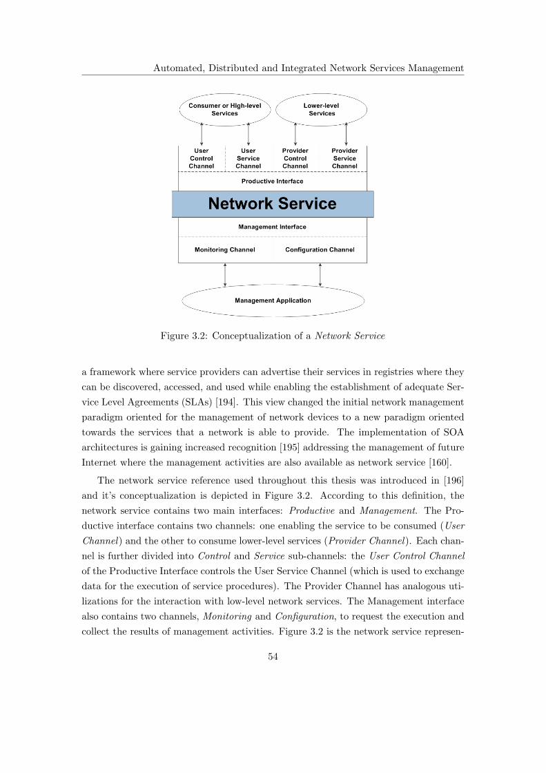
Automated, Distributed and Integrated Network Services Management
Figure 3.2: Conceptualization of a Network Service
a framework where service providers can advertise their services in registries where they
can be discovered, accessed, and used while enabling the establishment of adequate Ser-
vice Level Agreements (SLAs) [194]. This view changed the initial network management
paradigm oriented for the management of network devices to a new paradigm oriented
towards the services that a network is able to provide. The implementation of SOA
architectures is gaining increased recognition [195] addressing the management of future
Internet where the management activities are also available as network service [160].
The network service reference used throughout this thesis was introduced in [196]
and it’s conceptualization is depicted in Figure 3.2. According to this definition, the
network service contains two main interfaces: Productive and Management. The Pro-
ductive interface contains two channels: one enabling the service to be consumed (User
Channel) and the other to consume lower-level services (Provider Channel). Each chan-
nel is further divided into Control and Service sub-channels: the User Control Channel
of the Productive Interface controls the User Service Channel (which is used to exchange
data for the execution of service procedures). The Provider Channel has analogous uti-
lizations for the interaction with low-level network services. The Management interface
also contains two channels, Monitoring and Configuration, to request the execution and
collect the results of management activities. Figure 3.2 is the network service represen-
54

Automated, Distributed and Integrated Network Services Management
tation modeling as a black box which implements a given set of functionalities regardless
of the underlying technological details. A network service becomes completely defined
through its interfaces that implementers and users must comply to. This definition may
contain a set of activities that can be performed individually or collectively, pursuing
the same goal, like the network’s productive services (like DNS, Email, DHCP, etc.),
applications, protocols, mechanisms (such as IP, routing, etc.) or devices. With this
approach, the networked functions, objects, and processes from heterogeneous sources
are exposed as hierarchical services embedding management functionalities, creating a
dependency graph decoupled of the underlying implementation details where the man-
agement functionalities are also represented as network services. An example of such an
hierarchical network service domain is depicted in Figure 3.3.
Figure 3.3 depicts two types of services: one group of services performing produc-
tive operations and a group of services executing the management tasks. A DNS Client
uses the service provided by DNS Service which on the other hand consumes the ser-
vices provided by the DNS Protocol and IP Protocol to exchange messages. From the
management perspective, the service provided by Network Service Management enables
an independent access to the management functionalities by any network management
application. The Network Service Management consumes a group of lower-level manage-
ment services responsible for the management of each productive network service such
as DNS Service Management, DNS Protocol Management and IP Protocol Management.
A clear hierarchy is demonstrated for both service types.
3.5.2 Network Management Activities
Network management activities were introduced in the OSI’s FCAPS classification. Even
though these classifications were presented in the early days of network management,
they are still considered a reference for the operational network management includ-
ing for future Internet management [160]. However, the most recent requirements for
the automation of management activities, new network management activities must be
considered [196].
The operational management activities are represented using traditional FCAPS clas-
sification. It includes the procedures that deal with the functional aspects of network
management such as: fault management involving the detection, recovery and docu-
mentation of anomalies and failures through the examination of alarms, statistics or
reports; configuration management ensuring the network’s desired operation by record-
ing, maintaining and updating network configurations. It involves tasks such as defining
55

Automated, Distributed and Integrated Network Services Management
Figure 3.3: Network services domain including management
threshold values and names, setting filters, configuration changes and corresponding
historic documentation, software installation, etc; accounting management that pro-
vides user management for billing in accordance with network resource usage. Some of
the defined functions include tariff administration, charge generation, bill production,
payment processing, usage reports generation, distribution and surveillance, etc; perfor-
mance management that ensures a reliable and high quality network operation, therefore,
it encompasses all the measures required for ensuring that QoS parameters conforms to
the service level agreement. Some of these relate to resource monitoring for performance
bottlenecks, log evaluation and regulation of crucial performance parameters such as
throughput, delay, packet loss, congestion level, etc; security management refers to the
56

Automated, Distributed and Integrated Network Services Management
management activities related to the network’s security threats while ensuring user pri-
vacy and controlling user access rights. These include the definition of security policies,
threat analysis, user access control enforcement, definition of confidentiality and privacy
schemes, security report generation, etc. It is important to refer that all operational
activities rely on the two most basic network management interfaces: monitoring and
configuration.
Automation of network management procedures require high-level independent man-
agement information representations. One of the most common forms of these represen-
tations are the network management policies which are used to describe the pretended
behavior of the managed services. The definition and implementation of these policies
requires a new group of activities that are not contemplated on the operational net-
work management activities. This new group of management activities are referred to
as strategic management [196] and includes the definition of the global security policies
to be enforced in the management domain (containing the different security solutions
depending in the service offered and who is consuming it), definition of the network
service access policies (for the service consumption), definition of the high-level network
management policies (that embed the business goals) and from which the service behav-
ior is derived. At this level, the global naming and addressing strategies are also defined
for all the managed services. Monitoring information is taken (in the form of technical
reports) regarding the operational management deployment and user satisfaction levels
that might lead to changes in the business-oriented service management policies.
In order to ease the deployment of some of the high-level network management poli-
cies into the corresponding operational activities, a new intermediary group of activi-
ties is introduced. These are referred to as administrative management activities [196],
and are responsible for ensuring that all administrative requisites are met according to
strategic requirements. Some of the activities include the enforcement of naming and
addressing schemes defined in the strategic management, generation of technical docu-
ments to be used as input for the operational and strategic management (like service
consumption and accounting reports), monitoring of the operational network manage-
ment activities and generation of the adequate procedures to guarantee the operational
network management is in accordance with strategic management definitions.
3.5.3 Automation and Distribution
The most common solutions for the automation and distribution of network services
management use independent representations later mapped into heterogeneous man-
57
Automated, Distributed and Integrated Network Services Management
aged element interfaces, be it through a syntactic or semantic management translation,
or both. However, the implementation of management translations is far from ideal,
potentiating content loss or requiring intensive administrator manual intervention due
to the lack of automatic processes that map the semantics inherent to all the heterogene-
ity available in contemporary networks. These limitations are further amplified when
considering the management of large scale domains. There is also a trend that uses
network services provided by SOA architectures to hide the complexity of the network’s
distributed processes. This implies that the management activities also become available
as network services to manage the network’s productive services.
A new mid-level architecture addressing the heterogeneous network service man-
agement, while promoting the automation of some management procedures, is being
proposed. It uses the network service definition presented in the previous section where
all network services include two basic network management interfaces for the monitoring
and configurations tasks. Depicted in Figure 3.4, the new Automated, Distributed and
Integrated Network Service Management framework is composed of two peer subsystems.
One deals with the monitoring tasks (Automated and Distributed Network Service Mon-
itoring (SMON)) and the other with the configuration tasks (Mid-level Network Service
Configuration (MiNSC)). Both subsystems provide two independent services that high-
level network management applications might use to manage the network’s productive
services regardless of their underlying technological details. Both subsystems are able to
cooperate in the augmentation of the network’s productive service resilience to node’s
failures or performance degradation, automatically migrating a service instance. In order
to perform the migration procedure, each subsystem has the following responsibilities:
• The monitoring subsystem (SMON) is responsible for the calculation of the network
service’s QoS levels and comparing them to the pretended values, defined adminis-
tratively, as well as the calculation of the corresponding configuration management
operation which brings the monitored service to the pretended state;
• The configuration subsystem (MiNSC) is responsible for effectively deploying con-
figuration management operations triggered by the monitoring service or high-level
management applications, abstracting the network’s productive services heteroge-
neous implementation details creating a uniform management view.
These are the most important goals aimed by the Automated, Distributed and Integrated
Network Services Management framework:
58

Automated, Distributed and Integrated Network Services Management
Figure 3.4: Automated, Distributed and Integrated Network Services Management
• Present a mid-level service, based on a distributed architecture, for network services
management. Operational management is realized through two basic management
interfaces, monitoring and configuration;
• Automation of some management tasks at the intermediary level, such as the
network service resilience improvement. This simplifies the high-level network
management applications. Simplification of the high-level network management
applications is also obtained by not requiring the implementation of translation
mechanisms to support management heterogeneity.
• Improve the network’s productive services resilience by migrating the instances’s
execution when needed. With the monitoring service measuring the service QoS
levels and automatically triggering reconfiguration procedures (that are able to
spam from a single configuration parameter fine tuning to the complete or partial
service replication procedure) the network service resilience is improved in terms
of instance’s failure or performance degradation.
The SNMP protocol can provide a reliable and secure management data transport be-
tween the framework elements. The implications of using SNMP is studied later in this
thesis. The proposed subsystems are tightly related and their presence is essential to
provide the network services operational management. The next sections present the
two main building blocks of the proposed framework. However, only the configuration
management subsystem is explored in detail in the following chapters, as is the focus of
this thesis.
59

Automated, Distributed and Integrated Network Services Management
Figure 3.5: Automated and Distributed Network Service Monitoring
3.5.4 Automated and Distributed Network Service Monitoring (SMON)
The deployment scenario provided by the Automated and Distributed Network Service
Monitoring subsystem is depicted in Figure 3.5 and published in [197]. The monitoring
process is distributed using a set of monitoring modules. These modules are classified
into Active Monitoring Server (AMS) and Monitoring Server Candidate (MSC), with
AMS actively performing monitoring tasks and MSC in stand-by mode, not actively
performing any type of monitoring task. However, MSC modules are prepared to be-
come AMS when decided by the decision module. The decision module implements the
concept of policy management server that derives management decisions from opera-
tional management policies applied to a set of QoS values calculated by the monitoring
modules.
The distribution of the monitoring modules as well as the decision to make them
AMS or MSC is yet to be studied. However, this process may be achieved with the aid
of human intervention thus, Active Decision (AD) modules must support an interface
to an administrator or higher-level management servers like generic Lightweight Policy
Management Servers (LPMSs). The AMS modules are mid-level management servers
acting simultaneously as managers and agents. This creates a hierarchical monitoring
60

Automated, Distributed and Integrated Network Services Management
system with several functional management levels, each one with filtering and processing
capabilities of the monitored data. This mechanism provides scalability, maintaining
the higher flows of management data contained on the leaves of the monitoring service
hierarchy. On the other hand, in higher-level monitoring modules, closer to the top of
the functional hierarchy, that is, close to the AD modules, subsystem reliability and
resilience will be much more important than performance. This can be attained by
carefully calculating AMSs and MSCs quantities and location.
3.5.5 Mid-Level Network Service Configuration Management (MiNSC)
This thesis focus on the Automated, Distributed and Integrated Network Service Man-
agement framework’s second component: the Mid-level Network Service Configuration
subsystem. It has the responsibility of deploying configurations simplifying manage-
ment of heterogeneous network services. This subsystem is extensively explained and
evaluated in the following chapters.
3.6 Conclusion
Currently, there is a tendency to use high-level network management representations to
describe the goals pretended for a management domain. Those high-level representa-
tions are later translated into each management interface of the elements being managed
through a translation mechanism using two different strategies. They either implement
a syntactical or semantical translation. However, the implementation of management
translation mechanisms incurs in well identified limitations that include content loss and
extensive administrator intervention dependency, which, for large scale heterogeneous
environments may be unfeasible. With the adoption of a SOA architecture the prob-
lem remains and solutions that deal with heterogeneous network service management
are required. With this in mind, an Automated, Distributed and Integrated Network
Service Management framework is proposed. This solution not only supports manage-
ment of heterogeneous network services, simplifying NMS, but also provides additional
functionalities improving service resilience.
61

62
Chapter 4
MiNSC: Mid-level Network
Services Configuration
Management
This chapter describes the Mid-level Network Service Configuration (MiNSC) subsystem
introduced in previous chapter. It summarizes the motivations leading to the develop-
ment of this new configuration management framework. The MiNSC’s architectural
details and its functional model are also explained. This chapter ends with usage con-
siderations for MiNSC based solutions, including its inherent limitations.
4.1 Motivation
Heterogeneous network management problem is far from being solved and networks are
evolving towards a service oriented paradigm which needs a network management evo-
lution. The implementation of high-level network management applications, aiming to
simplify and automate management procedures, make use of syntactic and semantic
translations to enforce high-level management representation into the low-level network
element’s management interface and data model. Regardless of whatever management
translation alternative is used, it incurs into important limitations such as management
data loss or inconsistencies, as well as dependency on manual intervention by the ad-
ministrator. Furthermore, when speaking of larger scale management domains, these
strategies are complex to implement. It is also important to notice recent trends to-
wards the implementation of service oriented architectures. This hides the networks
complex implementation details using an abstracted view of the network and it’s com-
63

MiNSC: Mid-level Network Services Configuration Management
ponents, enabling the establishment of adequate SLA that users and service providers
must comply to. These conclusions motivate the development of the MiNSC framework,
a configuration management service, based on standard technologies, that overcomes the
implementation of management translation mechanisms while promoting management
simplification.
4.2 Integrated Network Service Management
Network services tend to be well described in international standards, management in-
formation models can be derived from those descriptions and all network service imple-
mentations, in agreement with the standards, should be manageable using only standard
technologies (information and data models), creating a network service management ab-
straction. The implementation of such standard-based management abstraction unifies
the network service management regardless of the underlying implementation details.
This is the basis for the MiNSC’s proposal and represents MiNSC’s alternative for het-
erogeneous network service management which is divided into two sub-layers. The first
(and lower) management abstraction layer unifies the management of specific network
services through the implementation of standard-based service management information
models (referred to as instance management information model) on a standard inter-
face. The second (and higher) management abstraction layer, takes advantage of the
unification provided by the lower layer to enable an additional and independent set of
meta-configurations defining the overall service behavior which promotes automation of
the service management. Those meta-configurations are defined by the service manage-
ment information model and are directly used in the automatic service configuration
deployment (service instance configuration generation) and automated service instance
execution migration, which improves the managed service’s resilience and scalability.
On the top of MiNSC, high-level network management applications use its management
abstraction for simplification.
The MiNSC’s two layer management model is depicted in Figure 4.1, which is an
evolution of the previous proposal presented in Figure 3.1. As stated previously, the
Configuration Management Data represents the high-level (business oriented) policies
while the Network-Wide Configuration Data represents the mid-level, independent net-
work service meta-configurations following the service management information model.
Such configurations result from the combination of the business-oriented management
policies and the performance of the managed service. The MiNSC framework is re-
sponsible for the automatic deployment of the network service configuration, based on
64

MiNSC: Mid-level Network Services Configuration Management
Figure 4.1: MiNSC’s network service management model
the meta-configurations defined, calculating the quantity of network service instances re-
quired and automatically deriving an independent configuration for each one. In order to
execute the service configuration deployment, MiNSC’s higher management abstraction
layer uses the instance management information model as well as the instance’s topo-
logical information, concerning the management domain, in order to acknowledge their
availability. This layer also requires the monitoring information to initiate some man-
agement procedures, namely to execute the automatic migration of the service instance
execution and service physical expansion process. MiNSC’s objectives are summarized
as follows:
• As mentioned in the previous section, the current trend on management of network
heterogeneity is through the implementation of intermediary translation mecha-
nisms either through a syntactical or semantic approach. MiNSC overcomes the
need for intermediary network management translations by using standard-based
service management information models, to abstract the heterogeneous manage-
ment representations, associated with a standard network management interface
able to effectively support configuration management operations. This ensures
management applications interoperability, eliminating the need for translations.
65
MiNSC: Mid-level Network Services Configuration Management
Thus, MiNSC creates a new service configuration management interface unify-
ing network service management. Network service vendors are then responsible
for supporting the proposed interface, developing its instrumentation, in order to
adequately manage their heterogeneous implementations;
• Automation of management procedures is one of the most important goals pursued
by contemporary network management proposals. In this sense, MiNSC takes
advantage of the management abstraction implemented in two layers to provide
some automation, namely for the service configuration deployment and instance
execution migration, which improves the service’s resilience and scalability;
• Provide a scalable and resilient architecture to address scale requirements of con-
temporary and future networks by using a distributed management framework over
both abstraction layers. As such, scalability and resilience improvement methods
for both network and management services can be futher achieved through repli-
cations of the service instance’s independent configurations, enabling a migration
of the service execution.
4.3 Architecture
MiNSC is part of the Automated, Distributed and Integrated Network Services Man-
agement framework responsible for the enforcement of configuration management oper-
ations. It’s logical deployment scenario is depicted in Figure 4.2 and most of its details
can be found in the following papers [44, 45]. It is clearly similar to the SMON sub-
system and they may even share the same physical infrastructure. MiNSC relies on a
two layered architecture (one layer for each abstraction level) composed by a distributed
group of configuration servers and managed service instances. Figure 4.3 provides details
regarding MiNSC’s layered architecture which is explored thoroughly in the following
sections.
4.3.1 Network Service Instance Management Layer
Following a bottom-up approach, the first management layer is composed by service in-
stances executing the network’s productive services (such as DNS, Dynamic Host Config-
uration Protocol (DHCP), etc.). The execution of a service instance can be classified as
active (when actively executing a network service) or candidate (not actively executing
a network service but in stand-by mode ready to execute a service in the future). There-
fore, a network service instance may be classified as an Active Service Instance (ASI) or
66

MiNSC: Mid-level Network Services Configuration Management
Figure 4.2: MiNSC’s deployment scenario
Candidate Service Instance (CSI), depending on the execution state, and a network node
may possess several classifications (one for each type of service). Active and candidate
instance classification (or state) is temporary, depending on the configurations assigned.
However, special attention is required when assigning their classification. Candidate
instances should be placed in distinct administrative domains, use different operating
systems or software implementations/versions to avoid active instance’ security vulnera-
bilities, be connected using different Internet Service Providers (ISPs), etc. This makes
active and candidate instance the most heterogeneous possible, reducing their probabil-
ity of simultaneous failures, consequently improving resilience. It is also important to
note that for a instance to be classified as candidate no configurations are required, the
absence of configurations places the instance execution in stand-by.
The process of defining the service instance classification depends on the adminis-
trative requirements as well as the number of service instances available. Two distinct
instance classification alternatives can be used:
• The administrator provides a graduated list of service instances available. Based
on the service redundancy redistribution defined (service meta-configurations) the
number of active and candidate instances is calculated. The list provided is used
to assign classifications;
67

MiNSC: Mid-level Network Services Configuration Management
Figure 4.3: MiNSC’ service management architecture
• Implementation of a serialization algorithm that by taking the number of service
instances available, the service redundancy distribution defined in addition to the
costs associated to each service instance, applies a cost minimization algorithm to
find the best network service deployment pattern and corresponding ASI and CSI
classification.
Regardless of the alternative implemented, it solely provides an initial service deployment
pattern. However, this process represents a very important mechanism as it directly im-
pacts the MiNSC’s capability of improving the network service resilience and scalability.
Then MiNSC may modify the service instance classification according to the monitoring
68
MiNSC: Mid-level Network Services Configuration Management
information, reflecting the instance’s performance and fulfillment to the administrative
goals. Dynamically varying the service instance classification/state (according to the
monitoring information) enables service execution tuning beyond the traditional network
service configuration parameters, providing additional management flexibility. The main
advantages are:
• In case of a faulty service instance, service execution can be transferred to a dif-
ferent instance maintaining the service’s intended performance. This is achieved
by automatically replicating the ASI configurations to a CSI (changing it’s clas-
sification to ASI), thus transferring execution from the faulty ASI. The decision
to perform the migration operation is taken by the administrator (through the in-
spection of monitoring data) or by an automated monitoring system (like SMON),
acknowledging the need to perform a migration procedure based on the values of
QoS obtained. This mechanism improves resilience to service instance failures or
performance degradation;
• MiNSC’s capability to dynamically add new service instances acting over their
classification improves network service scalability. Once a scalability problem is
detected within a network service, SMON triggers a network service expansion
procedure to increment the number of ASI instances, reducing the number of CSI
instances available. A similar procedure can be implemented to reduce the amount
of ASI instances used, thus enabling an efficient allocation of network resources;
• Economical advantages are also inherent to MiNSC’s dynamic classification man-
agement. Performing a more efficient resource management and resilience improve-
ment methods promotes the maintenance of established SLA.
At this level, the first management abstraction is implemented, providing a unification
layer over the service implementation’s specificities. This means that, for a given service
(let’s say service A) all the heterogeneous implementations (A.1, A.2, A.3, etc) are
equally managed based on a unique instance management information model for service
A. All management tasks are deployed through a standard network management interface
(MIB) implemented by the configuration management agent present in all network nodes.
This agent, besides implementing the management interface, also manages the node’s
service instance classification and supports the creation of their instrumentation. The use
of standard-based service management information models implemented on a standard
service management interface overcomes the need for network management translations,
which is one of the MiNSC’s primary goals. It is important to notice that all service
69

MiNSC: Mid-level Network Services Configuration Management
instance configurations at this level are calculated at the Service Management layer.
The creation of a new configuration management interface unifying management, makes
all service implementers responsible for the creation of the adequate instrumentation for
management of their products, avoiding disclosure of implementation details.
4.3.2 Service Management Layer
Based on the service management information model, the MiNSC’s higher management
abstraction layer defines service management meta-configurations embedding the behav-
ior desired for the network service. These meta-configurations are used, among others, to
automatically generate each network service instance configuration at Network Service
Instance Management layer. The following objectives are pretended for this layer:
• Implement a distributed architecture supporting high levels of scalability and re-
silience for the configuration management service;
• Use the configuration independence, provided by the Network Service Instance
Management layer, to support automated service management procedures like the
automatic generation of service instance configuration, service instance migration
and service expansion/redution (automatic addition or removal of network service
instances);
• Use of a standard network management interface that, besides enabling the man-
agement of the network service meta-configurations (defined by the service man-
agement information model), promotes the interoperability of higher-level network
management applications;
• Support for a standard interface to be used with the monitoring subsystem. This
monitoring subsystem should be able to detect functional or scalability problems
at both layers and trigger the realization of configuration management operations
at this layer;
• Enable the implementation of a service instance serialization algorithm to deter-
mine the classification of service instances according to administrative management
goals.
70

MiNSC: Mid-level Network Services Configuration Management
Figure 4.3 depicts the elements presents at the Service Management layer. Much as
the Network Service Instance Management layer, the configuration management servers
support simultaneous management instances with classifications such as Active Config-
uration Server (ACS) or Candidate Configuration Server (CCS). The interface with the
monitoring system is represented by a connection with the SMON server. The ACS
classification refers to servers actively managing a network service. They maintain the
network service meta-configurations in addition to a graduated list of the service in-
stances used for service deployment. On the other hand, the CCS classification refers to
a management server that is in a stand-by mode to be used in case of an ACS failure
or service expansion. Figure 4.3 represents two logical groups of configuration manage-
ment servers for the management of two network services. The Service Management
layer also includes the Configuration Pointing Server (CPS), which plays a fundamen-
tal role within the layered architecture to enable a scalable and resilient management
operation, by aggregating the configuration servers classification.
An MIB is implemented by the Service Management layer elements to promote
higher-level management application interoperability. This same type of interface is
used for interaction with the monitoring system, providing software independence, used
to inform the management servers as to the need to deploy a configuration management
procedure. CPS servers use the monitoring interface to manage the classification of
management servers thus migrating and extending servers to improve the management
framework’s overall scalability and resilience. It is important to note that, at this layer,
the network service management procedures are divided into server’s associations. Here,
ACS and CCS servers are grouped and perform management tasks for a given network
service. Their task is complemented by the CPS servers which are shared by the manage-
ment domain to identify, at any given time, ACS servers responsible for the management
of a given network service. As network management is a fundamental part of commu-
nication network’s operations, it is very important to ensure its availability even when
in the presence of management server failures. In this sense, and in order to improve
the management framework’s resilience to server failures, the following considerations
should be taken:
• The CPS servers define the ACS and CCS servers classification to perform man-
agement tasks for each network service. They also define the periodicity by which
ACS server configurations are replicated to CCS. This ensures that network ser-
vice management execution is quickly migrated to a different server in the event
of ACS failures (by promoting a CCS server to ACS);
71

MiNSC: Mid-level Network Services Configuration Management
• In case of an ACS failure, detected by the monitoring system, the CPS is respon-
sible for the election of a CCS (using a graduated list of servers) to continue the
configuration management task (replacing the faulty ACS);
• Failures at the CCS servers should not lead to any resilience problem because they
are not actively performing any service management procedure;
• The CPS servers do not introduce resilience constrains within the Service Man-
agement layer. Their database is shared among all of the domain’s CPS servers.
This means that, as long as there are CPS servers available within the domain,
management servers are still able to be assisted.
The Service Management layer also takes into consideration scalability concerns, as it
also relies on the monitoring information to act accordingly. In this sense, in order to
improve the management framework’s scalability, the following considerations should be
taken:
• When the monitoring system informs the CPS as to the existence of performance
degradation due to scalability problems, a service expansion procedure should be
executed to distribute the load;
• A CPS server deactivates part of a faulty ACS configuration, activating the same
part on a CCS using the configurations previously replicated;
• This increases the number of management servers available thus improving the
management service scalability.
Server Referencing
The CPS servers perform an important task within the Service Management layer. Due
to the dynamism of management servers, the CPS servers maintain updated information
regarding which network service is being managed by which ACS servers, while making
this information available to external management applications. The CPS server main
tasks are summarized in the following items:
• As referred previously, the main objective of the CPS is to register and maintain
configuration management servers classification information. This information is
made available to external management applications through a standard manage-
ment interface enabling a simple and fast way to find which servers are responsible
for the management of a given network service;
72
MiNSC: Mid-level Network Services Configuration Management
• The CPS also assists the Service Management layer initial classification of man-
agement servers. This is performed using the implementation of a serialization
algorithm such as the one used for the classification of network service instances.
This should take into account the desired redundancy distribution level for the
configuration management service, the number of management servers available as
well as their location;
• The registration database is shared by all CPS servers available at the management
domain. This ensures information availability while eliminating the single point of
failure and improves scalability;
• The CPS servers are also responsible for setting the configuration replication mech-
anism on the CCS, used to automatically and periodically replicate the ACS server
configurations. These configurations are used for execution migration in case of
failures;
• The configurations replicated in CCS are also used by the CPS servers to deploy
a load-balancing mechanism, increasing the number of ACS servers performing a
network service management, when required.
4.3.3 Configuration Agent
The configuration agents are present in all framework elements, therefore, they play a
fundamental role within the architecture. Their responsibilities include the following:
• Implementation of a standard network management interface, MIB, that ensures a
uniform data representation and management at any layer, thus, promoting inter-
operability. This interface in conjunction with standard-based service management
information models unifies the management of heterogeneous implementations of
network services;
• The management interface implemented support the service instances configura-
tions management, including their classification and replication mechanism;
• Support the development of management interface instrumentation for heteroge-
neous service implementations. Such instrumentation must be developed by the
implementation vendors to avoid disclosure of the service’s implementation details
and improve management efficiency;
73

MiNSC: Mid-level Network Services Configuration Management
• Present the lowest footprint possible into the network node performance. In order
for this to be performed, the agent should be kept simple and efficient.
4.3.4 Configuration Management Protocol
The specification of a configuration management protocol is vital to the efficient en-
forcement of the MiNSC’s management operations to the configuration agents. The
requirements for an efficient configuration management protocol have been studied for
a long time [11, 42]. However, given MiNSC’s management specificities (namely for a
standard configuration management interface, efficient and secure protocol operation)
the previous requirements were redefined [44] to effectively deploy MiNSC’s configuration
management operations. The following list summarizes the most important requirements
for the use of a configuration management protocol within the MiNSC’s framework:
• It must support a standard configuration management interface. Given the mid-
level purpose of MiNSC’s architecture, a standard configuration management in-
terface would promote high-level management applications’ interoperability and
wide use of the MiNSC framework;
• The configuration management protocol must provide an efficient (with the small-
est impact possible for the networks operation), secure (providing user access con-
trol, authentication and message encryption) and reliable operation (error free and
message delivery assurance);
• Management data may have a large volume at times. In this case, the configuration
management protocol must provide an efficient method to transport management
data by using, for example, data compression mechanisms;
• A basic set of configuration management operations must be supported such asGet,
Set, Delete, Modify and Notification which will serve as a basis for the development
of advanced operations such as Backup, Restore and Replicate;
• The management interface must provide a data model definition language with a
balanced compromise between its expressiveness and flexibility, enabling the strict
representation of data models that ensures management applications interoperabil-
ity.
74
MiNSC: Mid-level Network Services Configuration Management
Even though there exist several configuration management protocols that are able to ac-
commodate the previous requirements, some were developed (or are commonly applied)
in network management contexts such as SNMP, NETCONF or HTTP-based transport
protocols. SNMP is the most popular network management protocol mainly due to its
simplicity in terms of use and implementation as well as the interoperability provided
through a well known management interface. It is used mainly for monitoring applica-
tions due to its initial security limitations. This historically deviated the SNMP’s usage
from configuration management operations. The MIB implementers also fail to develop
useful objects for configuration management [11] relying on proprietary implementations
to ensure the device configuration management. The NETCONF protocol was developed
to address the configuration management limitations of SNMP. It possesses a group of
advanced functionalities developed especially for the configuration management of IP
devices. However, due to the fact that it is a recent protocol, it is not as widely used
as SNMP. Finally, HTTP is a generic application data transport protocol that can also
be used for network management operations. HTTP has the advantage of possessing
several development tools and of being a highly flexible protocol due to the use of XML-
related languages. On the other hand, it is not widely used within network management
contexts and its extreme flexibility may impose interoperability problems which can be
a detrimental factor [28]. Taking into consideration the identified set of requirements
for configuration management operations, their deployment as MiNSC’s configuration
management protocol was evaluated, and the results are depicted in Table 4.1.
SNMP
The second and third versions of the SNMP protocol are no longer insecure and unreliable
network management protocols, implementing a USM [198] and VACM [199] security
models. The security model defined in USM is responsible for the algorithms that en-
sure user authentication and message encryption/decryption mechanisms. Secrets keys
are shared by managers and agents for authentication and encryption. For example, the
HMAC-MD5 and HMAC-SHA algorithms are available for authentication and CBC-DES
algorithm for message encryption. VACM is responsible for the administration of the
access rights to MIB objects. This restriction is performed in two dimensions: providing
access to selected parts of the MIB or restriction to specific operations. The reliability
of SNMP’s data transport operations depends on the transport protocol used: the User
Datagram Protocol (UDP) or TCP [200], depending on the management requirements.
75

MiNSC: Mid-level Network Services Configuration Management
Table 4.1: Configuration management protocols evaluation
Features SNMP NETCONF HTTP
Authentication 3 3 3
Access Control 3 3 7
Confidentiality 3 3 3
Reliability 3 3 3
Data Compression Optimization 7 7 3
Scalability 7 3 3
Basic Operations 3 3 3
Advanced Operations 7 3 7
Interoperability 3 3 7
Data Model Definition Language 3 3 7
Data Model Definition Expressiveness 7 3 7
Processing Requirements 3 7 7
Available Implementations 3 7 3
Wide Usage 7 7 7
Scalability is one of the INMF’s most referred limitations. When considering the
traditional use of SNMP, having a central manager station performing monitoring tasks,
periodically polling management agents, a large amount of agents (or when the number of
objects to be pooled is very large) makes the polling period too large and in this situation,
important monitoring information may be lost [11]. This scalability limitation is inherent
to the manner in which SNMP is used regardless of the transport protocol. SNMP
further amplifies this limitation (when using UDP data transport protocol) by requiring
a larger amount of transactions between manager and agents to deploy management
data. Other network management protocols (such as NETCONF) enable the realization
of several management procedures in a single transaction. SNMP used in a distributed
configuration management context, where there is no need for periodic pooling, makes
it a valid alternative.
From the perspective of configuration management operations, SNMP only provides
basic functionalities such as Get, Set, Get-Bulk and Notification, missing several ad-
vanced configuration management operations including support to rollback on configu-
rations as well as configuration history representation. It is important to note SNMP’s
Get-Bulk operation. This operation enables the manager application to retrieve a large
76

MiNSC: Mid-level Network Services Configuration Management
portion of the agent’s MIB with a single request. However, SNMP’s Basic Encoding
Rules (BER) are not space efficient (presenting an high degree of redundancy in the
payload), allied with the non-use of data compression techniques, makes SNMP less
efficient for large data transfers (even though a draft exists [201] for SNMP’s payload
compression).
MIBs represent an important element for the promotion of management application
interoperability. It is a self-contained, well described and well identified hierarchical
structure of management objects which are easily accessible through SNMP. When
speaking in terms of the definition of data models, the SMI is extensively refereed as
being highly limited in its expressiveness because it misses a lot of object-oriented pro-
gramming concepts and rules [153]. However, such a constrained set of management data
definition rules makes the MIB a highly interpretable interface reducing management ap-
plication interoperability issues. From MiNSC’s early information model implementation
perspective, since they are initially constituted by a small group of classes containing
solely attributes (and not methods), associated trough a UML Composition relation,
SMI language representation based on tables and table pointers is sufficient. Besides,
SNMP is a very mature technology, with several tools available for the development
of SNMP-based management solutions, also including the development, validation and
implementation of MIBs.
NETCONF
NETCONF is an ambitious project which tries to solve some of the most relevant SNMP’s
configuration management limitations. The IETF’s NETCONF protocol provides an ad-
vanced set of features which accommodate the configuration management requirements
of current and future networks. It is a recent proposal whose standardization occurred
in September of 2006 [27] and it’s data model definition language occurred in October
of 2010 [28]. NETCONF provides a reliable and secure provisioning of configuration
management operations which can be elaborated using the following data transport
protocols: SSH, TLS, BEEP and SOAP. However, NETCONF is not confined to the
previously mentioned data transport protocols and many others may be used as long
as they are connection-oriented, providing a reliable and sequenced data delivery, and
include support for authentication, message integrity and confidentiality. Access Con-
trol was not addressed in NETCONF’s initial specification. However, a recent proposal
already addresses the issues associated with NETCONF’s lack of access control (NET-
CONF Access Control Model (NACM) [202]) by creating a standard mechanism which
77

MiNSC: Mid-level Network Services Configuration Management
will restrict operations and contents for each authorized user. NETCONF implements
a document oriented configuration management approach with data being encoded in
XML. XML’s excessive verbosity represents a considerable limitation for a NETCONF
operation incurring into high overhead in the communication when a small number of
objects is being managed. The initial specification does not address data compression
mechanisms even though some work is done to address this problem [203,204].
NETCONF is still a recent configuration management protocol and extensive eval-
uation is required to access its capabilities. It is based on the client-server paradigm
but improved scalability is obtained by requiring a single client-server transaction to
deploy a large number of management operations. Such capability is frequently com-
pared to SNMP over UDP which requires a larger number of transactions specially
when managing a large number objects [205]. However, the XML data encoding, pro-
cessing and manipulation is not trivial and when it is performed at managed elements
containing limited resources, some performance limitations may be introduced. This is
further enhanced with the use of compression and encryption algorithms that incur in
further processing requirements, so it is important to maximize the efficiency of auxiliary
tools, like XML processors and encryption tools [206]. NETCONF defines, just as does
SNMP, a management interface called datastore. This datastore works as a database
by storing the managed element’s XML configuration (including the state information).
The datastore structure is defined by the NETCONF’s data model definition language,
YANG, which provides a standard way to define NETCONF’s management data mod-
els. The specification of a standard management interface (including the standard data
model definition language) and a standard configuration management protocol ensures
the NETCONF based management applications interoperability.
Considering the configuration management operations provided by NETCONF, only
the basic set of operations are available by default. However, an advanced set of op-
erations may be provided as Capabilities to complement the basic operations, resulting
from the capabilities negotiated between the manager and the agent. This maximizes
the operational capabilities of both ends. The basic operations defined for the man-
agement of configurations defined in datastores include: get, to retrieve the managed
element running configuration and state information; get-config, to retrieve a specific
part of a datastore configuration; edit-config, to modify all or a specific part of a data-
store configuration; copy-config, to create or replace a datastore configuration with the
contents or another datastore; delete-config, to delete configurations belonging to a spe-
cific datastore; lock, to lock a datastore configuration for concurrency purposes; unlock,
to release a previous lock. The advanced operations include, among others, the following
78
MiNSC: Mid-level Network Services Configuration Management
capabilities: writable-running capability, to refer to the capability of the agent to write
on the running configuration datastore; candidate configuration capability, to refer to
the agent’s support for candidate datastore; confirmed commit capability, to request the
response, in a given time period, as to the execution of a configuration management
operation. In case of timeout the manager and agent configurations revert to the previ-
ous sate; rollback on error capability, to refer to the capability of the agent to rollback
to a previous stable state; validate capability, to refer to the capability that performs
content verification in a datastore; distinct startup capability, to refer to the capability
that defines a managed element startup configuration datastore.
NETCONF standards were defined during the last years including its data modeling
language. Initial experimental implementations are being developed and tested. A long
path is expected for NETCONF when it comes to wide usage. However, it provides the
means to cope with today’s configuration management requirements while having space
to evolve and reach for new functionalities.
HTTP
HTTP [207] is an important data transport protocol for general use being very popular
for the retrieval of web pages. Due to its vast popularity, it has a wide community
of developers with several tools and APIs supporting the development of HTTP-based
solutions. HTTP provides a generic and simple data transport operation supporting
several types of payload data through a reliable and secure data transport operation
using TCP and TLS [208, 209]. For data compression HTTP specification [207] has
defined GZIP [210], Compress, Deflate [211] and Identity even though others could be
used. It has implemented a basic access control mechanism based on user authentication.
The two standard user authentication methods available for HTTP are found in [212]
and include:
• The most conventional form of authentication is the Basic Authentication, where
the user sends its authentication credentials within a base64 encoded string to the
server which can easily be intercepted and decoded. This authentication method
is not considered a secure procedure;
• The HTTP’s Digest Authentication employs increasingly sophisticated security
mechanisms based on hashes to ensure the users’s authentication. This scheme
does not encrypt the message, rather it creates an authentication method which
avoids sending the user’s credentials in clear. When a client requests a resource
79

MiNSC: Mid-level Network Services Configuration Management
using a Digest Authentication, the server replies with a nonce (a unique server-
specified data string), then the client executes an MD5 hash of the username,
password, the URI of the desired resource and the nonce sending it back to the
server. The server verifies the hash sent with its own calculation of the same
elements and in the case of a match, the user authentication is performed.
In order to identify the resources present on the server HTTP defines URIs. Allied to this
identification is a group of methods which provides a basic set of actions to be performed
on server resources. Some of those methods defined by the HTTP specification include:
• Get method that is issued by the client to obtain a server’s resource representation;
• Post method that is issued by the client to send an entity containing arbitrary data
to the server for processing. The URI sent in the message identifies the processing
application;
• Put method that is issued by the client to command the server to store a resource
representation on the URI sent in the message. For security reasons, the use of
this method may be prohibited;
• Delete method enables the client to erase a resource representation (identified by
an URI) present on the server. However, just as the Put method, it is subject to
security restrictions.
From the network management perspective, this set of methods provides the basic set
of functionalities required with the exception for the support of notifications. HTTP
implements a client-server architecture with one manager station managing several net-
work elements. Due to the fact that HTTP is a generic data transport protocol, it does
not contain a self-contained management interface and data model definition language.
However, since HTTP is commonly used to transport XML data, the XSD document
definition language can be used to define management data models. According to [28],
the use of such a generic language for a data model definition may introduce interoper-
ability limitations due to the language’s extreme flexibility, enabling multiple forms of
model definition. In order to be applied in the context of network management, tight
data model definition languages are preferred because they reduce the definition ambi-
guities that may result. The use of XML also contains advantages when representing
management data based on complex data models. Using XML over HTTP protocol pro-
vides a document-oriented management approach by using a single transaction between
80

MiNSC: Mid-level Network Services Configuration Management
manager and agent to perform several management operations over a large set of man-
agement objects. This improves scalability, however it is also important to ensure that
the XML processing tools present at agents perform efficiently when manipulating large
files to avoid performance degradation. The HTTP protocol gained visibility in network
management for its flexibility, carrying management data encoded in XML, which can
be easily visualized in any traditional web-browser. However it never gain wide usage as
other network management protocols.
Configuration Management Protocol Evaluation
Table 4.1 depicts the evaluation of the previous configuration management protocols
according to a group of functionalities considered relevant for the provisioning of con-
figuration management operations in MiNSC framework. Table 4.1 indicates a clear
difference between the HTTP protocol and the other two in terms of the management
functionalities provided. Such differences demonstrate HTTP’s inability to be used in
MiNSC’s architecture since it does not provide important functionalities that would be
decisive for its usage. The HTTP’s main limitations are inherent to the protocol’s generic
purpose which, when associated to a general purpose data model definition language,
may incur in interoperability’s limitations in the context of configuration management.
The HTTP protocol is not widely used for management tasks, which represents an im-
portant factor as an easy integration with existing management solutions is an important
requirement. In addition to this, the HTTP protocol does not provide an advanced group
of configuration management operations, being limited to a group of methods built to
enable an efficient operation in the web environment lacking, for example, the notifica-
tion definition. Besides, HTTP lacks a well defined and self-contained interface for the
managed resources description and identification (such as a MIB).
SNMP and NETCONF represent the strongest candidates that can be used within
MiNSC’s distributed framework. Regardless of their considerable differences (SNMP has
been historically used for monitoring purposes while NETCONF was born from INMF’s
configuration management limitations), they present important similarities considering
their usage in MiNSC’s framework:
• Both protocols provide a reliable and secure configuration management operation
with authentication, confidentiality and access control. Even though the access
control is not part of NETCONF’s initial specification, a draft has been proposed;
81
MiNSC: Mid-level Network Services Configuration Management
• Both protocols promote management application interoperability through the im-
plementations of standard languages to define the management interfaces. How-
ever, NETCONF’s data model definition language (YANG) was standardized re-
cently and extensive study, development, implementation and deployment is yet
to occur before it reaches the INMF’s SMI maturity. For this reason, the imple-
mentation of NETCONF might still incur into some interoperability limitations;
• A considerable amount of implementations and development tools are available
for both protocols. However, due to the fact that NETCONF is still a recent
protocol, many of the implementations available are still being developed. On
the other hand, SNMP provides a stable set of implementations and APIs for the
development of SNMP-based applications with a large number of tools, including
for the specification and validation of MIBs;
• The basic set of configuration management operations is provided by both protocols
enabling the retrieval, update and deletion of managed object’s values as well as
notification support;
• Both protocols are still not widely used for configuration management operations.
SNMP is mostly applied for monitoring tasks and NETCONF has not gained wide
acceptance yet. However, the use of the SNMP protocol for configuration tasks
involves a small effort since the protocol has defined methods to change the object’s
state by requiring only the provisioning of configuration management objects in
the MIBs.
On the other hand, some relevant differences must also be considered:
• SNMP lacks the advanced set of configuration management operations provided by
NETCONF that includes the locking of configurations (for concurrency support),
rollback on errors, configurations with time validation, negotiation of features with
agent capabilities, configuration validation, atomic configuration operations, his-
tory, among others;
• The design simplicity of SNMP makes it much simpler to implement (at the agent
level) and use by pushing the management complexity towards the management
application. In this sense, lightweight agents are the only requirements. On the
other hand, NETCONF requires advanced (and intelligent) agents with increased
82

MiNSC: Mid-level Network Services Configuration Management
resource consumption. NETCONF agent design and implementation must be care-
fully performed due to the fact that processing large XML files may reduce per-
formance;
• SNMP is a widely used network management protocol while NETCONF is taking
the first steps in the network management world. Thus, in the perspective of
enabling integration with contemporary network management applications the use
of SNMP has considerable advantages: the same protocol and agents are used
requiring only support for the proposed standard-based models. Furthermore,
NETCONF is not used for monitoring management, so a management domain
would have to use different technologies for monitoring and configuration;
• SNMP and NETCONF performance has been studied in several works [146, 205].
Their main conclusion refers to an enhanced performance of NETCONF when the
number of managed objects is considerably large. When the number of objects is
lower, NETCONF’s excessive overhead (due to XML data coding) leads to per-
formance degradation. In opposition, SNMP provides an improved performance
when the number of managed objects is lower due to its low overhead. With an in-
creased number of managed objects, SNMP requires a higher number of transaction
which may result in a scalability issue. However, this analysis takes into account
the usage of SNMP over UDP protocol which should not be directly compared to
NETCONF’s usage of the TCP protocol;
• NETCONF’s data model definition language supports a higher degree of expres-
siveness enabling the application of object-based oriented concepts such as inher-
itance or hierarchy. This enables the representation of much more complex data
models than INMF’s SMI.
Considering the evaluation of both protocols, the author decided to use SNMP as
MiNSC’s configuration management protocol due to the following reasons:
• SNMP seems to be the best alternative to promote a smooth integration with
contemporary network management applications. The success of NETCONF is
still unknown. There is no way to predict if it is ever going to be widely used
or not. On the other hand, SNMP is already widely deployed and if it is used in
MiNSC, it will facilitate integration with existing management solutions;
83

MiNSC: Mid-level Network Services Configuration Management
• MiNSC is independent regarding the configuration management protocol used. It
merely uses the protocol to provide a reliable and secure channel for the provi-
sioning of the framework’s element configurations. The protocol implemented can
change in time, along with the configuration management requirements;
• Future transition from the use of SNMP to NETCONF is possible and simple.
In the case of more complex management data models or requirements for more
advanced configuration management functionalities, it is easier to migrate from
SNMP to NETCONF than the other way around;
• MIBs and SMI provide a well known and mature technology with a lot of devel-
opment and validation tools. Those tools are extensively experimented and tested
providing a smooth path for implementation of a real prototype;
• Most of INMF’s scalability evaluations use its traditional implementation through
a centralized architecture which results in a low scalable operation. When used
in a distributed management architecture INMF’s (potential) scalability limita-
tions should be mitigated. In MiNSC, the configuration management process is
distributed by a group of ACS servers. Besides, the use of the TCP transport
protocol adds the capability to send in a single transaction an unlimited amount
of Get/Set operations, addressing the scalability issues for the management of a
large number of objects. From an empirical point of view, even though a net-
work element may contain a large number of managed objects, not all objects are
managed at the same time, or all the time;
• In order to maintain management application simple (within a management do-
main), and since SNMP is already widely used for monitoring a SNMP-based
configuration management solution must be pursued to avoid duplication of tech-
nologies.
SNMP and NETCONF provide valid alternatives for MiNSC’s overall configuration man-
agement technology. According to the previous analysis, SNMP seems to have advantage
at this moment so it was the one selected, however thanks to MiNSC’s independence
(from the configuration management protocol), the use of SNMP is not definitive and
can naturally evolve towards the use of a more advanced solution, such as NETCONF.
84

MiNSC: Mid-level Network Services Configuration Management
4.3.5 Security
The security of distributed systems assumes a greater importance with direct repercus-
sions on their performance, reliability, availability and others. From a distributed system
perspective, security must be provided by two main parts [213], one that deals with the
security of the communication between remote processes (or users), using a secure chan-
nel that ensures authentication, message integrity and confidentiality. The other part
deals with the management of authorization, ensuring that a process (or user) is only
granted access rights to perform the operations that it is entitled to.
The implementation of a secure channel, between remote processes, is required in
order to avoid the most common forms of security threats such as unauthorized access to
data (solved through confidentiality), unauthorized modification of data (solved through
the implementation of mechanisms that ensure message integrity) and unauthorized
activities (solved through authentication). So, the most common way of providing a
secure communication channel requires the authentication of all communication parties,
verification of the message integrity and encryption of the message content.
It is important to note that authentication and message integrity cannot be disso-
ciated. In order to verify a communication party authentication, the message integrity
must also be ensured. Even though the message integrity is ensured, its origination
must be verified. Some of the security mechanisms used for authentication include: the
authentication based on a shared key, where the sender and the receiver share the same
authentication key (without message encryption this mechanism can be easily defeated
through a reflection attack). The scalability of this method is also questionable due to
the fact that in a network with N hosts, each host must share the keys of N-1 hosts
(assuming the communication among them) which, in case of a large N, can lead to
a scalability problem; the authentication using a key distribution system, which imple-
ments a centralized alternative through the implementation of a key distribution center
managing the N system’s keys. Scalability and reliability problems are also introduced
by this centralized mechanism. Once compromised, the key server enables the unautho-
rized access to all systems; the authentication using public-key cryptography which is the
most popular way to perform authentication relying on the distribution of public keys
to elaborate authentication.
Message integrity is another important security mechanism which ensures that the
message content was not changed during the communication channel transport, or if
content was changed this can be verified by the receiver. There are several alternatives
to perform message integrity verification, digital signatures is the most obvious option. It
85

MiNSC: Mid-level Network Services Configuration Management
can be used with public key encryption to verify message integrity (with some processing
costs). A message digest of fixed length is created, resulting from a cryptographic hash
function computed from the message. The message digest is sent along with the message
to the receiver and is used to verify whether or not the content was changed.
Confidentiality ensures that the message content is hidden from unauthorized parties
and is performed through message content encryption. Such encryption can be performed
using shared keys or the receivers’ public key.
When requiring the remote invocation of an operation over someone’s objects within
a client-server architecture, the verification of the requester rights to perform such op-
eration by means of an access control is involved. Controlling the access to someone’s
objects involves enabling their invocation (to access their state), their management (such
as creation, deletion, renaming, etc) and their methods invocation. Three similar meth-
ods can be used in order to perform access control [213]: i) implementing access control
matrix where each row represent a user and columns represent objects. The access con-
trol is defined by a matrix M[u,o] listing the operations that each user(u) can perform
on the objects(o). However, if a large number of users and millions of objects are in
place, the matrix implementation is not the most efficient method; ii) associating Access
Control List (ACL) to objects listing the operations that each user is able to perform;
iii) associating each user with a list of operations that can be performed on each object.
SNMP’s Security Model
The second and third versions of INMF introduces important security measures to the
most widely used network management framework. The security mechanisms imple-
mented are well described in the USM [198] model, which is responsible for authentica-
tion, encryption and integrity of the SNMP message and the VACM [199] model, which
is responsible for the MIB objects access control functions.
The USM provides important security mechanism related to the communication
channel. When performing authentication procedures, each communicating participant
must share a secret authentication key. The sending entity includes a Message Au-
thentication Code (MAC) in the SNMP message whose generation is based on message
content, sender identification, transmission time and the secret authentication key shared
between sender and receiver (the initial definition of secret keys is outside of the SNMP
scope). The receiving entity uses the same shared authentication key to calculate the au-
thentication code again. If the code sent in the message matches with the one calculated
at the receiver, the sender entity is authenticated and message integrity is verified. The
86

MiNSC: Mid-level Network Services Configuration Management
USM specification recommends Message Digest 5 (MD5) and Secure Hash Algorithm
1 (SHA-1) algorithms in collaboration with the Keyed Hashing for Message Authentica-
tion (HMAC) algorithm to compute a message digest to be placed in the SNMP message.
The HMAC algorithm uses a secure hash function (MD5 or SHA-1) to produce the MAC.
The USM specification has defined two alternatives for authentication protocols:
• HMAC-MD5-96 that uses the MD5 security hash function and a 128 bits authen-
tication key to generate a 128 bits MAC truncated to 96 bits;
• HMAC-SHA-96 which uses the SHA-1 security hash function and a 160 bits au-
thentication key to generate a 160 bits MAC truncated to 96 bits.
In order to guarantee communication confidentiality, an encryption method is applied.
Just as for the authentication method, a secret encryption key is shared between sender
and receiver. When required, all sent traffic is encrypted by Data Encryption Standard
(DES) using the secret encryption key and the reverse operation is performed at the
receiver using the same key [214] and encryption algorithm. For the realization of the
encryption operation, USM recommends the Cipher Block Chaining (CBC) mode of the
DES algorithm and a 128 bits privacy key. The model uses two cryptographic functions:
one for privacy and the other for authentication. They require two separate secret keys
to be shared between the communicating parties which are not accessible with SNMP’s
interface.
The USM specification also defines a timeline mechanism to guard against message
delay or replay (which consists in a type of flow manipulation attack), requiring a message
to be delivered within a reasonable time window. Using a synchronization mechanism,
the SNMP’s sending engine estimates the time for the remote engine (at the message
receiver) and this value is placed in the outgoing message. If the time of the incoming
message is greater than the receiver engine’s local time (within a differential of 150s), the
message is considered authentic. If not, it is considered not authentic and the indication
notInTimeWindow is returned to the calling method.
The VACM model is responsible for the verification of whether or not a requested
operation to a specific part of an MIB is permitted or not. Such access control is
performed by the SNMP agents processing requests from managers and verified at a
PDU level. The goal of the VACM model is to enable SNMP agents to implement
differentiated access levels (to its MIB) to different managers. The access restriction is
performed in two different ways: it restricts the access to certain parts of the MIB or
restricts the operations a manager is able to perform over a certain part of the MIB [214].
87

MiNSC: Mid-level Network Services Configuration Management
The VACM model specifies the MIB’s access rights based on groups, where each user
is included in a group. Different groups may have different security levels. The VACM
model enables separate definitions of the sender identity, authentication information,
access control, MIB view and others. Security in SNMPv1 relied solely in the community
concept. SNMPv2 and SNMPv3 include substantial improvements in terms of flexibility
and functionality (at the security level) when compared to SNMPv1.
MiNSC’s Security Model
MiNSC’s security model is tied to the security model provided by its configuration
management protocol. In this sense, MiNSC implements the SNMP’s USM model to
ensure the communication security between framework elements and the VACM model
for access control. It is important to note that INMF does not define any sort of standard
method for the configuration of its security mechanisms (USM, VACM). Since their
configuration is not accessible through the SNMP protocol, the setup must be included in
MiNSC’s configuration interface. This means that MiNSC also shares the same security
limitations as SNMP. The following lists some of the most popular security attacks and
how they are resolved by SNMP based on the description presented in [215]:
• The use of shared keys makes SNMP prone to brute-force attacks in an attempt to
find SNMP’s authorization and encryption keys. However, [97] defines an algorithm
for mapping from the user’s password to the authorization and encryption keys
that besides enabling a simple definition and use of keys slows brute-force attacks.
Two different passwords can be defined in order to generate authentication and
encryption keys. The localized key process is described in [97] where different keys
are used for different agents related to the same manager. The most important
implication of this process is that if an agent’s key becomes compromised, the
remaining keys does not;
• Message stream modification is an important security problem. Since SNMP is
most commonly designed to operate over a connectionless transport protocol, mes-
sages can be recorded, reordered, delayed or replayed to perform unauthorized
management operations. This security limitation is resolved by using a connection-
oriented transport protocol. Timeline verification of messages can also be used to
mitigate this problem;
• The masquerading attack refers to the request of operations in someone else’s role.
This occurs when the attacker succeeds at acting as an authorized manager. One
88
MiNSC: Mid-level Network Services Configuration Management
way to perform a masquerade attack is by using spoofed addresses. This can be
resolved by using USM’s authentication mechanism;
• Modification of information is performed when a third party is able to intercept
the message transmission and modify its content. This way, the attacker can use
messages from an authorized entity to perform unauthorized management opera-
tions. This type of attack is performed by modifying the management PDU while
maintaining the authentication information. In order to deal with this security
threat, the USM’s message integrity must be implemented;
• A disclosure attack refers to the access of confidential information by sniffing non-
encrypted network traffic. An attacker can observe the message exchange between
manager and agent to learn the values of managed objects or notifications to be
used in other attacks much like masquerading. Message encryption is one way to
mitigate this problem;
• A Denial of Service (DoS) attack in SNMP refers to the blocking of message flow
between manager and agent. Commonly a DoS attack is a result of other security
threats and so preventing this type of attack is complicated;
• Traffic analysis refers to a situation where an attacker observes the general traffic
pattern in order to be able to derive future attacks. Due to the periodicity of
management procedures, the prevention of this type of attack is also very difficult.
4.4 Functional Model
In this section MiNSC’s functional model is presented in order to better understand its
functionalities. In this sense, the individual functionalities enabled by both management
layers are described followed by the functionalities obtained when integrated into a single
framework.
From the Service Management layer perspective, the following list of activities com-
prehend MiNSC’s most important functionalities that can support a scalable, resilient
and independent network service configuration management framework. However, these
sets of activities are not final and further functionalities may be introduced to evolve
MiNSC’s capabilities.
89
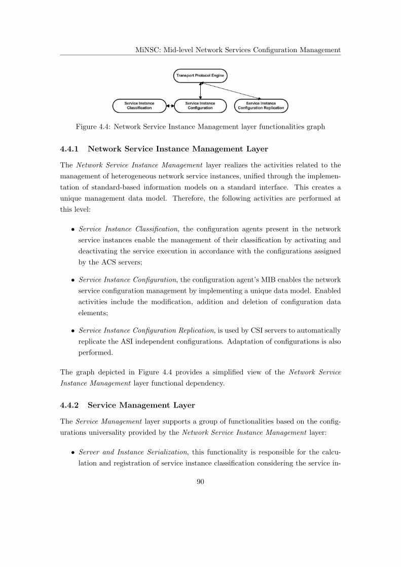
MiNSC: Mid-level Network Services Configuration Management
Figure 4.4: Network Service Instance Management layer functionalities graph
4.4.1 Network Service Instance Management Layer
The Network Service Instance Management layer realizes the activities related to the
management of heterogeneous network service instances, unified through the implemen-
tation of standard-based information models on a standard interface. This creates a
unique management data model. Therefore, the following activities are performed at
this level:
• Service Instance Classification, the configuration agents present in the network
service instances enable the management of their classification by activating and
deactivating the service execution in accordance with the configurations assigned
by the ACS servers;
• Service Instance Configuration, the configuration agent’s MIB enables the network
service configuration management by implementing a unique data model. Enabled
activities include the modification, addition and deletion of configuration data
elements;
• Service Instance Configuration Replication, is used by CSI servers to automatically
replicate the ASI independent configurations. Adaptation of configurations is also
performed.
The graph depicted in Figure 4.4 provides a simplified view of the Network Service
Instance Management layer functional dependency.
4.4.2 Service Management Layer
The Service Management layer supports a group of functionalities based on the config-
urations universality provided by the Network Service Instance Management layer:
• Server and Instance Serialization, this functionality is responsible for the calcu-
lation and registration of service instance classification considering the service in-
90

MiNSC: Mid-level Network Services Configuration Management
stances available, their weights (administratively defined) and the service redun-
dancy distribution level pretended. This functionality is performed by the CPS
servers, to distribute configuration servers, and by the ACS servers, to distribute
network service instances;
• Network Service Deployment, uses service meta-configurations to perform the au-
tomatic calculation of each service instance configuration (at the Network Service
Instance Management layer). In order to perform this task, Server and Instance
Serialization is used to compute the service deployment pattern, graduating the
service instances available;
• Instance Expansion, uses the configurations replicated to physically extend network
service instances, transforming candidate instances into active. This is performed
by load-balancing of configurations and is used to improve the managed service
scalability;
• Server Expansion, used to improve a configuration service scalability following the
same foundation as instance expansion functionality;
• Instance Migration, performed by the ACS servers to migrate a faulty ASI service
execution to a CSI using replicated configurations. This functionality improves
the managed service resilience, mitigating any instance failure identified by the
monitoring system;
• Server Migration, performed by CPS servers to migrate a faulty ACS service exe-
cution to a CCS using replicated configurations. This activity improves the con-
figuration management service resilience;
• Service Management, this activity is performed when the service meta-configurations
are changed and a new Network Service Deployment must be executed to compute
new service instance configurations;
• Server Configuration Replication, this mechanism is used by CCS to automati-
cally replicate (and adapt) the ACS independent configurations. This enables the
migration of configuration management activities between servers;
• Server Classification, the configuration agents present in the configuration servers
enable server classification management, activating and deactivating the manage-
ment activities based on the configurations assigned;
91
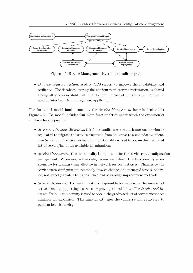
MiNSC: Mid-level Network Services Configuration Management
Figure 4.5: Service Management layer functionalities graph
• Database Synchronization, used by CPS servers to improve their scalability and
resilience. The database, storing the configuration server’s registration, is shared
among all servers available within a domain. In case of failures, any CPS can be
used as interface with management applications.
The functional model implemented by the Service Management layer is depicted in
Figure 4.5. The model includes four main functionalities under which the execution of
all the others depend on:
• Server and Instance Migration, this functionality uses the configurations previously
replicated to migrate the service execution from an active to a candidate element.
The Server and Instance Serialization functionality is used to obtain the graduated
list of servers/instances available for migration;
• Service Management, this functionality is responsible for the service meta-configuration
management. When new meta-configuration are defined this functionality is re-
sponsible for making them effective in network service instances. Changes to the
service meta-configuration commonly involve changes the managed service behav-
ior, not directly related to its resilience and scalability improvement methods;
• Service Expansion, this functionality is responsible for increasing the number of
active elements supporting a service, improving its scalability. The Service and In-
stance Serialization activity is used to obtain the graduated list of servers/instances
available for expansion. This functionality uses the configurations replicated to
perform load-balancing;
92

MiNSC: Mid-level Network Services Configuration Management
• Network Service Deployment, this functionality performs the automatic compu-
tation of each network service instance configuration, according to the defined
service meta-configurations. To implement this functionality, the Server and In-
stance Serialization is used to compute the service deployment pattern. Then,
Service Management functionality will deploy each instance configuration.
Given their importance, some functionalities shall be further discussed in the context of
each layer.
4.4.3 Server and Instance Configuration Replication
The configuration replication procedure (performed at both layers) takes advantage of
the configuration universality supported by MiNSC. Its usage should take into account
the following considerations:
• This procedure automatically and periodically copies the framework’s active ele-
ment configurations to a candidate element. Given the independence provided by
MiNSC’s abstracted configurations, no configuration translation is required, even
if source and destination elements use different implementations of software or
hardware;
• This procedure aims to be a preventive measure for the eventuality of existing
failures in MiNSC framework elements. In case of an active element failure, if its
configurations can be localized within a candidate element, the service execution
can proceed by replacing the faulty element. This operation is only possible due to
the abstraction provided by MiNSC’s configurations and it’s distributed architec-
ture with over-provisioning of network elements. This improves the framework’s
element resilience to failures;
• The configuration replication procedure also enables the realization of a load-
balancing mechanism between active and candidate elements. This is performed
by deactivating part of the active element’s independent configurations while ac-
tivating the same part at the candidate. This improves the service’s scalability;
• The replication procedure can be realized using two different alternatives: one
that includes only the active element’s static configurations, which is referred as
a lossy replication procedure, since the element’s dynamic configurations are not
considered; the other alternative includes the active element’s static and dynamic
93

MiNSC: Mid-level Network Services Configuration Management
configurations, which is referred to as a lossless replication procedure. The frame-
work element’s static configurations do not change during service operation and
defines its behavior, while dynamic configurations result from the service execution,
complementing static configurations (such as a cache);
• Changing the active and candidate classification (or state) at the Network Service
Instance Management layer (changing the managed service physical location) has
important implications from the network service’s client perspective. Therefore,
two different methods can be used to migrate network service instance execution:
– Changing the service instance’s physical and logical location, means
that the instance execution is migrated to a new physical location (new net-
work service instance). This also means that all remaining instances that
were not involved in the migration process, but have a configuration depen-
dence, must be updated to ensure the service configuration consistency. This
task is carried out by the ACS server responsible for the service configura-
tion management. Migrating a service instance (to a new location) means
that the service’ clients must also be updated. In order to perform this task,
the ACS server can use the client’s DHCP, updating the reference for a new
service instance instance. Then, a DHCP Server-Initiated Configuration Ex-
change [216] can be used to update the clients. If name to address translation
is required, Dynamic DNS [217–220] can be used to update the instance’s new
address;
– Changing the service instance’s physical location while keeping it’s
logical location means that the service instance execution is migrated to a
new physical location (new network service instance) however, the previous
instance’s logical location is kept. From the replication process perspective
not only are the service instance configurations replicated, but also the source
instance’s logical configurations (such as the network address, network mask,
gateway, among others) is as well. This means that, new logical configurations
must be assigned to the faulty node. From the replicated service instance
perspective, since its logical address is maintained, service clients and peer
service instances do not have to be updated.
Its important to note that the configuration replication procedure works in thigh relation
with the monitoring subsystem, which is responsible for the detection of service failures
(or performance degradation), to improve services resilience. A serialization algorithm
94

MiNSC: Mid-level Network Services Configuration Management
that, in accordance with the management domain goals, performs the service instance
classifications is also fundamental for the elaboration of the replication process.
Lossy Configuration Replication
A lossy configuration replication procedure uses MiNSC two layer infrastructure to repli-
cate a service instance static configurations (at the Network Service Instance Manage-
ment layer). In order for this to be performed, the service deployment procedure is
repeated using a modified set of service instances. When a service is deployed, the
service instances are classified as ASI or CSI. If failures are detected on a ASI and
a lossy configuration replication is requested, the service deployment is repeated, ex-
cluding the faulty instance hose configurations are deactivated. This way, the faulty
instance’s static configurations are replicated to a different instance that will continue
the execution of the managed service. For the execution of service deployment the service
meta-configurations, defined on MiNSC’s Service Management layer, are used.
Lossless Configuration Replication
The realization of a lossless configuration replication procedure means that the static
and dynamic configurations of framework elements are considered. In order for this to
happen, the element’s configurations are automatically and periodically replicated from
active to candidate. To promote a quicker migration of service execution, the replicated
configurations are also adapted to include the destination element’s details (such as
IP address, domain name, etc). Since the replication process includes the framework
element’s static and dynamic configurations, data losses are mitigated, which promotes
a smoother migration process.
4.4.4 Database Synchronization
MiNSC framework is based on the elaboration of configuration replication procedures
to improve service resilience and scalability at both management layers. In order for
this to be fulfilled, a synchronization mechanism must be used to ensure the integrity of
configuration data between active and candidate elements. At the CPS server level, a
synchronization mechanism is also used to disseminate the registration database among
all available CPS servers. As the management data to be synchronized is present in
MIBs, different alternatives can be used:
95

MiNSC: Mid-level Network Services Configuration Management
• At the configuration management agent level, the creation of a daemon, imple-
menting an SNMP server that automatically and periodically copies the active
element’s configurations, storing the replicated configurations locally;
• Create a special instrumentation, for the configuration agent’s MIB, that would
store service configuration in a database. Then any standard database replication
mechanism is used to synchronize active and candidate elements.
As previously referred, the first alternative was implemented for ASI and ACS config-
uration replication. This simplifies configuration agent’s implementation by using the
same configuration management protocol. However, this process gains higher complex-
ity when considering the synchronization of CPS, where any server can be the source or
destination of a synchronization procedure. On the other hand, this synchronization is
expected to be infrequent, occurring only when the configuration management servers
classification changes. So, the first alternative is costly and complex to implement be-
cause it requires periodic polling of all CPS server databases to search for updates. The
second alternative requires a conversion to a database technology, for the replication and
merge of different database versions, making the synchronization process also complex.
One variation of the first alternative is possible, through the use of notifications and lock
mechanisms:
1. When one of the CPS MIB is updated (adding, modifying or removing a reference),
it goes into a lock state (using VACM) and a notification is sent to the remaining
CPS informing about the existence of updates;
2. When the remaining CPS receive the notification they also lock their MIBs for
updates. Then they perform an update of their references;
3. When all CPS MIBs are updated, the source CPS update is made effective, and
the lock is released.
4.4.5 Network Service Deployment
The network service deployment is an important functionality supported by the man-
agement unification provided by the Network Service Instance Management layer and
the service oriented management approach provided by the Service Management layer.
This functionality uses the service meta-configurations (embedding the service behav-
ior pretended) to calculate and deploy each service instance configuration (including
96

MiNSC: Mid-level Network Services Configuration Management
the configurations dependencies when several servers cooperate in a distributed fash-
ion). MiNSC abandons the traditional server-oriented configuration management, using
a two-layer configuration representation, which enables a service oriented configuration
management approach. From a practical perspective, this means that a service is no
longer managed by individually controlling its supporting servers. In MiNSC, a service
is managed based on the overall behavior pretended which is latter translated into the
servers configuration. The network service deployment functionality is implemented by
ACS servers where the service meta-configurations are defined. The service management
information models implemented include:
• Support for the configuration of standard functionalities and other configurations
administratively required for service operation. This ensures homogeneous opera-
tion. When generating each service instance configuration their dependencies are
also ensured;
• Support the definition of service redundancy distribution level, that is used in
combination with a serialization algorithm, to physically distribute the network
service execution between the service instance available. This means that the
service redundancy distribution level is translated to the number of instances used
and their classification.
The network service deployment functionality ends with the configuration enforcement
into the corresponding network service instances, using a standard configuration man-
agement protocol.
4.4.6 Service Expansion
Service expansion is, such as the migration procedure, one of MiNSC’s most important
functionalities aiming to improve network and management service’s support for larger
scale domains. This functionality takes place at both management layers:
• At the Network Service Instance Management layer, the service expansion func-
tionality increases the number of network service instances used for a service de-
ployment, having direct influence on the service scalability. This activity increases
the number of ASI instances, load-balancing part of their independent configura-
tions replicated on CSI thus, extending the managed service physical support;
97

MiNSC: Mid-level Network Services Configuration Management
• At the Service Management layer, the service expansion functionality increases the
number of configuration management servers used for management tasks, having
direct implications on MiNSC’s scalability. This activity, carried out by the CPS
servers, increases the number of ACS servers activating part of their independent
configuration replicated on CCS.
It’s important to note that, regardless of the layer where it is implemented, service
expansion is capable of improving a service scalability by increasing the number of el-
ements. This is executed using the interface for the monitoring service, that, besides
referring the existence of scalability problems, also identifies faulty elements. Once the
problem is detected, MiNSC’s ACS and CPS server’s are responsible for acting accord-
ingly and perform the load-balancing process to try to mitigate the scalability limitation.
The load-balancing process deactivates part of the faulty element’s configuration while
activates the same part at a candidate element (using the independent configurations
previously replicated), which increases the number of active elements available. This
algorithm takes advantage of the configuration independence and can be applied regard-
less of specific service implementations. Besides enabling service extension (by dividing
the framework elements configurations), it is also possible to do the reverse operation,
concentrating configurations on a smaller number of active elements (and consequently
increasing the number of candidate nodes). This enables an efficient resource manage-
ment, using only active elements when they are required.
4.4.7 Server and Instance Serialization
To execute the framework element’s classification (as active or candidate) a serialization
algorithm is used. This thesis does not propose a final method to solve this problem,
as it depends on the specificities of the management domain where it is used. The
serialization algorithm is implemented with different goals, that are summarized by:
• Obtain a graduated list of network service instances used for the realization of
service deployment, based on the domain’s management goals. From the gradu-
ated list of network service instances and the service redundancy distribution level
defined, instances become classified as ASI or CSI. Such classification contains
important implications at the level of the network service’ scalability, resilience
and consumption of resources;
98
MiNSC: Mid-level Network Services Configuration Management
• The same process is used to classify the configurations management servers as ACS
and CCS. This procedure has a direct impact on MiNSC’s resilience, scalability
and resource consumption;
As referred, the implementation of this algorithm depends on the domain’s management
goals and possesses important implications at both the network and management ser-
vices. A few hints are provided as to the different strategies that may be followed when
addressing this problem:
• Manual serialization, where the administrator manually graduates MiNSC’s ele-
ments at both layers. While this is a viable alternative for small management
domains, where it is easy to keep track of the network elements classification,
this will not be adequate for large domains, where the implementation of manual
procedures is a complex task;
• Random serialization is a viable alternative to the manual classification by per-
forming an automatic graduation. However, since this procedure depends on a
random process, the unreliability of classifications can incur into instability and
unpredictability, which results in loss of control;
• Dynamic serialization is another automatic process, based on the definition of
weights, to create a more flexible graduation. In this process, costs are assigned to
instances and a cost minimization (or maximization) algorithm is used to choose
a minimum number of elements that is in accordance with the administrative
needs. This process possesses the advantage of benefitting from the fact that
costs associated to instances can be dynamically updated (using, for example, a
monitoring system), which means that the classification can change accordingly
to their performance, creating a dynamic instance serialization process taking into
consideration monitoring information.
The serialization of MiNSC’s elements is not limited to the previous methods. Any
method can be used as long as a graduated list is obtained. Each administrator should
be able to use the method that is most adequate to its management domain and know
how.
4.5 Resilience Improvement Method
The term resilience, applied to networks and services, was described [221, 222] as the
ability of a network to provide and maintain an acceptable level of service in the eventu-
99
MiNSC: Mid-level Network Services Configuration Management
ality of failures or constraints to a normal operation. For this to be fulfilled, the authors
add that network systems should include resilience provisioning methods. Besides, net-
worked systems should be continuously measured to find failures (or constraints), verify
service’s operational state and performance degradation. An acceptable level of ser-
vice is commonly described using SLA contracts, established between clients and service
providers using quantitative parameters such as service availability, throughput, latency,
packet loss, jitter, etc.
One way of improving the network service’s resilience is by ensuring a normal execu-
tion in all instances. A normal execution is defined by the SLA contract established and
verified by a monitoring system. The aim of MiNSC’s resilience improvement method
is to lower the impact of instance failure or performance degradation, that will impact
the final service level obtained. The resilience improvement method proposed is based
on the over-provisioning of network service instance and the periodic replication of in-
dependent configurations. This enables the framework elements execution migration in
case of failure or performance degradation.
4.5.1 Over-provisioning
MiNSC’s resilience improvement method is based on the over-provisioning of elements
classified as active or candidate. A network service is deployed according to the SLA
established which, among others, defines the number of elements physically supporting
the service (classified as active). Beyond this group of elements another group is defined,
classified as candidate, that periodically replicate active element’s configuration. When
failures (or performance degradation) is detected, candidate elements continue service
execution with minimum data losses.
4.5.2 Cost-aware Management
The over-provisioning of framework elements implies additional resources, which has a
financial repercussion. Nevertheless, candidate elements are expected to be shared with
other network elements, thus mitigating the cost. Also, the use virtualized elements can
reduce the total cost of ownership. The dynamic classification of active and candidate
elements represent a dynamic allocation of resources. This enables a more efficient
resource management, optimizing the cost involved.
100
MiNSC: Mid-level Network Services Configuration Management
4.6 Final Remarks
While simplifying the management of heterogeneous network service implementations,
MiNSC also improves management functionality. However, important implications are
also inherent to the application of this model. This will be identified and evaluated
through a perspective of future evolution.
4.6.1 Standard Management Information Models
The implementation of standard management information models has been extensively
used by several organizations such as:
• The IETF has defined several objects with different aims like:
– The RFCs 2819 [223], 3014 [224], 3413 [225], 3418 [226] mainly used for fault
management activities;
– The RFCs 3165 [227], 3413 [225], 3418 [226], 4133 [228] mainly used for
configuration management;
– The RFCs 2819 [223], 4502 [229], 4711 [230] mainly used for device perfor-
mance management;
– The RFCs 4668 [231], 4669 [232], 4670 [233] mainly used for security man-
agement.
• The DMTF, through the definition of CIM [234], provides standard definitions for
network management. Some of the concepts referenced by CIM include:
– Application, that represents the information required to deploy and manage
software products and applications;
– Database, that defines the management components for a database environ-
ment;
– Device, that manages the functionalities provided by hardware, including the
management of their configurations and state;
– Network, to manage the network’s communication connectivity, services and
protocol.
• The Tele-Management Forum (TMF) defined the Shared Information Data Model
(SID) [235] to build an information reference model and common vocabulary with
101

MiNSC: Mid-level Network Services Configuration Management
business concerns for the telecommunication industry. The SID information frame-
work is divided into eight layered domains, each one containing several business
entities called Aggregate Business Entity (ABE) such as Product, Service and Re-
source.
The implementation of standard management models aims to create a well defined group
of management references to be widely used and deployed, enabling the interoperabil-
ity and integration of heterogeneous management solutions, and the dissemination of
information between heterogeneous elements. This prevents the proliferations of non-
interoperable and proprietary network management frameworks and defines a common
group of functionalities that enables the creation of more efficient integrated management
applications. While the implementation of standard management models represents an
adequate method to integrate the management of heterogeneous elements, some prob-
lems are also found, which stem mainly from the standardization process, including the
ones referred in [236] and that include:
• The standardization processes takes a long time to be completed. The standard-
ization work groups are mainly composed by vendors and an agreement must be
reached among their requirements. So, standardization is a complex and long
process. Furthermore, the commercial pressure to introduce new functionalities
(representing a commercial leverage) incurs into the implementation of proprietary
management functionalities, unlikely to be widely used, thus creating management
interoperability problems;
• Finding the right level of abstraction in standard management models is a com-
plex task. A model cannot be too generic, since the definition of highly generic
concepts leads to many different interpretations, which may incur into interoper-
ability problems. On the other hand, the model cannot be too low-level because
their applicability is lost (losing their integration purpose). A trade-off must be
reached for model abstraction;
• The quality of the standard management models produced can be, at times, ques-
tionable for several reasons:
– As previously referred, finding the right level of abstraction is a complex task;
– The commercial pressure is a key reason to develop low-quality models;
– The technological experts are not interested in participating in the standard-
ization process due to commercial pressure.
102

MiNSC: Mid-level Network Services Configuration Management
From the previous reasons, and others identified in [236, 237], the implementation of
standard network management models can be problematic. The implementation of such
models is, historically, the most common way to avoid the proliferation of proprietary
management solutions. However, in order to be fulfilled, the standardization process
should be altered and made more expedite. In this sense, [236] proposes an approach
that simplifies standardization process relying on an iterative, multi-layer management
model. The proposed process can be summarized as follows:
1. A small team of experts in a given technology is gathered to build an initial con-
ceptual model known as the Lightweight Universal Information Model. This model
contains the core classes to manage a given technology including annotations that
capture the rational of the expert’s choices;
2. Then, management specialists derive management data models from the previous
information model;
3. Vendors implement the proposed data models and create management applications
to manage their products as soon as possible. Beta-test costumers are used to
experiment the management functionalities, reporting bugs or provide comments
that will help improve functionalities;
4. Further iterations improve the model specification based on the feedback provided
by the beta-testers. So, based on the feedback, the final Universal Information
Model is proposed;
5. New data models are specified for the diverse network management languages;
6. New implementations of the management data models are created by the vendors,
including their management applications to be later sold to a large customer base.
MiNSC and the Standard-based Service Management Models
One of the consequences inherent from the implementation of standard management
information models is the framework’s inability to manage the service’s non-standard
functionalities. Even though those do not represent the most important ones, they
commonly provide added-value features, that, associated with the standard functionali-
ties can differentiate offers from several vendors. Therefore, two important conclusions
should be taken: first, the software producers and device manufacturers will refrain from
creating advanced vendor-specific (non-standard) features because they will become non-
interoperable, and; if they really intend to implement their functionalities, this will push
103
MiNSC: Mid-level Network Services Configuration Management
them to work harder and faster to evolve the standards to include those functionalities.
These problems affect all frameworks implementing standard models, such as WBEM,
however, they enable the specification of non-standard extension models to support par-
ticular management needs. Obviously, this eliminates a sense of competition between
software implementers. On the other hand, the competition is gained at different dimen-
sions:
• From the perspective of the service provider, they become less limited to the group
of service implementations available, being able to select the most adequate with
the certainty that their management is ensured by means of standard models. This
makes network service implementers compete in terms of the performance of their
implementations and not in terms of number of extra functionalities;
• Most importantly, a new competition level is obtained at the management ap-
plication level. While, currently, the network service vendors commonly provide
service implementations and their correspondent management application, with
MiNSC, such dependency is not necessary. So, service implementations and man-
agement applications are autonomous, enabling an important competition at the
management application level and the functionalities they provide.
MiNSC uses minimalist standard-based service management information models, consid-
ering only the standard requirements for the service management and not vendor-specific
requirements. This simplifies the standardization process while enabling the specifica-
tion of service management models much quicker than finding an overall agreement on
complex models.
4.6.2 Integrated Network Management
It is important to note that MiNSC is not an integrated network management framework
as is FOCALE or WBEM, enabling the management of network elements implementing
heterogeneous management interfaces or data models. Such type of integration must be
necessarily conducted through the implementation of management translations. A dif-
ferent level of integration is proposed in MiNSC. That is, heterogeneous network service
implementation can be effectively managed based on the association of standard-based
service management information models and a standard management interface (repre-
senting unique data models), thus creating a new configuration management interface.
This eliminated management translations from the management system. MiNSC’s new
integrated management perspective includes important concerns related to the service
104

MiNSC: Mid-level Network Services Configuration Management
scalability and resilience, besides simplifying and potentiating automation of service
management tasks.
4.6.3 Confidentiality
Within MiNSC, a configuration management interface is used to provide the management
independence to support the heterogeneity of service implementations. However, in order
to make the management operations effective, access to important parts of the service
implementation is required. For this to occur, high levels of integration is required
between the management interface and the heterogeneous implementations, this provided
through the interface’s instrumentation. On the other hand, service implementers are
not willing to disclose their implementation details to third party implementers, which
endangers the effectiveness of the new configuration management interface.
In order to maintain service implementer confidentiality and still obtain high levels
of integration, the development of a management interface instrumentation must be the
service implementer’s responsibility. The network service implementers are in the best
position to achieve the best integration, between the configuration management interface
and the heterogeneous service implementations, without disclose the implementation
details.
4.6.4 Service Mobility
MiNSC’s distributed architecture introduces an important concept: the service’s physical
mobility. Its capability to dynamically change the number of supporting instances has
important implications, apart from those already referred (the service resilience and
scalability improvement) that includes:
• Service expansion can be used to improve the resource allocation, increasing the
number of elements when the number of requests increases and reducing their num-
ber when they are no longer needed (supporting effective resource management);
• The service’s physical mobility can also be used to improve the network’s efficiency
and performance. In large networks, the service can be moved closer to the place
where a high number of requests originate avoiding congesting the network and
performance degradation.
To effectively implement service mobility a serialization algorithm is required, that dy-
namically computes instance classification in thigh relation with a monitoring system.
105

MiNSC: Mid-level Network Services Configuration Management
4.7 Conclusion
In this chapter, MiNSC framework is completely described. It considers a new integrated
network service management perspective that does not rely on intermediary translation
mechanisms to manage heterogeneous network service implementations. MiNSC frame-
work is based on the implementation of standard-based service management informa-
tion models, enforced through a standard management interface, that creates a unique
data model eliminating the necessity of using management translations. The proposed
framework is built over two layers that also simplifies network service management,
by automating some management procedures and by enabling a more efficient resource
management. However, MiNSC’s proposal also includes some limitations, namely the
dependency on standardization processes and the required support of service vendors to
create adequate instrumentations for their products, according to MiNSC’s configuration
management interface.
106

Chapter 5
Implementation and Results
In this chapter a MiNSC based prototype is described and experimental results are
discussed as a mean to demonstrate the framework’s capabilities. The chapter also in-
cludes the standard-based information models for DNS service management, sub-divided
by MiNSC’s management abstraction layers, including their MIB implementations. The
development tools used for the prototype implementation are presented in the following
sections, along with the description of the main modules developed and algorithms ap-
plied by the framework elements. A set of experiments using the developed prototype
is also described and discussed. The results will vouch for the prototype usefulness and
MiNSC validity.
5.1 Motivation
The prototype was created to provide a deeper understanding as to the effectiveness
of the framework’s most important features, besides evaluating the feasibility of its
management model. The prototype implements the management of DNS service. This
chapter specifies the corresponding management information models used. Two main
components were developed for the experiments: a configuration server (ACS) and a
configuration agent to manage heterogeneous DNS server instances. With both elements,
features such as independence, resilience and scalability improvement methods were
experimented. The algorithms applied are also explained here. The developed prototype
represents an important contribution for the validation of the proposed network service
management model, serving as an initial reference for latter improvements.
107
Implementation and Results
5.2 Architecture
As previously mentioned, the MiNSC’s layered architecture relies on network service
instances (at the Network Service Instance Management layer) and configuration man-
agement servers (at the Service Management layer). In order to fulfill the tasks assigned
to each component, the architecture comprehends two fundamental elements: a configu-
ration management server that includes the required modules to support the server’s
classification (ACS, CCS, and CPS), mechanisms to improve network and management
services resilience and scalability, a standard network management interface to improve
management application interoperability and a module to manage the lower-layer ser-
vice instance’s configurations; a configuration management agent that includes the
required modules to support the service instance classification (ASI and CSI), mech-
anisms to improve network services resilience and scalability and a standard network
management interface that unifies the heterogeneous network service implementations
management based on a unique data model.
5.2.1 Configuration Management Server
The configuration management server is one of MiNSC’s key components for building
a distributed service configuration management framework. It is responsible for or-
chestrating the network service instance configuration, at the lower layer, ensuring that
they comply with behavior administratively defined. The configuration management
servers are implemented at the Service Management layer, through a distributed ar-
chitecture, that uses the management independence provided by the Network Service
Instance Management layer to simplify the management of heterogeneous network ser-
vice implementations. Figure 5.1 depicts the structure of a configuration management
server which is comprised by two parts:
• The SNMP Engine which enables communication between peer servers or ser-
vice instances, in the MiNSC prototype. The SNMP’s USM and VACM security
models use TCP transport mapping, thus providing a secure and reliable message
exchange;
• The MiNSC Engine is responsible for the execution of the advanced management
operations such as service instance configuration management, server classification,
instance serialization, service deployment, configuration replication procedure, ex-
ecution migration, among others.
108

Implementation and Results
Figure 5.1: MiNSC’s configuration management server structure
SNMP Engine
The SNMP Engine uses the manager’s traditional structure with a few simplifications.
Only SNMPv3 messages are supported (to ensure the message privacy, integrity and
communicating parties authentication) and only TCP transport mapping is enabled
(to ensure the reliability for the message exchange). Since the configuration manage-
ment servers are intended for mid-level operation, they include a Command Genera-
tor/Responder module to generate and respond to requests as well as a Notification
109

Implementation and Results
Generator/Receiver module to send and receive notifications. Depending on the origin
of the message, the Message/PDU Dispatcher module performs one of the following
operations:
• When a message is generated at the MiNSC Engine, it is transferred to the SNMP
Engine becoming an SNMP message PDU. The Message/PDU Dispatcher re-
ceives the PDU and uses the Message Processing subsystem to create an SNMPv3
compliant message where the PDU is encrypted (using DES algorithm) and the au-
thentication and integrity codes are added (using MD5 algorithm) to the message
headers. The SNMP message is then sent to the destination in an TCP segment;
• When the configuration management server receives a request message, the reverse
procedure is performed. The Message/PDU Dispatcher retrieves the SNMP mes-
sage from the TCP segment, sending it to the Message Processing subsystem to
process in accordance with the protocol version. The Security subsystem is then
used to decrypt the message, verify the sender’s authenticity and message integrity.
If the security verification is successfully completed, the message is returned to the
Message/PDU Dispatcher to be redirected to the Command Generator/Responder
module where the sender’s access permission is verified (using the VACM model).
If the permission is granted, the PDU is sent to the MiNSC Engine.
MiNSC Engine
The MiNSC Engine is responsible for performing the service management tasks at the
configuration server level. Some of its responsibilities include: deployment of network
service instance configurations, the orchestration of their behavior based on the service
meta-configuration administratively defined, support for a higher service management
abstraction to simplify the network service management activity, realization of a mecha-
nisms that uses the distributed architecture and configuration independence to improve
the configuration management service resilience and scalability. The MiNSC Engine uses
the SNMP Engine to exchange reliable and secure messages with remaining elements,
including the network service instances, management applications, peer configuration
servers and monitoring systems. At the MiNSC Engine, MIBs provide a standard in-
terface for the network service management and a database that is used to provide
a non-volatile storage (for configuration operations history, network service configura-
tion, instances and server classification, etc). The service management data models
implemented at both layers must be included in the MiNSC Engine, in order to enable
110

Implementation and Results
configuration management operations at both layers. The varied modules used by the
MiNSC Engine include:
• The Replication Daemon which is used when the server is classified as CCS and
has to periodically replicate the ACS server’s configuration. This daemon periodi-
cally synchronizes the CCS MIB with the ACS configuration either be replicating
configurations to replace a faulty ACS server or to implement load balancing;
• When new service configurations must be deployed the Server and Instance Se-
rialization module is used to find the best service deployment pattern according
to the available instances and the service redundancy distribution level defined on
the meta-configurations. This model applies an algorithm that, in accordance with
the administrative goals, provides a graduated list of service instances available;
• The Network Service Deployment module is responsible for taking the service meta-
configurations, and use the graduated list of service instances provided by the
Server and Instance Serialization to calculate each service instance configuration.
When performing the service deployment, the instance’s Replication Daemons are
also configured to activate the instance’s configuration replication procedures;
• The Server and Instance Expansion module is responsible for the configuration
management service and managed service physical extension. It performs a load-
balancing procedure between active and candidate elements using previously repli-
cated configurations. Upon receiving the indication for an expansion process (from
the monitoring system or management application), a given percentage of the ac-
tive element’s configuration is deactivated while activating the same part at the
candidate. This extends the amount of service resources by increasing the number
of active elements;
• The Server Configuration Replication module is responsible for managing the ex-
ecution of configuration replication procedures at the configuration server level.
When the server is classified as CCS this module controls the Replication Daemon
to automatically and periodically replicate the ACS configuration. Configuration
adaptation is also done, to include the CCS details;
• The Server and Instance Registration module is used for referencing the classifica-
tion of service instance and configuration management servers. It stores references
(for a domain) as to which instances and servers were used for service deployment;
111

Implementation and Results
• The Server and Instance Migration module uses the configurations replicated to
migrate the service execution from a faulty ACS to a CCS. This module is also
used to orchestrate the migration process at the managed service instance level.
Depending on the notification provided (by the monitoring system) this module
deactivates the service execution on the ASI while activating on the CSI using the
configuration previously replicated (when performing a lossless replication pro-
cess). The module also supports the lossy replication process by repeating the
service deployment with a different deployment pattern;
• The Instance Configuration Management module defines a generic interface for the
network service instance configuration management. This modules is used when
changes must be executed and is protocol independent;
• The Service Management module includes the managed objects instrumentation,
defined by the service management information model. When new meta-configurations
are defined, Network Service Deployment module is used to perform their deploy-
ment.
5.2.2 Configuration Management Agent
The configuration management agent is another relevant part of MiNSC’s framework.
It complements the framework elements by supporting the management unification of
heterogeneous network service implementations, based on the association of standard
technologies. The agent’s structure, depicted in Figure 5.2, is composed by three parts,
SNMP and MiNSC Engine and a group of heterogeneous network services instrumenta-
tions.
SNMP Engine
The SNMP Engine follows the agent’s traditional structure [215] implemented with two
important requisits: the agent only supports SNMPv3 messages (to ensure the authen-
ticity, confidentiality and message integrity of communicating parties) and only TCP
transport mapping is supported to ensure communication reliability. These impositions
are shared with the Configuration Management Server. So, SNMP messages are received
by the Message/PDU Dispatcher module using the TCP transport mapping. Those mes-
sages are then routed to the Message Processing subsystem for security verification in
accordance to the included message headers. Since the agent only supports SNMPv3
security mechanisms, the USM subsystem is used to verify message security dimensions.
112

Implementation and Results
Figure 5.2: MiNSC’s configuration management agent structure
The Message Processing subsystem returns the message to the Dispatcher module which
then routes the message to the MiNSC Engine after verifying the sender’s permission
(at the Command Responder module) by using the Access Control (VACM) subsystem.
MiNSC Engine
The MiNSC Engine realizes the configuration management operations on network service
instances based on independent representations. The following modules comprehend this
part of the agent:
113

Implementation and Results
• The Service Configuration Management Engine is responsible for receiving the ser-
vice configuration management PDUs and deployment of the effective management
of network service and replication daemon configurations;
• The Replication Daemon performs instance configuration replications by periodi-
cally copying the ASI configurations, adapting their content to the new instance
details while storing them in MIB tables for a quick service execution migration;
• The Instance Classification Management module manages the node’s instance clas-
sifications by locally starting, stopping or restarting the service execution according
to the defined configurations;
• The Instance Management is the first part of the Agent’s instrumentation which
contains the objects defined by the instance management information model to be
remotely managed using SNMP commands. The managed objets are organized in
MIBs.
• The Database is used to store important information in a non-volatile memory.
The database is used to store information as to the node’s instance classification,
configuration management history, service instances logs, configurations and other
relevant control information.
Network Services
The Network Services represents the part of the agent where the service’s instrumen-
tation is specified for universal implementations. The instrumentation supported was
divided into two parts: the first part, referred as Service Instrumentation, represents
a group of methods and representations commonly applied to all implementations. The
second part includes the implementation-specific representation of the Service Instru-
mentation.
5.3 Development Tools
MiNSC defines a new architecture to be implemented from scratch. From the group of
elements and functionalities defined, only an essential set was implemented to experi-
ment and validate the framework’s most relevant mechanisms. The prototype modules
were developed in Java Standard Edition (SE) version 1.7.0 using the NetBeans 6.9
Integrated Development Environment (IDE). MiNSC uses SNMP as the network man-
agement protocol and the SNMP4j API was used to implement the configuration agent
114

Implementation and Results
(and corresponding MIB) as well as the configuration servers. In order to specify the
configuration agent’s MIB, the MIB Designer application was used enabling a faster def-
inition of a syntactically correct MIB, described in SMI. To facilitate the configuration
agent’s MIB implementation based on the SNMP4j API, the AgenPro application was
used.
5.3.1 MIB Designer
The MIB Designer is a visual tool used for the creation and edition of MIB modules in
accordance with the SMI rules. Using a drag-and-drop interface, the MIB objects type
and structure are quickly defined without direct contact with SMI notation, associated
with an error checking tool thus ensuring a fast development of syntactically correct MIB
modules. The syntactical verification eliminates the most common mistakes inherent to
the language’s low-level definitions, which for larger projects can be highly complex to
manually debug. So, the MIB Designer IDE simplifies the MIB specification activity
providing varied functionalities that facilitate development tasks. The defined MIB
modules can be later exported in text, XML, XSD, SMIv1 or SMIv2 language. Some of
the features enabled by MIB Designer include the following:
• MIB modules created automatically in SMIv2;
• Conversion between SMIv1 and SMIv2;
• Flexible search options;
• Syntax verification at the level of MIB modules and objects;
• Flexibility edition including support for copy, cut, paste, spell checking, etc.
5.3.2 AgenPro
The AgenPro fills the gap between the MIB specification and the agent implementation
environment by generating the MIB implementation code (in Java or C++). So, the
AgenPro uses the MIB specification, provided by the MIB Designer (defined in SMI),
and a group of Code Generation Templates to define the output code which is compliant
with SNMP4j API, automatically generating the MIB’s basic instrumentation. This
tool enables a quick development of the agent following the MIB specification provided.
Some of the features provided by AgenPro include the following:
115

Implementation and Results
• Automatic generation of a MIB structure and objects code, simplifying the devel-
opment of a MIB’s instrumentation;
• Ensures the correct definition of the OID structure, table and object type defi-
nition, methods for table row management, definition of object value constraints,
notification and object instances value initialization;
• Enables the integration between MIBs and the configuration agent. MIBs can be
updated, added or removed with minimal changes to the agent. The agent can
also be changed without changing the MIB’s support;
• The code generation is based on the standard SMI specification, there’s no use of
specific conversion tags.
5.3.3 SNMP4j
The SNMP4j is an open source API for the development of the two basic SNMP elements
in Java: the Manager and the Agent. Some of the features provided by this API include:
• Two different APIs for building SNMP-based applications, one basic API support-
ing the basic Manager functionalities and an extended API for the development
of Agent specific functionalities;
• A Command Originator and Notification Originators/Receiver were defined specif-
ically for the creation of Manager applications while Notification Originator, Proxy
Forwarder and Command Responder functionalities were defined for the Agent ap-
plication;
• Both SNMP4j APIs support any of the three types of Message Processing subsys-
tems (MPv1, MPv2c and MPv3) for the processing messages of the three versions
of SNMP;
• The standard security subsystem, USM and VACM, are supported by both APIs;
• Support for MD5 and SHA-1 authentication algorithms as well as Advanced En-
cryption Standard (AES) 128, 192 and 256 privacy algorithms;
• Support for UDP, TCP and TLS transport mappings.
The code generated by AgenPro is based on SNMP4j API. This API was chosen because
it supports the SNMPv3 over TCP protocol, which was an important requirement of the
security and reliability of MiNSC’s configuration management protocol.
116
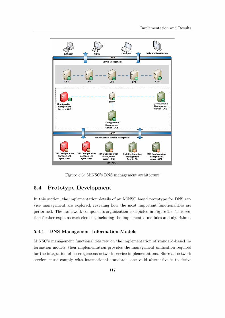
Implementation and Results
Figure 5.3: MiNSC’s DNS management architecture
5.4 Prototype Development
In this section, the implementation details of an MiNSC based prototype for DNS ser-
vice management are explored, revealing how the most important functionalities are
performed. The framework components organization is depicted in Figure 5.3. This sec-
tion further explains each element, including the implemented modules and algorithms.
5.4.1 DNS Management Information Models
MiNSC’s management functionalities rely on the implementation of standard-based in-
formation models, their implementation provides the management unification required
for the integration of heterogeneous network service implementations. Since all network
services must comply with international standards, one valid alternative is to derive
117

Implementation and Results
management information models from those standard definitions. Their implementa-
tion on a standard management interface creates a management unification based on a
unique data model. Such models enable the management of any service implementation
that works in accordance to the standards, supporting the management of their stan-
dard functionalities and ignoring all the vendor-specific functionalities provided. The
management information models based on the service’s standard parameters creates
minimalist models that focus on the essential part of service management. This per-
spective goes against the traditional method of building standard management models,
which commonly create a complete set of features to support most of the vendor’s specific
functionalities. The application of such models increases their implementation complex-
ity besides resulting in a slower standardization process, (since an agreement must be
achieved among all vendor requirements as explained in [236]). The implementation
of MiNSC’s simple service management information models has important advantages,
simplifying the creation of the models and their implementation.
Two DNS management information sub-models are described in the following sec-
tions. These models are based on the study of DNS service standard descriptions and
aims to support essential DNS management functionalities. It enables independent DNS
management and serves as a starting point for the development of more advanced models,
requiring further development in order to support advanced functionalities.
DNS Instance Management Information Model
The DNS instance management information model is used in MiNSC’s Network Service
Instance Management layer, enabling the management of the service’s standard func-
tionalities in terms of universal implementations. The deployment of this model provides
a semantic unification that overcomes the need to implement semantic or syntactic map-
pings when creating integrated management applications. The proposed model is rep-
resented in Figure 5.4 and enables the management of the most essential functionalities
of DNS instances such as standard resource records, caching, recursion and notifica-
tion support. The model is built around the definition of DNS Zones to organize the
instance’s configurations.
The DNS instance management information model is depicted in Figure 5.4, using
a UML class diagram, where each class represents a well defined group of DNS instance
configuration parameters. These classes are related to each other through composition
relations, meaning that the child class life cycle is limited to the parent life cycle. This
property is also true for configuration management, where some configurations only make
118

Implementation and Results
Figure 5.4: DNS instance management information model
sense in the presence of others (for example the relation between DNS resource records
and the Zone configuration).
Globally, the proposed model is composed by the following parts:
• The DNS instance management information model supports the configuration of
the instance’s static and dynamic configurations. The static configurations are
represented by the Zone that characterize the DNS service being provided. These
configurations do not change during the regular service operation (or have infre-
quent changes). The service instance’s dynamic configurations are represented
by the Cache, and include standard resource records gathered from the server’s
operation;
• The entire model is built around the Zone class definition. It includes the at-
tributes to characterize the domain name server behavior as well as the elements
requiring name to address translation, represented through the standard DNS re-
source records;
119

Implementation and Results
• The DNS resource records are the basic data elements used in the naming system.
Some of the most common resource records (defined in [238]) are included in the
model, such as A, CNAME, MX, NS, PTR and SOA. This model also represents
the DNS standard directives defined in [238,239];
• The Behavior class enables the definition of the DNS instance behavior for a DNS
Zone. Among the several attributes presented, the following have enhanced re-
sponsibility for the behavior definition:
– The Type attribute defines the instance behavior for a DNS Zone in accor-
dance with the primary or secondary classification [238];
– The Notification attribute enables the usage of the notification mecha-
nism [240]. When DNS Zone configurations are updated the notification
mechanism is used to inform secondary name servers about the necessity to
execute a Zone transfer;
– The Recursion attribute describes whether or not the name server accepts
recursive queries [238] or not;
– The Caching attribute enables the realization of caching [239, 241] at the
name server level. If so, it also defines the type of caching (positive or nega-
tive);
– The PrimaryID and SecondaryList attributes identifies the primary and
secondary name servers respectively.
The DNS instance management information model was implemented in a MIB, being
decomposed into SMI tables and table row pointers. The MIB structure defined is only
partially depicted in Figure 5.5 due to space constraints, complete representation can
be found in [242]. The object’s tree was built under the Experimental object (OID
1.3.6.1.3) and it clearly separates the objects for the MiNSC’s network service instance
configuration management operations (OID 1.3.6.1.3.1) and the SMON network instance
monitoring objects (OID 1.3.6.1.3.2). In this manner, the MIB supports the objects for
the two most basic instance management operations. The objects defined for the in-
stance configuration management include, namely the DNS (OID 1.3.6.1.3.1.1), DHCP
(OID 1.3.6.1.3.1.2) and E-mail (OID 1.3.6.1.3.1.3) defining the root for their correspond-
ing instances management information models. The DNS node management information
model (previously depicted in Figure 5.4) was placed under the DNS object, being de-
composed into tables and table row pointers to model the composition relation of the
classes. The model decomposition showed that a table was created for each class defined:
120

Implementation and Results
Figure 5.5: DNS instance management MIB
121
Implementation and Results
• zoneTable represents the Zone class MIB implementation, defined through a ta-
ble that contains table row pointers for the model’s remaining tables (like behav-
iorTable, directivesTable, behaviorTable, aTable, nsTable and soaTable);
• directivesTable represents theDirectives class MIB implementation, defined through
a table that contains the DNS directives’ standard parameters like origin, include
and ttl ;
• behaviorTable (OID 1.3.6.1.3.1.1.3.1) represents the Behavior class MIB implemen-
tation, defined through a table containing the Zone’s behavior definition parame-
ters like the zoneId, type, recursion, notification, primaryId and secondaryList ;
• The records (OID 1.3.6.1.3.1.1.4) represents the Records class MIB implementation,
defined through an object that is the root for a MIB tree containing the standard
DNS resource records representations:
– aTable represents the A class MIB implementation, defined through a ta-
ble that contains the A resource record standard parameters like domain-
Name, ttl and ipAddr. It’s important to notice that the importIndex (OID
1.3.6.1.3.1.1.4.1.1.1.1) enables the association of several A resource record
representations to a DNS Zone, containing a unique identifier;
– nsTable represents the NS class MIB implementation, defined through a ta-
ble containing the NS resource record standard parameters like domainName,
ttl and nameServer ;
– soaTable represents the SOA class MIB implementation, defined through
a table that contains the SOA resource record standard parameters like do-
mainName, ttl, mName, rName, serialNumber, refreshInterval, retryInterval,
expireInterval and defaultTtl ;
An additional parameter called rowStatus was included in all tables in order to perform
table’s row management.
DNS Service Management Information Model
The DNS service management information model is used in MiNSC’s Service Manage-
ment layer, enabling the automation of some configuration management tasks, as well as,
management simplification provided through a service-oriented management approach.
The proposed model is depicted in Figure 5.6, using a class diagram, being composed of
the following classes:
122

Implementation and Results
• The Domain class defines the DNS service authority domain. The authority at-
tribute represents the DNS service domain’s identification while the parent at-
tribute represents the domain’s parent name identification;
• The Operation class describes service behavior. The following attributes are in-
cluded:
– The Redundancy-Distribution attribute is used for the calculation of the
service deployment pattern. Its value is used to calculate the DNS instances
classification (the number of ASI and CSI) as well as their distribution;
– The Notification attribute enables the usage of the notification mechanism
on primary name servers. The notification attribute is either defined with a
true or false value;
– The Caching attribute enables the DNS instance’s caching mechanisms. It’s
defined with none, positive, negative or both values, referring to the types of
caching supported;
– The Volatility attribute refers to the expected variation for the primary
name server Zone configuration. A high volatility translates into a lower
refresh interval value, meaning that the secondary name servers must update
their configurations more frequently;
– The Persistence value refers to the persistence that secondary name servers
present when failing to update the Zone configuration. A high persistence
value defines a lower retry interval, meaning that the secondary name server
waits less time to contact the primary name server;
– The Validity attribute refers to the duration of the Zone configurations
transferred to a secondary name server. A high validity value defines a large
expiry value, which corresponds to the time elapsed of the last successful Zone
configuration transfer;
Figure 5.6: DNS service management information model
123

Implementation and Results
– The Duration attribute refers to the duration desired for the DNS resource
records when cached. A high duration means that they are maintained in
cache for a larger period of time.
• The Elements class enables the representation of network elements requiring name
to address translation such as a web-server, e-mail server, printer and others. The
following attributes are defined for this class:
– The Type attribute identifies the type of network element requiring name to
address translation such as Printer, WebServer, EmailServer, etc;
– The Name attribute refers to the network element’s domain name;
– The Content attribute refers to the network element’s address.
More trees were defined under the Experimental object (OID 1.3.6.1.3). One identifying
the root of the objects for the network service configuration management operations
(OID 1.3.6.1.3.3) and the other to include the objects for the network service’s monitoring
operations (OID 1.3.6.1.3.4) as depicted in Figure 5.7. To support the configuration
management of several network services, a tree was defined for some services: DNS
(OID 1.3.6.1.3.3.1), DHCP (OID 1.3.6.1.3.3.2) and E-mail (OID 1.3.6.1.3.3.3). The DNS
service management information model was represented under the DNS management
object by using tables and table row pointers, including the following:
• serviceTable represents the DNS Service class MIB implementation, containing the
table row pointers for the remaining tables, namely doaminTable, operationsTable
and elementTable;
• domainTable represents the Domain class MIB implementation, including objets
supporting values for the parent and authority attributes;
• operationsTable represents the Operation class MIB implementation, including ob-
jets supporting values for the redundancy-distribution, notification, caching, volatil-
ity, persistence, validity and duration attributes;
• elementsTable represents the Elements class MIB implementation, including ob-
jets supporting values for the name, content and type attributes. Due to the fact
that one service may contain several elements, the importIndex identifies the cor-
responding serviceTable row;
124

Implementation and Results
Figure 5.7: DNS service management MIB
5.4.2 Configuration Management Server
The MiNSC’s configuration management server architecture is depicted in Figure 5.1 and
is globally composed by two parts: the SNMP Engine that provides a reliable and secure
125

Implementation and Results
Figure 5.8: Server and Instance Registration MIB
management of network service instance configurations through the exchange of SNMPv3
messages; the MiNSC Engine, that was built on top of the SNMP Engine, provides a
group of management functionalities that includes management simplification, resilience
and scalability improvement methods. The functionalities provided are brought by a
group of modules already referred in this chapter. The following sections focus on the
exploration of the MiNSC Engine details. The SNMP Engine functionalities, which
are well known and described in international standards, were implemented using the
SNMP4j API. The protocol used for authentication was HMAC-MD5-96 and the CBC-
DES protocol was used for privacy. The VACM access control mechanism was not
implemented for the prototype since it is irrelevant in terms of proof of concept.
Server and Instance Registration
The Server and Instance Registration module provides an important functionality, main-
taining references about the configuration servers classification (ACS and CCS) in an
MIB. The MIB structure used by this module is depicted in Figure 5.8 and includes the
following tables:
• The pointingTable, references rows in other tables, namely the serviceTable and
serverTable. This enables the association of services to server/instance’s classifi-
cation;
• The serviceTable, enables identification of a service;
• The serverTable, lists classifications of server/instances.
126

Implementation and Results
Figure 5.9: Service Replication MIB
On CPS servers, the Server and Instance Registration module works in cooperation
with a Database Synchronization module, ensuring the reference data consistency by
propagating the information among all servers. This synchronization mechanism may
be implemented using locks to CPS’s MIB. However, for this prototype the Database
Synchronization module was not developed, being addressed in future work.
Replication Daemon
The Replication Daemon module represents a process being performed by CCS servers,
responsible for periodically replicating the ACS server configurations, with the purpose
of improving the configuration management service resilience and scalability. The CPS
servers are responsible for setup the Replication Daemon operation, using the Service
Replication MIB with the structure depicted in Figure 5.9 composed by the following
objects:
• The serviceId identifies the network service to be replicated (such as DNS, DHCP,
E-MAIL), which refers to specific MIB tree;
• The nodeId identifies the configuration server to be the source of the replicated
meta-configurations;
• The periodicity defines the time period in which the CCS server retrieves the ACS
service meta-configurations.
127

Implementation and Results
The replicationTable defines a list of ACS servers whose service meta-configurations
are periodically replicated to the CCS Service Management MIB. However, not only
the service meta-configurations are replicated, the service instance’s classification stored
in the ACS’s Server and Instance Registration MIB (1.3.6.1.3.5) are also replicated,
enabling the configuration management execution migration.
DNS Parameters
When deploying a DNS service, the conversion of some high-level meta-configuration
parameters is required for the instances low-level configurations, in accordance with
administratively defined requirements. Values defined for the service redundancy distri-
bution level, volatility, persistence, validity and duration (defined as high, medium and
low) must generate numeric values corresponding to the number of active and candidate
instances, their distribution and other DNS standard configurations such as refresh,
retry, expire and Time-to-Live (TTL) values. To enable a more flexible definition, a
DNS Parameters MIB (depicted in Figure 5.10) was created, being composed by the
following tables:
• distributionTable that maps from the redundancy distribution level (DNS service
meta-configurations) to the percentage of active instances required and their dis-
tribution pattern (such as static, random, minimization-cost or maximization-cost
for example). In this prototype the following configurations were used:
– level: High, activePercentage: 30, distribution: static;
– level: Medium, activePercentage: 50, distribution: static;
– level: Low, activePercentage: 90, distribution: static.
• volatilityTable that maps from the volatility level (DNS service meta-configurations)
to the value used for the DNS SOA refresh:
– level: High, value: 3400;
– level: Medium, value: 3600;
– level: Low, value: 3800.
• persistenceTable that maps from the persistence level (DNS service meta-configurations)
to the value used for the DNS SOA retry:
– level: High, value: 400;
128

Implementation and Results
– level: Medium, value: 600;
– level: Low, value: 800.
• validityTable that maps from the validity level (DNS service meta-configurations)
to the value used for the DNS SOA expire:
– level: High, value: 86000;
– level: Medium, value: 86400;
– level: Low, value: 86800.
• durationTable that maps from the duration level (DNS service meta-configurations)
to the value used for the DNS TTL:
– level: High, value: 3400;
– level: Medium, value: 3600;
– level: Low, value: 3800.
Monitoring
MiNSC’s configuration management servers include a interface to the monitoring system.
This interface is used to informe as to the need to execute a configuration management
operation. In this sense, a MIB table was created (Monitoring MIB (1.3.6.1.3.4.1.1.1))
to define such interface, describing a configuration management operation to be per-
formed on a instance/server. The table structure of the Monitoring MIB is depicted in
Figure 5.11 and is composed by the following objects:
• The serviceId identifies the network service (such as DNS, DHCP, E-MAIL);
• The instanceId identifies the network service instance or configuration management
server requiring a configuration management operation;
• The operation identifies the configuration management operation to be performed.
Such operation might be the execution migration, service expansion, deactivation
of configurations or other to be added in the future.
It is important to note that this interface was created with the purpose of experimenting
some of MiNSC’s management functionalities. It should be refined when the specification
of the monitoring system is completed.
129
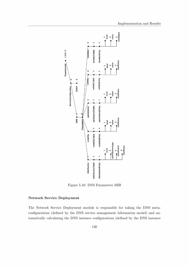
Implementation and Results
Figure 5.10: DNS Parameters MIB
Network Service Deployment
The Network Service Deployment module is responsible for taking the DNS meta-
configurations (defined by the DNS service management information model) and au-
tomatically calculating the DNS instance configurations (defined by the DNS instance
130

Implementation and Results
management information model) including their configuration dependencies. For the
developed prototype, deployment was performed using the procedure represented in
Algorithm 1. This algorithm receives an index (i) identifying the corresponding meta-
configurations in serviceTable (DNS Service Management MIB (1.3.6.1.3.3.1)), and ex-
ecutes the following procedure:
1. Using the GetDNSInstancesRegistered method, the list of DNS instances available
is retrieved from the ACS’s Server and Instance Registration MIB (1.3.6.1.3.5);
2. If at least one DNS instance is available, the service deployment is executed;
3. The DNS service meta-configuration is retrieved (from DNS Service Management
MIB (1.3.6.1.3.3.1)) using the GetDNSServiceConfiguration method;
4. The DNS service administrative parameters defined are retrieved from the DNS
Parameter MIB (1.3.6.1.3.3.1.6) using the GetDNSServiceParameters method;
5. The service instance serialization algorithm is applied using the ApplyInstancesSe-
rialization method. It computes the DNS instances classification in accordance
with the service redundancy distribution level desired, the DNS parameters de-
fined and the number of DNS instances available;
6. The AssignRedundancyClassification method uses the DNS instances classified as
active to define their role, one as primary and the remaining as secondary name
servers;
Figure 5.11: Monitoring MIB
131

Implementation and Results
7. The RegisterInstancesClassification method is used to store the instance classifica-
tion at the Server and Instance Registration MIB (1.3.6.1.3.5). The maintenance
of the instance’s registration in an MIB enables the complete ACS service config-
uration replication;
8. The GenerateActiveDNSInstancesConfigurations method takes the DNS service
meta-configuration, the DNS parameters defined and the instances classified as ac-
tive to automatically calculate the ASI configurations, including their configuration
dependencies;
9. The GenerateCandidateDNSInstancesConfigurations method takes the DNS ser-
vice meta-configuration and the instances classified as active and candidate to
calculate instance configuration replication procedures;
10. For each active instance configuration generated, the DeployDNSInstanceConfigu-
ration method is used to securely deploy the DNS instance configurations into the
DNS Instance Management MIB (1.3.6.1.3.1.1). The ListenNotification method is
used to ensure that the DNS instance configurations were effectively applied while
waiting for instance notification;
Algorithm 1 DNS service deployment
n ⇐ GetDNSInstancesRegistered()if n > 0 then
service ⇐ GetDNSServiceConfiguration(i)parameters ⇐ GetDNSServiceParameters()n ⇐ ApplyInstancesSerialization(service, parameters, n)n ⇐ AssignRedundancyClassification(n)RegisterInstancesClassification(n)activezoneList ⇐ GenerateActiveDNSInstancesConfigurations(service,parameters, n)replicationTable ⇐ GenerateCandidateDNSInstancesConfigurations(service, n)for zone ∈ activezoneList do
DeployDNSInstanceConfiguration(zone, n)ListenNotification(zone)
end forfor row ∈ replicationTable do
SetCandidateReplicationTable(row, n)ListenNotification(row)
end forend if
132
Implementation and Results
11. For each candidate instance configuration generated, the DeployCandidateRepli-
cationTable method is used to securely deploy the replication table content into
the Instance Replication MIB (1.3.6.1.3.1.4.1). The ListenNotification method was
used to ensure that the DNS instance configurations were effectively applied while
waiting for instance notification.
Instance Migration
The Instance Migration module was implemented in the prototype to improve the man-
aged service resilience to instance failure. This module uses the network service instance
independent configurations, periodically replicated in candidate, and the Network Ser-
vice Deployment module to enable the service execution migration in case of failure.
Regarding the maintenance (or not) of the service instance dynamic configurations two
types of procedures might be performed: lossy or lossless.
In a lossy DNS instance execution migration procedure only the service instance’s
static configurations are considered, dynamic configurations are lost. To perform this
procedure, the steps described in Algorithm 2 are executed. The algorithm input pa-
rameters required include the service index (i) in the DNS Service Management MIB
(1.3.6.1.3.3.1) and the IP address of the faulty instance (instanceId):
1. The DNS service meta-configuration (defined at the DNS Service Management
MIB (1.3.6.1.3.3.1)) is retrieved using the GetDNSServiceConfiguration method;
2. Using the GetDNSInstancesRegistered method, the DNS instances used for the
service deployment are retrieved from the Server and Instance Registration MIB
(1.3.6.1.3.5);
3. The periodic instance configuration replication procedure, defined by the service
deployment, is suspended at the CSI using the StopCandidateReplication method.
This method sets Instance Replication MIB (1.3.6.1.3.1.4.1) rows for deletion;
4. The instances classification registered by the service deployment, at the Server and
Instance Registration MIB (1.3.6.1.3.5), are erased using the DeleteInstancesReg-
istration method;
5. The service execution, at the faulty instance (instanceId), is suspended using the
UndeployDNSInstanceConfiguration method. This methods erases configurations
by setting DNS Instance Management MIB (1.3.6.1.3.1.1) rows for deletions;
133

Implementation and Results
Algorithm 2 Lossy DNS instance execution migration
service ⇐ GetDNSServiceConfiguration(i)n ⇐ GetDNSInstancesRegistered(i)StopCandidateReplication(n)DeleteInstancesRegistration(i)UndeployDNSInstanceConfiguration(service, instanceId)n ⇐ RemoveDNSInstance(n, instanceId)if n > 0 then
parameters ⇐ GetDNSServiceParameters()n ⇐ ApplyInstancesDistribution(service, parameters, n)n ⇐ AssignRedundancyClassification(n)RegisterInstancesClassification(n)activezonelist ⇐ GenerateActiveDNSInstancesConfigurations(service,parameters, n)replicationTable ⇐ GenerateCandidateDNSInstancesConfigurations(service, n)for zone ∈ activezonelist do
DeployDNSInstanceConfiguration(zone, n)ListenNotification(zone)
end forfor row ∈ replicationTable do
DeployCandidateReplicationTable(row, n)ListenNotification(row)
end forend if
6. From the group of instances previously used for service deployment, the faulty
instance (instanceId) is removed using the RemoveDNSInstance method;
7. If at least one service instance is still available, a new service deployment is exe-
cuted;
8. The DNS service parameters administratively defined were retrieved from the DNS
Parameter MIB (1.3.6.1.3.3.1.6) using the GetDNSServiceParameters method;
9. For the remaining available instances, the service instance serialization algorithm
is applied using the ApplyInstancesSerialization method. It computes the DNS
instances classification in accordance with the service redundancy distribution level
desired, the DNS parameters defined and the number of DNS instances available;
10. The AssignRedundancyClassification method uses the active instance classification
to define the primary and secondary name servers roles;
134
Implementation and Results
11. The RegisterInstancesClassification method stores the instances classification at
the Server and Instance Registration MIB (1.3.6.1.3.5);
12. The GenerateActiveDNSInstancesConfigurations method takes the DNS service
meta-configuration, the DNS parameters defined and the active instances to au-
tomatically calculate the ASI configurations, including their configuration depen-
dency;
13. The GenerateCandidateDNSInstancesConfigurations method takes the DNS ser-
vice meta-configuration and the active and candidate instances to calculate in-
stance configuration replication procedures;
14. For each active instance configuration generated, the DeployDNSInstanceConfigu-
ration method was used to securely deploy the DNS configurations into the DNS
Instance Management MIB (1.3.6.1.3.1.1). The ListenNotification method is used
to ensure that the DNS instance configurations were effectively applied, waiting
for instance notification;
15. For each candidate instance configuration generated, the DeployCandidateReplica-
tionTable method was used to securely deploy the replication table contents into
the Instance Replication MIB (1.3.6.1.3.1.4.1). The ListenNotification method is
used to ensure that the replication table configurations were effectively applied.
When performing a lossless DNS instance execution migration procedure, both static
and dynamic configurations of DNS instances are considered. For this to be fulfilled,
Algorithm 3 is implemented, requiring the identification of the service index (i) in the
DNS Service Management MIB (1.3.6.1.3.3.1) and the IP address of the faulty instance
(instanceId):
1. The DNS service meta-configuration (defined at the DNS Service Management
MIB (1.3.6.1.3.3.1)) is retrieved using the GetDNSServiceConfiguration method;
2. Using the GetDNSInstancesRegistered method, the DNS instances used for the
service deployment are retrieved from the Server and Instances Registration MIB
(1.3.6.1.3.5);
3. The periodic instance configuration replication procedure, defined by the service
deployment, is suspended at the CSI using the StopCandidateReplication method.
This method sets Instance Replication MIB (1.3.6.1.3.1.4.1) rows for deletion;
135
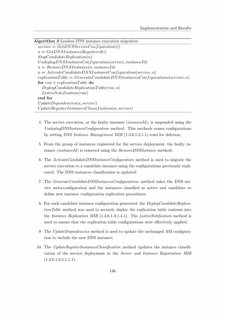
Implementation and Results
Algorithm 3 Lossless DNS instance execution migration
service ⇐ GetDNSServiceConfiguration(i)n ⇐ GetDNSInstancesRegistered(i)StopCandidateReplication(n)UndeployDNSInstanceConfiguration(service, instanceId)n ⇐ RemoveDNSInstance(n, instanceId)n ⇐ ActivateCandidateDNSInstanceConfiguration(service, n)replicationTable ⇐ GenerateCandidateDNSInstancesConfigurations(service, n)for row ∈ replicationTable do
DeployCandidateReplicationTable(row, n)ListenNotification(row)
end forUpdateDependencies(n, service)UpdateRegisterInstancesClassification(n, service)
4. The service execution, at the faulty instance (instanceId), is suspended using the
UndeployDNSInstanceConfiguration method. This methods erases configurations
by setting DNS Instance Management MIB (1.3.6.1.3.1.1) rows for deletion;
5. From the group of instances registered for the service deployment, the faulty in-
stance (instanceId) is removed using the RemoveDNSInstance method;
6. The ActivateCandidateDNSInstanceConfiguration method is used to migrate the
service execution to a candidate instance using the configurations previously repli-
cated. The DNS instances classification is updated;
7. The GenerateCandidateDNSInstancesConfigurations method takes the DNS ser-
vice meta-configuration and the instances classified as active and candidate to
define new instance configuration replication procedures;
8. For each candidate instance configuration generated, the DeployCandidateReplica-
tionTable method was used to securely deploy the replication table contents into
the Instance Replication MIB (1.3.6.1.3.1.4.1). The ListenNotification method is
used to ensure that the replication table configurations were effectively applied.
9. The UpdateDependencies method is used to update the unchanged ASI configura-
tion to include the new DNS instance;
10. The UpdateRegisterInstancesClassification method updates the instance classifi-
cation of the service deployment in the Server and Instance Registration MIB
(1.3.6.1.3.5.1.1.1).
136

Implementation and Results
Instance Management
The Instance Management module provides a generic interface for the network service
instance configuration management. This interface is independent of the underlying
management protocol and includes the following attributes:
• InstanceId, identifying the network service instance to be managed;
• ObjectOID, identifying the object to be managed according to the instance man-
agement information model;
• Operation, identifying the management operation to be performed: ADD, SET,
GET, DELETE;
• Value, is an optional attribute used to change the object’s value.
Server and Instance Expansion
The Server and Instance Expansion module is used to increase the number of elements
supporting the network or management service. This process uses the independent con-
figurations replicated at both layers to divide the service execution between active and
candidate elements. For the expansion process, a percentage of the active element’s
configurations are migrated, suspended in the active element and activated in the candi-
date element. This creates a new active element extending the network or management
service resource support. The reverse operation can also be created, concentrating the
active elements configurations thus reducing their number. The procedure which enables
a DNS instance expansion is described in Algorithm 4 and includes the following steps:
1. The DNS service meta-configuration (defined at the DNS Service Management
MIB (1.3.6.1.3.3.1)) is retrieved using the GetDNSServiceConfiguration method;
2. Using the GetDNSInstancesRegistered method, the DNS instances used for the
service deployment are retrieved from the Server and Instances Registration MIB
(1.3.6.1.3.5);
3. The periodic instance configuration replication procedure, defined by the service
deployment, is suspended at the CSI using the StopCandidateReplication method.
This method sets Instance Replication MIB (1.3.6.1.3.1.4.1) rows for deletion;
4. The service execution, at the active instance to be extended, is modified using
the UndeployDNSInstanceConfiguration method that erases a percentage of DNS
Zone configurations (DNS Instance Management MIB (1.3.6.1.3.1.1));
137

Implementation and Results
Algorithm 4 DNS instance expansion
service ⇐ GetDNSServiceConfiguration(i)n ⇐ GetDNSInstancesRegistered(i)StopCandidateReplication(n)configuration ⇐ UndeployPartDNSInstanceConfiguration(service, instanceId,percentage)n ⇐ ActivateCandidateDNSInstanceConfiguration(configuration, n)replicationTable ⇐ GenerateCandidateDNSInstancesConfigurations(n)for row ∈ replicationTable do
DeployCandidateReplicationTable(row, n)ListenNotification(row)
end forUpdateDependencies(n, service)UpdateRegisterInstancesClassification(n, service)
5. The previously erased configurations, at the active instance to be extended, are
activated in one of the candidate instances using the ActivateCandidateDNSIn-
stanceConfiguration method. This creates a new active instance;
6. The GenerateCandidateDNSInstancesConfigurations method takes the instances
classified as active and candidate to calculate new instance configuration replication
procedures;
7. For each candidate instance configuration generated, the DeployCandidateReplica-
tionTable method was used to securely deploy the replication table contents into
the Instance Replication MIB (1.3.6.1.3.1.4.1). The ListenNotification method is
used to ensure that the replication table configurations were effectively applied;
8. The UpdateDependencies method is used to update the unchanged ASI configura-
tion to include the new DNS instance;
9. The UpdateRegisterInstancesClassification method updates the instance classifi-
cation of the service deployment in the Server and Instance Registration MIB
(1.3.6.1.3.5).
Server and Instance Serialization
The Server and Instance Serialization module enables the calculation of the framework
element’s most adequate distribution according to their number and the defined level of
redundancy distribution. It outputs a graduated list of classified elements to be used
138

Implementation and Results
Algorithm 5 Instances serialization
activePercentage ⇐ GetActivePercentage(service)n ⇐ SetActivePercentage(n, activePercentage)n ⇐ SetCandidatePercentage(n, activePercentage)
for service deployment. Several alternatives could be used to implement this module
however, for the purpose of simplification, a static alternative was created within this
prototype, not considering the element’s physical/logical location, instead it ordered by
the element’s domain name. This module is executed when the ApplyInstancesSeri-
alization method is used for the Service Deployment and the implemented algorithm
(depicted in Algorithm 5) includes the following steps:
1. The GetActivePercentage method uses the redundancy distribution level (DNS
meta-configuration) to retrieve from the DNS Parameter MIB (1.3.6.1.3.3.1.6) the
percentage of active and candidate instances required;
2. The SetActivePercentage method uses the percentage of active elements required
and the number of DNS instances available to assign active instance classification;
3. The SetCandidatePercentage method uses the percentage of active elements re-
quired and the number of DNS instances available to assign candidate instance
classification.
Instance Configuration Calculation
When executing service deployment a method is required that, based on the DNS meta-
configuration and the group of instances available, computes each instance configuration.
The method responsible for this task is the GenerateActiveDNSInstancesConfigurations
which, for this prototype, realizes the activities depicted in Algorithm 6 and includes
the following steps:
1. The GetActiveDNSInstances method receives the graduated list of DNS instances
classification (n) and retrieves the details of the ones classified as active (ASI);
2. For each active instance, a Zone configuration is generated (DNS instance manage-
ment information model). The Zone’s Behavior configuration is assigned using the
SetDNSInstanceBehavior method. To execute this task, it uses the DNS Operation
and Domain meta-configuration as well as the details of the active instances. The
parent and authority attributes build the Behavior ’s zoneid while the attributes
139

Implementation and Results
Algorithm 6 Generation of active DNS instance configuration
active ⇐ GetActiveDNSInstances(n)for instance ∈ active do
zone.Behavior ⇐ SetDNSInstanceBehavior(service.Domain, service.Operation,active)if zone.Behavior.type = primary then
zone.Records ⇐ SetDNSInstanceRecords(service.Domain, service.Elements,parameters)
end ifactivezonelist = activezonelist+ zone
end for
of the DNS Operation class enable the direct configuration of the Behavior at-
tributes, namely notification (for primary name servers), recursion and caching.
To the Behavior ’s type attribute is assigned primary or secondary. Depending on
the type assigned is filled the Behavior ’s primaryid with the primary name server
IP identification or secondarylist with the IP addresses of secondary name servers.
The process of assigning type roles, in this prototype, is random (one primary and
the remaining secondary);
3. For a primary DNS instance the Zone’s Records must be configured. The SetDNSIn-
stanceRecords method is used to convert from the DNS Elements defined, requiring
name to address translation, to the instance Records such as SOA, A, NS, MX.
The DNS Parameter MIB (1.3.6.1.3.3.1.6) is used to assign from DNS Operation
meta-configuration to SOA configurations (such as refresh, retry, expire, ttl, etc).
The Service Deployment module uses a complementary algorithm for the calculation
of the candidate DNS instance configurations. This algorithm is implemented by the
GenerateCandidateDNSInstancesConfigurations method being depicted in Algorithm 7
and includes the following steps:
1. The GetActiveDNSInstances method receives the graduated list of DNS instances
classification (n) and retrieves the details of the ones classified as active (ASI);
Algorithm 7 Generation of candidate DNS instance configuration
activelist ⇐ GetActiveDNSInstances(n)for active ∈ activelist do
replicationTable = replicationTable + CreateReplicationRow(service, active,parameters)
end for
140

Implementation and Results
2. The CreateReplicationRow method is used to create a table compatible with the
Instance Replication MIB (1.3.6.1.3.1.4.1) with a list of all active instances. This
table is sent to all candidate instances. It includes the identification of network
service instance as well as service type and replication period. One replication row
is defined for each active instance.
Database
The Database module was developed for a persistent storage of service instance’s regis-
tration. It stores the instances IP address, network service instances supported as well
as their classification.
Service Management
The Service Management module was implemented using SNMP4j API, it includes the
implementation of the management objects, defined by the DNS service management
information model, that enabled integrated DNS management.
5.4.3 Configuration Management Agent
As stated before, MiNSC’s configuration management agent architecture was depicted
in Figure 5.2 and was globally defined by three parts: the SNMP Engine which provides
a reliable and secure management of network service instance configurations through the
exchange of SNMPv3 messages; the MiNSC Engine that receives the SNMPmessages and
ensures the effectiveness of the configuration management operations, on heterogeneous
implementations, based on standard object representations. The MiNSC Engine also
implements the modules required to perform periodic instance configuration replication
procedures; the third part of the agent, referred to as Network Services, contains the
heterogeneous network service instances and their corresponding instrumentation.
Like the configuration management server, the configuration management agent is
composed by a group of modules which provide the service management functionalities.
Their implementation details are explored in the following sections, more specifically for
the DNS service management. The SNMP Engine was implemented using the SNMP4j
API, supporting the SNMPv3 Message Processing subsystem and TCP transport map-
ping. The protocol used for authentication was HMAC-MD5-96 and the CBC-DES
protocol for privacy. No access control mechanisms were implemented.
141
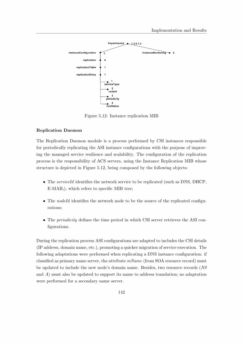
Implementation and Results
Figure 5.12: Instance replication MIB
Replication Daemon
The Replication Daemon module is a process performed by CSI instances responsible
for periodically replicating the ASI instance configurations with the purpose of improv-
ing the managed service resilience and scalability. The configuration of the replication
process is the responsibility of ACS servers, using the Instance Replication MIB whose
structure is depicted in Figure 5.12, being composed by the following objects:
• The serviceId identifies the network service to be replicated (such as DNS, DHCP,
E-MAIL), which refers to specific MIB tree;
• The nodeId identifies the network node to be the source of the replicated configu-
rations;
• The periodicity defines the time period in which CSI server retrieves the ASI con-
figurations.
During the replication process ASI configurations are adapted to includes the CSI details
(IP address, domain name, etc.), promoting a quicker migration of service execution. The
following adaptations were performed when replicating a DNS instance configuration: if
classified as primary name server, the attributemName (from SOA resource record) must
be updated to include the new node’s domain name. Besides, two resource records (NS
and A) must also be updated to support its name to address translation; no adaptation
were performed for a secondary name server.
142

Implementation and Results
Instance Management
The Instance Management module was implemented using SNMP4j API, it includes the
implementation of the management objects defined by the DNS instance management
information model.
Instance Classification Management
The Instance Classification Management module works in cooperation with the Instance
Management module to enable the management of instance classification: initiating
the service execution when new instance configurations are defined; stoping the service
execution when all instance configurations are erased; and restarting the service exe-
cution when configurations are changes. When no instance configurations are defined,
the Instance Classification Management module enables the replication procedure by
activating the corresponding Replication Daemon.
Service Instrumentation
The Service Instrumentation module is divided into two parts: the first part that includes
a interface common to heterogeneous service instance implementations; the second part
that includes the instrumentation required for the management effectiveness of first part.
The first part includes the following group of independent configuration management
methods:
• Get, to retrieve all or a part of the service instance configurations;
• Set, to define new service instance configurations;
• Add, to add a new configuration element to an already existing service instance
configuration;
• Put, to update an existing configuration element;
• Delete to delete all or part of the service instance configurations.
The implementation of the previous methods for different implementations represents
the second part of the module. In this prototype they were implemented for three vendor
specific DNS implementations.
143

Implementation and Results
5.5 Experiments
In this section the author demonstrates MiNSC’s most important functionalities through
the presentation of the results of a small set of experiments for the DNS service configu-
ration management. The most important goals of this section include the demonstration
of:
• MiNSC’s capability to overcome the use of management translations when sup-
porting the integrated management of heterogeneous DNS implementations;
• MiNSC’s management simplification supported by universal configurations de-
ployed on heterogeneous DNS implementations;
• MiNSC’s capability to perform an automatic (and secure) deployment of a DNS
domain configuration based on the meta-configurations administratively defined;
• MiNSC’s capability to enhance resilience and scalability of the managed DNS ser-
vice.
SMON plays a key role by notifying the configuration management server as to the need
to enact configuration management procedures. However, this enaction of SMON falls
out of the scope of this thesis, so the notification interaction was manually triggered.
5.5.1 DNS Instance Configuration
The number of DNS instances used depends on the redundancy distribution level pre-
tended for the management context. Based on the DNS meta-configurations defined, the
administrator is able to distribute instance classification as required. Using three DNS
implementations and three levels of redundancy distribution, the following deployment
patterns may be found:
• When the DNS service is deployed with a high-level of redundancy distribution only
one DNS instance is classified as ASI (the remaining two are classified as CSI). The
following configurations are deployed for the primary name server and include: the
definition of a DNS Zone identified as scm.di.uminho.pt ; a SOA resource record;
disabled caching, notification and recursion mechanisms.
144
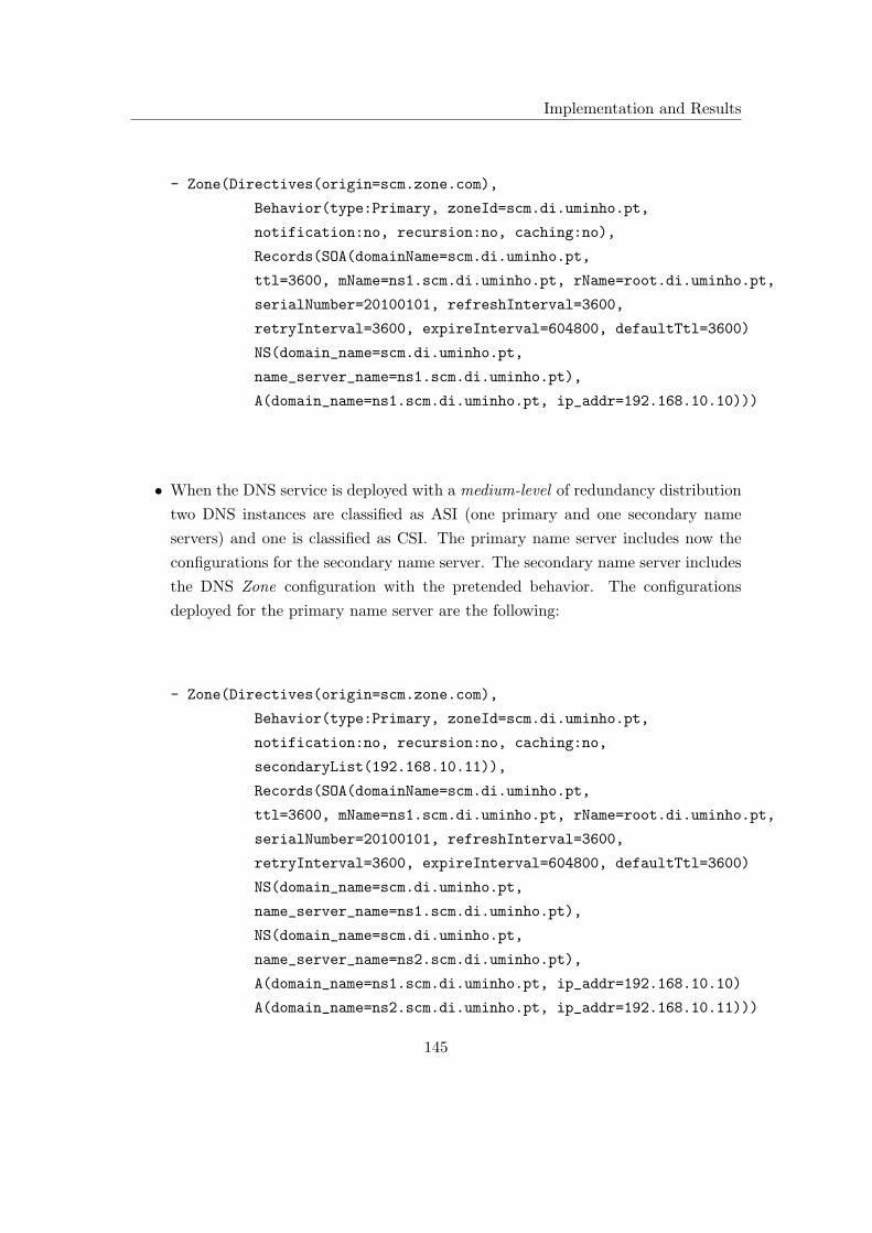
Implementation and Results
- Zone(Directives(origin=scm.zone.com),
Behavior(type:Primary, zoneId=scm.di.uminho.pt,
notification:no, recursion:no, caching:no),
Records(SOA(domainName=scm.di.uminho.pt,
ttl=3600, mName=ns1.scm.di.uminho.pt, rName=root.di.uminho.pt,
serialNumber=20100101, refreshInterval=3600,
retryInterval=3600, expireInterval=604800, defaultTtl=3600)
NS(domain_name=scm.di.uminho.pt,
name_server_name=ns1.scm.di.uminho.pt),
A(domain_name=ns1.scm.di.uminho.pt, ip_addr=192.168.10.10)))
• When the DNS service is deployed with a medium-level of redundancy distribution
two DNS instances are classified as ASI (one primary and one secondary name
servers) and one is classified as CSI. The primary name server includes now the
configurations for the secondary name server. The secondary name server includes
the DNS Zone configuration with the pretended behavior. The configurations
deployed for the primary name server are the following:
- Zone(Directives(origin=scm.zone.com),
Behavior(type:Primary, zoneId=scm.di.uminho.pt,
notification:no, recursion:no, caching:no,
secondaryList(192.168.10.11)),
Records(SOA(domainName=scm.di.uminho.pt,
ttl=3600, mName=ns1.scm.di.uminho.pt, rName=root.di.uminho.pt,
serialNumber=20100101, refreshInterval=3600,
retryInterval=3600, expireInterval=604800, defaultTtl=3600)
NS(domain_name=scm.di.uminho.pt,
name_server_name=ns1.scm.di.uminho.pt),
NS(domain_name=scm.di.uminho.pt,
name_server_name=ns2.scm.di.uminho.pt),
A(domain_name=ns1.scm.di.uminho.pt, ip_addr=192.168.10.10)
A(domain_name=ns2.scm.di.uminho.pt, ip_addr=192.168.10.11)))
145
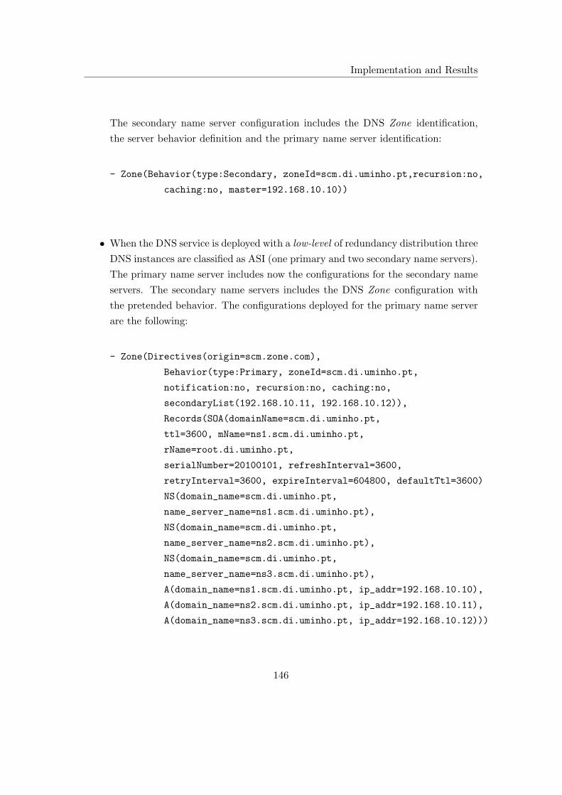
Implementation and Results
The secondary name server configuration includes the DNS Zone identification,
the server behavior definition and the primary name server identification:
- Zone(Behavior(type:Secondary, zoneId=scm.di.uminho.pt,recursion:no,
caching:no, master=192.168.10.10))
• When the DNS service is deployed with a low-level of redundancy distribution three
DNS instances are classified as ASI (one primary and two secondary name servers).
The primary name server includes now the configurations for the secondary name
servers. The secondary name servers includes the DNS Zone configuration with
the pretended behavior. The configurations deployed for the primary name server
are the following:
- Zone(Directives(origin=scm.zone.com),
Behavior(type:Primary, zoneId=scm.di.uminho.pt,
notification:no, recursion:no, caching:no,
secondaryList(192.168.10.11, 192.168.10.12)),
Records(SOA(domainName=scm.di.uminho.pt,
ttl=3600, mName=ns1.scm.di.uminho.pt,
rName=root.di.uminho.pt,
serialNumber=20100101, refreshInterval=3600,
retryInterval=3600, expireInterval=604800, defaultTtl=3600)
NS(domain_name=scm.di.uminho.pt,
name_server_name=ns1.scm.di.uminho.pt),
NS(domain_name=scm.di.uminho.pt,
name_server_name=ns2.scm.di.uminho.pt),
NS(domain_name=scm.di.uminho.pt,
name_server_name=ns3.scm.di.uminho.pt),
A(domain_name=ns1.scm.di.uminho.pt, ip_addr=192.168.10.10),
A(domain_name=ns2.scm.di.uminho.pt, ip_addr=192.168.10.11),
A(domain_name=ns3.scm.di.uminho.pt, ip_addr=192.168.10.12)))
146

Implementation and Results
The secondary name server configuration includes the DNS Zone identification,
the server behavior definition and the primary name server identification:
- Zone(Behavior(type:Secondary, zoneId=scm.di.uminho.pt,recursion:no,
caching:no, master=192.168.10.10))
5.5.2 DNS Management Evaluation
A complementary analysis was conducted as to evaluate MiNSC’s effectiveness for DNS
management compared to popular DNS management tools such as Probind [243], unxs-
Bind [244] and Roster [245]. This study was divided into three parts: the first part
evaluated the DNS management from the network operation perspective; the second
part evaluated the provisioning of most basic DNS management functionalities; the
third part evaluated the provisioning of advanced management functionalities. These
results are depicted in Table 5.1 and the most important conclusions drawn from them
include:
• From the network operation perspective, all DNS management framework’s per-
form similarly. MiNSC supports communication reliability, communicating parties
authentication and privacy through the implementation of SNMPv3 over TCP,
using CBC-DES Symmetric Encryption Protocol for confidentiality and HMAC-
MD5-96 for authentication. Probind uses the reliability of the Rsync mechanism
over secure SSH to synchronize server files and manage DNS server configurations.
UnxsBind uses the MySQL database replication mechanism to synchronize the
DNS server configurations, thus supporting communication reliability, privacy and
user authentication. Roster uses a Secure Sockets Layer (SSL) enabled XML-RPC
protocol for the distributed DNS servers configuration, also supporting client au-
thentication based on Lightweight Directory Access Protocol (LDAP) and others;
• From the simple functionalities perspective, all framework’s provide similar capa-
bilities even though there exists MiNSC’s inability to manage non-standard func-
tionalities (such as Bind’s serial-query-rate). So, all frameworks enable the man-
agement of most basic functionalities. These includes multi-server management,
server role management (primary/secondary), resource records and options man-
agement, including the definition of caching type, notifications, recursion, among
other mechanism;
147

Implementation and Results
Table 5.1: DNS management tools features evaluation
Functionality MiNSC Probind unxsBind Roster
Network Operation
Privacy 3 3 3 3
Authentication 3 3 3 3
Reliability 3 3 3 3
Simple Functionalities
Configuration Validation 7 7 7 3
Master/Slave Management 3 3 3 3
Multi-Server Management 3 3 3 3
Options Management 3 3 3 3
Resource Record Management 3 3 3 3
Zone Management 3 3 3 3
Proprietary Functionalities 7 3 3 3
Advanced Functionalities
Interoperability 3 7 7 7
Scalability 3 7 7 7
Resilience 3 7 7 7
Heterogeneity 3 7 7 7
Automation 7 7 7 7
• Advanced functionalities are necessary for a management framework’s capability
to support a larger scale, heterogeneous DNS management environment where
concepts such as automation, interoperability, scalability and resilience are funda-
mental to the effectiveness of DNS management applications. With the exception
of MiNSC, all frameworks fail to provide an adequate response to these advanced
requirements due to the following reasons: most frameworks do not improve scal-
ability or resilience, because they are mostly dependent on centralized entities;
they do not support integrated DNS management, supporting only the most pop-
ular implementations; they do not support the automation due to the fact that
they are based on low-level mechanisms, dependent on the administrator’s manual
intervention to derive and enforce management decisions; do not promote interop-
erability, using proprietary interfaces. At this level, MiNSC also does not imple-
ment a highly automated DNS management solution (even though it provides some
148

Implementation and Results
degree of management automation), but it supports the integrated DNS manage-
ment (without applying intermediary management translations). Furthermore it
is based on a distributed, two-layer architecture, improving the DNS management
scalability, resilience and maintaining high-level of interoperability (to higher level
management applications), through the implementation of a standard interface;
• Based on this evaluation its clear that most common DNS management applica-
tions, commercially available, provide similar alternatives at the level of network
operation and most simple functionalities. They support secure and reliable config-
uration management of multiple servers, DNS zones and other basic functionalities.
On the other hand, they fail to include advanced management functionalities, such
as, integrated management, automation and resilience improvement methods.
5.5.3 DNS Instance Configuration Replication
The DNS instance configuration replication was the first experimental procedure per-
formed with MiNSC’s prototype whose results were published in [46]. In this experiment,
a configuration management server was used to replicate the DNS instance static con-
figurations between heterogeneous implementations. The main goals were to:
• Demonstrate the effectiveness of the DNS instance management information model
by enabling the management of standard DNS functionalities;
• Demonstrate MiNSC’s Network Service Instance Management layer unification
by enforcing independent configurations on heterogeneous DNS implementations,
without using management translation mechanisms.
The experimental scenario is depicted in Figure 5.13 where two DNS instances were
used, one serving as the source of configurations and the other as destination. For this
experiment three DNS implementations were used, namely Bind9 for Linux (Ubuntu)
and MS Windows and Posadis also for MS Windows. It is important to note that only
the instance’s static configurations were replicated.
The source DNS instance was configured with two DNS Zones: abc.zone.com, where
the instance behaves as a primary name sever; and xyz.zone.com, where the instance
behaves as a secondary name server. The complete set of configurations used for the
DNS instance includes the following:
149

Implementation and Results
- Zone(Directives(origin=abc.zone.com), Behavior(type:Primary,
zoneId=abc.zone.com, notification:no, recursion:no, caching:no,
secondaryList(192.168.10.9; 192.168.10.10)),
Records(SOA(domainName=abc.zone.com, ttl=3600,
mName=ns.abc.zone.com, rName=root.abc.zone.com,
serialNumber=20100101, refreshInterval=3600, retryInterval=3600,
expireInterval=604800, defaultTtl=3600),
NS(domainName=abc.zone.com, nameServerName=ns.abc.zone.com),
NS(domainName=abc.zone.com, nameServerName=ns0.abc.zone.com),
NS(domainName=abc.zone.com, nameServerName=ns1.abc.zone.com),
A(domainName=ns.abc.zone.com, ipAddr=192.168.10.8),
A(domainName=ns0.abc.zone.com, ipAddr=192.168.10.9),
A(domainName=ns1.abc.zone.com, ipAddr=192.168.10.10)))
- Zone(Behavior(type:Secondary, zoneId=xyz.zone.com, recursion:no,
caching:no, master=192.168.10.11))
The first Zone, identified as abc.zone.com, includes the definition of the standard direc-
tives, the Zone’s behavior (defining the name server role as well as other standard DNS
mechanisms) and seven resource records identifying the Zone’s name servers (not in-
cluded in the presented excerpt). The second Zone, identified as xyz.zone.com, includes
Figure 5.13: DNS instance configuration replication
150
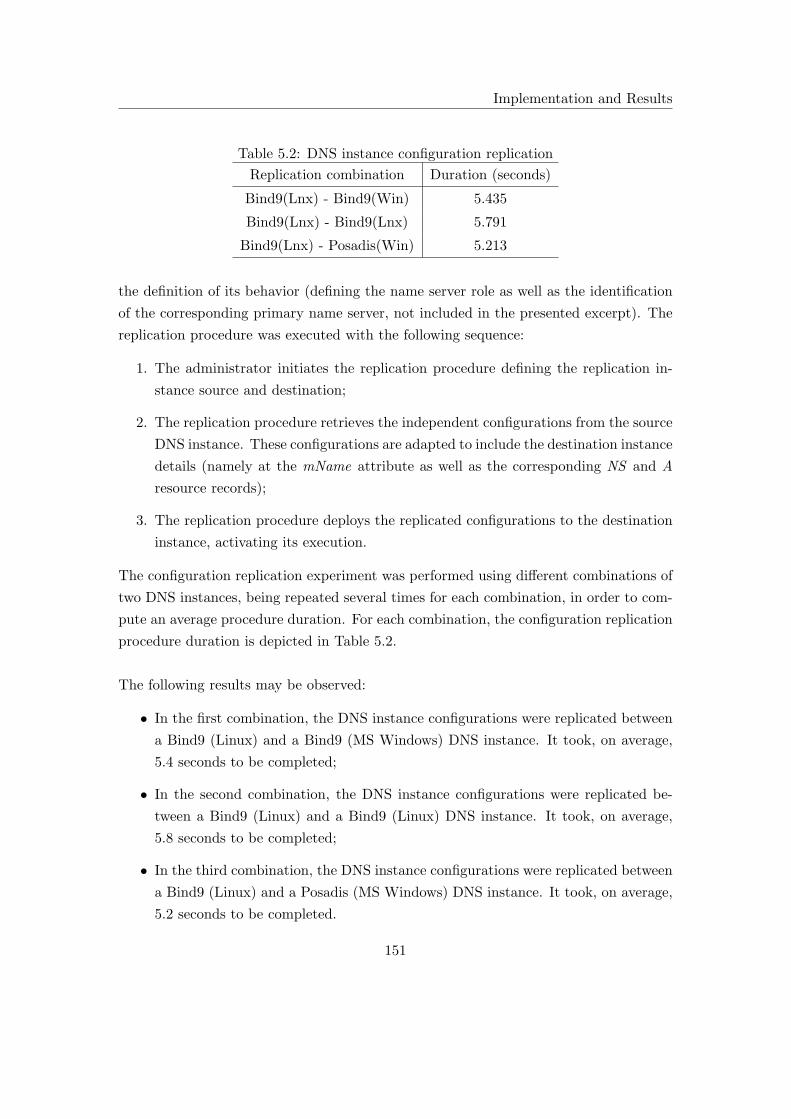
Implementation and Results
Table 5.2: DNS instance configuration replication
Replication combination Duration (seconds)
Bind9(Lnx) - Bind9(Win) 5.435
Bind9(Lnx) - Bind9(Lnx) 5.791
Bind9(Lnx) - Posadis(Win) 5.213
the definition of its behavior (defining the name server role as well as the identification
of the corresponding primary name server, not included in the presented excerpt). The
replication procedure was executed with the following sequence:
1. The administrator initiates the replication procedure defining the replication in-
stance source and destination;
2. The replication procedure retrieves the independent configurations from the source
DNS instance. These configurations are adapted to include the destination instance
details (namely at the mName attribute as well as the corresponding NS and A
resource records);
3. The replication procedure deploys the replicated configurations to the destination
instance, activating its execution.
The configuration replication experiment was performed using different combinations of
two DNS instances, being repeated several times for each combination, in order to com-
pute an average procedure duration. For each combination, the configuration replication
procedure duration is depicted in Table 5.2.
The following results may be observed:
• In the first combination, the DNS instance configurations were replicated between
a Bind9 (Linux) and a Bind9 (MS Windows) DNS instance. It took, on average,
5.4 seconds to be completed;
• In the second combination, the DNS instance configurations were replicated be-
tween a Bind9 (Linux) and a Bind9 (Linux) DNS instance. It took, on average,
5.8 seconds to be completed;
• In the third combination, the DNS instance configurations were replicated between
a Bind9 (Linux) and a Posadis (MS Windows) DNS instance. It took, on average,
5.2 seconds to be completed.
151

Implementation and Results
The most important conclusions taken from this experiment can be summarized as fol-
lows:
• The DNS instance management information model proposed, enables the configu-
ration management of standard DNS functionalities (such as DNS Zones, as well
as caching, recursion and notification mechanisms), on heterogeneous implemen-
tations, only requiring the development of an MIB instrumentation;
• The DNS instance configuration replication procedure took, on average, 5.5 seconds
to retrieve the static configurations from a source DNS instance, deactivate its
service execution, modify the configuration to include the destination instance
details, deploy and activate those configurations at the destination DNS instance.
This process was completed regardless of the instances implementations, without
using management translation mechanisms. This demonstrates the management
unification provided by MiNSC’s Network Service Instance Management layer.
5.5.4 DNS Service Deployment
In this experiment, both MiNSC’s management layers were used to perform the auto-
matic setup of a DNS domain. The DNS service meta-configurations were administra-
tively defined at the Service Management layer, enabling the automatic generation of the
DNS instances configurations at the Network Service Instance Management layer. The
DNS service deployment scenario is depicted in Figure 5.14, being composed by three
DNS instances, where the configurations are deployed, and one configuration server
(ACS) where the DNS meta-configurations are defined. With this experiment the fol-
lowing objectives were persued:
• To create a mid-level mechanism that simplifies the DNS service management,
namely supporting the automatic setup of a DNS domain, referred to as DNS
service deployment;
• To demonstrate the effectiveness of MiNSC’s Service Management layer by auto-
matically computing the DNS instance configurations based on the DNS meta-
configurations;
• To demonstrate the framework’s autonomy by modifying the DNS service deploy-
ment resource support (using various DNS instances implementation).
152

Implementation and Results
The following DNS service meta-configurations were used:
- Domain(parent:di.uminho.pt, authority:scm)
- Operation(redundancy-distribution:low, recursion=no, notification:no,
caching:no, volatility:low, persistence:low, validity:low, duration:low)
A DNS domain called scm.di.uminho.pt was created with no Elements defined. The
service behavior, defined by the Operation meta-configuration, included: a low-level of
redundancy distribution, ensuring that all DNS instances available were classified as ASI
(one primary and two secondary name servers); a low value for volatility, persistence,
validity and duration that were mapped into DNS instance configurations like TTL,
Refresh, Retry and Expire (using DNS Parameters MIB); no value for deactivation
of standard DNS functionalities namely notification, caching and recursion. The DNS
service deployment was performed with the following sequence:
1. The administrator submitted the DNS service meta-configurations to the ACS
server using the MIB interface;
Figure 5.14: DNS service deployment
153

Implementation and Results
Table 5.3: DNS service deployment
Deployment Pattern Duration (seconds)
A-A-A 4.035
A-A-B 3.919
A-B-B 3.469
A-B-C 3.558
A-A-C 3.908
A-C-C 3.471
B-B-B 3.017
B-B-C 3.005
B-C-C 3.340
C-C-C 3.154
2. The ACS server used the DNS service meta-configuration to derive the DNS in-
stance configurations. The primary name server configuration was deployed using
the ASI’s MIB;
3. The configurations for the first secondary name server instance were deployed using
the CSI’s MIB;
4. The configurations for the second secondary name server were also deployed using
the CSI’s MIB.
The configurations deployed for the primary and secondary name servers can be found
in the previous section, when the DNS service is deployed with a low-level of redundancy
distribution. To demonstrate MiNSC’s management independence three different DNS
implementations were used, creating different deployment patterns: a Bind9 implemen-
tation for Linux (refereed to as A) and MS Windows (referred to as B) and a Posadis
implementation for MS Windows (referred to as C ). The DNS service was deployed us-
ing different combinations of three implementations and the average procedure duration
(each deployment procedure was repeated several times) is depicted in Table 5.3. The
most important conclusions taken from this experiment can be summarized as follows:
• The deployment procedure demonstrates MiNSC’s capability to automatically setup
a DNS domain based on a group of meta-configurations. This procedure simplifies
the administrator’s task by automating a traditionally manual operation, improves
154

Implementation and Results
management efficiency by reducing typographic errors and enables quick (and se-
cure) setup of a network service;
• The deployment process is almost completely autonomous in terms of instance
heterogeneity, which demonstrates the framework’s independence regarding service
implementations. This is important because management translations aren’t used
and the administrator doesn’t need to understand all the implementations detail;
• The DNS service deployment process took, on average, 3.5 seconds to be completed.
The time taken includes the configuration calculation and their secure and reliable
deployment, using SNMPv3 with notification confirmation, for three servers (one
primary and two secondary). So, this prototype takes, on average, a little more
than 1 second to deploy a Zone configuration in a DNS instance.
5.5.5 DNS Instance Execution Migration
MiNSC’s Network Service Instance Management layer provides the management univer-
sality, which enables the management of heterogeneous network service instances regard-
less of their implementations details. Such unification provides simplicity by overcoming
the use of management translations. The realization of more advanced operations is also
enabled, such as the migration of a network service instance execution, based on the
automatic replication of configurations with the following purpose:
• To improve service scalability by increasing the number of network service in-
stances defined for a service deployment. With the ASI instance configurations
automatically and periodically replicated to CSI instances, a new ASI is created
by activating part of those configurations at the CSI. So, this procedure increases
the number of ASI instances defined by a service deployment through the load-
balancing of configurations replicated from a ASI to a CSI, which extends the
network service resource support. This procedure is referred to as a service in-
stance expansion;
• To improve the service resilience (to instance failures or performance degradation),
migrating the service execution from a faulty ASI instance to a CSI instance us-
ing the ASI instance configurations previously replicated. When an ASI instance
fails (detected by the monitoring system), the ACS server deactivates the service
execution at the faulty instance (if possible) and activates the service execution at
the CSI instance using the replicated configurations, automatically replacing the
faulty instance with minimum data losses.
155
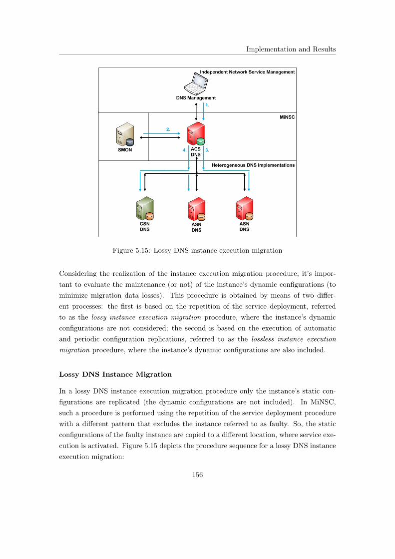
Implementation and Results
Figure 5.15: Lossy DNS instance execution migration
Considering the realization of the instance execution migration procedure, it’s impor-
tant to evaluate the maintenance (or not) of the instance’s dynamic configurations (to
minimize migration data losses). This procedure is obtained by means of two differ-
ent processes: the first is based on the repetition of the service deployment, referred
to as the lossy instance execution migration procedure, where the instance’s dynamic
configurations are not considered; the second is based on the execution of automatic
and periodic configuration replications, referred to as the lossless instance execution
migration procedure, where the instance’s dynamic configurations are also included.
Lossy DNS Instance Migration
In a lossy DNS instance execution migration procedure only the instance’s static con-
figurations are replicated (the dynamic configurations are not included). In MiNSC,
such a procedure is performed using the repetition of the service deployment procedure
with a different pattern that excludes the instance referred to as faulty. So, the static
configurations of the faulty instance are copied to a different location, where service exe-
cution is activated. Figure 5.15 depicts the procedure sequence for a lossy DNS instance
execution migration:
156

Implementation and Results
Table 5.4: Lossy DNS instance execution migration
Deployment (seconds) Fault Migration (seconds)
Undeploy Deployment Total
Low Redundancy Distribution
2.884 P 4.775 1.724 6.515
2.882 S 5.174 1.835 7.016
3.220 S 4.841 1.919 6.787
Medium Redundancy Distribution
2.205 P 3.346 1.689 5.041
2.090 S 3.590 1.851 5.448
High Redundancy Distribution
1.213 P 1.533 0.970 2.515
1. The DNS service is deployed over three DNS implementations using different redun-
dancy distribution levels based on administratively defined DNS meta-configurations;
2. The monitoring system (SMON) notifies the configuration server (ACS) about the
need to perform a lossy instance execution migration due to a faulty DNS instance;
3. The configuration server deactivates the service execution at the faulty DNS in-
stance, which is proceeded by the realization of a new DNS deployment (consid-
ering the remaining instances) based on the DNS meta-configurations previously
defined;
4. The service instance configurations are generated and deployed, embedding the
configurations of the faulty instance.
The MiNSC based prototype was used to test a lossy DNS instance execution migration
and the results are depicted in Table 5.4. It’s important to note that the monitoring
information was manually generated, simulating a DNS instance failure. Three different
service deployments were used to experiment this procedure, corresponding to the levels
of redundancy distribution defined.
When the DNS service was deployed with a low-level of redundancy distribution,
all instances were classified as ASI (one primary and two secondary name servers). Af-
ter the migration procedures, only two ASI instances remain active (one primary and
one secondary name servers). From Table 5.4, it can be verified that the DNS ser-
vice deployment over three DNS instances took, on average, 3 seconds to be completed;
157

Implementation and Results
when an error occurred in a DNS instance it took, on average, 4.9 seconds to unde-
ploy the previously deployed configurations (involving the deactivation of three instance
configurations); then, it required, on average, 1.8 seconds to redeploy the DNS service
configurations for the two remaining nodes. On average it took 6.8 seconds to migrate a
DNS instance configuration, applying a lossy procedure, after receiving the monitoring
notification. The same procedure was repeated for medium and high-level of redundancy
distribution and obtained, on average, a duration of 5.3 and 2.5 seconds respectively.
Some important conclusions could be taken from this experiment:
• Using a lossy DNS instance execution migration procedure is possible to improve
DNS resilience by transferring the service execution, when a failure is detected,
based on the instance’s static configurations. This is performed by redeploying the
DNS configurations, excluding the faulty instance, automatically re-distributing
the configurations for the remaining instances. The monitoring system contribu-
tion is essential for this procedure;
• Since the lossy DNS instance execution migration procedure does not considers
the instance’s dynamic configurations, data losses are found which may cause dis-
ruptions in the service execution;
• The migration process is highly dependent on the number of ASI instances avail-
able. As the number of instances increases, the longer time it takes to migrate a
service instance since the service must be undeployed and redeployed for a larger
number of instances;
• For this prototype the procedure of migrating a faulty instance took, on aver-
age, approximately double of the time taken to initially deploy DNS instance’s
configurations. This is explained by the necessity of undeploy previously deployed
configurations (which takes approximately the same time as their deployment) and
redeploy new configurations on a lower number of instances;
• Such migration procedure is performed automatically, regardless of the instances
details, without using management translations. This proposal represents an im-
portant gain to DNS resilience, not found in any other management framework,
that commonly implement manual-based procedures for a limited set of instance
implementations.
158

Implementation and Results
Figure 5.16: Lossless DNS instance execution migration
Lossless DNS Instance Migration
Also with the purpose of improving the DNS resilience to instance failures, a lossless
DNS instance execution migration procedure was specified aiming to preserve the in-
stance’s static and dynamic configurations, in opposition to the previous proposal. To
this matter the lossless migration procedure ensures that, in the event of service instance
failure, configurations are previously replicated in a redundant element, thus enabling
a seamless service execution transfer without effective data losses. Such a functionality
was implemented in the MiNSC prototype and experimented for the DNS management
test bed.
The sequence for the realization of the lossless DNS instance execution migration pro-
cedure is depicted in Figure 5.16 and includes the following steps:
1. The DNS service is deployed over three DNS implementations using different redun-
dancy distribution levels based on administratively defined DNS meta-configurations;
2. When the DNS service configuration is deployed, the CSI nodes are configured to
automatically and periodically replicate the ASI static and dynamic configurations.
159
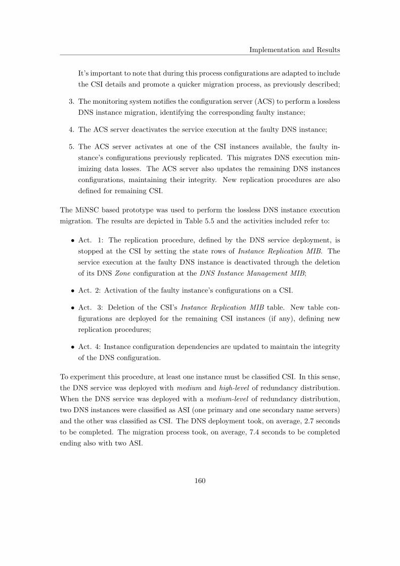
Implementation and Results
It’s important to note that during this process configurations are adapted to include
the CSI details and promote a quicker migration process, as previously described;
3. The monitoring system notifies the configuration server (ACS) to perform a lossless
DNS instance migration, identifying the corresponding faulty instance;
4. The ACS server deactivates the service execution at the faulty DNS instance;
5. The ACS server activates at one of the CSI instances available, the faulty in-
stance’s configurations previously replicated. This migrates DNS execution min-
imizing data losses. The ACS server also updates the remaining DNS instances
configurations, maintaining their integrity. New replication procedures are also
defined for remaining CSI.
The MiNSC based prototype was used to perform the lossless DNS instance execution
migration. The results are depicted in Table 5.5 and the activities included refer to:
• Act. 1: The replication procedure, defined by the DNS service deployment, is
stopped at the CSI by setting the state rows of Instance Replication MIB. The
service execution at the faulty DNS instance is deactivated through the deletion
of its DNS Zone configuration at the DNS Instance Management MIB;
• Act. 2: Activation of the faulty instance’s configurations on a CSI.
• Act. 3: Deletion of the CSI’s Instance Replication MIB table. New table con-
figurations are deployed for the remaining CSI instances (if any), defining new
replication procedures;
• Act. 4: Instance configuration dependencies are updated to maintain the integrity
of the DNS configuration.
To experiment this procedure, at least one instance must be classified CSI. In this sense,
the DNS service was deployed with medium and high-level of redundancy distribution.
When the DNS service was deployed with a medium-level of redundancy distribution,
two DNS instances were classified as ASI (one primary and one secondary name servers)
and the other was classified as CSI. The DNS deployment took, on average, 2.7 seconds
to be completed. The migration process took, on average, 7.4 seconds to be completed
ending also with two ASI.
160

Implementation and Results
Table 5.5: Lossless DNS instance execution migration
Deployment (seconds) Fault Migration (seconds)
Act. 1 Act. 2 Act. 3 Act. 4 Duration
Medium Redundancy Distribution
2.827 P 2.028 1.502 2.663 1.210 7.407
2.657 S 1.733 1.533 2.628 1.494 7.392
High Redundancy Distribution
1.660 P 2.009 1.438 2.979 0 6.431
When the DNS service was deployed with a high-level of redundancy distribution,
one DNS instance was classified as ASI (primary name server) while the remaining two
instances were classified as CSI. The DNS deployment took, on average, 1.7 seconds
to be completed. The migration process tool, on average, 6.4 seconds to be completed
ending also with one ASI. Since the primary name server has no dependencies no time
was required to update dependencies.
It was concluded that:
• When the DNS was deployed with a medium-level of redundancy distribution it
took, on average, approximately three times the DNS deployment duration to
migrate a instance execution. When the DNS was deployed with a high-level of
redundancy distribution it took, on average, approximately four times the DNS
deployment duration to migrate a instance execution.
This difference is mainly found due to the short deployment duration taken for a
high-level of redundancy distribution, while most remaining migration activities
duration were maintained for both levels. This results in a higher time relation for
a high-level of redundancy distribution;
• To perform a lossless DNS instance execution migration at least one candidate
instance must exist to execute the configuration’s replication;
• Based on the CSI configuration replication procedure, it was possible to transfer
the DNS service execution to a different instance without data losses, regardless
of implementations details. This procedure improves DNS resilience to instance
failures;
161

Implementation and Results
• In this experiment only the DNS instance’s static configurations were migrated.
To avoid cache poisoning attack, DNS instances commonly block external updates
to their cache, so dynamic configuration were not replicated.
Comparing the realization of a lossy and a lossless DNS instance execution migration
procedure the following conclusion were taken:
• The lossless DNS instance execution migration procedure can only be performed
when candidate instances are defined. The lossy DNS instance execution migration
procedure can be performed regardless of existence of candidate instances, in their
absence it reduces the number of active instances;
• Both procedures improve the DNS resilience to instance failures. For the lossless
DNS instance migration procedure a candidate instance is used to directly replace
a faulty instance while in the lossy DNS instance migration procedure the service
deployment is repeated to change the deployment pattern (replacing the faulty
instance by a candidate or by concentrating in a lower number of instances);
• The redeployment of DNS configuration requires temporary service suspension
while the lossless DNS instance migration procedure only individual instance tem-
porary suspension is required;
• For the presented prototype the lossless DNS instance migration procedure takes
more time to be completed than the lossy DNS instance migration procedure. The
additional time took by the lossless DNS instance migration procedure was due to
the additional procedures performed such as the management of replication tables
and configuration dependencies update;
• The procedure duration difference for both alternatives is not significative for an
automated process that overcome the limitation inherent of a manual procedure;
• The realization of both procedures duration depend on the number of network
service instances, their classification and configurations defined.
5.5.6 DNS Instance Expansion
The DNS instance expansion is a complementary functionality that increases the number
of ASI instances in response to scalability limitations (due to resource constraint). Based
on the execution of periodic instance configuration replication procedures DNS instances
162

Implementation and Results
Figure 5.17: DNS instance expansion
may be extended, transforming CSI into ASI instances. The DNS instance expansion
procedure is depicted in Figure 5.17 and includes the following steps:
1. Two DNS Zones are deployed (scm.di.uminho.pt and scm1.di.uminho.pt) over
three DNS instances using high and medium-levels of redundancy distribution;
2. The instances classified as CSI are responsible for the periodic replication of ASI
configurations;
3. The monitoring system notifies the ACS server about the need to perform a DNS
instance expansion, identifying the instance to perform load-balancing;
4. The ACS server deactivates part of the faulty ASI’s configurations. In this exper-
iment, 50% of the ASI’s configurations were deactivated, which means that the
Zone identified by scm1.di.uminho.pt was suspended;
5. The DNS Zone suspended at the ASI is activated at the CSI, using the previously
replicated configurations. This extends the DNS service resources to include a new
ASI;
163

Implementation and Results
Table 5.6: DNS instance expansion
Fault Expansion (seconds)
Act. 1 Act. 2 Act. 3 Act. 4 Duration
Medium Redundancy Distribution
P 2.613 1.842 5.660 2.240 12.359
S 1.903 1.714 5.388 3.267 12.278
High Redundancy Distribution
P 2.553 1.644 5.992 0.934 11.125
6. Unchanged instance configurations are updated to include the new ASI. Remaining
CSI replication tables are updated.
Using MiNSC’s prototype, the DNS instance expansion procedure was experimented
and the results obtained are summarized in Table 5.6. The activities referred in the
table are the same as those from the previous experiment. At least one DNS instance
must be classified as CSI, so DNS service was deployed with medium and high-level of
redundancy distribution. When the DNS service was deployed with a medium-level of
redundancy distribution, the procedure to expand a DNS instance took, on average,
12.4 seconds (considering a primary name server for load-balancing) and 12.3 seconds
(considering a secondary name sever for load-balancing) to be completed. The difference
between procedures duration is considered irrelevant and happened due to the fact that
primary name servers have a larger amount of configurations to be managed. When the
DNS service was deployed with a high-level of redundancy distribution, the procedure
to expand a DNS instance took, on average, 11.1 seconds to be completed.
The following conclusions were taken from the experiments:
• With MiNSC’s instance expansion mechanism the ASI’s configurations can be
balanced (for a given percentage) to a CSI, creating a new ASI. This improves
DNS scalability by increasing the number of resources available;
• The DNS service was securely and automatically extended in a few tenths of sec-
onds. If it were to be performed manually, would take several minutes and would
be prone to manual errors;
• The implementation of such a mechanism promotes a more efficient resource man-
agement, increasing the number of service instances as required;
164

Implementation and Results
• Future developments include the realization of a complementary mechanism aiming
to concentrate configurations, decreasing the number of resources used.
5.6 Conclusion
This chapter explores the practical details associated with the implementation of a
MiNSC based prototype for DNS management. In the beginning of the chapter, the
structure of the prototype elements was described including the modules implemented
and algorithms applied. Then, the two-layer DNS management information model was
described, including their formal representation in a MIB tree. The final part of the
chapter was used to describe the experiments made, focusing on demonstrating feasi-
bility and effectiveness of MiNSC capabilities for DNS management. The experiments
involved the cooperation of the Service Management and Network Service Instance Man-
agement layers to enable the integrated DNS management.
From the group of experiments made it was possible to confirm the universality of
the DNS management data model proposed, enabling the management of heterogeneous
implementations with negligible differences. The DNS deployment was experimented
for the automatic setup of a DNS domain. In a few seconds, a DNS domain composed
by three servers was automatically and securely created. The DNS instance expansion
increased the number of DNS instances based on load-balancing of configurations, using
candidate instances, to improve DNS service performance and scalability. Even though
this procedure requires the over-provisioning of DNS instances, it enables a more efficient
resource management, assigning instances as their are required.
The DNS instance execution migration used candidate instances to improve DNS
resilience to instance failures. Whatever the migration alternative used, a faulty (active)
instance is automatically replaced by a candidate (which becomes active) is a few tens
of seconds. The most important differences between the alternatives presented are the
maintenance of the faulty instance’s dynamic configurations and the necessity of candi-
date instances, which incurs into additional resources. To conclude, the results clearly
demonstrate the effectiveness of MiNSC’s service management functionalities when ap-
plied to a practical management example.
165

166

Chapter 6
Evaluation
After exploring MiNSC’s details, including results from a prototype experiment, it is
important that its contribution within the context of contemporary network manage-
ment frameworks be evaluated. As such, this section provides a theoretical evaluation
comparing relevant integrated network management frameworks with MiNSC’s proposal.
From the evaluation results, the author concludes that MiNSC does not aim to replace
any of the evaluated frameworks. Instead, it can be used as a alternative for the im-
plementation of management translations, whose limitations were previously identified,
while potentiating resilience, scalability and interoperability of the network management
service and of the managed services.
6.1 Motivation
Contemporary network management frameworks which aim to support heterogeneous
network elements use management translations [42] to effectively enforce independent
management representations (such as policies) into management interfaces and data
models. However, the implementation of management translations represents a com-
plex task, hard to be fulfilled in large scale heterogeneous networks, which, when allied
to other limitations, make the availability of such proposals very scarce. MiNSC cre-
ates a complementary alternative for the configuration management unification of het-
erogeneous network service implementations. These not only overcome the limitations
inherent to the management translations but contain additional concerns regarding ser-
vice resilience, scalability, interoperability and management simplification as well. This
chapter evaluates MiNSC’s contribution in comparison to well known integrated network
management frameworks such as FOCALE and WBEM.
167

Evaluation
FOCALE is a distributed architecture for orchestrating the behavior of heteroge-
neous network elements based on semantically rich representations with a high orienta-
tion towards business goals. FOCALE implements the autonomic network management
control loop by automatically adjusting the network element’s behavior in accordance
with administratively defined business policies. Those policies are refined by autonomic
managers and applied to autonomic network elements that ensure their effectiveness.
In case of non-autonomic network elements (also refereed to as legacy), FOCALE pro-
poses the use of an MBTL which semantically translates from the autonomic manager’s
independent configurations to the network device’s specific management interface and
data model. However, such semantic mapping may be too complex to be implemented
in highly heterogeneous environments.
WBEM is another important network management framework aiming at the inte-
gration of heterogeneous desktop applications, latter extended to the management of
networked elements. It defines a group of standard information models hiding the het-
erogeneity of network elements from the management applications. However, in order to
enforce independent configurations into the network element’s heterogeneous data mod-
els, Providers must be created and maintained. This requires the administrator manual
effort that besides being complex is error prone.
The following evaluation considers a group of criteria and evaluates their fulfillment
in each of the referred frameworks. The evaluation criteria were compiled keeping in
mind the most important requirements oriented towards the realization of a mid-level
operation supporting the heterogeneous network management, further complemented
with some lower-level requirements for the management of IP-based networks [42]. The
evaluation results are depicted in Table 6.1, including the corresponding evaluation cri-
teria, which are explained thoroughly in the following sections.
6.2 Automation
The automation of network management procedures is gaining recognition which is
mainly motivated by the increasing complexity of networked systems and increased re-
quirements for enhanced management efficiency. Since this is an important requirement
for contemporary network management systems, it is important to highlight the man-
ner in which the evaluated frameworks address this requirement. The following items
summarize the most important motivations for automating the network management
process based on [246,247]:
168

Evaluation
Table 6.1: Integrated network management evaluation
MiNSC WBEM FOCALE
Automation - - +
Configuration Management Provisioning + + *
Heterogeneity + - +
Interoperability + - *
Management Information & Data Models + + +
Resilience + - *
Scalability + - *
• Automation provides better control of the network element’s most advanced func-
tionalities, ensuring support for their ever increasing complexity, while decreasing
dependency for manual intervention by the administrator;
• Reducing the administrator’s dependency, through automation, has imposed im-
portant consequences for the network’s operational state. It improves network
efficiency by decreasing the errors inherent to a manual-based process, reduces net-
work element’s down-time (by decreasing the intervention duration), consequently
improving profits as a result of the network’s stability, maximizing the investment
and reducing the number of specialized professionals required to operate the net-
work. Furthermore, the deployment for new management solutions becomes easier
and faster;
• One important consequence from the implementation of automatic network man-
agement procedures is the promotion of the deployment of more complex func-
tionalities (at the network device’s level) which ensures their management aside
from enabling their integration in increasingly complete (and complex) network
management models;
• The capability to manage proactively is another important inherent functionality
which stems as a result of the application of automatic network management, in
opposition to the contemporary reactive network management frameworks. This
means that the management system may use third party data (such as context) to
distinguish the network element’s tendency to be in a erroneous state, automati-
cally taking the necessary measures;
169

Evaluation
• Network management simplification is also achieved with the implementation of
automatic network management. This is most commonly achieved using manage-
ment policies which the management system must automatically enforce. This
ensures the automatic control of network element’s state by automatically gen-
erating configurations and converting them from independent representations to
device-specific configurations;
• State of the art network management frameworks commonly rely on the imple-
mentation of management translations, between the independent representations
maintained by the management application and the network element’s data model.
Given the management translations intermediary position, automation may be
added to simplify the management applications operations. This requires the in-
troduction of an abstraction level, delegating some automated management tasks
at the intermediary level, that transparently deals with network elements low-level
details;
• Network security may also be improved using automatic network management.
Global security policies can be defined administratively, which are quickly and
automatically deployed to the network element’s configurations. This enables an
expedite deployment of security measures using a flexible method in response to
security threats.
WBEM
No particular implementation from WBEM’s specification is known (at the moment of
this writing) to create an automatic network management solution. It could though be
used as part of a automated network management infrastructure, providing the man-
agement abstraction that is capable of isolating the management applications from the
network element’s heterogeneous implementations and management interfaces. So, as
described in Chapter 2, WBEM focus on the implementation of management indepen-
dence rather on automation.
The lack of automated management functionalities is clearly demonstrated in the
most popular WBEM implementations such as OpenPegasus [134] and WBEMSer-
vices [248] where they mainly propose the implementation of WBEM divided into three
components: the CIM Client that is responsible for issuing CIM Operation requests
and receive/process responses; CIM Server that receives and processes CIM Operation
requests and issues responses; CIM Provider responsible for processing CIM Opera-
tion requests mapping to the resource-specific configuration and commands using the
170

Evaluation
adequate instrumentation. It is not the WBEM implementation’s responsibility to au-
tomatically orchestrate the managed resources overall behavior, instead they are only
responsible for enforcing the defined individual management requests.
To support integration, WBEM relies on the implementation of Providers at the
managed element level that translate from CIM independent representations into specific
implementations and data models. However, the management abstraction level provided
is only adequate for the mapping process without further automation concerns, even
though a WBEM Server can be used in a hierarchical structure implementing the models
with Proxy Providers to manage distributed elements. In this sense, WBEM does not
include the capability to perform more than the translation process, not supporting
the simplification (through automation) of management procedures at the intermediary
level.
FOCALE
FOCALE is a PBNM framework that, by implementing the autonomic control loop, cre-
ates an automated management framework to simplify the ever increasing management
complexity of network element functionalities, besides supporting an adequate business
driven management model. To support automation of integrated network management,
FOCALE is based on the following principles, as explained in [41]:
• Use a combination of information and data models (DEN-ng) to establish a com-
mon model, with a technological and platform independent representation, that
can be mapped into technological-specific functionalities;
• Ontologies are used to add semantics, augmenting the facts represented in the
management model;
• The combination of models and two layers of ontologies are used to discover and
program semantically similar concepts in managed elements, independently on
their languages and data models;
• The facts represented in management models are used to construct finite state
machines to represent the management system behavior;
• Context-aware policies are used to govern the managed element’s behavior, deter-
mining the set of state transitions required when the system is not in a optimal
state. This is performed based on the implementation of multiple control loops;
171
Evaluation
• Machine reasoning algorithms are used to generate a solution hypothesis in the
presence of problems;
• Machine learning algorithm are used to reinforce actions that lead the managed
system to the desired state.
This enables the creation of self-governing systems, that based on the business-oriented
policies, support the management of more complex managed elements, but, at the same
time reduces human dependency. FOCALE’s control loop is composed by the manage-
ment system and the managed elements whose state and operational context is retrieved
and normalized. If they are not at the desired level, new configurations are generated
in order to drive the managed element to the desired state. State verification and con-
figuration generation is based on the defined management policies, which are business
oriented in FOCALE’s architecture.
A Policy Continuum [15] is used in the transition from a business perspective into a
technological perspective. The implementation of the Policy Continuum [249] into dif-
ferent constituents of the continuum (using different concepts and terminologies) defines
and develops shared policies. The Policy Continuum constituents include a Business,
System, Administrator, Device and Instance views, each one to use its own set of con-
cepts and terminologies defined through an information model (DEN-ng), optimized for
their specific needs. In DEN-ng each view is strongly related with the other which en-
ables different constituents to be associated with each other. The policies are treated as
a continuum and their different views are related to each other through model mappings
(translations). These mappings may change the policy abstraction level, enabling the
application of business oriented policies to device configurations.
FOCALE provides a complete management architecture, ranging from the manage-
ment application interface with the administrator down to the network element’s con-
figuration and control. High levels of automation is achieved using business-oriented
policies to automatically derive the network elements behavior at the AE level, and
using the Policy Continuum to refine the management policies and autonomic control
loops to ensure their automatic enforcement. To semantically integrate heterogeneous
network elements the MBTL is used, translating from a common representation to sev-
eral implementation-specific representations. Even though the MBTL implements an
intermediary operation, it does not includes any management abstraction able to at the
intermediary level automate management tasks. Such automation is performed at the
application level (AE).
172
Evaluation
MiNSC
As explained in previous chapters, MiNSC is part of an Automated, Distributed and
Integrated Network Services Management framework composed by two subsystems:
SMON [197] and MiNSC. To obtain higher levels of automation for network service
management, both subsystems are required. SMON is used to retrieve the network
service state, interfacing with higher-level network management applications to verify
whether or not the present state is the desired one. If this is not the case, it then informs
MiNSC to perform a configuration management operation that might comprehend a new
network service deployment, based on the network service meta-configuration, service
instance execution migration, service expansion and others. Configuration management
operations can also be of human initiative. MiNSC’s automated management function-
alities were explained in previous chapters. The most relevant include:
• Service Configuration Management refers to the activities that are performed
whenever the service meta-configurations are administratively changed or when
some configuration management operation is requested through the monitoring in-
terface. When the network service meta-configurations are changed, a new network
service deployment must be performed which might result in changes to the ser-
vice deployment pattern and/or service instance configurations. When requested
by the monitoring system, other types of configuration management operations
may be performed such as the service instance migration (which means the auto-
matic migration of the service instance execution from active to candidate), the
service expansion (to increase the network service physical support) and others to
be defined in the future (such as instance configuration parameter tuning);
• Network Service Deployment uses the two-layer management abstraction to inte-
grate the management of heterogeneous network service implementations and sim-
plify the network service instance configuration setup, based on the service meta-
configuration defined. The network service deployment uses the meta-configuration
to automatically compute the number and distribution of network service instances
as well as their configurations, including their dependencies and their effective en-
forcement;
• Service Instance Migration uses the configuration independence, provided by MiNSC’s
management layers, and the replication process, performed by candidate instances,
to automatically migrate the network and management service instance execution
with the purpose of increasing service resilience to instance failures;
173

Evaluation
• Service Expansion aims to improve resource consumption and scalability at both
layers, by increasing (or decreasing in the future) the number of instances used by
the management or network service. This functionality is performed using load-
balancing of replicated configurations.
Its important to note that previous automated management functionalities are possible
due to the management abstraction implemented at MiNSC’s Service Management layer.
The representation of the service meta-configuration, embedding the behavior pretended,
provides a service-oriented management perspective in opposition to the common server-
oriented management approach. This potentiates the realization of automation at the
intermediary level.
Despite the increased recognition that automatic network management procedures
gained, they are differently supported by the evaluated frameworks. From WBEM’s
perspective, no specific automated network management method was proposed in its
specification. WBEM aims to fill the gap between the network management applications
and the heterogeneous managed resources, which are specially oriented for desktop ap-
plications. WBEM’s management abstraction is based on standard information models,
called CIM, uses a standard protocol for client-server message exchange and defines an
encoding method to represent the CIM and management operations into the transport
protocol supported representation. WBEM uses Providers to syntactically map from
CIM’s abstracted representation into implementation-specific representations. While in-
tegrating the management of heterogeneous managed elements, it does not specify any
method to promote the automation of management procedures or any management ab-
straction suited for automation. However, WBEM could be used as part of an automatic
network management framework, providing the mid/low-level operation, responsible for
management abstraction and integration.
MiNSC provides an additional level of automation for the network service configura-
tion management, based on a new perspective that does not rely on management trans-
lations. Instead, MiNSC provides additional management abstraction implemented in
two layers. The Network Service Instance Management layer aims at the management
unification of network servers through the implementation, for each service, of a single
data model derived from a standard-based service management information model. The
Service Management layer provides an additional level of abstraction that aims to auto-
mate the configuration management procedures of underlying network servers, dealing
with lower-level configuration details. At this layer, a service oriented management ap-
174

Evaluation
proach is supported, defining the managed service behavior. However, MiNSC has a
tight relation with SMON to achieve some degree of network management automation,
which means that on its own, MiNSC only provides a limited set of automated con-
figuration management operations. Besides, MiNSC and SMON do not aim to create
the ultimate automated management framework, they provide a mid/low level operation
to be used by higher-level network management applications, that by integrating their
functionalities, enable simplification. Some of MiNSC automatic configuration manage-
ment functionalities include service deployment, service expansion and service instance
migration.
At a different level, FOCALE proposes a fully automated network management
framework. The realization of a high degree of automation is motivated by the increasing
complexity, heterogeneity and number of network elements, as well as enhanced efficiency
for management systems. The first part of FOCALE’s automated network management
framework is the Policy Continuum. The continuum enables the representation of the
policies defined for a constituent using different abstraction levels, ranging from business
terms until technological specific terms. The second part of FOCALE’s automated net-
work management framework is the autonomic control loop that is used to ensure the
policies effectiveness. The autonomic control loop starts by capturing monitoring data
from the network elements. Then this data is analyzed, by the autonomic manager, to
identify the network elements state. If the network element’s state is not in accordance
to the pretended state, described by the policies, the autonomic manager automati-
cally computes the optimal state transition. In each state, new configuration commands
are automatically generated using vendor-specific command templates. Context-aware
management policies verify the enforcement of the configurations generated, closing the
autonomic control loop.
6.3 Configuration Management Provisioning
In this section, the author compares different configuration provisioning methods imple-
mented by the referred frameworks. The following evaluation is based on the configura-
tion management requirements defined in [42]. However, due to the lack of FOCALE’s
practical details, a proper comparison between the three frameworks could not be per-
formed.
The following dimensions must be considered in configuration management provisioning:
175

Evaluation
• The provisioning functionalities include the most basic elements used for the re-
mote management of configurations, such as: addition, deletion and update of
parts or complete configurations sets; definition of notifications or confirmations
to acknowledge the occurrence of asynchronous events; instantiation or deletion of
objects; execution of managed object’s methods; maintenance of the configuration
history (for debugging and roll-back on operations in case of failure); etc;
• Given the importance that configuration management possesses, other function-
alities must be ensured: security to hide the configuration management activities
from unauthorized access, using the implementation of encryption methods allied
with an authentication method, to ensure the communicating entities’ authenticity
and access control; reliability is another important characteristic of the configura-
tion provisioning which tries to ensure a reliable operation where the configuration
management message lost is mitigated; in order to improve the integrity and stabil-
ity of managed elements, configuration validation and error detection mechanisms
must be implemented thus, verifying the configurations prior their deployment as
well as roll-back in case of failures.
WBEM
WBEM uses an evolved mechanism for configuration management provisioning, based
on the invocation of object’s methods, instead of directly changing the object’s value and
relying on their underlying management functionalities (as in MIBs). This can cause
a few problems when several objects need to be atomically updated [250]. Two types
of methods may be invoked by WBEM Clients for configuration provisioning: intrinsic
and extrinsic. Intrinsic methods are used for the management model’s manipulation and
includes methods to retrieve, delete, create, list the model’s classes, instance associations
and qualifiers as referred in WBEM Operation specification [125]. The extrinsic methods
are CIM class (or instance) methods that may be invoked by WBEM Clients to perform a
function (at the Provider level) defined in the Schema. The result of the method invoca-
tion is then redirected to the corresponding client for acknowledgment. WBEM supports
an interface that receives asynchronous information regarding events and alarms (called
Indications) that have occurred in the managed device and in which an operator has
expressed interest. This interface is present at the WBEM Client and is referred to
as Listener Interface. However, other equally important elements are present at the
WBEM Server: the Indication filters are used to determine whether or not an Indication
satisfies a predefined pattern; the Subscriptions are consulted to determine whether any
176
Evaluation
operation is interested in being notified as to the Indication; the Handlers which are
responsible for sending the Indication to the Listener Interface; the Indication Providers
are used to physically detect the events/alarms, creating Indication instances and pass
them on to the WBEM Server. So, when an event occurs the Indication Provider creates
an Indication instance passing it to the WBEM Server, the filters are then examined to
determine whether or not that Indication can pass through. If this is the case, it moves on
to the associated Indication Handlers interested in this type of event. The corresponding
Indication Handlers pass the Indication to the Listener Interface. CIM’s Event model
enables the representation of several types of events: the CIM ClassIndication enables
the definition of events arising from the manipulation of model classes (creation, dele-
tion, modification); the CIM InstIndication enables the representation of events related
to the manipulation of classes (like the previous CIM ClassIndication), also including
the invocation of a method on them; CIM ProcessIndication is used to model external
events (unrelated to the model manipulation).
From a security perspective, WBEM’s specification uses the services provided by
the Hypertext Transfer Protocol over Secure Sockets Layer (HTTPS) protocol to ensure
the communication’s reliability and confidentiality. By default, WBEM’s specification
supports two types of client authentication methods: Basic Authentication over SSL
and Digest Authentication. However, the WBEM Server includes a Security interface
for an external authentication mechanism such as LDAP. Based on the authentica-
tion mechanisms, ACLs may be used to limit the access to specific name spaces (as in
OpenPegasus [134]).
From a configuration validation perspective, WBEM does not implement any specific
method because it does not deals directly with configurations. In WBEM, the manage-
ment application’s requests are mapped into CIM’s methods, generating CIM commands
at the WBEM Client. From the WBEM Server’s side, the method implementation is
supported at the Provider level. In this sense, there is no need to use configuration
validation mechanisms as long as the methods are correctly mapped at the Client level
and well implemented at the Provider level.
FOCALE
Conclusions regarding FOCALE configuration management provisioning cannot be easily
executed since there are no implementation details at the time of this writing. However,
since it is based on the MBTL intermediary translation, two levels of configuration
management provisioning could be inferred (depending on the location of the MBTL):
177

Evaluation
one used to exchange independent configurations between the autonomic server and
the MBTL; the other for the exchange of implementation-specific configurations and
commands between the MBTL and the heterogeneous management interfaces. In this
sense the provisioning of configurations will always depend of the technologies used at
both levels.
MiNSC
Such as FOCALE, MiNSC configuration management provisioning is dependent on the
underlying network management interfaces used (even though it includes definitions for
the most basic configuration management operations, such as, Get, Set, Delete, Modify
and Notification). This enables its configuration management provisioning capabilities
to be extended as required. In MiNSC’s specification, a well known network manage-
ment interface was proposed (MIB) which enables the use of SNMP primitives for the
network service configuration management provisioning. With the service instance’s
management information models implemented in MIBs, the instance’s configurations
may be partially or completely retrieved, updated and deleted using SNMP’s primitives,
accessing values of MIB object instances. SNMP also enables the transmission of asyn-
chronous notifications that, in the case of MiNSC, gains higher relevance because they
are associated to the completion of configuration management operations (used to en-
sure their effectiveness). When a new configuration element is added/removed, from the
instance’s configuration, the agent is responsible for sending to the configuration server
a notification informing as to its successful execution.
On the other hand, SNMP do not provide any configuration verification mechanism
and this is not relevant at this level. This is explained by two reasons: first, MiNSC
does not enable a concurrent access to the managed instance configuration because only
one ACS server is enabled for each service instance. This means that concurrent data
integrity is ensured; the service management information model implemented in SMI pro-
vides a narrow scope for eventual configuration (syntactical) errors. However, it lacks
a semantic verification engine to ensure the overall configuration consistency in relation
to the behavior pretended. Other configuration management functionalities, such as the
configuration’s history, may be performed at the ACS server, enabling the execution of
rollback on errors, if required. This requires ACS further development. From a security
perspective, MiNSC implements the security measures defined in SNMPv3, providing
configuration management data confidentiality, manager and agent authentication, mes-
sage exchange integrity and access control.
178

Evaluation
In terms of the configurations provisioning, both MiNSC and WBEM frameworks
provide the identified requirements using different perspectives. While in WBEM con-
figurations are managed mainly through the methods invocation, either applied to the
management model or at the managed object defined on the Schema, in MiNSC con-
figurations are directly managed using MIB object values. They both support the im-
plementation of asynchronous notifications. However, WBEM’s notifications support a
more complete mechanism with filtering and handling.
On the other hand, MiNSC and WBEM do not support the implementation of con-
figuration validation and error detection mechanisms. From a security perspective, both
ensure the management data confidentiality, client authentication, message integrity and
access control mechanisms.
6.4 Heterogeneity
With the ever increasing heterogeneity of network elements (including services), effective
ways of promoting integrated management, automation and efficiency in management
systems is required. However, the management of heterogeneous network elements is
commonly based on the implementation of management translations, that can be per-
formed either using static or semantic approach, incurring into important limitations.
When referring to the network elements, two different levels must be considered: when
the heterogeneity is present at the management interface and data model level; or when
the heterogeneity is present at the implementation level. In general, in order to support
the heterogeneity of management interfaces (and data models), management transla-
tions are required. The management of heterogeneous implementations is commonly
solved through the implementation of standard interfaces, providing a standard repre-
sentation for the management data. A complementary alternative is proposed by MiNSC
based on unifying standard technologies to overcome the limitations inherent to complex
translation mechanisms for the management of heterogeneous implementations.
WBEM
WBEM’s management framework supports both types of heterogeneity, at the man-
agement interface and at the implementation level. It proposes standard information
models, representing abstract concepts, to be latter mapped into the network elements
heterogeneous interface and implementation (based on a web interface). To effectively
enforce abstracted representations, Providers are implemented performing one of the
179

Evaluation
following types of translations: technique, recast or domain as described in CIM’s In-
teroperability model [250]. So, WBEM enables different mappings using syntactic (or
semantic more recently) approach with different levels of complexity. According to [250],
the Providers that must be commonly supported by WBEM Servers include: the Method
Provider to handle calls made to extrinsic methods; the Instance Provider to handle the
management of instances of particular classes (creation, enumeration, deletion, etc);
the Property Provider to handle requests for gets and set on instance’s properties; the
Association Provider to handle association between classes or instances; the Indica-
tion Provider to handle notifications; and the Query Provider to handle queries. Each
Provider function is converted into low-level, implementation-specific or management
interface.
FOCALE
The FOCALE project aims to reduce the administrator’s dependency by automating
network management tasks. This important requirement is motivated by the increas-
ing number and complexity of network elements, the increasing number of networked
users, their heterogeneous requirements, solutions diversity, functionalities, capabilities,
etc. It is obvious that the implementation of manual-based management systems does
not copes with such complexity, resulting in management applications with low flexibil-
ity and efficiency. FOCALE’s integrated network management is oriented towards the
management of heterogeneous interfaces, rather than implementations, since it does not
defines a management interface as WBEM does.
In order to integrate such heterogeneity ontologies are used at two different levels,
enabling network elements (performing similar operations) to be correlated and managed
through a common vocabulary. To fulfil this task, the MBTL was created in an attempt
to support the management of non-autonomic network elements (also referred as legacy
elements), translating from an independent representation (coded in XML) to vendor-
specific configurations and commands. For the mapping process, a domain-specific on-
tology (called lower ontology) is used to add semantics to the facts represented in the
network element’s management models. This provides a formal definition for each fact,
as well as, linguistic relationships. In a management domain, several domain-specific on-
tologies may exist, each on representing terms for a domain. With the purpose of define
common terms to be used as basis for integrating multiple domain-specific ontologies, a
generic ontology was created (called upper ontology). This ontology was defined to aug-
ment the facts represented in DEN-ng, facilitating the fusion of knowledge between the
180
Evaluation
models, using semantic relations [41]. DEN-ng information and data models constitute
the basis for the common language that are latter associated with semantic content.
Using this common vocabulary, management data from heterogeneous elements may
be compared and their state easily verified. This mapping process should enables the
execution of management functionalities with similar semantics on heterogeneous devices
regardless of the data model and language implemented.
MiNSC
MiNSC employs a simpler alternative for the management of heterogeneous network
service implementations. The association of standard technologies, such as a standard-
based service management information model and a standard network management in-
terface produces, for each network service, a unified data model that eliminates the
management heterogeneity, the realization of management translations and their inher-
ent limitations. This creates a new configuration management interface, that pushes any
type of translation into the instrumentation layer, inside the implementation of the net-
work service element. So no translations between different models are realized inside the
management system. MiNSC does not support integrated management of heterogeneous
management interfaces, which can only be performed using management translations.
Instead, it includes a unifying configuration management interface able to efficiently de-
ploy configuration management of heterogeneous network service implementations.
WBEM, FOCALE and MiNSC implement three different alternatives regarding the
management of the network’s heterogeneity. WBEM defines a group of standard informa-
tion models intended to manage heterogeneous implementations or interfaces. WBEM’s
CIM contain a group of management concepts which, can be used in several manage-
ment domains, abstracting the network element’s implementations details. However, in
order to be used they require the implementation of Providers, that acting as middleware
elements, translate from the CIM-based representation to implementation-specific con-
figurations and commands performing the management operations. As referred in [129],
syntactic management conversion (recast) is the most common form of translation found
in WBEM to integrated the management of heterogeneous network elements. As pre-
viously referred, this introduces a group of well identified limitations and some works
already address semantic translation (domain) [130]. The realization of a semantic
translation enables higher levels of integration, specially when integrating overlapped
representations. However, it also incurs into important limitations which makes is ques-
181

Evaluation
tionable when considering the integrated management of larger scale domains.
FOCALE implements a more advanced mapping scheme, based on the semantic
translation between DEN-ng independent representation and the device-specific config-
urations and commands, performed at the MBTL level. However, as previously men-
tioned, real data models lack formal semantic representations, depending on the ad-
ministrator’s manual intervention to create or validate the semantic contend and its
mappings. For heterogeneous environments, this mapping process is to complex to be
efficiently performed and maintained.
MiNSC proposes a complementary alternative that, like WBEM, is based on stan-
dard definitions. On the other hand, unlike WBEM (and FOCALE), MiNSC does not
aim to integrate the management of heterogeneous network management interfaces. In-
stead, it does propose a new configurations management interface implementing a unified
data model that eliminates the management heterogeneity and the need to implement
management translations inside the management framework. This new management
perspective overcomes the limitations imposed by the translation process. MiNSC im-
plements a mid-level management abstraction which makes it suited to be directly im-
plemented on the network elements without translation. This only requires the vendor’s
support to the proposed interface by developing the corresponding instrumentations to
their products. A management process based on standards represents potential gains
when applied in highly heterogeneous environments.
6.5 Interoperability
Achieving the maximum level of interoperability is the goal of any middleware system.
However, higher levels of interoperability can only be achieved when standard interfaces
are used thus, leaving no doubts as to how middleware is used by higher-level appli-
cations or how it uses lower-level elements. In network management, this problem is
further enhanced due to the availability of management interfaces, some of them pro-
moting interoperability more efficiently than others, depending on the flexibility of the
management data models’ definition language. In addition to this, it is important to
note that one of the requirements for future Internet management [160] is the imple-
mentation of interoperable systems. They promote the competition between high-level
network management applications that, even when in different domains, may compete for
a management role. Obviously, this can only be achieved using interoperable middleware
systems.
182

Evaluation
WBEM
WBEM standards include two important elements that must be considered when re-
ferring to its interoperability within higher-level network management applications. In
this sense, in addition to the CIM models, WBEM specification includes the xmlCIM
Transport Encoding and HTTP Access. The xmlCIM encoding specification provides a
standard way to represent CIM’s data using XML language that will be transported over
the HTTP protocol. A Document Type Definition (DTD) is used to map CIM objects
to XML elements. In this situation, the commands and responses to be applied to CIM
elements are also encoded. HTTP Access refers to the transport mechanism for CIM
message encapsulation into HTTP request and response messages using XML. In order
to attain interoperability, both the XML representation and the HTTP encapsulation
were standardized.
While this represents an adequate interface for higher-level network management ap-
plications, the management model definition in DTD, which is an XML-based language,
represents an important limitation when referring to the management systems interop-
erability. The first drafts of YANG [28] refer that the extreme flexibility of XML-based
languages (like XSD, DTD, RelaxNG, etc) and their excessive expressiveness provides
XML data with too much freedom. If the management model is defined in a not so
strict language, it may rise interoperability issues at the management application level.
Besides, WBEM implements a general purpose transport protocol which lacks several
fundamental management concepts (such as a management interface) with a well defined
structure of objects or data. This includes their universal identification, type definition,
operations support (with scoping and filtering) and support for notification definition.
FOCALE
Conclusions regarding FOCALE’s interoperability are difficult to draw due to its lack of
implementation details, preventing an adequate evaluation. Nevertheless, since FOCALE
implements an hierarchical architecture, the interoperability of its constituent element
interfaces can be studied. As such, the following conclusions can be summed up:
• The non-autonomic network elements possess several types of management inter-
faces (some of them proprietary) that must be supported by the autonomic server.
In this sense, achieving high-levels of interoperability at the network element level
is a difficult task;
183

Evaluation
• The MBTL aims to provide the first level of management integration within the
AE, semantically translating from the DEN-ng independent representation, main-
tained by the autonomic manager, to the device-dependent configurations and
commands. Given the lack of implementation details, further conclusions regard-
ing the MBTL interoperability cannot be drawn. However, its interface with the
autonomic server should be performed using standard management interfaces to
promote the server’s interoperability;
• The autonomic manager receives the management policies that will be enforced
at the AE level. This can also be considered as an interface point to higher level
management planes (like the inference plane) where the AE policies are negotiated.
Therefore, interoperability must also be ensured at the AE level, to promote the
competition of systems at the inference plane level.
So, FOCALE’s interoperability requirements may be considered at several levels. On
the other hand, regardless of the location of the interface points, they must be based on
standard management interfaces instead of generic or proprietary. This promotes the
interoperability between autonomic elements.
MiNSC
Achieving high levels of interoperability was one of the most important reasons why a
MIB interface was chosen for MiNSC’s framework. MIBs represent a widely used and
standard network management interface whose objects are defined using a well known
data model definition language (SMI). SMI language is referred to as being to strict and
limited in its expressiveness, however, such limitations provide a tight representation of
management data models which mitigates interoperability problems.
In order to promote MiNSC’s management interoperability, MIBs are used in all
interfaces: at the Network Services Instance Management layer provides a unified man-
agement data model, for the implementation of instance management information model.
This interface promotes interoperability with MiNSC’s configuration management servers
(Services Management layer); at the Services Management layer provides a unified man-
agement data model, for the implementation of service management information model.
This interface promotes interoperability with higher-level (external) management appli-
cations; present in all framework elements, a MIB promotes an important technological
isolation between MiNSC and SMON.
184
Evaluation
Regarding WBEM’s and MiNSC’s interoperability evaluation, similarities can be
found as both propose the use of well known and standard transport protocols in order
to enforce management operations. However, they rely on completely different interfaces
with important implications. WBEM uses HTTP protocol, which is a general purpose
protocol with a large number of functionalities. It also uses DTD as management data
model definition language and a web server, as interface, to receive the requests and
issue responses. Managed resources are globally identified using generic URIs. On the
other hand, MiNSC uses the SNMP protocol, which is a standard protocol for the man-
agement of Internet systems. SMI is a standard language for definition of data models
implemented in MIBs. An MIB represents the management interface, supporting the
managed objects structure and identification. This means that fromWBEM perspective,
we gain flexibility but such flexibility might expose some interoperability limitations. On
the other hand, MiNSC has a rigid interface expressly dedicated to network management
with lower flexibility, however, maintaining high interoperability capability.
6.6 Management Information & Data Models
To enable the integrated management of heterogeneous network elements, management
frameworks commonly use independent representations latter translated to specific man-
agement interfaces and data models. The most common way of supporting the man-
agement of technological specific parameters, is to enable the inclusion of additional
representations to the technologically independent model, either through the augmen-
tation using semantic concepts or by model extension. However, a new alternative is
proposed with MiNSC, hose information model focus on the service standard param-
eters, overcoming the need for model extension. In this section, the author considers
network management from the models perspective, comparing the most representative
alternatives with the MiNSC proposal.
WBEM
As previously referred, WBEM’s specification includes the CIM’s Meta-Schema, which
includes the terms used to express information models, their usage and semantics. This
model is described in UML [251] and includes the following elements (not limited to):
Schema is used for administration and class naming; Class defines the managed element
properties (that represents the class data) and methods(that represents the class behav-
ior); Property is unique to a class and is used to denote a class characteristic; Method is
185

Evaluation
an operation that may be invoked and it must also be unique for a class.
WBEM’s schema includes three different types of management information mod-
els: the Core Schema which includes the basic concepts applicable in any management
domain, which in turn creates a basic vocabulary for describing managed systems com-
prehended by a small set of classes, associations and properties; the Common Schema
includes the models that will be used in specific management domains such as Appli-
cations, Database, Device, Event, Interop, etc. Other Common Schemas can be found
in [123]; the Extension Schemas that companies use to extend these Common Schemas
and encompass features unique to their products [250].
Extension Schemas enables administrators to leverage CIM’s basic model classes and
associations addressing their management needs. This extension is obtained by adding
new properties to an existing class or sub-class, addition of new classes or definition of
new namespaces in CIM or in proprietary schemas. This extension enables the man-
agement of implementation-specific functionalities of network elements while complying
with the WBEM architecture, even though non-standard information models extensions
are used. This method, although complex, is implemented to integrate the management
of heterogeneous network elements.
FOCALE
DEN-ng models are used for modeling telecommunication information from business
concepts down to the managed element’s low-level functionalities. Its highly flexible and
extensible modeling capabilities can be augmented with technologically dependent infor-
mation and data models. As referred in [166], the combination of DEN-ng information
and data models with domain specific ontologies enable the use of state information to
verify if the models accurately reflect the element’s current operational status, while cre-
ating a common vocabulary that enables heterogeneous data models to be semantically
related. Theoretically, using a semantic representation, based on ontologies, enables the
management application to learn and reason, dynamically evolving even in the pres-
ence of unforseen situations, while ensuring the automation of management tasks. In
FOCALE, the definition of a single universal language that has no underlying business
reason is avoided [41]. Instead, knowledge interoperability is obtained implementing a
set of ontologies which will identify syntactic and semantic elements of interoperability
between vendor-specific languages and independent information/data models.
186

Evaluation
The facts represented in DEN-ng information/data models are augmented with se-
mantic concepts using ontologies. These ontologies are composed by different building
blocks, creating an upper level ontology that includes the common terms for integrating
multiple lower-level domain-specific ontologies. The upper ontology corresponds to a set
of common concepts and terminologies that all users and applications agree on. This
terms are then used to create Finite State Machines that represent management system
behavior. Policies are used to determine the state transitions required when the system
is not in the desired state. As referred in [41], a reasoning algorithm is used to generate
a hypothesis, in the presence of unforseen impairments, while the learning algorithm is
used to reinforce actions that restore the system to an acceptable behavior. Domain spe-
cific ontologies are used for multiple management domains, where the facts represented
in the managed element’s data model are augmented with semantic information. The
managed elements represented in the lower ontology are then semantically related to the
upper ontology.
MiNSC
From MiNSC’s configuration management perspective, independent service management
information models are implemented in both layers, providing different abstraction lev-
els at each layer. Those models focus on the service’s standard descriptions without,
further developments and extensions (so, they exclude support for any implementation-
specific, non-standard, functionality). At the lower management abstraction layer,
all service’s non-standard functionalities are abstracted using a group of independent
(standard-based) configurations. At the higher management abstraction layer some
management tasks are automated, ensuring the service overall behavior based on the
meta-configurations defined. Both service management information models focus on the
service management efficiency, rather then supporting the integration of a large amount
of specific, low-level functionalities (as commonly found).
Management data models also play a vital role within MiNSC framework. One
of MiNSC’s most important goals is to overcome the implementation of management
translations. This is achieved based on the association of a standard-based service
management information model (at each layer) and a standard network management
interface. This means that a single data model is implemented at each layer (for each
network service), providing a uniform data representation. This eliminates management
heterogeneity and the necessity to implement conversions.
187

Evaluation
Two different lines of though can be found from the management models perspec-
tive. The first alternative includes a technological independent base extended or com-
plemented with the managed elements implementation details (either using a syntactic
or semantic mapping). Theoretically, this enables the management of all network ele-
ments implementations/vendor specific functionalities. However, it also incurs into the
translation limitations previously identified. This solution is implemented in WBEM,
where CIM Common Schemas may be extended using Extension Schemas, enabling the
technologically-independent models to be extended and manage technological-specific
parameters. In FOCALE, a similar alternative is implemented where different levels of
ontologies are used to unify the management of heterogeneous data models. Domain-
specific ontologies enhance the facts represented in the managed element’s data mod-
els with adequate semantics. A higher level ontology provides additional semantics
to DEN-ng independent representations, supporting a semantic integration of domain-
specific ontologies.
MiNSC proposes a second alternative, based on the implementation of a standard-
based service management information model, that cannot be extended. This model is
implemented on a standard management interface, resulting on unique data model. Such
unification, means that there is no necessity to implement management translations in-
side the management system. However, this alternative requires vendor’s compliance to
standard information models, developing the interface instrumentation. The author be-
lieves this approach is simpler and fast to implement, potentiating interoperability, since
it does not aims to integrate management requirements of heterogeneous functionalities.
6.7 Resilience
Given the importance that networked systems have acquired, the maximization of their
availability even in the presence of an error is of total relevance. So, it is important
evaluate the existence of methods that promote their availability, commonly referred to
as resilience improvement methods, and they can be implemented at distinct levels: at
the networked elements level enabling, for example, the distribution of data or the exis-
tence of redundant elements to be used as recoveries from failures; at the management
framework level where it could improve the network element’s resilience, by using their
state information to act pro-actively or in reaction to specific events, avoiding erroneous
states or tendencies. It can also be used to improve the framework’s own resilience,
ensuring the availability of the management operations applying, for example, the dis-
tribution of data or redundant elements. This ensures that the network element’s state
188

Evaluation
is kept under control under all conditions. Obviously, since the resilience improvement
methods implemented at the network element level are not always present, the methods
implemented at the management framework level gain enhanced relevance.
WBEM
WBEM implements a traditional client-server architecture relying on a centralized entity,
the WBEM Client, which issues management commands to the WBEM Servers, present
at the network element level, or in a hierarchical structure where the WBEM Servers
enable the centralized management of distributed Providers using Proxy Providers. Re-
gardless of the management structure implemented, WBEM does not specify any explicit
or implicit resilience improvement method defined in its standard specifications. It com-
monly depends on a central entity, that creates a single point of failure, without any
fault compensation mechanism thus, from the management framework’s perspective, no
resilience improvement methods are provided. Following the same perspective, WBEM
also does not specify any implicit or explicit resilience improvement method at the net-
work element level. This means that no redundancy or other measures are provided to
overcome the existence of network element’s failures. WBEM is referred to as having
low resilience for both levels, management infrastructure and network elements, for these
reasons.
FOCALE
Considerations regarding FOCALE’s resilience improvement methods cannot be easily
elaborated as a result of lack of real implementation details. However, since its manage-
ment architecture is based on the policy enforcement at the AE level, the presence of
failures in the management infrastructure, external to the AE (namely in another AE,
Autonomic Environment/Domain or even at the Orchestration Plane), do not influence
the enforcement of policies locally, even though their incapacity to be updated. This
isolation represents an important implicit resilience improvement method.
When unforseen events occur within the AE, the Autonomic Server is able to dynam-
ically evolve the management model, using learning and reasoning capabilities. Actions
are automatically calculated, based on management policies, to restore the management
domain to the pretended state. Then, such event is placed in the Autonomic Server
knowledge domain, as well as the action taken. This represents an explicit resilience im-
provement method because some element’s failures may be addressed using this process.
However, it is important to consider the role of the MBTL within the AE, whose imple-
189

Evaluation
mentations details are also lacking. While performing a semantic translation, the MBTL
location is vital for the AE resilience. If implemented on a centralized entity, the MBTL
creates a single point of failure with undesired performance limitations. Considerations
regarding the Autonomic Server resilience improvement methods, within the AE, where
not taken since its structure is not detailed in the model’s description. FOCALE has
the potential of creating a highly resilient network management infrastructure, however,
it is still under development and lacks implementation details to conduct a thorough
evaluation.
MiNSC
Resilience improvement methods represent one of MiNSC’s most important features,
based on the configuration independence provided and a distributed two-layer archi-
tecture, improving resilience at both levels. MiNSC’s resilience improvement method
relies on the over-provisioning of elements (classified as candidates) at both layers: i)
at the Service Management layer this method protects the configuration management
servers against failures. This way, management service resilience is ensured; ii) at the
Network Service Instance Management layer this method protects against the network
service instance failures. This way, managed service resilience is also ensured. At both
layers, MiNSC uses active and candidate elements, independent configurations and con-
figuration replication procedures. As described in previous chapters, the active elements
actively perform a service execution (configuration management service or network ser-
vice depending on the layer) while the candidate elements automatically and periodically
replicate the active element’s independent configurations. When failures occur in active
elements, the independent configurations replicated enable the service execution to pro-
ceed (migrating its execution) with minimum data losses. It is obvious that this requires
a tight integration with a monitoring system, notifying as to the active element’s fail-
ures, thus initiating the service execution migration process. This monitoring system
must, in cooperation with the management application, define what’s failure and what’s
accepted degradation on the QoS of each management context.
In this section, the author considered the implementation of resilience improvement
methods at two distinct levels: at the lower level of network elements and; at the higher
level of management framework. WBEM’s specification excludes any implicit or explicit
resilience improvement method, for any of the referred levels, implementing a centralized
architecture with management resilience constraints. On the other hand, FOCALE is
190

Evaluation
a network management architecture with a potentially high degree of resilience due to
the isolation provided by the autonomic control loop. However, since it lacks imple-
mentation details, its adequate evaluation is not possible. The autonomic control loop
provides FOCALE with the flexibility that might enable an adequate reaction to fail-
ures. However, the implementation of FOCALE’s MBTL must be carefully planned as,
if it is supported by a central entity, it may incur into important management resilience
and performance limitations. MiNSC’s two-layer, distributed network service configura-
tion management framework provides an explicit resilience improvement method, based
on the distributed classification of elements and the execution of automatic (and peri-
odic) independent configuration replication procedures, which are stored in candidate
elements. This improves the managed service’s and management framework resilience
to failures, migrating the execution of faulty elements.
6.8 Scalability
Communication networks evolve, not only in size (increasing the number o elements)
but also in the number of functionalities provided and their complexity. The capability
to support this evolution without losing management effectiveness is a requirement for
network management systems. This requirement is further enhanced by the necessity
to create integrated network management frameworks that, while aiming to increase
efficiency, also require wide support for the increasing domain’s heterogeneity. The im-
plementation of a scalable network management system is essential for its long-term
success, overcoming performance limitations, duplication of systems and re-engineering
as referred in [252]. Given the scalability requirements for the management of current
and future networks, a scalable network management system must be able to accommo-
date the ever increasing number of managed elements, management objects and efficient
retrieval of large volumes of management data without incurring into significative perfor-
mance losses. If it does not scale well, the management framework will have a decreased
life span, present performance degradation and will require re-engineering or manage-
ment systems duplication.
WBEM
WBEM specification refers that a WBEM-based network management solution can be
built using two different architectures [250]: one that is implemented using a traditional
centralized architecture where the management application, implementing a WBEM
191
Evaluation
Client, manages a group of WBEM Servers implemented at the network element level.
This type of architecture is not very scalable, its performance is tied to the number
of network elements and the amount of managed data exchanged; the other type of
management architecture implements a hierarchy, where a WBEM Server is placed in a
central entity, using an inter-device model to manage lower-level WBEM Servers imple-
menting intra-device model, at the network element level. This type of architecture is
used when services are defined across several devices. However, even in this type of archi-
tecture, the management tasks continue to be centralized, incurring into scalability and
performance limitations. The author concludes that both architectures use a centralized
organization with important scalability implications, even though the implementation of
a hierarchical architecture enables integration of the management of a group of network
elements.
FOCALE
The FOCALE project was created with the specific purpose of creating a highly scalable
and distributed network management framework, based on the implementation of au-
tonomic control loops and distributed planes. FOCALE proposes the use of AE at the
lower level to automatically enforce the business oriented management policies at the
network element level. FOCALE’s management architectural proposal is based on the
classification of its elements in planes (Data, Control, Management, Inference), as de-
scribed in previous chapters. Those elements are theoretically described in [171], lacking
important implementation details for a deeper scalability evaluation.
FOCALE’s scalability can be evaluated from the management planes perspective.
The network elements represent the Data Plane and no scalability improvement method
is referred at this level. The Control andManagement planes have enhanced importance,
namely for the implementation and coordination of the control loops (management el-
ements state verification, calculation and deployment of new configurations using the
MBTL). Among those, the MBTL has enhanced importance for the AE scalability
because, if implemented by a central entity, introduces performance constraints which
degrades scalability. The implementation of autonomic control loops, at this level, pro-
vides an important isolation regards other scalability limitations that may be found in
external loops. However, the plane’s elements must be planed in order to overcome per-
formance limitations. The Inference Plane doesn’t have direct influence in FOCALE’s
scalability, its just used for the dissemination of management policies and policy conflict
resolution, even though it is intended to be implemented as a distributed process.
192

Evaluation
MiNSC
To improve service scalability, MiNSC uses the following elements: a two-layer dis-
tributed architecture with over-provisioning of elements (active and candidate); the
independence of service configurations enabled by the implementation of a standard-
based service management information model on a standard interface; the execution of
configuration replication procedures at both layers; a load-balancing process that uses
the configurations replicated to divide the service execution between several elements.
MiNSC’s scalability improvement methods are applied at both layers. Each have a
different purpose: at the Service Management layer it aims to improve MiNSC’s config-
uration management service scalability; at the Network Service Instance Management
layer where it aims to improve the managed service scalability. When the monitoring
system identifies a performance degradation within an active element, it starts a load-
balancing process that deactivates a percentage of the element’s configurations, while
activating the same percentage at the corresponding candidate instance, using the pre-
viously replicated configurations. This may extend the service’s physical dimension or
overall resource availability, consequently improving the service scalability.
This method can be used on a similar process to reduce the service’s physical size
or resource consumption, concentrating service execution in a lower number of elements
or less resources. So, aside from improving scalability, this method also enables a more
efficient resource consumption, dynamically allocating resources as needed. It is also
important to highlight the importance of the monitoring system to detect, evaluate and
inform as to the element’s state, enabling MiNSC to issue a reactive measure.
The implementation of methods for scalability improvement is essential for long term
success of a network management framework. From this study, the author concluded
that WBEM excludes considerations regarding this criteria, implementing a centralized
architecture with scalability constraints. In contrast, FOCALE aims to be a highly dis-
tributed network management framework, based on the application of autonomic control
loops and distributed management planes with theoretical scalability gains. However,
within the Management Plane, the MBTL presents a potential scalability limitation if
implemented in a centralized entity, therefore, distributed solutions must be pursued.
For now, FOCALE is mainly composed by a group of guidelines with low implementation
details and further developments are required in order to conduct a proper evaluation.
On a different perspective, MiNSC uses a two-layer distributed architecture, independent
configurations and over-provisioning of instances to dynamically increase (or reduce) re-
193

Evaluation
sources for the deployment of a service at both layers. This enables a more efficient
resource management with important scalability consequences.
6.9 Summary of Comparative Analysis
A summary of the previous evaluations can be found in Table 6.1 where the effectiveness
of each item is considered for WBEM, FOCALE and MiNSC. A ”+” sign identifies a
high level of support while a ”-” identifies no support or low level of support. A ”*”
means that no clear consideration could be concluded. Some conclusions should be taken
from these evaluations:
• Today’s most popular way to support the integration of heterogeneous network
elements management, follows the RFC 3139 [42] guidelines, where syntactic or
semantic translations are used to map from independent representations to im-
plementation specific information models and interfaces. However, this strategy
incurs into well identified limitations referred in previous chapters which result in
a large complexity at the application level. This strategy is followed not only by
WBEM and FOCALE but also by most frameworks integrating heterogeneous net-
work elements, representing the most expedite method to integrate heterogeneous
management interfaces and data models. MiNSC’s strategy to support heterogene-
ity is achieved by proposing a new configuration interface based on the association
of standard interface technologies and universal information models;
• From the perspective of management models, the evaluated frameworks propose
different alternatives depending on whether or not they implement management
translations. The frameworks that implement translations, namely FOCALE and
WBEM, enable their standard management information model’s extension to sup-
port the network element’s heterogeneous data model. This is an expedite method,
however, it is important to note that, when a high degree of heterogeneity is
found, the management application’s complexity may be overwhelming. MiNSC
provides a simpler alternative based on standard (and static) information mod-
els, implemented on unique data models, that do not aim towards the support
for the network element’s heterogeneous functionalities. Instead, it only supports
the management of standard functionalities that vendors must comply with. This
enables management application simplification and efficiency. Even at the network
elements level, it permits a better implementation of standard functionalities, be-
cause these are done on the element’s software and hardware directly;
194
Evaluation
• From the management automation perspective, MiNSC does not aim to be a fully
automated network management framework, such as FOCALE. Given its mid-level
operation, MiNSC enables some degree of automation using a two-layer distributed
architecture and configuration universality, such as configuration deployment, in-
stance execution migration and service expansion. This has important implica-
tions regarding service’s resilience and scalability, only found in advanced research
project like FOCALE. This mid-level automation is a consequence of its level of
abstraction, enabling the orchestration of the network service instances behavior,
feature not available in WBEM’s specifications;
• Management translations, such as the ones implemented in FOCALE, are per-
formed preferably at the management application level. Its performance can seri-
ously influence the framework’s overall performance and depending on its location,
resilience and scalability limitations may exist. On the other hand, FOCALE pro-
vides a distributed architecture but it lacks the implementation details (namely
of its MBTL) to conclude about its resilience and scalability capabilities. The
author concluded that in WBEM the translations are performed by the Provider
at the managed element level. This means that the management applications per-
formance is not excessively influenced by the translator. However, some scalability
and resilience limitations are found due to the framework’s centralized architecture.
Aiming to dynamically improve the network and management service resilience
and scalability, MiNSC proposes the use of a two-layer distributed architecture
that uses the configuration’s universality to dynamically allocate network service
instances, as required, extending or replacing a faulty one;
• It can be concluded that MiNSC does aim to replace any of the existing integrated
management frameworks. Instead, MiNSC defines a new configuration manage-
ment interface, based on standards, that overcomes the realization of translations.
Because it uses universal/independent configurations and over-provisioning of ele-
ments, additional management functionalities are enabled, available only in more
advanced research projects, besides the management simplification provided.
6.10 Limitations
Even though MiNSC provides important management gains as identified in the previous
chapter, some limitations are also present, mainly as a consequence to the implementa-
tion of standard-based technologies:
195

Evaluation
• The implementation of standard-based service management information models
have important implications inherent to the underlying standardization process.
Those implications are extensively described in [236] and they include: a long
time to be concluded, which means that management models may not be available
when they are required, promoting the implementation of proprietary technologies;
reduced quality of the models proposed, being mainly motivated by commercial
reasons, failing to attract the technology specialist and; an agreement is hard to
achieve among all companies. This creates models which are either too generic and
as a consequence are complex to implement (and can incur into interoperability
problems) or too low-level, losing the integration perspective of the models. So,
in order to make MiNSC rapidly available, the standardization process should be
more expedite;
• Another obvious consequence of using standard-based service management infor-
mation models is that non-standard parameters and functionalities become un-
managed. This retracts the implementers from creating value-added function-
alities for their solutions. This obviously eliminates some competition between
service implementers. In order to overcome this limitation, the implementers must
try to standardize their innovations which in turn guarantees that they are widely
accepted to be included in the management standards. Again, this requires an
expedite standardization process for a quick introduction of innovation. On the
other hand, competition is gained at the management application level. With
the implementation of standard-based service management models on a standard
network management interface, any management application can be used. This
promotes the competition among them.
6.11 Conclusion
In this chapter, the author clarified MiNSC’s proposal and demonstrated its useful-
ness compared to other proposals when addressing network management integration. A
clear distinction is made between the proposals based on management translations and
MiNSC. As long as heterogeneous management interfaces and data models are avail-
able, management translations must be applied. However, this generates high degrees
of complexity for management applications that beside supporting a wide spectrum of
functionalities must take management efficiency as a concern. In this sense, MiNSC con-
tributes with a new configuration management interface for network services. The fact
196

Evaluation
that is based on standard technologies narrows the management applications scope to
the essential part of the network service management which is the management of their
standard functionalities. Besides, MiNSC provides a group of mid-level functionalities,
important for contemporary management frameworks, only included in more advanced
frameworks.
197

198

Chapter 7
Conclusion
MiNSC’s configuration management framework was described, evaluated and its ratio-
nale to support integrated network service management was discussed. Apart from
overcoming the limitations inherent to traditional management translation mechanisms,
MiNSC provides important operational gains that are not always available on traditional
mid-level integrated network management solutions. This chapter concludes this thesis
by summarizing the most important contributions and conclusions taken from previous
chapters.
7.1 Motivation
As referred previously, there is a tendency to use integrated network management so-
lutions mainly motivated by the necessity for the automation of management processes
to deal with the ever increasing complexity of communication networks. However, the
formulation of integrated network management is highly complex and commonly imple-
mented using an independent management representation latter mapped into hetero-
geneous management interfaces and data models, either by a syntactic or a semantic
mapping. Obviously, this enforces an important level of management independence be-
tween the high-level management applications and the diversity of managed elements
supported by the independent representations. The execution of semantic translations
is gaining increased recognition as it tries to prevent data from being lost while promis-
ing seamless mapping even when overlapped representations exist. However, due to the
lack of standard semantic content on contemporary data models, the semantic mapping
between heterogeneous data and information models becomes highly complex, thus re-
quiring the administrator’s manual intervention to create, evaluate, maintain and evolve
199

Conclusion
the mappings. This problem retains enhanced importance when considering highly het-
erogeneous domains with an elevated number of elements. This solution provides vendors
with the freedom to decide on the type of functionalities provided on their implementa-
tions and the way they are managed, promoting competition among them without much
concern as to how the management is integrated with other elements on the management
domain, using proprietary solutions frequently.
MiNSC defines a complementary approach. Instead of supporting all network ele-
ment management interfaces and data models, a new service configuration management
interface was proposed to unify the management of heterogeneous implementations allied
with a standard-based service management information model. The use of this interface
ensures that all service implementations are equally managed (using the same interface
technology), overcoming management heterogeneity as well as the necessity to imple-
ment management translations inside the management system. It is obvious that this
approach limits competition at the network service implementation level thus restraining
vendors from the development of value added functionalities. On the other hand, com-
petition is gained at the management applications level. Vendors can still propose value
added functionalities, although they must first be approved and adapted in a standard-
ization process. MiNSC is a two-layer distributed architecture, that, by using universal
configurations, improves resilience and scalability. It is based on an abstracted group of
service configuration parameters (defining the service behavior) so management automa-
tion, when used in cooperation with SMON, can be achieved. The remaining sections of
this chapter restate the most relevant contributions and include a summary of the most
important conclusions taken from this work. The final section discusses future work to
add further functionalities or dimensions that complement or extend MiNSC’s mid-level
operation.
7.2 Main Contributions
The most important contributions were already listed in chapter one however, those
contributions can now be further detailed based on MiNSC’s implementation and eval-
uation:
• Chapter two introduces some of the most important research works of the last
decade on network management, like WBEM, FOCALE and future Internet man-
agement. Fundamental technologies and concepts like SNMP and PBNM are also
presented. A special emphasis is given on integrated network management, its
200
Conclusion
open issues and challenges were discussed as motivation for the development of a
new standard-based network management middleware;
• Proposition of a new middleware architecture (MiNSC), that, by implementing a
two-layer operation based on standard information and data models, enables the in-
tegrated management of heterogeneous network service implementations. The new
configuration management interface proposed overcomes the one-to-many manage-
ment translations that uses syntactic or semantic mappings. Other operational
gains are obtained when using MiNSC’s distributed architecture, such as the im-
provement of the service’s resilience and scalability, as well as the promotion of
management automation;
• Chapter five includes a standard-based DNS management information model, that,
even though it is not extensively detailed, it is well suited for the purpose of demon-
stration and prove of concept. The model enables the configuration management
of the most basic functionalities (such as caching, recursion and notification) while
supporting the representation of most standard DNS resource records. This infor-
mation model is referred to as the DNS instance management information model.
A DNS service management information model, with a higher management ab-
straction, was also defined. This model enables the coordinated management of
the functionalities available at the DNS instances (computing their configuration)
and service distribution (orchestrating the number and physical location of active
DNS instances) through the representation of service behavior.
Furthermore, a prototype was implemented based on the referred information mod-
els. This prototype represents another important contribution. It is composed by
one configuration management server and three specific DNS implementations,
namely Bind9 for Linux and MS Windows and Posadis for MS Windows. The
prototype enables a secure and reliable configuration management of the DNS
functionalities (like other present DNS management tools) with other important
functional gains that improve DNS resilience to instance failures, scalability and
resource management efficiency.
A configuration management MIB, based on the DNS management information
models, was defined and its instrumentation was implemented on the prototype.
It provides a highly interoperable management interface that, by implementing
universal information models, unifies the management of heterogeneous imple-
mentations (without the need for management translations). Such interoperability
201

Conclusion
facilitates MiNSC’s mid-level operation and integration with higher-level manage-
ment applications;
• Other contributions can be derived from MiNSC framework evaluation included in
chapter six. Frameworks aiming to support integrated management commonly im-
plement translations, mapping from independent to implementation-specific rep-
resentations. These are commonly implemented using centralized architectures
generally depending on the administrator to be created, validated and maintained,
besides being developed in accordance with the specific necessities of higher-level
management applications, which represents important interoperability problems.
MiNSC enables the integrated management of heterogeneous implementations per-
mitting a complementary approach based on the association of standard technolo-
gies that promote interoperability. Its two-layer distributed architecture defines a
configuration management interface that overcomes the limitations of management
translations.
MiNSC also promotes management simplification and automation by using an
abstracted group of configurations to define service behavior. From those config-
urations the service’s physical distribution is automatically calculated and each
service instance configuration is, in turn, derived (referred as service deployment).
This type of management automation is not commonly executed at this level and
simplifies higher-level management applications, as previously referred.
In addition, MiNSC allies configuration independence with the utilization of redun-
dant instances. Service instance configuration are automatically and periodically
replicated, which improves service resilience to instance failures, migrating the ser-
vice execution using the instance configurations which were previously replicated.
This type of functionality is not implemented in any other administration tool, to
the best of the author’s knowledge, at the time of this writing;
• As state in Chapter one, a group of technical documents was published an pre-
sented in two of the most important international conferences on network manage-
ment, namely, Internet Management (IM) and Conference on Network and Service
Management (CNSM). These presentations brought positive and helpful feedback
that contributed to adjustment on MiNSC. A journal article is being prepared for
submission in a reference journal.
202

Conclusion
7.3 Overall Conclusions
The end of each chapter includes a set of conclusions containing its most relevant ideas.
This section includes a brief summary of these conclusions providing the reader with the
overall sequence of conclusions as well as the manner in which they are related to each
other. A summary of the MiNSC’s most important limitations is also presented:
• Nowadays there is a tendency to use automatic network management frameworks
with different purposes: to reduce the network administrator’s manual interfer-
ence which inherently improves management efficiency (through the reduction of
errors), enables quicker deployment of management decisions and support for com-
plex management operations; to improve revenue levels by reducing the number of
specialized administrators to run the network, with implications on the managed
element stability and efficiency; to ensure that, whatever the complexity inher-
ent to the future network’s elements, they are efficiently supported and managed
in whatever dimensions are required. To support such flexibility, an autonomic
network management is proposed;
• While supporting automatic management of heterogeneous network elements, con-
temporary frameworks implement integration methods based on translations by
converting universal representations into device-specific configurations and com-
mands. The implementation of management translations is performed either using
a syntactic or semantic mapping which is a highly complex procedure to be per-
formed in large scale domains, as a consequence of the lack of semantic content in
contemporary management data models;
• MiNSC overcomes the implementation of management translations through the
use of two important components: a standard network management interface,
using MIBs, and standard-based service management information models. Their
association creates a unique data model that deals with heterogeneity without
the need to implement one-too-many management translations. MiNSC defines
a new configuration management interface that supports heterogeneous service
implementations, instead of providing direct support for integrated management
of heterogeneous interfaces (which can only be accomplished using management
translations);
• MiNSC’s distributed architecture promotes other gains such as the interoperability
of higher-level management applications, the improvement of network and man-
203

Conclusion
agement service resilience and scalability, efficient resource management and au-
tomation;
• A MiNSC based prototype was created and experimented to demonstrate the
framework’s capabilities using the DNS service as a test bed. The developed pro-
totype was composed by one configuration management server and three hetero-
geneous DNS server implementations and supported the creation of the following
experiments: automatic deployment of a DNS service, regardless of the imple-
mentations heterogeneity, based on the DNS meta-configurations defined; auto-
matic migration of a DNS instance execution based on the replication of DNS
instance configurations; and a DNS service expansion that consisted on increasing
the number of DNS instances used for service deployment. All these experiments
demonstrated MiNSC’s integrated management capability and effective support
for resilience and scalability improvement methods;
• MiNSC’s contributions compare well to existing network management frameworks
(like WBEM) and even more advanced designs (like FOCALE). Besides imple-
menting management translations, real implementations (mainly those based on
WBEM) are commonly centralized, promote low-levels of automation and do not
present any resilience or scalability improvement methods. Providers must be
developed and maintained for all the heterogeneous network elements, mapping
CIM’s independent representations. More advanced designs (like FOCALE) are
still under development and cannot be adequately compared and experimented.
MiNSC’s simplified management architecture eases implementation, while enabling
additional functionalities only contemplated in more advanced management frame-
works.
In addition to the previous conclusions, MiNSC’s limitations can also be summarized:
• MiNSC’s management independence is based on the implementation of univer-
sal management information models based on the service’s standard descriptions,
which means that only the functionalities adopted as standards can be managed.
As a consequence, all implementation-specific (non-standard) functionalities be-
come unmanaged which means that the competition at the implementation level is
lost, retracting vendors from the development of value-added, non-standard, func-
tionalities. However, as the competition is lost at the service’s implementation
level, it is gained at the management application level with a unified access to
204

Conclusion
management data based on standard technologies. Any management application
can be used since its interoperability is ensured, creating a new level of competition;
• The implementation of standard-based service management information models
has another important consequence inherent to the standardization process. It is
the opinion of several authors that the current standardization process, for network
management, is an important limitation mainly due to the fact that the process
is motivated by the interest of the biggest players in the area, and does not have
efficiency in mind. Also, reaching an agreement between the participating com-
panies is a complex task which slows down the process and reduces the quality
of the proposed standards. Since MiNSC relies on standard-based management
information models, it inherently suffers from the quality of the adopted models;
• The serialization algorithm implemented by the DNS management prototype is
based on the administrator’s manual classification of DNS instances to be used for
configuration deployment. This represents its most simple alternative not intended
for larger scale domains. In this sense, further developments must be achieved in
order to enhance this algorithm;
• The prototype uses the SNMP protocol for the deployment of configuration man-
agement operations. This may have important implications depending on the
domain’s requirements. As referred in Chapters two and four, SNMP (and more
generally INMF) possesses some limitations that must be considered. Even though
some of those limitations are solved using MiNSC’s distributed architecture, others
remain present: the limited configuration management operations supported and;
limited expressiveness of SMI language. For the representation of more complex
data models or configuration management operation evolution, these limitation
may impose relevant constraints. In this case, a more flexible configuration man-
agement protocol may be used (such as NETCONF). From MiNSC’s perspective,
as long as the requirements summarized on Chapter four are fulfilled, any protocol
may be used. For simplification of implementation, interoperability promotion and
facilitated integration with existing management solutions, SNMP was chosen.
7.4 Future Work
Based on the work already done and the limitations identified in the previous sections,
a list of future works can be compiled:
205
Conclusion
• The monitoring system (SMON) must be further developed. For each network
service a set of conditions must be defined for instance migration or service ex-
pansion/contraction. Work on SMON architecture was already started and pre-
sented [197];
• At the configuration management server level, a logical language could be added
to constrain the configuration management operations supported, defining how
network service instance configurations could be merged, extended, added, removed
and compared, as well as a mean to describe configuration dependencies inter and
intra services;
• The theoretical study presented in this thesis for NETCONF and SNMP must be
complemented with further practical evaluation. A new configuration management
interface based on the NETCONF protocol could be developed, experimented and
evaluated in light of MiNSC’s configuration management requirements in a bal-
anced experiment, where both protocols will use secure and reliable communication
channels;
• A serialization algorithm should also be developed on future research and devel-
opment projects, considering the graduation of service instances regarding admin-
istration goals. One solution could be to divide the algorithm into two parts: the
first uses a method, that based on the administrator requirements, assigns weights
to the instances available, for example, dividing between the instances that are
inside or outside a management domain or dividing the instances that are physi-
cally more distant; then, a cost maximization (or minimization) algorithm could
be applied;
• Further network service information models must be developed and implemented
for other network service, such as DHCP, E-MAIL, Routing, among others.
206
Bibliography
[1] Information Technology - Open Systems Interconnection. Systems ManagementOverview, ITU-T Rec. X.701 Std., 1992.
[2] L. Raman, “Osi systems and network management,” IEEE Communications Mag-azine, vol. 36, no. 3, pp. 46–53, 1998.
[3] Principles for a Telecommunications Management Framework, ITU-T Rec. M.3010Std., 1996.
[4] M. Rose and K. McCloghrie, “Structure and identification of management infor-mation for tcp/ip-based internets,” RFC 1155 (Internet Standard), 1990.
[5] J. Case, M. Fedor, M. Schoffstall, and J. Davin, “A simple network managementprotocol (snmp),” RFC 1157 (Internet Standard), 1990.
[6] M. Rose and K. McCloghrie, “Concise mib definitions,” RFC 1212 (Internet Stan-dard), 1991.
[7] J. Case, R. Mundy, D. Partain, and B. Stewart, “Introduction and applicabilitystatements for internet standard management framework,” RFC 3410 (Informa-tional), 2002.
[8] D. Harrington, R. Presuhn, and Wijnen, “An architecture for describing simplenetwork management protocol (snmp) management frameworks,” RFC 3411 (In-ternet Standard), 2002.
[9] E. Ersue and B. Claise, “An overview of the ietf network management standards,”RFC 6632 (Informational), 2012.
[10] G. Pavlou, “On the evolution of management approaches, frameworks and pro-tocols: A historical perspective,” Journal of Network and Systems Management,vol. 15, no. 4, pp. 425–445, 2007.
[11] J. Schoenwaelder, “Overview of the 2002 iab network management workshop,”RFC 3535 (Informational), 2003.
207

BIBLIOGRAPHY
[12] J. Dobson and J. McDermid, “A framework for expressing models of securitypolicy,” in Proceedings of the IEEE Symposium on Security and Privacy, 1989, pp.229–239.
[13] R. Boutaba and A. Mehaoua, “Applying the policy concept to the managementof atm networks,” in Proceedings of the 2nd IEEE International Workshop onSystems Management (SMW’96). IEEE Computer Society, 1996, pp. 47–54.
[14] T. Koch, C. Krell, and B. Kraemer, “Policy definition language for automatedmanagement of distributed systems,” in Proceedings of the 2nd IEEE InternationalWorkshop on Systems Management (SMW’96). IEEE Computer Society, 1996,pp. 55–64.
[15] J. Strassner, Policy-Based Network Management. Morgan Kaufmann Publishers,2004.
[16] E. Durham, J. Boyle, R. Cohen, S. Herzog, R. Rajan, and A. Sastry, “The cops(common open policy service) protocol,” RFC 2748 (Proposed Standard), 2000.
[17] E. Sahita, S. Hahn, K. Chan, and K. McCloghrie, “Framework policy informationbase,” RFC 3318 (Informational), 2003.
[18] E. Herzog, J. Boyle, R. Cohen, D. Durham, R. Rajan, and A. Sastry, “Cops usagefor rsvp,” RFC 2749 (Proposed Standard), 2000.
[19] K. Chan, J. Seligson, D. Durham, S. Gai, K. McCloghrie, S. Herzog, F. Reichmeyer,R. Yavatkar, and A. Smith, “Cops usage for policy provisioning (cops-pr),” RFC3084 (Proposed Standard), 2001.
[20] OMG. Documents associated with corba. [Online]. Available: http://www.omg.org/spec/CORBA/3.3/
[21] R. Boutaba and J. Xiao, “Network management: State of the art,” in Proceedingsof the IFIP 17th World Computer Congress - TC6 Stream on CommunicationSystems: The State of the Art. Kluwer, B.V., 2002, pp. 127–146.
[22] H.-G. Hegering, S. Abeck, and B. Neumair, Integrated Management of NetworkedSystems: Concepts, Architectures and their Operational Application. MorganKaufmann Publishers, 1999.
[23] DMTF. Web-based enterprise management. [Online]. Available: http://www.dmtf.org/standards/wbem
[24] DMTF. Common information model. [Online]. Available: http://www.dmtf.org/standards/cim
[25] B. Moore, E. Ellesson, J. Strassner, and A. Westerinen, “Policy core informationmodel – version 1 specification,” RFC 3060 (Proposed Standard), 2001.
208

BIBLIOGRAPHY
[26] B. Moore, “Policy core information model (pcim) extensions,” RFC 3460 (ProposedStandard), 2003.
[27] R. Enns, “Netconf configuration protocol,” RFC 4741 (Proposed Standard), 2006.
[28] M. Bjorklund, “Yang - a data modeling language for the network configurationprotocol (netconf),” RFC 6020 (Proposed Standard), 2010.
[29] P. Stuckmann and R. Zimmermann, “European research on future internet design,”Wireless Commun., vol. 16, no. 5, pp. 14–22, 2009.
[30] T. Leva, H. Hammainen, and K. Kilkki, “Scenario analysis on future internet,”in Proceedings of the 1st International Conference on Evolving Internet. IEEEComputer Society, 2009, pp. 52–59.
[31] S. Paul, J. Pan, and R. Jain, “Architectures for the future networks and the nextgeneration internet: A survey,” Computer Communications, vol. 34, no. 1, pp.2–42, 2011.
[32] Fundamental limitations of current internet and the path to future internet.[Online]. Available: http://www.future-internet.eu/publications/view/article/fundamental-limitations-of-current-internet.html
[33] Nsf future internet architecture project. [Online]. Available: http://www.nets-fia.net/
[34] Akari architecture conceptual design ver. 2.0. [Online]. Available: http://www.nict.go.jp/en/photonic nw/archi/akari/concept-design e.html
[35] Eiffel: Evolved internet future for european leadership. [Online]. Available:http://www.fp7-eiffel.eu/
[36] EU. Autonomic internet (autoi). [Online]. Available: http://ist-autoi.eu/autoi/
[37] EU. 4ward. [Online]. Available: http://www.4ward-project.eu/
[38] Autonomic network architecture (ana). [Online]. Available: http://www.ana-project.org/.
[39] Future internet design (find). [Online]. Available: http://www.nets-find.net/
[40] J. Strassner, N. Agoulmine, and E. Lehtihet, “Focale: A novel autonomic network-ing architecture,” Latin American Autonomic Computing Symposium (LAACS),Campo Grande, Brazil, 2006.
[41] N. Agoulmine, Ed., Autonomic Network Management Principles - From Conceptsto Applications. ELSEVIER, 2010.
[42] L. Sanchez, Megisto, K. McCloghrie, and J. Saperia, “Requirements for configu-ration management of ip-based networks,” RFC 3139 (Informational), 2001.
209

BIBLIOGRAPHY
[43] A. Pras and J. Schoenwaelder, “On the difference between information models anddata models,” RFC 3444 (Informational), 2003.
[44] M. Lopes, A. Costa, and B. Dias, “Automated network services configurationmanagement,” IFIP/IEEE International Symposium on Integrated Network Man-agement (IM), Workshops, Long Island, New York, June 1-5, 2009.
[45] M. Lopes, A. Costa, and B. Dias, “Towards automatic and independent inter-net services configuration,” 6th International Conference on Network and ServiceManagement (CNSM), Niagara Falls, Canada, October 25-29, 2010.
[46] M. Lopes, A. Costa, and B. Dias, “Automatic and independent domain nameservice configuration management,” 12th IFIP/IEEE International Symposium onIntegrated Network Management (IM), Dublin, Irland, May 23-27, 2011.
[47] M. Lopes, A. Costa, and B. Dias, “A two-layer architecture to enhance largescale heterogeneous network services management,” 11th Conferencia de Redes eComputadores (CRC), Coimbra, November 17-18, 2011.
[48] M. Lopes, A. Costa, and B. Dias, “Improving network services resilience throughautomatic service node configuration generation,” IEEE/IFIP Network Operationsand Management Symposium (NOMS), Maui, Hawaii, April 16-20, 2012.
[49] M. Lopes, A. Costa, and B. Dias, “Improving network services’ resilience usingindependent configuration replication,” IEEE/IFIP 6th International Workshopon Distributed Autonomous Network Management Systems (DANMS), May 2013.
[50] J. Shrewsbury, “An introduction to tmn,” Journal of Network and Systems Man-agement, vol. 3, no. 1, pp. 13–38, 1995.
[51] Information processing systems - Open Systems Interconnection - Basic ReferenceModel - Part 4: Management framework, ISO/IEC 7498-4 Std., 1989.
[52] Information Technology - Open Systems Interconnection. Systems Management:Object Management Function, ITU-T Rec. X.730 Std., 1992.
[53] Information Technology - Open Systems Interconnection. Systems Management:Security Audit Trail Function, ITU-T Rec. X.740 Std., 1992.
[54] Information Technology - Open Systems Interconnection. Systems Management:Management Knowledge Management Function, ITU-T Rec. X.750 Std., 1992.
[55] F. Halsall and N. Modiri, “An implementation of an osi network managementsystem,” IEEE Network, vol. 4, no. 4, pp. 44–53, 1990.
[56] C. Joseph, M. McFarland, and K. Muralidhar, “Integrated management for osinetworks,” in Proceedings of the IEEE Global Telecommunications Conference(GLOBECOM), 1990, pp. 565–571 vol.1.
210

BIBLIOGRAPHY
[57] Y. Yemini, “The osi network management model,” Communications Magazine,vol. 31, no. 5, pp. 20–29, 1993.
[58] M.-J. Kim and M. Choi, “Indexing techniques for mib considering the cmisoperations,” in Proceedings of the IEEE Global Telecommunications Conference(GLOBECOM), vol. 3, 1996, pp. 1862–1866.
[59] G. Mansfield, M. Murata, K. Higuchi, K. Jayanthi, B. Chakraborty, Y. Nemoto,and S. Noguchi, “An snmp-based expert network management system for a large-scale osi-based campus network,” in Proceedings on the 11th Annual InternationalPhoenix Conference on Computers and Communications, 1992, pp. 695–700.
[60] G. Mansfield, M. Murata, K. Higuchi, K. Jayanthi, B. Chakraborty, Y. Nemoto,and S. Noguchi, “Network management in a large-scale osi-based campus networkusing snmp,” in Proceedings of the IEEE International Conference on Discoveringa New World of Communications (SUPERCOMM/ICC), 1992, pp. 179–185 vol.1.
[61] J. Park, Y. Choi, J. Jung, and J. Sunwoo, “The integration of osi network manage-ment and tcp/ip internet management using snmp,” in Proceedings of the IEEE1st International Workshop on Systems Management, 1993, pp. 145–154.
[62] T. Kim and B. Noh, “Internetworking between osi and tcp/ip network manage-ments with security features,” in Proceedings of the International Conference onNetwork Protocols, 1995, pp. 278–285.
[63] A. Koth, A. El-Sherbini, and T. Kamel, “A new interoperable management modelfor ip and osi architectures,” in Proceedings of the IEEE AFRICON, vol. 2, 1996,pp. 944–949 vol.2.
[64] E. Bagnasco, “Tmn standards: status and evolution,” in IEE Colloquium on Net-work Management, 1991.
[65] M. Feridun, L. Heusler, and R. Nielsen, “Implementing osi agent/managers fortmn,” IEEE Communications Magazine, vol. 34, no. 9, pp. 62–67, 1996.
[66] C. Byrne, “Information models for tmn management application functions,”in Proceedings of the IEEE Network Operations and Management Symposium(NOMS), vol. 2, 1998, pp. 677–681.
[67] Y. Liang and M. Lanman, “Two-dimensional modeling in tmn: a systems ap-proach,” in Proceedings of the International Conference on Communication Tech-nology (ICCT), vol. 1, 2000, pp. 83–90.
[68] Y. Tsubakihara, M. Takimoto, and T. Miyazaki, “A ‘true’ tmn network manage-ment system for large-scale transport network using a distributed object environ-ment,” in Proceedings of the IEEE/IFIP Network Operations and ManagementSymposium (NOMS), 2000, pp. 425–434.
211

BIBLIOGRAPHY
[69] Y. Liang, “A programmable control architecture for tmn q3 interface,” in Pro-ceedings of the IEEE International Conference on Communications, Circuits andSystems and West Sino Expositions, vol. 1, 2002, pp. 801–804.
[70] M. H. Kim, S.-H. Lim, and J.-G. Kim, “Modeling of a real-time distributed networkmanagement based on tmn and the tmo model,” in Proceedings of the 8th Interna-tional Workshop on Object-Oriented Real-Time Dependable Systems (WORDS),2003, pp. 56–63.
[71] Information Technology - Open System Interconnection Structure of ManagementInformation: Management Information Model, ISO/IEC 10165-1 Std., 1992.
[72] Information Technology - Open System Interconnection Structure of ManagementInformation: Generic Management Information, ISO/IEC 10165-2 Std., 1992.
[73] Information Technology - Open System Interconnection - Structure of ManagementInformation: Guidelines for the Definition of Managed Objects, ISO/IEC 10165-4Std., 1992.
[74] Information technology - Open Systems Interconnection - Common ManagementInformation Service, ISO/IEC 9595 Std., 1998.
[75] Information technology - Open Systems Interconnection - Common ManagementInformation Protocol - Part 1: Specification, ISO/IEC 9596-1 Std., 1998.
[76] Information technology - Open Systems Interconnection - Common ManagementInformation Protocol: Protocol Implementation Conformance Statement (PICS)proforma, ISO/IEC 9596-2 Std., 1998.
[77] Information technology - Open Systems Interconnection - Systems Management:Object Management Function, ISO/IEC 10164-1 Std., 1993.
[78] Information technology - Open Systems Interconnection - Systems Management:State Management Function, ISO/IEC 10164-2 Std., 1993.
[79] Information technology - Open Systems Interconnection - Systems Management:Alarm Reporting Function, ISO/IEC 10164-4 Std., 1992.
[80] Information technology - Open Systems Interconnection - Systems Management:Metric Objects and Attributes, ISO/IEC 10164-11 Std., 1994.
[81] F. Strauss and J. Schoenwaelder, “Sming - next generation structure of manage-ment information,” RFC 3780 (Experimental), 2004.
[82] C. Elliott, D. Harrington, J. Jason, J. Schoenwaelder, F. Strauss, and W. Weiss,“Sming objectives,” RFC 3216 (Informational), 2001.
[83] J. Schonwalder, “Protocol-independent data modeling: Lessons learned from thesming project,” Communications Magazine, vol. 46, no. 5, pp. 148–153, 2008.
212

BIBLIOGRAPHY
[84] J. Schoenwaelder and F. Strauss, “Next generation structure of management infor-mation (sming) mappings to the simple network management protocol (snmp),”RFC 3781 (Experimental), 2004.
[85] M. Rose and K. McCloghrie, “Management information base for network manage-ment of tcp/ip-based internets,” RFC 1156 (Historic), 1990.
[86] J. Case, K. McCloghrie, M. Rose, and S. Waldbusser, “Management informationbase for network management of tcp/ip-based internets: Mib-ii,” RFC 1213 (In-ternet Standard), 1991.
[87] M. Rose, “Convention for defining traps for use with the snmp,” RFC 1215 (In-formational), 1991.
[88] J. Case, K. McCloghrie, M. Rose, and S. Waldbusser, “Introduction to version 2of the internet-standard network management framework,” RFC 1441 (ProposedStandard), 1993.
[89] J. Case, K. McCloghrie, M. Rose, and S. Waldbusser, “Protocol operations forversion 2 of the simple network management protocol (snmpv2),” RFC 1448 (Pro-posed Standard), 1993.
[90] K. McCloghrie, D. Perkins, J. Schoenwaelder, J. Case, M. Rose, and S. Waldbusser,“Structure of management information version 2 (smiv2),” RFC 2578 (InternetStandard), 1999.
[91] K. McCloghrie, D. Perkins, J. Schoenwaelder, J. Case, M. Rose, and Waldbusser,“Textual conventions for smiv2,” RFC 2579 (Internet Standard), 1999.
[92] K. McCloghrie, D. Perkins, and J. Schoenwaelder, “Conformance statements forsmiv2,” RFC 2580 (Internet Standard), 1999.
[93] K. McCloghrie, J. Case, M. Rose, and S. Waldbusser, “Introduction to community-based snmpv2,” RFC 1901 (Experimental), 1996.
[94] D. Harrington, R. Presuhn, and B. Wijnen, “An architecture for describing snmpmanagement frameworks,” RFC 2271 (Proposed Standard), 1998.
[95] J. Case, D. Harrington, R. Presuhn, and B. Wijnen, “Message processing and dis-patching for the simple network management protocol (snmp),” RFC 2272 (Pro-posed Standard), 1998.
[96] D. Levi, P. Meyer, and B. Stewart, “Snmpv3 applications,” RFC 2273 (ProposedStandard), 1998.
[97] U. Blumenthal and B. Wijnen, “User-based security model (usm) for version 3 ofthe simple network management protocol (snmpv3),” RFC 2274 (Proposed Stan-dard), 1998.
213

BIBLIOGRAPHY
[98] B. Wijnen, R. Presuhn, and K. McCloghrie, “View-based access control model(vacm) for the simple network management protocol (snmp),” RFC 2275 (ProposedStandard), 1998.
[99] C.-W. Lu and Q. Wu, “Performance study on snmp and sip over sctp in wirelesssensor networks,” in Proceedings of the 14th International Conference on AdvancedCommunication Technology (ICACT), 2012, pp. 844–847.
[100] K. Feng, X. Huang, and Z. Su, “A network management architecture for 6lowpannetwork,” in Proceedings of the 4th IEEE International Conference on BroadbandNetwork and Multimedia Technology (IC-BNMT), 2011, pp. 430–434.
[101] H. Choi, N. Kim, and H. Cha, “6lowpan-snmp: Simple network management pro-tocol for 6lowpan,” in Proceedings of the 11th IEEE International Conference onHigh Performance Computing and Communications (HPCC), 2009, pp. 305–313.
[102] J. Ye, Z. Zhao, H. Li, and H. Chen, “Hierachical heterogeneous wireless sensornetwork management system,” in Proceedings of the International Conference onWireless Communications and Signal Processing (WCSP), 2011, pp. 1–5.
[103] S. Hussain and D. Gurkan, “Management and plug and play of sensor networksusing snmp,” IEEE Transactions on Instrumentation and Measurement, vol. 60,no. 5, pp. 1830–1837, 2011.
[104] J. Schonwalder and V. Marinov, “On the impact of security protocols on theperformance of snmp,” IEEE Transactions on Network and Service Management,vol. 8, no. 1, pp. 52–64, 2011.
[105] R. Butt and A. Buriro, “Secure lan management with snmpv2 over ipsec,” inProceedings of the 6th International Conference on Telecommunication Systems,Services, and Applications (TSSA), 2011, pp. 271–274.
[106] E. Barka, F. Sallabi, and A. Hosani, “Managing access and usage controls in snmp,”in Proceedings of the Computing, Communications and Applications Conference(ComComAp), 2012, pp. 41–47.
[107] J. Wang, C. Wang, and W. Fan, “Automatic network topology discovery ofepon+eoc through snmp,” in Proceedings of the IET International CommunicationConference on Wireless Mobile and Computing (CCWMC), 2011, pp. 359–362.
[108] X. Li, “A method of network topology visualization based on snmp,” in Proceedingsof the 1st International Conference on Instrumentation, Measurement, Computer,Communication and Control, 2011, pp. 245–248.
[109] S. Pandey, M.-J. Choi, S.-J. Lee, and J. Hong, “Ip network topology discovery usingsnmp,” in Proceedings of the International Conference on Information Networking(ICOIN), 2009, pp. 1–5.
214

BIBLIOGRAPHY
[110] L. Gao, B. Xing, J. Zhang, and H. Li, “Developing efficient xml-snmp model: Anxml-template based approach,” in Proceedings of the International Conference onComputer Application and System Modeling (ICCASM), vol. 4, 2010, pp. 731–734.
[111] Z. Zhao, Z. Liu, Y. Bai, and D. Xiao, “Design and implementation of univer-sal gateway for xml-based network management,” in Proceedings of the Interna-tional Conference on Wireless Communications, Networking and Mobile Comput-ing (WiCom), 2007, pp. 5192–5195.
[112] S. Chavan and R. Madanagopal, “Generic snmp proxy agent framework for man-agement of heterogeneous network elements,” 1st International Conference onCommunication Systems and Networks (COMSNETS), Workshops, pp. 1–6, 2009.
[113] G. Booch, Object-Oriented Analysis and Design With applications. Addison Wes-ley Longman, 1994.
[114] F. Dupuy, C. Nilsson, and Y. Inoue, “The tina consortium: toward network-ing telecommunications information services,” IEEE Communications Magazine,vol. 33, no. 11, pp. 78–83, 1995.
[115] J. Pavon, “Building telecommunications management applications with corba,”IEEE Communications Surveys and Tutorials, vol. 2, no. 2, pp. 2–16, 1999.
[116] J. Wang, W. Li, and J. Shao, “Realizing filter mechanism of corba notificationservice with push model in network management system,” in Proceedings of theInternational Workshop on Intelligent Systems and Applications (ISA), 2009, pp.1–4.
[117] J.-X. Zhang, J.-P. Wu, and J.-L. Wang, “A novel network management archi-tecture based on corba and intelligent agent technology,” in Proceedings of theInternational Conference on Machine Learning and Cybernetics, vol. 3, 2002, pp.1139–1143.
[118] J.-H. Kwon, M.-S. Jeong, and J.-T. Park, “An efficient naming service for corba-based network management,” in Proceedings of the IEEE/IFIP International Sym-posium on Integrated Network Management (IM), 2001, pp. 765–778.
[119] W. Xiong, C. Liu, Q. Yan, and J. Du, “Study and implementation of corba/snmpgateway,” in Proceedings of the International Conference on Computer Design andApplications (ICCDA), vol. 5, 2010, pp. 264–266.
[120] S. Wenhui, L. Feng, L. Honghui, and C. Xudong, “Implementing a corba/snmpgateway with design patterns,” in Proceedings of the 4th International Conferenceon Parallel and Distributed Computing, Applications and Technologies (PDCAT),2003, pp. 855–857.
215

BIBLIOGRAPHY
[121] A. Keller, “Towards corba-based enterprise management: managing corba-basedsystems with snmp platforms,” in Proceedings of the Second International Enter-prise Distributed Object Computing Workshop (EDOC), 1998, pp. 330–341.
[122] N. Soukouti and U. Hollberg, “Joint inter domain management: Corba, cmipand snmp,” in Proceedings of the 5th IFIP/IEEE International Symposium onIntegrated Network Management, San Diego, California, United States, 1997, pp.153–164.
[123] DMTF. Cim infrastructure specification 2.7.0. [Online]. Available: http://dmtf.org/sites/default/files/standards/documents/DSP0004 2.7.0.pdf
[124] DMTF. Cim query language specification version 1.0.0. [Online]. Available: http://www.dmtf.org/sites/default/files/standards/documents/DSP0202 1.0.0.pdf
[125] DMTF. Wbem discovery using the service location protocol (slp) version1.0.0. [Online]. Available: http://www.dmtf.org/sites/default/files/standards/documents/DSP0205 1.0.0.pdf
[126] DMTF. Wbem uri mapping specification. [Online]. Available: http://www.dmtf.org/sites/default/files/standards/documents/DSP0207 1.0.0.pdf
[127] DMTF. Generic operations. [Online]. Available: http://dmtf.org/sites/default/files/standards/documents/DSP0223 1.0.0 1.pdf
[128] DMTF. Cim schema 2.37.0. [Online]. Available: http://dmtf.org/standards/cim/cim schema v2370
[129] J. Vergara, V. Villagra, and J. Berrocal, “Semantic management: advantages ofusing an ontology-based management information meta-model,” in Proceedings ofthe HP Openview University Association Ninth Plenary Workshop (HP-OVUA),2002.
[130] J. Vergara, A. Guerrero, V. Villagra, and J. Berrocal, “Ontology-based networkmanagement: Study cases and lessons learned,” Journal of Network and SystemsManagement, vol. 17, pp. 234–254, 2009.
[131] DMTF. Cim operations over http. [Online]. Available: http://www.dmtf.org/sites/default/files/standards/documents/DSP0200 1.3.1.pdf
[132] M. Hutter, A. Szekely, and J. Wolkerstorfer, “Embedded system management usingwbem,” in Proceedings of the IFIP/IEEE International Symposium on IntegratedNetwork Management (IM), 2009, pp. 390–397.
[133] Openwbem. [Online]. Available: http://openwbem.sourceforge.net/
[134] Openpegasus. [Online]. Available: https://collaboration.opengroup.org/pegasus/
216

BIBLIOGRAPHY
[135] Small footprint cim broker. [Online]. Available: http://sourceforge.net/apps/mediawiki/sblim/index.php?title=Sfcb
[136] W. Fuertes, J. de Vergara, F. Meneses, and F. Galan, “A generic model for themanagement of virtual network environments,” in Proceedings of the IEEE Net-work Operations and Management Symposium (NOMS), 2010, pp. 813–816.
[137] M. Mishra and S. Bedi, “Snmp, cmip based distributed heterogeneous networkmanagement using wbem gateway enabled integration approach,” Proceedings ofthe International Conference on Recent Advances and Future Trends in Informa-tion Technology (iRAFIT), no. 9, pp. 5–9, April 2012.
[138] C. Mi-Jung, C. Hyoun-Mi, J. W. Hong, and J. Hong-Taek, “Xml-based config-uration management for ip network devices,” IEEE Communications Magazine,vol. 42, no. 7, pp. 84–91, 2004.
[139] G. Pavlou, P. Flegkas, S. Gouveris, and A. Liotta, “On management technologiesand the potential of web services,” IEEE Communications Magazine, vol. 42, no. 7,pp. 58–66, 2004.
[140] M. Wasserman and T. Goddard, “Using the netconf configuration protocol oversecure shell (ssh),” RFC 4742 (Proposed Standard), 2006.
[141] T. Goddard, “Using netconf over the simple object access protocol (soap),” RFC4743 (Proposed Standard), 2006.
[142] M. Badra, “Netconf over transport layer security (tls),” RFC 5539 (Proposed Stan-dard), 2009.
[143] E. Lear and K. Crozier, “Using the netconf protocol over the blocks extensibleexchange protocol (beep),” RFC 4744 (Proposed Standard), 2006.
[144] J. Schonwalder, M. Bjorklund, and P. Shafer, “Network configuration managementusing netconf and yang,” IEEE Communications Magazine, vol. 48, no. 9, pp. 166–173, 2010.
[145] Tail-f. [Online]. Available: http://www.tail-f.com/blogs/
[146] J. Yu and I. Al Ajarmeh, “An empirical study of the netconf protocol,” in Pro-ceedings of the 6th International Conference on Networking and Services (ICNS),2010, pp. 253–258.
[147] E. Nataf and O. Festor, “End-to-end yang-based configuration management,”in Proceedings of the IEEE Network Operations and Management Symposium(NOMS), 2010, pp. 674–684.
[148] K. Elbadawi and J. Yu, “Improving network services configuration management,”in Proceedings of 20th International Conference on Computer Communicationsand Networks (ICCCN), 2011, pp. 1–6.
217

BIBLIOGRAPHY
[149] L. Liu, D. Xiao, B. Dong, and Q. Shen, “Implementation of the management ofsnmp/netconf network devices for the next generation nms,” in Proceedings of theInternational Conference on Electrical and Control Engineering (ICECE), 2011,pp. 684–687.
[150] B. Wu and Y. Chang, “Integrating snmp agents and cli with netconf-based networkmanagement systems,” in Proceedings of the 3rd IEEE International Conferenceon Computer Science and Information Technology (ICCSIT), vol. 1, 2010, pp.81–84.
[151] N. D. Tung, “A comparative study of data modeling languages in next genera-tion network management,” in Proceedings of the 3rd International Conference onKnowledge and Systems Engineering (KSE), 2011, pp. 205–207.
[152] H. Cui, B. Zhang, G. Li, X. Gao, and Y. Li, “Contrast analysis of netconf modelinglanguages: Xml schema, relax ng and yang,” in Proceedings of the InternationalConference on Communication Software and Networks (ICCSN), 2009, pp. 322–326.
[153] H. Xu and D. Xiao, “Evaluation on data modeling languages for netconf-basednetwork management,” in Proceedings of the IEEE/IFIP Network Operations andManagement Symposium (NOMS), 2008, pp. 674–677.
[154] H. Xu and D. Xiao, “Data modeling for netconf-based network management: Xmlschema or yang,” in Proceedings of the 11th IEEE International Conference onCommunication Technology, 2008, pp. 561–564.
[155] B. Lengyel. (2007) Why we need a netconf-specific modeling language -yang. Internet-draft. [Online]. Available: http://www.yang-central.org/twiki/pub/Main/YangDocuments/draft-lengyel-why-yang-00.txt
[156] B. Forum. Data model template for tr-069-enabled devices. [On-line]. Available: http://www.broadband-forum.org/technical/download/TR-106Amendment-3.pdf
[157] D. Fisher, “Us national science foundation and the future internet design,” SIG-COMM Computer Communication Review, vol. 37, no. 3, pp. 85–87, 2007.
[158] A. Gavras, A. Karila, S. Fdida, M. May, and M. Potts, “Future internet researchand experimentation: the fire initiative,” SIGCOMM Computer CommunicationReview, vol. 37, no. 3, pp. 89–92, 2007.
[159] J. S. da Silva, “Future internet research: The eu framework,” SIGCOMM Com-puter Communication Review, vol. 37, no. 2, pp. 85–88, 2007.
[160] S.-S. Kim, M.-J. Choi, H.-T. Ju, M. Ejiri, and J. W.-K. Hong, “Towards man-agement requirements of future internet,” in Proceedings of the 11th Asia-Pacific
218

BIBLIOGRAPHY
Symposium on Network Operations and Management (APNOMS), Beijing, China,2008, pp. 156–166.
[161] S.-S. Kim, Y. Won, M.-J. Choi, J.-K. Hong, and J. Strassner, “Towards manage-ment of the future internet,” IFIP/IEEE International Symposium on IntegratedNetwork Management (IM), Workshops, pp. 81–86, June 2009.
[162] B. Jennings, R. Brennan, W. Donnelly, S. Foley, D. Lewis, D. O’Sullivan, J. Strass-ner, and S. van der Meer, “Challenges for federated, autonomic network manage-ment in the future internet,” in Proceedings of the IFIP/IEEE International Sym-posium on Integrated Network Management (IM), Workshops, 2009, pp. 87–92.
[163] X. Lu, W. Zhou, and J. Song, “Key issues of future network management,” inProceedings of the International Conference on Computer Application and SystemModeling (ICCASM), vol. 11, 2010, pp. 649–653.
[164] J. W.-K. Hong, F. De Turck, B. Stiller, and D. Medhi, “Special issue on man-agement issues in the future internet,” Journal of Communications and Networks,vol. 13, no. 6, pp. 547–551, 2011.
[165] S. Dobson, S. Denazis, A. Fernandez, D. Gati, E. Gelenbe, F. Massacci, P. Nixon,F. Saffre, N. Schmidt, and F. Zambonelli, “A survey of autonomic communica-tions,” ACM Transactions on Autonomous and Adaptive Systems (TAAS), vol. 1,no. 2, pp. 223–259, 2006.
[166] B. Jennings, S. van der Meer, S. Balasubramaniam, D. Botvich, M. O. Foghlu,W. Donnelly, and J. Strassner, “Towards autonomic management of communica-tions networks,” IEEE Communications Magazine, vol. 45, no. 10, pp. 112–121,2007.
[167] N. Samaan and A. Karmouch, “Towards autonomic network management: ananalysis of current and future research directions,” IEEE Communications Surveysand Tutorials,, vol. 11, no. 3, pp. 22–36, 2009.
[168] D. Raymer, S. van der Meer, and J. Strassner, “From autonomic computing toautonomic networking: An architectural perspective,” in Proceedings of the 5thIEEE Workshop on Engineering of Autonomic and Autonomous Systems, 2008,pp. 174–183.
[169] H. Mearns, J. Leaney, and D. Verchere, “Critique of network management sys-tems and their practicality,” 7th IEEE International Conference and Workshopson Engineering of Autonomic and Autonomous Systems (EASe), 2010.
[170] J. Strassner, “Den-ng: achieving business-driven network management,” in Pro-ceedings of the Network Operations and Management Symposium (NOMS), 2002,pp. 753–766.
219

BIBLIOGRAPHY
[171] J. Strassner, S. van der Meer, M. O Foghlu, M. Ponce de Leon, and W. Donnelly,“Autonomic orchestration of future networks to realize prosumer services,” in Pro-ceedings of the International Conference on Future Networks, 2009, pp. 152–156.
[172] C. Hong, Z. Wenan, and L. Lu, “An approach of agent-based architecture for auto-nomic network management,” 5th International Conference on Communications,Networking and Mobile Computing, 2009.
[173] J. Famaey, S. Latre, J. Strassner, and F. De Turck, “A hierarchical approachto autonomic network management,” in Proceddings of the IEEE/IFIP NetworkOperations and Management Symposium (NOMS), Workshops, 2010, pp. 225–232.
[174] J. Strassner, “Context-aware, policy-based seamless mobility using the focale auto-nomic architecture,” in Proceedings of the 10th International Conference on MobileData Management: Systems, Services and Middleware (MDM), 2009, pp. 568–573.
[175] J. Strassner, S.-S. Kim, T. Pfeifer, and S. van der Meer, “An architecture for usingmetadata to manage ubiquitous communications and services: A position paper,”in Proceedings of the 8th IEEE International Conference on Pervasive Computingand Communications (PERCOM), Workshops, 2010, pp. 159–164.
[176] M. Femminella, R. Francescangeli, G. Reali, J. Lee, and H. Schulzrinne, “An en-abling platform for autonomic management of the future internet,” IEEE Network,vol. 25, no. 6, pp. 24–32, 2011.
[177] J. Famaey, L. Steven, J. Strassner, and F. D. Turck, “Semantic context dissem-ination and service matchmaking in future network management,” InternationalJournal of Network Management, vol. 22, no. 4, pp. 285–310, 2012.
[178] A. Prieto, D. Dudkowski, C. Meirosu, C. Mingardi, G. Nunzi, M. Brunner, andR. Stadler, “Decentralized in-network management for the future internet,” in Pro-ceedings of the IEEE International Conference on Communications (ICC), Work-shops, 2009, pp. 1–5.
[179] D. Dudkowski, M. Brunner, G. Nunzi, C. Mingardi, C. Foley, M. de Leon,C. Meirosu, and S. Engberg, “Architectural principles and elements of in-networkmanagement,” in Proceedings of the IFIP/IEEE International Symposium on In-tegrated Network Management (IM), 2009, pp. 529–536.
[180] D. Dudkowski, B. Tauhid, G. Nunzi, and M. Brunner, “A prototype for in-networkmanagement in naas-enabled networks,” in Proceedings of the IFIP/IEEE Inter-national Symposium on Integrated Network Management (IM), 2011, pp. 81–88.
[181] J. Rubio-Loyola, J. Serrat, A. Astorga, A. Fischer, A. Berl, H. de Meer, andG. Koumoutsos, “A viewpoint of the network management paradigm for futureinternet networks,” in Proceedings of the IFIP/IEEE International Symposium onIntegrated Network Management (IM), Workshops, 2009, pp. 93–100.
220

BIBLIOGRAPHY
[182] J. Roberts, “The clean-slate approach to future internet design: a survey of re-search initiatives,” Annals of Telecommunications, vol. 64, no. 5, pp. 271–276,2009.
[183] Cascadas: Component-ware for autonomic situation-aware communications, anddynamically adaptable services. [Online]. Available: http://acetoolkit.sourceforge.net/cascadas/links.php
[184] Akari: Architecture design project that illuminates the path to the new generationnetwork. [Online]. Available: http://akari-project.nict.go.jp/
[185] M. Burgess, “Cfengine 3 concept guide,” 2008.
[186] L. Kanies, “Puppet: Next-generation configuration management,” USENIX, 2006.
[187] W. Enck, T. Moyer, P. McDaniel, S. Sen, P. Sebos, S. Spoerel, A. Greenberg, Y.-W. E. Sung, S. Rao, and W. Aiello, “Configuration management at massive scale:system design and experience,” IEEE Journal on Selected Areas in Communica-tions, vol. 27, no. 3, pp. 323–335, 2009.
[188] P. Anderson and A. Scobie, “Lcfg: The next generation,” 2002.
[189] P. Goldsack, J. Guijarro, S. Loughran, A. Coles, A. Farrell, A. Lain, P. Murray,and P. Toft, “The smartfrog configuration management framework,” OperatingSystems Review, 2009.
[190] E. Lehtihet and N. Agoulmine, “Towards integrating management interfaces,” inProceedings of the IFIP/IEEE Network Operations and Management Symposium(NOMS), 2008, pp. 807–810.
[191] A. Pras, J. Schonwalder, M. Burgess, O. Festor, G. Perez, R. Stadler, and B. Stiller,“Key research challenges in network management,” IEEE Communications Mag-azine, vol. 45, no. 10, pp. 104–110, 2007.
[192] P. Spyns, R. Meersman, and M. Jarrar, “Data modelling versus ontology engineer-ing,” SIGMOD Record, vol. 31, no. 4, pp. 12–17, 2002.
[193] A. K. Y. Wong, P. Ray, N. Parameswaran, and J. Strassner, “Ontology mapping forthe interoperability problem in network management,” IEEE Journal on SelectedAreas in Communications, vol. 23, no. 10, pp. 2058–2068, 2005.
[194] H. Luthria and F. Rabhi, “Service oriented computing in practice: an agenda forresearch into the factors influencing the organizational adoption of service orientedarchitectures,” Journal of theoretical and applied electronic commerce research,vol. 4, no. 1, pp. 39–56, 2009.
[195] K. Kotsopoulos, P. Lei, and Y. F. Hu, “A soa-based information managementmodel for next-generation network,” in Proceedings of the International Conferenceon Computer and Communication Engineering (ICCCE), 2008, pp. 1057–1062.
221

BIBLIOGRAPHY
[196] B. Dias, “Network services management framework,” Ph.D. dissertation, Infor-matics Department, Univerity of Minho, 2004.
[197] G. Germoglio, B. Dias, and P. Sousa, “Automated and distributed network ser-vice monitoring,” in Proceedings of the 12th Asia-Pacific Network Operations andManagement Symposium, APNOMS. Jeju, South Korea: Springer-Verlag, 2009,pp. 143–150.
[198] U. Blumenthal and B. Wijnen, “User-based security model (usm) for version 3 ofthe simple network management protocol (snmpv3),” RFC 3414 (Internet Stan-dard), 2002.
[199] B. Wijnen, R. Presuhn, and K. McCloghrie, “View-based access control model(vacm) for the simple network management protocol (snmp),” RFC 3415 (InternetStandard), 2002.
[200] J. Schoenwaelder, “Simple network management protocol (snmp) over transmissioncontrol protocol (tcp) transport mapping,” RFC 3430 (Experimental), 2002.
[201] J. Schoenwaelder. (2001) Snmp payload compression. Network WorkingGroup. Internet-Draft. Expired October 10, 2001. [Online]. Available: http://tools.ietf.org/html/draft-irtf-nmrg-snmp-compression-01
[202] A. Bierman and M. Bjorklund, “Network configuration protocol (netconf) accesscontrol model,” RFC 6536 (Proposed Standard), 2012.
[203] S.-M. Yoo, H. Ju, and J. Hong, “Performance improvement methods for netconf-based configuration management,” in Proceedings of the 9th Asia-Pacific NetworkOperations and Management Symposium (APNOMS), vol. 4238. Springer Berlin/ Heidelberg, 2006, pp. 242–252.
[204] R. Varga, “Efficient xml interchange capability for netconf,” draft-varga-netconf-exi-capability-00, 2013.
[205] B. Hedstrom, A. Watwe, and S. Sakthidharan. (2011) Protocol efficiencies ofnetconf versus snmp for configuration management functions. [Online]. Available:http://morse.colorado.edu/∼tlen5710/11s/11NETCONFvsSNMP.pdf
[206] D. French. (2009) Netconf: Ready for the primetime or work in progress?[Online]. Available: http://www.netconfcentral.org/static/papers/
[207] R. Fielding, J. Gettys, J. Mogul, H. Frystyk, L. Masinter, P. Leach, and T. Berners-Lee, “Hypertext transfer protocol – http/1.1,” RFC 2616 (Draft Standard), 1999.
[208] R. Khare and S. Lawrence, “Upgrading to tls within http/1.1,” RFC 2817 (Pro-posed Standard), 2000.
[209] E. Rescorla, “Http over tls,” RFC 2818 (Informational), 2000.
222

BIBLIOGRAPHY
[210] P. Deutsch, “Gzip file format specification version 4.3,” RFC 1952 (Informational),1996.
[211] P. Deutsch, “Deflate compressed data format specification version 1.3,” RFC 1951(Informational), 1996.
[212] J. Franks, P. Hallam-Baker, J. Hostetler, S. Lawrence, P. Leach, A. Luotonen, andL. Stewart, “Http authentication: Basic and digest access authentication,” RFC2617 (Draft Standard), 1999.
[213] A. Tanenbaum and M. Steen, Distributed Systems: Principles and Paradigms.Prentice Hall, 2002.
[214] W. Stallings, “Security comes to snmp: The new snmpv3 proposed internet stan-dards,” The Internet Protocol Journal, 1998.
[215] W. Stallings, “Snmpv3: A security enhancement for snmp,” IEEE Communica-tions Surveys, vol. 1, pp. 2–17, 1998.
[216] E. Droms, J. Bound, B. Volz, T. Lemon, C. Perkins, and M. Carney, “Dynamichost configuration protocol for ipv6 (dhcpv6),” RFC 3315 (Proposed Standard),2003.
[217] P. Vixie, S. Thomson, Y. Rekhter, and J. Bound, “Dynamic updates in the domainname system (dns update),” RFC 2136 (Proposed Standard), 1997.
[218] B. Wellington, “Secure domain name system (dns) dynamic update,” RFC 3007(Proposed Standard), 2000.
[219] R. Arends, R. Austein, M. Larson, D. Massey, and S. Rose, “Resource records forthe dns security extensions,” RFC 4034 (Proposed Standard), 2005.
[220] R. Arends, R. Austein, M. Larson, D. Massey, and S. Rose, “Protocol modificationsfor the dns security extensions,” RFC 4035 (Proposed Standard), 2005.
[221] A. Jabbar, “A framework to quantify network resilience and survivability,” Ph.D.dissertation, Lawrence, KS, USA, 2010.
[222] ENISA. (2011) Measurement frameworks and metrics for re-silient networks and services: Technical report. [On-line]. Available: http://www.enisa.europa.eu/activities/Resilience-and-CIIP/Incidents-reporting/metrics/reports/metrics-tech-report
[223] S. Waldbusser, “Remote network monitoring management information base,” RFC2819 (Internet Standard), 2000.
[224] R. Kavasseri and B. Stewart, “Notification log mib,” RFC 3014 (Proposed Stan-dard), 2000.
223

BIBLIOGRAPHY
[225] D. Levi, P. Meyer, and B. Stewart, “Simple network management protocol (snmp)applications,” RFC 3413 (Internet Standard), 2002.
[226] R. Presuhn, J. Case, K. McCloghrie, M. Rose, and S. Waldbusser, “Managementinformation base (mib) for the simple network management protocol (snmp),”RFC 3418 (Internet Standard), 2002.
[227] D. Levi and J. Schoenwaelder, “Definitions of managed objects for the delegationof management scripts,” RFC 3165 (Proposed Standard), 2001.
[228] A. Bierman and K. McCloghrie, “Entity mib (version 3),” RFC 4133 (ProposedStandard), 2005.
[229] S. Waldbusser, “Remote network monitoring management information base version2,” RFC 4502 (Draft Standard), 2006.
[230] A. Siddiqui, D. Romascanu, and E. Golovinsky, “Real-time application quality-of-service monitoring (raqmon) mib,” RFC 4711 (Proposed Standard), 2006.
[231] D. Nelson, “Radius authentication client mib for ipv6,” RFC 4668 (Proposed Stan-dard), 2006.
[232] D. Nelson, “Radius authentication server mib for ipv6,” RFC 4669 (Proposed Stan-dard), 2006.
[233] D. Nelson, “Radius accounting client mib for ipv6,” RFC 4670 (Informational),2006.
[234] DMTF. (2000) Cim core & common model. [Online]. Available: http://dmtf.org/standards/cim
[235] TMF. Information framework (sid). [Online]. Available: http://www.tmforum.org/InformationFramework/1684/home.html
[236] J.-P. Martin-Flatin, D. Srivastava, and A. Westerinen, “Iterative multi-tier man-agement information modeling,” IEEE Communications Magazine, vol. 41, no. 12,pp. 92–99, 2003.
[237] J. Schonwalder, A. Pras, and J.-P. Martin-Flatin, “On the future of internet man-agement technologies,” IEEE Communications Magazine, vol. 41, no. 10, pp. 90–97, 2003.
[238] P. Mockapetris, “Domain names - implementation and specification,” RFC 1035(Internet Standard), 1987.
[239] M. Andrews, “Negative caching of dns queries (dns ncache),” RFC 2308 (ProposedStandard), 1998.
224

BIBLIOGRAPHY
[240] P. Vixie, “A mechanism for prompt notification of zone changes (dns notify),”RFC 1996 (Proposed Standard), 1996.
[241] P. Mockapetris, “Domain name - concepts and facilities,” RFC 1034 (InternetStandard), 1987.
[242] M. Lopes, A. Costa, and B. Dias. (2011) Mid-level network servicesconfiguration (minsc). [Online]. Available: http://www.facebook.com/profile.php?id=100002078211438
[243] Professional dns management. [Online]. Available: http://probind.org/
[244] unxsbind. [Online]. Available: http://openisp.net/unxsBind/
[245] Roster dns management. [Online]. Available: http://code.google.com/p/roster-dns-management/
[246] J. Ding, Advances in Network Management. Auerbach Publications, 2010.
[247] A. Clemm, Network Management Fundamentals. Cisco Press, 2007.
[248] Wbemservices. [Online]. Available: http://wbemservices.sourceforge.net/
[249] S. van der Meer, A. Davy, S. Davy, R. Carroll, B. Jennings, and J. Strassner,“Autonomic networking: Prototype implementation of the policy continuum,” inProceedings of the 1st International Workshop on Broadband Convergence Net-works (BcN), 2006, pp. 1–10.
[250] C. Hobbs, A Practical Approach To Wbem/Cim Management. Auerbach Publi-cations, 2004.
[251] DMTF. Cim meta schema. [Online]. Available: http://www.wbemsolutions.com/tutorials/CIM/metaschema.html
[252] A. Bondi, “Characteristics of scalability and their impact on performance,” in Pro-ceedings of the 2nd International Workshop on Software and Performance, 2000,pp. 195–203.
225