MIDLAND REFINERIES CO. ANNOUNCES FOR PURCHASING THE ... · DINAR 3511/2011 PROJECT OF DEVELOPING...
54
MIDLAND REFINERIES CO. ANNOUNCES FOR PURCHASING THE MATERIALS AS STATED BELLOW:- REQ.NO. DESCRIPTION QTY. PRICE/ ID DINAR 3511/2011 PROJECT OF DEVELOPING DAURA DEPOT COMPLETE TERMINAL AUTOMATION SYSTEM 1 NOS 1500 000 NOTE: 1. THE REQ. TO BE SOLD IN IRAQI DINAR, UN RETURNABLE. 2. WE PREFER PRICES IN US DOLLAR AND CIP BAGHDAD (DAURA REFINERY ) AND NOT ACCEPTABLE BY LOCAL CURRENCY FOR FOREIGN REQ. 3. CLOSED (TECHNICAL & COMMERCIAL ) OFFERS TO BE SUBMITTED SEPARATELY BY (DHL) & ALL THE OFFERS THAT SEND BY E-MAIL WILL BE REFUSED. 4. ALL DOCUMENTS (PROFILE) AND SIMILAR CONTRACTS WHICH THEY ACHIEVED ISSUED BY GOVERNMENTAL CONTRACTS MUST BE SUBMITTED BEFORE PURCHASING THE REQ. OR ENCLOSE WITH THE TECHNICAL OFFER OTHERWISE THE OFFER WILL BE REFUSED 5. TERMS OF PAYMENT IS BY IRREVOCABLE & UN CONFIRMED LETTER OF CREDIT TO BE PAID 100% AFTER THE RECEIPT OF GOODS IN BAGHDAD COMPLETE AND AS ORDER. 6. AN UNCONDITIONAL PERFORMANCE BOND OF 5% OF TOTAL AMOUNT OF THE L/C TO BE SUBMITTED WITHIN TWO WEEKS FROM THE DATE OF THIS ORDER IN FAVOUR OF (MIDLAND REFINERIES CO.) TO BE RELEASED AFTER THE RECEIPT OF GOODS COMPLETE AND AS ORDERED. 7. THE TOTAL VALUE DELAY PENALTY SHOULD BE APPLIED AND NOT EXCEED 10% 8. THE BID BOND SHOULD BE SUBMITTED 1% FROM THE TOTAL VALUE OF YOUR OFFER (COMMERCIAL OFFER) AS LETTER OF GUARANTEE OR CERTIFIED CHEQUE OR BANK GUARANTEE ISSUED FROM ( TRADE BANK OF IRAQ, DAR ESSALAAM INVESTMENT , ALA ATIMAN , BYBLOS, ISLAMIC BILAD , MIDDLE EAST ASHUR INTERNATIONAL BANK FOR INVESTMENT ) RELEASED IMMEDIATELY IN CASE THE REQUEST IS NOT AWARDED TO THE COMPANY. 9. THE COMPANY MUST SUBMIT ACOVENANT ENCLOSED WITH THE TECHNICAL OFFER THAT THEY HAVE SUBMITTED ABID BOND WITH COMMERCIAL OFFER AND ( WITHOUT STATING THE AMOUNT OF THE BID BOND ) OTHERWISE THE OFFER SHOULD BE NEGLECTED 10. 3% FROM TOTAL VALUE OF THE PURCHASE ORDER FOR IRAQI COMPANIES ALSO IN CASE THE PAYMENT OF PAYABLE IN IRAQI DINAR TO BE DEDUCTED AS TAXES AND RETURN THROUGH TAXES OFFICE 11. 0.002 FROM TOTAL VALUE OF L/C TO BE DEDUCTED AS STAMP CHARGE. 12. ORIGIN CERTIFICATE & COMMERCIAL INVOICES SHOULD BE APPROVED BY IRAQI EMBASSY 13. ALL OFFERS AND CORRESPONDENCES SHOULD BE CLEARLY SIGNED BY GENERAL MANAGER OR WHOM ARE OFFICIALLY EMPOWERED VIA A POWER OF ATTORNEY OTHERWISE THE OFFERS SHOULD BE NEGLECTED 14. CLOSING DATE IS- 15/3/2011 TILL (1) O, CLOCK (AFTER NOON) NOTE:- YOU CANFIND THE CONDITIONS OF SUBMITTING OFFER ON WEBSITE : www.oil.gov.iq OR www.dauramrc.com SAAD NOORI V. G . MANAGER
Transcript of MIDLAND REFINERIES CO. ANNOUNCES FOR PURCHASING THE ... · DINAR 3511/2011 PROJECT OF DEVELOPING...

�������������
���� �����������������������
�� �� ����������
� �������������
�
MIDLAND REFINERIES CO. ANNOUNCES FOR PURCHASING THE MATERIALS AS STATED BELLOW:- ��
REQ.NO. DESCRIPTION
QTY. PRICE/ ID
DINAR
3511/2011 PROJECT OF DEVELOPING DAURA DEPOT
COMPLETE TERMINAL AUTOMATION SYSTEM
1 NOS 1500 000
NOTE:
1. THE REQ. TO BE SOLD IN IRAQI DINAR, UN RETURNABLE.
2. WE PREFER PRICES IN US DOLLAR AND CIP BAGHDAD (DAURA REFINERY ) AND NOT
ACCEPTABLE BY LOCAL CURRENCY FOR FOREIGN REQ.
3. CLOSED (TECHNICAL & COMMERCIAL ) OFFERS TO BE SUBMITTED SEPARATELY BY
(DHL) & ALL THE OFFERS THAT SEND BY E-MAIL WILL BE REFUSED.
4. ALL DOCUMENTS (PROFILE) AND SIMILAR CONTRACTS WHICH THEY ACHIEVED
ISSUED BY GOVERNMENTAL CONTRACTS MUST BE SUBMITTED BEFORE PURCHASING
THE REQ. OR ENCLOSE WITH THE TECHNICAL OFFER OTHERWISE THE OFFER WILL
BE REFUSED
5. TERMS OF PAYMENT IS BY IRREVOCABLE & UN CONFIRMED LETTER OF CREDIT TO BE
PAID 100% AFTER THE RECEIPT OF GOODS IN BAGHDAD COMPLETE AND AS ORDER.
6. AN UNCONDITIONAL PERFORMANCE BOND OF 5% OF TOTAL AMOUNT OF THE L/C TO
BE SUBMITTED WITHIN TWO WEEKS FROM THE DATE OF THIS ORDER IN FAVOUR OF
(MIDLAND REFINERIES CO.) TO BE RELEASED AFTER THE RECEIPT OF GOODS
COMPLETE AND AS ORDERED.
7. THE TOTAL VALUE DELAY PENALTY SHOULD BE APPLIED AND NOT EXCEED 10%
8. THE BID BOND SHOULD BE SUBMITTED 1% FROM THE TOTAL VALUE OF YOUR OFFER
(COMMERCIAL OFFER) AS LETTER OF GUARANTEE OR CERTIFIED CHEQUE OR BANK
GUARANTEE ISSUED FROM ( TRADE BANK OF IRAQ, DAR ESSALAAM INVESTMENT ,
ALA ATIMAN , BYBLOS, ISLAMIC BILAD , MIDDLE EAST ASHUR INTERNATIONAL BANK
FOR INVESTMENT ) RELEASED IMMEDIATELY IN CASE THE REQUEST IS NOT
AWARDED TO THE COMPANY.
9. THE COMPANY MUST SUBMIT ACOVENANT ENCLOSED WITH THE TECHNICAL OFFER
THAT THEY HAVE SUBMITTED ABID BOND WITH COMMERCIAL OFFER AND ( WITHOUT
STATING THE AMOUNT OF THE BID BOND ) OTHERWISE THE OFFER SHOULD BE
NEGLECTED
10. 3% FROM TOTAL VALUE OF THE PURCHASE ORDER FOR IRAQI COMPANIES ALSO IN
CASE THE PAYMENT OF PAYABLE IN IRAQI DINAR TO BE DEDUCTED AS TAXES AND
RETURN THROUGH TAXES OFFICE
11. 0.002 FROM TOTAL VALUE OF L/C TO BE DEDUCTED AS STAMP CHARGE.
12. ORIGIN CERTIFICATE & COMMERCIAL INVOICES SHOULD BE APPROVED BY IRAQI EMBASSY
13. ALL OFFERS AND CORRESPONDENCES SHOULD BE CLEARLY SIGNED BY GENERAL
MANAGER OR WHOM ARE OFFICIALLY EMPOWERED VIA A POWER OF ATTORNEY
OTHERWISE THE OFFERS SHOULD BE NEGLECTED
14. CLOSING DATE IS- 15/3/2011 TILL (1) O, CLOCK (AFTER NOON)
NOTE:- YOU CANFIND THE CONDITIONS OF SUBMITTING OFFER ON
WEBSITE : www.oil.gov.iq OR www.dauramrc.com
SAAD NOORI V. G . MANAGER

MMIIDDLLAANNDD RREEFFIINNEERRIIEESS CCOOMMPPAANNYY
REQ.NO. : 3511/2011
TTEENNDDEERR DDOOCCUUMMEENNTTSS FFOORR
Project of Developing Daura depot
Complete Terminal Automation System
AT DAURA REFINERY
BAGHDAD IRAQ

�
BIDDING CONDITIONS
* The closing date of this tender shall be the end of the working day / / proposals received later than CD shall be neglected.
* The bidder is requested to submit :- One copy of the commercial offer Three copies of the technical offer
* Bidder shall present a bid bond amounting to 1% of total value of bid , the said bid bond shall accompany the commercial, failure to achieve that shall subject the offer to refusal in accordance with the ordinance mandated by MOO.
* The book entitled general conditions of contract for PROCESS , ELECT. And mechanical works , issued by ministry of planning , shall be a reference for all points concerning this contract .
* Quoted prices are anticipated to be final and require no further amendments once submitted .
* Participating company prequalications and bank surety are mandatory and should be include at least the following information :-
a- company profile b-reference list of works performed with the relevant dates and places . c- annual report or financial statement of the company . d- Bank surety * Taxes , insurance and levies outside Iraq are borne by contractor . * The bidder shall present all the company's registration papers from the relevant
authorizing bodies besides the authentications and registrations mandated by Iraqi law from the Iraqi embassy in the country of origin foreign ministry , and ministry of commerce inside Iraq .
* All correspondence shall be directed to :- Midland refineries CO.(G.CO) P.O BOX 2075 BAGHDAD-IRAQ TEL 009641 7750300 FAX 009641 7751096 E-MAIL : [email protected] ATT: General Manager Engineering Dept. Manager * Offers shall be handed over to the general manager secretary office against a written
confirmation of submission by authorized couriers only . * Bidding prices shall be in US dollars only . * All material and equipment delivery shall be CIP DAURA (M.R.C.) * Applicants for this project are anticipated to be versatile companies of firm standing
with an EPC capabilities and having a previous direct experience . *Offers lacking the named bid bond shall be neglected

INTRODUCTION
MIDLAND Refineries Company (MRC) intends to design and supply
and execution for turn-key complete project in Daura Refinery new
depot for Loading Rack application (Gasoline, Gasoil).�
Bidders are requested to offer break down prices for the scope of :
1- Basic & Detail Engineering Design . 2- Procurement and supply of equipment and material CIP/ DAURA Refinery /
Baghdad. 3- Construction And Erection Works 4- Supervision of civil works 5- Pre-commissioning and commissioning and start up activities 6- Specific training of DAURA refinery personnel
7- Third party inspection (shop & field ). Equipment included in the scope of supply are quoted on the basis of unit price for main equipment . It is expected that the bidder shall include new commercially proven technological advances in the engineering and design of the project and related ancillaries aiming at an optimized design incorporating optimum energy integration , flexibility and trouble free operation ,coupled with high reliability, also, the design shall cover all the modern HSE issues currently embedded in superior engineering design .

ARTICLE (1) 1 Basis of design �
1.1 General It is required to design, supply, install and execute a turn-key
complete project in Daura Refinery new depot for Loading Rack
application (Gasoline, Gasoil), the project design shall be able to
handle the future expansion in the future by adding 44 loading meters
for the old gantries.
1.2 Tank Gauging and Tank Farm Operation As part of the current Project, Tank Farm contains of two product
tanks where a SAAB tank gauging system is currently existing, transmitter model RTG3930 .
• Gasoline Tank operating Capacity = 350 m3
• Gasoil Tank operating Capacity = 350 m 3
The inlet pipe size of the tanks is 6”.
The outlet pipe of the tanks shall be 10” feed to the pump station.
Feeding of the loading gantries with pipe size 8”.
The design makes it possible to provide temporary by-passes using hose connections for changing temporarily the service of each pump to substitute or supplement another pump.
Motor operated valves (MOV) shall be installed by the bidder at the inlet and outlet of the tanks.
Manual isolation valves shall be installed before and after the MOV
The terminal automation system shall interface the Tank Gauging System via OPC or Modbus protocol to control and monitor tank operations.
The terminal automation system shall use the following level contact outputs from the level switches to perform tanks operation control.

• Low level alarm • Low-low level alarm • High level alarm • High-high level alarm • Free water high level alarm
A low level in a tank under operation shall activate a low-level alarm on the automation computer. This alarm shall help the operator to decide the action which he has to take
next (e.g. to check the next same product tank to be put in operation to continue the loading or to discontinue the operation) or any other process as required.
With low-low level alarm, the MOV on the discharge line shall be automatically closed while stopping the relevant loading pumps. High level alarm provides a warning to the operator to decide the next action he has to take very shortly. (e.g. to check for the next product tank to be loaded or to discontinue operation).
With high-high level alarm the MOV’s on the tank inlet line and the related pump shall be automatically closed.
Free water high level alarm shall activate an alarm on the automation computer. This alarm shall help the operator to decide the action he has to take (e.g. to drain water, stop loading ….etc.) 1.3 Automation Scenario 1.3.1 TRUCK LOADING
• Truck driver parks his truck at the parking area outside the refinery.
• The driver walks to the order entry department
• The driver presents to the order entry clerk his load request
• The order entry clerk checks the load request following the internal company procedures
• Once the load request is validated the clerk enters the order to the automation system
• Focuses on the card data text box on the order entry form
• Picks arbitrarily a badge card and presents it to the card reader to automatically populate the related field in the order entry form

• Saves the load request
• TAS (Terminal Automation System) automatically prints the Filling Advice Note denoted as FAN in this document. FAN helps the site operator identify the truck, compartments, and compartment capacities to avoid any mistake
• The clerk delivers the badge together with FAN to the driver
• The driver proceeds to the entrance gate
• Presents the badge to the card reader locate at the entrance gate
• TAS validates the card data to open the entrance gate
• The driver proceeds to the empty bay, stops the engine, connects the grounding clamp
• The operator/driver cards in
• Once the order is validated by TAS, the driver is prompted to enter the compartment
• If the order so far is validated, the required amount is automatically downloaded to the preset controller.
• The operator /driver repeats the same sequence for the remaining product
• Once the products in the FAN are loaded up the specified limits, the order is automatically terminated with a prompt massage in the preset screen notifying the driver to collect his Bill of Loading denoted as BOL in this document. In case the order is not automatically terminated, the order / truck is locked. In such a case the problem is resolved by an authorized operator.
• The driver proceed to the exit gate to collect his order documents and return his badge to the terminal.
1.4 TANK MANAGEMENT PROCEDURE Tank transfers shall be managed by a dedicated operator to ensure that the product density in the product tanks are correctly registered in the terminal automation software.
Before starting a load, the reference density for the product to be sold shall be cross checked with the reference density value stored in the preset controller and corrected by TAS if necessary.
For a product to be sold at the refinery one product tank should be in the open status.

To be able to change a product in a tank, the related tank should be disabled for sales. During this time truck loading would be disabled by TAS.
Tank transfer operations are carried out by the authorized operator using the SCADA operator screens where all the interlocks are programmed to ensure a secure and a trouble free operation.
1.5 Loading rack layout The Load Rack is composed of 2 top loading gantries each
composed of 4 loading arms. Each gantry shall be dedicated to a single product. The automation shall enable simultaneous loading of 4 trucks on the two gantries, grounding system should be provided with gantry, the flow computer should be connected to grounding system in order to start the loading process, the area of the project about (57 X 40) m2.
1.6 Fire – Fighting System
The project should be executed with complete fire fighting system for two tanks (15, 18); each tank has the following dimensions: TK -15:
• Height: 7.24 m • Capacity: 400 M3/hr.
Tk-18
• Height: 7.20 meter • Capacity: 400 m3/hr.
Main Water Pipe: 8” Pressure 12 bar
The system shall cover the two tanks and the new gantries with all Sprinkler, foam chambers, deluge valves, pipes, fittings, cables, etc.
Each tank should have 2 foam chambers 1- Foam Chamber for fixed roof tanks (2 Chambers for each tank)

2- Capacity for premix solution between (600 - 800) LPM 3- Foam chamber consist foam deflector which is fixed inside the
tank. 4- Foam chamber consist the seal to prevent hydrocarbon vapour
return in foam system 5- easy to open cover from maintenance 6- The foam expansion to be 1:4 and operating pressure range 4-
12 bar. 7- Internal fitting made of stainless steel. 8- Foam tank capacity should be 300-3500 Litre 9- The sprinkler on tanks and load rack shall support (water +
foam) 10- There is no need for joker pumps 11- Any other catalogues about the system 12- All power, Signal cables should be (Shielded and armoured),
on the bidder side.
1.6.1 Fire Fighting System Operation:
The system shall monitor and operate accordingly for the following conditions:
1. Fire alarm condition
a. The system shall enter the fire alarm condition upon:
1) Activation of any manual call point. 2) Receipt of an alarm signal from any individual automatic
detector. 3) Receipt of pre alarm signals from more than one detector. 4) Activation of sprinkler pressure switch. 5) Fire alarm signal from sub system.
b. The fire alarm condition shall: 1) Illuminate the general fire alarm indicator. 2) Be indicated on the control panel display giving details of the
device & zone number, alarm type, number of devices in alarm and a programmable location text with a minimum of 40 characters. 3) Sound the control panel internal warning sounder. 4) Activate the required sounders.

5) Activate the required outputs as per the attached cause & effect schedule.
6) Activate the required detector remote LED.
2. The pre-alarm condition
a. The system shall enter the pre alarm condition upon: 1) Receipt of a pre-alarm signal from any automatic detector.
b. The pre-alarm condition shall: 1) Be indicated on the control panel display giving details of the
device & zone number, number of devices in alarm and a programmable
location text with a minimum of 40 characters. 2) Sound the control panel internal warning sounder. 3) Activate the required sounders as per the attached cause & effect schedule. 4) Activate the required outputs as per the attached cause & effect
schedule. 3. The fault condition:
The system shall enter the fault condition upon: • Any short circuit, open circuit on the detection loops, sounder
circuits and • Fire brigade connection equipment. • Any earth fault capable of affecting the reliable operation of the
system. • Any CPU fault as per EN54-2 & BS5839pt1. • Any power supply fault. • Any network fault. • Removal of any addressable device. • Fault signals from connected input modules. • Any fault signal generated by internal monitored functions of
addressable • devices.
The fault condition shall: 1) Display the device number and/or description of the fault. 2) Sound the control panel internal warning sounder. 3) Activate the required outputs as per the attached cause & effect
schedule. 4) Activate fire brigade communication fault output or initiate the
fault intervention concept as required in attached cause & effect schedule.
5) Display fault intervention concept delay time remaining.

• The bidder has the right to offer any improvements or alternative technologies doesn’t mentioned in this tender.
1.7 Operating Condition
Qty. DISCRIPTION ITEM NO.
4 PD flow meter Loading service with its necessary accessories Product : Gasoline Pipe size , flange : 4 (inch) 150 RF ANSI Flow rate range : ( 20 – 120 ) m³⁄ hr Temperature range : ( 10 - 65 ) Cº Operating pressure range : ( 1 – 3 ) bar Maximum pressure : ( 5 ) bar Units of measurement : (litter)
1
4 PD flow meter Loading service with its necessary accessories Product : Gas Oil Pipe size , flange : 4 (inch) 150 RF ANSI Flow rate range : ( 20 – 120 ) m³⁄ hr Temperature range : ( 5 - 50 ) Cº Operating pressure range : ( 2 – 5 ) bar Maximum pressure : ( 6 ) bar Units of measurement : (litter)
2
�
1.7.1 Product Specification Benzene - Gasoline Sulphur content ppm : 1000 Lead content (gm/L) : 0.1 – 0.4 � Specific gravity @15C° : 0.77 – 0.775� Corrosion (copper strip) :1� R.V.P. (Kg/Cm²) @37.8Cº :0.45 – 0.84
Gas Oil Specific gravity @15.6C° : 08333 Viscosity Cst @40C° : 4.68� Sulfur content (%w) : 1.1

1-8 Utilities information:
1-8-1 Electricity Available utilities have the following operating conditions & characteristics: AC 3300 V, 3 Phase, 50 Hz AC 380 V, 3 Phase, 50 Hz AC 220 V, 1 Phase, 50 Hz Voltage and frequency regulation shall not exceed + 5 %
1-8-2 Raw Water Press. 3.2 kg/cm2g Temp. 30 �C
1-9 Site Condition information : a) Relative humidity (12-90)% b) Wind velocity km/hr 160 Prevailing wind direction north west c) Rain fall Rain fall (mm/hr) 150 max
(mm/24 hr) 62.5 max d) Snow fall none e) Ambient temperature C�� -8 min. , 55 max
1-10 Safety Conditions
All the supplied materials should comply the safety conditions in Daura Depot as follows:
1-10-1 Control of loading velocities
• Limit initial velocity according to (API-2003), this flow velocity must be held until the bottom of the downspout is submerged in the product.
• Velocities can then increase to (4.5- 6 meter/sec)
1-10-2 Bonding and grounding
• Provide develop procedure for protection against accumulation of static electricity in metallic piping, vessels
�

and the like is to conduct it to ground as it formed and provide connection between component parts of the system with adequate electrical conductors to assure that all parts maintain the same level of potential
• All fill pipes, loading pipes and other connection to tank cars should be grounded, a grounding cable connected to the same system should be clamped to an exposed metallic part of the car or truck.
ARTICLE (2)
INSTRUCTIONS FOR TENDERING
2-1 Bidders are advised to visit the site to obtain are advises to and ascertain for
themselves all the technical and non-technical information which may be necessary for the purpose of entering the venture .
2-2 The proposal and all documents accompanying it shall be written in English language .
2-3 The bidders must have previously executed work of similar character and magnitude, A comprehensive reference list shall be disclosed for that purpose in the submitted documents .
2-4 The bidders shall submit in separate memorandum attached to his proposal a clear time schedule showing the commencement and completion date of all stages and for related activities .
2-5 Bidders are requested to offer a break down price for the followings ;
1- Basic And Detail Engineering design . 2- Procurement, And Supply Of Equipment And Material (CIP) DAURA
(M.R.C) 3- Supervision of Civil Works 4- Construction and Erection 5- Supervision of Precommissioning, Commissioning And Start-Up 6- Training of DAURA Personnel 7- Inspection authority (third party inspection certificates), (shop & site). 2-6 Date of delivery of the bidders proposal for this tender shall be at the end of
the working day � � . proposals received after this date shall be neglected 2-7 Daura refinery shall conduct negotiation with the successful bidder these

negotiation shall be documented and become part of contract . 2-8 The contract shall be effective from the date of its signature however, the
countdown of the project duration shall begin from the date of down payment 2-9 All banking charges except those associated with L/C issuance shall be paid
by contractor . 2-10 All taxes , duties , levis outside Iraq shall be paid by the contractor.
2-11 Bidders shall respond to all MRC,s correspondences failing to observe that
shall subject the offer to refusal .
ARTICLE (3)
SCOPE OF SUPPLY
3-1 Codes and standards : The following codes and standards shall be applicable for all project units .
AC1 American Concrete Institute AGA American Gas Association AISC American Institute of Steel Construction ANSI American National Standards Institute API American Petroleum Institute ASME American Society of Mechanical Engineers ASHRAE American Society of Heating Refrigerating Air-
conditioning Engineers ASTM American Society for Testing and Materials AWS American Welding Society AWWA American Water Works Association HEI Heat Exchanger Institute HI Hydraulic Institute ISA Instrument Society of American ISO International Organization for Standardization NEC National Electrical Code NEMA National Electrical Manufacturers Association NFPA National Fire Protection Association TEMA Tubular Exchanger Manufacturers Association BS British Standers IEC International Electro Technical Commission

IRAQI NATIONAL CODE FOR MEASUREMENT OF HYDROCARBON FLUIDS
Fire Fighting Codes
BS5839pt1:2002. All normative references of this document shall be considered. EN54- 13:2005. All fire detection & control equipment shall be approved to the relevant parts of EN54. Declaration of conformity according to the relevant EU directives shall be provided.
3-1-2 Piping : -ANSI B 31-3, ASME section 1 .
- Fitting (ANSI B-16.5 for flanges & fittings ). 3-1-3 Electrical : - IEC , CEI - API RP 500 A, VDE
3-1-4 Instrument : - API RP 550 3-1-5 Safety : - API RP 520 - RP 521 - ANSI B 2.1
Safety and fire protection requirements shall be according to NFPA code, API standard and (OIA) standards . Pollution shall be relevant to USA standard (EPA) . Noise shall be according to OSHA or relevant USA standards.
3-2 Engineering : Detailed engineering and detailed drawing and specification shall be in
accordance to standard with process requirements and M.R. requirement The engineering work and the documents to be prepared by the contractor shall includes but not limited to the following .
3-2-1 Process flow diagram with heat material balance
3-2-2 Utility flow diagram with control and heat material balance 3-2-3 Piping and instrument flow diagram (P&I) for both process and utilities . 3-2-4 Project specification : Which are the compile documents and drawings of all basically required
condition from design to commissioning including design basis, design condition , engineering standards, recommended practices local data, codes standards and

regulation . 3-2-5 Plot plan and layout : The plot plan shall show the location of equipment's and machinery, tie in at BL,
supporting structure and pipe racks, access and paving requirements, main dimensions.
3-2-6 Equipment design : The contractor shall design the equipment to be capable of meeting the specified
process performance, as well as providing for safe, economical and continuo's operation and ease of maintenance . The contractor shall be responsible for reviewing and approving manufacturer's details or fabrication drawings as required to assume conformance to process and mechanical design-shop test and inspection schedule, summary sheets and design and test features shall also be prepared by the contractor .
3-2-7 Piping design :
The contractor shall draw up the complete piping system required for process and utilities . Piping assembly and isometric drawings to be made on a graphical basis with any attendant details required to clarify assembly drawings . the fabrications drawings to be made for the pipelines which are prefabricated are the site and /or shop . It shall be based on standard for process specification and M.R.'s requirements piping classes and pipeline list to be prepared by the contractor with appropriate break down .
3-2-8 The contractors shall prepare complete specifications and requisition for all instruments and make drawings at least to the following extent.
a) schedules of design data and installation details for all control valves, indicating recording or controlling instruments and auxiliary facilities
b) Assembly and installation drawings for instrument panel boards, including list of materials.
c) Location drawings for all instrument points (which may be on piping drawings ).
d) List of all materials required for installation of equipment. e) Installation drawing for instrumentation full work . f) Summary and calculation sheets for flow meters .
3-2-9 Electrical design The contractor shall design , specify and prepare inquiry requisition and complete installations drawings show diagrammatic layout , cable and conduit size and locations, starter location and mounting , typical connection and installation details, lighting system layout and details, earthing details.
3-2-10 Painting
Painting design includes the following :

- specification of paint . - instruction of repair work. - Color code . - Bill of Materials .
3-2-11 Civil building and structure design : The design includes the preparation of the following :-
a) General arrangement drawing . b) Equipment foundation drawing . c) Grading and piles drawing where necessary. d) Structure drawing e) Pipe rack drawing f) Building drawing
g) Construction work drawing h) Bill of materials . i) Base plates, anchor bolts for equipment and structure � �� j) Coating: all areas in contact with chemicals shall be coated by suitable
epoxy
3-2- 13 Fire Fighting Design Scope 1- Provide for the design, supply, installation and commissioning of an addressable fire detection system to the relevant British & European standards. 2- Provide for the design, supply and commissioning of an addressable fire detection system to the relevant British & European standards. 3- The system shall include all necessary hardware, software, interconnecting cables, containment, civil works designs and documentation
as required. 4- The system shall include all necessary hardware, software and documentation as required. 5- All equipment supplied shall be new and come from a single supplier fully responsible for the individual components compatibility. 6- The system as specified shall be supplied, installed, tested &

commissioned and turned over to the owner in a fully operational condition. 7- The system as specified shall be supplied, tested & commissioned and turned over to the owner in a fully operational condition. 8- The system shall meet all the requirements of this specification which are
required as a minimum for this project. 3-2-14 Welding & welding examination on-site .
1- All the welding processes shall be indicated according to AWS demonstration .
2- detailed engineering of the welding procedure shall be given by the contractor which shall include the following :-
- edge preparation . - No. of passes Gap limitation . - Electrode No.(AWS) . - Heat Treatment
-Examination And Test.
3-3 Training The contractor shall specify the period and number of MRC personnel required for training on the operation and maintenance of the unit. All related expenses shall be quoted as separate issue.
3-4 Mechanical Guarantees The contractor shall take the responsibility for the performance of the equipment and the material supplied for a period of one year from the date of issuance the provisional acceptance certificate .
3-5 Process. Equipment performance and utilities Guarantees . The contractor shall be responsible for meeting process and equipment performance guarantee and the utilities guarantees figure stated in the contract.
3-6 Supervision The contractor shall specify the number of personal
delegated for supervision of (construction work, pre-commissioning and commissioning of the unit. All related expenses shall be quoted on period basis.
ARTICLE (4)
PROCUREMENT & EXPEDITING 4-1 Procurement
4-1-1 General The contractor shall perform all procurement activities necessary for the equipment and materials supplying. The basic function of procurement services is to ensure that the required equipment and materials shall meet the appropriate specifications and reach the specified field construction work schedule and in good conditions. In general procurement services shall include the following: placing orders, checking vendor drawings, expediting shop inspection including packing inspection , transportation up to (CIP) BAGHDAD including necessary insurance custom clearance service.
4-1-2 Procurement main objectives : 1) Procurement shall be from the most capable sources of supply in due
consideration of good quality of products and delivery. 2) Preparation of delivery schedule of equipment and material to meet field
construction programs. 3) Co-operation inspection and expediting activities. 4) Preparation of tabulated technical reports related to equipment and
materials to be supplied for the works. 5) Prevision of information and statistics regarding purchase and
transportation to M.R.C representative .
4-2 Expediting The contractors supervisory regarding expediting shall involve the following activities:
1) On-site expediting of equipment material and services to ensure that the
promised (appointed delivery dates) are maintained. 2) Expecting the movement of equipment and materials from concerned
suppliers work-shop or store to the shipping points (CIP). 3) Preparation, maintenance and publication of periodic reports regarding
equipment and materials status. 4) Taking care to ensure that equipment and materials are properly packed,

loaded on board and securely stowed in order to minimize the possibility of damage in transportation.
5) Carrying out periodic evaluations of supplier’s workshops, facilities and quality control system to ensure that they maintain the capacity to supply
products of good quality on schedule. 6) A sequence depiction-diagram of expediting work flow
shall be given
monthly to M.R monthly.
4-3 Packing 4-3-1 General The contractor is fully responsible to ensure suitable packing. The packing
must be suitable for protecting materials against weathering land and marine agents in order to prevent corrosion or rust of those parts which are most subject to damages and needing special care. In addition, packing shall be suitable for various loading and unloading operations to which the material shall be subjected from the point of shipment to the place of installation, and must guarantee protection of its content , not only during expected time of content , not only during expected time of transport but also for any outdoor storage over a period of at least (six) months. All packed material inside cases must be suitably secured to avoid movement during transport. In case of materials treated with protective compound, the contractor and/or supplier must state the expiry date of protection and shall furnish all necessary instructions for correct presentation of the material for the materials which are particularly subject to deterioration due to the humidity, such as switching boards, various electrical instrument, welding electrode, …etc, special care shall be taken to protect those materials.
4-3-2 Marking
Each case must be marked on three sides, that is to say on two side faces and on the cover. Depending on the material characteristics, packages must be marked in indelible paint, any indications necessary for correct handling such as the center of gravity and lifting point. Marking for transport overseas shall be carried out in the English language (“top”, triangle, handle with care –etc). For packing where marking is not possible, at least two metallic name-plate must be fitted. Marking on these plates shall be by means of engraving on indelible paint.

For both marking on case or nameplate it shall include the following: * Name and address of destination.
* Project or plant (name).
* Package number.
* Gross weight (Kg).
* Net weight (Kg).
* Dimension …. x…..x …...m+ The contractor and/or the supplier shall be responsible for all damage
resulting from incorrect or insufficient marking.
4-3-3 Packing list The contractor or supplier shall insert in each package a list of load contents
(Packing list) which must always show:
* Purchase order number.
* Number of packages.
* Type of material, quantities and order item number.
* Gross and net weight.
* Dimensions.
* Any other markings as specified on the order.
The packing list and any other documents shall be put in closed polyethylene envelope and included in each package. A second copy of the packing list shall be placed in a polyethylene envelop by means of a metallic plate bearing the inscription "DOCUMENTS" for columns, exchanger, drums and tanks, the envelop shall be placed in a nozzle identified by any arrow in indelible paint followed by the word “DOCUMENTS”. Shipping documentation must always be presented in the number of copies as shown on the order.

ARTICLE (5)
DOCUMENT
5-1 Scope The contractor shall provide the following Manuals & Catalogs in twenty
copies and in both forms (paper and electronic DVD ). 5-1-1 Operating Manual Which shall contain all requested instructions and attachment in order to
permit a safe and correct start-up, Shutdown, emergency shutdown, analyses, lubrication and maintenance schedules
5-1-2 Mechanical Manual Which shall contain the information for all mechanical and electrical
equipment included in the supply. 5-1-3 Equipment Manual
Which shall contain process and engineering drawing together with the
technical information relevant to all equipment & Materials included in the supply such as foundation, sewer system, structure drawing … etc.
5-1-4 Inspection Book Which shall contain all related inspections and tests for all equipment and
materials included in scope of supply .
5-1-5 Bidding Details
5-1-6
-All pages shall be standard 210x297 mm size multiples thereof. Drawings larger than 297x420 mm shall folded and inserted
individual (210x297) manila pockets. b) T - The document relevant to each of the following manuals:
- Operating Manual. - Equipment Manual. - Inspection Book.
Sh All be bound in several volumes numbers sequentially and arranged in clear sequence .
All final drawings to be presented in electronic format (CD and DVD) as well as paper form .

ARTICLE (6) ELECTRICAL REQUIRMENTS
6-1 The contractor shall design and supply the electrical equipment to meet the following ; 1- Safety to personnel. 2- Reliability, efficiency and smooth performance. 3- Easy Maintenance and Replacement. 4- Performed according to the specification, codes and standards. The equipment and installation in- hazardous area shall meet the requirement of the following codes: 6-2 Codes and Standards The equipment materials and design conform the following codes and standards. a) API-TP-500 A, B, C as applicable for classification of hazardous area. b) Recommendation and standard issued by the I.E.C regulation. c) Standards of the country of origin when no. I.E.C standards exist and in This case vendor shall state that in English in order to compare it with I.E.C. 6-3Documents to be prepared for approval shall include the following at least a) Single line diagram (s) for power circuit. b) Single line diagram (s) with metering, Relays, interlocks and indications. c) Earthing layouts and earthing system calculations. d) Cable schedules and Layouts. e) Short circuit calculations. f) Lighting Layouts and illumination level calculations.
6-4 The contractor shall supply all the equipments and materials given below according to the stated specifications which covers all the installation requirements
1- Main Feeder Cables a- The contractor shall supply the main feeder cables between our main substation and the project with a distance length approximately (3000) METERS
• The main cable shall be stranded copper conductor XLPE insulated single core cable galvanized steel wire armored P.V.C. over

sheathed 600/1000 V size 300 mm².
• Stranded copper conductor XLPE insulated single core cable galvanized steel wire armored P.V.C. over sheathed 600/1000 V size 150 mm² b- Low voltage cables for both (control and power) with suitable (length and size of XLPE multi copper conductor) c- Cable tray for cables both (inside the substation and control room and out side) d- Cables shall never be loaded to more than 75% of their nominal rating. e- XLPE multi-conductor 600V grade shall be used with copper conductor. f- Minimum cross section area for cables shall be 2.5 mm² for control. g- All L.V. Power cables shall be multi conductor XLPE insulated P.V.C. over sheath steel wire armored. h- Low voltage motor cables shall be sized such that the voltage drop does not exceed 2%. i- Cables in the unit shall be laid in a concrete walled trenched of adequate width and depth , cable trench shall be covered by concrete cover of adequate thickness ,cables from the main cable trench to the motor plinth shall be run in buried steel pipe.
c- All necessary straight joint boxes and terminations .
6-6 Push Button Station Start-Stop P.B. shall be provided for and located near each Motor controlled by remote starters. The P.B. station shall be of flame-proof and supplied with ammeter. 6-7 Motors
a- TEFC, SQUIRREL cage induction motors, with degree of

protection IP55 class (F) insulation class (B) temperature rise b- Explosion proof motors EExdllCT4 shall be used c- Power should be supplied to the Motors as follows:- From 55 KW to 75 KW 380v 3- phase50 Hz with frequency converter Up to 37.5 KW 3- Phase 50 Hz D.O.L 380 V d- Motor rated power shall be 120 % of absorbed load rated. e- All motors shall be designed for 55 ��C ambient temperature.
6-8 Lighting System. a- Lighting fitting shall be of the fluorescent type for the Battry limit where flame-proof fitting required then flame-proof and weather proof lighting
fittings should be used b- Average illumination measured at 0.75 meters above floor shall be as follows: 1. Control Room front 300 LUX. 2. Control Room front 150 LUX. 3. Pump and compressor area 300 LUX. 4. General Lighting to be 150 LUX. c- Lighting circuits shall be controlled by flame proof switches inside unit. d- Lighting supply shall be 220v/50 Hz single phase. 6-9 Earthing 1- Suitable earthing shall be installed for:- a- Safety to personnel .
b- Limit the voltage when an earth fault occurs. c- Protection against lightning.
d- Protection against static electricity.
2- Earthing network shall be installed around sub-station process unit tank farm
by means of copper rods of sufficient length. 3- At least one point of earthing system shall be connected to each of
following, Motor frame switch board, steel structure columns … etc. 4- The resistance of the earthing when measured individually shall be less than:-
- Static earthing system (7) ohm. - Power earthing system (2.5) ohm.
- Lightning protection system (5) ohm. 5- All earthing under Ground joints shall be of thermoweld type or equivalent and

the earthing network shall be of standards copper wire hard drawn 70 mm or 25 mm sq. as appropriate 6- Connection of earthing system to the earth electrodes shall be accessible for testing & inspection 6-10 220v outlets 220v outlets for various purpose shall be considered, flame proof type.
6.11 Control Room & Substation room: 1- Control room & substation shall be fully air-conditioned. 2- Telephone outlets and telephone set for control room & subst. 3- Florescent lighting fittings, 220v switch sockets, lighting
switch … etc, shall be supplied for control room & substation.
The motor control center MCC 1- The MCC should be supplied by one incoming feeder. 2- The incoming breaker should be with manual, electrical closing mechanism with stored energy feature manual, electrical tripping, the incoming breaker shall be with 1500 Amp. Rating current and with 43.3 KA breaking capacity, 220V 50 Hz supply for closing and tripping, the incoming should be supplied with protection relays metering and indications and protection relays should be design for 55 C˚ ambient temp. . 3- The motor starters and the incoming feeder should be with draw able type. 4- The MCC should be floor mounting with IP 42 5- Operating voltage 400V. 6- Rated voltage 1000V. 7- Main bus bar and vertical bus bar individual component should be 50 KA/1sec. 8- Bus bar to be insulated and silver plated for all contacts area. 9-The motor starters of with drawable type for both power and control Cables & each starter shall be consist of:
1- High Breaking capacity MCCB for short circuit protection 2- Magnetic air Break Contractor
3- Over load relay with single phasing presentation 4- C.T. for ammeters

5- Start stop Reset P.B. with indication lamps(on,off,faulte) 6- Means of isolation.
7- Ammeter. 10- The layout of motor starters in the MCCS is to give a flexible operations 11- Control voltage shall be 220 v/50 Hz line and neutral.
6-12 Equipment Tests
1- All electrical equipment shall be tested by the contractor in accordance with reference standards before they are placed in operation.
2- All test equipment shall be supplied by the contractor witnessing and certification shall be at the description of the customer who shall be notified one week before. 3- Certified tests must be carried out in manufactures works.

ARTICLE (7)
MECHANICAL REQUIREMENTS
7-1 Centrifugal Pumps:
Centrifugal pump complete with Motor: 7-1-1 Pumps shall be manufactured according to API (610).
7-1-2 Pump shall be furnished with (john Crane-Bergman) mechanical seal.
7-1-3 Pump shall be furnished with flexibox coupling .
7-1-4 Mechanical seal shall be furnished API (682).
7-1-5 Coupling shall be balanced to class ISO (6.3).
7-1-6 Shaft end for coupling fits shall confirm to API standard (671) .
7-1-7 Dynamic Balancing according to ISO (1).
7-1-8 Pump shall be manufactured by one of the vendors as bellow: KSB –UNION –Sulzer –Gould- Nouvo Pignone - Ruher Pump En
7-1-9 Material code shall be according API.
7-1-10 Motor shall be of 380 v- 3 phase- 50 Hz.
7-1-11 Mechanical degree of protection: Eexd IIBT3 1P55 motor shall be a power 20% more than the rated power of the pump .
7-1-12 Pump shall be furnished with all the fitting and accessories: (check valves, manual valves, strainer).

7-3
Loading arms
Quaintly required: 8 loading arm Arm Loading Assembly, for top filling of tankers, spring balanced type 1- Tube size 4” 2- Ended flange class 150 according to ANSI B16.5 3- Max Horizontal distance of Arm 360 Cm 4- Max vertical between Flange to intermediate swivel 28 cm 5- Tube end connection type: flanged 6- Max flow rate: 125 m3/hr. 7- Flow temp. Range: (0-65) C° 8- Max operating pressure 10 bar 9- Double swing joint material: carbon steel 10- Main end drop tube assembly material: Aluminium alloy 11- Intermediate and drop tube swivel: Aluminium alloy 12- Loading valve material: Aluminium Alloy and Brass
Also assembly consist of 1- Remote control 2- Balancing cylinder 3- Automatic VAC breaker
The offer must be attached catalogues or sketches consisting all the main dimensions and parts of loading arm assembly.

ARTICLE (8)
INSTRUMENT REQUIREMENT
8-1 STANDARD CODES. The bidder shall design the control system required for this project in accordance
with the following codes:-
8-1-1 The Instrument Society of America (ISA). 8-1-2 American Petroleum Institute (API). 8-1-3 Underwriter Laboratories (UL). 8-1-4 American National Standard Institute (ANSI). 8-1-5 National Electric Code (NEC).
8-2 GENERAL DESIGN. 8-2-1 Basic design. Instrument and associated equipment shall be designed and installed to meet the
following requirements: a) maximum accuracy of measurement and control b) Full safety c) Efficient protection against chemical or physical effects and weather
conditions. d) All instrument devices shall be identified by means of metallic tag (plastic
or paper tag shall not be used). e) All process variables effecting operation of the plant are under automatic
control through instruments in the main control room. f) All the electrical instruments and apparatus to be installed in explosion
proof area and in accordance to the standard codes stated above. g) Alarm signal shall be considered that audible and visible need to take
corrective process action to be advised on condition. h) Instruments shall be protected from adverse conditions by protective
sunshade, sealing, housing, insulating, or purging if necessary. i) At an emergency failure of the instrumentation air or power, the plant shall
be automatically shifted in a safe condition.
8-2-2 Accessibility of instrument devices.
All instruments shall be installed So as to be ready accessible for handy adjustments and maintenance (hand held communicator and portable pc shall be provided if necessary).

8-2-3 Engineering units shall be in-accordance to the metric system.
8-2-4 Instruments and their process connections shall be protected by means of heating against freezing or congealing temperature.
8-3 TRANSMISSION SYSTEM :
8-3-1 Electronic two wire transmitters ( two wire) shall be used with a signal at (4-20)
mA dc ,with local indicator (linear scale) , with remote diaphragm seals for corrosive, viscous or condensing services& equipped with sun-shade for protection against direct sunlight and rain.
8-3-2 Copper tubing of 1/4" GD for instrument air with PVC covering to be used only (i.e. no PVC tubing shall be used).
8-3-3 Armored and shielded cables on trays shall be used for electronics transmitters. Thermocouples or RTD extension cables also shall be armored and shielded.
8-3-4 Junction boxes, weather proof / explosion proof shall be used for the field instruments.
8-3-5 Instrument circuits shall be grounded to reduce the effect of the electrical interference .
8-3-6 Uninterruptible power supply (UPS) 115 v 50 Hz shall be provided for all requirements during interruption of main power.
8-4 Control Panel
8-4-1 The loading area shall be monitored and controlled using control system with
redundant and both of them shall provide the same control and supervisory control functions. Control system shall contain all controllers & indicators & recorders & alarm and shutdown system that is necessary to start up and operation of the unit.
8-4-2 Totalizing shall be provided for feed and product lines and all utilities.
8-4-3 Uninterruptible power supply (UPS) 115v 50Hz shall be provided for all requirements during interruption of main power and shall have a capacity of more

than two hours.
8-4-4 Recording (continuous) shall be provided for all process variables.
8-4-5 High/Low alarms are provided for all variables.
8-5 PRESSURE AND TEMPERATURE GAUGES.
8-5-1 Local pressure shall be with all st. steel gauges (filled with glycerin for pump
discharge and where vibration is envisaged) dial size must not be less than6 inches.
8-5-2 Bimetal dial thermometers shall be st.steel and weather proof .
8-5-3 Differential pressure gauges and to be used across reactors dryers & filters.
8-6 ALARM AND INTERLOCK.
8-6-1 Power supply for the Interlock system of the conventional electronic . back up control panel to be 110 Volt Ac. 50 Hz.
8-7 TEMPER TURE MESUREMENT .
8-7-1 Thermocouples or RTD used for temperature control shall be placed in a separate well from those used for temperature indication.
8-8 FREQUENCY CONVERTER Frequency converter required to control the pumps in according with the flow, the converter shall connect to the control network to derive the pumps according to the meters run at the same time.
8-9 METERING SYSTEM
8-9-1 Metering system shall be a skid mounted design suitable for both top loading
and bottom loading; the skids shall be used for custody transfer applications Each individual skid shall be certified from authorized part and be equipped with these main equipment’s:
• Positive Displacement meter with pulse transmitter. • Strainer/air – release with air sense switch to stop the flow in case of
presence of air/gas in the product that is being loaded.

• Flow Control Valve. • Temperature probe and well for temperature compensation to (15, 20) C°. • Preset Controller / flow computer. • Proximity Card Reader. • Pressure transmitter. • Proportional sampler one for each gantry. • Check valve. • (Temperature, pressure) indicators.
8-9-2 Skid Requirements�� Each skid should be equipped with��
1- One rotary vane PD Meter loading application�� 2- �Strainer equipped with��
2.1 ���� Differential pressure gauge with isolating valves�� 2.2 ��Suitable mesh according to the nature of product�� 2.3 ������ Air release���3- Temperature, pressure (indicator, transmitter) measurements, installed at the� ��������� output of the flow meter��
4- Flow computer to measure, control and compensate the hydrocarbons Quantities to base temperature of (15, 20) Cº and pressure of 1.01325 bar and achieve�the proving process, the flow computer should be according to API (CH 21 ��� 5- The flow computer should process, control & take in consideration the signals��Of ���
5.1 ��� The flow meter�� 5.2 ��� Start / shut down the pump�� 5.3 ��� The (temperature, pressure) transmitters�� 5.4 ��� All isolating valves limit switches such as air release, flow control� ���������Valve�� 5.5 ��� Operational & Emergency local push button�� 5.6 �� Grounding system�
6-�Flow control valve installed downstream, (multistage �� �7�- Cables with fittings such as glands, junction boxes, and any necessary� accessories should be supplied, (the flow meters should be ready to operate � the cables should be armoured for power, armoured & shielded for signal�� 8-�Check valve for each skid required.� 9-�Thermal relieve valve passing the product to the sewer, the vents should be�

�����connected to sewer�� 10- �The skid battery limit flanges shall be provided with connected welded� ��������flanges and isolation valves which shall be connected to existing pipelines� ���������the quantity of these flanges, valves shall be divided as follows�� 10.1 - Two main (inlet / outlet) for the skid�� 10.2 - Two (inlet / outlet) sideward blind flanges for the meter� proving requirements to connect the calibration system in future�� 10.3 - One DBB valve for proving connection use to divert the flow to� calibration device� 11 - One set of hand tools recommended for start-up and maintenance�� 12 - Proportional Sampler one for each gantry�� 13 - Full repair and maintenance kit required for the meters recommended by the� manufacturer� 14 - All electrical devices, transmitters, flow meters, flow computers, etc. should� be Ex-d and suitable for hazardous area�� 15 - One laptop with all necessary accessories required for programming flow� computer, the laptop should be ATEX certificate for hazardous area��
8-9-3 Skid supplying conditions & specifications� 1- The equipment’s must be according to API Ch. 5 – Sections (2, 4, and 5�
������ ISO (9001, 10012) standards in Design, Installation, Maintenance� Operation, Construction, Verification and Calibration�� 2- Third party inspection certificate should be provided from SGS group (European office) or any equivalent name for overall Check and Approval for� Designs , Check & Calibration of equipment’s for ( FAT ) tests, the FAT� should be done under the inspector supervision, the result reports should be� stamped from the inspector�� 3- One year guarantee for safe operation from start-up, or 18 months from Delivery acceptance of goods� 4- Spare parts recommended by manufacturer for two years fixed in a list�� 5- The training course must be accomplished before equipment’s delivery and� must cover all expenses, the training course topics must approved by MRC� 6- PI&D diagrams should be presented with technical offers� 7- 3 sets of documents in English for Designs and Calculations, Materials� specifications lists, Instructions and Procedures of ( Commissioning�� Operation, Measurements, Maintenance & Calibration� 8�- Certificate of origin issued, the accepted origins are Germany, USA�

Switzerland, Japan� �9- Environment conditions: Ambient temperature is between ( -10 to 60 ) C�� and humidity range of ( 12 to 90 )% and effect of dust & rain, electro �� magnetic interface , vibration , barometric pressure range = (26 – 30 ) inch� Hg�� 10-�The system of units is Metric System, ANSI Traceability, floating condition� for flow computer software, transmitters software should be considered� according to API (CH 12)� 11-Rangeability of the flow meter should be (10 – 100) % of the full scale���12-�High accuracy, total uncertainty ± 0. 15 % in Design & Approval the skids� must tested by passing product in it with providing calibration certificate�� 13-� Power supply available = 220 VAC , 50 HZ��� 14- These flow meters are used in measurements of custody transfer�� 15- The responsibility of Commissioning, SAT (Site Acceptance Test � Installation are on the bidder side with supervision of MRC team after� completing the training course�� 16-�SAT ( Site Acceptance Test ) must be accomplished by the bidder under� supervision of MRC Technical team bringing all necessary equipment’s�� �17� Packages containing materials should be marked with the appropriate� item numbers indicated in the offer, this packing must be according to the� nature of the goods and the means of transportation in conformity with� internationally accepted forms and standards �� 18- The bidder should present the authorization letter from manufactures� assuring the technical support for the supplied materials after sales and in� future�
8-10 Fire Fighting System Components
The system shall include for the following products: 1. Microprocessor(PLC) controlled addressable control panels. 2. Microprocessor(PLC) controlled terminal panels 3. Detection Loop repeater panels 4. PC remote control and indication software. 5. Event Printer 6. Loop powered floor repeater panels. 7. Wide spectrum optical smoke detectors 8. Thermal detectors 9. Manual call points. 10. Weather-proof manual call points 11. Loop powered addressable alarm sounders

12. Loop powered combined addressable alarm sounder/beacon. 13. Loop powered detector base sounders. 14. Addressable input modules 15. Combined addressable input/output modules. 16. Combined addressable sounder control/zone monitor modules. 17. Addressable beam type optical smoke detectors. 18. Infra-red flame detectors.
19. Flame detectors.
8.11 CONTROL SYSTEM.
General requirement.
8-11-1 The loading area shall be controlled through Terminal Automation System that
manage all the unit activities and control all the system with Data base server for saving the data with redundant servers.
8-11-2 The system shall essentially consist of:-
8-11-2-1 Equipment housed in the central control room which shall facilities man- machine interface for operator and control of process.
8-10-2-2 Redundant communication system to be used.
8-11-3 Guarantees. The system shall be guaranteed for connect performance and meeting
specification for two years after being commissioned.
8-11-4 Spare Parts.

Spare parts list shall be proposed for all major parts of the system.
8-11-5 Special testing, calibration equipment as necessary shall be Included.
8-11-6 Control Room The control room should contain the computers for (metering system, radar tank gauges, Fire Fighting system, etc…) and printers according to bidder designs and client requirements.
8-11-7 Simulation devices for the system The bidder should provide full devices that simulate the system (software, loading arms, flow computer, etc.) with all accessories and computers.
8-12 CONTROL SYSTEM SPECIFICATIONS.
Description. Terminal Automation System The Terminal Automation System denoted as TAS in all sections of this document shall be an integrated software package with expansion capability to meet all custody transfer operations in a refinery. The offered software shall include references from refinery applications and requirements. TAS General Properties
• TAS shall support the following communication protocols for 3rdparty interfaces. ��Serial communication and Ethernet connection at the preset layer.
��OPC / MODBUS communication for interfacing Tank Gauging and PLC systems.
��Ethernet for data Access on the local area network.
• TAS shall support the Client/ Server technology where specific applications can be distributed freely on LAN, WAN based on the network topology and accessible by the client applications.
• TAS shall provide multiple level user access for ease of operation and short operator training times.
• Devices drivers and individual application servers shall support IP addressing to provide accessibility and data integrity throughout LAN, WAN and Remote Access.
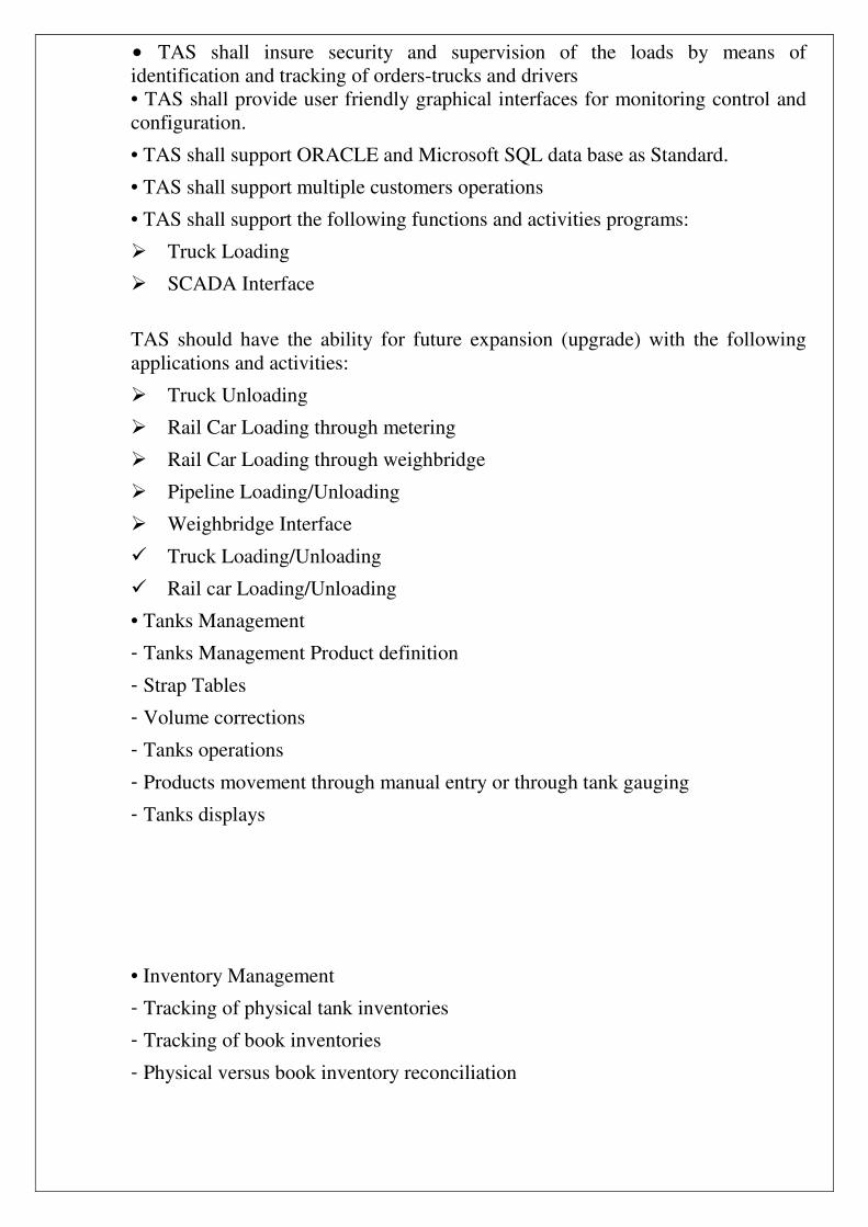
• TAS shall insure security and supervision of the loads by means of identification and tracking of orders-trucks and drivers • TAS shall provide user friendly graphical interfaces for monitoring control and configuration.
• TAS shall support ORACLE and Microsoft SQL data base as Standard.
• TAS shall support multiple customers operations
• TAS shall support the following functions and activities programs:
��Truck Loading
��SCADA Interface
TAS should have the ability for future expansion (upgrade) with the following applications and activities:
��Truck Unloading
��Rail Car Loading through metering
��Rail Car Loading through weighbridge
��Pipeline Loading/Unloading
��Weighbridge Interface
� �Truck Loading/Unloading
� �Rail car Loading/Unloading
• Tanks Management
- Tanks Management Product definition
- Strap Tables
- Volume corrections
- Tanks operations
- Products movement through manual entry or through tank gauging
- Tanks displays
• Inventory Management
- Tracking of physical tank inventories
- Tracking of book inventories
- Physical versus book inventory reconciliation

- Tank-to tank transfers
- Bulk receipts
- Product gain/losses
• Tank Gauging Interface through OPC or MODBUS
• Orders Management of clerk entered orders
• PLC control
• Gates control
• Bay allocation & Queue display
• Tank Truck Automation/Fleet Management PLC System PLC System shall be mounted on a cabinet with necessary hardware and accessories to provide the following controls:
o Products pumps (loading pumps) o Transfer pumps (feed to the storage tanks) O ESD (Emergency Shut-Down) ���ESD buttons shall be installed in various locations accessible by the operators such as loading gentries, tank farms, control room, entry/exit gates. o FFS(Fire Fighting System) ��Fire-fighting system shall be managed by a separate PLC o MOV(Motor Operated Valves) ��Tank inlet-outlet valves shall be motorized and controlled by PLC system. Motorized valve actuators shall be connected to the PLC system via Profibus and/or Device Net. ��The actuators shall have electrical socket connector for quick connection and replacement. ��All adjustment shall be made at the actuator local control unit. ��The actuators shall not use battery backup unit for storing the configuration parameters. ��Inlet and Outlet Valves shall be double block and bleed gate valve or Ball valve o MCC (Motor Control Centre) ��An MCC Panel complete with all necessary accessories to provide required

functionality. ��Product pumps shall be controlled by frequency convertor. Detailed technical specifications to be provided by the supplier.
Access control Gates shall be installed at the refinery entry and exit points, access gates shall support card readers to control entrance and exit of the trucks under supervision of the automation system. Bidders shall provide a compatible access gates units.
8-13 Control Philosophy.
The Control system and the conventional control panel shall perform the following main tasks as:
- Total information system and supervisory control continuous and sequential �����control functions of the plant.
- Process and system alarm management with sequence of events
- presentation automatic process data storage and historical data management
The control system shall consist of the following main components: • Control unit as process interface which shall handle the input/output
communication, process controls and the communication with the operator interface.
• Operator stations for process monitoring and operating with LCD displays, keyboards, printers, etc.
• Communication network (BUS system) between all control modules. Engineering station with elements for system configuring and tuning
8-14 General Specification .
The whole control system shall be divided into divided into three levels: LEVEL I Process Level LEVEL II Process Bus
LEVEL III Supervisory Level
LEVEL I Process Level The main function of process level is to convert physical I/O signals into
numbers and calculate of control algorithm. This level shall include the following components: Programmable controller modules I/O modules for analogue signals I/O modules for discrete signals .

LEVEL 11 Process Bus The process bus shall consists of the dual communication data highway
(Ethernet) with necessary interface equipment. The process bus shall connect operator and engineer station with process stations. The medium of process bus cables shall be dual twisted pair.
LEVEL III Supervisory Level From this level humans take over control of the plant through operator
stations and engineers maintain by means of engineer station. Operator stations are equipped with printers, LCD monitors, mouse , operator keyboards.
Operating and Monitoring Philosophy The control room shall house the Control operator stations (including monitors and keyboards) and color printers for alarms, reports, historical data, trends, etc. The independent operator stations shall be working under Windows XP operating system. For any operator station it shall be able to monitor and control only that section of the Plant to which the stations is dedicated. For the remaining sections the said operator stations shall be used as a "view only" station. In the event of failure of one of the operator stations, either of the remaining operator stations shall be capable of providing the full operational facilities for that section of the plant. This makes for full redundancy at the level of the display and operation.
The Control system shall provide the following types of visualization on the displays.
- Process graphics (schematics) based on P& l Diagrams with superimposed current readings for monitoring and controlling the plant.
- Individual and group-displays of measuring and control loops showing all relevant parameters.
- Alarm and state signal listings - Status displays of sequential control performances. - Trend recording� ��
8-14-1 Function Control system shall provide these main functions signal collection from sensors
and transmitters located in the field data processing sequence and analogue control .
• Data visualization for operator's �complete diagnostic of system printing measured values and alarms .
• Transmission of data and commands from operator level to process . 8-14-2 Control system overview. The system shall be IP/Network type with high reliability and quick response
and achieves steady response with little delay even under heavy load. Using general-purpose network equipment conforming to IEEE802.3 and UDP/IP standards, it shall realize open-based communications. And can connect to a network system.

8-14-3 Control system Components
8-14-4 Operator Stations An Operator stations serves as a human interface for operation, monitoring,
and engineering. Software packages installed in a general-purpose personal computer (a compatible computer, hereinafter referred to as a general purpose PC), consisting of a general purpose PC and Open Display Style Console Assembly, implement operation and monitoring functions as well as engineering functions. Users can install and run operation and monitoring functions and/or engineering functions in an HIS as necessary. For connections to the Control Bus Interface Card shall be used.
8-14-4-1 Field Control Devices (FCD) The FCD shall perform process control and manages communications with
subsystems such us (flow computer, instruments, etc.). 8-14-4-2 Tank management PC already exist Tank management PC shall be installed in control room connecting with a HIS
PC via OPC to retrieve the data for the TAS. 8-14-4-3 Fire Fighting System FFS The Fire Fighting system shall be managed with a separate PLC that manages
the communications with the valves, alarms, etc. 8-14-4-4 Layer Switch This is a device to connect equipment within the IP/network domain. The layer
switch, unlike a HUB, shall incorporate bridge functions to send data to the destination terminal equipment only.
8-14-4-5 Communication shall be via redundant separately routed communication channels to a centralized control room. Redundant communication shall be standard feature of the system
8-14-4-6 DATA BASE SERVER Control system TAS shall connect to Data base servers with SQL or Oracle using to saving the BOL and all data transactions with redundant, the servers should be kept in safe area and isolated from the network with virus protection.
8-15 Each operator station shall be entirely independent, consisting of high-resolution
19" inch color. CRT monitor keyboard located in front of each CRT monitor which shall enable the user to perform operating, tuning, and con figuring functions using depicted keys. Key lock shall be provided for security (password)
Portion of key board shall have lighted buttons push buttons in matrix form, each
push button corresponding to one operating group in an overview display when

station is used as operating station or to the one alarm group when station is used
as alarm as alarm station.
Operator keyboard shall include all required capabilities for set up,
configuration, and process operation. Electronic that includes microprocessor that enables to configure operator station, support the key board, display alphanumeric, semi graphic and live graphic (mimic) information on the screen , drive printer or recorders, communications with other devices connected in the system.
- Floppy disk system shall have saved and restore all of information contained in the random access memory of the controllers and process interface unit, as well save restore configuration of the operator station. The printer interface card printer shall be capable to print alarms, logging, trending, screen display.
8-16 Standards Operator Station LCD Displays - Overview display It is organized display all of the important control points at the process.
Dedicated push buttons on the keyboard shall corresponds and are organized in the same manner as overview display. Each push button correspond to one group displayed. Operator shall be monitor deviations from set point, alarms modes.
- Group display This display shall provide many separate group. Each group shall have a
number and title. This display enables operator to see operating details of each control point configures in the displayed group as well as to manipulate selected control point. Any point in the system shall be able to be configured In any group. Total capacity shall be organized in groups of suitable number of points. Both analog points and digital points shall be displayed graphically and numerically.
- Detail display This display shall provide separate display for each point . This display shall
present all information such as tuning constants operating parameters configuration information . Some of data entries shall be protected via key lock (pass word). Operator shall be in tabular formats showing the last ten hours overages. This display corresponds to a group currently displayed. Hourly average shall be in tabular format showing the last ten hours average. This display corresponds to a group currently displayed. Trendy display shall be shown as one or two point trend, with various time bases. Communication status

In case of malfunctions this display shall indicate nature and location of failure.
- Device diagnostic display provides operator with detailed information of failed device like device number, and type description, error code and description. Graphic (mimic) display.
- It shall be possible to configure a library of shapes, which shall be possible to combine into live graphic displays. These displays shall also show dynamically correct measurements, alarms and states of equipment, etc.
8-17 Alarm monitoring . Each operator station shall be capable of alarm monitoring.
Available alarm shall be of absolute or deviation type. Operator shall be alerted by horn and visually, on alarm occurrence. Alarm summary display shall alert the operator when points are in alarm and shall list item as they occurred sequentially. The printer shall print time, type and description of alarm. Alarm group display shall be able to display on any operator station. The size alarm group shall be selectable. Alarm could be disabled. System alarm shall be presented to the operator when there is a system related malfunction
8-18 Operator station shall be to initiate the following print outs . Real time trending.
- Historical trending. - Tabular print out. - CRT screen print out. - Automatic alarm prints out
8-19 Recording Following recording shall be available dedicated recording.
Recorders shall be wired directly to termination panels, Trend recording. Operating shall be able to select any configured group for trend recording.
- Dedicated via communicate system shall be possible to Provide real time dedicated recorders for recording points available in the communication system.
8-20 System Communication
System shall allow rapid and reliable transfer of information between operator stations and I/O devices.
Communication shall be redounded, both III cables and electronic. In case of failure switch over is automatic .Communication shall not be ambiguous
- Each device can be connected for disconnected without affecting system. - Error detection shall be provided as

- Cyclic error detection code. - Geometric pulse pattern. - Transmission acknowledgment, by the receiving device.
8-21 System shall have distributed data base. The data base is the configuration
information stored In the devices microprocessor driven memory, which is part of interface and control selects a particular control strategy including the following parameters:-
- Signal conditioning. - Operational mode status. - Algorithms. - Control constant.
8-22 System Available . System shall be designed so that control functions are distributed on modular basis
to distribute risk. Control functionality shall not depend on a control based device or communication system. Control device shall be to minimize the consequence of failure. The control system shall be redundant except for the I/O’s in case of a fault with the main controller. The redundant unit shall take over control within one second without disrupting system operation.
1. System Documentation a- In addition to standard hardware and software documentation vendor shall
supply four (4) sets of the following:- System cabling schedule .
- Field I/O Wire Lists in point ID Order. - Loop wiring diagrams generated by loop ordering computer software . - Application and custom program descriptions and source listings . - Memory maps .
b- Documentation shall be up dated to the level at time of shipment, free of
errors
2. Engineering a- Process control Strategy shall be defined the contractor
Who shall assume functional responsibility? b- Block Data forms, supplies by venders shall be completed
Be the and reviewed by vendor. c- Entry and generation shall be done by vendor with 100% verification of
data. d- Checkout shall consist of point by point input/output checks of 100% of all
blocks by vendor.

The remote devices must be staged at vendor with shipping and repackaging expenses not included in this proposal. Maintenance of the remote equipment during system checkout shall be the customer's responsibility.
e- Management Information Logs and Reports are included upon definition. f- Engineering for design and implementation of system interface with other
controls or devices shall be included pending detailed definition by the contractor.
ARTICLE (9) CIVIL REQUIREMENTS
9-1 STANDARDS AND CODES . The following standards or the equivalents shall constitute as a guide for design .
a- A.C.I American Concert Institute. b- ANSI American National Standards Institute. c- AISC American Institute of Steel Construction. d- All materials imported must conform to ASTM (American Society for
testing material) local material shall conform to the local IRAQI Codes.
9-2 Drawing and document required: The following document shall be submitted to MRC for approval 9-2-1 Detailed civil Engineering design 9-2-2 Building plan, elevation and section including all installation and service. 9-2-3 Layout drawing and under ground piping and drainage. 9-2-4 Drawings of cross-section of road and dikes. 9-2-5 Grading plan (if applicable). 9-2-6 Pilling plan and specification, if needed. 9-2-7 Typical standard drawing. 9-2-8 General plat plan. 9-2-9 Static and dynamic calculation. 9-2-10 Drawing shall completely show construction works ,all dimensions of the
shape, sections, relative location, floor levels, column centers, connection members and concrete reinforcement, Bar Bending and anchor Bolts position and level, and any other details required to complete the construction of civil work. The drawing shall be to a scale large enough to convey adequately the required information.

9-3 Soil Condition: a- All information about soil layer shall be given in soil investigation report. b- The load bearing of soil in general is 5 ton/m2 at one meter depth.
9-4 The height of ground water level shall be 1.5 meter at April, 4 meter in
November . Area elevation above sea level is approximately 30 meter. 9-5 Material for construction The following material shall be supplied by MRC a- Cement. b- Sand and gravel.
c- Reinforcement bars. d- Terrazzo tiles - plastic tiles. e- Asbestos cement sheet. f- Sheet for roofs (galvanized and metal types). g- Brick (23.5 x 11.5 x 7.5 cm thick).
h- False ceiling materials. i- Doors and windows. (Except class shall be supplied by bidder and it shall be
reinforce glass type of 6 mm thick) as sheet. Any other material required for the plant construction shall be supplied by
contractor. 9-6 Control Building & MCC Room It is consist of : a- Control room. b- Rooms (4 5) Labor (workers) . c- MCC Room . d- Order entry and exit Room. 9-7 General Notes a- All the foundation shall be at 1.00 meter depth. b- The sulphate resistant cement shall be used, the minimum weight of cement
shall be 380 kg/m3 of concrete. c- Concrete in contact with soil shall be coated by 3-layers of bitumen coat
(flunkout or similar) as approved by MRC office. d- All roads and Paving area: all roads, pavements other than walk way shall be
of sufficient width and strength to handle cranes operation.

9-9 Painting a- All the equipment, piping and steel structure shall be primary coated, all
painting material required for (three final) coating at site. Shall be supplied by Bidder.
b- Any concrete area in contact with chemical material shall be coated with proper type of Epoxy.
9-10 Anchor Bolts and Bolts and nuts All anchor Bolts and bolts and nuts required for the project shall be supplied by
Bidder. Every type shall be packed and numbered according to the places where it is used.
9-11 Sewer and Drainage System: a- Soil, water waste from closed and urinals washroom, etc. Shall be connected
to aseptic tank and over flow shall be connected to the sewer pit. b- Process drains shall be separately connected and fed to the waste water
collection basin.
c- Rain water drains shall be separated and it is connected to the waste water d- The waste water from the collection pit shall be pumped to the waste water
treatment unit or API, Basin e- All pipes and accessories for sewer drainage system shall be supplied by
contractor. 9-12 Cable trench : Cable trench: All cables shall be laid in a concrete trench with proper width and
depth covered with concrete slabs. 9-13 Steel structure: The steel structure for the pipe and equipment supports shall be prefabricated
steel shop's. The scope of supply shall include :
a- Complete design. b- Complete supply of materials.

ARTICLE (10) INSPECTION REQUIREMENTS
10.1 Because of difficulty in making rectification and replacement in IRAQ, a high standard of inspection is required. ���
10.2 DAURA’S inspection department (here in referred to as the inspection authority) shall (for the purposes of the contract) be deemed to act on behalf of the M.R (General Manager of M.R).
10.3 All inspection and tests carried out by the inspection authority and/or the contractor’s inspection agents shall be performed in accordance with the standards mentioned in the contract, which is briefly mentioned below, to ensure complete adherence to the contract requirements.
ASTM standard. �For materials�ASME code section VIII requirements for atmospheric pressure .�
For pressure vessels�
class R requirements and ASME Code section VIII requirements.
For exchangers TEMA �

�
ANSI B-31.3 requirements�For piping�ANSI B-16.5 requirements For fittings�
�
10-4 The contractor should be responsible for supplying the inspection authority in good time after signing of the contract between M.R and the contractor with all drawings, specifications and design documents .
The inspection procedure and inspection methods that are required for the performance of the inspection works at the manufacturer's shops and at the site for M.R approved prior to the commencement of the inspection.
10-5 The compliance with the specifications contained in the contract documents shall be the responsibility of the contractor in accordance with the terms of the contract and in case of conflict between the contract specifications and/or code requirements (referred to in the contract) the most stringent requirement should be apply. 10-6 The contractor’s inspectors should be responsible for full dimensional checking of items and for seeing that all points mentioned in these inspection requirements are observed. The Contractor and/or manufacturer should have own routine inspection activities for quality control, which can be preceded on their own free independent schedules regardless of the presence of the inspection authority. It is to be understood that inspection authority activities (in shops or at site) do not relieve the contractor from contractual obligations. 10-7 Inspection certificates, shop test certificates, fabrication certificates, performance test certificates and all other certificates and reports should be issued in English language by the contractor inspection agent at the completion of inspection and tests of equipment and should be approved by Daura inspection department (inspection authority) for the purpose of acceptance .For the equipment which dose not require to be inspection by contractor

inspector. the contractor should provide certificate of quality issued by the manufactures works. 10-8 The inspection certificates and all other relevant certificates mentioned in clause (7) shall be issued in (4) copies and shall be handed over to the M.R. 10-9 The contractor shall be responsible for the supply, inspection completion and expediting of materials and equipment required to complete the work and arrange for the safe transportation of the same to the job site.
10-10 The inspection authority shall delegate to the site such number of inspection technicians and engineers as the work requires. The decisions of the inspection authority for accepting or rejecting the workmanship during construction shall be considered as final and the contractor shall accept such decision. It is to be understood that the inspection authority certificates do not relieve the contractor from his contractual obligations. Contractor must provide the inspection authority with a minimum of two full sets of project documentation for construction at site.

Vendor list Only vendors from USA, Western Europe and Japan, Turkish and Korean are accepted the following list is the preferred one for the equipment any other suggested company is subjected to MRC approval. (Turkish and Korean) manufactures acceptance is subjected to MRC technical Authority according to the manufacture profiles 1-Pumps : A- HORIZONTAL CENTRIFUGAL TYPE , API DAVID BROWN UNION PUMPS EBARA GOULDS PUMPS RUH RPUMPEN RUH PRUMPEN SULZER PUMPS K.S.B B- Electric Motors Schorch �� ��ABB �� Siemens � �Loher� Flender Brook 3- Electrical Equipment �A- Lighting Fixture , push Button distribution material and other
Explosion proof material Stahl Legrand Schneider Electric
B- Cables BICC General Electric Siemens � Cables Pirelli C- Battery & Battery Changer Saft-Nife Varta Chloride D- Motors Scorsh ABB Brook 4- Instrumentation:

DCS Yoko gawa Foxboro ABB Emerson Honeywell Smith meter Endress + Hauser �
PLC� Allen Bradley Honeywell Siemens Omron GE Flow Instrument Foxboro Yokogawa Emerson Finsher � Honeywell Smith meter Control Valves Masoneilan Foxboro Fisher Smith meter 5- Pipes and Fittings - TPS TECHNITUBE (DE) - OGTG(DE) - TC(FR) - PIETRA(IT) - SHAW GROUP (UK) - KAWASAKI (JP) - THYSSEN MANNESMANN - US STEEL - VALLOURERC(FR) - SUMITOMO - TUBOS REUNIDOS - ERNE (GB)\ - BSL (FR)

- NIPPON BENKAN KOGYOCO(JP) - BRUCK(DE) - IML (IT) - DELCORTE(FR) - SIDDRO(DE) 6- Valves - TROUVAY&CAUVIN - BABCOCK BORSIC - CRANE - ECONOSTO - ORION - VELAN - VITAS - ALCO - VOGT - KEYSTONE - Auma ��