
Midilift SLplus Platform Lift - Stannah Lifts Technical ... SLplus/SLplus Install... · Midilift...
72
Midilift SLplus Installation Guide 04-09-13 Issue 1 1 Midilift SLplus Platform Lift (Cabin with hydraulic drive) Installation Guide
-
Upload
truongthien -
Category
Documents
-
view
291 -
download
17
Transcript of Midilift SLplus Platform Lift - Stannah Lifts Technical ... SLplus/SLplus Install... · Midilift...

Midilift SLplus Installation Guide
04-09-13 Issue 1 1
Midilift SLplus Platform Lift
(Cabin with hydraulic drive)
Installation Guide

Midilift SLplus Installation Guide
04-09-13 Issue 1 2
Contents
1 SITE REQUIREMENTS AND TOOLS 5
1.1 Site arrival 5
1.2 Installation tools 6
2 SAFETY EQUIPMENT AND PRECAUTIONS 8
2.1 Personal protective equipment 8
2.2 Danger / Warning symbols 8
2.3 General safety precautions 8
3 SETTING PLUMB LINES 9
3.1 Plumbing and marking structure position 9
4 LOWER STRUCTURE INSTALLATION 10
4.1 Preparation for lower installation 10
4.2 Fitting lower corner uprights, base plate and horizontal members 11
4.3 Preparing a 2 stage ram for installation (travel < 3.6m) 14
4.4 Installing a 2 stage ram (travel < 3.6m) 15
4.5 Ram guide rails (3 stage rams only, lift travels ≥ 3.6m) 17
5 SLING INSTALLATION 18
5.1 Car guide rails 18
5.2 Fitting sling to car guide rail 18
5.3 Fitting lower door zone ramp and bottom reset switch bracket 19
5.4 Lower door frame installation 20
5.5 Access ramp (only required when a pit is not available) 22
5.6 Installation of the Trailer Connection Box (TCB) 23
6 STRUCTURE INSTALLATION (CONTINUED) 24
6.1 Attaching the temporary work platform to the sling 24
6.2 Installing next structure level from the work platform 25
6.3 Installing next set of car guide rails 26
6.4 Installing infill panels above the lower door frame 27

Midilift SLplus Installation Guide
04-09-13 Issue 1 3
7 INSTALLING A 3 STAGE RAM (FOR 2 STAGE RAMS SEE SECTIONS 4.3 & 4.4) 28
7.1 Attaching the chain hoist to the structure and sling 28
7.2 Hoisting the sling and securing it in a raised position 29
7.3 Setting up the ram retaining strap 30
7.4 Connecting the ram to the chain hoist & raising ram 31
7.5 Securing the 3 stage ram in position 32
7.6 Installing the intermediate ram guides, ram guidance assembly & oil reservoir 33
7.7 Installing the Trailer Connection Box (TCB) 34
7.8 Lowering the sling to the pit floor using the chain hoist 34
8 DOOR INSTALLATION 35
9 CONTROL PANEL & TRAILING CABLE INSTALLATION 38
9.1 Installing the control panel 38
9.2 Installing the trailing cable chain 39
9.3 Installing the trailing cable cover and guidance channel 40
9.4 Cable routing and cover panel 41
10 HYDRAULIC PUMP UNIT 42
10.1 Mounting the pump unit 42
10.2 Connecting the pump unit 43
10.3 Bleeding the ram 44
11 SLING INSTALLATION (CONTINUED) 45
11.1 Fitting lower sling braces and cross angle 45
11.2 Attaching the floor assembly 46
11.3 Attaching the support chains 47
11.4 Running clearances 48
11.5 Guide end stop for installation stage (IMPORTANT HEALTH & SAFETY PROCEDURE) 49
12 SECURING THE STRUCTURE 50
12.1 Squaring the structure & fixing it to load bearing walls 50
12.2 Fixing the structure to the building floor 52

Midilift SLplus Installation Guide
04-09-13 Issue 1 4
13 INTERMEDIATE & UPPER DOOR / FRAME INSTALLATION 53
13.1 Fitting door frame threshold plate 53
13.2 Fitting intermediate / upper door frame 54
13.3 Fastening door frame to building threshold 55
14 UPPER STRUCTURE INSTALLATION 56
14.1 Fitting top corner uprights 56
14.2 Fitting upper structure panels, door frame and door 58
14.3 Installing upper car guides, guide end stops & upper ram guides 59
14.4 Installing the structure ceiling bracing 62
14.5 Landing call station - standard 63
14.6 Landing call station - fire clad 63
15 CABIN FRAME INSTALLATION 64
16 INSTALLING THE LIFT POSITIONING ENCODER 65
17 CABIN INTERIOR INSTALLATION 65
18 HYDRAULIC CONTROL VALVES 66
18.1 Hydraulic control valves - overview 66
18.2 Hydraulic control valves - adjustment 67
19 TROUBLE SHOOTING 68
20 SAFETY CHAIN SWITCH LOCATIONS 69
21 COMMISSIONING 71
22 DOCUMENT HISTORY 72

Midilift SLplus Installation Guide
04-09-13 Issue 1 5
1.1.1. On arrival at the site, the installer should make his presence known to the customer. The installer must comply with any site safety procedures and regulations that are in force.
1.1.2. Before commencing the installation, it is important to ensure that the power supply has been fitted
according to the requirements of the builder’s work and electrical schedule. 1.1.3. It is important to check that:
• The position of the power supply and route to the trailer connection box are according to the site plan.
• Lift travel, pit depth (if applicable) and headroom dimensions accord with the arrangement drawing.
• An adequately clear working area, free from carpets and furniture, has been provided in all areas in which the lift will travel.
• Piping or cables not related to the lift installation have been adequately protected or re-routed away from the lift path.
• All decor disturbed during the building work has been adequately made good.
• A dedicated single phase 240V power supply, terminating in a 16 amp switched fuse spur unit, has been provided.
• All lift parts have been received and are not damaged.
Should any of the above be incorrect or not available, consult the installation manager.
1.1.4. All carpet areas, walkways and any remaining furniture in the vicinity of the lift is to be protected with dust sheet. Avoid any undue disruption.
1 SITE REQUIREMENTS AND TOOLS
1.1 Site arrival

Midilift SLplus Installation Guide
04-09-13
Before using any of the installation tools, it is important to check for each tool is safe to use.
1.2 Installation tools
Description
Plumb lines
Temporary work platform
Lower platform support chain
Support chain anchor brackets
Electric hoist (500Kg) OR
Manual hoist (500Kg)
It is vital that the hoist (electric or manual) is properly maintained and checked every 6 months.
Issue 1
Before using any of the installation tools, it is important to check for damage / corrosion to ensure that each tool is safe to use.
Description
Temporary work platform
Lower platform support chain
anchor brackets
Electric hoist (500Kg)
Manual hoist (500Kg)
It is vital that the hoist (electric or manual) is properly maintained and checked every 6 months.
6
mage / corrosion to ensure that
Fig.

Midilift SLplus Installation Guide
04-09-13
Upper hitch brackets (Attached to the temporary work platform)
Temporary work platform hanging brackets
• Upper pair (attached to the sling assembly)
• Lower pair (installation tool)
Dee Shackles x 2
Removable lifting channel
Sling locking brackets
Pendant control box
Installers DDU & speaker box
Ram bleeding kit
Eyebolt M16 x 260mm
Issue 1
(Attached to the temporary work platform)
Temporary work platform hanging brackets:
ttached to the sling assembly)
(installation tool)
Removable lifting channel
Sling locking brackets
Installers DDU & speaker box
Eyebolt M16 x 260mm
7
a
Midilift SLplus Installation Guide
04-09-13 Issue 1 8
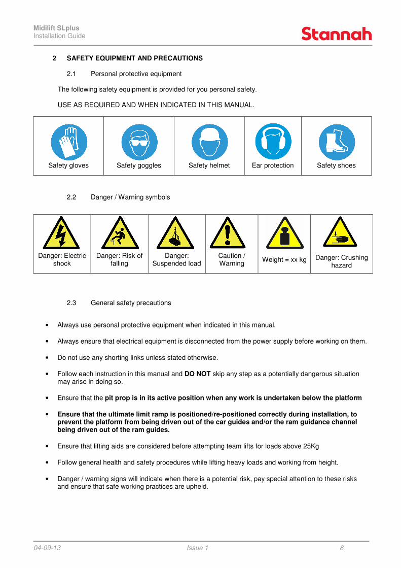
The following safety equipment is provided for you personal safety.
USE AS REQUIRED AND WHEN INDICATED IN THIS MANUAL.
Safety gloves
Safety goggles
Safety helmet
Ear protection
Safety shoes
Danger: Electric shock
Danger: Risk of falling
Danger: Suspended load
Caution / Warning
Weight = xx kg
Danger: Crushing hazard
• Always use personal protective equipment when indicated in this manual.
• Always ensure that electrical equipment is disconnected from the power supply before working on them.
• Do not use any shorting links unless stated otherwise.
• Follow each instruction in this manual and DO NOT skip any step as a potentially dangerous situation may arise in doing so.
• Ensure that the pit prop is in its active position when any work is undertaken below the platform
• Ensure that the ultimate limit ramp is positioned/re-positioned correctly during installation, to prevent the platform from being driven out of the car guides and/or the ram guidance channel being driven out of the ram guides.
• Ensure that lifting aids are considered before attempting team lifts for loads above 25Kg
• Follow general health and safety procedures while lifting heavy loads and working from height.
• Danger / warning signs will indicate when there is a potential risk, pay special attention to these risks and ensure that safe working practices are upheld.
2 SAFETY EQUIPMENT AND PRECAUTIONS 2.1 Personal protective equipment
2.2 Danger / Warning symbols
2.3 General safety precautions

Midilift SLplus Installation Guide
04-09-13 Issue 1 9
3 SETTING PLUMB LINES
3.1 Plumbing and marking structure position
Before commencing installation of the lift, plumb lines need to be dropped to ensure the lift is positioned correctly. Starting from one side of the top landing entrance, drop a plumb line and mark its position at the lower floor. Repeat at the other side of the landing entrance so that a line can be drawn that is parallel with the landing floor. This needs to be repeated for each landing. Using the markings made from laying the plumb lines, the floor that protrudes the most will be indicated. Use this landing as a datum. On smaller travel lifts (up to 5m) it is possible to move the base of the lift into position using a large lever (crowbar). However, the above process is still recommended to ensure that the lift structure will pass through each floor aperture before commencing the installation.
Upper landing
Mid landing
Lower landing
Plumb Line

Midilift SLplus Installation Guide
04-09-13 Issue 1 10
4 LOWER STRUCTURE INSTALLATION
4.1 Preparation for lower installation
Once the landing entrance datum line has been drawn, it is possible to position the first components correctly. Extend the landing entrance datum line back to the guide wall. Place the first corner upright against the guide wall and in line (outer edge) with the landing datum line. The next corner uprights and horizontal members (HM’s) can then be placed in their correct positions.
GUIDE W
ALL
UPPER LANDING
C
A B
GUIDE W
ALL
UPPER LANDING
1600.0
1510.0
NOTE: Be sure to use the correct corner uprights for the lower structure.
They can be identified by two rectangular cut-outs near the bottom; they also have a plate welded flush with one end.

Midilift SLplus Installation Guide
04-09-13 Issue 1 11
4.2 Fitting lower corner uprights, base plate and horizontal members
Once parts are near their final position, fix together using M8 screws and contact washers. To square the lift, measure the diagonal distance between corner uprights, each diagonal should be the same dimension. If not, then adjust their position and check again, repeat until the diagonals are equal. Using a spirit level and supplied packers, ensure that the lower horizontal members and base plate are level. An M16 nut is welded to the base of each corner upright. Use this with an M16 bolt to jack the structure up to allow packers to be placed underneath. Once the structure has been levelled, unwind the bolts to ensure the weight is supported on the packers and not the M16 bolts. Once the structure is levelled, pack between the base plate and pit floor directly underneath the ram, car guides & pit prop base plate (these are where vertical loads need to be transmitted to the pit floor).
M8 x 20 hex hd screws & contact washers
IMPORTANT: Lower horizontal members are steel channels with removable cable covers. All other horizontal members are aluminium extrusions.
Pit stop switch (entrance side)
NOTE: The stop switch must be fitted to the end of the base plate nearest the bottom entrance.
NOTE: It is vital that the lift is installed as square as possible to avoid problems later on.
M16 bolt used to raise & lower each corner
Packers under corners to support structure
Once structure is level, pack between base plate and pit floor directly under ram, car guides & pit prop
Midilift SLplus Installation Guide
04-09-13
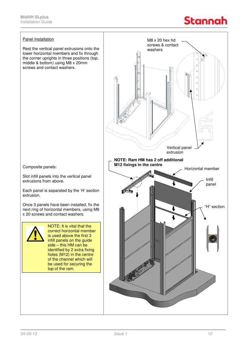
Panel Installation Rest the vertical panel extrusions onto the lower horizontal members and fix through the corner uprights in three positions (top, middle & bottom) using M8 x 20mm screws and contact washers. Composite panels: Slot infill panels into the vertical panel extrusions from above. Each panel is separated by the ‘H’ section extrusion. Once 3 panels have been installed, fix the next ring of horizontal members, using M8 x 20 screws and contact washers.
NOTE: It is vital that the correct horizontal member is used above the first 3 infill panels on the guide side – this HM can be identified by 2 extra fixing holes (M12) in the centre of the channel which will be used for securing the top of the ram.
Issue 1
Rest the vertical panel extrusions onto the lower horizontal members and fix through
s (top,
panels into the vertical panel
Each panel is separated by the ‘H’ section
Once 3 panels have been installed, fix the members, using M8
M8 x 20 hex hd screws & contact washers
Vertical panel extrusion
the correct horizontal member is used above the first 3 infill panels on the guide
identified by 2 extra fixing holes (M12) in the centre of the channel which will be used for securing the
NOTE: Ram HM has 2 off additional M12 fixings in the centre
12
screws & contact
Vertical panel extrusion
Infill panel
“H” section
Horizontal member
NOTE: Ram HM has 2 off additional

Midilift SLplus Installation Guide
04-09-13
Glass panels: Firstly, place three 30mm tabs of insulating foam into the lower HM channel or ‘H’ section channel for the glass panel to sit on. Using suction cups slide one side of the glass panel as far into the vertical panel extrusion as possible (1). Pivot the glass so that it lines up with the vertical panel extrusion on the opposite side (2). Slide the glass back so that it is supported either side (3). Slide the glass panel down into lower HM channel or ‘H’ section channel (4). Finally, feed a length of plastic tubing down either side of the glass panel to securlateral movement (5). Repeat steps (1) to (5) for each individual panel of glass.
Using the panels as a fall arrest barrier:
NOTE: to fit upper panels / glass, use the lower panels as a barrier to safeguard against falling out of the shaft.
Always maintain all 4 sides up to the same level. Ensure that the platform is a MINIMUM of 900mm below the uppermost panel. Always use the panel limit switch tool to avoid accidentally over travelling past the 900mm limit.
Issue 1
place three 30mm tabs of insulating foam into the lower HM channel or ‘H’ section
lide one side of the glass panel as far into the vertical panel extrusion
that it lines up with the vertical panel extrusion on the opposite side
Slide the glass back so that it is supported
Slide the glass panel down into lower HM
ing down either side of the glass panel to secure it from
Repeat steps (1) to (5) for each individual
panels as a fall arrest barrier:
Glass >30Kg
1
3
5
NOTE: to fit upper panels
safeguard against falling
Always maintain all 4 sides up to the Ensure that the platform is
Always use the panel limit switch tool ing
13
2
4
5
Midilift SLplus Installation Guide
04-09-13
4.3 Preparing a 2 stage ram
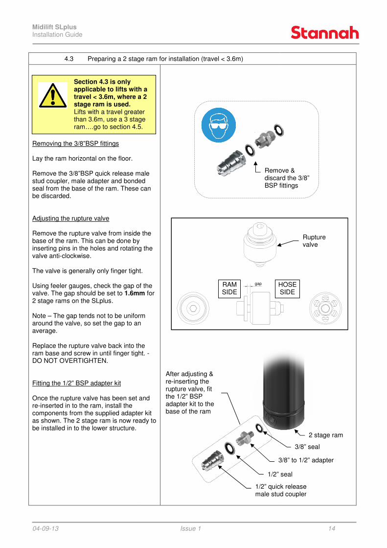
Removing the 3/8”BSP fittings Lay the ram horizontal on the floor. Remove the 3/8”BSP quick release male stud coupler, male adapter and bonded seal from the base of the ram. These can be discarded. Adjusting the rupture valve Remove the rupture valve from inside the base of the ram. This can be done by inserting pins in the holes and rotating the valve anti-clockwise. The valve is generally only finger tight. Using feeler gauges, check the gap of the valve. The gap should be set to 1.6mm2 stage rams on the SLplus. Note – The gap tends not to be uniform around the valve, so set the gap to an average. Replace the rupture valve back into the ram base and screw in until finger tight. DO NOT OVERTIGHTEN. Fitting the 1/2” BSP adapter kit Once the rupture valve has been set and re-inserted in to the ram, install the components from the supplied adapter kit as shown. The 2 stage ram is now ready to be installed in to the lower structure.
Section 4.3 is only applicable to lifts with a travel < 3.6m, where a 2stage ram is used. Lifts with a travel greater than 3.6m, use a 3 stage ram….go to section 4.5
Issue 1
a 2 stage ram for installation (travel < 3.6m)
Remove the 3/8”BSP quick release male and bonded
These can
from inside the base of the ram. This can be done by inserting pins in the holes and rotating the
The valve is generally only finger tight.
er gauges, check the gap of the 1.6mm for
The gap tends not to be uniform around the valve, so set the gap to an
valve back into the until finger tight. -
Once the rupture valve has been set and
components from the supplied adapter kit as shown. The 2 stage ram is now ready to
Remove & discard the 3/8” BSP fittings
3/8” to 1/2” adapter
1/2” seal
1/2” quick release male stud coupler
applicable to lifts with a < 3.6m, where a 2
Lifts with a travel greater than 3.6m, use a 3 stage
4.5.
After adjusting & re-inserting the rupture valve, fit the 1/2” BSP adapter kit to the base of the ram
gapRAM SIDE
HOSE SIDE
14
Remove & discard the 3/8” BSP fittings
2 stage ram
3/8” seal
3/8” to 1/2” adapter
1/2” seal
1/2” quick release male stud coupler
Rupture valve
HOSE SIDE

Midilift SLplus Installation Guide
04-09-13 Issue 1 15
4.4 Installing a 2 stage ram (travel < 3.6m)
Assemble the M12 studding, full nuts, contact washers & half nuts with one of the ram straps as shown. The studding should be wound in until it bottoms out at the rear of the horizontal member. IMPORTANT - Note the positions where half nuts are used. Adjust the position of the ram strap until the dimensions shown are achieved. This will ensure the ram is parallel to the structure guide side. Note - Final checks and adjustment to the ram alignment may be required once the structure is plumbed and secured. Position the 3mm thick ram spacer on top of the ram locating plate on the base plate. Lower the ram in to position ensuring that the spigot on the ram base passes through the hole in the ram spacer and in to the base plate locating hole. Orientate the ram inlet towards the hose route.
(51)
(21)
Half nuts – 2 off
Base plate
Ram spacer (required on 2 stage rams only)
Section 4.4 is only applicable to lifts with a travel < 3.6m, where a 2 stage ram is used. Lifts with a travel greater than 3.6m, use a 3 stage ram….go to section 4.5.
Full nuts – 4 off
Studding – 2 off
Contact washers – 6 off
Dimensions are from front face of HM to rear surface of ram strap
2 stage ram
IMPORTANT: 2 stage rams must have a 3mm thick spacer fitted to prevent the 1/2” quick release coupling from clashing with the ram location plate. 3 stage rams do not require the spacer.
Dimensions for 3 stage rams are different - please refer to section 7.3
2 stage ram ≈ 61kg

Midilift SLplus Installation Guide
04-09-13 Issue 1 16
Secure the ram with the second ram strap using half nuts, contact washers & full nuts as shown. IMPORTANT - Note the positions where half nuts are used. Ensure that the ends of the studding do not protrude in to the running path of the sling. Cut the exposed ends of the studding if necessary.
Ensure that studding does not protrude in to running path of sling
Half nuts – 2 off
Full nuts – 2 off
Contact washers – 4 off
Check that the ram is plumb to the structure. This can be achieved by measuring at the top and bottom of the ram. The gap between the ram case and the top HM should be 3mm greater than the gap measured between the base plate flange and the ram case.
i.e. DIM TOP = DIM BOTTOM + 3mm This is due to the extra 3mm
thickness of the base plate angle.
DIM BOTTOM
DIM TOP
2 stage ram
Horizontal Member (HM)
3mm base plate angle

Midilift SLplus Installation Guide
04-09-13 Issue 1 17
4.5 Ram guide rails (3 stage rams only, lift travels ≥ 3.6m)
Fit the lower pair of ram guides in place, using the M8 fixings provided, as per the illustration.
M8 x 30 hex hd screw and contact washer
Section 4.5 is only applicable to lifts with a travel ≥ 3.6m, where a 3 stage ram is used. Lifts with a travel less than 3.6m, use a 2 stage ram and do not require ram guides….go to section 5.
M8 x 20 hex hd screws, contact washers & nuts
Ram guide
Ram guide joiner
Base plate

Midilift SLplus Installation Guide
04-09-13 Issue 1 18
5 SLING INSTALLATION
5.1 Car guide rails
Fix one ‘T’ section guide in place using M12 fixings and guide clips on the side opposite the lower entrance. The lower guide fixes to the base plate and the first horizontal member via a guide fixing bracket.
5.2 Fitting sling to car guide rail
Move the sling in to the shaft before the door frame is fitted. This allows greater access to manoeuvre the sling in to position. Locate the sling guide shoes on to the blade of the car guide.
M12 guide clips and fixings – 2 off
M12 x 30 hex hd screws, contact washers and nuts – 4 off
Car guide
Temporarily fasten sling to guide
Sling mass ≈ 81kg
NOTE: Ensure the correct guides are selected - the lower guides are
2500mm long.

Midilift SLplus Installation Guide
04-09-13 Issue 1 19
Remove the guide bracket (indicated in the illustration) to allow the second ‘T’ section guide to be inserted in to the sling guide shoes. Once the second guide is in position, re-install the guide bracket and fix the guide in place with M12 fixings at the guide bracket and guide base. The temporary tie fastenings can now be removed.
5.3 Fitting lower door zone ramp and bottom reset switch bracket
Once the sling is in position the ‘lower door zone ramp’ & ‘bottom reset switch bracket’ can be positioned and fitted. Fasten the lower door zone ramp assembly to the car guide using 2 sets of M12 guide fixings – the plunger of the door zone switch should align with the centre of the brass contact plate. The bottom reset switch bracket is fastened to the opposite guide using 4 sets of M12 guide fixings. The top edge of the bracket should be positioned 2100mm above the building floor. Both of these may require slight adjustment during commissioning of the lift.
Remove this guide bracket whilst installing the second guide rail
Lower door zone ramp: M12 guide clips and fixings – 2 off
Bottom reset switch bracket: M12 guide clips and fixings – 4 off

Midilift SLplus Installation Guide
04-09-13 Issue 1 20
5.4 Lower door frame installation
Preparation – cable access hole
Before fitting the door frame, take an approx measurement from the landing threshold to the centre of the slot in the door frame ‘Dim A’. Measure a distance up from the bottom of the call station structure upright that is equal to ‘Dim A + Pit Depth’ and mark the nearest hole. Using a step drill open out this hole to 20mm diameter. NOTE: The enlarged cable hole is required on the call station side only. Preparation – access ramp (when pit not available) Loosely fit three M8x20 hex head screws in to the underside of the door frame, ready for the installation of the ramp – refer to section 5.5.
Measure from threshold to centre of slot (Dim A)
Dim
A
Dim
A
Pit
Depth
Open hole out to Ø20mm

Midilift SLplus Installation Guide
04-09-13 Issue 1 21
Installing door frame into the structure. Remove the cover plates on the inside of the door frame to allow access for fixings. Position the door frame in between the corner uprights and use packers under the frame to ensure the threshold is level (pit only), then fix back in the positions shown (on each side of frame). A spacer plate & fixing plate are used on the lower fixings. The spacer plate sits within the rectangular cut out in the corner upright and the fixing plate sits on top of this, with the angle flange in contact with the inside of the corner upright (to stop the fixing plate from spinning). NOTE: the door frame sits 20mm off the lower floor/pit
Fixing plate
CAUTION: Door Frames weigh 60Kg.
Consider using lifting aids before attempting a team lift.
Frame spacer
Lower fixings (M8x20 hex hd screws & contact washers)
Intermediate fixings (M8x20 hex hd screws & contact washers)
Upper fixings (M8x20 hex hd screws, contact washers & nuts)

Midilift SLplus Installation Guide
04-09-13 Issue 1 22
5.5 Access ramp (only required when a pit is not available)
Slide the ramp in to position and attach it to the underside of the lower door frame using three M8x20 hex head screws. Note: The fixings can be accessed with a spanner from inside the pit area.
M8x20 hex hd screws – 3 off
Access ramp

Midilift SLplus Installation Guide
04-09-13 Issue 1 23
5.6 Installation of the Trailer Connection Box (TCB)
Attach the trailer connection box to the guide side horizontal member using an M8x20 hex head screw and contact washer. Ensure that the TCB is hanging vertically and then fasten it to the infill panels with four self drill screws through the holes provided in the box. Note: The TCB is always mounted to the left of the ram.
M8 x 20 hex hd screw & contact washer
Self drill fixings at 4 positions
TCB always mounted on the left
The Trailer Connection Box (TCB) is fitted at this point of the installation on 2 stage ram arrangements only.
For 3 stage arrangements, the TCB is fitted after the ram is installed (to avoid damaging the TCB during hoisting of the ram)…proceed to section 6.

Midilift SLplus Installation Guide
04-09-13 Issue 1 24
6 STRUCTURE INSTALLATION (CONTINUED)
6.1 Attaching the temporary work platform to the sling
Fasten the lower support brackets to the sling uprights using M8 x 20 flange hex hd screws. Hang the work platform from the temporary hanging brackets at the top of the sling uprights (pre-fitted in the factory). Secure the bottom of the work platform to the support brackets using the threaded feet and locking “wing nut”.
NOTE: Refer to the separate work platform installation manual to assemble the work platform & ladder correctly and safely.
NOTE: Always use the lower hook location holes so that the work platform is at its highest position.
Work platform fastened to lower support brackets
Work platform hooks on to upper brackets
Midilift SLplus Installation Guide
04-09-13 Issue 1 25
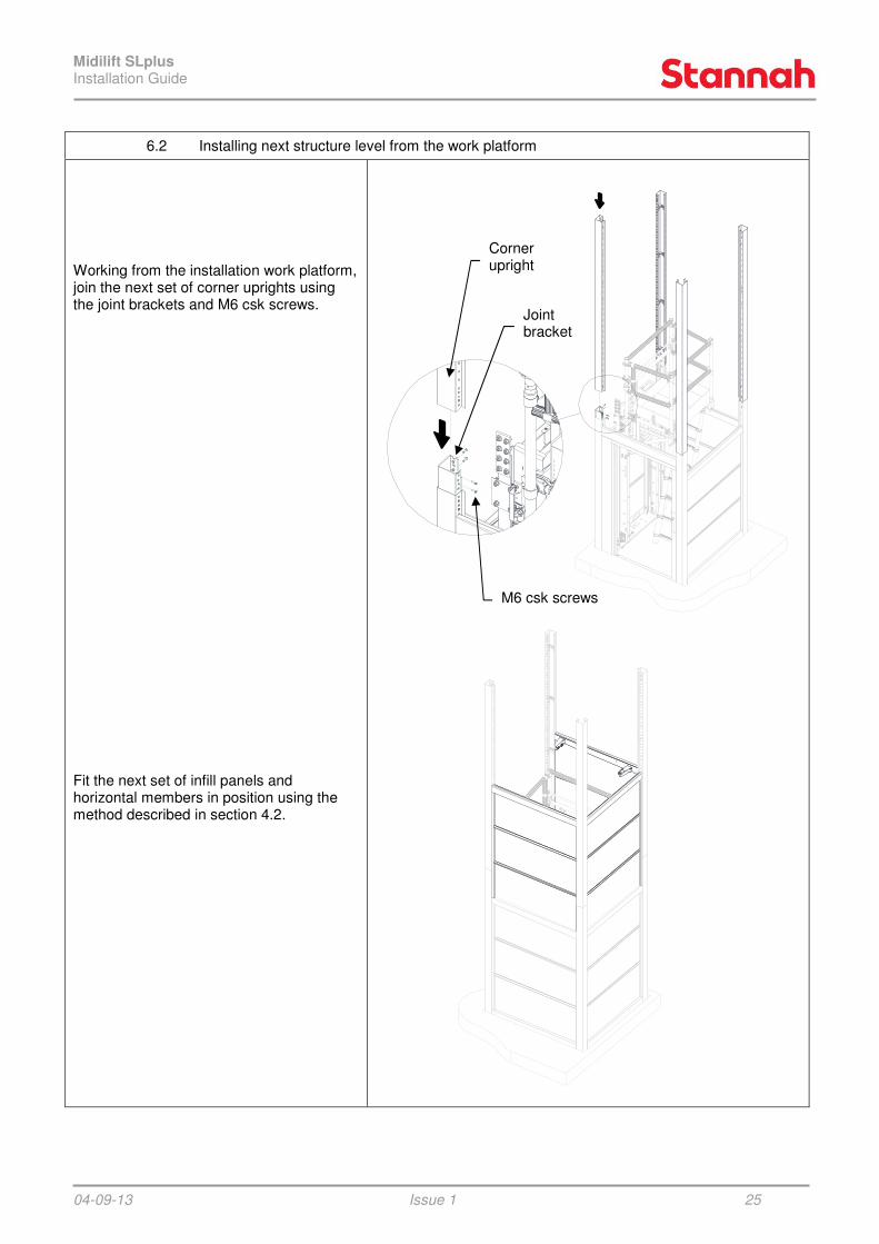
6.2 Installing next structure level from the work platform
Working from the installation work platform, join the next set of corner uprights using the joint brackets and M6 csk screws. Fit the next set of infill panels and horizontal members in position using the method described in section 4.2.
M6 csk screws
Joint bracket
Corner upright

Midilift SLplus Installation Guide
04-09-13 Issue 1 26
6.3 Installing next set of car guide rails
Using the fishplates provided, attach the next pair of car ‘T’ section guides. NOTE: ensure the guides are fixed back to the horizontal members using the guide brackets and guide clips. It may be necessary to file the front, rear and side faces of the guide blades at each joint to ensure a smooth ride when the cabin guide shoe passes over them.
Secure guide rail using M12 guide clips and fixings
Secure guide rail using the supplied M12 fixings and fishplates
NOTE: Ensure the correct guides are selected - the intermediate guides are
1850mm long.

Midilift SLplus Installation Guide
04-09-13 Issue 1 27
6.4 Installing infill panels above the lower door frame
The panels & vertical extrusions that lie beneath intermediate and upper door frames need to be cut to length. Use the formula below and the drawing opposite to calculate the correct cutting length, and then fit using the same procedure detailed in section 4.2.
Panel cut length formula: D = L – 182.0mm
Extrusion cut length formula:
E = L – 217.0mm As with the lower door frame, a hole in the corner upright needs to be opened out for cable access on the call station side of the door frame. Take an approximate measurement from the landing threshold to the centre of the slot on the door frame (Dim A), apply this measurement to the corner upright and pick the nearest hole to open out to 20mm. See section 5.4.
For 2 stage arrangements, skip section 7 and proceed to section 8
FFL
5,0
GA
P
PA
NE
L D
IM (
D)
EX
TR
US
ION
DIM
(E
)
17
7,0
19
7,0
(L)

Midilift SLplus Installation Guide
04-09-13 Issue 1 28
7 INSTALLING A 3 STAGE RAM (for 2 stage rams see sections 4.3 & 4.4)
7.1 Attaching the chain hoist to the structure and sling
Working from the work platform, place the lifting channel between the car guides so that it rests on top of the upper pair of guide brackets. Before attaching the chain hoist, ensure that the protective chain guards are in place on top of the sling. These prevent the chains from damaging the paint on the sling. Fasten a D-shackle to the lifting eye on the lifting channel, and then suspend the chain hoist from the D-shackle. Feed the chains through the two chain guards. The control chain and lifting chain should be run down opposite sides to avoid entanglement during hoisting. Fasten an M16 eyebolt through the central rear hole of the sling mid-channel. Two M16 full nuts should be locked together on the underside of the mid-channel. Fasten a D-shackle to the M16 eyebolt and attach the lifting hook to the shackle. Before raising the sling, the pit prop must be installed. Attach the pit prop leg to the pit prop base using an M16x50 hex hd screw and nyloc nut. Secure the pit prop to the base plate using the studs & fixings provided. Position it on the side nearest the lower entrance.
NOTE: Ensure that the guide clips are tightened and the guide brackets are screwed securely to the horizontal member before suspending any load on the channel!
Lifting channel (SWL 500kg)
Ensure all support fixings are tight
Ensure chain guards are in place
Chain hoist (min SWL 500kg)
Lifting channel SWL 500kg
2 x M16 full nuts
M16 eyebolt
D-shackle
Hook
Note: slot in base allows pit prop leg to be inserted. Be careful not to damage the micro-switch!
Pit prop located adjacent to lower entrance
Pit prop leg
Pit prop base
M16 screw & nyloc nut
Note: Work platform omitted for clarity

Midilift SLplus Installation Guide
04-09-13 Issue 1 29
7.2 Hoisting the sling and securing it in a raised position
Using the chain hoist, raise the sling until there is a gap of approx 750mm between the base plate and the sling buffer. The pit prop has a notch in its upper corner which must locate on the blade of the guide rail. If it does not align properly, small adjustments can be achieved using the slots on the pit prop base. If the pit prop is still misaligned it will be due to incorrect packing under the base plate – add or remove packers until the pit prop leg is parallel to the guide side wall. Once the sling has been raised to the position shown, it must be locked in place using two locking brackets, one each side of the sling. Once the sling is fastened in place and the pit prop is deployed, the lifting chain can be disconnected from the sling ready for hoisting of the ram.
Secure sling to ram guides (both sides) using locking brackets
75
0
(22
60
)
Deploy the pit prop to its active position whenever the sling is raised.
Ensure pit prop is deployed when sling is in a raised position
Locking brackets (both sides)
Always ensure the locking brackets are holding the sling & the pit prop is deployed before attempting to disconnect the chain hoist!
Notch in pit prop should engage with guide rail

Midilift SLplus Installation Guide
04-09-13 Issue 1 30
7.3 Setting up the ram retaining strap
Assemble the M12 studding, full nuts, contact washers & half nuts with one of the ram straps as shown. The studding should be wound in until it bottoms out at the rear of the horizontal member. IMPORTANT - Note the positions where half nuts are used. Adjust the position of the ram strap until the dimensions shown are achieved. This will ensure the ram is parallel to the structure guide side. Note - Final checks and adjustment to the ram alignment may be required once the structure is plumbed and secured.
Full nuts – 4 off
Studding – 2 off
Contact washers – 6 off
Dimensions are from front face of HM to rear surface of ram strap
Dimensions for 2 stage rams are different - please refer to section 4.4
Note: Sling omitted for clarity
Half nuts – 2 off
(35
)
(5)

Midilift SLplus Installation Guide
04-09-13 Issue 1 31
7.4 Connecting the ram to the chain hoist & raising ram
Attach the ram lifting eye assembly to the top of the ram using the M12 ram/carriage bolt and an M8 x 16 hex head screw. Attach a D-shackle to the ram lifting eye. Drop the lifting chain down behind the mid-channels of the sling. Safely manoeuvre the ram such that the lifting eye assembly is directly below the lifting chain. Connect the lifting hook to the D-shackle. Raise the ram up using the chain hoist, occasionally moving the base of the ram towards the structure (to ensure that the lifting chain remains as near vertical as possible). Once the ram is suspended above the base plate, carefully lower the ram in to position ensuring that the spigot on the ram base passes in to the base plate locating hole. Orientate the ram inlet towards the hose route.
Ram lifting eye assembly
M8x16 hex hd screw
M12 ram/carriage bolt
D-shackle
Ram liftingeye assembly
Chain hoist
Locating hole
Ram spigot
3 stage ram ≈ 102kg
Midilift SLplus Installation Guide
04-09-13 Issue 1 32
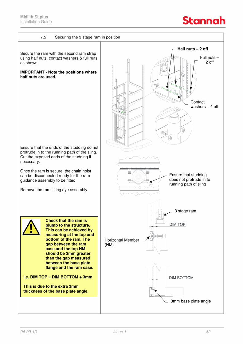
7.5 Securing the 3 stage ram in position
Secure the ram with the second ram strap using half nuts, contact washers & full nuts as shown. IMPORTANT - Note the positions where half nuts are used. Ensure that the ends of the studding do not protrude in to the running path of the sling. Cut the exposed ends of the studding if necessary. Once the ram is secure, the chain hoist can be disconnected ready for the ram guidance assembly to be fitted. Remove the ram lifting eye assembly.
Check that the ram is plumb to the structure. This can be achieved by measuring at the top and bottom of the ram. The gap between the ram case and the top HM should be 3mm greater than the gap measured between the base plate flange and the ram case.
i.e. DIM TOP = DIM BOTTOM + 3mm This is due to the extra 3mm thickness of the base plate angle.
DIM TOP
DIM BOTTOM
Ensure that studding does not protrude in to running path of sling
Half nuts – 2 off
Full nuts – 2 off
Contact washers – 4 off
3 stage ram
Horizontal Member (HM)
3mm base plate angle

Midilift SLplus Installation Guide
04-09-13 Issue 1 33
7.6 Installing the intermediate ram guides, ram guidance assembly & oil reservoir
Intermediate Ram Guides Install the second pair of ram guides, fastening through the guide, joiner and horizontal member, using M8 fixings. Ram Guidance Assembly Insert the ram guidance assembly in to the blades of the ram guides and slide it down on to the ram cap. Fasten the ram guidance assembly to the ram cap using 4 off M8x12 hex head screws and contact washers. The ram cap will need to be rotated to align with the ram guidance assembly – ensure the bleed screw is orientated towards the cabin. Note: Packers are pre-installed on the ram guidance assembly. These can be removed if necessary to achieve a running clearance of 1-2mm between each guide blade and guide shoe. A slot is provided to lever the packers out using a screwdriver. Oil Reservoir Connect the overflow pipe to the elbow at the top of the ram. Fasten the oil collection bottle and pipe to the ram using cable ties. Note: Do not over-tighten the cable ties around the pipe as this may restrict the flow in to the bottle.
Ensure that the bleed screw is facing
towards the cabin
IMPORTANT: Ensure that the bleed screw on the ram cap is facing towards the cabin!
Ram cap
Ram guidance assembly
Ram guide
M8x12 hex hd screws & contact washers
M8x30 hex hd screw & contact washer
Ram guide
Joiner IMPORTANT: The ram guidance assembly must be installed with the angles pointing up.
Oil collection bottle
Oil overflow pipe
Cable ties
Midilift SLplus Installation Guide
04-09-13 Issue 1 34
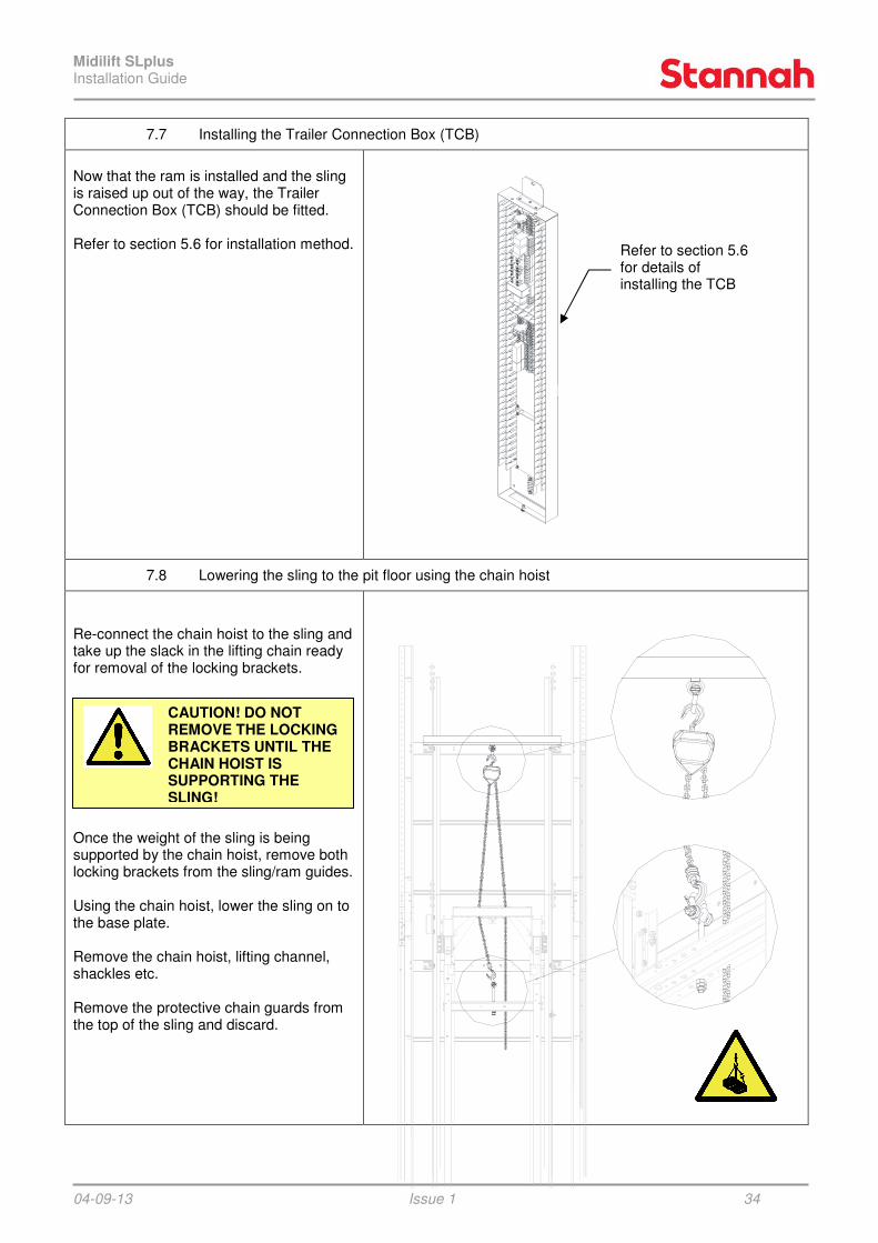
7.7 Installing the Trailer Connection Box (TCB)
Now that the ram is installed and the sling is raised up out of the way, the Trailer Connection Box (TCB) should be fitted. Refer to section 5.6 for installation method.
7.8 Lowering the sling to the pit floor using the chain hoist
Re-connect the chain hoist to the sling and take up the slack in the lifting chain ready for removal of the locking brackets. Once the weight of the sling is being supported by the chain hoist, remove both locking brackets from the sling/ram guides. Using the chain hoist, lower the sling on to the base plate. Remove the chain hoist, lifting channel, shackles etc. Remove the protective chain guards from the top of the sling and discard.
Refer to section 5.6 for details of installing the TCB
CAUTION! DO NOT REMOVE THE LOCKING BRACKETS UNTIL THE CHAIN HOIST IS SUPPORTING THE SLING!

Midilift SLplus Installation Guide
04-09-13 Issue 1 35
8 DOOR INSTALLATION
To prevent people from entering the space below the platform during installation, it is recommended that the lower door is fitted at this stage. Glazed Doors Loosen the fixings on the upper pivot pin and slide it down to its lowest position. Place the door spacer over the pivot hole at the bottom of the door frame. Manoeuvre the door so the lower pivot pin slots through the door spacer and into the bush in the door frame. Line up the upper pivot pin with the pivot hole in the top of the door frame. Slide the upper pivot pin up into the bush in the door frame. Fasten the upper pivot pin by re-tightening the M5 fixings. Clip the curved ‘U’ section to the edge of the door. Fit the handle spigots to the door with the countersunk fixings provided. Fasten the handle to the spigots using the grub screws provided.
Door spacer sits between door & frame
CAUTION: Door assemblies weigh over 70Kg.
Consider using lifting aids before attempting a team lift.
Slide upper pivot pin up into door frame & fasten with M5 fixings
‘U’ section clips to edge of door
NOTE: Once the ‘U’ section has been fitted, it is very difficult to remove without causing damage.
Door handle

Midilift SLplus Installation Guide
04-09-13 Issue 1 36
Fire Doors Before fitting the fire door, the intumescent strips, handle, contacts and door lock plate need to be fitted. A slam plate also needs to be screwed to the slam side edge of the door, but it is best to fit this once the door has been fitted to the frame.
CAUTION: Door assemblies weigh over 70Kg.
Consider using lifting aids before attempting a team lift.
Intumescent strip to be fitted to all 4 edges (self adhesive backing)
Door handle – attached with fixings supplied with the handle
Door slam plate – attached using CSK wood screws
Door contacts – attached using CSK wood screws
Door lock plate – attached using CSK wood screws

Midilift SLplus Installation Guide
04-09-13 Issue 1 37
To fit the fire door, use packers to raise the door to the correct height, then line up the hinges with the holes in the door frame upright. Fix the door to the frame using M5 x 16 stainless steel CSK screws. A 2mm thick shim should be placed between each hinge and the door frame. Note: 1.2mm shims are also provided - these can be used in place of the 2mm shims if the slam edge of the door is tight to the frame. Finally, fix the spacer plates to the slam side of the door frame using self drill csk screws. The plates are used to remove any gaps and increase the fire resistance of the assembly. There should be a 3mm nominal gap on the hinge side. There should be a 5mm nominal gap above and below the door.
To fit door lock fire spacer, remove security screws & refit
Fire door spacers (2 x 3mm & 2 x 1.6mm)
5,0 GAP NOM.
3,0 GAP NOM.
2mm thick shims (nominal)

Midilift SLplus Installation Guide
04-09-13 Issue 1 38
9 CONTROL PANEL & TRAILING CABLE INSTALLATION
9.1 Installing the control panel
Fit the control panel assembly to the sling using 8 off M5x12 flange hex head screws. Feed the trailing cables around the front of the sling upright and secure them using cable ties. Pass the rectangular cut-out of the trailing cable support bracket over the trailing cables and attach the bracket to the bottom right hand side of the sling, using 2 off M5 contact washers and nuts. The trailing cables run behind the support bracket. Attach the trailing cable chain to the support bracket using 2 off M5x16 hex head screws, contact washers and nuts.
Ensure the cables do not protrude more than 15mm in front of the sling upright as this could prevent the cabin side panels from fitting.
Cables must be routed neatly inside the control panel horizontal channel & cable tied to prevent any possibility of them catching on shaftwork items.
Control panel
Trailing cable support bracket
Trailing cable chain
M5x12 flange hex hd screws
Cable ties
M5x16 hex hd screws, contact washers & nuts
Route cables neatly around the back of the control panel horizontal channel & fasten to prevent catching on shaftwork items

Midilift SLplus Installation Guide
04-09-13 Issue 1 39
9.2 Installing the trailing cable chain
The trailing cable fixing channel spans either a horizontal member and ’H’ section or two ‘H’ sections (depending on the lift travel). The fixing channel should be positioned so that the top end of the trailing cable chain is at a height equal to half the lift travel + 200mm. A number of fixing holes are provided in the channel to allow the chain end to be moved up or down to the desired position. Fasten the top end of the trailing cable chain to the fixing channel using 2 off M5x12 flange hex head screws. Cable tie the trailing cables to the fixing channel. Feed the trailing cables over the top of the fixing channel and back down behind it, then fasten the fixing channel to the horizontal member/’H’ section(s) using self drilling screws. Note: The right hand edge of the channel butts up against the corner upright. Ensure that the loop at the bottom of the chain is clear of the base plate.
(Tra
vel ÷ 2
) +
200
(Tra
vel ÷ 2
) +
200
Pit floor
Self drilling screws in to horizontal member / ’H’ section(s) If the bottom landing
entrance is the same side as the trailing cables, the chain loop will hang above the pit stop switch. Ensure sufficient clearance to prevent the chain loop from striking the stop switch!
Check that loop of chain does not hit the base plate or stop switch
Right hand edge of fixing channel butts up against edge of corner upright

Midilift SLplus Installation Guide
04-09-13
9.3 Installing the trailing cable cover and guidance channel
The trailing cables run back down the guide side wall behind a cover and guidance channel assembly and exit in to the guide side horizontal member. On lift travels less than 3.6m one assembly is provided; for travels above 3.6m two assemblies are provided. Measure the distance from the underside of the trailing cable fixing channel to just above the cable access cut-out in the base horizontal member. Cut the cover/guidance channels to lengths that cover this distance. The cut edge should be positioned at the bottom. Fasten the static cables in to the rear of the cover channel using sticky pads and cable ties. This ensures the cables don’t get caught between the channel and the structure wall during fitting. Feed the chain in to the guidance channel(s) and then fasten the channel(s)to the structure wall using self drilling screws. The guidance channel(s) should be vertical and aligned central to the fixing channel.
When the chain is fastened on the upper 3 pairs of holes of the fixing channel, a short length of guidance channel is provided to guide the chain when the lift is at the top floor.
Issue 1
Installing the trailing cable cover and guidance channel
The trailing cables run back down the
in to
On lift travels less than 3.6m one assembly is provided; for travels above 3.6m two
Measure the distance from the underside of the trailing cable fixing channel to just
out in the base . Cut the cover/guidance
Fasten the static cables in to the rear of the cover channel using sticky pads and cable ties. This ensures the cables don’t
caught between the channel and the
the channel(s) to the structure wall using self drilling
should be vertical l to the fixing channel.
Additional guidance channel used when chain
is fixed on any of the 3 upper pairs of holes
(discard if the bottom 3 pairs of holes are used)
When the chain is fastened
holes of the fixing channel, a short length of guidance channel is provided to guide the chain when the lift is at
cover / guidance assembly
(length cut to suit)
40
Self drilling screws
Midilift SLplus Installation Guide
04-09-13 Issue 1 41
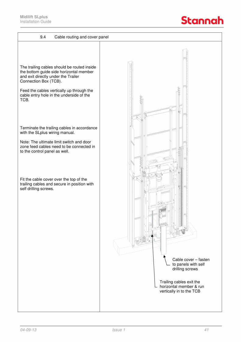
9.4 Cable routing and cover panel
The trailing cables should be routed inside the bottom guide side horizontal member and exit directly under the Trailer Connection Box (TCB). Feed the cables vertically up through the cable entry hole in the underside of the TCB. Terminate the trailing cables in accordance with the SLplus wiring manual. Note: The ultimate limit switch and door zone feed cables need to be connected in to the control panel as well. Fit the cable cover over the top of the trailing cables and secure in position with self drilling screws.
Trailing cables exit the horizontal member & run vertically in to the TCB
Cable cover – fasten to panels with self drilling screws

Midilift SLplus Installation Guide
04-09-13
10 HYDRAULIC PUMP UNIT
10.1 Mounting the pump unit
Position the pump unit as per the builders work drawing. A working area in front of the pump unit must be available – see diagram for minimum dimensions. * For existing buildings the clear height may be reduced to a minimum of 1800mmsuitable warnings must be placed near the pump unit. The pump unit must be fastened in position using the fixings and isolation pads provided. Apply the self adhesive emergency release label to the pump unit.
Issue 1
HYDRAULIC PUMP UNIT
Mounting the pump unit
Position the pump unit as per the builders
the pump unit
height may 800mm but
suitable warnings must be placed near the
The pump unit must be fastened in position
Apply the self adhesive emergency release
Note: Dimensions in mm
Minimum clear working area
Secure pump unit to wall using supplied fixings & isolation pads
Pump unit: empty
42
Note: Dimensions in mm
Minimum clear working area
*
Pump unit: empty ≈ 30kg filled ≈ 60kg
Apply emergency release label

Midilift SLplus Installation Guide
04-09-13
10.2 Connecting the pump unit
Connect the hose to the pump unit and route the hose through the guide side horizontal member to the base of the ram DO NOT CONNECT TO RAM AT THIS STAGE! Run the cable from the pump unit to the trailer connection box and terminate in accordance with the wiring manual. Electrically connect the pump unit to the 240Vac power supply as per the wiring manual. Fill the tank with the correct grade oil, up to the maximum level indicator. Connect the pendant control box and set the controller to installation mode as per the wiring manual. Insert a spare male quick release fitting in the end of the hose and prime the hose by running the pump for a few seconds until clean, air-free oil flows in to a suitable container. Stop the pump and release the male quick release fitting. This process minimises air in the hydraulic system. Connect the quick release coupling to the base of the ram ensuring it is fully engaged. Note: If the coupling fails to engage easily on a 2 stage ram, it could be due to th3mm ram spacer being missing (see section 4.4) or pressure in the hose (decrease pressure by pressing the emergency release button briefly). Any excess hose can be loosely coiled around the motor casing.
NOTE: Ensure hose and cable are routed clear of sling and cabin floor to prevent damage when lift is at the lowest level.
Issue 1
the pump unit
Connect the hose to the pump unit and route the hose through the guide side horizontal member to the base of the ram – DO NOT CONNECT TO RAM AT THIS
Run the cable from the pump unit to the trailer connection box and terminate in
Electrically connect the pump unit to the 240Vac power supply as per the wiring
de oil, up to
ol box and set the controller to installation mode as per
are male quick release fitting in the end of the hose and prime the hose by running the pump for a few seconds until
free oil flows in to a suitable release the
fitting. This process
Connect the quick release coupling to the the ram ensuring it is fully engaged.
Note: If the coupling fails to engage easily on a 2 stage ram, it could be due to the
coiled
Minimum bend radius of 1/2” BSP hose is 70mm
Quick release coupling
Ram
Base plate
NOTE: Ensure hose and cable are routed clear of sling and cabin floor to prevent damage when lift
43
Minimum bend radius of 1/2” BSP hose is 70mm
Hose

Midilift SLplus Installation Guide
04-09-13 Issue 1 44
10.3 Bleeding the ram
Align the hole in the top stage of the ram with the hole in the ram cup. Using the pendant control box, run the pump to drive the ram up in to the ram cup. Insert the retaining bolt and tighten. Run the platform up approximately 250mm. This places the bleed points at easily accessible heights and eliminates the possibility of a shearing hazard. Whilst the descent speed of the platform will be slow and controlled during bleeding of the ram, ensure that limbs are not exposed to a shearing hazard. Particular attention should be given to the shearing potential between sling cross members, the work platform and shaftwork items (such as the ram, its support brackets and TCB). On 3 stage rams the ram guidance channel presents an additional potential shearing hazard with fixed items in the shaft. Locate the bleed points on the ram. 2 stage rams have two bleed points that require a mating bleed nipple and pipe. 3 stage rams have three bleed screws which are opened and closed using a spanner. Note: Sections of the ram which are unguided are able to rotate and so the bleed point may not always be facing forwards. The ram section can be rotated by hand to bring the bleed point to the front. Bleed each section of the ram in turn, until clean, air-free oil flows. Re-close the bleed point each time. If a ram section fully closes before all air is expelled (or the platform comes to rest on it's buffers) the platform should be raised again and the process repeated. Each ram section should have equal extension when bleeding is complete. Once all air is expelled, ensure all bleed points are closed and wipe away any oil residue.
The platform will descend slowly during bleeding – keep all limbs clear of moving parts.
250
Bleed points
Ram retaining bolt
Note: 3 stage ram shown (2 stage ram has only two bleed points)
Ram cup
If attempting to rotate a section of ram whilst the lift is in motion (to access bleed points), pay attention to possible shearing hazards.

Midilift SLplus Installation Guide
04-09-13 Issue 1 45
11 SLING INSTALLATION (CONTINUED)
11.1 Fitting lower sling braces and cross angle
Before fixing the lower sling cross angle and braces, raise the sling up (about 100mm) and rest on packers under each upright. This provides access to fixing bolts on the underside of the floor (needed in the next section). With the sling in the raised position, fix the cross angle in place using M8 (upper) & M5 countersunk (lower) fixings provided. The cross angle should be mounted centrally to the sling. Fasten two (of the four provided) diagonal braces between the sling uprights and the lower cross angle, using M8 fixings. Ensure that the lower end of the brace fixes to the rear face of the sling cross angle. Note: The remaining two diagonal braces are fitted later on when the upper cross angle is fitted.
Lower sling cross angle
Diagonal brace
M8x20 hex hd screw, contact washer & nut
M5 countersunk screw, contact washer & nut
M8x20 hex hd screw, contact washers & nut

Midilift SLplus Installation Guide
04-09-13 Issue 1 46
11.2 Attaching the floor assembly
Before fixing the floor frame in place it is important to check that all safety edges are present and in the correct positions (a safety edge is required on each entrance side). Bolt one side of the floor frame to the lower sling cross angle using M12 fixings. Fasten the lower hitch brackets to the remaining two corners of the floor frame using M12 fixings as shown.
M12x30 hex hd screws, contact washers & nuts
M12x25 hex hd screws & contact washers
Lower hitch bracket
Midilift SLplus Installation Guide
04-09-13 Issue 1 47
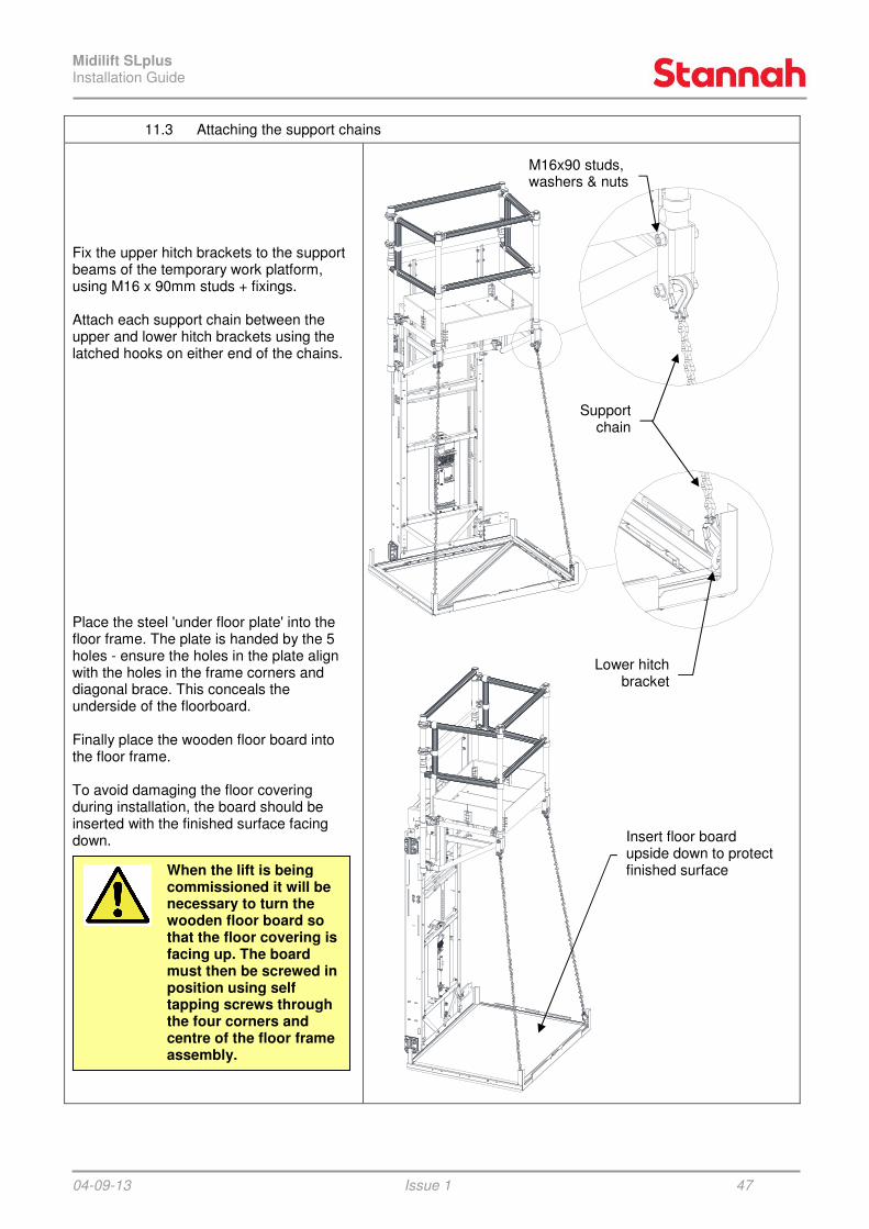
11.3 Attaching the support chains
Fix the upper hitch brackets to the support beams of the temporary work platform, using M16 x 90mm studs + fixings. Attach each support chain between the upper and lower hitch brackets using the latched hooks on either end of the chains. Place the steel 'under floor plate' into the floor frame. The plate is handed by the 5 holes - ensure the holes in the plate align with the holes in the frame corners and diagonal brace. This conceals the underside of the floorboard. Finally place the wooden floor board into the floor frame. To avoid damaging the floor covering during installation, the board should be inserted with the finished surface facing down.
M16x90 studs,
washers & nuts
Lower hitch bracket
Support chain
Insert floor board upside down to protect finished surface When the lift is being
commissioned it will be necessary to turn the wooden floor board so that the floor covering is facing up. The board must then be screwed in position using self tapping screws through the four corners and centre of the floor frame assembly.

Midilift SLplus Installation Guide
04-09-13 Issue 1 48
11.4 Running clearances
Once the sling is in its final position, adjustments need to be made to ensure the sling sits square within the shaft. Add or remove slider packers, on either side of the sling, until there is a gap of approximately 0.5mm between the ‘T’ section guides and the sliders on the sling. Ensure that there isn’t excessive “rocking” of the sling when weight is transferred from one side of the platform to the other.
Guide rail
Sliderpackers
0.5mm
Slider

Midilift SLplus Installation Guide
04-09-13 Issue 1 49
A gap of approximately 27mm should be present between the floor corner brackets and the corner uprights. The gap between the floor safety edge and the corner uprights should be approximately 13mm.
11.5 Guide end stop for installation stage (IMPORTANT HEALTH & SAFETY PROCEDURE)
To ensure that the platform isn’t driven past the end of the guides during installation, the ultimate limit ramp must be positioned 300mm from the top of the car guides and the limit switch tested for correct functioning. DO NOT RELY ON THE ULTIMATE LIMIT SWITCH TO STOP THE PLATFORM - IT IS TO BE REGARDED AS A SAFETY SYSTEM. THE RUN UP BUTTONS SHOULD BE RELEASED PRIOR TO THE ULTIMATE LIMIT RAMP BEING REACHED. As further sections of car guide rail are installed, it will be necessary to move the ultimate limit ramp to the same dimension on the upper car guide rail. Note: In addition, on 3 stage ram arrangements, the ram guides should be built up as high as possible during installation to ensure that the ram guidance assembly does not become driven out of the ram guides.
27
27
13
WARNING! BEFORE ATTEMPTING TO RUN THE PLATFORM THE FOLLOWING SAFETY PROCEDURE MUST BE ADHERED TO!!!
300mm MINIMUM

Midilift SLplus Installation Guide
04-09-13
12 SECURING THE STRUCTURE
12.1 Squaring the structure
As the running clearances of the lift are small, it is vital that the lift is as square as possible to avoid problems at a later stage. On longer travel lifts the guide side will need to be fixed back to a supporting wall as the structure is being built (do NOT wait until the structure is completed before fixing back as it may become unstable). Check builders work drawings for fixing positions. Before fixing back, ensure that the lift is square and vertical using plumb lines, spirit level and measuring the diagonal distancesacross the corner uprights. Jacking brackets Use the jacking brackets provided to aid with squaring the lift, these can be used to push / pull any corner of the structure until square. To fit the jacking brackets: Firstly, ensure access to the outside of the shaft is possible (in the area in which the jacking bolt will be positioned). The best way to achieve this is to fit the jacking brackets before the laminated panels. Feed the jacking bracket into the corner upright (ensure that it has been oriented correctly as it will only feed in one way).
Issue 1
SECURING THE STRUCTURE
Squaring the structure & fixing it to load bearing walls
are square as
at a later stage.
On longer travel lifts the guide side will need to be fixed back to a supporting wall as the structure is being built (do NOT wait
mpleted before fixing back as it may become unstable). Check builders work drawings for fixing positions.
Before fixing back, ensure that the lift is using plumb lines, spirit the diagonal distances
Use the jacking brackets provided to aid with squaring the lift, these can be used to push / pull any corner of the structure until
outside of the shaft is possible (in the area in which the
he best way to achieve this is to fit the jacking brackets before the laminated panels.
Feed the jacking bracket into the corner oriented
correctly as it will only feed in one way).
Jacking bracket
50
Plumb line
Ensure that diagonal distances are equal
Jacking bracket

Midilift SLplus Installation Guide
04-09-13 Issue 1 51
Once in position, temporarily fix in place using M8 fixings into the pre punched holes in the corner upright (the bolts screw into the vertical panel extrusion, through the corner upright). With the bracket fixed in position, mark the position of the threaded hole onto the inside of the corner upright. Remove the bracket and drill a 13.0mm hole. The bracket can then be replaced and a piece of M12 studding can be threaded into the threaded hole in the jacking bracket. Lock two nuts on the end of the M12 studding to enable you to use a spanner to wind the studding in or out. Thread the piece of studding through the corner upright until there is enough visible thread on the outside of the structure to fit the spreader plate. The studding can then be wound in or out to plumb the structure. This process can then be repeated, but with the jacking bracket upside down to give adjustment adjacent to the first fixing. Repeat this for each corner upright. Shaft fixing brackets Use the shaft fixing brackets to fix the guide side of the lift back to a load bearing wall: Use the fixing positions indicated on the builders work drawings to position the fixing brackets. Once in place, use the slot at the back of the bracket to mark the position for a hole onto the laminated panel. Move the bracket and drill a clearance hole
(min n20mm).
Fix the guide side wall into the shaft (load bearing) wall using either chemical fixing of coach bolts. By placing a nut either side of the shaft fixing bracket, the lift can be pushed in or out until plumb.
Mark hole position on inside of corner upright
Note orientation of bracket
Top bracket
Bottom bracket
Bottom bracket (upside down) fixing
Top bracket fixing
Spreader plate
Laminated panel
M12 studding or M10 coach bolt
Fixing substrate
Mesh sleeve (if req’d)
M12 nuts & washers
Car guide rail
Shaft fixing bracket
Midilift SLplus Installation Guide
04-09-13 Issue 1 52
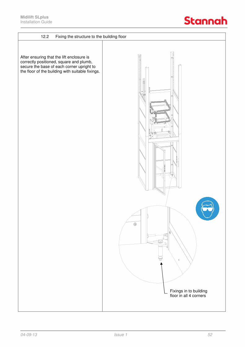
12.2 Fixing the structure to the building floor
After ensuring that the lift enclosure is correctly positioned, square and plumb, secure the base of each corner upright to the floor of the building with suitable fixings.
Fixings in to building floor in all 4 corners

Midilift SLplus Installation Guide
04-09-13 Issue 1 53
13 INTERMEDIATE & UPPER DOOR / FRAME INSTALLATION
13.1 Fitting door frame threshold plate
Assess the need for a threshold plate. If one is required, ensure that it is fixed to the door frame before the door frame is installed. The threshold plate should be positioned so that it is flush with the entrance. The angle on its own will span a gap of up to 20mm, whilst the extended plate can do up to 100mm. In order to fit the angle to the door, remove the lower cover plate and slacken off the three M8 screws (which hold the cross member to the door frame). Slide the infill angle between the cross member and door frame and re-tighten the M8 screws. If a gap greater than 20mm is to be spanned, fix the extended plate to the angle using 4.8mm dome head rivets.
Door infill angle
Door frame
Door frame cross member
Cover plate
Extended door threshold plate
Pop rivets
Door infill angle
Spans up to 20mm gap
Spans from 20 to 100mm gap

Midilift SLplus Installation Guide
04-09-13 Issue 1 54
13.2 Fitting intermediate / upper door frame
Position the door frame so that it sits on top of the cut composite panel, with the door frame threshold level flush with the building finish floor level. Using M8 fixings, fix the door frame in place using the slots provided (see diagram). Note: Some configurations of door frame (shown) require a self drill screw to fix the middle of the hinge side upright to the corner upright.
Lower fixings (M8x20 hex hd screws & contact washers)
Intermediate fixings (M8x20 hex hd screws & contact washers)
Upper fixings (M8x20 hex hd screws, contact washers & nuts)
Intermediate fixings (self drilling screw or M8 fixings – dependant on configuration)
CAUTION: Door Frames weigh 60Kg.
Consider using lifting aids before attempting a team lift.

Midilift SLplus Installation Guide
04-09-13 Issue 1 55
13.3 Fastening door frame to building threshold
Before fixing the structure back to the threshold, firstly check that the lift is square and plumb. Then drill through either the lower cross member of the door frame (shown) or through each door frame side corner upright and into the landing threshold. Using the fixings provided (either chemical fixing or coach bolts), bolt the structure to the landing, placing a nut between the door frame / corner upright and the landing threshold to allow the lift to be jacked in or out. Use a spreader plate on the inside face of the fixing to spread the load over a larger area. These fixings must be repeated at every landing threshold (not including the bottom floor). Note: If there isn’t enough clearance for a nut between the corner upright and the landing threshold, use packers instead. Fit the door following the same procedure as the lower door (refer to section 8).
Corner upright / door frame cross member
Spreader plate
Studding / coach bolt
Use nut either side of corner upright to jack the structure in or out
Washer
Buildingthreshold

Midilift SLplus Installation Guide
04-09-13
14 UPPER STRUCTURE INSTALLATION
14.1 Fitting top corner uprights
The top sections of corner upright are precut in the factory to a length to suit each specific installation. Ensure that the corner uprights are installed the correct way up – the lower end of each corner upright can be identified by four countersunk holes. If the available headroom is greater than 2800mm there will be enough room to install the corner uprights in the same manner as the intermediate uprights. Note: Two different stiffeners are used see illustration for identification & location details.
Issue 1
UPPER STRUCTURE INSTALLATION
Fitting top corner uprights
The top sections of corner upright are pre-cut in the factory to a length to suit each
the lower end of each corner upright can be identified by
If the available headroom is greater than 2800mm there will be enough room to install the corner uprights in the same
Note: Two different stiffeners are used – ation
“Guide side” stiffeners “Opposite guide” stiffeners
56
“Opposite guide” stiffeners
Corner upright
Joint bracket

Midilift SLplus Installation Guide
04-09-13
If the headroom is less than 2800mm it will be necessary to install each corner upright in the following sequence:
a) slide joint bracket in to open end of structure & allow it to rest on the welded gusset
b) insert stiffener in to the top of
corner upright to be fitted & allow it to rest on the welded gusset Note: Two different stiffeners are used – see illustration on previous page for identification & location details
c) position the corner upright above the structure & align it, then slide the joint bracket up in to position and fasten with 8 off M6x25 countersunk screws
d) slide the stiffener up to the top of
the corner upright and temporarily fasten in position with a cable tieNote: The stiffeners will be screwed in place when the upper ring of cross members are installed.
Issue 1
If the headroom is less than 2800mm it will be necessary to install each corner upright
slide joint bracket in to open end of structure & allow it to rest on the
top of the corner upright to be fitted & allow it
Note: Two different stiffeners are
previous for identification & location
position the corner upright above the structure & align it, then slide the joint bracket up in to position
slide the stiffener up to the top of upright and temporarily
fasten in position with a cable tie Note: The stiffeners will be screwed in place when the upper ring of
a)
c)
M6 x 25 csk screws – 8 off
57
b)
d)
Cable tie
Midilift SLplus Installation Guide
04-09-13 Issue 1 58
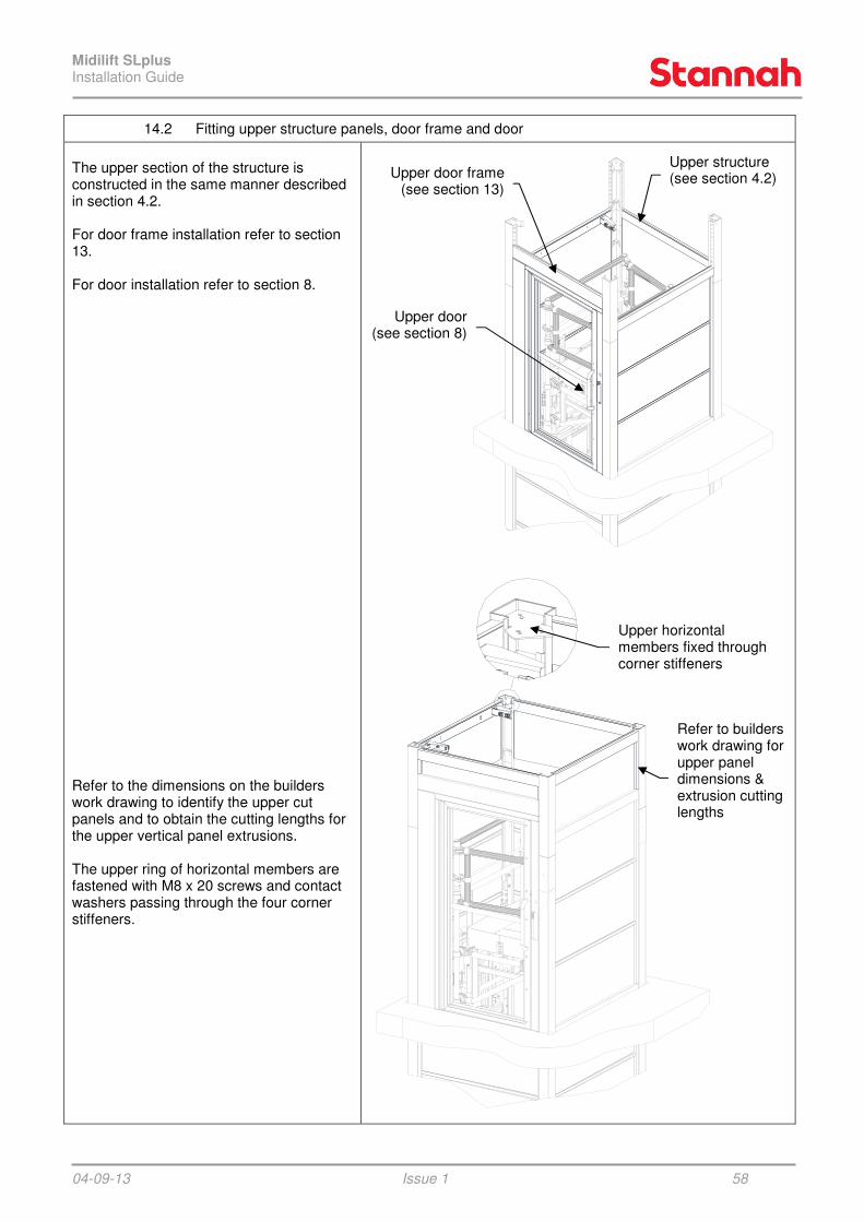
14.2 Fitting upper structure panels, door frame and door
The upper section of the structure is constructed in the same manner described in section 4.2. For door frame installation refer to section 13. For door installation refer to section 8. Refer to the dimensions on the builders work drawing to identify the upper cut panels and to obtain the cutting lengths for the upper vertical panel extrusions. The upper ring of horizontal members are fastened with M8 x 20 screws and contact washers passing through the four corner stiffeners.
Upper structure
(see section 4.2) Upper door frame(see section 13)
Upper door(see section 8)
Upper horizontal members fixed through corner stiffeners
Refer to builders work drawing for upper panel dimensions & extrusion cutting lengths

Midilift SLplus Installation Guide
04-09-13 Issue 1 59
14.3 Installing upper car guides, guide end stops & upper ram guides
Upper car guides The upper car guides are pre-cut in the factory to a length to suit each specific installation and have a hole drilled in the blade near the top of the guide. Using the fishplates provided, attach the upper pair of car ‘T’ section guides. NOTE: ensure the guides are fixed back to the horizontal members using the guide brackets and guide clips.
Fishplates
Fasten upper car guide to top HM using guide bracket and guide clips
Pre-drilled hole (for guide end stops)
Upper car guides
Midilift SLplus Installation Guide
04-09-13 Issue 1 60
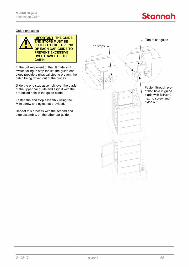
Guide end stops In the unlikely event of the ultimate limit switch failing to stop the lift, the guide end stops provide a physical stop to prevent the cabin being driven out of the guides. Slide the end stop assembly over the blade of the upper car guide and align it with the pre-drilled hole in the guide blade. Fasten the end stop assembly using the M10 screw and nyloc nut provided. Repeat this process with the second end stop assembly, on the other car guide.
IMPORTANT! THE GUIDE END STOPS MUST BE FITTED TO THE TOP END OF EACH CAR GUIDE TO PREVENT EXCESSIVE OVERTRAVEL OF THE CABIN.
End stops
Top of car guide
Fasten through pre-drilled hole in guide blade with M10x40 hex hd screw and nyloc nut

Midilift SLplus Installation Guide
04-09-13 Issue 1 61
Upper ram guides (3 stage rams only) The upper ram guides are pre-cut in the factory to a length to suit each specific installation and each have a pair of holes drilled near the top for fastening back to the upper horizontal member. Attach the upper ram guides to the intermediate ram guide sections using the joiner and fixings provided. The top end of the upper ram guides are fastened directly to the upper horizontal member with a total of four M8 screws and contact washers. Note: A guide joiner is not used at the upper ring level. Ultimate limit switch ramp Once the car guides, ram guides and end stops are in place the ultimate limit switch ramp can be moved up to it's final position. The ramp should be mounted at a height such that the ultimate limit switch operates when the lift is 50mm(+0/-25) above the upper finish floor level.
M8 x 30 hex hd screw
and contact washer
Upper ram guide (pre-cut & drilled in factory to suit
each site)
Ram guide joiner
Upper horizontal member
Upper ram guide
Intermediate ram guide
M8 x 30 hex hd screw and contact washer
Note: A guide joiner is not fitted at the upper HM connection

Midilift SLplus Installation Guide
04-09-13
14.4 Installing the structure ceiling bracing
Structure ceiling bracing The top of the structure must always be fitted with diagonal braces. The braces fasten to each corner upright stiffener using M8x20 hex head screws, contact washers and nuts. A further M8 fixing must be fastened through the hole where the two braces cross in the centre of the structure. If the upper ring of horizontal members are not perfectly square it may be difficult to pass the corner fixings through the holes. Extra holes are provided in the corner upright stiffener and cross braces to allow a podger to be used to lever them in to position. The corner fixings should be fastened in the outermost holes; the innermost holes are for the use of a podger or similar.
Corner fixings fasten holes. Inner holes are provided for insertion
of a podger to make alignment easier.
Issue 1
Installing the structure ceiling bracing
The top of the structure must always be
The braces fasten to each corner upright stiffener using M8x20 hex head screws, contact washers and nuts. A further M8 fixing must be fastened through the hole
in the centre of
If the upper ring of horizontal members are not perfectly square it may be difficult to pass the corner fixings through the holes. Extra holes are provided in the corner upright stiffener and cross braces to allow a
to be used to lever them in to position. The corner fixings should be
innermost holes are for the use of a podger
One ceiling brace fits on top of the corner upright stiffeners, the other brace fits underneath the remaining two stiffeners.
Corner fixings fasten through the outer holes. Inner holes are provided for insertion
of a podger to make alignment easier.
Central fixing passes through the two braces
62
One ceiling brace fits on top of the corner upright stiffeners, the other brace fits underneath the remaining two stiffeners.

Midilift SLplus Installation Guide
04-09-13 Issue 1 63
14.5 Landing call station - standard
Note: The cable looms are cut to specific lengths to suit each call station position. Ensure the correct loom is used at each landing so that it is long enough to route to the trailer connection box. Feed a 12 core cable through the pre-drilled hole in the corner upright and the door frame upright. At landings where a keyswitch is fitted, it is also necessary to run a 2 core cable back to the trailer connection box. Follow the SLplus wiring manual for connecting the call station and lock assembly. Remove end caps to give access to the fixing holes. Fasten the call station body to the door frame upright using M5 tamperproof fixings. Refit the end caps using the M3 socket screws provided.
14.6 Landing call station - fire clad
Fit a back box to the corner upright using two large self drilling screws. Drill a Ø20 hole through the back box and into the corner upright. Fit a rubber grommet and feed the call station cables through. The call station can then be fitted in the same manner as detailed in section 14.5 above. If the cladding has been fitted, drill a Ø25 hole through the cladding, in line with the lock release. Insert the emergency release tube and screw on the bezel.
Call station body
M5x12 tamperproof screws - 2 off
M3x10 socket head screws - 2 off
End caps
Cables fed through corner upright & door
frame
Bezel
Tube
Cladding
Corner upright
Timber battens
Back box
Rubber grommet
Self drilling screws - 2 off
Cladding

Midilift SLplus Installation Guide
04-09-13 Issue 1 64
15 CABIN FRAME INSTALLATION
The cabin frame can now be constructed in the same way as detailed in the XLplus installation manual with the following exceptions:
Optical Proximity Switch (OPS) The SLplus utilises a single Optical Proximity Switch (OPS) to act as a bottom floor reset for the lift positioning system. The OPS assembly and cover panel is mounted on to the top sling cross angle using M5 fixings in to tapped holes. Note: The OPS (and associated guide mounted activation bracket) are located on the opposite side of the sling to the trailing cables.
Load weighing sensor The load weighing sensor for the cabin overload system is mounted on the top edge of the cabin support angle using the M6 fixings supplied. Route the cable around the cabin support beams, down the sling upright and plug it in to the load weighing control box. Ensure the cable is tied back neatly so that it cannot catch on any moving parts when the lift is in motion.
M5x40 hex hd screws
M5 contact washers
M5 tapped holes in top sling cross angle
Cover panel
Optical Proximity Switch (OPS)
Cabin support angle
M6 fixings (provided with sensor)
Load weighing sensor

Midilift SLplus Installation Guide
04-09-13 Issue 1 65
16 INSTALLING THE LIFT POSITIONING ENCODER
The lift positioning encoder system can now be installed in the same way as detailed in the XLplus installation manual with the following exception:
Upper bracket - encoder belt The upper bracket for the encoder belt should be attached just below the highest guide bracket.
17 CABIN INTERIOR INSTALLATION
The cabin interior can now be installed in the same way as detailed in the XLplus installation manual with the following exception:
Place the roof brace diagonally across the two cabin support beams. Fasten the brace in position with two M5 flanged hex head screws in to the tapped holes in the support beams. Note: The folded angle of the roof brace should face downwards so that it does not clash with the structure bracing (when the lift is at its uppermost position).
Upper encoder belt bracket
Clamp plate
Encoder belt
Highest guide bracket
Car guide
M5 tapped hole in cabin support beam
Roof brace (Note: folded angle must point downwards)
M5 flanged hex hd screw

Midilift SLplus Installation Guide
04-09-13 Issue 1 66
18 HYDRAULIC CONTROL VALVES
18.1 Hydraulic control valves - overview
The SLplus is equipped with two solenoid operated down valves: the main down valve (D) and an additional safety valve (DLV) which will hold the lift stationary if the main down valve (D) fails to close for any reason. Each valve has its own independent control signal. Safety control The safety valve (DLV) is a basic valve which is either fully open or fully closed. DLV does not control the speed of the cabin. Speed control The main valve block controls the upwards soft start and stop, the down soft start, rated speed and stop. The unit is pressure compensating to achieve a constant down speed under all load conditions. Rated speed upwards is not adjustable. Valve control sequence To permit a smooth start, it is necessary to open DLV a short time before D. DLV and D are both held open during travel of the lift. To permit a smooth stop, it is necessary to keep DLV open for a short time after D has closed at the end of a down journey. Refer to signal timing sequence on next page for further details. Notes: 1. The valve block has two manual lowering valves fitted. The manual lowering valve nearest to the front of the pump unit is redundant on this system (due to L10 being normally closed). Manual lowering must therefore be achieved by operating the lowering valve located towards the rear of the pump unit. 2. No pressure switches are fitted to the valve block; load weighing is achieved using a load cell mounted on the sling. 3. In the event of D failing to close at the end of a down journey the lift will descend at rated speed away from the floor level for 1.5 secs until DLV closes and brings the lift to rest. At the lowest landing the cabin will rest on its buffers
Door lock valve (DLV) Blain L10 1/2"
Main valve block Blain KV1P
Pressure gauge
DLV, Safety down solenoid
D, Down solenoid
Oil filler cap
Main shut off valve
Emergency lowering valve, H
Valve 1 Up start
Valve 9 Down speed
Valve 6 Down acc.
Pressure relief, S Pressure gauge shut off
Manual lowering valve (redundant due to L10)
SLplus valve block

Midilift SLplus Installation Guide
04-09-13
18.2 Hydraulic control valves
Adjustments UP The valves have already been set, but some on site adjustment may be required.Up Bypass: When the pump is started, the unloaded platform should remain stationary at the floor for a period of about 1 second before starting upwards. The length of this delay is according to the setting of adjustment (clockwise) shortens the delay, 'out' (anticlockwise) lengthens the delay. Up Stop: At floor level, the pump-motor is deenergized. The stop may be abrupt depending on load and speed of approach. No adjustment possible. S, Relief Valve: 'In' (clockwise) produces a higher, 'out' (anti-clockwise) a lower maximum pressure setting. After turning 'out', open manual lowering H for an instant to decrease pressure before re-checking. Important: When testing relief valve, do not close main shut off valve sharply.
Adjustments DOWN The valves have already been set, but some on site adjustment may be required.Check electrical operation before changing valves settings. Down Acceleration: Solenoid DLV is energised 1.5 secs before solenoid D. During this period the lift is held stationary by D. When solenoid D is energized, the car will accelerate downwards according to the setting of adjustment 6. 'In' (clockwise) provides a softer down acceleration, 'out' (anti-clockwise) a quicker acceleration. Pre-adjustment: 6 should be turned all the way in and then solenoid energized. Turn 6 slowly back out until the car accelerates downwards. Down Speed: With solenoids DLV and energized as above, the down speed of the platform is according to the setting of adjustment 9. 'In' (clockwise) provides a slower down speed, 'out' (anti-clockwise) a faster down speed. Down Stop: At floor level, solenoid D energized causing the car to stop. No adjustment necessary. 1.5 secs after solenoid D is de-energised, DLV is de-energised.H, Emergency lowering valve: 'out' (anticlockwise) allows the car to be lowered by hand. Closes automatically on release. KS: Some units may be fitted with a slack rope valve. This is not required on the Midilift but may still need to be adjusted. If an eplatform will not descend when DLV and D are both energised, turn KS anti-clockwise until the platform starts to move, turn another half turn to allow for cold conditions.
Issue 1
Hydraulic control valves - adjustment
, but some on site adjustment may be required.
When the pump is started, the unloaded platform should remain stationary at the floor for a period of about 1 second before starting upwards. The length of this delay is according to the setting of adjustment 1 'In'
(anti-
motor is de-energized. The stop may be abrupt depending
'In' (clockwise) produces a e) a lower maximum
pressure setting. After turning 'out', open for an instant to decrease
Important: When testing relief valve, do not
, but some on site adjustment may be required. Check electrical operation before changing
Solenoid DLV is energised 1.5 secs before solenoid D. During this period the lift is held stationary by D.
is energized, the car will accelerate downwards according to the setting
'In' (clockwise) provides a softer down clockwise) a quicker
should be turned all the way in and then solenoid D
slowly back out until the car
and D the down speed of the
platform is according to the setting of 'In' (clockwise) provides a
clockwise) a
is de-energized causing the car to stop. No
1.5 secs after solenoid energised.
'out' (anti-clockwise) allows the car to be lowered by hand. Closes automatically on release.
: Some units may be fitted with a slack This is not required on the Midilift
but may still need to be adjusted. If an empty platform will not descend when DLV and D are
clockwise until the platform starts to move, turn another half
H, Emergency lowering valve
Valve 9
Valve 6 (3mm hex key)
S, Pressure relief
DLV
KS (only flocated between redundant lowering valve and pressure gauge shut off
SLplus timing sequence
= energised
Key:
Running up
Running down
Speed
Tim
e
67
Valve 1
Valve 9
(3mm hex key)
DLV
1.5
secs
1.5
secs
D
only fitted on some units: located between redundant lowering valve and pressure gauge shut off )
SLplus timing sequence
Running down

Midilift SLplus Installation Guide
04-09-13 Issue 1 68
Problem Possible fault Possible solution
• Specific fault code displayed on DDU's
• Codes A to F and R • Refer to 'Fault Code List' in
SLplus wiring manual
• No Power
• Loss of power to the building • Contact electricity supplier
• Circuit breaker (MCB) tripped
• Reset MCB
• Isolation keyswitch turned off • Turn isolation keyswitch (3
position) to 'ON' position
• No Movement
• Both Directions
• Safety chain broken
• Identify point at which safety chain is broken, identify problem, reset safety switch and re-test.
• Door not closed • Close all doors & ensure all
locks are fully engaged
• Cabin safety edge operated/sticking
• Remove obstruction/
• Light ray activated • Clear obstruction
• Motor thermal overload tripped
• Reset overload (located on terminal box inside pump unit)
• Main shut off valve closed • Re-open main shut off valve
• Ultimate limit switch activated
• Lower lift with manual lowering valve, adjust ramp position & reset switch
• Lift overloaded
• Remove excess load
• Reset overload limit on LCA controller (located on the sling)
• Isolation keyswitch turned off • Turn keyswitch on
• Up only • Pump running but will not
raise cabin
• Check for excess payload
• Adjust relief valve if necessary
• Main down valve (D) energised - check feed to D
• Main down valve stuck open - check for contamination or replace D
• Down only
• No signal voltage applied to down solenoids
• Check 24V is being applied to DLV and/or D (see timing sequence on previous page)
• Rupture valve operated
• Check system is working correctly. Raise lift to release rupture valve. Adjust setting if necessary.
• Poor ride quality
• Damaged guides • Identify damaged area of
guides and file flat.
• Rough guide joints • Identify rough guide joint and
file flat.
• Poor start, acceleration or stopping
• Refer to valve adjustments on previous page
19 TROUBLE SHOOTING

Midilift SLplus Installation Guide
04-09-13 Issue 1 69
• Lift stops outside floor level tolerance (±10mm) / Ultimate limit activated
• Floor levels incorrectly set up
• Re-teach floor levels
• Journey timer tripped
• Check setting of bit switch 2 (on pcb on cabin mounted control panel): Off=30secs, ON=60secs
• Timing belt pulley not connected to encoder shaft
• Tighten the grub screw locking the timing belt to the encoder shaft (located on the encoder assembly – rear of the cabin
• Encoder shaft not connected to the encoder
• Tighten the grub screw locking the encoder to the encoder shaft (located on the encoder assembly – rear of the cabin
• Lift sinks below floor level over time
• Anti-creep not operating correctly
• Refer to wiring manual
• Door will not open/unlock
• Lift not in door zone. Door zone switch not activated.
• Adjust door zone ramp position.
• No solenoid feed (SF) at door zone switch
• Refer to wiring manual
• Structure creaking • Lift not fixed back correctly /
adequately
• Refer to builders work drawing, adjust / add structure fixings
* Refer to diagrams overleaf
20 Safety chain switch locations
Designation Description Location *
G1 Shutdown keyswitch Main entrance landing station
G2 Pit stop and pit prop switches Mounted on the base plate assembly in the pit
G3 Ultimate limit switch Mounted on the outside of one sling upright
G4 Carriage stop switch Mounted on the COP within the cabin
G5 Landing door beak contacts Between the landing door and frame (at each landing)
G6 Solenoid lock switches Mounted on each solenoid lock (at each landing)
G7 Solenoid feed monitor G7 terminal can be found on carriage control PCB
G7A Anti-creep relay Located in the trailer connection box
G7B Cabin floor safety edge Mounted on the entrance side of the floor assembly
G7C Cabin roof safety edge Mounted on the entrance side of the roof assembly
G7D Ceiling beak contacts Mounted on the lock side of the ceiling
G8 Roof stop switch Mounted on top of the guide side of the sling

Midilift SLplus Installation Guide
04-09-13 Issue 1 70
G3
G2
G8
G7A
Pit prop
Trailer connection
box
Encoder
Cabin control
box
Door zone
switch
Down stop OPS
Upper guide stops
Ram retaining
bolt
G4
G7D
G7C
G7B
G6
G1
G5
Shaftwork switches & components Door & call station switches
Cabin switches
Midilift SLplus Installation Guide
04-09-13 Issue 1 71
21 Commissioning
Commissioning test On completion of the installation the lift is ready to be tested. The test must be carried out according to the 'Midilift test and handover document'. The lift can only be commissioned once this has been correctly completed. Uncontrolled movement test The correct operation of the safety valve (DLV) must be verified as part of the commissioning process. To check the operation: a) Remove the two 19mm AF lock nuts from the solenoid stems b) Call the lift downwards. c) While the lift is descending, briefly lift the coil off of the main down valve (D) - the lift should stop immediately. d) Quickly replace the coil so that the lift descends again. e) Repeat steps (a) to (d) with the coil from the safety valve (DLV) - again the lift should stop immediately. IF THE LIFT FAILS TO STOP IMMEDIATELY WHEN EITHER OF THE COILS ARE LIFTED, THE VALVE IS FAULTY AND CORRECTIVE ACTION MUST BE TAKEN BEFORE THE LIFT CAN BE HANDED OVER. Note: If the lift is stationary for more than 4 seconds during a down journey an encoder fault 'FA' will occur. Do not leave the coils off the valve stems for more than a few seconds as they can overheat and become damaged. Cleaning Before handing the lift over to the customer, ensure the work place is tidy and the lift is clean. The cabin interior and the inside/outside of the structure will need to be cleaned. To access the inside of the shaft for cleaning, the ceiling can be dropped and the roof centre board removed - by using a step ladder in the cabin, the inside of the structure can then be accessed. To run the lift with the ceiling open it will be necessary to use the pendant controller with a shorting link placed between G7C and G8 of the safety circuit - ENSURE THIS LINK IS REMOVED BEFORE HANDOVER. Demonstration When handing the lift over to the customer or the person responsible for the lift, the following must be demonstrated to him/her: i. Full operation of the lift controls. ii. The position and operation of all safety edges and surfaces. iii. The lift manual lowering procedure and the passenger release procedure. iv. Ensure the customer is aware of who to contact in case of a break down. Before leaving the site you must ensure the customer has run through a complete operation of the lift and is completely satisfied with the product.
DO NOT RUN THE LIFT WHILE AN ENGINEER IS USING THE CEILING ACCESS HATCH TO CLEAN THE LIFT SHAFT - THE ENGINEER MUST ALWAYS RETURN TO THE INSIDE OF THE CABIN BEFORE RAISING OR LOWERING THE LIFT.

Midilift SLplus Installation Guide
04-09-13 Issue 1 72
22 Document History
Issue Name Changes Date
Issue 1 R Christopher First issue 04/09/13