
middlefield middlefield middlefield may be required. start here empezar aquí commencez ici Mounting...
3
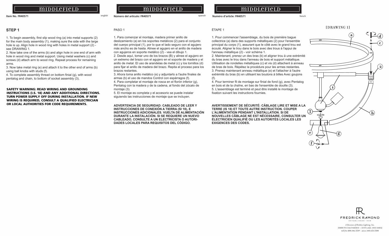
Item No. FR40571 Numéro d’article: FR40571 Número del artículo: FR40571 english spanish french middlefield middlefield middlefield SAFETY WARNING: READ WIRING AND GROUNDING INSTRUCTIONS (I.S. 18) AND ANY ADDITIONAL DIRECTIONS. TURN POWER SUPPLY OFF DURING INSTALLATION. IF NEW WIRING IS REQUIRED, CONSULT A QUALIFIED ELECTRICIAN OR LOCAL AUTHORITIES FOR CODE REQUIREMENTS. STEP 1 1. To begin assembly, first slip wood ring (a) into metal supports (2) for the main body assembly (1), making sure the side with the large hole is up. Align hole in wood ring with holes in metal support (2) - see DRAWING 1. 2. Now take one of the arms (b) and align hole in one end of arm with hole in wood ring and metal support. Using metal washers (c) and screws (d) attach arm to wood ring. Repeat process for remaining arms. 3. Now take metal ring (e) and attach it to the other end of arms (b) using ball knobs with studs (f). 4. To complete assembly thread on bottom finial (g), with wood pentalog and chain, to bottom of socket assembly (3). [DRAWING 1] 1 a c 2 1 b d e f g 3 PASO 1 1. Para comenzar el montaje, madera primer anillo de deslizamiento (a) en los soportes metálicos (2) para el conjunto del cuerpo principal (1), por lo que el lado seguro con el agujero más ancho es de hasta. Alinee el agujero en el anillo de madera con agujeros en soporte metálico (2) - vea el dibujo 1. 2. Desde aquí, tomar uno de los brazos (B) y alinee el agujero en un extremo del brazo con el agujero en el soporte de madera y el anillo de metal. El uso de arandelas de metal (c) y los tornillos (d) para fijar el anillo de madera del brazo. Repita el proceso para los brazos restantes. 3. Ahora toma anillo metálico (e) y adjuntarlo a l'autre finales de armas (b) el uso de mandos Control con espárragos (f). 4. Para completar el montaje de rosca en el florón inferior (g), Pentalog con la madera y de la cadena, al fondo del zócalo de montaje (3). 5. El montaje es completa y el accesorio se puede instalar siguiendo las instrucciones de montaje que se incluyen. ÉTAPE 1 1. Pour commencer l'assemblage, du bois de première bague collectrice (a) dans des supports métalliques (2) pour l'ensemble principal du corps (1), assurant que le côté avec le grand trou est écoulé. Aligner le trou dans le bois avec des trous à l'appui de l'anneau métallique (2) - voir schéma 1. 2. Maintenant, prenez un des bras (b) et aligner trou à une extrémité du bras avec le trou dans l'anneau de bois et support métallique. Utilisation de rondelles métalliques (c) et vis (d) attachent à anneau de bras de bois. Répétez la procédure pour les armes restantes. 3. Prenez maintenant anneau métallique (e) et l'attacher à l'autre extrémité du bras (b) en utilisant les boutons à billes Avec goujons (f). 4. Pour terminer fil de montage sur finial de fond (g), avec Pentalog en bois et de la chaîne, en bas de l'ensemble de douille (3). 5. L'assemblage est terminé et peut être installé le montage de fixation suivant les instructions fournies. ADVERTENCIA DE SEGURIDAD: CABLEADO DE LEER Y INSTRUCCIONES DE CONEXIÓN A TIERRA (SI 18), E INSTRUCCIONES ADICIONALES. VUELTA DE ALIMENTACIÓN DURANTE LA INSTALACIÓN. SI SE REQUIERE UN NUEVO CABLEADO, CONSULTE A UN ELECTRICISTA O AUTORI- DADES LOCALES PARA REQUISITOS DEL CÓDIGO. AVERTISSEMENT DE SÉCURITÉ: CÂBLAGE LIRE ET MISE A LA TERRE (IS 18) ET TOUTE AUTRE INSTRUCTION. COUPER L'ALIMENTATION PENDANT L'INSTALLATION. SI DE NOUVELLES CÂBLAGE NE EST NÉCESSAIRE, CONSULTER UN ÉLECTRICIEN QUALIFIÉ OU LES AUTORITÉS LOCALES LES EXIGENCES DES CODES.
-
Upload
vuongthuan -
Category
Documents
-
view
229 -
download
0
Transcript of middlefield middlefield middlefield may be required. start here empezar aquí commencez ici Mounting...
Item No. FR40571 Numéro d’article: FR40571 Número del artículo: FR40571english spanish french
middlefield middlefield middlefield
SAFETY WARNING: READ WIRING AND GROUNDING INSTRUCTIONS (I.S. 18) AND ANY ADDITIONAL DIRECTIONS. TURN POWER SUPPLY OFF DURING INSTALLATION. IF NEW WIRING IS REQUIRED, CONSULT A QUALIFIED ELECTRICIAN OR LOCAL AUTHORITIES FOR CODE REQUIREMENTS.
STEP 1
1. To begin assembly, first slip wood ring (a) into metal supports (2) for the main body assembly (1), making sure the side with the large hole is up. Align hole in wood ring with holes in metal support (2) - see DRAWING 1.2. Now take one of the arms (b) and align hole in one end of arm with hole in wood ring and metal support. Using metal washers (c) and screws (d) attach arm to wood ring. Repeat process for remaining arms.3. Now take metal ring (e) and attach it to the other end of arms (b) using ball knobs with studs (f).4. To complete assembly thread on bottom finial (g), with wood pentalog and chain, to bottom of socket assembly (3).
[DRAWING 1]
1
a
c
2
1
b
d
e
f
g
3
PASO 1
1. Para comenzar el montaje, madera primer anillo de deslizamiento (a) en los soportes metálicos (2) para el conjunto del cuerpo principal (1), por lo que el lado seguro con el agujero más ancho es de hasta. Alinee el agujero en el anillo de madera con agujeros en soporte metálico (2) - vea el dibujo 1.2. Desde aquí, tomar uno de los brazos (B) y alinee el agujero en un extremo del brazo con el agujero en el soporte de madera y el anillo de metal. El uso de arandelas de metal (c) y los tornillos (d) para fijar el anillo de madera del brazo. Repita el proceso para los brazos restantes.3. Ahora toma anillo metálico (e) y adjuntarlo a l'autre finales de armas (b) el uso de mandos Control con espárragos (f).4. Para completar el montaje de rosca en el florón inferior (g), Pentalog con la madera y de la cadena, al fondo del zócalo de montaje (3).5. El montaje es completa y el accesorio se puede instalar siguiendo las instrucciones de montaje que se incluyen.
ÉTAPE 1
1. Pour commencer l'assemblage, du bois de première bague collectrice (a) dans des supports métalliques (2) pour l'ensemble principal du corps (1), assurant que le côté avec le grand trou est écoulé. Aligner le trou dans le bois avec des trous à l'appui de l'anneau métallique (2) - voir schéma 1.2. Maintenant, prenez un des bras (b) et aligner trou à une extrémité du bras avec le trou dans l'anneau de bois et support métallique. Utilisation de rondelles métalliques (c) et vis (d) attachent à anneau de bras de bois. Répétez la procédure pour les armes restantes.3. Prenez maintenant anneau métallique (e) et l'attacher à l'autre extrémité du bras (b) en utilisant les boutons à billes Avec goujons (f).4. Pour terminer fil de montage sur finial de fond (g), avec Pentalog en bois et de la chaîne, en bas de l'ensemble de douille (3).5. L'assemblage est terminé et peut être installé le montage de fixation suivant les instructions fournies.
ADVERTENCIA DE SEGURIDAD: CABLEADO DE LEER Y INSTRUCCIONES DE CONEXIÓN A TIERRA (SI 18), E INSTRUCCIONES ADICIONALES. VUELTA DE ALIMENTACIÓN DURANTE LA INSTALACIÓN. SI SE REQUIERE UN NUEVO CABLEADO, CONSULTE A UN ELECTRICISTA O AUTORI-DADES LOCALES PARA REQUISITOS DEL CÓDIGO.
AVERTISSEMENT DE SÉCURITÉ: CÂBLAGE LIRE ET MISE A LA TERRE (IS 18) ET TOUTE AUTRE INSTRUCTION. COUPER L'ALIMENTATION PENDANT L'INSTALLATION. SI DE NOUVELLES CÂBLAGE NE EST NÉCESSAIRE, CONSULTER UN ÉLECTRICIEN QUALIFIÉ OU LES AUTORITÉS LOCALES LES EXIGENCES DES CODES.
start here commencez ici empezar aquí
Mounting Instructions
Item No: 40571
Instructions de montage
Numéro d’article: 40571
Instrucciones De Montaje
Número del artículo: 40571English Spanish French
1. Find a clear area in which you can work.2. Unpack fixture and glass from carton.3. Carefully review instructions prior to assembly.
1. Encontrar un área clara en la que se puede trabajar. 2. Desembale xture fi y el vidrio de la caja. 3. Revise cuidadosamente las instrucciones antes del montaje.
1. Trouvez un endroit clair dans lequel vous pouvez travailler.2. Déballez fi xture et de verre du carton.3. Examinez attentivement les instructions avant l'assemblage.
SAFETY WARNING: READ WIRING AND GROUNDING INSTRUC-TIONS (I.S. 18) AND ANY ADDITIONAL DIRECTIONS. TURN POWER SUPPLY OFF DURING INSTALLATION. IF NEW WIRING IS REQUIRED, CONSULT A QUALIFIED ELECTRICIAN OR LOCAL AUTHORITIES FOR CODE REQUIREMENTS.
Make electrical connections from supply wire to fixture lead wires. Refer to instruction sheet (I.S. 18) and follow all instructions to make all necessary wiring connections. Then refer back to this sheet to complete installation of this fixture.
ADVERTENCIA DE SEGURIDAD: CABLEADO DE LEER Y INSTRUCCIONES DE CONEXIÓN A TIERRA (SI 18), E INSTRUCCIONES ADICIONALES. VUELTA DE ALIMENTACIÓN DURANTE LA INSTALACIÓN. SI SE REQUIERE UN NUEVO CABLEADO, CONSULTE A UN ELECTRICISTA O AUTORI-DADES LOCALES PARA REQUISITOS DEL CÓDIGO.
AVERTISSEMENT DE SÉCURITÉ: CÂBLAGE LIRE ET MISE A LA TERRE (IS 18) ET TOUTE AUTRE INSTRUCTION. COUPER L'ALIMENTATION PENDANT L'INSTALLATION. SI DE NOUVELLES CÂBLAGE NE EST NÉCESSAIRE, CONSULTER UN ÉLECTRICIEN QUALIFIÉ OU LES AUTORITÉS LOCALES LES EXIGENCES DES CODES.
Haga las conexiones eléctricas del cable para suministrar cables conductores de luz. Consulte la hoja de instrucciones (IS 18) y siga todas las instrucciones para hacer todas las conexiones necesar-ias. Luego vuelva a esta hoja para completar la instalación de este accesorio.
Faire les raccordements électriques des fils fils conducteurs d'alimentation du luminaire. Reportez-vous à la fiche d'instruction (IS 18) et suivez toutes les instructions de faire tous les raccordements nécessaires. Puis revenez consulter cette fiche pour terminer l'installation de este luminaire.
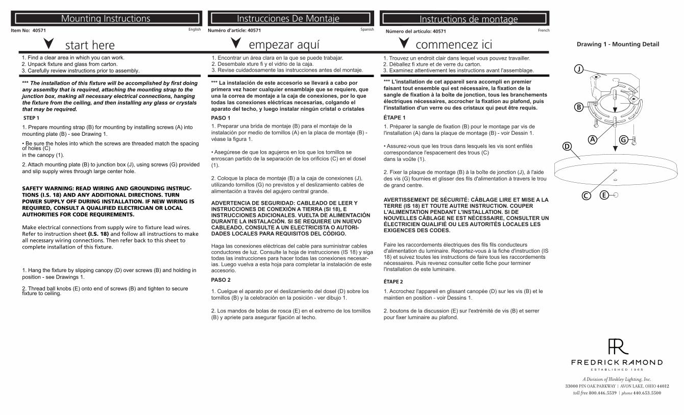
Drawing 1 - Mounting Detail
J
B
A G
EC
D
*** The installation of this fixture will be accomplished by first doing any assemlby that is required, attaching the mounting strap to the junction box, making all necessary electrical connections, hanging the fixture from the ceiling, and then installing any glass or crystals that may be required.
1. Prepare mounting strap (B) for mounting by installing screws (A) into mounting plate (B) - see Drawing 1.
• Be sure the holes into which the screws are threaded match the spacing of holes (C)in the canopy (1).
2. Attach mounting plate (B) to junction box (J), using screws (G) provided and slip supply wires through large center hole.
1. Hang the fixture by slipping canopy (D) over screws (B) and holding in position - see Drawings 1.
2. Thread ball knobs (E) onto end of screws (B) and tighten to secure fixture to ceiling.
1. Preparar una brida de montaje (B) para el montaje de la instalación por medio de tornillos (A) en la placa de montaje (B) - véase la figura 1.
• Asegúrese de que los agujeros en los que los tornillos se enroscan partido de la separación de los orificios (C) en el dosel (1).
2. Coloque la placa de montaje (B) a la caja de conexiones (J), utilizando tornillos (G) no previstos y el deslizamiento cables de alimentación a través del agujero central grande.
*** La instalación de este accesorio se llevará a cabo por primera vez hacer cualquier ensamblaje que se requiere, que una la correa de montaje a la caja de conexiones, por lo que todas las conexiones eléctricas necesarias, colgando el aparato del techo, y luego instalar ningún cristal o cristales
*** L'installation de cet appareil sera accompli en premier faisant tout ensemble qui est nécessaire, la fixation de la sangle de fixation à la boîte de jonction, tous les branchements électriques nécessaires, accrocher la fixation au plafond, puis l'installation d'un verre ou des cristaux qui peut être requis.
1. Préparer la sangle de fixation (B) pour le montage par vis de l'installation (A) dans la plaque de montage (B) - voir Dessin 1.
• Assurez-vous que les trous dans lesquels les vis sont enfilés correspondance l'espacement des trous (C)dans la voûte (1).
2. Fixer la plaque de montage (B) à la boîte de jonction (J), à l'aide des vis (G) fournies et glisser des fils d'alimentation à travers le trou de grand centre.
1. Cuelgue el aparato por el deslizamiento del dosel (D) sobre los tornillos (B) y la celebración en la posición - ver dibujo 1.
2. Los mandos de bolas de rosca (E) en el extremo de los tornillos (B) y apriete para asegurar fijación al techo.
1. Accrochez l'appareil en glissant canopée (D) sur les vis (B) et le maintien en position - voir Dessins 1.
2. boutons de la discussion (E) sur l'extrémité de vis (B) et serrer pour fixer luminaire au plafond.
PASO 1
PASO 2
ÉTAPE 1
ÉTAPE 2
STEP 1
FRIS18
TIERRA CABLEADO INSTRUCCIONES
Advertencia De Seguridad: Lea las Instrucciones de cableado y conexión a tierra [FRIS 18], e instrucciones adicionales. Encienda la alimentación de corriente durante la instalación. Si se necesita un nuevo cable, consulte a un electricista calificado o con las autoridades locales de los requisitos del código.
PASO 1 INSTRUCCIONES DE CABLEADO
Accesorios Cubierta
1. Conecte el cable de alimentación positive (A) (normalmente negro o la cara lisa, sin marcas del ceable de dos conductores) de plomo accesorio positivo (B) con un giro de tamaño adecuado en el conector – Véase la Figura 1 o 2.
2. Conecte el cable de alimentación negative (C) (por lo general de color blanco o el lado marcado estriado del cable de dos conductores) de plomo accesorio negativo (D).
3. Por favor, consulte las Instrucciones de conexión a tierra de abajo para completer todas las conexiones eléctricas.
Accesorios Exterior
1. Conecte el cable de alimentactión positive (A) (normalmente negro o la cara lisa, sin marcas del cable de dos conductores) de plomo accesorio positivo (B) con un giro de tamanño adecuado en el conector - Véase la Figura 1 o 2.
2. Conectar el cable de alimentación negative (C) (por lo general de color blanco o el, lado marcado acanalada del cable de dos conductores) a plomo acesorio negativo (D).
3. Cubra el extreme abierto de conectores con sellador de silicona para formar un sello hermético.
• Si va a instalar un soporte de fijación mural, use masilla para sellar los espacios entre la placa de montaje del aparato (placa) y la pared. Esto ayudará a evitar que el agua entre en la caja de salida. Si la superficie de la pared es de revestimeinto solapado, utilice masilla y una plataforma de montaje accesorio espacial.
4. Por favor, consulte las Instrucciones de conexión a tierra a continuación para completer todas las conexiones eléctricas.
PASO 2 INSTRUCCIONES PUESTA A TIERRA
FRIS18
CÂBLAGE ÉCHOUAGE INSTRUCTIONS
Avertissement De Sécurité: Lire câblage et de mise à la terre instructions [FRIS 18] et les instructions supplémentaires. Couper l’alimentation électrique pendant l’installation. Si un nouveau câblage nést nécessaire, consultez un ékectricien qualifié ou les autorités locales pour connaître les exigences du code.
ETAPE 1 INSTRUCTIONS DE CÂBLAGE
Luminaires Itérieurs
1. Branchez le câble d’alimentation positive (A) (généralement noir ou, côté lisse banalisée de la corde à deux conducteurs) au plomb de fixation positive (B) avec la torsion de taille appropriée sur le connecteur - Voir Schéma 1 et 2
2. Raccorder le fil d’alimentation negative (C) (généralement blanc ou l’, côté marqué nervurée du fil à deux conducteurs) au conducteur négatif de l’appareil (D).
3. S’il vous plait se referrer aux instructions ci-dessous pour remplir la terre toutes les connexions électriques.
Luminaires Extérieurs
1. Brancher le fil d’alimentation positive (A) (généralement noir ou, côté lisse banalisée de la corde à deux conducteur) à plomb de fixation positive (B) avec la torsion de taille appropriée sur le connecteur – Voir Schéma 1 ou 2.
2. Connecter le fil d’alimentation negative (C) (généralement blanc ou l’, côté marqué nervurée du fil à deux conducteurs) au conducteur négatif de l’appareil (D).
3. Couvrir extrémité ouberte de connecteurs avec du silicone pour former un joint étanche à l’eau.
• Se l’installation d’un luminaire de montage mural, utiliser calfeautrage pour sceller l’espace entre la plaque de montage de fixation (plaque arrière) et la paroi. Cela aidera à emp6echer l’eau de pénétrer dans la boîte de sortie. Si la surface du mur est bardage à clin, utiliser calfeautrage et une plate-forme de montage d’appareils spécialement.
4. S’il vous plait se referrer aux instructions ci-dessous pour terminer la terre toutes les connexions électriques.
ETAPE 2 INSTRUCTIONS DE MISE
Montage Encastré Fixtures Pour la terre positive dans un système électrique à 3 fils, fixez le fil de terre du
luminaire (E) (généralement en cuivre ou vert recouvert de plastique) à la sangle de fixation de fixation (1) avec la vis de terre (2) – Voir Schéma 1.
Remarque: Sur les sangles pour les appareils pris en charge à vis, installez d’abord les deux vis de fixation à sangle.
Tout trou taraudé restante peut être utilisée pour la vis de terre.
Chaîne Accroché Luminaires Boucle fil du luminaire au sol (E) (généralement en cuivre ou vert recouvert de
plastique) sous la tête de la vis de terre (2) sur la sangle de fixation de fixation (1) et se connecter à l’extrémité libre du fil de terre du luminaire directement sur le fil de terre du système de construction avec une taille appropriée connecteurs à visser - Voir Schéma 2.
Luminaires Aprés Montage Brancher le fil de terre du luminaire (E) (généralement en cuivre ou vert
recouvert de plastique) à la masse de l’alimentation avec une taille appropriée torsion sur le conecteur à l’intérieur de la poste. Couvrir extrémité ouverte du connecteur avec du mastic silicone pour former un joint ètache à l’eau – Voir Schéma 3.
FRIS18
WIRING AND GROUNDING INSTRUCTIONS
Safety Warning: Read wiring and grounding instructions [FRIS 18] and any additional directions. Turn power supply off during installation. If new wiring is required, consult a qualified electrician or local authorities for code requirements. STEP 1 WIRING INSTRUCTIONS
Indoor Fixtures
1. Connect positive supply wire (A) (typically black or the smooth, unmarked side of the two-conductor cord) to positive fixture lead (B) with appropriately sized twist on connector – See Drawing 1 or 2.
2. Connect negative supply wire (C) (typically white or the ribbed, marked side of the two-conductor cord) to negative fixture lead (D)
3. Please refer to the grounding instructions below to complete all electrical connections.
Outdoor Fixtures
1. Connect positive supply wire (A) (typically black or the smooth, unmarked side of the two-conductor cord) to positive fixture lead (B) with appropriately sized twist on connector – See Drawing 1 or 2.
2. Connect negative supply wire (C) (typically white or the ribbed, marked side of the two-conductor cord) to negative fixture lead (D)
3. Cover open end of connectors with silicone sealant to form a watertight seal. • If installing a wall mount fixture, use caulk to seal gaps between the fixture
mounting plate (backplate) and the wall. This will help prevent water from entering the outlet box. If the wall surface is lap siding, use caulk and a fixture mounting platform specially.
4. Please refer to the grounding instructions below to complete all electrical connections.
STEP 2 GROUNDING INSTRUCTIONS
[DRAWING 1]
[DRAWING 2]
[DRAWING 3]
08.23.13
Flush Mount Fixtures
Para conectar a tierra en un sistema eléctrico de 3 hilos, fije el cable de tierra del artefacto (E) (generalmente de cobre o verde recubierto de plástico) a la brida de montaje fijación (1) con el tornillo de tierra (2) – Véase la Figura 1.
Nota: En las correas de accesorios compatibles tornillos, primero instale los dos tornillos de montaje de la correa.
Cualquier agujero roscado restante puede ser utilizado para el tornillo de tierra. Chain Hung Fixtures
Loop alambre de tierra (E) (generalmente de cobre o verde recubierto de plástico) debajo de la cabeza del tornillo de tierra (2) en la brida de montaje fijación (1) y conecte el extremo suelto del cable de tierra luminaria directamente al cable de tierra del sistema de construcción con un tamaño adecuado twist conectores – Véase la Figura 2.
Post-Mount Fixtures
Montaje Embutido Accesorios
Cadena Hung Accesorios
Accesorios Posterior Monte
For positive grounding in a 3-wire electrical system, fasten the fixture ground wire (E) (typically copper or green plastic coated) to the fixture mounting strap (1) with the ground screw (2) – See Drawing 1.
Note: On straps for screw supported fixtures, first install the two mounting screws in strap.
Any remaining tapped hole may be used for the ground screw.
Loop fixture ground wire (E) (typically copper or green plastic coated) under the head of the ground screw (2) on fixture mounting strap (1) and connect to the loose end of the fixture ground wire directly to the ground wire of the building system with appropriately sized twist-on connectors – See Drawing 2.
Conecte el cable de tierra del artefacto (E) (generalmente de cobre o verde recubierto de plástico) a tierra de la fuente de alimentactión con conector de tamaño adecuado en el interior puesto enlaces en forma. Cubra el extremo abierto del conector con sellador de silicona para formar un sello hermético - Véase la Figura 3.
Connect fixture ground wire (E) (typically copper or green plastic coated) to power supply ground with appropriately sized twist-on connector inside post. Cover open end of connector with silicone sealant to form a watertight seal – See Drawing 3.


