MIDDLE EAST TECHNICAL UNIVERSITY COMPUTER ENGINEERING ... · middle east technical university...
30
MIDDLE EAST TECHNICAL UNIVERSITY COMPUTER ENGINEERING DEPARTMENT CENG 491 – Computer Engineering Design – I SMART HOME PROJECT SOFTWARE REQUIREMENTS SPECIFICATION v1.1 Abdullah HasanTaherBayrakdar Anıl Ulutürk ŞerafettinÖztürk ZeynepMavuş Sponsoredby
Transcript of MIDDLE EAST TECHNICAL UNIVERSITY COMPUTER ENGINEERING ... · middle east technical university...

MIDDLE EAST TECHNICAL UNIVERSITY
COMPUTER ENGINEERING DEPARTMENT
CENG 491 – Computer Engineering Design – I
SMART HOME PROJECT
SOFTWARE REQUIREMENTS SPECIFICATION
v1.1
Abdullah HasanTaherBayrakdar
Anıl Ulutürk
ŞerafettinÖztürk
ZeynepMavuş
Sponsoredby

2 SMARTHOME 18.01.2013
List of Changes
Date Revision Added/Changed
11/11/2012 1.0 Created
18/01/2013 1.1 User interface section added
18/01/2013 1.1 Section 4.1 Corrected
18/01/2013 1.1 Data description part added
18/01/2013 1.1 Security constraint added
18/01/2013 1.1 State of The Art added
18/01/2013 1.1 Description of
Controller added

3 SMARTHOME 18.01.2013
Table of Contents
List of Changes .................................................................................................. 2
1. Introduction .................................................................................................... 4 1.1 Purpose .....................................................................................................................................4 1.2 Document Conventions..............................................................................................................4 1.3 Intended Audience and Reading Suggestions .............................................................................5 1.4 Project Scope .............................................................................................................................5 1.5 References .................................................................................................................................6
2. Overall Description ........................................................................................ 7 2.1 Product Perspective ...................................................................................................................7 2.2 Product Features ........................................................................................................................7 2.3 State of the Art ..........................................................................................................................8 2.3 User Classes and Characteristics ................................................................................................9 2.4 Operating Environment............................................................................................................ 10 2.5 Design and Implementation Constraints ................................................................................... 10
3. Specific Requirements .................................................................................. 11 3.1 Interface Requirements ............................................................................................................ 11
3.1.1 Sign In .............................................................................................................................. 11 3.1.2 Select Category ................................................................................................................. 12 3.1.3 Adjust Configurations ....................................................................................................... 13 3.1.4 Sign Out ............................................................................................................................ 14
3.2 Non-functional Requirements .................................................................................................. 15 3.2.1 Performance requirements ................................................................................................. 15 3.2.2 Design constraints ............................................................................................................. 15 3.2.3 Security constraints ........................................................................................................... 15
3.3 Functional Requirements ......................................................................................................... 15 3.3.1 Choose a Device................................................................................................................ 16 3.3.2 Turn On ............................................................................................................................ 17 3.3.3 Get Sensor Info ................................................................................................................. 18 3.3.4 Adjust ............................................................................................................................... 19 3.3.5 Update Sensor Info ............................................................................................................ 20 3.3.6 Turn Off ............................................................................................................................ 21
4. Data Model and Description ......................................................................... 22 4.1. Data Objects ........................................................................................................................... 22
4.1.1. Statistical Collection......................................................................................................... 22 4.1.2. Device .............................................................................................................................. 22 4.1.3. Sensor Data ...................................................................................................................... 23 4.1.4. Commands Collection ...................................................................................................... 23 4.1.5. Adjustment Data............................................................................................................... 23
4.2. Relationships .......................................................................................................................... 23
5. Behavioral Model and Description ............................................................... 25 5.1. Description for Software Behavior .......................................................................................... 25 5.2 State Transition Diagrams ........................................................................................................ 26 5.3. Description of Controller ........................................................................................................ 27
6. Planning ....................................................................................................... 27 6.1 Team Structure ........................................................................................................................ 27 6.2 Basic Schedule ........................................................................................................................ 28 6.3 Process Model ......................................................................................................................... 29
7. Conclusion ................................................................................................... 30

4 SMARTHOME 18.01.2013
1. Introduction
1.1 Purpose
This document details the software requirements specification for the SMARTHOME
project. When explaining the details, the IEEE standards for software requirements
specification documents are followed.
Home automation systems provide certain functionalities for variety of devices, but many
of them cannot extend their ability to respond technology which changes very quickly. In
order to achieve this, a generic set of functionality and support for various home appliances
needs to be generated. An easy to use, easy to deploy system with an ability to learn and
predict home owners’ and residents’ activities based on previous knowledge will provide a
more intelligent way of handling our homes.
SMARTHOME project is intended to serve this purpose and project details will be
provided in the following sections.
1.2 Document Conventions
SMARTHOME project’s aims are currently not strictly defined. Many of the requirement
specifications and use cases provided in the version 1.0 of this document are merely a starting
point and will provide a perspective for the intended purpose of this project.
Technical details related to hardware and software systems and interfaces are not
included in this document in detail. Regarding information and sources will be provided in the
appendix sections at the end of the document.

5 SMARTHOME 18.01.2013
1.3 Intended Audience and Reading Suggestions
This Software Requirements document is intended for:
− Developers who can review project’s capabilities and more easily understand where their
efforts should be targeted to improve or add more features to it.
− Project testers who can use this document as a base for their testing strategy as some bugs
are easier to find using a requirements document. This way testing becomes more
methodically organized.
− End users of this application who wish to read about what this project can do.
1.4 Project Scope
SMARTHOME is a simple but quite versatile home automation system which consists of
four tightly connected subsystems.
Environment and device sensors collection
Wireless network
Coordinator Box
User Interface
As home appliances provide various data from their own work conditions and status,
sensor collection provided as a generic device analyzes the data and sends it through wireless
network to coordinator box.
Receving the data through local wireless system, coordinator box collects and stores the
data on an online server. Accordingto users’ choices or previous statistics, it can act as a smart
agent to provide certain reflexes in case of emergencies and possible threats.
All scenarios of actions and status information can be viewed through internet (web
server) in which statistical datas are accumulated. As well as viewing, user can send orders to
the coordinator box in order to change home appliances’ activities in real time.

6 SMARTHOME 18.01.2013
1.5 References
− Project’s development and distribution website at ceng.metu.edu.tr local repository. It
provides the project’s source code, a bug reporting and tracking system, and all the available
file downloads of the project.
− IEEE Software Requirement Specifications document.

7 SMARTHOME 18.01.2013
2. Overall Description
2.1 Product Perspective
SMARTHOME is a generic solution for home automation enhanced with machine
learning techniques. It uses a well-known wireless platform Zigbee for communication
between devices and allows you to collect data and control home appliances from a single
web interface. Main program running on Coordinator Box is open source with a GNU General
Public License. In market, there are lots of home automation systems, but they lack the
adaptability and generic way of application in variety of home appliances. Moreover, since
SMARTHOME is open source; it allows collaboration of developers for new enhancements to
the project.
2.2 Product Features
In our home automation system, the user indicates the person purchasing the product to
take advantage of energy efficiency for his/her home. The user basically has rights to choose a
device, turn it on & off, getting & updating the sensor info of the device and adjust it
according to the configurations types of the device. Their main functionalities are shown by
the below use case diagram.

8 SMARTHOME 18.01.2013
Figure 1: Block diagram
2.3 State of the Art
We will use a wireless platform called Zigbee, for communication between devices (by
using Xbee-pro devices) which allows us to collect data and control home appliances from
a single web interface. ZigBee is an open WPAN ( Wireless Personal Area Networks )
standard based on the IEEE 802.15.4 protocol. The development of ZigBee/IEEE
802.15.4 is motivated to address those applications in which only low transfer data rate is
involved. Compared to other wireless communication techniques, ZigBee/IEEE 802.15.4
possesses the following advantages:
• Low power consumption;
• Low cost;
• Flexible reliable, and self-healing network;
• Large number of nodes;
• Fast, easy deployment;
User
Turn On
Choose a Device
Turn Off
Adjust
Get Sensor Info
Update Sensor Info

9 SMARTHOME 18.01.2013
• Security;
• Ability to be used globally;
• Product interoperability;
• Vendor independence.[12]
We will use Raspberry Pi as a coordinator box. The Raspberry Pi is a credit-card sized
computer that plugs into your TV and a keyboard. It’s a capable little PC which can be
used for many of the things that a desktop PC does. Raspberry PI is cheap. The Model A
will cost $25 and the Model B $35. It has an ARM11 on it (high performance). It is so
powerful. The GPU provides Open GL ES 2.0, hardware-accelerated OpenVG, and
1080p30 H.264 high-profile decode. [13]
2.3 User Classes and Characteristics
This project is intended to be used by various of user classes. These classes can be listed
as follows:
1. Home owners:
− User interface provided by SMARTHOME is easy-to-use and user friendly, in turn allows
an average computer user to control home appliances they own.
2. Open source software developers and contributors:
− People with good knowledge of Python programming language can contribute to the main
program which runs on Coordinator Box
- Also, network programmers and web designers can easily extend features provided by web
interface.
3. Software Engineers & Computer Scientists involved in machine learning.
- Statistical data collected by coordinator box can be used in various cases of everyday
situations in an efficient way. Although we implemented substantial concepts regarding
an ordinary home, people who are experienced in machine learning can always provide
new ways of adaptation for SMARTHOME.

10 SMARTHOME 18.01.2013
2.4 Operating Environment
In this project, ZigBee network devices would be used to obtain a wireless
communication between a master controller and home appliances as well as various sensors to
collect data from home environment.
A master controller software working on ARM Based BeagleBoardwill be developed. In
addition, adatabase deployed on web server would be needed to keep the data collected from
home appliances on the web and show these data when required.
PIC Microcontroller Board would also be used to simulate home appliances within the
development process by imitating the response of home devices.
2.5 Design and Implementation Constraints
- Smarthome system is a platform dependent. Embedded Linux working on a BeagleBoard
device or PC with linux OS is a necessity.
- Work products such as documents will be in compliance with IEEE standards.
[Refer to 3.3.2 Design constraints]
11 SMARTHOME 18.01.2013
3. Specific Requirements
3.1 Interface Requirements
At the beginning of the application, the system authorization is required for the users.
This login process is same for all users. They will submit valid authorized username and
password. In the below sections, user interface overview is described in a general manner.
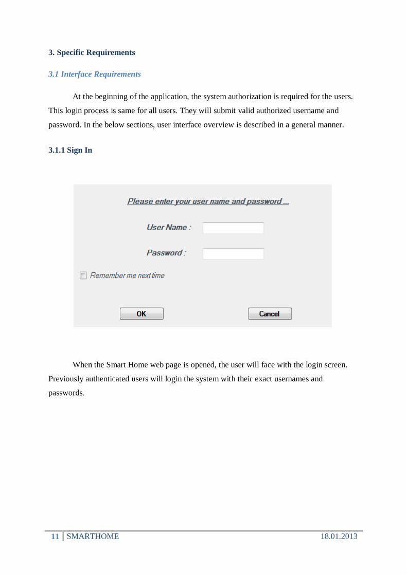
3.1.1 Sign In
When the Smart Home web page is opened, the user will face with the login screen.
Previously authenticated users will login the system with their exact usernames and
passwords.

12 SMARTHOME 18.01.2013
3.1.2 Select Category
After the authentication process explained above, the user is waited for category
selection. If the user clicks on one of the links below the icons, the user will be redirected to a
new page related to the clicked category adjustments. There is also a sign out preference on
the screen, which allows the user to log out from the system.

13 SMARTHOME 18.01.2013
3.1.3 Adjust Configurations
For each appliance, it is required to have a configuration panel. For illustrative
purposes, the above screenshot shows an example configuration panel of a refrigerator. There
are two types of adjustments seen on the interface. One of them is the freezer temperature in
Fahrenheits and the other one is the fridge temperature in Fahrenheits too. The user should be
able to adjust them by clicking on the plus and minus buttons as increasing and decreasing
functionalities relatively.

14 SMARTHOME 18.01.2013
3.1.4 Sign Out
It is also required to have a sign out window to provide continuity. If the user clicks on
the sign out button seen on every page after signing in, s/he will be redirected to the page
whose screenshot is shown on the above picture. There are two choices left after signing out:
OK and Home Page. If the user clicks on the OK button, the window will be closed. If the
user clicks on Home Page, the user should be redirected to login page previously described.

15 SMARTHOME 18.01.2013
3.2 Non-functional Requirements
3.2.1 Performance requirements
The resulting home automation system should perform on home appliances and various
sensors having the ability of compatibility more than the ones in the market. Additionally a
more general communication protocol and wireless controller hardware should be used to
make the system perform on much more devices. The system should access data in reasonable
time. The data transfers between the devices such as actuators and sensors with master
controller should not exceed the time limit of 3 seconds and lie under the throughput of 250
Kbps. Additionally, the system should service with the 7 days / 24 hours availability. The
system should work smoothly with other existing connection networks at home.
3.2.2 Design constraints
The reporting of the project should be in IEEE standards and its diagrams should be
drawn in UML standards. The interface between the system components should be well
described to make the user control easier. As an environment constraint, master controller
software should be developed on Linux system. Moreover, there is another constraint on
wireless communication protocol. In this system, ZigBee wireless protocol should be used to
make the devices communicate. The transmitted information between the devices should be
carried in encrypted form, as a security constraint.
3.2.3 Security constraints
Security is another design constraint. The system should encrypt/decrypt the data
transmitted between the Xbee-Pro devices.
3.3 Functional Requirements
In order to make the user manipulate the system, we need 5 general functions working on
a home appliance included in the home automation system with the help of sensors and
required connections. Each function is explained with the use cases below.

16 SMARTHOME 18.01.2013
3.3.1 Choose a Device
3.3.1.1 Background Information
There will be different kinds of home appliances included in the home automation
system.
3.3.1.2 Action/Response Sequences
3.3.1.2.1 Diagram
3.3.1.2.2 Description
Actor User
Purpose The aim of this function to enable the user to choose a device from the
context.
Precondition The system should be on mode and the user should start the application.
Trigger The user should choose a device from the menu by clicking on it.
3.3.1.2.3 Normal Flow of Events
1. The user selects the device and sees its current condition.
2. The user can manipulate the appliance with given commands.
3.3.1.2.4 Alternative Flow of Events
1. The user tries to use other functions before choosing a device.
2. The system gives a warning message.
user
Choose a Device
17 SMARTHOME 18.01.2013
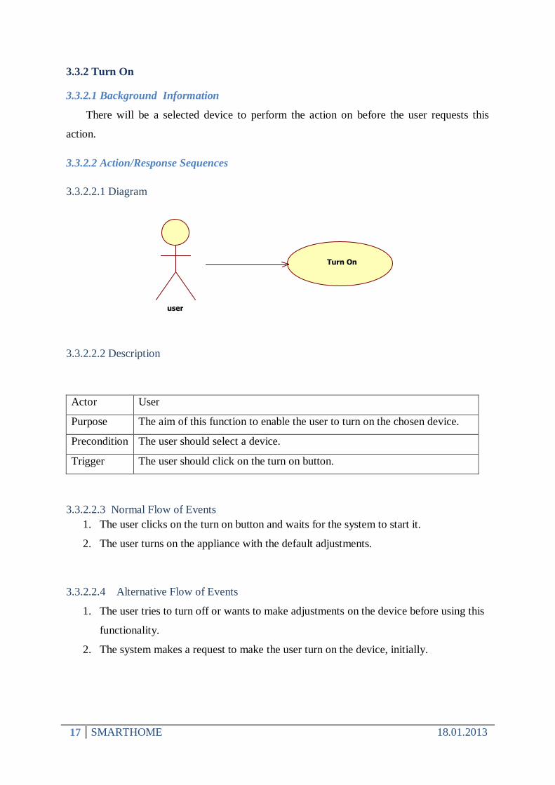
3.3.2 Turn On
3.3.2.1 Background Information
There will be a selected device to perform the action on before the user requests this
action.
3.3.2.2 Action/Response Sequences
3.3.2.2.1 Diagram
3.3.2.2.2 Description
Actor User
Purpose The aim of this function to enable the user to turn on the chosen device.
Precondition The user should select a device.
Trigger The user should click on the turn on button.
3.3.2.2.3 Normal Flow of Events
1. The user clicks on the turn on button and waits for the system to start it.
2. The user turns on the appliance with the default adjustments.
3.3.2.2.4 Alternative Flow of Events
1. The user tries to turn off or wants to make adjustments on the device before using this
functionality.
2. The system makes a request to make the user turn on the device, initially.
user
Turn On

18 SMARTHOME 18.01.2013
3.3.3 Get Sensor Info
3.3.3.1 Background Information
There will be sensors placed into the home appliances to perform this action.
3.3.3.2 Action/Response Sequences
3.3.2.3.1 Diagram
3.3.2.3.2 Description
Actor User
Purpose The aim of this function to enable the user to learn info about the device
from the sensors.
Precondition The device should have atruely working sensor connected to the system.
Trigger The user should click on the’get the current condition’ button.
3.3.2.3.3 Normal Flow of Events
1. After clicking on the above mentioned button, the system starts to communicate with
the device.
2. A window appears on the screen to make the user learn the condition of the device.
3.3.2.3.4 Alternative Flow of Events
1. The sensor data may not be transferred properly.
2. A warning should appear on the screen indicating that the info could not be reached by
the system and request the user to try again.
user
Get Sensor Info

19 SMARTHOME 18.01.2013
3.3.4 Adjust
3.3.4.1 Background Information
Well described adjustment panels on the interface will be provided for each device
included in the system.
3.3.4.2 Action/Response Sequences
3.2.2.4.1 Diagram
3.3.2.4.2 Description
Actor User
Purpose The aim of this function is to enable the user to make the adjustments
according to the device capabilities.
Precondition The system should switch on the true adjustment menu according to the
chosen device and make sure that sensor info is not obsolete by updating
the sensor info.
Trigger The user should enter the adjustment type and content into the adjustment
panel.
3.3.2.4.3 Normal Flow of Events
1. This functionality is device dependent, so generally it can be stated that the user
should click on the adjust button.
2. The device dependent adjustment panel appears on the screen.
3.3.2.4.4 Alternative Flow of Events
1. The user can enter ambiguous adjustments into the panel.
2. The system should give a warning, and continues with the previous adjustments.
user
Adjust

20 SMARTHOME 18.01.2013
3.3.5 Update Sensor Info
3.3.4.1 Background Information
There will be sensors placed into the home appliances to perform this action.
3.3.4.2 Action/Response Sequences
3.3.2.4.1 Diagram
3.3.2.4.2 Description
Actor User
Purpose The aim of this function is to enable the user to update the sensor info
anytime s/he wants.
Precondition The device should have a truely working sensor connected to the system.
Trigger The user should click on the update button.
3.3.2.4.3 Normal Flow of Events
1. The user clicks on the update button.
2. The system updates the sensor info beside the periodic updating times of the system.
3.3.2.4.4 Alternative Flow of Events
1. This command can conflict with the periodic update times.
2. The system continues with the periodic updating without making extra function call.
user
Update Sensor Info

21 SMARTHOME 18.01.2013
3.3.6 Turn Off
3.3.4.1 Background Information
There will be a selected and powered on device to perform the action on before the user
requests this action.
3.3.4.2 Action/Response Sequences
3.3.2.4.1 Diagram
3.3.2.4.2 Description
Actor User
Purpose The aim of this function is to stop the working of the chosen home
appliance.
Precondition The device should be turned on.
Trigger The user should click on the turn off button.
3.3.2.4.3 Normal Flow of Events
1. The user clicks on the turn off button after selecting the device.
2. The system powers the device down and inform the user.
3.3.2.4.4 Alternative Flow of Events
1. The user can try to turn off a device without turning on it before.
2. The system creates a warning message to display on the screen.
user
Turn Off

22 SMARTHOME 18.01.2013
4. Data Model and Description
4.1. Data Objects
4.1.1. Statistical Collection
A relational database collection based on “Device” entity and “Sensor Data” associated
with one another, attributed with a “timestamp” as a unique identifier. Logically, located on
remote server accessed by user, through internet.
4.1.2. Device
Abstract entity of a home appliance.
Statistical_Collection
+timestamp
Device
-device_id-status-type
+set_device_id(int aID)+set_status(bool aStatus)+get_device_id()+get_status()
Washing_Machine
-Program_info-Stage_info-Water_temp-Time_remained+Power_Cons
+Waching_Machine(...)+Get_program_info()+Get_water_temp()+Set_program_info(String aInfo)+Get_time_remained()+Get_power_cons()+Get_stage_info()
Refrigerator
-Temp_setted-Temp_Cur-Power_Cons
+Refrigerator(...)+Get_temp_setted()+Get_power_cons()+Get_temp_cur()+Set_temp_setted(int degree)
23 SMARTHOME 18.01.2013
status: A flag variable containing current status of the appliance. May indicate a malfunction
or problem in device, or proper workstate.
device_id: A unique id which is used when identification of the home appliance.
type: Type of home appliance; may be a lighting, thermostat, refrigerator etc.
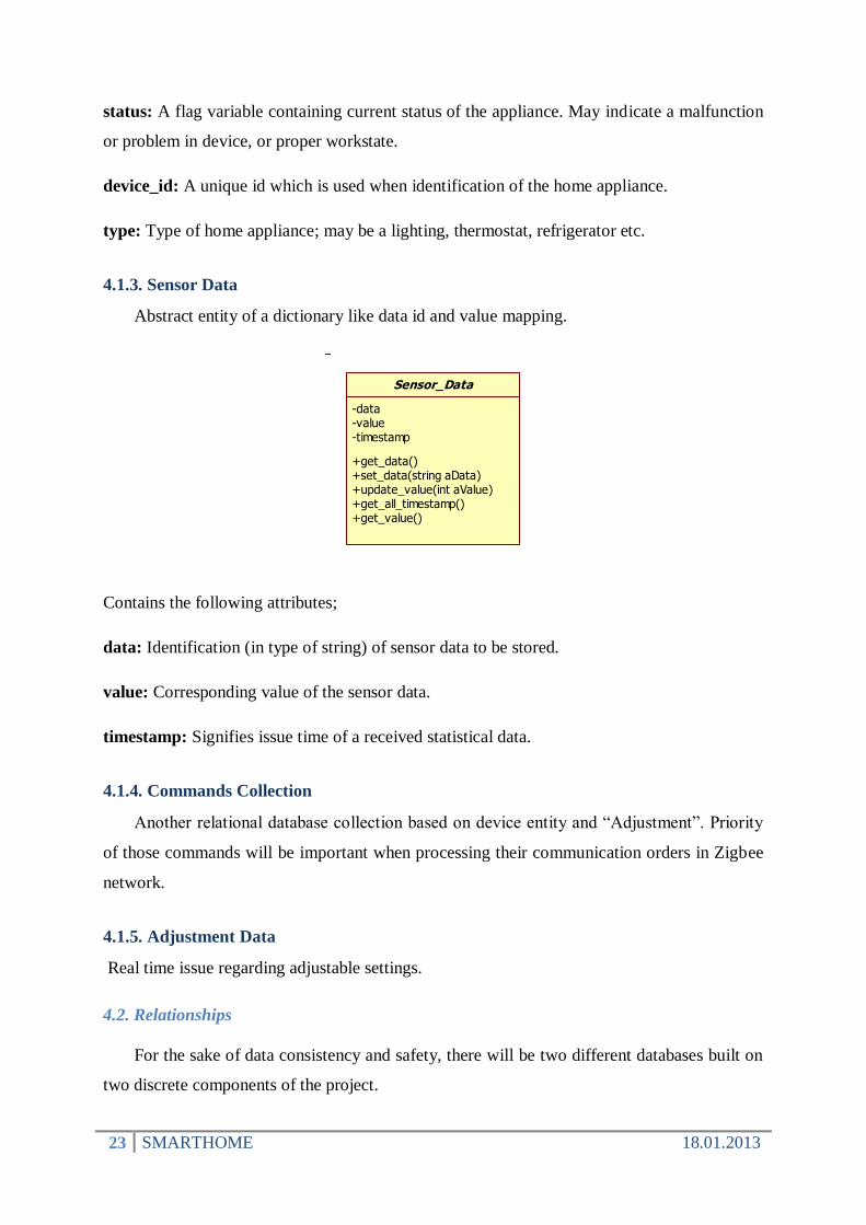
4.1.3. Sensor Data
Abstract entity of a dictionary like data id and value mapping.
Contains the following attributes;
data: Identification (in type of string) of sensor data to be stored.
value: Corresponding value of the sensor data.
timestamp: Signifies issue time of a received statistical data.
4.1.4. Commands Collection
Another relational database collection based on device entity and “Adjustment”. Priority
of those commands will be important when processing their communication orders in Zigbee
network.
4.1.5. Adjustment Data
Real time issue regarding adjustable settings.
4.2. Relationships
For the sake of data consistency and safety, there will be two different databases built on
two discrete components of the project.
Sensor_Data
-data-value-timestamp
+get_data()+set_data(string aData)+update_value(int aValue)+get_all_timestamp()+get_value()

24 SMARTHOME 18.01.2013
Figure: ER Diagram
First one of these databases will be working on server side (“statistic” relation above),
which will be providing statistical data collection about home appliances and will serve as
user interface (client) for remote control of home appliances. This database will hold time
stamped data received from Coordinator Box at home and display this data to user through a
web interface accessible through internet. Commands and adjustments of home appliances in
remote connection will be done through this interface described previously.
Second database will be working on Coordinator Box (“command” relation above), holding a
collection of adjustments, commands and control orders addressing home appliances. In case
of internet connection loss and/or malfunction on Ethernet connection, coordinator device will
continue remaining command items previously received from Server, provided by user
interface.
Device
device_id type status data value
Sensor Data
Adjustment Data
data value
statistic
timestamp
command
priority

25 SMARTHOME 18.01.2013
5. Behavioral Model and Description
5.1. Description for Software Behavior
When user opens the Web based GUI from a browser window, he/she sees a main page
with a list of devices connected to the coordinator box, with few limited details about their
current status. From this list, user can select the device he/she wants to control or view and
reach a detailed page for that specific device. Every home appliance has different features
which can be controlled and monitored through this system, and all of these applicable
information will be provided in the subpage of the selected device.
After a device is selected, user can see all features of that device that can be adjusted
through web interface. After editing specific features user can use “Adjust” button to send
report about these changed features to home appliances. After a reasonable time for data
sending/receiving protocols (around 3 seconds in a fast network), the device to be controlled
will respond to these changes and sensor information will be updated. User can also click on
Update Sensor Info button to order these changes manually. Other than issuing feature
changes for appliances, user can also use Turn Off and Turn On buttons in this page to control
the device itself and start-stop its progress in real time.

26 SMARTHOME 18.01.2013
5.2 State Transition Diagrams
Figure 2: State Transition Diagram of the system
End
Inform the user
Sensor Info
Updated
Condition of
the device
Adjustment
Panel
Adjust
Update
Sensor
Info
Get
Sensor
Info
Initial
Main Page
Chosen
device
Choose a device
Page of
the device
Turn off
Turn on
Turn off

27 SMARTHOME 18.01.2013
5.3. Description of Controller
As controller we are using PIC powered development board in order to control the
appliances. On this control board you can adjust the appliances according to your needs.
There are buttons in order to start or stop the appliances and an adjust button in order to adjust
the temperature or the program information of the appliances. These adjustments can also be
done using the application via Internet. After you adjust the configuration you want, it also
sends the information to the system In order to protect the synchronization between the
system and the controller.
6. Planning
6.1 Team Structure
Our contact from the sponsor company Arcelik is İhsan Mert Özçelik with whom we
discuss about our project process nearly once a week. Since project has interdependent
hardware parts that can be combined after certain development phases, we decided to split our
team into four. Team structure is listed below with their corresponding responsibilities.
Abdullah Hasan Taher Bayrakdar - Web GUI Development and Server Base in Linux
Anıl Ulutürk - Zigbee Wireless Networking and Data Modeling
Zeynep Mavuş – Embedded Development with connection to Zigbee end devices
Şerafettin Öztürk - Linux development with connection to Zigbee coordinator devices
Even though project has been split into two parts, each member will have information
about each part of the project at the end of development cycles defined in next subsections.

28 SMARTHOME 18.01.2013
6.2 Basic Schedule
The Gantt chart that shows the basic time schedule of the project is as follows with the
tasks and dates included.
Figure3: Gantt chart

29 SMARTHOME 18.01.2013
6.3 Process Model
Main model we will use in this project is Waterfall Lifecycle. First we have done
research about market and currently developed home automation systems. Discussing their
pros and cons, we decided on extra features we may add to come up with an interesting
design. According to Waterfall model, Requirements Analysis and Specification was the next
step. After the completion of the first version of this SRS document we came to end of second
step and got started to design process. As many of the project’s design choices were not clear,
we decided to leave behavioral and data model definitions to be next step in our process
model. After design phase, we will continue with implementation. When implementation of
two subparts of the project becomes near completion, we will deal with combining,
maintenance and testing of full set of requirements in this document.
Figure4: Waterfall Model

30 SMARTHOME 18.01.2013
7. Conclusion
This SRS document gives information about the SMARTHOME project which is an
easy to deploy home automation system enhanced with machine learning features. At the
beginning of this document, problem is defined and similar products in market are compared
with our product. Afterwards, functionality of the application, requirements of the application,
performance, attributes and design constraints are clarified in following subsections. In the
overall description part, all of the functions that this application will perform are explained in
detail for developers and future contributors. In the previous part, approximate plan of the
project’s progress is described tentatively. This document will hopefully constitute the base of
design, development, and testing phases of the SMARTHOME project.