
Mid-level Smoke Control for 2D Animationgraphics.cs.cmu.edu/nsp/papers/BarnatGI2011.pdf ·...
8
Mid-level Smoke Control for 2D Animation Alfred Barnat Carnegie Mellon University Zeyang Li Stanford University * James McCann Adobe Systems, Inc. * Nancy S. Pollard Carnegie Mellon University Figure 1: Our mid-level fluid control system allows artists to specify local smoke behavior by providing density motifs (left). The resulting fluid can be integrated with 2D animations (center left). In this case, we have recolored the smoke to match the wand colors. Other effects our system can generate (center right) include global textures such as clouds reminiscent of those found in Katsushika Hokusai’s prints (right). ABSTRACT In this paper we introduce the notion that artists should be able to control fluid simulations by providing examples of expected lo- cal fluid behavior (for instance, an artist might specify that magical smoke often forms star shapes). As our idea fits between high-level, global pose control and low-level parameter adjustment, we deem it mid-level control. We make our notion concrete by demonstrat- ing two mid-level controllers providing stylized smoke effects for two-dimensional animations. With these two controllers, we allow the artist to specify both density patterns, or particle motifs, which should emerge frequently within the fluid and global texture motifs to which the fluid should conform. Each controller is responsible for constructing a stylized version of the current fluid state, which we feed-back into a global pose control method. This feedback mechanism allows the smoke to retain fluid-like behavior, while also attaining a stylized appearance suitable to integration with 2D animations. We integrate these mid-level controls with an interac- tive animation system, in which the user can control and keyframe all animation parameters using an interactive timeline view. Index Terms: I.3.4 [Computer Graphics]: Graphics Utilities—Graphics packages; I.3.7 [Computer Graphics]: Three- Dimensional Graphics and Realism—Animation 1 I NTRODUCTION Current approaches for controlling fluid simulation fall into two bins: low-level and high-level. Low-level controls, e.g. Foster and Metaxas [6], give artists tools to tweak basic simulation parame- ters or create local effects. These methods are useful when an artist is trying to model a specific fluid (honey instead of water, for in- stance), or get a general behavior (explosion, splash). In contrast, high-level controls, e.g. Treuille et al. [18], modify fluid behavior to attain target poses. These techniques give artists and directors explicit global control over fluid pose, perhaps at the expense of realism. * Work performed while at Carnegie Mellon University. Figure 2: Katsushika Hokusai’s iconic wood-block prints feature fluids which have a striking and consistent local appearance that would be hard to duplicate with current high-level or low-level fluid control methods. But what of an artist who has a specific notion of local fluid be- havior, but simply wishes for the global fluid pose to evolve natu- rally? For instance, the water and clouds appearing in classic wood- block prints by Hokusai (Figure 2) have a striking appearance that goes beyond simple stylization and would be hard to duplicate in a classic high- or low-level control framework. For this, a new type of fluid control is needed: mid-level control. We consider a mid-level control approach to be one that main- tains the ambiguity of an artist’s intent – controlling specific local fluid behaviors while allowing the global fluid pose to evolve nat- urally due to physics. Thus, any mid-level control approach must make two choices: first, what sort of local properties artists should be able to specify; and, second, how these properties will be main- tained. There are of course many valid answers to these questions, but – in this paper – we will describe a specific mid-level smoke con- trol framework designed for integration with two-dimensional ani- mations (Figure 1). We choose to let artists specify fluid behavior by providing local density patterns, or particle motifs, that should appear frequently over the course of the simulation (for instance, skulls in a dangerous miasma, or spirals and stars in a powerful magic aura), as well as a globally applied but locally enforced tex- ture motif, which controls the overall appearance of the fluid (as in the appearance of Hokusai’s clouds). We cause these density pat- terns to emerge by using a continuously-updated stylized version of the present density field as a target for a global smoke-control method (Figure 3). This basic premise – using a stylized version of the current fluid state as the target of a global control method – both works well in our specific system and seems like a powerful blueprint for implementing future mid-level controllers. We demonstrate the applicability of our approach by integrating
Transcript of Mid-level Smoke Control for 2D Animationgraphics.cs.cmu.edu/nsp/papers/BarnatGI2011.pdf ·...

Mid-level Smoke Control for 2D AnimationAlfred Barnat
Carnegie Mellon UniversityZeyang Li
Stanford University∗James McCannAdobe Systems, Inc.∗
Nancy S. PollardCarnegie Mellon University
Figure 1: Our mid-level fluid control system allows artists to specify local smoke behavior by providing density motifs (left). The resulting fluidcan be integrated with 2D animations (center left). In this case, we have recolored the smoke to match the wand colors. Other effects our systemcan generate (center right) include global textures such as clouds reminiscent of those found in Katsushika Hokusai’s prints (right).
ABSTRACT
In this paper we introduce the notion that artists should be ableto control fluid simulations by providing examples of expected lo-cal fluid behavior (for instance, an artist might specify that magicalsmoke often forms star shapes). As our idea fits between high-level,global pose control and low-level parameter adjustment, we deemit mid-level control. We make our notion concrete by demonstrat-ing two mid-level controllers providing stylized smoke effects fortwo-dimensional animations. With these two controllers, we allowthe artist to specify both density patterns, or particle motifs, whichshould emerge frequently within the fluid and global texture motifsto which the fluid should conform. Each controller is responsiblefor constructing a stylized version of the current fluid state, whichwe feed-back into a global pose control method. This feedbackmechanism allows the smoke to retain fluid-like behavior, whilealso attaining a stylized appearance suitable to integration with 2Danimations. We integrate these mid-level controls with an interac-tive animation system, in which the user can control and keyframeall animation parameters using an interactive timeline view.
Index Terms: I.3.4 [Computer Graphics]: GraphicsUtilities—Graphics packages; I.3.7 [Computer Graphics]: Three-Dimensional Graphics and Realism—Animation
1 INTRODUCTION
Current approaches for controlling fluid simulation fall into twobins: low-level and high-level. Low-level controls, e.g. Foster andMetaxas [6], give artists tools to tweak basic simulation parame-ters or create local effects. These methods are useful when an artistis trying to model a specific fluid (honey instead of water, for in-stance), or get a general behavior (explosion, splash). In contrast,high-level controls, e.g. Treuille et al. [18], modify fluid behaviorto attain target poses. These techniques give artists and directorsexplicit global control over fluid pose, perhaps at the expense ofrealism.
∗Work performed while at Carnegie Mellon University.
Figure 2: Katsushika Hokusai’s iconic wood-block prints feature fluidswhich have a striking and consistent local appearance that wouldbe hard to duplicate with current high-level or low-level fluid controlmethods.
But what of an artist who has a specific notion of local fluid be-havior, but simply wishes for the global fluid pose to evolve natu-rally? For instance, the water and clouds appearing in classic wood-block prints by Hokusai (Figure 2) have a striking appearance thatgoes beyond simple stylization and would be hard to duplicate in aclassic high- or low-level control framework. For this, a new typeof fluid control is needed: mid-level control.
We consider a mid-level control approach to be one that main-tains the ambiguity of an artist’s intent – controlling specific localfluid behaviors while allowing the global fluid pose to evolve nat-urally due to physics. Thus, any mid-level control approach mustmake two choices: first, what sort of local properties artists shouldbe able to specify; and, second, how these properties will be main-tained.
There are of course many valid answers to these questions, but– in this paper – we will describe a specific mid-level smoke con-trol framework designed for integration with two-dimensional ani-mations (Figure 1). We choose to let artists specify fluid behaviorby providing local density patterns, or particle motifs, that shouldappear frequently over the course of the simulation (for instance,skulls in a dangerous miasma, or spirals and stars in a powerfulmagic aura), as well as a globally applied but locally enforced tex-ture motif, which controls the overall appearance of the fluid (as inthe appearance of Hokusai’s clouds). We cause these density pat-terns to emerge by using a continuously-updated stylized versionof the present density field as a target for a global smoke-controlmethod (Figure 3). This basic premise – using a stylized versionof the current fluid state as the target of a global control method –both works well in our specific system and seems like a powerfulblueprint for implementing future mid-level controllers.
We demonstrate the applicability of our approach by integrating
it with an interactive animation system. The animation is controlledby setting keyframe values for control parameters, and the systemautomatically renders the animation as the user is working. Wedemonstrate the effectiveness of this system by adding controlledsmoke to several 2D animations.
2 BACKGROUND
Fluid animation in graphics has a rich history. Below, we highlighta few works which are the most relevant to our mid-level controlscheme. For general information on simulated fluids in graphics,we refer the reader to a recent survey paper [17].
Our smoke simulations use the global control method of Fat-tal and Lischinski [5] as a primitive. Where Fattal and Lischinskidemonstrated this approach with user-specified keyframes, we au-tomatically generate and continuously update the fluid target.
Several alternative global control methods exist, though none areas well suited to our needs as the above. One approach, given byTreuille et al. [18] and later refined using the adjoint method [10],works by finding optimal driving forces that will allow smoke (orliquid) to match a sequence of user-specified keyframes. As thesemethods require knowledge of targets several frames in the future,they are not well suited to our needs. A different approach, pre-sented by Lin and Yizhou [15], defines an implicit surface for boththe target shape and current density fields, and adds velocities inorder to push the density surface towards the target. This method isnot especially well suited for use with our target density fields, sincethey do not necessarily define discrete objects and instead define afield of density values to be matched.
The control method of Schpok et al. allows users to manipu-late flows using a vocabulary of mid-level features extracted fromthe simulation [13]. Similar control may be achieved by using asimplified basis for the simulated velocity field, as in the methodof Angelidis et al. [1]. Here, the velocity field is represented as aset of vortex filaments, allowing an animator to more easily under-stand the effect of any modifications. However, in both of thesecases, users are limited to local structures they do not select.
Another consideration in artistic fluid control is the ability topreserve overall behavior between low- and high-resolution sim-ulations. Nielsen and Christensen offer a solution to this by us-ing a low-resolution simulation to guide the global behavior ofa corresponding high-resolution simulation, while allowing high-frequency details to emerge [12].
Stylized fluid rendering approaches seek to present the output ofa fluid animation in a given style. One such approach is the useof billboard particles for cartoon smoke rendering [9, 14]. Anotherapproach is to use a texture synthesis technique controlled by thevelocity field produced by the simulation [2, 7, 8, 11]. Perhaps themost similar of these techniques to our own is that of Ma et al. [8],which uses texture synthesis to sequentially apply a velocity ex-emplar, or motif, to each frame of an animation. This technique issimilar in that the textured velocity field for each frame is seeded byadvecting the textured field from the previous frame. However, tex-turing the velocity field instead of the density field limits the artist’sability to specify desired density configurations, and more impor-tantly, the texturing is unable to affect any underlying simulation.In all of these approaches, there is no feedback loop – in our sys-tem, the stylization is more than just cosmetic, it actually changeslong-term fluid behavior.
3 CONTRIBUTIONS
We introduce a technique for artist-directed fluid stylization withfeedback into the underlying simulation. We use the current fluidstate in order to determine how and where motifs appear in the fluid,with the goal being to move the fluid incrementally to match theartist’s desired look (Figure 3). The changes caused in the fluid bythese motifs in turn feed back into the selection mechanism used
Figure 3: We achieve mid-level control by adding stylization feedback(solid border) to an existing smoke control method [5] (dotted border).
to place motifs in future frames. We have developed two mid-levelfluid control techniques making use of this feedback mechanism.
The first of these techniques places motif particles, representingshapes the artist wishes to appear in the fluid. Both the initial place-ment of these particles and their motion is determined by the fluidstate. The presence of these particles then affect the local behaviorof the fluid, feeding back into the underlying simulation.
Our second technique works across the entire fluid, attemptingmove the fluid to match an artist-specified texture motif. This isdone by using a texture transfer technique to construct a stylizedversion of the fluid state. This stylized fluid is then used to guidethe underlying simulation, thus completing the feedback loop.
4 METHOD
We build our system on the global smoke control method of Fat-tal and Lischinski [5]. Instead of using predetermined keyframes,we feed-back a stylized version of the density field as the smoketarget (Figure 3). The stylized density field can be generated usingeither a collection of motif particles or a motif texture. Motif par-ticles cause localized regions of the fluid which already correspondroughly to one of a set of user-defined patterns to match the pat-tern more closely. Motif textures work globally, causing the fluid toconform to the patterns present in a user-defined sample image.
4.1 Smoke ControlSince our system uses target-driven smoke [5] as a primitive, webriefly summarize its operation. It is the goal of target-driven smoketo drive the current density field ρ toward some target density fieldρ∗. To do so, driving forces F(ρ,ρ∗) and damping forces vdu areintroduced into the equations of fluid motion:
ut =−u ·∇u−∇p+ v f F(ρ,ρ∗)− vdu+ f (1)
∇ ·u = 0 (2)
Here, u is fluid velocity, p is pressure, f is external force, and v fand vd are constants giving strength of control and damping.
The driving force F(ρ,ρ∗) moves fluid along the normalized gra-dient of the blurred target density ρ∗:
F(ρ,ρ∗)≡ ρ∇ρ∗
ρ∗(3)
(The ρ factor serves to reduce forces where no density exists.)Additionally, a gathering term, G(ρ,ρ∗) is introduced to the
density advection equation to combat numerical dissipation:
ρt =−u ·∇ρ + vgG(ρ,ρ∗) (4)
Where G(ρ,ρ∗) is defined to reduce error in matching the targetdensity (that is, ρ−ρ∗), wherever there exists density in the vicinityof the target (thus the ρρ∗ factor):
G(ρ,ρ∗)≡ ∇ · [ρρ∗∇(ρ−ρ
∗)] (5)

4.2 Motif Particles
Figure 4: Left, a frame from an animation using our motif particlemethod. Middle, motif particle locations in boxes. Right, the stylizeddensity field (used as the control target for the next frame).
Our motif particle method produces a target density field thatwill cause artist-specified patterns to emerge naturally in the fluid.The artist specifies these patterns, or motifs, as a set of small imagesof desired fluid density. It is the job of our motif particle methodto select locations and orientations where these motifs will emerge.To do so, our method uses motif particles to match and track localsmoke features that resemble these motifs (Figure 4). These motifparticles are blended with the current density field to produce thecontrol target. This has the effect of causing motifs to form in thesmoke and persist until destroyed by turbulence.
4.2.1 Motif Matching
It is important for motif particles to appear only in regions alreadysomewhat similar in appearance to their motifs. We find such posi-tions in two steps. First, we find possible good matches by using asimplified rotation-invariant matching scheme inspired by ring pro-jection [4]: we compute a descriptor at each point of the fluid gridby computing the average density at four radii (Figure 6). Thisdescriptor is compared to a similar descriptor computed over eachmotif, and locations which are above a distance threshold are dis-carded. Then, for those locations that pass the rotation-invariantmatching, we check 32 rotations using an opacity-weighted euclid-ian distance operator over all pixels in the motif to see if there aregood matches to the fluid among them. If any match we find is goodenough (i.e. under a user-defined threshold), we introduce a motifparticle to track the location and rotation of the match. In orderto avoid creating overlapping particles, we do not consider regionsalready covered by motif particles during this matching process.
In practice the initial matching threshold must be carefully tunedaccording to the motif complexity. If the motif is a simple shapewhich is likely to appear occasionally without help, then the thresh-old can be low. For more complex shapes, a higher threshold isneeded. It is also possible to mask out parts of a motif image us-ing the alpha channel, so that they do not contribute to the motifmatching. For instance, if a motif is uniformly colored with theshape created only by the alpha channel, it will match any area of
Figure 6: In our first motif-matching phase we use a rotation-invariantdescriptor consisting of the average of 32 samples at each of fourradii, as pictured. Sample locations are represented by small circlesand the region being matched (e.g. a particle motif) is representedby the square background.
the fluid with the correct color regardless of how well the fluid con-forms to its shape.
4.2.2 Motif Particle BlendingWe initialize the control target, ρ∗, with the current density field,then blend the motif particles, M, one at a time. The blendingfunction is user-specified combination of over blending (whenβ = 1,γ = 0) and add blending (when β = 0,γ = 1). The resultis clamped to the valid range of density values, [0,1]:
ρ∗(x)← (1−βMα (x))ρ∗(x)+(γ +β )Mα (x)Mρ (x) (6)
Here, the motif represented by motif particle M has density Mρ (x)and opacity Mα (x) at location x when translated and rotated to M’sposition.
It is important to note that particle motifs are never blended di-rectly into the density field, either during simulation or before out-putting the density field. Instead, they are blended into a copy ofthe density field which is used as a target for target-driven smoke inthe current frame and then discarded.
4.2.3 Motif Particle AdvectionWhen the density field is advected, we also update our motif parti-cles based on the fluid motion. To do so, we solve for the linear andangular velocities that best match the motion of the smoke, thenupdate the motif particle position based on these velocities. Thatis, given a motif particle centered at c whose opacity at point x isgiven by Mα (x) we compute linear velocity v and angular velocityω which are close, in opacity-weighted squared difference, to thefluid velocity u:
argminω,v
∑x
Mα (x)(ω perp(x− c)+ v−u(x))2 (7)
Here, perp(x) is x rotated by 90 degrees.We found that using the least squares approximation for velocity
given in Equation 7 produced more visually pleasing results thanother approaches we tried, such as simply averaging velocities of asmall number of points, especially in the case of asymmetric par-ticles like the Japanese Hiragana in Figure 4. Our least squaresmethod of evaluation also avoids inaccuracies where particles brushagainst areas of high velocity.
4.2.4 Motif Particle RevalidationOver time, motif particles may no longer match the underlying fluid(if, for instance, turbulence disrupts the motif). We recheck thedistance function for every motif particle at the beginning of eachtime step. We use the same rotation-invariant descriptor that wasused for the initial match, so that the distances are consistent be-tween the initial match and revalidation. If the distance is foundto be above some user-defined threshold, the particle is marked forremoval. This threshold is independent from the initial matchingthreshold, and may be set higher in order to allow the fluid to besomewhat disrupted without causing the particle to be removed.
In addition, we must remove any overlapping particles in orderto prevent clumps of particles from forming in convergent areasof the fluid. To do this, we track particle age, and check for anyparticles which are overlapping older particles. This can be accom-plished during motif blending by tracking, for each pixel, whethera particle has been drawn covering the pixel. If we find that anyparticle overlaps one which has already been drawn, we mark it forremoval. Particles marked for removal are checked last, so that theywill never cause another particle to be marked for removal.
We do not remove particles instantly, as this creates a noticeable“popping” effect. Instead, we fade the influence of the particle lin-early to zero over a user-specified duration d:
Mα (x)←(
1− t− t0d
)Morig
α (x) (8)

Figure 5: The importance of feedback to the particle control method. Simply advecting motif particles (top) produces a far less visually appealingresult than using them as a control target (bottom).
Here, t0 is the time at which the particle began fading.If a particle is found to be matching within tolerance and non-
overlapping at any point before it has fully faded out, it is instantlyreturned to full strength, and no longer marked for removal. Inour experience, this did not cause artifacts because motifs dissipatemuch more easily than they form. However, if a high gatheringvalue were used, it may be desirable to slowly ramp up motif inten-sity rather than allowing motifs to instantly reach full strength.
4.3 Motif Texture
Whereas motif particles work on a local scale, our motif texturemethod produces a global effect across the entire fluid. An artistspecifies a texture motif as a single sample image of a density fieldthat represents the look and behavior they want to capture. It isthe job of our motif texture method to construct a target densityfield which corresponds to the current density field but is stylizedusing the artist-supplied sample (Figure 14). The fluid is drivenincrementally towards a stylized version of itself at each frame, andis able to reproduce complex textures over an extended number offrames.
4.3.1 Texture Transfer
We generate the control target using the PatchMatch algorithm ofBarnes et al. [3], with the current density field as the target and thetexture motif as the source. This constructs an image conformingto the current density field, but with the texture of the motif.
PatchMatch works by incrementally refining a dense correspon-dence of patches between the current density field and the sourcetexture, using a stochastic search. The algorithm attempts to min-imize some distance function across the patches which, in our im-plementation, consist of the 3×3 square area surrounding the desti-nation index and source coordinates, weighted according to a Gaus-sian function with standard deviation 1
2 .The correspondence, consisting of offsets and rotation angles
from the destination into the source image, is initialized using ran-dom but valid values. It is then refined using a two-stage process.First, new, randomly generated offsets and angles are tested at eachpixel. The randomization function used to generate the new offsetsis weighted such that offsets closer to the current offset are morelikely to be tested. Second, offsets along with their correspondingangles are transferred to adjacent pixels, in both forward and re-verse scan-line order. This allows large poorly matching areas to bequickly refined using a small number of good matches.
We use a modified distance function in order to capture large-scale features. Instead of simply computing the weighted distance
Patch Offsets
ixl
Source Texture
oo′
θ
l
Figure 8: In order to prevent drift in the texture offsets, we must ac-count for the offset between the end-location of the advection back-trace and the nearest grid point (Equation 9).
between pixels at the source and destination, we compute this dis-tance across all levels of both a Gaussian pyramid and a Laplacianpyramid (Figure 15). We then sum the distances over all levelsof each, and add these cumulative distances according to a user-specified weighting (Figure 11). This allows us to capture not onlythe absolute color of the target texture motif, but also relative colorchanges. By taking the distance at multiple scales, we capture bothfine-scale texture and large-scale shapes in the target.
In order to construct the density target from the patch correspon-dence, we simply compute the average at each pixel of all patchcolors with a non-zero weight at that pixel. Given our 3× 3 patchsize, this means the color at each pixel of the target is controlledby the patch at that pixel, as well as the patches at all surroundingpixels. As with the particle motifs, we do not hope to force thefluid to conform to this target in one frame, but instead rely on thecumulative effect over several frames.
4.3.2 Texture AdvectionWe do not initialize patch offsets and angles to random values at ev-ery frame. Instead, we advect the correspondence from the previousframe. This advection is similar to density advection with severaladditional requirements. Namely, it does not make sense to inter-polate patch offsets or angles, since interpolating between patcheswhich do not correspond to the same area of the source texture willyield an arbitrary new offset and angle which we cannot expect tocorrespond to a good match. Additionally, patch angles must beupdated based on the fluid motion.
The first requirement is easily satisfied by using nearest-neighborinterpolation at the end of the backtrace step. However, this leads
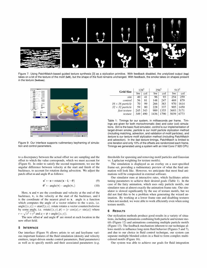
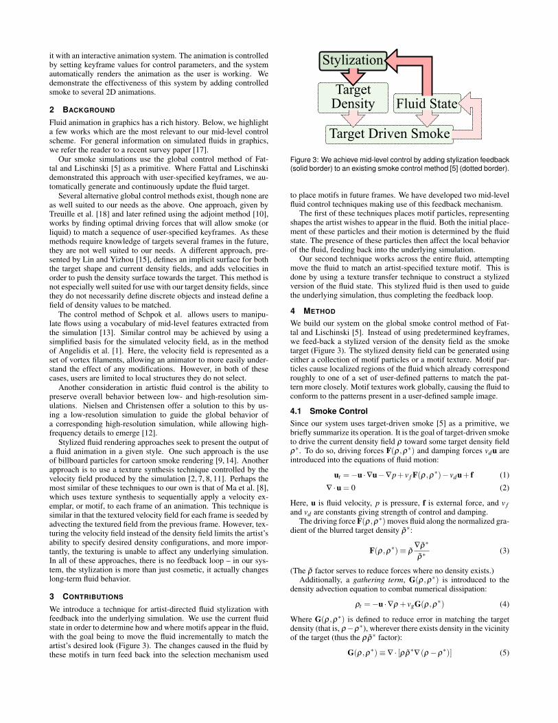
Figure 7: Using PatchMatch-based guided texture synthesis [3] as a stylization primitive. With feedback disabled, the unstylized output (top)takes on a bit of the texture of the motif (left), but the shape of the fluid remains unchanged. With feedback, the smoke takes on shapes presentin the texture (bottom).
Figure 9: Our interface supports rudimentary keyframing of simula-tion and control parameters.
to a discrepancy between the actual offset we are sampling and theoffset to which the value corresponds, which we must account for(Figure 8). In order to satisfy the second requirement, we use theangular difference between velocity at the start and finish of thebacktrace, to account for rotation during advection. We adjust thepatch offset o and angle θ as follows:
o′← o+ rotate(x− i,−θ) (9)
θ′← angle(v)− angle(v◦) (10)
Here, x and v are the coordinate and velocity at the end of thebacktrace, v◦ is the velocity at the start of the backtrace, and iis the coordinate of the nearest pixel to x. angle is a functionwhich computes the angle of a vector relative to the x-axis, i.e.angle((x,y)) = atan2(y,x). rotate rotates a vector counterclockwiseby some angle, i.e. rotate((x,y),φ) = (r · cos(a),r · sin(a)) wherer =
√x2 + y2 and a = φ + angle((x,y)).
The new offset o′ and angle θ ′ are stored at each location in thenew offset field.
5 INTERFACE
Our interface (Figure 9) allows artists to set and keyframe vari-ous important features of the fluid simulation (density and velocityemitters, target-driven smoke control parameters, fluid parameters)as well as to specify motifs and their associated parameters (e.g.
Grid Size 1282 2562 5122
bw col bw col bw colsim 40 41 96 93 254 259
control 56 81 148 247 469 87916×16 particle 70 99 266 383 970 161432×32 particle 59 80 228 337 905 1450
fast texture 245 343 989 1355 3693 5171texture 349 490 1436 1790 5039 6773
Table 1: Timings for our system, in milliseconds per frame. Tim-ings are given for both monochromatic (bw) and color (col) simula-tions. Sim is the basic fluid simulator, control is our implementation oftarget-driven smoke, particle is our motif particle stylization method(including matching, advection, and validation of motif particles), andtexture is our texture motif stylization method (including PatchMatchand advection). In the fast texture timings, PatchMatch is limited toone iteration and only 10% of the offsets are randomized each frame.Timings we generated using a system with an Intel Core i7 920 CPU.
thresholds for spawning and removing motif particles and Gaussianvs. Laplacian weighting for texture motifs).
The simulation is displayed as an overlay on a user-specifiedframe-set, providing a rudimentary preview of what the final ani-mation will look like. However, we anticipate that most final ani-mations will be composited in external software.
Our simulator runs at interactive rates, which facilitates artiststuning parameters to achieve their desired goals (Table 1). In thecase of the fairy animation, which uses only particle motifs, oursimulator runs at almost exactly the animation frame rate. Our sim-ulator is slowed significantly by the use of texture motifs, but wedid not find this to be a problem when generating the wizard an-imation. By working at a lower frame rate and disabling textureswhen not needed, we were able to work efficiently even when usingtexture motifs.
6 RESULTS
Our stylization methods produce good results in a variety of situa-tions, including animations combining both particle and texture mo-tifs (Figure 12) and animations containing multiple particle motifs(Figure 13). The feedback mechanism inherent to our technique al-lows motifs to influence long-term fluid behavior (Figures 5 and 7),and due to our choice in fluid control technique, our system canseparate multiple blended colors in a fluid to form complex multi-colored motifs (Figure 16).
Our system was able to achieve our goals for fluid integration

Figure 11: A comparison of different Gaussian vs. Laplacian weightings. Top, the Laplacian difference is weighted 0.8 while the Gaussian isweighted 0.2. This somewhat emphasizes the edges present in the texture. Middle, an identical underlying simulation without the mist motif.The velocity attenuation step of target-driven smoke remains enabled. Bottom, the Laplacian difference is weighted 0.2 and the Gaussian isweighted 0.8. This places more emphasis on matching absolute color values.
Figure 12: By combining an eerie texture and skull particle, we are able to control both specific motif shapes and overall fluid appearance.
Figure 13: Hiragana characters form from wisps of smoke.
with animations. In the frog animation (Figure 17), we were able toindicate the transition of the pot’s contents from a benign brew to aputrid potion by using varying colors of smoke and applying a skullmotif. We enhance the effect by enabling a texture motif to give thesmoke more substance. In the smoking animation (Figure 10), thecharacter quizzically cocks an eyebrow as she inhales, and her puz-zled attitude is reflected by the question-mark motifs that emergeas she exhales. In the wand animation (Figure 1), we indicate thepower of the fairy’s giant wand through an aura of spirals and stars.
Our simulator is based on the approach outlined by Stam [16],with velocities represented at cell edges instead of centers, addedsteps to compute smoke control forces and perform gathering, anda multigrid linear solver instead of pure Gauss-Seidel relaxation.In addition, we have used the Cilk++ SDK to parallelize most ofour simulator, thus allowing it to take full advantage of modernmulticore machines. A table of timings (Table 1) shows that the
time taken by our particle stylization approach is comparable tothat of the other components of the system, while texture stylizationincreases running time to roughly 10 times that of our target-drivensmoke implementation alone.
When using particle motifs alone, our simulation environmentcan achieve real-time performance for reasonably large simula-tion sizes. (The fairy animation was rendered at a resolution of488× 252.) However, slow texture running times are mitigatedby our system’s automatic and continuous background rendering.Whenever the user makes a change, the animation is re-renderedautomatically from that point, with the progress shown in the time-line. In practical terms, this means that the system remains useableeven when frame rendering is less than real-time.

Figure 10: The woman exhales a cloud of quizzical smoke. Smokeis controlled to form question marks.
7 DISCUSSION
In this paper, we introduced the idea of mid-level fluid control –an approach where artists specify desired fluid behavior at a largerscale than basic simulation parameters, but without resorting toglobal keyframes. To make this notion concrete, we implementeda mid-level smoke controller which causes the fluid to conform toartist-specified density motifs. With the help of our user interface,fluids controlled in this way can be integrated into two-dimensionalanimations to achieve a variety of artistic goals.
Our controller is built around the idea of feeding back styliza-tion information through global pose control, a basic blueprint thatmay prove useful in future mid-level control schemes. We expectthat many techniques used to stylize a fluid animation as a post-processing step could benefit from this feedback mechanism.
Indeed, while we have focused on density, it would be interest-ing to also specify velocity motifs, to control patterns of flow, andsurface motifs, to control boundary shapes when working with liq-uids. In the extreme, one could consider simulating a fluid over afully user-specified basis, perhaps consisting of translated and ro-tated copies of density and velocity motifs. In this case, mid-levelcontrol could be as simple as encouraging sparsity in the repre-sentation – in other words, driving the fluid to states that can berepresented with just a few basis elements.
While our current motif-particle stylization approach is limitedto 2D fluids, we see two routes to generalizing it to 3D: The tech-nically simplest generalization would be to use volumetric motifs.In this case the matching and update steps change trivially, bothin the case of texture and particle motifs (take distances at everyvoxel instead of every pixel); however, the artistic effort requiredto create volumetric motifs is likely to be substantial, and it willbe hard to guarantee that the camera will always view a given motiffrom a pleasing or meaningful angle. Another, more promising, op-tion is to use 2D, screen-space motifs. In this case, particle match-ing and updates could be performed either on the projection of thewhole fluid volume or a slice thereof to screen space. However,this approach requires a new view-dependent fluid control methodwhich may be technically difficult to concoct. Nonetheless, bothapproaches are interesting future work.
Though we do expose intrinsic fluid parameters to the artist foradjustment, it could be useful to automatically select a set of fluidparameters that suit the user-specified motifs. For instance, a veryswirly motif would tend to imply a low-viscosity fluid, while asmooth motif would be natural in a very diffusion-prone setting.
In the future, mid-level fluid control methods have the poten-tial to be a powerful tool for artists who wish to direct the gen-eral look of fluid – velocities, densities, surface shapes, and thetime-evolution thereof – without having to specify the exact globalfluid configuration. Mid-level control is a cooperation between manand machine, integrating the stylistic vision of artists with the com-puter’s grasp of fluid dynamics; producing results that neither partycould create alone.
REFERENCES
[1] A. Angelidis, F. Neyret, K. Singh, and D. Nowrouzezahrai. A control-lable, fast and stable basis for vortex based smoke simulation. In SCA’06: Proceedings of the 2006 ACM SIGGRAPH/Eurographics sym-posium on Computer animation, pages 25–32, Aire-la-Ville, Switzer-land, Switzerland, 2006. Eurographics Association.
[2] A. W. Bargteil, F. Sin, J. E. Michaels, T. G. Goktekin, and J. F.O’Brien. A texture synthesis method for liquid animations. In ACMSIGGRAPH 2006 Sketches, SIGGRAPH ’06, New York, NY, USA,2006. ACM.
[3] C. Barnes, E. Shechtman, A. Finkelstein, and D. B. Goldman. Patch-Match: A randomized correspondence algorithm for structural imageediting. ACM Transactions on Graphics (Proc. SIGGRAPH), 28(3),Aug. 2009.
[4] C.-H. C. Du-Ming Tsai. Rotation-invariant pattern matching usingwavelet decomposition. In Pattern Recognition Letters, pages 191–201. Elsevier Science Inc., January 2002.
[5] R. Fattal and D. Lischinski. Target-driven smoke animation. In SIG-GRAPH ’04: ACM SIGGRAPH 2004 Papers, pages 441–448, NewYork, NY, USA, 2004. ACM.
[6] N. Foster and D. Metaxas. Controlling fluid animation. In CGI ’97:Proceedings of the 1997 Conference on Computer Graphics Interna-tional, page 178, Washington, DC, USA, 1997. IEEE Computer Soci-ety.
[7] V. Kwatra, D. Adalsteinsson, T. Kim, N. Kwatra, M. Carlson, andM. Lin. Texturing fluids. IEEE Trans. Visualization and ComputerGraphics, 13(5):939–952, 2007.
[8] C. Ma, L.-Y. Wei, B. Guo, and K. Zhou. Motion field texture synthesis.ACM Trans. Graph., 28:110:1–110:8, December 2009.
[9] M. McGuire and A. Fein. Real-time cartoon rendering of smoke andclouds. In NPAR, June 2006.
[10] A. McNamara, A. Treuille, Z. Popovic, and J. Stam. Fluid controlusing the adjoint method. In SIGGRAPH ’04: ACM SIGGRAPH 2004Papers, pages 449–456, New York, NY, USA, 2004. ACM.
[11] F. Neyret. Advected textures. In ACM-SIGGRAPH/EG Symposium onComputer Animation (SCA), July 2003.
[12] M. B. Nielsen and B. B. Christensen. Improved variational guiding ofsmoke animations. Comput. Graph. Forum, 29:705–712, May 2010.
[13] J. Schpok, W. Dwyer, and D. S. Ebert. Modeling and animating gaseswith simulation features. In SCA ’05: Proceedings of the 2005 ACMSIGGRAPH/Eurographics symposium on Computer animation, pages97–105, New York, NY, USA, 2005. ACM.
[14] A. Selle, A. Mohr, and S. Chenney. Cartoon rendering of smoke an-imations. In NPAR ’04: Proceedings of the 3rd international sym-posium on Non-photorealistic animation and rendering, pages 57–60,New York, NY, USA, 2004. ACM.
[15] L. Shi and Y. Yu. Controllable smoke animation with guiding objects.ACM Trans. Graph., 24(1):140–164, 2005.
[16] J. Stam. Real-time fluid dynamics for games. In Proceedings fo theGame Developer Conference, march 2003.
[17] J. Tan and X. Yang. Physically-based fluid animation: A survey. Sci-ence in China Series F-Information Sciences, 52(5):723–740, 2009.
[18] A. Treuille, A. McNamara, Z. Popovic, and J. Stam. Keyframe controlof smoke simulations. In SIGGRAPH ’03: ACM SIGGRAPH 2003Papers, pages 716–723, New York, NY, USA, 2003. ACM.

Figure 14: Left, a frame from an animation using our motif texture method. Middle, from left to right: patch x offsets, patch y offsets, and patchrotation angle (red is 0◦, green is 120◦, blue is 240◦). Right, the stylized density field (used as the control target for the next frame).
Gaussian
Laplacian
Figure 15: We use multi-resolution matching on both Gaussian and Laplacian pyramids in order to capture both the absolute color and edgesof the target motif, with a user-specified weighting between the two. A sample Gaussian filter kernel is overlaid on each image, to show whichportions might contribute to a single patch distance computation.
Figure 16: The gathering term of the target-driven smoke control technique [5] allows motifs to separate white smoke into its components.
Figure 17: Top right, a larger view from the last frame below highlights the motifs shown on the top left. Bottom, a wizard puts the final toucheson a toxic potion. Smoke is controlled to form skull motifs and green borders.