
Microwave Signal Generator R&S SMP - Rohde & … Microwave Signal Generator ¸SMP Microwave signals...
14
◆ Instrument family with three models – ¸SMP 02 (10 MHz to 20 GHz) – ¸SMP 03 (10 MHz to 27 GHz) – ¸SMP 04 (10 MHz to 40 GHz) ◆ High output level – ¸SMP02 >+11.5 dBm – ¸SMP03 >+13 dBm – ¸SMP04 >+10 dBm ◆ Optional pulse modulator and pulse generator ◆ Digital RF, AF and level sweep ◆ Storage of 50 complete instrument setups ◆ Optional phase modulator ◆ ASK/FSK modulation, phase offset settings ◆ Extremely low SSB phase noise at 10 GHz (<–105 dBc (1 Hz) at 10 kHz from carrier) ◆ Very short frequency setting time <11 ms + 5 ms/GHz ◆ Extremely high level accuracy <±0.9 dB at 0 dBm in frequency range 10 MHz to 40 GHz Version 05.01 May 2007 Microwave Signal Generator R&S ® SMP Excellent signal characteristics through to 40 GHz Data sheet
Transcript of Microwave Signal Generator R&S SMP - Rohde & … Microwave Signal Generator ¸SMP Microwave signals...

◆ Instrument family with three models– ¸SMP02 (10 MHz to 20 GHz)– ¸SMP03 (10 MHz to 27 GHz)– ¸SMP04 (10 MHz to 40 GHz)
◆ High output level– ¸SMP02 >+11.5 dBm– ¸SMP03 >+13 dBm– ¸SMP04 >+10 dBm
◆ Optional pulse modulator and pulse generator
◆ Digital RF, AF and level sweep◆ Storage of 50 complete instrument
setups◆ Optional phase modulator◆ ASK/FSK modulation, phase offset
settings
◆ Extremely low SSB phase noise at 10 GHz (<–105 dBc (1 Hz) at 10 kHz from carrier)
◆ Very short frequency setting time<11 ms + 5 ms/GHz
◆ Extremely high level accuracy<±0.9 dB at 0 dBm in frequency range 10 MHz to 40 GHz
Version
05.01
May
2007
Microwave Signal Generator R&S®SMPExcellent signal characteristics through to 40 GHz
Dat
a sh
eet
2 Microwave Signal Generator ¸SMP
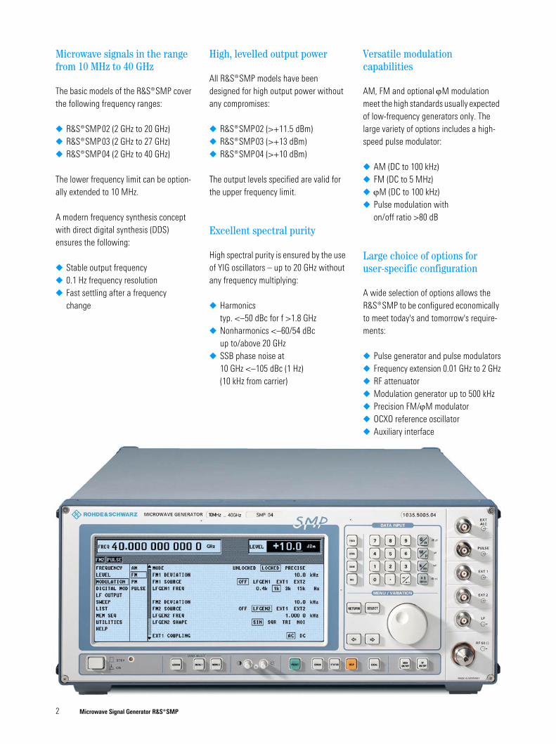
Microwave signals in the range from 10 MHz to 40 GHz
The basic models of the ¸SMP cover the following frequency ranges:
◆ ¸SMP02 (2 GHz to 20 GHz)◆ ¸SMP03 (2 GHz to 27 GHz)◆ ¸SMP04 (2 GHz to 40 GHz)
The lower frequency limit can be option-ally extended to 10 MHz.
A modern frequency synthesis concept with direct digital synthesis (DDS) ensures the following:
◆ Stable output frequency◆ 0.1 Hz frequency resolution ◆ Fast settling after a frequency
change
High, levelled output power
All ¸SMP models have been designed for high output power without any compromises:
◆ ¸SMP02 (>+11.5 dBm)◆ ¸SMP03 (>+13 dBm)◆ ¸SMP04 (>+10 dBm)
The output levels specified are valid for the upper frequency limit.
Excellent spectral purity
High spectral purity is ensured by the use of YIG oscillators – up to 20 GHz without any frequency multiplying:
◆ Harmonics typ. <–50 dBc for f >1.8 GHz
◆ Nonharmonics <–60/54 dBcup to/above 20 GHz
◆ SSB phase noise at10 GHz <–105 dBc (1 Hz) (10 kHz from carrier)
Versatile modulation capabilities
AM, FM and optional ϕM modulation meet the high standards usually expected of low-frequency generators only. The large variety of options includes a high-speed pulse modulator:
◆ AM (DC to 100 kHz)◆ FM (DC to 5 MHz)◆ ϕM (DC to 100 kHz)◆ Pulse modulation with
on/off ratio >80 dB
Large choice of options for user-specific configuration
A wide selection of options allows the ¸SMP to be configured economically to meet today's and tomorrow's require-ments:
◆ Pulse generator and pulse modulators◆ Frequency extension 0.01 GHz to 2 GHz◆ RF attenuator◆ Modulation generator up to 500 kHz◆ Precision FM/ϕM modulator◆ OCXO reference oscillator◆ Auxiliary interface

Microwave Signal Generator ¸SMP 3
Intelligent menu guidance for maximum ease of operation
◆ Large-size LC display◆ Menu-guided operation with all menu
levels being shown at a glance◆ Two menu memories to speed up
operation
User-friendly details
◆ Digital RF, AF and level sweep◆ Storage of 50 complete instrument
setups◆ Combination of any modulation
modes possible◆ Ultra-low RF leakage◆ RF control output
Unambiguous results due to high spectral purity
The outstanding features of the ¸SMP are the extremely low SSB phase noise of <–105 dBc (1 Hz) at 10 GHz (10 kHz from carrier) as well as nonharmonics of <–60/54 dBc up to/above 20 GHz. The high harmonics rejection and the complete absence of subharmonics below 20 GHz cut out time-wasting measurements such as occur with inferior signal generators.
Minimum level error
A highly precise level is required, for example, for measurements and calibra-tion of receivers. A controlled and fre-quency-response-compensated output level is a basic prerequisite for setting accuracy. In conjunction with a precision attenuator (option ¸SMP-B15/-B17), an extremely high level accuracy is ensured throughout the setting range (<±0.9 dB at 0 dBm in the frequency range 10 MHz to 40 GHz).
Stable output frequency
The crystal reference built-in as standard ensures an accurate and low-drift output frequency.
The ¸SMP can also be fitted with an oven-controlled crystal oscillator (option ¸SMP-B1, OCXO) to meet the most exacting requirements.
High output level eliminates the need for add-on units
A large number of microwave measure-ments requires mainly one thing: a high output level, which until now has only been possible with expensive add-on amplifiers.
Owing to their high output levels, the ¸SMP models feature sufficient reserves for compensating the attenua-tion of long cables as well as the losses of power splitters and directional couplers.
Our standard:0.1 Hz frequency resolution
A high frequency resolution is required especially for scientific applications and in industrial research, e.g. for surface measurements of materials using radar equipment.
The ̧ SMP is setting standards with a resolution of 0.1 Hz throughout its fre-quency range, and even above 20 GHz.
–40
–50
–60
–70
–80
–90
–100
–110
–120
–130
–140
dBc
2 4 6 8 2 4 6 8 2 4 6 8 2 4 6 8 2 4 6 810 Hz 100 Hz 1 kHz 10 kHz 100 kHz 1 MHz
30 dBm
28 dBm
26 dBm
24 dBm
22 dBm
20 dBm
18 dBm
16 dBm
14 dBm
12 dBm
10 dBm
8 dBm0.01 2 4 6 8 10 12 14 16 18 20 22 24 26 28 30 32 34 36 38 40 GHz
¸SMP 02 ¸SMP 03
¸SMP 04
FIG 1: SSB phase noise at 10 GHz
FIG 2: Typical maximum level versus frequency

4 Microwave Signal Generator ¸SMP
(2) (2)
90 %
10 %
50 %
(1)
Variety of applications
The ¸SMP is ideal for the following applications:
◆ Substitution of local oscillators◆ Measurements on nonlinear compo-
nents such as frequency multipliers or high-level mixers
◆ Driving of travelling wave tubes (TWTs) and other power stages
◆ Interconnection of several signal generators for intermodulation measurements
◆ Tracking generator for spectrum and network analyzers
High-quality shielding
Sensitivity measurements on low-noise satellite receivers can only be made with absolutely RF-leakage-proof signal sources.
The comprehensive shielding of the ¸SMP ensures extremely low RF leakage.
Frequency and phase modulation
The ̧ SMP is fitted as standard with a broadband FM modulator covering a modulation frequency range up to 5 MHz for deviations up to 10 MHz (20 MHz above 20 GHz).
In addition, a precision FM/ϕM modula-tor (option ¸SM-B5) with a modula-tion frequency range of up to 1 MHz and maximum deviation of up to 1 MHz (2 MHz for f >20 GHz) is available for testing communication receivers and for scientific applications.
FSK modulation
Owing to a special frequency control cir-cuit, the precision FM/ϕM modulator fea-tures an extremely high carrier frequency accuracy and stability in the FM DC mode. Digital frequency shift keying (FSK modulation) is also possible. A deviation of up to 1 MHz (2 MHz above 20 GHz) can be selected.
Wide ϕM modulation range
The wide frequency range of the phase modulation extending from DC to 100 kHz allows testing of phase-sensitive circuits.
¸SMP for use as a VCO
In DC-coupled FM or ϕM mode, the ¸SMP can also be used as a voltage-controlled oscillator (VCO) and integrated into an external frequency control loop. The RF control output fitted on the rear panel is very useful for this application.
The RF control output provides signals in the frequency range 2 GHz to 20 GHz and can, for example, be used for monitoring the output frequency with the aid of a frequency counter (FIG 3).
Pulse modulation
Ideal for radar receivers
All data specified for pulse modulation, which is frequently used in the develop-ment, production and maintenance of radar receivers, is valid throughout the rated frequency range and also at the important intermediate frequencies of 70 MHz and 140 MHz. The on/off ratio is better than 80 dB, the rise/fall time shorter than 10 ns. Pulse widths of less than 20 ns are possible (FIG 4).
Optional pulse generator
In addition to feeding in external modula-tion signals, the pulse generator (option ¸SMP-B14) can also be used to gen-
YIG2 GHz to 10 GHz
YIG10 GHz to 20 GHz
direct
12
¸SMP 03/04
¸SMP-B11
6 GHz
2 GHz to 20 GHz
20 GHz to 40 GHz
10 MHz to 2 GHz
RF out
2 GHz to 20 GHz (RF control output)
EXT1 or EXT2
¸SMP
FM DC non-synchronized (unlocked)
FM/ϕM modulator
Frequency divider/phase comparator/control amplifier
DUT
FIG 4: Pulse modulator, univer-
sally used in microwave applica-
tions such as radar;
(1) shortest pulse duration 20 ns,
(2) typ. 3 ns rise/fall time, more
than 80 dB on/off ratio
FIG 3: ¸SMP as a VCO

Microwave Signal Generator ¸SMP 5
Pulsed transmitter
Pulse generator
Display
LO RF
Sidebandfilter
Circulator
Pulse1
2
Antenna direction pulse
FIG 5: Radar tests (switch position 1 for testing the distance indicated by radar,
switch position 2 for testing the antenna direction indicated by radar)
erate internal single or double pulses with pulse frequencies up to 10 MHz.
The pulse generator can also be triggered externally, pulse width and delay being user-selectable over a wide range.
Simultaneous modulation modes and their application
All modulation modes which the ¸SMP is able to generate can be combined (in the case of the ¸SMP03/04 with some restrictions regarding pulse and amplitude modula-tion). Highly complex signals can thus be generated for modern communication and radar systems.
Doppler effects
The combination of pulse modulation and FM DC simulates Doppler effects and also chirp signals.
Pulse radar with rotating antenna
Combined scan and pulse modulation provides the type of signals occurring in pulse radar applications with rotating antenna.
In the example shown in FIG 5, the exter-nal pulse from the pulse generator or radar display is applied to the external pulse input of the ̧ SMP and used as
a trigger for the internal pulse generator and modulator.
The main advantage of this kind of trigger is that it can be delayed to simulate distance and direction and to check the values on the display.
Fading
Simultaneous frequency and amplitude modulation can be used to study fading effects of FM receivers.
Sweep capabilities
Level sweep
The 20 dB level sweep of the ̧ SMP is an efficient function for determining power characteristics and for compres-sion measurements.
Digital frequency sweep
The digital frequency sweep with steps from 10 ms is a useful facility for measur-ing the frequency response of microwave modules or antennas.
Sweep modes
The digital sweep can be executed auto-matically in repetitive mode or in single-shot mode with selectable sweep time. Manual sweeping (STEP MODE) within the sweep limits is also possible. Trigger
inputs and outputs facilitate synchronous operation in conjunction with other instruments.
Use in EMC measurements
Functions qualifying the ¸SMP for EMC applications include the trigger facility for step-by-step sweeping, marker outputs and, above all, the extension of the frequency range to 10 MHz (option ¸SMP-B11).
The capability of compensating external frequency responses is also an important feature.
Frequency hopping in list mode
One of the very special features of the ¸SMP is the list mode. Unlike the normal sweep mode with increasing or decreasing frequencies, the list mode can be used for programming frequency hop-ping. A list editor makes programming extremely easy. Up to 2003 pairs of frequency and level values can be stored in lists.
Of course, the same types of sweep can be executed in the list mode as in the normal sweep mode.
Frequency response compensation
Power amplifiers, cables, antennas and TEM cells usually exhibit a relatively large frequency response which has to be com-pensated to obtain accurate measure-ment results.
The ¸SMP provides two excellent tools for the correction of external frequency responses:
◆ User-defined correction of external frequency responses
◆ External level control using a power meter

6 Microwave Signal Generator ¸SMP
5
5
5
5
5
5
3
3
FIG 6: Output level with frequency response correction ON (yellow curve) and OFF (orange curve)
Power amplifier DUTHorn antenna
FIG 7: External level control for the Microwave Signal Generator ¸SMP
Power Sensor ¸NRV-Z15
DUT
DC
DC FREQ
RF
EXT ALC
¸SMP
V/GHz
Power splitter
¸NRVS
Trig
ger
GPIB
REF
10 M
Hz
¸SMP
¸FSP + ¸FSP-B10
Blan
king
sig
nal
DUT
Blank
Aux
Aux
Trigger
FIG 8: Scalar network analysis with the Microwave Signal Generator ¸SMP and the
Spectrum Analyzer ¸FSP with option ¸FSP-B10
User-defined correction of external
frequency responses
The user correction function is extremely useful for fast RF sweeps, for example to compensate nonlinearities of an ampli-fier.
The known frequency response can be compensated by entering level correction values for up to 160 frequency points. The correction values for the frequencies between these points are determined by means of automatic interpolation (FIG 6).
In addition, the ¸SMP can automati-cally measure the level correction values at a keystroke with the aid of external power meters such as the ¸NRVS or ¸NRVD.
External level control using a
power meter
A very simple method is the external level control with high level accuracy (FIG 7).
Scalar network analysis
The Microwave Signal Generator ¸SMP used as a tracking generator in conjunction with the Spectrum Analyzer ¸FSP and the option ¸FSP-B10 provides a unique scalar network analysis function. This applica-tion features an extremely wide dynamic range, which allows, for example, filter resonances in the stop band to be displayed at very low levels.
Due to the user-definable frequency offset, measurements on frequency-converting devices can also be performed with this configuration.

Microwave Signal Generator ¸SMP 7
Remote control to SCPI standard
The IEC/IEEE-bus remote control com-mands are in line with the SCPI guide-lines. One of the advantages is that the user can exchange measuring instru-ments in an automatic system without having to modify the control software.
Intelligent operating concept
Easy-to-follow menus
Neither multifunction keys nor obscure special functions burden the user. All functions are clearly arranged in menus. Menus and functions as well as parame-ter settings can be conveniently selected with a spinwheel.
FIG 9: SAVE and RCL for storing and recalling
settings
The FM modulation menu shows the clear-cut representation of selectable parameters and current
instrument status. Each setting can be made quickly and easily by means of the spinwheel and a few
keys.
Menu memories
Frequently used menu settings can be stored in two memories and recalled at a keystroke.
Easy-to-read screen display
All settings associated with a certain function can be seen at a glance on the large-size, high-contrast LC display.
HELP function
Explanatory remarks can be called up for each individual menu. This does away with wasting time in looking up functions in a manual.
FIG 10: General settings and menu selection
with spinwheel, RETURN, SELECT and arrow
keys
Automatic measurement functions for production and test labs
The memory sequence is an extremely useful function. It provides convenient execution of standard test routines or fre-quently required sequences of different types of single measurements.
Up to 50 complete instrument setups can be stored. After programming the sequence of measurements to be exe-cuted, the user can activate the autorun control facility.
This function also allows synchronous operation with other units through trig-gering. Step times can be separately programmed for each step.
FIG 11: Storage of menu settings
FIG 12: Online help

8 Microwave Signal Generator ¸SMP
Expertise in microwaves
Continuity of progress at
Rohde&Schwarz
The name of Rohde&Schwarz is also synonymous with quality in the field of microelectronics.
Large investments have been made in advanced technologies to fully keep up with the ever increasing demands made on the precision and reliability of micro-wave modules. Rohde&Schwarz uses ultra-modern clean rooms and systems for the development and production of thin-film circuits.
Airbridges is an ideal technique for imple-
menting PCB crossovers with excellent high-
frequency characteristics. The photo above
has been taken with a scanning electron
microscope and shows such an airbridge
which is only 0.05 mm long.
Microwave Signal Generator ¸SMP 9
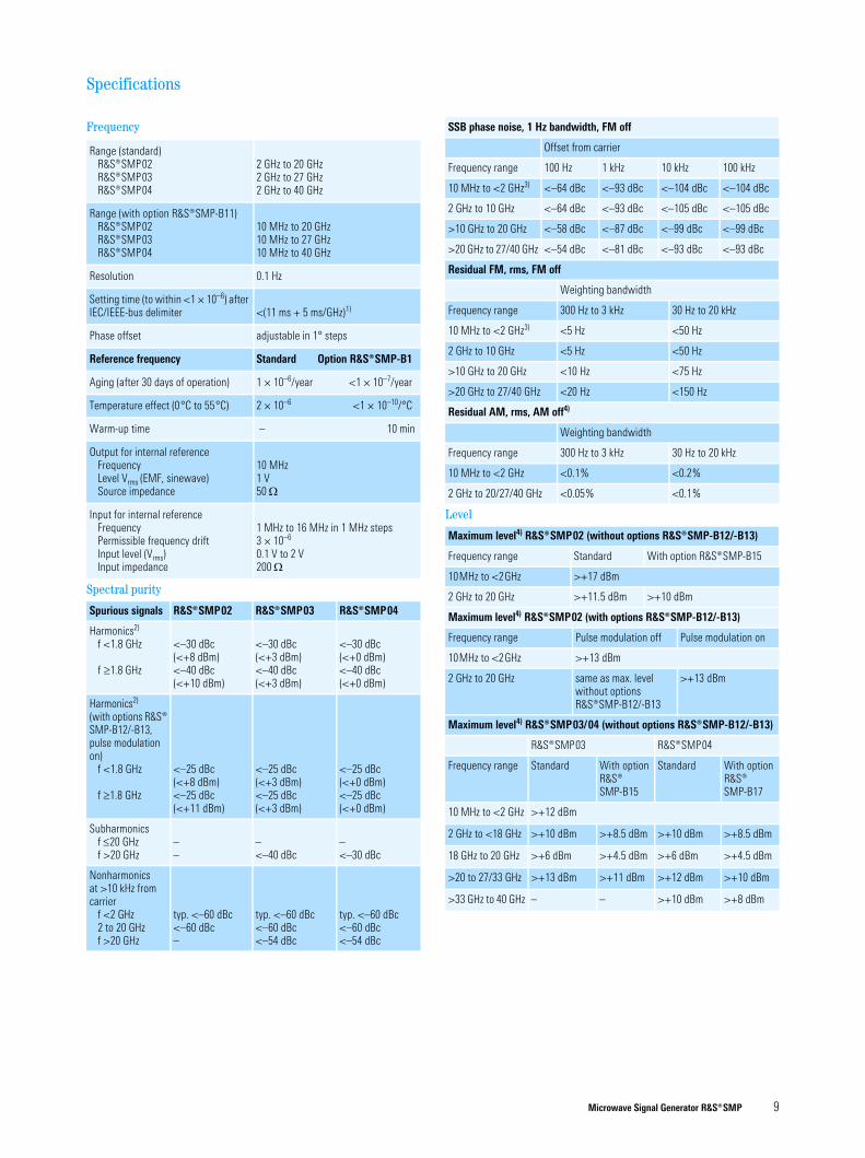
Specifications
Frequency
Range (standard)¸SMP02¸SMP03¸SMP04
2 GHz to 20 GHz2 GHz to 27 GHz2 GHz to 40 GHz
Range (with option ¸SMP-B11)¸SMP02¸SMP03¸SMP04
10 MHz to 20 GHz10 MHz to 27 GHz10 MHz to 40 GHz
Resolution 0.1 Hz
Setting time (to within <1 × 10⁻⁶) after IEC/IEEE-bus delimiter <(11 ms + 5 ms/GHz)1)
Phase offset adjustable in 1° steps
Reference frequency Standard Option ¸SMP-B1
Aging (after 30 days of operation) 1 × 10⁻⁶/year <1 × 10⁻⁷/year
Temperature effect (0°C to 55°C) 2 × 10⁻⁶ <1 × 10⁻¹⁰/°C
Warm-up time – 10 min
Output for internal referenceFrequencyLevel Vrms (EMF, sinewave)Source impedance
10 MHz1 V50 Ω
Input for internal referenceFrequencyPermissible frequency driftInput level (Vrms)Input impedance
1 MHz to 16 MHz in 1 MHz steps3 × 10–6
0.1 V to 2 V200 Ω
Spectral purity
Spurious signals ¸SMP02 ¸SMP03 ¸SMP04
Harmonics2)
f <1.8 GHz
f ≥1.8 GHz
<–30 dBc(<+8 dBm)<–40 dBc(<+10 dBm)
<–30 dBc(<+3 dBm)<–40 dBc(<+3 dBm)
<–30 dBc(<+0 dBm)<–40 dBc(<+0 dBm)
Harmonics2)
(with options ̧SMP-B12/-B13, pulse modulation on)
f <1.8 GHz
f ≥1.8 GHz
<–25 dBc(<+8 dBm)<–25 dBc(<+11 dBm)
<–25 dBc(<+3 dBm)<–25 dBc(<+3 dBm)
<–25 dBc(<+0 dBm)<–25 dBc(<+0 dBm)
Subharmonicsf ≤20 GHzf >20 GHz
––
–<–40 dBc
–<–30 dBc
Nonharmonicsat >10 kHz from carrier
f <2 GHz2 to 20 GHzf >20 GHz
typ. <–60 dBc <–60 dBc–
typ. <–60 dBc <–60 dBc<–54 dBc
typ. <–60 dBc<–60 dBc<–54 dBc
SSB phase noise, 1 Hz bandwidth, FM off
Offset from carrier
Frequency range 100 Hz 1 kHz 10 kHz 100 kHz
10 MHz to <2 GHz3) <–64 dBc <–93 dBc <–104 dBc <–104 dBc
2 GHz to 10 GHz <–64 dBc <–93 dBc <–105 dBc <–105 dBc
>10 GHz to 20 GHz <–58 dBc <–87 dBc <–99 dBc <–99 dBc
>20 GHz to 27/40 GHz <–54 dBc <–81 dBc <–93 dBc <–93 dBc
Residual FM, rms, FM off
Weighting bandwidth
Frequency range 300 Hz to 3 kHz 30 Hz to 20 kHz
10 MHz to <2 GHz3) <5 Hz <50 Hz
2 GHz to 10 GHz <5 Hz <50 Hz
>10 GHz to 20 GHz <10 Hz <75 Hz
>20 GHz to 27/40 GHz <20 Hz <150 Hz
Residual AM, rms, AM off4)
Weighting bandwidth
Frequency range 300 Hz to 3 kHz 30 Hz to 20 kHz
10 MHz to <2 GHz <0.1% <0.2%
2 GHz to 20/27/40 GHz <0.05% <0.1%
Level
Maximum level4) ¸SMP02 (without options ¸SMP-B12/-B13)
Frequency range Standard With option ¸SMP-B15
10MHz to <2GHz >+17 dBm
2 GHz to 20 GHz >+11.5 dBm >+10 dBm
Maximum level4) ¸SMP02 (with options ¸SMP-B12/-B13)
Frequency range Pulse modulation off Pulse modulation on
10MHz to <2GHz >+13 dBm
2 GHz to 20 GHz same as max. level without options ¸SMP-B12/-B13
>+13 dBm
Maximum level4) ¸SMP03/04 (without options ¸SMP-B12/-B13)
¸SMP03 ¸SMP04
Frequency range Standard With option ¸SMP-B15
Standard With option ¸SMP-B17
10 MHz to <2 GHz >+12 dBm
2 GHz to <18 GHz >+10 dBm >+8.5 dBm >+10 dBm >+8.5 dBm
18 GHz to 20 GHz >+6 dBm >+4.5 dBm >+6 dBm >+4.5 dBm
>20 to 27/33 GHz >+13 dBm >+11 dBm >+12 dBm >+10 dBm
>33 GHz to 40 GHz – – >+10 dBm >+8 dBm

10 Microwave Signal Generator ¸SMP
Maximum level4) ¸SMP03/SMP04 (with options ¸SMP-B12/-B13)
¸SMP03 ¸SMP04
Frequency range Pulse modu-lation off
Pulse modu-lation on
Pulse modula-tion off
Pulse modu-lation on
10 MHz to <2 GHz >+10 dBm
2 to 20/27/40 GHz same as max. level without options ¸SMP-B12/-B13
Minimum level of all modelsWithout option ¸SMP-B15/-B17With option ¸SMP-B15/-B17
–20 dBm–130 dBm
Resolution 0.1 dB or 0.01 dB
Total accuracy3)5) (frequency response and temperature effect included)
Frequency range Level Accuracy
10 MHz to <2 GHz >+10 dBm>–10 dBm>–60 dBm≤–60 dBm
<±1.2 dB<±0.6 dB<±0.9 dB<±1.4 dB
2 GHz to 20 GHz >+10 dBm>–10 dBm>–60 dBm≤–60 dBm
<±1.3 dB<±0.7 dB<±1.0 dB<±1.5 dB
>20 GHz to 27/40 GHz >+10 dBm>–10 dBm>–60 dBm≤–60 dBm
<±1.5 dB<±0.9 dB<±1.2 dB<±1.7 dB
Output impedance 1)2)3)4)5) 50 Ω
VSWRf ≤20 GHzf >20 GHz
<2, typ. <1.6<2.2, typ. <1.8
Setting time (after IEC/IEEE-bus delimiter)
With option ¸SMP-B15/-B17,with switching in attenuator set
<10 ms
<25 ms
Non-interrupting level setting (ATTENUATOR MODE FIXED)Setting range 0 dB to 20 dB
Simultaneous modulation any combination of AM (scan modula-tion), FM (ϕM) and pulse modulation
Linear amplitude modulation
Operating modes internal, external AC/DC
Modulation depth6) 0% to 90%
Resolution 0.1%
Setting accuracy at AF = 1 kHz(m <80%)7) <(4% of reading ±1%)
AM distortion at AF = 1 kHz (m = 60%)7), f >50 MHz <2%, typ. <1%
Modulation frequency range For frequency response <1 dB, m = 60%f <2 GHzf ≥2 GHz
DC to 100 kHz
DC to 10 kHzDC to 50 kHz
Modulation input EXT1Input impedanceInput voltage (peak value) for selected modulation depth
600 Ω or 100 kΩ
1 V (HIGH/LOW warning if variation >3%)
Logarithmic amplitude modulation (scan modulation)
Operating modes internal, external
Dynamic range >30 dB
Sensitivity 0.1 dB/V to 10 dB/V
Resolution 0.01 dB/V
Rise/fall time (10%/90%) <10 μs
Modulation input EXT1Input impedanceInput voltage
600 Ω or 100 kΩ–6 V to +6 V
Frequency modulation
Operating modes internal, external AC/DC, locked/unlocked, two-tone with two separate channels FM1 and FM2
Standard FM (without option ¸SM-B5)
Maximum deviationf ≤20 GHzf >20 GHz
Resolutionf ≤20 GHzf >20 GHz
Setting accuracy at AF = 100 kHz and 500 kHz deviationFM distortion at AF = 50 kHz and 500 kHz deviationModulation frequency rangeLocked modeUnlocked mode
Modulation frequency responseLocked mode, modulation index<10, deviation = 100 kHz10 kHz to 5 MHz
Unlocked mode, deviation = 10 MHz10 Hz (DC) to 100 kHz100 kHz to 5 MHz
Incidental AF = 50 kHz and 100 kHz deviationCarrier frequency offset with FMLocked modeUnlocked modef ≤20 GHzf >20 GHz
10 MHz20 MHz
<1%, min. 10 Hz<1%, min. 20 Hz
<10% of reading
<0.5%, typ. 0.05%
10 kHz to 5 MHzDC to 5 MHz
<5 dB
<1 dB<5 dB
<0.5%
–
typ. <10 MHztyp. <20 MHz
FM (with option ¸SM-B58))Maximum deviationf ≤20 GHzf >20 GHz
Resolutionf ≤20 GHzf >20 GHz
Setting accuracy at AF = 1 kHz and deviation >1 kHzFM distortion at AF = 1 kHz and500 kHz deviationModulation frequency rangeModulation frequency response10 Hz (DC) to 50 kHz50 kHz to 1 MHz
Incidental AF = 1 kHz and 40 kHz deviationCarrier frequency offset with FMf ≤20 GHzf >20 GHz
Carrier frequency drift with FM DCModulation inputs EXT1, EXT2Input impedanceInput voltage (peak value) for selected deviation
1 MHz2 MHz
<1%, min. 10 Hz<1%, min. 20 Hz
<2% of reading
<0.5%, typ. 0.05% DC to 1 MHz
<0.5 dB<4 dB
<0.5%
<100 Hz + 1% of deviation<200 Hz + 1% of deviationtyp. 0.005% of deviation per 1°C
600 Ω or 100 kΩ
1 V (HIGH/LOW warning if variation >3%)

Microwave Signal Generator ¸SMP 11
Phase modulation with option R&S®SM-B5
Operating modes internal, external AC/DC, two-tone with two separate channels ϕM1 and ϕM2
Maximum deviationf ≤20 GHzf >20 GHz
10 rad20 rad
Resolutionf ≤20 GHzf >20 GHz
<1%, min. 0.001 rad<1%, min. 0.002 rad
Setting accuracy at AF = 1 kHzf ≤20 GHzf >20 GHz
<(3% of reading + 0.01 rad)<(3% of reading + 0.02 rad)
ϕM distortion at AF = 1 kHz and 5 rad deviation <1%
Modulation frequency range DC to 100 kHz
Modulation frequency response 10 Hz (DC) to 100 kHz <3 dB
Modulation inputs EXT1, EXT2Input impedanceInput voltage (peak value)for selected deviation
600 Ω or 100 kΩ
1 V (HIGH/LOW warning if variation >3%)
ASK modulation
Operating mode external
Maximum modulation depth6) 90%
Resolution 0.1%
Data rate7) 0 Hz to 200 kHz
Rise/fall time (10%/90%) <10 μs
Modulation input EXT1Input impedanceInput level
600 Ω or 100 kΩTTL/HCT signal, selectable polarity
FSK modulation
Operating mode external
Maximum shiftStandard FMf ≤20 GHzf >20 GHz
With option ¸SM-B5f ≤20 GHzf >20 GHz
10 MHz20 MHz
1 MHz2 MHz
Resolutionf ≤20 GHzf >20 GHz
<1%, min. 10 Hz<1%, min. 20 Hz
Data rateStandard FMLocked modeUnlocked mode
With option ¸SM-B5
20 kHz to 2 MHz0 Hz to 2 MHz0 Hz to 2 MHz
Modulation input EXT1Input impedanceInput level
600 Ω or 100 kΩTTL/HCT signal, selectable polarity
Pulse modulation
Operating modes external, internal with option ¸SMP-B14
Standard (without options ¸SMP-B12/-B13)
Frequency rangeOn/off ratioRise/fall time (10%/90%)Minimum pulse widthMaximum pulse pauseWith level control switched on(ALC ON)
With level control switched off(ALC OFF)
Minimum pulse/pause ratioWith level control switched on(ALC ON)
With level control switched off(ALC OFF)
Pulse repetition frequencyPulse delayVideo feedthrough
≥2 GHz>50 dB (level >0 dBm)<1.5 μs 1 μs
any (¸SMP02/40 ms (¸SMP03/04)
any
any (¸SMP02/1:100 (¸SMP03/04)
any0 Hz to 500 kHztyp. 100 ns<15 mV (peak value)
With options ¸SMP-B12/-B13Frequency rangeWith option ¸SMP-B13With option ¸SMP-B12
On/off ratioRise/fall time (10%/90%)Minimum pulse widthWith level control switched on(ALC ON)
With level control switched off(ALC OFF)
Maximum pulse pauseWith level control switched on(ALC ON)
With level control switched off(ALC OFF)
Minimum pulse/pause ratioWith level control switched on(ALC ON)
with level control switched off(ALC OFF)
Pulse repetition frequencyPulse delayVideo feedthroughPULSE modulation inputInput levelInput impedance
10 MHz to <2 GHz≥2 GHz>80 dB<10 ns
20 ns (¸SMP02/1 μs (SMP03/04)
20 ns
any (¸SMP02/40 ms (¸SMP03/04)
any
any (¸SMP02/1:100 (¸SMP03/04)
any0 Hz to 10 MHztyp. 50 ns<15 mV (peak value)
TTL (HCT)50 Ω or 10 kΩ
Internal modulation generator
Frequency 0.4/1/3/15 kHz ± 3%
Open-circuit voltage at LF connector 1 V ± 1% (Rout = 10 Ω, Rload >200 Ω) (peak value)

Microwave Signal Generator ¸SMP 12
LF generator option R&S®SM-B2
Waveforms sinewave, triangular, squarewave, noise
Frequency rangeSinewave, noiseTriangular, squarewave
0.1 Hz to 500 kHz0.1 Hz to 50 kHz
Resolution 0.1 Hz
Frequency accuracy <1 × 10⁻⁴
Frequency response (sinewave)Up to 100 kHzUp to 500 kHz
<0.3 dB<0.5 dB
Distortion (20 Hz to 100 kHz) <0.1% (for level >0.5 V)
Open-circuit voltage at LF connectorResolutionSetting accuracy at 1 kHz
1 mV to 4 V (Rout = 10 Ω, Rload >200 Ω)1 mV±1% + 1 mV
Frequency setting time (after IEC/IEEE-bus delimiter) <10 ms
Pulse generator option R&S®SMP-B14
Operating modes single pulse, delayed pulse, double pulse
Active trigger edge positive or negative
Pulse repetition periodResolutionAccuracy
100 ns to 85 s5 digits, min. 20 nssame as reference frequency
Pulse widthResolutionAccuracy
40 ns to 1 s4 digits, min. 20 ns<(5% of reading ± 3 ns)
Pulse delayResolutionAccuracy
40 ns to 1 s4 digits, min. 20 ns±5% of reading–10 ns to +20 ns
Double pulseResolutionAccuracy
60 ns to 1 s4 digits, min. 20 ns±5% of reading–10 ns to +20 ns
Trigger delay <50 ns
PULSE modulation inputInput levelInput impedance
TTL (HCT)50 Ω or 10 kΩ
SYNC output TTL level (HC), 40 ns pulse width
VIDEO output TTL level (HC)
PPPD PW
SYNC output
VIDEO output
RF output
The pulse generator option enables the pulse delay PD, pulse width PW and
pulse repetition period PP to be set with high accuracy and resolution.
RF control output
Frequency range 2 GHz to 20 GHz
Level approx. 0 dBm
Sweep
digital sweep in discrete steps
RF sweep, AF sweepOperating modes
Sweep rangeLinear step width Logarithmic step width
AF sweep with option ¸SM-B2automatic, single-shot, manual or ex-ternally triggered, linear or logarithmic
user-selectable0.01% to 50%
Level sweepOperating modes
Sweep rangeStep width
automatic, single-shot, manual or externally triggered, logarithmic0.1 dB to 20 dB0.1 dB to 20 dB
Step timeResolution
10 ms to 1 s0.1 ms
Markers 3, user-selectable
MARKER output TTL/HC logic signal, selectable polarity
X output 0 V to 10 V
BLANK output TTL/HC logic signal, selectable polarity
TRIGGER input TTL/HCT logic signal, polarity of active trigger edge selectable
STOP input TTL/HCT logic signal, selectable polarity
LIST mode
frequency and level values can be stored and read out fast; permissible level variation range: 20 dB
Operating modes automatic, single-shot, manual or externally triggered
Max. length of list 2003 pairs of frequency and level values
Step time
Resolution
(1 ms to 1 s) + the lesser of 5 ms/GHz or 50 ms0.1 ms
Memory for instrument settings
Storable settings 50
Memory sequence modesOperating modes automatic, single-shot, manual or
externally triggered
Step timeResolution
50 ms to 60 s1 ms

Microwave Signal Generator ¸SMP 13
Auxiliary interface with option R&S®SMP-B18
V/GHz output output voltage proportional to frequen-cy, 0.5 V/GHz9) or 1 V/GHz selectable
Z output user-selectable level range –10 V to +10 V
Remote control
System IEC625 (IEEE488)
Command set SCPI 1992.0
Connector 24-contact Amphenol
IEC/IEEE-bus address 0 to 30
Interface functions SH1, AH1, T6, L4, SR1, RL1, PP1, DC1, DT1, C0
General data
Power supply 90 V to 132 V (AC), 47 Hz to 440 Hz180 V to 265 V (AC), 47 Hz to 440 Hzautoranging, max. 400 VAsafety class I to VDE 0411 (IEC348)
Electromagnetic compatibility
Standards adhered to postal regulation 243/1991EN55011 (VDE 0875 T11), class BVDE 0875, suppression level KMIL-STD-461B– RE02 radiated emissions– CE03 conducted emissions– CS01/02 conducted susceptibility
RF leakage (f <1 GHz) <0.1 μV (induced in a two-turn coil 2.5 cm in diameter held 2.5 cm away from the surface of the case)
Radiated susceptibility 3 V/m
Ambient conditions
Operating temperature range 0°C to 55°C10)
Storage temperature range –40°C to +70°C
Humidity IEC68-2-30, +40°C
Mechanical stress
Shock to MIL-STD-810D, 40 g shock spectrum
VibrationSinusoidalRandom
to IEC68-2-6, 5 Hz to 55 Hz10 m/s2 rms, 10 Hz to 300 Hz
Dimensions (W × H × D) 435 mm × 192 mm × 570 mm
Weight 27 kg, when fully equipped
1) For frequency changes beyond the 2 GHz and 20 GHz frequency limit the setting time is max. 50 ms longer.
2) Specifications for harmonics above 20 GHz (¸SMP02), 27 GHz (¸SMP03) and 40 GHz (¸SMP04) only typical.
3) Without optional Attenuator ̧ SMP-B15/-B17 specifications apply to levels >–5 dBm only.4) The maximum level is reduced by up to 2 dB in the temperature range 35°C to 55°C.5) The specified accuracy only applies to temperatures from 15°C to 35°C. Outside this range the
accuracy may be degraded by max. 0.7 dB.6) The modulation depth adjustable within the AM specifications continuously decreases from
6 dB below the maximum level up to the maximum level.7) This specification does not apply to
a) non-interrupting level setting (ATTENUATOR MODE FIXED) if option ̧ SMP-B15/-B17 is used,
b) levels below –5 dBm without option ̧ SMP-B15/-B17,c) external level control mode (EXT ALC).
8) The functions of the standard FM remain available.9) Above 20 GHz (¸SMP03/04) only 0.5 V/GHz available.10) The contrast of the LC display is degraded at high temperatures.

www.rohde-schwarz.comEurope: +49 1805 12 4242, [email protected]
USA and Canada: +1-888-837-8772, [email protected]
Asia: +65 65 130 488, [email protected]
¸ is
a re
gist
ered
trad
emar
k of
Roh
de&
Schw
arz G
mbH
&Co
. KG
· Tra
de n
ames
are
trad
emar
ks o
f the
ow
ners
· Pr
inte
d in
Ger
man
y (U
sk)
PD 0
758.
0951
.32
· ¸SM
P · V
ersi
on 0
5.01
· Oc
tobe
r 200
5/M
ay 2
007·
Dat
a w
ithou
t tol
eran
ce li
mits
is n
ot b
indi
ng ·
Subj
ect t
o ch
ange
Ordering information
Designation Type Order No.
Microwave Signal Generator ¸SMP02 1035.5005.02
Microwave Signal Generator ¸SMP03 1035.5005.03
Microwave Signal Generator ¸SMP04 1035.5005.04
Accessories supplied power cable, operating manual
For ¸SMP02/03For ¸SMP04
female adapter 3.5 mm female adapter 2.9 mm
Options
OCXO Reference Oscillator ¸SMP-B1 1036.5109.02
Frequency Extension 0.01 GHz to 2 GHz1) ¸SMP-B11 1036.6240.02
Pulse Modulator2 GHz to 20 GHz(¸SMP02)1)
2 GHz to 27 GHz(¸SMP03)1)
2 GHz to 40 GHz(¸SMP04)1)
0.01 GHz to 2 GHz1)
¸SMP-B12
¸SMP-B12
¸SMP-B12¸SMP-B13
1036.5750.02
1036.5750.03
1036.5750.041036.7147.02
Pulse Generator ¸SMP-B14 1036.7347.02
RF Attenuator27 GHz (¸SMP02, ¸SMP03)1)
40 GHz (¸SMP04)1)¸SMP-B15¸SMP-B17
1036.5250.021036.5550.02
Auxiliary Interface ¸SMP-B18 1036.8920.02
Rear Connectors for RF, AF¸SMP02, ¸SMP031)
¸SMP041)¸SMP-B19¸SMP-B20
1039.4303.021039.4503.02
LF Generator ¸SM-B2 1036.7947.02
FM/ϕM Modulator ¸SM-B5 1036.8489.02
19" Rack Adapter ¸ZZA-94 0396.4905.00
Extras
Service Kit ¸SM-Z3 1085.2500.02
Trolley ¸ZZK-1 1014.0510.00
Transit Case ¸ZZK-945 1013.9372.00
Adapter (¸SMP02, ¸SMP03)
3.5 mm, female3.5 mm, maleN, femaleN, male
1021.0512.001021.0529.001021.0535.001021.0541.00
Adapter (¸SMP04)2.9 mm, female2.9 mm, maleN, femaleN, male
1036.4790.001036.4802.001036.4777.001036.4783.00
1) Factory-fitted option.
Designation Type Order No.
Certified Quality System
ISO 9001DQS REG. NO 1954 QM
Certified Environmental System
ISO 14001DQS REG. NO 1954 UM
More information at www.rohde-schwarz.com
(search term: SMP)


